Huawei Technologies CBTS3612-1900 CDMA Base Station User Manual
Huawei Technologies Co.,Ltd CDMA Base Station
Contents
User Manual
HUAWEI
Airbridge cBTS3612 CDMA Base Station
User Manual
System Description
HUAWEI
Airbridge cBTS3612 CDMA Base Station
User Manual
Local Maintenance Terminal
HUAWEI
Airbridge cBTS3612 CDMA Base Station
User Manual
BTS Maintenance

1.5cm
7cm Font: Arial 22pt ,
Product name: Bold
5.3cm
0.7cm
Airbridge cBTS3612 CDMA Base Station
User Manual
5cm
HUAWEI
4cm
Ver: T2-030160-
20030125-C-1.21
BOM: 31013260
2.5cm, Font: Arial, 9
pt

Huawei Technologies Co., Ltd.
Administration Building, Huawei Technologies
Co., Ltd., Bantian, Longgang District,
Shenzhen, P. R. China
Postal Code: 518129
Website: http://www.huawei.com
BOM: 31013260

Airbridge cBTS3612 CDMA Base Station User Manual
Airbridge cBTS3612 CDMA Base Station User Manual
Airbridge cBTS3612 CDMA Base Station User Manual
Airbridge cBTS3612 CDMA Base Station User Manual
15.7cm
Huawei Technologies Co., Ltd.
Huawei Technologies Co., Ltd.
Huawei Technologies Co., Ltd.
Huawei Technologies Co., Ltd.
10cm
1. 16K Cover for hectograph; Font: Arial 22 pt; Product name: Bold
Airbridge cBTS3612
CDMA Base Station
User Manual
HUAWEI
1. System Description
2. Local Maintenance Terminal
3. BTS Maintenance
Airbridge cBTS3612 CDMA Base Station
User Manual
V100R002

Airbridge cBTS3612 CDMA Base Station
User Manual
Manual Version T2-030160-20030125-C-1.21
Product Version V100R002
BOM 31013260
Huawei Technologies Co., Ltd. provides customers with comprehensive technical support
and service. Please feel free to contact our local office, customer care center or company
headquarters.
Huawei Technologies Co., Ltd.
Address: Administration Building, Huawei Technologies Co., Ltd.,
Bantian, Longgang District, Shenzhen, P. R. China
Postal Code: 518129
Website: http://www.huawei.com
Email: support@huawei.com

© 2003 Huawei Technologies Co., Ltd.
All Rights Reserved
No part of this document may be reproduced or transmitted in any form or by any
means without prior written consent of Huawei Technologies Co., Ltd.
Trademarks
, HUAWEI, C&C08, EAST8000, HONET, , ViewPoint, INtess, ETS, DMC,
TELLIN, InfoLink, Netkey, Quidway, SYNLOCK, Radium, M900/M1800,
TELESIGHT, Quidview, Musa, Airbridge, Tellwin, Inmedia, VRP, DOPRA, iTELLIN,
HUAWEI OptiX, C&C08 iNET, NETENGINE, OptiX, SoftX, iSite, U-SYS, iMUSE,
OpenEye, Lansway, SmartAX are trademarks of Huawei Technologies Co., Ltd.
Notice
The information in this document is subject to change without notice. Every effort
has been made in the preparation of this document to ensure accuracy of the
contents, but all statements, information, and recommendations in this document
don't constitute the warranty of any kind, express or implied.
About This Manual
Version
The product version corresponds to the manual is Airbridge cBTS3612 CDMA Base
Station V100R002.
Contents
This User Manual gives a systematic introduction on the technical principles, structures
and maintenance methods of Airbridge cBTS3612 CDMA Base Station (cBTS3612
hereafter).
It is divided into three modules:
z Module 1 System Description
This module introduces the technical principles, software and hardware structures,
functions, networking configurations and performance indices of cBTS3612.
z Module 2 Local Maintenance Terminal
This module introduces how to use the cBTS3612 local maintenance terminal. First is
the guide to the local maintenance terminal, second is the detailed introduction of the
local commands, including configuration commands and maintenance commands.
z Module 3 BTS Maintenance
This module introduces how to maintain the cBTS3612 BTS, including routine
maintenance instructions, fault analysis and location, component replacement and
component description.
Target Readers
The manual is intended for the following readers:
z Installation engineers & technicians
z Operation & maintenance personnel

Conventions
This document uses the following conventions:
I. General conventions
Convention Description
Arial Normal paragraphs are in Arial.
Arial Narrow Warnings, cautions, notes and tips are in Arial Narrow.
Terminal Display
Terminal Display is in Courier New; message input by the user
via the terminal is in boldface.
II. Command conventions
Convention Description
boldface font Command keywords (which must be input unchanged) are in boldface.
italic font Command arguments for which you supply values are in italics.
[ ] Elements in square brackets [ ] are optional.
{ x | y | ... }
Alternative keywords are grouped in braces and separated by vertical bars. One is
selected.
[ x | y | ... ]
Optional alternative keywords are grouped in square brackets and separated by
vertical bars. One (or none) is selected.
{ x | y | ... } *
Alternative keywords are grouped in braces and separated by vertical bars. A
minimum of one and maximum of all can be selected.
[ x | y | ... ] *
Optional alternative keywords are grouped in square brackets and separated by
vertical bars. Many (or none) are selected.
! A line starting with an exclamation mark is comments.
III. GUI conventions
Convention Description
< > Message entered via the terminal is within angle brackets.
[ ] MMIs, menu items, data table and field names are inside square brackets [ ].
/ Multi-level menus are separated by forward slashes (/). Menu items are in
boldface. For example, [File/Create/Folder].

IV. Keyboard operation
Format Description
<Key> Press the key with key name expressed with a pointed bracket, e.g.
<Enter>, <Tab>, <Backspace>, or<A>.
<Key1+Key2> Press the keys concurrently; e.g. <Ctrl+Alt+A>means the three keys should
be pressed concurrently.
<Key1, Key2> Press the keys in turn, e.g. <Alt, A>means the two keys should be pressed
in turn.
[Menu Option] The item with a square bracket indicates the menu option, e.g. [System]
option on the main menu. The item with a pointed bracket indicates the
functional button option, e.g. <OK> button on some interface.
[Menu1/Menu2/Menu3] Multi-level menu options, e.g. [System/Option/Color setup] on the main
menu indicates [Color Setup] on the menu option of [Option], which is on
the menu option of [System].
V. Mouse operation
Action Description
Click Press the left button or right button quickly (left button by default).
Double Click Press the left button twice continuously and quickly.
Drag Press and hold the left button and drag it to a certain position.
VI. Symbols
Eye-catching symbols are also used in this document to highlight the points worthy of
special attention during the operation. They are defined as follows:
Caution, Warning, Danger: Means reader be extremely careful during the operation.
Note Comment, Tip, Knowhow, Thought: Means a complementary description.

User Manual
Airbridge cBTS3612 CDMA Base Station System Description
Table of Contents
i
Table of Contents
1 System Overview ..............................................................................................................1-1
1.1 Brief Introduction.......................................................................................................1-1
1.2 System Features .......................................................................................................1-3
1.2.1 Advanced Technology and Excellent Performance............................................1-3
1.2.2 Protecting User Investment..............................................................................1-4
1.2.3 Convenient Operation and Maintenance...........................................................1-4
1.2.4 Flexible Networking Mode................................................................................1-5
1.2.5 Reliable Power Supply System ........................................................................1-5
1.2.6 Multi-band supported .......................................................................................1-6
1.3 Technical Index .........................................................................................................1-6
1.4 External Interface......................................................................................................1-9
1.4.1 Overview.........................................................................................................1-9
1.4.2 Um Interface ................................................................................................. 1-10
1.4.3 Abis Interface................................................................................................ 1-14
1.4.4 OML Interface............................................................................................... 1-18
1.4.5 LMF Interface................................................................................................ 1-18
1.4.6 System Synchronization Interface.................................................................. 1-18
1.4.7 BTS Test Interface ........................................................................................ 1-18
1.4.8 Remote Maintenance Serial Port .................................................................... 1-19
1.4.9 Environment Alarm Interface..........................................................................1-19
1.5 Reliability Design .................................................................................................... 1-19
1.5.1 Hardware Reliability Design ........................................................................... 1-20
1.5.2 Software Reliability Measures ........................................................................ 1-23
2 Hardware Architecture ......................................................................................................2-1
2.1 Overview ..................................................................................................................2-1
2.2 Baseband Subsystem................................................................................................2-5
2.2.1 Overview.........................................................................................................2-5
2.2.2 Control & Clock Module (BCKM) ......................................................................2-7
2.2.3 Control Interface Module (BCIM).................................................................... 2-10
2.2.4 Channel Processing Module (BCPM) ............................................................. 2-12
2.2.5 Resource Distribution Module (BRDM) ...........................................................2-14
2.2.6 Baseband Backplane Module (CBKM)............................................................ 2-17
2.2.7 E1 Surge Protector (BESP)............................................................................2-19
2.2.8 Fan Module (BFAN)....................................................................................... 2-20
2.3 RF Subsystem ........................................................................................................ 2-24
2.3.1 Overview....................................................................................................... 2-24
2.3.2 BTS Transceiver Module (BTRM)................................................................... 2-25

User Manual
Airbridge cBTS3612 CDMA Base Station System Description
Table of Contents
ii
2.3.3 BTS High Power Amplifier Module (BHPA).....................................................2-28
2.3.4 BTS Transceiver Backplane Module (BTBM) .................................................. 2-30
2.3.5 Combining Duplexer Unit (CDU)..................................................................... 2-31
2.3.6 Duplexer Filter Unit (DFU) ............................................................................. 2-33
2.3.7 Dual Duplexer Unit (DDU).............................................................................. 2-35
2.3.8 Receive LNA Distribution Unit (RLDU)............................................................ 2-37
2.3.9 BTS RF Fan Module (BRFM).........................................................................2-39
2.4 Antenna & Feeder Subsystem ................................................................................. 2-43
2.4.1 Overview....................................................................................................... 2-43
2.4.2 RF Antenna & Feeder.................................................................................... 2-43
2.4.3 Dual-Satellite Synchronization Antenna & Feeder ........................................... 2-47
2.5 Power Supply Subsystem ........................................................................................ 2-50
2.5.1 Overview....................................................................................................... 2-50
2.5.2 General Structure.......................................................................................... 2-51
2.5.3 Technical Indices..........................................................................................2-51
2.5.4 Power Supply Monitoring ............................................................................... 2-54
2.5.5 BTS Direct Current Switchbox (BDCS) ........................................................... 2-55
2.6 Environment Monitoring........................................................................................... 2-55
2.6.1 Alarm Box Input ............................................................................................. 2-56
2.6.2 Alarm Indicator .............................................................................................. 2-56
2.6.3 Interface for Actuators ...................................................................................2-57
2.6.4 Communication ............................................................................................. 2-57
2.7 Lightning Protection System .................................................................................... 2-57
2.7.1 Overview....................................................................................................... 2-57
2.7.2 Lightning Protection for DC............................................................................ 2-59
2.7.3 Lightning Protection for Trunk Line ................................................................. 2-60
2.7.4 Lightning Protection for Antenna & Feeder Port .............................................. 2-62
3 Software Architecture .......................................................................................................3-1
3.1 Overall Architecture...................................................................................................3-1
3.2 Module Description ...................................................................................................3-2
3.2.1 Main Control Software .....................................................................................3-2
3.2.2 O&M Software.................................................................................................3-4
3.2.3 Clock Software................................................................................................3-6
3.2.4 BCIM Software................................................................................................3-7
3.2.5 BCPM Software...............................................................................................3-8
3.2.6 BRDM Software ..............................................................................................3-9
3.2.7 BTRM Software ............................................................................................. 3-10
4 System Function ...............................................................................................................4-1
4.1 Transmission Networking ..........................................................................................4-1
4.2 Call Procedure..........................................................................................................4-3
4.2.1 Speech Service Call Procedure........................................................................4-3
4.2.2 Data Service Call Procedure............................................................................4-6

User Manual
Airbridge cBTS3612 CDMA Base Station System Description
Table of Contents
iii
4.3 Signaling Processing .................................................................................................4-9
4.4 Baseband Processing.............................................................................................. 4-11
4.5 RF Functions ..........................................................................................................4-13
4.5.1 Power Control ............................................................................................... 4-13
4.5.2 Handoff ......................................................................................................... 4-15
4.5.3 Flexible Configuration .................................................................................... 4-15
4.5.4 Radio Configuration and Channel Support ...................................................... 4-16
4.5.5 Easy Installation and Operation...................................................................... 4-21
4.5.6 Diversity Receiving ........................................................................................ 4-21
4.5.7 Cell Breath.................................................................................................... 4-22
4.6 Operation and Maintenance.....................................................................................4-22
4.6.1 Software Loading ..........................................................................................4-22
4.6.2 Interface Management ................................................................................... 4-23
4.6.3 Test Management .........................................................................................4-24
4.6.4 Status Management ......................................................................................4-24
4.6.5 Event Reporting and Processing .................................................................... 4-25
4.6.6 Equipment Management ................................................................................ 4-26
4.6.7 Site Configuration.......................................................................................... 4-28
4.6.8 Operation Status Tracing............................................................................... 4-29
4.6.9 Other Functions............................................................................................. 4-29
5 System Configuration .......................................................................................................5-1
5.1 Overview ..................................................................................................................5-1
5.1.1 Basic/Extended Cabinet Configuration .............................................................5-1
5.1.2 Baseband Subrack Configuration.....................................................................5-4
5.1.3 Power Supply Subrack Configuration ...............................................................5-6
5.1.4 RF Modules Configuration ...............................................................................5-6
5.1.5 Configuration of Antenna Parts ........................................................................5-7
5.2 Typical Configurations ...............................................................................................5-8
5.2.1 Typical Configuration of cBTS3612 for 450MHz Band .......................................5-8
5.2.2 Typical Configuration of cBTS3612 for 800MHz Band ..................................... 5-14
5.2.3 Typical Configuration of cBTS3612 in 1900MHz Band..................................... 5-21
Appendix A Technical Performance of Receiver and Transmitter ..................................... A-1
A.1 Performance of Receiver...........................................................................................A-1
A.1.1 Frequency Coverage.......................................................................................A-1
A.1.2 Access Probe Acquisition ................................................................................A-1
A.1.3 R-TCH Demodulation Performance..................................................................A-1
A.1.4 Receiving Performance ...................................................................................A-9
A.1.5 Limitations on Emissions ...............................................................................A-10
A.1.6 Received Signal Quality Indicator (RSQI).......................................................A-11
A.2 Performance of Transmitter.....................................................................................A-11
A.2.1 Frequency Requirements ..............................................................................A-11
A.2.2 Modulation Requirements..............................................................................A-12

User Manual
Airbridge cBTS3612 CDMA Base Station System Description
Table of Contents
iv
A.2.3 RF Output Power Requirement ......................................................................A-12
A.2.4 Limitations on Emissions ...............................................................................A-13
Appendix B EMC Performance ........................................................................................... B-1
B.1 EMI Performance......................................................................................................B-1
B.2 EMS Performance ....................................................................................................B-2
Appendix C Environment Performance .............................................................................. C-1
C.1 Ambient Temperature and Humidity.......................................................................... C-1
C.2 Cleanness ............................................................................................................... C-1
C.3 Illumination .............................................................................................................. C-2
C.4 Atmospheric Condition ............................................................................................. C-2
Appendix D Electromagnetic Radiation.............................................................................. D-1
D.1 Introduction ............................................................................................................. D-1
D.2 Maximum Permissible Exposure (MPE) .................................................................... D-1
D.3 Estimation of Exposure to Electromagnetic Fields ..................................................... D-3
D.4 Calculation of Safe Distance .................................................................................... D-3
D.5 Location of Base Station Antennas ........................................................................... D-4
D.5.1 Exclusion Zones ............................................................................................ D-4
D.5.2 Guidelines on Arranging Antenna Locations .................................................... D-4
Appendix E Standard Compliance .......................................................................................E-1
E.1 Um Interface.............................................................................................................E-1
E.2 Abis Interface ...........................................................................................................E-1
E.3 Lightning Protection..................................................................................................E-2
E.4 Safety ......................................................................................................................E-3
E.5 EMC.........................................................................................................................E-3
Appendix F Abbreviation .....................................................................................................F-1
User Manual
Airbridge cBTS3612 CDMA Base Station System Description
1 System Overview
1-1
1 System Overview
This chapter firstly presents an outline of the cBTS3612 base station system, and
then briefs the system features, technical indices and external interfaces, followed
by an introduction to the system reliability design in aspects of hardware and
software.
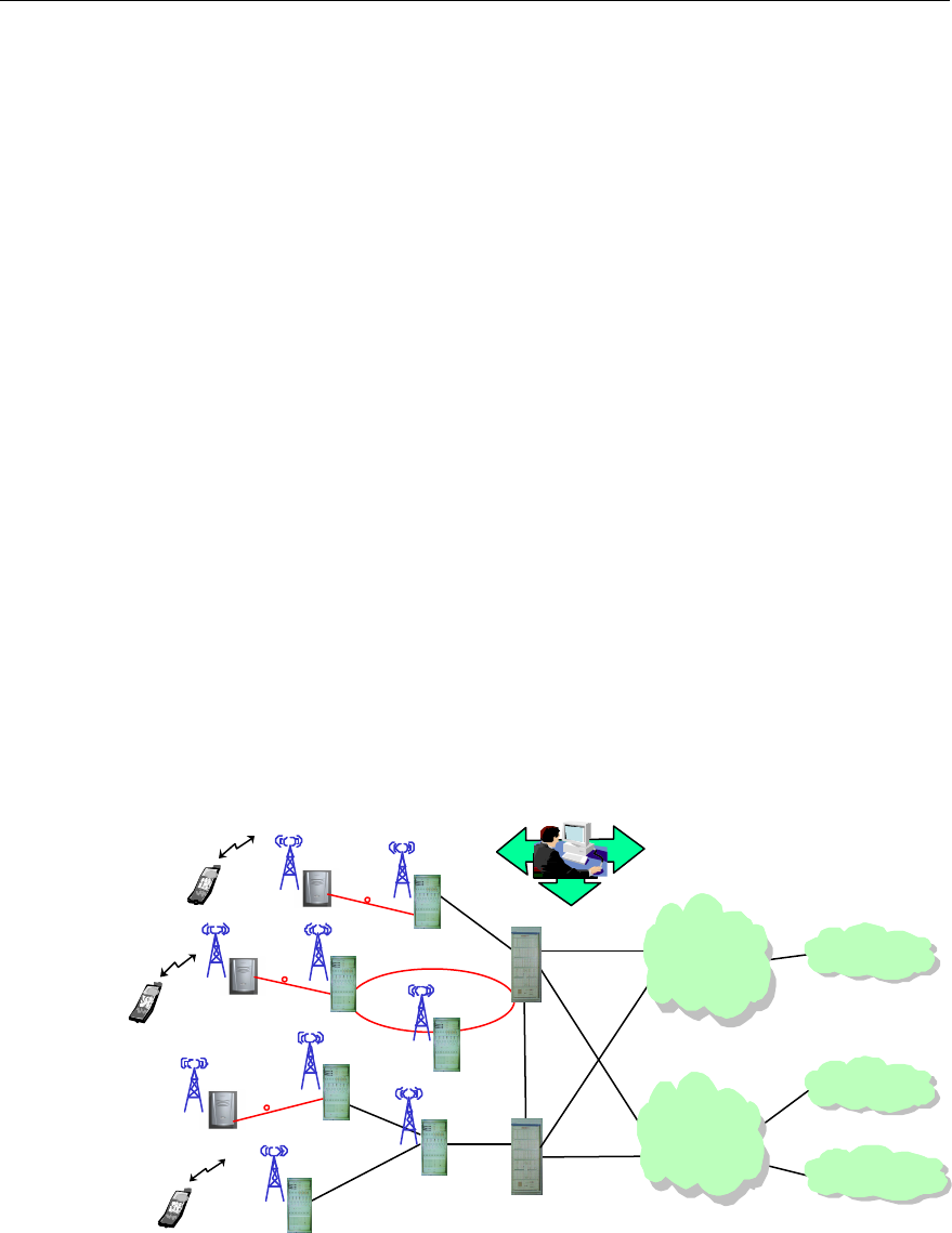
1.1 Brief Introduction
The cdma2000 1X mobile communication system comprises the Base Station
Subsystem (BSS) and the Core Network (CN). The BSS comprises the Base
Transceiver Station (BTS), Base Station Controller (BSC) and Packet Control
Function (PCF), while the CN comprises the packet domain network and circuit
domain network. The equipment of packet domain interworks with Internet, and that
of the circuit domain interworks with the conventional PLMN and PSTN/ISDN. The
system's operation and maintenance is implemented via the integrated mobile
network management system (iManager M2000).
The position of BTS in CDMA system is as shown in Figure 1-1.
Internet
PSTN/ISDN
PLMN
A3/A7
A1/A2
A10/A11
Abis
A1/A2
MS
Mobile Network
Management System
SoftSite
BSC/PCF
BSC/PCF
BTS
BTS
BTS
MS
MS
BTS
SoftSite
Packet Domain
Network Equipment
Circuit Domain
Network
Equipment
A10/A11
SoftSite
Abis
BTS
SDH
BTS
MS: Mobile Station BTS: Base Transceiver Station
BSC: Base Station Controller ISDN: Integrated Service Data Network
PLMN: Public Land Mobile Network PSTN: Public Switched Telephone Network
PCF: Packet Control Function Softsite: Soft Site
BSS: Base Station Subsystem CN: Core Network
Figure 1-1 Network structure of cdma2000 1X mobile communication system
User Manual
Airbridge cBTS3612 CDMA Base Station System Description
1 System Overview
1-2
cBTS3612 is located between the Base Station Controller (BSC) and the Mobile
Station (MS) in the cdma2000 1X mobile communication system.
Under the control of the BSC, the cBTS3612 serves as the wireless transceiving
equipment of one cell or multiple logical sectors. Connecting to BSC via the Abis
interface, it assists the BSC on the radio resource management, radio parameter
management and interface management. It also implements, via the Um interface,
the radio transmission between the BTS and the MS, as well as related control
functions.
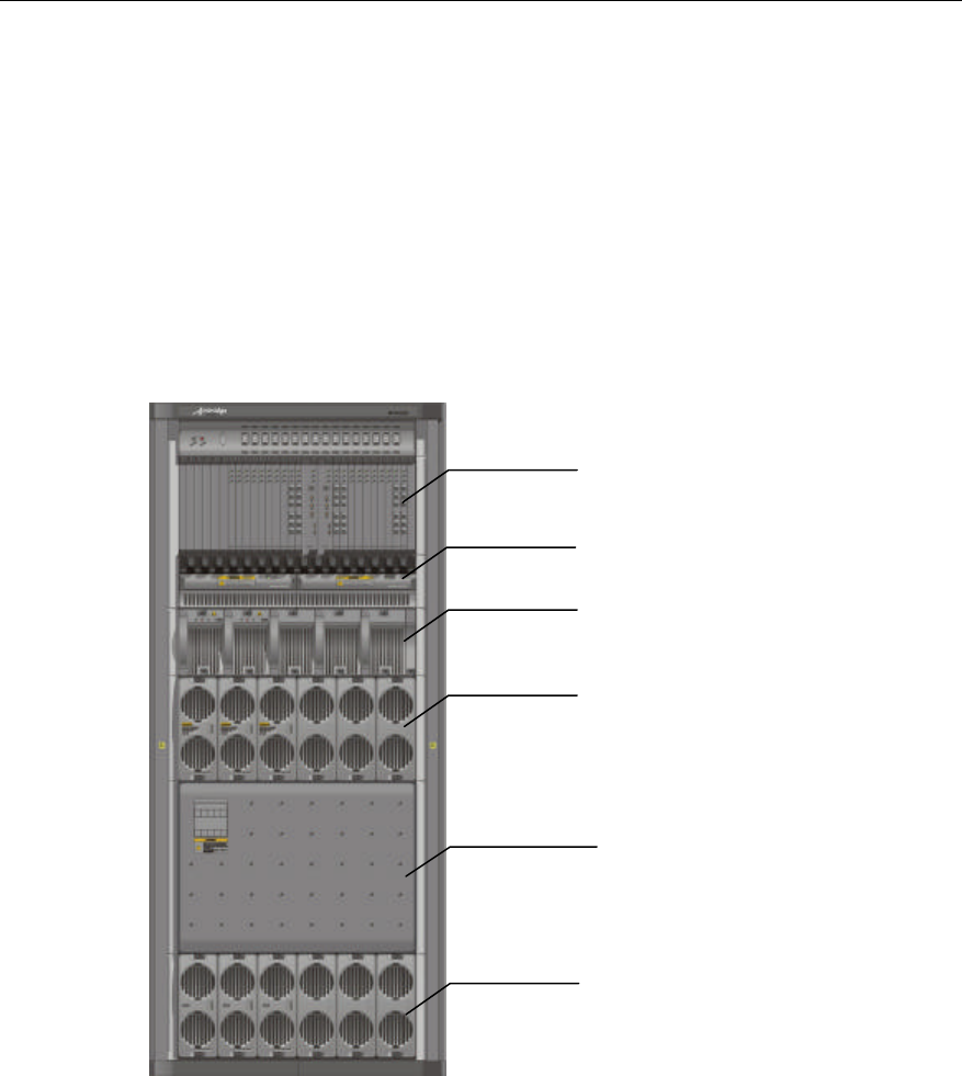
cBTS3612 cabinet is shown in Figure 1-2.
RF subrack
CDU/RLDU subrack
Fan subrack
Baseband subrack
RF subrack
Power subrack
Figure 1-2 cBTS3612 cabinet
cBTS3612 has the following functions:
I. Interface function
l Um interface supports IS2000 Release A. It is fully compatible with IS-95A/B.
l The physical layer supports a rate as high as 307.2kbit/s.
l Hard handoff, soft handoff and softer handoff are supported.
l Quick forward power control, slow forward power control, quick reverse power
control and reverse open-loop power control are available.

User Manual
Airbridge cBTS3612 CDMA Base Station System Description
1 System Overview
1-3
l Support omni-cell, directional 3 sectors and 6 sectors configurations.
l Abis interface supports E1/T1 trunk mode and optical fiber transmission mode
(optical fiber transmission mode will be available in the coming version). E1/T1
trunk mode supports as many as 16 E1/T1 trunk lines and optical fiber
transmission mode will support 2 pairs of STM-1 optical fibers.
l Chain, star and tree networking modes are supported.
l Softsite (ODU3601C) can be extended afar via optical fibers.
II. Basic functions of operation and maintenance
l Software downloading
l Abis interface management
l Air interface (Um) management
l Test management
l Status management
l Event report handling
l Equipment management
l Data configuration management
l BTS operation tracing
l Telnet logon
1.2 System Features
cBTS3612 features large capacity, high integration and low power consumption.
One cabinet can accommodate as many as 12 sector carriers. It can satisfy the
customer's demands on capacity, configuration, installation, power supply,
transmission and service. It's a typical "All In One" BTS. Its features are highlighted
as follows:
1.2.1 Advanced Technology and Excellent Performance
cBTS3612 integrates the following technologies to improve its performances:
l Based on well-developed Huawei ATM platform and cell switching & broadband
processing technology, standard interface and open application is enabled.
l Designed with the resource pool concept, which helps increase the availability
of hardware resources and the system's fault-tolerance.
l Equipped with the digital intermediate frequency technology to enhance
wireless signal transmitting and receiving capability.
l Designed with the technology of diversity receiving to improve the radio signal
receiving performance.
l Supporting remote installation of the SoftSite via optical fibers, thus making
networking more flexible.

User Manual
Airbridge cBTS3612 CDMA Base Station System Description
1 System Overview
1-4
l Equipped with the blind mate technology on the radio frequency module for
convenient maintenance.
l Intelligent fans with prolonged service life and reduced noise.
1.2.2 Protecting User Investment
The cBTS3612 is compatible with IS-95A/B and cdma2000 1X, and can be
upgraded to cdma2000 1X EV smoothly. When the network is upgraded from IS-95
to cdma2000 1X, or from cdma2000 1X to cdma2000 1X EV, the user's investment
can be saved.
The cBTS3612 features large-capacity design, modular structure and high
integration. A single cabinet can accommodate up to 12 sector carriers. It also
supports 36 sector carriers with three fully configured cabinets combined together.
Its baseband processing employs the resources pool design to reduce equipment
redundancy and improve reliability.
Its Abis interface supports 16 E1s or 2 STM-1 optical interfaces (in the coming
version), oriented to future high-speed data service.
Its excellent inheritance capability guarantees the original antenna and feeder
components can be used in the event of BTS expansion or upgrade. The
components include DU, RLDU, antenna, feeder and the optional TMA (The TMA
only applies to 19000MHz band). The DU includes CDU, DFU and DDU, the
difference between these 3 DUs will be introduced in "2.3 RF Subsystem".
1.2.3 Convenient Operation and Maintenance
Emergency serial ports are provided for the boards, so that the alarm information
can be reported in the case of communication link fault.
Real-time status query, online board test and system fault locating as well as system
restart functions are provided.
Telnet Server is provided so that the user can log in to the BTS via the local
Ethernet interface in the standard Telnet mode to perform O&M.
Modem dial-up is supported so that the remote O&M can be performed.
All boards of baseband subrack support hot plug/unplug for the sake of ready
maintenance, upgrade and expansion.
Blind mate of the radio frequency module guarantees that all operations can be
done at the front side of the equipment. During expansion and configuration, wiring
at the back need not be modified.

User Manual
Airbridge cBTS3612 CDMA Base Station System Description
1 System Overview
1-5
Its modularized structure reduces the internal connections and improves the
reliability of the system, and thus makes the installation and maintenance easier.
In the case of whole BTS interruption due to power supply or transmission causes,
the cBTS3612 system can restart automatically right after the faults are cleared.
1.2.4 Flexible Networking Mode
I. Networking for large capacity and wide coverage
l A single cabinet supports as many as 12 sector carriers. 3 cabinets can be
combined to provide a maximum capacity of 36 sector carriers.
l Large-capacity trunk. Abis interface of BTS supports as many as 16 E1s
transmission. The coming version will support STM-1 optical transmission in
ATM mode at Abis interface and provide two STM -1 ports for Abis interface
trunk.
l Support multiple BTS configurations such as omni 4 carriers, 1%3, 2%3, 12%3,
6%6(carrier%sector) configurations.
II. Supporting multiple BTS networking modes such as chain, star and tree
Refer to "4.1 Transmission Networking" for details.
III. Soft BTS networking (the SoftSite will be available in the coming version)
In this networking mode, the baseband unit adopts the centralized processing mode.
The baseband signals and maintenance information are transferred through the fiber
to the SoftSite (ODU3601C). The SoftSite can be applied indoors, outdoors or
underground.
The SoftSite, small in size, is equipped with built-in power supply, temperature
regulator and monitoring device. It can be used in severe environments, e.g.
outdoors. The feeder loss of the SoftSite is trivial, making large coverage for macro
cells possible.
SoftSites in the chain-networking mode are applicable to highways and subways. A
maximum of 6 SoftSites can be connected in serial in one pair of optical fibers.
1.2.5 Reliable Power Supply System
The DC/DC power supply with -48V DC power input, and +27V DC output is
adopted. The whole power supply system is composed of 5 modules in full
configuration, with automatic current equalization function, 4+1 redundancy, meeting
the requirement of 8000W power supply.

User Manual
Airbridge cBTS3612 CDMA Base Station System Description
1 System Overview
1-6
Current equalization hot backup, centralized management, and decentralized power
supply are enabled. It makes the power supply system safer and more reliable. It
provides automatic alarming through monitoring interface for the power fan, input
under-voltage, output over-voltage, overheat and protection against reverse
connection. This ensures the reliability of the power system. Remote power on/off
function enables unattended BTS operation and remote maintenance.
1.2.6 Multi-band supported
Now the cBTS3612 base station support the following band class specified in
TIA/EIA-97-D Recommended Minimum Performance Standards for cdma2000
Spread Spectrum Base Stations.
Band Class 0 (800 MHz Band).
Band Class 1 (1900 MHz Band).
Band Class 5 (450 MHz Band).
To support the different band classes, RF modules with different specifications
should be configured in cBTS3612 base station.
1.3 Technical Index
I. Structure and environment indices
Cabinet dimensions (Top set excluded) 1800mm x 800mm x 650mm (H x W x D)
Power supply -48V DC (-40 - -60V DC)
Operational environment Temperature: -5°C ~ 50°C
Relative humidity: 5% ~ 90%
Equipment room noise 70dBA (With intelligent fan control. The noise varies with the
ambient temperature)
&
Note:
In terms of environment adaptability, cBTS3612 conforms to the following specifications: IEC 60721-3
series, IEC 60068-2 and ETS 300 019-2 series. For details, please refer to Appendix C Environment
Performance.
Equipment room noise is In compliance with ETS 300 753 Noise Requirement for telecommunication
equipment and base station environment. When the inside temperature of cBTS3612 equipment room
is 50âC, the equipment noise is less than 70dBA, and when the temperature is 25âC, the equipment
noise is less than 60dBA.

User Manual
Airbridge cBTS3612 CDMA Base Station System Description
1 System Overview
1-7
II. Clock indices
Frequency stability <±5 x 10⁻⁸
Annual aging rate <±5 x 10⁻¹⁰
III. System capacity
Full configuration of one cabinet 12 sector-carriers
Full configuration of three cabinets 36 sector-carriers
IV. Power consumption and cabinet weight
Site configuration Power consumption (W) Cabinet weight (kg)
S(1/1/1) <1500 351
S(2/2/2) <2800 388
S(4/4/4) <5500 550
V. Transmitter indices
l 450MHz Band
Working band 460 - 470MHz
Channel bandwidth 1.23MHz
Channel precision 25kHz
Frequency tolerance ±0.05ppm
Transmitting power 20W (The maximum value measured at the cabinet-top
feeder port)
l 800MHz Band
Working band 869 - 894MHz
Channel bandwidth 1.23MHz
Channel precision 30kHz
Frequency tolerance ±0.05ppm
Transmitting power 20W (The maximum value measured at the cabinet-top
feeder port)
l 1900MHz Band

User Manual
Airbridge cBTS3612 CDMA Base Station System Description
1 System Overview
1-8
Working band 1930 - 1990MHz
Channel bandwidth 1.23MHz
Channel precision 50kHz
Frequency tolerance ±0.05ppm
Transmitting power 20W (The maximum value measured at the cabinet-top
feeder port)
VI. Receiver indices
l 450MHz Band
Working band 450 - 460MHz
Channel bandwidth 1.23MHz
Channel precision 25kHz
Sensitivity of signal receiver Better than -126dB (RC3, main and diversity receiving)
l 800MHz Band
Working band 824 - 849MHz
Channel bandwidth 1.23MHz
Channel precision 30kHz
Sensitivity of signal receiver Better than –127dBm (RC3, main and diversity receiving)
l 1900MHz Band
Working band 1850 - 1910MHz
Channel bandwidth 1.23MHz
Channel precision 50kHz
Sensitivity of signal receiver Better than –126dBm (RC3, main and diversity receiving)
VII. Rate configuration on Um interface
Rate configuration Forward Reverse
Mode 1 RC1 RC1
Mode 2 RC2 RC2
Mode 3 RC3 or RC4 RC3
Mode 4 RC5 RC4

User Manual
Airbridge cBTS3612 CDMA Base Station System Description
1 System Overview
1-9
VIII. EMC indices
ETSI EN 300 386 Electromagnetic compatibility and Radio spectrum Matters (ERM)
- Telecommunication network equipment - ElectroMagnetic Compatibility (EMC)
requirements is the universal EMC standard of telecommunication equipment. The
EMC indices of the cBTS3612 comply with ETSI EN 300 386 V1.2.1 (2000 – 03).
IX. System reliability
MTBF (hour) 100000
MTTR (hour) 1
Availability (A) 99.999%
&
Note:
The performance of cBTS3612 base station satisfies or excels TIA/EIA-97-D: Recommended Minimum
Performance Standards for cdma2000 Spread Spectrum Base Stations.
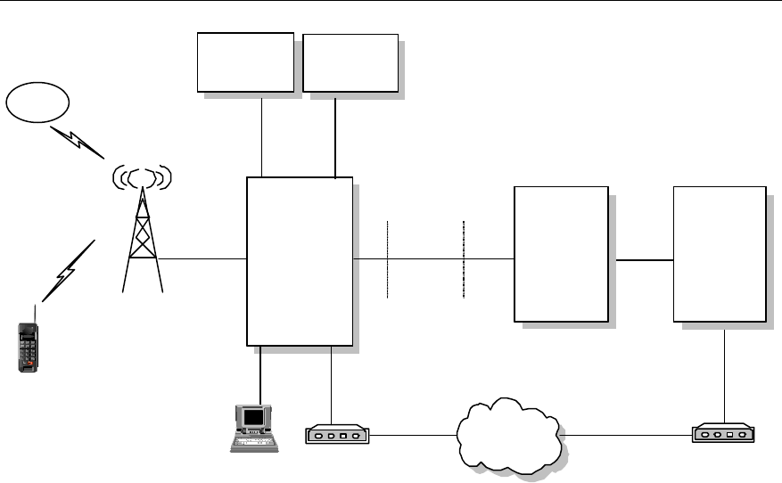
1.4 External Interface
1.4.1 Overview
The external interfaces of cBTS3612 are shown in Figure 1-3.
User Manual
Airbridge cBTS3612 CDMA Base Station System Description
1 System Overview
1-10
BTS
Abis interface
Um
interface
MS
Satellite Synchronization
interface
OML interface
Test
interface
Ethernet
interface Remote maintenance serial port
PSTN
Environment
alarm interface
Environment
alarm box
BSC OMC
LMF MODEM
Test
equipment
Figure 1-3 BTS external interface
l Um interface: interface with MS.
l Abis interface: interface with BSC.
l OML interface: interface with the remote OMC. It shares the transmission
resources with Abis interface.
l LMF interface: interface with BTS local maintenance console.
l System synchronization interface: including GPS/GLONASS antenna interface
and system external synchronization interface. When GPS/GLONASS is not
available and there is other clock synchronization equipment, the clock
synchronization output of the equipment can be connected with the external
synchronization interface of BTS system.
l BTS test interface: interface for BTS test, providing such signals as 10MHz and
2s signal.
l Remote maintenance serial interface: another interface to remote console. This
is a standby maintenance interface can be used when the active maintenance
link between OMC and BTS is interrupted.
l Environment alarm interface: interface with environment alarm collection box.
1.4.2 Um Interface
I. Overview
In Public Land Mobile Network (PLMN), MS is connected with the fixed part of the
network through the radio channel, which enables the subscribers to be connected
User Manual
Airbridge cBTS3612 CDMA Base Station System Description
1 System Overview
1-11
with the network and to enjoy telecommunication services. To implement
interconnection between MS and BSS, systematic rules and standards should be
established for signal transmission on radio channels. The standard for regulating
the radio channel signal transmission is called radio interface, or Um interface.
Um interface is the most important interface among the many interfaces of CDMA
system. Firstly, standardized radio interface ensures that MSs of different
manufacturers are fully compatible with different networks. This is one of the
fundamental conditions for the roaming function of CDMA system. Secondly, radio
interface defines the spectrum availability and capacity of CDMA system.
Um interface is defined with the following features:
l Channels structure and access capacity.
l Communication protocol between MS and BSS.
l Maintenance and operation features.
l Performance features.
l Service features.
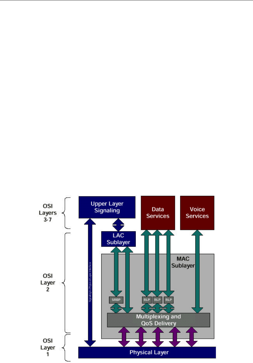
II. Um interface protocol model
Um interface protocol stack is in 3 layers, as shown in Figure 1-4.
Figure 1-4 Um interface layered structure

User Manual
Airbridge cBTS3612 CDMA Base Station System Description
1 System Overview
1-12
l Layer 1 is the physical layer, i.e. the bottom layer. It includes various physical
channels, providing a basic radio channel for the transmission of higher layer
information.
l Layer 2 is the data link layer, including Medium Access Control (MAC) sublayer
and Link Access Control (LAC) sublayer. The cdma2000 MAC sublayer
performs the mapping between logic channels and physical channels, and
providing Radio Link Protocol (RLP) function. The cdma2000 LAC sublayer
performs such functions as authentication, Automatic Repeat Request (ARQ),
addressing and packet organization.
l Layer 3 is the top layer. It performs Radio Resource Management (RM),
Mobility Management (MM) and Connection Management (CM) through the air
interface.
III. Physical layer
1) Operating band
Band Forward Band Reverse Band Duplex
Space
Channel
Wideth
Carrier Space
450MHz 460 - 470MHz 450 - 460MHz 10MHz 1.23 MHz 1.23 MHz
800MHz 869 - 894 MHz 824 - 849 MHz 45MHz 1.23 MHz 1.25 MHz
1900MHz 1930 - 1990 MHz 1850 - 1910 MHz 80MHz 1.23 MHz 1.25 MHz
2) Physical layer function
l Service bearer: the physical channel in the physical layer provides bearer for
the logic channel of the higher layer.
l Bit error check: the physical layer provides a transmission service with error
protection, including error checking and error correction.
l User identification: the physical layer provides an exclusive ID for every user by
code division.
3) Radio configuration
The cdma2000 physical layer supports multiple Radio Configurations (RCs).
Different RCs support different traffic channel data rates. For detailed introduction,
please refer to Section 4.5.4 Radio Configuration and Channel Support.
IV. Data link layer
Data link layer at Um interface includes two sublayers: MAC and LAC. The purpose
of introducing MAC and LAC is to:
l Support higher level services (signaling, voice, packet data and circuit data).
l Support data services of multiple rates.
l Support packet data service and circuit data service of higher quality (QoS).

User Manual
Airbridge cBTS3612 CDMA Base Station System Description
1 System Overview
1-13
l Support multi-media service, i.e. processing voices, packet data and circuit
data of different QoS levels at the same time.
1) MAC sublayer
To support data service and multi-media service, cdma2000 1X provides powerful
MAC layer to ensure the reliability of services. MAC layer provides two important
functions:
l Radio Link Protocol (RLP ), ensuring reliable transmission on the radio link.
l Multiplex function and QoS function, with diversified services and higher service
quality.
2) LAC sublayer
LAC layer performs such functions as Automatic Repeat Request (ARQ),
authentication and addressing.
V. Layer 3
The higher layer signaling performs the functions such as radio resource
management, mobility management and call control management on air interface.
1) Radio resource management
It is mainly used to establish, operate and release radio channels, and help to
realize soft handoff, softer handoff and hard handoff.
2) Mobility management
It is mainly used to support the mobility features of the mobile user, performing such
functions as registration, authentication and Temporary Mobile Subscriber Identifier
(TMSI) re-allocation.
3) Connection management
It is mainly used to setup, maintain and terminate calls.
VI. Power control
Um interface utilizes power control technology to reduce the system interference
and improve the system capacity. There are forward power control and reverse
power control available.
1) Forward power control supports closed-loop power control
Forward power control includes power control based on power measurement report,
control based on EIB, and quick forward power control.
Forward closed-loop power control means that MS checks the quality of received
frames and received power, makes judgment and sends request to BTS for

User Manual
Airbridge cBTS3612 CDMA Base Station System Description
1 System Overview
1-14
controlling BTS transmitting power. Then BTS adjusts its transmitting power
according to the request. Power control command is sent at a rate of 50bit/s or
800bit/s.
2) Reverse power control includes open-loop power control and closed-loop power
control.
l Reverse open-loop power control means that MS adjusts its transmit power as
the received power changes.
l Reverse closed-loop power control means that BTS compares the received MS
transmit power with the preset power control threshold and sends power control
command based on the comparison. MS changes its transmit power as
required by the received power control command. Power control commands are
transmitted on F-TCH at a rate of 800bit/s.
For more information about power control, please refer to Section 4.5.1 Power
Control.
VII. Handoff
Um interface supports many handoff technologies. It supports three types of handoff
in traffic channel communication:
1) Hard handoff: MS breaks the connection with the old BTS before establishing
connection with a new BTS.
2) Soft handoff: MS establishes connection with a new BTS while maintaining the
connection with the existing one.
3) Softer handoff: soft handoff that occurs between different sectors of the same
BTS.
Soft handoff technology can improve the rate of handoff success, reduce call drops
and effectively improve the system performance.
For more information, please refer to Section 4.5.2 Handoff.
1.4.3 Abis Interface
I. Overview
Abis interface is defined as the interface between BSC and BTS, the two functional
entities in the Base Station Subsystem (BSS). It is the interface defined for BTS
accessing BSC via the terrestrial link.
User Manual
Airbridge cBTS3612 CDMA Base Station System Description
1 System Overview
1-15
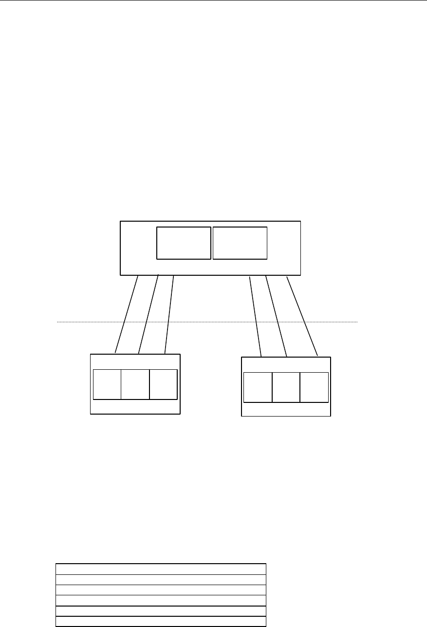
1) Composition of Abis interface
Abis interface consists of three parts: Abis traffic, Abis signaling and OML signaling,
as shown in Figure 1-5.
Abis traffic is the interface connecting SDU of BSC and the channel processing unit
of BTS. It is used to bear user traffic.
Abis signaling is the signaling transmission channel between BSC and BTS. It is
used to control the cell setup, transmission of messages in paging channels and
access channels, and call setup & release.
OML signaling is used to perform operation and maintenance. It is defined by
equipment manufacturers. On Abis interface, there is a transparent channel used to
bear OML between OMC and OMU of BTS.
SPU SDU
Abis Signaling
Abis Signaling
Abis Traffic
Abis Traffic
OML
OML
CEs CEs
BSC
BTS BTS
OMU MC
MC OMU
Abis Interface
SDU:Selection/Distribution Unit
MC
:
Main Control
SPU:Signaling Process Unit CEs: Channel Elements
OMU:Operation & Maintenace Unit
Figure 1-5 Composition of Abis interface
2) Protocol stack of Abis interface
The protocol stack used by Abis signaling and the signaling for operation &
maintenance is as follows:
Abis Signaling Application/OAM Application
TCP
IP
AAL5
ATM
Physical Layer

User Manual
Airbridge cBTS3612 CDMA Base Station System Description
1 System Overview
1-16
Protocol stack used by Abis traffic is as follows:
Abis Traffic
SSSAR
AAL2
ATM
Physical Layer
II. Physical layer
The physical layer of Abis interface can use E1/T1 interface or STM -1 interface.
With E1/T1 interface used, its physical electric parameters comply with CCITT
G.703 recommendations. The multiple E1/T1 trunk lines transmit ATM cells by
means of Inverse Multiplexing on ATM (IMA).
III. Data link layer
ATM is used in the data link layer of Abis interface.
Adaptation of Abis signaling is performed on the basis of AAL5, and is borne in IP
Over ATM (IPoA) mode. At Abis interface, Abis signaling path connects the main
control software (MC) and SPU of BSC via Permanent Virtual Circuit (PVC) to
transmit Abis signaling. So it is with the transmission path of signaling that performs
operation & maintenance. It also uses PVC to connect OMU of BTS and BSC, which
will forward it to OMC transparently. BSC does not process any signaling that
performs operation and maintenance.
Adaptation of Abis traffic is performed on the basis of AAL2. At Abis interface,
BCPM uses several PVCs to connect the channel processing unit of BTS and SDU
of BSC, for BTS to transmit the uplink data received from the air interface to BSC,
and for BSC to transmit the downlink data to be transmitted via the air interface to
BTS.
IV. Layer 3 - traffic management
At Abis interface, Abis signaling and Abis traffic are in the domain of traffic
management. Specifically, Abis traffic management includes the following functions:
1) BTS logic operation & maintenance function
l Resource status indication: with this function, BTS requests logic configuration
from BSC, reports logic status to BSC and checks logic resource regularly.
l Cell configuration: with this function, BSC configures logic parameters of cells
for BTS, including cell pilot Pseudo Noise (PN) offset, sector gain, common
channel number and parameter.
l Overhead message updating: with this function, BSC configures or update
overhead message to BTS.

User Manual
Airbridge cBTS3612 CDMA Base Station System Description
1 System Overview
1-17
l Cell breath control function.
l Cell blocking function.
l Radio measurement report function.
2) Common channel management procedure
Paging channel management procedure: it is used to transmit paging channel
messages from BSC to MSs through Abis interface.
Access channel management procedure: it is used to transmit access channel
messages received on the access channel of BTS to BSC through Abis interface.
3) Procedure of dedicated channel setup and release
It is used to control the setup and release of dedicated radio channel and Abis
interface terrestrial channel.
Abis interface supports the setup and release of various dedicated channels
specified in IS95A/B and cdma2000 1X, specifically including IS95-FCH,
IS95-SCCH, IS2000-FCH, IS2000-DCCH and IS2000-SCH.
Each radio channel is allocated with one AAL2 link on Abis interface to bear user
traffic data.
Caution:
Softer handoff is only allocated with one AAL2 link on Abis interface.
4) Traffic channel bearing procedure
BTS needs to process Abis interface frame protocol, to transmit the data received
from the reverse traffic channel on the air interface to BSC and the data from BSC
through the forward traffic channel at the air interface.
Traffic channel bearing procedure also performs functions such as AAL2 traffic
matching, time adjustment of traffic data frame, reverse outer loop power control
adjustment and forward power control adjustment.
5) Power control
Abis interface supports various power controls. Power control is performed through
parameter configuration. Power control falls into 4 types: quick forward closed-loop
power control, slow forward closed-loop power control, quick reverse closed-loop
power control and reverse open-loop power control.

User Manual
Airbridge cBTS3612 CDMA Base Station System Description
1 System Overview
1-18
1.4.4 OML Interface
OML interface is between BTS and remote OMC. It is actually one of the Abis
interface applications, but in the application layer, OML interface is between BTS
and the remote OMC. OML interface shares resources of Abis interface, including
physical layer, ATM, AAL5 and TCP/IP. For details, please refer to the introduction to
Abis interface.
OML interface is used for OMC to perform operation and maintenance to BTS. It is
defined by equipment manufacturers. On Abis interface, it is a transparent path.
1.4.5 LMF Interface
LMF interface is the interface between BTS and Local Maintenance Function (LMF).
Its interface protocol stack is shown as below:
LMF Signaling Application (self-defined)
TCP
IP
Data Link Layer
Physical Layer (10/100 Base-T)
1.4.6 System Synchronization Interface
System synchronization interface includes GPS/GLONASS antenna interface and
system external synchronization interface.
1) GPS/GLONASS antenna interface: GPS is in compliance with ICD200c:
IRN-200C-001-IRN-200C-004: Interface Control Document of GPS. GLONASS is in
compliance with GPS/GLONASS Receiver Interface Language (GRIL).
2) System external synchronization interface: the external synchronization interface
without GPS/GLONASS is in compliance with the requirement of CDMA Digital
Cellular Mobile Communication Network GPS/GLONASS Dual-Mode Receiver and
Base Station Interface Specifications.
1.4.7 BTS Test Interface
BTS test interface provides 10MHz and 2s signals that may be necessary for
testers.

User Manual
Airbridge cBTS3612 CDMA Base Station System Description
1 System Overview
1-19
1.4.8 Remote Maintenance Serial Port
Remote maintenance serial port is an RS-232 serial port, connected with PSTN via
an external Modem. It is used for emergency maintenance by dial-up with a Modem
when OML between OMC and BTS is interrupted.
1.4.9 Environment Alarm Interface
Environment alarm interface is an RS-485 serial port connected with the external
environment alarm collection box, performing a centralized monitoring to the
environment. A communication protocol defined by Huawei is used between BTS
and the environment alarm collection box. Therefore, supported environment alarm
collection box should be used for the BTS.
1.5 Reliability Design
Reliability design of a system is shown in the stability and reliability of the product
during operation.
Huawei cBTS3612 is designed based on reference to the following standards:
l YD/T 1029-1999 800MHz General Technical Specifications of CDMA Digital
Cellular Mobile Communication Network Equipment
l YD/T 1030-1999 800MHz Technical Requirement for Interface of CDMA Digital
Cellular Mobile Communication Network
l TIA/EIA/IS-97D Minimum Performance Standard of CDMA Base Station
l Huawei product reliability design index and related technical specifications
The design of boards is in strict accordance with the requirement of above
standards pertaining to reliability design, with measures taken to improve the
reliability. In addition, some key parts of the system are designed with redundancy
(such as active/standby mode and resource pool) to improve the reliability of the
system.
System reliability indices are:
MTBF: 100000 hours MTTR: 1 hour A : 99.999%

User Manual
Airbridge cBTS3612 CDMA Base Station System Description
1 System Overview
1-20
&
Note:
Reliability refers to the product capability of performing specified functions in the specified conditions
and specified time.
There are 3 main indices to describe the reliablity of a system:
MTBF: Mean Time Between Failures, normally applicable to recoverable systems.
MTTR: Mean Time To Repair, inlcuding the time of fault checking, isolation, unit replacement and
recovery.
A: Availability , a comprehensive index to measure the system availability.
1.5.1 Hardware Reliability Design
cBTS3612 is designed with substantial hardware reliability, such as board
active/standby operation, load sharing and redundancy configuration. In addition,
system maintainability is improved with fault detection and isolation technology on
the board and system. In respect of hardware reliability, the following considerations
have been taken:
I. De-rating design
To improve system reliability and prolong the service life of components,
components are carefully selected and strictly tested, and less stress (electrical
stress and temperature stress) is to be borne than its designed rating.
II. Redundancy design
Redundant configuration of key units is applied in the BTS system. The system or
equipment will not fail unless the specified sets of units fail. In the BTS system,
common measures such as active/standby and load-sharing modes are adopted,
e.g. for BCIM, BCPM and BCKM.
III. Selection and control of components
The category, specifications and manufacturers of the components are carefully
selected and reviewed according to the requirements of the product reliability and
maintainability. The replaceability and normalization of components is one of the
main factors for the decision, which help to reduce the types of components used
and hence improve the availability of the system.

User Manual
Airbridge cBTS3612 CDMA Base Station System Description
1 System Overview
1-21
IV. Board level reliability design
Many measures have been taken to improve the board reliability. Moreover, the
system reliability is improved through the redundancy design of key parts.
l Key circuits are designed by Huawei, which lays the foundation of high
reliability.
l The hardware WATCHDOG is equipped for the board, and the board can
automatically reset in case of fault.
l The board is provided with the functions of over-current and over-voltage
protection and the function of temperature detection.
l The board also provides emergency serial port, and can keep contact with the
main control board in case of emergency.
l Strict thermal analysis and simulation tests are conducted during the design of
boards for the purpose of ensuring longtime operation.
l The board software and important data is stored in the non-volatile memory, so
that the board can be restarted when the software upgrading fails.
V. Overvoltage and overcurrent protection
The BTS system provides various means of over-voltage and over-current
protection.
l Over-voltage and over-current hardware protection is provided for the DC/DC
power supply module.
l For secondary power supply to boards, slow-start is employed to prevent the
great impact on the whole power supply load when the boards are powered on.
Fuse is installed for each board against over-current.
l For E1 interface circuit, serial-port circuit and network interface circuit,
protection measures are taken in accordance with the corresponding design
specifications of Huawei.
VI. Power supply reliability
The reliability of power supply is improved by means of over-current and
over-voltage protection, internal temperature adjustment, and redundancy backup.
VII. Fault detection, location and removal
The BTS system is equipped with the functions of self-detection and fault diagnosis
that can record and output various fault information. The common software and
hardware faults can be corrected automatically.
The hardware fault detection functions include fault locating, isolating and automatic
switchover. The maintenance engineers can identify the faulty boards easily with the
help of the maintenance console.

User Manual
Airbridge cBTS3612 CDMA Base Station System Description
1 System Overview
1-22
When faults occur to software, certain automatic error-correction function will be
executed, including restarting and reloading.
The BTS system also provides manual and automatic re-initialization of different
levels, and supports the reloading of configuration data files and board execution
programs.
VIII. Fault tolerance
When faults occur, the system usually will not be blocked, as the BTS system
provides the E1 connection in conformity with the IMA protocol, and has certain line
backup capabilities.
The boards of important devices in the system have been backed up, ensuring that
the BTS system can switch the service from the faulty board to a normal board, or
perform reconfiguration of the system.
The system will make a final confirmation on a hardware fault through repeated
detection, thus avoiding the system reconfiguration or QoS deterioration due to
contingent faults.
IX. Thermal design
The influence of temperature on the BTS system has been considered in the design
of the system. Thermal design primarily concerns the selection of components,
circuit design (including error tolerance, drift design and derating design), structure
design and heat dissipation, so that the BTS system can work reliably in a wide
range of temperatures.
The first consideration in thermal design is to balance the heat distribution of the
system. Corresponding measures are taken in the place where heat is more likely to
be accumulated.
X. Maintainability
The purpose of maintainability design is to define the workload and nature of the
maintenance, so as to cut the maintenance time. The main approaches adopted
include standardization, modularization, error prevention, and testability
improvement which can simplify the product maintenance work.
XI. EMC design
The design ensures that cBTS3612 will not degrade to an unacceptable level due to
the electromagnetic interference from other equipment in the same electromagnetic
environment. At the same time, cBTS3612 will not cause other equipment in the

User Manual
Airbridge cBTS3612 CDMA Base Station System Description
1 System Overview
1-23
same electromagnetic environment to degrade to an unacceptable level due to the
EMI from it.
XII. Lightning protection
To eliminate the probability of lightning damage on the BTS system, proper
measures are taken in the following three aspects:
l Lightning protection for DC power supply
l Lightning protection for BTS trunk lines
l Lightning protection for antenna and feeder system
For details, please refer to "2.7 Lightning Protection System".
1.5.2 Software Reliability Measures
Software reliability mainly includes protection performance and fault tolerance
capability.
I. Protection performance
The key to improve software reliability is to reduce software defects. Software
reliability of BTS is ensured in the whole process from system requirement analysis,
system design to system test.
Starting from the requirement analysis, software development process goes under
regulations such as CMM (Capability Mature Mode), which aim to control faults in
the initial stage.
In software design, much attention is devoted to the designing method and
implementation: the software is designed in a modular structure, and in a loose
coupling mechanism. When a fault occurs to one module, other modules will not be
affected. In addition, preventive measures such as fault detection, isolating and
clearing are also important in improving the system reliability. Other effective
methods include code read-through, inspection, and unit test.
Various software tests are necessary to improve the software reliability. Test
engineers participate the whole software develop process, from unit test to system
test. They make plans strictly compliant with the demand of the upper level flow,
which ensure the improvement of software reliability. Additionally, test plans are
improved with the tests and become more and more applicable.
II. Fault tolerance capability
Fault tolerance capability of the software system means that the whole system
would not collapse when a minor software fault occurs, i.e. the system has the

User Manual
Airbridge cBTS3612 CDMA Base Station System Description
1 System Overview
1-24
self-healing capability. The fault tolerance of software is represented in the following
aspects:
l All boards work in a real-time operating system of high reliability.
l Important data on BCKM are backed up on real-time basis. Operation is
switched to the standby board when a fault occurs.
l When a fault occurs to some transmission links, traffic borne on them can be
transferred to other links smoothly.
l Each board's software on the board has a static backup on BCKM.
l If software loading fails, the system can return to the version that was loaded
successfully last time.
l Important operations are recorded in log files.
l Different authority levels are provided for operations, to prevent users from
performing unauthorized operations.
l Prompts are given for the operations that will cause system reboot (such as
reset operation), which requests the operator to confirm it before executing
such operation.
User Manual
Airbridge cBTS3612 CDMA Base Station System Description
2 Hardware Architecture
2-1
2 Hardware Architecture
The beginning of this chapter briefs cBTS3612 hardware architecture, followed by
the details of four subsystems: baseband, RF, antenna & feeder, and power supply
system. This chapter also covers BTS environment monitoring and lightning
protection systems.
2.1 Overview
In cdma2000 1X mobile communication system, BTS functions as a radio relay. One
end is connected with MS through Um interface and the other end connected with
BSC through Abis interface.
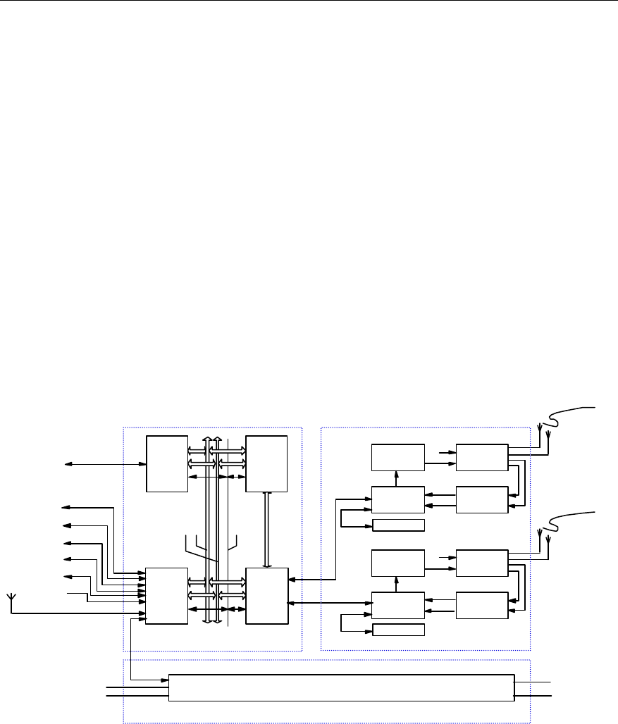
The architecture of BTS is as shown in Figure 2-1.
Abis interface
High-speed data bus
BCIM
BSC
Clock bus
Backplane
bus
Emergency
serial port
POWER
RS485
Um interface
RF receive/ transmit
antenna
BCKM
Baseband
subsystem RF subsystem
Power supply
subsystem
-48VDC
GND
+27VDC
GND
GPS/GLONASS receive antenna
LMF
Environment alarm
collection
Ethernet port
RS485
RS485
RS232
Modem
BFMM
Test
equipment
Test interface
External
synchronization
BCPM
BRDM BTRM
BHPA
BTRM
BHPA CDU
RLDU
BBFM
RS485
Optical fiber
BTRM
BHPA CDU
RLDU
BBFM
RS485
Optical fiber
...
BHPA RF receive/ transmit
antenna
Um interface
Figure 2-1 BTS architecture

User Manual
Airbridge cBTS3612 CDMA Base Station System Description
2 Hardware Architecture
2-2
&
Note:
In Figure 2-1, the duplexer is CDU, and actually the right duplexer should be selected according to the
band class BTS supported. CDU applies to 800MHz band and 450MHz band, DFU applies to
450MHz band, and DDU applies to 1900MHz band, as for the difference between the CDU, DFU and
DDU, please refer to "2.3 RF Subsystem".
BTS is mainly composed of baseband subsystem, RF subsystem, antenna & feeder
subsystem (which comprises RF receive/transmit antenna and GPS/GLONASS
receive antenna) and power supply subsystem. Baseband subsystem in physical
structure also carries a clock synchronization unit, receiving GPS/GLONASS clock
and providing system time, synchronous clock and frequency reference.
I. Baseband subsystem
The main functions of baseband subsystem are: processing Abis interface protocol,
modulating/demodulating baseband data, channel encoding/decoding, processing
protocols of physical layer and MAC layer on air interface, system
operation/maintenance and connecting baseband data optical interface of RF
module.
Baseband subsystem is located in the BTS baseband subrack. It consists of BTS
Control & Clock Module (BCKM), BTS Resource Distribution Module (BRDM), BTS
Channel Processing Module (BCPM), BTS Control Interface Module (BCIM) and
CDMA Baseband Backplane Module (CBKM). Functions of all boards are
highlighted as follows:
1) BCKM
At most 2 BCKMs are configured in hot standby. BCKM receives GPS signals (or
other synchronization satellite signals), generates local clock and provides time
signals 16%1.2288MHz, 10MHz, PP2S for the boards in the system. This is mainly
the responsibility of the clock module of BCKM. Besides clock signal, BCKM also
provides main control function for channel resources. Its MPU module performs a
number of operations and functions such as resource management, equipment
management, performance monitoring, configuration management, software
downloading, MPU active/standby switchover, operation & maintenance (O&M),
environment monitoring interface, as well as board control inside the system.
2) BRDM
BRDM is logically located between BTRM and BCPM. The data sent by BTRM
module are sent to BRDM via the optical fiber. Then BRDM distributes the data
before sending them to BCPMs via the high-speed data bus. BRDM can also build

User Manual
Airbridge cBTS3612 CDMA Base Station System Description
2 Hardware Architecture
2-3
daisy chains for BCPMs. The BRDM connects via the shorter daisy chain provided
to BCPM to form a standard daisy chain, which helps to improve the utilization ratio
of channel resource and facilitates the flexible configuration of channel capacity for
each sector carrier. BRDM exchanges O&M information with BCKM through the
backplane bus. The emergency serial port of BRDM is attached on the UART of the
backplane as a standby node.
3) BCPM
BCPM processes BTS baseband signals, both for the forward traffic and reverse
traffic. For forward traffic, it performs functions such as encoding (convolutional code,
TURBO code), interleaving, spectrum spreading, modulation and data multiplexing.
For reverse traffic, it performs functions such as demultiplexing, demodulation,
de-interleaving and decoding (convolutional code, TURBO code). Regarding the
user data flow, BCPM is between BRDM and BCIM.
4) BCIM
BCIM transfers data between BTS and BSC, including voices, data and O&M
commands. With the Inverse Multiplexing on ATM (IMA) technology, BCIM
multiplexes the BTS uplink data to IMA link set that is composed of multiple E1s,
and then transmits it to BSC via coaxial or optical fiber. Inversely, it can also
demultiplex the IMA link set signals from BSC into an ATM cell flow and transmit it to
BTS boards via the backplane bus.
5) CBKM
CBKM performs interconnection of high-speed data links between boards in the
baseband part and the interconnection of various management and control signals
of boards.
II. RF subsystem
BTS RF subsystem is composed of five parts: BTS Transceiver Module (BTRM),
BTS High Power Amplifier Module (BHPA), BTS Transceiver Backplane Module
(BTBM), Duplexer Unit and Receive LNA Distribution Unit (RLDU). Functions of all
parts are briefed as follows:
1) BTRM
BTRM consists of BTS Intermediate Frequency Unit (BIFU), and BTS Radio
up/down-conversion Unit (BRCU). Its functions are as follows:
BIFU: BIFU performs such functions as A/D conversion in the reverse receiving path
and D/A conversion in the forward transmitting path, digital frequency up/down
-conversion, received signal filtering, baseband molded signal filtering, Digit
Automatic Gain Control (DAGC), uplink & downlink RF Automatic Gain Control

User Manual
Airbridge cBTS3612 CDMA Base Station System Description
2 Hardware Architecture
2-4
(AGC), multiplexing/demultiplexing of forward & reverse orthogonal (IQ) signals,
clock recovery and RF module operation & maintenance.
BIFU also performs the control over BTRM, including power-on initialization,
function configuration, alarm collection and reporting, and processing of O&M
related messages.
BRCU: BRCU is composed of 5 logic functional units: main/diversity transmit unit,
main/diversity receive unit and frequency source unit.
l Transmit unit realizes analog up-conversion and spurious suppressed filtering
for transmitted signals output by BIFU.
l Main/diversity receive unit realizes analog frequency down-conversion, channel
selective filtering and received nose coefficient control for BTS main/diversity
received signals output by RLDU.
l Frequency source unit is responsible for the synthesis of the low phase noise,
high-stability local oscillation signals that are necessary for the analog
frequency conversion in transmit and receive paths.
2) BHPA
BHPA performs high power linear amplification for a transmitted carrier signal,
checks its own working status in real time and generates alarm. It is composed of
main signal power amplification unit and signal detection alarm unit. Signal detection
is to check whether the input is too excited, whether the temperature is too high or
whether the gain is lowered strikingly (device failure).
3) BTBM
BTBM performs structure support and signal communication between BTRM and
BHPA.
4) Duplexer Unit
There are following three types of Duplexers. They can be configured according to
actual requirements.
Combiner and Duplexer Unit (CDU): combining and filtering of two transmitting
carriers, transmitting and receiving signals duplexing and isolating, and diversity
receiving signal filtering. CDU operates at 800MHz band and 450MHz band.
Duplexer and Filter Unit (DFU): transmitting and receiving signal duplexing, isolating
and filtering of one channel, diversity receiving signal filtering. DFU operates at
450MHz band.
Dual Duplexer Unit (DDU): transmitting and receiving signals duplexing, isolating
and filtering of two channels, It does not provide combining function. DDU operates
at 1900MHz band.

User Manual
Airbridge cBTS3612 CDMA Base Station System Description
2 Hardware Architecture
2-5
6) RLDU
RLDU performs low noise amplification and division of the receiving signals,
providing standing wave alarm and forward power checking voltage output, checking
the physical connection of the antenna port and monitoring whether the output of
BRCU, BHPA signals is normal.
III. Antenna & feeder subsystem
BTS antenna & feeder subsystem includes two parts: RF antenna & feeder and
dual-satellite synchronization antenna & feeder. The former mainly transmits the
modulated RF signals and receives MS information while the latter provides precise
synchronization for CDMA system.
IV. Power supply subsystem
Power supply subsystem consists of power input component (EMI filter, lightning
arrester of power supply), high power DC/DC power supply module, power
distribution box, medium/low power DC/DC power supply module for boards (or
modules).
The power supply subsystem provides power for the whole BTS.
2.2 Baseband Subsystem
2.2.1 Overview
The baseband subsystem is one of the major parts of BTS. Its structure is shown in
Figure 2-2.
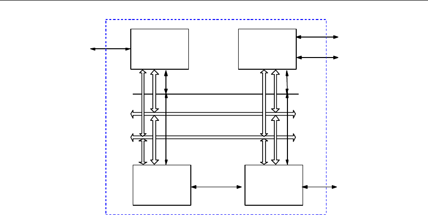
User Manual
Airbridge cBTS3612 CDMA Base Station System Description
2 Hardware Architecture
2-6
High-speed
data bus
BCIM
BSC
BRDM
BCKM
BCPM BTRM
Other functional
units
E1
Optical fiber
Clock bus
Backplane bus
Emergency serial port
...
Figure 2-2 Structure of baseband subsystem
Baseband subsystem is connected with BSC through Abis interface provided by
BCIM. The transmission in this subsystem is performed through E1 trunk (The
coming version will provide STM-1 optical transmission). BRDM and BTRM are
connected by optical fiber to support RF module extended afar mode.
Baseband subsystem also provides some other interfaces through BCKM:
l LMF interface: 10/100 Base-T interface, connecting Local Maintenance
Function (LMF).
l Remote maintenance serial port: The interface is an RS232 serial port,
connected with PSTN via an external Modem. When OML between OMC and
BTS is interrupted, maintenance can be performed through telephone line
dial-up connection.
l GPS/GLONASS antenna interface: It is used to receive clock signal from
GPS/GLONASS.
l System external synchronization interface: When GPS/GLONASS is not
available, it makes the system clock synchronized with external clock.
l Fan module interface: It is connected with fan module through RS485 serial
port, monitoring the fan module.
l Environment alarm interface: It is connected with an external environment
alarm collection box, providing environment monitoring alarm information of the
equipment and monitoring information of the primary power supply.
l Power monitoring interface: It is connected with power supply module, reporting
various alarm information of the power supply.
l Test interface: It is an interface for BTS test, providing 10MHz and 2s signals.
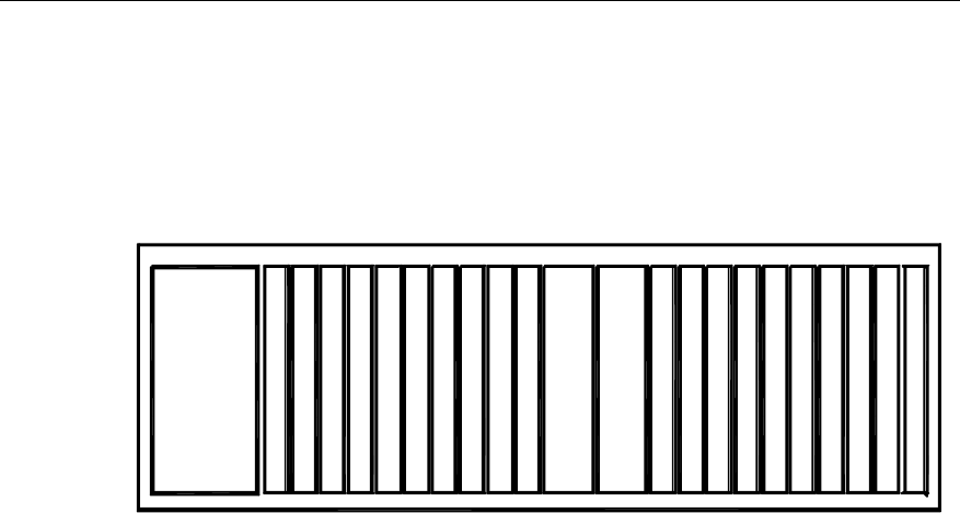
User Manual
Airbridge cBTS3612 CDMA Base Station System Description
2 Hardware Architecture
2-7
Baseband subsystem is physically located in the baseband subrack, powered by
power supply subsystem (in the power subrack). Boards generate their own 3.3V,
1.8V power through the distributed power supply module.
The configuration of baseband subrack (including board position) is as shown in
Figure 2-3.
0
B
C
I
M
1
B
C
I
M
2
B
C
P
M
3
B
C
P
M
4
B
C
P
M
5
B
C
P
M
6
B
C
P
M
7
B
C
P
M
8
B
R
D
M
B
R
D
M
B
C
K
M
B
C
K
M
B
R
D
M
B
R
D
M
B
C
P
M
B
C
P
M
B
C
P
M
B
C
P
M
B
C
P
M
B
C
P
M
B
R
D
M
B
R
D
M
10 11 12 13 14 15 16 17 18 19 20 219
Figure 2-3 Baseband subrack configuration
Baseband subrack supports the following boards:
l BCIM: BTS control interface module, to be inserted in E1 interface slot,
providing Abis interface for connection with BSC and supporting E1/T1
transmission. In the coming version, BCIM slot can also accommodate BEOM
(BTS Electric-Optical Module) to support STM-1 optical transmission.
l BCPM: BTS channel process board, processing the data of CDMA forward
channel and reverse channel.
l BRDM: BTS resource distribution module, connecting BCPM and RF module,
realizing the control of resource pool for BCPM.
l BCKM: BTS control & clock board, providing clock for BTS system and realizing
the control of BTS system resource.
2.2.2 Control & Clock Module (BCKM)
I. Overview
BCKM is located in the baseband subrack of BTS. BCKM performs two major
functions: main control module (MPU, Main Processing Unit) and clock module (CLK,
Clock) functions. Here MPU performs Abis interface signaling processing, O&M
management, while CLK provides reference clock signals for the whole BTS system.
Main functions of BCKM:
l MPU module provides BTS system with a hardware control platform, on which
the operating system and system software are running to implement control
and management tasks of BTS system.

User Manual
Airbridge cBTS3612 CDMA Base Station System Description
2 Hardware Architecture
2-8
l Perform operation and maintenance via the backplane bus for other boards in
the baseband subrack, realizing in-band signaling communication.
l Connected with Local Maintenance Function (LMF) through the 10/100M
compatible Ethernet interface.
l The active/standby asynchronous serial port serves as a path for out-band
signaling backup. MPU functions as the main node and other boards function
as the standby nodes. When a fault occurs to the in-band signaling path,
signaling communication can be maintained with this standby path.
l Provide an interface connected with Modem in compliance with RS232 serial
communication standard, realizing remote maintenance and monitoring in case
of OML link failure.
l Connected with an external monitoring module in compliance with RS485
standard, collecting and processing the equipment room environment
information (such as fire alarm/water soaking/temperature/humidity).
l CLK unit is the clock source of BTS system, providing working clock for all
boards. It provides high precision oscillation clock and can be synchronized
with an external clock (such as GPS clock).
l BCKM provides active/standby switchover function, working in active/standby
mode in the system. When a fault occurs to the active BCKM, the standby
BCKM is switched to active status under the control of specific software. A fault
occurring to either MPU or CLK module of the BCKM will result in the
switchover of the whole BCKM.
II. Structure and principle
The structure of BCKM module is as shown in Figure 2-4.
Power supply
module
External
communication
unit
Clock module
Backplane bus
module
Other
functional units
MPU module
BCKM
CBKM
...
Backplane
bus
Figure 2-4 Structure of BCKM module

User Manual
Airbridge cBTS3612 CDMA Base Station System Description
2 Hardware Architecture
2-9
BCKM comprises the following parts:
1) MPU module
MPU controls logic circuits to initialize components. It realizes control and
management over BTS system through system software.
2) Clock module
Clock module is the clock source of BTS, providing working clock for boards. Clock
module is available in two modes: external synchronization mode (locked mode) and
free oscillation mode (holdover mode). The clock module can provide high-precision
oscillation clock (voltage control constant temperature crystal oscillator) or be
synchronized with external clock source (GPS, GLONASS, external synchronization
equipment).
3) Backplane bus module
The communication port of the Central Processing Unit (CPU) is connected with
other boards of BTS through the backplane bus module, processing or transmitting
O&M signaling from other boards of BTS (BRDM, BCPM and BCIM).
4) External communication module
External communication module utilizes the multiple communication control ports
provided by the main control CPU to implement functions such as LMF interface,
external monitoring module interface, debugging interface, and out-of-band
signaling serial port.
5) Power supply module
BCKM includes two isolated secondary power supply modules, converting +27V
voltage into +5V, +3.3V and +2.5V for various modules of local board.
III. Interface
l LMF interface (10/100 Base-T)
l Remote maintenance serial port (RS232)
l Environment alarm interface (RS485)
l GPS/GLONASS antenna port
l 2s and 10MHz test port
l Inter-board interface, and interfaces with other boards in the baseband subrack.
IV. Index
The board size is 460mm%233.35mm, powered with +27V, power consumption
<20W.

User Manual
Airbridge cBTS3612 CDMA Base Station System Description
2 Hardware Architecture
2-10
2.2.3 Control Interface Module (BCIM)
I. Overview
BCIM is located in BTS baseband subrack. It is a functional entity for the connection
of BTS and BSC. Its major functions are as follows:
l In uplink direction, backplane bus receives O&M command from BCKM and
traffic data from BCPM, and transmit ATM cells on the multiple E1 links with
IMA technology in compliance with G.804 standards to BSC.
l In downlink direction, it receives ATM cells distributed on the multiple E1 links
from BSC, multiplexes them into a single ATM cell flow with IMA technology
and finally sends them to corresponding processing boards through the
backplane bus.
l Each BCIM provides 8 E1 links, which can support at most 4 IMA link sets. In
BTS, there are two BCIMs, providing physical interfaces to BSC in load sharing
mode. At most 16 E1 links can be provided.
l It communicates with BSC through IMA state machine program on the local
board, and monitors the working status of E1 link and ensuring the
implementation of IMA protocol.
l It transmits O&M command through backplane bus or out-band signaling serial
port, reports the status information of the local board to BCKM and provides
interface for board maintenance and network management.
II. Structure and principle
The structure of BCIM is as shown in Figure 2-5.
Backplane
bus module CPU module
Control bus
Data bus
E1
RS232
Backplane
bus
BCKM
BESP
IMA module
...
Power supply
module
Clock module
Figure 2-5 Structure of BCIM module

User Manual
Airbridge cBTS3612 CDMA Base Station System Description
2 Hardware Architecture
2-11
BCIM comprises the following parts:
1) IMA module
The purpose of IMA is to inversely multiplex an ATM cell flow based on cells into
multiple physical links for transmission. Another purpose is to remotely multiplex the
cell flows transmitted on different physical connections into a single ATM cell flow.
In uplink direction, IMA module receives AAL2 traffic cells from BCPM and AAL5
signaling cells from BCKM through the backplane bus. It splits the ATM cell flow into
cells, transmits them on multiple E1 link according to G.804 standard before sending
them to BSC.
In downlink direction, it receives ATM cells from BSC that are distributed on multiple
E1 trunk lines, inversely multiplexes them into a single ATM cell flow. Then it sends
AAL2 traffic cells to BCPM and AAL5 signaling cells to BCKM through the backplane
bus
2) CPU module
The main control CPU on BCIM implements such functions as initialization of
devices on BCIM, IMA protocol processing, executing OAM function of IMA, as well
as E1 trunk line management and communication with BCKM.
3) Backplane bus module
BCIM communicates with other boards in the baseband part through the backplane
bus module, including control information communication with BCKM and traffic data
communication with BCPM.
4) Power supply module
The power supply module implements DC/DC power conversion from +27V to 3.3V.
5) Clock module
It provides working clock for the local board.
III. Interface
l E1 interface
Interface with BSC
l Backplane bus interface
Interface with other boards in the bas eband part.
l RS-232 serial port
As an emergency serial port, it is connected with UART as a standby node, used for
communicating with BCKM when other part of the board is faulty.

User Manual
Airbridge cBTS3612 CDMA Base Station System Description
2 Hardware Architecture
2-12
IV. Index
The board size is 460mm%233.35mm, powered with +27V, power
consumption<10W.
2.2.4 Channel Processing Module (BCPM)
I. Overview
BCPM is logically located between BRDM and E1 interface board on BTS. BCPM is
the service processing board of the system with 12 equipped in full configuration.
Data of various forward channel traffic and reverse channel traffic are processed by
this board. BCPM also processes digital signals, including encoding/decoding
baseband signals and one-time modulation and demodulation of baseband signals.
In addition, it processes high layer control signals. The main functions are as
follows:
l In forward direction, after ATM cell data from the network side are processed by
the high performance processor, BCPM performs functions such as encoding
(convolutional code, TURBO code), interleaving, spread spectrum, modulation
and data multiplexing, and converts them into high-speed signals. Then the
signals are processed by a dedicated processing chip and transmitted through
the radio interface side of the channel processing board.
l In reverse direction, data received by BCPM are demultiplexed, demodulated,
de-interlaced and decoded (convolutional code, TURBO code). Then under the
control of the high performance processor, the data are sent to BSC via E1
interface in the form of ATM cells.
l BCPM supports in-board and inter-board daisy chains, forming a
resource-processing pool.
l High performance processor, two kernels, internal cache, level-2 cache can be
attached externally at the same time to improve processing capacity.
II. Structure and principle
BCPM module comprises the following parts as shown in Figure 2-6:
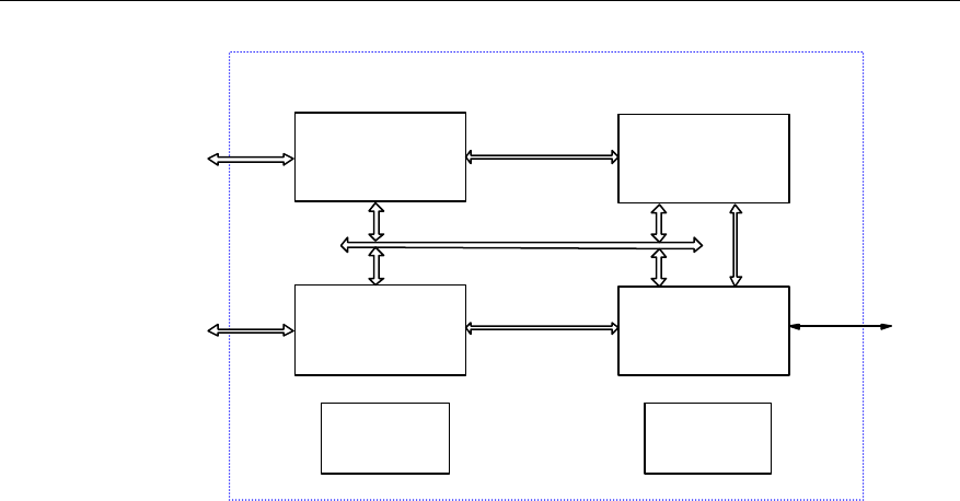
User Manual
Airbridge cBTS3612 CDMA Base Station System Description
2 Hardware Architecture
2-13
Multiplex/demultiplex
module
Baseband
processing module
CPU module
Backplane bus
module
Power module
BCPM
Control bus
Clock module
BRDM Data bus
Data bus
Backplane
bus
RS232 BCKM
High-speed
data bus
Figure 2-6 Structure of BCPM module
1) Multiplex/demultiplex module
In forward direction, baseband data in the channel processing board are multiplexed
into high-speed signals and sent to radio side in the form of differential signals. In
reverse direction, the high-speed differential signals are demultiplexed and sent to
baseband processing chip.
2) Baseband processing module
The QUALCOMM new generation processing chip is used to perform forward and
reverse baseband data processing. With the help of in-board and inter-board data
daisy chains, channel processing capability is increased greatly. Maximal 6 sectors
can be supported.
3) CPU module
The high performance control CPU on BCPM mainly processes the forward &
reverse high-speed traffic data and control data and reports board status. At the
network side, the processing module receives control signaling, receives/transmits
ATM cells and communicates with BSC through E1 interface. At the radio side, it
controls the dedicated baseband processing chip to generate orthogonal (IQ) data.
After multiplexing, the data pass BRDM as high-speed differential signals, to
implement data exchange with radio side.

User Manual
Airbridge cBTS3612 CDMA Base Station System Description
2 Hardware Architecture
2-14
4) Backplane bus module
BCPM communicates with other boards in the BTS baseband part through
backplane bus, including control information communication with BCKM and traffic
data communication with E1 interface board.
5) Clock module
The clock module performs double-frequency phase-locking to the clock signals
from the backplane, provides clock for boards, and drives and co-phases the clock
signals generated on the local board, to get satisfactory clock signals.
6) Power supply module
It performs DC/DC power conversion from +27V to 3.3V.
III. Interface
l High-speed data bus interface
Interface with BRDM.
l Backplane bus interface
Interface with other boards of baseband part
l RS232 serial port
As an emergency serial port, it is connected with UART as a standby node, used for
communicating with BCKM when other part of the board is faulty.
IV. Index
The board size is 460mm%233.35mm, powered with +27V, power consumption
<30W.
2.2.5 Resource Distribution Module (BRDM)
I. Overview
BRDM is logically located between BTRM and BCPM, providing path for orthogonal
data connection (IQ) and exchange between the two so as to support the flexible
configuration relation between BCPM and BTRM. BRDM also support daisy chain
cascading between BCPMs.
Data from BTRM are sent to BRDM through optical fiber. BRDM distributes the data
before sending them to BCPMS via the high-speed data bus. BRDM can also build
daisy chains for BCPMs. BRDM connects via the short daisy chain provided to the
BCPM to form standard daisy chain. This can help to improve the utilization ratio of
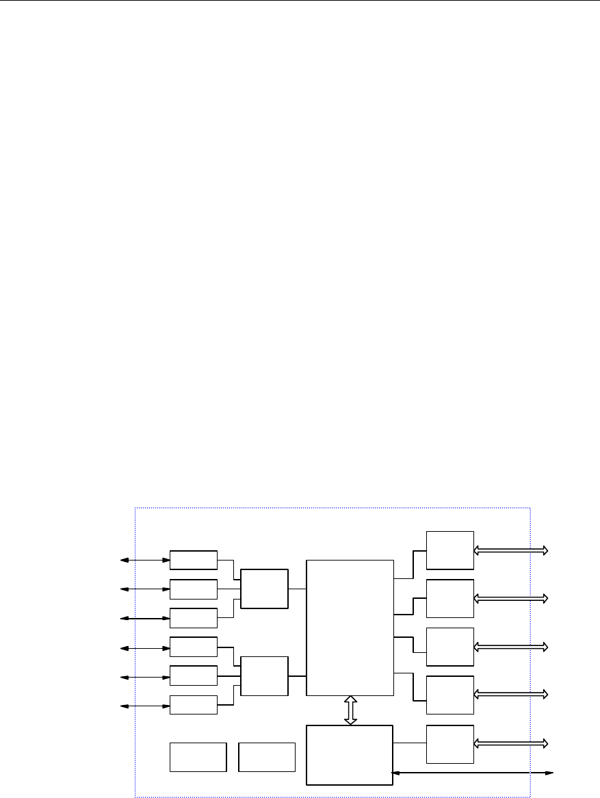
User Manual
Airbridge cBTS3612 CDMA Base Station System Description
2 Hardware Architecture
2-15
channel resource and facilitates the flexible configuration of the channel capacity of
each sector carrier.
BRDM has the following functions and features:
l Six pairs of optical interfaces provide high-speed data paths to BTRM.
l When it is necessary to extend optical interfaces, BRDM board can be inserted
in BCPM slot.
l 16 pairs of high-speed data bus interfaces are prvoded for connection with 16
BCPM slots through the backplane.
l Flexible data distribution and exchange between BTRM and BCPM are
enabled.
l Flexible data exchange between BCPMs is enabled. It can be cascaded to form
daisy chains, so BCPM resource pool can be achieved. Resource pool
improves the utilization ratio of channel resource and makes the configuration
of channel capacity of each sector carrier flexible.
l It exchanges O&M information with BCKM through the backplane bus or
emergency serial port.
l It forwards and receives O&M information of BTRM via optical fiber and
provides O&M link between the baseband subrack and BTRM.
II. Structure and principle
The structure of BRDM module is as shown in Figure 2-7.
Optical
module
High-speed
data
interface
Switching
module
CPU
module
Bus
interface
module
4 high-speed
data buses
Power supply
module
Optical
Optical
Optical
Optical
Optical
Optical
Clock
module
Optical
module
Optical
module
Optical
module
Optical
module
Optical
module
High-speed
data
interface
High-speed
data
interface
RS232
BTRM BCPM
Backplane
bus
BCKM
BCPM
BCPM
BCPM
BTRM
BTRM
BTRM
BTRM
BTRM
BRDM
High-speed
data
interface
High-speed
data
interface
High-speed
data
interface
4 high-speed
data buses
4 high-speed
data buses
4 high-speed
data buses
Figure 2-7 Structure of BRDM module

User Manual
Airbridge cBTS3612 CDMA Base Station System Description
2 Hardware Architecture
2-16
As shown in Figure 2-7, BRDM board is composed of optical module, high-speed
data interface module, switching module, CPU module, bus interface module, power
supply module and clock module.
l Optical module
This module converts optical signal into electrical signal.
BRDM can be classified into single-mode BRDM and multi-mode BRDM according
to different type of optical module. The single-mode BRDM can be further classified
into two kinds, namely 10km and 70km, according to the transmission capability of
the optical module.
The multi-mode BRDM is used to connect with BTRM in the cabinet, while the
single-mode BRDM is used to cascade SoftSite (ODU3601C).
Equipped with 6 optical modules, the multi-mode BRDM provides 6 pairs of optical
fiber ports. Equipped with 3 optical modules, the single-mode BRDM provides 3
pairs of optical fiber ports.
l High-speed data interface module
High-speed data interface module mainly performs rate conversion of high-speed
signals, for the convenient processing of the switching module.
l Switching module
Switching module segments and paste data as required. It is a core processing
module of this board. Data from BTRM are sent to this board, where the switching
module will distribute and paste them before sending to BCPM. The switching
module can also provide daisy chain cascading for the BCPMs through the
distribution and pasting of data.
l CPU module
CPU module processes O&M information and configures switching parameters. The
O&M information from BCKM is sent to this board via the bus interface module.
Then CPU module processes the information and sends the necessary O&M
information to the corresponding BTRMs. The parameters of the switching module
should also be configured by CPU module.
l Bus interface module
This module performs conversion of interface between the board and the backplane,
and provides a path for the O&M information between this board and the backplane.
l Power supply module
This module converts the input DC +27V power into digital +3.3V, +1.8V and analog
+3.3V powers for the modules on the local board.

User Manual
Airbridge cBTS3612 CDMA Base Station System Description
2 Hardware Architecture
2-17
l Clock module
The clock module provides 2S, 16%1.2288MHz, 100%1.2288MHz clocks for the local
board.
III. Interface
l Optical interface
They are on the front panel, 6 pairs altogether. They are connected with BTRMs,
transmitting orthogonal (IQ) data and O&M information.
l High-speed data interface
The interfaces are connected with 16 service slots through the backplane, for
transmitting orthogonal (IQ) data.
l Backplane bus interface
It is used for transmitting O&M information between the BCKMs.
l Clock interface
It is connected with BCKM via the backplane. It receives 2S, 16 %1.2288MHz clock
signals and clock active/standby selection signal.
l RS232 serial port
As an emergency serial port, it is connected with UART as a standby node, used for
communicating with BCKM when other part of the board is faulty.
l Power interface
Led out from the power connector on the backplane, the interface is connected with
+27V power, +27V power ground and PGND.
IV. Index
The board size is 460mm%233.35mm, powered with +27V, power
consumption<45W.
2.2.6 Baseband Backplane Module (CBKM)
I. Overview
CBKM is used to make interconnection of high-speed data links among the boards
of baseband part, and exchanges various management and control information of
boards with high-speed backplane technology.
Specifically, the backplane:
l Realizes interconnection of various signals between boards.
l Supports hot plug/unplug of all boards.
l Supports active/standby switchover of BCKM.

User Manual
Airbridge cBTS3612 CDMA Base Station System Description
2 Hardware Architecture
2-18
l Leads in system power and provides distributed power to all boards.
l Leads in the signal monitoring line for fan subrack and power subrack.
l Provides protection against misplug.
II. Structure
Functional units in CBKM are as shown in Figure 2-8.
0
B
C
I
M
1
B
C
I
M
2
B
C
P
M
3
B
C
P
M
4
B
C
P
M
5
B
C
P
M
6
B
C
P
M
7
B
C
P
M
8
B
R
D
M
B
R
D
M
B
C
K
M
B
C
K
M
B
R
D
M
B
R
D
M
B
C
P
M
B
C
P
M
B
C
P
M
B
C
P
M
B
C
P
M
B
C
P
M
B
R
D
M
B
R
D
M
10 11 12 13 14 15 16 17 18 19 20 219
Figure 2-8 Functional units of all slots in CBKM
A backplane includes the connector and board slot.
Connector part includes a slot for test board, input connector of backplane +27V
power/ground, and 3 DB37 D-connectors. Power input connector, D-connector are
all crimped devices.
Slots of the backplane are defined as follows:
l Slots 0~1 are for BCIMs.
l Sots 10~11 are for BCKMs.
l Slots 8~9, 12~13, 20~21 are for BRDMs.
l Slots 2~7, 14~19 are for BCPMs.
III. Interface
The interfaces between the backplane and external devices include:
l System power interface
l Remote maintenance serial port
l Environment alarm interface
l Fan alarm serial port in baseband subrack
l System external synchronization interface
l 16 E1 interfaces
IV. Index
CBKM size: 664mm%262mm.
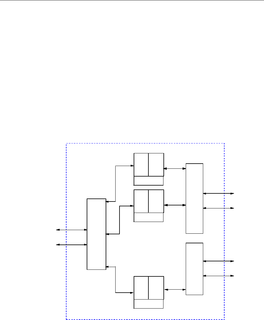
User Manual
Airbridge cBTS3612 CDMA Base Station System Description
2 Hardware Architecture
2-19
2.2.7 E1 Surge Protector (BESP)
I. Overview
BESP is placed in the upper part of BTS. It is a functional entity for BTS to
implement lightning protection with E1 trunk line. Two identical BESPs are installed
for each cabinet in consideration of limited space on top of the equipment and the
convenience of installation and dismounting. The 8 pairs of lightning protection units
are used to discharge the transient high voltage on the sheath and core of E1 trunk
line to PGND.
II. Structure and principle
Board structure is as shown in Figure 2-9.
8 E1s
4 E1s
4 E1s
Interface
DB37
BSC
Interface
DB25
Interface
DB25
BESP
...
BSC
...
BCIM
...
...
Level-1
protection
Level-2
protection
PGND
Level-1
protection
Level-2
protection
PGND
Level-1
protection
Level-2
protection
PGND
Figure 2-9 Structure of BESP
The board consists of three parts: DB25 connector, lightning protection unit and
DB37 connector.
When the BTS E1 trunk line is struck by the lightning, high voltage will arise first on
DB25. The high voltage will spread to the lightning protection units. The lightning
protection units have two protection levels: air discharge tube and voltage limit mesh.

User Manual
Airbridge cBTS3612 CDMA Base Station System Description
2 Hardware Architecture
2-20
The air discharge tube discharges the high voltage to the ground and lowers the
voltage to less than 600V. Then the voltage limit mesh further lowers the voltage to
less than 30V.
III. Interface
l E1interface
Interface with BSC (DB25).
Connection with BCIM (DB37)
IV. Index
Board size: 140mm%120mm
Bearable surge current: >10kA (common mode), >5KA (differential mode)
Output residual voltage: <30V.
2.2.8 Fan Module (BFAN)
BFAN is installed right under the baseband subrack, serving as a part of the blower
type cooling system of the baseband subrack. The fan module consists of two fan
boxes, each of which has 4 fan units (24V DC brush-free fan), and one BTS Fan
Monitor Module (BFMM). Fan enclosure is used for installation of fan boxes. The
outside of the fan enclosure is the BTS Fan Block Interface Board (BFNB) that
provides a system interface. The structure of BFAN is as shown in Figure 2-10.
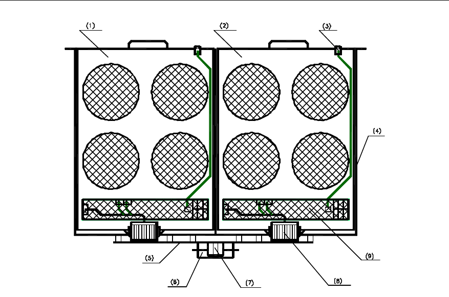
User Manual
Airbridge cBTS3612 CDMA Base Station System Description
2 Hardware Architecture
2-21
(1) Fan box 2 (2) Fan box 1 (3) LED indicator
(4) Fan enclosure (5) BFNB (6) System signal interface
(7) Power input interface (8) Blind mate connector (9) BFMM
Figure 2-10 Structure of BFAN
I. BTS Fan Monitor Module (BFMM)
1) Overview
BFMM is built in the fan box. It communicates with BCKM and receives instructions
from BCKM. It can perform PWM speed adjustment on the fan units and report
board status information to BCKM when it is queried. BFMM can guarantee a safe
and proper cooling system and lower system noise. Its main functions are as
follows:
l Control rotating speed of the fans.
l Check whether fan units are in position and report their information.
l Check and report fan unit blocking alarm.
l Drive fan operating status indicator.
l Communicate with the Main Control Unit (MCU) of BCKM and report in-board
status information.
2) Structure and principle
BFMM's position is as shown in Figure 2-10. Its function is as shown in Figure 2-11.
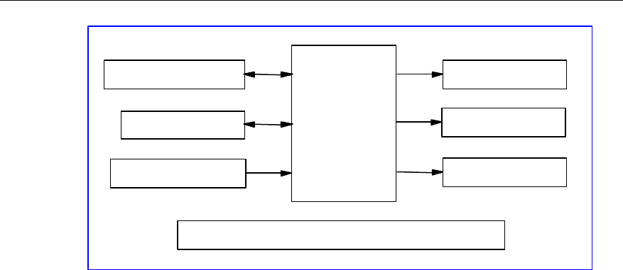
User Manual
Airbridge cBTS3612 CDMA Base Station System Description
2 Hardware Architecture
2-22
Main control unit
Power supply module
Temperature collection module
Communication module
Fan-in-position & fault
detection module
Fan drive module
Switch value alarm module
Indicator drive module
Figure 2-11 Illustration of BFMM
l Power supply module:
System input DC power is +27V, board power consumption is less than 5W.
l Main Control Unit (MCU):
MCU controls the fans and communicates with BCKM. Specifically, it generates
control PWM signal according to the instruction sent from BCKM to control the
speed of fans. MCU can also detect fan alarm signal and in-board logic alarm signal,
and report them to BCKM. It generates panel indicator signal.
l Communication module:
It performs serial communication with BCKM.
l Fan driving module:
PWM control signal generated in MCU provides controlled power input for fans by
isolating driving circuits.
l Fan in position and fault detection module:
This module isolates the fan-in-position signal and fan blocking alarm signal, then
convert them into logic level for MCU to sample and analyze.
l Temperature collection module:
The module collects the ambient temperature information of BFMM in real time,
which is realized by MCU in query operation.
l Indicator driving module:
When functional alarm (such as communication interruption in main control mode)
occurs to the board or fan blocking alarm occurs to the motor, this module provides
LED optical alarm interface inside the fan block, to drive the LED indicator on the
fan block front panel.

User Manual
Airbridge cBTS3612 CDMA Base Station System Description
2 Hardware Architecture
2-23
3) Interface
l Power interface
It is used to lead in working power for BFMM.
l Communication serial port 0, 1
Serial port communication ports 0 and 1 provide access for system active/standby
serial port. When the system has only one serial port, only port 0 is used.
l LED indicator driving output interface
This is the driving interface for LED status indicator on the panel of the fan box.
l Fan unit driving interface
Maximally 6 such interfaces are provided. They also serve as the interfaces for
fan-in-position detection and fan blocked detection.
4) Index
The size of BFMM: 280mm%35mm.
+27V power supply, power consumption <5W.
II. BTS Fan block iNterface Board (BFNB)
1) Overview
BFNB provides electrical connection between the fan box and the system. On one
hand, it provides blind mate interface for the fan box. On the other hand, it provides
the system with power interface and serial communication interface.
2) Structure and principle
BFNB's position is shown in Figure 2-10.
BFNB implements interface conversion function. Refer to "3) Interface" for the
definition of interface.
BFNB's structure is shown in Figure 2-12.
(1) MOLEX connector (2) Large 3PIN power socket (3) DB-15 signal socket
Figure 2-12 Illustration of BFNB structure
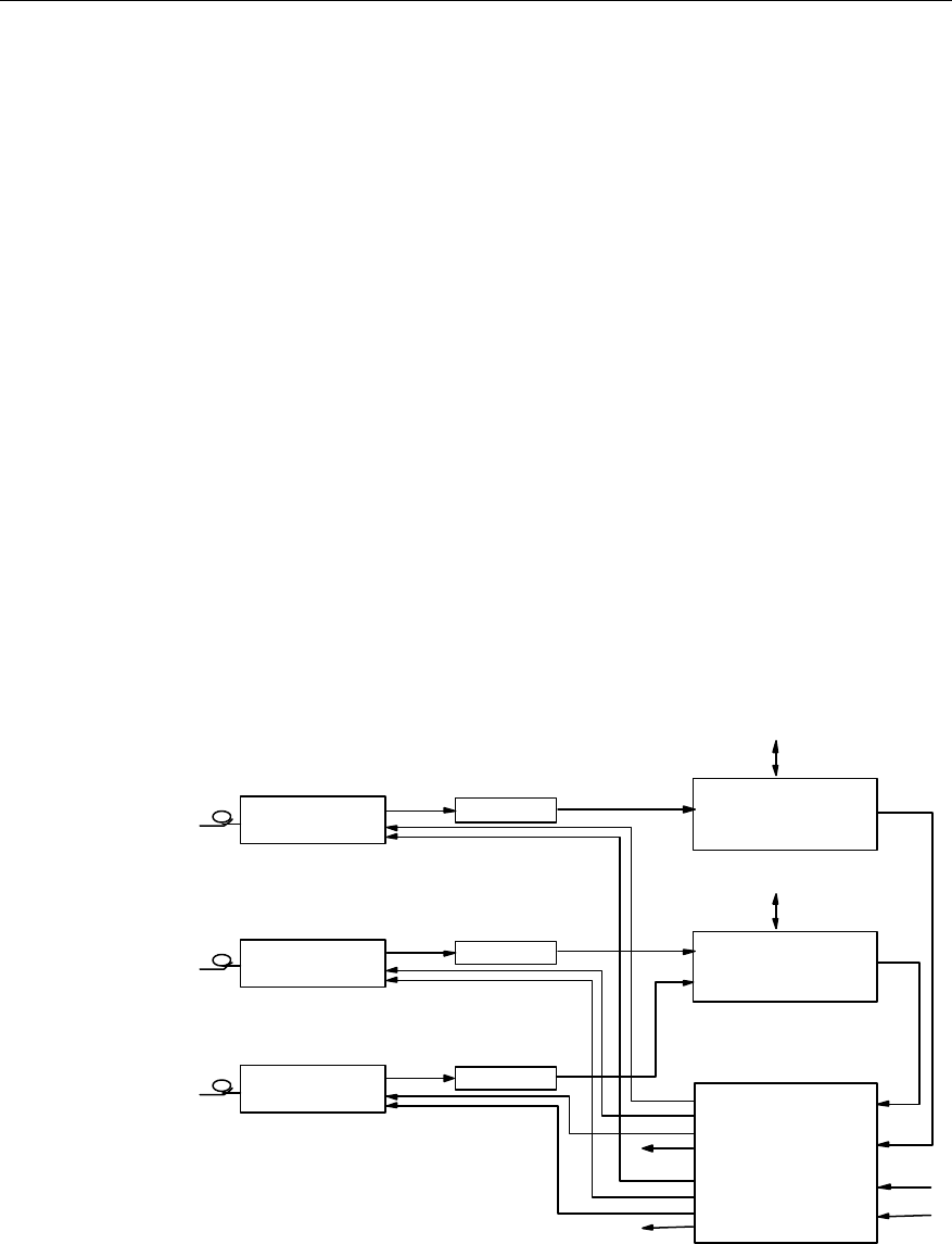
User Manual
Airbridge cBTS3612 CDMA Base Station System Description
2 Hardware Architecture
2-24
3) Interface
l Fan box electrical interface
Power supply ports and serial port communication ports are provided for the two fan
boxes through MOLEX connectors.
l System power supply interface
The interface leads in system power through big 3-pin connector.
l System serial communication interface
External serial communication interface is provided through DB -15.
4) Index
The size of BFNB: 380mm%30mm.
2.3 RF Subsystem
2.3.1 Overview
The structure of RF subsystem is as shown in Figure 2-13.
CDU
RLDU
BHPA
BHPA
BTRM
BTRM
To antenna &
feeder
BRDM
BRDM
BHPA
BTRM
BRDM DFU
f1
f0
f2
To antenna &
feeder
BRDM: Resource Distribution Module BTRM: Transceiver Module BHPA: High Power Amplifier Unit
CDU: Combining Duplexer Unit DFU: Duplexer Filter Unit RLDU: Receive LNA Distribution Unit
Figure 2-13 Structure of RF subsystem
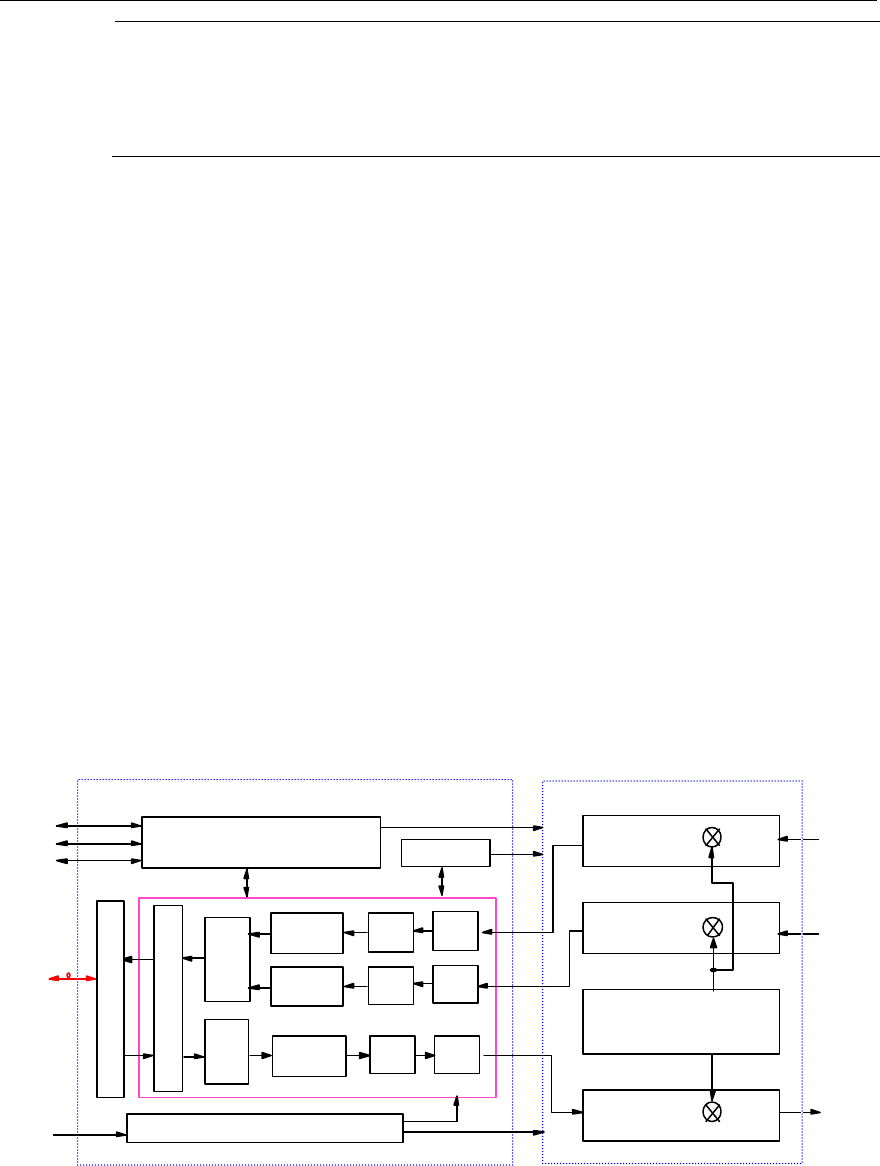
User Manual
Airbridge cBTS3612 CDMA Base Station System Description
2 Hardware Architecture
2-25
&
Note:
The above figure illustrates the RF configuration for 450MHz band. For 800MHz band, the duplexer
would be CDU. For 1900MHz band, the duplexer would be DDU.
In forward link, it performs power adjustable up-conversion and linear power
amplification to the modulated transmission signals, filtering the transmission signals
to meet the corresponding air interface standard.
In reverse link, it filters the signals received by the BTS antenna to suppress
out-band interference, and then performs low-noise amplification, noise factor
adjustable frequency down-conversion, and channel selective filtering.
2.3.2 BTS Transceiver Module (BTRM)
BTRM is in charge of modulating/demodulating of baseband signal, Analog/Digital
and Digital/Analog (AD/DA) conversion, digital up/down conversion and radio
up/down conversion.
I. Structure and principle
BTRM consists of BTS Intermediate Frequency Unit (BIFU) and BTS Radio up-down
Converter Unit (BRCU). Its structure is shown in Figure 2-14.
FIR
&
DAGC
FIR DAC
Demultiplexer/multiplexer
ADC
Power
CPU Clock
Optical interface
Down
converter ADC Filter
BHPA
Local oscillator
BRCU
RLDU
BIFU
RLDU
BTRM
+27V
Main receiver
Diversity receiver
Transmitter
BHPA
PSU
PSU
BHPA
Filter
Filter
Down
converter
Up
converter
Figure 2-14 Structure of BTRM

User Manual
Airbridge cBTS3612 CDMA Base Station System Description
2 Hardware Architecture
2-26
1) BTS Intermediate Frequency Unit (BIFU)
BIFU consists of up-converter, down-converter, multiplexer/demultiplexer, optical
interface, clock, CPU, and power supply sub-unit. It is in charge of the conversion
between the analog intermediate frequency signals and the digital baseband signals,
and the control of the MTRB. The functions of each sub-unit are as below:
l Up-converter
The up-converter accomplishes the wave filtering, digital up-conversion and
digital-analog conversion of the signals in the transmit path.
On receiving the baseband I/Q signals that have been de-multiplexed, it performs
digital up-conversion after baseband filtering. Then the digital intermediate
frequency signals are converted into analog intermediate frequency signals after
digital-analog conversion and wave filtering. At last, the analog intermediate
frequency signals are sent to the transmitter in BRCU via radio frequency (RF)
interface. BRCU.
l Down-converter
The down-converter accomplishes the analog-digital conversion, digital
down-conversion and baseband filtering of the signals in the receive path.
On receiving the analog intermediate frequency signals via the radio interface, it
converts them into digital intermediate frequency signals via analog-digital
conversion. Then the digital intermediate frequency signals are converted into
baseband I/Q signals via digital down-conversion and baseband filtering. As last, the
I/Q signals are transmitted to the demultiplexer/multiplexer.
l Demultiplexer/multiplexer
Under the control of the CPU, the demultiplexer/multiplexer de-multiplexes the
forward I/Q signals, and multiplexes the reverse I/Q signals. At the same time, it
multiplexes/de-multiplexes the operation & maintenance (O&M) signals of the OML.
l Optical interface
The optical interface performs channel coding and decoding, and accomplishes
optical-electrical signal conversion and electrical-optical signal conversion. It is the
interface between the BIFU and the BRDM of the upper-level BTS, and the interface
between the BIFU and the MTRM (Micro-bts Transceiver Module) in the lower-level
SoftSite.
l Clock
The clock generates all the clocks needed by the BIFU, which include the clocks for
up/down conversion, analog-digital conversion (ADC), and digital-analog conversion
(DAC), and other working clocks. At the same time, it also provides the reference
clock for the BRCU.

User Manual
Airbridge cBTS3612 CDMA Base Station System Description
2 Hardware Architecture
2-27
l CPU
The CPU is in charge of the control of BTRM, which includes the initialization upon
power-on, alarm collecting and reporting, and processing operation & maintenance
related messages.
l Power supply
With input voltage of +27V, the power supply sub-unit provides power supply to
BIFU and BRCU.
2) BTS Radio up-down Converter Unit (BRCU)
BRCU consists of transmitter, main/diversity receiver and local oscillator. It
up-converts, amplifies the intermediate frequency signals output by BIFU, and
performs spuriousness-suppression wave filtering. It also performs analog
down-conversion, amplification of BTS main/diversity receiving signal input from the
RLDU, and channel-selection wave filtering. The functions of each sub-unit are as
below.
l Transmitter
When receiving the modulated analog intermediate frequency signals output by
BIFU, the transmitter converts them to specified RF band via two times of
up-conversions. Before and after the up-conversion, wave filtering, signal
amplification and power control are performed, so as to ensure the RF signals
output meet the protocol requirements on power level, Adjacent Channel Power
Radio (ACPR) and spuriousness.
l Main/diversity receiver
It converts the RF signals output by RLDU to specified intermediate frequency
signals via down-conversion, and performs wave filtering, signal amplification and
power control before/after the down-conversion, so as to ensure the intermediate
frequency signals output can be received by BIFU.
l Local oscillator
It consists of the intermediate frequency source and transmit/receive RF synthesizer.
The intermediate frequency source generates the local frequency signals for
intermediate frequency up-conversion in transmit path. The RF synthesizer
generates the local frequency signals for the up-conversion of the transmit path and
the local frequency signals for the down-conversion of main/diversity receive path.
II. Interface
There are interfaces between BTRM and BHPA/RLDU/BRDM/PSU. The
descriptions of each interface are given as below:

User Manual
Airbridge cBTS3612 CDMA Base Station System Description
2 Hardware Architecture
2-28
l BTRM-BHPA RF interface
The RF transmitting signal is output via this interface to BHPA, where the signal is
amplified and then outputted.
l BTRM-BHPA RS485 interface
This interface is used to transfer alarm and control signal, and power detection
signal.
l BTRM-RLDU RF interface
The main/diversity RF receiving signal output by RLDU is received via this interface.
l BTRM-BRDM optical interface
Baseband data are transmitted or received via this interface.
l +27V power supply interface
This interface is used to provide power supply to BTRM.
III. Index
l Supported frequency band: 450MHz band, 800MHz band, 1900MHz band
l Power supply: +27V
l Power consumption: 51W
l Module size: L%W%T=460mm%233.5mm%64mm
2.3.3 BTS High Power Amplifier Module (BHPA)
I. Overview
BHPA is located in RF subrack of BTS cabinet, and used for amplifying the RF
modulation signals output by BTRM. Its main functions are:
l RF power amplification: perform power amplification for the RF modulation
signals from BTRM.
l Over-temperature alarm: when the temperature of power amplifier base board
exceeds a specified threshold, BBFM will process the over-temperature alarm
signal generated by HPAU and report it to BTRM.
l Over-excited alarm: when the power level of BHPA input RF signal exceeds a
specified threshold, BBFM will process the over-excited alarm signal generated
by HPAU and report it to BTRM.
l Gain decrease alarm: when the gain of the power amplifier drops over 6dB,
BBFM will process the gain decrease alarm signal generated by HPAU and
report it to BTRM.
l Fan monitoring: BBFM is installed in BHPA, performing such functions as fan
alarm and power amplifier alarm signal processing & reporting, and fan speed
adjustment.
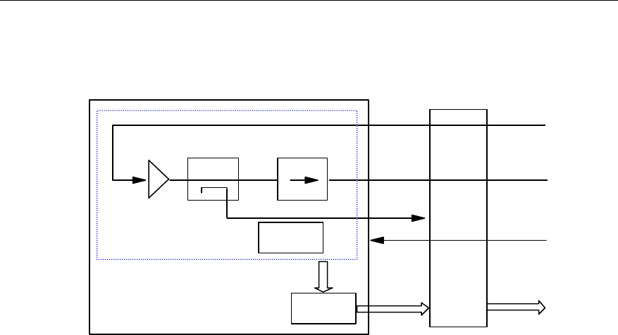
User Manual
Airbridge cBTS3612 CDMA Base Station System Description
2 Hardware Architecture
2-29
II. Structure and principle
The structure of BHPA module includes the following parts, as shown in Figure 2-15:
RF input
Coupler
Power
amplification RF output
BTBM
CDU
BTRM
BBFM
BDCS
Sampling
port
+27VDC
BHPA
Alarm signal
Alarm signal
Alarm
circuit
BTRM
Circulator
HPAUz
Figure 2-15 Block diagram of BHPA module
1) High Power Amplifier Unit (HPAU)
HPAU mainly consists of two parts: power amplifier and alarm circuit. The power
amplifier amplifies the RF signals from BTRM. The amplified RF signals are then
sent to CDU or DFU via BTBM. Alarm circuit monitors the power amplifier status and
generates over-temperature alarm, over-excited alarm and gain decrease alarm
signals when necessary. The alarm signals will be sent to BBFM, where they will be
processed and reported to BTBM. The coupler is used to couple the RF output
signals to the sampling port for test purpose.
The output power of HPAU can be adjusted by controlling the RF output signal of
BTRM.
2) BTS BTRM Fan Monitor (BBFM)
BBFM processes fan alarm signals and power amplifier alarm signals, and sends
them to BTRM via BTBM, and then BTRM will report them to upper level. BBFM can
adjust the fan speed based on the ambient temperature and the actual BHPA output
power in order to lower the noise of fans.
III. Interface
External interfaces of the BHPA module are D-type combination blind mate
connectors, including:

User Manual
Airbridge cBTS3612 CDMA Base Station System Description
2 Hardware Architecture
2-30
l RF interface
The RF interface of BHPA has one input port and one output port. They are
connected respectively with BTRM RF output port via BTBM and CDU/DFU/DDU RF
input port via coaxial cable.
l Power supply interface
Interface with BTS Direct Current Switch box (BDCS).
l Alarm interface
Interface with BTRM. Fan alarm signals and power amplifier alarm signals are sent
via BTBM to BTRM.
IV. Index
l Supported frequency band: 450MHz band, 800MHz band, 1900MHz band
l Max. average output power: ¦ 40W (for 450MHz band and 1900MHz band)
¦ 30W (for 800MHz band)
l Power supply: +27V
l Power consumption: <380W
l Module size: L%W%T=460mm%233.5mm%64mm
2.3.4 BTS Transceiver Backplane Module (BTBM)
BTBM interconnects six BTRMs and six BHPAs. It provides six sets of 2mm
connectors for BTRM, six sets of 24W7 combination D-type blind mate connectors
for BHPA, and three DB9 connectors for RLDU alarm collection, and six sets of
temperature sensors.
The above parts form three independent function groups, as shown in Figure 2-18.
l BTRM 2mm connector
Each set of 2mm connectors includes one 5%22pin A-connector and three 3-socket-
N-connectors. A-connector transfers RLDU alarm signals from DB9 connector and
RS485 interface message from BHPA 24W7 combination D-connector. N-connector
transfers the main/diversity input/output RF signal of BTRM and +27V DC power
signal needed by BTRM.
l BHPA 24W7 D-type combination blind mate connector
Each 24W7 D-type combination blind mate connector includes 2 coaxial contacts
(transferring BHPA input/output RF signals), 2 high-current power contacts
(transferring +27V power supply and PGND signals), one set of RS485 signal
contacts and a group of contacts for temperature sensor signals.
l DB9 connector
There are 3 angled DB9 connectors on BTBM for 3 RLDUs alarm signals transferred
to BTRM.
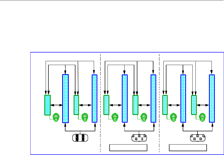
User Manual
Airbridge cBTS3612 CDMA Base Station System Description
2 Hardware Architecture
2-31
l Temperature sensor
There are 6 temperature sensors for the 6 BHPA slots, used for sensing the air
temperature at each BHPA air outlet. They will convert the information into current
and send to BFMM on BHPA for processing. In this way, fan speed is controlled in
real time.
DB9 connector
RLDU alarm signal
24W7DB
connector
Temperature sensor Temperature sensor
2mmA /N
connector
RS485
RS485
RS485 RS485
Functional group 1Functional group 3Functional group 2
Figure 2-16 Functional blocks of BTBM
l Index
Board size: L%W%T= 664mm%262mm%3mm
2.3.5 Combining Duplexer Unit (CDU)
I. Overview
CDU mainly has the following functions:
l Combine two carrier signals from the two BHPAs into one signal.
l Isolation and filtering of receiving and transmitting signals.
l Filtering of transmitting signals so as to suppress BTS spurious emissions.
l Filtering of receiving signals so as to suppress the interference from outside the
receive band.
Key internal parts of CDU include isolator, 2-in-1 combiner, duplexer, and directional
coupler.
II. Structure and principle
CDU structure is as shown in Figure 2-17.
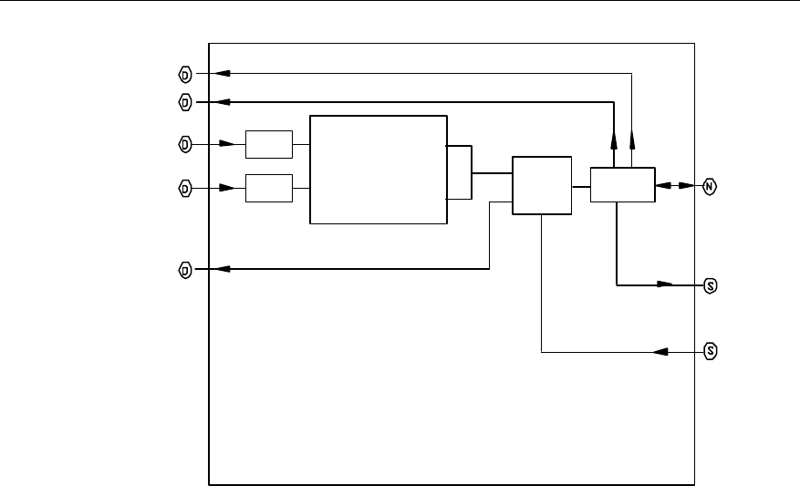
User Manual
Airbridge cBTS3612 CDMA Base Station System Description
2 Hardware Architecture
2-32
Pr-OUT
Pf-OUT
TX1
TX2
RXM-OUT
Combiner
Duplexer Directional
coupler
RXM-Test
TX-Test
TX/RXM-ANT
Isolator
Isolator
Figure 2-17 Structure of CDU
l Isolator
There are two isolators at each input port of the combiner in CDU. They are used to
isolate the two carriers from two input ports.
l 2-in-1 combiner
The combiner is a narrow band cavity filtering combiner. In comparison with
broadband combiner, it features lower insertion loss and effective isolation.
l Duplexer
The duplexer is used to isolate transmitted signals and received signals, suppress
transmission spurious and reduce antenna quantity.
l Directional coupler
The directional coupler couples forward/reverse power to RLDU, and monitors the
antenna VSWR.
III. Interface
CDU is a module shared by transmit and receive path of the BTS. It has interfaces
with other modules both in the transmitting and receiving paths. Its external
interfaces include a set of 8W8 D-type combination blind mate connectors on the
backside, and a set of N-connectors and SMA connectors on the front side. The
interface signals include:

User Manual
Airbridge cBTS3612 CDMA Base Station System Description
2 Hardware Architecture
2-33
l RF signals between CDU combiner input ports and BHPA output ports. They
are transferred through the blind mate connectors on the backside.
l BTS transmitting signals, which are transferred to the cabinet-top antenna
interface through the RF cable connected with the N-connector at the front side
of CDU.
l BTS receiving signals, which are transferred from the cabinet-top antenna
interface through the RF cable connected with the N-connector on the front side
of CDU.
l BTS receiving signals output from the duplexer. They are sent to RLDU via the
blind mate connector on the backside.
l Forward/reverse coupled RF signals, which are sent to RLDU via the blind
mate connector on the backside.
l Forward/reverse coupled test signals, which are outputted through the standard
SMA connector on the front side of CDU.
IV. Index
l Number of combined channels: 2
l Supported frequency band: 450MHz band, 800MHz band
l Module size: L%W%H=450mm%100mm%344.8mm
2.3.6 Duplexer Filter Unit (DFU)
I. Overview
DFU mainly fulfills the following functions:
l Isolation and filtering of transmitting and receiving signals for the single carrier.
l Filtering of diversity receiving signals in order to suppress out-band
interference.
Key parts of DFU includes low-pass filter, duplexer, diversity receive filter and
directional coupler.
II. Structure and principle
DFU structure is shown in Figure 2-18.
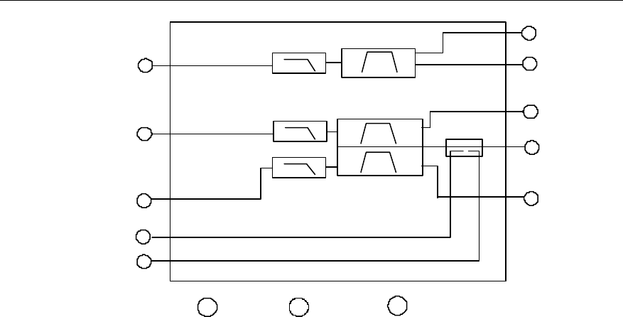
User Manual
Airbridge cBTS3612 CDMA Base Station System Description
2 Hardware Architecture
2-34
N
D-SUB S
D
N-Type SMA-Type
N
S
S
D
D
D
D
TX-TEST
TX/RXM-ANT
RXM-TEST
Pf-OUT
Pr-OUT
TX
RXM-OUT
Low-pass filter
D
RXD-OUT NRXD-ANT
SRXD-TEST
Diversity receive filter
Low-pass filter Duplexer
Directional coupler
Figure 2-18 Structure of DFU
l Low-pass filter
At the transmitting signal input port and main/diversity receiving signal output port,
there are three low-pass filters used for low-pass filtering of transmitting and
main/diversity receiving signals.
l Duplexer
The duplexer is used to isolate transmitting and receiving signals, suppress
transmission spurious and reduce antenna quantity.
l Diversity receive filter
The diversity receive filter of DFU is a separate path. Signals received by the
diversity antenna must be filtered by the diversity receive filter in DFU before being
sent to the low-noise amplifier in RLDU for amplification.
l Directional coupler
The directional coupler couples forward/reverse power for RLDU, and monitors the
antenna VSWR.
III. Interface
DFU is a module shared by transmit and receive path of the BTS. It has interfaces
with other modules in the transmit and receive paths. Its external interfaces include
a set of 8W8 D-type combination blind mate connectors on the backside, and a set
of N connectors and SMA connectors on the front side. The interface signals
include:
l The signals between DFU and BHPA, which are transferred through the blind
mate connectors on the backside.

User Manual
Airbridge cBTS3612 CDMA Base Station System Description
2 Hardware Architecture
2-35
l BTS transmitting signals, which are transferred to the cabinet-top antenna
interface through the RF cable connected with the N-connector at the front side
of the module.
l BTS receiving signals, which are transferred from the cabinet-top antenna
interface to DFU for filtering through the RF cable connected with the
N-connector on the front side of the module.
l BTS receiving signals output from the duplexer and diversity receive filter. They
are sent to RLDU via the blind mate connector on the backside.
l Forward/reverse coupled RF signals, which are sent to RLDU via the blind
mate connectors on the backside.
l Forward/reverse coupled test signals, which are outputted through the standard
SMA connector on the front side.
IV. Index
l Supported frequency band: 450MHz band
l Module size: L%W%H=450mm%100mm%344.8mm
2.3.7 Dual Duplexer Unit (DDU)
I. Overview
DDU completes the following functions:
l Isolation and low-pass filtering of two receiving and transmitting signals.
l Providing two DC feeds to T-type tower-top amplifier.
l Voltage Standing Wave Ratio (VSWR) test on transmit channels in both
forward and backward directions.
l Coupling test of transmitting and receiving signals.
Key components within DDU include Bias-T DC feed connector, low-pass filter,
duplexer, and bi-directional coupler.
II. Structure and principle
DDU structure is shown in Figure 2-19.
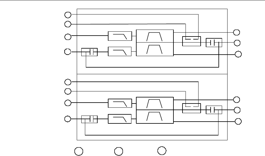
User Manual
Airbridge cBTS3612 CDMA Base Station System Description
2 Hardware Architecture
2-36
ND-SUB S
DN-Type SMA-Type
LPF
DUPLEXER
COUPLER N
S
S
D
D
D
D
TX2-TEST
TX/RXD-ANT
RXD-TEST
Pf2-OUT
Pr2-OUT
TX2
RXD-OUT
LPF
LPF
DUPLEXER
COUPLER N
S
S
D
D
D
D
TX1-TEST
TX/RXM-ANT
RXM-TEST
Pf1-OUT
Pr1-OUT
TX1
RXM-OUT
LPF
BIAS T
BIAS T
BIAS T
BIAS T
Figure 2-19 Structure of DDU
l Low-pass filter
The low-pass filter is used to suppress the high-order harmonic wave. The low-pass
filter on receive channel also functions to suppress the interference from the
transmit channel.
l Duplexer
The duplexer is used to isolate transmitting signals and receiving signals, suppress
transmission spurious and reduce antenna quantity.
l Bi-directional coupler
The bi-directional coupler couples forward/reverse power for RLDU, and monitors
the antenna VSWR.
l T-type feed connector
This connector receives the RF signals and divides/combines DC feeds, so that the
RF signals and DC go through different channels, realizing the DC supply to the
tower-top amplifier.
III. Interface
DDU is a module shared by the transmitting and receiving paths of the BTS. It has
interfaces with other modules both in the transmitting and receiving paths. Its
external interfaces include a set of 8W8 DB combination blind mate connectors on
the backside, and a set of N-connectors and SMA connectors on the front. The
interface signals include:

User Manual
Airbridge cBTS3612 CDMA Base Station System Description
2 Hardware Architecture
2-37
l Signals between transmit input port and BHPA port. They are transferred
through the blind mate connectors on the back side.
l Transmitting signals, which are transferred to the cabinet-top antenna port
through the RF cable connected with the N-connector at the front side of DDU.
l Receiving input signals, which are transferred from the cabinet-top antenna port
through the RF cable connected with the N-connector on the front side of DDU.
l Signals output from the receive filter. They are sent to RLDU via the blind mate
connector on the back side.
l Transmitting forward/reverse coupled RF signals, which are sent to RLDU via
the blind mate connector on the back side.
l Transmitting and receiving coupled test signals, which are outputted through
the standard SMA connector on the front side of DDU.
IV. Index
l Supported frequency band: 1900MHz band
Module size: L%W%T=450mm%100mm%344.8mm
2.3.8 Receive LNA Distribution Unit (RLDU)
I. Overview
RLDU consists of Low Noise Amplifier), distribution unit, configuration switch and
alarm monitoring circuit. Its main functions are:
l Low noise amplification and distribution for BTS receiving signals.
l Built-in electronic RF switch supports multiple BTS configurations (3 sectors or
6 sectors).
l Antenna VSWR monitoring and alarming, BTS forward RF power detecting,
LNA running status monitoring and alarming.
II. Structure and principle
RLDU structure is shown in Figure 2-20.
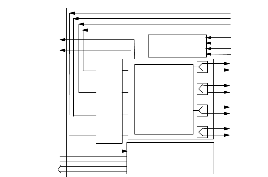
User Manual
Airbridge cBTS3612 CDMA Base Station System Description
2 Hardware Architecture
2-38
VSWR check processing
VSWR and power
check
LNA
module
Switch distribution
module
DC-IN
PWR
S/W
DB15
RXAM-TEST
RXBM-TEST
RXBD-IN
RXBM-IN
RXAD-IN
RXAM-IN
APf-IN
APr-IN
BPf-IN
BPr-IN
RXAM1
RXAM2
RXAD1
RXAD2
RXAM3/RXBM1
RXAM4/RXBM2
RXAD3/RXBD1
RXAD4/RXBD2
Power supply
Forward power output
Figure 2-20 Structure of RLDU
1) Receiving signal low noise amplification and distribution unit
There are 4 LNAs and distributors inside RLDU, which can process 4 signals. The 4
LNAs have the same specifications such as gain, noise factor and dynamic, so the 4
receive paths are balanced.
2) Configuration switch unit
The electronic switches inside RLDU are designed for supporting different BTS
configurations. When the BTS is configured in 3-sector mode, the electronic
switches can be set to make RLDU operate in a single-sector mode that has two
main/diversity receiving paths (Each path provides 1-in-4 output to support 1~4
carriers configuration for each sector). When the BTS is configured in 6-sector mode,
the electronic switches can be set to make RLDU operate in two-sector mode each
of which having 4 main/diversity receive paths (Each path provides 1-in-2 output,
supporting 1~2 carriers configuration for each sector).
3) Antenna VSWR and LNA status monitoring unit
The transmitted forward/reverse power coupling signals from CDU or DFU or DDU
are processed in the antenna VSWR monitoring circuit inside RLDU. When the
VSWR of transmitting antenna exceeds a specified threshold, alarm will occur. At
the same time, RLDU also converts transmit coupling power signal into DC level
signal through its RF power detecting circuits. Through this DC level signal, any

User Manual
Airbridge cBTS3612 CDMA Base Station System Description
2 Hardware Architecture
2-39
exception of transmit signal power of antenna can be monitored in real time. LNA
status monitoring circuit monitors the voltage and current of the 4 LNAs inside
RLDU. It gives alarm when fault t is found.
III. Interface
RLDU is the reverse link function module of the BTS, which interfaces with
CDU/DFU and BTRM in both input side and output side through the two sets of 8W8
D-type combination blind mate connectors on the backside of the module.
1) Interface signals between RLDU and CDU/DFU/DDU are:
l Main/diversity path receiving RF signals outputted from two CDU/DFU/DDU
receive filters. They are amplified and distributed by RLDU.
l CDU/DFU/DDU coupling RF signal, which are used for antenna VSWR
monitoring and forward power detecting.
2) Interface signals between RLDU and BTRM are:
l Main/diversity path receiving RF signals transmitted to BTRM after being
amplified and distributed.
l Antenna VSWR, LNA status monitoring alarm signals and forward power
detecting voltage signals, which are outputted to BRCU by RLDU through a
DB15 interface on the front side of the module and transferred to BIFU for
processing.
3) The +27V DC power is necessary for RLDU. It is provided directly by the
secondary power supply module in the BTS through a MOLEX power connector on
the front side of the module.
IV. Index
l Supported frequency band: 450MHz band, 800MHz band, 1900MHz band
l Power supply: +27VDC
l Power consumption <50W
l Module size: L%W%H= 450mm%180mm%50mm
2.3.9 BTS RF Fan Module (BRFM)
BRFM mainly consists of BBFM, BBFL and fans. The following is the introduction to
BBFM and BBFL.
I. BTS BTRM FAN Monitor (BBFM)
1) Overview
BBFM collects and analyzes the temperature information of BHPA module and
adjust the fan speed in real time to lower the system noise, so as to prolong
User Manual
Airbridge cBTS3612 CDMA Base Station System Description
2 Hardware Architecture
2-40
equipment service life and improve the external performance of the overall system
on the premise that the system works in a safe thermal status. The Pulse Wide
Modulation (PWM) control signal regarding the fan speed can be generated by the
MCU of the local board or configured by the control unit of BTRM module. At the
same time, BBFM reports to BCKM the gain decrease, over-temperature,
over-excited alarm and fan failure alarm of BHPA, to ensure the reliability of BHPA
module. Specifically, it functions to:
l Control fan speed, monitor and report fan alarm.
l Monitor and report BHPA alarm.
l Drive fan monitor indicator module.
l Collect temperature information of BHPA module.
l Communicate with BTRM module.
2) Structure and principle
The position of BBFM in BHPA module is as shown in Figure 2-21.
Fan cover
BHPA
BBFM
Blind mate
connector
Figure 2-21 Position of BBFM in BHPA module
The structure of BBFM is shown in Figure 2-22.
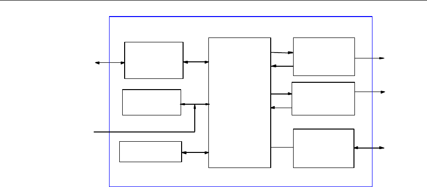
User Manual
Airbridge cBTS3612 CDMA Base Station System Description
2 Hardware Architecture
2-41
MCU
Communication
interface
Watchdog
HPAU
Interface
circuit
PWM
Modulation
circuit
Panel indicator
driving alarm
signal isolation
circuit
Temperature
collection
Serial port
BBFM
BHPA
External
temperature
collection
Fan cover
BTRM
Figure 2-22 Structure of BBFM module
l MCU module
The MCU module collects and analyzes the temperature information to generate
PWM signal for controlling the fan speed, receives alarm signals generated by
BHPA module and fan alarm signals and reports to BTRM module, generates panel
indicator signal and communicates with BTRM module.
l BHPA interface module
This moduloe isolates and drives the interface with BHPA.
l Temperature information collection module
This module collects the temperature information of BHPA module in real time,
which is implemented by MCU in query operation.
l Panel indicator driving and alarm signal isolation module
It is used to drive the panel indicator and isolate fan alarm signals.
l Communication module
The module performs serial communication with BTRM module.
l Power supply module
The input power of BFMM is +27V, power consumption is 3.5W (including power for
the fans).
3) Interface
l BHPA interface
Interface with BHPA module, used for BHPA alarm monitoring.
l Serial communication interface
Interface used to report the alarm of the fans and BHPA module.
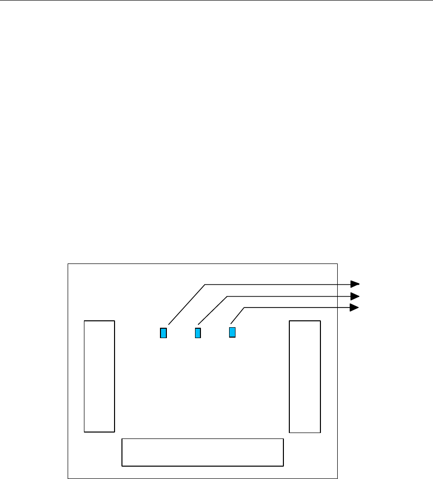
User Manual
Airbridge cBTS3612 CDMA Base Station System Description
2 Hardware Architecture
2-42
l Interface with the fan cover
Including fan alarm signal, panel indicator, and fan power interface.
4) Index
Size of BBFM: 200.0mm%55.0mm.
II. BTS BTRM FAN Lamp Module (BBFL)
1) Overview
BBFL has three RUN indicators to indicate the running status of BTRM module, fans
and BHPA module. The board is connected with BBFM via the fan cover interface. It
is an auxiliary board.
2) Structure and principle
The structure of BBFL is shown in Figure 2-23.
Fan cover port (connect to BBFM)
BHPA indicator
FAN indicator
BTRM indicator
LED1 LED2 LED3
Fan 2 interface
Fan 1 interface
Figure 2-23 Structure of BBFL module
BBFL consists of the following parts:
l Fan 1 interface module
It is a 4pin ordinary socket connector connected with Fan 1, including power supply
input port and fan alarm output port.
l Fan 2 interface module
It is a 4pin ordinary socket connector connected with Fan 2, including power supply
input port and fan alarm output port,

User Manual
Airbridge cBTS3612 CDMA Base Station System Description
2 Hardware Architecture
2-43
l Fan cover port interface module
It is connected with the fan cover of BBFM.
3) Panel indicator
LED1: BTRM operating signal
LED2: Fan operating signal
LED3: BHPA operating signal
4) Index
Size of BBFL: 55.0mm%25.0mm.
2.4 Antenna & Feeder Subsystem
2.4.1 Overview
BTS antenna & feeder subsystem consists of two parts: RF antenna & feeder, and
dual-satellite synchronization antenna & feeder. The former transmits the modulated
RF signals and receives MS signals, while the latter provides precise
synchronization for CDMA system.
2.4.2 RF Antenna & Feeder
RF antenna & feeder of the BTS is composed of outdoor antenna, jumper from
antenna to feeder, feeder, and the jumper from feeder to cabinet-top, as shown in
Figure 2-24.
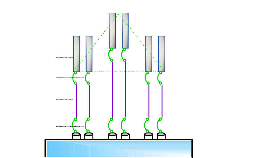
User Manual
Airbridge cBTS3612 CDMA Base Station System Description
2 Hardware Architecture
2-44
Sector
α
Sector
βSector
γ
Antenna
Feeder
Jumper
Jumper
BTS cabinet
Figure 2-24 Structure of RF antenna & feeder
I. Antenna
Antenna is the end point of transmitting and start point of receiving. Type, gain,
coverage pattern and front-to-rear ratio of the antenna can affect the system
performance. The network designer should choose antenna properly based on the
subscriber number and system coverage.
1) Antenna gain
Antenna gain is the capability of the antenna to radiate the input power in specific
directions. Normally, the higher gain, the larger coverage. But there may be blind
area in the vicinity.
2) Antenna pattern
Antenna pattern describes the radiation intensity of the antenna in all directions. In
the field of telecommunication, it usually means a horizontal pattern. BTS antenna is
available in two types: 360â omni antenna and directional antenna. The directional
antenna includes the following types: 120â , 90â , 65â and 33â .
3) Polarization
Polarization is used to describe the direction of the electrical field. The mobile
communication system often uses uni-polarization antennas. Bi-polarization
antennae have been used recently to reduce the quantity of antennae. The two
polarization directions are perpendicular to each other.

User Manual
Airbridge cBTS3612 CDMA Base Station System Description
2 Hardware Architecture
2-45
Normally Bi-polarization directional antenna is used in directional cell. Comparing
with the uni-polarization directional antenna, the bi-polarization directional antenna
is cost-effective, space saving and easy to install. However, uni-polarization omni
antenna is still adopted in omni cell.
4) Diversity technology
Electrical wave propagation in urban area has the following features:
l Field intensity value changes slowly with places and times. It changes in the
rule of logarithmic normal distribution, which is called slow attenuation.
l Field intensity transient value attenuates selectively since it is multi-path
transmission. The attenuation rules falls in Rayleigh distribution, which is called
fast attenuation.
Either fast attenuation or slow attenuation impairs the quality of communication or
even interrupts the conversation. Diversity technology is one of the most effective
technologies to tackle the attenuation problem. Diversity receiving and combining
technology can be used to minimize the attenuation when there is little correlation
between the two attenuated signals. There are polarized diversity and space
diversity. In the present mobile communication system, horizontal space diversity
and polarized diversity are both supported. Theoretical conclusion shows that space
diversity is effective when the distance between two antennae is over 10
wavelengths. Polarized diversity facilitates antenna installation and saves space,
therefore it is used more and more extensively.
5) Antenna isolation
The receiving/transmitting antenna must be installed with sufficient isolation to
minimize the effect on the receiver. The isolation space is subject to the out-band
noise of the transmitter and the sensitivity of the receiver. Please refer to cBTS3612
Installation Manual for details.
II. Feeder
Normally, the standard 7/8 inch or 5/4 inch feeders are used to connect the outdoor
antenna and indoor cabinet. In the site installation, 7/16 DIN connectors are needed
based on the actual length of feeders. Three grounding cable clips for lightning
protection should be applied at the tower top (or building roof), feeder middle, and
the wall hole where feeder enter indoors. If the feeder is excessively long, additional
cable clips are needed.
Since 7/8 inch feeder should not be bent, the tower top (or building roof) antenna
and the feeder, indoor cabinet and the feeder should be connected via jumpers. The
specifications of Huawei standard jumpers are 1/2 inch, 3.5m long, with 7/16DIN
connectors.

User Manual
Airbridge cBTS3612 CDMA Base Station System Description
2 Hardware Architecture
2-46
III. Lightning arrester (Optional)
When the cBTS3612 is configured for 1900MHz band, the lightning arrester is
necessary, but for the other bands, it is not necessary.
The lightning arrester is used to prevent damage of lightning current to the antenna
and feeder system. Usually, there are two kinds of lightning arresters. The first type
uses the microwave principle to conduct the low frequency lightning current to the
ground so as to sink the current. The second one is a discharging tube, when the
voltages at both ends of the discharging tube reach a certain value, the tube
conducts to sink the large current. The second technique is used in cBTS3612.
Lightning arrester should be installed close to the BTS cabinet, for details, please
refer to cBTS3612 Installation Manual.
IV. Tower-top Amplifier (Optional)
When the cBTS3612 is configured for 1900MHz band, the tower-top amplifier is
optional, for the other bands, it is not necessary.
Tower-top amplifier is used to further improve the signal quality. Normally it is
installed close to the antennas, consisting of triplex filter and low noise amplifier.
The triplex filter is actually a device composed of two duplex filters.
Signals from the antennas first pass through the triplex filter to filter out the out-band
interference, then the low noise amplifier amplifies the weak signals. Finally the
amplified signals are sent over the low loss cable to the BTS.
The purpose of the tower top amplifier is to enhance the receiving sensitivity of the
base station. So the tower-top amplifier is required to have a low noise coefficient.
The power of the signals received on the antenna varies greatly with the distance
between the MS and the base station. This requires that the tower- top amplifier
have a greater dynamic range.
Besides, the tower-top amplifier also has the by-pass function in case of DC power
failure.
The DC power supply of tower-top amplifier is fed through the center conductor of
the receiving feeder by DDU. Since it is an outdoor device, so a reliable waterproof
sealing is required.
The tower-top amplifier can operate under -40oC~60oC.

User Manual
Airbridge cBTS3612 CDMA Base Station System Description
2 Hardware Architecture
2-47
2.4.3 Dual-Satellite Synchronization Antenna & Feeder
I. Overview
Many important features of CDMA system are closely related with global satellite
navigation system and are much dependent on it. If global satellite navigation
system does not work for a long time, the whole network will collapse. In
consideration of the system security and reliability, BTS receives the signals of GPS
system or of GLONASS system through the dual-satellite synchronization antenna &
feeder, to implement radio synchronization. In this way, the whole network can
operate normally without any adverse effect when GPS or GLONASS system is not
available. The following describes the application of GPS and GLONASS in CDMA
system.
1) GPS
CDMA network can be synchronized with GPS. GPS is a high precision global
positioning system set up by American Navy Observatory. It is a all-weather satellite
navigation system based on high frequency radio. It provides 3D-position
information, so users can attain high precision information about position, speed and
time. The 3D-position is accurate to less than 10 yard (approx. 9.1m) in space and
less than 100ns in time. The received signal is processed and used as the master
reference frequency.
The whole system consists of three parts: space part, land control part and user
part.
Space part is a group of satellites 20,183 kilometers high, orbiting the earth at a
speed of 12 hours/circle. There are 24 satellites together, running on 6 orbits. The plane of
each orbit is at a 55â angle with the equator.
The land control part consists of a main control center and some widely distributed
stations. The land control network tracks the satellites and controls their orbits
accurately. It also corrects astronomical data and other system data from time to
time and transmits to users through the satellites.
The user part includes the GPS receivers and their supporting equipment. The
CDMA system is actually a GPS user utilizing the timing function of GPS. GPS
satellites are synchronized with a cesium atom clock group on the land. Therefore,
GPS timing signal is steady and reliable. The frequency is in a long-term stability of
cesium atom clock level. BTS provides a highly stable crystal clock, which is stable
on a short-term base. The crystal clock together with GPS signals ensures the clock
absolute stability and reliability of CDMA system.

User Manual
Airbridge cBTS3612 CDMA Base Station System Description
2 Hardware Architecture
2-48
2) GLONASS
GLONASS is a global satellite navigation system developed by the former Soviet
Union and inherited by Russia. It is of a similar structure to GPS. There are 24
satellites distributed on 3 orbits. The inclination of the orbit is 64.8â and the height is
18840~19940 km. The satellites go around the earth one circle every 11 hours 15
minutes and 44 seconds. Satellites are identified with frequency division
multi-address, i.e. different satellites use different frequencies. Since the inclination
of the orbits is greater than that of GPS, the visibility at high latitude area (over 50â )
is better than that of GPS. The design service life of the present satellites is 3~4
years. The service life of the new generation GLONASS will be 5 years, with
enhanced functions of inter-satellite data communication and autonomous running.
At present, only 19 satellites are working in the constellation and some of them are
not working well. The coverage is not as large as GPS system.
The user equipment receives C/A code, P code and two carrier signals modulated
from the navigation data L1: 1602MHz +<fL1, L2: 1 246 MHz+<fL2 (<fL1, <fL2 are
frequency increments of different satellites), to identify the position of the satellite
and measure the distance between the user and the satellite. In this way, the
position of the user can be figured out. The algorithm used is similar to that of GPS.
Huawei BTS system uses intelligent software phase-locking and holdover
technology to minimize the interference such as signal wander and jitter due to
ionosphere error and troposphere error of GPS satellites. BTS system can not only
provide accurate timing signal, but also provide accurate calendar clock (hour,
minute, second). Huawei BTS supports GPS/GLONASS dual-satellite system
synchronization mode, providing two synchronization solutions (GPS or
GPS/GLONASS) as required by the user.
II. Antenna
l GPS antenna
The antenna is an active antenna. The L1 band GPS signals received by GPS
antenna are filtered by a narrow-band filter and amplified by a preamplifier. Then
they are sent to a GPS receive card. GPS antenna supports all kinds of GPS
receivers. Performance indices are as follows:
Frequency: 1.575GHz
Bandwidth: 20MHz
Voltage: +5.0 ! 0.25VDC
Current: 35mA
Impedance: 50Ù

User Manual
Airbridge cBTS3612 CDMA Base Station System Description
2 Hardware Architecture
2-49
Polarity: RHCP
l GPS/GLONASS dual-satellite receiving antenna
This antenna receives L1 GPS signals (1.575GHz) and GLONASS signals
(1.611GHz). The power voltage is 5~18V.
III. Feeder
The feeder is the physically foamed polyethylene insulation RF coaxial cable, with
the impedance of 50-ohm and specification of 10-FB. Nominal indices are:
70dB/km (400MHz)
113dB/km (900MHz)
The loss at 1.575GHz frequency is 13.78dB every 100m.
The coaxial cable is mainly used to transmit the GPS signals received by the GSP
antenna to GPS card. At the same time, the coaxial cable also provides power for
the antenna module to make pre-amplification.
This kind of cable is used when dual-satellite solution is adopted.
IV. Lightning arrester of antenna and feeder
The lightning arrester of antenna and feeder used in BTS features clamp voltage of
-1~+7VDC, standing wave ratio of less than 1.1:1, and signal attenuation of less
than 0.1dB (1.2~2GHz).
V. Receiver
GPS receiver has 8 parallel paths, capable of tracking 8 satellites concurrently. The
receiver receives GPS signal of band L1 (1575.42MHz) and tracks C/A code. The
receiver must be powered with regulated 5V DC. Inside the receiver, the RF signal
processor makes frequency down-conversion to the GPS signal received by the
antenna to get Intermediate Frequency (IF) signal. The IF signal is then converted to
digital signal and sent to 8-path code and carrier correlator, where signal detection,
code correlation, carrier tracking and filtering are performed. The processed signal
is synchronized and sent to positioning MPU. This part of circuit controls the
operational mode and decoding of GPS receiver, processes satellite data, measures
pseudo-distance and pseudo-distance increment so as to figure out the position,
speed and time. The sensitivity of the receive card is -137dBm.
The dual-satellite receive card has 20 receiving paths. GPS L1 can be upgraded to
GPS/GLONASS L1+L2 or other solutions. The timing accuracy of the card is up to
25ns.

User Manual
Airbridge cBTS3612 CDMA Base Station System Description
2 Hardware Architecture
2-50
2.5 Power Supply Subsystem
2.5.1 Overview
BTS built-in power supply module converts -48V DC into +27V for the BTS, forming
the power supply subsystem together with power distribution, lightning protection
and power monitoring.
According to the requirement of BTS overall design, each site can be configured
with multiple cabinets as required. Different cabinets are interconnected so that
different network configurations can be implemented with flexibility, convenience and
reliability. Therefore the power supply subsystem also needs flexible, convenient
and reliable distribution monitoring solution such as centralized lightning protection,
distributed DC power (i.e. the power supply subsystem of each cabinet is an
integrated system and each power supply module has its own built-in monitoring
unit). These units are connected on the backplane, and information is report to
BTRM through the universal monitoring bus to implement power management and
monitoring.
The -48V power input is filtered by EMI filter and connected to the wiring terminal on
the cabinet top, and then connected to the power backplane input bus bar in the
secondary power supply subrack. The +27V power is output to the output bus bar of
power subrack backplane, then led out from the bus bar, the power cable goes up
along the wiring trough to the distribution copper bar in the DC switchbox on top of
the cabinet. The distribution copper bars in the switchbox distribute +27V DC power
to different modules (the power passes the over-current protection devices for each
power consumption unit and is connected to the output terminals at the back of the
distribution box). In this way, it is ensured that when the power supply to a unit fails
due to over-current, other units will not be affected.
The structure of the whole power supply subsystem is shown in Figure 2-25.
Lightning protection
power distribution
DC/DC
module
DC/DC
module
DC/DC
module
EMI
filter
-48V
+27VDC OUT
Load
.....
Monitoring
serial port
Figure 2-25 BTS power supply subsystem
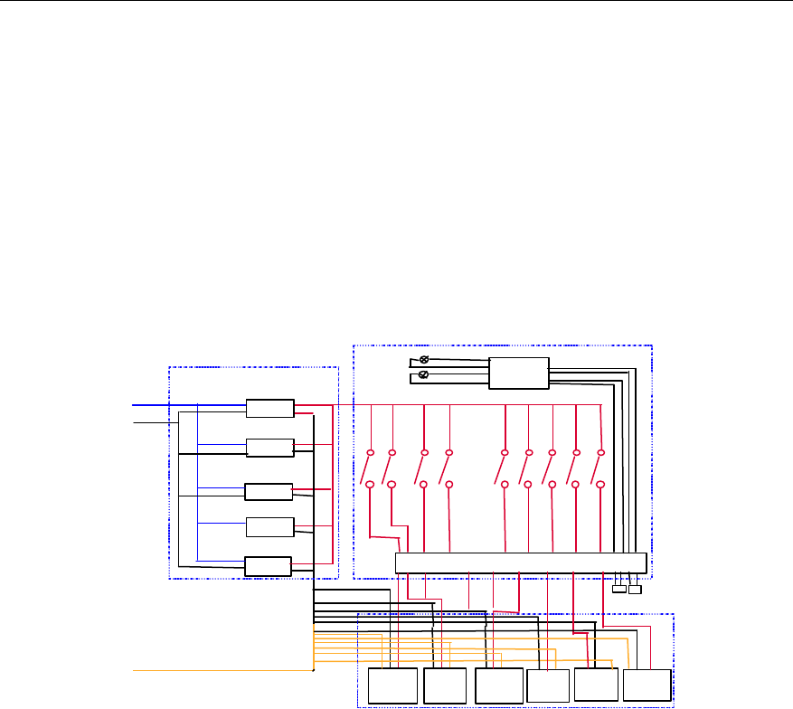
User Manual
Airbridge cBTS3612 CDMA Base Station System Description
2 Hardware Architecture
2-51
2.5.2 General Structure
The -48V power is filtered by the EMI filter on top of the cabinet, and then goes
down along the wiring trough, and finally connected to the input bus bar of the
power subrack backplane. The power supply subsystem uses five +27V/65A DC/DC
power supply units (PSU) in full configuration. These five PSUs operation in 4+1
redundancy to ensure an output of at least 7200W. The size of PSU is L%W%H =
400mm%121.9mm%177.8mm.
The overall structure of the power supply system is shown in Figure 2-26.
Wiring terminals
-48VIN
GND
DC/DC
DC/DC
DC/DC
Power supply subrack
Switch box
-48V power supply indication
From cabinet-top LGND
DU …
TRX0
PGND
RLDU1TRX11
16 service units RLDU0 RLDU2
Indicator PCB
DC/DC
DC/DC
...
...
Figure 2-26 Structure of power supply system
2.5.3 Technical Indices
I. DC input lightning protection
DC input lightning protection part is an external cabinet-top lightning arrester. It
mainly features:
l Temperature-controlled fusing technology and built-in over-current protection
circuit to prevent fire.
l Multiple autonomous current equalization technology used to withstand
successive lightning attack.
l Common mode and differential mode protection, and low residual voltage.
l Dual-color working status indication, with remote alarm node.
l Small in size and easy installation.

User Manual
Airbridge cBTS3612 CDMA Base Station System Description
2 Hardware Architecture
2-52
1) Input indices
Input mode: -48VDC
Operating voltage range: -40VDC~-60VDC
Maximum input current: 30kA
2) Wiring mode
The positive and negative poles of the power cord are connected with V+ and V-
terminals of the lightning arrester.
The PE end is connected to the grounding copper bar for lightning protection.
3) Lightning protection indices
Maximum through-flow: 30kA, once, 8/20µs surge current wave.
Rated through-flow: 5kA, 5 times for positive and negative each, 8/20µs surge
current wave.
Residual voltage: 250V.
4) Indicator and alarm node indices
When the green indicator is on and the red is off, it means the power input is normal,
and the lightning arrester is working normally.
If the green indicator is off and the red indicator is on, it means the power input is
abnormal, components in the lightning arrester are damaged, protection effect is
deteriorated and the device must be replaced immediately.
The alarm node is a constantly-closed contact. It is closed when the lightning
arrester is normal and it is open when arrester fails. Regulated current is Ÿ1A.
5) Size of the lightning arrester: L%W%H= 41mm%95mm%59mm
II. DC/DC power supply module
Power supply module provides perfect protection function. The safety specifications
comply with UL, TUV and CCEE standards. EMC is compliant with EN55022 and
IEC61000-4 standards.
l Operating temperature: -10~50âC
l Storage temperature: -40~70âC
l Atmospheric pressure: 70~106kpa
l Relative humidity: 5%~90%
l Input voltage: -40~ -60VDC
l Input under-voltage current-limiting protection point: -36!1VDC
l Input under-voltage recovery point: -38!1VDC

User Manual
Airbridge cBTS3612 CDMA Base Station System Description
2 Hardware Architecture
2-53
l Output voltage: +27!0.5V
l Output voltage range: +25~+29VDC
l Output over-voltage protection point: +30.5!0.5VDC
l DC output rated current: 65A
l Output current-limiting point: 68.5~71.5A
l Regulated voltage precision: Ÿ!1%
Load regulation: Ÿ!0.5%
Voltage regulation: Ÿ!0.2%
l Output noise voltage
Balanced noise of phone: Ÿ2.0mV (300~3400Hz)
Broadband noise voltage: Ÿ30mV (3.4k~30MHz)
Peak-peak value noise voltage: Ÿ100mV (0~20MHz)
Discrete noise voltage: Ÿ5mV (3.4kHz~150kHz)
Ÿ3mV (150kHz~200kHz)
Ÿ2mV (200kHz~500kHz)
Ÿ1mV (500kHz~30MHz)
l Power efficiency: ¦85% (in full load)
l Dynamic performance
Load effect recovery time: Ÿ200µs 25%~50%~25% load variance
50%~75%~50% load variance
Output overshoot: Ÿ5% output voltage setting value
l Equipment delay: Ÿ5s
l Safety requirement
Insulation resistance of input-case, input -output, output-case: ¦2MÙ
Test conditions: ambient temperature: 20!5âC
Relative humidity: 90%
Test voltage: DC 500V
l Insulation strength
Input-output: AC 1000V/1min/30mA
Input-ground: AC 500V/1min/30mA
Output-ground: AC 500V/1min/30mA

User Manual
Airbridge cBTS3612 CDMA Base Station System Description
2 Hardware Architecture
2-54
l EMI requirement
Conducted interference:
At frequency 150kHz~30MHz, the conducted interference level in the power cord of
the tested equipment conforms to class "A" standard in EN55022 Table 1.
Radiated interference:
At frequency 150kHz~1000MHz, the radiated interference level of the power cord of
the tested equipment conforms to class "A" standard in EN55022 Table 1.
l Reliability
The MTBF value (which is the main representative of system reliability) of the power
supply subsystem is greater than 15%104h.
l Burn-in test
The power supply subsystem works in full load for 4 hours continuously at an
ambient temperature of 55!2âC and all its technical indices can still meet the
standard.
2.5.4 Power Supply Monitoring
The monitoring information of the whole power supply subsystem and each power
supply module is provided via the RS485 serial port on the backplane. Monitored
contents include:
1) Control value
l Power supply module total shutdown control
l Power supply module auto startup/shutdown control
2) Boolean value
l Fan alarm signal
l Overheat alarm signal
l Output over-voltage alarm signal
l Input under-voltage alarm signal
3) Current/voltage analog signal
l Output voltage (V)
l Output current (A)
4) Interface
Power supply subsystem provides an RS485 port on the backplane, used to report
monitoring information to BCKM.

User Manual
Airbridge cBTS3612 CDMA Base Station System Description
2 Hardware Architecture
2-55
2.5.5 BTS Direct Current Switchbox (BDCS)
BDCS is used to distribute power to the system. After t he +27V power is outputted
from the power subrack, it is connected to the distribution copper bar in the
switchbox via the bus bar installed on the back pole. The power is distributed by the
copper bar and connected to terminals. with the power is finally supplyed to the
power consumption units from these terminals. There are also lightning protection
alarm indicators and -48V power status indicators on the switchbox.
There is one set of +27 power sockets on the panel of the DC switchbox, used to
supply power for RF module in maintenance or voltage measurement.
2.6 Environment Monitoring
BTS equipment rooms are usually unattended and widely distributed. In comparison
with switch equipment rooms, BTS equipment rooms have fewer and simpler
facilities, and the system operates in a harsher environment. To ensure the normal
operation of BTS, intensive environment monitoring system is provided to handle
any accidents.
The environment monitoring system of the BTS consists of the environment
monitoring devices and BCKM. The environment monitoring devices collect
environment information and report the information to OMC.
The environment monitoring devices consist of environment alarm collection box
and the sensors.
The environment alarm collection box collects external environment parameter
through the sensors. The parameters are processed in the box. If alarm condition is
met, an alarm will be sent to BCKM as a switch value, via the alarm transmission
signal line, asynchronous serial port and optical fiber. BCKM collects the alarm
signals, makes corresponding processing and reports them to OMC.
The alarm box in the system can in real time monitor the temperature, humidity,
smoke and illegal entry in the environment. It can also automatically detect the
environment conditions based on the specified value, automatically give alarm and
drive related protection apparatus such as fire extinguisher, humidifier, dehumidifier
and burglar proof device. The alarm box can also receive instruction from the control
center to modify parameters and activate protection apparatus.
The alarm box features:
l Real-time indication of temperature and humidity.
l Time indication.
l Fire, smoke, humiture, water and three types of burglar alarms.
l Providing panel control key pad.

User Manual
Airbridge cBTS3612 CDMA Base Station System Description
2 Hardware Architecture
2-56
l Providing 10 switch value inputs (optical/electrical isolation).
l Providing 6 relays (max. 5A/220V ) to drive external actuators.
l Providing 2 PWM outputs (8bit resolution, basic clock no greater than 500kHz).
l Driving of 7 independent collector open-circuit gates (absorption current
300mA).
l Communication with BCKM through RS485 interface.
2.6.1 Alarm Box Input
l Monitoring temperature: frequency type hygrothermograph.
l Monitoring humidity: frequency type hygrothermograph.
l Monitoring smoke: ionic smoke sensor or optical/electrical smoke sensor.
l Monitoring naked flame (optional): flame detector or hyper-thermo detector.
l Burglar proof monitoring: infrared monitor, optical/electrical monitor, door
magnetic monitor.
l Other sensor inputs: Maximally 10 sensor inputs of the same type (except the
temperature and humidity sensors) can be supported.
2.6.2 Alarm Indicator
The 10 red indicator on the alarm box panel correspond to the following alarm
values:
l Fire alarm: alarm generated due to over heat or by smoke detector.
l Smoke alarm: overtime alarm generated by the smoke sensor.
l Temperature upper limit: alarm generated when the ambient temperature
exceeds the upper limit.
l Temperature lower limit: alarm generated when the ambient temperature
exceeds the lower limit.
l Humidity alarm: alarm generated when the relative humidity is not in the
specified range.
l Soaking: alarm generated when the soaking detector is triggered.
l Air-conditioner status: alarm generated when a fault occurs to the
air-conditioner.
l Optical/electrical: burglar alarm generated when the optical/electrical switch is
triggered.
l Infrared: burglar alarm generated when the infrared sensor is triggered.
l Door magnetic: generated burglar alarm generated when the door magnetic
switch is triggered.
When there are more than one input signals from the same type of sensors, they will
be regarded an alarm event. Maximally 10 sensors of the same type (except the
temperature and humidity sensors) can be equipped.

User Manual
Airbridge cBTS3612 CDMA Base Station System Description
2 Hardware Architecture
2-57
2.6.3 Interface for Actuators
The environment monitoring function of BTS also includes the following interfaces
for actuators.
1) Six (A~F) constantly open/closed optional relays for controlling the protection
devices. The usage of the relays (1A/220V) can be defined by users. By default,
l A starts the freezer. The relay is activated when the temperature exceeds the
upper limit of the specified range.
l B starts the heater. The relay is activated when the temperature exceeds the
lower limit of the specified range.
l C starts the dehumidifier. The relay is activated when the humidity exceeds the
upper limit of the specified range.
l D starts the humidifier. The relay is activated when the humidity exceeds the
lower limit of the specified range.
l F starts the burglar alarm device. The relay is activated when a burglar alarm
occurs.
2) Two PWM outputs, driven by the collector open-circuit gate. The driving current is
300mA and the period (1 second by default) can be defined by users. The resolution
is 8 bits (0~255).
3) Seven collector open-circuit gate outputs (driving current 300mA) for controlling
the specified actuator.
2.6.4 Communication
There is two-way link between the alarm box and BCKM. The alarm box reports
alarm status and monitored data to BCKM through the link. BCKM can send
commands to control the alarm box to activate the protection devices and configure
alarm parameters.
2.7 Lightning Protection System
2.7.1 Overview
Lightning may do great harm to telecommunication equipment. The damage is
related to the external environment (weather, lightning protection and grounding)
where the equipment is located and the protection condition of the equipment.
The lightning protection of telecommunication equipment should observe the
following principles:
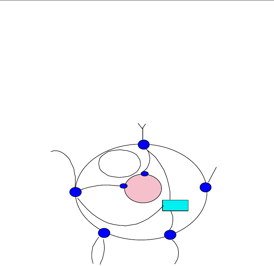
User Manual
Airbridge cBTS3612 CDMA Base Station System Description
2 Hardware Architecture
2-58
Systematic protection: Since information equipments are extensively connected and
lightning surge is everywhere, protection only on equipment and board level is not
enough. A systematic protection should be considered, including the equipment
office (site) where the BTS is located.
Probability protection: Lightning is random and lightning protection devices cannot
suppress all over-voltage and over-current. Although there is small probability of
destructive lightning, the cost of protection is considerable.
Multi-level protection: IEC 61312 divides the equipment premises area into several
lightning protection zones: LPZ0A, LPZ0B, LPZ1 and LPZ2, as shown in Figure
2-26.
LPZ2 EM field
further attenuation
LPZ0A is likely to be attacked by
direct lightning, with no attenuation
in the electromagnetic field
Antenna
Metal (pipe)
Equipment
Communication cable
Power cable
Hole (such as window)
Pole or fence
LPZ0B is not likely to be
attacked by direct lightning,with
no attenuation in the
electromagnetic field
LPZ1 is not likely to be attacked by
direct lightning, with no attenuation in
the electromagnetic field.
Figure 2-27 IEC 61312 division of lightning protection zone
BTS equipment is usually in LPZ1, and communication cables, power cables and
antennae are usually in LPZ0A. Different protection measures are taken for different
zones. The multi-level protection requires equipotential connection (equipotential
connection means the connection of lightning apparatus, metal devices, foreign
conductor, electrical appliances and telecommunication equipment located in the
area with conductors or surge protectors) to minimize potential difference between
metal parts and the systems.
Generally, to lower the probability of lightning attack to the BTS, the following three
aspects should be considered: protection system of the room (site) where BTS is
located, BTS internal lightning protection system, and their interoperation.
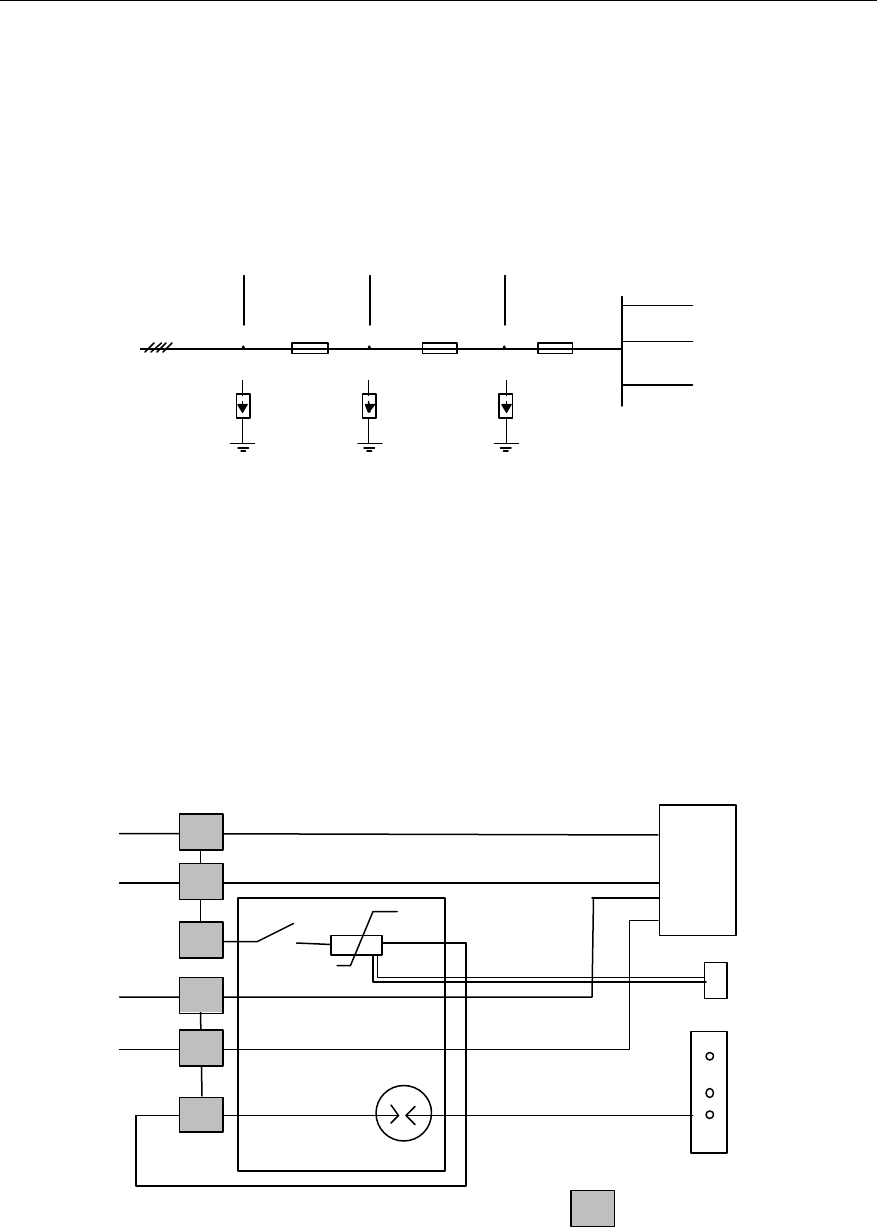
User Manual
Airbridge cBTS3612 CDMA Base Station System Description
2 Hardware Architecture
2-59
2.7.2 Lightning Protection for DC
I. Multi-level protection of power supply
The BTS power supply subsystem is normally in 5-level protection, as shown in
Figure 2-28.
.
.
.
3-phase AC
AC/DC
6kV 4kV 2.5 kV 1.5kV
Great power-absorbing
capability, slow
response, at cable inlet
of the room, optional
Normal power-absorbing
capability, quick
response, in front of
rectifier module
Low power-absorbing
capability, very quick
response, in rectifier
module
Level-1 protection Level-2 protection Level-3 protection Level-4 protection
Considerable
power-absorbing
capability, normal
response, at the AC
distribution point
Figure 2-28 Illustration of lightning protection of BTS power
II. Principle of DC lightning arrester
Level-5 protection is a built-in integrated lightning arrester on the cabinet-top box.
The operation principle is as shown in Figure 2-29.
EMI
-48V
GND Signal line
Wiring terminal
PGND
Lightning arrester
Figure 2-29 Illustration of lightning protection of BTS power
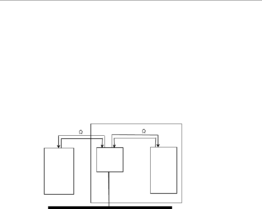
User Manual
Airbridge cBTS3612 CDMA Base Station System Description
2 Hardware Architecture
2-60
2.7.3 Lightning Protection for Trunk Line
I. Overview
Three kinds of trunk lines are supported in BTS: 75Ù coaxial cable (E1), 120Ù
twisted pair (E1) and optical fiber. Lightning protection is out of question if optical
fiber is used as the BTS is connected with fiber tail. For E1 trunk line, the BTS E1
surge protector (BESP) on top of the cabinet provides lightning protection.
II. Connection to BTS via E1 trunk line
The connection is shown in Figure 2-30.
BESP
BTS
Transmission
equipment
BCIM
75/120 75/120
Grounding bar of the room
Figure 2-30 Connection to BTS via trunk lines
III. BESP introduction
E1 interface protection of BTS is implemented through a BESP on top of the cabinet.
In consideration of the limited cabinet-top space or the convenience of installation,
two identical BESPs are used, each with 8 pairs (16 PCS) of E1 lightning protection
units, 1 DB37 connector and 2 DB25 connectors, as shown in Figure 2-31.
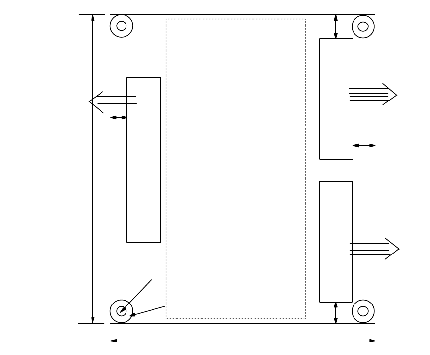
User Manual
Airbridge cBTS3612 CDMA Base Station System Description
2 Hardware Architecture
2-61
DB37
DB25 DB25
16 E1 lightning
protection units
128mm
128mm
Fixing holeФ3.5
PGNDФ10
Out from the
cabinet
(4 pairs of
E1s)
Into the
cabinet
(8 pairs of
E1s)
10mm
6mm
6mm
5mm
Out from the
cabinet
(4 pairs of
E1s)
Figure 2-31 Physical appearance of BESP
E1 lightning protection unit has two inbound lines connected with DB25, two
outbound lines connected with DB37, and one PGND. Here PGNDs of all lightning
protection units can be interconnected. DB37 is male connector and DB25 is female
connector, with 8 pairs of shielded E1 cables connected. 75Ù and 120Ù impedance
match is provided with the cables. The principle of lightning protection units is as
shown in Figure 2-32.
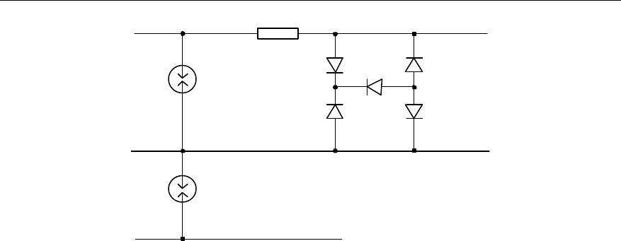
User Manual
Airbridge cBTS3612 CDMA Base Station System Description
2 Hardware Architecture
2-62
Core
Sheath
PGND
Lead in
DB25
Lead out
DB37
Figure 2-32 Principle of E1 lightning protection units
2.7.4 Lightning Protection for Antenna & Feeder Port
I. Lightning protection for RF antenna & feeder port
Antenna & feeder lightning protection is to protect against secondary lightning attack,
i.e. inductive lightning. Inductive lightning means that the feeder receives inductive
current at the moment of lightning attack, which may cause damage to the
equipment.
Inductive lightning can be prevented effectively in three ways:
l The feeder is grounded at three points.
l Antenna DC is grounded. The inductive current on the conductor of the feeder
can be discharged through the antenna.
l CDU/DFU's DC is grounded. The inductive current on the conductor of the
feeder can be discharged through CDU/DFU.
l When DDU is configured, lightning arrester should be used between the feeder
and indoor jumper.
With the above measures taken, up to 8kA lightning current can be endured.
II. Lighting protection for dual-satellite synchronization antenna & feeder
GPS/GLONASS antenna & feeder is protected with an additional lightning arrester
to prevent the damage caused by the lightning current induced on the core of the
antenna & feeder.
Lightning protection can be active or passive:
l Passive lightning protection: The low frequency lightning current is grounded
based on microwave principle to provide protection.
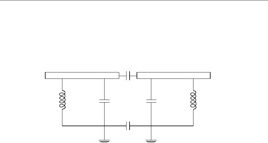
User Manual
Airbridge cBTS3612 CDMA Base Station System Description
2 Hardware Architecture
2-63
l Active lightning protection: A discharge tube is used as the lightning arrester.
When the voltage at both ends of the discharge tube comes to a specified value,
the two ends will be connected, hence the lightning protection is realized.
The dual-satellite synchronization antenna & feeder adopts passive lightning
protection. Its equivalent circuit is shown in Figure 2-33.
L1
12
C1
C2
C3 C4 L2
Figure 2-33 Lightning protection for BTS antenna & feeder port
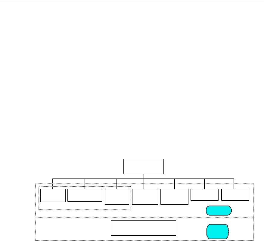
User Manual
Airbridge cBTS3612 CDMA Base Station System Description
3 Software Architecture
3-1
3 Software Architecture
3.1 Overall Architecture
cBTS3612 software consists of applications and bottom layer software in terms of
layer. And in terms of functional unit, there are main control software, O&M software,
clock software, BCIM software, BCPM software, BRDM software and BTRM
software.
Main control software, O&M software and clock software are compiled together,
running on BCKM. Other software runs on their corresponding boards.
cBTS3612 software architecture is as shown in Figure 3-1.
Lower layer
software
Application
cBS3612 software
O&M software
Main control
software Clock
software BCIM
software BCPM
software
Running on BCKM
Operating system and lower
layer driver
BRDM software BTRM software
Figure 3-1 cBTS3612 software architecture
I. cBTS3612 applications
This part mainly realizes layered protocol of radio links and Abis interface protocol,
exercises real-time management over radio resources and transmission equipment,
as well as performs operation & maintenance to BTS equipment. The function of
each software module will be detailed in “3.2 Module Description”.
II. cBTS3612 bottom layer software
This part operates on a unified software platform. Bottom layer software includes
operating system and bottom layer drivers. The operating system is a
well-developed real-time multi-task imbedded operating system, which provides
highly effective and reliable operations such as task dispatching, message
management, timer management and memory management. The bottom layer

User Manual
Airbridge cBTS3612 CDMA Base Station System Description
3 Software Architecture
3-2
drivers provide basic functions for the upper layer to operate the physical devices
and for the calling by applications.
3.2 Module Description
3.2.1 Main Control Software
I. Function
The main control software is primarily used for the control of traffic flow. It
communicates with BSC through Abis interface, and with BCPM, BTRM, OMU
(operation & maintenance software) interfaces inside the BTS. BTS is connected
with BSC through the main control software, jointly performing radio resources
management on air interface.
II. Structure
The structure of the main control software is shown in Figure 3-2.
Main control software
Cell configuration and
message update Channel
management Active/standby
switchover Operation &
maintenance
Resource
management
Figure 3-2 Structure of main control software
III. Software units
1) Resource management
This unit consists of four sub-modules:
l Resource status management: When BTS resource status changes, the main
control software reports to BSC the current status of BTS resource, which will
trigger BSC to perform logic configuration operation to BTS. At the same time,
BTS regularly reports its resource status to BSC so that the logic resource
status of BTS and BSC are consistent. Logic resources include cells, carriers,
forward channels and reverse channels in the channel resource pool.
l Resource measurement report: Main control software submits the cell public
parameter measurement report received from BTRM to BSC. Specific
parameters include RSSI, carrier transmit power, etc.

User Manual
Airbridge cBTS3612 CDMA Base Station System Description
3 Software Architecture
3-3
l Resource blocking function: cells, carriers or channel elements can be blocked
or unblocked.
l Resource checking function: Main control software checks the resources of
BCPM regularly, such as dedicated channels and common channels, to make
sure the resources allocated on both sides are identical.
2) Cell configuration and message update
This unit comprises three sub-modules:
l Cell configuration function: BSC makes logic configuration to the cell according
to the availability status of the logic resource reported by BTS. Specifically, they
are carrier attribute configuration of BTRM and cell common channel attribute
configuration of BCPM. Carrier attribute configuration parameters include
carrier band, carrier absolute frequency point number and carrier transmit gain.
Cell common channel attribute configuration parameters include BASE_ID, cell
ID, pilot PN sequence offset, cell gain, common channel number and attribute
(including pilot type, pilot gain, SCH gain, QPCH quantity, QPCH gain, QPCH
rate, PCH quantity, PCH gain, PCH rate, and ACH quantity).
l Overhead message update: after cell configuration, when the cell logic resource
changes, it is necessary to update the overhead message of the cell. Overhead
message includes system parameter message, access parameter message
and synchronization channel message.
l Cell breath control: when the traffic load of adjacent cells is not balanced, BSC
activates the cell breath control. The main control software reconfigures the cell
attribute parameters as required by BSC, to perform cell breath function.
3) Channel management
This unit comprises 6 sub-modules:
l Paging channel message processing: transmit the paging channel message to
corresponding BCPM according the parameters such as cell ID, absolute
frequency point number and PCN.
l Access channel message processing: Main control software sends the access
channel message received from BCPM access channel to BSC.
l Channel allocation and release: when a dedicated channel is to be set up, the
main control software will first check information such as the carrier absolute
band of the dedicated channel, channel type, RC, rate, frame length, and
whether it is a branch of the existing channel for a softer handoff, then distribute
channel resources in the corresponding channel resource pool and send
message instruction to BCPM to set up the channel. Similarly, when a channel
is to be released, the main control software first sends message instruction to
BCPM to release the channel, then returns the released channel to
corresponding channel resource pool. When a dedicated channel is to be set up

User Manual
Airbridge cBTS3612 CDMA Base Station System Description
3 Software Architecture
3-4
or released, main control software needs to distribute or release the AAL2 traffic
link of the corresponding Abis interface.
l Physical channel modification function: in the process of a communication over
a dedicated channel, BSC can modify some parameters of this channel on the
physical layer. The parameters include: long code mask, reverse pilot gate
control rate, forward power control mode and MS pilot gain. After receiving the
message from BSC, the main control software identifies the BCPM number of
the dedicated channel, and sends message to the BCPM board, instructing the
modification of physical parameters.
l Common channel mutual-aid function: when part of channel elements in a
channel resource pool are damaged, and part of or all of common channels in
this resource pool are unavailable, the main control software will attempt to
move the affected common channels onto some available channels. At the
same time, BCKM will send message to BCPM, requesting it to re-establish
these channels.
l Transmission delay report function: when the BTS seizes a reverse dedicated
channel, or after the acquisition the air interface delay from the MS to the BTS
changes over 1 chip, BCPM will report to main control software about the air
interface delay of this dedicated channel. Then main control software forwards
the channel delay information to BSC.
4) Active/standby switchover
To improve the system reliability, main control software works in active/standby
mode. The active main control software backs up call data to the standby in real time.
When the active equipment gets faulty, active/standby switchover will be conducted.
Therefore the communication can continue on the channel without any interruption.
5) Operation & maintenance
The O&M functions include data configuration, status report, interface tracing, fault
alarm, restart control, switchover control, log transfer and process reporting.
3.2.2 O&M Software
I. Function
Operation & maintenance software unit (OMU) is the maintenance control part of
cBTS3612. Other software modules in the BTS have their own int erfaces to the
OMU.
OMU monitors the operation of BTS. It is the bridge between the O&M center (OMC)
and all devices of cBTS3612. OMU is connected upward with OMC and downward
with the function units of BTS. On one hand, OMU receives instructions from OMC,
converts them into control unit instructions and sends them to the function units. On

User Manual
Airbridge cBTS3612 CDMA Base Station System Description
3 Software Architecture
3-5
the other hand, OMU receives status report and alarm report from the function units,
make proper processing and report to OMC.
II. Structure
The structure of the operation & maintenance software is shown in Figure 3-3.
O&M software
Status
management Data
configuration Test
management Interface tracing
Software loading
Fault
management
Log management Maintenance
console interface
Other functions
Figure 3-3 Structure of O&M software
III. Introduction to software units
1) Software downloading
Software of all parts of BTS (including O&M software) can be downloaded remotely.
So it is not necessary to upgrade the software on the site of BTS.
2) Status management
This unit monitors the operation status of BTS boards, and perform block/unblock
opertions for the channels.
3) Data configuration
This part configures the operation parameters of BTS boards, including BTS
attributes, BTRM attributes and BCPM attributes, and manages Abis interface
circuit.
4) Test management
It is responsible for vairous tests of BTS equipment, including functional test of the
boards, pre-warning of faults and location of faults.
5) Interface tracing
This part traces the air interface messages, or other interface messages inside BTS,
to help locate faults.
6) Fault management
This part monitors BTS internal alarms (such as board alarms) and environmental
alarms (such as temperature, humidity, fire alarm). For serious alarms, the OMU can
take protective measures such as shutting down the equipment to avoid further
damage.
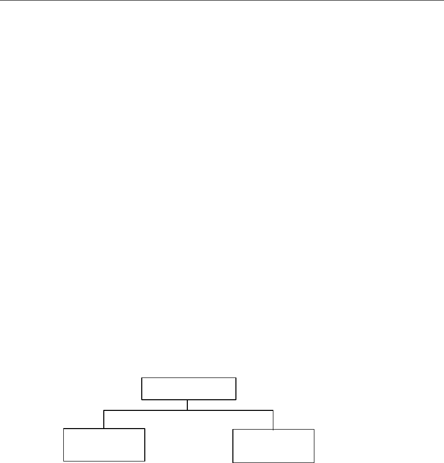
User Manual
Airbridge cBTS3612 CDMA Base Station System Description
3 Software Architecture
3-6
7) Log management
Equipment operations and abnormal information are recorded to help locate faults.
8) Maintenance console interface
With the local MMI, the user can perform operation & maintenance locally to the BTS
via the Ethernet.
9) Other functions
Other functions include active/standby switchover, debugging, etc.
3.2.3 Clock Software
I. Funciton
The primary function of the clock software is to follow the standard 1PPS pulse
signal output by the clock reference source module and GPS/GLONASS time
information output from the serial port, and generate various clock signals
synchronous with GPS/GLONASS system with the software phase-locking
algorithm.
II. Structure
Structure of clock software is shown in Figure 3-4.
Clock software
Operation &
maintenance
Service
application
Figure 3-4 Structure of clock software
III. Introduction to software units
1) Service application
This unit consists of three functional sub-modules:
l Reference clock source serial port communication processing sub-module: the
clock software supports three reference clock sources inputs: GPS, GLONASS
and external input. The sub-module gets GPS time information from the serial
port of the clock source (the present system uses GPS clock source), and
distributes to the system via OMU.

User Manual
Airbridge cBTS3612 CDMA Base Station System Description
3 Software Architecture
3-7
l Software phase-locking sub-module: it combines the methods of hardware
counting and software phase-locking to provide GPS/GLONASS
synchronization clock signal for the system.
l Hardware phase-locking control sub-module: this sub-moduloe performs
initialization settings for the devices of hardware phase-locked loop (PLL).
2) Operation & maintenance
l Public part: process messages related to OMU interface, such as public query,
board self-check and related functions.
l Private part: impletement clock module operation parameter configuration,
status management, alarm collection, alarm processing and reporting.
3.2.4 BCIM Software
I. Function
The primary function of BCIM software is to set up ATM transmission link on Abis
interface between BTS and BSC, and perform transmission of signaling, traffic and
O&M information between the two through related protocol stack. Specifically, it
l Receives OMU configuration command and configures ATM transmission link
on Abis interface.
l In a frame of 128 cells, supports the maximum 8%1904kbit/s bandwidth of one
ATM transmission link.
l Supports up to 7 ATM transmission links between BTS and BSC, with the
bandwidth of each link being 1904kbit/s.
II. Structure
The structure of BCIM software is shown in Figure 3-5.
BCIM software
Operation &
maintenance
IMA processing
Figure 3-5 Structure of BCIM software
III. Introduction to software units
1) IMA processing
IMA (Inverse Multiplexing on ATM) processing includes: add or delete IMA link sets
and IMA links dynamically, add or delete UNI links.

User Manual
Airbridge cBTS3612 CDMA Base Station System Description
3 Software Architecture
3-8
2) Operation & maintenance
l Public part: process messages related to OMU interface, such as log
management, board self-check, public query, interface tracing, board software
loading, link test, and related functions.
l Private maintenance: perform management of E1/SDH interface, IMA state
machine and IMA configuration, BCIM board status management, alarm
collection, alarm processing and reporting.
3.2.5 BCPM Software
I. Function
The function of BCPM software is to make operation and control to channel
processors, specifically:
l Working with main control software to manage the traffic layer of BCPM.
l Common channel processing.
l Traffic channel processing.
II. Structure
The structure of BCPM software is shown in Figure 3-6.
BCPM software
Service
application Operation &
maintenance
Figure 3-6 Structure of BCPM software
III. Introduction to software units
1) Service application
This unit consists of 3 functional sub-modules:
l Control & management sub-module: the sub-module sets up or release
specified channels according to the control command sent from main control
software. At the same, it exercises management over cell configuration and
radio link.
l Common channel sub-module: under the control of the control & management
sub-module, this sub-module sets up or releases common channel. For forward
common channel, it dispatches messages and controls the corresponding
driver to send messages on the air at correct time. For the reverse common

User Manual
Airbridge cBTS3612 CDMA Base Station System Description
3 Software Architecture
3-9
channel, it receives reverse messages on the air, and forwards them to BSC
through the main control software.
l Dedicated channel sub-module: under the control of the control & management
sub-module, it sets up or releases traffic channel. For the forward dedicated
channel it receives data frames from BSC and sends them on the air at correct
time according to the power set in BSC. For reverse dedicated channel, it
receives reverse frame on the air interface, adds some information and sends
them to BSC.
2) Operation & maintenance
l Public part: process messages related to OMU interface, such as log
management, board self-check, public query, interface tracing, board software
loading, link test, and related functions.
l Private part: perform channel processing parameter configuration, status
management, alarm collection, alarm processing and reporting.
3.2.6 BRDM Software
I. Function
BRDM software is used to relay BTRM signaling and control baseband data. The
main functions are:
l Relay of signaling for up to 36 BTRMs (including main control signaling and
operation & maintenance signaling).
l Receiving OMU configuration command, controlling the relay of forward &
reverse baseband data.
II. Structure
The structure of BRDM software is shown in Figure 3-7.
BRDM software
Signaling trunk Operation &
maintenance
Figure 3-7 Structure of BRDM software
III. Introduction to software units
1) Signaling relay
This part performs BTRM signaling relay function, including two parts: BTRM
signaling relay and relay interface matching. According to the format and protocol

User Manual
Airbridge cBTS3612 CDMA Base Station System Description
3 Software Architecture
3-10
negotiated with BTRM software, it adapts signaling from OMU or BCKM and sends
them to BTRM, or adapts signaling from BTRM and sends them to OMU or BCKM.
2) Operation & maintenance
l Public part: process messages related to OMU interface, such as log
management, board self-checking, public query, interface tracing, board
software loading, link test, and related functions.
l Private part: perform functions such as baseband trunk link configuration,
BTRM signaling trunk link configuration, link quality monitoring, board status
management, alarm collection, alarm processing and reporting.
3.2.7 BTRM Software
I. Function
BTRM software exercises management over BTRM. The main functions include:
l Cell carrier configuration, carrier parameter measurement and transmit gain
compensation.
l Operation & maintenance over BTRM module.
l Ensuring the precision of BTRM clock through software phase-locking.
l Board device configuration, BFMM & environment monitor box management,
and optical link delay measurement.
II. Structure
The structure of BTRM software is shown in Figure 3-8.
BTRM software
Others Operation &
maintenance
Software
phase-lock
Signaling
processing
Figure 3-8 Structure of BTRM software
III. Introduction to software units
1) Signaling processing
This unit consists of 4 functional sub-modules:
l Carrier setting: BTRM software receives carrier configuration command from
main control software, and configures the frequency and power class of the
sector carrier.

User Manual
Airbridge cBTS3612 CDMA Base Station System Description
3 Software Architecture
3-11
l Public parameter measurement: BTRM makes a regular measurement of the
forward transmit power and Received Signal Strength Indication (RSSI), and
reports the measurement result to BCKM.
l Loopback test: BTRM software receives loopback test command from the main
control software and returns the test data. This function is used for testing the
logic link between BTRM and BCKM.
l Transmit path gain compensation: BTRM software modifies the gain of the
transmit path according to the change of ambient temperature and the present
working frequency, to ensure the stability of transmit power at antenna & feeder
port.
2) Software phase-lock
BTRM software phase-lock unit controls the thermostatic crystal oscillator with
software phase-locking algorithm so that the crystal oscillator can provide a clock
with satisfactory frequency and precision to the system.
3) Others
This part consists of 2 functional sub-modules:
l Optical fiber delay calculation: when the optical fiber is long, the delay of optical
link becomes significant. BTRM software can calculate the delay of the optical
link and reports the result to OMU so that OMU can make necessary phase
compensation.
l BFMM and environment monitor box management: BTRM software exercises
management over the BFMM and environment monitor box, including storing &
sending alarm information, sending control command and acquiring real-time
status.
4) Operation & maintenance
l Public part: process messages related to OMU interface such as log
management, board self-check, public query, interface tracing, board software
loading, link test, and related functions.
l Private part: control the parameter configuration and operation status of RF
system, monitor RF PLL status, and perform functions such as alarm collection,
alarm processing and reporting.
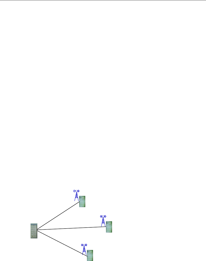
User Manual
Airbridge cBTS3612 CDMA Base Station System Description
4 System Function
4-1
4 System Function
This chapter describes the main functions of cBTS3612, including transmission
networking, call procedure, signaling processing, baseband processing, RF
functions, and operation & maintenance function.
4.1 Transmission Networking
cBTS3612 supports star networking, chain networking and tree networking.
Different networking modes are realized through the flexible configuration of BCIMs.
Each BCIM provides 8 E1 interfaces and each cabinet can be configured with 2
BCIMs, so total 16 E1s can be configured.
I. Star networking
Star networking is the widely used, especially in the densely populated urban area.
Start networking is as shown in Figure 4-1.
In this mode, each BTS is directly connected with BSC with an E1 trunk line. The
networking is simple and maintenance is easy. Signals go through less links and the
line is more reliable. Future expansion is easier. However, this mode requires much
more transmission lines than any other mode.
BSC
BTS
BTS
BTS
E1
E1
E1
Figure 4-1 BTS star networking
II. Chain networking
Chain networking of the BTS is shown in Figure 4-2. It is applicable to sparsely
populated stripe areas, e.g. along the highways and railways.
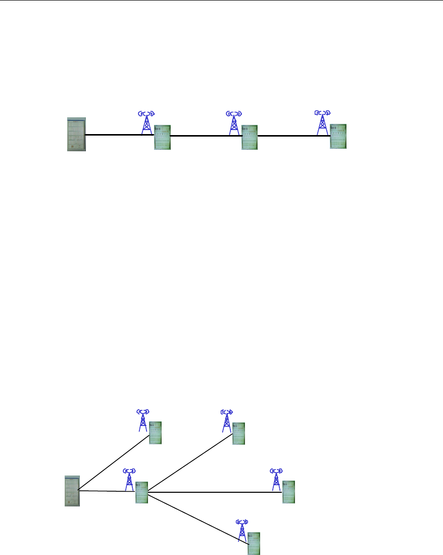
User Manual
Airbridge cBTS3612 CDMA Base Station System Description
4 System Function
4-2
Chain networking is a perfect solution to certain requirements and can save the
transmission resources.
The disadvantage of this mode is that signals should pass quite a few network
sections, making the line less reliable. The nodes cascaded should not be more
than 3.
BSC
BTS BTS
BTS
E1 E1 E1
Figure 4-2 BTS chain networking
III. Tree networking
Tree networking mode applies to the area where network structure, site and
subscriber distribution are complicated, such as the area where users are not evenly
distributed. Tree networking is as shown in Figure 4-3.
In this mode, signals go through many links, so the line reliability is low, and
implementation and maintenance are difficult. In addition, the fault in the upper-level
BTS may affect the normal operation of the lower-level BTSs. Expansion is not easy
and may cause substantial network reconstruction. However, tree networking
requires much less transmission lines than star networking. The cascaded BTSs
should not be more than 3 levels, i.e. the depth of the tree should not exceed 3
layers.
BSC
BTS
BTS
BTS
E1
E1
E1
BTS
BTS
E1
E1
Figure 4-3 BTS tree networking
It is common practice that the above three modes be used together. Proper
application of different modes inproves service quality and saves investment on the
transmission equipment.
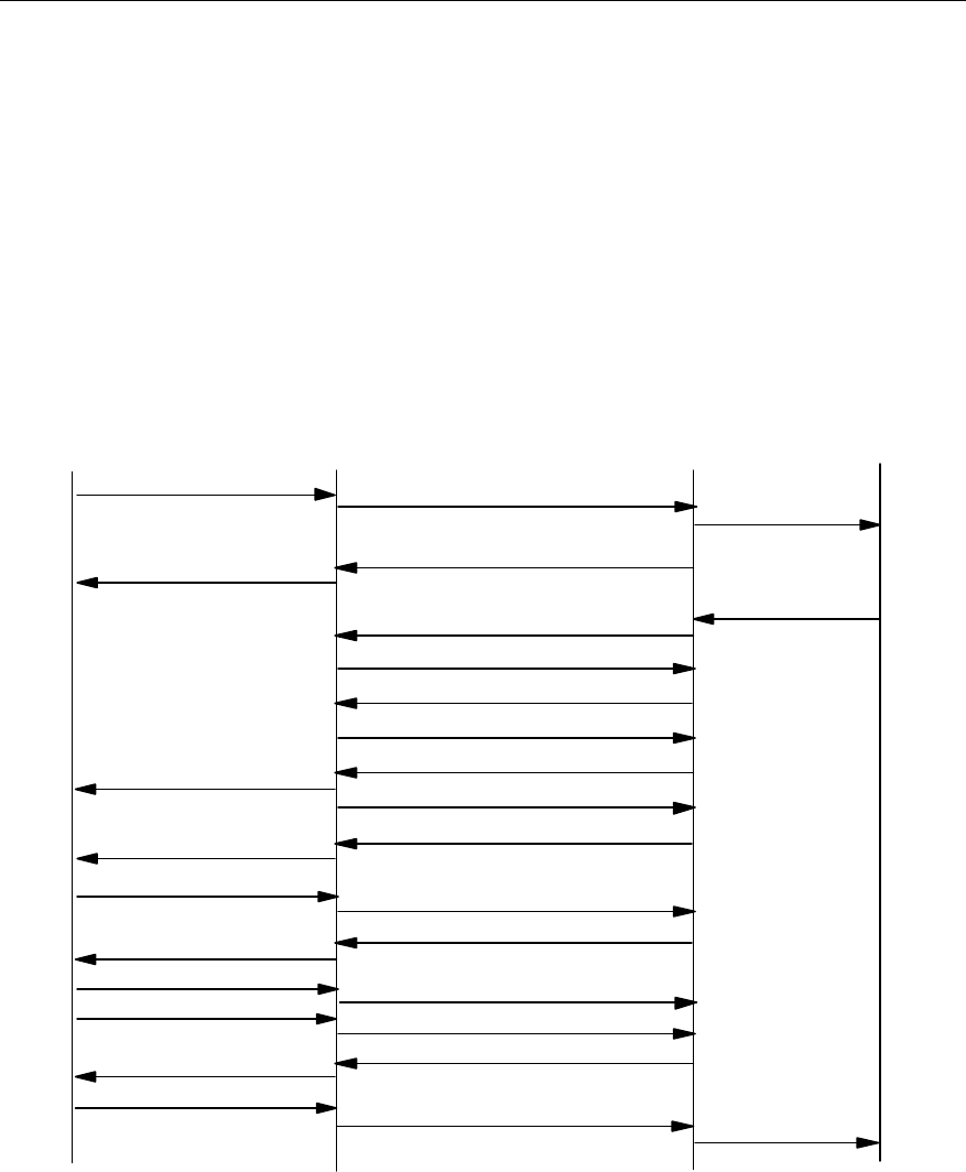
User Manual
Airbridge cBTS3612 CDMA Base Station System Description
4 System Function
4-3
4.2 Call Procedure
Call procedure mainly includes speech service call procedure and data service call
procedure. This section gives some typical examples to introduce the MS call
procedures.
4.2.1 Speech Service Call Procedure
I. MS-originated call (MOC)
MS-originated call procedure is illustrated in Figure 4-4.
MS BTS BSC
Origination Msg Abis-ACH Msg Transfer(ORM)
Abis-PCH Msg Transfer(Base Ack)
Base Ack Order
Abis-BTS Setup
Abis-Connect
Abis-Connect Ack
Abis-BTS Setup Ack
Abis-IS2000 FCH Fwd(Null data)
Null Traffic Data Abis-IS2000 FCH Rvs(Idle data)
Abis-PCH Msg Transfer(ECAM)
ECAM
Traffic Channel Preamble Abis-IS2000 FCH Rvs(Preamble)
Abis-IS2000 FCH Fwd(Base Ack)
Base Ack Order
Idle TCH Data Abis-IS2000 FCH Rvs(Idle Data)
MS Ack Order Abis-IS2000 FCH Rvs(Ms Ack)
Abis-IS2000 FCH Fwd(Service Connect)
Service Connect Msg
Service Connect Complete Abis-IS2000 FCH Rvs(Ser Conn Comp)
CM Service Req
Assignment Complete
MSC
Assignment Req
ACH
PCH
TCH
PCH
TCH
TCH
TCH
TCH
TCH
TCH
(1)
(2)
(3)
(4)
(5)
(6)
(7)
(8)
(9)
(10)
(11)
(12)
(13)
(14)
(15)
(16)
(17)
Figure 4-4 MS-originated call procedure
1) MS sends "Origination Message" on access channel. On receiving the
message, BTS sends “Abis-ACH Msg Transfer” message to BSC.
2) BSC sends “CM Service Request” message to MSC, to request service
assignment. Meanwhile, BSC sends “Base Ack” order to BTS via “Abis-PCH
Msg Transfer” message. BTS sends “Base Ack Order” on paging channel to the
MS.

User Manual
Airbridge cBTS3612 CDMA Base Station System Description
4 System Function
4-4
3) MSC sends "Assignment Request" message to BSC to request BSS to assign
radio resources.
4) BSC sends “Abis-BTS Setup” message to BTS, to request BTS to allocate
radio resources for the call.
5) BTS sends “Abis-Connect” message to BSC, to establish Abis service
connection.
6) BSC sends “Abis-Connect Ack” to BTS in response to the “Abis-Connect”
message.
7) After resources allocation, BTS sends “Abis-BTS Setup Ack” message to BSC.
8) BSC sends “Abis-IS2000 FCH Fwd” message to BTS, and orders BTS to send
null frame to MS.
9) After receiving “Abis-IS2000 FCH Fwd” message, BTS sends idle frame to BSC
via “Abis-IS2000 FCH Rvs” message, and performs Abis link delay adjustment.
10) BSC sends channel assignment message to BTS via “Abis-PCH Msg Transfer”
message. BTS forwards the channel assignment message to MS on paging
channel.
11) MS begins to send traffic channel preamble on the assigned reverse traffic
channel. After BTS captures the preamble, it sends traffic channel preamble to
BSC via “Abis-IS2000 FCH Rvs” message.
12) After BSC receives traffic channel preamble from MS, BSC sends "Base Ack”
order to BTS via “Abis-IS2000 FCH Fwd” message; BTS will send “Base Ack
Order” to MS on the forward traffic channel.
13) After MS receives “Base Ack Order”, it stops sending traffic channel preamble
and starts to send data frame.
14) After MS receives “Base Ack Order”, it sends “MS Ack Order” to BTS. BTS
forwards the message to BSC via “Abis-IS2000 FCH Rvs” message.
15) On receiving “MS Ack” order, BSC sends "Service Connect" message to BTS
via “Abis-IS2000 FCH Fwd” message, then BTS forwards the message to MS.
MS starts to handle the traffic according to the designated service
configuration.
16) To respond to service connection message, MS sends "Service Connect
Complete" message.
17) On receiving the "Service Connect Complete" message, BSC sends
"Assignment Complete" message to MSC.
II. MS-terminated call (MTC)
MS-terminated call procedure is shown in Figure 4-5.
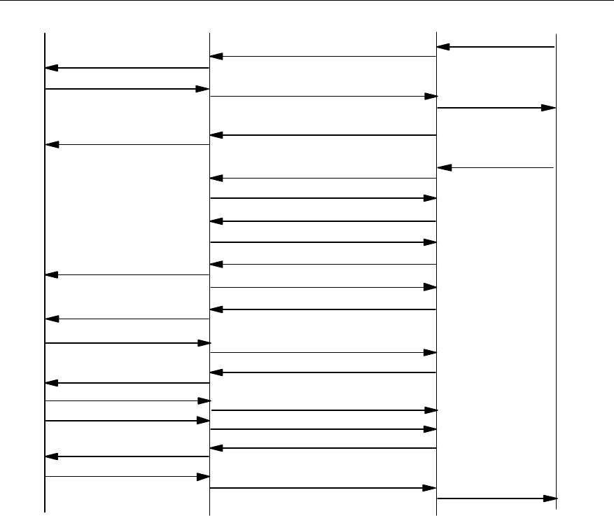
User Manual
Airbridge cBTS3612 CDMA Base Station System Description
4 System Function
4-5
MS BTS BSC
Paging Response Abis-ACH Msg Transfer(PRM)
Abis-PCH Msg Transfer(Base Ack)
Base Ack Order
Abis-BTS Setup
Abis-Connect
Abis-Connect Ack
Abis-BTS Setup Ack
Abis-IS2000 FCH Fwd(Null data)
Null Traffic Data Abis-IS2000 FCH Rvs(Idle data)
Abis-PCH Msg Transfer(ECAM)
ECAM
Traffic Channel Preamble Abis-IS2000 FCH Rvs(Preamble)
Abis-IS2000 FCH Fwd(Base Ack)
Base Ack Order
Idle TCH Data Abis-IS2000 FCH Rvs(Idle Data)
MS Ack Order Abis-IS2000 FCH Rvs(Ms Ack)
Abis-IS2000 FCH Fwd(Service Connect)
Service Connect Msg
Service Connect Complete Abis-IS2000 FCH Rvs(Ser Conn Comp)
CM Service Req
Assignment Complete
MSC
Assignment Req
Paging Request
Abis-PCH Msg Transfer(GPM)
GPM (1)
(2)
(3)
(4)
(5)
(6)
(7)
(8)
(9)
(10)
(11)
(12)
(13)
(14)
(15)
(16)
(17)
(18)
(19)
(20)
PCH
ACH
PCH
TCH
PCH
TCH
TCH
TCH
TCH
TCH
TCH
Figure 4-5 MS-terminated call procedure
1) MSC sends "Paging Request" to BSC.
2) BSC constructs General Paging Message (GPM), embeds it into”Abis-PCH
Msg Transfer” message, then sends it to BTS. BTS sends the GPM on the
paging channel.
3) After MS receives paging message, it sends "Paging Response" message
(PRM) to BTS. BTS forwards it to BSC in “Abis-ACH Msg Transfer” message.
4) BSC sends “CM Service Request” message to MSC, to request service
assignment.
5) BSC sends “Base Ack” order to BTS via “Abis-PCH Msg Transfer” message.
BTS sends the “Base Ack” order on the paging channel.
6) MSC sends assignment request message to BSC, to request BSS to assign
radio resources.
7) BSC sends “Abis-BTS Setup” message to BTS, to request BTS to allocate
radio resource for the call.
8) BTS sends “Abis-Connect” message to BSC, to establish Abis service
connection.

User Manual
Airbridge cBTS3612 CDMA Base Station System Description
4 System Function
4-6
9) BSC sends “Abis-Connect Ack” to BTS in response to “Abis-Connect”
message.
10) BTS completes resource allocation, and sends “Abis-BTS Setup Ack” message
to BSC.
11) BSC sends “Abis-IS2000 FCH Fwd” message to BTS, to order BTS to send null
frame to MS.
12) After receiving “Abis-IS2000 FCH Fwd” message, BTS sends null frame to BSC
via “Abis-IS2000 FCH Rvs” message, and performs Abis link delay adjustment.
13) BSC sends channel assignment message to BTS via “Abis-PCH Msg Transfer”
message. BTS forwards the message to MS on paging channel.
14) MS begins to send traffic channel preamble on the assigned reverse traffic
channel. After capturing the preamble, BTS sends traffic channel preamble to
BSC via “Abis-IS2000 FCH Rvs” message.
15) After BSC receives the traffic channel preamble sent from MS, it sends “Base
Ack” order to BTS via “Abis-IS2000 FCH Fwd” message. BTS forwards the
order to MS over the forward traffic channel.
16) After MS receives “Base Ack” order, it stops sending traffic channel preamble
and starts sending data frame.
17) After MS receives “Base Ack” order, it sends “MS Ack” order to BTS. BTS
forwards the order to BSC via “Abis-IS2000 FCH Rvs” message.
18) After BSC receives “MS Ack” order, it sends service connection message to
BTS via “Abis-IS2000 FCH Fwd” message. BTS forwards the message to MS,
and then MS starts to handle the service according to the designated service
configuration.
19) To respond to service connection message, MS sends service connection
complete message.
20) After BSC receives the service connection complete message, it sends
assignment complete message to MSC.
4.2.2 Data Service Call Procedure
I. MS-originated data service
MS-originated data service procedure is shown in Figure 4-6.
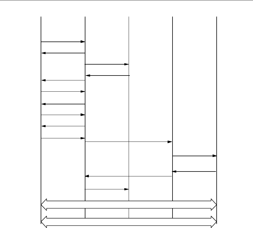
User Manual
Airbridge cBTS3612 CDMA Base Station System Description
4 System Function
4-7
A11 Registration
Request(Life time)
BSSMS
(1) Origination
(2) BS ACK
MSC
(3) CM Service Request
(11) A9-Setup -A8
(4) Assignment Request
PCF PDSN
(14) A9-Connect -A8
(15) Assignment Complete
Transmitting packet data
Establishing PPP connection , Mobile IP Registration
A11-Registration
Reply (Life time, Accept)
ECAM
(7) BS Ack Order
(8) MS Ack Order
(9) Service Connect Msg
(10) Service Connect
Cmp Msg
(6) Tch Preamble
(12)
(5)
(13)
Figure 4-6 MS-originated data service procedure
1) MS sends origination message to BS via the access channel on air interface.
2) After BTS receives origination message, it sends BS acknowledgement to MS.
3) BSC constructs a CM service request message and sends it to MSC.
4) MSC sends assignment request message to BSC, to request BTS to assign
radio resources.
5) BTS sends channel assignment message in the paging channel of air interface.
6) MS begins to send preamble in the assigned reverse traffic channel.
7) After acquiring the reverse traffic channel, BTS sends "BS ACK Order" to MS in
the forward traffic channel.
8) After receiving "BS ACK Order", MS sends "MS ACK Order", and transmits the
null service frame in the reverse traffic channel.
9) BTS sends service connection message/service selection response message to
MS, and designates the service configuration used for the call. MS starts to
handle the service according to the designated service configuration.

User Manual
Airbridge cBTS3612 CDMA Base Station System Description
4 System Function
4-8
10) After receiving service connection message, MS responds with one service
connection complete message.
11) BSC sends “A9-Setup-A8” message to PCF, to request to establish A8
connection.
12) PCF sends “A11-Registration-Request” to PDSN, to request to establish A10
connection.
13) PDSN accepts A10 connection establishment request, and returns
“A11-Registration-Reply” message to PCF.
14) PCF returns “A9-Connect-A8” message to BSC; connection between A8 and
A10 is established.
15) After both radio traffic channel and terrestrial circuit are established, BSC
sends assignment complete message to MSC.
16) MS negotiates with PDSN to establish PPP connection cooperatively. In the
case of Mobile IP access, Mobile IP connection will be established. PPP
message and Mobile IP message are transmitted in traffic channel, and are
transparent to BSC/PCF.
17) After PPP connection is established, the data service will enter connection
state.
II. SCH establishment
This section describes MS-originated Supplemental Channel (SCH) establishment
procedure, as for BSC-originated SCH establishment procedure, it is similar to
MS-originated SCH establishment procedure which differs in the trigger condition.
There is no special SCH release procedure when dynamically assigning SCH,
instead, BSC will determines SCH rate and duration, once the time is due, SCH will
be released. MS-originated SCH establishment procedure is shown in Figure 4-7.
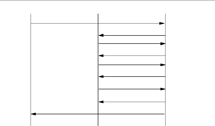
User Manual
Airbridge cBTS3612 CDMA Base Station System Description
4 System Function
4-9
MS BTS BSC
(2) Abis-BTS Setup
(3) Abis Connect
(4) Abis Connect Ack
(5) Abis-BTS Setup Ack
(1) Supplemental Channel Request Message
(6) Abis Burst Request
(7) Abis Burst Response
(8) Abis Burst Commit
(9) Extended Supplemental Channel Assignment Message
Figure 4-7 Reverse SCH establishment procedure
1) If the packet data call is established, MS may send “Supplemental Channel
Request Message” to BSC for establishing SCH channel.
2) BSC sends “Abis-BTS setup” to BTS, to request BTS to allocate radio resource
for the call.
3) After BTS establishes the channel, it sends “Abis-connect” to BSC.
4) BSC responds with “Abis-connect ack” to BTS.
5) After BTS establishes all of the channels, it sends “Abis-BTS setup Ack” to BSC,
indicating the completion of terrestrial circuit establishment.
6) BSC sends “Abis-Burst Request” to BTS to activate BTS.
7) BSC responds “Abis-Burst Response” message to BTS.
8) BSC sends “Abis-Burst Commit” to BTS, and BTS starts to transmit SCH.
9) BSC sends “Extended Supplemental Channel Assignment Message” and
assigns SCH channel for MS, so that the packet data service can be
transmitted at high speed in SCH channel.
4.3 Signaling Processing
BTS signaling processing serves two purposes:
l Implement interconnection of MS and BSS/CN on the air interface layer.
l Perform part of radio resource management function under the control of BSC.
Specifically, BTS signaling processing performs the following functions: signaling
processing on Abis physical layer and transmission layer, channel resource
management, Abis traffic link management, BTS logic operation & maintenance

User Manual
Airbridge cBTS3612 CDMA Base Station System Description
4 System Function
4-10
processing, common channel processing, dedicated channel setup and release,
traffic bearing and power control.
I. Signaling processing on Abis interface physical layer and transmission
layer
Abis interface physical layer utilizes IMA technology. BTS sets up or deletes IMA link
sets.
Abis interface data link layer utilizes ATM link. Signaling is adapted with AAL5 and
traffic is adapted with AAL2.
II. Channel resource management
BTS organizes channel resource with a resource pool and is responsible for the
allocation, release and management of the channel resource.
III. Abis traffic link management
BTS is responsible for assigning traffic link for Abis interface.
IV. BTS logic operation & maintenance
BTS processes the following logic operation & maintenance functions:
l Resource status indication
l Cell configuration function
l General message updating
l Cell breath control function
l Cell block/unblock function
l Radio measurement report function
V. Common channel processing
BTS is responsible for the setup and release of common channels and processing of
common channel messages. Common channels include paging channel, access
channel, etc.
VI. Setup and release of dedicated channel
BTS is also responsible for setup and release of dedicated channels.
VII. Traffic bearing
BTS processes Abis interface protocol, transmits the traffic channel data received
from the air interface to BSC, and transmits the traffic data that received from BSC
on the air interface.
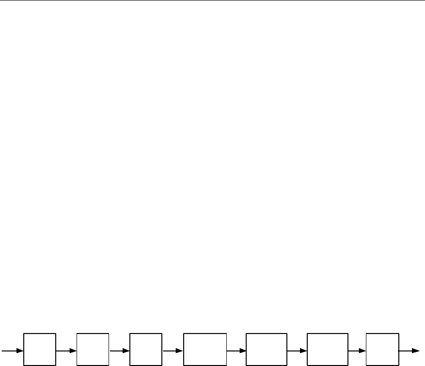
User Manual
Airbridge cBTS3612 CDMA Base Station System Description
4 System Function
4-11
VIII. Power control
BTS performs reverse quick power control and performs reverse outer loop power
control with the coordination of BSC.
4.4 Baseband Processing
Baseband processing performs physical layer function on Um interface, processing
baseband data of all full-duplex channels in CDMA system. In the forward direction
(transmitting direction), it fulfills channel encoding, rate adaptation, interleaving,
encryption, spreading spectrum and modulation. In the reverse direction (receiving
direction), it fulfills multi-path signaling demodulation, de-interleaving, channel
decoding and information bit extraction. For different RC, baseband processing is
different. But basically it can be summarized as follows:
I. Forward channel baseband processing
In CDMA forward channel, the baseband processing of one traffic channel includes
channel encoding, rate adaptation, block interleaving, long code scrambling, power
control bit insertion, Walsh code spreading spectrum, signal modulation and
baseband filtering, as shown in Figure 4-8.
Channel
encoding Rate
matching Block
interleave Long code
scrambling
Walsh code
spreading
spectrum
QPSK
modulation
Base
band
filtering
Figure 4-8 Baseband processing in forward channel
l Channel encoding
CDMA system uses convolutional code and Turbo code for channel encoding. Its
main function is error correction. Convolutional code is used for ordinary speech
service and Turbo code for high-speed data service.
l Rate adaptation
Since the system supports frames of different rates. The frame rates after channel
encoding are different. Rates should be adapted to ensure that the rate of frame
meets the requirement before entering the interleaver. In CDMA system, rate
adaptation is realized by symbol repetition and code puncturing.
l Block interleaving
The purpose of interleaving is to resist fast attenuation in the radio channel
environment.
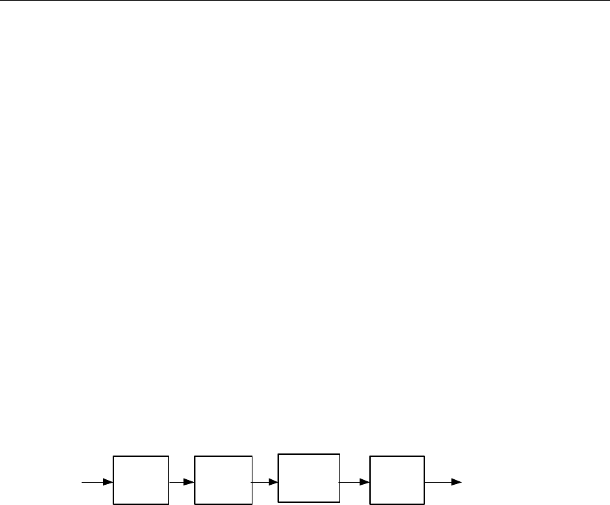
User Manual
Airbridge cBTS3612 CDMA Base Station System Description
4 System Function
4-12
l Long code scrambling
In the forward channel, long code scrambling is used to scramble the user data to
provide encryption function.
l Walsh code spreading
In the forward channel, Walsh code is used to identify each user.
l QPSK modulation
Quadrature Phase Shift Keying (QPSK) modulation is used in the forward channel.
PN short code is used in the modulation for scrambling and providing cell ID.
l Baseband filtering
This process implements pulse shaping without inter-code interference and
suppression of out-band signal.
II. Reverse channel baseband processing
Baseband processing in the reverse channel includes multi-path signal
demodulation, signal de-interleaveing, channel decoding, extraction of frame
information data, as shown in Figure 4-9.
Multi-path
signal
demodulation De-interleave Channel
decoding
Extract
information
bit
Figure 4-9 Reverse channel processing flow
1) Multi-path demodulation
With Rake technology, BTS can demodulate the radio multi-path signals and
effectively combine multi-path energy.
2) De-interleaving
Signals received from an MS have been interleaved, so de-interleaving must be
performed by BTS to recover the signals.
3) Channel decoding
MS uses convolutional code or Turbo code for channel encoding before
transmission, while BTS decodes with Viterbi decoder or Turbo decoder at the
receiving end based on the channel code type of the MS.
4) Extraction of frame information data
When transmission, MS adds Cyclic Redundancy Check (CRC) bits and a number
of all-zero tail bits at the end of information bits to compose a transmitting frame. On
receiving the frame, BTS performs CRC check and removes the non-information bit

User Manual
Airbridge cBTS3612 CDMA Base Station System Description
4 System Function
4-13
(CRC check bit and end bit) to get the information bits, then sends them to the
higher layer for processing.
4.5 RF Functions
cBTS3612 RF functions meet the requirements of TIA/EIA IS-97-D protocol. It
features high transmission power, high sensitivity, flexible configuration, easy
operation & maintenance, cell breath and diversity receiving.
4.5.1 Power Control
CDMA system is a self-jamming system, in which every subscriber is an interference
source to other subscribers. If it is possible to ensure that every MS transmits the
minimum power it needs, the whole system capacity can be the largest. Therefore,
power control directly affects the system capacity and the service quality.
I. Purpose
The purpose of the power control is to
l Ensure conversation quality, meanwhile restrict the transmitting power on the
forward and reverse links, thus minimizing the system interference.
l Overcome the far-near effect caused by the freely distributed mobile stations,
so the signals of mobile stations whose distances to the BTS are different can
reach the BTS with the same power.
l Realize the system soft capacity control.
l Prolong MS battery life.
l Minimize MS radiation to the human body.
II. Types
Power control can be divided into forward power control and reverse power control.
The forward power control is used to control BTS’s transmit power, while the reverse
power control aims to control MS’s transmit power.
1) Forward power control
Forward power control has various methods, whose applications are subject to the
MS protocol version and the system parameters.
l PMRM (Power Measurement Report Message)
When the MS adopts PMRM power control method, it will determine the method and
frequency of reporting PMRM in accordance with the received control message of
the system parameter message.
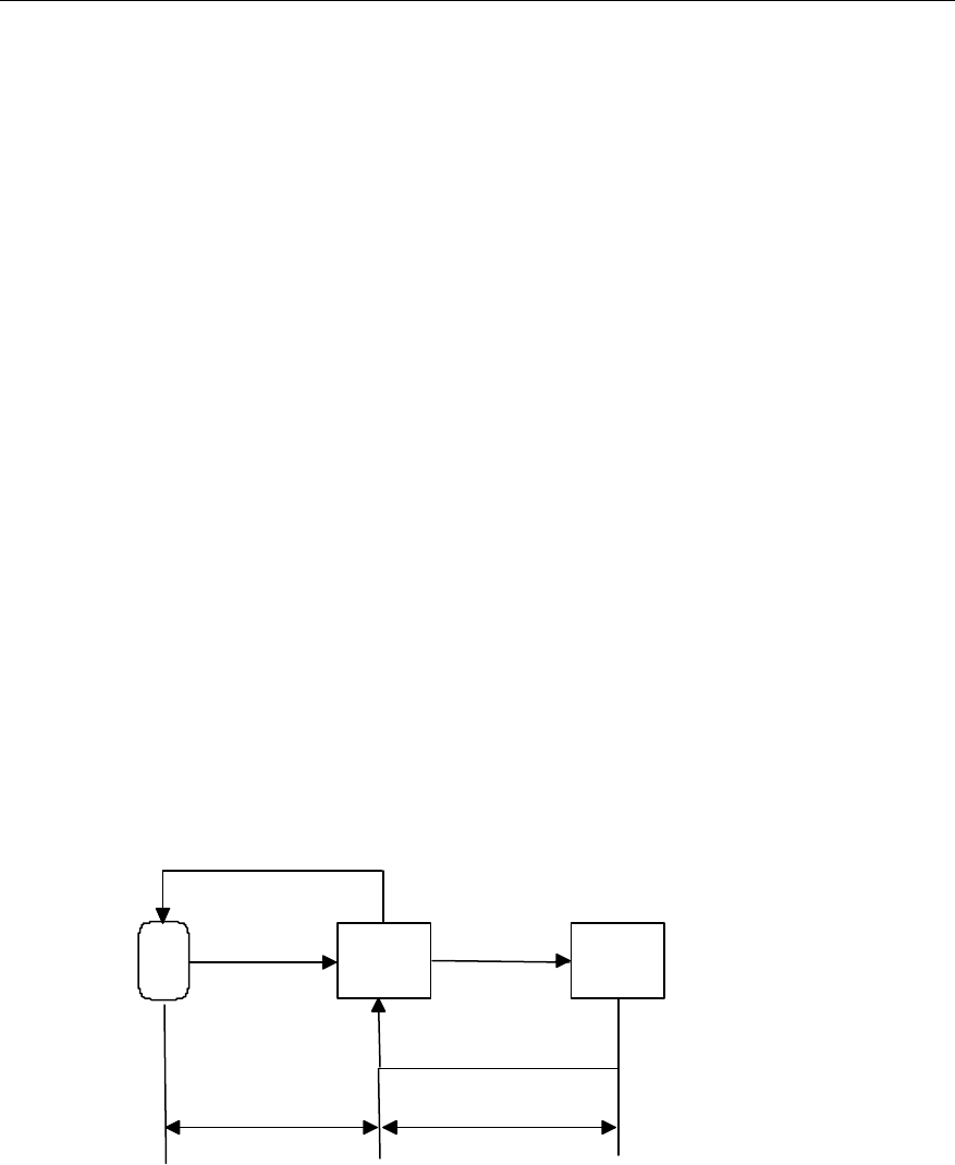
User Manual
Airbridge cBTS3612 CDMA Base Station System Description
4 System Function
4-14
l EIB (Erasure Indicator Bit) method
When the MS adopts EIB power control method, it will detect forward frame quality,
and feed back the information to the BTS via EIB. The BTS will adjust the transmit
power according to EIB information.
l Forward quick power control
MS will adjust BTS power according to power control bit (the maximum speed can
reach 800bit/s). In cdma2000 1X system, large data service is supported. Therefore,
the requirement on forward power control is increasingly strict. The forward quick
power control method can control forward channel transmit power accurately, so as
to reduce interference and improve the capacity.
2) Reverse power control
Reverse power control includes open-loop power control and closed-loop power
control. The closed-loop power control can be sub-divided into inner loop power
control and outer loop power control.
l Open-loop power control method
The MS will determine transmitting power intensity to access the BTS according to
the received pilot signal strength.
l Closed-loop power control method
The BTS issues power control command to the MS, and performs the adjustment
according to MS feedback. The principle of closed-loop power control is shown in
Figure 4-10.
MS BTS BSC
Eb/Nt FER
Power control bit
Eb/Nt Changing quantity
Internal loop External loop
Figure 4-10 Closed-loop power control
Inner loop power control: the BTS will issue power control bit according to the
received Eb/Nt.
Outer power control: the BSC will adjust Eb/Nt setting value according to the Frame
Error Rate (FER) of the received reverse signal. Then the BTS will use the newly set

User Manual
Airbridge cBTS3612 CDMA Base Station System Description
4 System Function
4-15
Eb/Nt value to issue power control bit, thus the purpose of indirectly controlling the
MS is achieved.
4.5.2 Handoff
I. Types
The handoff can be divided into the following three types according to the different
processing flow:
l Hard handoff
The MS will firstly interrupt the connection with the previous BTS, then set up the
connection with the new BTS.
l Soft handoff
When the MS establishes the communication with a new BTS, it will not release the
connection with the previous BTS.
l Softer handoff
It is the soft handoff occurred among different sectors in the same BTS.
II. Purpose
According to the purpose, the handoff can be divided into three types: rescue
handoff, better cell handoff and traffic handoff.
l Rescue handoff
When the MS is leaving the cell coverage area and the conversation quality is
unbearably poor, the handoff occurs in order to avoid the interruption of the call.
l Better cell handoff
If the rescue handoff condition is not triggered, this handoff may occur if
conversation quality or network performance can be improved. The handoff is called
better cell handoff because there is better cell for communication.
l Traffic handoff
This kind of handoff occurs when one cell is congested due to its heavy load and the
adjacent cell is relatively idle. This mainly results from traffic peak within short time
in a limited area due to some special events (such as sports, exhibition, etc).
4.5.3 Flexible Configuration
BTS supports the combination of three cabinets, so the maximum capacity can
reach 36 sector-carriers. BTS supports 1~12 carriers for each sector, omni or
directional coverage mode, and the configuration of 1~6 sectors. BTS can also

User Manual
Airbridge cBTS3612 CDMA Base Station System Description
4 System Function
4-16
control the sensitivity of the receive path and the transmit power to ensure that the
forward link and the reverse link are balanced in the system.
4.5.4 Radio Configuration and Channel Support
I. Radio configuration (RC)
Um interface supports cdma2000 1X, and is compatible with IS -95A/B. The
spreading rate is 1.2288Mcps.
The cdma2000 1X physical layer supports multiple radio configurations. Each radio
configuration supports the frames of the different rate sets, and possesses different
channel configuration and spreading spectrum structure. The supported
transmission combinations include:
l Forward RC1, and reverse RC1;
l Forward RC2, and reverse RC2;
l Forward RC3 or RC4, and reverse RC3;
l Forward RC5, and reverse RC4.
With the different RC, cdma2000 1X presents different capabilities. RC1 and RC2
are compatible with IS-95A/B.
Each RC supports different traffic channel data rate. The specific data rates are
listed in Table 4-1 and Table 4-2.
Table 4-1 Forward channel rates
Channel type Channel rate (bit/s)
F-SYNCH 9600
F-PCH 9600, or 4800
F-QPCH 4800, or 2400
RC3 or RC4 9600 (20ms frame)
F-DCCH RC5 14400 (20ms frame)
RC1 9600, 4800, 2400, or 1200
RC2 14400, 7200, 3600, or 1800
RC3 or RC4 9600, 4800, 2700, or 1500 (20ms frame)
F-FCH
RC5 14400, 7200, 3600, or 1800 (20ms frame)
RC1 9600
F-SCCH RC2 14400
RC3 153600, 76800, 38400, 19200, or 9600 (20ms frame)
RC4 307200, 153600, 76800, 38400, 19200, or 9600(20ms frame)
F-SCH
RC5 230400, 115200, 57600, 28800, or 14400 (20ms frame)
Table 4-2 Reverse channel rates
Channel type Channel rate (bit/s)
R-ACH 4800
RC3 9600(20ms frame)
R-DCCH RC4 14400(20ms frame)
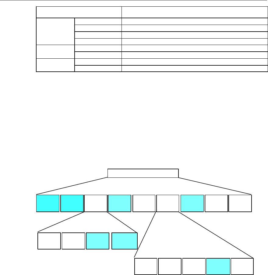
User Manual
Airbridge cBTS3612 CDMA Base Station System Description
4 System Function
4-17
Channel type Channel rate (bit/s)
RC1 9600, 4800, 2400, or 1200
RC2 14400, 7200, 3600, or 1800
RC3 9600, 4800, 2700, or 1500 (20ms frames)
R-FCH
RC4 14400, 7200, 3600, or 1800 (20ms frames)
RC1 9600
R-SCCH RC2 14400
RC3 153600, 76800, 38400, 19200, or 9600 (20ms frame)
R-SCH RC4 307200, 153600, 76800, 38400, 19200, or 9600 (20ms frame)
II. Physical channel configuration
On Um interface is defined series of physical channels, which are divided into
different types according to the channel features. Different RCs support different
channels.
1) Forward physical channel
The configuration of forward physical channel is shown in Figure 4-11.
F-TCH
Forward CDMA channel
F-CACH F-CPCCH F-PICH F-CCCH
F-DCCH F-FCH F-PC F-SCCH F-SCH
F-PICH F-TDPICH F-APICH F-ATDPICH
F-SYNCH F-BCH F-PCH F-QPCH
Sub-channel (RC1~2) (RC3~5)
Figure 4-11 Forward physical channels
l F-CACH (Forward Common Assignment Channel)
F-CACH is specially used for transmitting the assignment information in quick
response to the reversed channel, and provides the support for random access
packet transmission in the reversed link. F-CACH controls R-CCCH (Reverse
Common Control Channel) and F-CPCCH in Reservation Access Mode, and
provides the quick acknowledgement in power-controlled access mode. In addition,
it also provides congestion control function.
l F-CPCCH (Forward Common Power Control Channel)
F-CPCCH is used in the system to support multiple R-CCCH and R-EACH (Reverse
Enhanced Access Channel) to perform power control.

User Manual
Airbridge cBTS3612 CDMA Base Station System Description
4 System Function
4-18
l F-PICH (Forward Pilot Channel)
Signals are transmitted on F-PICH all the time. The BTS will transmit a fixed signal
in the pilot channel. This signal serves to provide phase reference for the coherent
demodulation of MS receiver to ensure coherent detection, and facilites MS to
acquire synchronization signals from the synchronization channel and sector
identification information.
If the sector supports transmit diversity, it is necessary to configure F-TDPICH
(Forward Transmit Diversity Pilot Channel).
Smart antenna or beam shaping formation technology is adopted, the BTS will
provide one or more F-APICHs (Forward Assistant Pilot Channel) on the forward
channel to improve the system capacity and coverage.
When diversity transmit method is used in CDMA channel with F-APICH, BTS will
provide corresponding F-ATDPICH (Forward Transmit Diversity Assistant Pilot
Channel).
l F-CCCH (Forward Common Control Channel)
F-CCCH provides encoding interleave spreading and modulation spread spectrum
signals, used by the MS in the BTS coverage area. BTS will send the system
information and the designated MS information on this channel.
l F-SYNCH (Forward Sync Channel)
The MS in the coverage of BTS gets initial synchronization information from
F-SYNCH. The rate of synchronization channel is 1200bit/s and the frame length is
26.667ms. The PN of pilot signal in I channel and Q channel of synchronization
channel is the same as the PN in the pilot channel of the same BTS.
l F-TCH (Forward Traffic Channel)
F-TCH is used to send the user information and signaling information to an MS
during the call. F-TCH can be sub-divided into:
F-DCCH (Forward Dedicated Control Channel): bears traffic information and
signaling information.
F-FCH (Forward Fundamental Channel): bears traffic information.
F-PC sub-channel (Forward Power Control sub-channel): is the signals are sent only
in forward fundamental channel or forward dedicated control channel.
F-SCCH (Forward Supplemental Code Channel): bears traffic information,
applicable to RC1 and RC2.
F-SCH (Forward Supplemental Channel): bears traffic information, applicable to
RC3, RC4 and RC5.

User Manual
Airbridge cBTS3612 CDMA Base Station System Description
4 System Function
4-19
l F-BCH (Forward Broadcast Channel)
F-BCH is used by BTS to send the system information and necessarily broadcast
message (such as short message). F-BCH operates in discontinuous mode.
l F-PCH (Forward Paging Channel)
F-PCH is used by BTS to send the system information and MS-specific information
to MS.
Paging channel can be used to send the information with the fixed data rate of
9600bit/s or 4800bit/s. In a certain system (with the same system identification
number), all paging channels send the information with the same data rate.
The frame length of paging channel is 20ms. Each frequency of the sector can
support seven paging channels at most.
l F-QPCH (Forward Quick Paging Channel)
This is used to send paging order and the system configuration changing order to
MSs working in sub-timeslot mode, instructing them to receive the paging messages.
Thus the MS battery energy can be saved.
Quick paging channel can be divided into some 80ms timeslots. Each timeslot can
be divided into paging order and configuration changing order. The data rate that
can be supported is 9600bit/s or 4800bit/s.
&
Note:
In Figure 4-11, the channels in shadow will be supported in subsequent version.
2) Reverse physical channel configuration
The configuration of reverse physical channel is shown in Figure 4-12.
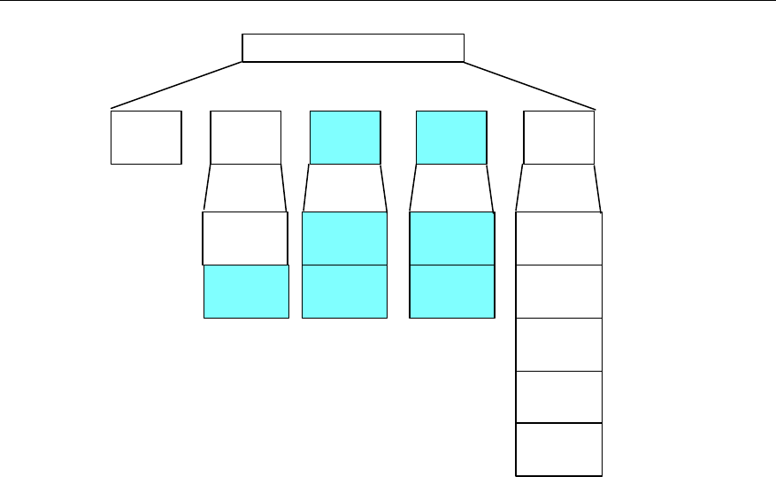
User Manual
Airbridge cBTS3612 CDMA Base Station System Description
4 System Function
4-20
Reverse CDMA channel
R-ACH R-TCH R-EACH R-CCCH
R-SCCH
R-FCH
R-TCH
(RC1~2) (RC3~4)
R-EACH
R-PICH
R-CCCH
R-PICH
R-DCCH
R-PICH
0~7 0~1
R-SCH
R-FCH
0~2
0~1
Subchannel
R-PC
Figure 4-12 Configuration of reverse physical channel
l R-ACH (Reverse Access Channel)
R-ACH is used by MS to originate the communication with BTS, and respond to
paging channel message. MS uses random access protocol to originate access
procedure. Regarding each of the supported paging channel, Maximum 32 access
channels can be supported.
l R-TCH (Reverse Traffic Channel)
R-TCH is used by MS to send the user information and signaling information in the
course of the call.
In the configuration of RC1~RC2, R-TCH can be sub-divided into:
R-FCH (Reverse Fundamental Channel), and
R-SCCH (Reverse Supplemental Code Channel).
In the configuration of RC3~RC4, R-TCH can be sub-divided into:
R-PICH (Reverse Pilot Channel) assisting BTS to capture MS and improve receiving
performance,
R-DCCH (Reverse Common Control Channel) used to bear traffic information and
signaling information,
R-FCH (Reverse Fundamental Channel) used to bear traffic information,
R-SCH (Reverse Supplemental Channel) used to bear the traffic information, and

User Manual
Airbridge cBTS3612 CDMA Base Station System Description
4 System Function
4-21
R-PC subchannel (Reverse Power Control sub-channel), only used to configure
RC3 and RC4. The MS shall supporting inner loop power control and outer loop
power control on this channel.
l R-EACH (Reverse Enhanced Access Channel)
R-EACH is used by MS to originate the communication with BTS, or respond to the
message that is specially sent to MS. R-EACH adopts random access protocol and
supports two types of access modes: Basic Access Mode and Reservation Access
Mode.
l R-CCCH (Reverse Common Control Channel)
R-CCCH is used to send the user and signaling information to BTS in case of not
using reverse traffic channel. Two access modes are supported: Reservation
Access Mode and Designated Access Mode.
&
Notes:
In Figure 4-12, the channel in shadow will be supported in the subsequent version.
For the location and function of the above channels in call procedure, please refer to” 4.2 Call
Procedure”.
4.5.5 Easy Installation and Operation
RF blind mate technology is used in RF part of BTS. During the installation or
maintenance, the user just need to insert the modules into corresponding slots of
the subrack, and the tedious work of cabling is saved. BTS RF system can be
remotely controlled by OMC, transmit power, receiver sensitivity and
receive/transmit frequency can be modified easily. Alarm signal generated in RF part
is reported to OMC. In this way, the operator can control and monitor the operation
of RF part.
4.5.6 Diversity Receiving
BTS supports diversity receiving function, which is realized through two sets of
independent receivers (including antenna, feeder, CDU/DFU, RLDU).
The two receivers demodulate the received signals at the same time, and then the
baseband processing unit decodes the signals with diversity mergence algorithm to
obtain diversity gain. Diversity receiving enhances BTS receivers' capability to resist
attenuation, so that the BTS can achieve satisfactory receiving effect even in
complicated radio transmission conditions.

User Manual
Airbridge cBTS3612 CDMA Base Station System Description
4 System Function
4-22
4.5.7 Cell Breath
BTS can control the transmit power and receive sensitivity so as to adjust the
effective coverage of cells and balance the system load. This feature is especially
important to CDMA system. The control range of transmit power and receive
sensitivity provided by BTS for cell breath is 24dB. The transmit power is regulated
at a step of 0.5dB and receive sensitivity at a step of 1dB.
4.6 Operation and Maintenance
4.6.1 Software Loading
I. Overview
BTS supports remote software loading and local loading from an LMF. The
configuration data of BTS can be loaded to OMU through software loading function.
Software loading procedure consists of two steps: Software is downloaded to BCKM
through OMC/LMF, and then BCKM transfers the software to other boards.
When BTS is powered on and starts operation, the boards will run the existing
software in its Flash Memory. Only when the software is upgraded will download
command be sent through OMC, LMF or FTP tool to activate the software
downloading process.
II. Software loading from OMC to BCKM
In software upgrading, the software is downloaded from OMC to BCKM memory,
and then saved in the Flash Memory of BCKM. BTS configuration data can also be
downloaded to OMU with this function.
III. Software loading from BCKM to other boards
Through OMC or LMF, the downloaded software saved in the Flash Memory of
BCKM can be loaded to any specified board and activated. In this way, software
online upgrading is achieved.
IV. Local/remote software loading from FTP
BTS support local and remote software downloading and activation. If necessary,
user can start an FTP Client application and log on to BTS through LMF or RMF,
download the software to a specific board of BTS and activate the software.

User Manual
Airbridge cBTS3612 CDMA Base Station System Description
4 System Function
4-23
4.6.2 Interface Management
I. Abis interface management
Abis interface management procedure includes the allocation, setup and
management of Abis interface transmission links (including E1/optical link, ATM link
and TCP/IP link). The ATM link setup procedure is first originated through a default
OML PVC. After the IP address is obtained through BOOTP flow, TCP link setup
procedure is activated to complete the setup of OML link. The allocation of PVP,
PVC, TCP/IP links (including signaling channel and traffic channel) are allocated
through Abis interface management procedure, which is a part of BTS configuration.
Setting up signaling channel is to allocate ATM (bearing AAL5 link) transmission
path (i.e. allocate VPI and VCI) and IP address on Abis interface of the signaling
channel, and complete the connection of transmission paths.
Setting up traffic channel is to allocate ATM (bearing AAL2 link) transmission path
(i.e. distributing VPI, VCI) on Abis interface of the traffic channel and switch the
traffic to internal link transmission path to complete the connection of transmission
paths. Actually, AAL2 link is set up and released dynamically.
Disconnection of traffic channel is the disconnection of ATM transmission path on
Abis interface. When BTS configuration changes, Abis configuration can be
changed or this function may be used for maintenance.
II. Air interface management
Main function of the logic part of air interface management is fulfilled by logic
operation & maintenance part. The air interface management involves some O&M
functions related to implementing radio communication, including configuration of
BTS transceiver attributes and channel attributes configuration.
BTS transceiver attributes include parameters such as CSM chip parameter,
physical channel transmit format, sector bypass, sector delay, antenna connection
status, and transmit diversity (OTD) selection. The configuration of BTS transceiver
attributes is activated by OMC through sending configuration message. The result of
the operation is that attributes of the corresponding BTS objects are set to specified
status.
Channel attributes are the driving parameters of the channel element, including
channel type and channel gain. Channel attributes configuration is activated by
OMC through sending configuration message. The result of the operation is that
attributes of the corresponding BTS objects are set to specified status.

User Manual
Airbridge cBTS3612 CDMA Base Station System Description
4 System Function
4-24
4.6.3 Test Management
Test management is an important function of BTS maintenance. When a BTS fault
occurs, test will be conducted to locate the problem. In the process of BTS operation,
it is also necessary to make regular tests to some items so as to monitor the
performance change of BTS.
BTS provides powerful test functions, including:
1) Self-test
Self-test is to check the software and hardware of boards under the control of board
software. During the test, normal service functions may be affected.
l Site self-test: all boards in BTS perform self-test.
l Board self-test: specified boards perform self-test.
2) Loopback test
The control console determines the data and length of loopback. Loopback data are
sent from the control console, forwarded by OMU to the high layer of board software,
and looped back. Then OMU will make judgment whether the data are correct and
return the information to the control console.
4.6.4 Status Management
Board status serves as a base for determing system working status, resource
distribution and fault locating. Board status includes the operational status that
describes the operation condition of the board, availability status, and additional
status that describes active/standby and chip status of the board.
Active/standby status is defined as follows:
Status (active/standby) Description
Active Active board, or there is no standby board
Standby Standby board
Chip status is defined as follows:
Status (chip status) Description
Not mounted Not installed
OK Good
Error Poor
Operational status describes the operation of the board, which is defined as follows:
Status (Operational status) Description
Enabled Permitted
Disabled Prohibited

User Manual
Airbridge cBTS3612 CDMA Base Station System Description
4 System Function
4-25
Availability status is the explanation of the operational status, which is defined as
follows:
Status (availability
status) Description Cause
Failed Operation is abnormal due to serious
fault (alarm message can still be
reported).
Critical alarm occurs.
Power off Operation is abnormal due to interruption
of communication with OMU.
Board is not in position. Board is
initialized. Board communication is
interrupted. The status is usually caused
as OMU can not detect any board.
Offline Operation is abnormal since data are not
configured. .
The status occurs after board
software/hardware are installed but
configuration data is not received.
Blocked Operation is abnormal since block
command is received, operation is
abnormal.
This status occurs after lock command is
received and before unlocked command
is received.
Dependence Operation is abnormal due to fault of
related resource. Other resource failure.
Not installed Operation is abnormal since software or
hardware is not installed.
This status occurs between board
initialization and the sending of
configuration data. In this period, the
software may be downloaded or
activated.
Degraded Fault is not serious, performance is
lowered and the system operates at a low
level.
Minor alarm occurs.
In test In test status, irrelevant to operation
status. Test status.
Status management maintains the consistency of OMC and BTS status, and
provides status query function.
4.6.5 Event Reporting and Processing
Event reporting & processing is very important for BTS operation. Event reporting
means a report is generated when there is error or alarm inside BTS. This may
indicate that a dangerous event has occurred or will occur very soon.
BTS has two types of alarms: board alarm and environment alarm.
I. Board alarm
When an alarm occurs or disappears on a board, the board reports the message to
OMU, which forwards it to OMC in due course. Some measures may be taken as
necessary to clear the alarms. The causes of alarms may include the following ones:
1) Transmission and communication alarm
There are E1 port local/remote OFF alarm and loop interruption alarm.

User Manual
Airbridge cBTS3612 CDMA Base Station System Description
4 System Function
4-26
2) Clock alarm
There are various clock source alarms and phase-locked loop failure alarm.
3) Power alarm
There are over-voltage or under-voltage alarm, and power failure alarm.
4) Other alarms
There are board hardware fault, internal bus alarm and software running error.
After receiving the board alarm message, OMU takes measures according to the
alarm severity. For critical alarm, the board will be resetted or the carrier powered off
immediately to minimize the damage. OMU reports all alarms to OMC, which will be
shown on the graphic user interface of OMC.
II. Environment alarm
BTS internal environment alarms are collected by OMU, and external environment
alarms are collected by an external environment alarm collection box. External
environment alarms include fire, smoke, illegal invasion, soaking, temperature,
humidity and other alarms. After receiving the environment alarm, OMU activates
external devices through the alarm box, such as air-conditioner, fire-distinguisher,
smoke scrubber, dehumidifier or siren. At the same time, OMU reports the alarms to
OMC, which will be displayed on graphic user interface of OMC.
4.6.6 Equipment Management
Equipment management here means general management oriented to physical
objects (hardware). Management and operation of special equipment may also be
involved.
I. General function
1) Operation startup
Equipment operation involves startup procedure and synchronization problem.
Operation startup function serves this purpose, i.e. the equipment should be started
in correct time. OMC sends operation startup command and the result of execution
is the startup and operation of the specified object.
2) Equipment switchover
Important boards are designed with active/standby configuration. When the active
board gets faulty, service can be switched to the standby board automatically or
under control to reduce the loss. In addition, OMC can also send command to make
an object switched. Equipment is be switched over because a fault has occurred or
a switchover command is received from OMC (LMF). The result of the operation is
that the active is switched to the standby and vice versa.

User Manual
Airbridge cBTS3612 CDMA Base Station System Description
4 System Function
4-27
3) Re-initialization
A managed object may need to be re-initialized for some reasons (usually a fault
has occurred to the equipment or a great deal of data need to be re-configured).
Then OMC can directly send commands to make it re-initialized. Hierarchical
initialization function is provided, i.e. part of or all of boards can be reset.
OMC sends re-initialization command. The result of execution is that the specified
object will be re-initialized.
4) Setting site control output
Some additional devices on the site, such as air-conditioner, power switch,
fire-fighting equipment and door control, need additional control paths. This function
is designed for this purpose.
OMC sends site control output command and the result of this function is that the
specified controlled object acts as required.
II. Configuration management for special devices
This function completes the configuration management of some special functional
units of BTS, including clock configuration, BCIM configuration and BRDM
configuration.
1) Configuration of clock parameters
The function of BTS clock module is to provide radio synchronization clock. CDMA
system is a synchronized communication system, which requires strict time
synchronization between base stations. The reference time of the public CDMA
system is GPS time, but the system can also locks and synchronized to UTC
(Universal Coordinated Time). Synchronized with GPS via the local high-precision
thermostatic crystal oscillator, CLK module of the board divides the frequency to get
the internal clock signals.
To ensure normal operation of the clock module, the following data should be
configured:
l Length of antenna & feeder
Delay is compensated according to the length of antenna & feeder and the delay of
the unit length.
l Time zone
Default time zone is Beijing time.
l Time reference
GPS time or UTC time may be used. If GPS time is used, there is no leap second
correction, which means that the second value is 0~59. If UTC is used, there is leap
second correction, i.e. the second value is 0~60. In one network, only one time
reference should be used.

User Manual
Airbridge cBTS3612 CDMA Base Station System Description
4 System Function
4-28
The parameter configuration messages of this function are sent by OMC. The result
of this function is that clock module outputs satisfactory clock signals.
2) BCIM configuration
BCIM configuration includes:
l IMA link group and link configuration.
l Configuration of various ATM links used locally, including Abis signaling link,
OML and traffic link.
l Configuration of trunks of other BTSs when the local BTS is cascaded.
3) BRDM configuration
BRDM configuration includes the connection parameters of BCPM and BTRMs that
are connected with this BRDM, such as port number and timeslot number of BCPM
and BTRM. The purpose is to generate switching network tables and control
parameters of BRDM.
4.6.7 Site Configuration
Site configuration management involves the configuration management of BTS
general structure, including site capacity and connection relation. Main functions
include board configuration, antenna & feeder connection configuration, power
amplifier connection configuration and BTS local cell configuration.
I. BTS hardware configuration
BTS hardware configuration is to add or remove specified physical board for site
configuration.
OMC sends hardware configuration message and the result of execution is that BTS
board is in the specified configuration status.
II. Antenna & feeder connection configuration
BTS antenna & feeder connection configuration is to configure antenna & feeder
connection diagram for BTS, so that BTS can get information about the division of
local cells and some alarm related information when a fault occurs.
OMC sends antenna & feeder connection configuration command. The result of
execution is that BTS configures antenna & feeder connection diagram according to
the command and provides local cell division relation of BTS.
III. BTS local cell configuration
BTS local cell configuration is to provide BTS with information such as distribution
relation of BTS equipment defined by the connection relation, including number of
carriers and number of channel elements can be configured for each carrier.

User Manual
Airbridge cBTS3612 CDMA Base Station System Description
4 System Function
4-29
OMC sends BTS local cell configuration message and the result of execution is that
BTS gets the local cell configuration relation.
4.6.8 Operation Status Tracing
Operation status tracing is an important approach to check when the system is
operating normally.
One function is to trace the high-layer interface messages between OMC and BSC,
between BSC and BTS, and between the functional units of BTS, including:
l Abis O&M message between OMC and OMU.
l O&M message between OMU and other functional units inside BTS.
l Abis signaling between BSC and BCKM.
l Interface message between BCKM and BCPM/BTRM.
l Communication message between active and standby boards.
This function supports the tracing on multiple interfaces from several control
consoles at the same time.
The other function is to trace the board resource information such as CPU
availability and temperature.
4.6.9 Other Functions
I. Version management
It refers to the management and query of software/hardware versions.
II. Fan and power management
Maintenance functions for the internal devices of BTS, such as fan and power
supply, are available.

User Manual
Airbridge cBTS3612 CDMA Base Station System Description
5 System Configuration
5-1
5 System Configuration
This chapter introduces cBTS3612 system configuration, based on which some
typical configuration examples are given. With this chapter, users can get a basic
understanding of cBTS3612 configuration principle.
5.1 Overview
BTS consists of the following parts in physical structure:
l Power distribution box
l Baseband subrack
l Fan subrack
l Power supply subrack
l RF subrack
l RLDU subrack
l CDU/DFU subrack
BTS is designed to accommodate 36 sector-carriers in full configuration, and
supports the combination of 3 cabinets (one basic cabinet and two extended
cabinets). The difference between a basic cabinet and an extended cabinet is that a
basic cabinet needs a baseband subrack and fan subrack The basic cabinet and
extended cabinet are connected with optical fibers.
One cabinet supports as many as 12 sector-carriers. Main configuration modes
include omni cell, 3-sectors and 6-sectors configurations.
5.1.1 Basic/Extended Cabinet Configuration
Configuration of a basic cabinet is as shown in Figure 5-1.
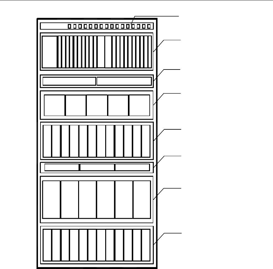
User Manual
Airbridge cBTS3612 CDMA Base Station System Description
5 System Configuration
5-2
0
B
C
I
M
1
B
C
I
M
2
B
C
P
M
3
B
C
P
M
4
B
C
P
M
5
B
C
P
M
6
B
C
P
M
7
B
C
P
M
8
B
R
D
M
B
R
D
M
B
C
K
M
B
C
K
M
B
R
D
M
B
R
D
M
B
C
P
M
B
C
P
M
B
C
P
M
B
C
P
M
B
C
P
M
B
C
P
M
B
R
D
M
B
R
D
M
Fan box 1
Power distribution box
P
S
U
B
H
P
A
B
T
R
M
RLDU
C
D
U
10 11 12 13 14 15 16 17 18 19 20 219
Baseband
subrack
P
S
U
P
S
U
P
S
U
P
S
U
RLDU RLDU
C
D
U
C
D
U
C
D
U
C
D
U
C
D
U
B
H
P
A
B
T
R
M
B
H
P
A
B
T
R
M
B
H
P
A
B
T
R
M
B
H
P
A
B
T
R
M
B
H
P
A
B
T
R
M
B
H
P
A
B
T
R
M
B
H
P
A
B
T
R
M
B
H
P
A
B
T
R
M
B
H
P
A
B
T
R
M
B
H
P
A
B
T
R
M
B
H
P
A
B
T
R
M
Fan box 2
Fan
subrack
PSU
subrack
RF
subrack
RLDU
subrack
CDU/DFU
subrack
RF
subrack
Figure 5-1 Configuration of a basic cabinet
Difference between basic cabinet and extended cabinet: Boards are not necessary
in the baseband subrack of the extended cabinet, and the fans also are not
necessary in fan subrack.
The front view of a basic cabinet is shown in Figure 5-2.
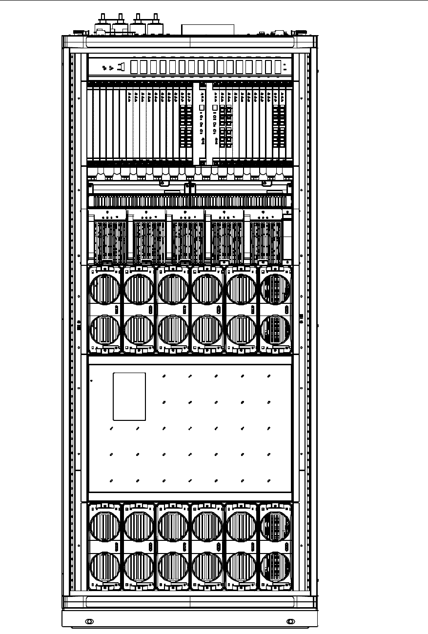
User Manual
Airbridge cBTS3612 CDMA Base Station System Description
5 System Configuration
5-3
Figure 5-2 Front view of a basic cabinet
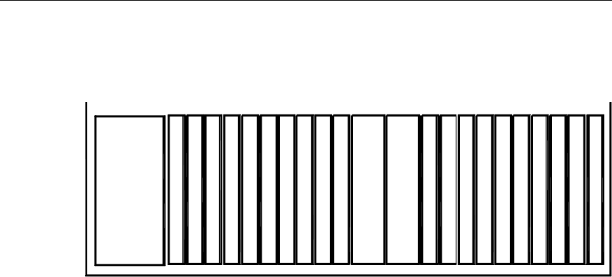
User Manual
Airbridge cBTS3612 CDMA Base Station System Description
5 System Configuration
5-4
5.1.2 Baseband Subrack Configuration
The baseband subrack in full configuration is shown in Figure 5-3.
0
B
C
I
M
1
B
C
I
M
2
B
C
P
M
3
B
C
P
M
4
B
C
P
M
5
B
C
P
M
6
B
C
P
M
7
B
C
P
M
8
B
R
D
M
B
R
D
M
B
C
K
M
B
C
K
M
B
R
D
M
B
R
D
M
B
C
P
M
B
C
P
M
B
C
P
M
B
C
P
M
B
C
P
M
B
C
P
M
B
R
D
M
B
R
D
M
10 11 12 13 14 15 16 17 18 19 20 219
Figure 5-3 The baseband subrack in full configuration
The boards in the baseband subrack include BCIM, BCPM, BRDM, and BCKM. The
boards should be configured according to the following rules
I. BCIM
BCIM provides interface to BSC. BCIM is configured according capacity demand
and service type. 2 BCIMs are needed in full configuration (in this case they can
operation in load sharing mode). Each BCIM boards can support 8 E1 links.
II. BCPM
BCPM board is the channel processing board of BTS. At most 12 BCPMs can be
configured in the baseband subrack. There are two types of BCPMs. The
processing capability of type-A BCPM is 64 reverse channels and 128 forward
channels, while the capability of type-B BCPM is 128 reverse channels and 256
forward channels
BCPMs are configured based on the channel processing capability required by the
system, with consideration of BTRM quantity and board types. Typical configurations
are listed in Table 5-1.
The board Nos. of BCPMs are not successive. The left six are numbered as No.0 to
No.5, while the right six are numbered as No.8 to No.13.
When configuring BCPM, note the difference between the inner half subrack and
outer half subrack. BCPMs No.0, No.1, No.2, No.3, No.12 and No.13 belong to the
outer half subrack, while BCPMs No.4, No.5, No.8, No.9, No.10 and No.11 belong to
the inner half subrack. The BCPMs in different half subracks cannot be configured in
the same CE pool.

User Manual
Airbridge cBTS3612 CDMA Base Station System Description
5 System Configuration
5-5
Table 5-1 Configuration of BCPMs
BTS configuration Number of type-A BCPM Number of type-B BCPM
O1 1 Not recommended
O2 2 Not recommended
S111 2 1
S222 4 2
S333 6 3
S444 8 4
The above configurations are for cdma2000 1X system. For 3-sector configuration,
type-B BCPMs are recommended. For IS95 configuration, the quantity should be
reduced by half.
In normal cases, no redundancy is required. If one board fails, system will
automatically shield the faulty board. In this case, the system capacity decreases,
but the service is maintained.
III. BRDM
There are two types of BRDM boards, namely multi-mode BRDM and single-mode
BRDM. The multi-mode BRDM is used to connect the BTRM in the cabinet, while
the single-mode BRDM is used to cascade the SoftSite (ODU3601C).
Providing 6 pairs of ports for leading out optical fibers, the multi-mode BRDM can be
connected with 6 BTRMs. For full configuration of 36 BTRMs, 6 BRDMs are needed.
In the case BTRMs are less than 6, only 1 BRDM should be configured. For 6-12
BTRMs, 2 BRDMs are needed. The BRDM should be configured from slot No.12
and No.13.
When more than 12 BTRMs are configured, BRDMs are needed in slots No.8, No.9,
No.20 and No.21 to increase the number of optical fiber interfaces, as shown in
Figure 5-3. The configuration principle is that one more BRDM shall be configured
when 6 BTRMs are added.
The single-mode BRDM provides 3 pairs of ports, leading out optical fibers. It can
cascade 3 SoftSites (ODU3601C) in star networking.
IV. BCKM
Normally, one BCKM is enough. For redundancy purpose 2 BCKMs can be used
(working in active/standby mode). BCKM receives GPS signal from outside and
provides 10MHz clock connection tester externally. In addition, it provides some
other interfaces.
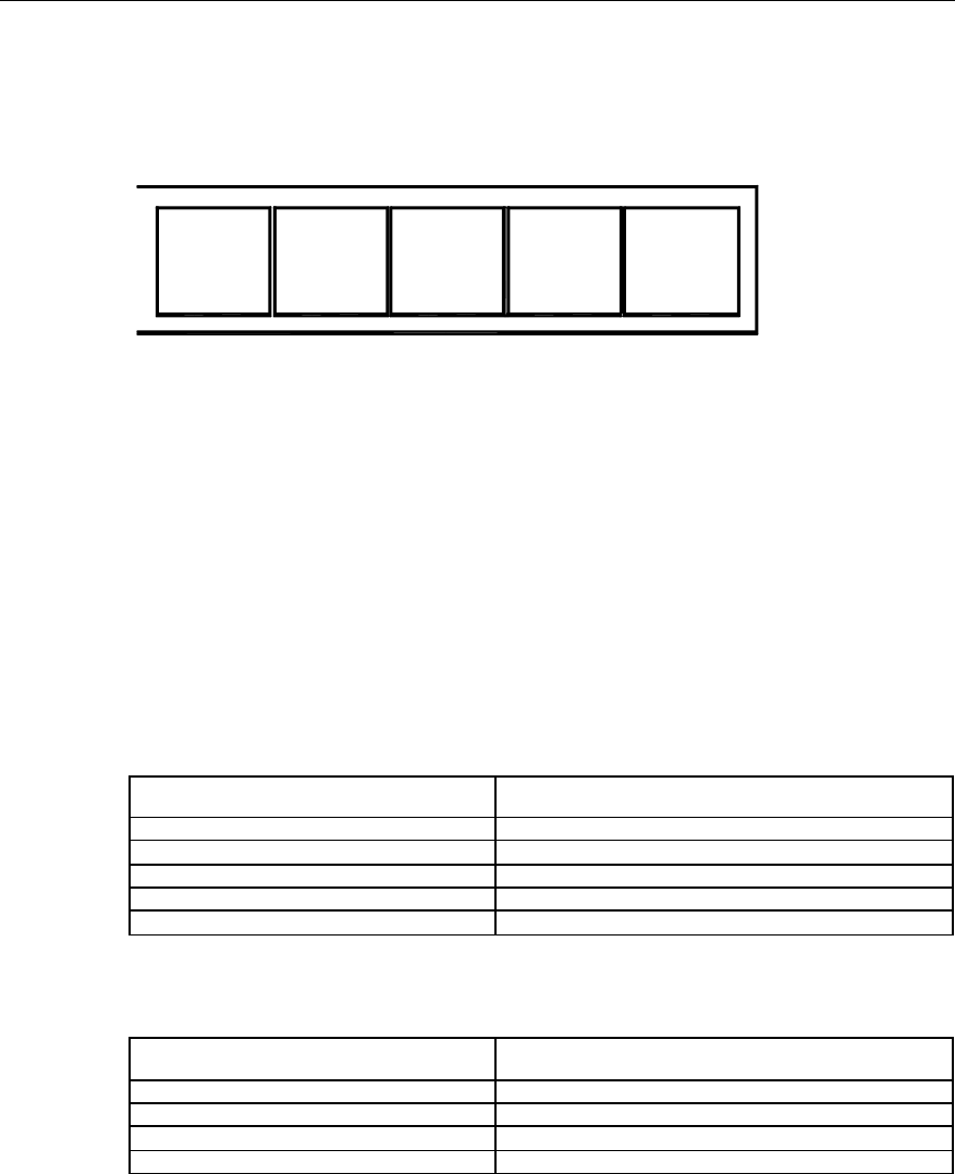
User Manual
Airbridge cBTS3612 CDMA Base Station System Description
5 System Configuration
5-6
5.1.3 Power Supply Subrack Configuration
Power supply module provides +27V power for the whole system, 5 modules in full
configuration, as shown in Figure 5-4.
P
S
U
P
S
U
P
S
U
P
S
U
P
S
U
Figure 5-4 Power supply subrack in full configuration
The power supply modules (4+1 redundancy) can ensure at least 7200W output.
The number of modules used depends on the number of BTRMs.
Two power supply modules (one standby) should be configured when there are no
more than 3 BTRMs. One more power supply module is needed for every 3 new
BTRMs added.
Since current equalization output and centralized powering is used, power supply
modules can be inserted in any slots of the basic cabinet and extended cabinet.
The configuration of power supply modules in a basic cabinet is as follows.
Configuration unit (BTRM) Power supply module quantity unit (PCS)
Basic configuration 1
1~3 1+1
4~6 2+1
7~9 3+1
10~12 4+1
The configuration of power supply modules in an extended cabinet is as follows.
Configuration unit (BTRM) Power supply module quantity unit (PCS)
1~3 1+1
4~6 2+1
7~9 3+1
10~12 4+1
5.1.4 RF Modules Configuration
RF modules in full configuration is shown in Figure 5-5.
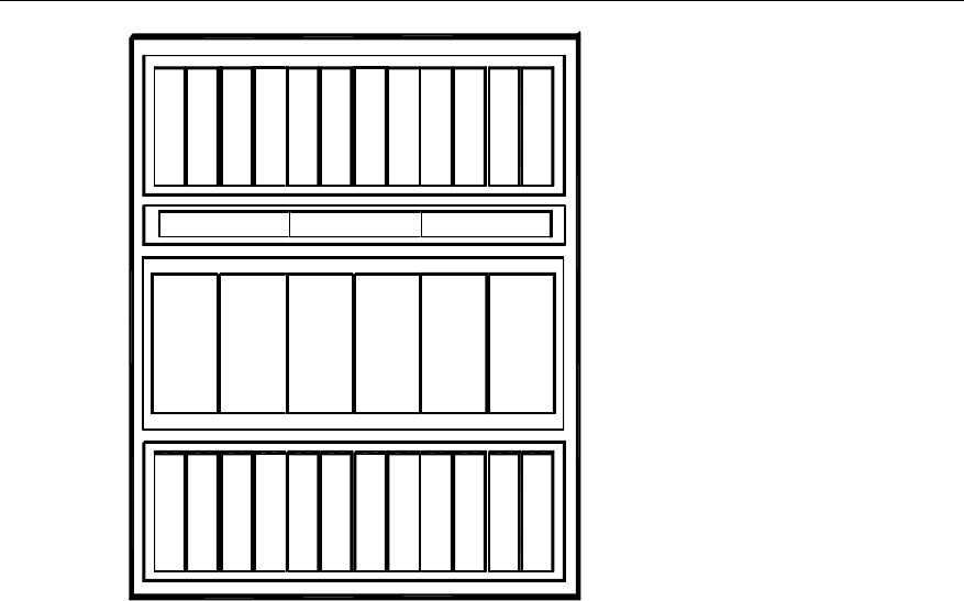
User Manual
Airbridge cBTS3612 CDMA Base Station System Description
5 System Configuration
5-7
B
H
P
A
B
T
R
M
RLDU0
C
D
U
RLDU1 RLDU2
C
D
U
C
D
U
C
D
U
C
D
U
C
D
U
B
H
P
A
B
T
R
M
B
H
P
A
B
T
R
M
B
H
P
A
B
T
R
M
B
H
P
A
B
T
R
M
B
H
P
A
B
T
R
M
B
H
P
A
B
T
R
M
B
H
P
A
B
T
R
M
B
H
P
A
B
T
R
M
B
H
P
A
B
T
R
M
B
H
P
A
B
T
R
M
B
H
P
A
B
T
R
M
012345
1 1 3 3 5 5 7 7 9 9 11 11
0 0 2 2 4 4 6 6 88 10 10
Figure 5-5 RF modules in full configuration (the duplexer in the figure is CDU)
There are 2 RF subracks in BTS, each subrack with 6 BTRM slots and 6 BHPA slots.
Empty slots are covered with dummy panels.
There is one RLDU subrack, configured with 1~3 RLDUs according to actual
implementation.
There is one CDU/DFU/DDU subrack, configured with 1~6 CDUs or DFUs or DDUs
according to needs. Each DFU supports 1 BTRM. Each DDU supports 2 BTRMs
(carrier spacing is not necessary), Each CDU supports 2 BTRMs (the BTRMs
supported by each CDU should be larger than or equal to 2 carrier spacing).
The configuration of RF devices varies with the quantity of BTRMs.
For CDU and DDU, the corresponding BTRMs and BHPAs are configured from
bottom to top and from left to right (as shown in Figure 5-5). For DFU, they are
configured from left to right in the RF subrack under the DFU. Based on the specific
frequency of CDU, actual implementation conditions should also be considered
when configuring the BTRMs and BHPAs, as described in the introduction to typical
configurations.
5.1.5 Configuration of Antenna Parts
Two omni antennae should be used for omni cell.

User Manual
Airbridge cBTS3612 CDMA Base Station System Description
5 System Configuration
5-8
For 3-sectors and 6-sectors configuration, each sector needs one bi-polarization
antenna or two uni-polarization antennae.
For operation at 1900MHz, lightning arrester should be equipped for the antenna
system, while the tower-top amplifier is optional.
5.2 Typical Configurations
The cBTS3612 support 450MHz band, 800MHz band and 1900MHz band, the
typical configurations are listed as below.
I. Typical configuration of cBTS3612 for 450MHz band
l 1 carrier omni cell, i.e. O(1).
l 1 carrier % 3 sectors, i.e. S(1/1/1).
l 2 carriers % 3 sectors, i.e. S(2/2/2).
l 3 carriers % 3 sectors, i.e. S(3/3/3).
II. Typical configuration of cBTS3612 for 800MHz band
l 2 carriers omni cell, i.e. O(2).
l 1 carrier % 3 sectors, i.e. S(1/1/1).
l 4 carriers % 3 sectors, i.e. S(4/4/4).
l 2 carriers % 6 sectors, i.e. S(2/2/2/2/2/2).
5.2.1 Typical Configuration of cBTS3612 for 450MHz Band
The duplex supported currently in this band is CDU and DFU.
I. O(1) Configuration
The configuration of cBTS3612 for O(1) includes:
l 1 BCIM, 1 BRDM, 1-2 BCKMs, and BCPM can be configured according to
actual requirement.
l 2 power supply modules.
l 2 unipolarized omni antennas.
l The configuration of the RF modules is shown in Figure 5-6.
l Logic connection of RF modules is shown in Figure 5-7.
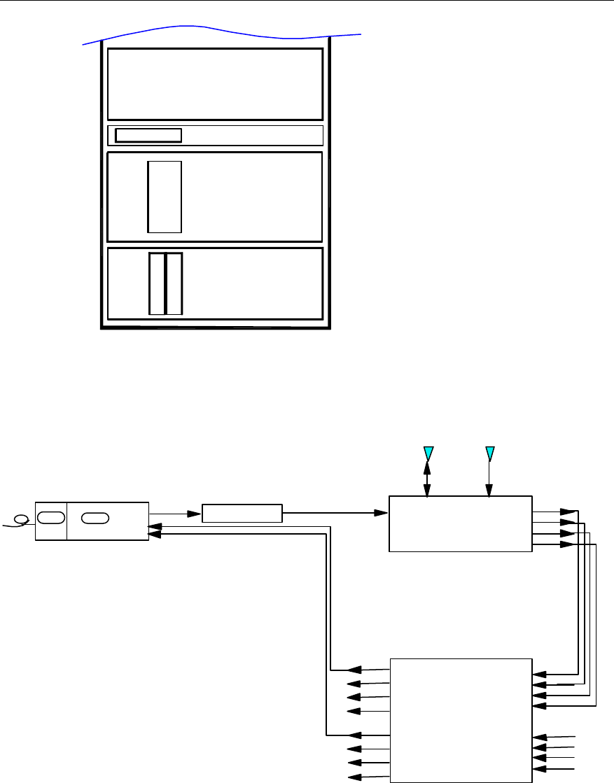
User Manual
Airbridge cBTS3612 CDMA Base Station System Description
5 System Configuration
5-9
D
F
U
RLDU
B
H
P
A
B
T
R
M
Figure 5-6 O(1) RF configuration
BHPA
PA_IN PA_OUT TX_IN
Main_ ANT Div._ ANT
Main_RX_OUT
Div._RX_OUT
FWDCPL_OUT
REVCPL_OUT
DFU
A_Main_RX_IN
A_Div._RX_IN
A_FWDCPL_IN
A_REVCPL_IN
B_Main_RX_IN
B_Div._RX_IN
B_FWDCPL_IN
B_REVCPL_IN
A_Rm1
A_Rm2
A_Rm3/B_Rm1
A_Rm4/B_Rm2
A_Rd1
A_Rd2
A_Rd3/B_Rd1
A_Rd4/B_Rd2
RLDU
Mode("1")
BTRM
TX_RFm
RX_RFm
RX_RFd
BRCMBIFM TX_RFd
Figure 5-7 Logic connection of RF modules for O(1) configuration
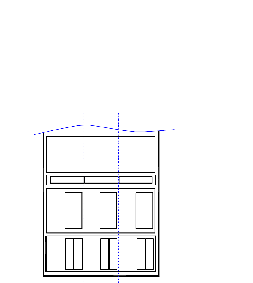
User Manual
Airbridge cBTS3612 CDMA Base Station System Description
5 System Configuration
5-10
II. S(1/1/1) Configuration
The following is the configuration of cBTS3612 for Type S(1/1/1) (i.e: 1 carrier x 3
sectors):
l 1 BCIM, 1 BRDM, 1-2 BCKMs, and BCPM can be configured according to
actual requirement.
l 2 power supply modules.
l 2 unipolarization directional antennas or 1 bipolarization directional antenna for
each sector.
l The configuration of the RF modules is shown in Figure 5-8.
l Logic connection of RF modules of one-sector is shown in Figure 5-7.
D
F
U
B
H
P
A
B
T
R
M
RLDU
D
F
U
D
F
U
B
H
P
A
B
T
R
M
B
H
P
A
B
T
R
M
RLDU RLDU
sector0 sector2sector1
Figure 5-8 S(1/1/1) RF configuration
III. S(2/2/2) Configuration
The following is the configuration of cBTS3612 for Type S(2/2/2) (i.e.: 2 carriers x 3
sectors):
l 1 BCIM, 1 BRDM, 1-2 BCKMs, and BCPM can be configured according to
actual requirement.
l 3 power supply modules.
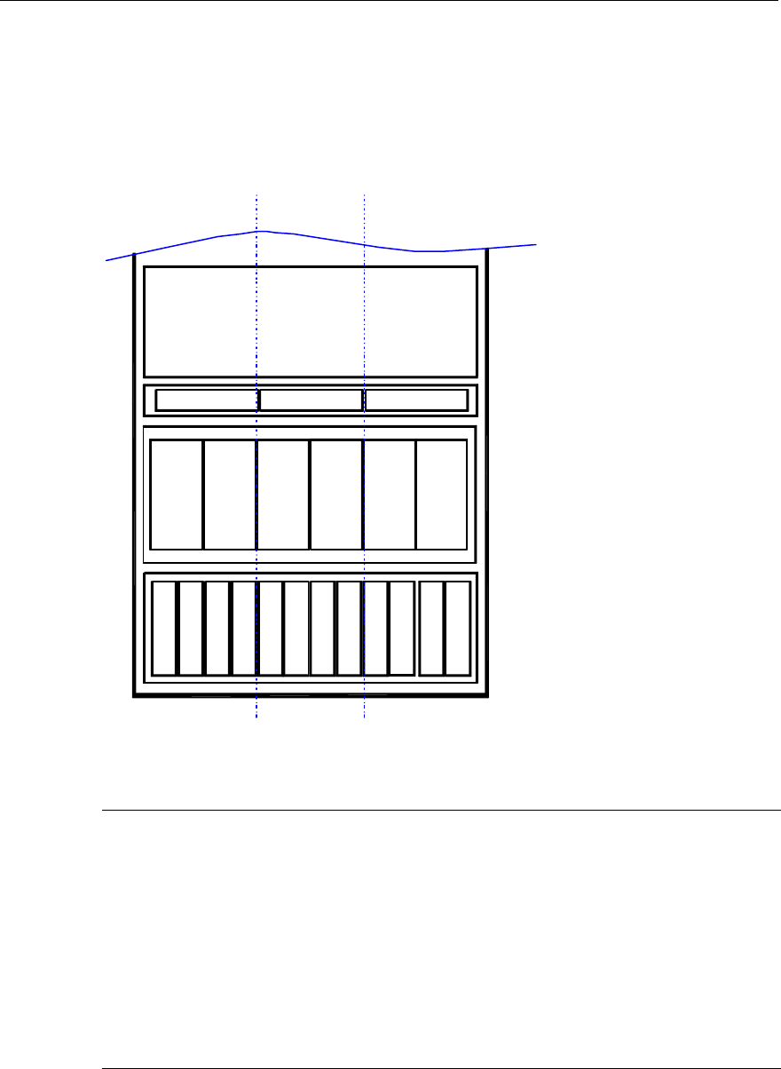
User Manual
Airbridge cBTS3612 CDMA Base Station System Description
5 System Configuration
5-11
l 2 unipolarization directional antennas or 1 bipolarization directional antenna for
each sector.
l The configuration of the RF modules is shown in Figure 5-9.
l Logic connection of RF modules of one-sector is shown in Figure 5-10.
C
D
U
RLDU
C
D
U
C
D
U
RLDU RLDU
B
H
P
A
B
T
R
M
B
H
P
A
B
T
R
M
B
H
P
A
B
T
R
M
B
H
P
A
B
T
R
M
B
H
P
A
B
T
R
M
B
H
P
A
B
T
R
M
sector0 sector2sector1
D
F
U
D
F
U
D
F
U
Figure 5-9 S(2/2/2) RF configuration
&
Note:
The CDU frequency is not adjustable. The carrier channel number of its upper corresponding subrack
is higher and the carrier channel number of its lower corresponding subrack is lower. In the actual
configuration, the specific carrier module slot should be determined by the specific CDU channel
numbers.
For example: When the 160&260-combining CDU is adopted, if the channel number assigned to this
CDU is only 260, the carrier module should be configured in the upper subrack. If the channel number
assigned to this CDU is only 160, the carrier module should be configured in the low er subrack.
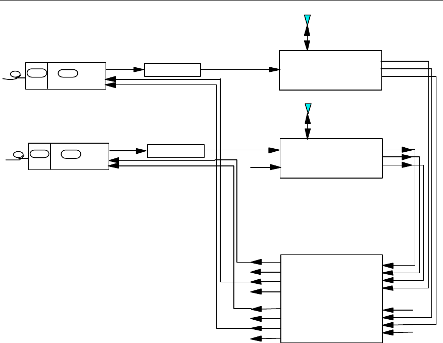
User Manual
Airbridge cBTS3612 CDMA Base Station System Description
5 System Configuration
5-12
TX1_IN
TX2_IN
ANT Main_RX_OUT
FWDCPL_OUT
REVCPL_OUT
CDU
A_Main_RX_IN
A_Div._RX_IN
A_FWDCPL_IN
A_REVCPL_IN
B_Main_RX_IN
B_Div._RX_IN
B_FWDCPL_IN
B_REVCPL_IN
A_Rm1
A_Rm2
A_Rm3/B_Rm1
A_Rm4/B_Rm2
A_Rd1
A_Rd2
A_Rd3/B_Rd1
A_Rd4/B_Rd2
RLDU
Mode("0")
PA_IN PA_OUT
BHPA
BTRM
TX_RFm
RX_RFm
RX_RFd
BRCM
BIFM TX_RFd
TX
Main_ ANT Div._ ANT
Main_RX_OUT
Div._RX_OUT
FWDCPL_OUT
REVCPL_OUT
DFU
BTRM
TX_RFm
RX_RFm
RX_RFd
BRCM
BIFM TX_RFd PA_IN PA_OUT
BHPA
Figure 5-10 Logic connection of one-sector RF modules for S(2/2/2) configuration
IV. S(3/3/3) Configuration
The following is the configuration of Type S(3/3/3) (i.e.: 3 carriers x 3 sectors):
l 1 BCIM, 2 BRDMs, 1-2 BCKMs, and BCPM can be configured according to
actual requirement.
l 4 power supply modules.
l 2 unipolarization directional antennas or 1 bipolarization directional antenna for
each sector.
l The configuration of the RF modules is shown in Figure 5-11.
l Logic connection of RF modules for one-sector is shown in Figure 5-12
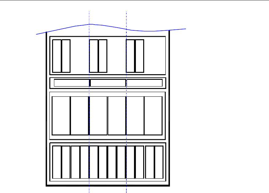
User Manual
Airbridge cBTS3612 CDMA Base Station System Description
5 System Configuration
5-13
C
D
U
B
H
P
A
B
T
R
M
RLDU
C
D
U
C
D
U
B
H
P
A
B
T
R
M
B
H
P
A
B
T
R
M
RLDU RLDU
B
H
P
A
B
T
R
M
B
H
P
A
B
T
R
M
B
H
P
A
B
T
R
M
B
H
P
A
B
T
R
M
B
H
P
A
B
T
R
M
B
H
P
A
B
T
R
M
sector0 sector2sector1
D
F
U
D
F
U
D
F
U
Figure 5-11 S(3/3/3) RF configuration
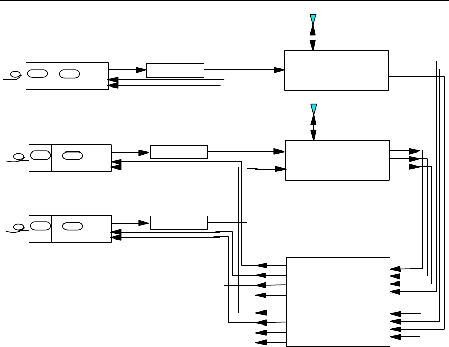
User Manual
Airbridge cBTS3612 CDMA Base Station System Description
5 System Configuration
5-14
TX1_IN
TX2_IN
ANT Main_RX_OUT
FWDCPL_OUT
REVCPL_OUT
CDU
A_Main_RX_IN
A_Div._RX_IN
A_FWDCPL_IN
A_REVCPL_IN
B_Main_RX_IN
B_Div._RX_IN
B_FWDCPL_IN
B_REVCPL_IN
A_Rm1
A_Rm2
A_Rm3/B_Rm1
A_Rm4/B_Rm2
A_Rd1
A_Rd2
A_Rd3/B_Rd1
A_Rd4/B_Rd2
RLDU
Mode("0")
PA_IN PA_OUT
BHPA
PA_IN PA_OUT
BHPA
BTRM
TX_RFm
RX_RFm
RX_RFd
BRCM
BIFM TX_RFd
BTRM
TX_RFm
RX_RFm
RX_RFd
BRCM
BIFM TX_RFd
TX
Main_ ANT Div._ ANT
Main_RX_OUT
Div._RX_OUT
FWDCPL_OUT
REVCPL_OUT
DFU
BTRM
TX_RFm
RX_RFm
RX_RFd
BRCM
BIFM TX_RFd PA_IN PA_OUT
BHPA
Figure 5-12 Logic connection of one-sector RF modules for S(3/3/3) configuration
5.2.2 Typical Configuration of cBTS3612 for 800MHz Band
The duplex supported currently in this band is CDU.
I. O(2) Configuration
The configuration of cBTS3612 for O(2) includes:
l 1 BCIM, 1 BRDM, 1-2 BCKMs, and BCPM can be configured according to
actual requirement.
l 2 power supply modules.
l 2 unipolarized omni antennas.
l The configuration of the RF modules is shown in Figure 5-13.
l Logic connection of RF modules is shown in Figure 5-14.
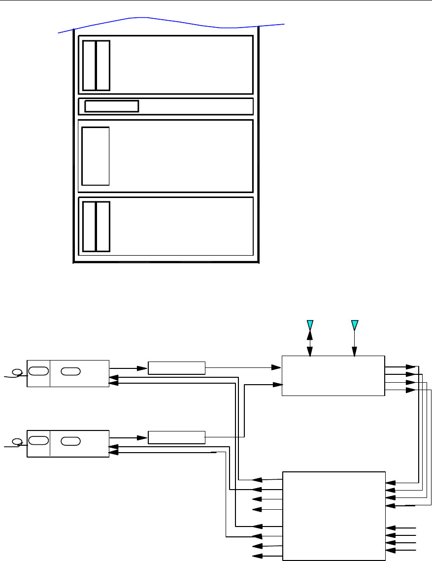
User Manual
Airbridge cBTS3612 CDMA Base Station System Description
5 System Configuration
5-15
C
D
U
B
H
P
A
B
T
R
M
RLDU
B
H
P
A
B
T
R
M
Figure 5-13 O(2) RF configuration
TX1_IN
TX2_IN
Main_ ANT Div._ ANT
Main_RX_OUT
Div._RX_OUT
FWDCPL_OUT
REVCPL_OUT
CDU
A_Main_RX_IN
A_Div._RX_IN
A_FWDCPL_IN
A_REVCPL_IN
B_Main_RX_IN
B_Div._RX_IN
B_FWDCPL_IN
B_REVCPL_IN
A_Rm1
A_Rm2
A_Rm3/B_Rm1
A_Rm4/B_Rm2
A_Rd1
A_Rd2
A_Rd3/B_Rd1
A_Rd4/B_Rd2
RLDU
Mode("1")
PA_IN PA_OUT
BHPA
PA_IN PA_OUT
BHPA
BTRM
TX_RFm
RX_RFm
RX_RFd
BRCM
BIFM TX_RFd
BTRM
TX_RFm
RX_RFm
RX_RFd
BRCM
BIFM TX_RFd
Figure 5-14 Logic connection of RF modules for O(2) configuration
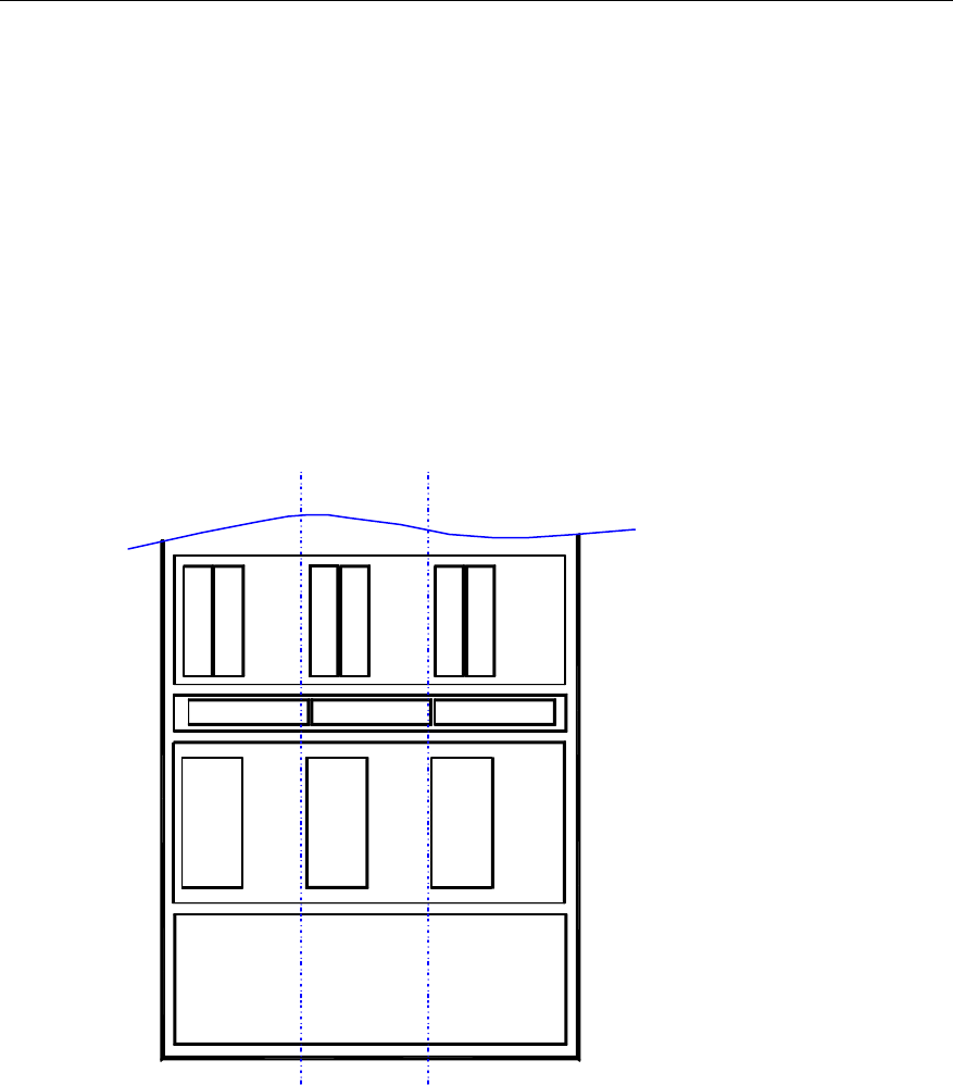
User Manual
Airbridge cBTS3612 CDMA Base Station System Description
5 System Configuration
5-16
II. S(1/1/1) Configuration
The following is the configuration of cBTS3612 for Type S(1/1/1) (i.e.: 1 carrier x 3
sectors):
l 1 BCIM, 1 BRDM, 1-2 BCKMs, and BCPM can be configured according to
actual requirement.
l 2 power supply modules.
l 2 unipolarization directional antennas or 1 bipolarization directional antenna for
each sector.
l The configuration of the RF modules is shown in Figure 5-15.
l Logic connection of RF modules of one-sector is shown in Figure 5-16.
C
D
U
B
H
P
A
B
T
R
M
RLDU
C
D
U
C
D
U
B
H
P
A
B
T
R
M
B
H
P
A
B
T
R
M
RLDU RLDU
sector0 sector2sector1
Figure 5-15 S(1/1/1) RF configuration
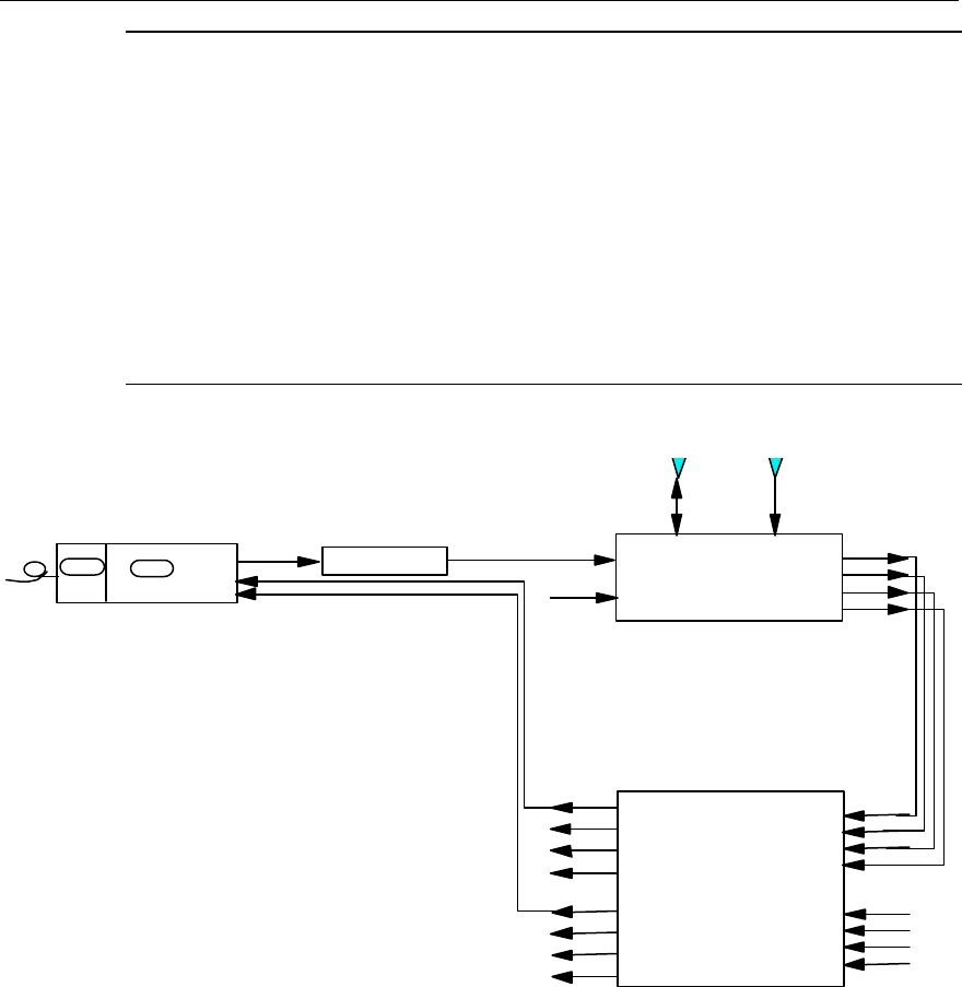
User Manual
Airbridge cBTS3612 CDMA Base Station System Description
5 System Configuration
5-17
&
Note:
The CDU frequency is not adjustable. The carrier channel number of its upper corresponding subrack
is higher and the carrier channel number of its lower corresponding subrack is lower. In the actual
configuration, the specific carrier module slot should be determined by the specific CDU channel
numbers.
For example: When the 201&283-combining CDU is adopted, if the channel number assigned to this
CDU is only 283, the carrier modules configured for O(1), S(1/1/1) and S(1/1/1/1/1/1) should be in the
upper subrack. If the channel number assigned to this CDU is only 201, these modules should be
installed in the lower subrack.
BHPA
PA_IN PA_OUT TX1_IN
TX2_IN
Main_ ANT Div._ ANT
Main_RX_OUT
Div._RX_OUT
FWDCPL_OUT
REVCPL_OUT
CDU
A_Main_RX_IN
A_Div._RX_IN
A_FWDCPL_IN
A_REVCPL_IN
B_Main_RX_IN
B_Div._RX_IN
B_FWDCPL_IN
B_REVCPL_IN
A_Rm1
A_Rm2
A_Rm3/B_Rm1
A_Rm4/B_Rm2
A_Rd1
A_Rd2
A_Rd3/B_Rd1
A_Rd4/B_Rd2
RLDU
Mode("1")
BTRM
TX_RFm
RX_RFm
RX_RFd
BRCM
BIFM TX_RFd
Figure 5-16 Logic connection of one-sector RF modules for S(1/1/1) configuration
III. S(4/4/4) Configuration
The following is the configuration of cBTS3612 for Type S(4/4/4) (i.e.: 4 carriers x 3
sectors):
l 1 BCIM, 2 BRDMs, 1-2 BCKMs, and BCPM can be configured according to
actual requirement.
l 5 power supply modules.
l 2 unipolarization directional antennas or 1 bipolarization directional antenna for
each sector.
l The configuration of the RF modules is shown in Figure 5-17.
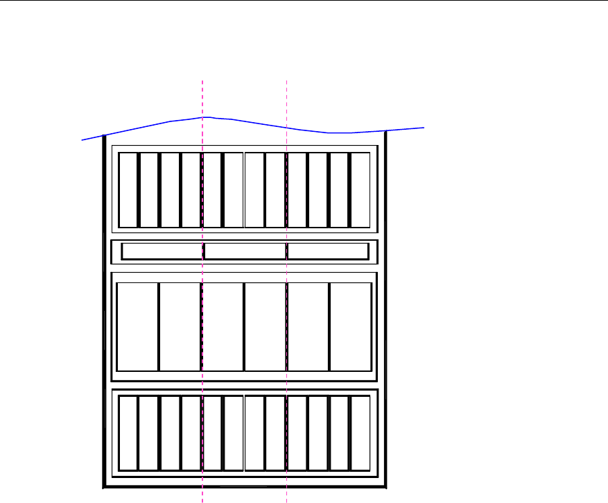
User Manual
Airbridge cBTS3612 CDMA Base Station System Description
5 System Configuration
5-18
l Logic connection of RF modules of one-sector is shown in Figure 5-18.
B
H
P
A
B
T
R
M
RLDU
C
D
U
RLDU RLDU
C
D
U
C
D
U
C
D
U
C
D
U
C
D
U
B
H
P
A
B
T
R
M
B
H
P
A
B
T
R
M
B
H
P
A
B
T
R
M
B
H
P
A
B
T
R
M
B
H
P
A
B
T
R
M
B
H
P
A
B
T
R
M
B
H
P
A
B
T
R
M
B
H
P
A
B
T
R
M
B
H
P
A
B
T
R
M
B
H
P
A
B
T
R
M
B
H
P
A
B
T
R
M
sector0 sector2sector1
Figure 5-17 S(4/4/4) RF configuration
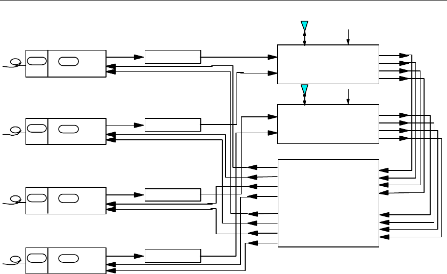
User Manual
Airbridge cBTS3612 CDMA Base Station System Description
5 System Configuration
5-19
TX1_IN
TX2_IN
Main_ ANT Div._ ANT
Main_RX_OUT
Div._RX_OUT
FWDCPL_OUT
REVCPL_OUT
CDU
A_Main_RX_IN
A_Div._RX_IN
A_FWDCPL_IN
A_REVCPL_IN
B_Main_RX_IN
B_Div._RX_IN
B_FWDCPL_IN
B_REVCPL_IN
A_Rm1
A_Rm2
A_Rm3/B_Rm1
A_Rm4/B_Rm2
A_Rd1
A_Rd2
A_Rd3/B_Rd1
A_Rd4/B_Rd2
RLDU
Mode("0")
TX1_IN
TX2_IN
Main_ ANT Div._ ANT
Main_RX_OUT
Div._RX_OUT
FWDCPL_OUT
REVCPL_OUT
CDU
BHPA
PA_IN PA_OUT
BHPA
PA_IN PA_OUT
BHPA
PA_IN PA_OUT
BHPA
PA_IN PA_OUT
BTRM
TX_RFm
RX_RFm
RX_RFd
BRCM
BIFM TX_RFd
BTRM
TX_RFm
RX_RFm
RX_RFd
BRCM
BIFM TX_RFd
BTRM
TX_RFm
RX_RFm
RX_RFd
BRCM
BIFM TX_RFd
BTRM
TX_RFm
RX_RFm
RX_RFd
BRCM
BIFM TX_RFd
Figure 5-18 Logic connection of one-sector RF modules for S(4/4/4) configuration
IV. S(2/2/2/2/2/2) Configuration
The following is the configuration of Type S(2/2/2/2/2/2) (i.e.: 2 carriers x 6 sectors):
l 1 BCIM, 2 BRDMs, 1-2 BCKMs, and BCPM can be configured according to
actual requirement.
l 5 power supply modules.
l 2 unipolarization directional antennas or 1 bipolarization directional antenna for
each sector.
l The configuration of the RF modules is shown in Figure 5-19.
l Logic connection of RF modules of two-sector is shown in Figure 5-20.
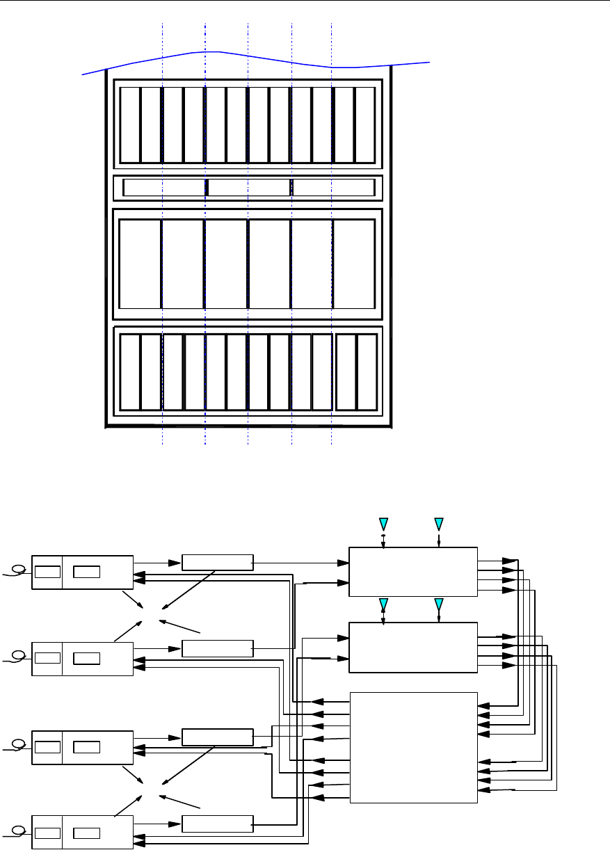
User Manual
Airbridge cBTS3612 CDMA Base Station System Description
5 System Configuration
5-20
C
D
U
B
H
P
A
B
T
R
M
RLDU
C
D
U
C
D
U
B
H
P
A
B
T
R
M
B
H
P
A
B
T
R
M
RLDU RLDU
B
H
P
A
B
T
R
M
B
H
P
A
B
T
R
M
B
H
P
A
B
T
R
M
B
H
P
A
B
T
R
M
B
H
P
A
B
T
R
M
B
H
P
A
B
T
R
M
sector2 sector5sector3
C
D
U
C
D
U
C
D
U
B
H
P
A
B
T
R
M
B
H
P
A
B
T
R
M
B
H
P
A
B
T
R
M
sector1 sector4sector0
Figure 5-19 S(2/2/2/2/2/2) RF configuration
TX1_IN
TX2_IN
Main_ ANT Div._ ANT
Main_RX_OUT
Div._RX_OUT
FWDCPL_OUT
REVCPL_OUT
CDU
A_Main_RX_IN
A_Div._RX_IN
A_FWDCPL_IN
A_REVCPL_IN
B_Main_RX_IN
B_Div._RX_IN
B_FWDCPL_IN
B_REVCPL_IN
A_Rm1
A_Rm2
A_Rm3/B_Rm1
A_Rm4/B_Rm2
A_Rd1
A_Rd2
A_Rd3/B_Rd1
A_Rd4/B_Rd2
RLDU
Mode("1")
TX1_IN
TX2_IN
Main_ ANT Div._ ANT
Main_RX_OUT
Div._RX_OUT
FWDCPL_OUT
REVCPL_OUT
CDU
Sector0
antenna
Sector0
BHPA
PA_IN PA_OUT
TX_RFm
RX_RFm
RX_RFd
TX_RFd
BTRM
BRCMBIFM
BHPA
PA_IN PA_OUTTX_RFm
RX_RFm
RX_RFd
TX_RFd
BTRM
BRCM
BIFM
Sector1
BHPA
PA_IN PA_OUTTX_RFm
RX_RFm
RX_RFd
TX_RFd
BTRM
BRCMBIFM
BHPA
PA_IN PA_OUTTX_RFm
RX_RFm
RX_RFd
TX_RFd
BTRM
BRCMBIFM
Sector1
antenna
Figure 5-20 Logic connection of two-sector RF modules for S(2/2/2/2/2/2) configuration
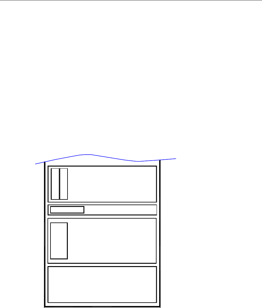
User Manual
Airbridge cBTS3612 CDMA Base Station System Description
5 System Configuration
5-21
5.2.3 Typical Configuration of cBTS3612 in 1900MHz Band
The duplex supported currently in this band is DDU, and it is expected that CDU be
supported also in the future with reference to 1900MHz band planning.
I. O(1) Configuration
The configuration of cBTS3612 for O(1) includes:
l 1 BCIM, 1 BRDM, 1-2 BCKMs, and BCPM can be configured according to
actual requirement.
l 2 power supply modules.
l 2 unipolarized omni antennas.
l The configuration of the RF modules is shown in Figure 5-21.
l Logic connection of RF modules is shown in Figure 5-22.
D
D
U
RLDU
B
H
P
A
B
T
R
M
Figure 5-21 O(1) RF configuration
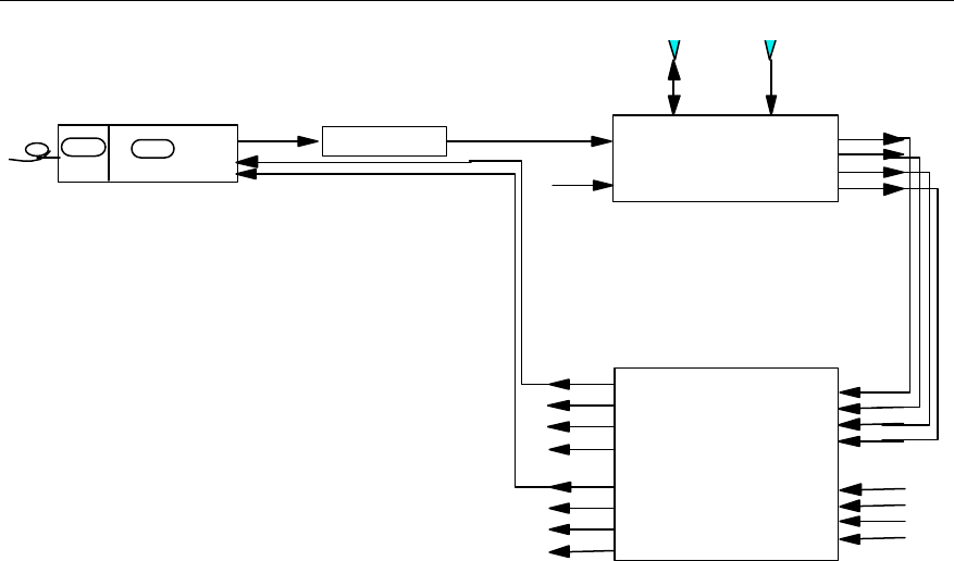
User Manual
Airbridge cBTS3612 CDMA Base Station System Description
5 System Configuration
5-22
BHPA
PA_IN PA_OUT TX1_IN
Main_ ANT Div._ ANT
Main_RX_OUT
Div._RX_OUT
FWDCPL_OUT
REVCPL_OUT
DDU
A_Main_RX_IN
A_Div._RX_IN
A_FWDCPL_IN
A_REVCPL_IN
B_Main_RX_IN
B_Div._RX_IN
B_FWDCPL_IN
B_REVCPL_IN
A_Rm1
A_Rm2
A_Rm3/B_Rm1
A_Rm4/B_Rm2
A_Rd1
A_Rd2
A_Rd3/B_Rd1
A_Rd4/B_Rd2
RLDU
Mode("1")
BTRM
TX_RFm
RX_RFm
RX_RFd
BRCM
BIFM TX_RFd
TX2_IN
Figure 5-22 Logic connection of RF modules for O(1) configuration
II. S(1/1/1) Configuration
The following is the configuration of cBTS3612 for Type S(1/1/1) (i.e.: 1 carrier x 3
sectors):
l 1 BCIM, 1 BRDM, 1-2 BCKMs, and BCPM can be configured according to
actual requirement.
l 2 power supply modules.
l 2 unipolarization directional antennas or 1 bipolarization directional antenna for
each sector.
l The configuration of the RF modules is shown in Figure 5-23.
l Logic connection of RF modules of one-sector is shown in Figure 5-22.
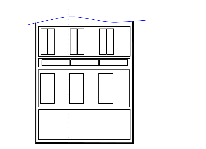
User Manual
Airbridge cBTS3612 CDMA Base Station System Description
5 System Configuration
5-23
D
D
U
B
H
P
A
B
T
R
M
RLDU
D
D
U
D
D
U
B
H
P
A
B
T
R
M
B
H
P
A
B
T
R
M
RLDU RLDU
sector0 sector2sector1
Figure 5-23 S(1/1/1) RF configuration
III. S(2/2/2) Configuration
The following is the configuration of cBTS3612 for Type S(2/2/2) (i.e.: 2 carriers x 3
sectors):
l 1 BCIM, 1 BRDM, 1-2 BCKMs, and BCPM can be configured according to
actual requirement.
l 3 power supply modules.
l 2 unipolarization directional antennas or 1 bipolarization directional antenna for
each sector.
l The configuration of the RF modules is shown in Figure 5-24.
l Logic connection of RF modules of one-sector is shown in Figure 5-25.
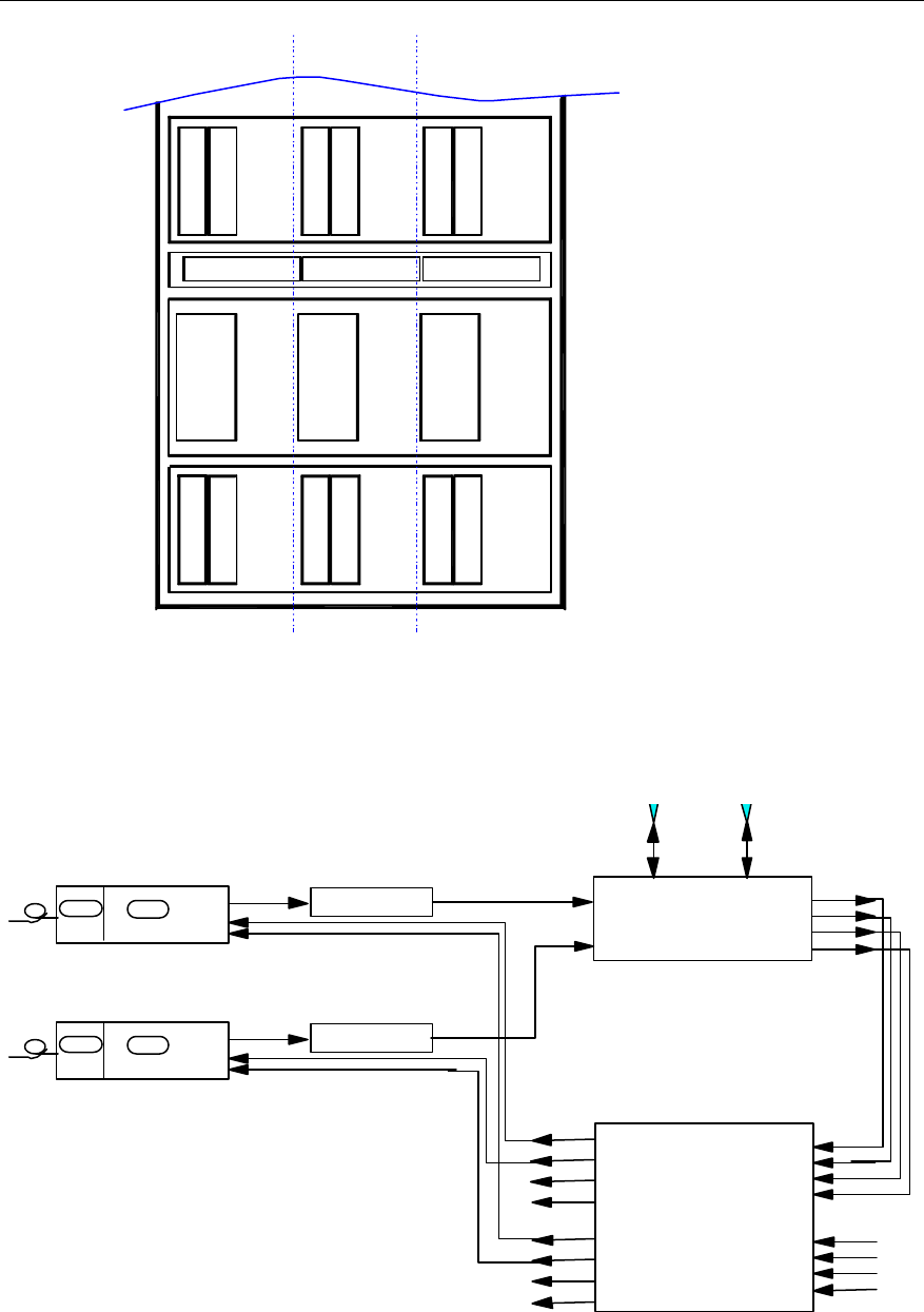
User Manual
Airbridge cBTS3612 CDMA Base Station System Description
5 System Configuration
5-24
D
D
U
B
H
P
A
B
T
R
M
RLDU
D
D
U
D
D
U
B
H
P
A
B
T
R
M
B
H
P
A
B
T
R
M
RLDU RLDU
sector0 sector2sector1
B
H
P
A
B
T
R
M
B
H
P
A
B
T
R
M
B
H
P
A
B
T
R
M
Figure 5-24 S(2/2/2) RF configuration
BHPA
PA_IN PA_OUT TX1_IN
Main_ ANT Div._ ANT
Main_RX_OUT
Div._RX_OUT
FWDCPL_OUT
REVCPL_OUT
DDU
A_Main_RX_IN
A_Div._RX_IN
A_FWDCPL_IN
A_REVCPL_IN
B_Main_RX_IN
B_Div._RX_IN
B_FWDCPL_IN
B_REVCPL_IN
A_Rm1
A_Rm2
A_Rm3/B_Rm1
A_Rm4/B_Rm2
A_Rd1
A_Rd2
A_Rd3/B_Rd1
A_Rd4/B_Rd2
RLDU
Mode("1")
BTRM
TX_RFm
RX_RFm
RX_RFd
BRCM
BIFM TX_RFd
TX2_IN
BHPA
PA_IN PA_OUT
BTRM
TX_RFm
RX_RFm
RX_RFd
BRCM
BIFM TX_RFd
Figure 5-25 Logic connection of one-sector RF modules for S(2/2/2) configuration
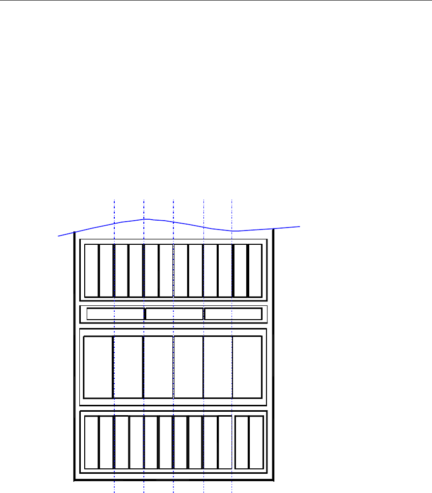
User Manual
Airbridge cBTS3612 CDMA Base Station System Description
5 System Configuration
5-25
IV. S(2/2/2/2/2/2) Configuration
The following is the configuration of Type S(2/2/2/2/2/2) (i.e.: 2 carriers x 6 sectors):
l 1 BCIM, 2 BRDMs, 1-2 BCKMs, and BCPM can be configured according to
actual requirement.
l 5 power supply modules.
l 2 unipolarization directional antennas or 1 bipolarization directional antenna for
each sector.
l The configuration of the RF modules is shown in Figure 5-26.
l Logic connection of RF modules of two-sector is shown in Figure 5-27.
D
D
U
B
H
P
A
B
T
R
M
RLDU
D
D
U
D
D
U
B
H
P
A
B
T
R
M
B
H
P
A
B
T
R
M
RLDU RLDU
B
H
P
A
B
T
R
M
B
H
P
A
B
T
R
M
B
H
P
A
B
T
R
M
B
H
P
A
B
T
R
M
B
H
P
A
B
T
R
M
B
H
P
A
B
T
R
M
sector2 sector5sector3
D
D
U
D
D
U
D
D
U
B
H
P
A
B
T
R
M
B
H
P
A
B
T
R
M
B
H
P
A
B
T
R
M
sector1 sector4sector0
Figure 5-26 S(2/2/2/2/2/2) RF configuration
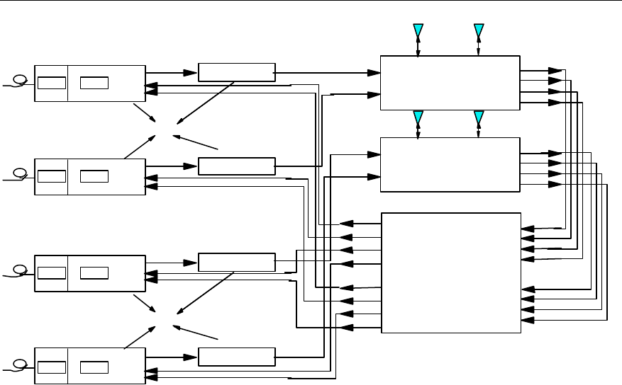
User Manual
Airbridge cBTS3612 CDMA Base Station System Description
5 System Configuration
5-26
TX1_IN
TX2_IN
Main_ ANT Div._ ANT
Main_RX_OUT
Div._RX_OUT
FWDCPL_OUT
REVCPL_OUT
DDU
A_Main_RX_IN
A_Div._RX_IN
A_FWDCPL_IN
A_REVCPL_IN
B_Main_RX_IN
B_Div._RX_IN
B_FWDCPL_IN
B_REVCPL_IN
A_Rm1
A_Rm2
A_Rm3/B_Rm1
A_Rm4/B_Rm2
A_Rd1
A_Rd2
A_Rd3/B_Rd1
A_Rd4/B_Rd2
RLDU
Mode("1")
TX1_IN
TX2_IN
Main_ ANT Div._ ANT
Main_RX_OUT
Div._RX_OUT
FWDCPL_OUT
REVCPL_OUT
DDU
Sector0
antenna
Sector0
BHPA
PA_IN PA_OUT
TX_RFm
RX_RFm
RX_RFd
TX_RFd
BTRM
BRCMBIFM
BHPA
PA_IN PA_OUTTX_RFm
RX_RFm
RX_RFd
TX_RFd
BTRM
BRCM
BIFM
Sector1
BHPA
PA_IN PA_OUTTX_RFm
RX_RFm
RX_RFd
TX_RFd
BTRM
BRCMBIFM
BHPA
PA_IN PA_OUT
TX_RFm
RX_RFm
RX_RFd
TX_RFd
BTRM
BRCMBIFM
Sector1
antenna
Figure 5-27 Logic connection of two-sector RF modules for S(2/2/2/2/2/2) configuration

User Manual
Airbridge cBTS3612 CDMA Base Station
System Description
Appendix A Technical Performance
of Receiver
and Transmitter
A-1
Appendix A Technical Performance of Receiver
and Transmitter
The technical specifications of BTS receivers and transmitters comply with or
surpass all the performance requirements defined in the IS-97-D Recommended
Minimum Performance Standards for cdma2000 Spread Spectrum Base Stations.
A.1 Performance of Receiver
A.1.1 Frequency Coverage
450MHz band: 450 - 460MHz
800MHz band: 824 - 849MHz
1900MHz band: 1850 - 1910MHz
A.1.2 Access Probe Acquisition
The access probe failure rates under the reliability of 90% is below the maximum
values listed in Table A-1:
Table A-1 Access probe failure rates
Eb/N0 Per RF input point (dB) Maximum failure rate
5.5 50%
6.5 10%
A.1.3 R-TCH Demodulation Performance
I. Performance of R-TCH in Additive White Gaussian Noise (AWGN)
The demodulation performance of the Reverse Traffic Channel in AWGN (no fading
or multipath) environment is determined by the frame error rate (FER) at specified
Eb/N0 value. FER of 4 possible data rates should be calculated respectively. With
95% confidence, the FER for each data rate does not exceed the two given FERs in
Table A-2 to Table A -9, which adopt the linear interpolation in the form of Log10(FER).

User Manual
Airbridge cBTS3612 CDMA Base Station
System Description
Appendix A Technical Performance
of Receiver
and Transmitter
A-2
Eb/N0 measurement value is decided by whichever is bigger of the Eb/N0 values in
two RF input ports.
Table A-2 Maximum FER of F-FCH or R-DCCH receiver in demodulation performance test under RC1
FER limits (%)
Data rate (bit/s) Lower limit Eb/N0 Upper limit Eb/N0
9600 3.0 @ 4.1dB 0.2 @ 4.7dB
4800 8.0 @ 4.1dB 1.0 @ 4.7dB
2400 23.0 @ 4.1dB 5.0 @ 4.7dB
1200 22.0 @ 4.1dB 6.0 @ 4.7dB
Table A-3 Maximum FER of F-FCH or R-DCCH receiver in demodulation performance test under RC2
FER limits (%)
Data rate (bit/s) Lower limit Eb/N0 Upper limit Eb/N0
14400 5.0 @ 3.2dB 0.2 @ 3.8dB
7200 6.3 @ 3.2dB 0.7 @ 3.2dB
3600 5.8 @ 3.2dB 1.0 @ 3.2dB
1800 3.5 @ 3.2dB 1.0 @ 3.2dB
Table A-4 Maximum FER of F-FCH or R-DCCH receiver in demodulation performance test under RC3
FER limit (%)
Data rate (bit/s) Lower limit Eb/N0 Upper limit Eb/N0
9600 2.3% @ 2.4 dB 0.3% @ 3.0 dB
4800 2.3% @ 3.8 dB 0.4% @ 4.4 dB
2700 2.5% @ 5.0 dB 0.5% @ 5.6 dB
1500 1.7% @ 7.0 dB 0.4% @ 7.6 dB
Table A-5 Maximum FER of R-SCH receiver in demodulation performance test under RC3
FER limit (%)
Data rate (bit/s) Lower limit Eb/N0 Lower limit Eb/N0
19200 9% @ 1.7 dB 1.7% @ 2.3 dB
38400 13% @ 1.4 dB 2.1% @ 2.0 dB
76800 14% @ 1.3 dB 2.4% @ 1.9 dB
153600 14% @ 1.3 dB 2.4% @ 1.9 dB
307200 14% @ 1.8 dB 2.0% @ 2.4 dB

User Manual
Airbridge cBTS3612 CDMA Base Station
System Description
Appendix A Technical Performance
of Receiver
and Transmitter
A-3
Table A-6 Maximum FER of R-SCH (Turbo Code) receiver in demodulation performance test under
RC3
FER limit (%)
Data rate (bit/s) Lower limit Eb/N0 Lower limit Eb/N0
19200 20% @ 0.6 dB 0.9% @ 1.2 dB
38400 24% @ -0.1 dB 0.3% @ 0.5 dB
76800 30% @ -0.5 dB 0.2% @ 0.1 dB
153600 60% @ -0.9 dB 0.1% @ -0.3 dB
307200 90% @ -0.3 dB 0.1% @ 0.3 dB
Table A-7 Maximum FER of F-FCH or R-DCCH receiver in demodulation performance test under RC4
FER limit (%)
Data rate (bit/s) Lower limit Eb/N0 Lower limit Eb/N0
14400 2.4% @ 0.8 dB 0.3% @ 1.4 dB
7200 2.4% @ 3.1 dB 0.4% @ 3.7 dB
3600 1.7% @ 4.6 dB 0.3% @ 5.2 dB
1800 1.6% @ 6.6 dB 0.5% @ 7.2 dB
Table A-8 Maximum FER of R-SCH receiver of demodulation performance test under RC4
FER limit (%)
Data rate (bit/s) Lower limit Eb/N0 Lower limit Eb/N0
28800 10% @ 1.7 dB 1.9% @ 2.3 dB
57600 12% @ 1.6 dB 1.7% @ 2.2 dB
115200 14% @ 1.6 dB 2.0% @ 2.2 dB
230400 12% @ 1.7 dB 1.7% @ 2.3 dB
Table A-9 Maximum FER of R-SCH (Turbo Code) receiver of demodulation performance test under
RC4
FER limit (%)
Data rate (bit/s) Lower limit Eb/N0 Lower limit Eb/N0
28800 27% @ 0.7 dB 0.5% @ 1.3 dB
57600 28% @ 0.2 dB 0.2% @ 0.8 dB
115200 60% @ -0.2 dB 0.1% @ 0.4 dB
230400 33% @ -0.5 dB 0.1% @ 0.1 dB
II. R-TCH performance in multipath fading without Closed-Loop power
control
The performance of the demodulation of the Reverse Traffic Channel in a multipath
fading environment is determined by the frame error rate (FER) at specified Eb/N0

User Manual
Airbridge cBTS3612 CDMA Base Station
System Description
Appendix A Technical Performance
of Receiver
and Transmitter
A-4
value. FER of 4 possible data rates should be calculated respectively. With 95%
confidence, the FER for each data rate shall not exceed that given by linear
interpolation on a log10 (FER) scale between the two values given in Table A-13 and
Table A-14. And the test value of Eb/N0 assumes the average value of Eb/N0 in two
RF input ports. During the test, the reverse service channel Eb/N0 of each RF input
port adopted is within the limits specified in Table A-12.
The configurations of standard channel simulator are given in Table A-10; and the
channel models of the R-TCH receiving performance test in multipath environment
are listed in Table A-11.
Table A-10 Standard channel simulator configuration
Standard
channel
Simulator
configuration
Speed Number
of Paths
Path 2 power
(corresponds
to path 1)
Path 3 power
(corresponds
to path 1)
Deferring
path 1
input
Deferring
path 2
input
Deferring
path 3
input
B 8km/h 2 0dB N/A 0µs 2.0 µs N/A
C 25km/h 1 N/A N/A 0µs N/A N/A
D 100km/h 3 0dB -3dB 0µs 2.0 µs 14.5 µs
Table A-11 Channel models for the R-TCH receiving performance test
Case Channel Simulator configurations
B 2 (8 km/h, 2 paths)
C 3 (30 km/h, 1 path)
D 4 (100 km/h, 3 paths)
D2 4 (100 km/h, 3 paths)
Table A-12 Eb/N0 limits of R-TCH without closed-loop power control
Eb/N0 Limits (dB)
Rate aggregation Condition Lower limit Upper limit
B 11.1 11.7
C 11.2 11.8
D 8.8 9.4
RC1
D2 9.2 9.8
B 10.7 11.3
D 8.5 9.1
RC2
D2 8.9 9.5

User Manual
Airbridge cBTS3612 CDMA Base Station
System Description
Appendix A Technical Performance
of Receiver
and Transmitter
A-5
Table A-13 Maximum FER of demodulation performance test of R-FCH or R-DCCH receiver under
RC1
FER limits (%)
Case Data rate (bit/s) Lower limit Eb/N0 Upper limit Eb/N0
9600 1.3 0.8
4800 1.4 0.9
2400 1.6 1.2
B
1200 1.3 0.9
9600 1.2 0.7
4800 1.4 0.9
2400 2.5 1.7
C
1200 2.0 1.4
9600 1.6 0.6
4800 2.6 1.2
2400 6.4 3.4
D
1200 5.6 3.5
9600 0.9 0.3
4800 1.6 0.7
2400 4.2 2.3
D2
1200 4.1 2.6
Table A-14 Maximum FER of demodulation performance test of R-FCH or R-DCCH receiver under
RC2
FER limits (%)
Case Data rate (bit/s) Lower limit Eb/N0 Upper limit Eb/N0
14400 1.3 0.8
7200 1.0 0.5
3600 0.7 0.4
B
1800 0.6 0.5
14400 1.7 0.6
7200 1.6 0.6
3600 1.5 0.9
D
1800 2.2 1.2
14400 0.9 0.3
7200 0.9 0.4
3600 1.1 0.6
D2
1800 1.5 0.9
III. Performance in multipath fading with Closed-Loop power control
The performance of the demodulation of the Reverse Traffic Channel in a multipath
fading environment is determined by the frame error rate (FER) at specified Eb/N0
value. FER of 4 possible data rates needs to be calculated respectively. With 95%
confidence, the FER for each data rate shall not exceed that given by linear
interpolation on a log10 scale between the two values given in Table A-16 and Table
A-23. And the test value of Eb/N0 assumes the average value of Eb/N0 tested on the
two RF input ports.

User Manual
Airbridge cBTS3612 CDMA Base Station
System Description
Appendix A Technical Performance
of Receiver
and Transmitter
A-6
Table A-15 Channel models for the R-TCH receiving performance test
Condition Number of Channel Simulator configurations
A 1 (3 km/h, 1 path)
B 2 (8 km/h, 2 paths)
C 3 (30 km/h, 1 path)
D 4 (100 km/h, 3 path)
Table A-16 Maximum FER of demodulation performance test of R-FCH receiver under RC1
FER limits (%)
Condition Data rate (bit/s) Lower limit Eb/N0 Upper limit Eb/N0
9600 2.8% @ 5.9 dB 0.3 @ 6.5 dB
4800 7.6 @ 5.9 dB 2.2 @ 6.5 dB
2400 23.0 @ 5.9 dB 12.0 @ 6.5 dB
B
1200 22.0 @ 5.9 dB 14.0 @ 6.5 dB
9600 1.5 @ 7.1 dB 0.7 @ 7.7 dB
4800 8.0 @ 7.1 dB 4.8 @ 7.7 dB
2400 18.0 @ 7.1 dB 13.0 @ 7.7 dB
C
1200 16.0 @ 7.1 dB 12.0 @ 7.7 dB
Table A-17 Maximum FER of demodulation performance test of R-FCH receiver under RC2
FER limits (%)
Case Data rate (bit/s) Lower limit Eb/N0 Upper limit Eb/N0
14400 2.8 @ 5.2 dB 0.4 @ 5.8 dB
7200 4.7 @ 5.2 dB 1.3 @ 5.8 dB
3600 8.7 @ 5.2 dB 4.6 @ 5.8 dB
B
1800 15.0 @ 5.2 dB 9.8 @ 5.8 dB
14400 1.3 @ 7.7 dB 0.7 @ 8.3 dB
7200 3.2 @ 7.7 dB 1.8 @ 8.3 dB
3600 4.7 @ 7.7 dB 3.5 @ 8.3 dB
C
1800 5.2 @ 7.7 dB 3.9 @ 8.3 dB

User Manual
Airbridge cBTS3612 CDMA Base Station
System Description
Appendix A Technical Performance
of Receiver
and Transmitter
A-7
Table A-18 Maximum FER of demodulation performance test of R-FCH or R-DCCH receiver under
RC3
FER limits (%)
Case Data rate (bit/s) Lower limit Eb/N0 Upper limit Eb/N0
9600 (20 ms) 2.4% @ 3.4 dB 0.5% @ 4.0 dB
4800 2.0% @ 4.4 dB 0.5% @ 5.0 dB
2700 1.8% @ 5.6 dB 0.5% @ 6.2 dB
A
1500 1.8% @ 7.2 dB 0.6% @ 7.8 dB
9600 (20 ms) 2.0% @ 3.9 dB 0.5% @ 4.5 dB
4800 2.0% @ 4.9 dB 0.5% @ 5.5 dB
2700 1.8% @ 6.1 dB 0.5% @ 6.7 dB
B
1500 1.7% @ 7.8 dB 0.5% @ 8.4 dB
9600 (20 ms) 1.5% @ 5.2 dB 0.6% @ 5.8 dB
4800 1.5% @ 6.1 dB 0.6% @ 6.7 dB
2700 1.4% @ 7.2 dB 0.6% @ 7.8 dB
C
1500 1.4% @ 8.8 dB 0.6% @ 9.4 dB
9600 (20 ms) 2.0% @ 4.7 dB 0.5% @ 5.3 dB
4800 2.0% @ 5.7 dB 0.5% @ 6.3 dB
2700 1.8% @ 6.9 dB 0.5% @ 7.5 dB
D
1500 1.7% @ 8.5 dB 0.5% @ 9.1 dB
Table A-19 Maximum FER of demodulation performance test of R-SCH (Turbo Code) receiver under
RC3
FER limits (%)
Case Data rate (bit/s) Lower limit Eb/N0 Upper limit Eb/N0
307200 10% @ 2.6 dB 2.0% @ 3.2 dB
153600 10% @ 2.6 dB 2.0% @ 3.2 dB
76800 10% @ 2.1 dB 2.4% @ 2.7 dB
38400 9.0% @ 2.4 dB 2.4% @ 3.0 dB
B
19200 9.0% @ 2.8 dB 2.5% @ 3.4 dB
Table A-20 Maximum FER of demodulation performance test of R-SCH (Turbo Code) receiver under
RC3
FER limits (%)
Case Data rate (bit/s) Lower limit Eb/N0 Upper limit Eb/N0
307200 15% @ 0.8 dB 1.8% @ 1.4 dB
153600 12% @ 0.2 dB 2.0% @ 0.8 dB
76800 10% @ 0.7 dB 2.0% @ 1.3 dB
38400 10% @ 1.3 dB 2.0% @ 1.9 dB
B
19200 10% @ 2.1 dB 2.5% @ 2.7 dB

User Manual
Airbridge cBTS3612 CDMA Base Station
System Description
Appendix A Technical Performance
of Receiver
and Transmitter
A-8
Table A-21 Maximum FER of demodulation performance test of R-FCH or R-DCCH receiver under
RC4
FER limits (%)
Case Data rate (bit/s) Lower limit Eb/N0 Upper limit Eb/N0
14400 2.2% @ 3.2 dB 0.4% @ 3.8 dB
7200 1.9% @ 3.9 dB 0.4% @ 4.5 dB
3600 1.9% @ 5.1 dB 0.5% @ 5.7 dB
A
1800 1.8% @ 7.0 dB 0.5% @ 7.6 dB
14400 2.0% @ 3.8 dB 0.4% @ 4.4 dB
7200 2.0% @ 4.3 dB 0.5% @ 4.9 dB
3600 1.8% @ 5.6 dB 0.5% @ 6.2 dB
B
1800 1.8% @ 7.5 dB 0.5% @ 8.1 dB
14400 1.6% @ 5.1 dB 0.6% @ 5.7 dB
7200 1.7% @ 5.6 dB 0.7% @ 6.2 dB
3600 1.5% @ 6.7 dB 0.6% @ 7.3 dB
C
1800 1.6% @ 8.4 dB 0.7% @ 9 dB
14400 2.0% @ 4.6 dB 0.5% @ 5.2 dB
7200 2.0% @ 5.1 dB 0.5% @ 5.7 dB
3600 1.9% @ 6.3 dB 0.5% @ 6.9 dB
D
1800 1.8% @ 8.1 dB 0.6% @ 8.7 dB
Table A-22 Maximum FER of demodulation performance test of R-SCH(Turbo Code) receiver under
RC4
FER limits (%)
Case Data rate (bit/s) Lower limit Eb/N0 Upper limit Eb/N0
230400 10% @ 2.4 dB 1.4% @ 3.0 dB
115200 9.0% @ 2.5 dB 2.3% @ 3.1 dB
57600 9.0% @ 2.6 dB 2.2% @ 3.2 dB
B
28800 7.5% @ 2.8 dB 2.5% @ 3.4 dB
Table A-23 Maximum FER of demodulation performance test of R-SCH (Turbo Code) receiver
under RC4
FER limits (%)
Case Data rate
(bit/s) Lower limit Eb/N0 Lower limit Eb/N0
230400 10% @ 1.1 dB 2.0% @ 1.7 dB
115200 10% @ 1.0 dB 1.5% @ 1.7 dB
57600 11% @ 1.5 dB 1.8% @ 2.1 dB
B
28800 10% @ 2.1 dB 2.0% @ 2.7 dB

User Manual
Airbridge cBTS3612 CDMA Base Station
System Description
Appendix A Technical Performance
of Receiver
and Transmitter
A-9
A.1.4 Receiving Performance
I. Sensitivity
450MHz band and 1900MHz band:
The R-TCH FER shall be <1.0% with 95% confidence when -126dBm/1.23MHz
CDMA RC3 signal level is inputted at BTS RF main and diversity input ports.
800MHz band:
The R-TCH FER shall be <1.0% with 95% confidence when -127dBm/1.23MHz
CDMA RC3 signal level is inputted at BTS RF main and diversity input ports.
II. Receiver dynamic range
450MHz band and 1900MHz band:
The R-TCH FER shall be 1.0% or less with 95% confidence when
-126dBm/1.23MHz~-65dBm/1.23MHz CDMA signal level is inputted at BTS RF main
and diversity input ports.
800MHz band:
The R-TCH FER shall be 1.0% or less with 95% confidence when
-127dBm/1.23MHz~-65dBm/1.23MHz CDMA signal level is inputted at BTS RF main
and diversity input ports.
III. Single-tone desensitization
450MHz band:
Input the single-tone interference deviated from the center frequency at the BTS RF
input port: when the single-tone interference deviates from the center frequency
+900kHz and -900kHz, the input single-tone interference power is 87dB higher than
the output power of the mobile station simulator. When R-TCH FER maintains <1.5%,
the output power of mobile station simulator changes less than 3dB whether there is
single-tone interference or not.
800MHz band:
Input the single-tone interference deviated from the center frequency at the BTS RF
input port: when the single-tone interference deviates from the center frequency
about +750kHz and -750kHz, the input single-tone interference power is 50dB higher
than the output power of the mobile station simulator; when the single-tone
interference deviates from the center frequency +900kHz and -900kHz, the input
single-tone interference power is 87dB higher than the output power of the mobile

User Manual
Airbridge cBTS3612 CDMA Base Station
System Description
Appendix A Technical Performance
of Receiver
and Transmitter
A-10
station simulator. When R-TCH FER maintains <1.5%, the output power of mobile
station simulator changes less than 3dB whether there is single-tone interference or
not.
1900MHz band:
Input the single-tone interference deviated from the center frequency at the BTS RF
input port: when the single-tone interference deviates from the center frequency
+1.25MHz and -1.25MHz, the input single-tone interference power is 80dB higher
than the output power of the mobile station simulator. When R-TCH FER maintains
<1.5%, the output power of mobile station simulator changes less than 3dB whether
there is single-tone interference or not.
IV. Intermodulation spurious response attenuation
450MHz band and 800MHz band:
Input two single-tone interference of center frequency at the BTS RF input port: both
deviate from the center frequency +900kHz and +1700kHz respectively, and
-900kHz and -1700kHz respectively, the input single-tone interference power is
72dB higher than the output power of the mobile station simulator. When R-TCH
FER keeps <1.5%, the output power of the mobile station simulator changes less
than 3dB whether there are two single-tone interference or no interference.
1900MHz band:
Input two single-tone interference of center frequency at the BTS RF input port: both
deviate from the center frequency +1.25MHz and +2.05MHz respectively, and
-1.25MHz and -2.05MHz respectively. When R-TCH FER keeps <1.5%, the output
power of the mobile station simulator changes less than 3dB whether there are two
single-tone interference or no interference.
V. Adjacent channel selectivity
The output power of the mobile station simulator shall increase by no more than 3 dB
and the FER shall be less than 1.5% with 95% confidence.
A.1.5 Limitations on Emissions
I. Conducted spurious emissions
l At BTS RF input port, the conducted spurious emissions within the BTS
receiving frequency range is <-80dBm/30kHz.
l At BTS RF input port, the conducted spurious emissions within the transmitting
frequency range is <-60dBm/30kHz.

User Manual
Airbridge cBTS3612 CDMA Base Station
System Description
Appendix A Technical Performance
of Receiver
and Transmitter
A-11
l At BTS RF input port, the conducted spurious emissions within other frequency
range of 0~6GHz is <-47dBm/30kHz.
II. Radiated spurious emissions
In compliant with local radio specifications.
A.1.6 Received Signal Quality Indicator (RSQI)
RSQI is defined as the signal-to-noise ratio Eb/N0, where Eb is the energy per bit
including the pilot and power control overhead and N0 is the total received
noise-pulse-interference power in the CDMA bandwidth including the interference
from other subscribers. The RSQI report values are list in Table A-24.
Table A-24 RSQI range
Eb/N0 (dB) per input port Minimum Acceptable Report Value Maximum Acceptable Report
Value
4 10 18
5 12 20
6 14 22
7 16 24
8 18 26
9 20 28
10 22 30
11 24 32
12 26 34
13 28 36
14 30 38
A.2 Performance of Transmitter
A.2.1 Frequency Requirements
I. Frequency coverage
450MHz band: 460 - 470MHz
800MHz band: 869 - 894MHz
1900MHz band: 1930 - 1990MHz

User Manual
Airbridge cBTS3612 CDMA Base Station
System Description
Appendix A Technical Performance
of Receiver
and Transmitter
A-12
II. Frequency tolerance
Within the working temperature range, the average difference between the actual
carrier frequency of CDMA transmit sector and the carrier frequency of the dedicated
transmit sector is less than !5%10-8(!0.05ppm)of the designated frequency.
A.2.2 Modulation Requirements
I. Synchronization & timing
Time tolerance for pilot frequency: The pilot time alignment error should be less than
3 µs and shall be less than 10 µs.. For base stations supporting multiple
simultaneous CDMA Channels, the pilot time tolerance of all CDMA Channels
radiated by a base station shall be within ±1 µs of each other.
Time tolerance of pilot channel and other code-division channels: in the same CDMA
channel, time error between the pilot channel and other forwarding code-division
channels is <!50ns.
The phase differences between the Pilot Channel and all other code channels
sharing the same Forward CDMA Channel should not exceed 0.05 radians and shall
not exceed 0.15 radians.
II. Waveform quality
The normalized cross correlation coefficient, ρ, shall be greater than 0.912 (excess
power < 0.4 dB)..
A.2.3 RF Output Power Requirement
I. Total power
Total power is the mean power delivered to a load with resistance equal to the
nominal load impedance of the transmitter.. The total power of this system is
+43dBm (20W), the deviation in all kinds of environmental conditions shall not
exceed +2dB and -4dB.
II. Pilot power
The Pilot Channel power to total power ratio shall be within ±0.5 dB of the configured
value.

User Manual
Airbridge cBTS3612 CDMA Base Station
System Description
Appendix A Technical Performance
of Receiver
and Transmitter
A-13
III. Code domain power
For RC1and RC2, the code domain power in each inactive Wn64 channel shall be 27
dB or more below the total output power.
For RC3 and RC4,the code domain power in each inactive Wn128 channel shall be 30
dB or more below the total output power. .
For RC1 and RC2, the code domain power in each inactive Wn256 channel shall be 33
dB or more below the total output power of each carrier.
A.2.4 Limitations on Emissions
I. Conducted spurious emissions
The requirements on Conducted Spurious Emissions vary with frequency bands, as
shown in Table A-25 and Table A-26. Local radio requirements should also be
observed.
Table A-25 Conducted Spurious Emissions Performance (450MHz band and 800MHz band)
Offset from carrier central frequency Spurious requirement
750 kHz~1.98 MHz -45 dBc / 30 kHz
1.98 MHz~4.00 MHz -60 dBc / 30 kHz; Pout ≥ 33 dBm
-27 dBm / 30 kHz; 28 dBm ≤ Pout < 33 dBm
-55 dBc / 30 kHz; Pout < 28 dBm
> 4.00 MHz
(ITU Class A Requirement)
-13 dBm / 1 kHz;
-13 dBm / 10 kHz;
-13 dBm/100 kHz;
-13 dBm / 1 MHz;
9 kHz < f < 150 kHz
150 kHz < f < 30 MHz
30 MHz < f < 1 GHz
1 GHz < f < 5 GHz
> 4.00 MHz
(ITU Class B Requirement)
-36 dBm / 1 kHz;
-36 dBm / 10 kHz;
-36 dBm/100 kHz;
-30 dBm / 1 MHz;
9 kHz < f < 150 kHz
150 kHz < f < 30 MHz
30 MHz < f < 1 GHz
1 GHz < f < 12.5 GHz
Table A-26 Conducted Spurious Emissions Performance (1900MHz band)
Offset from carrier central frequency Spurious requirement
885 kHz~1.25 MHz -45 dBc / 30 kHz
1.25 MHz~1.98 MHz -60 dBc / 30 kHz; Pout ≥ 33 dBm
-27 dBm / 30 kHz; 28 dBm ≤ Pout < 33 dBm
-55 dBc / 30 kHz; Pout < 28 dBm
1.98 MHz~2.25 MHz -55dBc/30kHz, Pout¦33dBm
-22dBm/30kHz, 28dBm ≤ Pout < 33dBm
-50dBc/30kHz, Pout < 28dBm
2.25 MHz~4.00 MHz -13dBm/1MHz
> 4.00 MHz
(ITU Class A Requirement)
-13 dBm / 1 kHz;
-13 dBm / 10 kHz;
-13 dBm/100 kHz;
-13 dBm / 1 MHz;
9 kHz < f < 150 kHz
150 kHz < f < 30 MHz
30 MHz < f < 1 GHz
1 GHz < f < 5 GHz

User Manual
Airbridge cBTS3612 CDMA Base Station
System Description
Appendix A Technical Performance
of Receiver
and Transmitter
A-14
II. Radiated spurious emissions
In compliant with local radio specifications.

User Manual
Airbridge cBTS3612 CDMA Base Station System Description
Appendix B EMC Performance
B-1
Appendix B EMC Performance
ETSI EN 300 386 Electromagnetic Compatibility and Radio Spectrum Matters (ERM);
Telecommunication network Equipment. ElectroMagnetic Compatibility (EMC)
Requirements are the EMC standards of telecommunication equipment globally
applicable. EMC Performance of BTS comply with ETSI EN 300 386 V1.2.1
(2000-03). They are described in two aspects: EMI (EelectroMagnetic Interference)
and EMS (ElectroMagnetic Sensitivity).
B.1 EMI Performance
1) Conductive emission (CE) at DC input/output port
CE performance indices are listed in Table B-1.
Table B-1 CE index at -48V port
Threshold (dB µV)
Frequency range Average Quasi-peak
0.15 ~ 0.5MHz
0.5 ~ 5MHz
5 ~ 30MHz
56~46
46
50
66~56
56
60
2) Radiated emission (RE)
RE performance indices are listed in Table B-2.
Table B-2 RE performance requirement
Band (MHz) Threshold of quasi-peak (dB µV/m)
30 ~ 1000 61.5
1000 ~ 12700 67.5
&
Note:
Test place is arranged according to ITU -R 329-7 [1].

User Manual
Airbridge cBTS3612 CDMA Base Station System Description
Appendix B EMC Performance
B-2
B.2 EMS Performance
1) R-F anti-electromagnetic interference (80 MHz~1000MHz)
Values of RF anti-EMI test are listed in Table B-3.
Table B-3 Values of RF anti-EMI test
Test port Test level Performance class
Whole cabinet 3V/m A
&
Note:
Test method is the same as IEC1000-4-3 [9].
2) Voltage drop anti-interference
Among all test items of EMS, the requirement for resisting continuous interference
test is class A and the requirement for resisting transient interference test is class B.
Requirement for power drop and level interruption is shown in Table B-4.
Table B-4 Requirement for power drop and level interruption
Test port Test level Performance class
Drop 30%
Last for 10ms A
Drop 60%
Last for 100ms
When there is backup power, A
When there is no backup power, the communication link
need not be maintained. It can be re-created and the
user data can be lost.
AC port
Drop over95%
Last for 5000ms
When there is backup power, A
When there is no backup power, the communication link
need not be maintained. It can be re-created and the
user data can be lost.
&
Note:
Test method is the same as IEC61000-4-11 [13].
3) Electrostatic discharge (ESD)
Requirement for ESD test level is shown in Table B-5.

User Manual
Airbridge cBTS3612 CDMA Base Station System Description
Appendix B EMC Performance
B-3
Table B-5 Requirement for ESD test level
Discharge mode Test level Performance class
Contact 2kV, 4kV B
Air 2kV, 4kV, 8kV B
&
Note:
1. Test method is the same as IEC 61000-4-2 [5].
2. ESD should be performed to all exposed surface of equipment to be tested except those to be
protected as required by the user's document.
4) RF conductive anti-interference
In CDMA equipment, the port where a cable of more than 1 meter may be connected
to, including control port, DC input/output port and the input/output port of the
connection line when cabinets are combined, should satisfy the requirement for RF
conductive anti-interference. Voltage level is shown in Table B-6.
Table B-6 Voltage level
Test port Voltage level Performance class
DC line port
AC line port
Signal line port and control line port
3V A
&
Note:
Test method is the same as IEC61000-4-6 [9] .
5) Surge
For CDMA equipment, the DC power input port, indoor signal line of more than 3 m,
control line (such as E1 trunk line, serial port line) and the cable that may be led out
to the outdoor should all satisfy the requirement for surge interference level. The test
level is shown in Table B-7.
Table B-7 Test level
Test port Test level Performance class
AC port Line~line, 2kV
Line~ground, 4kV B
Control line, signal line Line~line, 0.5kV
Line~ground, 1kV B

User Manual
Airbridge cBTS3612 CDMA Base Station System Description
Appendix B EMC Performance
B-4
Test port Test level Performance class
Control line, signal line (outdoors) Line~line, 1kV
Line~ground, 2kV B
&
Note:
The test method is the same as IEC61000-4-5 [11].
6) Common-mode fast transient pulse
The signal & data line between CDMA cabinets and that connected with other
systems (such as E1 trunk line), control line and cable connected to DC input/output
port, should be the requirement for fast transient pulse anti-interference level. The
threshold value is shown in Table B-8.
Table B-8 Threshold value
Test port Test level Performance class
Signal control line port 0.5kV B
DC line input/output port 1kV B
AC line input port 2kV B
&
Note:
Performance class A: it means that BTS can withstand the test without any damage and it can run
normally in the specified range. There is not any change in the software or data (all data in the storage
or the data being processed) related to the tested switching equipment. Equipment performance is not
lowered.
Performance class B: it means that BTS can withstand the test without any damage. There is no
change in the software or the data in storage. Communication performance is lowered a little, but in the
tolerance (as defined for different products). The existing communication link is not interrupted. After
the test, the equipment can recover to the normal status before the test automatically without any
interference of the operator.
Performance class C: some functions of BTS are lost temporarily during the test, but they will recover
to normal performance in a specific period after the test (normally the shortest time needed for system
reboot). There is no physical damage or system software deterioration.
Performance class R: after the test, there is no physical damage or fault (including software corruption)
with BTS. Protection equipment damage caused by external interference signal is acceptable. When
the protection equipment is replaced and the running parameters are re-configured, the equipment can
operate normally.

User Manual
Airbridge cBTS3612 CDMA Base Station System Description
Appendix C Environment Performance
C-1
Appendix C Environment Performance
In compliance with ETSI, environmental conditions of products include requirements
in three aspects: operation environment, transportation environment and storage
environment.
C.1 Ambient Temperature and Humidity
1) Operation environment
In compliance with the environmental level specified in IEC60721-3-3
3K3/3Z2/3Z4/3B1/3C2/3S3/3M1 and ETS 300 019-2-3 T3.1. The normal running
temperature should be in the range of -5âC~+50âC, and that of humidity in the range
of 5%~90% .
2) Storage environment
In compliance with IEC60721-3-1 1K4/1Z2/1Z3/1B2/1C2/1S3/M2 and IEC 300
019-2-1 T1.2 "Weather Protection, No Temperature Control" level. Normal storage
temperature should be in the range of -25âC ~+55âC, and that of humidity in the
range of 10%~100%.
3) Transportation environment
In compliance with IEC60721-3-2 2K4/2B2/2C2/2S2/2M2 and IEC 300 019-2-2 T2.3
"Public Transportation" level. Normal transportation temperature should be in the
range of -40âC ~+70âC, and that of humidity in the range of 5%~100%.
C.2 Cleanness
1) Operation environment
In compliance with IEC60721-3-3 3K3/3Z2/3Z4/3B1/3C2/3S3/3M1 and ETS 300
019-2-3 T3.1 environment level:
Precipitable particle 15 m2h
Floating particle 0.4 mg/m3
Gravel 300 mg/m3
2) Storage environment
In compliance with IEC60721-3-1 1K4/1Z2/1Z3/1B2/1C2/1S3/M2 and IEC 300
019-2-1 T1.2 "Weather protection, no temperature level" level:
Precipitable particle 20 m2h
Floating particle 5 mg/m3
Gravel 300 mg/m3

User Manual
Airbridge cBTS3612 CDMA Base Station System Description
Appendix C Environment Performance
C-2
3) Transportation environment
In compliance with IEC60721-3-2 2K4/2B2/2C2/2S2/2M2 and IEC 300 019-2-2 T2.3
"Public Transportation" level.
Precipitable particle 3 m2h
Floating particle No requirement mg/m3
Gravel 100 mg/m3
C.3 Illumination
1) Operation environment
In compliance with IEC60721-3-3 3K3/3Z2/3Z4/3B1/3C2/3S3/3M1 and ETS 300
019-2-3 T3.1 environment level. In normal operation, solar radiation should not
exceed 700W/m2, thermal radiation should not exceed 600W/m2, and illumination
should satisfy the requirement for working visibility and comfort.
2) Storage environment
In compliance with IEC60721-3-1 1K4/1Z2/1Z3/1B2/1C2/1S3/M2 and IEC 300
019-2-1 T1.2 "Weather Protection, No Temperature Control" level. In normal storage
place, the solar radiation should not exceed 1120W/m2, thermal radiation should not
exceed 600W/m2, and illumination should satisfy the requirement for working
visibility and comfort.
3) Transportation environment
In compliance with IEC60721-3-2 2K4/2B2/2C2/2S2/2M2 and IEC 300 019-2-2 T2.3
"Public Transportation" level. In normal transportation conditions, the solar radiation
should not exceed 1120W/m2, thermal radiation should not exceed 600W/m2, and
illumination should satisfy the requirement for working visibility and comfort.
C.4 Atmospheric Condition
1) Operation environment
In compliance with IEC60721-3-3 3K3/3Z2/3Z4/3B1/3C2/3S3/3M1 and ETS 300
019-2-3 T3.1 environment level:
Atmospheric pressure 70~106 kPa
Wind speed 5 m/s
SO2 0.3~1.0 mg/m3
H2S 0.1 ~0.5 mg/m3
Cl2 0.1 ~0.3 mg/m3
HCl 0.1 ~0.5 mg/m3
NOx 0.5 ~1.0 mg/m3
NH3 1.0 ~3.0 mg/m3
HF 0.01 ~0.03 mg/m3
O3 0.05 ~0.1 mg/m3

User Manual
Airbridge cBTS3612 CDMA Base Station System Description
Appendix C Environment Performance
C-3
2) Storage environment
In compliance with IEC60721-3-1 1K4/1Z2/1Z3/1B2/1C2/1S3/M2 and IEC 300
019-2-1 T1.2 "Weather Protection, No Temperature Control" level:
Atmospheric press 70~106 KPa
Wind speed 30 m/s
SO2 0.3~1.0 mg/m3
H2S 0.1 ~0.5 mg/m3
Cl2 0.1 ~0.3 mg/m3
HCl 0.1 ~0.5 mg/m3
NOx 0.5 ~1.0 mg/m3
NH3 0.5 ~3.0 mg/m3
HF 0.01 ~0.03 mg/m3
O3 0.05 ~0.1 mg/m3
3) Transportation environment
In compliance with IEC60721-3-2 2K4/2B2/2C2/2S2/2M2 and IEC 300 019-2-2 T2.3
"Public Transportation" level.
Atmospheric pressure 70~106 kPa
Wind speed 20 m/s
SO2 1 mg/m3
H2S 0.5 mg/m3
Cl2 No requirement mg/m3
HCl 0.5 mg/m3
NOx 1 mg/m3
NH3 3 mg/m3
HF 0.03 mg/m3
O3 0.1 mg/m3

User Manual
Airbridge cBTS3612 CDMA Base Station System Description
Appendix D Electromagnetic Radiation
D-1
Appendix D Electromagnetic Radiation
D.1 Introduction
Base Transceiver Station (BTS) emit RF radiation (Radiation Hazard). Although
there is no scientific evidence of possible health risks to persons living near to base
stations some recommendations are giving below for the installation and operation
of base station transceivers. Operators of base station transceivers are required to
obey the local regulation for erecting base station transceivers.
The Federal Communications Commission (FCC), are imposing MPE ( maximum
permissible exposure) limits. FCC CFR part 1, subpart I, section 1.1307 requires
operator to perform a Enviromenta Assemessmet (EA). Equipment listed in the table
1 of before mentioned part are subjected to routine environmental evaulation. For
facilities and operations licensed under part 22, licensees and manufactuere are
required tto ensure that their facility and equipment comply with IEEE C95.1-1991.
The objective of the Environmental Evaluation is to ensure that human exposure to
RF energy does not go beyond the maximum permissible levels stated in the
standard. Therefore certain sites do not require an evaluation by nature of its design.
It could be that the antennas are placed high enough thereby resulting in extremely
low RF fields by the time it reaches areas that would be accessible to people.
Environmental evaluations are required, for Paging and Cellular Radiotelephone
Services, Part 22 Subpart E and H;
l Non-rooftop antennas: height of radiation center < 10m above ground level and
total power of all channels > 1000 W ERP (1640 W EIRP)
l Rooftop antennas: total power of all channels > 1000 W ERP (1640 W EIRP)
D.2 Maximum Permissible Exposure (MPE)
Maximum permissible exposure (MPE) refers to the RF energy that is acceptable for
human exposure, given the scientific research to date. It is broken down into two
categories, Controlled and Uncontrolled. Controlled limits are used for persons such
as installers and designers that are in control of the hazard and exposed to energy
for limited amounts of time per day. Occupational/controlled limits apply in situations
in which are persons are exposed as a consequence of their employment provided
those persons are fully aware of the potential for exposure and can exercise control
over their exposure. Limits for occupational/controlled exposure also apply in
situations when an individual is transient through a location where

User Manual
Airbridge cBTS3612 CDMA Base Station System Description
Appendix D Electromagnetic Radiation
D-2
occupational/controlled limits apply provided he or she is made aware of the
potential for exposure.
Uncontrolled limits are used for general public. General population/uncontrolled
exposure apply in situations is which the general public may be exposed, or in which
persons that are exposed as a consequence of their employment may not be fully
aware of the potential for exposure or can not exercise control over their exposure.
The exposure levels can be expressed in terms of power density, electric field
strength, or magnetic field strength, as averaged over 30 minutes for the general
public and 6 minutes for trained personnel. The exposure criteria is frequency
dependent, and a chart covering the range from 3 kHz to 100 GHz can be found in
NCRP No.86 (references IEEE C95.1-1991). Below are the limits.
Limits for Occupational/Controlled Exposure
Frequency Range
(MHz)
Electric Field
Strength (E) (V/m) Magnetic Field
Strength (H) (A/m) Power Density (S)
(mW/cm2)
0.3-3.0
3.0-30
30-300
300-1500
1500-100,000
614
1842/f
61.4
--
--
.63
4.89/f
0.163
--
--
(100)*
(900/f2)*
1.0
f/300
5
Limits for General Population/Uncontrolled Exposure
Frequency Range
(MHz)
Electric Field
Strength (E) (V/m) Magnetic Field
Strength (H) (A/m) Power Density (S)
(mW/cm2)
0.3-3.0
3.0-30
30-300
300-1500
1500-100,000
614
842/f
27.5
--
--
1.63
2.19/f
0.073
--
--
(100)*
(180/f2)*
0.2
f/1500
1.0
Power density S [mW/cm2] for controlled area at 880 MHz
2
/9.2
300
880
300
][ cmmW
MHzf
S===

User Manual
Airbridge cBTS3612 CDMA Base Station System Description
Appendix D Electromagnetic Radiation
D-3
Power density S [mW/cm2] for uncontrolled area at 880 MHz
2
/58.0
1500
880
1500
][ cmmW
MHzf
S===
D.3 Estimation of Exposure to Electromagnetic Fields
Below method describes a theoretical approach to calculate possible exposure to
electromagnetic radiation around a base station transceiver antenna. Precise
statements are basically only possible either with measurements or complex
calculations considering the complexity of the environment (e.g. soil conditions, near
buildings and other obstacles) which causes reflections, scattering of
electromagnetic fields.
The maximum output power (given in EIRP) of a base station is usually limited by
license conditions of the network operator.
A rough estimation of the expected exposure in power flux density on a given point
can be made with the following equation. The calcualtions are based on FCC OET
65 Appendix B.
π∗∗
∗
=)(4
)(
2mr
GWP
Snumeric
Whereas:
P = Maximum output power in W of the site
G numeric = Numeric gain of the antenna relative to isotropic antenna
R = distance between the antenna and the point of exposure in meters
D.4 Calculation of Safe Distance
Calculations can be made on a site by site basis to ensure the power density is below
the limits given above, or guidelines can be done beforehand to ensure the minimum
distances from the antenna is maintained through the site planning.
S
PtG
rd
π
4
**64.1
=
Whereas:
r = distance from the antenna [m]

User Manual
Airbridge cBTS3612 CDMA Base Station System Description
Appendix D Electromagnetic Radiation
D-4
d
G= Antenna gain relative to half wave dipole
Pt
= Power at the antenna terminals [W]
S = power density [W/m2] see also MPE Limits
Note: 1mW/cm2 = 10W/m2
D.5 Location of Base Station Antennas
Base stations antennas, the source of the radiation, are usually mounted on
freestanding towers, with a height up to 30 m or on a tower on the top of buildings or
in less cases to the side of the building. Generally the height of the antenna position
does not fall below 10 m. The power usually is focused into a horizontal main beam
and slightly downward tilted. The remaining power goes into the weaker beams on
both side of the main beam. The main beam however does not reach ground level
until the distance from the antenna position is around 50 – 200 m.
The highest level of emission would be expected in close vicinity of the antenna and
in line of sight to the antenna.
D.5.1 Exclusion Zones
1) Antenna location should be designed so that the public cannot access areas
where the RF radiation exceeds the levels as described above. .
2) If there are areas accessible to workers that exceed the RF radiation exceeds
the levels as described above make sure that workers know where these areas
are, and that they can (and do) power-down (or shut down) the transmitters
when entering these areas. Such areas may not exist; but if they do, they will be
confined to areas within 10 m of the antennas.
3) Each Exclusion zone should be defined by a physical barrier and by a easy
recognizable sign warning the public or workers that inside the exclusion zone
the RF radiation might exceed national limits.
D.5.2 Guidelines on Arranging Antenna Locations
1) For roof-mounted antennas, elevate the transmitting antennas above the height
of people who may have to be on the roof.
2) For roof-mounted antennas, keep the transmitting antennas away from the
areas where people are most likely to be (e.g., roof access points, telephone
service points, HVAC equipment).
3) For roof-mounted directional antennas, place the antennas near the periphery
and point them away from the building.

User Manual
Airbridge cBTS3612 CDMA Base Station System Description
Appendix D Electromagnetic Radiation
D-5
4) Consider the trade off between large aperture antennas (lower maximum RF)
and small aperture antennas (lower visual impact).
5) Take special precautions to keep higher-power antennas away from accessible
areas.
6) Keep antennas at a site as for apart as possible; although this may run contrary
to local zoning requirements.
7) Take special precautions when designing "co-location" sites, where multiple
antennas owned by different companies are on the same structure. This applies
particularly to sites that include high-power broadcast (FM/TV) antennas. Local
zoning often favors co-location, but co-location can provide "challenging" RF
safety problems.
8) For roof-mounted antennas, elevate the transmitting antennas above the height
of people who may have to be on the roof.
9) For roof-mounted antennas, keep the transmitting antennas away from the
areas where people are most likely to be (e.g., roof access points, telephone
service points, HVAC equipment).
10) Take special precautions for antenna sites near hospital and schools.

User Manual
Airbridge cBTS3612 CDMA Base Station System Description
Appendix E Standard Compliance
E-1
Appendix E Standard Compliance
E.1 Um Interface
I. Physical layer
TIA/EIA IS-2000-2-A: Physical Layer Standard for cdma2000 Spread Spectrum
Systems
II. MAC layer
TIA/EIA IS-2000-3-A: Medium Access Control (MAC) Standard for cdma2000
Spread Spectrum Systems
III. Service capability
TSB2000: Capabilities Requirements Mapping for cdma2000 standards
IV. System performance
TIA/EIA-97-D: Recommended Minimum Performance Specification for cdma2000
Spread Spectrum Base Station
E.2 Abis Interface
I. Physical layer
1) E1 interface
E1 Physical Interface Specification, September 1996
2) SDH STM-1
ANSI T1.101: Synchronization Interface Standard
ITU-T G.707: (3/96) Network node interface for the synchronous digital hierarchy
(SDH)
ITU-T G.703: (10/98) Physical/electrical characteristics of hierarchical digital
interfaces
ITU-T G.957: Optical interface for equipment and systems relating to the
synchronous digital hierarchy

User Manual
Airbridge cBTS3612 CDMA Base Station System Description
Appendix E Standard Compliance
E-2
ITU-T G.958: Digital line systems based on the synchronous digital hierarchy for use
on optical fiber cables
3) ATM
AF-PHY-0086.001: Inverse Multiplexing for ATM(IMA) Specification Version 1.1
ATM Forum af-phy-0064.000
ATM Forum af-phy-0130.000
ATM on Fractional E1/T1, October 1999
II. ATM layer
ANSI T1.627-1993: Telecommunications broadband ISDN-ATM Layer Functionality
and specification
III. ATM adaptation layer
ITU-T recommendation I.366.2: B-ISDN ATM Adaptation Layer Type 2 Specification
ITU-T I.363.5: B-ISDN ATM Adaptation Layer 5 Specification: Type 5 AAL
IV. TCP/IP
RFC791: Internet Protocol
RFC793: Transport Control Protocol
V. Abis interface high layer protocol
3GPP2 A.R0003: Abis interface technical report for cdma2000 1X Spread Spectrum
System
VI. Self-defined standard
cdma2000 1X Abis Interface High Layer Protocol
E.3 Lightning Protection
l IEC 61312-1(1995) Protection Against Lightning Electromagnetic Impulse Part I:
General Principles
l IEC 61643-1(1998) Surge Protective devices connected to low-voltage power
distribution systems
l ITU-T K.11 (1993) Principles of Protection Against Over-voltage and
Over-current.
l ITU-T K.27 (1996) Bonding Configurations and Earthing Inside a
Telecommunication Building

User Manual
Airbridge cBTS3612 CDMA Base Station System Description
Appendix E Standard Compliance
E-3
l ETS 300 253(1995) Equipment Engineering; Earthing and bonding of
telecommunication equipment in telecommunication centers
E.4 Safety
l IEC60950 Safety of information technology equipment Including Electrical
Business Equipment
l IEC60215 Safety requirement for radio transmitting equipment
l CAN/CSA-C22.2 No 1-M94 Audio, Video and Similar Electronic Equipment
l CAN/CSA-C22.2 No 950-95 Safety of Information Technology Equipment
Including Electrical Business Equipment.
l UL 1419 Standard for Professional Video and Audio Equipment
l 73/23/EEC Low Voltage Directive
l UL 1950 Safety of information technology equipment Including Electrical
Business Equipment
l IEC60529 Classification of degrees of protection provided by enclosure (IP
Code).
E.5 EMC
l TS 25.113v3.1.0; 3rd Generation Partnership Project; Technical Specification
Group Radio Access Networks; Base station EMC
l ITU-R Rec. SM.329-7: "Spurious emissions"
l TS 25.141; 3rd Generation Partnership Project; TSG RAN WG4; UTRA (BS)
FDD; Base station conformance testing (FDD)
l TS 25.142; 3rd Generation Partnership Project; TSG RAN WG4; Base station
conformance testing (TDD)
l TS 25.104; 3rd Generation Partnership Project; TSG RAN WG4; UTRA (BS)
FDD; Radio transmission and reception
l TS 25.105; 3rd Generation Partnership Project; TSG RAN WG4; UTRA (BS)
TDD; Radio transmission and reception

User Manual
Airbridge cBTS3612 CDMA Base Station System Description
Appendix F Abbreviation
F-1
Appendix F Abbreviation
3GPP2 3rd Generation Partnership Project 2
A Availability
A1/A2/A5 Interface between BSC and MSC
A3/A7 Interface between BSCs
A8/A9 Interface between BSC and PCF
A10/A11 Interface between PCF and PDSN
AAA Authorization, Authentication and Accounting
AAL2 ATM Adaptation Layer 2
AAL5 ATM Adaptation Layer 5
Abis Interface between BSC and BTS
AC Authentication Center
AC Alternating Current
A/D Analog/Digital
ADC Analog Digit Converter
AGC Automatic Gain Control
ANSI American National Standards Institute
ARQ Automatic Repeat Request
ATM Asynchronous Transfer Mode
AUC Authentication
B
BPSK Binary Phase Shift Keying
BAM Back Administration Module
BBFL BTS BTRM FAN Lamp Module
BBFM BTS BTRM FAN Monitor
BCIM BTS Control Interface Module
BCKM BTS Control & Clock Module
BCPM BTS Channel Process Module
BDCS BTS Direct Current Switchbox
BEOM BTS Electric-Optical Module
BESP BTS E1 Surge Protector
BFAN BTS FAN Module
BFMM BTS Fan Monitor Module
BFNB BTS Fan Block Interface Board
BHPA BTS High Power Amplifier Unit
BICM BTS Intermediate Frequency Control Module
BIFU BTS Intermediate Frequency Unit
BPLI BTS Power & Lighting protection lamp Indicator board
BRCU BTS Radio Up-Down Converter Unit
BRDM BTS Resource Distribution Module
BRFM BTS RF Fan Module
BS Base Station
BSC Base Station Controller
BSS Base Station Subsystem
BTBM BTS Transceiver Backplane Module
BTEM BTS Test Module
BTRM BTS Transceiver Module
BTS Base Transceiver Station
C
CCITT International Telephone and Telegraph Consultative Committee
CBKM CDMA Backplane Module
CDMA Code Division Multiple Access
CDU Combining Duplexer Unit
CE Channel Element
CLI Command Line Interpreter
CLK Clock
CM Connection Management

User Manual
Airbridge cBTS3612 CDMA Base Station System Description
Appendix F Abbreviation
F-2
CMM Capability Mature Mode
CN Core Network
CPU Central Processing Unit
CRC Cyclic Redundancy Check
CTC Common Transmit Clock
D
D/A Digit/Analog
DAC Digit Analog Converter
DC Direct Current
DAGC Digit Automatic Gain Control
DCE Data Communications Equipment
DDU Dual Duplexer Unit
DFU Duplex er and Filter Unit
E
EMC Electro Magnetic Compatibility
EMI Electro Magnetic Interference
EMS Electro Magnetic Sensitivity
EIA Electronics Industry Association
EIB Erasure Indicator Bit
EIR Equipment Identity Register
ESD Electrostatic Discharge
ETS European Telecommunication Standards
ETSI European Telecommunication Standards Institute
F
FA Foreign Agent
F-APICH Forward Assistant Pilot Channel
F-ATDPICH Forward Transmit Diversity Assistant Pilot Channel
F-BCH Forward Broadcast Channel
FCACH Forward Common Assignment Channel
FCC Federal Communications Commission
F-CCCH Forward Common Control Channel
FCH Fundamental Channel
F-DCCH Forward Dedicated Control Channel
F-DD Frequency Division Duplex
FER Frame Error Rate
F-FCH Forward Fundamental Channel
F-PCH Forward Paging Channel
F-PICH Forward Pilot Channel
F-QPCH Forward Quick Paging Channel
F-SCCH Forward Supplemental Code Channel
F-SCH Forward Supplemental Channel
F-SYNCH Forward Sync Channel
F-TCH Forward Traffic Channel
F-TDPICH Forward Transmit Diversity Pilot Channel
FTP File Transfer Protocol
G
GLONASS Global Navigation Satellite System
GPM General Paging Message
GPS Global Position System
GRIL GPS/GLONASS Receiver Interface Language
GUI Graphics User Interface
H
HA Home Agent
HDLC High level Data Link Control
HLR Home Location Register
HPAU High Power Amplifier Unit
HPBW Half Power Beam Width
HPSK Hybrid Phase Shift Keying
I
ICP IMA Control Protocol
ID IDentification
IEC International Electrotechnical Commission

User Manual
Airbridge cBTS3612 CDMA Base Station System Description
Appendix F Abbreviation
F-3
IEEE Institute of Electrical and Electronics Engineers
IF Intermediate Frequency
IMA Inverse Multiplexing for ATM
IP Internet Protocol
IPOA IP over ATM
ISDN Integrated Services Digital Network
ITC Independent Transmit Clock
ITU International Telecommunications Union
ITU -R International Telecommunications Union- Radiocommunication Sector
ITU -T International Telecommunications Union-Telecommunication Standardization Sector
IWF Interwork Function
J
JTAG Joint Test Action Group
L
LAC Link Access Control
LED Light Emitting Diode
LMF Local Maintenance Function
LNA Low-Noise Amplifier
M
MAC Medium Access Control
MC Message Center
MCPA Multi-Carrier Power Amplifier
MCU Main Control Unit
Mcps Million chips per second
MM Mobility Management
MMI Man Machine Interface
MOC Mobile Originated Call
Modem Modulator-Demodulator
MPU Micro Process Unit
MS Mobile Station
MSC Mobile Switching Center
MT0 Mobile Terminal 0
MTC Mobile Terminated Call
MT1 Mobile Terminal 1
MTBF Mean Time Between Failures
MTRB Micro-bts Transceiver Board
MTTR Mean Time To Repair
N
O
OAM Operation & Maintenance
OEM Original Equipment Manufacturer
OMC Operation & Maintenance Center
OML Operation & Maintenance Link
OMU Operation & Maintenance Unit
OCXO Oven voltage Control Oscillator
OQPSK Offset Quadrature Phase Shift Keying
OTD Orthogonal Transmit Diversity
P
PCB Printed Circuit Board
PCF Packet Control Function
PCH Paging Channel
PDSN Packet Data Service Node
PGND Protection Ground
PLL Phase-Locked Loop
PLMN Public Land Mobile Network
PMRM Power Measurement Report Message
PN Pseudo Number
PP2S Pulse Per 2 Seconds
PPP Peer-Peer Protocol
PRM Paging Response
PSPDN Packet Switched Public Data Network
PSTN Public Switched Telephone Network

User Manual
Airbridge cBTS3612 CDMA Base Station System Description
Appendix F Abbreviation
F-4
PSU Power Supply Unit
PVC Permanent Virtual Channel
PVP Permanent Virtual Path
PWM Pulse-Width Modulation
Q
QIB Quality Identification Bit
QoS Quality of Service
QPCH Quick Paging Channel
QPSK Quadrature Phase Shift Keying
R
R-ACH Reverse Access Channel
RC Rate Configuration
RC1 Rate Configuration 1
RC2 Rate Configuration 2
RC3 Rate Configuration 3
RC4 Rate Configuration 4
R-CCCH Reverse Common Control Channel
R-DCCH Reverse Dedicated Control Channel
R-EACH Reverse Enhanced Access Channel
RF Radio Frequency
R-FCH Reverse Fundamental Channel
RLDU Receive LNA Distribution Unit
RLP Radio Link Protocol
RM Radio Management
RNC Radio Network Controller
R-PC Reverse Power Control subchannel
R-PICH Reverse Pilot Channel
R-SCCH Reverse Supplemental Code Channel
R-SCH Reverse Supplemental Channel
RSQI Receive Signal Quality Indicator
R-TCH Reverse Traffic Channel
S
SCH Supplemental Channel
SDH Synchronous Digital Hierarchy
SID System Identification
SME Signaling Message Encryption
SDU Selection/Distribution Unit
SPU Signaling Process Unit
SSSAR Special Service Segmentation and Reassemble
STM -1 Synchronization Transfer Mode 1
STS Space Time Spreading
T
TA Timing Advance
TA Terminal Adapter
TAm Mobile Terminal Adapter
TCP Transport Control Protocol
TDD Time Division Duplex
TDMA Time Division Multiple Access
TE1 Terminal Equipment 1
TE2 Terminal Equipment 2
TIA Telecommunications Industry Association
TMSI Temp Mobile Subscriber Identifier
TRX Transceiver
U
Um Interface between BTS and MS
UNI User Network Interface
UTC Universal Coordinated Time
UART Universal Asynchronous Receiver/Transmitter
V
VCI Virtual Channel Identifier
VLR Visitor Location Register
VPI Virtual Path Identifier

User Manual
Airbridge cBTS3612 CDMA Base Station System Description
Appendix F Abbreviation
F-5
VSWR Voltage Standing Wave Radio