Huawei Technologies CBTS3612-1900 CDMA Base Station User Manual
Huawei Technologies Co.,Ltd CDMA Base Station
UserManual.wiki
>
Huawei Technologies
>
CBTS3612-1900 User Manual
>
User Manual
Contents
1.
User Manual
2.
Maintenance Manual
3.
Installation Manual Part 1
4.
Installation Manual Part 2
5.
Installation Manual Part 3
User Manual
Navigation menu
Upload a User Manual
Namespaces
Wiki Guide
HTML
PDF
Info
Views
User Manual
Discussion / Help
Navigation

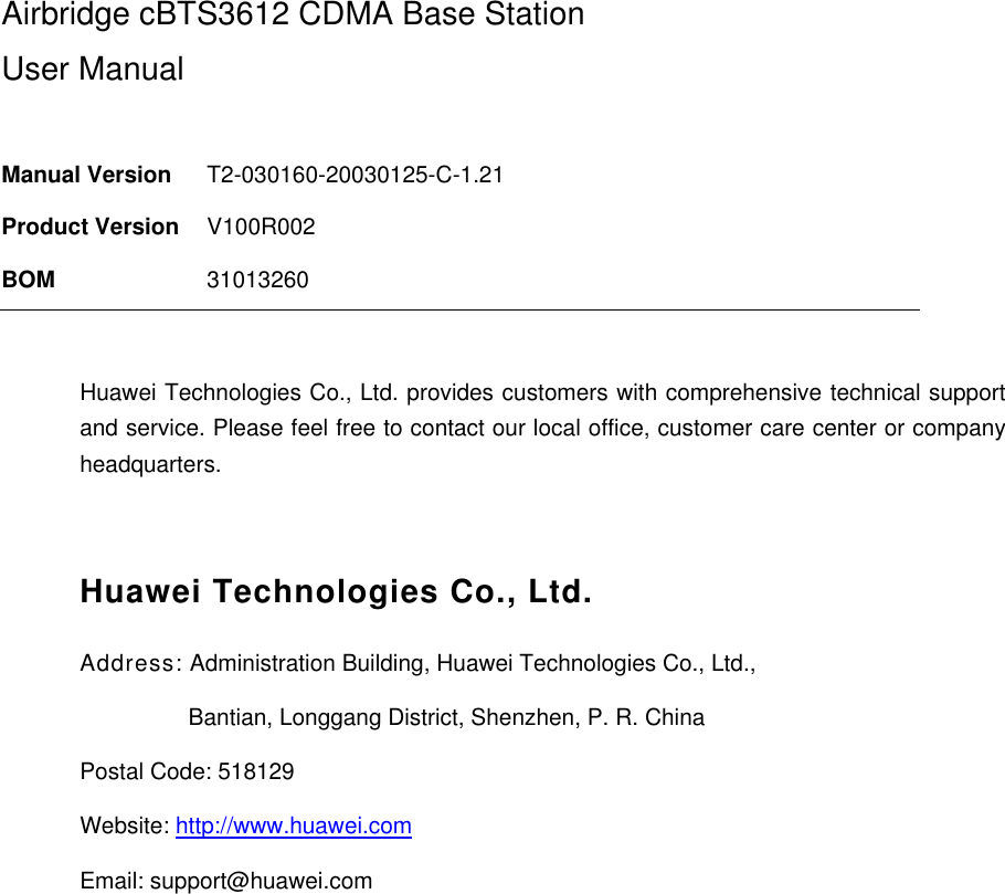
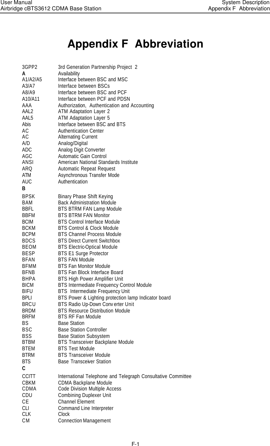
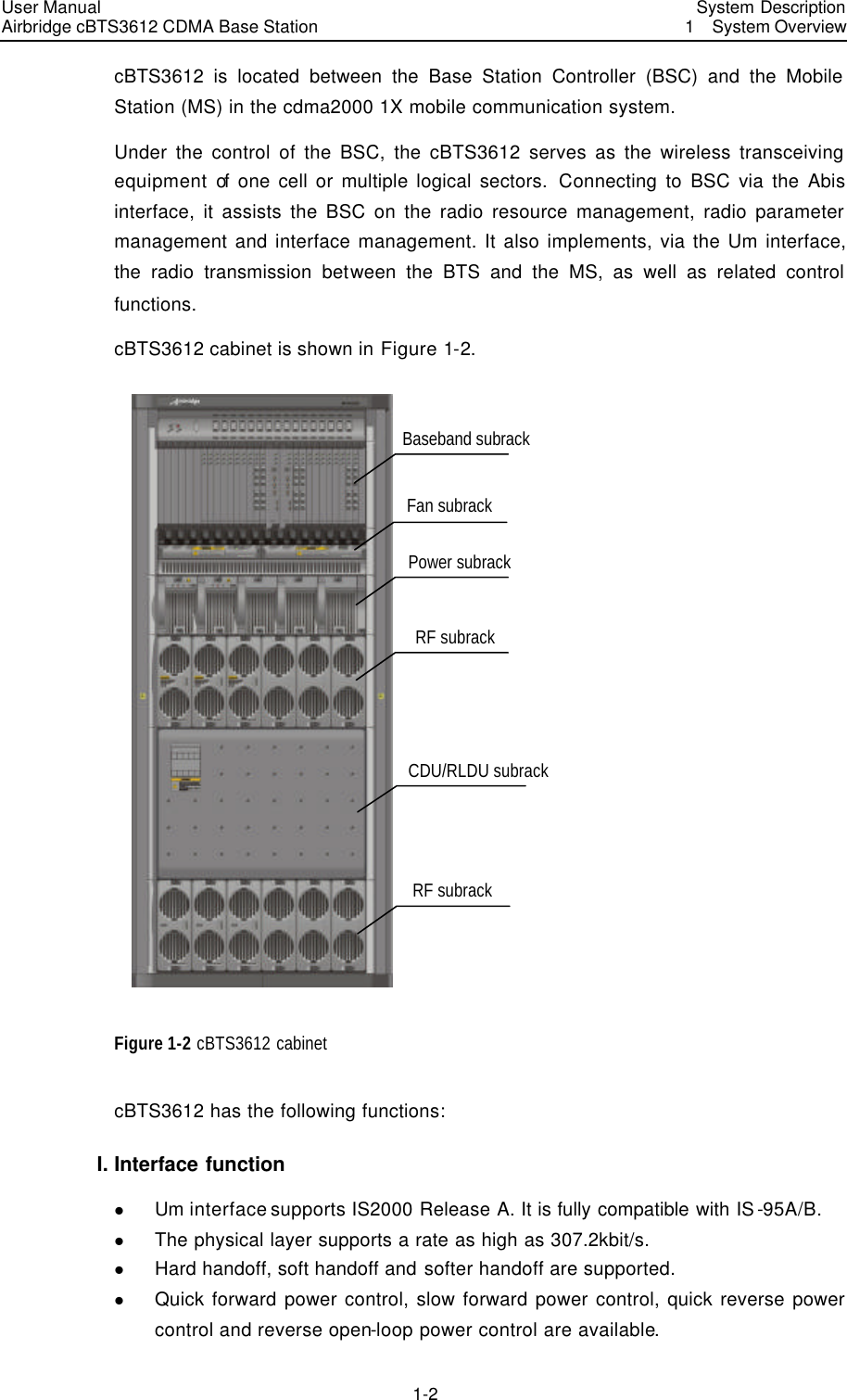
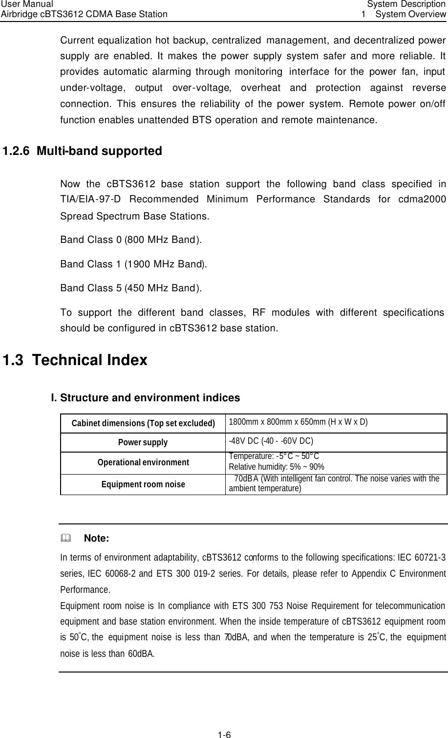
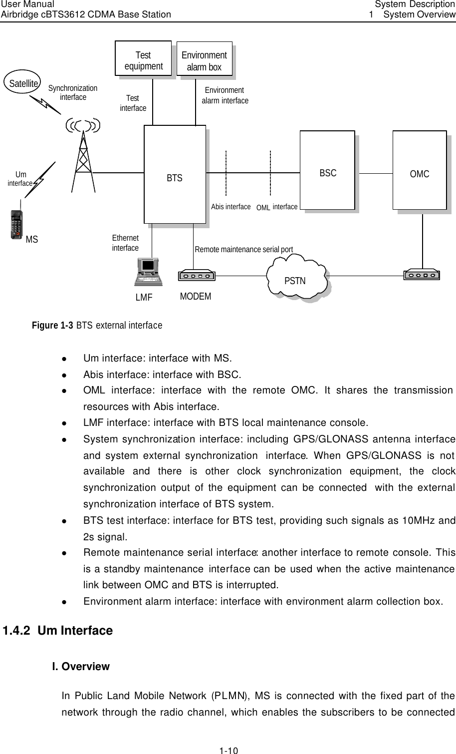
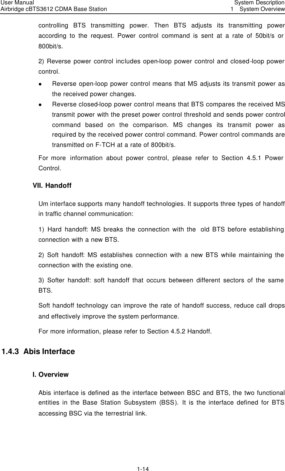
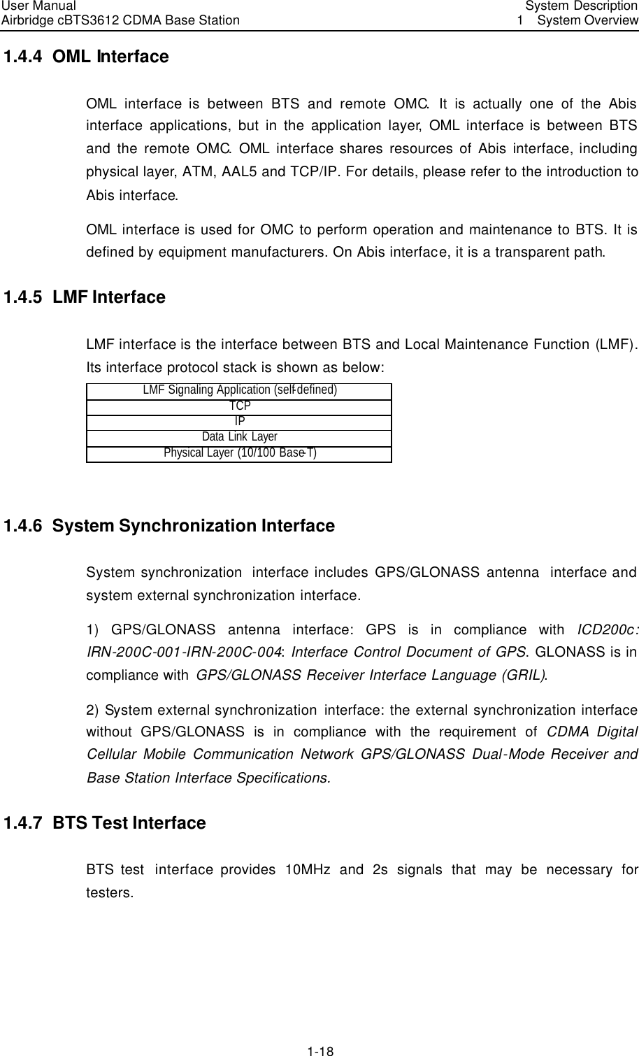
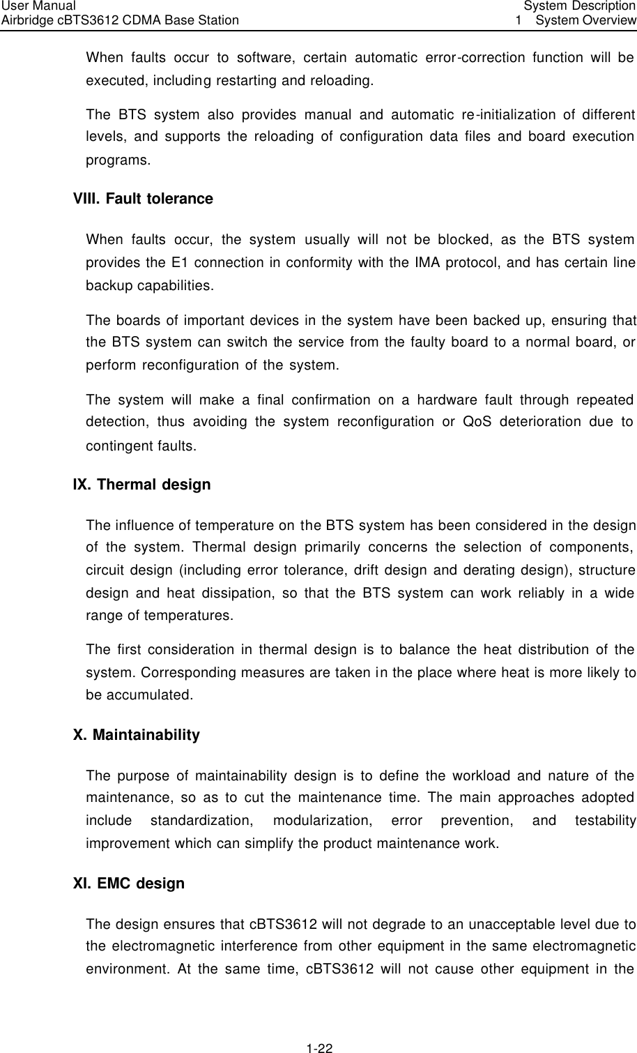
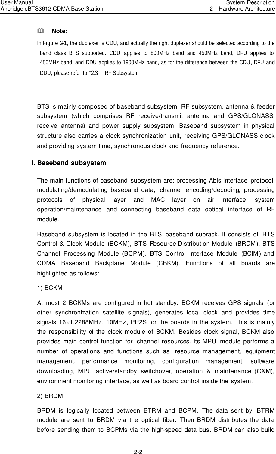
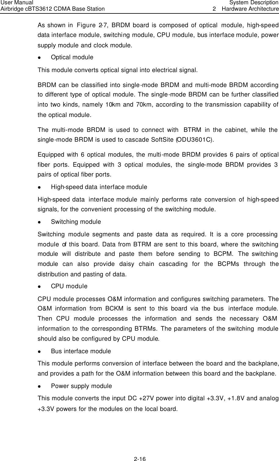
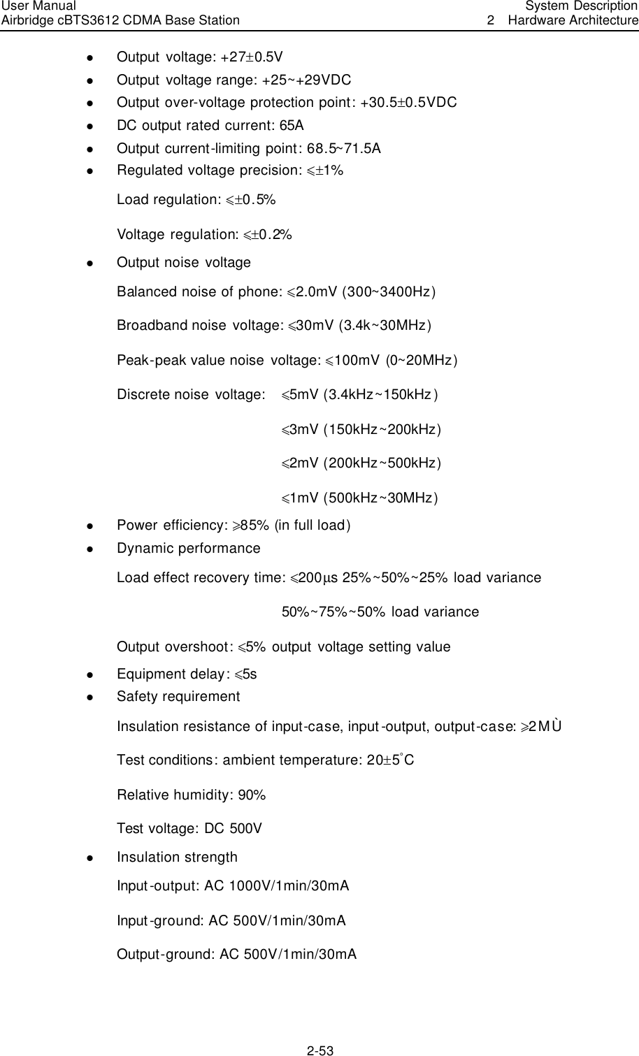
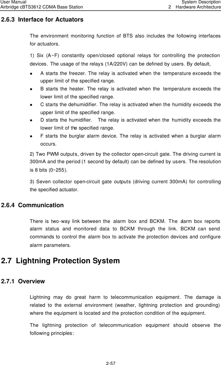
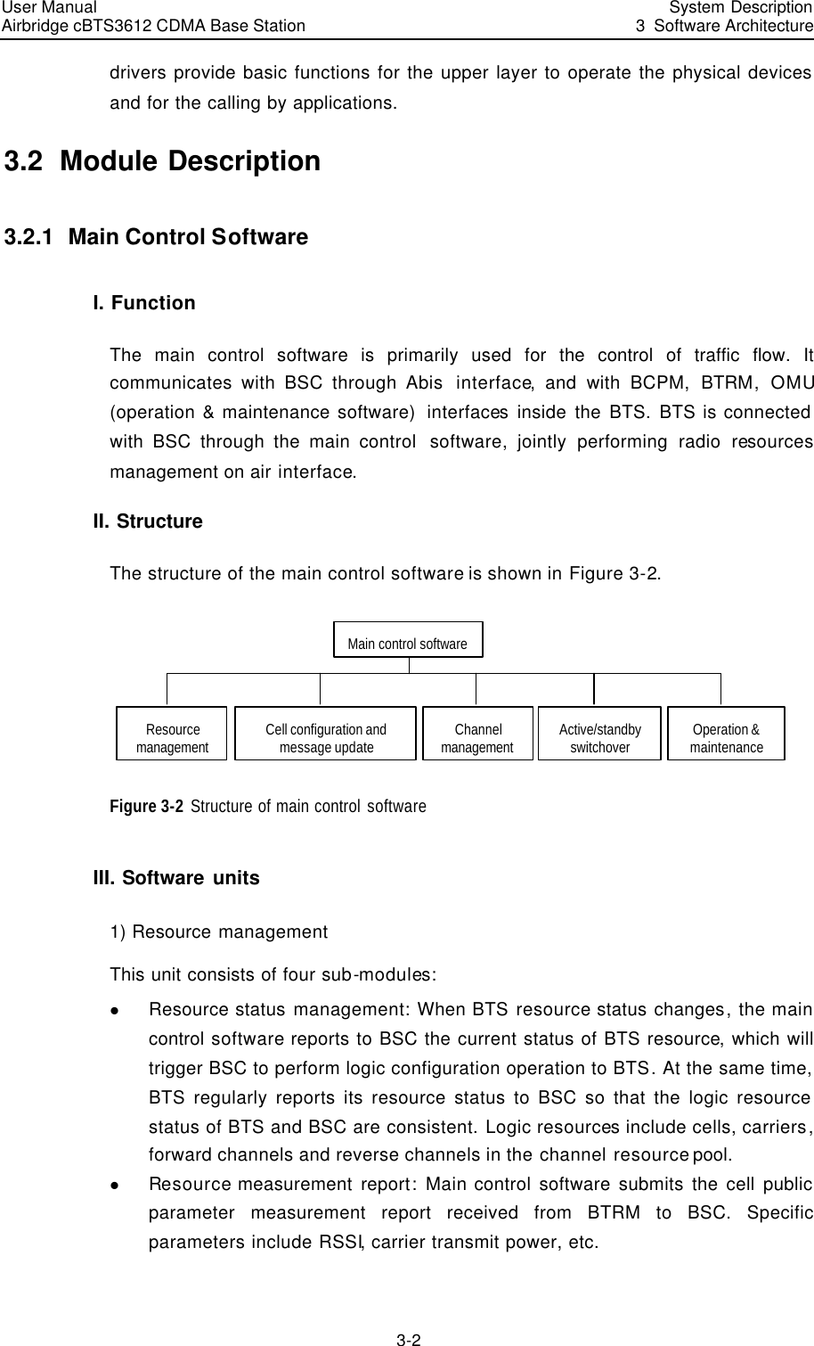
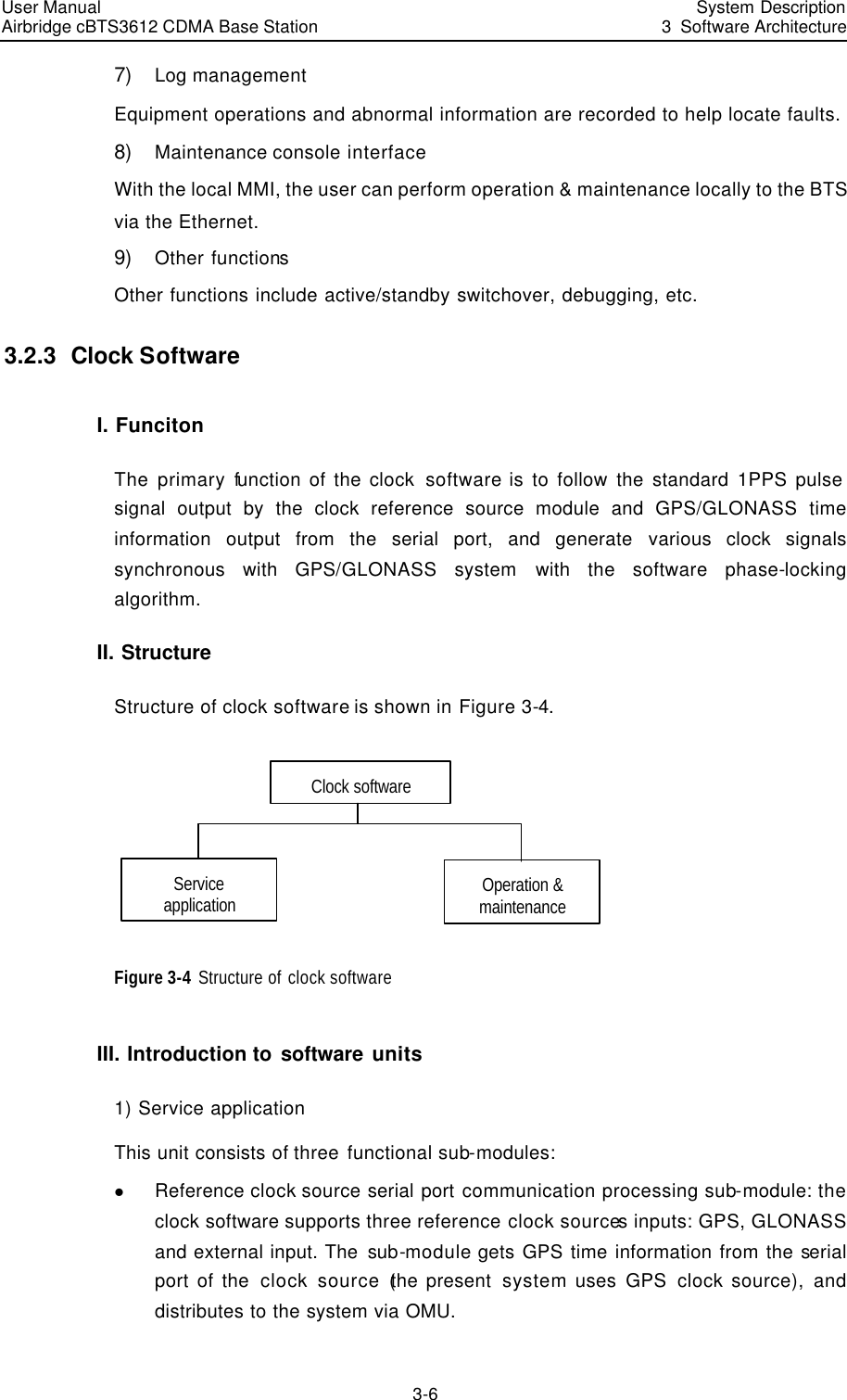
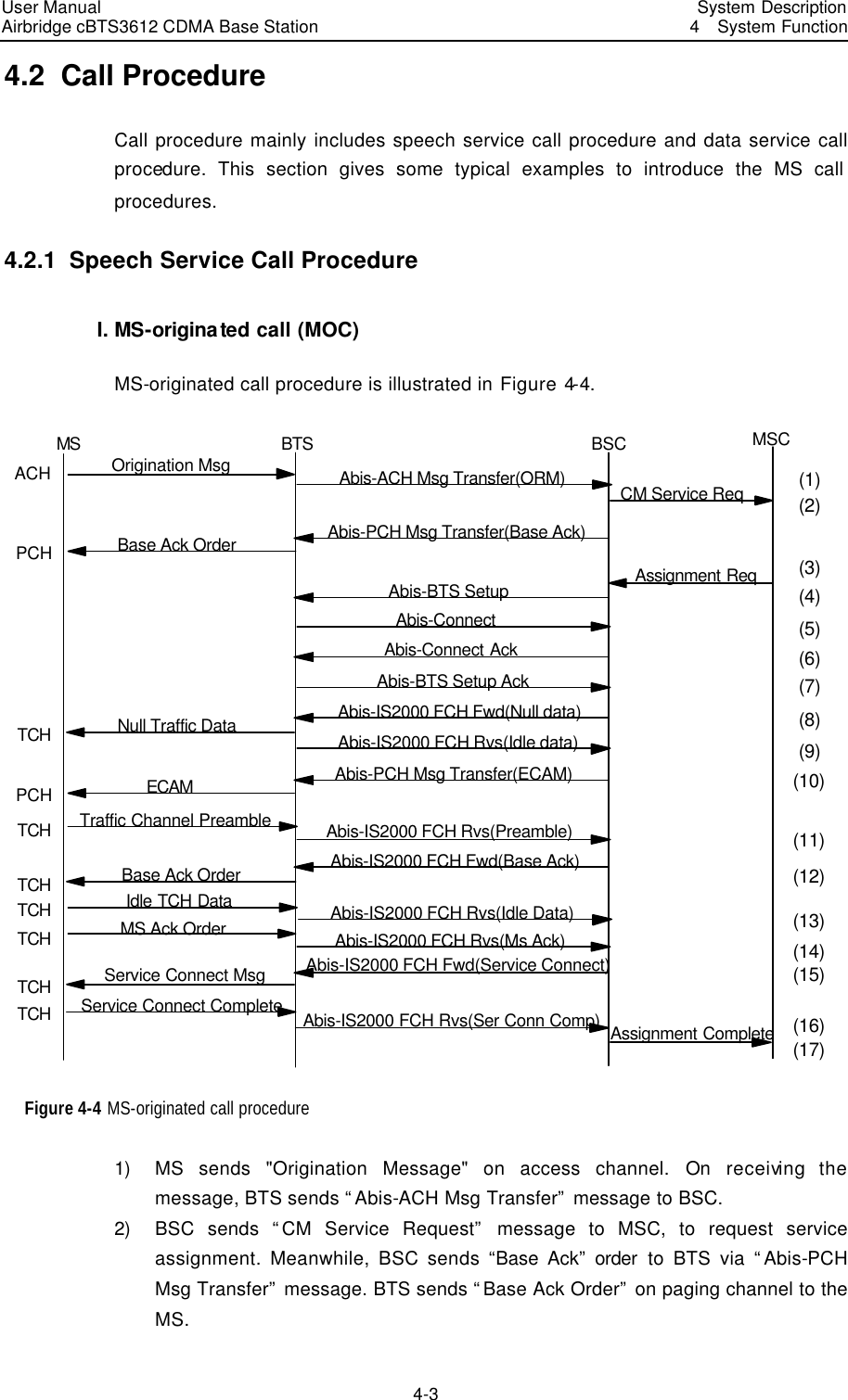
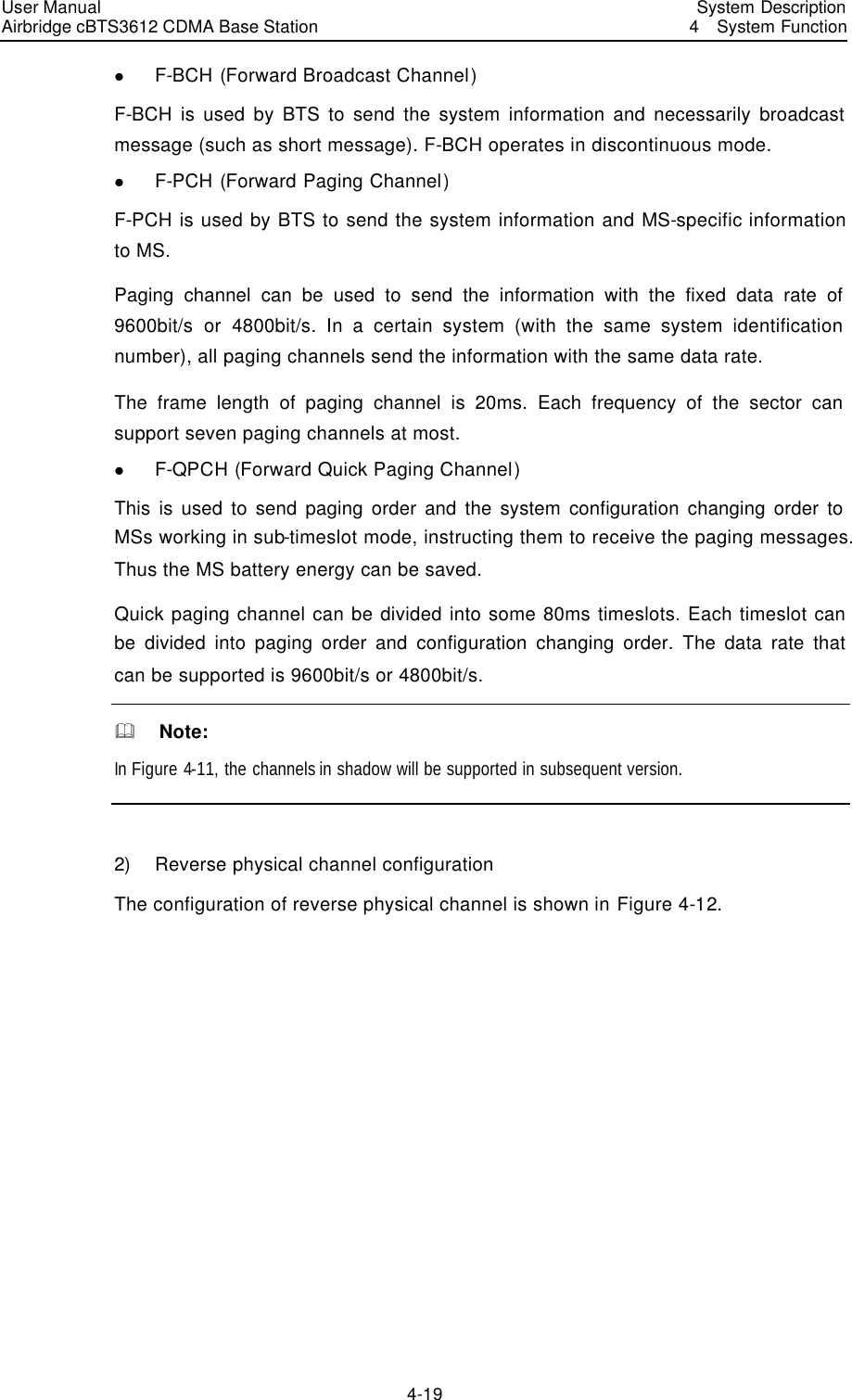
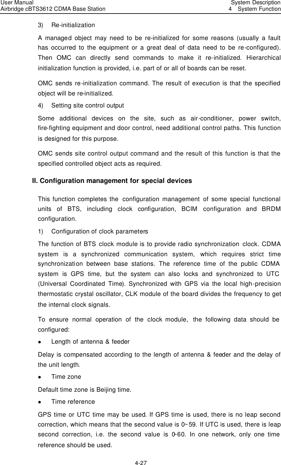
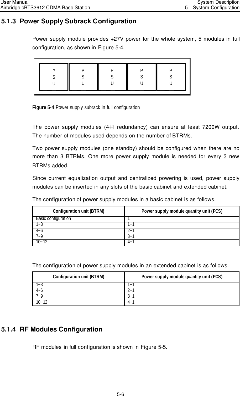
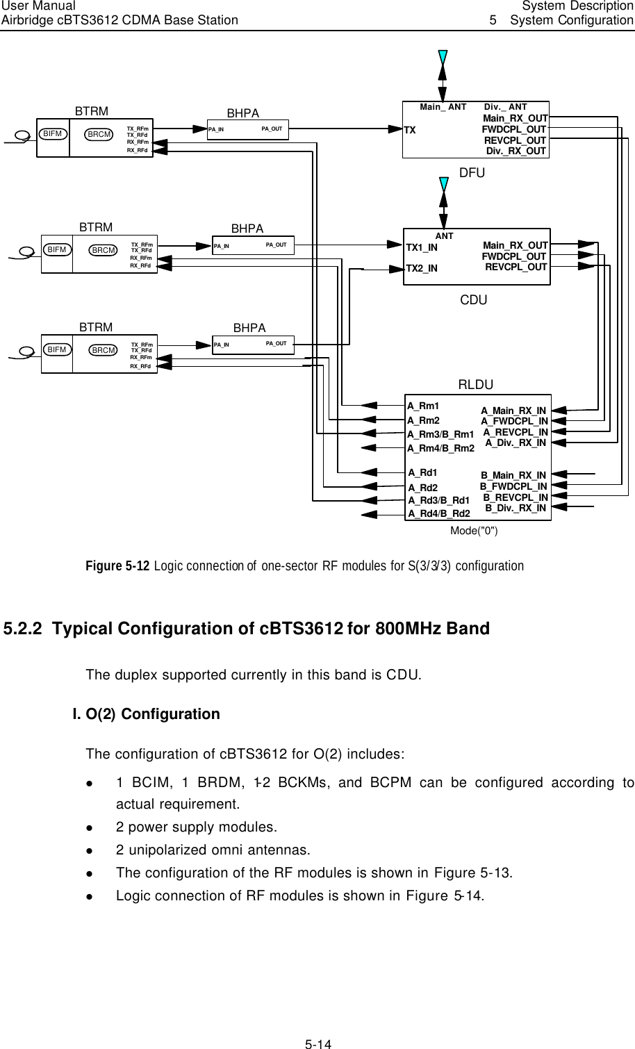
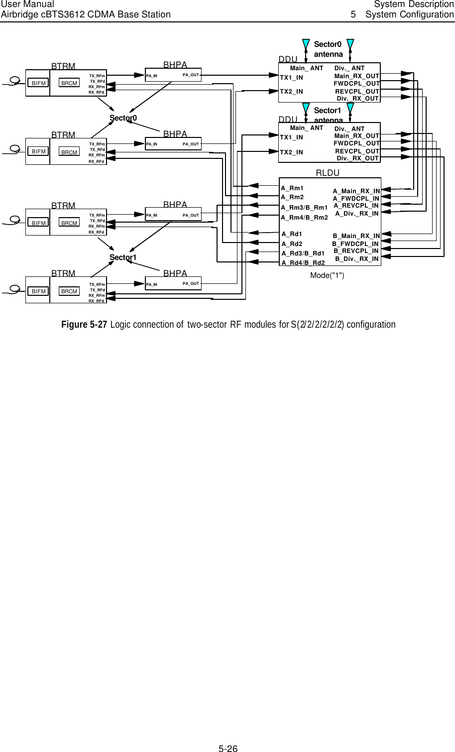
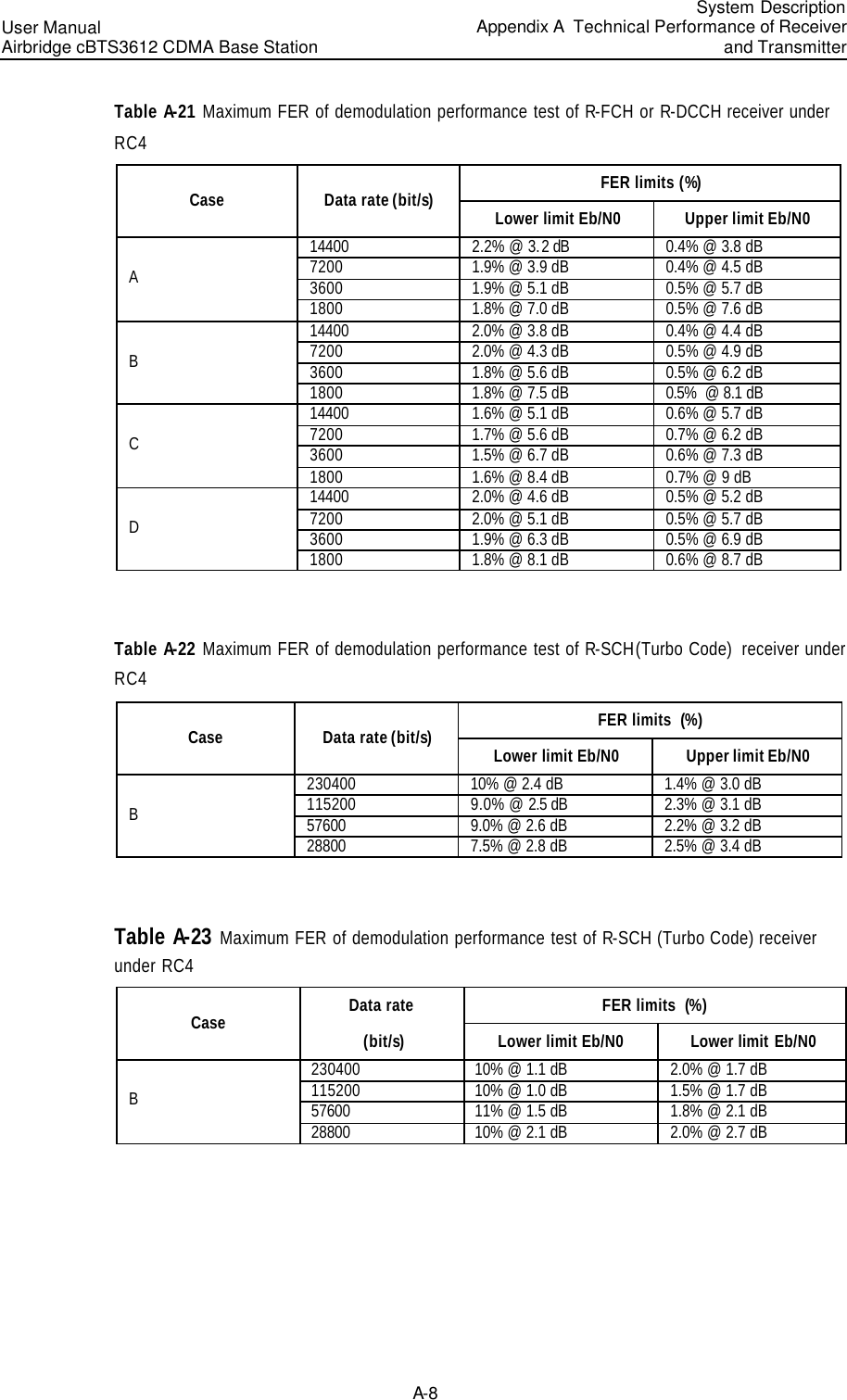
![Conventions This document uses the following conventions: I. General conventions Convention Description Arial Normal paragraphs are in Arial. Arial Narrow Warnings, cautions, notes and tips are in Arial Narrow. Terminal Display Terminal Display is in Courier New; message input by the user via the terminal is in boldface. II. Command conventions Convention Description boldface font Command keywords (which must be input unchanged) are in boldface. italic font Command arguments for which you supply values are in italics. [ ] Elements in square brackets [ ] are optional. { x | y | ... } Alternative keywords are grouped in braces and separated by vertical bars. One is selected. [ x | y | ... ] Optional alternative keywords are grouped in square brackets and separated by vertical bars. One (or none) is selected. { x | y | ... } * Alternative keywords are grouped in braces and separated by vertical bars. A minimum of one and maximum of all can be selected. [ x | y | ... ] * Optional alternative keywords are grouped in square brackets and separated by vertical bars. Many (or none) are selected. ! A line starting with an exclamation mark is comments. III. GUI conventions Convention Description < > Message entered via the terminal is within angle brackets. [ ] MMIs, menu items, data table and field names are inside square brackets [ ]. / Multi-level menus are separated by forward slashes (/). Menu items are in boldface. For example, [File/Create/Folder].](https://usermanual.wiki/Huawei-Technologies/CBTS3612-1900.User-Manual/User-Guide-358829-Page-12.png)
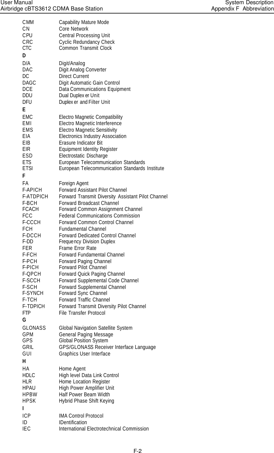
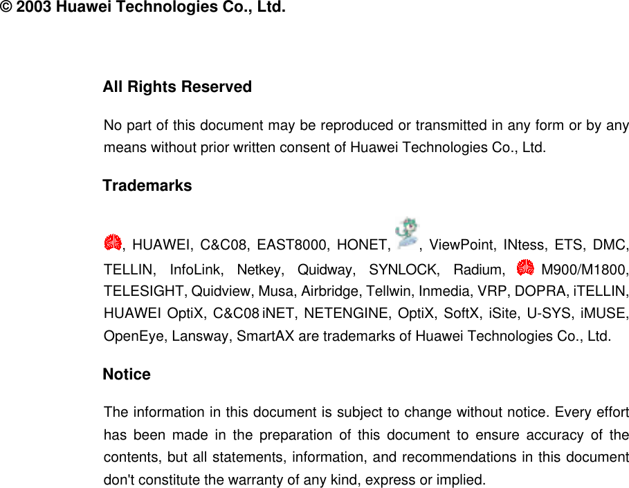
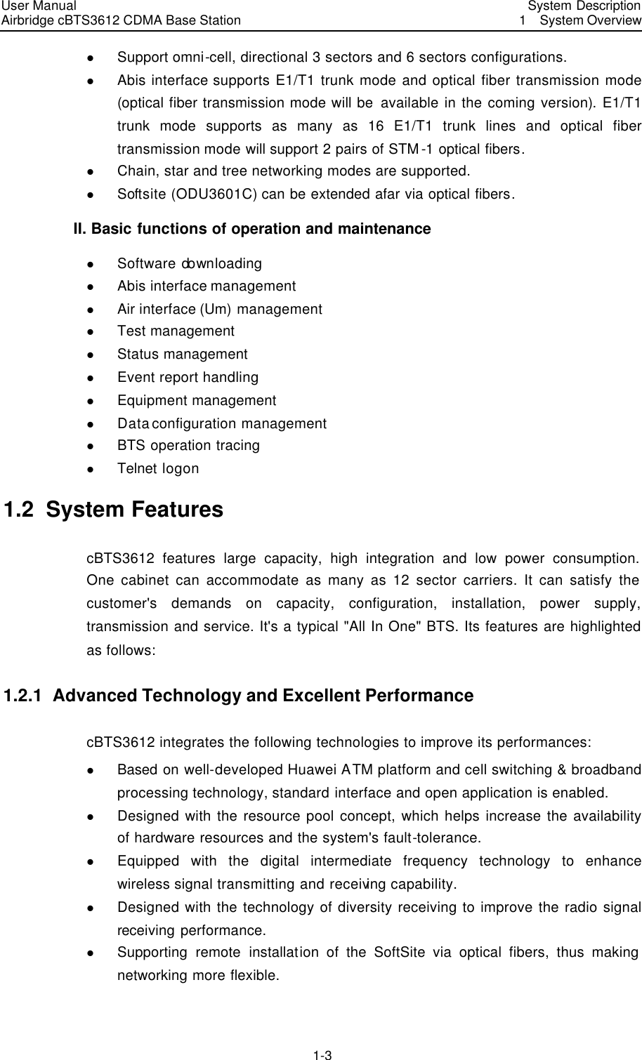
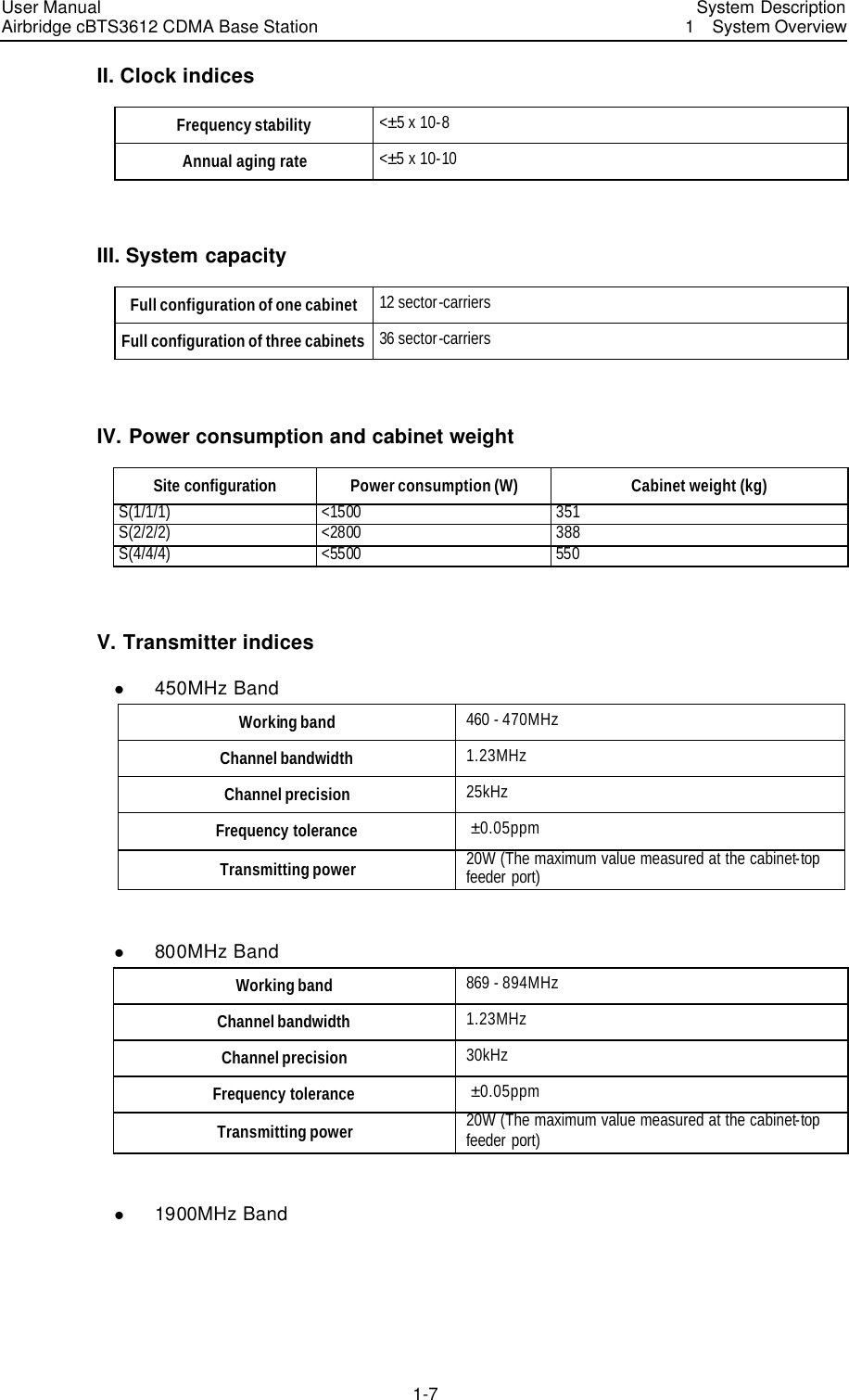
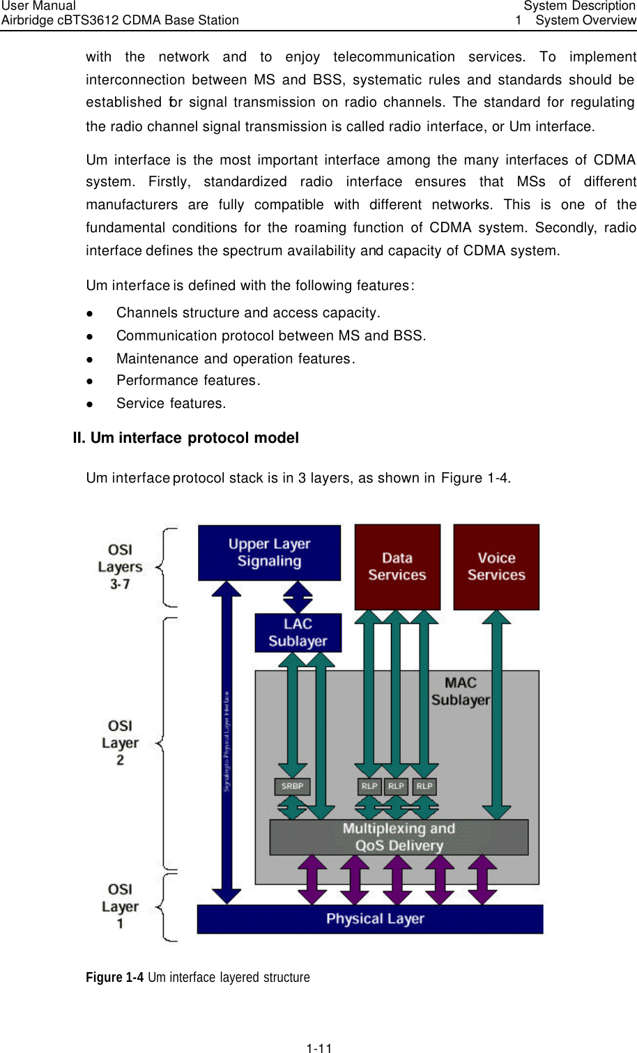
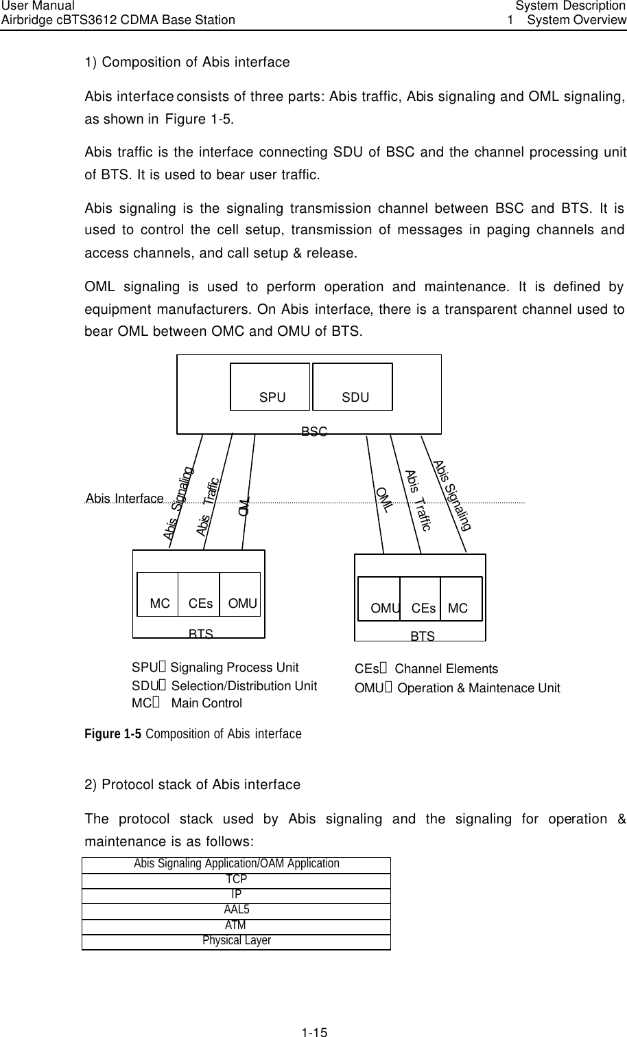
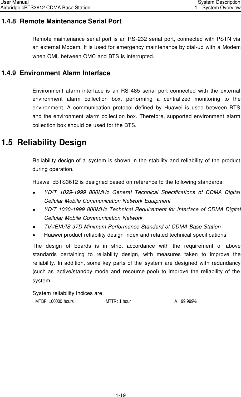
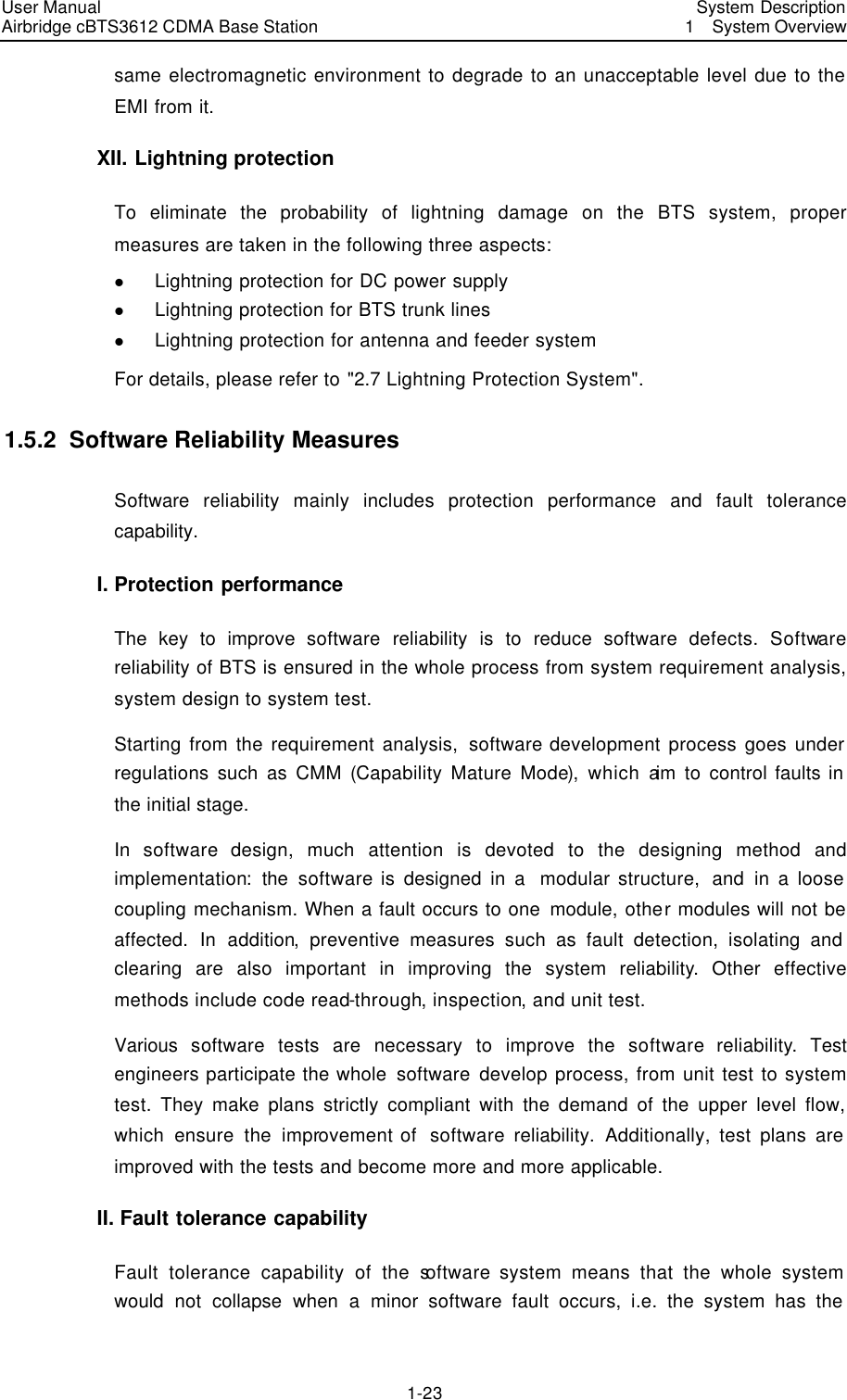
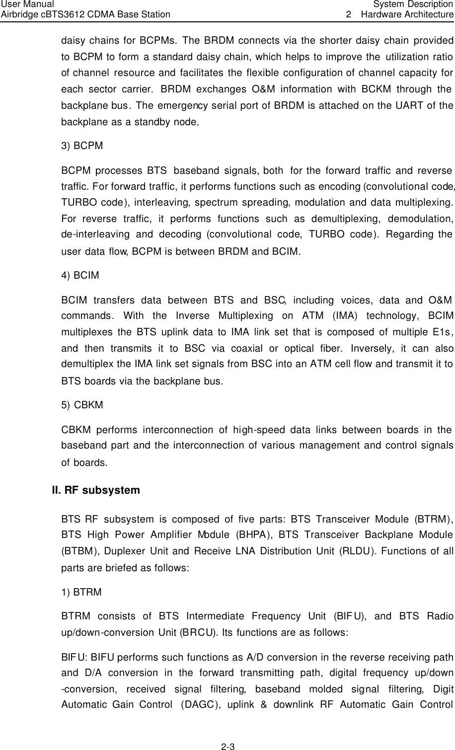
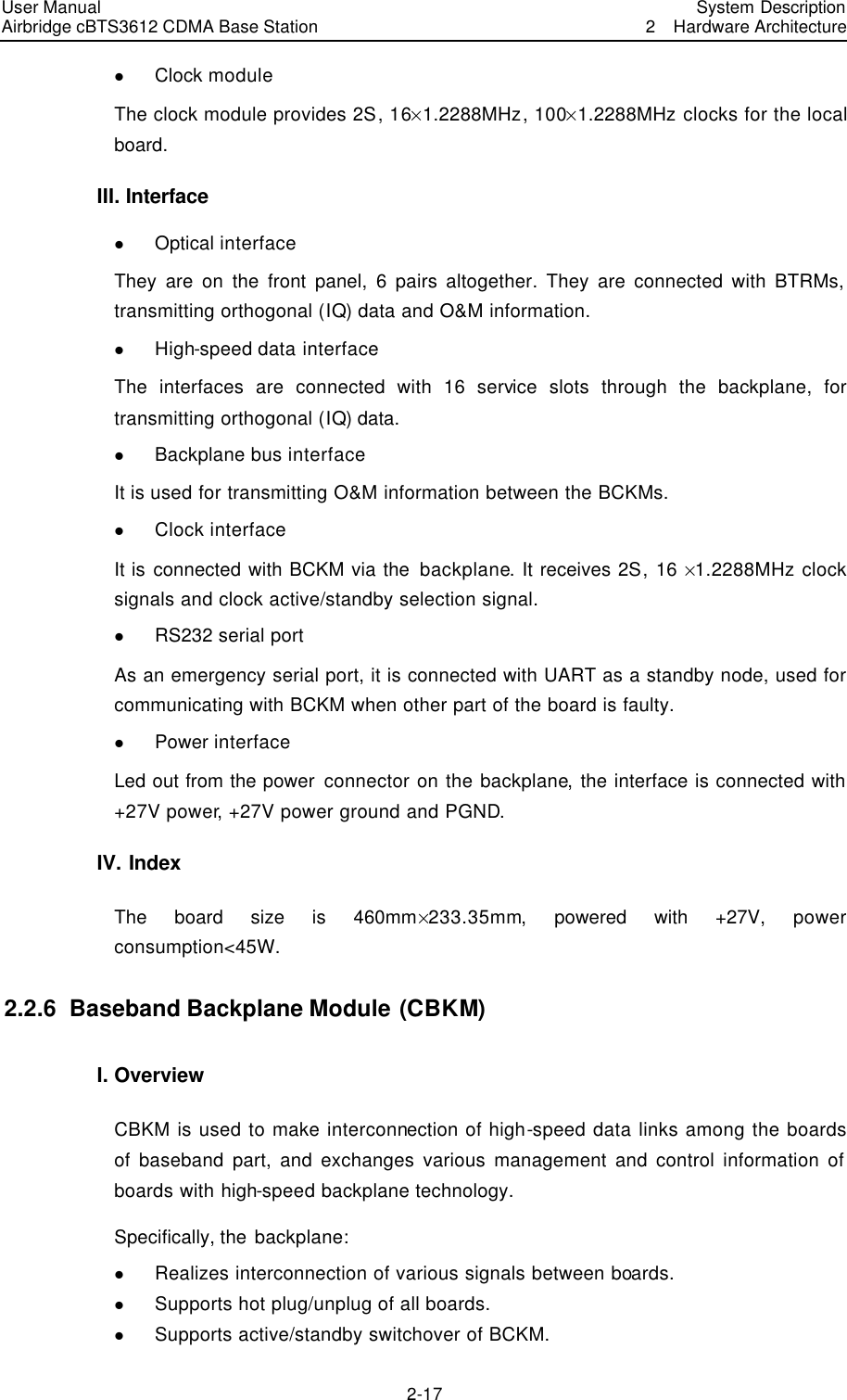
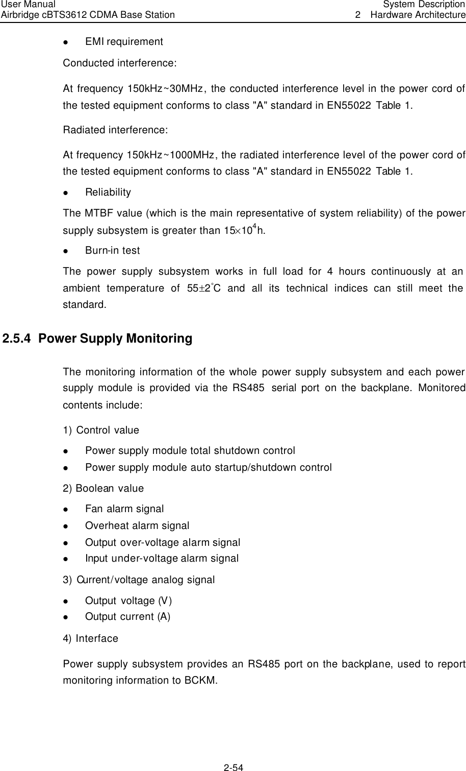
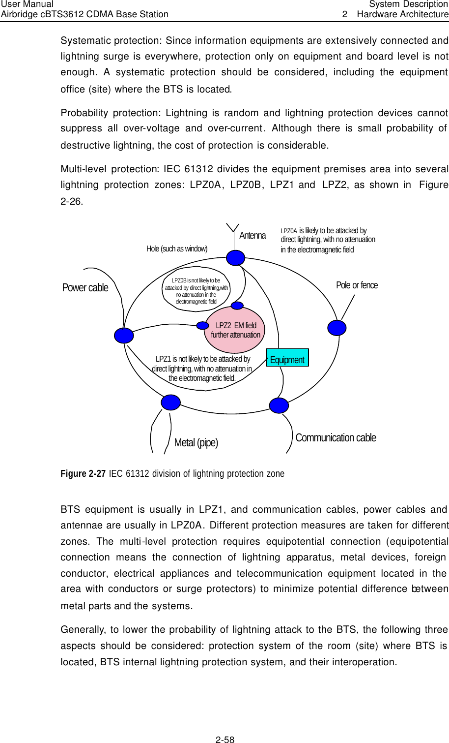
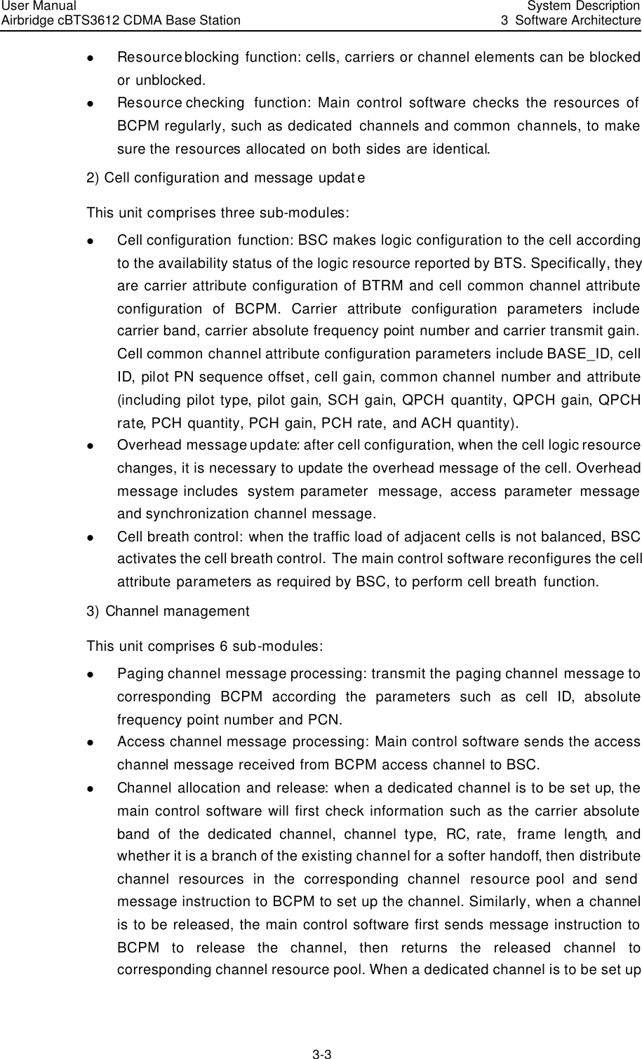
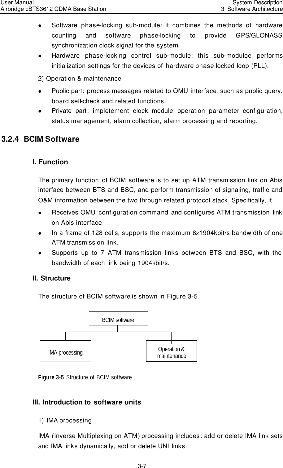
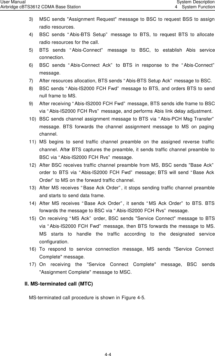
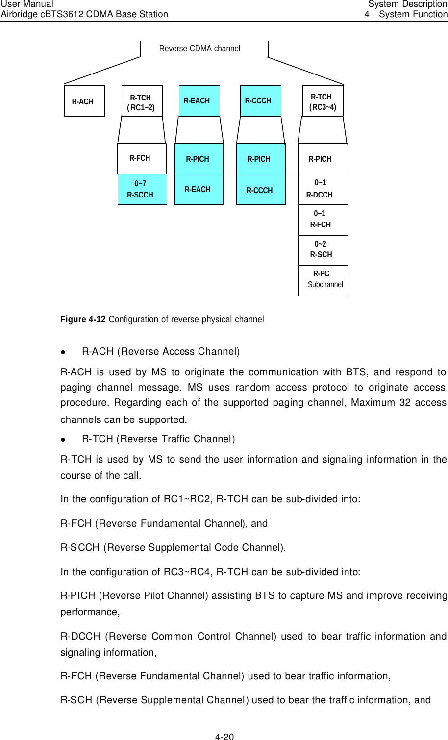
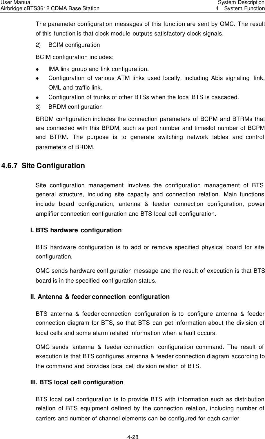
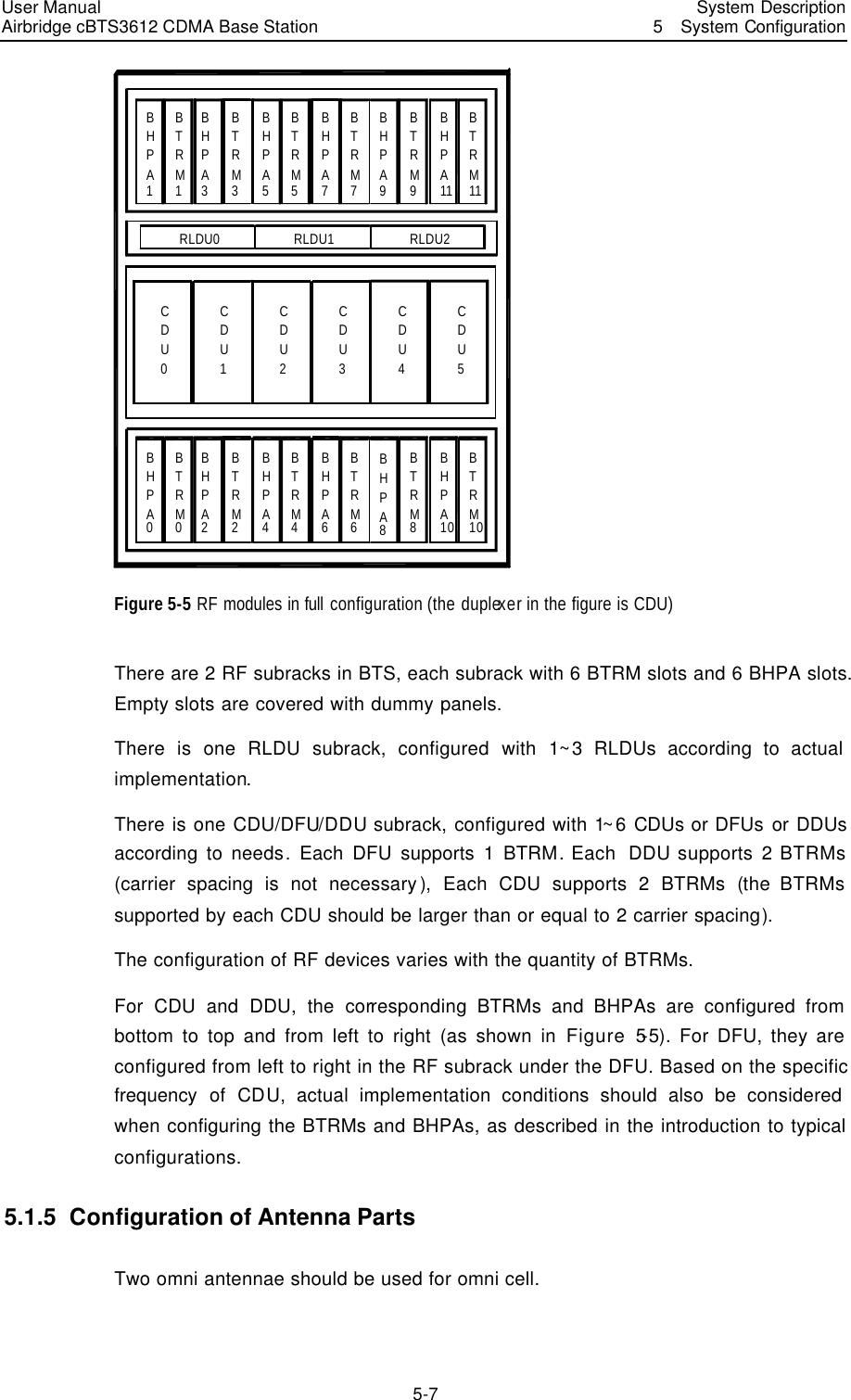
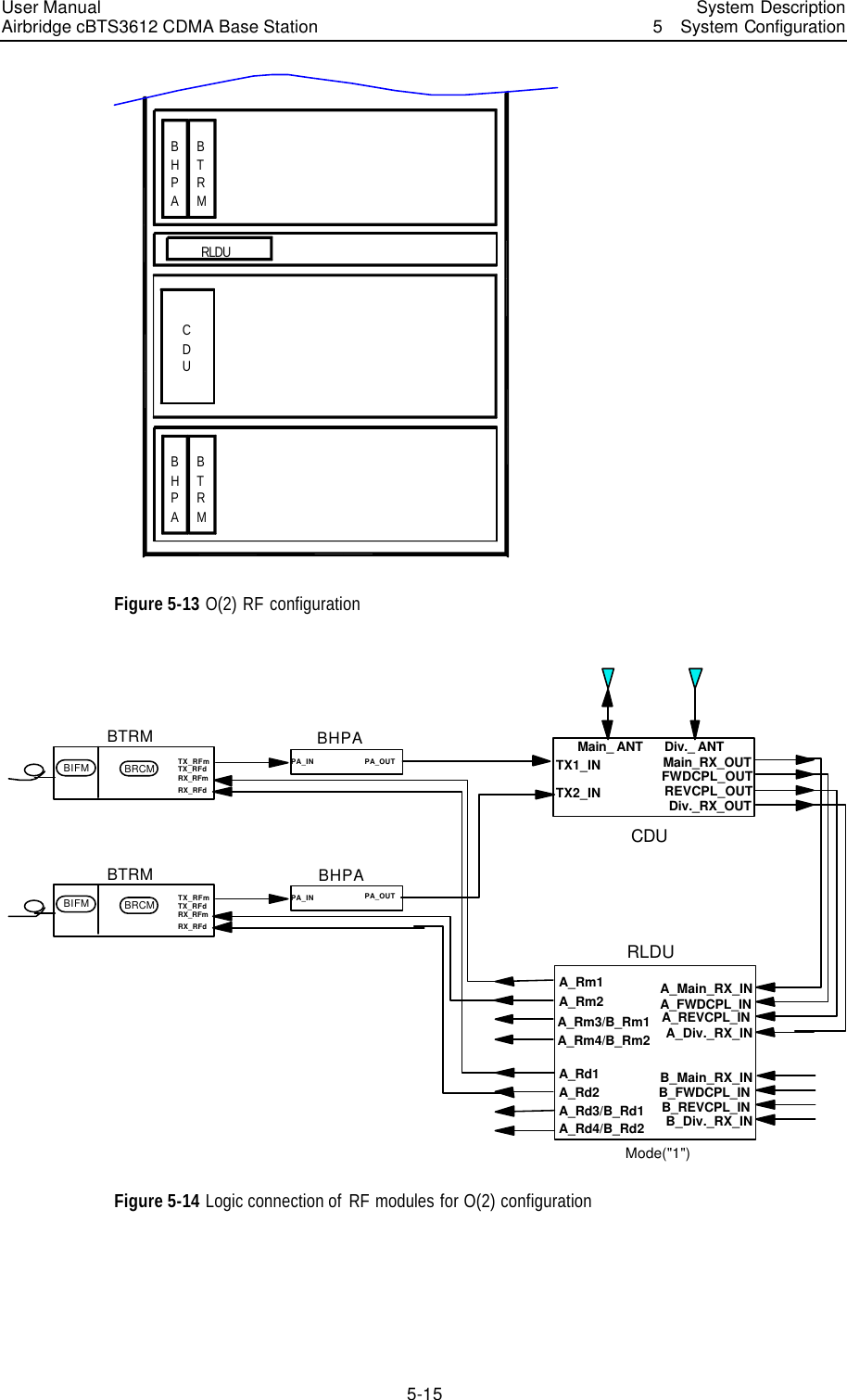
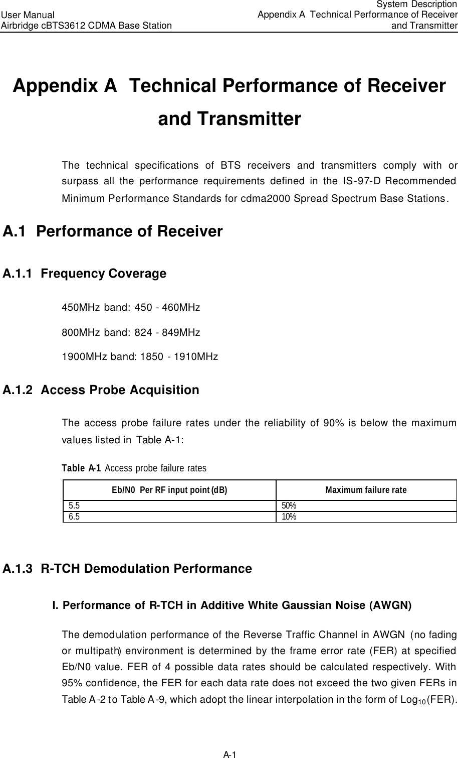
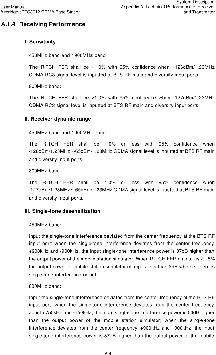
![IV. Keyboard operation Format Description <Key> Press the key with key name expressed with a pointed bracket, e.g. <Enter>, <Tab>, <Backspace>, or<A>. <Key1+Key2> Press the keys concurrently; e.g. <Ctrl+Alt+A>means the three keys should be pressed concurrently. <Key1, Key2> Press the keys in turn, e.g. <Alt, A>means the two keys should be pressed in turn. [Menu Option] The item with a square bracket indicates the menu option, e.g. [System] option on the main menu. The item with a pointed bracket indicates the functional button option, e.g. <OK> button on some interface. [Menu1/Menu2/Menu3] Multi-level menu options, e.g. [System/Option/Color setup] on the main menu indicates [Color Setup] on the menu option of [Option], which is on the menu option of [System]. V. Mouse operation Action Description Click Press the left button or right button quickly (left button by default). Double Click Press the left button twice continuously and quickly. Drag Press and hold the left button and drag it to a certain position. VI. Symbols Eye-catching symbols are also used in this document to highlight the points worthy of special attention during the operation. They are defined as follows: Caution, Warning, Danger: Means reader be extremely careful during the operation. Note Comment, Tip, Knowhow, Thought: Means a complementary description.](https://usermanual.wiki/Huawei-Technologies/CBTS3612-1900.User-Manual/User-Guide-358829-Page-13.png)
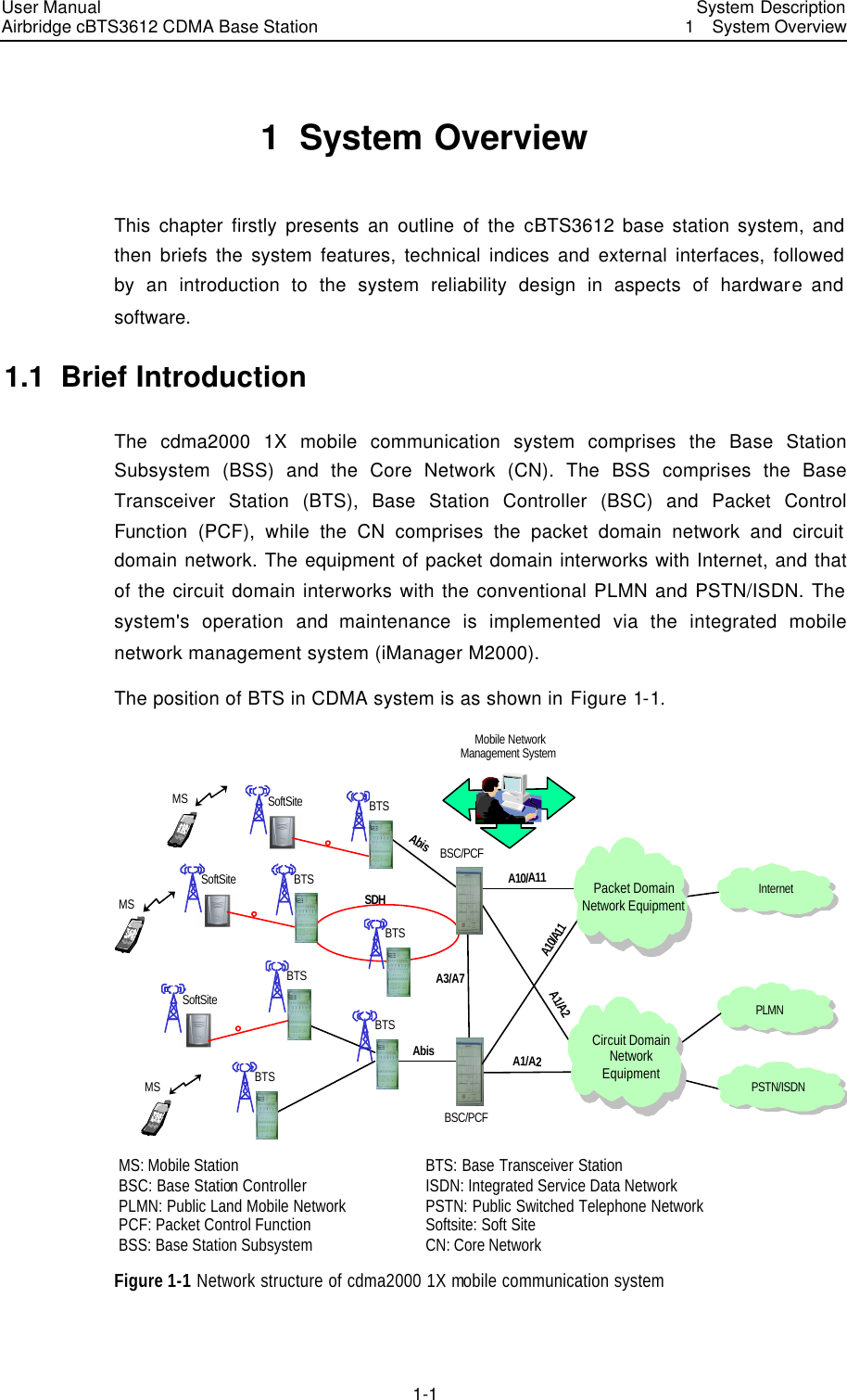
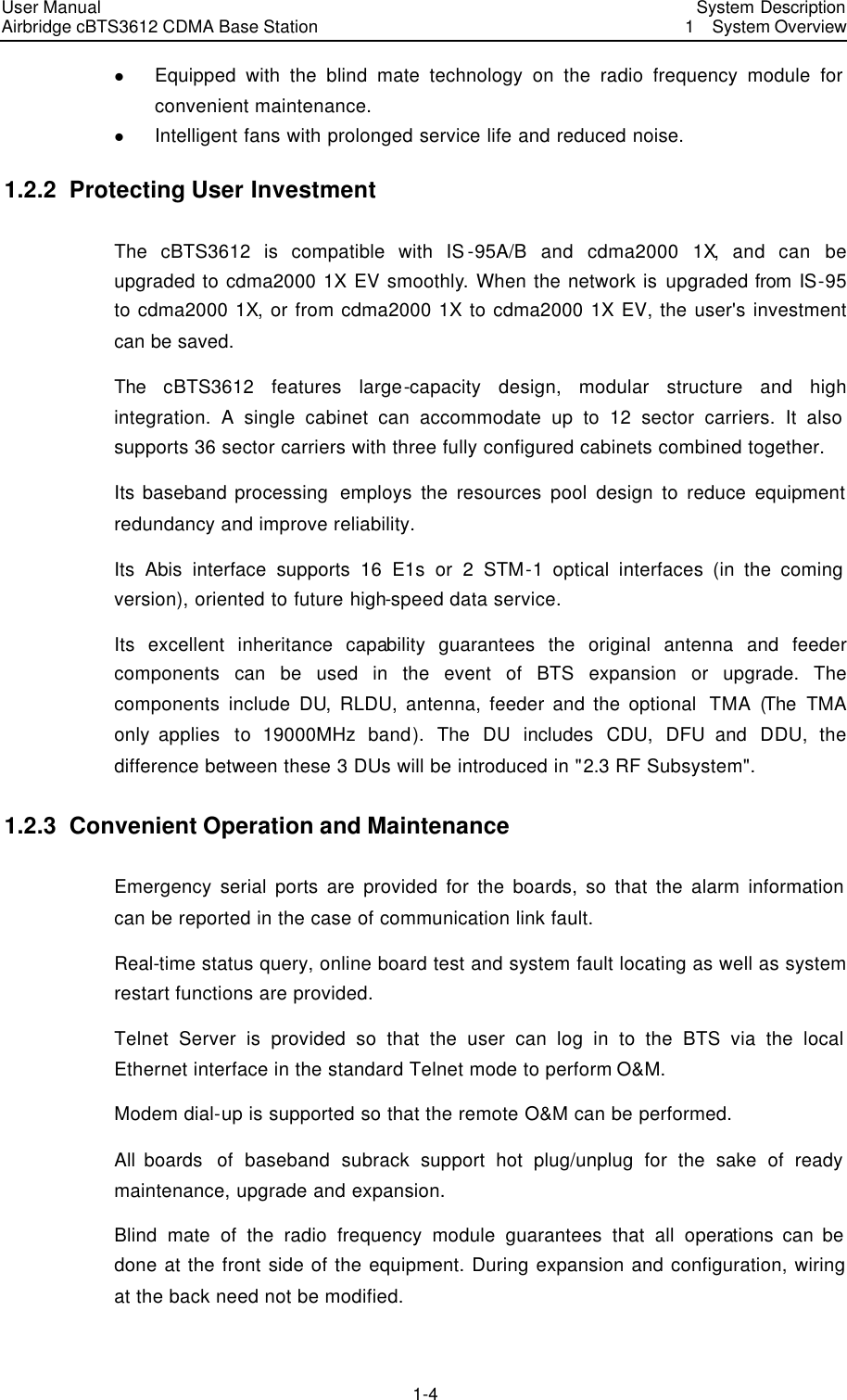
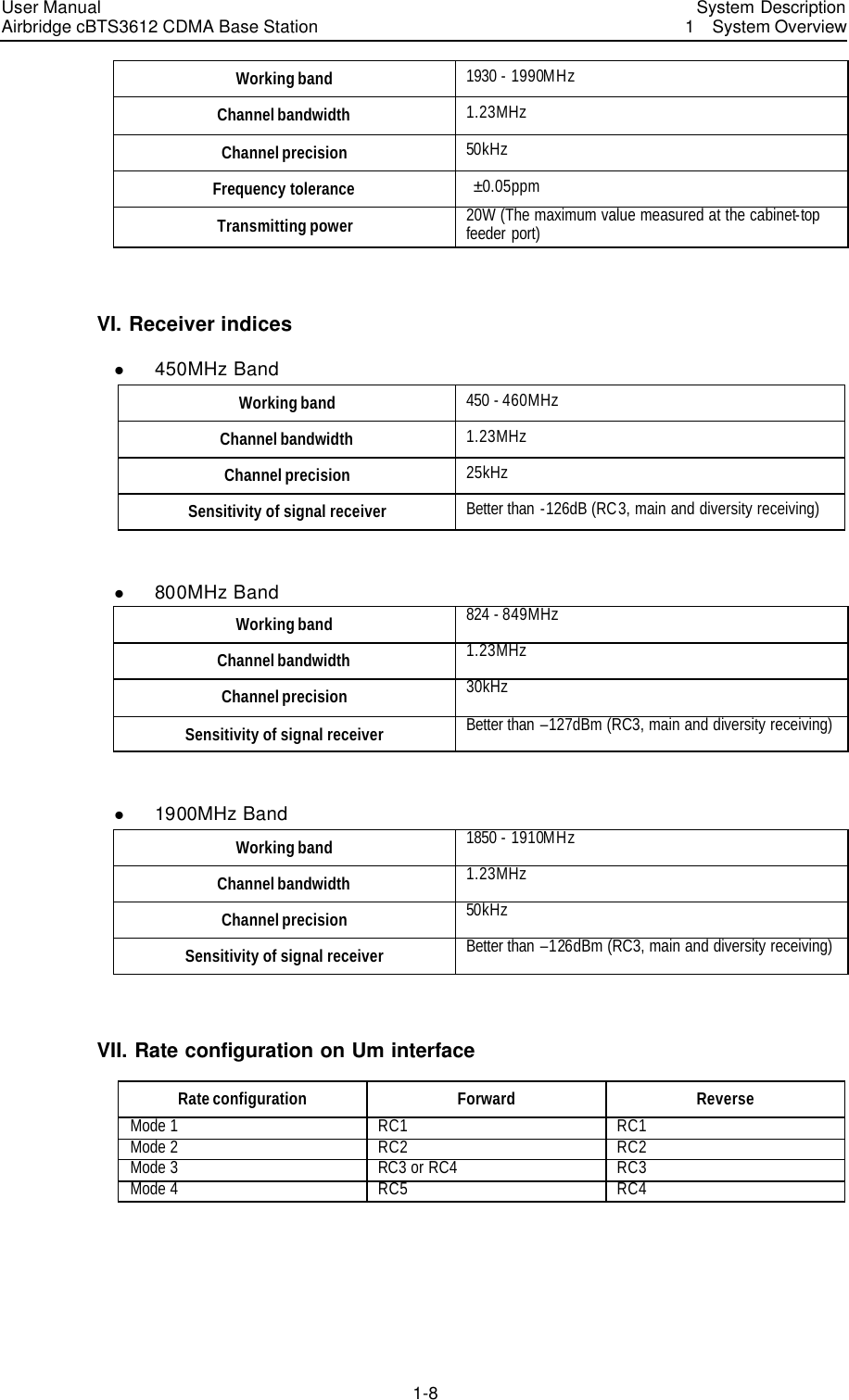
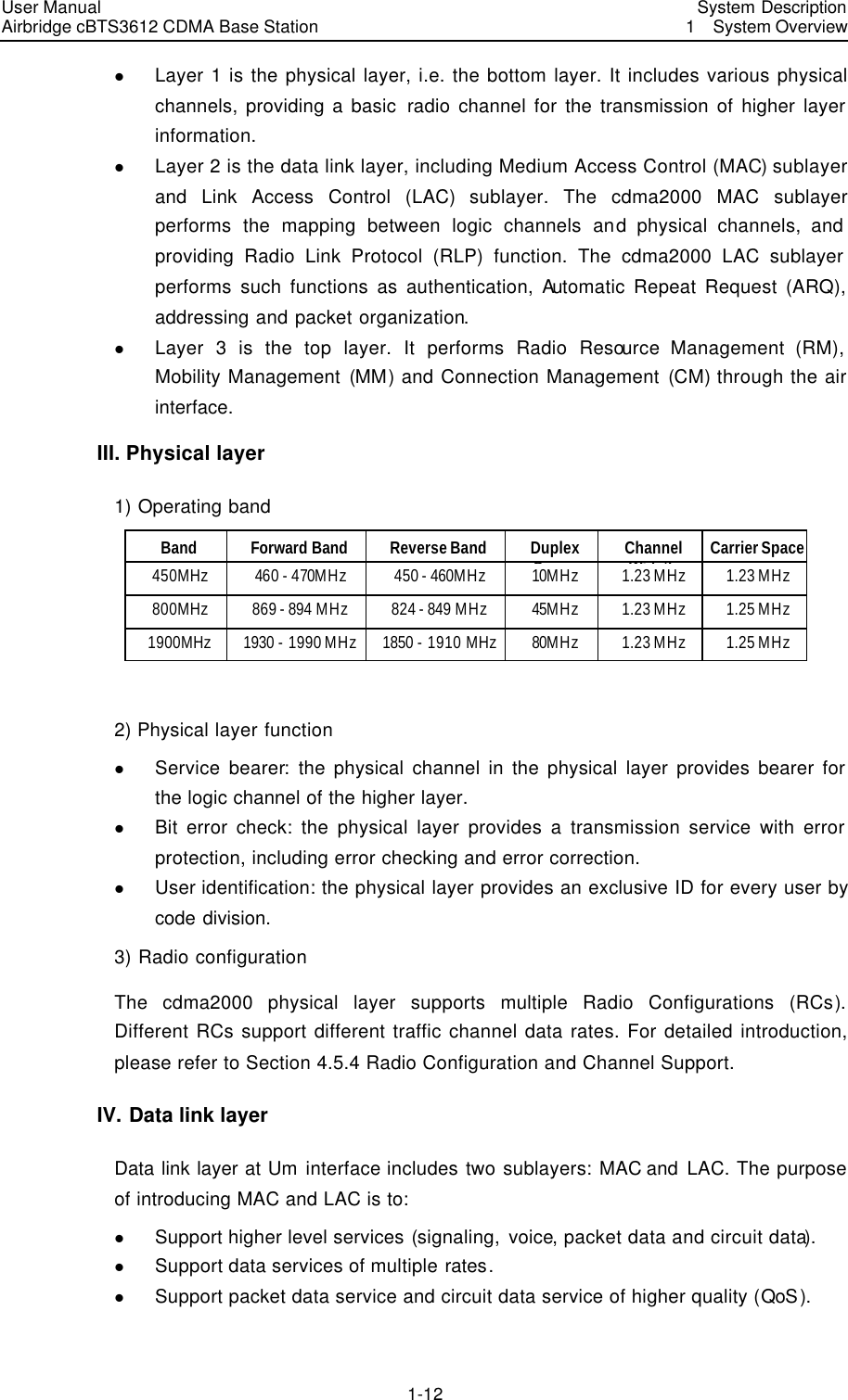
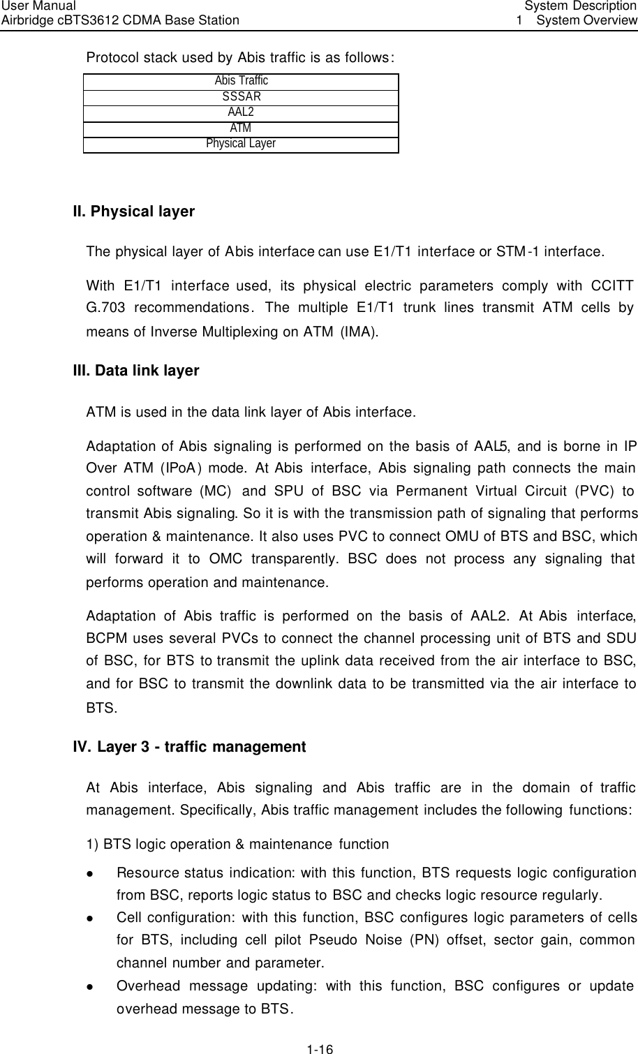
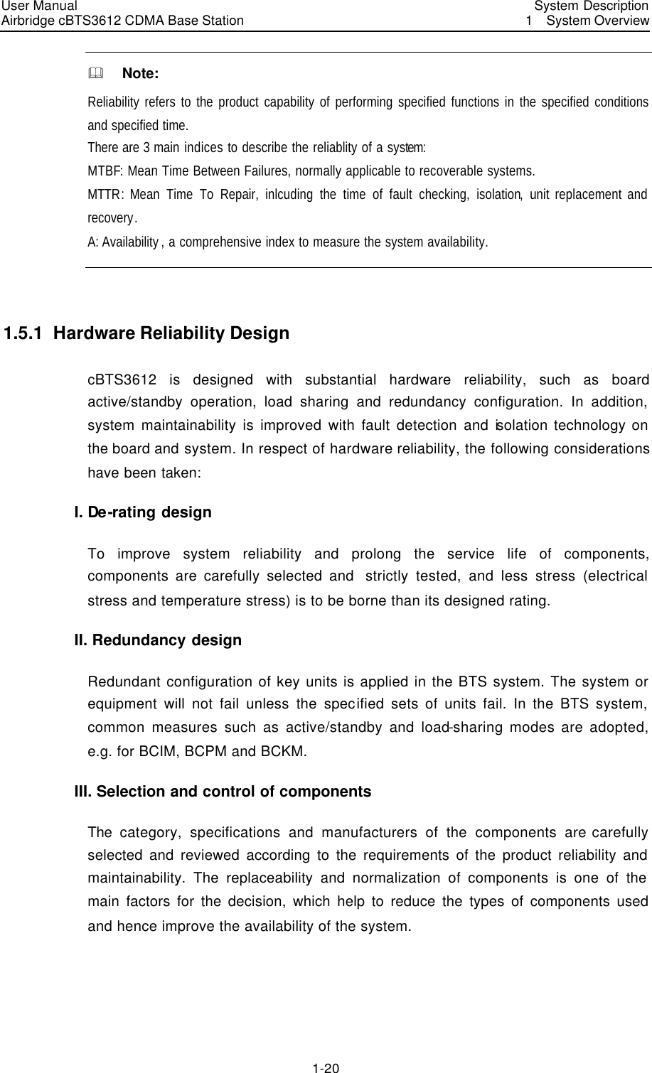
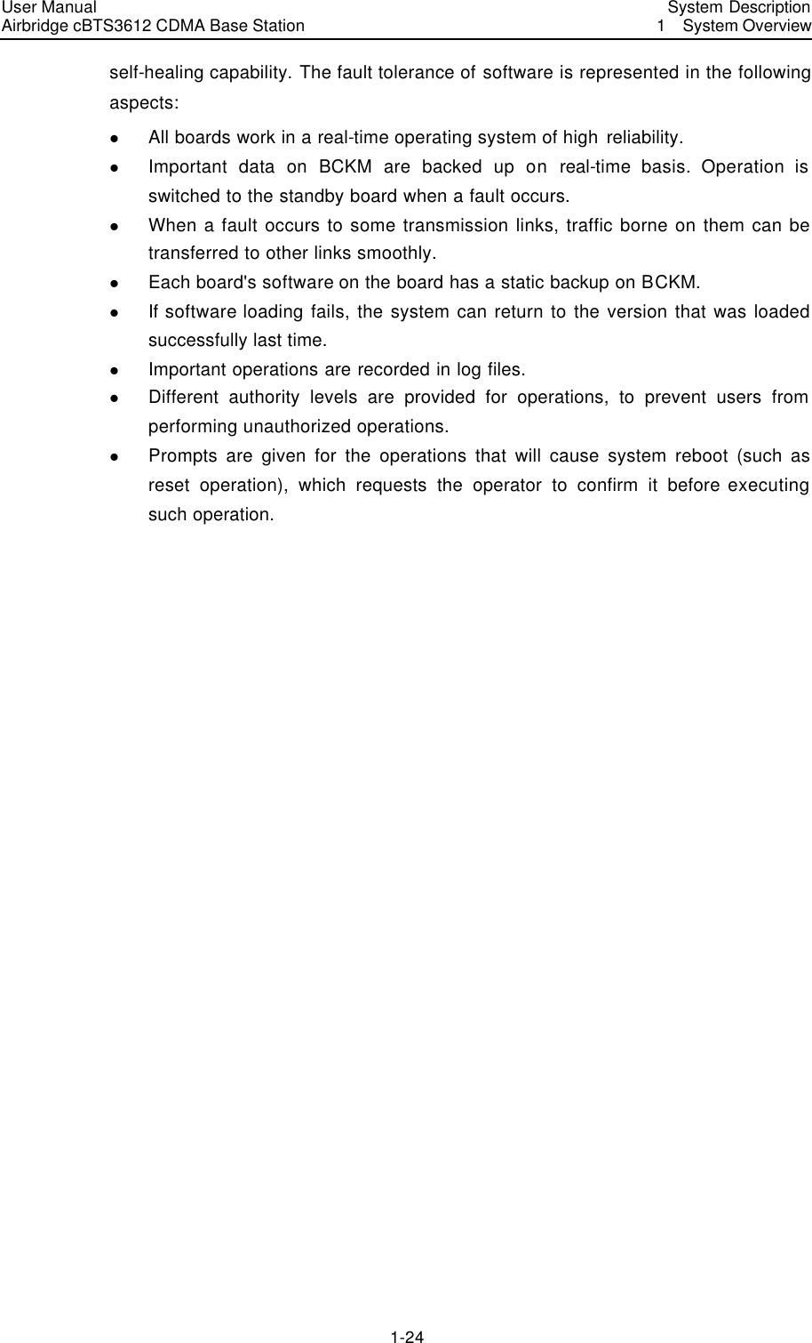
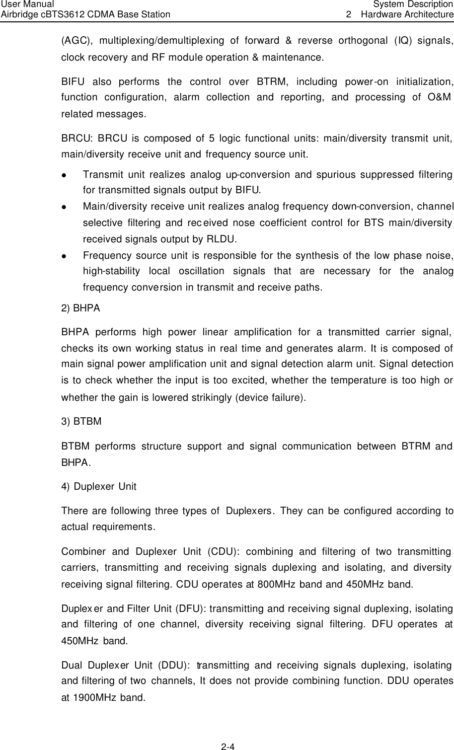


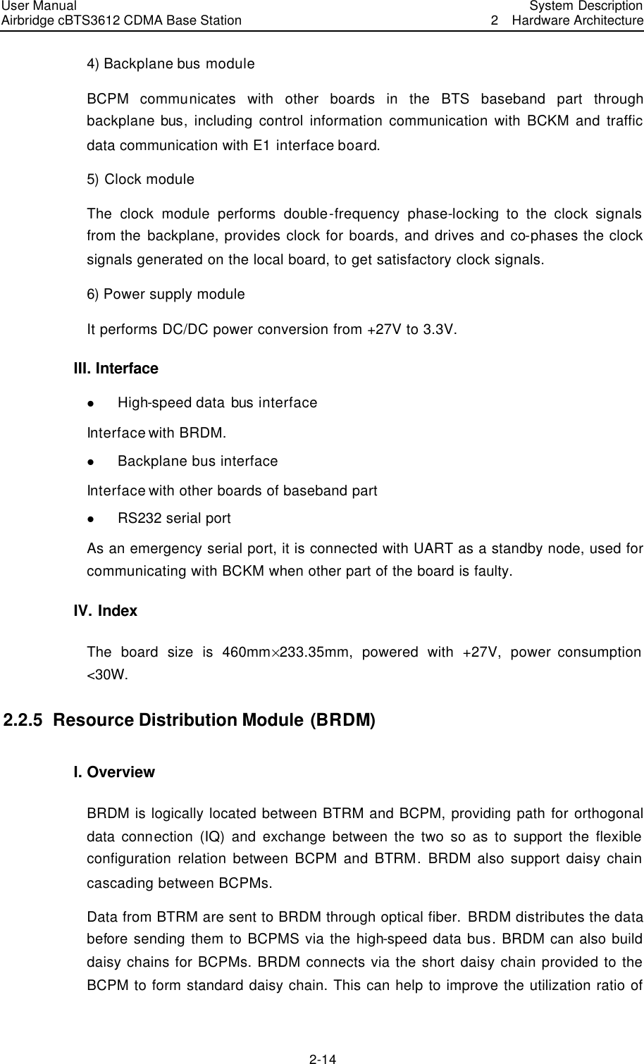
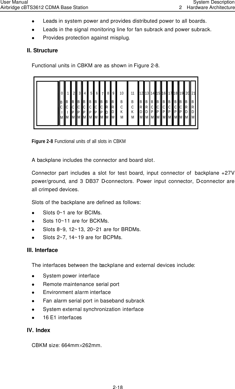

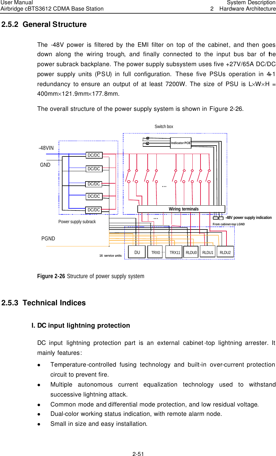
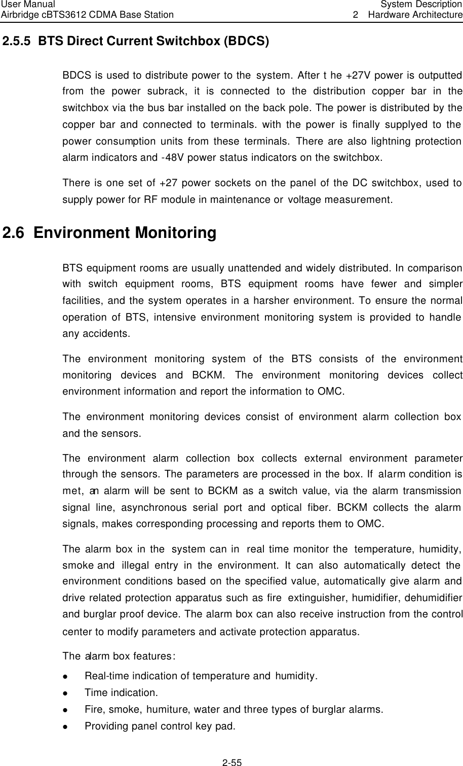
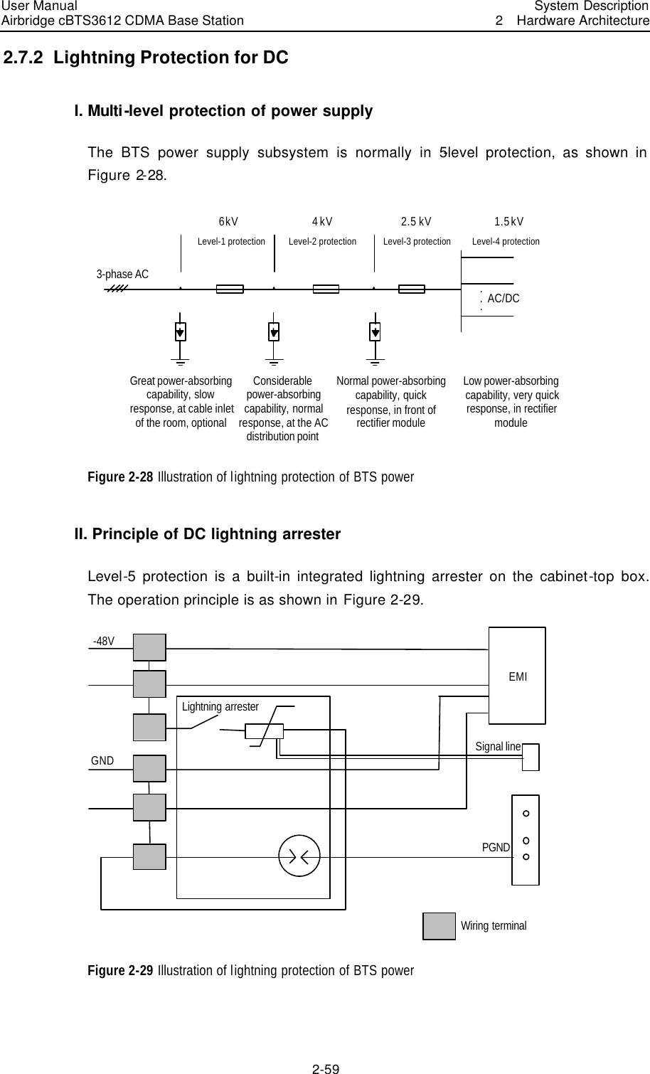
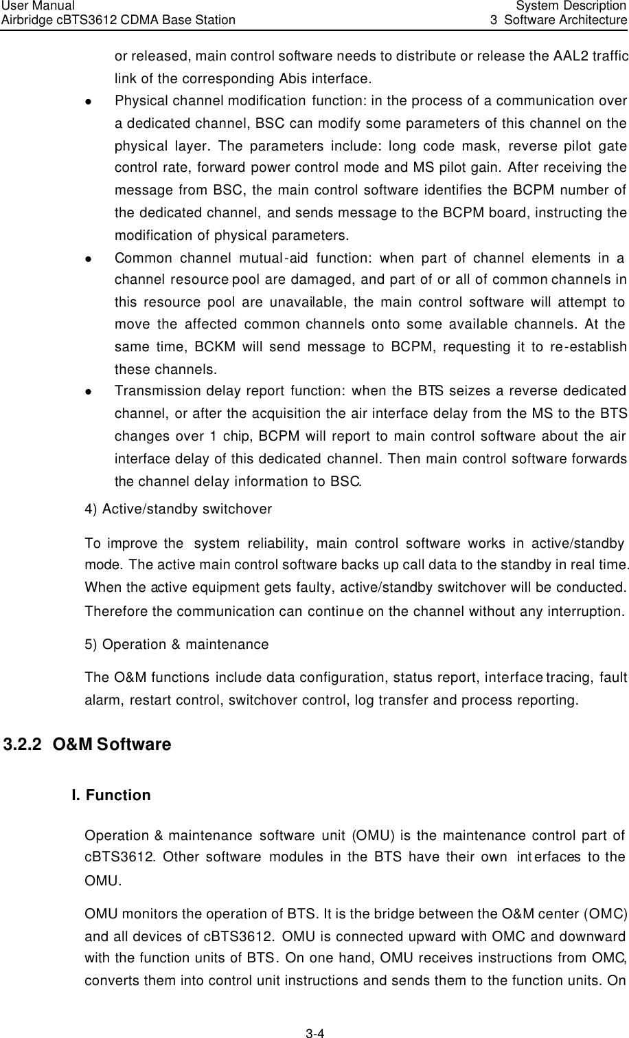
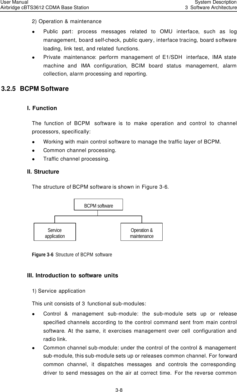
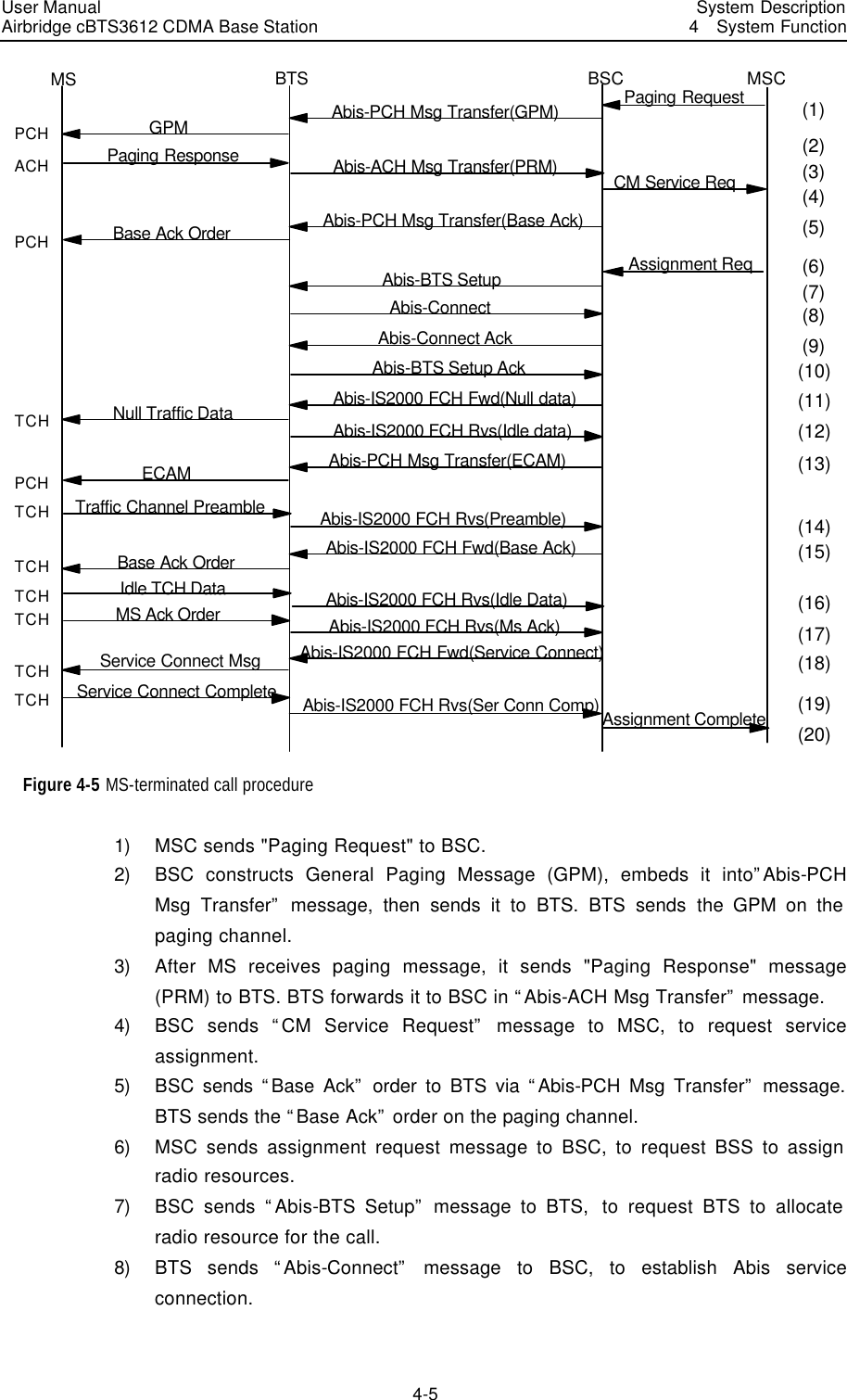
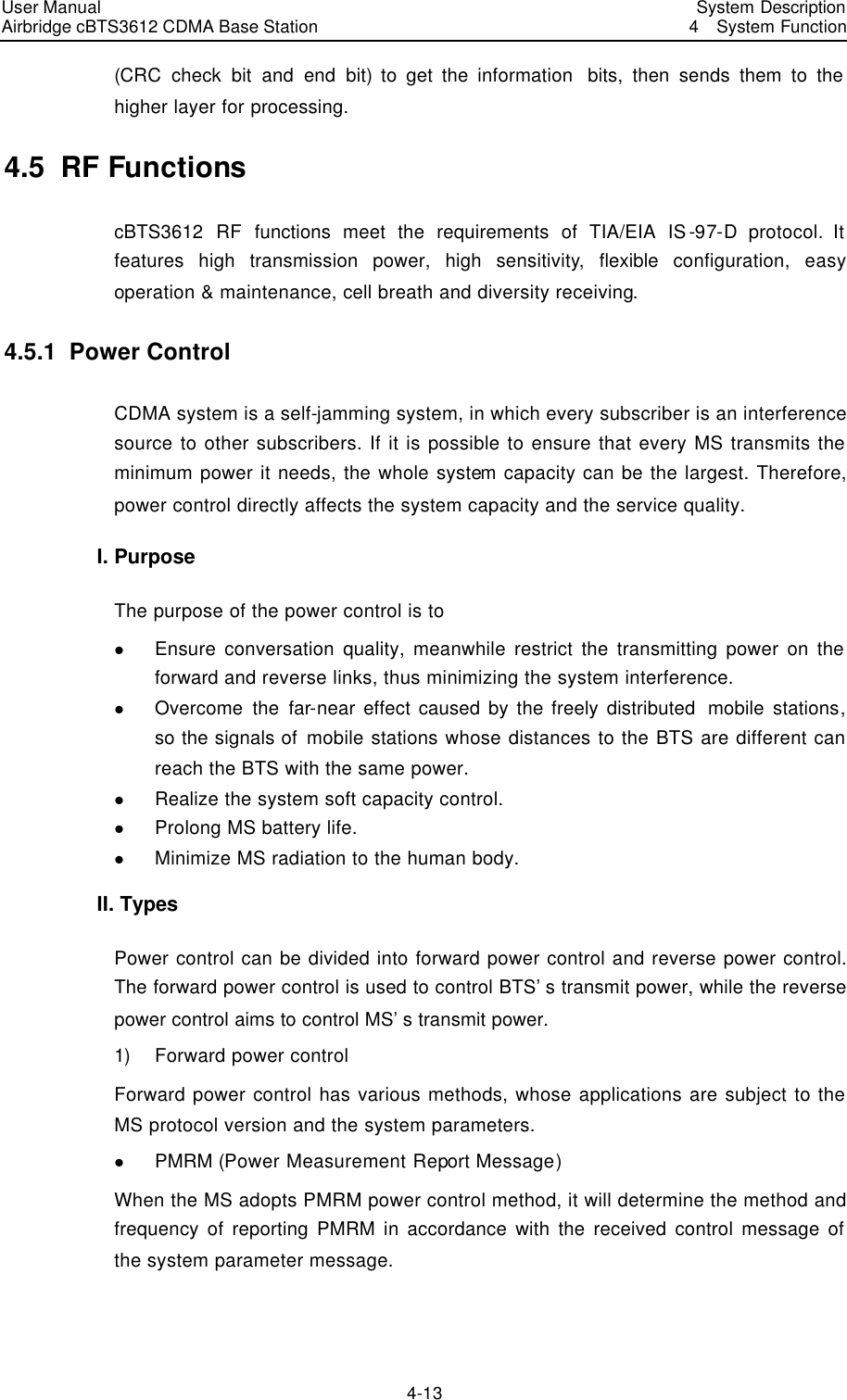
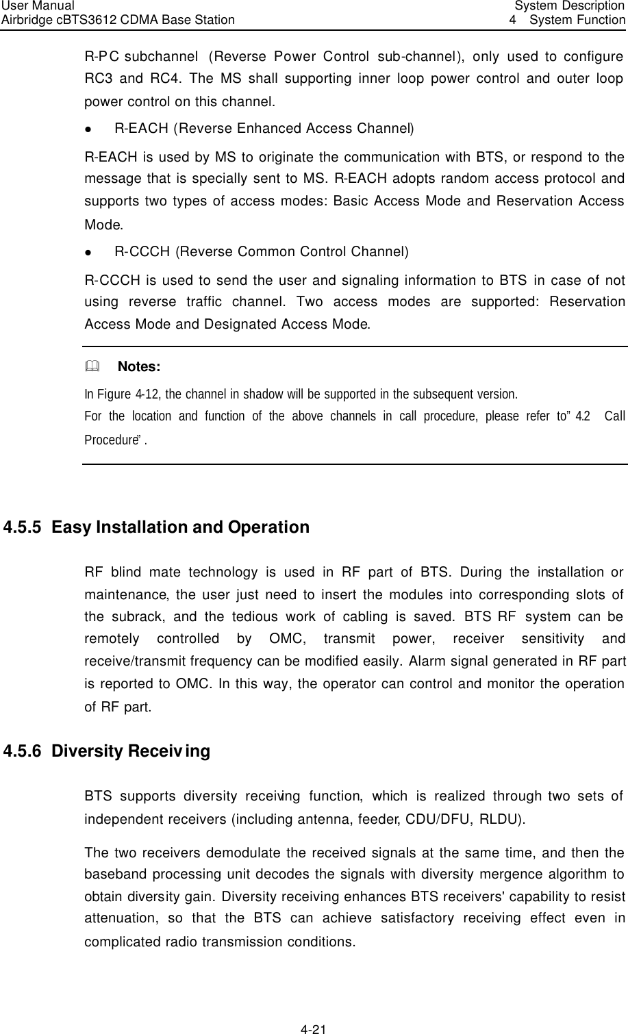
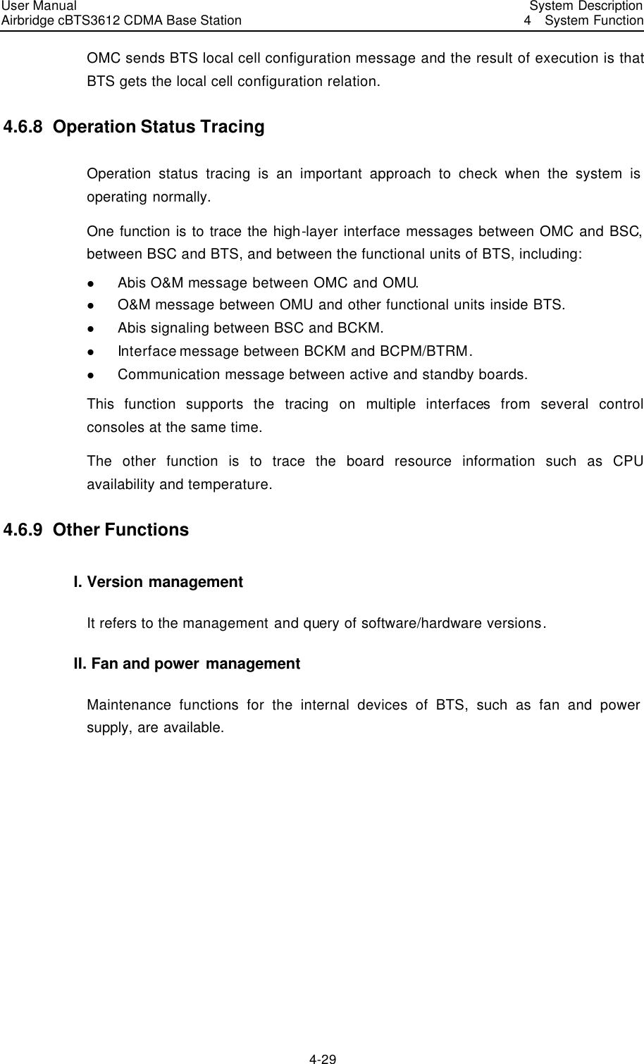
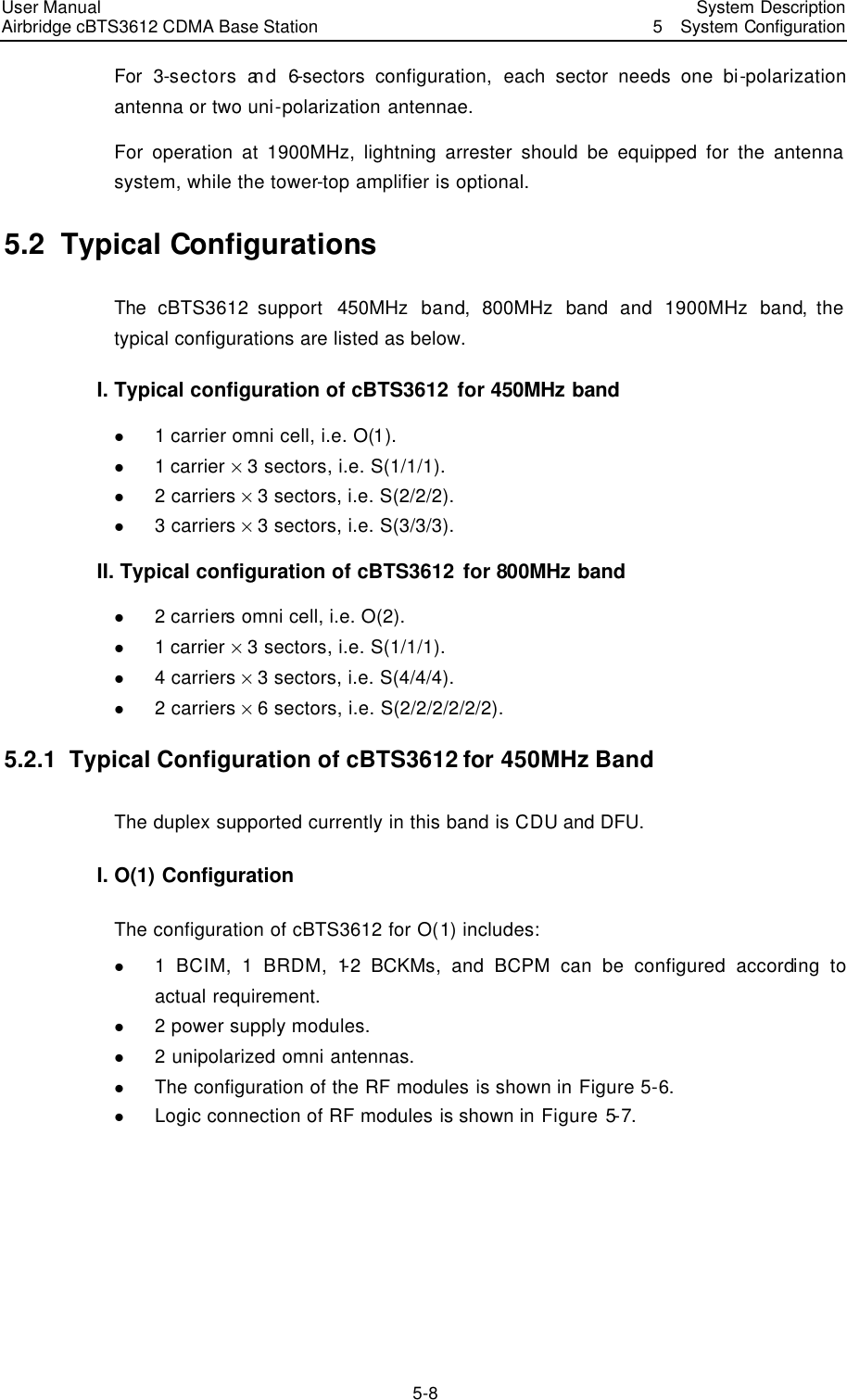
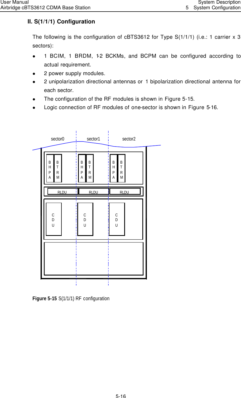
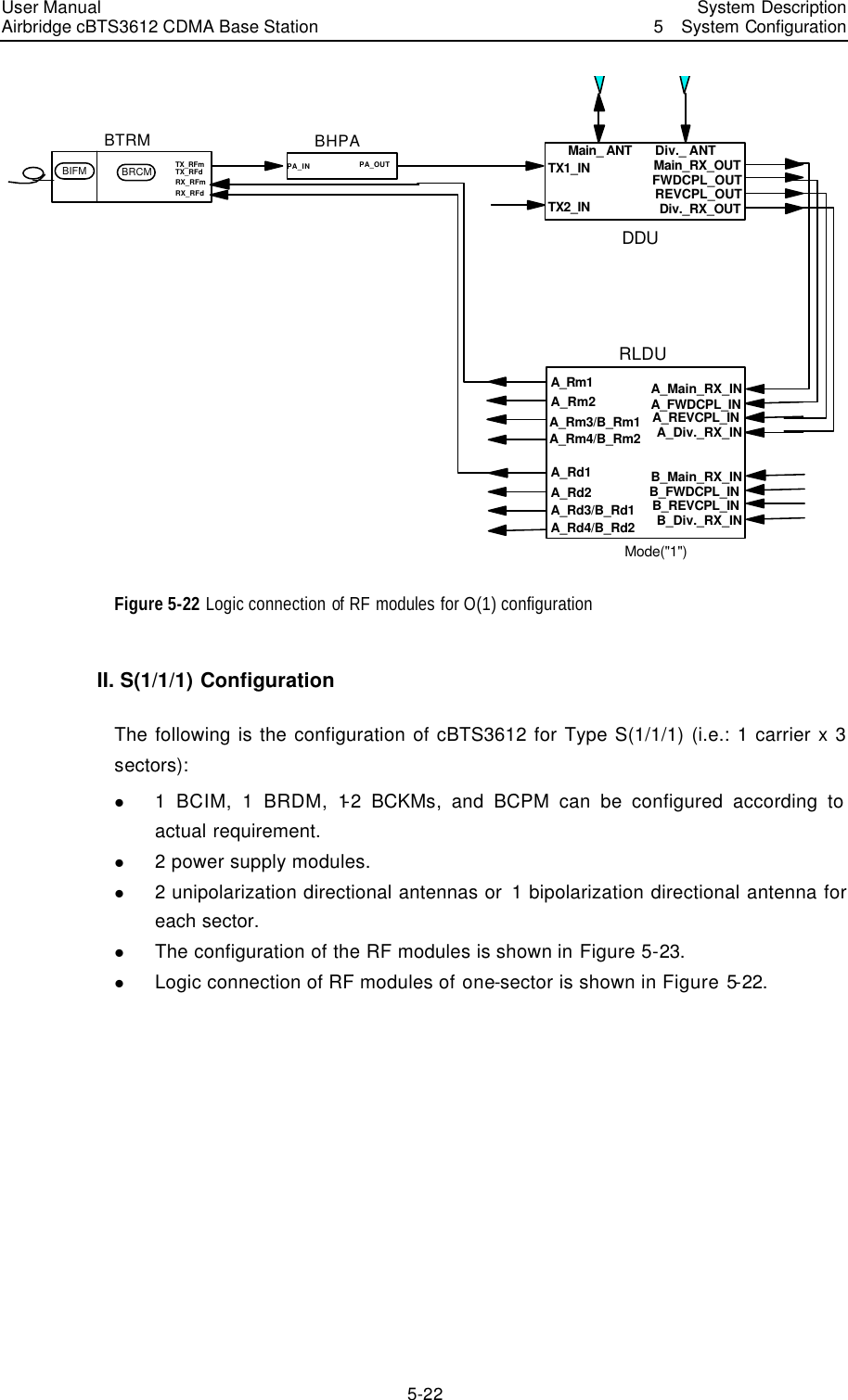
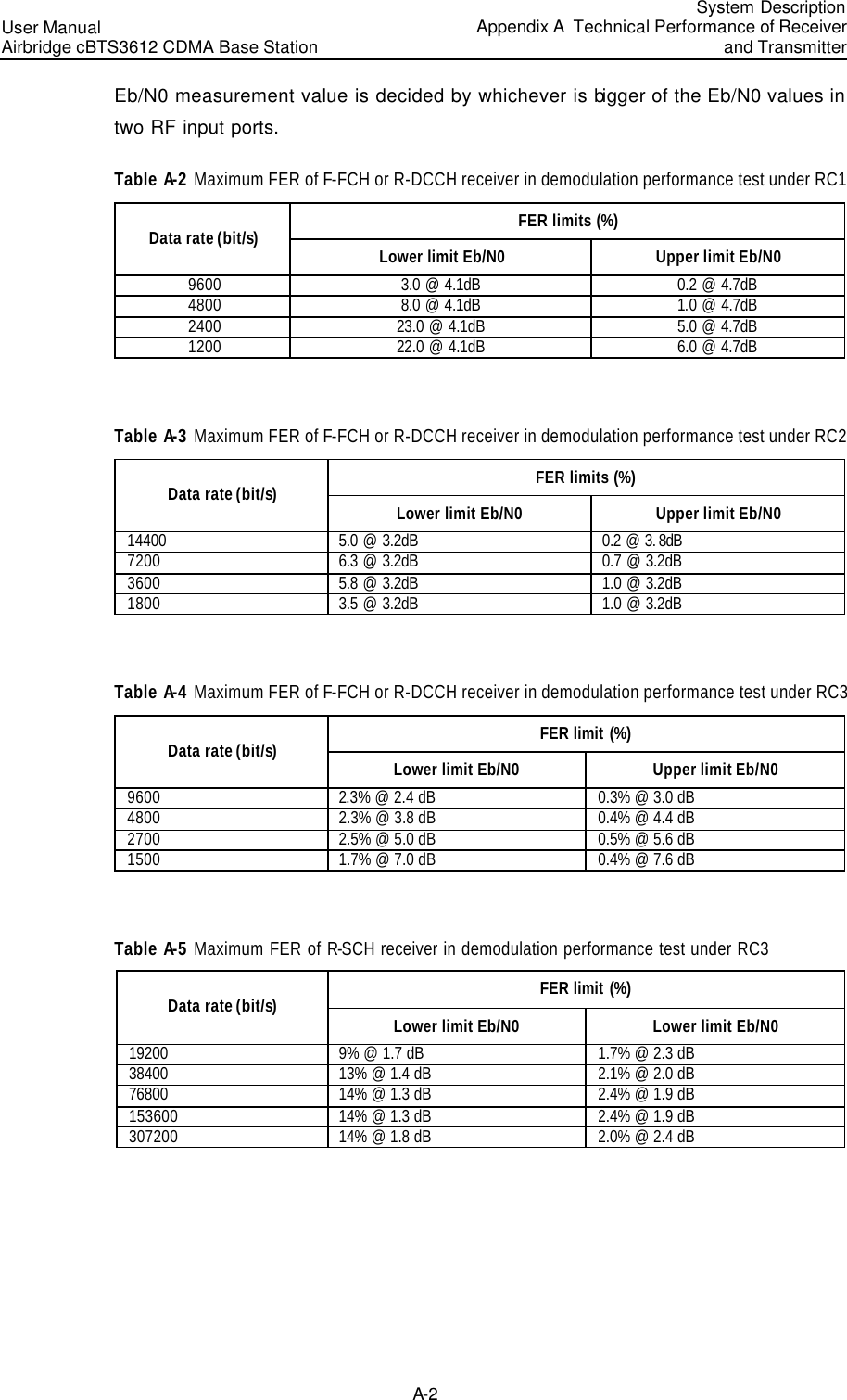
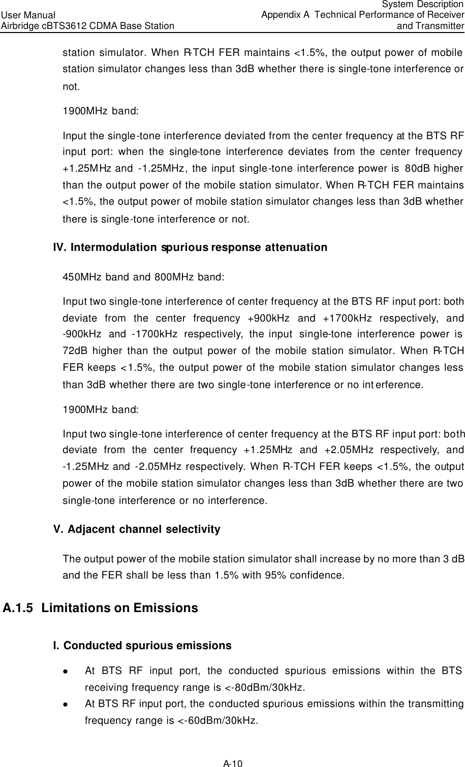
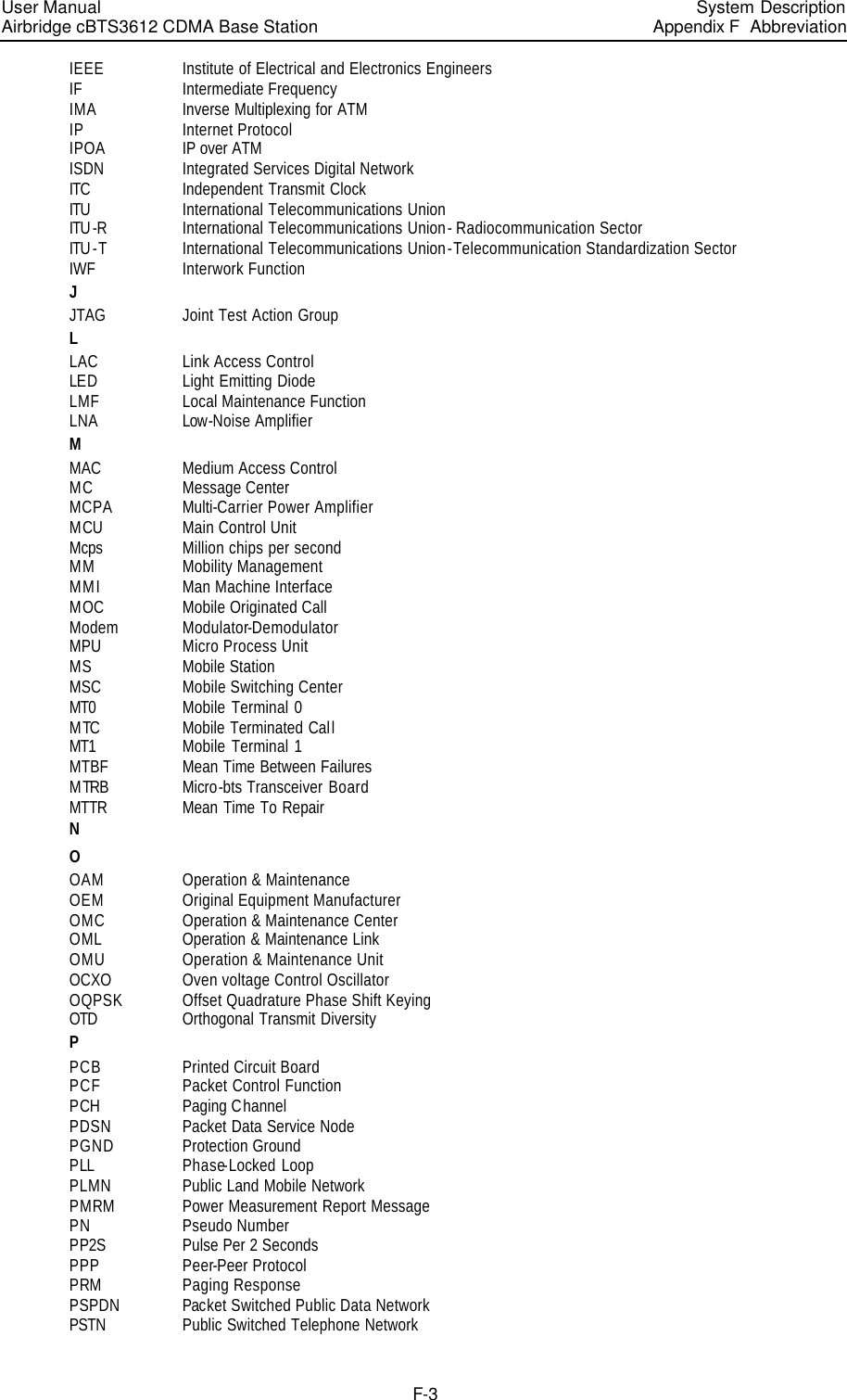
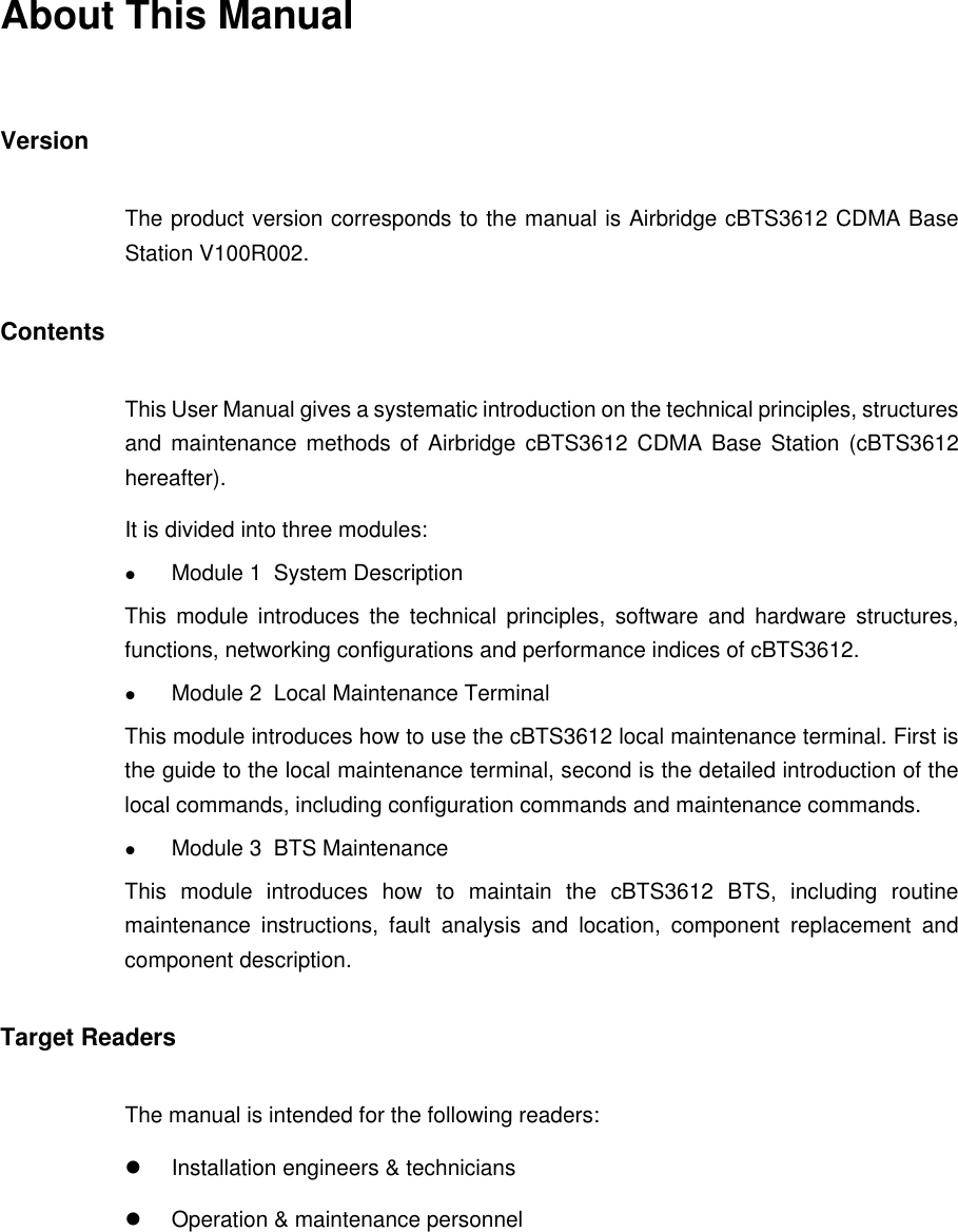
![User Manual Airbridge cBTS3612 CDMA Base Station System DescriptionAppendix B EMC Performance B-1 Appendix B EMC Performance ETSI EN 300 386 Electromagnetic Compatibility and Radio Spectrum Matters (ERM); Telecommunication network Equipment. ElectroMagnetic Compatibility (EMC) Requirements are the EMC standards of telecommunication equipment globally applicable. EMC Performance of BTS comply with ETSI EN 300 386 V1.2.1 (2000-03). They are described in two aspects: EMI (EelectroMagnetic Interference) and EMS (ElectroMagnetic Sensitivity). B.1 EMI Performance 1) Conductive emission (CE) at DC input/output port CE performance indices are listed in Table B-1. Table B-1 CE index at -48V port Threshold (dB µV) Frequency range Average Quasi-peak 0.15 ~ 0.5MHz 0.5 ~ 5MHz 5 ~ 30MHz 56~46 46 50 66~56 56 60 2) Radiated emission (RE) RE performance indices are listed in Table B-2. Table B-2 RE performance requirement Band (MHz) Threshold of quasi-peak (dB µV/m) 30 ~ 1000 61.5 1000 ~ 12700 67.5 & Note: Test place is arranged according to ITU -R 329-7 [1].](https://usermanual.wiki/Huawei-Technologies/CBTS3612-1900.User-Manual/User-Guide-358829-Page-185.png)
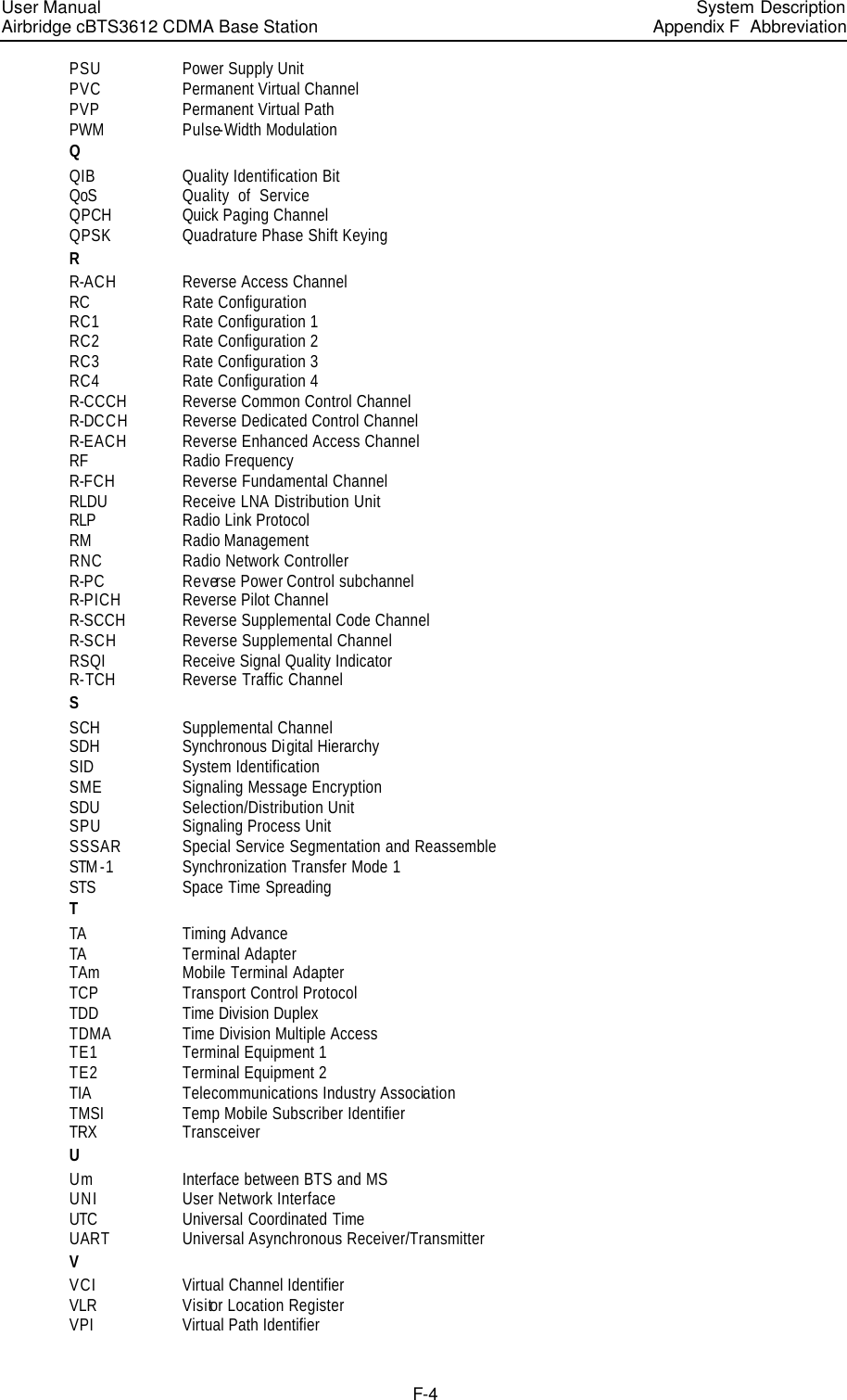
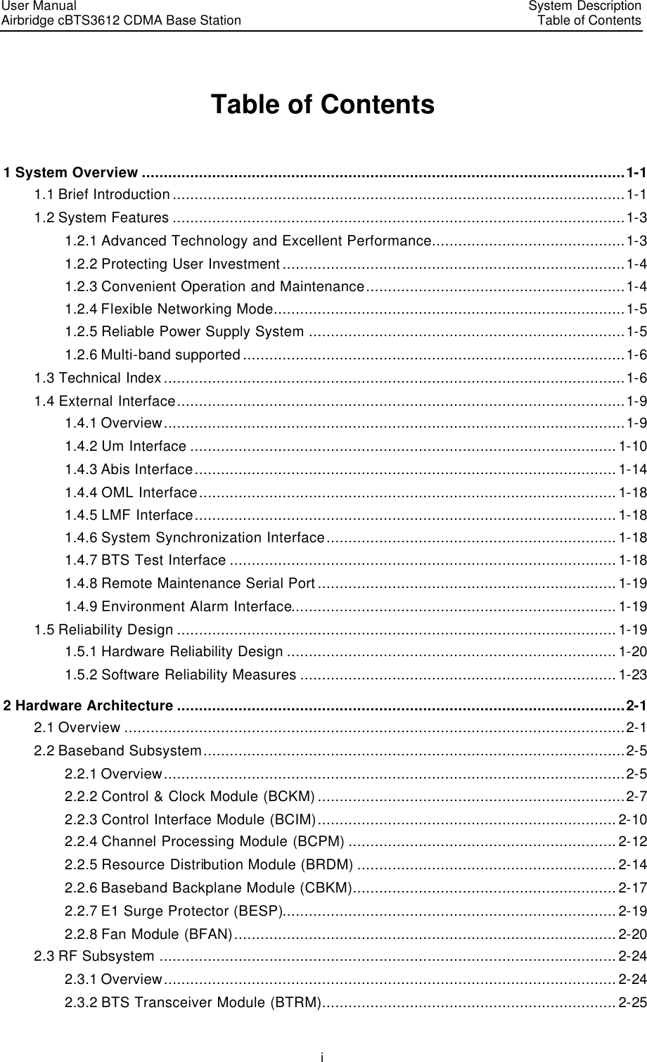
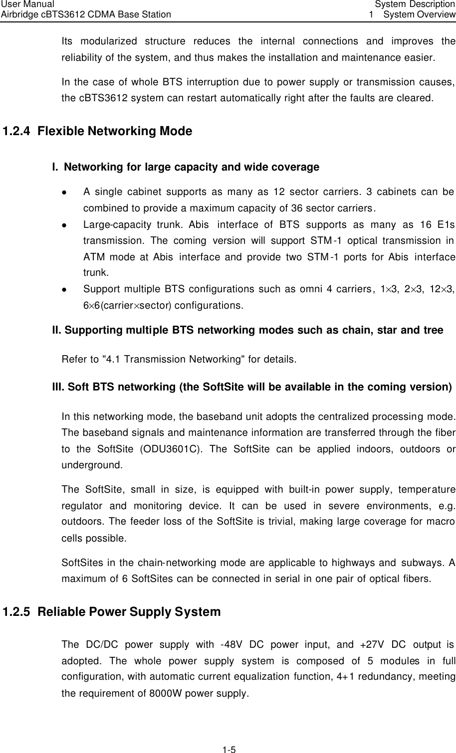
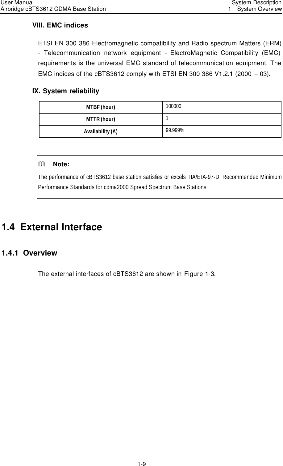
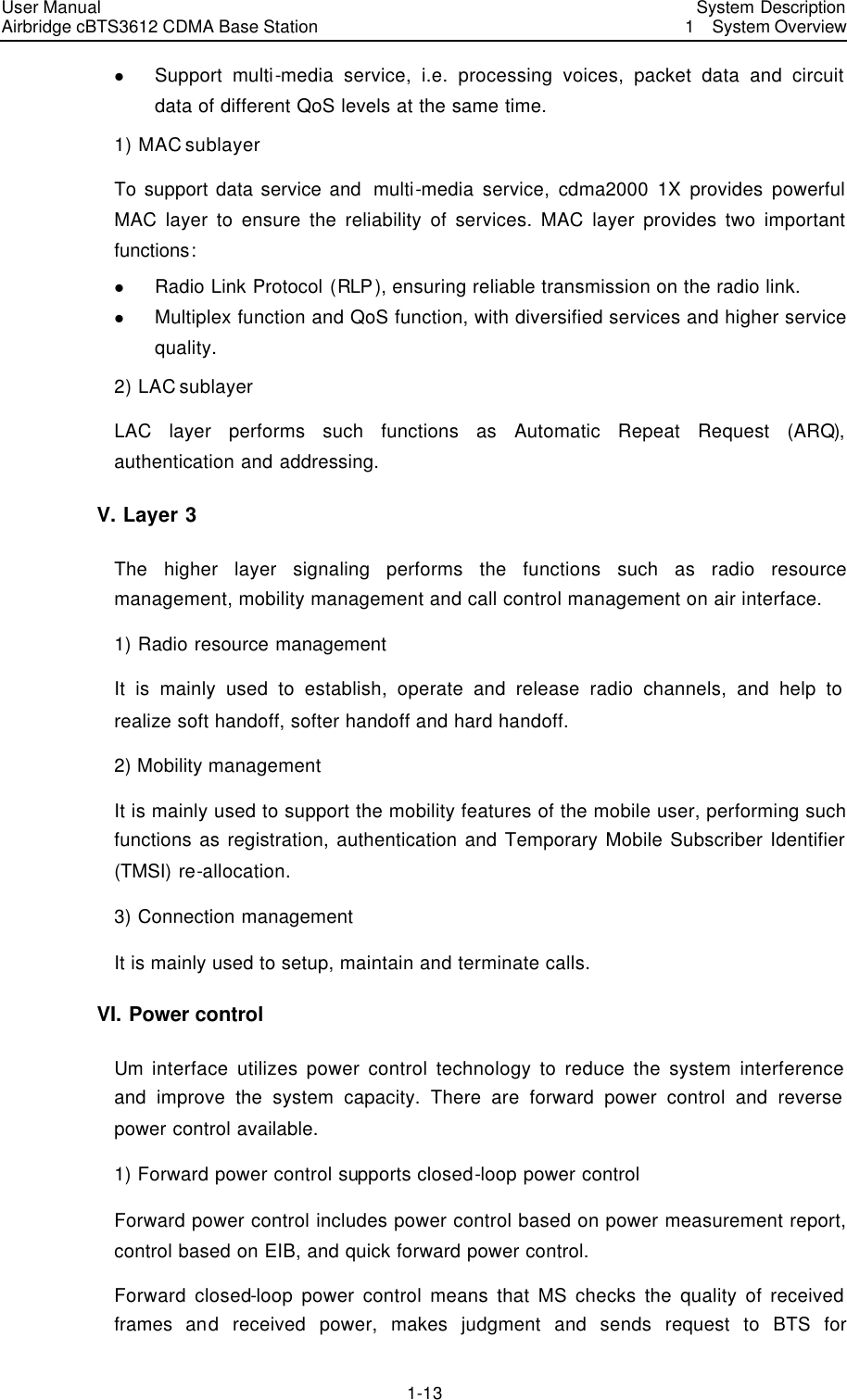
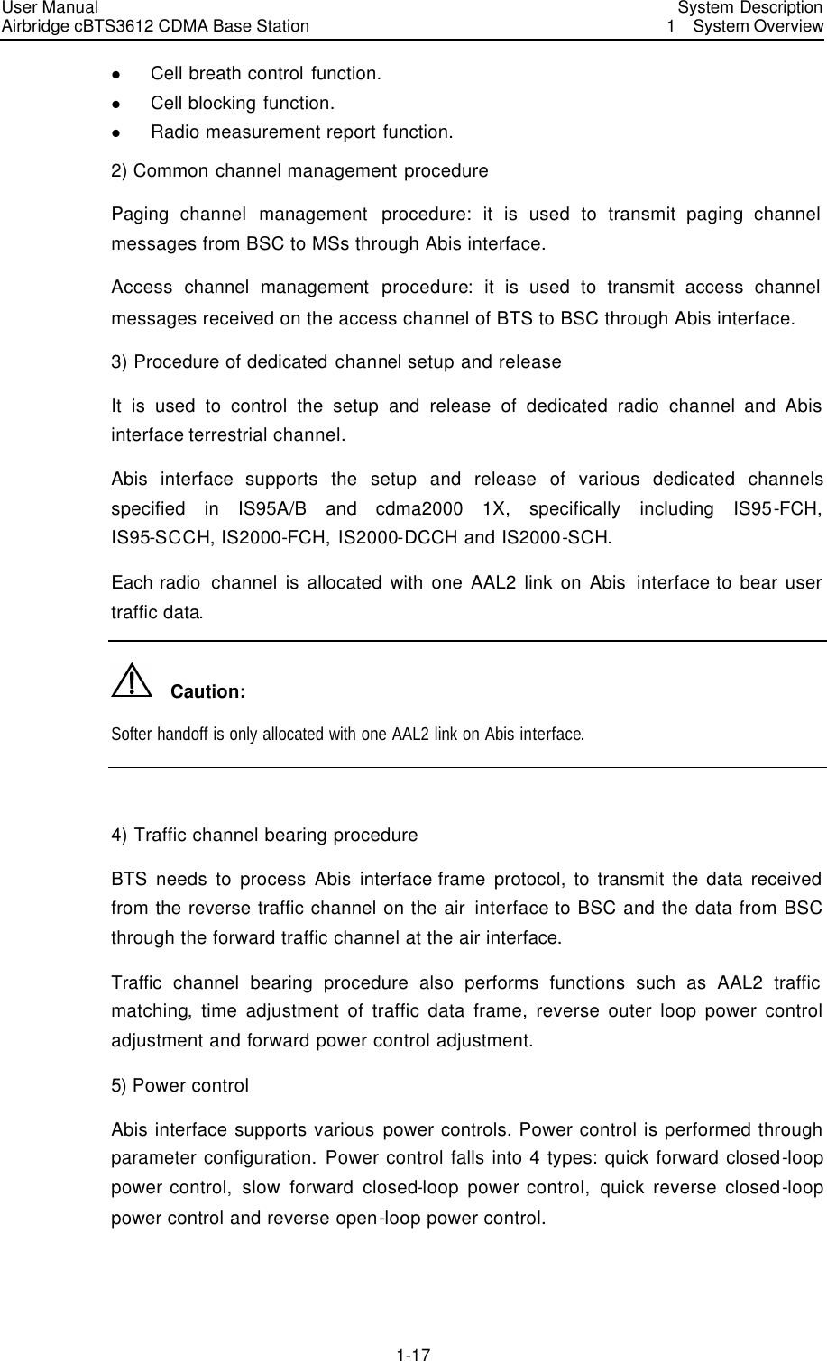
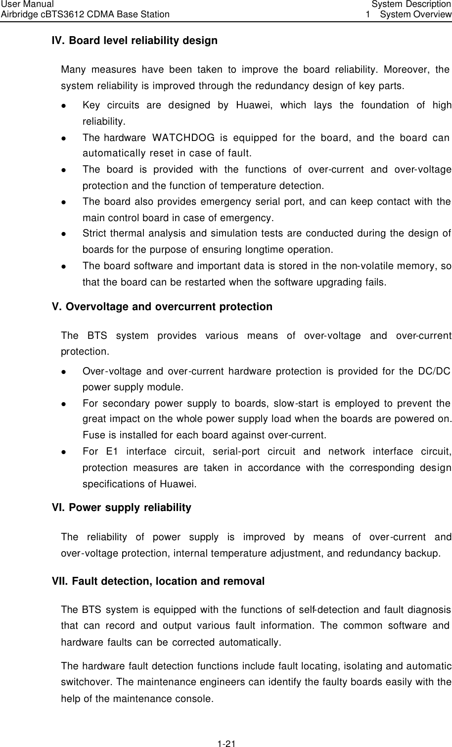
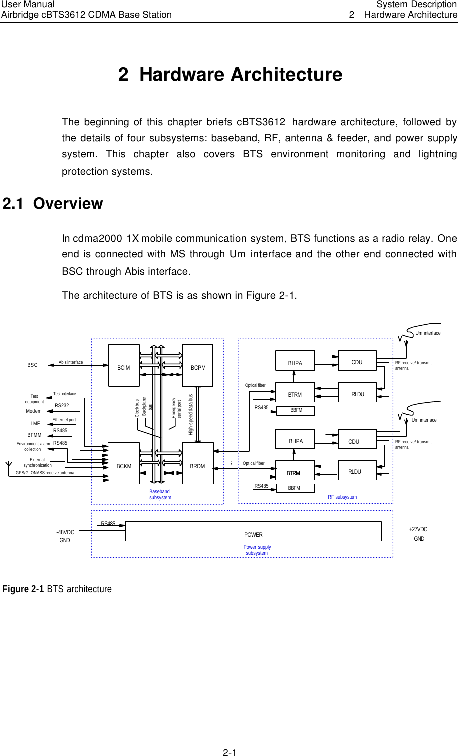
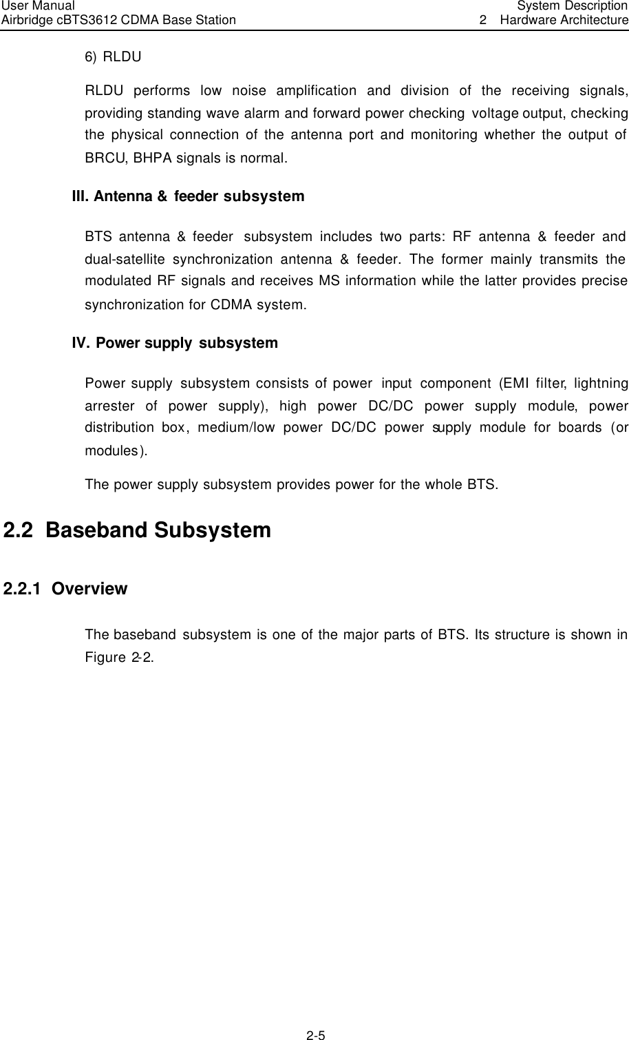
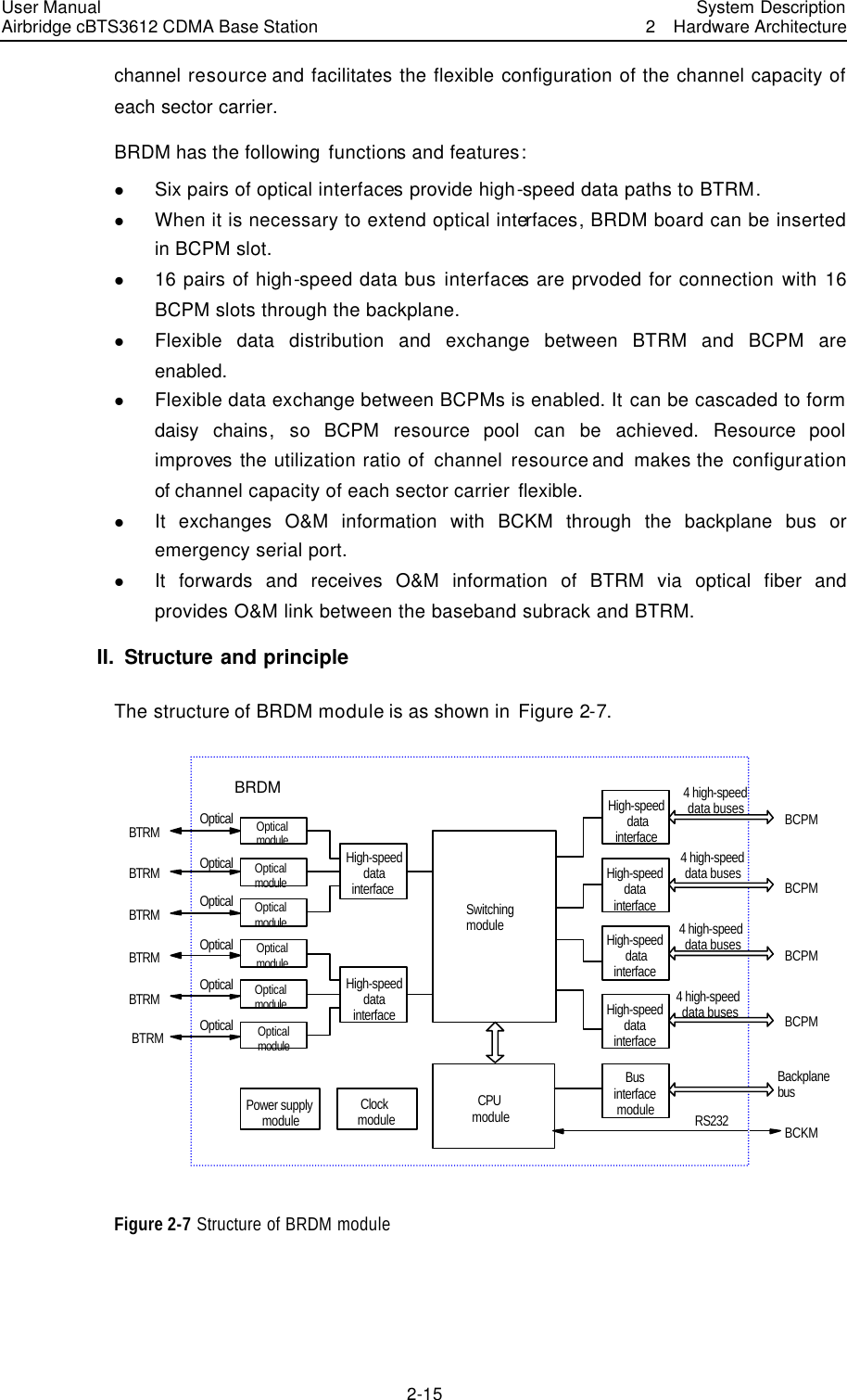
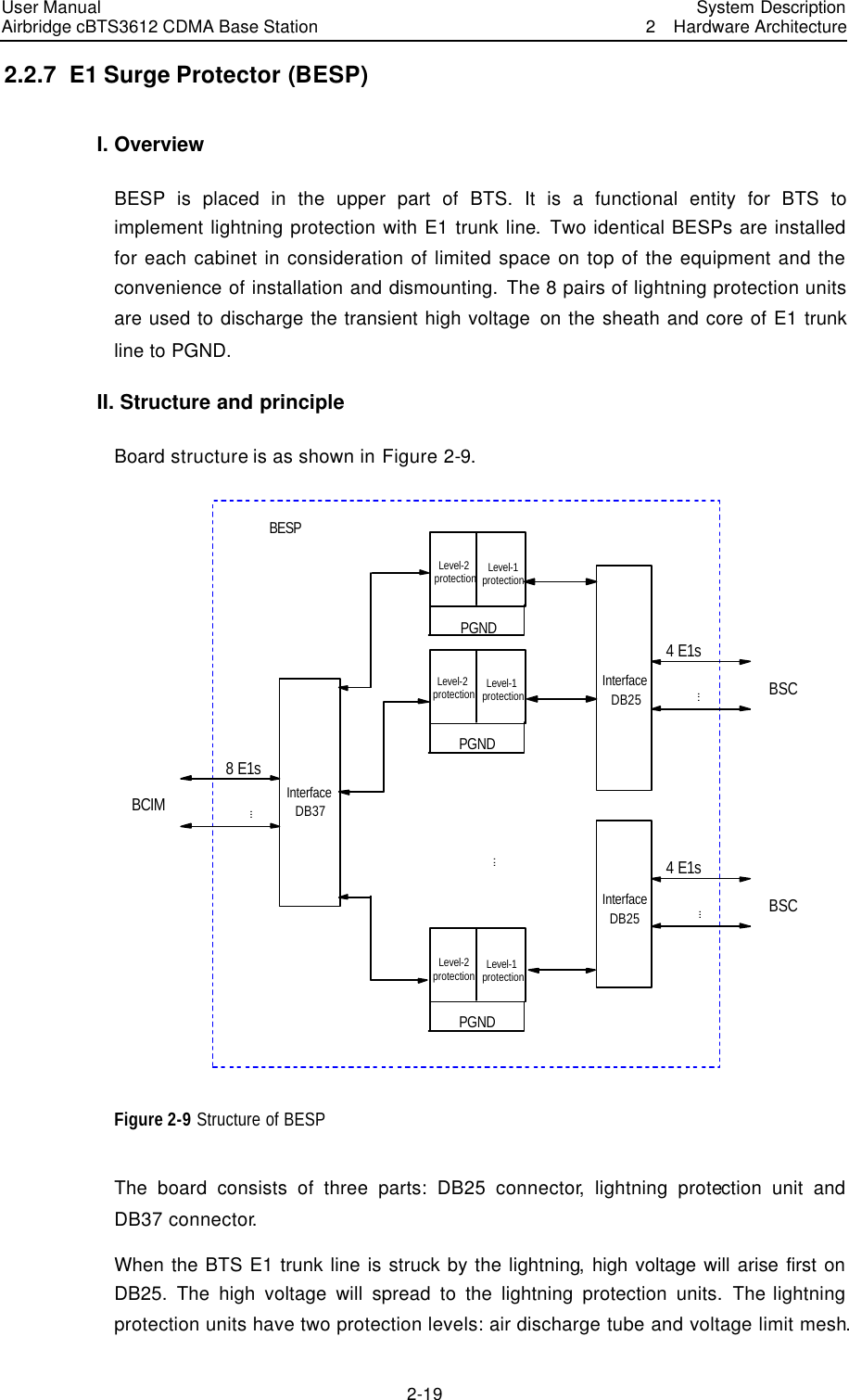
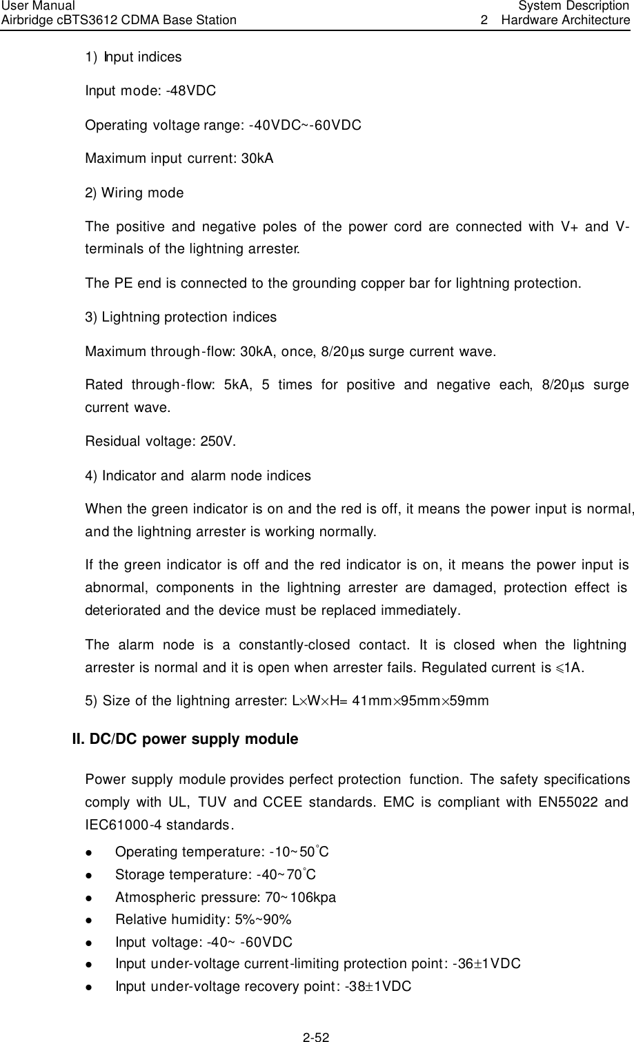
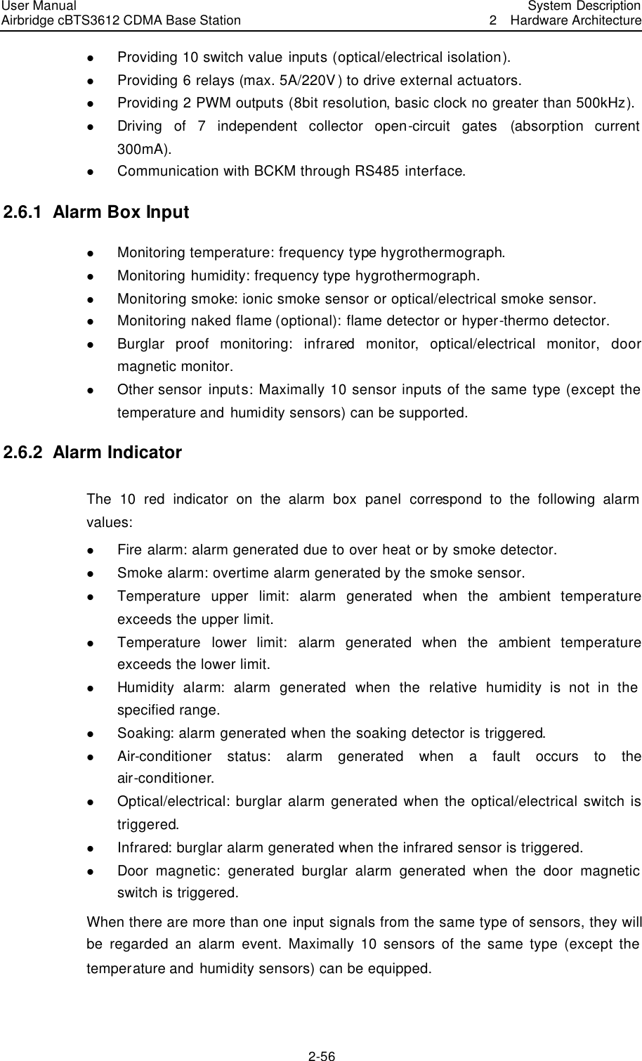
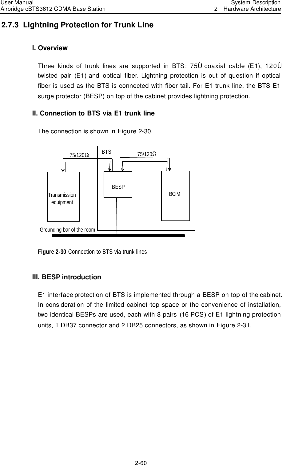
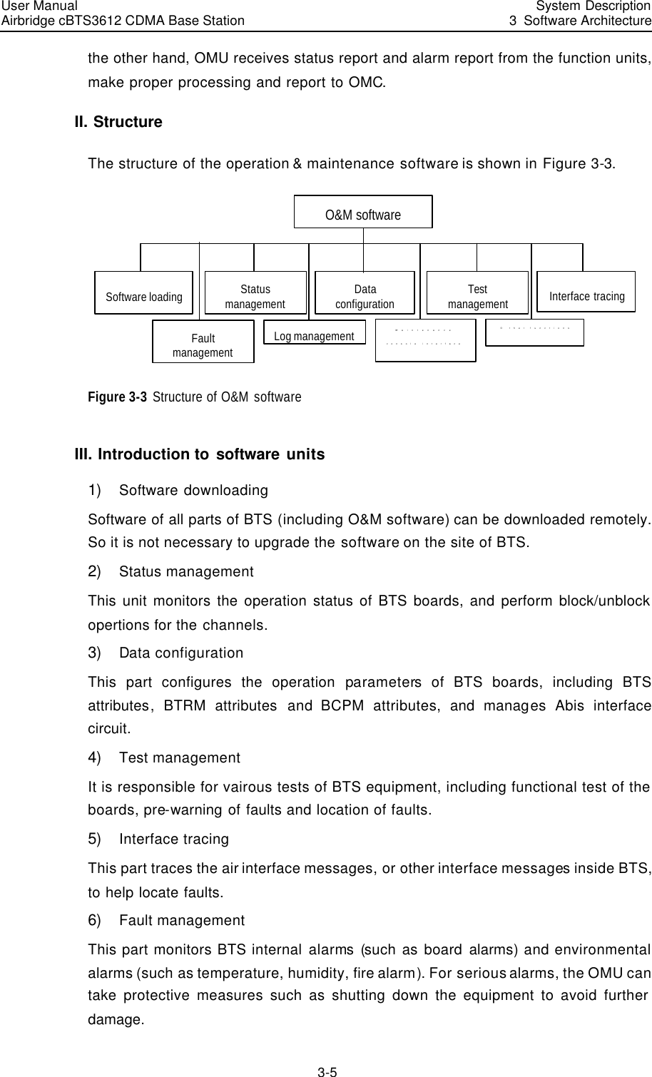
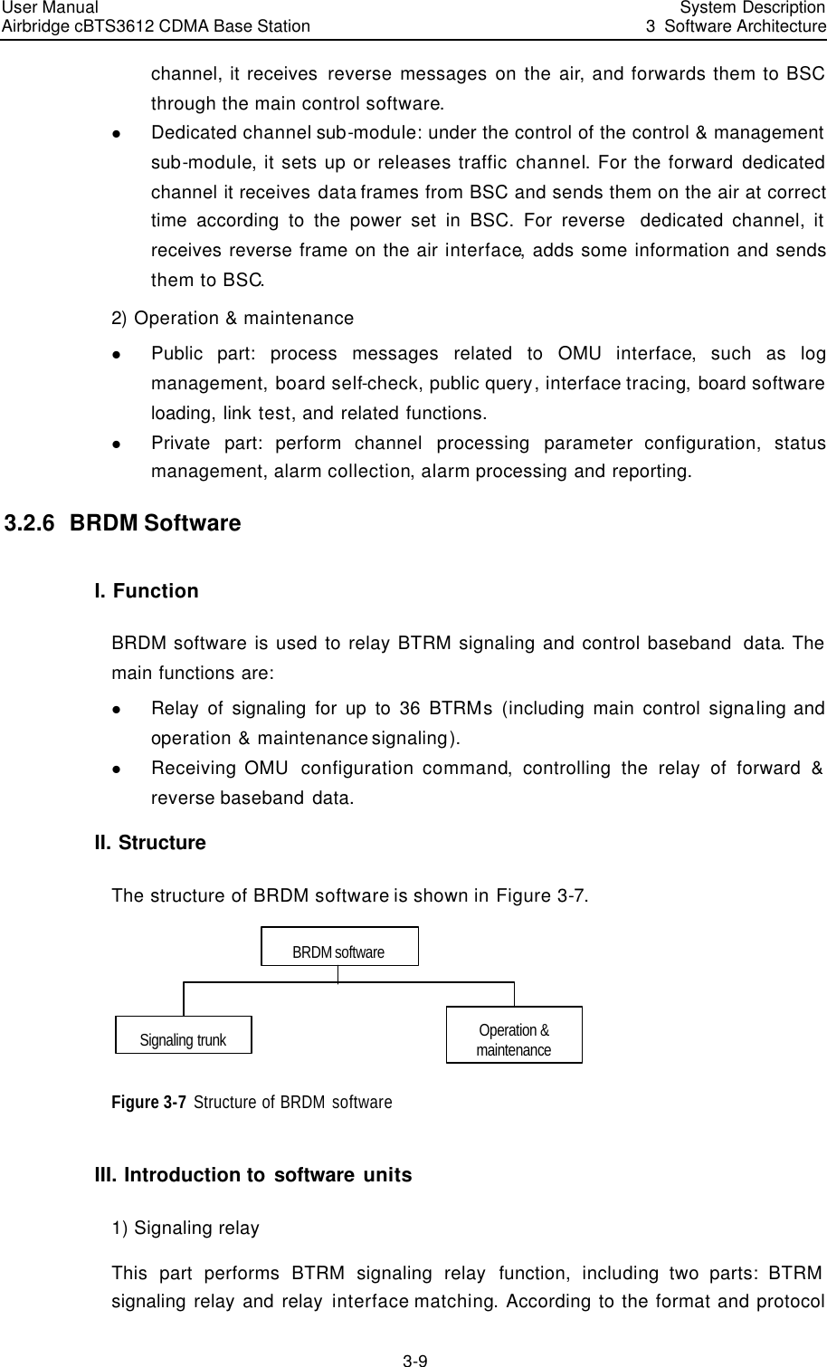
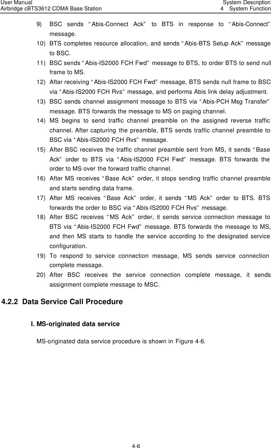
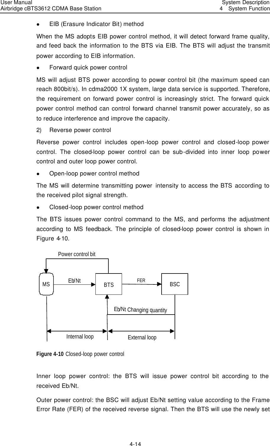
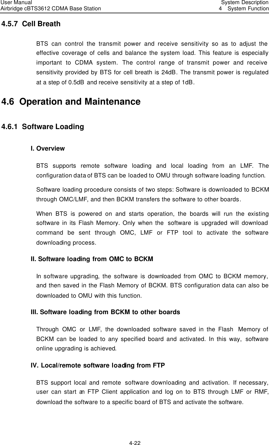
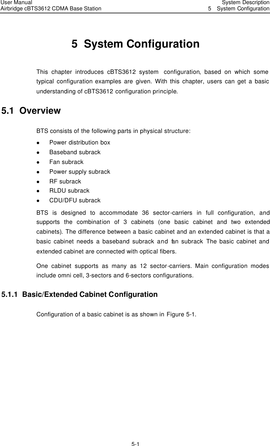
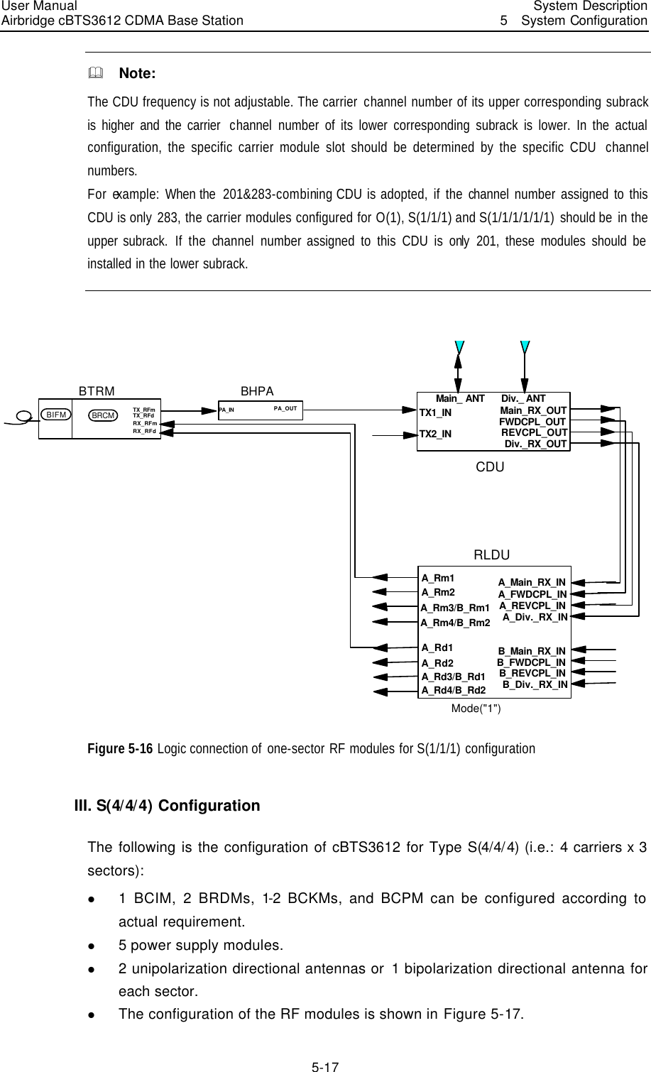
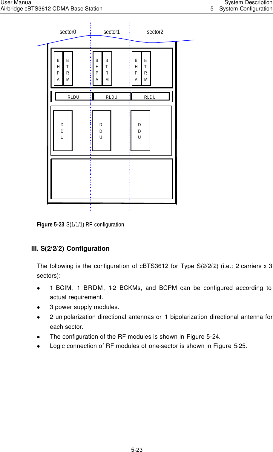
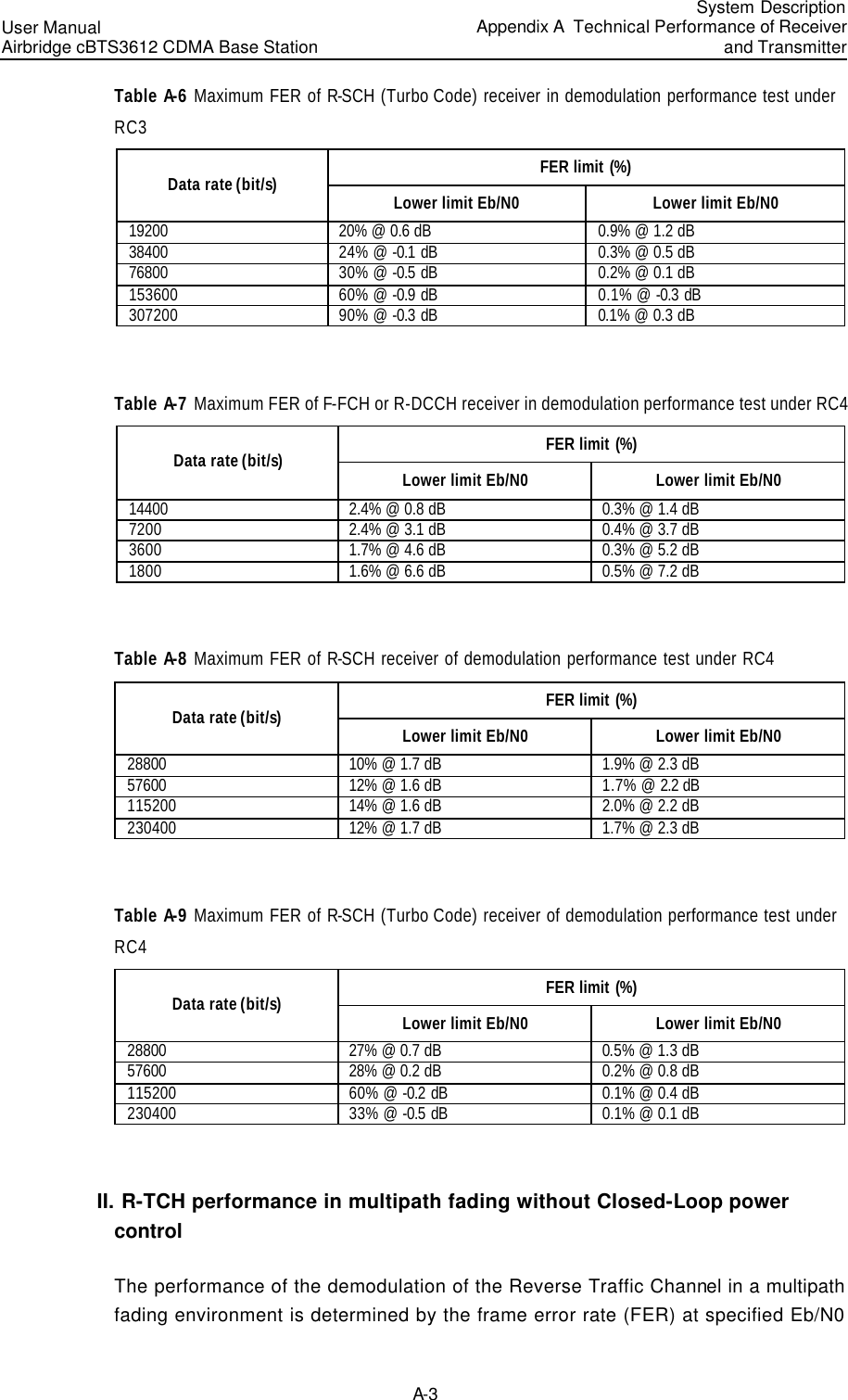
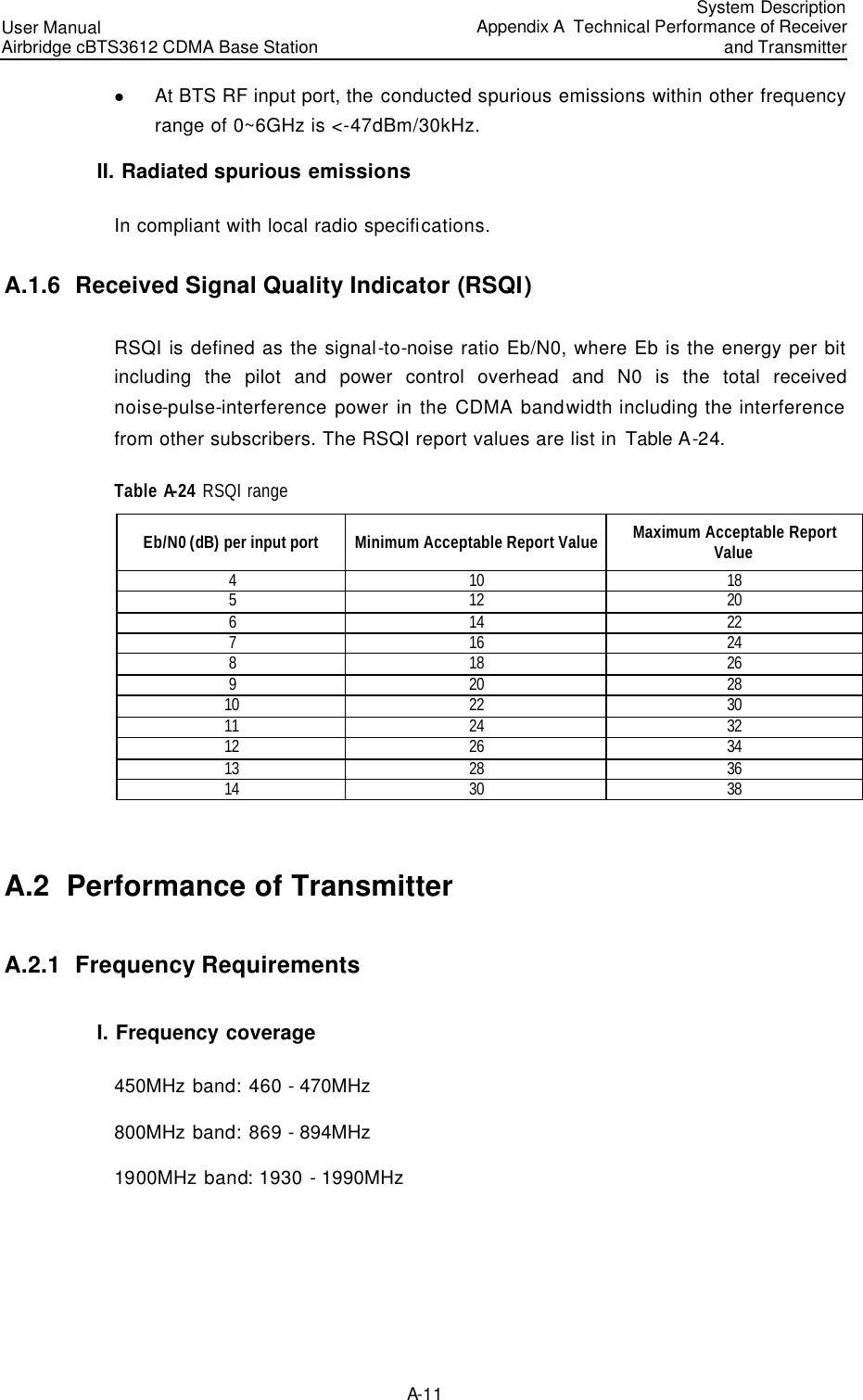
![User Manual Airbridge cBTS3612 CDMA Base Station System DescriptionAppendix B EMC Performance B-2 B.2 EMS Performance 1) R-F anti-electromagnetic interference (80 MHz~1000MHz) Values of RF anti-EMI test are listed in Table B-3. Table B-3 Values of RF anti-EMI test Test port Test level Performance class Whole cabinet 3V/m A & Note: Test method is the same as IEC1000-4-3 [9]. 2) Voltage drop anti-interference Among all test items of EMS, the requirement for resisting continuous interference test is class A and the requirement for resisting transient interference test is class B. Requirement for power drop and level interruption is shown in Table B-4. Table B-4 Requirement for power drop and level interruption Test port Test level Performance class Drop 30% Last for 10ms A Drop 60% Last for 100ms When there is backup power, A When there is no backup power, the communication link need not be maintained. It can be re-created and the user data can be lost. AC port Drop over95% Last for 5000ms When there is backup power, A When there is no backup power, the communication link need not be maintained. It can be re-created and the user data can be lost. & Note: Test method is the same as IEC61000-4-11 [13]. 3) Electrostatic discharge (ESD) Requirement for ESD test level is shown in Table B-5.](https://usermanual.wiki/Huawei-Technologies/CBTS3612-1900.User-Manual/User-Guide-358829-Page-186.png)
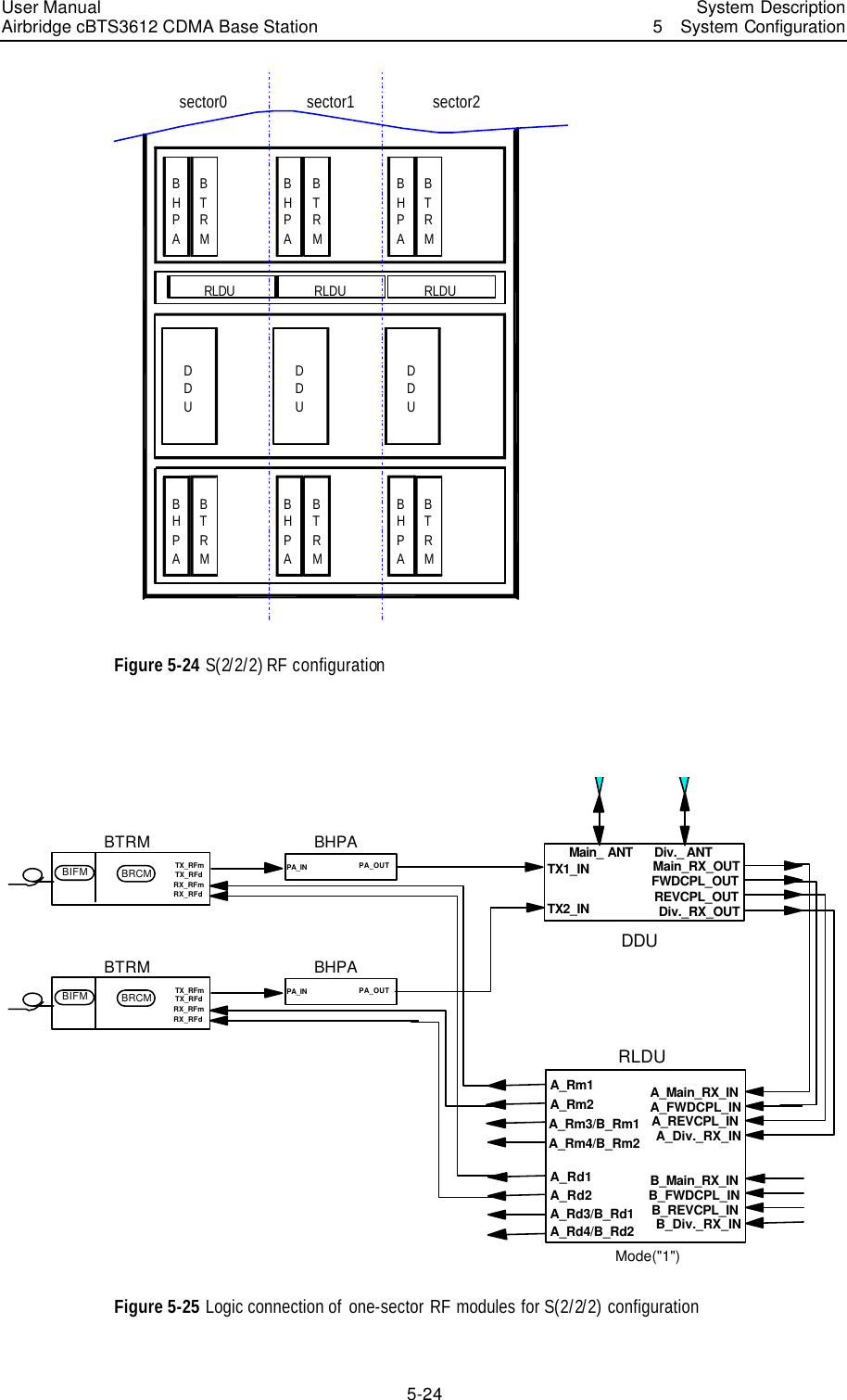
![User Manual Airbridge cBTS3612 CDMA Base Station System DescriptionAppendix B EMC Performance B-3 Table B-5 Requirement for ESD test level Discharge mode Test level Performance class Contact 2kV, 4kV B Air 2kV, 4kV, 8kV B & Note: 1. Test method is the same as IEC 61000-4-2 [5]. 2. ESD should be performed to all exposed surface of equipment to be tested except those to be protected as required by the user's document. 4) RF conductive anti-interference In CDMA equipment, the port where a cable of more than 1 meter may be connected to, including control port, DC input/output port and the input/output port of the connection line when cabinets are combined, should satisfy the requirement for RF conductive anti-interference. Voltage level is shown in Table B-6. Table B-6 Voltage level Test port Voltage level Performance class DC line port AC line port Signal line port and control line port 3V A & Note: Test method is the same as IEC61000-4-6 [9] . 5) Surge For CDMA equipment, the DC power input port, indoor signal line of more than 3 m, control line (such as E1 trunk line, serial port line) and the cable that may be led out to the outdoor should all satisfy the requirement for surge interference level. The test level is shown in Table B-7. Table B-7 Test level Test port Test level Performance class AC port Line~line, 2kV Line~ground, 4kV B Control line, signal line Line~line, 0.5kV Line~ground, 1kV B](https://usermanual.wiki/Huawei-Technologies/CBTS3612-1900.User-Manual/User-Guide-358829-Page-187.png)
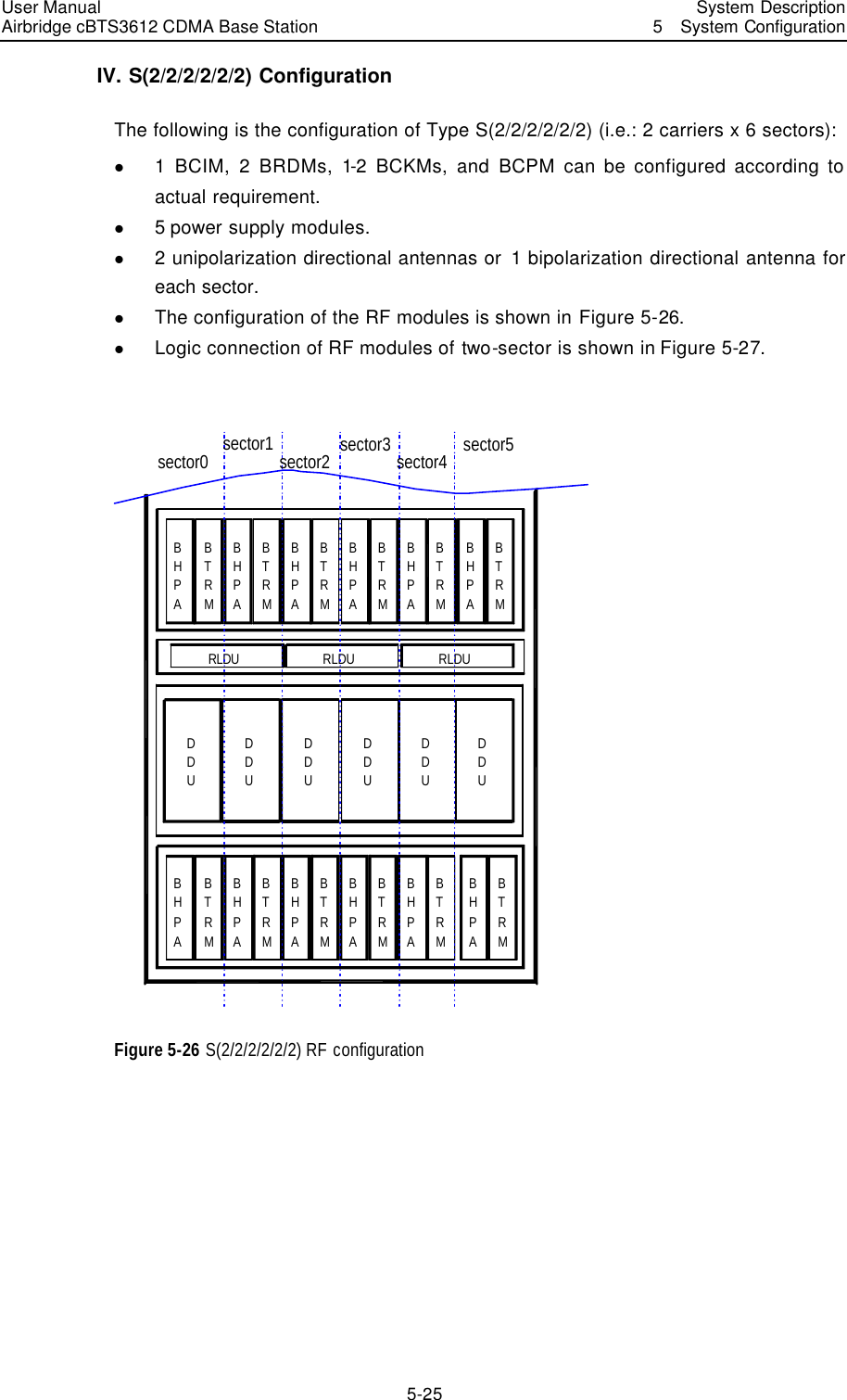
![User Manual Airbridge cBTS3612 CDMA Base Station System DescriptionAppendix B EMC Performance B-4 Test port Test level Performance class Control line, signal line (outdoors) Line~line, 1kV Line~ground, 2kV B & Note: The test method is the same as IEC61000-4-5 [11]. 6) Common-mode fast transient pulse The signal & data line between CDMA cabinets and that connected with other systems (such as E1 trunk line), control line and cable connected to DC input/output port, should be the requirement for fast transient pulse anti-interference level. The threshold value is shown in Table B-8. Table B-8 Threshold value Test port Test level Performance class Signal control line port 0.5kV B DC line input/output port 1kV B AC line input port 2kV B & Note: Performance class A: it means that BTS can withstand the test without any damage and it can run normally in the specified range. There is not any change in the software or data (all data in the storage or the data being processed) related to the tested switching equipment. Equipment performance is not lowered. Performance class B: it means that BTS can withstand the test without any damage. There is no change in the software or the data in storage. Communication performance is lowered a little, but in the tolerance (as defined for different products). The existing communication link is not interrupted. After the test, the equipment can recover to the normal status before the test automatically without any interference of the operator. Performance class C: some functions of BTS are lost temporarily during the test, but they will recover to normal performance in a specific period after the test (normally the shortest time needed for system reboot). There is no physical damage or system software deterioration. Performance class R: after the test, there is no physical damage or fault (including software corruption) with BTS. Protection equipment damage caused by external interference signal is acceptable. When the protection equipment is replaced and the running parameters are re-configured, the equipment can operate normally.](https://usermanual.wiki/Huawei-Technologies/CBTS3612-1900.User-Manual/User-Guide-358829-Page-188.png)
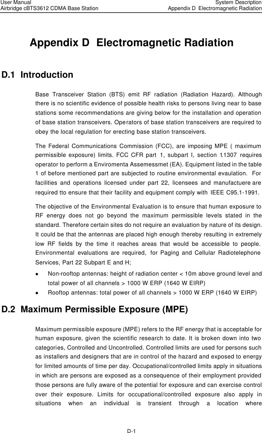
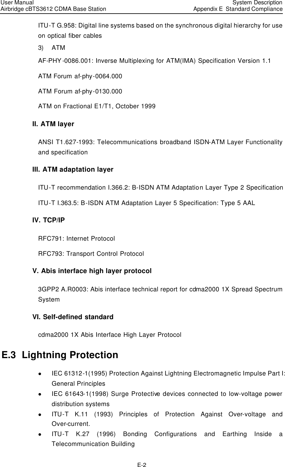
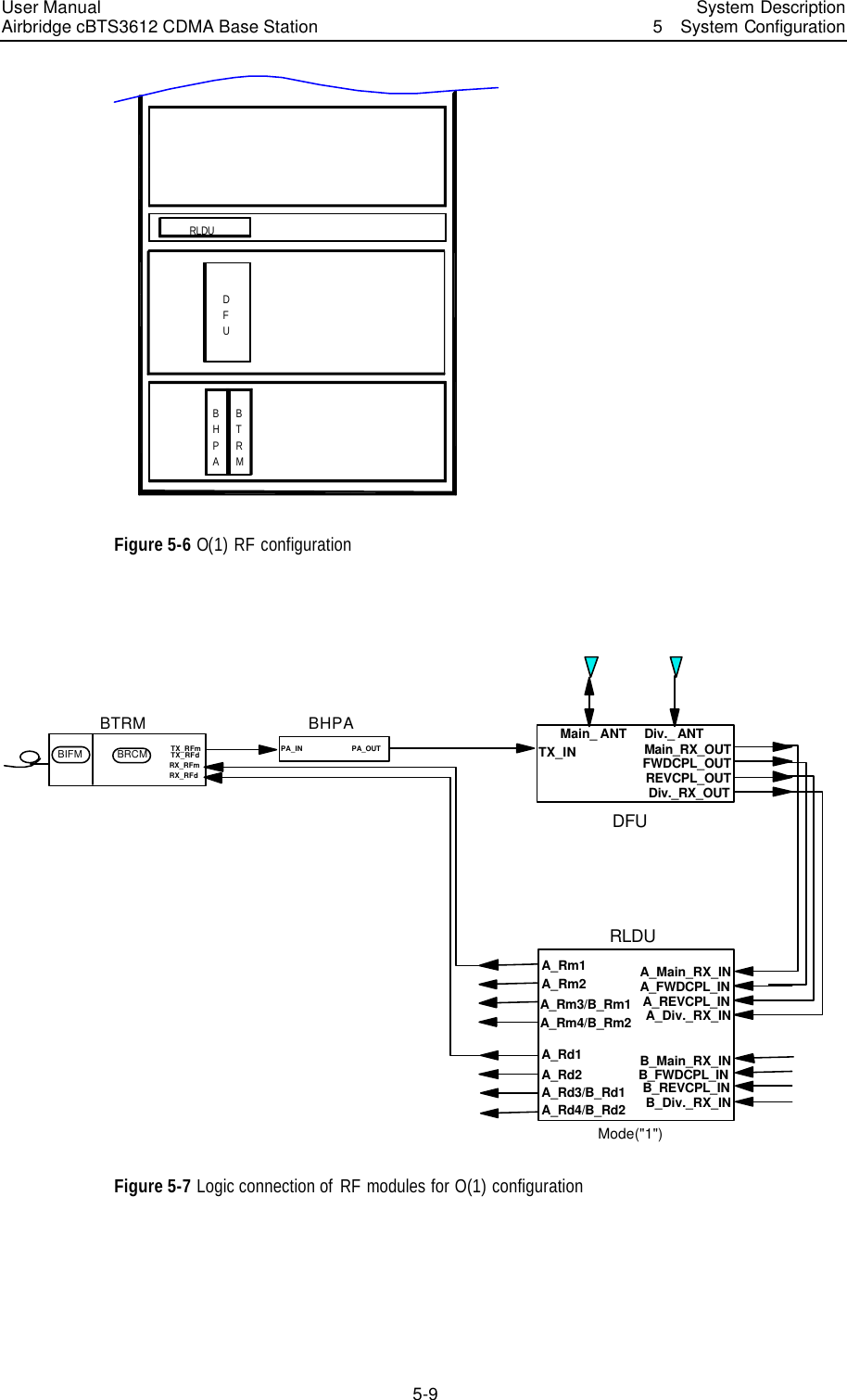
![User Manual Airbridge cBTS3612 CDMA Base Station System DescriptionAppendix D Electromagnetic Radiation D-2 occupational/controlled limits apply provided he or she is made aware of the potential for exposure. Uncontrolled limits are used for general public. General population/uncontrolled exposure apply in situations is which the general public may be exposed, or in which persons that are exposed as a consequence of their employment may not be fully aware of the potential for exposure or can not exercise control over their exposure. The exposure levels can be expressed in terms of power density, electric field strength, or magnetic field strength, as averaged over 30 minutes for the general public and 6 minutes for trained personnel. The exposure criteria is frequency dependent, and a chart covering the range from 3 kHz to 100 GHz can be found in NCRP No.86 (references IEEE C95.1-1991). Below are the limits. Limits for Occupational/Controlled Exposure Frequency Range (MHz) Electric Field Strength (E) (V/m) Magnetic Field Strength (H) (A/m) Power Density (S) (mW/cm2) 0.3-3.0 3.0-30 30-300 300-1500 1500-100,000 614 1842/f 61.4 -- -- .63 4.89/f 0.163 -- -- (100)* (900/f2)* 1.0 f/300 5 Limits for General Population/Uncontrolled Exposure Frequency Range (MHz) Electric Field Strength (E) (V/m) Magnetic Field Strength (H) (A/m) Power Density (S) (mW/cm2) 0.3-3.0 3.0-30 30-300 300-1500 1500-100,000 614 842/f 27.5 -- -- 1.63 2.19/f 0.073 -- -- (100)* (180/f2)* 0.2 f/1500 1.0 Power density S [mW/cm2] for controlled area at 880 MHz 2/9.2300880300][ cmmWMHzfS===](https://usermanual.wiki/Huawei-Technologies/CBTS3612-1900.User-Manual/User-Guide-358829-Page-193.png)
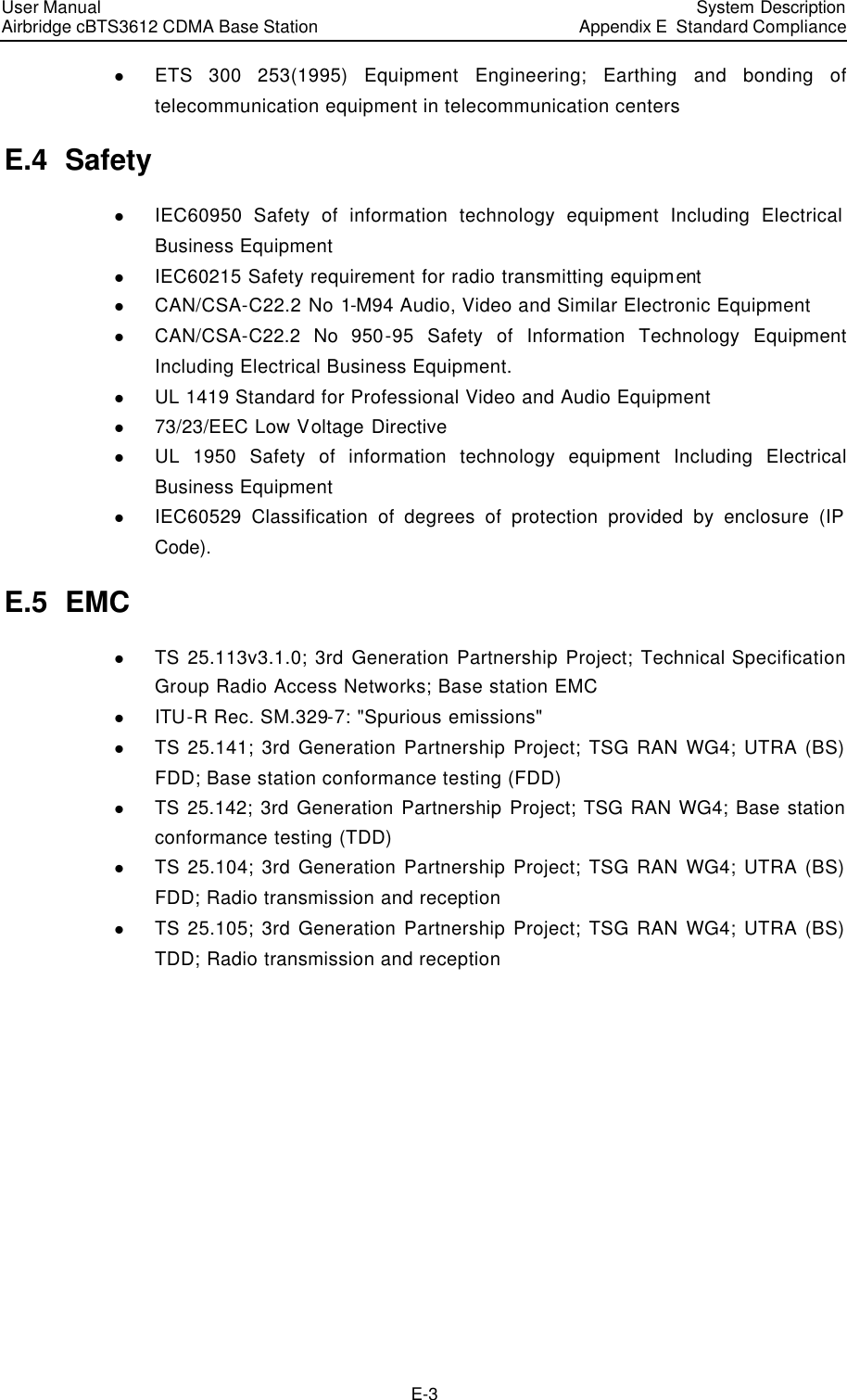
![User Manual Airbridge cBTS3612 CDMA Base Station System DescriptionAppendix D Electromagnetic Radiation D-3 Power density S [mW/cm2] for uncontrolled area at 880 MHz 2/58.015008801500][ cmmWMHzfS=== D.3 Estimation of Exposure to Electromagnetic Fields Below method describes a theoretical approach to calculate possible exposure to electromagnetic radiation around a base station transceiver antenna. Precise statements are basically only possible either with measurements or complex calculations considering the complexity of the environment (e.g. soil conditions, near buildings and other obstacles) which causes reflections, scattering of electromagnetic fields. The maximum output power (given in EIRP) of a base station is usually limited by license conditions of the network operator. A rough estimation of the expected exposure in power flux density on a given point can be made with the following equation. The calcualtions are based on FCC OET 65 Appendix B. π∗∗∗=)(4)(2mrGWPSnumeric Whereas: P = Maximum output power in W of the site G numeric = Numeric gain of the antenna relative to isotropic antenna R = distance between the antenna and the point of exposure in meters D.4 Calculation of Safe Distance Calculations can be made on a site by site basis to ensure the power density is below the limits given above, or guidelines can be done beforehand to ensure the minimum distances from the antenna is maintained through the site planning. SPtGrdπ4**64.1= Whereas: r = distance from the antenna [m]](https://usermanual.wiki/Huawei-Technologies/CBTS3612-1900.User-Manual/User-Guide-358829-Page-194.png)
![User Manual Airbridge cBTS3612 CDMA Base Station System DescriptionAppendix D Electromagnetic Radiation D-4 dG= Antenna gain relative to half wave dipole Pt = Power at the antenna terminals [W] S = power density [W/m2] see also MPE Limits Note: 1mW/cm2 = 10W/m2 D.5 Location of Base Station Antennas Base stations antennas, the source of the radiation, are usually mounted on freestanding towers, with a height up to 30 m or on a tower on the top of buildings or in less cases to the side of the building. Generally the height of the antenna position does not fall below 10 m. The power usually is focused into a horizontal main beam and slightly downward tilted. The remaining power goes into the weaker beams on both side of the main beam. The main beam however does not reach ground level until the distance from the antenna position is around 50 – 200 m. The highest level of emission would be expected in close vicinity of the antenna and in line of sight to the antenna. D.5.1 Exclusion Zones 1) Antenna location should be designed so that the public cannot access areas where the RF radiation exceeds the levels as described above. . 2) If there are areas accessible to workers that exceed the RF radiation exceeds the levels as described above make sure that workers know where these areas are, and that they can (and do) power-down (or shut down) the transmitters when entering these areas. Such areas may not exist; but if they do, they will be confined to areas within 10 m of the antennas. 3) Each Exclusion zone should be defined by a physical barrier and by a easy recognizable sign warning the public or workers that inside the exclusion zone the RF radiation might exceed national limits. D.5.2 Guidelines on Arranging Antenna Locations 1) For roof-mounted antennas, elevate the transmitting antennas above the height of people who may have to be on the roof. 2) For roof-mounted antennas, keep the transmitting antennas away from the areas where people are most likely to be (e.g., roof access points, telephone service points, HVAC equipment). 3) For roof-mounted directional antennas, place the antennas near the periphery and point them away from the building.](https://usermanual.wiki/Huawei-Technologies/CBTS3612-1900.User-Manual/User-Guide-358829-Page-195.png)