Hyundai Electronics Co PIC800 User Manual OperationsMANUAL
Hyundai Electronics Industries Co Ltd OperationsMANUAL
Contents
- 1. System Description
- 2. OperationsMANUAL
OperationsMANUAL

Rev: 1.0
Hyundai Electronics Confidential Proprietary
1
OPERATION MANUAL
FOR
PICO-BTS
IN 800MHZ BAND
Version 1.0
December, 1999

Rev: 1.0
Hyundai Electronics Confidential Proprietary
2
Table of Contents
1. PREFACE 9
2. SAFETY 9
2.1 General Safety Summary 9
2.2 Certification and Compliance 9
3. GETTING STARTED 10
3.1 Product description 10
3.2 Bottom View 11
3.3 Front and Rear Views 12
3.4 Side Views 12
3.5 Inside 13
4. SPECIFICATIONS 14
4.1 Functional Specifications 14
4.1.1 Operating Frequency 14
4.1.2 Interface Specification 14
4.1.2.1 Air Interface 14
4.1.2.2 Equipment Specification 14
4.1.2.3 Backhaul(A-bis) Interface 14
4.2 Performance Specification 15
4.2.1 System Delay 15
4.2.2 Capacity 15
4.3 Electrical Performance 15
4.3.1 Transmitter RF Power 15
4.3.2 Electric Power 15
4.3.2.1 Primary Power 15
4.3.2.2 Battery Backup Power (Optional) 15
4.4 Physical Specifications 16
4.5 Environmental Specifications 16
4.6 Reliability Specifications 16
4.6.1 MTBF 16
4.6.2 Battery Backup time 17
4.6.3 Quality Materials 17
4.6.4 Grounding Requirements 17
4.6.5 Alarm Requirements 17

Rev: 1.0
Hyundai Electronics Confidential Proprietary
3
5. START UP 17
5.1 Installation 17
6. BASIC OPERATION 17
6.1 Power On 17
6.2 GPS Locking 17
6.3 Aging 18
7. BMENU 18
7.1 BMENU Setup 18
7.1.1 Terminal Configuration 19
7.1.2 Notational Conventions 19
7.2 BMENU Invocation 19
7.3 TEST CALL 20
7.3.1 TEST CALL CONFIGURATION menu 20
7.3.1.1 Menu Item: Input IMSI 20
7.3.1.2 Menu Item: Input Slot Mode 20
7.3.1.3 Menu Item: Input Slot Cycle Index 21
7.3.1.4 Menu Item: Input SERVICE OPTION 21
7.3.1.5 Menu Item: Display CONFIGURATION 22
7.3.2 Menu Item: Triggering (Start/Stop) 23
7.3.3 Menu Item: Result Report (Completed & Processing) 24
7.3.4 Menu Item: MARKOV([MS]->BTS->BSC) Mode(default-OFF) 24
7.4 DISPLAY MESSAGE 25
7.4.1 DEVICE CONFIGURATION MESSAGE DISPLAY menu 25
7.4.1.1 DEVICE CONFIGURATION TX MESSAGE DISPLAY MASK menu 25
7.4.1.2 DEVICE CONFIGURATION RX MESSAGE DISPLAY MASK menu 26
7.4.2 CALL CONTROL MESSAGE DISPLAY menu 26
7.4.2.1 TX CCP MESSAGE DISPLAY MASK menu 27
7.4.2.2 RX CCP MESSAGE DISPLAY MASK menu 27
7.4.2.3 TX TRAFFIC CHANNEL ELEMENT (TCE) MESSAGE DISPLAY MASK
menu 28
7.4.2.4 RX TRAFFIC CHANNEL ELEMENT (TCE) MESSAGE DISPLAY MASK
menu 28
7.4.2.5 TX PAGING CHANNEL ELEMENT (PCE) MESSAGE DISPLAY MASK menu
28
7.4.2.6 RX PAGING CHANNEL ELEMENT (PCE) MESSAGE DISPLAY MASK menu
29
7.4.2.7 RX ACCESS CHANNEL ELEMENT (ACE) MESSAGE DISPLAY MASK
menu 29
7.5 CALL STATE FLOW 30
7.5.1 CALL FLOW DISPLAY menu 30
7.5.1.1 CALL ID TRACE menu 30
7.5.1.1.1 Menu Item: ALL CALL FLOW DISPLAY(OFF/ON) 31

Rev: 1.0
Hyundai Electronics Confidential Proprietary
4
7.5.1.1.2 Menu Item: MOBILE(imsi_s1) TRACE 31
7.5.2 Menu Item: Processing Call State Display 32
7.6 RF CHARACTERISTICS 32
7.6.1 Menu Item: RF TEST CALL Start 32
7.6.2 Menu Item: RF TEST CALL Release 34
7.7 LOCAL PARAMETER 34
7.7.1 DISPLAY LOCAL PARAMETER menu 34
7.7.1.1 Menu Item: Display Pilot, Sync and Paging Channel Gains 35
7.7.1.2 Menu Item: Display RFC Tx Gain 35
7.7.2 CHANGE LOCAL PARAMETER menu 35
7.7.2.1 Menu Item: Change Pilot Channel Gain 35
7.7.2.2 Menu Item: Change Sync Channel Gain 36
7.7.2.3 Menu Item: Change Paging Channel Gain 36
7.7.2.4 Menu Item: Change Traffic Channel Gain 36
7.7.2.5 Menu Item: Change RFC Gain 36
7.8 RESOURCE STATUS 37
7.8.1 Menu Item: Display Carrier(BLINK) data 37
7.8.2 DISPLAY CHANNEL CARD DATA menu 37
7.8.2.1 Menu Item: Display Channel Card 38
7.8.2.2 Menu Item: Display Pilot and Sync Channel 38
7.8.2.3 Menu Item: Display Paging Channel 38
7.8.2.4 Menu Item: Display Access Channel 39
7.8.2.5 Menu Item: Display Traffic Channel 39
7.8.2.6 Menu Item: Display Error Rate of Traffic Channel 40
7.8.3 Menu Item: Display Walsh Code 41
7.8.4 Menu Item: Display Power bank 41
7.8.5 Menu Item: Display Using TCE 41
7.9 CDMA Utility 42
7.9.1 Menu Item: Phone Number --> MIN 42
7.9.2 Menu Item: MIN --> Phone Number 42
7.9.3 Hash Randomize menu 43
7.9.3.1 Menu Item: Random CDMA Channel Index 43
7.9.3.2 Menu Item: Random Paging Channel Number 43
7.9.3.3 Menu Item: Random Paging Slot 43
7.9.3.4 Menu Item: Random Access Channel PN 44
8. MAINTENANCE ADVICE 45
8.1 Operation/Configuration Management 45
8.2 Performance Management 45
8.3 Maintenance Management 45
List of Figures
FIGURE 3.2-1 11
FIGURE 3.3-1 12

Rev: 1.0
Hyundai Electronics Confidential Proprietary
5
FIGURE 3.3-2 12
FIGURE 3.4-1 RIGHT SIDE 12
FIGURE 3.4-2 LEFT SIDE 13
FIGURE 3.5-1 13
List of Tables
TABLE 4.1.1-1 PCS OPERATING FREQUENCY 14
TABLE 4.2.1-1 BASE STATION DELAY BUDGET 15
TABLE 4.3.2-1 PRIMARY POWER AC INPUT VOLTAGE RANGE REQUIREMENT 15
TABLE 4.3.2-2 MAXIMUM PRIMARY POWER OUTPUT REQUIREMENT 15
TABLE 4.3.2-3 BATTERY POWER REQUIREMENT 15
TABLE 4.4-1 PHYSICAL SPECIFICATIONS 16
TABLE 4.5-1 ENVIRONMENTAL SPECIFICATIONS 16
TABLE 6.1-1 17
TABLE 6.2-1 18
TABLE 6.2-2 18
TABLE 6.3-1 18
TABLE 7.1.1-1 19
TABLE 7.1.2-1 NOTATIONAL CONVENTIONS 19

Rev: 1.0
Hyundai Electronics Confidential Proprietary
6
Glossary
AC Alternate Current
ACC Analog Common Circuit, replaced by BAC
ACCA Analog Common Card Assembly
ACE Access Channel Element
ACRP Adjacent Channel Power Rejection
ADC Analog To Digital
AGC Automatic Gain Controller
ANT Antenna
BAC Baseband Analog Circuit, replacing ACC
BBU Base Band Unit
BCP BTS Control Processor
BCM BTS Configuration Management
BCOX BTS Call Control Execution
BDAX BCP Data Access Execution
BDC Baseband Digital Card
BDIAX BTS Diagnostic Execution
BDTU BTS Diagnostic & Test Unit
BFMX BTS Fault Management Execution
BIH Backhaul Interface Handler - Software
BIU Backhaul Interface Unit
BMEA BCP Measurement
BLINK BTS Link
BPF Band Pass Filter
BPLX BCP Processor Loader Execution
BRAX BTS Resource Allocation Execution
BRMX BTS Resource Management Execution
BS Base Station
BSC Base Station Controller
BSHX BTS Status Handler Execution
BSM Base Station Manager
BTS Base Transceiver System
BW Band Width
CAI Common Air Interface
CCC Channel Card Common, replaced by CEC
CCP Call Control Processor
CDIAX CCP Diagnostic Execution
CDMA Code Division Multiple Access
CDMX Configuration Data Management Execution
CE Channel Element
CEC Channel Element Controller, replacing CCC
CFMX CCP Fault Management Execution
CMEA CCP Measurement
CPLX CCP Processor Loader Execution
CRAX CCP Resource Allocation Execution
CSHX CCP Status Handler Execution
CSM Cell Site Modem
DAC Digital to Analog Converter
DC Direct Current
DCS Digital Cellular System
DD Detailed Design
DDS Direct Digital Synthesis
DM Diagnostic Monitor
DU Digital Unit

Rev: 1.0
Hyundai Electronics Confidential Proprietary
7
EMI Electrical Magnetic Interference
FA Frequency Allocation
FIFO First-In-First-Out
FPGA Field Programmable GateArray
GPIO General Purpose Input / Output
GPS Global Positioning System
HDLC High Level Data Link Control
HLD High Level Design
IIn-Phase
IF Intermediate Frequency
IMC Inter Module Communication
IMCB Inter Module Communication Bus
IMCH Inter Module Communication Handler
IPC Inter Processor Communication
LCIN Local CCP Interconnection Network
LED Light Emitting Diode
LNA Low Noise Amplifier
LO1 Local Oscillator 1
LO2 Local Oscillator 2
LPA Linear Power Amplifier
LPF Low Pass Filter
MFP Multi-Function Peripheral
MLNK MSC Link
MMI Man Machine Interface
MRB Monitor/Report Block
MS Mobile Station
MSC Mobile Switching Center
MSPS Mega Sample Per Second
MTBF Mean Time Between Failures
MUX Multiplexer
MVIP Multiple Vendor Integrated Protocol
OC Overload Controller
OPAID Operation AID
PA Power Amplifier
PCI Peripheral Communication Interface
PCE Paging Channel Element
PCS Personal Communication System
PN Pseudo-Noise Sequence
PLD Program Load Data
PLL Phase Lock Loop
PLX Process Loading Execution
PP2S/ Pulse Per Two Second
PSCE Pilot_Sync Channel Element
PSU Power Subsystem Unit
PSU Power Subsystem Unit
Q Quadrature-Phase
RF Radio Frequency
RFC Radio Frequency Controller
RFFE RF Front End
RFU Radio Frequency Unit
ROM Read Only Memory
RxFE Receiver Front End
RxIF Receiver IF
SCC Serial Communication Controller
SIP Selector Interface Processor

Rev: 1.0
Hyundai Electronics Confidential Proprietary
8
SNR Signal To Noise Ratio
SRAM Static Read Only Memory
SVE Selector Vocoder Element
SVP Selector Vocoder Processor
TBD To Be Determined
T_BLK Test Block
TCE Traffic Channel Element
TDM Time Division Multiplexing
TFC Time & Frequency Controller
TxIF Transmitter IF
TxFE Transmitter Front End
TFU Time and Frequency Unit
TSB Transcoder Selector Bank
UART Universal Asynchronous Receiver Transmitter
XCVC Radio Frequency Transceiver

Rev: 1.0
Hyundai Electronics Confidential Proprietary
9
1. Preface
This is the operating manual for Pico Base Transceiver Station (HD-PIC800) for CDMA Digital Cellular
System (DCS).
Getting started covers the outside and inside views and functional description. In particular, Inside view
shows the location of the each board.
Specifications describes all functional, performance, electrical, physical, environmental and reliability
specification of the PICO-BTS.
Start Up and Basic Operation section explains from installation to aging process, which is needed for basic
operation before BMENU.
BMENU section is for advanced use to manage Call Processing and Call Resource Management in Hyundai
BTS.
Maintenance section describes some advice for managing PICO-BTS.
2. Safety
2.1 General Safety Summary
Carefully review following safety precautions when operate PICO-BTS to prevent injury and damage to
PICO-BTS and the equipment, which are connected to PICO-BTS.
! Proper Power Source
Strictly, follow the power requirements in this manual.
! Temperature:
Do not expose to extremely hot or cold environment.
PICO BTS should be operated between -30°C and +50°C
! Explosive Atmosphere
Keep PICO-BTS away from explosive material
! Safe Install
Only qualified person has to install PICO-BTS to prevent fall off, injury, damage or possible disaster.
! Suspected Failures
If you are suspicious of any mal function stop operating PICO-BTS and contact customer service.
! Modification
Do not modify any component of PICO-BTS
! Electric Shock
Be careful to touch PICO-BTS to avoid electric shock
2.2 Certification and Compliance
1. IS-95A, Mobile Station - Base Station Compatibility Requirements for 800MHz Code Division Multiple
Access (CDMA) Digital Cellular System (DCS).
2. The specifications of PICO BTS equipment shall comply with IS-95A and IS-97.
3. EIA/TIA IS-634, MSC-BS Interface for Public Wireless Communications Systems.
4. PN-3539 to be published as IS-634 revision A, Ballot Version. April 20, 1997.
5. NEMA 4X
6. ANSI 6241 Class B
7. FCC part 2 for USA
8. FCC part 15 for USA
9. FCC part 68 for USA
10. FCC ICES-003 for Canada
11. FCC part 22 in DCS band
12. TA-NWT-000487 R-127
13. TA-NWT-000063 R98
14. EIA/TIA IS-125, Recommended Minimum Performance Standard for Digital Cellular Wideband Spread

Rev: 1.0
Hyundai Electronics Confidential Proprietary
10
Spectrum Speech Service Option 1.
15. EIA/TIA IS-126A, Mobile Station Loopback Service Option Standard
3. Getting Started
3.1 Product description
The Pico BTS provides the interface between the CDMA DCS mobile stations and the Base Station
Controller (BSC) to form a Picocell. Picocells are used to enhance the coverage by covering the “dead spot”
caused by shadowing in traditional “macrocell” based cellular networks. Also Picocells can be used to
increase the capacity of the network as small underlay cells, providing more channels for traffic in dense
urban areas with high volume of low speed traffic, such as malls, airports, train and subway stations, hotels,
and office building areas.
Rev: 1.0
Hyundai Electronics Confidential Proprietary
11
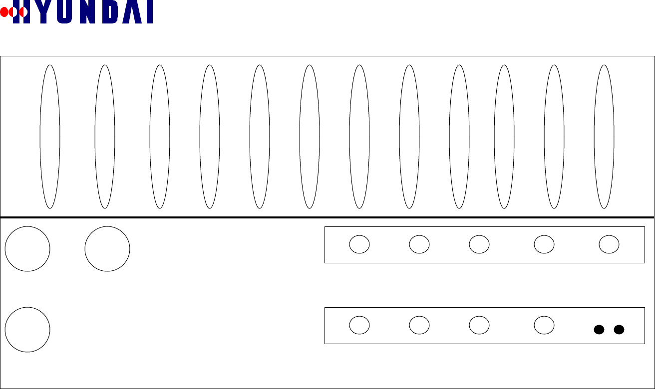
3.2 Bottom View
Figure 3.2-1
RX
GPSTX 10 MHz ESEC TRK OUT BATT AC PWR
TRK IN
TX MONO DBG GND
Rev: 1.0
Hyundai Electronics Confidential Proprietary
12
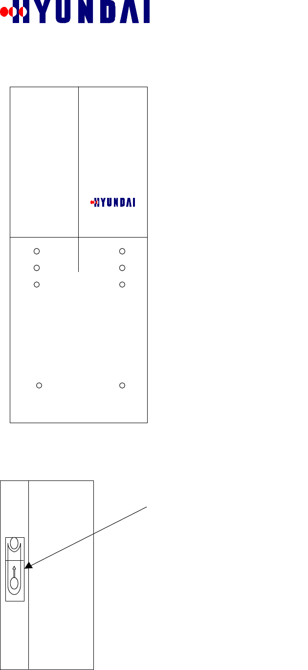
3.3 Front and Rear Views
Figure 3.3-1
Figure 3.3-2
3.4 Side Views
Figure 3.4-1 Right Side
Back side has 8 installation holes
To open the equipment lift up the
cover and you will find a key hole.
Pico-BTS
Rev: 1.0
Hyundai Electronics Confidential Proprietary
13
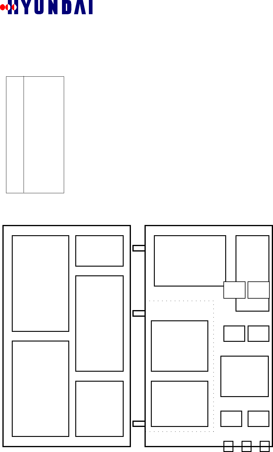
Figure 3.4-2 Left Side
3.5 Inside
Figure 3.5-1
LNAM LNAM
BBU RFU
BDC
BDC
GPRP
BAC
BCPC
XCVU HPA
PSU
DCDC
ACDC
TPLX
D/C PDET
LNA LNA

Rev: 1.0
Hyundai Electronics Confidential Proprietary
14
4. SPECIFICATIONS
The system requirements for the Pico BTS are described in this chapter.
4.1 Functional Specifications
4.1.1 Οπερατινγ Φρεθυενχψ
The Pico BTS operates at frequencies specified in the following table.
Table 4.1.1-1 DCS Operating Frequency
Items Specifications Comments
Transmit 880 - 890 MHz Base Station TransmitFrequency * B-Block Receive 835 - 845 MHz Base Station Receive
Frequency Assignment (FA) 1 Maximum 1FA/Omni
Sector 1 Maximum 1FA/1Sector(Omni)
Channel Elements 32 2 Channel cards
Number of Channel Elements/Card 16 CSM
Number of Trunks for BSC 1 T1 (or 1 E1) The other 1 T1 (or 1 E1) is used for
daisy-chain of Pico-BTSs.
RF Output (at room temperature) 8 Watts Maximum at the antenna port
RF Output (over all temperature range) ** 10 Watts Maximum at the antenna port
* For the other frequency blocks in 800MHz cellular band, it needs to replace only the duplexer/receive filter (triplexer) with another
triplexer for those blocks.
** In higher or lower temperature than room temperature, the transmit RF power may be greater than 8 Watts. So maximum power at the
antenna port should be defined as 10 Watts.
4.1.2 Ιντερφαχε Σπεχιφιχατιον
4.1.2.1 Air Interface
The Pico BTS air interface shall comply with IS-95A.
4.1.2.2 Equipment Specification
The PICO BTS equipment itself shall comply with IS-97.
4.1.2.3 Backhaul (A-bis) Interface
The interface between the Pico BTS and the BSC, i.e., A-bis interface, shall comply with Hyundai’s CDMA
DCS BSC-BTS interface.

Rev: 1.0
Hyundai Electronics Confidential Proprietary
15
4.2 Performance Specification
4.2.1 Σψστεµ ∆ελαψ
The total round-trip delay for the voice path, including the delay in the BSC, is less than 220 ms. A suggested
delay budget for the reverse link path and the forward link path is as follows:
Table 4.2.1-1 Base Station Delay Budget
Reverse Link Delay (ms) Forward Link Delay (ms)
Mobile Station 51 Mobile Station 18
Air Link 20 Air Link 20
Digital Unit 18 Digital Unit 2
Backhaul/Switching 6 CIN 8
TSB 1 TSB 1
Vocoder 3 Vocoder 49
Total 99 Total 98
4.2.2 Χαπαχιτψ
The Pico BTS is capable of physically supporting up to 32 channel elements, including all of the overhead
channels.
4.3 Electrical Performance
4.3.1 Τρανσµιττερ ΡΦ Ποωερ
The Pico BTS shall have much less RF output power than the BTS for macro-cell. The maximum CDMA
power does not exceed 10 watts at the antenna port on the enclosure over all temperature range.
4.3.2 Ελεχτριχ Ποωερ
4.3.2.1 Primary Power
The primary power source (or mains) for the Pico BTS is the commercial power which can be acquired very
easily. The nominal voltage may be 120VAC, 60Hz, single phase. The power subsystem in the Pico BTS is
capable of converting this commercial AC power into DC power with nominal voltage of +48V. The +48 DC
is then converted into lower voltages such as +5V, +12V, -12V, +3.3V and +7.5V to be used in each
subsystem.
The AC input ranges and the maximum power source requirement are as follows:
Table 4.3.2-1 Primary Power AC Input Voltage Range Requirement
Nominal Voltage Voltage Range Frequency Range Phases
120VAC 108 to 132 VAC 54 to 66 Hz single
220VAC 198 to 242 VAC 54 to 66Hz single
Table 4.3.2-2 Maximum Primary Power Output Requirement
Voltage Current Comments
DC +48 V Max 10 A For RF power 8 watts
4.3.2.2 Battery Backup Power (Optional)
The Pico BTS shall have battery backup to cope with AC power failure. The battery shall be monitored during
normal operation, and charged if necessary. The Optional backup battery is provided with an external
compartment. Table 4.3.2-3 Battery Power Requirement
Configuration DC Current/Power Comments
Nominal RF Power 5 watt 5 Amps/240 VA up to 4 Hours backup

Rev: 1.0
Hyundai Electronics Confidential Proprietary
16
Optional RF Power 10 Amps/480 VA up to 4 Hours backup
4.4 Physical Specifications
Table 4.4-1 Physical Specifications
Configuration Specifications
Size (Maximum) depth: 12 inches
height: 32 inches
width: 22 inches
Weight (Maximum) 120 pounds
Mounting Location pad, pole, wall, or vault
4.5 Environmental Specifications
The Pico BTS will meet the extended environmental specifications in rugged outdoor conditions. The
following table summarizes the environmental specifications:
Table 4.5-1 Environmental Specifications
Configuration Specifications Comments
Environmental Sealing NEMA 4X
Lightning Protection ANSI 6241 Class B
Acoustic Performance BELLCORE GR-487 60 dBA @ 5 feet
Seismic Performance BELLCORE GR-63
Random Vibration BELLCORE GR-63
Sinusoidal Vibration BELLCORE GR-63
Shock BELLCORE GR-63
EMI FCC 15.J. –6dB
BELLCORE TR-NWT-1089 FCC part 15 for USA
FCC ICES-003 for Canada
FCC part 22 in DCS band
Intrusion Resistance BELLCORE GR-487
Shotgun Resistance BELLCORE GR-487
Climatic Environment
Internal Heat Load 300 watts max.
Ambient Air Temp
( outdoor ) +500C max.
-300C min.
Solar Load 70W/sq. ft
Ambient Humidity
Continuous Operation:
Shipping and Storage:
BELLCORE TA-NWT-000487 R-
127
BELLCORE TA-NWT-000063 R98
5% - 95 % (Bellcore)
Coating
10% ~ 95%
Altitude and Rest BELLCORE GR-487 Meters max.
4.6 Reliability Specifications
4.6.1 ΜΤΒΦ

Rev: 1.0
Hyundai Electronics Confidential Proprietary
17
System down-time shall be no more than 10 minutes per year on the average, assuming a 2hour repair
(replacing) time for any failure.
4.6.2 Βαττερψ Βαχκυπ τιµε
The battery shall provide DC power until the cause of AC power is cleared. The nominal value of this time
period for backup battery operation shall be no greater than 4 hours.
4.6.3 Θυαλιτψ Ματεριαλσ
The aluminum used for the Pico BTS enclosure may be machined from aluminum 6082 in accordance with
standard QQ-A-2501/II TEMP T6.
4.6.4 Γρουνδινγ Ρεθυιρεµεντσ
The specification for grounding and electric safety shall comply with the requirement described in TR-NWT-
001089.
4.6.5 Αλαρµ Ρεθυιρεµεντσ
The Pico BTS shall require alarms for the new hardware equipment, status display information, and control
capability to monitor the system performance as follows:
! AC power failure
! DC power failure
! Malfunction of major control processors
! High internal temperature
! Low internal temperature
! Battery failure
5. Start Up
5.1 Installation
" Due to the property of the micro cell serving in a small area of dense population, the system can be
installed virtually anywhere as needed.
" System can be mounted on the PICO-BTS STAND or sturdy object such as outside wall, rooftop,
pole or inside the building using rear side hole.
Warning: PICO-BTS has to be installed by qualified personnel.
Manufacturer does not responsible for any injury or damage, which is caused by
inappropriate installation.
" The BTS shall be able to endure a wide range of environmental conditions such as high
temperature, high humidity, strong sunlight, heavy rain, and severe cold weather conditions.
6. Basic Operation
Before you running the system GPS signal has to be locked and aging process has to be done.
6.1 Power On
! Plug in to power supply, which is conforms to section 4.3.2.
! LED will show power is on
Table 6.1-1 LED on GPRP Board when power on
Green Yellow 1 Yellow 2 Green Red
Status On On Blinking Blinking Off
6.2 GPS Locking
! Connect GPS antenna to GPS port on bottom of the machine.
! Install GPS antenna where GPS signal can reach from satellite.

Rev: 1.0
Hyundai Electronics Confidential Proprietary
18
! If GPS Antenna is properly connected you will see the following signal from LED.
Table 6.2-1 LED on GPRP Board before GPS locking
Green Yellow 1 Yellow 2 Green Red
Status On On Off Off Off
! When sufficient satellite signal is received by GPS Antenna will lock.
! It takes about 15minutes. This time varies depend on the location of the GPS Antenna and satellite.
! When GPS locked you will see the following LED on the GPRP Board
Table 6.2-2 LED on GPRP Board after GPS locking
Green Yellow 1 Yellow 2 Green Red
Status On On Off On Off
6.3 Aging
! Aging takes about 1 hour after GPS locking.
! When Aging is finished you will see the following LED.
Table 6.3-1 LED on GPRP Board
Green Yellow 1 Yellow 2 Green Red
Status On Off Off On Off
If the Red LED is turn on during the operation there is possible timing problem.
When you have problem with timing you have to go over the GPS Locking and Aging procedures.
Once Aging is finished PICO-BTS is managed by BMENU, which is explained following section.
6.4 Downloading
Operator can download the data using BSAM or BSM.
BSAM method
7. BMENU
BMENU is an integrated menu of commands related to Call Processing and Call Resource Management in
Hyundai BTS. BMENU is used by manufacturing personnel to test hardware and performance. Also BMENU
is used by software personnel to test software. Service providers may initially use BMENU for performance
testing. This following section describes how to use the BMENU for Hyundai Pico BTS.
7.1 BMENU Setup
BMENU is accessed through a terminal attached to the RS232 port of BCP card in BTS (Hyundai Pico BTS
will be referred as BTS henceforth in this document). The RS232 port of BCP is connected to the Debug Port
outside BTS. Hence a terminal can be attached to the Debug Port of BTS.
The following are two ways to attach a terminal.
• Connect the Debug Port of BTS to a serial port of IBM PC compatible via RS232 cable. Use applications
like HyperTerminal for the terminal.

Rev: 1.0
Hyundai Electronics Confidential Proprietary
19
• Connect the Debug Port of BTS to a dump terminal via RS232 cable.
7.1.1 Τερµιναλ Χονφιγυρατιον
If HyperTerminal is used as the terminal of BCP, it needs to use the configuration shown in Table 7.1.1-1 in
addition to any other configuration required.
Table 7.1.1-1 HyperTerminal Configuration for BCP Terminal
PARAMETER VALUE
Bits per second 9600
Data bits 8
Stop bits 1
Parity None
Flow control None
Terminal emulation VT100
Character set ASCII
ASCII sending Send line ends with line feeds
Ταβλε 7.1.1−1
The RS232 cable used must be either crossed cable or NULL modem needs to be inserted.
7.1.2 Νοτατιοναλ Χονϖεντιονσ
This manual uses the notational conventions shown in Table 7.1.2-1 Notational Conventions (unless otherwise
noted).
NAME USAGE
Courier New Font Represents the messages displayed by BMENU or
other software on the terminal.
Courier New Font Bold Represents the user input that should be entered
exactly as shown.
Courier New Font Bold and Italic Represents the user input that may be replaced by
another valid value.
Ταβλε 7.1.2−1 Νοτατιοναλ Χονϖεντιονσ
7.2 BMENU Invocation
BMENU is invoked by inputting the command “bmenu” in BCP console prompt on the terminal. BMENU
will display the following main menu upon invocation.
NewBCP >bmenu
##################### BMENU ###################
0.Quit(BMENU exit)
1.Test Call
2.Display Message
3.Call State Flow
4.RF Characteristic Test
5.Change Local Parameters
6.Resource Status
7.Utility For CDMA System
Select MENU No ---->
The remaining sections of this manual describe usage of the menu items shown above.

Rev: 1.0
Hyundai Electronics Confidential Proprietary
20
The following are some general tips on using BMENU.
The user selects an item in a menu by inputting the number preceding the item.
All menus provide an item with number “0” for navigating to the next higher level menu.
The item “0” in the main menu is used to exit BMENU.
Many menus provide a special item with letter “T” for navigating to the main menu of BMENU. This item
can be selected by inputting letter “T”
Other BCP console commands can not be executed while within BMENU.
7.3 TEST CALL
TEST CALL menu is invoked by selecting option “1.Test Call” in the main menu. It is shown below.
Select MENU No ---->
1
=========================== TEST CALL ===========================
0.Goto TOP MENU
1.Configuration
2.Triggering (Start/Stop)
3.Result Report (Completed & Processing)
4.MARKOV([MS]->BTS->BSC) Mode(default-OFF) : ON
Select MENU No ---->
TEST CALL menu is used to trigger Test Call from the terminal. The varieties of Test Call are Markov Call,
Loop Back Call and Auto Markov Call. Test Call is used to check the path between BTS and the personal
station without the involvement of higher level entities like BSC, MSC, and BSM. Test Call is also used to
measure FER.
7.3.1 ΤΕΣΤ ΧΑΛΛ ΧΟΝΦΙΓΥΡΑΤΙΟΝ µενυ
TEST CALL CONFIGURATION menu is invoked by selecting option “1.Configuration” in TEST CALL
menu. It is shown below.
Select MENU No ---->
1
==================== TEST CALL CONFIGURATION ====================
T.Goto TOP MENU
0.Goto TEST CALL MENU
1.Input IMSI
2.Input Slot Mode
3.Input Slot Cycle Index
4.Input SERVICE OPTION
5.Display CONFIGURATION
Select MENU No ---->
TEST CALL CONFIGURATION menu is used to configure Test Call.
7.3.1.1 Menu Item: Input IMSI
Menu item “1.Input IMSI” of TEST CALL CONFIGURATION menu is used to input the IMSI_S of the
personal station in decimal. The length of IMSI_S is ten digits. The following example illustrates the usage of
this menu item.
Select MENU No ---->
1
IMSI_S (e.g. enter 2095473005 for 209-547-3005)>
2095473005
7.3.1.2 Menu Item: Input Slot Mode

Rev: 1.0
Hyundai Electronics Confidential Proprietary
21
Menu item “2.Input Slot Mode” of TEST CALL CONFIGURATION menu is used to input the Slot Mode.
Valid values of Slot Mode are 0 and 1. If incorrect value is inputted for Slot Mode, the default value of 1 will
be used for Slot Mode. The following example illustrates the usage of this menu item.
Select MENU No ---->
2
Slot Mode (0 or 1 (Default value is 1)) >
1
7.3.1.3 Menu Item: Input Slot Cycle Index
Menu item “3.Input Slot Cycle Index” of TEST CALL CONFIGURATION menu is used to input the Slot
Cycle Index in hexadecimal. Valid values of Slot Cycle Index are in the range 0 to FF. If incorrect value is
inputted for Slot Cycle Index, the default value of 0 will be used for Slot Cycle Index. The following example
illustrates the usage of this menu item.
Select MENU No ---->
3
SLOT CYCLE INDEX in Hex(Default Value is 0) >
0
7.3.1.4 Menu Item: Input SERVICE OPT ION
Menu item “4.Input SERVICE OPTION” of TEST CALL CONFIGURATION menu is used to input the
Service Option. The following examples illustrate the usage of this menu item.
Example 1: This example illustrates the selection of Service Option for a Markov Call. First the type of Test
Call is selected as Markov. Then Rate Set (8K or 13K) is selected. Finally Data Rate (1/8 or ¼ or ½ or Full or
Variable) is selected.
Select MENU No ---->
4
<<< SERVICE OPTION >>>
1 : MARKOV
2 : LOOP BACK
3 : AUTO MARKOV CALL
Select SERVICE OPTION No ---->
1
Service Option 8K(0) 13K(1) >
0
<<< Rate of MARKOV >>>
1 : 1/8 RATE
2 : 1/4 RATE
3 : 1/2 RATE
4 : FULL RATE
5 : Variable RATE
Select RATE No ----> 1
Example 2: This example illustrates the selection of Service Option for a Loop Back Call. First the type of
Test Call is selected as Loop Back. Then Rate Set (8K or 13K) is selected.
Select MENU No ---->
4
<<< SERVICE OPTION >>>
1 : MARKOV
2 : LOOP BACK
3 : AUTO MARKOV CALL

Rev: 1.0
Hyundai Electronics Confidential Proprietary
22
Select SERVICE OPTION No ---->
2
Service Option 8K(0) 13K(1) >
0
Example 3: This example illustrates the selection of Service Option for an Auto Markov Call. First the type
of Test Call is selected as Auto Markov. Then Rate Set (8K or 13K) is selected. Then Data Rate (1/8 or ¼ or
½ or Full or Variable) is selected. Finally the number of calls to be made and duration between calls are
inputted
Select MENU No ---->
4
<<< SERVICE OPTION >>>
1 : MARKOV
2 : LOOP BACK
3 : AUTO MARKOV CALL
Select SERVICE OPTION No ---->
3
Service Option 8K(0) 13K(1) >
0
<<< Rate of MARKOV >>>
1 : 1/8 RATE
2 : 1/4 RATE
3 : 1/2 RATE
4 : FULL RATE
5 : Variable RATE
Select RATE No ---->
2
<<< Input Call count & Wait time >>>
EQUIP & NORMAL TCE Number (14)
Input Call count (0 ... 14) >>
10
Input Wait time in sec (Minimum 5sec) (5 ... 65535) >>
5
7.3.1.5 Menu Item: Display CONFIGURATION
Menu item “5.Display CONFIGURATION” of TEST CALL CONFIGURATION menu is used to view the
current configuration of Test Call. The following examples illustrate the usage of this menu item.
Example 1: In this example, the configuration of a Markov Call is displayed.
Select MENU No ---->
5
<<< DISPLAY TEST CONFIGURATION >>>
MIN : 209-547-3005
SCM : 6a
Slot Cycle Index : 0
service_option : MARKOV (0x8002)
MARKOV RATE : 1/8 RATE
AUTO CALL FLAG OFF
Example 2: In this example, the configuration of a Loop Back Call is displayed.

Rev: 1.0
Hyundai Electronics Confidential Proprietary
23
Select MENU No ---->
5
<<< DISPLAY TEST CONFIGURATION >>>
MIN : 209-547-3005
SCM : 6a
Slot Cycle Index : 0
service_option : LOOP BACK(0x2)
Example 3: In this example, the configuration of an Auto Markov Call is displayed.
Select MENU No ---->
5
<<< DISPLAY TEST CONFIGURATION >>>
MIN : 209-547-3005
SCM : 6a
Slot Cycle Index : 0
service_option : AUTO MARKOV CALL (0x8002)
MARKOV RATE : 1/4 RATE
AUTO CALL FLAG ON & Selected Data Review
----------------------------------------
CDMA_IDX : 0
CALL COUNT : 10
WAIT TIME : 5 SEC
7.3.2 Μενυ Ιτεµ: Τριγγερινγ (Σταρτ/Στοπ)
Menu item “2.Triggering (Start/Stop)” of TEST CALL menu is used to start or stop Test Call from the
terminal. The current configuration of Test Call is used for triggering Test Call. The following examples
illustrate the usage of this menu item.
Example 1: In this example, Markov Call or Loop Back Call is started. The option Start (value 1) is selected.
Select MENU No ---->
2
<<< Triggering (Start(1) / Stop(0)) >>>
1
[BCOX BMENU] TEST CALL Started !
Example 2: In this example, an Auto Markov Call is started. By selecting FREE option for TCE, the selection
of TCE for each call is left to the BTS.
Select MENU No ---->
2
<<< Triggering (Start(1) / Stop(0)) >>>
1
You can fix a TCE : (FIX(1) / FREE(any key)) >>
[BCOX BMENU] AUTO CALL Started : 10 Call(s) !
Example 3: In this example, an Auto Markov Call is started. The TCE used is determined by the user by
choosing FIX option for TCE. TCE is identified by inputting values of shelf, slot of BDC, and subnode of
TCE in BDC.
Select MENU No ---->
2
<<< Triggering (Start(1) / Stop(0)) >>>
1
You can fix a TCE : (FIX(1) / FREE(any key)) >>

Rev: 1.0
Hyundai Electronics Confidential Proprietary
24
1
SHELF >>
0
SLOT >>
4
SUBNODE >>
5
Shelf : 0, Slot : 4, Subnode : 5 Please verify ( OK(1) / NOT_OK(0) ) >>
1
[BCOX BMENU] AUTO CALL Started : 2 Call(s) !
Example 4: In this example, Markov Call or Loop Back Call is stopped. The option Stop (value 0) is
selected. The identifier of the call to stopped can be found using item “3.Call State Flow” in the main menu.
Select MENU No ---->
2
<<< Triggering (Start(1) / Stop(0)) >>>
0
Input TEST CALL Id >>>
99
Example 5: In this example, Auto Markov Call is stopped.
Select MENU No ---->
2
<<< Triggering (Start(1) / Stop(0)) >>>
0
[BCOX BMENU] TEST CALL stopped
[BCOX BMENU] Remaining Call count is (10)
7.3.3 Μενυ Ιτεµ: Ρεσυλτ Ρεπορτ (Χοµπλετεδ & Προχεσσινγ)
Menu item “3.Result Report (Completed & Processing)” of TEST CALL menu is used to display results from
Test Call.
Note: This menu item is not fully implemented now.
7.3.4 Μενυ Ιτεµ: ΜΑΡΚΟς([ΜΣ]−>ΒΤΣ−>ΒΣΧ) Μοδε(δεφαυλτ−ΟΦΦ)
Menu item “4.MARKOV([MS]->BTS->BSC) Mode(default-OFF)” of TEST CALL menu is used to set or
reset Markov Mode. Markov Mode decides the involvement of higher level entities like BSC in a Markov
Call triggered from a personal station. Markov Mode should be set to OFF when triggering a Markov Call
from a personal station. Markov Mode does not affect Test Call. The following example illustrates the usage
of this menu item.
=========================== TEST CALL ===========================
0.Goto TOP MENU
1.Configuration
2.Triggering (Start/Stop)
3.Result Report (Completed & Processing)
4.MARKOV([MS]->BTS->BSC) Mode(default-OFF) : ON
Select MENU No ---->
4
=========================== TEST CALL ===========================
0.Goto TOP MENU
1.Configuration
2.Triggering (Start/Stop)

Rev: 1.0
Hyundai Electronics Confidential Proprietary
25
3.Result Report (Completed & Processing)
4.MARKOV([MS]->BTS->BSC) Mode(default-OFF) : OFF
Select MENU No ---->
4
=========================== TEST CALL ===========================
0.Goto TOP MENU
1.Configuration
2.Triggering (Start/Stop)
3.Result Report (Completed & Processing)
4.MARKOV([MS]->BTS->BSC) Mode(default-OFF) : ON
Select MENU No ---->
7.4 DISPLAY MESSAGE
DISPLAY MESSAGE menu is invoked by selecting option “2.Display Message” in the main menu. It is
shown below.
Select MENU No ---->
2
======================== DISPLAY MESSAGE ========================
0.Goto TOP MENU
1.Related with Device Configuration
(TFC,ACC,CCC,PSYN,PSA,ACH,PCH,TCH,RFC)
2.Related with Call Control(CCP,ACH,PCH,TCH)
Select MENU No ---->
DISPLAY MESSAGE menu is used to turn on and off the displaying of Call Processing messages and
Configuration messages.
7.4.1 ∆ΕςΙΧΕ ΧΟΝΦΙΓΥΡΑΤΙΟΝ ΜΕΣΣΑΓΕ ∆ΙΣΠΛΑΨ µενυ
DEVICE CONFIGURATION MESSAGE DISPLAY menu is invoked by selecting option “1.Related with
Device Configuration (TFC, ACC, CCC, PSYN, PSA, ACH, PCH, TCH, RFC)” in DISPLAY MESSAGE
menu. It is shown below.
Select MENU No ---->
1
============== DEVICE CONFIGURATION MESSAGE DISPLAY =============
T.Goto TOP MENU
0.Goto DISPLAY MESSAGE
1.TX Message
2.RX Message
Select MENU No ---->
DEVICE CONFIGURATION MESSAGE DISPLAY menu is used to turn on and off the displaying of
Configuration messages.
7.4.1.1 DEVICE CONFIGURATION TX MESSAGE DISPLAY MASK menu
DEVICE CONFIGURATION TX MESSAGE DISPLAY MASK menu is invoked by selecting option “1.TX
Message” in DEVICE CONFIGURATION MESSAGE DISPLAY menu. It is shown below.
Select MENU No ---->
1

Rev: 1.0
Hyundai Electronics Confidential Proprietary
26
========= DEVICE CONFIGURATION TX MESSAGE DISPLAY MASK ==========
T.Goto TOP MENU
0.Goto DEVICE CONFIGURATION MESSAGE DISPLAY
1.All OFF Message
2.All ON Message
3.Tx BSM Message : OFF
4.Tx CCP Message : OFF
5.Tx Other BCP Message : OFF
6.Tx CCC Message : OFF
7.Tx TCE Message : OFF
8.Tx PCE Message : OFF
9.Tx PSA Message : OFF
10.Tx ACE Message : OFF
11.Tx PSYN Message : OFF
12.Tx TFC Message : OFF
13.Tx TCC Message : OFF
Select MENU No ---->
DEVICE CONFIGURATION TX MESSAGE DISPLAY MASK menu is used to turn on or off the displaying
of Configuration messages transmitted from BCP to other devices.
7.4.1.2 DEVICE CONFIGURATION RX MESSAGE DISPLAY MASK menu
DEVICE CONFIGURATION RX MESSAGE DISPLAY MASK menu is invoked by selecting option “2.RX
Message” in DEVICE CONFIGURATION MESSAGE DISPLAY menu. It is shown below.
Select MENU No ---->
2
========= DEVICE CONFIGURATION RX MESSAGE DISPLAY MASK ==========
T.Goto TOP MENU
0.Goto DEVICE CONFIGURATION MESSAGE DISPLAY
1.All OFF Message
2.All ON Message
3.Rx BSM Message : OFF
4.Rx CCP Message : OFF
5.Rx Other BCP Message : OFF
6.Rx CCC Message : OFF
7.Rx TCE Message : OFF
8.Rx PCE Message : OFF
9.Rx PSA Message : OFF
10.Rx ACE Message : OFF
11.Rx PSYN Message : OFF
12.Rx TFC Message : OFF
13.Rx TCC Message : OFF
Select MENU No ---->
DEVICE CONFIGURATION RX MESSAGE DISPLAY MASK menu is used to turn on or off the displaying
of Configuration messages received in BCP from other devices.
7.4.2 ΧΑΛΛ ΧΟΝΤΡΟΛ ΜΕΣΣΑΓΕ ∆ΙΣΠΛΑΨ µενυ
CALL CONTROL MESSAGE DISPLAY menu is invoked by selecting option “2.Related with Call
Control(CCP,ACH,PCH,TCH)” in DISPLAY MESSAGE menu. It is shown below.
Select MENU No ---->
2

Rev: 1.0
Hyundai Electronics Confidential Proprietary
27
================= CALL CONTROL MESSAGE DISPLAY ==================
T.Goto TOP MENU
0.Goto DISPLAY MESSAGE
1.TX CCP Message
2.RX CCP Message
3.TX TCE Message
4.RX TCE Message
5.TX PCE Message
6.RX PCE Message
7.RX ACE Message
Select MENU No ---->
CALL CONTROL MESSAGE DISPLAY menu is used to turn on and off the displaying of Call Processing
messages.
7.4.2.1 TX CCP MESSAGE DISPLAY MASK menu
TX CCP MESSAGE DISPLAY MASK menu is invoked by selecting option “1.TX CCP Message” in CALL
CONTROL MESSAGE DISPLAY menu. It is shown below.
Select MENU No ---->
1
================== TX CCP MESSAGE DISPLAY MASK ==================
T.Goto TOP MENU
0.Goto CALL CONTROL MESSAGE DISPLAY
1.All OFF Message
2.All ON Message
3.Tx Mobile Registration Message : OFF
4.Tx Handoff Channel Allocation Response Message : OFF
5.Tx Release Message : OFF
6.Tx Mobile Origination Message : OFF
7.Tx Page Response Message : OFF
8.Tx Mobile Power Control Fail Message : OFF
9.Tx Channel Assignment Completion Message : OFF
10.Tx Undefined Message : OFF
Select MENU No ---->
TX CCP MESSAGE DISPLAY MASK menu is used to turn on and off the displaying of Call Processing
messages sent to CCP from BCP.
7.4.2.2 RX CCP MESSAGE DISPLAY MASK menu
RX CCP MESSAGE DISPLAY MASK menu is invoked by selecting option “2.RX CCP Message” in CALL
CONTROL MESSAGE DISPLAY menu. It is shown below.
Select MENU No ---->
2
================== RX CCP MESSAGE DISPLAY MASK ==================
T.Goto TOP MENU
0.Goto CALL CONTROL MESSAGE DISPLAY
1.All OFF Message
2.All ON Message
3.Rx Mobile Page Message : OFF
4.Rx Mobile Order Message : OFF
5.Rx Mobile Release Message : OFF

Rev: 1.0
Hyundai Electronics Confidential Proprietary
28
6.Rx Handoff Channel Allocation Request Message : OFF
7.Rx Handoff Channel Free Message : OFF
8.Rx Mobile Origination Acknowledgement Message : OFF
9.Rx Page Response Acknowledgement Message : OFF
10.Rx Channel Assignment Request Message : OFF
Select MENU No ---->
RX CCP MESSAGE DISPLAY MASK menu is used to turn on and off the displaying of Call Processing
messages received by BCP from CCP.
7.4.2.3 TX TRAFFIC CHANNEL ELEMENT (TCE) MESSAGE DISPLAY MASK menu
TX TRAFFIC CHANNEL ELEMENT MESSAGE DISPLAY MASK menu is invoked by selecting option
“3.TX TCE Message” in CALL CONTROL MESSAGE DISPLAY menu. It is shown below.
Select MENU No ---->
3
====== TX TRAFFIC CHANNEL ELEMENT (TCE) MESSAGE DISPLAY MASK ======
T.Goto TOP MENU
0.Goto CALL CONTROL MESSAGE DISPLAY
1.All OFF Message
2.All ON Message
3.Tx Mobile Station Assignment Message : OFF
4.Tx Call Release Message : OFF
5.Tx Undefined Message : OFF
Select MENU No ---->
TX TRAFFIC CHANNEL ELEMENT MESSAGE DISPLAY MASK menu is used to turn on and off the
displaying of Call Processing messages sent to Traffic Channel Element from BCP.
7.4.2.4 RX TRAFFIC CHANNEL ELEMENT (TCE) MESSAGE DISPLAY MASK menu
RX TRAFFIC CHANNEL ELEMENT MESSAGE DISPLAY MASK menu is invoked by selecting option
“4.RX TCE Message” in CALL CONTROL MESSAGE DISPLAY menu. It is shown below.
Select MENU No ---->
4
===== RX TRAFFIC CHANNEL ELEMENT (TCE) MESSAGE DISPLAY MASK =====
T.Goto TOP MENU
0.Goto CALL CONTROL MESSAGE DISPLAY
1.All OFF Message
2.All ON Message
3.Rx Call Status Message : OFF
4.Rx Softer Handoff Request Message : OFF
5.Rx Call Release Message : OFF
6.Rx Handoff Complete Message : OFF
7.Rx Forward Link Power Control Report Message : OFF
8.Rx Error Message : OFF
9.Rx Softer Handoff Swap Message : OFF
Select MENU No ---->
RX TRAFFIC CHANNEL ELEMENT MESSAGE DISPLAY MASK menu is used to turn on and off the
displaying of Call Processing messages received by BCP from Traffic Channel Element.
7.4.2.5 TX PAGING CHANNEL ELEMENT (PCE) MESSAGE DISPLAY MASK menu
TX PAGING CHANNEL ELEMENT MESSAGE DISPLAY MASK menu is invoked by selecting option

Rev: 1.0
Hyundai Electronics Confidential Proprietary
29
“5.TX PCE Message” in CALL CONTROL MESSAGE DISPLAY menu. It is shown below.
Select MENU No ---->
5
===== TX PAGING CHANNEL ELEMENT (PCE) MESSAGE DISPLAY MASK ======
T.Goto TOP MENU
0.Goto CALL CONTROL MESSAGE DISPLAY
1.All OFF Message
2.All ON Message
3.Tx General Page Message : OFF
4.Tx Order Message : OFF
5.Tx Channel Assignment Message : OFF
6.Tx Data Burst Message : OFF
7.Tx Authentication Challenge Message : OFF
8.Tx SSD Update Message : OFF
9.Tx Feature Notification Message : OFF
10.Tx Status Request Message : OFF
11.Tx Service Redirection Message : OFF
12.Tx Global Service Redirection Message : OFF
13.Tx TMSI Assignment Message : OFF
14.Tx Undefined Message : OFF
Select MENU No ---->
TX PAGING CHANNEL ELEMENT MESSAGE DISPLAY MASK menu is used to turn on and off the
displaying of Call Processing messages sent to Paging Channel Element from BCP.
7.4.2.6 RX PAGING CHANNEL ELEMENT (PCE) MESSAGE DISPLAY MASK menu
RX PAGING CHANNEL ELEMENT MESSAGE DISPLAY MASK menu is invoked by selecting option
“6.RX PCE Message” in CALL CONTROL MESSAGE DISPLAY menu. It is shown below.
Select MENU No ---->
6
===== RX PAGING CHANNEL ELEMENT (PCE) MESSAGE DISPLAY MASK ======
T.Goto TOP MENU
0.Goto CALL CONTROL MESSAGE DISPLAY
1.All OFF Message
2.All ON Message
3.Rx Tx OTA Message : OFF
Select MENU No ---->
RX PAGING CHANNEL ELEMENT MESSAGE DISPLAY MASK menu is used to turn on and off the
displaying of Call Processing messages received by BCP from Paging Channel Element.
7.4.2.7 RX ACCESS CHANNEL ELEMENT (ACE) MESSAGE DISPLAY MASK menu
RX ACCESS CHANNEL ELEMENT MESSAGE DISPLAY MASK menu is invoked by selecting option
“7.RX ACE Message” in CALL CONTROL MESSAGE DISPLAY menu. It is shown below.
Select MENU No ---->
7
===== RX ACCESS CHANNEL ELEMENT (ACE) MESSAGE DISPLAY MASK ======
T.Goto TOP MENU

Rev: 1.0
Hyundai Electronics Confidential Proprietary
30
0.Goto CALL CONTROL MESSAGE DISPLAY
1.All OFF Message
2.All ON Message
3.Rx Registration Message : OFF
4.Rx Order Message : OFF
5.Rx Origination Message : OFF
6.Rx Page Response Message : OFF
7.Rx Data Burst Message : OFF
8.Rx Authentication Challenge Response Message : OFF
9.Rx Status Response Message : OFF
10.Rx TMSI Assignment Completion Message : OFF
Select MENU No ---->
RX ACCESS CHANNEL ELEMENT MESSAGE DISPLAY MASK menu is used to turn on and off the
displaying of Call Processing messages received by BCP from Access Channel Element.
7.5 CALL STATE FLOW
CALL STATE FLOW menu is invoked by selecting option “3.Call State Flow” in the main menu. It is shown
below.
Select MENU No ---->
3
======================== CALL STATE FLOW ========================
0.Goto TOP MENU
1.Call Flow Display
2.Processing Call State Display
Select MENU No ---->
CALL STATE FLOW menu is used to turn on and off the displaying of Call Processing steps. This menu is
also used to display information about currently active calls.
7.5.1 ΧΑΛΛ ΦΛΟΩ ∆ΙΣΠΛΑΨ µενυ
CALL FLOW DISPLAY menu is invoked by selecting option “1.Call Flow Display” in CALL STATE FLOW
menu. It is shown below.
Select MENU No ---->
1
======================= CALL FLOW DISPLAY =======================
T.Goto TOP MENU
0.Goto CALL STATE FLOW
1.Mobile Trace
2.Initial Call Flow : OFF
3.Registration Call Flow : OFF
4.Hand Off Call Flow : OFF
5.Channel Allocation Data : OFF
6.Debug Data : OFF
7.Channel Dup Flow : OFF
Select MENU No ---->
CALL FLOW DISPLAY menu is used to turn on and off the displaying of Call Processing steps. The menu
item numbered 1 is used to turn on and off the displaying of Call Processing steps involved in Call
Origination and Call Termination. Menu Items 2 through 7 can be used to turn on and off displaying of
additional Call Processing steps.
7.5.1.1 CALL ID TRACE menu

Rev: 1.0
Hyundai Electronics Confidential Proprietary
31
CALL ID TRACE menu is invoked by selecting option “1.Mobile Trace” in CALL FLOW DISPLAY menu.
It is shown below.
Select MENU No ---->
1
========================= CALL ID TRACE =========================
0.Goto CALL FLOW DISPLAY
1.ALL CALL FLOW DISPLAY(OFF/ON) : OFF
2.MOBILE(imsi_s1) TRACE : DISABLE
Select MENU No ---->
CALL ID TRACE menu is used to turn on and off the displaying of Call Processing steps for a particular
personal station or all personal stations.
7.5.1.1.1 Menu Item: ALL CALL FLOW DISPLAY(OFF/ON)
Menu item “1.ALL CALL FLOW DISPLAY(OFF/ON)” of CALL ID TRACE menu is used to turn on and
off the displaying of Call Processing steps for all personal stations. It is also used to turn off the displaying of
Call Processing steps for a particular personal station. The following example illustrates the usage of this
menu item to turn on and off the displaying of Call Processing steps for all personal stations.
Select MENU No ---->
1
========================= CALL ID TRACE =========================
0.Goto CALL FLOW DISPLAY
1.ALL CALL FLOW DISPLAY(OFF/ON) : ON
2.MOBILE(imsi_s1) TRACE : DISABLE
Select MENU No ---->
1
========================= CALL ID TRACE =========================
0.Goto CALL FLOW DISPLAY
1.ALL CALL FLOW DISPLAY(OFF/ON) : OFF
2.MOBILE(imsi_s1) TRACE : DISABLE
Select MENU No ---->
7.5.1.1.2 Menu Item: MOBILE(imsi_s1) TRACE
Menu item “2.MOBILE(imsi_s1) TRACE” of CALL ID TRACE menu is used to turn on displaying of Call
Processing steps for a particular personal station. Menu item “1.ALL CALL FLOW DISPLAY(OFF/ON)” of
CALL ID TRACE menu is used to turn off the displaying of Call Processing steps for a particular personal
station. The following example illustrates the usage of these menu items to turn on and off the displaying of
Call Processing steps for a particular personal station.
Select MENU No ---->
2
Input IMSI
IMSI_S (e.g. enter 2095473005 for 209-547-3005)>
2095473005
========================= CALL ID TRACE =========================
0.Goto CALL FLOW DISPLAY
1.ALL CALL FLOW DISPLAY(OFF/ON) : DISABLE
2.MOBILE(imsi_s1) TRACE : 547-3005

Rev: 1.0
Hyundai Electronics Confidential Proprietary
32
Select MENU No ---->
1
========================= CALL ID TRACE =========================
0.Goto CALL FLOW DISPLAY
1.ALL CALL FLOW DISPLAY(OFF/ON) : OFF
2.MOBILE(imsi_s1) TRACE : DISABLE
Select MENU No ---->
7.5.2 Μενυ Ιτεµ: Προχεσσινγ Χαλλ Στατε ∆ισπλαψ
Menu item “2.Processing Call State Display” of CALL STATE FLOW menu is used to display information
about currently active calls. This menu item is usually used to find the Call Id of an active call. The following
example illustrates the usage of this menu item.
Select MENU No ---->
2
Do you want call information?[y/n]
y
=======================================================================
======================================================================
======================== CALL DATA BASE =======================
---------------------------------------------------------------------------
CALL_TYPE ,CALL_ID, ESN , TEL_NO ,LINK,OFFSET,TCE_ADDR,SECTOR(walsh),
ORIG_CALL , 0103, a00a0004, 547-3004, 0 , 11 ,01000047, 0(21) ,
MARKOV_CALL, 0104, a00a0005, 547-3005, 0 , 12 ,01000048, 0(22) ,
CALL/FA(775) : ch_idx(0),total(2),alpha(2),beta(0),gamma(0),softer(0)
Total calls in BTS : 2
7.6 RF CHARACTERISTICS
RF CHARACTERISTICS menu is invoked by selecting option “4.RF Characteristic Test” in the main menu.
It is shown below.
Select MENU No ---->
4
======================= RF CHARACTERISTICS ======================
0.Goto Main Menu
1.RF TEST CALL Start
2.RF TEST CALL Release
Select MENU No ---->
RF CHARACTERISTICS menu is used to test RF characteristics by making RF Test Calls without a personal
station. Tx power for RF Test Calls can be assigned as if the call is in real service. RF Test Calls can be used
to measure Tx output spurious characteristics and total output power.
7.6.1 Μενυ Ιτεµ: ΡΦ ΤΕΣΤ ΧΑΛΛ Σταρτ
Menu item “1.RF TEST CALL Start” of RF CHARACTERISTICS menu is used to make RF Test Calls.
Information about RF Test Calls made can viewed using CALL STATE FLOW menu. The following
examples illustrate the usage of this menu item.

Rev: 1.0
Hyundai Electronics Confidential Proprietary
33
Example 1: In this example, 13 RF Test Calls are made. The parameters inputted are CDMA channel index (in
prompt CDMA), sector, Traffic Channel Gain and Service Option. The number of calls to be made is then
inputted. BMENU then makes specified number of calls.
Select MENU No ---->
1
CDMA (0, 1, 2, 3)>
0
SECTOR (Alpha:0, Beta:1, Gamma:2)>
0
TC GAIN (Normal 65: MAX:125)>
65
Service Option( 8K(0x8002):0, 13K(0x801F):1 )>
0
CDMA(0),SECTOR(0),TC GAIN(65) usable_calls(13) S_Opt(8002)
Change Parameters (0:exit, 1:continue, 2:change)?
1
Select Mode (STEP_BY_STEP(1), CALLS(any key))?
[BCOX BMENU] Selected CALLS MODE
Number of Calls (Maximum : 13)>
13
Example 2: In this example, 2 RF Test Calls are made. STEP_BY_STEP mode is selected so that BMENU
will prompt for the next call after making a call.
Select MENU No ---->
1
CDMA (0, 1, 2, 3)>
0
SECTOR (Alpha:0, Beta:1, Gamma:2)>
0
TC GAIN (Normal 65: MAX:125)>
65
Service Option( 8K(0x8002):0, 13K(0x801F):1 )>
0
CDMA(0),SECTOR(0),TC GAIN(65) usable_calls(12) S_Opt(8002)
Change Parameters (0:exit, 1:continue, 2:change)?
1
Select Mode (STEP_BY_STEP(1), CALLS(any key))?
1
[BCOX BMENU] Selected STEP_BY_STEP MODE
[BCOX] lib_alloc return code for RF TEST (1)
[BCOX BMENU] SETUP TEST CALL call_id(99) cdma_idx(0) sector(0),
BMENU] Do you want keep pre-call(y/n)?
y
BMENU] Continue Call setup(y/n)?
y
[BCOX] lib_alloc return code for RF TEST (1)
[BCOX BMENU] SETUP TEST CALL call_id(100) cdma_idx(0) sector(0),

Rev: 1.0
Hyundai Electronics Confidential Proprietary
34
BMENU] Do you want keep pre-call(y/n)?
y
BMENU] Continue Call setup(y/n)?
n
[BCOX BMENU] Stop Test call
7.6.2 Μενυ Ιτεµ: ΡΦ ΤΕΣΤ ΧΑΛΛ Ρελεασε
Menu item “2.RF TEST CALL Release” of RF CHARACTERISTICS menu is used to release RF Test Calls.
The following examples illustrate the usage of this menu item.
Example 1: In this example, all RF Test Calls are released.
Select MENU No ---->
2
Release All Test Call (y/n)>
y
Release RF Test Call (ALL)
Change Call id (0:exit, 1:continue, 2:change)?
1
Example 2: In this example, a RF Test Call with call id 73 is released. The identifier of the call to stopped can
be found using item “3.Call State Flow” in the main menu.
Select MENU No ---->
2
Release All Test Call (y/n)>
n
Release RF Test Call. Input Call Id>
73
Release call id(73)
Change Call id (0:exit, 1:continue, 2:change)?
1
7.7 LOCAL PARAMETER
LOCAL PARAMETER menu is invoked by selecting option “5.Change Local Parameters” in the main menu.
It is shown below.
Select MENU No ---->
5
======================== LOCAL PARAMETER ========================
0.Goto TOP MENU
1.Display Current Local Parameter
2.Change Local Parameter
Select MENU No ---->
LOCAL PARAMETER menu is used to display and change value of local parameters.
7.7.1 ∆ΙΣΠΛΑΨ ΛΟΧΑΛ ΠΑΡΑΜΕΤΕΡ µενυ
DISPLAY LOCAL PARAMETER menu is invoked by selecting option “1.Display Current Local Parameter”
in LOCAL PARAMETER menu. It is shown below.

Rev: 1.0
Hyundai Electronics Confidential Proprietary
35
Select MENU No ---->
1
==================== DISPLAY LOCAL PARAMETER ====================
T.Goto TOP MENU
0.Goto LOCAL PARAMETER
1.Display Pilot, Sync and Paging Channel Gains
2.Display RFC Tx Gain
Select MENU No ---->
DISPLAY LOCAL PARAMETER menu is used to display value of local parameters.
7.7.1.1 Menu Item: Display Pilot, Sync and Paging Channel Gains
Menu item “1.Display Pilot, Sync and Paging Channel Gains” of DISPLAY LOCAL PARAMETER menu is
used to display the Pilot Channel Gain, Sync Channel Gain, Paging Channel Gain, and Traffic Channel Gain
The following example illustrates the usage of this menu item.
Select MENU No ---->
1
cdma(0), sector(0)] PILOT(108,108), SYNC(34,34), PG_0(65,65),
PG_1(65,65), PG_2(65,65)
tc_gain(50)
7.7.1.2 Menu Item: Display RFC Tx Gain
Menu item “2.Display RFC Tx Gain” of DISPLAY LOCAL PARAMETER menu is used to display the RFC
TX gain. The following example illustrates the usage of this menu item.
Select MENU No ---->
2
[cdma(0), sector(0)] Tx Attenuation(0,0)
7.7.2 ΧΗΑΝΓΕ ΛΟΧΑΛ ΠΑΡΑΜΕΤΕΡ µενυ
CHANGE LOCAL PARAMETER menu is invoked by selecting option “2.Change Local Parameter” in
LOCAL PARAMETER menu. It is shown below.
Select MENU No ---->
2
===================== CHANGE LOCAL PARAMETER ====================
T.Goto TOP MENU
0.Goto LOCAL PARAMETER
1.Change Pilot Channel Gain
2.Change Sync Channel Gain
3.Change Paging Channel Gain
4.Change Traffic Channel Gain
5.Change RFC Gain
Select MENU No ---->
CHANGE LOCAL PARAMETER menu is used to change value of local parameters.
7.7.2.1 Menu Item: Change Pilot Channel Gain
Menu item “1.Change Pilot Channel Gain” of CHANGE LOCAL PARAMETER menu is used to change the
Pilot Channel Gain. The following example illustrates the usage of this menu item.
Select MENU No ---->

Rev: 1.0
Hyundai Electronics Confidential Proprietary
36
1
Pilot Channel Gain(Current 108:MAX:125)>
108
CDMA(0), SECTOR(0), PILOT GAIN(108)
Change Parameters (0:exit, 1:continue, 2:change)?
1
7.7.2.2 Menu Item: Change Sync Channel Gain
Menu item “2.Change Sync Channel Gain” of CHANGE LOCAL PARAMETER menu is used to change the
Sync Channel Gain. The following example illustrates the usage of this menu item.
Select MENU No ---->
2
Sync Channel Gain(Current 34:MAX:125)>
34
CDMA(0), SECTOR(0), SYNC GAIN(34)
Change Parameters (0:exit, 1:continue, 2:change)?
1
7.7.2.3 Menu Item: Change Paging Channel Gain
Menu item “3.Change Paging Channel Gain” of CHANGE LOCAL PARAMETER menu is used to change
the Paging Channel Gain. The following example illustrates the usage of this menu item.
Select MENU No ---->
3
Paging Channel ID(MAX:3)>
0
Paging Channel Gain(Current 65:MAX:125)>
65
CDMA(0),SECTOR(0),PC_ID(0),PAGE GAIN(65)
Change Parameters (0:exit, 1:continue, 2:change)?
1
7.7.2.4 Menu Item: Change Traffic Channel Gain
Menu item “4.Change Traffic Channel Gain” of CHANGE LOCAL PARAMETER menu is used to change
the Traffic Channel Gain. The following example illustrates the usage of this menu item.
Select MENU No ---->
4
TCE CH GAIN(Current 50:MAX:125)>
50
CDMA(0),SECTOR(0),TCE GAIN(50)
Change Parameters (0:exit, 1:continue, 2:change)?
1
7.7.2.5 Menu Item: Change RFC Gain
Menu item “5.Change RFC Gain” of CHANGE LOCAL PARAMETER menu is used to change the RFC
Gain. . The following example illustrates the usage of this menu item.

Rev: 1.0
Hyundai Electronics Confidential Proprietary
37
Select MENU No ---->
5
RFC GAIN(Current 0(MAX:0 - MIN:127))>
0
CDMA(0),SECTOR(0),RFC ATTEN(0)
Change Parameters (0:exit, 1:continue, 2:change)?
1
7.8 RESOURCE STATUS
RESOURCE STATUS menu is invoked by selecting option “6.Resource Status” in the main menu. It is shown
below.
Select MENU No ---->
6
======================== RESOURCE STATUS ========================
0.Goto TOP MENU
1.Display Carrier(BLINK) data
2.Display Channel Card data
3.Display Walsh Code
4.Display Power bank
5.Display Using TCE
Select MENU No ---->
RESOURCE STATUS menu is used to display the status of Call Resources.
7.8.1 Μενυ Ιτεµ: ∆ισπλαψ Χαρριερ(ΒΛΙΝΚ) δατα
Menu item “1.Display Carrier(BLINK) data” of RESOURCE STATUS menu is used to display status of
BLINK. The following example illustrates the usage of this menu item.
Select MENU No ---->
1
CARRIER(id)>>block, cur_stat, user_per_offset, use_cnt
(frameoffset), use,use_cnt
----------------------------------------------------------------
CARRIER(0)>> M_UBLK, NORMAL,6, 1
(00),IDLE,0,(01),IDLE,0,(02),IDLE,0,(03),IDLE,1
(04),IDLE,0,(05),IDLE,0,(06),IDLE,0,(07),IDLE,0
(08),IDLE,0,(09),IDLE,0,(10),IDLE,0,(11),IDLE,0
(12),IDLE,0,(13),IDLE,0,(14),IDLE,0,(15),IDLE,0
7.8.2 ∆ΙΣΠΛΑΨ ΧΗΑΝΝΕΛ ΧΑΡ∆ ∆ΑΤΑ µενυ
DISPLAY CHANNEL CARD DATA menu is invoked by selecting option “2.Display Channel Card data” in
RESOURCE STATUS menu. It is shown below.
Select MENU No ---->
2

Rev: 1.0
Hyundai Electronics Confidential Proprietary
38
=================== DISPLAY CHANNEL CARD DATA ===================
T.Goto TOP MENU
0.Goto RESOURCE STATUS
1.Display Channel Card
2.Display Pilot and Sync Channel
3.Display Paging Channel
4.Display Access Channel
5.Display Traffic Channel
6.Display Error Rate of Traffic Channel
Select MENU No ---->
DISPLAY CHANNEL CARD DATA menu is used to display the status of channel cards.
7.8.2.1 Menu Item: Display Channel Card
Menu item “1.Display Channel Card” of DISPLAY CHANNEL CARD DATA menu is used to display
Channel Card data. The following example illustrates the usage of this menu item.
Select MENU No ---->
1
CDMA >> block,cdma_id,cdma_num,cdma_kind,rstr_tce,alloc_tce
M_UBLK, 0, 775, COMMON, 014, 001
-----------------------------------------------------------------------
[Du, Slot, Ch_Card_id] Block, Status, Hina_address
[00, 3, 03] M_UBLK, ABNORMAL, 01000030
[00, 4, 04] M_UBLK, NORMAL, 01000040
-----------------------------------------------------------------------
7.8.2.2 Menu Item: Display Pilot and Sync Channel
Menu item “2.Display Pilot and Sync Channel” of DISPLAY CHANNEL CARD DATA menu is used to
display the status of Pilot Channel and Sync Channel. The following example illustrates the usage of this
menu item.
Select MENU No ---->
2
CDMA >> block,cdma_id,cdma_num,cdma_kind,rstr_tce,alloc_tce
0FA >> M_UBLK, 0, 775, COMMON, 014, 001
-----------------------------------------------------------------------
[du,sl,su, id] ch_type, block, status, w_a, w_b, w_g, address
[ 0, 4, 2, 0] PSA, M_UBLK, NORMAL,(0,32), xx, xx,BUSY 01000041
Do you want other CDMA_CH's information ? (y/n) --> Yes
Other CDMA_CH is Not Equiped !!!
7.8.2.3 Menu Item: Display Paging Channel
Menu item “3.Display Paging Channel” of DISPLAY CHANNEL CARD DATA menu is used to display the
status of Paging Channel. The following example illustrates the usage of this menu item.
Select MENU No ---->

Rev: 1.0
Hyundai Electronics Confidential Proprietary
39
3
CDMA >> block,cdma_id,cdma_num,cdma_kind,rstr_tce,alloc_tce
0FA >> M_UBLK, 0, 775, COMMON, 014, 001
-----------------------------------------------------------------------
[du,sl,su, id] ch_type, block, status, w_a, w_b, w_g, address
[ 0, 4, 1, 0] PCE, M_UBLK, NORMAL, 1, xx, xx, 01000040
Do you want other CDMA_CH's information ? (y/n) --> Yes
Other CDMA_CH is Not Equiped !!!
7.8.2.4 Menu Item: Display Access Channel
Menu item “4.Display Access Channel” of DISPLAY CHANNEL CARD DATA menu is used to display the
status of Access Channel. The following example illustrates the usage of this menu item.
Select MENU No ---->
4
CDMA >> block,cdma_id,cdma_num,cdma_kind,rstr_tce,alloc_tce
0FA >> M_UBLK, 0, 775, COMMON, 014, 001
-----------------------------------------------------------------------
[sh,sl,su, id] ch_type, block, status, w_a, w_b, w_g, address
[ 0, 4, 2, 0] PSA, M_UBLK, NORMAL, xx, xx, xx, 01000041
Do you want other CDMA_CH's information ? (y/n) --> Yes
Other CDMA_CH is Not Equiped !!!
7.8.2.5 Menu Item: Display Traffic Channel
Menu item “5.Display Traffic Channel” of DISPLAY CHANNEL CARD DATA menu is used to display the
status of Traffic Channel. The following example illustrates the usage of this menu item.
Select MENU No ---->
5
If you want (EQUIP & (NORMAL & ABNORMAL), input '0'
If you want (EQUIP & NORMAL) , input '1'
If you want (EQUIP & ABNORMAL) , input '2'
Select STATUS(0,1,2) >
0
CDMA >> block,cdma_id,cdma_num,cdma_kind,rstr_tce,alloc_tce
M_UBLK, 0, 775, COMMON, 014, 001
------------------------------------------------------------------------
[du,sl,su, id] block, status, use, carr,frame, w_a, w_b, w_g, address
[ 0, 3, 1, 72] M_UBLK,ABNORMAL, IDLE, xx, xx, xx, xx, xx, 01000030
[ 0, 3, 2, 73] M_UBLK,ABNORMAL, IDLE, xx, xx, xx, xx, xx, 01000031
[ 0, 3, 3, 74] M_UBLK,ABNORMAL, IDLE, xx, xx, xx, xx, xx, 01000032
[ 0, 3, 4, 75] M_UBLK,ABNORMAL, IDLE, xx, xx, xx, xx, xx, 01000033
[ 0, 3, 5, 76] M_UBLK,ABNORMAL, IDLE, xx, xx, xx, xx, xx, 01000034
[ 0, 3, 6, 77] M_UBLK,ABNORMAL, IDLE, xx, xx, xx, xx, xx, 01000035
[ 0, 3, 7, 78] M_UBLK,ABNORMAL, IDLE, xx, xx, xx, xx, xx, 01000036
[ 0, 3, 8, 79] M_UBLK,ABNORMAL, IDLE, xx, xx, xx, xx, xx, 01000037
[ 0, 3, 9, 80] M_UBLK,ABNORMAL, IDLE, xx, xx, xx, xx, xx, 01000038
[ 0, 3,10, 81] M_UBLK,ABNORMAL, IDLE, xx, xx, xx, xx, xx, 01000039
[ 0, 3,11, 82] M_UBLK,ABNORMAL, IDLE, xx, xx, xx, xx, xx, 0100003a
[ 0, 3,12, 83] M_UBLK,ABNORMAL, IDLE, xx, xx, xx, xx, xx, 0100003b
[ 0, 3,13, 84] M_UBLK,ABNORMAL, IDLE, xx, xx, xx, xx, xx, 0100003c

Rev: 1.0
Hyundai Electronics Confidential Proprietary
40
[ 0, 3,14, 85] M_UBLK,ABNORMAL, IDLE, xx, xx, xx, xx, xx, 0100003d
[ 0, 3,15, 86] M_UBLK,ABNORMAL, IDLE, xx, xx, xx, xx, xx, 0100003e
[ 0, 3,16, 87] M_UBLK,ABNORMAL, IDLE, xx, xx, xx, xx, xx, 0100003f
Do you want other TCE information ? (y/n) -->
y
Other TCE Information Display
[ 0, 4, 3, 98] M_UBLK, NORMAL, IDLE, xx, xx, xx, xx, xx, 01000042
[ 0, 4, 4, 99] M_UBLK, NORMAL, IDLE, xx, xx, xx, xx, xx, 01000043
[ 0, 4, 5,100] M_UBLK, NORMAL, IDLE, xx, xx, xx, xx, xx, 01000044
[ 0, 4, 6,101] M_UBLK, NORMAL, IDLE, xx, xx, xx, xx, xx, 01000045
[ 0, 4, 7,102] M_UBLK, NORMAL, IDLE, xx, xx, xx, xx, xx, 01000046
[ 0, 4, 8,103] M_UBLK, NORMAL, IDLE, xx, xx, xx, xx, xx, 01000047
[ 0, 4, 9,104] M_UBLK, NORMAL, IDLE, xx, xx, xx, xx, xx, 01000048
[ 0, 4,10,105] M_UBLK, NORMAL, IDLE, xx, xx, xx, xx, xx, 01000049
[ 0, 4,11,106] M_UBLK, NORMAL, IDLE, xx, xx, xx, xx, xx, 0100004a
[ 0, 4,12,107] M_UBLK, NORMAL, IDLE, xx, xx, xx, xx, xx, 0100004b
[ 0, 4,13,108] M_UBLK, NORMAL, IDLE, xx, xx, xx, xx, xx, 0100004c
[ 0, 4,14,109] M_UBLK, NORMAL, IDLE, xx, xx, xx, xx, xx, 0100004d
[ 0, 4,15,110] M_UBLK, NORMAL, IDLE, xx, xx, xx, xx, xx, 0100004e
[ 0, 4,16,111] M_UBLK, NORMAL, BUSY, 0, 3, 15, xx, xx, 0100004f
7.8.2.6 Menu Item: Display Error Rate of Traffic Channel
Menu item “6.Display Error Rate of Traffic Channel” of DISPLAY CHANNEL CARD DATA menu is used
to display the error rate of Traffic Channel. The following example illustrates the usage of this menu item.
Select MENU No ---->
6
If you want (EQUIP & (NORMAL & ABNORMAL), input '0'
If you want (EQUIP & NORMAL) , input '1'
If you want (EQUIP & ABNORMAL) , input '2'
Select STATUS(0,1,2) >
0
[du,sl,su, id] status, alloc_cnt, abnor_cnt, suc_rate,ms_ack,bs_ack,reset
[ 0, 3, 1, 72]ABNORMAL, 0, 0, 100 per, 0, 0, 0
[ 0, 3, 2, 73]ABNORMAL, 0, 0, 100 per, 0, 0, 0
[ 0, 3, 3, 74]ABNORMAL, 0, 0, 100 per, 0, 0, 0
[ 0, 3, 4, 75]ABNORMAL, 0, 0, 100 per, 0, 0, 0
[ 0, 3, 5, 76]ABNORMAL, 0, 0, 100 per, 0, 0, 0
[ 0, 3, 6, 77]ABNORMAL, 0, 0, 100 per, 0, 0, 0
[ 0, 3, 7, 78]ABNORMAL, 0, 0, 100 per, 0, 0, 0
[ 0, 3, 8, 79]ABNORMAL, 0, 0, 100 per, 0, 0, 0
[ 0, 3, 9, 80]ABNORMAL, 0, 0, 100 per, 0, 0, 0
[ 0, 3, 10, 81]ABNORMAL, 0, 0, 100 per, 0, 0, 0
[ 0, 3, 11, 82]ABNORMAL, 0, 0, 100 per, 0, 0, 0
[ 0, 3, 12, 83]ABNORMAL, 0, 0, 100 per, 0, 0, 0
[ 0, 3, 13, 84]ABNORMAL, 0, 0, 100 per, 0, 0, 0
[ 0, 3, 14, 85]ABNORMAL, 0, 0, 100 per, 0, 0, 0
[ 0, 3, 15, 86]ABNORMAL, 0, 0, 100 per, 0, 0, 0
[ 0, 3, 16, 87]ABNORMAL, 0, 0, 100 per, 0, 0, 0
Do you want other TCE information ? (y/n) -->
y
Other TCE Information Display

Rev: 1.0
Hyundai Electronics Confidential Proprietary
41
[ 0, 4, 3, 98] NORMAL, 2, 0, 100 per, 0, 0, 0
[ 0, 4, 4, 99] NORMAL, 2, 0, 100 per, 0, 0, 0
[ 0, 4, 5,100] NORMAL, 2, 0, 100 per, 0, 0, 0
[ 0, 4, 6,101] NORMAL, 2, 0, 100 per, 0, 0, 0
[ 0, 4, 7,102] NORMAL, 2, 0, 100 per, 0, 0, 0
[ 0, 4, 8,103] NORMAL, 1, 0, 100 per, 0, 0, 0
[ 0, 4, 9,104] NORMAL, 1, 0, 100 per, 0, 0, 0
[ 0, 4, 10,105] NORMAL, 1, 0, 100 per, 0, 0, 0
[ 0, 4, 11,106] NORMAL, 1, 0, 100 per, 0, 0, 0
[ 0, 4, 12,107] NORMAL, 1, 0, 100 per, 0, 0, 0
[ 0, 4, 13,108] NORMAL, 1, 0, 100 per, 0, 0, 0
[ 0, 4, 14,109] NORMAL, 1, 0, 100 per, 0, 0, 0
[ 0, 4, 15,110] NORMAL, 1, 0, 100 per, 0, 0, 0
[ 0, 4, 16,111] NORMAL, 1, 0, 100 per, 0, 0, 0
END DISPLAY !!!
Clear Error_Rate DB ? (y/n) -->
n
7.8.3 Μενυ Ιτεµ: ∆ισπλαψ Ωαλση Χοδε
Menu item “3.Display Walsh Code” of RESOURCE STATUS menu is used to display the Walsh Code used.
The following example illustrates the usage of this menu item.
Select MENU No ---->
3
Walsh(cdma,sector,walsh)>>use_flag, ch_type,alloc_pwr
Walsh( 0, 0, 0)>> BUSY, PILOT, 108
Walsh( 0, 0, 1)>> BUSY, PCE, 065
Walsh( 0, 0, 15)>> BUSY, TCE, 050
Walsh( 0, 0, 32)>> BUSY, SYNC, 034
Do you want other CDMA_CH's information ? (y/n) --> Yes
Other CDMA_CH is Not Equiped !!!
7.8.4 Μενυ Ιτεµ: ∆ισπλαψ Ποωερ βανκ
Menu item “4.Display Power bank” of RESOURCE STATUS menu is used to display the Power Bank data.
The following example illustrates the usage of this menu item.
Select MENU No ---->
4
######## 0 FA ########
SECTOR >> block, bank, tc_t,pilot,sync,pc_t,shr_ths,unshr_th,shr_cnt,ush_cnt
-------------------------------------------------------------------------------
Alpha >> M_UBLK,007871,000050, 108, 034,0065, 00000, 00000, 16777216,
7065048
Do you want other CDMA_CH's information ? (y/n) --> YES
Other CDMA_CH is Not Equiped !!!
7.8.5 Μενυ Ιτεµ: ∆ισπλαψ Υσινγ ΤΧΕ
Menu item “5.Display Using TCE” of RESOURCE STATUS menu is used to display the status of TCEs in
use. The following example illustrates the usage of this menu item.

Rev: 1.0
Hyundai Electronics Confidential Proprietary
42
Select MENU No ---->
5
CDMA >> block,cdma_id,cdma_num,cdma_kind,rstr_tce,alloc_tce
M_UBLK, 0, 775, COMMON, 014, 001
------------------------------------------------------------------------
[du,sl,su, id] block, status, use, carr,frame, w_a, w_b, w_g, address
[ 0, 4,16,111] M_UBLK, NORMAL, BUSY, 0, 3, 15, xx, xx, 0100004f
Call(1) in CDMA(0): ALPHA(1),BETA(0),GAMMA(0),SFTR_ADD(0)
Do you want other CDMA_CH's information ? (y/n) -->
y
Other CDMA_CH is Not Equiped !!!
7.9 CDMA Utility
CDMA Utility menu is invoked by selecting option “7.Utility For CDMA System” in the main menu. It is
shown below.
Select MENU No ---->
7
========================= CDMA Utility =========================
0.Goto Main Menu
1.Phone Number --> MIN
2.MIN --> Phone Number
3.Hash Randomize
Select MENU No ---->
CDMA Utility menu provides some useful utilities.
7.9.1 Μενυ Ιτεµ: Πηονε Νυµβερ −−> ΜΙΝ
Menu item “1.Phone Number --> MIN” of CDMA Utility menu is used to convert IMSI_S in decimal to
IMSI_S1 and IMSI_S2. The following example illustrates the usage of this menu item.
Select MENU No ---->
1
Input MIN
IMSI_S (e.g. enter 2095473005 for 209-547-3005)>
2095473005
IMSI_S1 = 6d0fe2h
IMSI_S2 = 0c6h
7.9.2 Μενυ Ιτεµ: ΜΙΝ −−> Πηονε Νυµβερ
Menu item “2.MIN --> Phone Number” of CDMA Utility menu is used to convert IMSI_S1 and IMSI_S2 in
hexadecimal to IMSI_S in decimal. The following example illustrates the usage of this menu item.
Select MENU No ---->
2
Input MIN1 in Hex (e.g. 2eebe6)
MIN1>
6d0fe2
Input MIN2 in Hex (e.g. 384)
MIN2>
0c6
MIN1 = 6d0fe2h
MIN2 = 0c6h

Rev: 1.0
Hyundai Electronics Confidential Proprietary
43
Phone Number = 209-547-3005
7.9.3 Ηαση Ρανδοµιζε µενυ
Hash Randomize menu is invoked by selecting option “3.Hash Randomize” in CDMA Utility menu. It is
shown below.
Select MENU No ---->
3
======================== Hash Randomize ========================
T.Goto TOP MENU
0.Goto Main Menu
1.Random CDMA Channel Index
2.Random Paging Channel Number
3.Random Paging Slot
4.Random Access Channel PN
Select MENU No ---->
Hash Randomize menu is used to execute some hash functions.
7.9.3.1 Menu Item: Random CDMA Channel Index
Menu item “1.Random CDMA Channel Index” of CDMA Utility menu is used to view CDMA Channel
Index and FA selected. The following example illustrates the usage of this menu item.
Select MENU No ---->
1
<<< Input Parameters For Random CDMA >>>
Input IMSI
IMSI_S (e.g. enter 2095473005 for 209-547-3005)>
2095473005
Inputted Parameters >> CDMA(1), imsi_s1(6d0fe2h), imsi_s2(0c6h)
Selected CDMA >> CDMA_IDX(0) : FA(775)
7.9.3.2 Menu Item: Random Paging Channel Number
Menu item “2.Random Paging Channel Number” of CDMA Utility menu is used to view Paging Channel
number selected. The following example illustrates the usage of this menu item.
Select MENU No ---->
2
<<< Input Parameters For Random PAGE >>>
Input Equipped Paging Channel Number(1,2,...,6,7) =
1
Input IMSI
IMSI_S (e.g. enter 2095473005 for 209-547-3005)>
2095473005
Inputted Parameters >> PAGE(1), imsi_s1(6d0fe2h), imsi_s2(0c6h)
Selected PAGE >> Paging Channel Number(1)
7.9.3.3 Menu Item: Random Paging Slot
Menu item “3.Random Paging Slot” of CDMA Utility menu is used to view the hash number and Paging Slot

Rev: 1.0
Hyundai Electronics Confidential Proprietary
44
Number selected. The following example illustrates the usage of this menu item.
Select MENU No ---->
3
<<< Input Parameters For Random Paging Slot >>>
Input IMSI
IMSI_S (e.g. enter 2095473005 for 209-547-3005)>
2095473005
Input SLOT_CYCLE_INDEX(0 ... 7) >
0
Inputted Parameters >> imsi_s1(6d0fe2h), imsi_s2(0c6h), Slot Cycle
Index(0)
Selected Paging Slot >> Hash Number(5efh), Paging Slot Number(15)
7.9.3.4 Menu Item: Random Access Channel PN
Menu item “4.Random Access Channel PN” of CDMA Utility menu is used to view the Access Channel PN
selected. The following example illustrates the usage of this menu item.
Select MENU No ---->
4
<<< Input Parameters For Random Access Channel PN >>>
Input PROBE_PN_RAN (0 ... 9) =
5
Input IMSI
IMSI_S (e.g. enter 2095473005 for 209-547-3005)>
2095473005
Inputted Parameters >> PROBE_PN_RAN(5), imsi_s1(6d0fe2h), imsi_s2(0c6h)
Selected Access Channel PN >> (11)

Rev: 1.0
Hyundai Electronics Confidential Proprietary
45
8. Maintenance Advice
8.1 Operation/Configuration Management
The Pico BTS is able to manage the data related to the operation and configuration of its subsystems. Some
examples are as follows:
" Initial loading
" Radio resource management
" hardware configuration data management
" CDMA parameter management
8.2 Performance Management
The Pico BTS is able to collect and analyze data related to the performance of the system, and send them to
the appropriate higher level entity for management. Some examples are as follows:
" Call processing related parameters statistics collection
" Radio performance related parameters statistics collection
" Periodic reporting
8.3 Maintenance Management
The Pico BTS is able to perform the detection, isolation, and restoration of elements operating abnormally.
Some examples follow.
" Fault detection and management
" Alarm generation and processing
" Periodic test of maintenance/diagnosis
" Status management