Hyundai Electronics Co PIC800 User Manual System Description
Hyundai Electronics Industries Co Ltd System Description
Contents
- 1. System Description
- 2. OperationsMANUAL
System Description

Rev: 1.0
Hyundai Electronics Confidential and Proprietary
1
PICO-BTS
PICO-BTS PICO-BTS
PICO-BTS EQUIPMENT
EQUIPMENTEQUIPMENT
EQUIPMENT
DESCRIPTION
DESCRIPTIONDESCRIPTION
DESCRIPTION
(800MHZ CELLULAR BANDS)

Rev: 1.0
Hyundai Electronics Confidential and Proprietary
2
Table of Contents
1. INTRODUCTION
1.1 Scope 8
1.2 Applicable Documents and Standards 8
2. SPECIFICATIONS
2.1 Functional Specifications 8
2.1.1 Operating Frequency 8
2.1.2 Interface Specification 8
2.1.3 Operational and Maintenance 9
2.1.4 Configuration Features 9
2.2 Performance Specification 9
2.2.1 System Delay 9
2.2.2 Capacity 10
2.3 Electrical Performance 10
2.3.1 Transmitter RF Power 10
2.3.2 Electric Power 10
2.4 Physical Specifications 11
2.5 Environmental Specifications 11
2.6 Reliability Specifications 11
2.6.1 MTBF 11
2.6.2 Battery Backup time 11
2.6.3 Quality Materials 11
2.6.4 Grounding Requirements 11
2.6.5 Alarm Requirements 11
3. SYSTEM DESCRIPTION
3.1 System Functionality 12
3.1.1 Configuration 12
3.1.2 Initialization 12
3.1.3 Call Control 12
3.1.4 Maintenance and Administration 13
3.1.5 Network Operation 13
3.2 System Architecture 14
3.2.1 Functional Architecture 14
3.3 System Interface 16
3.3.1 External Interface 16
3.4 System Availability, Maintenance, and Environmental Enhancement 16

Rev: 1.0
Hyundai Electronics Confidential and Proprietary
3
3.4.1 System Availability 16
3.4.2 System Maintenance 16
3.4.3 Environmental Enhancement 16
3.5 Pico BTS Block Condiguration 17
3.5.1 Baseband Unit (BBU) 17
3.5.2 RF Unit (RFU) 18
4. HARDWARE STRUCTURE AND FUNCTIONS
4.1 RF Subsystem 19
4.1.1 Functionality 19
4.1.2 Architecture 20
4.2 Pico Baseband Digital Card (BDC) 24
4.2.1 Functionality 24
4.3 Pico BTS Control Processor Card (BCPC) 24
4.4 BTS Baseband Analog Card(BAC) 25
4.5 GPS Receiver Processor (GPRP) 26
4.6 Power Supplies (ACDC, BBDC) 26
4.7 Mechanical / Thermal Design 27
4.7.1 Background 27
4.7.2 Mechanical Characteristics / Requirements 27
4.7.3 Thermal and Environmental Characteristics / Requirements 27
4.7.4 Design Strategies 27
5. SOFTWARE DESCRIPTIONS
5.1 Pico BTS Control Processor Card (BCPC) 28
5.1.1 Functional Overview 28
5.1.2 BCPC Boot Software (pBCPCb) 29
5.1.3 BCPC Software Architecture Overview 29
5.1.4 Interfaces 30
5.1.5 Software Blocks 31
5.1.6 Interrupt Service Routines 40
5.2 Baseband Digital Card (BDC) 40
5.2.1 Functional Overview 40
5.2.2 BDC Boot Software(pBDCb) 42
5.2.3 pBDCX Software Architectural Overview 43
5.2.4 Interfaces 43
5.2.5 Software Blocks 44
5.3 Inter Processor Communication (IPC) 45
5.4 Inter Module Communication (IMC) 46
5.4.1 Functional Overview 46

Rev: 1.0
Hyundai Electronics Confidential and Proprietary
4
5.4.2 Firmware 47
5.4.3 Software Architecture Overview 47
5.5 Backhaul Interface Handler (BIH) 48
5.5.1 Functional Overview 48
List of Figures
FIGURE.3.2-1 FUNCTIONAL ARCHITECTURE ......................................................................................14
FIGURE 3.5.1-1 BASE BAND UNIT ...........................................................................................................17
FIGURE 3.5.2-1 RF UNIT.............................................................................................................................18
FIGURE 4.1-1 HARDWARE FUNCTIONAL BLOCK DIAGRAM...........................................................19
FIGURE 4.1.2-1 RF SUBSYSTEM ARCHITECTURE................................................................................20
FIGURE 4.1.2-2 .............................................................................................................................................21
FIGURE 4.1.2-3 TX FRONT END ARCHITECTURE ................................................................................21
FIGURE 4.1.2-4 UP-CONVERTER BLOCK DIAGRAM ...........................................................................22
FIGURE 4.1.2-5 A DOWN-CONVERTER BLOCK DIAGRAM...............................................................23
FIGURE 4.2-1 MAJOR INTERFACES OF BDC .........................................................................................24
FIGURE 4.3-1 ................................................................................................................................................25
FIGURE 4.4-1 OVERALL FUNCTIONAL BLOCK DIAGRAM OF BAC...............................................26
FIGURE 4.6-1 FUNCTIONAL BLOCK DIAGRAM OF THE POWER SUPPLIES ..................................27
FIGURE 5.1.3-1 BCPCSOFTWARE ARCHITECTURE.............................................................................30
FIGURE 5.1.5-1 BCM EXTERNAL INTERFACE DIAGRAM..................................................................31
FIGURE 5.1.5-2 PBRMX EXTERNAL INTERFACE DIAGRAM.............................................................33
FIGURE 5.1.5-3 PBSHX EXTERNAL INTERFACE DIAGRAM..............................................................34
FIGURE 5.1.5-4 PBTS DIAGNOSTICS EXTERNAL INTERFACE DIAGRAM......................................36
FIGURE 5.4.3-1 IMC SW ARCHITECTURE ..............................................................................................47
FIGURE 5.4.3-2 BCPC IMC SOFTWARE ARCHITECTURE....................................................................47
List of Tables
TABLE 2.1.1-1 CELLULAR OPERATING FREQUENCY ERROR! BOOKMARK NOT DEFINED.
TABLE 2.2.1-1 BASE STATION DELAY BUDGET 10
TABLE 2.3.2-1 PRIMARY POWER AC INPUT VOLTAGE RANGE REQUIREMENT 10
TABLE 2.3.2-2 MAXIMUM PRIMARY POWER OUTPUT REQUIREMENT 10
TABLE 2.3.2-3 BATTERY POWER REQUIREMENT 10
TABLE 2.4-1 PHYSICAL SPECIFICATIONS 11
TABLE 2.5-1 ENVIRONMENTAL SPECIFICATIONS 11
TABLE 3.2.1-1 16
TABLE 4.1.2-1 22

Rev: 1.0
Hyundai Electronics Confidential and Proprietary
5
Glossary
AC Alternate Current
ACC Analog Common Circuit, replaced by BAC
ACCA Analog Common Card Assembly
ACE Access Channel Element
ACRP Adjacent Channel Power Rejection
ADC Analog To Digital
AGC Automatic Gain Controller
ANT Antenna
BAC Baseband Analog Circuit, replacing ACC
BBU Base Band Unit
BCP BTS Control Processor
BCM BTS Configuration Management
BCOX BTS Call Control Execution
BDAX BCP Data Access Execution
BDC Baseband Digital Card
BDIAX BTS Diagnostic Execution
BDTU BTS Diagnostic & Test Unit
BFMX BTS Fault Management Execution
BIH Backhaul Interface Handler - Software
BIU Backhaul Interface Unit
BMEA BCP Measurement
BLINK BTS Link
BPF Band Pass Filter
BPLX BCP Processor Loader Execution
BRAX BTS Resource Allocation Execution
BRMX BTS Resource Management Execution
BS Base Station
BSC Base Station Controller
BSHX BTS Status Handler Execution
BSM Base Station Manager
BTS Base Transceiver System
BW Band Width
CAI Common Air Interface
CCC Channel Card Common, replaced by CEC
CCP Call Control Processor
CDIAX CCP Diagnostic Execution
CDMA Code Division Multiple Access
CDMX Configuration Data Management Execution
CE Channel Element
CEC Channel Element Controller, replacing CCC
CFMX CCP Fault Management Execution
CMEA CCP Measurement
CPLX CCP Processor Loader Execution
CRAX CCP Resource Allocation Execution
CSHX CCP Status Handler Execution

Rev: 1.0
Hyundai Electronics Confidential and Proprietary
6
CSM Cell Site Modem
DAC Digital to Analog Converter
DC Direct Current
DD Detailed Design
DDS Direct Digital Synthesis
DM Diagnostic Monitor
DU Digital Unit
EMI Electrical Magnetic Interface
FA Frequency Allocation
FIFO First-In-First-Out
FPGA Field-Programmable-Gate_Array
GPIO General Purpose Input / Output
GPS Global Position System
HDLC High Level Data Link Control
HLD High Level Design
IIn_Phase
IF Intermediate Frequency
IMC Inter Module Communication
IMCB Inter Module Communication Bus
IMCH Inter Module Communication Handler - Software
IPC Inter Processor Communication
LCIN Local CCP Interconnection Network
LED Light Emitting Diode
LNA Low Noise Amplifier
LO1 Local Oscillator 1
LO2 Local Oscillator 2
LPA Linear Power Amplifier
LPF Low Pass Filter
MFP Multi-Function Peripheral
MLNK MSC Link
MMI Man Machine Interface
MRB Monitor/Report Block
MS Mobile Station
MSC Mobile Switch Center
MSPS Mega Sample Per Second
MTBF Mean Time Between Failure
MUX Multiplexor
MVIP Multiple Vendor Integrated Protocol
OC Overload Controller
OPAID Operation AID
PA Power Amplifier
PCI Peripheral Communication Interface
PCE Paging Channel Element
PCS Personal Communication System
PN Pseudo-Noise Sequence
PLD Program Load Data
PLL Phase Lock Loop
PLX Process Loading Execution
PP2S/ Pulse Per Two Second
PSCE Pilot_Sync Channel Element

Rev: 1.0
Hyundai Electronics Confidential and Proprietary
7
PSU Power Subsystem Unit
PSU Power Subsystem Unit
Q Quadrature
RF Radio Frequency
RFC Radio Frequency Controller
RFFE RF Front End
RFU Radio Frequency Unit
ROM Read Only Memory
RxFE Receiver Front End
RxIF Receiver IF
SCC Serial Communication Controller
SIP Selector Interface Processor
SNR Signal To Noise Ratio
SRAM Static Read Only Memory
SVE Selector Vocoder Element
SVP Selector Vocoder Processor
TBD To Be Determined
T_BLK Test Block
TCE Traffic Channel Element
TDM Time Division Multiplexing
TFC Time & Frequency Controller
TxIF Transmitter IF
TxFE Transmitter Front End
TFU Time and Frequency Unit
TSB Transcoder Selector Bank
UART Universal Asynchronous Receiver Transmitter
XCVC Radio Frequency Transceiver

Rev: 1.0
Hyundai Electronics Confidential and Proprietary
8
1. INTRODUCTION
1.1 Scope
This document describes the Pico Base Transceiver Station for CDMA cellular systems. The
Pico-BTS provides the interface between the CDMA cellular mobile stations and the Base Station
Controller (BSC) to form a Picocell. Picocells are used to enhance the coverage by covering the
“dead spot” caused by shadowing in traditional “macrocell” based cellular networks. Also
Picocells can be used to increase the capacity of the network as small underlay cells, providing
more channels for traffic in dense urban areas with high volume of low speed traffic, such as
malls, airports, train and subway stations, hotels, and office building areas.
1.2 Applicable Documents and Standards
1. TIA/EIA/IS-95-A, Mobile Station-Base Station Compatibility Standard for Dual-ModeWideband
Spread Spectrum Cellular System, May 1995.
2. TIA/EIA/IS-97-A, Minimum Performance Standards for Base Stations Supporting Dual-Mode
Wideband Spread Spectrum Cellular Mobile Stations, June 1997.
3. EIA/TIA IS-634, MSC-BS Interface for Public Wireless Communications Systems
4. NEMA 4X
5. ANSI 6241 Class B
6. FCC Part 15 for USA
7. FCC ICES-003 for Canada
8. FCC Part 22 in cellular band
9. FCC Part 68
10. FCC Part 2
11. TA-NWT-000487 R-127
12. TA-NWT-000063 R98
13. EIA/TIA IS-125, Recommended Minimum Performance Standard for Digital Cellular
Wideband Spread Spectrum Speech Service Option 1.
14. EIA/TIA IS-126A, Mobile Station Loopback Service Option Standard
2. SPECIFICATIONS
The system requirements for the Pico-BTS are described in this chapter.
2.1 Functional Specifications
2.1.1 Operating Frequency
The Pico-BTS operates at frequencies specified in the following table.
Table 2.1.1-1 Operating Frequency
Unit Frequency Range (MHz)
Transmitter 869 - 894
Receiver 824 - 849
The Pico-BTS can cover all sub-bands only replacing the duplexer / BFP.
2.1.2 Interface Specification
2.1.2.1 Air Interface
The Pico BTS shall comply with EIA/TIA/IS-95-A.
2.1.2.2 Backhaul(A-bis) Interface

Rev: 1.0
Hyundai Electronics Confidential and Proprietary
9
The interface between the Pico-BTS and the BSC, i.e., A-bis interface, shall comply with
Hyundai’s CDMA Cellular BSC-BTS interface.
2.1.3 Operational and Maintenance
2.1.3.1 Operation/Configuration Management
The Pico-BTS is able to manage the data related to the operation and configuration of its
subsystems. Some examples are as follows:
! Initial loading
! Radio resource management
! hardware configuration data management
! CDMA parameter management
2.1.3.2 Performance Management
The Pico-BTS is able to collect and analyze data related to the performance of the system, and
send them to the appropriate higher level entity for management. Some examples are as follows:
! Call processing related parameters statistics collection
! Radio performance related parameters statistics collection
! Periodic reporting
2.1.3.3 Maintenance Management
The Pico-BTS is able to perform the detection, isolation, and restoration of elements operating
abnormally. Some examples follow.
! Fault detection and management
! Alarm generation and processing
! Periodic test of maintenance/diagnosis
! Status management
2.1.4 Configuration Features
! The system supports one FA, omni-cell, or unidirectional sectored cell. It uses
directional antenna to serve a sector.
! A 3-sector cell site can be configured with 3 Pico-BTSs as primary equipment in each
direction. When any sectors need more capacity, additional Pico BTSs can be stacked
on each sector separately. Multiple Pico-BTS can be daisy-chained using one T1/E1
trunk to BSC.
! The Pico BTS can serve as a stand-alone cell site, or it can be overlaid by another
CDMA macro-cell.
! Due to the small capacity of the Pico-BTS, the backhaul efficiency may be a concern
from the economic point of view. In order to avoid this, multiple Pico BTSs shall be
able to share a single backhaul transmission facility.
! Any one of the channel elements may be configured to support one of the following:
◊ A pilot channel and a sync channel
◊ An access channel
◊ A paging channel
◊ A traffic channel
2.2 Performance Specification
2.2.1 System Delay
The total round-trip delay for the voice path, including the delay in the BSC, is less than 220 ms.
A suggested delay budget for the reverse link path and the forward link path is as follows:

Rev: 1.0
Hyundai Electronics Confidential and Proprietary
10
Table 2.2.1-1 Base Station Delay Budget
Reverse Link Delay (ms) Forward Link Delay (ms)
Mobile Station 51 Mobile Station 18
Air Link 20 Air Link 20
Digital Unit 18 Digital Unit 2
Backhaul/Switching 6 CIN 8
TSB 1 TSB 1
Vocoder 3 Vocoder 49
Total 99 Total 98
2.2.2 Capacity
The Pico BTS is capable of physically supporting up to 32 channel elements, including all of the
overhead channels.
2.3 Electrical Performance
2.3.1 Transmitter RF Power
The maximum CDMA power does not exceed 10 watts at the antenna port on the enclosure over
operating temperature range.
2.3.2 Electric Power
2.3.2.1 Primary Power
The primary power source (or mains) for the Pico BTS is the commercial power which can be
acquired very easily. The nominal voltage may be 120VAC, 60Hz, single phase. The power
subsystem in the Pico BTS is capable of converting this commercial AC power into DC power
with nominal voltage of +48V. The +48 DC is then converted into lower voltages such as +5V,
+12V, -12V, +3.3V and +7.5V to be used in each subsystem.
The AC input ranges and the maximum power source requirement are as follows:
Table 2.3.2-1 Primary Power AC Input Voltage Range Requirement
Nominal Voltage Voltage Range Frequency Range Phases
120VAC 108 to 132 VAC 54 to 66 Hz single
220VAC 198 to 242 VAC 54 to 66Hz single
Table 2.3.2-2 Maximum Primary Power Output Requirement
Voltage Current Comments
DC +48 V Max 10 A For RF power 8 watts
2.3.2.2 Battery Backup Power (Optional)
The Pico BTS shall have battery backup to cope with AC power failure. The battery shall be
monitored during normal operation, and charged if necessary. The Optional backup battery is
provided with an external compartment.
` Table 2.3.2-3 Battery Power Requirement
Configuration DC Current/Power Comments
Nominal RF Power 5 watt 5 Amps/240 VA up to 4 Hours backup
Optional RF Power 10 Amps/480 VA up to 4 Hours backup

Rev: 1.0
Hyundai Electronics Confidential and Proprietary
11
2.4 Physical Specifications
Table 2.4-1 Physical Specifications
Configuration Specifications
Size Max. depth: 12 inched
height: 32 in
width: 22 in
Weight max. 110 pounds
Mounting Location pad, pole, wall, or vault
2.5 Environmental Specifications
The Pico BTS will meet the extended environmental specifications in rugged outdoor conditions.
The following table summarizes the environmental specifications:
Table 2.5-1 Environmental Specifications
Configuration Specifications Comments
Environmental Sealing NEMA 4X
Lightning Protection ANSI 6241 Class B
Climatic Environment
Internal Heat Load 300 watts max.
Ambient Air Temp
( outdoor ) +500C max.
-400C min.
Solar Load 70W/sq. ft
2.6 Reliability Specifications
2.6.1 MTBF
System down-time shall be no more than 10 minutes per year on the average, assuming a 2hour
repair (replacing) time for any failure.
2.6.2 Battery Backup time
The battery shall provide DC power until the cause of AC power is cleared. The nominal value of
this time period for backup battery operation shall be no greater than 4 hours.
2.6.3 Quality Materials
The aluminum used for the Pico-BTS enclosure may be machined from aluminum 6082 in
accordance with standard QQ-A-2501/II TEMP T6.
2.6.4 Grounding Requirements
The specification for grounding and electric safety shall comply with the requirement described
in TR-NWT-001089.
2.6.5 Alarm Requirements
The Pico BTS shall require alarms for the new hardware equipment, status display information,
and control capability to monitor the system performance as follows:
" AC power failure
" DC power failure
" Malfunction of major control processors
" High internal temperature
" Low internal temperature
" Battery failure

Rev: 1.0
Hyundai Electronics Confidential and Proprietary
12
3. SYSTEM DESCRIPTION
3.1 System Functionality
The details of the hardware and software functionality are described in section 4 and section 5,
respectively. In this section, only brief outlines and essential details of several critical factors are
discussed.
3.1.1 Configuration
3.1.1.1 BSM Configurability
As an element of the existing network, Pico-BTS should be similar to existing BTSs from BSM’s
point of view. Therefore, the basic nomenclature of its subsystem dividing and configuration
should be similar to that of existing network in which it is supposed to work. By doing this, it is
possible to use the existing messages and BSM screen entities with which the BSM operator
might be familiar, to configure and manage this new element.
3.1.1.2 Initialization - Configuration
No redundancy will be provided in the Pico-BTS. Therefore once the system is configured
through the initialization process, hardware configuration is not changed unless the whole system
is removed. The only change in hardware may be the number of channel card. The Pico-BTS can
support 32 channel elements. The operator will be allowed to change software configurable
parameters through on-line reconfiguration.
3.1.1.3 Expandability
When multiple Pico-BTSs are used to form a cell cluster or a set of sectors, those Pico-BTSs are
located close together. In this case, it is desirable to connect the multiple BTSs in a single
backhaul transmission facility such as T1 line, to increase the backhaul efficiency. The backhaul
interface of the Pico-BTS supports this functionality by allowing daisy-chaining of the Pico-BTS.
This functionality is useful when it requires to form a multi-sectored, multi-FA Picocell site.
3.1.2 Initialization
3.1.2.1 Startup
Unlike the current BTS, the Pico-BTS has a self-contained enclosure which does not allow the
sequential, manual power-up for each subsystem. There shall be one power switch for the system.
As the power is turned on, each subsystem initializes itself and gets the software code by
downloading from its upper level controller. The configuration information for the Pico-BTS
comes from BSM, through BSC.
3.1.2.2 Loading Scheme
A major change will be made in the software loading scheme. In the current loading scheme, the
software is downloded into BCPC from CCP, to which the software is downloaded from BSM, at
power-up after the BIU initializes itself to acquire a path to the BSC for the download. Then BCP
downloads the software to each subsystem in the Pico BTS. In the Pico BTS, the executable flash
memory will be provided for all hardware modules except BDC. The software will be stored in
the executable flash memory and copied into the DRAM at power-up. BDC software will be
stored in the flash memory of the BCPC.
3.1.2.3 BS Network Addressing
Unlike the existing system which may have multiple trunk for a site, the Pico BTS can share a
single trunk with adjacent neighbor Pico BTSs. Thus, in the BIU-CIN addressing field, the trunk
number should be counted independently from the BTS identification.
3.1.3 Call Control
3.1.3.1 Normal Call/Handoff

Rev: 1.0
Hyundai Electronics Confidential and Proprietary
13
The Pico BTS processes all the normal calls, either mobile origination or termination, as in the
call control procedures of the existing BTS. For the handoff procedures, all except the intersector
softer handoff is the same as those of the existing BTS. Therefore, it is possible to re-use existing
software.
3.1.3.2 Intersector Softer Handoff
Pico BTS shall support the intersector softer handoff when more than one Pico-BTS are
configured for the multi-sector support.
3.1.4 Maintenance and Administration
3.1.4.1 Normal Operation
During normal operation, Pico BTS performs various maintenance functions. The status
supervision functionality is especially important because of the lack of redundancy in the
architecture.
3.1.4.2 Fault Reporting/Alarm
In case of a fault in any part of the Pico-BTS, it is reported immediately to the BSC and BSM.
Hardware fault reporting can be the same as the current system, except that the Pico-BTS does
not allow the switch-over to the standby unit. When hardware faults happen, it means the
discontinuation of service in that cell. Thus the fault reporting function is more important than
any other functions. Also, since the Pico-BTS is not protected by an air-conditioned and secured
room, the environmental alarm and invasion alarms are to be monitored.
3.1.4.3 Installation/Maintenance
The Pico-BTS is equipped in the self-enclosed packaging. Minimum effort is required to install
and start-up the Pico-BTS. A small and simple panel for installation/maintenance personnel
would be provided for minimal checkup procedures.
3.1.5 Network Operation
The following functionality is required for the Pico-BTS to work as an element of the
CELLULAR network.
3.1.5.1 Resource Allocation
The Pico-BTS is an independent cell site. Thus the resources in the Pico-BTS are allocated
independently through BSM. As in the current BTS, the channel elements, CDMA code
channels, and the frame offsets are such resources.
3.1.5.2 Capacity Management
If required, the Pico-BTS can control its capacity by changing the limit for the number of active
users it can support. This is done to maintain a specific quality of service. The detailed
procedures and algorithms are the same as the one used in the existing system.
3.1.5.3 RF Operation
The Pico BTS supports cell blossoming and wilting mechanisms to facilitate the procedures of
adding and removing the cell site, just as in the current BTS. The parameters for these processes
shall be received from the BSM.
Rev: 1.0
Hyundai Electronics Confidential and Proprietary
14
3.2 System Architecture
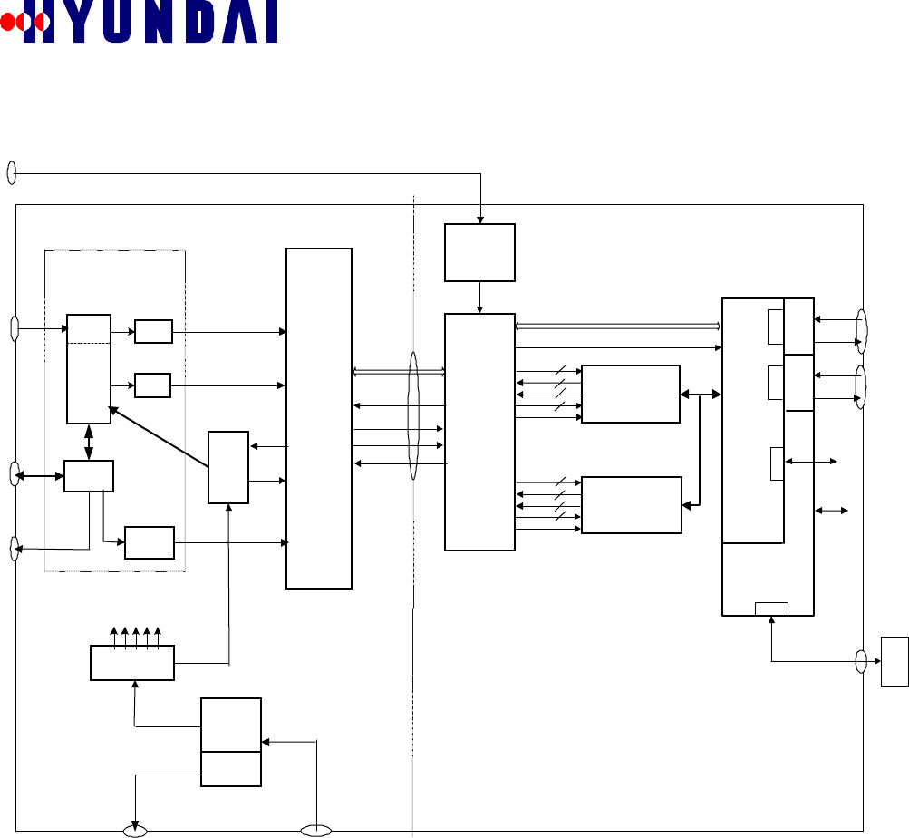
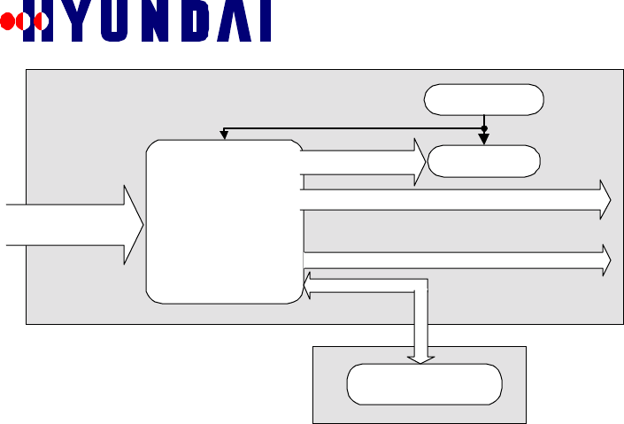
3.2.1 Functional Architecture
Figure.3.2-1 Functional Architecture
3.2.1.1 Transceiver Card (XCVC)
XCVC performs frequency conversion of transmitted and received signals, either RF to IF or IF
to RF, and the amplification of the signals, both transmitted and received. On the reverse link, it
amplifies the received weak signal sent by the mobile station, and changes the carrier frequency
to 4.95 MHz IF band. On the forward link, it takes the IF band signal, converts it to the active RF
carrier frequency, and then amplifies it to send through the antenna. In the Pico-BTS, only a
single CDMA frequency is being supported to reduce the size and to make the configuration
simple. Later, we can consider multi-FA Pico BTS as an option. In Pico BTS, XCVC and other
RF unit controlling functions are consolidated into BCPC.
3.2.1.2 Baseband Digital Card (BDC)
BDC plays a central role in processing the CDMA baseband signal. There will be two BDCs in
Pico BTS. Each BDC will support 16 Channel Elements. Major functionality of BDC is as
follows:
RX_AN
T
DPLX_AN
T
XCVC
IFRX
0
IFRX
1
IFT
X
PA
GPS ANT
BDC
BDC
BCPC
MPC860
(i960
)
DC to DC
Converter
s
BBDC
ACDC
110 / 220
VAC
RFU BBU
DPLX
RFFE
D
TP
C
4
8
rx
d
tx
d
ct
li
n
t
8
4
ES,
SCLK
D
MPor
t
1PPS, 10M,
ES,
SCLK,TOD
RXRF
1
RXRF
0
TxI
F
BAC
tx
d
ct
l
rx
d
i
n
t
ES,
SCLK
RBPF
D/C
GPRP
+5V +12V -12V +3.3V +7.5V
Addr, Data,
Cotro
l
Addr, Data,
Cotrol
Alarm
s
TX_PW
RMonito
r
Back-u
pBatter
y
Port
Alar
m I/O
Port
A
CPowe
r
10MH
z
TO
D
(i960
)
SC
C
SC
C
AC to DC
Converte
r
Charge
r
+27V
+48V
LNA
LNA
RX+,RX
-
TX+,TX
-
T1/E
1
Handle
r
T1/
E
1
TRK
1
SC
C
RX+,RX
-
TX+,TX
-
T1/E
1Handle
r
T1/E
1TRK
2
SC
C
Surge
Protector
Surge
Protector
Surge
Protector
PWR
DET

Rev: 1.0
Hyundai Electronics Confidential and Proprietary
15
" Signal Processing of CDMA baseband in forward and reverse link.
" Processing of messages relevant to call control and maintenance
3.2.1.3 BTS Control Processor Card (BCPC)
BCPC is the main controller for the Pico-BTS. Its main functions are call control and
maintenance of Pico BTS. Functionality of BCPC is described briefly:
" Contains software for call control and maintenance
" Download the software into BDC at power up
" Processing of call setup and tear-down/ handoff
" Collects information for all hardware faults
" Control RF network operation
" Communication with BSC (CCP, TSB) for report and reception of upper-level control
" OPAID - Operational AID, such as alarm indications, ...
" BIU - Backhaul Interface Unit, this is the T1/E1 interface between BSC and Pico BTS.
" Message routing - BCPC will route the messages within Pico BTS.
" RF unit controlling function
" Process of the TOD and 1PPS received from the GPS receiver.
3.2.1.4 GPRP, BAC Card
GPRP generates timing and frequency references for Pico-BTS. The ultimate reference comes
from the GPS. As other subsystems, the general functionality is similar to those of the existing
system. However, redundancy is not used.
Basic functionality is described as follows:
" Generates system clock (19.6608 MHz), Buffered 10 MHz, EVEN-SEC clock.
" Generates local clock in case of GPS failure
" Frequency conversion of baseband signal to/from 4.95MHz IF signal
3.2.1.5 Backhaul Interface Unit (BIU)
BIU performs the communication between the subsystems of Pico BTS, and it is also the gateway
to the BSC. Detailed architecture and functionality are described in chapter 4. In the Pico BTS,
BCPC will function as the gateway to BSC handling all messages transmitted/received to/from
BSC. BCPC includes the BIU.
3.2.1.6 Inter Module Communication (IMC)
In Pico BTS, the all other hardware modules are connected to BCPC through the point-to-point
serial connection forming a start network. The modules will communicate each other via this
serial connection. All messages will be transmitted in the HDLC format.
3.2.1.7 Power Subsystem Unit
The Pico BTS uses 120VAC or 220VAC as its power source. It is equipped with a rectifier, a
backup battery, and a distribution panel. The specification for the power subsystem follows:

Rev: 1.0
Hyundai Electronics Confidential and Proprietary
16
Table 3.2.1-1 Power Subsystem Units
Module Specification Comments
Rectifier Input : 120 VAC or 220 VAC
Output Voltage: +48 VDC
Output Current : Max 10 Amps
Input tolerance : 10 %
Size and weight limited
Battery
(Optional) Output : +48 VDC
Capacity : 10 Amps
Backup Time : 4 hours
Battery size and weight
requirements may limit
backup time.
DC-DC Converter Input : +48 VDC
Output : +5 V, +12 V, -12 V, +3.3 V, +7.5,
+27 VDC.
Power for the hardware circuits
3.3 System Interface
3.3.1 External Interface
3.3.1.1 Air Interface
The air interface conforms to EIA/TIA/IS-95-A..
3.3.1.2 Network Interface
The interface to BSC conforms to the current specifications between BSC and BTS of Hyundai’s
CELLULAR system.
3.3.1.3 Electric Power
The specification for the input electrical power is as follows:
" Input Voltage : 120 VAC or 220 VAC optional, single phase.
" Tolerance : ±10 %
3.3.1.4 Man-Machine Interface
The Pico BTS will have following MMI’s.
" A RS-232C port on the surface for portable PC connection.
" LED, RS-232C ports inside the cover, on each board.
3.4 System Availability, Maintenance, and Environmental Enhancement
3.4.1 System Availability
System down-time shall be no more than 10 minutes per year on the average, assuming a 2 hour
repair (replacing) time for any failure.
3.4.2 System Maintenance
The Pico BTS maintenance features shall be designed to minimize the effects of failures on
system performance and to provide technicians with the information and tools needed to identify
the troubled system easily.
3.4.3 Environmental Enhancement
3.4.3.1 Mountable Kits
The Pico BTS is designed to meet a complete range of extended environmental standards, such as
shock and vibration.
3.4.3.2 Convection Cooling
The Pico BTS uses natural convection cooling (heat sink). Major hardware components
generating heat such as CPUs shall be thermally treated to reduce the contribution to increase the
ambient temperature. The location of hardware shall be considered carefully from the thermal
point of view, so that heat-generating elements can be located outer and/or upper portion of the
cage.

Rev: 1.0
Hyundai Electronics Confidential and Proprietary
17
3.5 Pico-BTS Block Condiguration
3.5.1 Baseband Unit (BBU)
Figure 3.5.1-1 Base Band Unit
BDC
BDC
GPRP
BAC
BCPC

Rev: 1.0
Hyundai Electronics Confidential and Proprietary
18
3.5.2 RF Unit (RFU)
Figure 3.5.2-1 RF Unit
XCVC
BBDC
ACDC
HPA
LNA LNA
BPF DPLX
D/C
PDET
Rev: 1.0
Hyundai Electronics Confidential and Proprietary
19
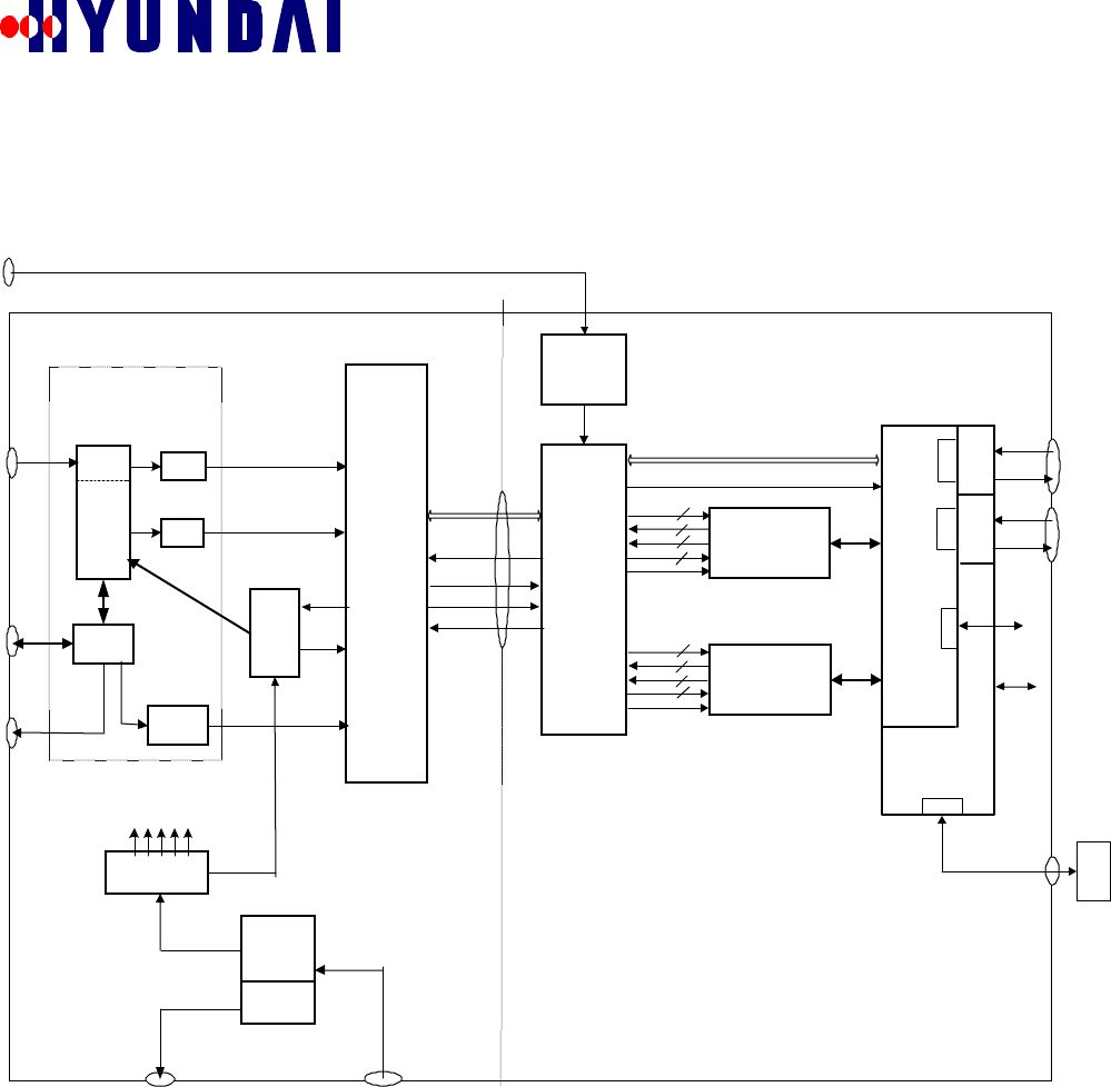
4. Hardware Structure and Functions
The system block diagram is shown again for better understanding of the hardware structure and
PBA names.
RX_ANT
DPLX_ANT
XCVC
IFRX0
IFRX1
IFTX
uPA
GPS ANT
BDC
BDC
BCPC
MPC860
(i960)
DC to DC
Converters
BBDC
ACDC
110 / 220 VAC
RFU BBU
DPLX
RFFE
DT
PC
4
8
rxd
txd
ctl
in
t
8
4
ES, SCLK
DM
Port
1PPS, 10M,
ES, SCLK,TOD
RXRF1
RXRF0
TxIF
BAC
txd
ctl
rxd
in
t
ES, SCLK
RBPF
D/C
GPRP
+5V +12V -12V +3.3V +7.5V
Addr, Data, C
otrol
Addr, Data, Cotrol
Alarms
TX_PWR
Monitor
Back-up
Battery
Port
Alarm
I/O Port
AC
Power
10MHz
TOD
(i960)
SCC
SCC
AC to DC
Converter
Charger
+27V
+48V
LNA
LNA
RX+,RX-
TX+,TX-
T1/E1
Handler
T1/E
1
TRK1
SCC
RX+,RX-
TX+,TX-
T1/E1
Handler
T1/E1
TRK2
SCC
Surge
Protector
Surge
Protector
Surge
Protector
PWR
DET
Figure 4.1-1 Hardware Functional Block Diagram
4.1 RF Subsystem
This section describes the RF subsystem which is composed of an RF Front End (RFFE), a High
Power Amplifier(PA), and a Transceiver(XCVC).
4.1.1 Functionality
The main functions of the RF subsystem are listed as follows:
• CDMA frequency assignment(FA).
• 4.95MHz IF frequency up-conversion to cellular forward path frequencies and cellular
reverse path frequencies down-conversion to 4.95MHz IF frequency.
• Providing software-controllable attenuators for cell blossoming, wilting and breathing.
Rev: 1.0
Hyundai Electronics Confidential and Proprietary
20
• Forward power maintenance: pilot calibration and transmit power tracking loop
functions.
• Diversity receive paths balancing.
• Reverse link gain control: providing a constant IF output over the operational dynamic
range through Automatic Gain Control (AGC).
• Providing RF related data for system performance monitoring.
4.1.2 Architecture
Figure 4.1.2-1 shows the overall architecture of the RF subsystem.
RX_ANT
XCVC
IFRX0
IFRX1
IFTX
PA
DPLX
RFFE
RXRF1
RXRF0
TxIF
D/C
Alarms
TX_PWR
Monitor 10MHz
DC to DC
Converter
DPLX_ANT
Synthesizer
Transmitter
Receiver0
Receiver1
RBPF LNA
LNA
Pwr
Det
Figure 4.1.2-1 RF Subsystem Architecture
4.1.2.1 RF Front End
The RF Front End (RFFE) consists of RX Front end and TX Front End.
4.1.2.1.1 RX Front End(RXFE)
The architecture of the RXFE is shown in Figure 4.1.2-2.
LNA
Duplexer
(IS <1.0dB)
Receive 0
Duplex
antenna
Rev: 1.0
Hyundai Electronics Confidential and Proprietary
21
LNA
RX BPF
(IS<1.0dB)
Receive1
Diversity RX
Antenna
(b)
Figure 4.1.2-2
Figure 4.1.2-2 RX Front End Architecture of (a) Duplex antenna, (b) Diversity RX antenna.
The RX front end has two kinds of receive paths: a duplex RX path and a diversity RX path. The
duplex RX path is composed of a duplexer, a low noise amplifier, and down-converter circuits.
The duplexer is used for sharing a transmit antenna with a receive path. The diversity RX path is
composed of a receive band pass filter, a low noise amplifier, and down-converter circuits.
4.1.2.1.2 Tx Front End(TXFE)
The architecture of the Tx Front End is shown in Figure 4.1.2-3.
Figure 4.1.2-3 Tx Front End Architecture
The Tx Front End consists of a duplexer, a directional coupler, a transmit band pass filter, and a
power detector. The major portion of the high power signal is sent to transmit antenna through a
duplexer, and a directional coupler. A small portion of the signal is coupled to the power detector
through the auxiliary port 1 of the directional coupler which monitors the output power level. A
duplexer should be used for sharing the transmit antenna with a receive path. A duplexer with
insertion loss less than 1.0dB should be used to minimize the transmit power loss.
High Power
Amplifier
Duplex
Antenna
Alarm & Control
Directiona
l Coupler
30dB
Coupling
To XCVC
From
XCVC
Duplexe
r
Power
Detector

Rev: 1.0
Hyundai Electronics Confidential and Proprietary
22
4.1.2.2 High Power Amplifier
The High Power Amplifier (PA) should have a minimum specification as follows:
Parameter Specification
Operating frequency 849 - 894 MHz
Gain / Max.Power 45 dB / 10 Watts
Adjacent Channel Power Rejection (ACRP)
(Pout = 10 W min. and CDMA BW =
1.23 MHz)
-47 dBc @f0±885kHz with Integration BW = 30
kHz
Spurious Suppression Outside Frequency
Block
a) Adjacent Channel Power Level
(Pout = 10 W min. and CDMA BW = 1.23
MHz)
b) Adjacent Channel Power Level
(Pout = 10 W min. and CDMA BW = 1.23
MHz)
-13 dBm max. @f0±1.25 MHz
with Integration BW = 30 kHz
-13 dBm max. @f0±2.25 MHz
with Integration BW = 1 MHz
Gain Variation vs. Frequency ±1.0 dB
Gain Variation over Temperature +1.0dB / -1.5dB
Return Loss 16 dB (Input and Output)
DC Input Voltage +27 V (Nominal)
DC Current 5.2 A max.
DC Power Dissipation 140 W max.
Operating Temperature -30o to +85o C (Base plate)
Alarms Over power, high temperature
Cooling Passive convection cooling
Ταβλε 4.1.2−1 ΗΠΑ Σπεχιφιχατιονσ
4.1.2.3 Transceiver
The transceiver (XCVR) consists of a transmitter (up-converter), two receivers (down-
converters), and a synthesizer. The transceiver should be realized as compact as possible.
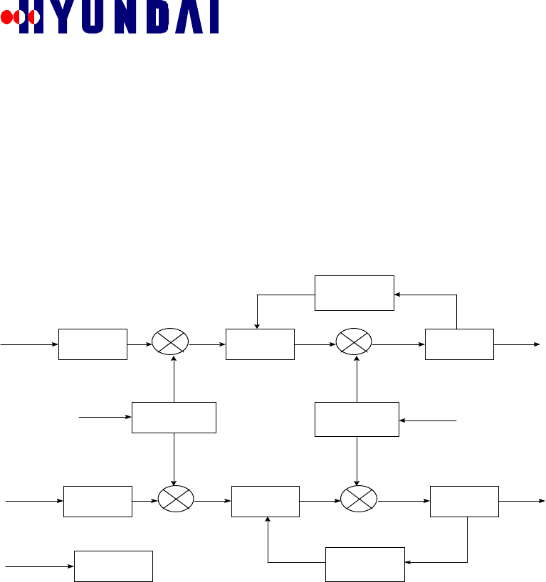
4.1.2.3.1 Up-converter (Transmitter)
A block diagram of a transmitter is shown in Figure 4.1.2-4.
Interface
C irc u itry
2nd IF
C ircu itry
Tx IF
(4.95 M H z)
1 s t IF
C irc uitry R F
C irc uitry
TxFE
LO 2 (Tx) LO 1 (Tx)
from R F
Synthesizer
Figure 4.1.2-4 Up-converter Block Diagram
Rev: 1.0
Hyundai Electronics Confidential and Proprietary
23
The up-converter accepts the 4.95 MHz signal, filters and attenuates the signal to a proper level,
then performs a frequency conversion to the 150 MHz IF. This frequency was selected so that a
common RF synthesizer could be used for both forward and reverse signal paths. Then it converts
the 150MHz IF frequency up to an assigned cellular band frequency. The first IF circuitry
includes filters, SAW filters, and PIN diode attenuators for forward link gain control and cell
blossoming, wilting and breathing. The frequency agile RF synthesizer may be used for the final
conversion.
4.1.2.3.2 Down-Converter (Receiver)
A block diagram of a down-converter is shown in Figure 4.1.2-5.
RF Input
C ircuitry
1st IF
C ircuitry
2nd IF
C ircuitry
RF Input
C ircuitry 1st IF
C ircuitry 2nd IF
C ircuitry
A m plifier/
Divider Fixed
Synthesizer
AGC
AGC
IF0 (4.95 MHz)
IF1 (4.95 MHz)
Interface
Circuitry
Figure 4.1.2-5 A Down-converter Block Diagram
The transceiver has two down-converters. Each down-converter has a low noise amplifier at the
first part of its input circuitry to maximize the receive performance. The first conversion circuit
provides the frequency agility for the receiver, which provides amplification and attenuation. The
RF signal is then down-converted to the first IF of 70 MHz. The first IF circuitry contains
matched filters and attenuators for automatic gain control (AGC). A fixed LO of 65.05 MHz is
used to convert the first IF at 70 MHz to 4.95 MHz. The second IF circuitry consists of filters,
amplifiers and AGC detectors.
4.1.2.3.3 Synthesizer
The synthesizer provides very fine reference frequency for the transmitter and receivers, and
covers all frequency range of American cellular band with 30KHz resolution. The synthesizer
circuit is implemented on the up-converter printed circuit board (PCB).
Rev: 1.0
Hyundai Electronics Confidential and Proprietary
24
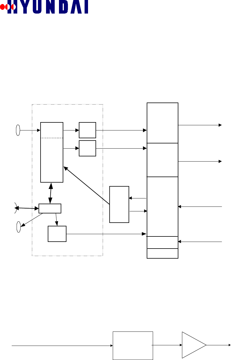
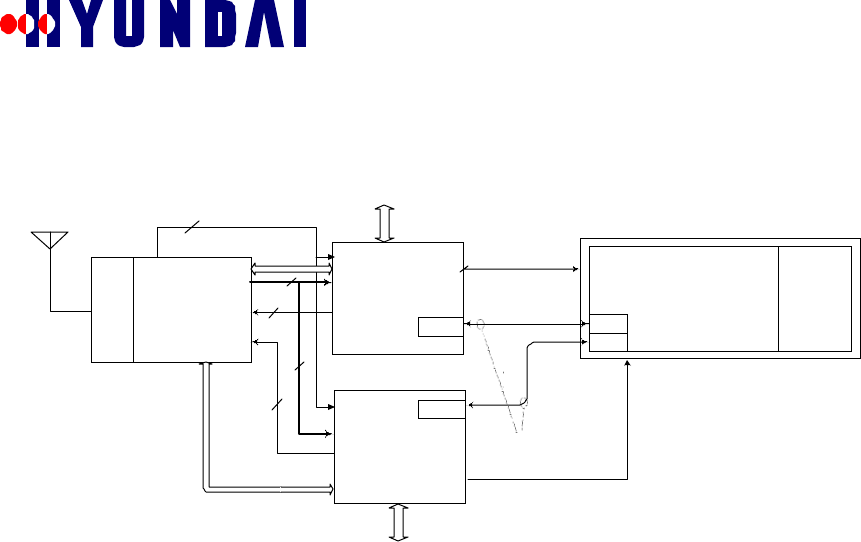
4.2 Pico-Baseband Digital Card (BDC)
4.2.1 Functionality
Figure Figure 4.2-1 illustrates the external interface between BDCs and other boards.
BAC
8
2
ESEC, SYS_CLK
BRXI0[3:0]
BRXQ0
[
3:0
]
8
Debug Por t
(RS232)
GPS Antenna BDC0
BDC1
Debug Por t
(RS232)
4BTXI 0
[
1:0
]
BTXQ 0[1: 0]
Int erface Signa ls
Int erface Signa ls
BCP
Controller T1 Handler
4
GPS
BCPC
BRXI1[3:0]
BRXQ 1[3: 0]
BTXI 1[1:0 ]
BTXQ 1[1: 0]
BD0_ cpu_faultN,
BD0_clk_faultN
BD0_ cpu_faultN,
BD0_clk_faultN
Figure 4.2-1 Major Interfaces of BDC
BDC’s major functions are as follows:
1. Transmits pilot, sync, paging, and forward traffic channel messages. Receives
access and reverse traffic channel messages.
2. Demodulates received CDMA I & Q signals from BAC.
3. Modulates the incoming voice/data packets from the T1 line and serially transfers to
the BAC.
4. Performs actions according to the commands of BCPC.
5. Exchanges traffic and control data with BCPC through a SCC port.
4.3 Pico BTS Control Processor Card (BCPC)
The BCPC is the main control processor in the pBTS structure. It has a role to interface and
communicate with other units and to process signaling messages for call management. It has
following capacity and functions:
• computing power: larger than 15MIPS.
• Status and alarm monitoring for all units in BTS.
• Storing the program and data from BSC for BCPC and BDC.
In terms of hardware, BCPC provides the following functions:
• Core Processing Unit,
• BSC Interface,
• BDC Interface,
• BAC Interface,
• XCVC Interface,
• GPRP Interface.
Rev: 1.0
Hyundai Electronics Confidential and Proprietary
25
Figure 4.3-1
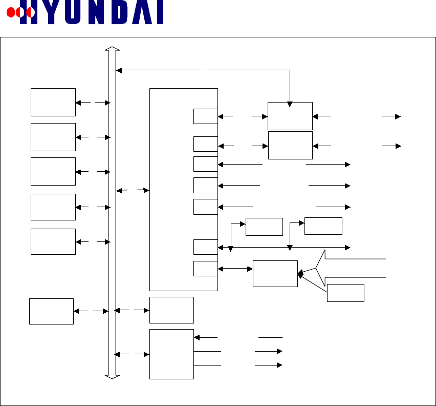
4.4 BTS Baseband Analog Card(BAC)
BAC has following functions:
• Digital summing of I & Q streams from two BDCs.
• Modulating digital-to-analog converted (DAC) baseband I & Q signals with 4.95 MHz I
& Q intermediate frequency(IF) carriers and sending to XCVC.
• Demodulating the received 4.95Mhz IF signal from XCVC into I & Q baseband signals,
analog-to-digital converting (ADC), and sending to BDCs.
• Providing the XCVC interface for BCPC.
• Providing GPS receiver processor (GPRP) interface for BTS and clock/frequency
distribution.
BOOT
FLASH
128-512KB
EXEC
FLASH-0
4MB
EXEC
FLASH-1
4MB
DRAM-0
4MB
DRAM-1
4MB
Local Bus
8
16
16
32
32
32
T1 Framer
BT8370
8
SCC HDLC T1 to remote BSC
SCC
SCC Debug Port
SCC HDLC to DM port
SMC UART to GPS receiver
I2C
TEMP
Sensor
ID
EEPROM
UART
16C550
8
EPLD
EPM7128
8TTLIN[11:0]
IRQIN[11:0]
TTLOUT[23:0]
ADC
MAX192
MPC860
SPI
Humidity
Sensor
Voltages,
Other monitor signals
T1 Framer
BT8370
HDLC T1 to other BTS
BDCs
8
Rev: 1.0
Hyundai Electronics Confidential and Proprietary
26
Figure 4.4-1 Overall Functional Block Diagram of BAC
4.5 GPS Receiver Processor (GPRP)
The Global Positioning System Receiver Processor (GPRP) derives accurate clock for the BTS
system. It generates 10 MHz clock , System Clock 19.6608 MHz, 1 Pulse Per Second (1PPS) and
Even Pulse Per 2 Seconds (EPP2S). Time of Day (TOD) information in ASCII code derives via
null modem serial port. The GPRP is self-sustained module that combines a GPS receiver,
double-oven precise oscillator and microprocessor. The GPRP provides time outputs
synchronized with the GPS time and frequency accuracy of better than 1x10-11, averaged over 24
hours. When no satellites are being traced (holdover), the time output drifts less than +/- 7
microseconds in 24 hours and GPRP delivers clocks with accuracy of +/-3x10-10 over a -20°C to
+70° temperature range. At first startup GPSRP performs 24 hours survey to determine the
antenna position and to discipline the frequency oscillator. The GPSRP provides reliable
reception with the remote GPS antenna.
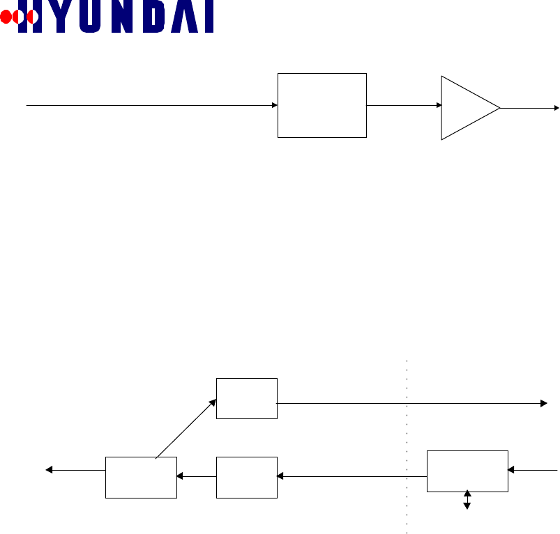
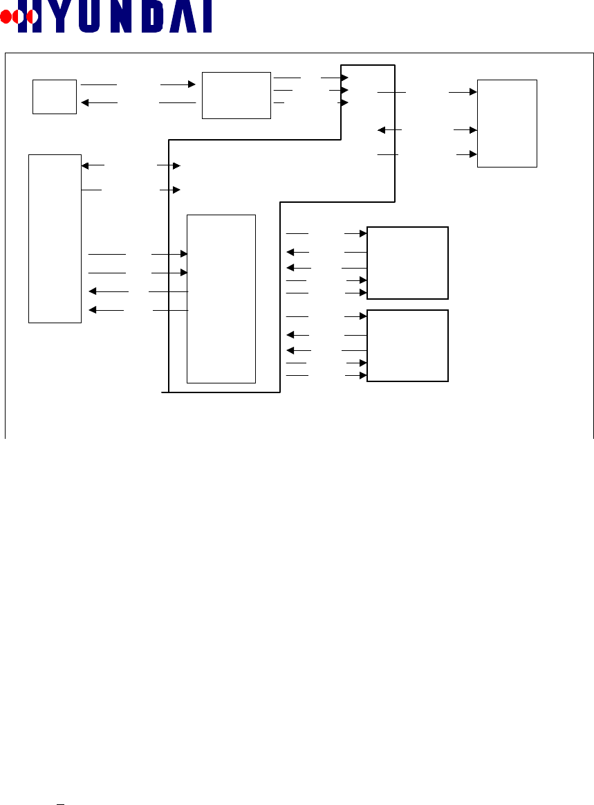
4.6 Power Supplies (ACDC, BBDC)
The ACDC converts the 110/220 (nominal) input to +48VDC. BBDC converts +48Vdc to
+27Vdc, +12Vdc, +5Vdc, and +3.3Vdc. ACDC supports optional battery backup through an
external port on the housing. Seamless power switching from AC input power to back up battery
power is achievable through the internal control circuitry which constantly monitors the DC
output of the +48Vdc power supply and battery. If input power or power supply failure
occurred, the internal circuitry automatically controls the relay to switch from input AC power to
the back-up battery without glitch.
IF-
baseband
mod/
demod
BAC
GPRP
RXI[3:0]
RXQ[3:0]
ES,SCLK
PERR_I/Q
CNTL/4
TXI[1:0]
TXQ[1:0]
BDC0
RXI[3:0]
RXQ[3:0]
ES,SCLK
PERR_I/Q
CNTL/4
TXI[1:0]
TXQ[1:0]
BDC1
1PPS,ES
SCLK,10MHZ
TOD
DIGITAL IF
ES,10MHZ
1PPS,TOD
ADDR,DATA,
CSn,R/W,
INTRn,..
ADDR,DATA,
WEn,OEn
Analog monitor
Analog monitor
RXIF1
RXIF2
TXIF
10MHZ
GPS signal
5V feeding
XCVR
GPS
Ant.
BCPC
Rev: 1.0
Hyundai Electronics Confidential and Proprietary
27
Φιγυρε 4.6−1 Φυνχτιοναλ Βλοχκ ∆ιαγραµ οφ τηε Ποωερ Συππλιεσ
4.7 Mechanical / Thermal Design
4.7.1 Background
• The mechanical / thermal design will comply with all agency (NEMA, ANSI, FCC
and UL) requirements for telecommunications equipment designed for outdoor use.
• It will also be lightweight, compact and easy to install.
4.7.2 Mechanical Characteristics / Requirements
• Size: Less than 22”(W) x 28”(H) x 12”(D).
• Weight: Less than 130 lbs.
• Material: Aluminum base and heat sink, structured foam (or equivalent) cover.
• Color: Blue and white (to conform with other Hyundai BTS).
• Mounting Locations: Pad, pole, wall or vault.
4.7.3 Thermal and Environmental Characteristics / Requirements
• Natural conduction and convection cooling, no fans.
• Heat pipes will be used when necessary for additional heat transfer.
• Outside ambient operating air temperature to be -30° to +50° C.
• Outside ambient humidity to be 5% to 95%.
• Solar load to be 70W/sq. ft.
• Internal heat load to be < 300W.
4.7.4 Design Strategies
Since the BTS has high power consumption and strict operational, environmental and thermal
design requirements, the mechanical / thermal design has three major steps. These steps are Initial
estimation; System level design and simulation; and Component and system level testing.
4.7.4.1 Initial Estimation
• Collect all thermally related information as it becomes available such as total system
power, power consumption of each PCB and component, heat source location and
power, etc. Use estimates where information is not yet available.
• Use heat transfer equations, thermal analysis tools(Flotherm, etc.), catalogs, related
experience, etc. to estimate the major components temperature rise based on current
design and choose suitable size and cooling system equipment (heat sinks, heat pipes,
etc.).
BBDC
BCPC
AC/DC Converter
&
Battery Charger
Power Up
Reset
+48Vdc
Status LEDs
Display Block
Data and Control
110/220 Vac
Back-up Battery
Status (2 TTL Outputs)

Rev: 1.0
Hyundai Electronics Confidential and Proprietary
28
4.7.4.2 System Level Design and Simulation
• Use mechanical solid design software tool (i.e. Pro/Engineer) to create entire BTS
mechanical system which includes enclosure and cover design, heat sink and heat
pipe locations and mounting design and components layout and system packaging.
• Use thermal design software tool (i.e. Flotherm) to simulate thermal model and do a
complete system level analysis in order to eliminate possible problem areas and make
design changes before prototypes are built. Analysis will include system temperature
distributions, air flow patterns, components temperature rise and hot spot
temperatures.
4.7.4.3 Component and System Level Testing
Based on the designed enclosure and mechanical layout, set up the system and conduct the
necessary mechanical and thermal testing required to assure compliance with all the necessary
requirements.
5. SOFTWARE DESCRIPTIONS
The software functions that will be provided may be divided into the following major categories:
• Call Processing functions; such as, call setup, call clearing, traffic handling, database
updating.
• System maintenance functions; such as, diagnostics, software download, hardware device
status monitoring, alarm reporting.
• System performance monitoring functions; such as, performance statistics gathering, overload
monitoring.
• Board boot up, and initialization.
• Board diagnostics, low level debug port support.
• Low level communications support, this includes initiating software download from the
BCPC or the CCP.
5.1 Pico BTS Control Processor Card (BCPC)
The BTS Control Processor Card (BCPC) is the hardware module whose primary function is
providing call control and maintenance of Pico BTS. There are twelve software blocks running in
the Pico BTS Control Processor Card which may be divided into the following major categories.
• Call processing control message handling between BSC and MS, which includes Paging
Channel messages, and Access Channel Messages.
• System Maintenance functions; such as, resource management, fault management, data
access management, status handling, processor loading, and diagnostics.
• Site alarm handling and reporting, this includes intrusion, temperature, humidity, AC power,
battery, vibration, etc..
• The Radio Frequency Unit control function.
• Processing of the Time Of Day (TOD) message and 1 Pulse Per Second interrupt received
from the GPS receiver.
5.1.1 Functional Overview
The primary responsibility of the Pico BTS Control Processor Card Controller is to provide call
processing functions between BSC and Mobile Stations. This is accomplished by exchanging call
control information associated with call setup, call clearing, and handoff between BCPC software
blocks and BSC via Backhaul Interface Unit. BCPC software blocks also exchange call control
information with Mobile Stations, via the pBDCX, to perform call processing related functions.
Following is a list of functions that will be provided by the BCPC software blocks.

Rev: 1.0
Hyundai Electronics Confidential and Proprietary
29
1. Call Processing - The BCPC Call Control block exchanges call processing control
information regarding call setup, call clearing, handoff with the BSC, and the pBDCX.
2. Channel Element Management - Upon receiving commands from the BSM, the BCPC
software blocks will send a command the pBDCX to setup the overhead channels, and traffic
channels. This includes restoring, and removing individual channel elements, switching to
standby overhead channels, adjusting RF output power gains, etc..
3. Device Status - The BCPC Status Handler block performs periodic status check of all
hardware devices in the Pico BTS, and reports exceptions to BSM.
4. Diagnostic - The BCPC software blocks provide functions to process diagnostic requests
from the BSM.
5. Resource Management - The BCPC Resource Management block performs resource
management functions as requested by BSM.
6. Device Configuration Database - The BCPC software blocks manage local copy of device
configuration database and reports any changes to the BSM.
7. Controlling the RF unit including Transceiver Control Unit (XCVC), RF Front End
Unit(RFFE), and Power Amplifier(PA).
8. The GPS receiver interface specific functions, which include:
◊ Processing the Time-Of-Day(TOD) message received from GPS receiver
◊ Processing the 1PPS interrupt, which includes the generation of the system time to
BDC at the even second.
9. Alarms - The BCPC software blocks monitors and manages alarm conditions from all local
hardware devices and physical environments. All alarm conditions will be reported to BSM.
10. Software Download - The BCPC software will download the software into BDC upon power
up or receipt of a request.
11. Debug Command Process - The BCPC software blocks will process commands received from
the local debug port, which includes:
• UI Support - Displays diagnostic menu on the console, and reads the input from the
operator.
• Parsing and processing the commands entered by the operator.
• Displaying the results on the console.
12. Performance Statistics Gathering - BCPC software blocks gather performance statistics and
forward it to BSM.
5.1.2 BCPC Boot Software (pBCPCb)
The BCPC boot software (pBCPCb) resides in the boot flash memory and receives control of the
processor on power up or reset. The primary function of the pBCPCb is to initialize the BCPC
hardware.
The pBCPCb provides the following functions:
• Initial board diagnostics via the Power On Self Test (POST)
• Debugging capabilities via the “PC” RS232 port.
• Initialization of the T1/E1 port for communication with BSC.
• Sending the software download request to the CCP to load the on-line software.
• Initiating the Pico BTS on-line software.
5.1.3 BCPC Software Architecture Overview
The pBTS Control Processor Card consists of twelve (12) software blocks, various Interrupt
Service Routines including Backhaul Interface Handler, TOD Interrupt Handler, 1PPS Interrupt
Handler, and the operating system. The blocks communicate with each other using the Inter-Task
Communication mechanism provided by the Sylos real time operating system. Communication
with external modules is through Inter Module Communication Handler.

Rev: 1.0
Hyundai Electronics Confidential and Proprietary
30
pRMX
Resource Management Block
Operating System
pCOX
Call Control Block
pUIX
User Interface Block
Other Interrupt
Service
Routines
IMC
Handler
pHFMX
H/W Fault Managment Block
pRAX
Resource Allocation Block
pDIAX
Diagnostics Block
pDAX
Data Acess Mgmt Block
pPLX
Loader Block
pVCX
Transceiver Control Block
Backhaul
Interface
Handler
TOD
Interrupt
Handler
1PPS
Interrupt
Handler
pRICX
GPS Reciver Control Block
pMMX
Measment Block
pSHX
Status Handler Book
Figure 5.1.3-1 BCPC Software Architecture
5.1.4 Interfaces
This section describes the interface among the BCPC software blocks and with other external
modules.
5.1.4.1 External Interface
• Interface with BSC/BSM
The BCPC will communicate with the BSC/BSM via the Backhaul Interface Handler, which
is described in section 5.5. The existing Gigacell IPC addressing scheme will be used for
backward compatibility. Backhaul Interface Handler will format individual packet suitable
for T1/E1 transmission to BSC/BSM. Conversely, Backhaul Interface Handler will de-format
individual packet received from the BSC/BSM and forward the packet to the Inter Module
Communication handler, which will send the packet to the destination whose address is
specified in the destination address field.
• Interface with pBDCX
The BCPC software blocks will communicate with the pBDCX via the Inter Module
Communication mechanism described in section 5.4. The IPC addressing scheme currently
implemented in the Gigacell Base Station will be used for the Inter Module Communication.
5.1.4.2 Inter-Task Communication
The inter-task communication among the BCPC software blocks is accomplished using Inter
Module Communication mechanism described in section 5.4. The IPC addressing scheme
currently implemented in the Gigacell Base Station will be used. The application software block
will send an IPC message to the OS using sendsig(). The OS will check the destination address
specified in the IPC header. If the specified destination address is the address assigned to the local
module, then the OS will notify to the local task who is registered with the specified signal ID. If
the specified address is the one assigned to a remote module, then the OS will send the message
to the remote module via the serial connection or the backhaul interface.
Rev: 1.0
Hyundai Electronics Confidential and Proprietary
31
5.1.5 Software Blocks
As mentioned previously, the pBTS Control Processor consists of twelve software blocks and the
interrupt service routines. In this section, the functions of each software block are described.
5.1.5.1 pBTS Call Processing eXecutive(pBCOX)
The Pico BTS Call Processing consists of two major components. The Pico BTS Configuration
Management (BCM) and Call Processing (CP). CP performs various call processing functions to
ensure the proper communication between MS and BSC. The BCM maintains the entire
subsystem configuration within Pico BTS.
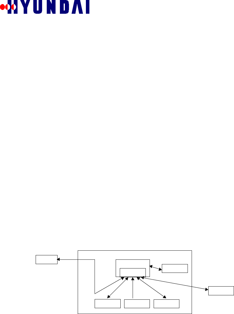
5.1.5.1.1 Pico BTS Configuration Management (BCM)
The Pico BTS Configuration Management maintains all the subsystem configuration within the
Pico BTS.
The BCM provides the following functions:
• Initializes configuration parameters, flags, and timers that will be used for the configuration
management.
• Update its configuration and display new configuration information through the debug port
when device status changes.
• Registers the configuration signals that will be received from other devices.
• Initializes Pilot and Sync channel and starts Pilot and Sync channel processing.
• Initializes Paging channel and activates Paging channel processing.
• Sends report to pBRMX during parameter change.
• Sends report to pBSHX for device status.
• Sends CDMA channel list report to BSM.
• Performs channel card remove/restore operation.
• Performs forward power management.
5.1.5.1.1.1 BCM Software Interface
The BCM, which is part of pBCOX, uses signals described in the previous section to exchange
configuration data with the following software blocks and devices:
Figure 5.1.5-1 BCM external interface diagram
5.1.5.1.2 Call Processing (CP)
The Pico BTS Call Processing complies with EIA/TIA/IS-95-A. It processes messages that flow
between MS and Pico-BTS as well as those between Pico-BTS and BSC. The different types of
message are described bellow:
• A-bis Messages
pBCOX
BCM
p
BDC
p
BVCX
p
BSHX
p
BRAX
BSM
p
BRMX

Rev: 1.0
Hyundai Electronics Confidential and Proprietary
32
A-bis Messages are Hyundai proprietary messages that are used between BSC and
Pico-BTS through T1/E1 interface. Pico-BTS shall format A-bis Messages and forward
to BSC. Pico-BTS will also de-format the received A-bis Messages and deliver to the
proper destinations.
• CAI Messages
CAI Messages are the messages used between Pico-BTS and MS through Paging,
Access, Sync, and Traffic channels. CAI Messages comply with EIA/TIA/IS-95-A.
The channel elements format CAI Messages and send to MS. Channel elements de-
format the received CAI Messages and deliver to proper destinations. Pico BTS
complies with the Acknowledgment Procedures as defined in EIA/TIA/IS-95-A.
• Pico-BTS Internal Messages
Pico-BTS Internal Messages are proprietary messages, which are used within the Pico-
BTS between the different subcomponents via the Inter Module Communication bus.
Call Processing consists of CP initialization and CP related activities. Call Processing provides
the following functions:
• CP initialization:
1. Initializes nodes address.
2. Initializes call state machine, Layer 2 parameters and device data.
3. Initializes registration information and sets up registration timer.
4. Initializes pages count, handoff count, and release reasons.
5. Resets measurement data.
6. Initializes CP parameters, and test call information.
7. Registers user commands such as pBCOX Menu, display device configuration and call
information etc.
8. Activates Layer 2 timer.
9. Activates paging message timer.
• CP activities:
10. Registers signals which are sending/receiving to/from BSC, other devices or internal
tasks.
11. Performs normal calls for origination and termination side.
12. Performs traffic channel assign when handoff occurred.
13. Performs registration procedure.
14. Performs internal call state machine.
15. Performs service configuration and negotiation.
16. Processes statistics for call processing.
17. Performs supplementary services.
18. Performs configuration and parameters update.
19. Performs simulation and message trace for maintenance purpose.
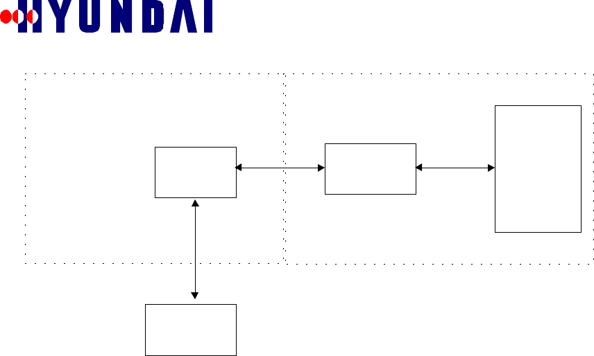
5.1.5.2 pBTS Resource Management eXecutive(pBRMX)
The Pico BTS Resource Management loads the Pico BTS common data received from the BSM
via CCP (CRMX), processes the MMI commands, updates PLD, retrieves hardware alarm data
upon request, sends alarm data to pBHFMX, and sends the request for changing channel elements
to CRMX when requested by pBCOX or pBRAX. It also provides functions to display all Pico
BTS related PLD data.
Rev: 1.0
Hyundai Electronics Confidential and Proprietary
33
Figure 5.1.5-2 pBRMX external interface diagram
The pBRMX provides following functions:
• Loads the common data from the BSM - Below is a list of the common data:
◊ Pico-BTS configuration and status data.
◊ Sector configuration and status data.
◊ CDMA channel ID list data.
◊ T1/E1 configuration and status data.
◊ Subcell configuration and status data.
◊ OTA system parameters.
After completely loading the common data, pBRMX will send the end of loading message to
the BSM and pBPLX.
• Processes the MMI commands received from BSM - The commands are:
◊ Blocking/unblocking Pico-BTS resources.
◊ Adding/removing the neighbor set.
◊ Updating the common data and local data in PLD.
• Processes channel element configuration change requests - This is requested from pBCOX or
pBRAX.
• Processes hardware alarm requests - pBRMX receives request for updated alarm data from
pBHFMX, retrieves the data and sends the data to pBHFMX.
• Displays PLD data by debugging port.
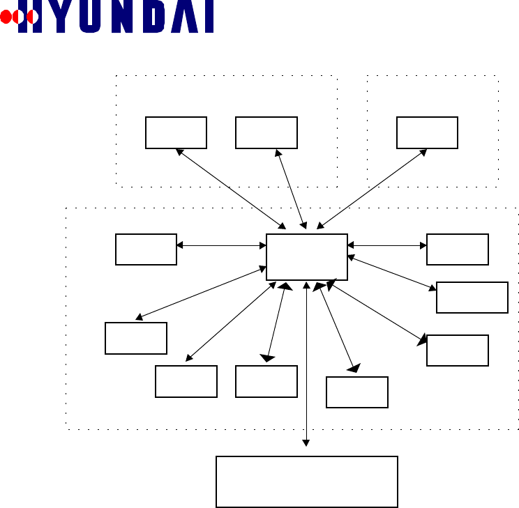
5.1.5.3 pBTS Status Handler eXecutive(pBSHX)
The pBTS Status Handler manages pBTS hardware device status, controls the pBTS overloading
to avoid abnormal status, and periodically checks the resource utilization. The pBSHX also
provides functions to handle manual diagnostics of pBTS hardware device.
pBRMX
CRMX
pBSHX
pBCOX
pBRAX
pBHFMX
pBDIAX
pBPLX
CCP BCPC
BSM
Rev: 1.0
Hyundai Electronics Confidential and Proprietary
34
BCPC
BSM
Figure 5.1.5-3 pBSHX external interface diagram
The pBSHX provides following functions:
• Main function
◊ Initializes the global variables.
◊ Registers signals.
◊ Processes MMI commands and sends results to BSM.
• BDC Related Functions
◊ Monitors BDC
◊ Processes channel element software alarm.
◊ Processes overhead channel status changes.
◊ Processes traffic channel status changes.
• RFC Related Functions
◊ Processes PA status changes.
◊ Processes XCVC (RF Transceiver) status changes.
◊ Processes Up converter and Down converter status changes.
◊ Processes RFFE(RF Front End) status changes.
• Overload Monitoring
◊ Initializes overload data.
pBSHX
pBCOX
pBRMX
pBRAX
pBDIAX
STMX CSHX
CCP
pBTS Devices
(BDC )
FLMX
pBDAX
pXVCX
pBRICX
pBPLX

Rev: 1.0
Hyundai Electronics Confidential and Proprietary
35
◊ Monitors the traffic channel and processor overload status.
◊ Determines the traffic channel overload level.
◊ Reports overload conditions to BSM.
◊ Rejects calls when overload condition is detected.
• T1/E1 Monitoring
◊ Monitors and handles T1/E1 status.
• pBTS Hardware Device Manual Diagnostics
◊ Displays BDC current status.
◊ Displays BDC fault registers
◊ Sends BDC keep alive message and prints the results.
◊ Restart BDC test.
◊ Restart CE test.
◊ Displays pBAC current status.
◊ Displays pBAC fault registers.
◊ Blocks pBAC / Unblocks pBAC.
◊ Initializes Phased Locked Loop in pBAC.
◊ Displays the status of the GPS receiver.
◊ Displays XCVC status.
◊ Displays PA status.
◊ PA disable test.
◊ PA enable test.
◊ PA restart test.
5.1.5.4 pBTS Diagnostic eXecutive(pBDIAX)
The pBDIAX is the diagnostic component of the BCPC. It processes diagnostic commands
received from the BSM. The pBDIAX may also be invoked through local debug port. If invoked
through the debug port, it displays two test choices. The first test is to test the channel elements
using KA (keep_alive), and the second one is BIT (built_in_test).
pBDIAX will provide the following functions:
• T1/E1 diagnostic tests.
• CE diagnostic tests.
• CE KA (keep_alive) test.
• Monitoring BCPC overload status.

Rev: 1.0
Hyundai Electronics Confidential and Proprietary
36
ACE
pBDCX
TCE
PCE
PSCE
pDIAX
Main
T1/E1
Handler
CCP
Φιγυρε 5.1.5−4 πΒΤΣ ∆ιαγνοστιχσ εξτερναλ ιντερφαχε διαγραµ
Diagnostic requests are stored in individual arrays for each equipment type. The arrays are:
• Pilot and SYNC channel element array (psce_req_table[]),
• Paging channel element array (pce_req_table[]),
• Access channel element array (ace_req_table[]),
• Traffic channel element array (tce_req_table[]), and
• Channel control array (cc_req_table[]).
5.1.5.5 pBTS Processor Loader eXecutive(pBPLX)
The pBTS Processor Loader handles downloading software from the CCP to the BCPC processor,
and downloading software from the BCPC to the pBDCX processor.
The pBPLX has the following functions:
• Initializes global parameters and loading table.
• Registers signals.
• Loads BCPC software blocks, and pBDCX.
• Updates subsystem loading status.
• Performs loading error report.
• Performs checksum for data/text transactions.
5.1.5.6 pBTS Data Access eXecutive(pBDAX)

Rev: 1.0
Hyundai Electronics Confidential and Proprietary
37
The pBTS Data Access task provides access methodology to the pBTS PLD database. The
pBDAX provides various database access functions to access PLD.
The pBDAX has the following functions:
• Sets up PLD database access function addresses.
• Provides select, add, delete and update functions to access PLD.
• Provides index and sequential access methods to access PLD.
5.1.5.7 pBTS Resource Allocation eXecutive(pBRAX)
The pBTS Resource Allocation allocates and deallocates the pBTS resources for call related
functions, stores statistical data for measurement and retrieves device status for status handler.
When the pBCOX (Call Control) processes normal call setup or handoff, the pBCOX requests the
pBRAX to provide the available resources. The pBRAX will try to allocate the available resource
upon receiving the request. If the pBRAX allocates the resources successfully, it returns a
successful message to the pBCOX. If the pBRAX cannot allocate the required resources
completely, the pBRAX deallocates all allocated resources associated with the current request,
and sends the error code to the pBCOX.
pBRAX provides the following functions:
• Normal Call and Handoff Related Functions
◊ Carrier selection.
◊ Allocation / deallocation of the frame offset.
◊ Allocation / deallocation of CDMA channel index.
◊ Allocation / deallocation of power gain.
◊ Allocation / deallocation of Walsh code.
◊ Allocation / deallocation of traffic channel.
◊ Processes handoff status message received from pBCOX.
• RF and CE Related Functions
◊ Initializes global variables which are used to store CEs data.
◊ CE resource allocation / deallocation when requested
• T1/E1 Related Functions
◊ Retrieves current T1/E1 handler data and sends the data together with T1/E1 utilization to
pBMMX.
• STATISTICS Related Functions
◊ Displays traffic statistics and system performance statistics as requested by pBMMX.
• Device Configuration
◊ Update configuration data of each device.
5.1.5.8 pBTS Measurement eXecutive(pBMMX)
The pBTS Measurement (pBMMX) handles statistical measurements. It starts or stops the pBTS
statistical measurement upon receiving request from the BSM. The pBMMX also provides
functions to display the statistical data and to simulate statistical measurements. Upon receiving
the request, the pBMMX starts taking the specified statistical measurements based on received
message id. The pBMMX will collect and store the statistical data and send them to the BSM via
CMMX. The statistical data include call performance statistics, T1/E1 statistics, air interface
statistics, CEs statistics and the BCPC processor statistics.
pBMMX provides following functions:

Rev: 1.0
Hyundai Electronics Confidential and Proprietary
38
• Processes messages received from the BSM to start or stop taking statistical measurements.
The pBMMX requests and receives the statistical data from following software blocks or
devices:
◊ Air interface statistics from the pBDCX.
◊ T1/E1 statistics from BIH.
◊ CEs statistics from the pBCOX.
◊ Performance statistics from the pBRAX which generated by the pBCOX.
◊ The BCPC processor statistics by calling OS library function.
• Displays traffic statistics.
• Displays the Pico-BTS performance data.
• Displays T1/E1 traffic statistics.
• Displays error statistics for air interface.
• Displays common air interface statistics.
• Simulates statistical measurements.
5.1.5.9 XCVC Control eXecutive (XVCX)
The Pico XCVC Control eXecutive (pXVCX) is a software block that resides in the BCPC. The
major functionality provided by pXVCX is controlling the RF unit including Transceiver Control
Unit(XCVC), RF Front End Unit(RFEE), and Power Amplifier(PA). This functionality is
provided by the dedicated control board called, TCCA, in the Gigacell.
However, in the Pico BTS, the RF unit controlling functionality is consolidated into the BCPC.
This change has been made in order to reduce the number of boards and, as a result, reduce the
power consumption. In Pico BTS, the BCPC will control the RF unit through the parallel
interfaces.
5.1.5.9.1 Functional Overview
As mentioned earlier, the primary functionality of the pXVCX is controlling the RF unit
including Transceiver Control Unit (XCVC), RF Front End Unit (pRFEU), and Power Amplifier
(PA). In this section, the functions provided by the pXVCX are described:
1. Attenuator/AGC Configuration
Three attenuators will be allocated to each XCVC, one for the transmit path and two for the
receive path. The pXVCX will configure the attenuators of a XCVC based on the information
specified in the XCVC configuration table 1) at the initialization time, 2) upon receipt of
“RCONF” command from the diagnostic port, or 3) upon receipt of a command from BCPC.
The XCVC may be configured to perform the one of the following functions:
• Normal Operation:
Configuration of the XCVC for the normal operation include:
◊ Configuration of the attenuator for transmit path
◊ Configuration of the attenuators for receive path
◊ Configuration of Frequency Synthesizer
• Reverse Power Management:
• Reverse Capacity Management:
• Transmit Adjust:
Adjust the transmit power.

Rev: 1.0
Hyundai Electronics Confidential and Proprietary
39
2. Frequency Configuration: Configure the register of the Frequency Synthesizer to set the
transmit and receive frequency.
3. Initialization and management of the local devices; such as, the RF Transceiver (XCVC), the
RF Front End (RFFE), and the Power Amplifier (PA) via the parallel interfaces.
4. Diagnostic and fault management of the XCVC, the pRFFE, and the pPA.
5. Process the commands received from the pBCOX.
6. Execute the diagnostic commands entered by the user via the RS232 port and display the
results. This function includes validating the command, executing the command, and
displaying the result on the console.
5.1.5.10 Pico GPS Receiver Controller eXecutive (pGRICX)
The Pico GPS Receiver Controller eXecutive (pGRICX) is a software block that resides in the
BCPC. The major functionality provided by pGRICX is processing One Pulse Per Second (1PPS)
and Time Of Day (TOD) received from the GPS receiver, generating the system time to other
module, and monitoring the status of the GPS receiver. This functionality is provided by TFCA,
which is a Motorola 68302 based board, in the Gigacell. However, in the pBTS, the functionality
to process the TOD and 1PPS is consolidated into the BCPC in order to simplify the architecture
and, as a result, reduce the power consumption.
5.1.5.10.1 Functional Overview
The primary functionality of the pGRICX is processing the 1PPS and TOD received from the
GPS receiver. In this section, the functions provided by the pGRICX are described in detail:
1. Processes 1 PPS Received from the GPS receiver. Upon receipt of 1 PPS, pGRICX will send
the system time to BCM block and pBDCX at even second.
2. Checks the 1 PPS existence. If 1 PPS is missing for more than 10 times, then pGRICX will
generate an alarm.
3. Processes the TOD received from the GPS receiver via the serial port.
4. Validates the TOD format.
5. Checks the TOD existence. If the TOD is missing for more than 10 times, then pGRICX will
notify to BSM.
6. Processes the commands received from the pBCOX.
7. Executes the diagnostic commands entered by the user via the RS232 port and display the
results. This function includes validating the command, executing the command, and
displaying the result on the console.

Rev: 1.0
Hyundai Electronics Confidential and Proprietary
40
5.1.6 Interrupt Service Routines
The following interrupt service routines will be implemented in BCPC to handle various
interrupts generated by the external/internal devices:
• Real Timer Clock Handler - This is used to update system time, performs timer related
functions.
• DMA Transmit Status - This includes three routines to handle DMA data transmit status.
One routine to signal DMA transmit completed successfully, the second routine to signal
DMA transmit error, the third routine indicates serial port (MPCC) transmit error.
• DMA Receive Status - This includes three routines to handle DMA data receive status. One
routine to signal DMA receive completed successfully, the second routine to signal DMA
receive error, the third routine indicates serial port (MPCC) receive error.
• Exception Handlers - This interrupt handles hardware-related failures on the BCPC.
• System Call Traps - BCPC software blocks uses Sylos as the real time operating system.
Sylos system calls are executed through the “trap” mechanism. All existing system calls in
the Gigacell will be supported in the pBTS.
• TOD Interrupt - To process the interrupt generated by the SMC1 upon receipt of the TOD
message from the GPS receiver.
• 1PPS Interrupt Handler - To process the interrupt generated upon receipt of the 1PPS from
the GPS receiver.
5.2 Baseband Digital Card (BDC)
The Baseband Digital Card (BDC) is the hardware module whose primary function is providing
the digital signal processing of the CDMA waveform within pBTS. Two different software blocks
will be run in the BDC, the Pico Baseband Digital Card Boot software (pBDCb) and the Pico
Baseband Digital Card eXecutive(pBDCX). The pBDCb, which resides in the boot PROM, is to
boot the BDC at the power up. The pBDCX is the software block that will be stored in the
executable flash of BCPC. At the system initialization, the pBDCX will be downloaded into the
DRAM of BDC and executed there. The primary function of pBDCX is controlling the CDMA
Cell Site Modem (CSM) chips. This section describes the functional requirements and software
architecture of the pBDCX.
5.2.1 Functional Overview
The primary responsibility of the pBDCX is controlling the CDMA Cell Site Modem (CSM)
ASIC, which is a CDMA baseband modem for reverse link demodulation and forward link
modulation. It also processes the calls within the Base station Transceiver System (BTS) by
sending and receiving the control information associated with call setup, call clearing, and
handoff to/from the BCPC via the Inter Module Communication mechanism. The following is a
list of the functions that will be provided by the pBDCX:
1. Channel Element Configuration
At initialization time, the pBDCX configures each Channel Element based on the
configuration information received from the BCPC; thus, each Channel Element performs
one of the four functions, Pilot and Sync Channel, Paging Channel, Access Channel, and
Traffic Channel as follows:

Rev: 1.0
Hyundai Electronics Confidential and Proprietary
41
• Pilot and Sync Channel:
The configuration of the Pilot and Sync Channel consists of setting up interrupt
generation related to the Sync Channel data encoding, configuring the Long Code PN
generators, configuring the Reverse Link, and configuring the Forward Link.
• Paging Channel:
In order to configure to transmit a Paging channel from a single CSM to a single sector,
the pBDCX is required to set up interrupt generation related to the Paging Channel data
encoding, configure the Long Code PN generators, configure the Reverse Link, and
configure the Forward Link.
• Access Channel:
The Access channel configuration consists of setting up interrupt generation related to the
Access Channel data decoding, configuring the Long Code PN generators, and
configuring the Reverse Link.
• Traffic Channel:
In order to transmit and receive a Traffic channel, the pBDCX needs to set up interrupt
generation related to the Traffic Channel data encoding/decoding, configure the Long
Code PN generators, configure Reverse Link, and configure the Forward Link. For the
Reverse Link Traffic Channel, the initial configuration requires disabling all four Fingers,
configuring the Demodulator, and configuring the Decoder. For the Forward Link Traffic
Channel, initial configuration requires configuring the Encoder for Traffic Channel
encoding, configuring a Transmit Section for proper modulation, and configuring the
Transmit Summer to route the Traffic Channel to the correct sector.
2. Channel Element Maintenance
Once the channels have been configured, the pBDCX will maintain the channels. The
functions taken by the pBDCX for the maintenance vary depending on the channel types as
follows:
• Pilot Channel:
No channel maintenance is required for the Pilot channel.
• Sync Channel:
Maintaining the Sync Channel consists of writing the Sync Channel data, which consists
of an 80 ms superframe, into the Encoder buffer. Each superframe is divided into three
26.67 ms frames to be written to the Encoder.
• Paging Channel:
Paging Channel maintenance consists of writing the Paging Channel data into the
Encoder buffer. Paging Channel data consists of a series of message capsules which are
divided into 10ms half- frames. These half-frames are paired up and combined into 20 ms
frames that are written to the Encoder.
• Access Channel:
Maintenance of the Access Channel consists of watching for Access probes using the
Searcher, assigning Fingers to any Access probes that are detected, and reading the
incoming data frame from the Decoder.

Rev: 1.0
Hyundai Electronics Confidential and Proprietary
42
• Traffic Channel:
Maintenance is required for both the Reverse Link and Forward Link as follows:
◊ Reverse Link maintenance consists of using the Searcher to watch for the best signal
offsets, assigning Fingers to these offsets, and reading Decoder data frames.
◊ Forward Link maintenance consists of writing Encoder data frames, and monitoring
the Encoder status.
3. Overhead Channel Redundancy: The overhead channel redundancy will be provided. In order
to implement this function, the BCPC will monitor the status of the BDC using the polling
scheme. Upon detection of the failure of the BDC in which the overhead channels, i.e., Pilot,
Sync, Page, Access channels, are configured, the BCPC will request other BDC to configure
the overhead channels. If enough channels are not available for the overhead channels, the
pBDCX will clear the traffic channels and reconfigure them as the overhead channels.
4. The pBDCX transmits and receives the control information, regarding the call setup, call
clearing and handoff, and traffic data to/from TSB via the Inter-Module Communication and
Backhaul interface.
5. The pBDCX exchanges the control information required for the call setup, call clearing and
handoff with the BCPC via the IMC.
6. Checks the status of each Channel Element and reports the status to the BCPC periodically.
7. Board Power On Start-up Test (POST).
8. Processes the commands received via the debug port, which includes:
• UI Support - Displays menu on the console and reads the input entered by the operator.
• Interpretation of the command entered by the operator.
• Processing the command.
• Displaying of the result on the console.
The types of command to be supported will be determined during the detailed design phase..
5.2.2 BDC Boot Software(pBDCb)
The pBDCb will reside in the boot flash memory of the BDC. The primary responsibility of the
BDC Boot Software (pBDCb) is booting the BDC at the power up. It will perform the Power On
Start-up Test (POST), initialize the BDC hardware board, and initiate the software download
procedure by sending the software download request message to the BCPC. Upon completion of
the initialization procedure, the BDC boot software will jump to the on-line code. Booter also
provides debugging capability through RS232C interface with debug terminal.
The POST consists of the followings:
1. pBDCX board RAM test
2. CSM initialization
3. Sanity checks on the physical communication paths between pBDCX board and other
hardware modules.
4. Vendor provided diagnostic tests.
5. RS232 debugging port initialization.
Any failure detected during the POST will be notified to the operator using the LED.

Rev: 1.0
Hyundai Electronics Confidential and Proprietary
43
5.2.3 pBDCX Software Architectural Overview
The pBDCX consists of seven background tasks, two foreground tasks, and the operating system.
The tasks communicate each other using a set of message queues and the event flags provided by
the real time operating system. The real time operating system for the pBDCX is to be
determined.
Figure 5.2.3-1 depicts the software architecture of the Pico Baseband Digital Card Controller
Operating
System
Main Task
BIN
Task AIN
Task Mgmt
Task Diag
Task
Monitor
Task
Channel Element Interrupt
Service Routine Inter-Module Communication
Handler
Watch-
dog
Task
Search
Task
Figure 5.2.3-1 Software Architecture of Baseband Digital Card Controller
5.2.4 Interfaces
This section describes the interfaces between pBDCX and other hardware modules. This section
also describes inter-task communication of pBDCX.
5.2.4.1 Interface with Channel Elements(CEs)
The pBDCX interfaces with the Channel Element via the registers provided by the Channel
Element. The registers of the Channel Element are functionally grouped together as follows:
1. General Registers:
2. PN Registers:
3. Per Finger Registers:
4. Demodulator Registers
5. Searcher Registers
6. Decoder Registers
7. Forward Link Registers:
8. Per Transmit Section Registers
9. Transmit Summer Registers:
5.2.4.2 Interface with Other Modules
• Interface with the pBTS Control Processor Card(BCPC):

Rev: 1.0
Hyundai Electronics Confidential and Proprietary
44
The pBDCX will communicate with the BCPC. The IPC addressing scheme currently
implemented in the GigaCell Base Station will be used for the inter module communication. The
pBDCX will transmit/receive a packet to/from the BCPC.
• Interface with the TSB/BSC:
The pBDCX will communicate with the TSB via the Backhaul Interface Handler, which is
described in the section 5.5. As mentioned earlier, the traffic destined to BSC is handled by
BCPC. Thus, the pBDCX will communicate with TSB/BSC via the BCPC, which functions as a
gateway to BSC in pBTS. In order to maintain compatibility, the IPC addressing scheme
currently implemented in the GigaCell Base Station will be used when the pBDCX communicates
with the TSB.
5.2.4.3 Inter-Task Communication
The inter-task communication will be accomplished using the message queues and event flag
provided by the Real Time Operating System. That is, when each task is created, a message
queue and an event flag will be created and assigned to each task. When a task needs to send a
message to other task, it will put the message in the queue assigned to the destination task before
setting the appropriate bit of the event flag to notify the task. The size of the message queue will
be determined later.
5.2.5 Software Blocks
As mentioned earlier, the pBDCX consists of seven background tasks and two foreground tasks,
In this section, functions provided by each software block are described.
5.2.5.1 Background Tasks
1. Main Task
The Main Task will perform the following functions:
• Creates and invokes other tasks, namely, BIN Task, AIN Task, Management Task, Watchdog
Task, Monitor Task, Diagnostic Task, and Loader.
• Creates and initializes the message queues and event flags that will be used for the inter-task
communication.
• Invokes the watchdog timers for the tasks.
• Processes the reset or shutdown signal. Upon receipt of the reset or shutdown signal, the main
task will terminate all tasks and exit.
• Initialization of the registers, timers. memory select, chip select, DMA controller, interrupt
controller at initialization time. It also configures the Channel Elements at the initialization
time.
2. Air Interface Layer(AIN) Task
The primary responsibility of the AIN task is to handle the interface between the Air and the
pBDCX. The AIN task will provide the following functions:
• Builds paging channel message - When the Channel Element interrupt handler sends the
signals, AIN task packs the paging channel message and put it in the forward link
convolutional encoder before sending a message to the BCPC.
• Sends the paging channel response to the BCPC.
• Builds the sync channel message when the Channel Element interrupt handler sends signals
and put it in the forward link convolutional encoder.
• Processes the following command messages received from the management task.
• Processes the access channel Over-The-Air (OTA) messages sent by the Channel Element
interrupt handler by checking the CRC and sends the message to the BCPC
3. Monitoring Task

Rev: 1.0
Hyundai Electronics Confidential and Proprietary
45
• Creates the Diagnostic Monitoring Report messages based on the information received from
other tasks and sends them to the Diagnostic Monitor.
• Sends the total number of messages it failed to transmit to the Diagnostic Module during the
last period of time if there is any.
4. Management Task
• Sends a Round Trip Delay(RTD) report to TSB upon expiration of RTD timer.
• Sends all messages waiting for the acknowledgment from TSB to the BIN task upon
expiration of the ACK timer. The BIN task will retransmit the messages to TSB.
• Sends a forward power report to the BCPC upon expiration of the forward power report timer
• Resynchronizes the Channel Element upon expiration of the Channel Element Reset timer,
which is started when the Channel Element is reset.
• Processes the following messages received from the BIN task:
5. pBTS Interconnect (BIN) Task
The primary responsibility of the pBTS Interconnect (BIN) task is processing the messages
received or transmitted from/to the TSB or BCPC via the Inter Module Communication bus. The
following are the descriptions of the functions of the BIN task.
• Processes the Reverse traffic. It can be either a packet included normal traffic or a Markov
packet. For the packet with the normal traffic, BIN task will forward it to TSB while it
determines the rate and category and keeps statistics for the Markov packet.
6. Diagnostic Task
The diagnostic task processes the on-line diagnostic request message received from the
Diagnostic Monitor(DM). Upon receipt of the diagnostic request from DM, the diagnostic task
performs the diagnostic test on the specified Channel Element and sends the result to the DM.
The following are functions performed by the Diagnostic Task.
• Processes the well & alive message from BCPC by responding to it.
• Sends a status report to BCPC periodically.
7. Search Done(srch_done) Task
The srch_done task, which is created by the AIN task at the system initialization time, is a
background task that handles the search done interrupt generated by the CSM chip. The CSM will
generate the search done interrupt upon completion of searching for the followings:
• Access channel preambles
• Traffic channel preambles
• Traffic channel multipath
8. Watch-Dog Task
When a task fails to alert the watchdog on a regular basis, Watch-Dog task will report an error
condition and take an appropriate recovery action.
5.3 Inter Processor Communication (IPC)
Inter Processor Communication (IPC) is a software protocol used by processors within the Pico-
BTS to communicate with other processors. This is a very simple protocol, which defines the
data packet format to be used, and the addressing scheme. The maximum data packet length is
128 bytes within the pBTS, and between the pBTS and the BSC. The Pico-BTS will use the
same IPC mechanism as well as the addressing scheme as Gigacells’.

Rev: 1.0
Hyundai Electronics Confidential and Proprietary
46
5.4 Inter Module Communication (IMC)
Inter Module Communication mechanism is used for communication between the different
hardware components within Pico-BTS. IPC data packet, and addressing scheme, as defined
attachment A, are used for Inter Module Communication. The following paragraphs describes
the different IMC paths available in the Pico-BTS.
• BCPC Software Blocks and pBDCX
There are two pBDCXs in the pBTS. BCPC has two separate SCC ports providing direct
point to point connection with each pBDCX. The speed is at 2.048Mbps.
• BCPC Software Blocks and Backhaul Interface
This is a parallel connection between BCPC software blocks and the Backhaul Interface
Handler (BIH). The interface between Backhaul Interface and BSC is described in
section 5.5.
5.4.1 Functional Overview
The primary responsibility of Inter Module Communication (IMC) mechanism is to provide
message communication capabilities between the different processors and BSC within the Pico-
BTS. As such, the IMC capability is provided on every card that has a processor.
Following is a list of functions required for IMC in the pBDCX cards.
Receiving message
• Receive incoming message
• Verify destination of the received message
• Error checking incoming message
• Store the received message into a buffer
• Use existing mechanism to notify upper layer of incoming message
Sending message
• Verifying there is message to be sent
• Verifying the destination
♦ If destination is another task within the same card, then loop back and stop
• Put the message into proper buffer location, and activate DMA to transmit the message
The IMC requirements for BCPC are much more complex. The IMC must provide router
capabilities to route messages between the processors. IMC must also provide gateway
capabilities for messages between BSC and pBTS. Both requirements are new and will be
implemented in BCPC. Following is a list of functions required for IMC in BCPC.
Router capabilities
• Receive incoming message
• Error checking incoming message
• Verify destination address
♦ If the destination is BCPC software blocks, then store the received message
into the buffer for BCPC
♦ Use existing mechanism to notify upper layer of incoming message
• Put one BCPC software block message into proper buffer, activate DMA to transmit the
message (This includes message destined for BSC)
Gateway capabilities
Receiving message
• Receive incoming message from BSC
• Verify destination of the received message
• Error checking incoming message

Rev: 1.0
Hyundai Electronics Confidential and Proprietary
47
• Store the received message into the buffer for router
♦ If the destination is BCPC, then store the received message into the buffer for
BCPC software blocks.
♦ Use existing mechanism to notify upper layer of incoming message
• Notify router of incoming message
Sending message
• Verify there is message to be sent
• Verify the destination
• Put the message into proper buffer location, and activate DMA to transmit the message
5.4.2 Firmware
IMC capabilities are included in the boot flash memory for the pBDCX to facilitate the initial
system boot up communication with the BCPC software blocks, this includes software download
if required. For the BCPC, IMC capability included in the boot flash memory is the gateway
function to facilitate communication with BSC and BSM upon system boot up. The boot flash
memory in BCPC will also initialize the Backhaul Interface on system boot up, so that messages
can be exchanged between BSC and BCPC.
5.4.3 Software Architecture Overview
The software architecture for the pBDCX is different from the that for BCPC. IMC for the BCPC
software blocks has two separate parts - Router and Gateway functions.
5.4.3.1 pBDCX
Figure 5.4.3-1 IMC SW architecture
5.4.3.2 BCPC
Figure 5.4.3-2 BCPC IMC software architecture
DPRAM Drivers
ISR for Sending
messages. This
could be part of
timer ISR.
SCC1
Debug
ISR for
Receiving
messages.
SCC2
T1/E1
Application Blocks
SCC3
BSAM SMC1
TOD
Router
SCC0
T1/E1
Application Blocks

Rev: 1.0
Hyundai Electronics Confidential and Proprietary
48
Router switches messages between different ports. BCPC is represented here as a port. It is
treated as such by the Router. Gateway to/from BSC is also treated just as a port from the
Router’s perspective.
5.5 Backhaul Interface Handler (BIH)
Backhaul interface handler (BIH) is the software that handles the messages exchanged between
the pBTS and the BSC. This interface uses T1/E1 to connect BSC and Pico-BTS.
• This section describes the functional requirements and software architecture of the BIH.
5.5.1 Functional Overview
The primary responsibility of the BIH is to provide the interface between the BSC and the Pico-
BTS through T1/E1. This is accomplished by exchanging information associated with signal
flow between the BCPC software blocks and the BSC. Following is a list of functions that will
be provided by the BIH.
1. Interface to T1/E1.
2. Pack data to HDLC format.
3. Retrieve data from received HDLC packet.
4. Address translations.
5. Send / Receive data packets to / from BSC and BSM.
6. Backhaul link diagnostics:
• Local loopback allow link test from BSC,
• Local loopback allow link test from Pico-BTS.
7. Monitor T1/E1 frame errors.
8. Set/clear T1/E1 link alarms.
9. Backhaul link RTS / OOS / BUSY / IDLE / TEST.
10. BCPC boot ROM will initialize BIH chip set (Bt8370),
11. Initializes T1/E1 interface.
12. A new Inter Module Communication (IMC) mechanism will be used to replace BIN. This
IMC will be responsible for all Pico-BTS internal communications.