Hyundai Electronics Co PIC800 User Manual System Description
Hyundai Electronics Industries Co Ltd System Description
UserManual.wiki
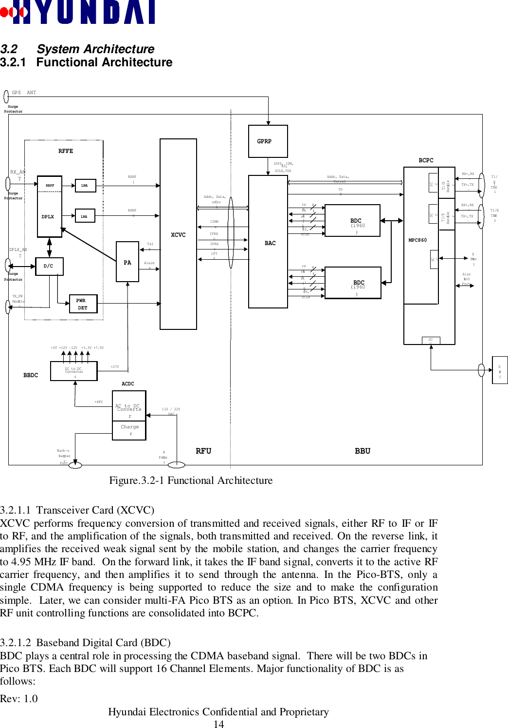
>
Hyundai Electronics Co
>
PIC800 User Manual
>
System Description
Contents
1.
System Description
2.
OperationsMANUAL
System Description
Navigation menu
Upload a User Manual
Namespaces
Wiki Guide
HTML
PDF
Info
Views
User Manual
Discussion / Help
Navigation
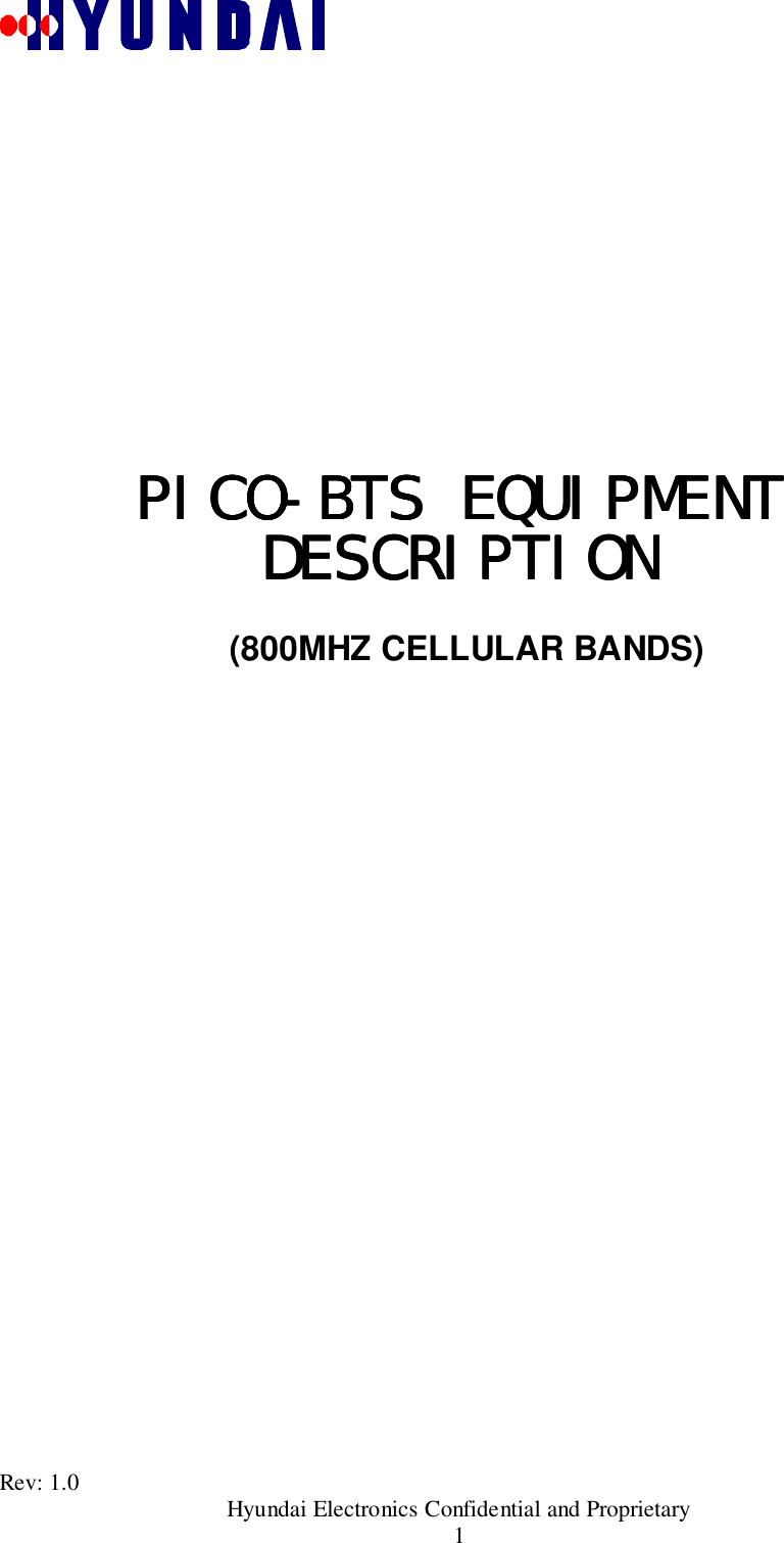
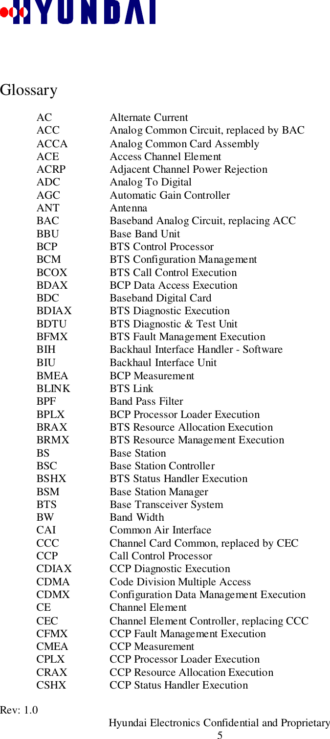
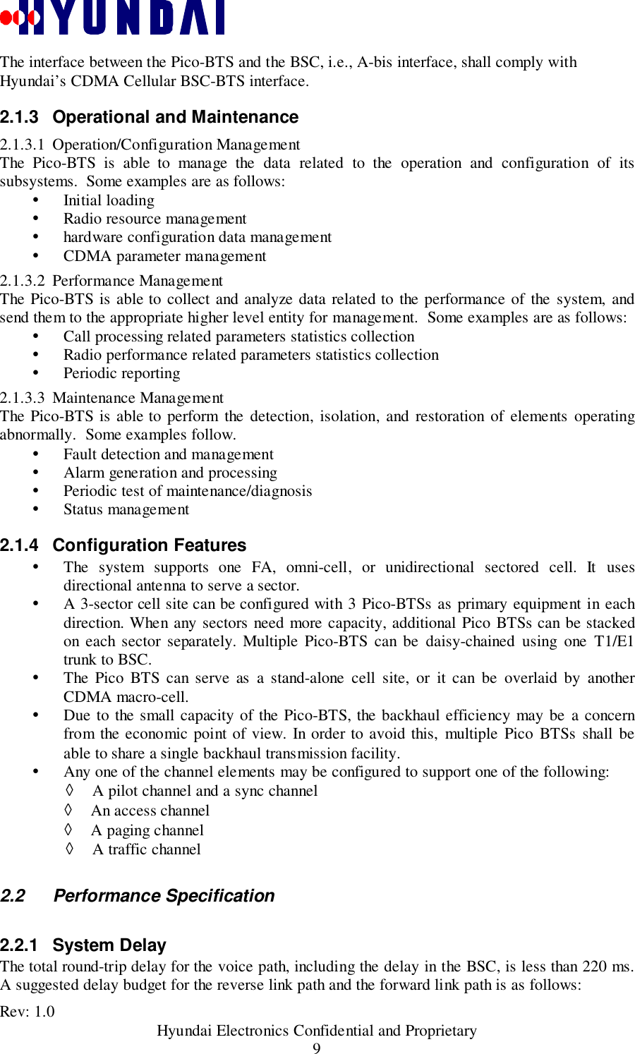
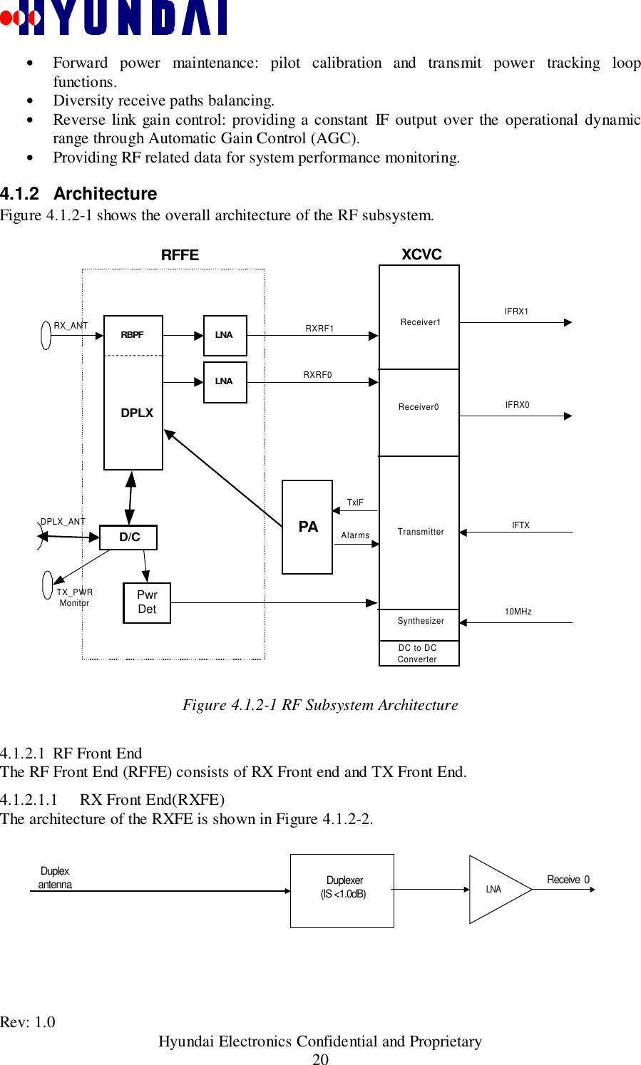
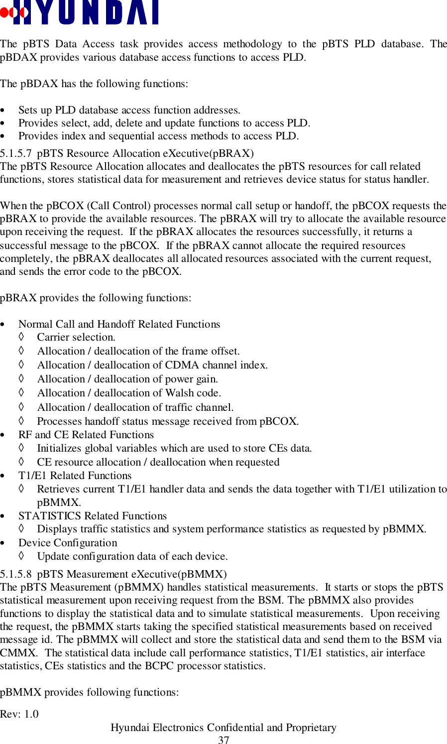
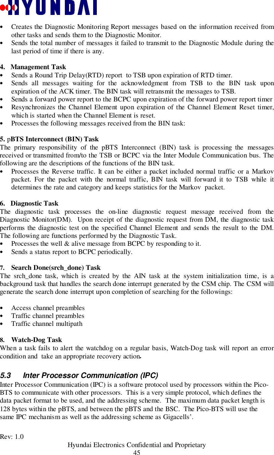
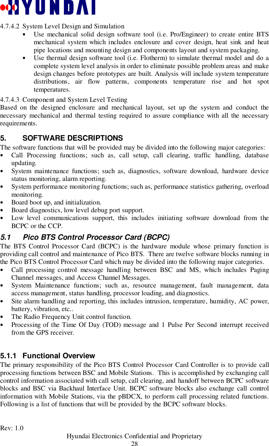
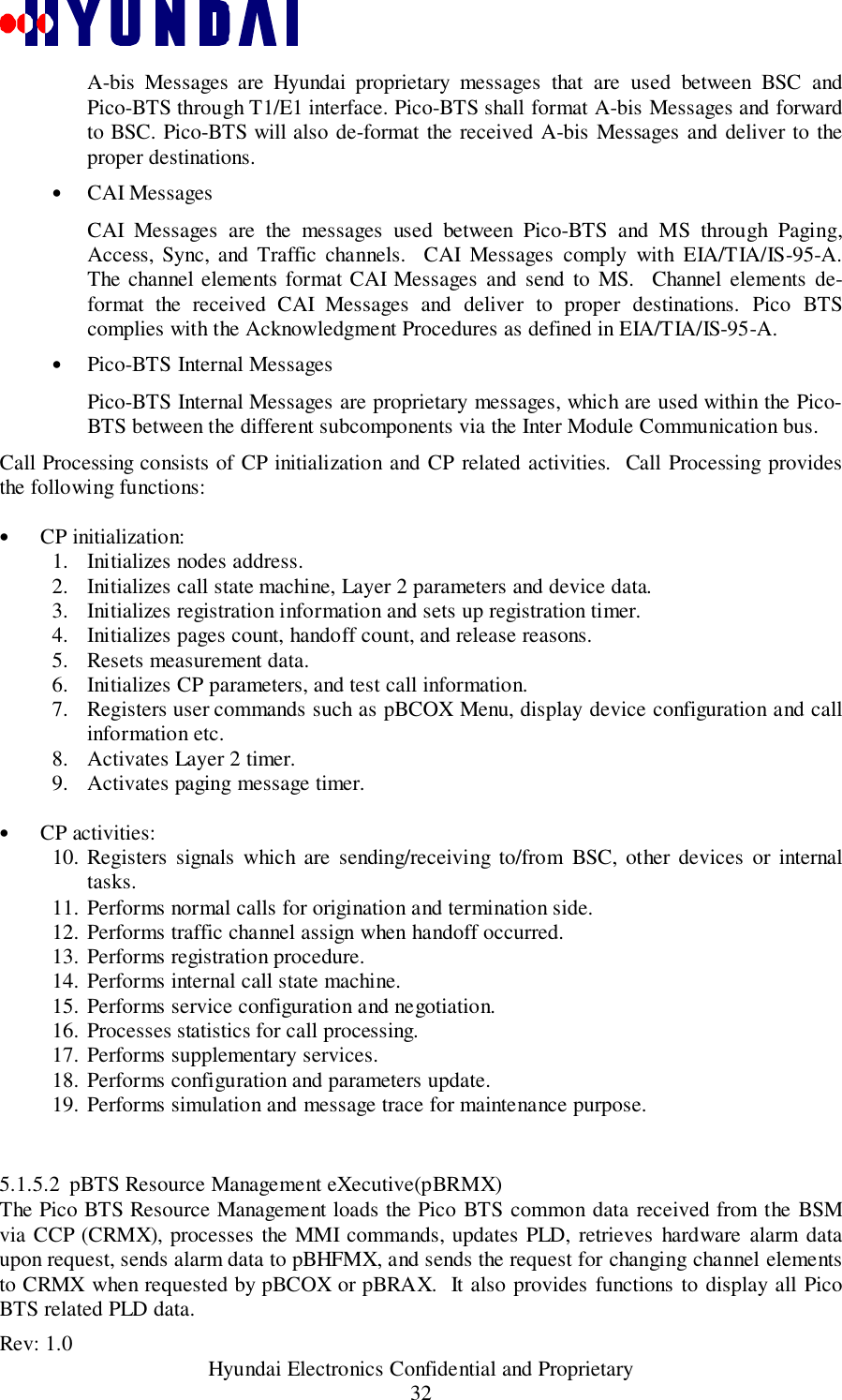
![Rev: 1.0 Hyundai Electronics Confidential and Proprietary244.2 Pico-Baseband Digital Card (BDC)4.2.1 FunctionalityFigure Figure 4.2-1 illustrates the external interface between BDCs and other boards.BAC82ESEC, SYS_CLKBRXI0[3:0]BRXQ0[3:0]8Debug Por t(RS232)GPS Antenna BDC0BDC1Debug Por t(RS232)4BTXI 0[1:0]BTXQ 0[1: 0]Int erface Signa lsInt erface Signa lsBCPController T1 Handler4GPSBCPCBRXI1[3:0]BRXQ 1[3: 0]BTXI 1[1:0 ]BTXQ 1[1: 0]BD0_ cpu_faultN,BD0_clk_faultNBD0_ cpu_faultN,BD0_clk_faultN Figure 4.2-1 Major Interfaces of BDCBDC’s major functions are as follows:1. Transmits pilot, sync, paging, and forward traffic channel messages. Receivesaccess and reverse traffic channel messages.2. Demodulates received CDMA I & Q signals from BAC.3. Modulates the incoming voice/data packets from the T1 line and serially transfers tothe BAC.4. Performs actions according to the commands of BCPC.5. Exchanges traffic and control data with BCPC through a SCC port.4.3 Pico BTS Control Processor Card (BCPC)The BCPC is the main control processor in the pBTS structure. It has a role to interface andcommunicate with other units and to process signaling messages for call management. It hasfollowing capacity and functions:• computing power: larger than 15MIPS.• Status and alarm monitoring for all units in BTS.• Storing the program and data from BSC for BCPC and BDC.In terms of hardware, BCPC provides the following functions:• Core Processing Unit,• BSC Interface,• BDC Interface,• BAC Interface,• XCVC Interface,• GPRP Interface.](https://usermanual.wiki/Hyundai-Electronics-Co/PIC800.System-Description/User-Guide-93925-Page-24.png)
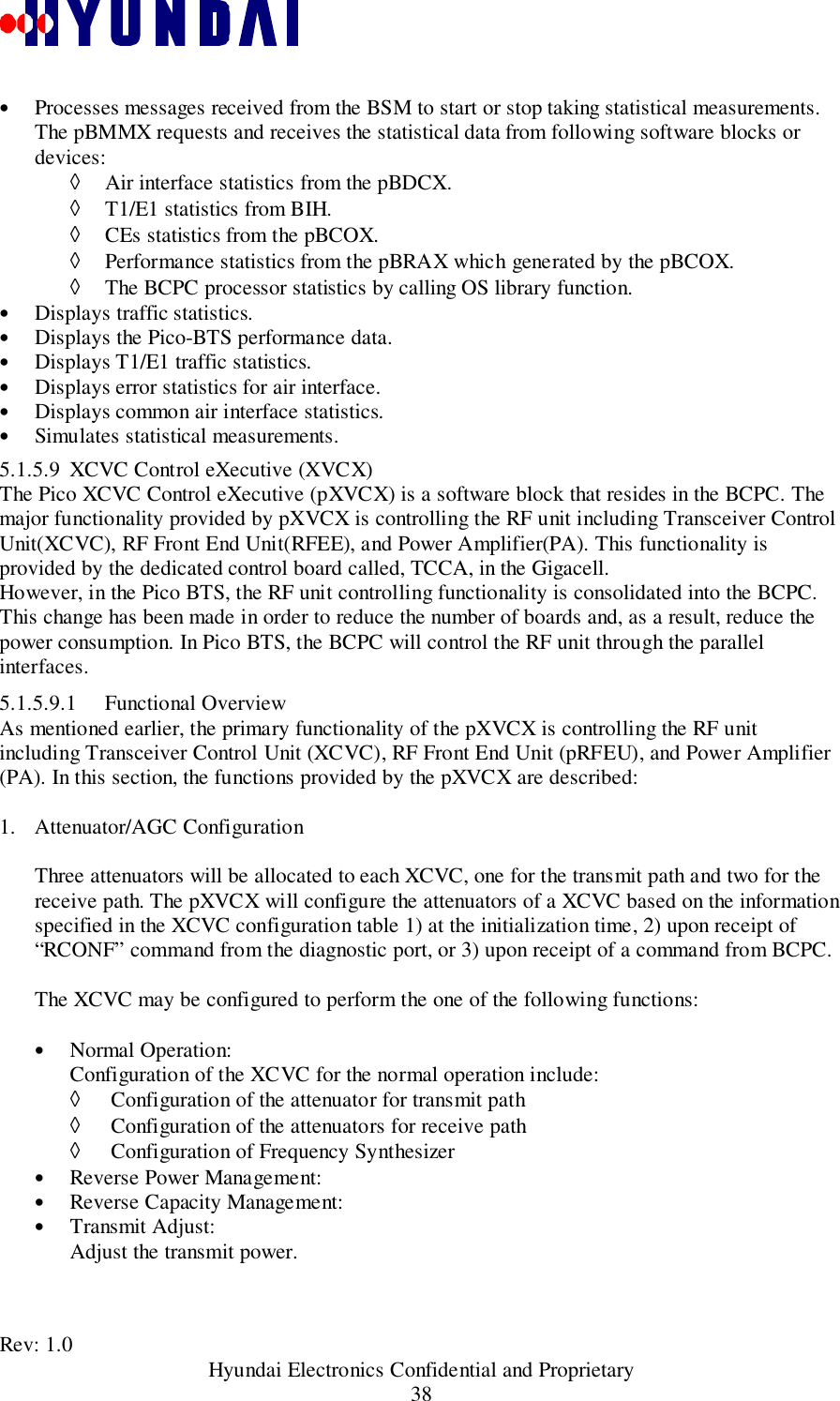
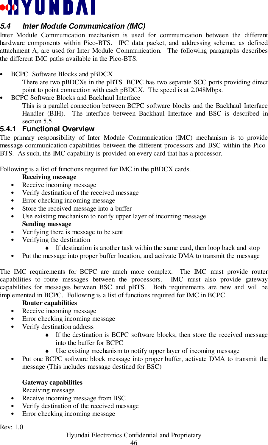
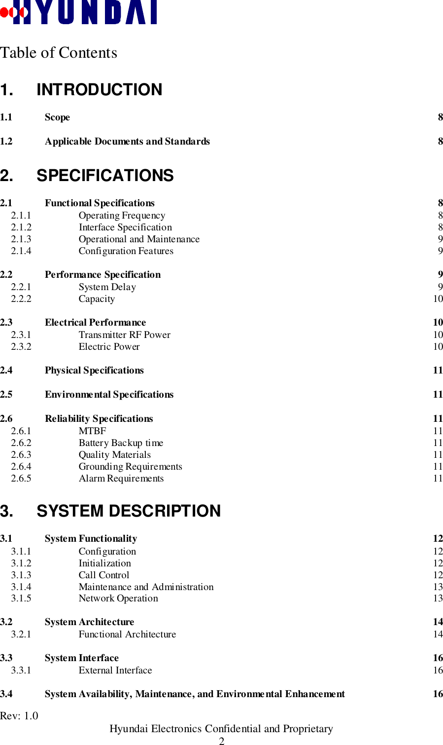
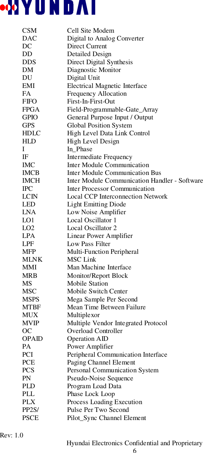
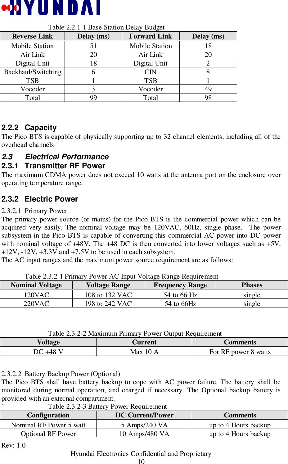
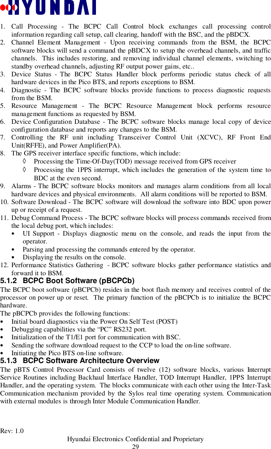
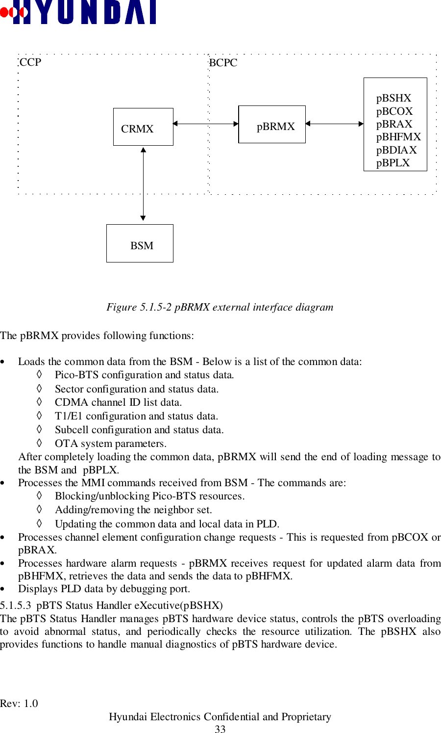
![Rev: 1.0 Hyundai Electronics Confidential and Proprietary25Figure 4.3-14.4 BTS Baseband Analog Card(BAC)BAC has following functions:• Digital summing of I & Q streams from two BDCs.• Modulating digital-to-analog converted (DAC) baseband I & Q signals with 4.95 MHz I& Q intermediate frequency(IF) carriers and sending to XCVC.• Demodulating the received 4.95Mhz IF signal from XCVC into I & Q baseband signals,analog-to-digital converting (ADC), and sending to BDCs.• Providing the XCVC interface for BCPC.• Providing GPS receiver processor (GPRP) interface for BTS and clock/frequencydistribution.BOOTFLASH128-512KBEXECFLASH-04MBEXECFLASH-14MBDRAM-04MBDRAM-14MBLocal Bus81616323232T1 FramerBT83708SCC HDLC T1 to remote BSCSCCSCC Debug PortSCC HDLC to DM portSMC UART to GPS receiverI2CTEMPSensorIDEEPROMUART16C5508EPLDEPM71288TTLIN[11:0]IRQIN[11:0]TTLOUT[23:0]ADCMAX192MPC860SPIHumiditySensorVoltages,Other monitor signalsT1 FramerBT8370HDLC T1 to other BTSBDCs8](https://usermanual.wiki/Hyundai-Electronics-Co/PIC800.System-Description/User-Guide-93925-Page-25.png)
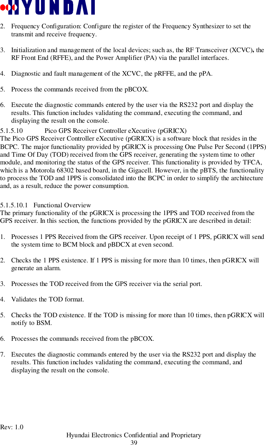
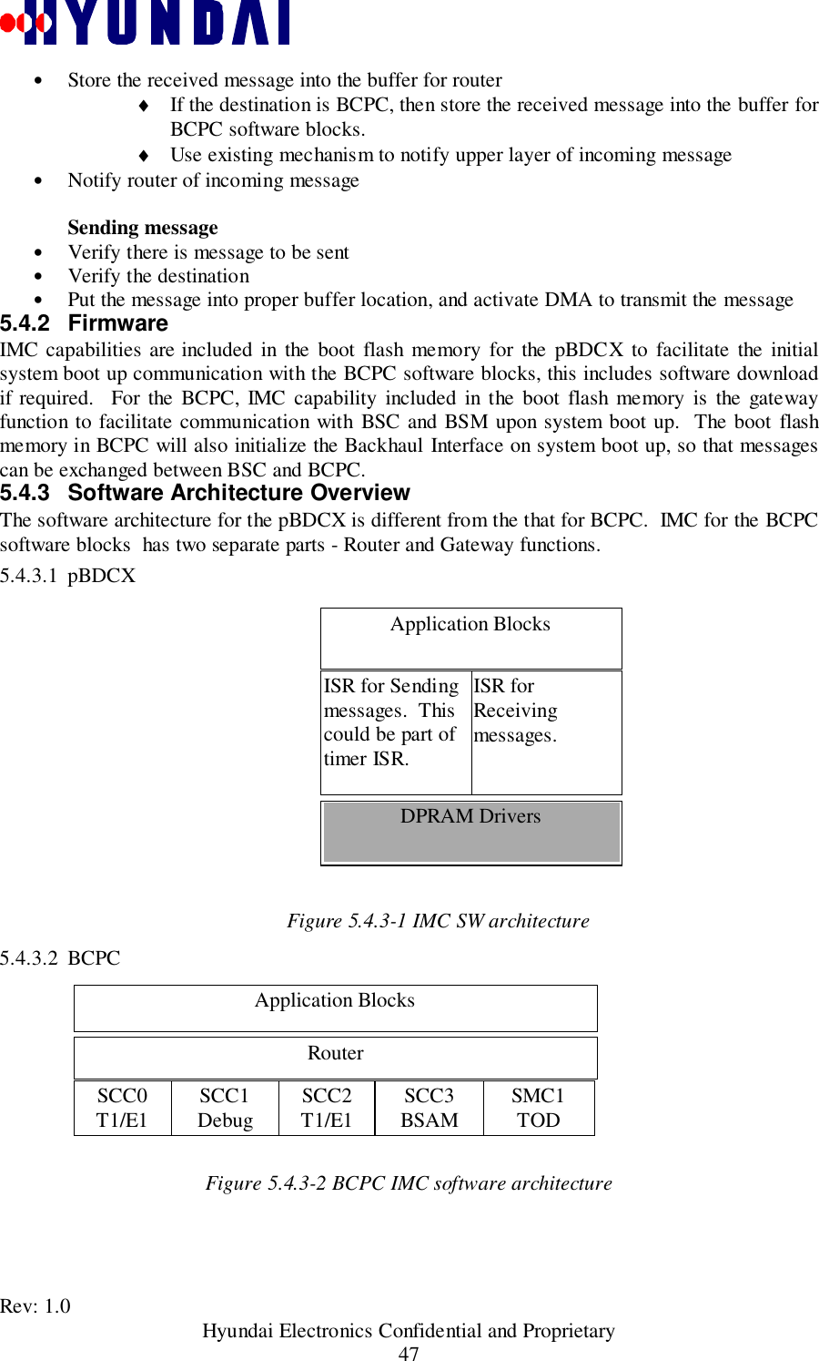
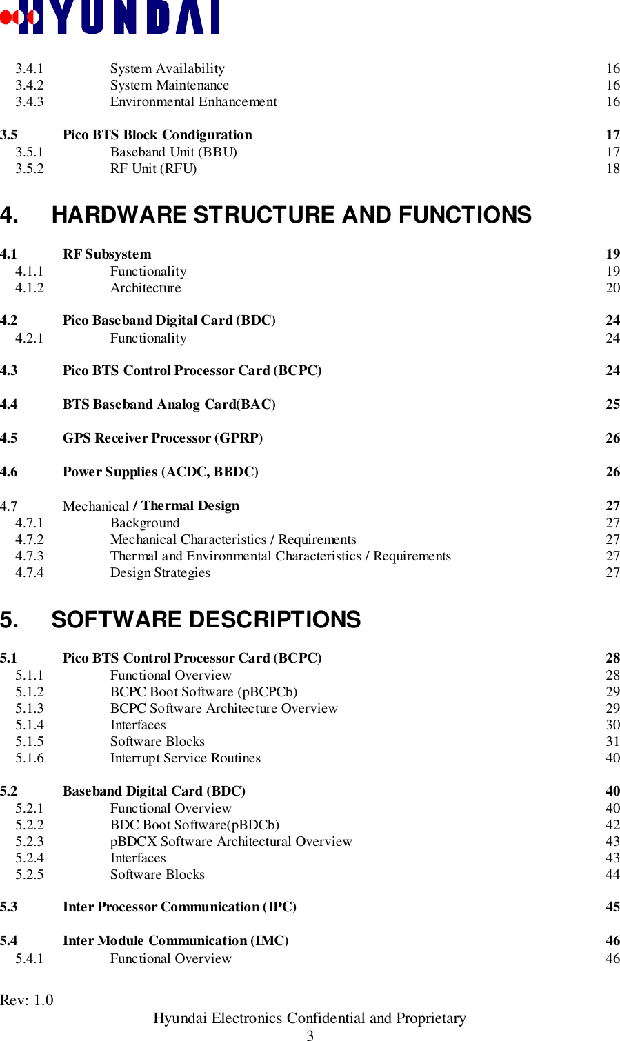
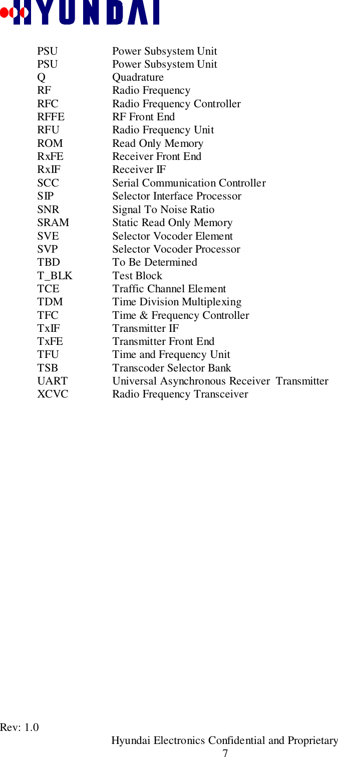
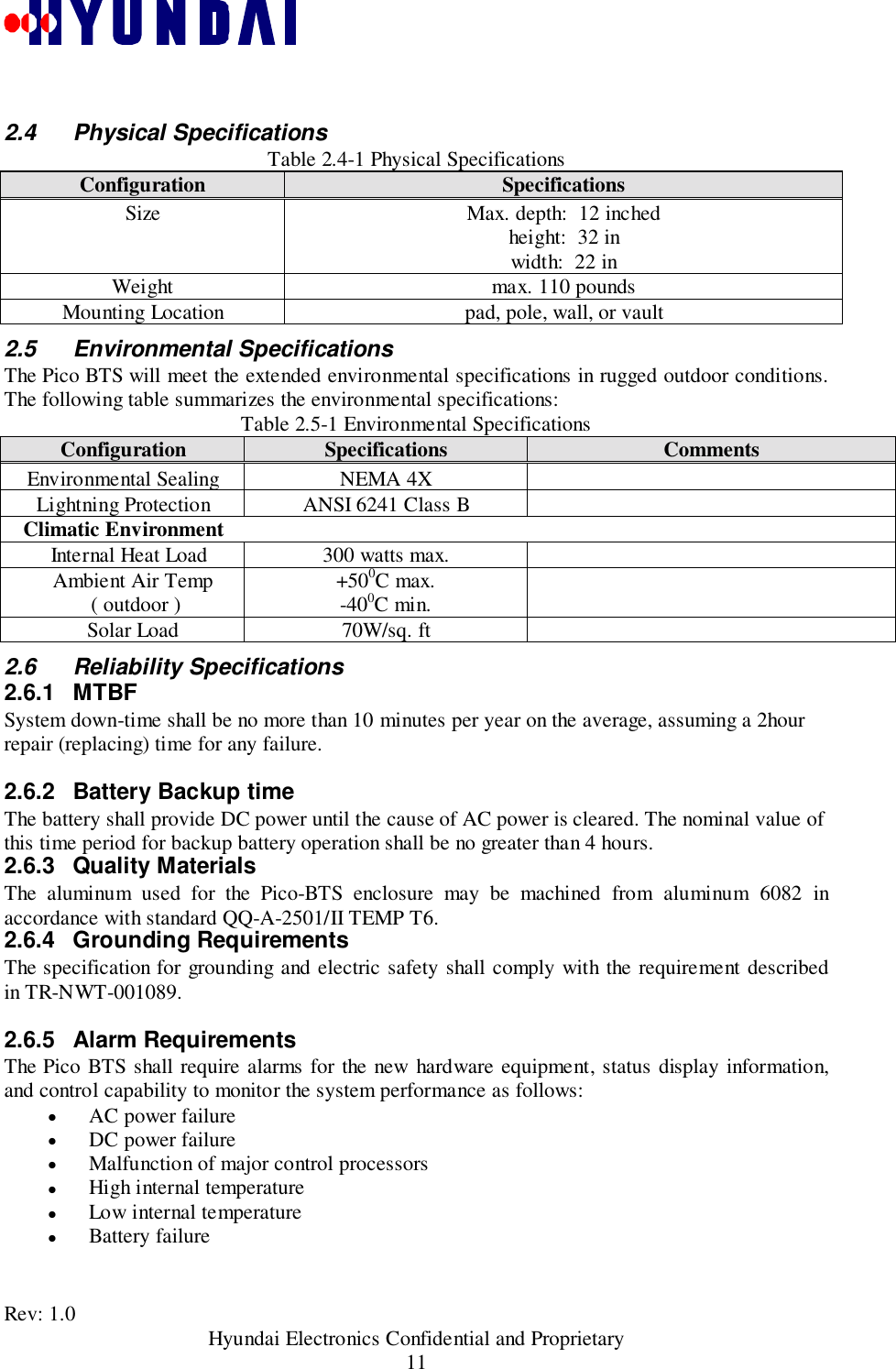
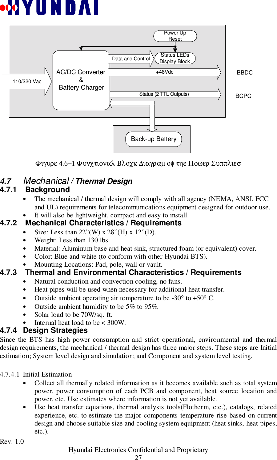
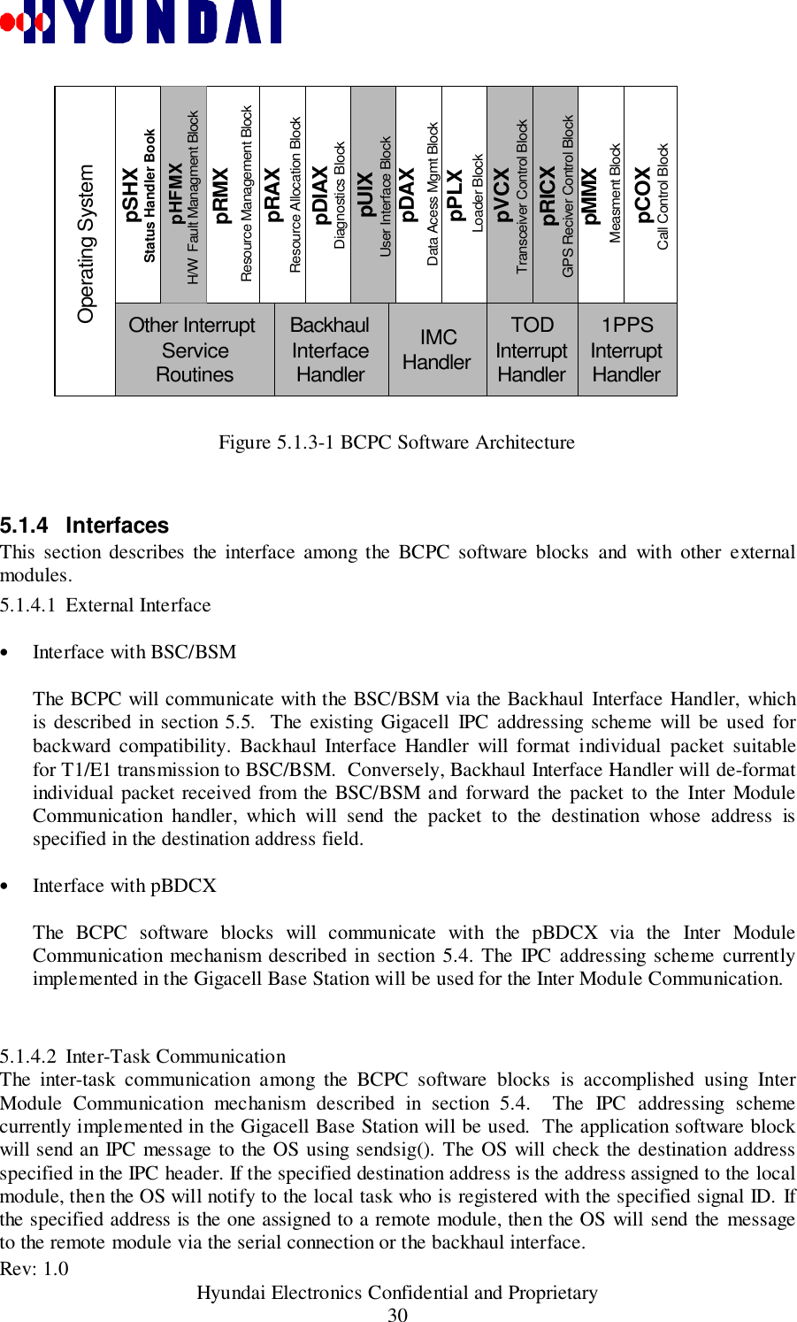
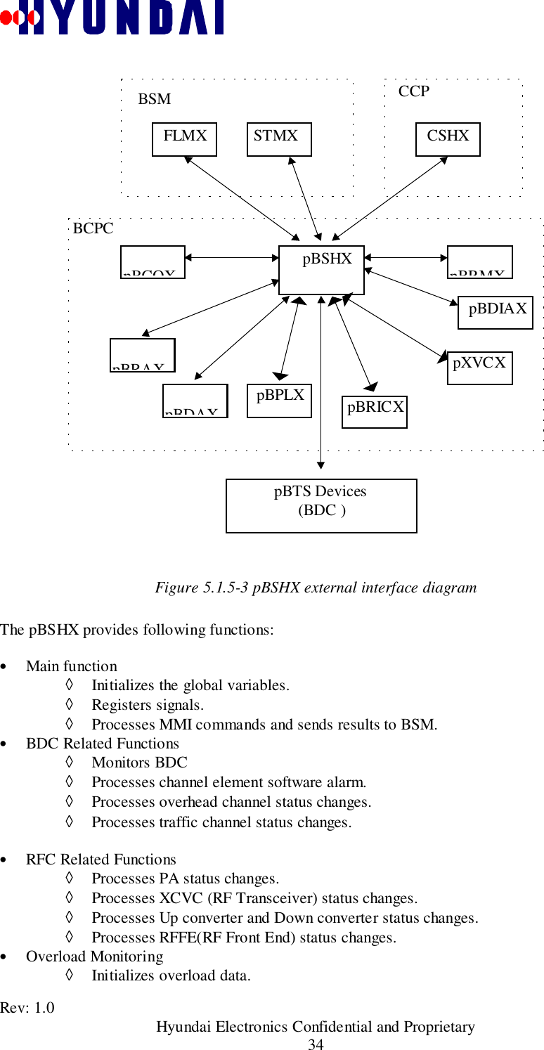
![Rev: 1.0 Hyundai Electronics Confidential and Proprietary26Figure 4.4-1 Overall Functional Block Diagram of BAC4.5 GPS Receiver Processor (GPRP)The Global Positioning System Receiver Processor (GPRP) derives accurate clock for the BTSsystem. It generates 10 MHz clock , System Clock 19.6608 MHz, 1 Pulse Per Second (1PPS) andEven Pulse Per 2 Seconds (EPP2S). Time of Day (TOD) information in ASCII code derives vianull modem serial port. The GPRP is self-sustained module that combines a GPS receiver,double-oven precise oscillator and microprocessor. The GPRP provides time outputssynchronized with the GPS time and frequency accuracy of better than 1x10-11, averaged over 24hours. When no satellites are being traced (holdover), the time output drifts less than +/- 7microseconds in 24 hours and GPRP delivers clocks with accuracy of +/-3x10-10 over a -20°C to+70° temperature range. At first startup GPSRP performs 24 hours survey to determine theantenna position and to discipline the frequency oscillator. The GPSRP provides reliablereception with the remote GPS antenna.4.6 Power Supplies (ACDC, BBDC)The ACDC converts the 110/220 (nominal) input to +48VDC. BBDC converts +48Vdc to+27Vdc, +12Vdc, +5Vdc, and +3.3Vdc. ACDC supports optional battery backup through anexternal port on the housing. Seamless power switching from AC input power to back up batterypower is achievable through the internal control circuitry which constantly monitors the DCoutput of the +48Vdc power supply and battery. If input power or power supply failureoccurred, the internal circuitry automatically controls the relay to switch from input AC power tothe back-up battery without glitch.IF-basebandmod/demodBACGPRPRXI[3:0]RXQ[3:0]ES,SCLKPERR_I/QCNTL/4TXI[1:0]TXQ[1:0]BDC0RXI[3:0]RXQ[3:0]ES,SCLKPERR_I/QCNTL/4TXI[1:0]TXQ[1:0]BDC11PPS,ESSCLK,10MHZTODDIGITAL IFES,10MHZ1PPS,TODADDR,DATA,CSn,R/W,INTRn,..ADDR,DATA,WEn,OEnAnalog monitorAnalog monitorRXIF1RXIF2TXIF10MHZGPS signal5V feedingXCVRGPSAnt.BCPC](https://usermanual.wiki/Hyundai-Electronics-Co/PIC800.System-Description/User-Guide-93925-Page-26.png)
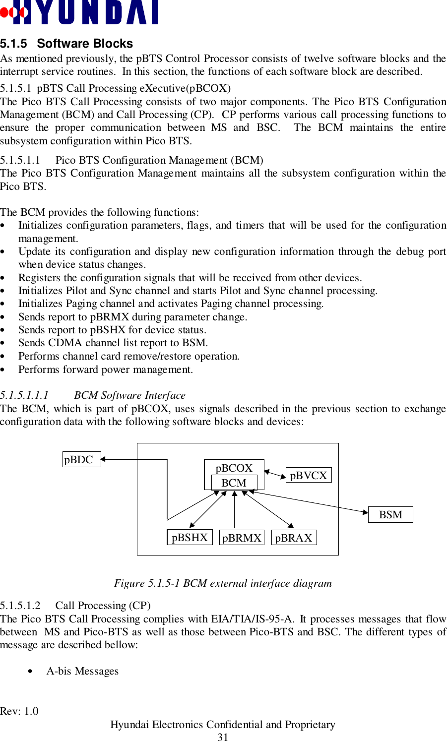
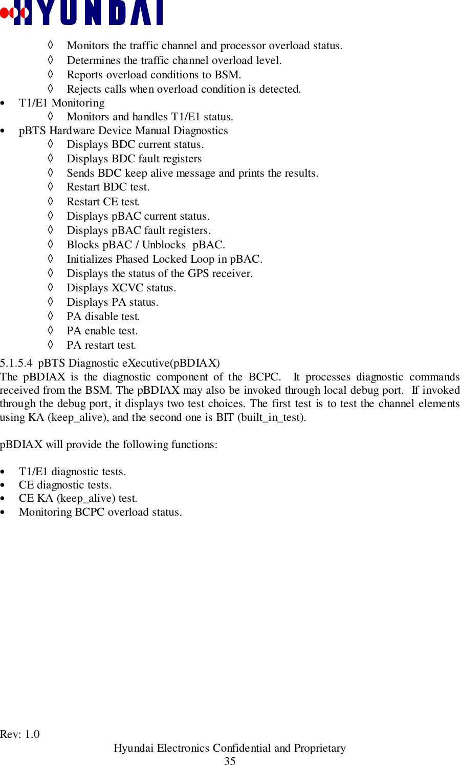
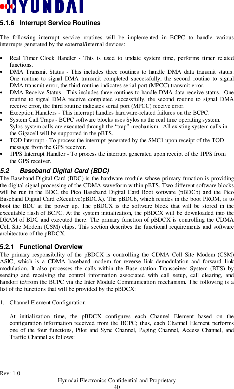
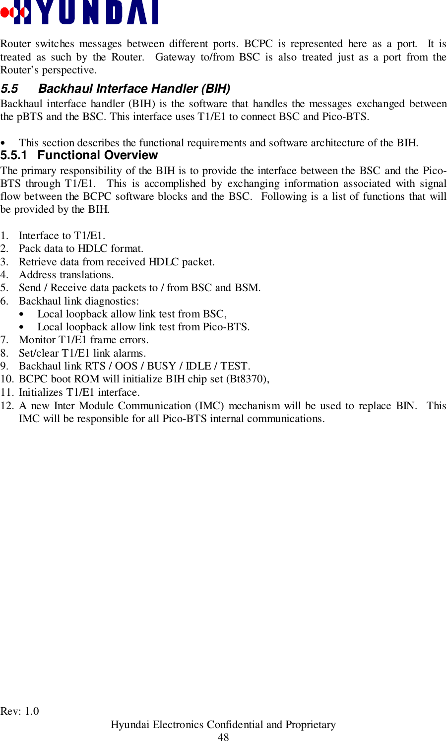
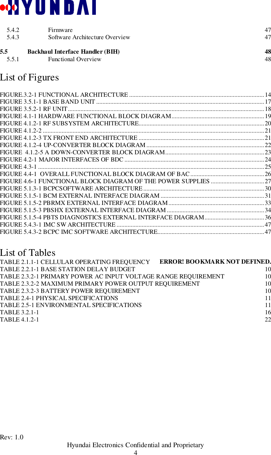
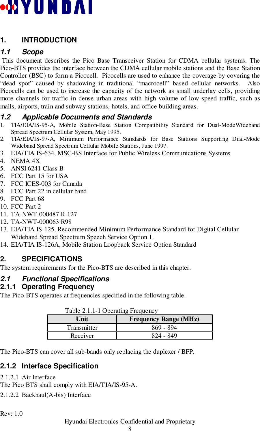
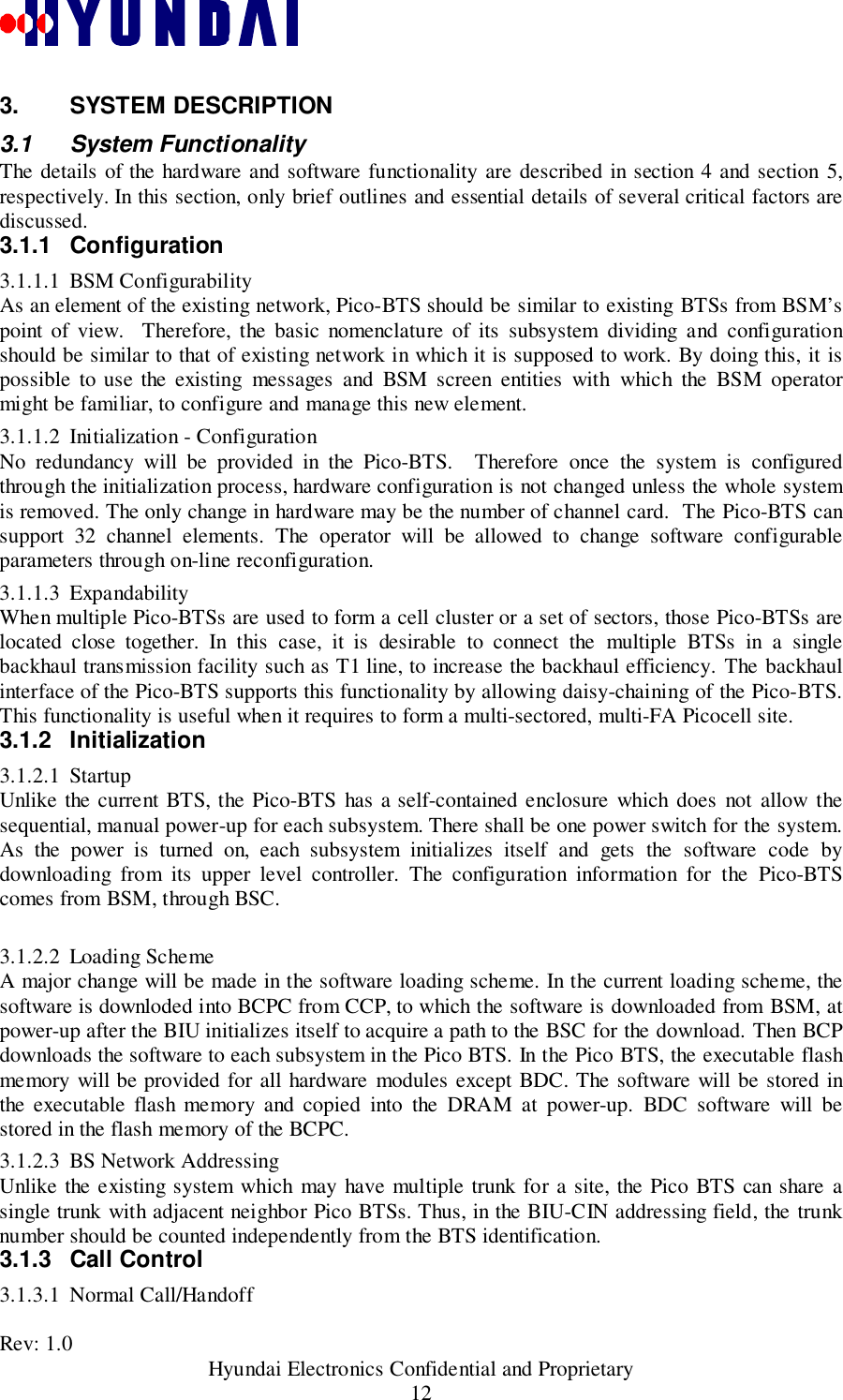
![Rev: 1.0 Hyundai Electronics Confidential and Proprietary36ACEpBDCXTCEPCEPSCEpDIAXMainT1/E1HandlerCCPΦιγυρε 5.1.5−4 πΒΤΣ ∆ιαγνοστιχσ εξτερναλ ιντερφαχε διαγραµDiagnostic requests are stored in individual arrays for each equipment type. The arrays are:• Pilot and SYNC channel element array (psce_req_table[]),• Paging channel element array (pce_req_table[]),• Access channel element array (ace_req_table[]),• Traffic channel element array (tce_req_table[]), and• Channel control array (cc_req_table[]).5.1.5.5 pBTS Processor Loader eXecutive(pBPLX)The pBTS Processor Loader handles downloading software from the CCP to the BCPC processor,and downloading software from the BCPC to the pBDCX processor.The pBPLX has the following functions:• Initializes global parameters and loading table.• Registers signals.• Loads BCPC software blocks, and pBDCX.• Updates subsystem loading status.• Performs loading error report.• Performs checksum for data/text transactions.5.1.5.6 pBTS Data Access eXecutive(pBDAX)](https://usermanual.wiki/Hyundai-Electronics-Co/PIC800.System-Description/User-Guide-93925-Page-36.png)