ICOM orporated 316700 VHF/UHF Amateur Transceiver User Manual ID 880H Draft
ICOM Incorporated VHF/UHF Amateur Transceiver ID 880H Draft
UserManual.wiki
>
ICOM orporated
>
316700 User Manual
>
User Manual 1
Contents
1.
User Manual 1
2.
User Manual 2
3.
User Manual 3
4.
User Manual 4
User Manual 1
Navigation menu
Upload a User Manual
Namespaces
Wiki Guide
HTML
PDF
Info
Views
User Manual
Discussion / Help
Navigation
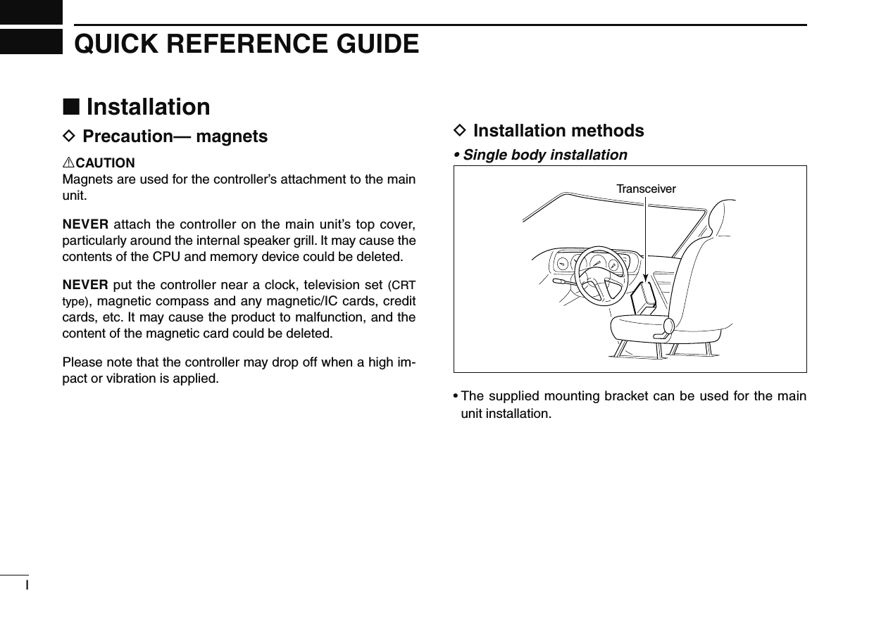
![VIIIQUICK REFERENCE GUIDE12345678910111213141516171819N Your first contactNow that you have your ID-880H installed in your car or shack, you are probably anxious to get on the air. We would like to take you through a few basic operation steps to make your first time “On The Air” an enjoyable experience. 1. Turning ON the transceiverBefore powering up your ID-880H, you may want to make sure the audio volume and squelch level controls are set in 9–10 o’clock positions.[SQL]Although you have purchased a brand new transceiver, some settings may be changed from the factory defaults because of the Quality Control (QC) process. Resetting the CPU is necessary to start from factory default.[VFO/MHz] Partial reset[S.MW]± While pushing and holding [S.MW] and [VFO/MHz] keys, push and hold [] for 1 sec. to reset the CPU.2. Selecting the operating frequency bandThe ID-880H can use 2 m or 70 cm transmittable bands.[BAND] [DIAL] Frequency band initial is displayed.± Push [BAND] then rotate [DIAL] to select the desired fre-quency band.• Push [BAND] again to return to frequency indication.Using the HM-133You can select the desired frequency band from the HM-133.PushPush• 144 MHz band• 400 MHz band](https://usermanual.wiki/ICOM-orporated/316700.User-Manual-1/User-Guide-1074900-Page-12.png)
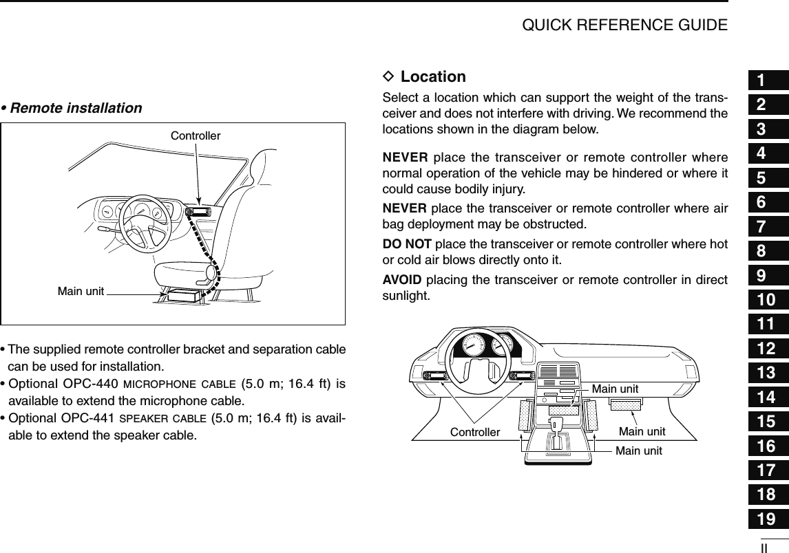
![IXQUICK REFERENCE GUIDE4. Tune the frequencyThe tuning dial will allow you to dial in the frequency you want to use. Pages 17 and 18 will instruct you on how to set the tuning speed.[DIAL]Rotate [DIAL] to tune the frequency.Using the HM-133You can directly enter the frequency with the HM-133 keypad.[EXAMPLE]: Setting frequency to 145.3625 MHz.PushPushPushPush](https://usermanual.wiki/ICOM-orporated/316700.User-Manual-1/User-Guide-1074900-Page-13.png)
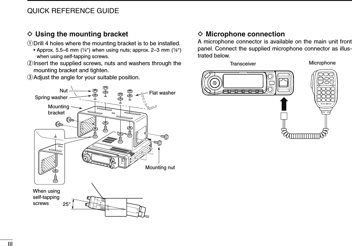
![XQUICK REFERENCE GUIDE12345678910111213141516171819N Repeater operation1. Setting duplex ± Push [BAND] then rotate [DIAL] to select the frequency band. Then rotate [DIAL] to select the repeater frequency.± Push and hold [DUP](LOW) for 1 sec. then rotate [DIAL] to select minus duplex or plus duplex.• The USA version has an auto repeater function, therefore, set-ting duplex is not required.[DUP][DIAL]2. Repeater tone Push and hold [TONE](M/CALL) for 1 sec. then rotate [DIAL] to select “TONE,” if the repeater requires a subaudible tone to be accessed.[TONE][DIAL]Using the HM-133Plus or minus duplex selection and the repeater tone setting can be made easily via the HM-133.Push [DUP– 7(TONE)] for minus duplex; [DUP+ 8(TSQLS)] for plus duplex selection, push [FUNC] then [DUP– 7(TONE)] to turn the repeater tone ON.PushPush , then Push](https://usermanual.wiki/ICOM-orporated/316700.User-Manual-1/User-Guide-1074900-Page-14.png)
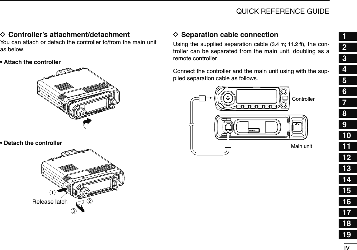
![XIQUICK REFERENCE GUIDEThe ID-880H has a total of 1052 memory channels (including 25 pairs scan edges and 2 call channels) for storing often used operating frequency, repeater settings, etc.1. Setting a frequencyIn VFO mode, set the desired operating frequency with re-peater, tone and tuning steps, etc. ± Push [VFO/MHz] to select VFO.± Rotate [DIAL] to set the desired frequency. • Set other data, such as repeater tone, duplex information, tuning step), if desired.2. Selecting a memory channel Push [S.MW], then rotate [DIAL] to select the desired mem-ory channel.• “X” indicator and memory channel number blink.[S.MW ]3. Writing a memory channelPush and hold [MW](S.MW) for 1 sec. to program.• 3 beeps sound• Return to VFO mode automatically after programming.• Memory channel number automatically increases when continuing to push [MW](S.MW) after programming.Using the HM-133q Push [MR/CALL] to select memory mode.w Push [ENT C(T-OFF)] first, then enter the desired memory channel via the keypad.e Push [VFO/LOCK] to select VFO mode, then set the de-sired operating frequency, including offset direction, tone settings, etc. ± Push [VFO/LOCK] to select VFO. ± Push [ENT C(T-OFF)] first, then enter the desired operat-ing frequency via the keypad. • Set other data, such as repeater tone, duplex information, tuning step, if necessary.r Push [FUNC] then push and hold [CLR A(MW)] for 1 sec. to program.Push , then • 3 beeps sound • Memory channel number automatically increases when continu-ing to push [CLR A(MW)] after programming.N Programming memory channels](https://usermanual.wiki/ICOM-orporated/316700.User-Manual-1/User-Guide-1074900-Page-15.png)
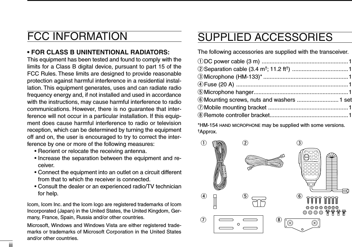
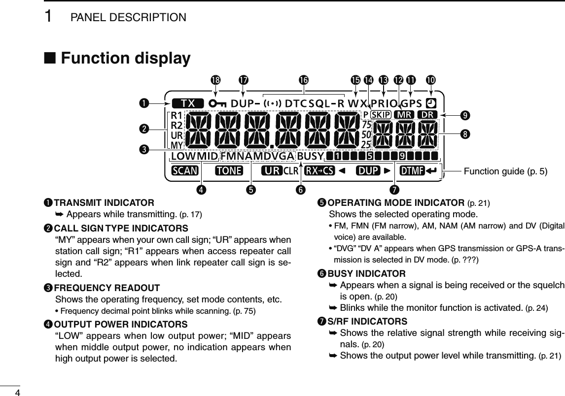
![11PANEL DESCRIPTION12345678910111213141516171819N Main unitq e r twyRear viewq ANTENNA CONNECTOR [ANT] (p. IX)Connects a 50 Ω antenna with a PL-259 connector and a 50 Ω coaxial cable for transmission and reception.w COOLING FAN Rotates while transmitting. Also rotates while receiving depending on the setting in FUNC set mode (SET). (p. 101)e DATA JACK [DATA] (p. 57)± Connect a PC through the optional data communication cable OPC-1529R, for low-speed data communication in DV mode or data cloning with the cloning software CS-80/880 (free download).± Connect a GPS receiver through the optional data com-munication cable OPC-1529R, for GPS operation.r PACKET JACK [PACKET] (pgs. 120, 121) Connects a TNC (Terminal Node Controller), etc. for data communications. The receiver can support 1200/9600 bps packet communication (AFSK/GMSK).t EXTERNAL SPEAKER JACK [SP]± Connects an 8 Ω speaker.• Audio output power is more than 2.0 W.± Connect an optional cloning cable OPC-478UC or OPC-474 for data cloning.y POWER RECEPTACLE [DC13.8V] Accepts 13.8 V DC ±15% with the supplied DC power cable. NOTE: DO NOT use a cigarette lighter socket as a power source when operating in a vehicle. The plug may cause voltage drops and ignition noise may be su-perimposed onto transmit or receive audio.ANTENNA INFORMATIONFor radio communications, the antenna is of critical impor-tance, to maximize your output power and receiver sensitiv-ity. The transceiver accepts a 50 Ω antenna and a Voltage Standing Wave Ratio (VSWR) of 1.5:1 or less. High SWR values not only may damage the transceiver but also lead to TVI or BCI problems.](https://usermanual.wiki/ICOM-orporated/316700.User-Manual-1/User-Guide-1074900-Page-16.png)
![22BASIC OPERATIONq MENU•LOCK KEY [MENU ]± Push to enter menu screen indication ON and OFF. (p. 7)± Push and hold for 1 sec. to toggle the lock function ON and OFF. (p. 19)w SELECT MEMORY WRITE•MEMORY WRITE KEY [S.MW•MW]± Push to enter select memory write mode for memory channel programming. (pgs. 62, 73, 76)• Push [MENU ] to cancel and exit the select memory write mode.± Push and hold to store the frequency, operating mode, etc. into the selected memory channel. (pgs. 62, 73, 76)e TUNING DIAL [DIAL]Selects the operating frequency (p. 17), memory channel (p. 61), the setting of the set mode item and the scanning direction (p. 75).r BAND•MODE KEY [BAND•MODE]± Push to enter band selection state. (p. 15)• Rotating [DIAL] selects the band.± Push and hold for 1 sec. to enter operating mode selec-tion state. (p. 15)• Rotating [DIAL] selects the operating mode.t VFO/MHz TUNING•SCAN KEY [VFO/MHz•SCAN]± Push to select VFO mode. (p. 17)± During VFO mode operation, push to select 1 MHz and 10 MHz tuning steps. (p. 75)± Push and hold for 1 sec. to enter scan type selection state. (p. 75)• Cancels a scan when pushed during scan.y MEMORY/CALL•TONE KEY [M/CALL•TONE]± Push to select memory, call and weather channel* modes. (pgs. 61, 72, 123)*Weather channels are available for USA version only.N Front panel— controllerVFO/MHzBANDMODEVOLSQLM/CALL CSDR LOWMONIS.MWMWMENUuytr!0oiFunction display (p. 3)wqe!4!3!2!1](https://usermanual.wiki/ICOM-orporated/316700.User-Manual-1/User-Guide-1074900-Page-17.png)
![32BASIC OPERATION12345678910111213141516171819± During FM/FM-N mode operation, push and hold for 1 sec. to enter tone function selection state. (pgs. 86, 91)• Rotating [DIAL] selects the tone function.• T (Repeater tone), TSQL , TSQL, DTCS , DTCS, tone squelch reverse, DTCS squelch reverse or tone function OFF can be selected.± During DV mode operation, push and hold for 1 sec. to select digital call sign squelch, digital code squelch and no squelch operation in sequence. (p. 149)• DSQL , DSQL, CSQL , CSQL or digital call squelch OFF can be selected.u D-STAR REPEATER•YOUR KEY [DR•UR]± Push to select DR mode. (p. 21)• Rotating [DIAL] selects access repeater.• DV mode is automatically selected.± During DV mode operation, push and hold for 1 sec. to enter your call sign selection state. (p. 30)• Rotating [DIAL] selects your call sign.• DV mode is automatically selected.i CALL SIGN•RX CALL WRITE KEY [CS•RXCS]± Push to display the current call sign. (p. 21)• Rotating [DIAL] selects UR (your) call sign, R1 (access re-peater) call sign, R2 (link repeater) call sign and MY (your own) call sign.± Push and hold for 1 sec. to set the received call signs (stations and repeaters) to current call sign. (p. 30)o OUTPUT POWER•DUPLEX KEY [LOW•DUP]± Each push changes the output power selection. (p. 21)• LOW, MID and HIGH (no indicator visible) are available.± Push and hold for 1 sec. to enter duplex operation se-lection state. (p. 30)• Rotating [DIAL] selects the tone function.• DUP– (minus duplex), DUP (plus duplex) and simplex (no indicator visible) are available.!0 MONITOR•DTMF KEY [MONI•DTMF]± Push to turn the monitor function ON and OFF. (p. 24)± Push and hold for 1 sec. to enter DTMF set mode. (p. 82)!1 SQUELCH CONTROL [SQL]Varies the squelch level for left and right band. (p. 20)• The RF attenuator activates and increases the attenuation when rotated clockwise at and beyond the center position. (p. 22)!2 POWER KEY [PWR]Push and hold for 1 sec. to turn power ON and OFF.!3 MICROPHONE CONNECTOR (p. IV)Connects the supplied or an optional microphone. :2 q +8 V DC output (Max. 10 mA) w Channel up/down e 8 V control IN r PTT t GND (microphone ground) y MIC (microphone input) u GND i Data IN!4 VOLUME CONTROL [VOL] (p. 20)Adjusts the audio level for left or right band.](https://usermanual.wiki/ICOM-orporated/316700.User-Manual-1/User-Guide-1074900-Page-18.png)
 (p. 39)± During programming state for call signs, repeater list, memory name, etc., push to erase the selected char-acter.± During programming state for call signs, repeater list, memory name, etc., push and hold for 1 sec. to erase all character following the corsor.w LEFT KEY [](CS)± During programming state for call signs, repeater list, memory name, etc., push to move the cursor left. ± During menu screen operation, push to select the upper layer. (p. 113)e RIGHT KEY [](LOW)± During programming state for call signs, repeater list, memory name, etc., push to move the cursor right. ± During menu screen operation, push to select the lower layer. (p. 113)r ENTER KEY [ ](MONI) (p. 48)± During menu screen operation, push to enter or exit to/from the selected set items, etc. (p. 113)± During programming state for call signs, repeater list, etc., push to set or store the setting.](https://usermanual.wiki/ICOM-orporated/316700.User-Manual-1/User-Guide-1074900-Page-21.png)
![71PANEL DESCRIPTION12345678910111213141516171819N Microphone (HM-133*)Mic elementqertwyuio!0!1q VFO/LOCK KEY [VFO/LOCK]± Push to select VFO mode. (p. 16)± Push and hold for 1 sec. to turn the lock function ON and OFF. (p. 19)w PTT SWITCH± Push and hold to transmit; release to receive.± Switches between transmitting and receiving while the one-touch PTT function is in use. (p. 26)e UP/DOWN KEYS [Y]/[Z]± Push either key to change operating frequency, memory channel, set mode setting, etc. (pgs. 17, 61, 98)± Push and hold either key for 1 sec. to start scanning. (p. 75)r ACTIVITY INDICATOR± Lights red while any key, except [FUNC] and [DTMF-S], is pushed, or while transmitting.± Lights green while the one-touch PTT function is in use.t KEYPAD (pgs. 12, 13)y FUNCTION INDICATOR± Lights orange while [FUNC] is activated—indicates the secondary function of keys can be accessed.± Lights green when [DTMF-S] is activated—DTMF sig-nals can be transmitted with the keypad.u 2nd FUNCTION KEY [FUNC] i DTMF SELECT KEY [DTMF-S] (p. 84)o FUNCTION KEYS [F-1]/[F-2] (p. 115)Program and recall your desired transceiver configuration.!0 BAND KEY [BAND] (p. 15)Push to select main band between left and right bands. !1 MEMORY/CALL KEY [MR/CALL]± Push to select memory mode. (p. 61)± Push and hold for 1 sec. to select call channel. (p. 72)](https://usermanual.wiki/ICOM-orporated/316700.User-Manual-1/User-Guide-1074900-Page-22.png)
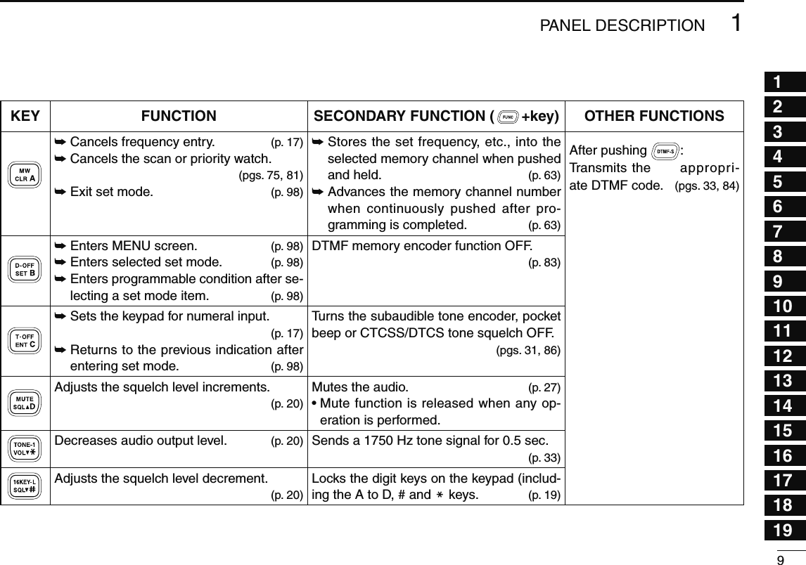
![81PANEL DESCRIPTIONN Microphone keypad KEY FUNCTION SECONDARY FUNCTION ( +key) OTHER FUNCTIONSSwitches between opening and closing the squelch. (p. 24)Starts and stops scanning. (p. 75)Starts and stops priority watch. (p. 81)Selects high output power. (p. 21)Selects mid. output power. (p. 21)Selects low output power. (p. 21)Selects minus duplex operation. (p. 31)Selects plus duplex operation. (p. 31)Selects simplex operation. (p. 31)Increases audio output level. (p. 20)In VFO mode enters operating band selec-tion.In memory mode enters bank selection. (p. 64)Starts and stops tone scanning. (p. 90)Turns the one-touch PTT function ON and OFF. (p. 26)Turns the DTCS squelch ON. (p. 86)Turns the DTCS pocket beep function ON. (p. 86)Turns the DTMF memory encoder function ON. (p. 83)Turns the subaudible tone encoder ON. (p. 31)Turns the CTCSS pocket beep function ON. (p. 86)Turns the tone squelch function ON. (p. 86)Sends a 1750 Hz tone signal while pushing and holding. (p. 33)After pushing :Transmits the appropri-ate DTMF code. (pgs. 33, 84)When the DTMF memory en-coder is activated, push [0] to [9] to transmit the appropriate DTMF memory contents . (p. 84)](https://usermanual.wiki/ICOM-orporated/316700.User-Manual-1/User-Guide-1074900-Page-23.png)
![101PANEL DESCRIPTIONN Optional Microphone (HM-154)4/ONOFF)q PTT SWITCHPush and hold to transmit; release to receive.w UP/DOWN KEYS [UP]/[DN]± Push either key to change operating frequency, memory channel, set mode setting, etc. (pgs. 17, 61, 98)± Push and hold either key for 1 sec. to start scanning. (p. 75)e UP/DN LOCK SWITCHSlide to toggle [UP]/[DN] keys function ON and OFF.](https://usermanual.wiki/ICOM-orporated/316700.User-Manual-1/User-Guide-1074900-Page-25.png)
![112BASIC OPERATION12345678910111213141516171819N PreparationD Turning power ON/OFF± Push and hold [ ] for 1 sec. to turn power ON and OFF.D Operating frequency band selectionThe ID-880H has 2 m and 70 cm bands for transmission and reception. In addition, extra frequency bands 127, 220, 350, 500 and 900 MHz band are available for wide-band receiver capability (depending on versions, see p. ?? for details).[BAND] [DIAL] Frequency band initial is displayed.q Push [BAND] and rotate [DIAL] to select the desired fre-quency band. • Pushing [Y]/[Z] on the microphone also selects the band.w Push [BAND] to return to frequency indication in the se-lected frequency band.BANDY/Zz Push [BAND] to enter frequency band selec-tion. • The frequency band is displayed.x Push [Y]/[Z] to select the desired frequency band.c Push [CLR A(MW)] (or [BAND]) to exit the condi-tion, and return to frequency indication.Note that in this manual, sections beginning with a micro-phone icon (as at left), designate operation via the HM-133 microphone.](https://usermanual.wiki/ICOM-orporated/316700.User-Manual-1/User-Guide-1074900-Page-26.png)
![122BASIC OPERATIOND VFO modeVFO mode is used to set the desired frequency.± Push [VFO/MHz] to select VFO mode. • When VFO mode is already selected, the digits to the right of the 10 MHz or 1 MHz digits will disappear depending on version. In this case, push [VFO/MHz] again (or twice depending on ver-sion).[VFO/MHz]• VFO mode indicationVFO/LOCK± Push [VFO/LOCK] to select VFO mode.What is VFO?VFO is an abbreviation of Variable Frequency Oscillator. Fre-quencies for both transmitting and receiving are generated and controlled by the VFO.D Memory modeMemory mode is used for operation on memory channels which store programmed frequencies.q Push [M/CALL] to select memory mode.• Push [M/CALL] several times to select Memory/Call/Weather* channels in sequence. * Weather channels are available for the U.S.A. version only.• “X” indicator appears when memory mode is selected.Appears[M/CALL]• Memory mode indicationw Rotate [DIAL] to select the desired memory channel.• Only programmed memory channels can be selected.• See p. 92 for memory programming details.MR/CALLY/Zz Push [MR/CALL] to select memory mode.x Push [] or [] to select the desired mem-ory channel.](https://usermanual.wiki/ICOM-orporated/316700.User-Manual-1/User-Guide-1074900-Page-27.png)
![132BASIC OPERATION12345678910111213141516171819D Call/Weather* channelsCall channels are used for quick recall of most-often used frequencies. *Weather channels are available for the U.S.A. version only.q Push [M/CALL] several times to select call channels/Weather channels.• Memory/Call/Weather channels can be selected in sequence.• “C0” or “C1” appears when call channel is selected.w Rotate [DIAL] to select the desired channel.[M/CALL]• Call channel indication• Weather channel indicationMR/CALLY/Zz Push and hold [MR/CALL] for 1 sec. to se-lect call channels.• Whether channels cannot be selected by the HM-133.x Push [] or [] to select the desired call channel.D DR (D-STAR Repeater) modeDR (D-STAR Repeater) mode is used for the D-STAR re-peater operation. In this mode, you can select the pre-pro-grammed repeaters and UR (your) call sign easily.q Push [DR] to select DR mode.• “ ” appears when call channel is selected.[DR]• DR mode indicationAppearw Rotate [DIAL] to select the desired access repeater.• While rotating [DIAL], S/RF-meter indicates group number.• Only programmed access repeaters in RPT-L menu can be se-lected. See p. 40 for RPT-L (repeter lists) programming details.MENU ¶RPT-L ¶ADD-L (p. 40)](https://usermanual.wiki/ICOM-orporated/316700.User-Manual-1/User-Guide-1074900-Page-28.png)
![142BASIC OPERATIONN Using the tuning dialq Rotate [DIAL] to set the frequency.• If VFO mode is not selected, push [VFO/MHz] to select VFO mode.• The frequency changes in the selected tuning steps. (p. 18)[DIAL] [VFO/MHz]While 1 MHz tuning step is selected, the digit below 100kHz disappear.While 10 MHz tuning step is selected, the digit below 1 MHz disappear.w To change the frequency in 1 MHz (10 MHz for some versions) steps, push [VFO/MHz], then rotate [DIAL].• Pushing and holding [VFO/MHz] for 1 sec. starts scan function. If scan starts, push [VFO/MHz] again to cancel it.N Using the [Y]/[Z] keysYZ± Push [Y] or [Z] to select the desired frequency. • Pushing and holding [Y]/[Z] for 1 sec. activates a scan. If scan starts, push [Y]/[Z] or [CLR A(MW)] to cancel it.](https://usermanual.wiki/ICOM-orporated/316700.User-Manual-1/User-Guide-1074900-Page-29.png)
![152BASIC OPERATION12345678910111213141516171819N Using the keypadThe frequency can be directly set via numeral keys on the microphone.ENTCz Push [BAND] to select the desired band (left or right) as the main band.• Push [VFO/LOCK] to select VFO mode, if necessary.x Push [ENT C(T-OFF)] to activate the keypad for digit input.c Push 6 keys to input a frequency.• When a digit is mistakenly input, push [ENT C(T-OFF)] to clear the input, then repeat input from the 1st digit.• Pushing [CLR A(MW)] clears input digits and retrieves the frequency.PushPushPushPush[EXAMPLE]: Setting frequency to 145.3625 MHz.N Tuning step selectionTuning steps are the minimum frequency change increments when you rotate [DIAL] or push [Y]/[Z] on the microphone. Independent tuning steps for the left and right bands, as well as each frequency band can be set for individual tuning con-venience. The following tuning steps are available. • 5 kHz* • 6.25 kHz* • 10 kHz • 12.5 kHz • 15 kHz* • 20 kHz • 25 kHz • 30 kHz • 50 kHz • 100 kHz • 125 kHz • 200 kHz*Not selectable in 900 MHz band. NOTE: For convenience, select a tuning step that matches the frequency intervals of repeaters in your area.q Enter “TS” in MENU screen.MENU ¶ TS (p. 63) (Push [MENU ]), (Rotate [DIAL], then push [ ](MONI).)• Push [VFO/MHz] to select VFO mode, if necessary.[DIAL][MENU ][ ]w Rotate [DIAL] to select the desired tuning step.e Push [MENU ] to exit the set mode.](https://usermanual.wiki/ICOM-orporated/316700.User-Manual-1/User-Guide-1074900-Page-30.png)
![162BASIC OPERATIONN Lock functionsTo prevent accidental frequency changes and unnecessary function access, use the lock function. The transceiver has 2 different lock functions.D Frequency lockThis function locks [DIAL] and keys electronically and can be used together with the microphone lock function.[MENU ] Appears± Push and hold [MENU ] for 1 sec. to turn the lock func-tion ON and OFF.• [PTT], [MONI] (monitor function only), [VOL] and [SQL] can be used while the channel lock function is in use. Also, TONE-1, TONE-2, DTMF tones or DTMF memory contents can be trans-mitted from the microphone.VFO/LOCK± Push and hold [VFO/LOCK] for 1 sec. to turn the lock function ON and OFF.D Microphone keypad lockThis function locks the microphone keypad.16KEY-L± Push [FUNC] then [SQLZ D(16KEY-L)] to turn the microphone keypad lock function ON and OFF. • [PTT], [VFO/LOCK], [MR/CALL], [BAND], [Y], [Z], [F-1], [F-2], [DTMF-S] and [FUNC] on the micro-phone can be used. • All keys on the transceiver can be used. • The keypad lock function is released when the power is turned OFF then ON again.](https://usermanual.wiki/ICOM-orporated/316700.User-Manual-1/User-Guide-1074900-Page-31.png)
![172BASIC OPERATION12345678910111213141516171819N Receivingq Set the audio level.± Push [MONI] to open the squelch.± Rotate [VOL] to adjust the audio level.± Push [MONI] to close the squelch.w Set the squelch level.± Rotate [SQL] fully counterclockwise in advance, then rotate [SQL] clockwise until the noise just disappears. • When interference due to strong signals is received, rotate [SQL] clockwise past 12 o'clock for attenuator operation. (p. 22)e Set the operating frequency. (pgs. 15–17)r When receiving a signal on the selected frequency, squelch opens and the transceiver emits audio.Appears when receiving a signal.• “BUSY” appears and the S/RF indicator shows the relative signal strength for the re-ceived signal.CONVENIENT!SQL2/3D/#VOL2/3&/0 The audio and squelch level can also be adjusted with [VOLY(TONE-1)]/[VOLZ 0(TONE-2)] and [SQLY D(MUTE)]/[SQLZ #(16KEY-L)], respectively.• “VOL” for audio or “SQL” for squelch appears during set.Show set levelN TransmittingCAUTION: Transmitting without an antenna may damage the transceiver. NOTE: To prevent interference, listen on the channel be-fore transmitting by pushing [MONI], or [MONI 1(BANK)] on the microphone.q Set the operating frequency. (pgs. 15–17)• Select output power if desired. See section at right for details.w Push and hold [PTT] to transmit.• “$” appears.• The S/RF indicator shows the output power selection.• A one-touch PTT function is available. See p. 26 for details.e Speak into the microphone using your normal voice level.• DO NOT hold the microphone too close to your mouth or speak too loudly. This may distort the signal.r Release [PTT] to return to receive.IMPORTANT! (for 50 W transmission):-The ID-880H is equipped with protection circuits to protect the power amplifier circuit from high temperature. When the transceiver temperature becomes extremely high, the transceiver reduces transmit output power to 5 W (approx.) automatically.](https://usermanual.wiki/ICOM-orporated/316700.User-Manual-1/User-Guide-1074900-Page-32.png)
![182BASIC OPERATIONN Selecting output powerThe transceiver has 3 output power levels to suit your operat-ing requirements. Low output powers during short-distance communications may reduce the possibility of interference to other stations and will reduce current consumption.± Push [LOW] several times to select the output power. *approx.• The output power can be changed while transmitting.The microphone can also be used to select output power.HIGH4MID5LOW6± Push [HIGH 4(DTCS)] for high output power; [MID 5(DTCSS)] for middle output power; and [LOW 6(DTMF)] for low output power. • The output power can be changed via the microphone during receive only.N Operating mode selectionOperating modes are determined by the modulation of the radio signals. The transceiver has total 5 operating modes (FM, FM-N, AM, AM-N and DV* modes). The mode selection is stored independently for each band and memory channel.Typically, AM mode is used for the air band (118–136.995 MHz), and receive is only available.q Select the desired frequency band in VFO mode, or the desired memory channel.w Push and hold [MODE](BAND) for 1 sec., then rotate [DIAL] to select the desired operating mode from FM, FMN, AM, NAM and DV.[DIAL][MODE]Selected operating mode is displayed.FM FMNNAM AMDV](https://usermanual.wiki/ICOM-orporated/316700.User-Manual-1/User-Guide-1074900-Page-33.png)
![192BASIC OPERATION12345678910111213141516171819N Squelch attenuatorThe transceiver has an RF attenuator related to the squelch level setting. Approx. 10 dB attenuation is obtained at maxi-mum setting. The squelch attenuator allows you to set the minimum signal level needed to open the squelch. The attenuator function can be deactivated in set mode.± Rotate [SQL] clockwise past the 13 o’clock position to ac-tivate the squelch attenuator.• Attenuation level can be adjusted up to 10 dB (approx.) between 13 o’clock and fully clockwise position.Squelch isopen.SquelchattenuatorSquelch threshold Shallow DeepNoise squelch NOTE: The squelch attenuator functions even when the monitor function is in use. Thus it is recommended to set the [SQL] control between the 10 and 13 o'clock positions when using the monitor function.D Squelch attenuator settingq Enter “AT-ATT” in FUNC set mode (SET).MENU ¶ SET ¶ FUNC ¶ AT-ATT (p. 63) (Push [MENU ]), (Rotate [DIAL], then push [ ](MONI).)[DIAL][MENU ][ ]w Rotate [DIAL] to turn the squelch attenuator function ON and OFF.• Select “OFF” to deactivate the squelch attenuator function.e Push [MENU ] to exit the set mode.](https://usermanual.wiki/ICOM-orporated/316700.User-Manual-1/User-Guide-1074900-Page-34.png)
![202BASIC OPERATIONN Monitor functionThis function is used to listen to weak signals without disturb-ing the squelch setting. [MONI]± Push [MONI] to open the squelch. • “BUSY” blinks. • Push [MONI] again to cancel the function.MONI1± Push [MONI 1(BANK)] to open the squelch. • Push [BAND] to select the desired band (left or right) as the main band in advance. • Push [MONI 1(BANK)] again to cancel the function. NOTE: When the [SQL] adjustment is set too far clock-wise, (13–17 o’clock position) the squelch attenuator is activated. To monitor weak signals on the operating fre-quency, deactivate the squelch attenuator function. See page 22 for details.N Audio mute functionThis function temporarily mutes the audio without disturbing the volume setting. (microphone only)MUTE± Push [FUNC] then [SQLY D(MUTE)] to mute audio signals. • Push [CLR A(MW)] (or any other key) to cancel the function.Shows above indications alternately](https://usermanual.wiki/ICOM-orporated/316700.User-Manual-1/User-Guide-1074900-Page-35.png)