ICOM orporated 316700 VHF/UHF Amateur Transceiver User Manual ID 880H Draft
ICOM Incorporated VHF/UHF Amateur Transceiver ID 880H Draft
UserManual.wiki
>
ICOM orporated
>
316700 User Manual
>
User Manual 2
Contents
1.
User Manual 1
2.
User Manual 2
3.
User Manual 3
4.
User Manual 4
User Manual 2
Navigation menu
Upload a User Manual
Namespaces
Wiki Guide
HTML
PDF
Info
Views
User Manual
Discussion / Help
Navigation
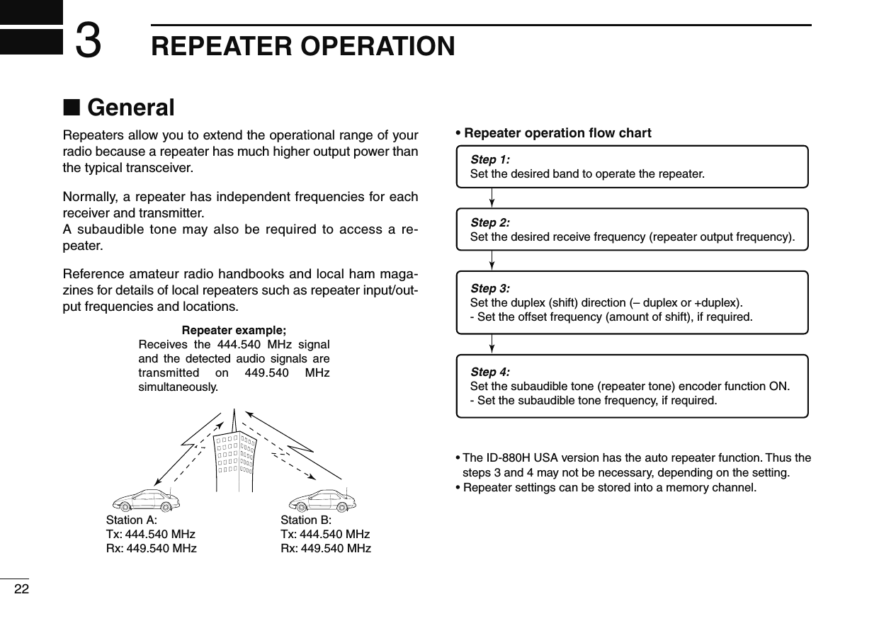
![212BASIC OPERATION12345678910111213141516171819N One-touch PTT functionThe PTT switch can be operated as a one-touch PTT switch (each push toggles between transmit/receive). Using this function you can transmit without pushing and holding the PTT switch.To prevent accidental, continuous transmissions with this function, the transceiver has a time-out timer. See p. 101 for details.PTT-Mz Push [FUNC] then [PRIO 3(PTT-M)] to turn the one-touch PTT function ON. • The activity indicator lights green.x Push [PTT] to transmit and push again to re-ceive. • A beep sounds when transmission is started and a long beep sounds when returning to receive.c Push [FUNC] then [PRIO 3(PTT-M)] to turn the one-touch PTT function OFF. • The activity indicator goes out.](https://usermanual.wiki/ICOM-orporated/316700.User-Manual-2/User-Guide-1074926-Page-1.png)
 for 1 sec. to enter the duplex setting condition.e Rotate [DIAL] to select minus duplex or plus duplex.• “DUP–” or “DUP” appears to indicate the transmit frequency for minus shift or plus shift, respectively.• When the auto repeater function is turned ON (available for the USA version only), steps w to t are not necessary. (p. 35)[DUP]“DUP–” or “DUP” appearsr Push and hold [TONE](M/CALL) for 1 sec. to enter the tone setting condition.t Rotate [DIAL] to turn ON the subaudible tone encoder, accord-ing to repeater requirements, then push [TONE](M/CALL).• “T” appears • 88.5 Hz is set as the default; refer to p. 32 for tone frequency settings.• When the repeater requires a different tone system, see p. 33.[TONE]“T” appearsy Push and hold [PTT] to transmit.• The displayed frequency automatically changes to the transmit frequency (repeater input frequency).• If “OFF” appears, confirm that the offset frequency (p. 34) is set correctly.u Release [PTT] to receive.While receiving While transmittingi Push [MONI] to check whether the other station’s transmit signal can be received directly.o To return to simplex operation, push and hold [DUP](LOW) then rotate [DIAL], to clear the “DUP–” or “DUP” indicator.• Push [DUP](LOW) again to return to frequency indication.!0 To turn OFF the subaudible tone encoder, push and hold [TONE](M/CALL) then rotate [DIAL] until no tone indicator (OFF) appears.• Push [TONE](M/CALL) again to return to frequency indication.](https://usermanual.wiki/ICOM-orporated/316700.User-Manual-2/User-Guide-1074926-Page-3.png)
![243REPEATER OPERATIONDUP–7DUP+8z Set the receive frequency (repeater output fre-quency). (pgs. 16, 17)x Push [DUP– 7(TONE)] to select minus duplex; push [DUP+ 8(TSQLS)] to select plus du-plex. • “DUP–” or “DUP” appears.PushPushc Push [FUNC] then [DUP– 7(TONE)] to turn ON the subaudible tone encoder according to re-peater requirements. • Refer to p. 32 for the tone frequency setting. • When the repeater requires a different tone system, see p. 33.Push ,then .v Push and hold [PTT] to transmit.b Release [PTT] to receive.n Push [MONI 1(BANK)] to check whether the other station’s transmit signal can be received directly.SIMP9ENTCm Push [SIMP 9(TSQL)] to return to simplex opera-tion. • “DUP+” or “DUP–” indicator disappears.Push ,then ., To turn OFF the subaudible tone encoder, push [FUNC] then [ENT C(T-OFF)].Push ,then .](https://usermanual.wiki/ICOM-orporated/316700.User-Manual-2/User-Guide-1074926-Page-4.png)
![253REPEATER OPERATION3N Subaudible tones (Encoder function)D Subaudible tonesq Select mode/channel which you wish to set the subaudible tones to, such as VFO mode or memory/call channel.• The subaudible tone frequency is independently programmed into each mode, band or channel.w Enter “R TONE” in DUP.T menu.MENU ¶ DUP.T ¶ R TONE (p. 63) (Push [MENU ]), (Rotate [DIAL], then push [ ](MONI).)[DIAL][MENU ][ ]e Rotate [DIAL] to select and set the desired subaudible fre-quency, then push [MENU ].r Push [MENU ] again to exit DUP.T menu. NOTE: The subaudible tone encoder frequency can be set in a memory/call channel temporarily. However, the set fre-quency is cleared once another memory channel or VFO mode is selected. To store the tone frequency permanently, overwrite the channel information.SETBz Set mode/channel which you wish to set the subaudible tones for, such as VFO mode or memory/call channel. • The subaudible tone frequency is independently pro-grammed into each mode, band or channel.x Enter “R TONE” in DUP.T menu.MENU ¶ DUP.T ¶ R TONE (p. 63) (Push [SET B(D-OFF)] to enter MENU screen), (Push [Y] or [Z], then push [SET B(D-OFF)].)c Push [Y] or [Z] to select the desired subaudible tone frequency then push [SET B(D-OFF)].Push n Push [CLR A(MW)] to return VFO mode.• Subaudible tone frequency list (unit: Hz)67.069.371.974.477.079.782.585.488.591.594.897.4100.0103.5107.2110.9114.8118.8123.0127.3131.8136.5141.3146.2151.4156.7159.8162.2165.5167.9171.3173.8177.3179.9183.5186.2189.9192.8196.6199.5203.5206.5210.7218.1225.7229.1233.6241.8250.3254.1](https://usermanual.wiki/ICOM-orporated/316700.User-Manual-2/User-Guide-1074926-Page-5.png)
![263REPEATER OPERATIOND DTMF tonesDTMF-S± Push [DTMF-S], then push the keys of the de-sired DTMF digits.• The function indicator lights green.• 0–9, A–D, 1(E) and #(F) are available.• When “ ” is displayed in place of the 100 MHz digit, cancel the DTMF memory encoder in ad-vance. (p. 83)• Push [DTMF-S] again to return the keypad to nor-mal function control.then push desired keys.Push ,-For your convenience! The transceiver has 16 DTMF memory channels for auto-patch operation. See p. 82 for details.D 1750 Hz toneThe microphone has 1750 Hz tone capability, used for ring tone when calling, etc.TONE-1TONE-2z Push [FUNC].• The function indicator lights orange.x Push [1(TONE-1)] to transmit a 1750 Hz tone call signal for 0.5 sec.; push and hold [0(TONE-2)] to transmit a 1750 Hz tone call signal for an arbitrary period.• The function indicator goes out automatically.Push ,then or .](https://usermanual.wiki/ICOM-orporated/316700.User-Manual-2/User-Guide-1074926-Page-6.png)
![273REPEATER OPERATION3N Offset frequencyWhen communicating through a repeater, the transmit fre-quency is shifted from the receive frequency by an amount determined by the offset frequency. Independent offset frequencies can be set for each operating frequency band.q Select the desired mode/channel which you wish to set the offset frequency for, such as VFO mode or memory/call channel.• The offset frequency is independently programmed into each mode, band or channel.w Enter “OFFSET” in DUP.T menu.MENU ¶ DUP.T ¶ OFFSET (p. 63) (Push [MENU ]), (Rotate [DIAL], then push [ ](MONI).)[DIAL][MENU ][ ]e Rotate [DIAL] to set the desired offset frequency, then push [MENU ].• Push [VFO/MHz] to turn 10 MHz or 1 MHz tuning ON and OFFr Push [MENU ] again to exit DUP.T menu.SETBz Push [BAND] to select the desired band. • Enter the desired frequency via the keypad if neces-sary.x Select the desired mode/channel which you wish to set the offset frequency for, such as VFO mode or memory/call channel. • The offset frequency can be independently pro-grammed into each mode, band or channel.c Enter “OFFSET” in DUP.T menu.MENU ¶ DUP.T ¶ OFFSET (p. 63) (Push [SET B(D-OFF)] to enter MENU screen), (Push [Y] or [Z], then push [SET B(D-OFF)].)v Push [Y] or [Z] to set the desired offset. • Direct frequency entry from the keypad is not pos-sible.b Push [CLR A(MW)] to exit set mode. NOTE: The offset frequency can be set in a memory/call channel temporarily. However, the set frequency is cleared once another memory channel or VFO mode is selected. To store the offset frequency permanently, overwrite the channel information.](https://usermanual.wiki/ICOM-orporated/316700.User-Manual-2/User-Guide-1074926-Page-7.png)
![283REPEATER OPERATIONN Auto repeater USA/KOREAN versions onlyThe USA and Korean versions automatically use standard repeater settings (duplex ON/OFF, duplex direction, tone encoder ON/OFF) when the operating frequency falls within or outside of the general repeater output frequency range. The offset and repeater tone frequencies are not changed by the auto repeater function. Reset these frequencies, if necessary.D Frequency range and offset direction• USA versionFREQUENCY RANGE SHIFT DIRECTION147.000–147.395 MHz “DUP+” appears442.000–444.995 MHz “DUP+” appears447.000–449.995 MHz “DUP–” appears145.200–145.495 MHz146.610–146.995 MHz “DUP–” appears• Korean versionFREQUENCY RANGE SHIFT DIRECTION439.000–440.000 MHz “DUP–” appearsq Enter “AUTORP” in FUNC set mode (SET).MENU ¶ SET ¶ FUNC ¶ AUTORP (p. 63) (Push [MENU ]), (Rotate [DIAL], then push [ ](MONI).)[DIAL][MENU ][ ]w Rotate [DIAL] to select the auto repeater setting. [USA version]: • “RPT1” : Activates duplex only. (default) • “RPT2” : Activates duplex and tone. • “OFF” : Auto repeater function is turned OFF. [Korean version]: • “ON” : Activates duplex and tone. (default) • “OFF” : Auto repeater function is turned OFF.e Push [MENU ] to exit the set mode.](https://usermanual.wiki/ICOM-orporated/316700.User-Manual-2/User-Guide-1074926-Page-8.png)
![314DV MODE PROGRAMMING12345678910111213141516171819N Call sign programmingFour types of current call sign memory are available; “MY” (my call sign=your own call sign) “UR” (your call sign=other sta-tion call sign) “RPT1” (access repeater call sign) and “RPT2” (link repeater call sign). Each call sign can be programmed with up to 8 characters.In addition, "MY" can store up to 6 call signs, and "UR" can store up to 60 call signs in the call sign memory. Up to 300 repeater call signs can be stored in the repeater list.D Your own call sign programmingYour own call sign must be programmed for both digital voice and low-speed data communications (including GPS trans-mission).q Enter “MY” in call sign screen.MENU ¶ CALL-S ¶ MY (Push [MENU ]), (rotate [DIAL], then push [ ](MONI).)• MY call sign screen is displayed.w Rotate [DIAL] to select the desired call sign memory, “MY1” to “MY6.” e Push [](LOW) to enter call sign programming mode.• The 1st digit blinks.r Rotate [DIAL] to select the desired character or code.• Push [](LOW) to move the cursor right; push [](CS) to move the cursor left.t Repeat the step r to enter your own call sign.• Up to an 8 digit of call sign can be set.• If an unwanted character is entered, push [](LOW) or [](CS) to select the character, then push [CLR](DR) to erase the se-lected character, or push and hold [CLR](DR) for 1 sec. to erase all characters following the cursor.• To program a note (up to 4 characters, for operating radio type, area, etc.), go to step y, otherwise go to step i.y Push [](LOW) several times to set the cursor beside “/” indication.](https://usermanual.wiki/ICOM-orporated/316700.User-Manual-2/User-Guide-1074926-Page-11.png)
 to store the programmed call sign with note and return to call sign screen.o Push [MENU ] to return to frequency indication.D Station call sign programming Station call sign must be programmed to call a specific sta-tion as well as for repeater operation in both digital voice and low-speed data communications.q Enter “UR” in call sign screen. MENU ¶ CALL-S ¶ UR (Push [MENU ]), (rotate [DIAL], then push [ ](MONI).)• UR (Your) call sign screen is displayed.w Rotate [DIAL] to select the desired call sign memory, “U01” to “U60.”e Push [](LOW) to enter call sign programming mode.• The 1st digit blinks.r Rotate [DIAL] to select the desired character or code.• Push [](LOW) or [](CS) to move the cursor right or left, re-spectively.](https://usermanual.wiki/ICOM-orporated/316700.User-Manual-2/User-Guide-1074926-Page-12.png)
 or [](CS) to select the character, then push [CLR](DR) to erase the se-lected character, or push and hold [CLR](DR) for 1 sec. to erase all characters following the cursor.y Push [ ](MONI) to store the programmed call sign and return to UR (Your) call sign screen.u Push [MENU ] to return to frequency indication. For your informationThe ID-880H has a call sign edit record function.When editing a call sign stored in a call sign memory (or reg-ular memory/call channel), the default setting is to store the edited call sign into blank channel automatically ("FULL" is displayed when all call sign memory is programmed).The edited call sign can be over-written when the setting of the EDIT R (Edit record) is set to OFF or SEL. (p. 132)However, you must manually over-write a reprogrammed call sign in regular memory/call channels (temporary operation without over-writing is possible).D Current repeater call sign programming “RPT1” or “RPT2” can store current call only, and repeater call signs must be stored in the repeater list (p. 39).q Enter “RPT1” or “RPT2” in call sign screen. MENU ¶ CALL-S ¶ RPT1 or RPT2 (Push [MENU ]), (rotate [DIAL], then push [ ](MONI).)• RPT1/RPT2 call sign screen is displayed.w Push [](LOW) to enter call sign programming mode.• The 1st digit blinks.e Rotate [DIAL] to select the desired character or code.• Push [](LOW) or [](CS) to move the cursor right or left, re-spectively.r Repeat the step e to enter the desired repeater call sign.• Up to an 8 digit call sign can be set.• If an unwanted character is entered, push [](LOW) or [](CS) to select the character, then push [CLR](DR) to erase the se-lected character, or push and hold [CLR](DR) for 1 sec. to erase all characters following the cursor.t Push [ ](MONI) to store the programmed call sign and returns to call sign screen.y Push [MENU ] to return to frequency indication.](https://usermanual.wiki/ICOM-orporated/316700.User-Manual-2/User-Guide-1074926-Page-13.png)
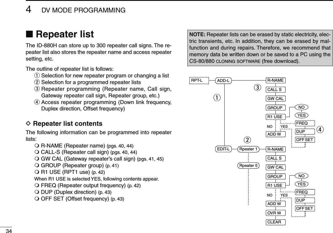
![354DV MODE PROGRAMMING12345678910111213141516171819N Repeater list programmingD New repeater list programmingq Enter “ADD-L” in RPT-L menu.MENU ¶ RPT-L ¶ ADD-L (Push [MENU ]), (Rotate [DIAL], then push [ ](MONI).)• “R-NAME” appears.Repeater name programming (R-NAME)w Push [](MONI) to enter the repeater name programming state. See p. 44 for repeater name programming details.• Repeater name programming screen is displayed.e Program the repeater name, then push [ ](MONI) to exit the state.• Rotate [DIAL] to select the desired character, number, symbol or space. • Push [](LOW)/[](CS) to move the cursor right or left, respec-tively. r Rotate [DIAL] to select the next content (repeater call sign programming).Repeater call sign programming (CALL S)t Push [](MONI) to enter the repeater call sign program-ming state. See p. 44 for repeater call sign programming details.• Repeater call sign programming screen is displayed.y Program the repeater call sign, then push [ ](MONI) to exit the state.• Rotate [DIAL] to select the desired character, number, symbol (‘/’only) or space. • Push [](LOW)/[](CS) to move the cursor right or left, respec-tively. u Rotate [DIAL] to select the next content (gateway repeater call sign programming). CONVENIENT!After you program the repeater call sign, you can skip the other programming and store the list.± Push and hold [S.MW](M/CALL) for 1 sec. to enter mem-ory write state, then push [](MONI) to store the list.](https://usermanual.wiki/ICOM-orporated/316700.User-Manual-2/User-Guide-1074926-Page-15.png)
 to enter the gateway repeater call sign programming state. See p. 45 for gateway repeater call sign programming details.• Gateway repeater call sign programming screen is displayed.• Programmed repeater call sign is displayed and the 8th digit is automatically added or replaced to “G.”o When the programmed repeater has gateway capability, push [](MONI) to exit gateway repeater setting and skip to !2. Or when the programmed repeater has a different repeater for gateway communication, follow the next step !0.• When the repeater does not have a gateway repeater, follow the next step !0, too.!0 Program the other gateway repeater call sign, then push [](MONI) to exit the state.• Rotate [DIAL] to select the desired character, number, symbol (‘/’only) or space. • Push [](LOW)/[](CS) to move the cursor right or left, respec-tively. • Up to an 8 digit call sign can be set, but 8th digit must be set to “G.”• When the repeater does not have a gateway repeater, push and hold [CLR](DR) for 1 sec. to erase all characters.!1 Rotate [DIAL] to select the next content (repeater group programming).Repeater group programming (GROUP)!2 Push [](MONI) to enter the repeater group programming state.• Repeater group programming screen is displayed.• Selected group number appears and group indicator blinks.!3 Rotate [DIAL] to select the desired repeater group.• Selected group number appears and group indicator blinks.!4 Push [ ](MONI) to set the repeater group and exit the state.!5 Rotate [DIAL] to select the next content (access repeater setting).](https://usermanual.wiki/ICOM-orporated/316700.User-Manual-2/User-Guide-1074926-Page-16.png)
 to enter the access repeater program-ming state.• Access repeater programming screen is displayed.!7 Rotate [DIAL] to select “YES” or “NO.”• When “NO” is selected, the repeater can be selected as the link repeater (RPT2) only in DR mode.• When “YES” is selected, the repeater can be selected as the ac-cess repeater (RPT1) and link repeater (RPT2) in DR mode.!8 Push [ ](MONI) to exit the state.± When “NO” is selected at step !7, skip to step #1.± When “YES” is selected at step !7, push [](2) or [](8) to select the access repeater (RPT1) programming. Follow the next step !9 to program the repeater.Frequency programming (FREQ)This content appears when R1 USE is selected YES.!9 Push [ ](MONI) to enter the frequency programming state.• Frequency programming screen is displayed.@0 Rotate [DIAL] to select the frequency band.• The selected number blinks at 1st digit.• Push [](LOW) to move the cursor right; push [](CS) to move the cursor left. • Push and hold [CLR](DR) for 1 sec. to clear the displayed fre-quency.@1 Repeat step @0 until the repeater frequency is set.@2 Push [ ](MONI) to set the frequency and exit the state.@3 Rotate [DIAL] to select the next content (duplex direction programming).](https://usermanual.wiki/ICOM-orporated/316700.User-Manual-2/User-Guide-1074926-Page-17.png)
 to enter the duplex direction setting state.• Duplex direction setting screen is displayed.@5 Rotate [DIAL] to select the duplex direction.@6 Push [ ](MONI) to set the duplex direction and exit the state.@7 Rotate [DIAL] to select the next content (offset frequency programming).Offset frequency programming (OFF SET)This content appears when RPT1 U is selected YES.@8 Push [ ](MONI) to enter the offset frequency program-ming state.• Offset frequency programming screen is displayed.@9 Rotate [DIAL] to select the offset frequency.• The selected number blinks.• Push [](LOW) to move the cursor right; push [](CS) to move the cursor left. • Push and hold [CLR](DR) for 1 sec. to clear the displayed fre-quency.#0 Push [ ](MONI) to set the offset frequency and exit the state.Storing the repeater list (ADD W)#1 Rotate [DIAL] to select the store operation.#2 Push [](MONI) to enter storing state.• “ADD W OK?” appears.#3 Push [ ](MONI) again to store the list.](https://usermanual.wiki/ICOM-orporated/316700.User-Manual-2/User-Guide-1074926-Page-18.png)
 to enter the repeater name programming state.• Repeater name programming screen is displayed.• The 1st digit blinks.w Rotate [DIAL] to select the desired character, number, symbol or space.• The selected character blinks.• Push [](LOW) to move the cursor right; push [](CS) to move the cursor left. • Push [CLR](DR) to erase the selected character, or push and hold [CLR](DR) for 1 sec. to erase all characters following the cursor.e Repeat step w until the desired repeater name is pro-grammed.• Up to an 8 digit name can be set.r Push [ ](MONI) to program the repeater name and exit the state. Repeater call sign programming (CALL S)q Push [ ](MONI) to enter the repeater call sign program-ming state. • Repeater call sign programming screen is displayed. • The 1st digit blinks.w Rotate [DIAL] to select the desired character, number or symbol (‘/’ only).• The selected character blinks.• Push [](LOW) to move the cursor right; push [](CS) to move the cursor left. • Push [CLR](DR) to erase the selected character, or push and hold [CLR](DR) for 1 sec. to erase all characters following the cursor.e Repeat step w until the desired repeater call sign is pro-grammed.• Up to an 8 digit call sign can be set.r Push [ ](MONI) to program the repeater call sign and exit the state.](https://usermanual.wiki/ICOM-orporated/316700.User-Manual-2/User-Guide-1074926-Page-19.png)
 to enter the gateway repeater call sign programming.• Gateway repeater call sign programming screen is displayed.• Programmed repeater call sign is displayed, then the 1st char-acter blinks.• The 8th digit is automatically added or replaced to “G.”w Rotate [DIAL] to select the desired character, number, symbol (‘/’ only) or space.• The selected character blinks.• Push [](LOW) to move the cursor right; push [](CS) to move the cursor left. • Push [CLR](DR) to erase the selected character, or push and hold [CLR](DR) for 1 sec. to erase all characters following the cursor.e Repeat step w until the desired repeater call sign is pro-grammed. • Up to an 8 digit call sign can be set, but 8th digit must be set to “G.”r Push [ ](MONI) to program the gateway repeater call sign and exit the state.N Changing a repeater listThis function re-programs a repeater list’s contents. This is useful when already programmed contents are mistaken or some contents are added to the list.q Enter “EDIT-L” in RPT-L menu.MENU ¶ RPT-L ¶ EDIT-L (Push [MENU ]), (Rotate [DIAL], then push [ ](MONI).)• Programmed repeater name appears.SKIP indicatorSKIP indicator shows the selected repeater can not be usedfor access repeater (RPT1) in DR mode as follow reasons. • “R1 USE” is set to “NO”• Either “FREQ” (frequency) or “DUP” (duplex direction) has not been programmedw Push and hold [BAND] for 1 sec. to enter group selection, rotate [DIAL] to select the desired group (0–9), then push [BAND].](https://usermanual.wiki/ICOM-orporated/316700.User-Manual-2/User-Guide-1074926-Page-20.png)
![414DV MODE PROGRAMMING12345678910111213141516171819e Rotate [DIAL] to select the desired repeater list to be changed.r Push [](MONI) to enter the list.t Rotate [DIAL] to select the content to be changed, then push [](MONI) to enter the content and reprogram the content (see pages 40–43 for new repeater list program-ming details).y After programming is finished, rotate [DIAL] to select “ADD W” or “OVR W,” then push [](MONI).When “ADD W” is selected;• “ADD W OK?” appears.When “OVR W” is selected;• “OVR W OK?” appears.u Push [ ](MONI) again to store the list.N Clearing a repeater listContents of programmed list can be cleared (erased).q Enter “EDIT-L” in RPT-L menu.MENU ¶ RPT-L ¶ EDIT-L (Push [MENU ]), (Rotate [DIAL], then push [ ](MONI).)• Programmed repeater name appears.w Rotate [DIAL] to select the desired repeater list to be erased.• Push and hold [BAND] for 1 sec. to enter group selection, rotate [DIAL] to select the desired group (0–9) then push [BAND].e Push [ ](MONI) to enter the list.r Rotate [DIAL] to select “CLEAR,” then push [ ](MONI).• “CLEAR OK?” appears.t Push [ ](MONI) again to clear the list.](https://usermanual.wiki/ICOM-orporated/316700.User-Manual-2/User-Guide-1074926-Page-21.png)
![42DV MODE OPERATION5N Digital mode operationThe ID-880H can be operated in digital voice mode and low-speed data operation for both transmit and receive. It can also be connected to a GPS receiver (compatible with an RS-232 output/NMEA format/4800 bps/9600 bps) to transmit/receive position data.N Current call sign settingSet the current call sign for DV operation as follows.q Enter “CALL-S” in MENU screen.MENU ¶ CALL-S (Push [MENU ]), (Rotate [DIAL], then push [ ](MONI).)• Call sign screen is displayed.w Rotate [DIAL] to select the desired call sign group, “UR,” RPT1,” “RPT2” or “MY,” then push [](MONI).• Current call sign is displayed.Quick entryPush [CS] to enter the current call sign mode. See next page for details.• Call sign groupUR : Station call signs (U01–U60), “CQCQCQ” (U--) or repeater CQ* (R-L) can be selected.* ‘/’ plus repeater call sign (R-L), ‘/’ stands for “CQCQCQ”RPT1 : “NOTUSE”* (R--) or repeater call signs (R-L) can be selected.* Direct communication (NOT USE repeater)RPT2 : “NOTUSE”* (R--) or repeater call signs (R-L) can be selected.* Direct communication or using area repeater only (NOT USE link repeater)MY : My call signs (MY1–MY6) can be selected.e Rotate [DIAL] to select the desired call sign.Or push [](LOW) to enter the current call sign program-ming state (pgs. 36–38).• When “UR,” “RPT1” or “RPT2” is selected at step w, push [BAND] several times to select the repeater call sign groups.• When “RPT1” or “RPT2” is selected at step w, push [M/CALL] to toggle the call sign and repeater name indications.r Push [ ](MONI) to set the selected call sign to the current call sign and exit the state.t Repeat steps w to r to set the other current call sign.y Push [MENU ] to return to frequency indication.](https://usermanual.wiki/ICOM-orporated/316700.User-Manual-2/User-Guide-1074926-Page-22.png)
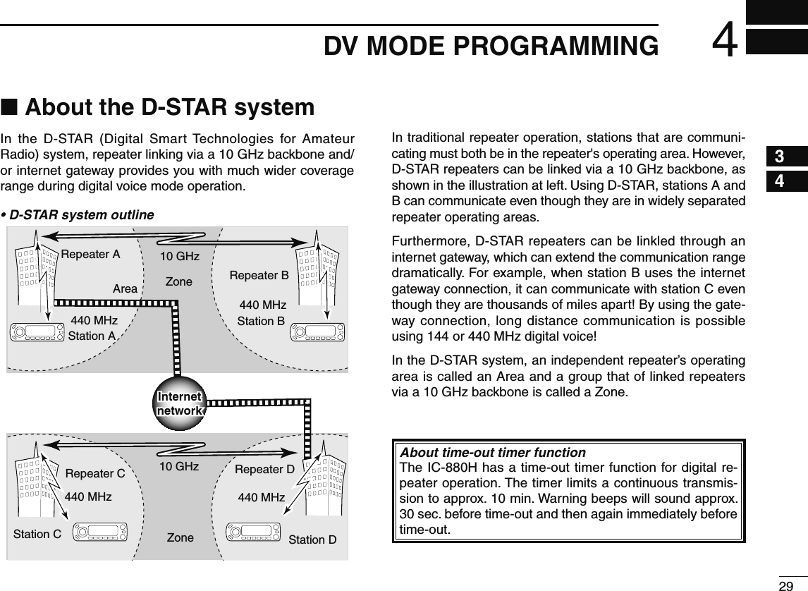
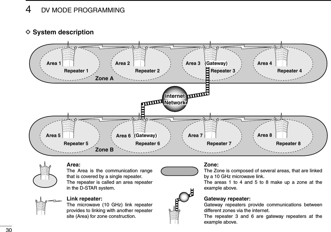
![435DV MODE OPERATION12345678910111213141516171819D Confirming current call signq Push [CS] to enter the current call sign mode.• Current UR (your) call sign is displayed.Appears momentarilyw Rotate [DIAL] to select and confirm the other current call sign.• (“UR”), “R1,” “R2” and “MY” appears in sequence.• When “R1” or “R2” is selected, push and hold [M/CALL] for 1 sec. to toggle the call sign and repeater name indications.When changing the call signq Push [ ](5) to enter the call sign selection mode.w Rotate [DIAL] to select the desired call sign, then push [](5).• When “UR,” “R1” or “R2” is selected, push [BAND] several times to select the repeater call sign groups.e Push [CS] again to return to frequency indication.N Receiving a D-STAR repeaterWhen the ID-880H receives a signal from a D-STAR repeater, it receives four call sign: caller’s call sign, called call sign, repeater call sign 1 (the repeater that caller accessed), and repeater call sign 2 (the liked repeater). You can copy the re-ceived call signs to current call signs, and you can also reply to a call.Station A Station BRepeater449.700 MHz444.700 MHz 444.700 MHz449.700 MHzUplinkDownlink(transmitting freq.)(receiving freq.)• Presettingq Set the desired repeater frequency. (p. 23)• Select output power, if desired. (p. 27)w Set the shift direction of the transmit frequency. (DUP– or DUP; see p. 31 for details.)• When the auto repeater function is in use (U.S.A. and Korean versions only), this selection is not necessary. (p. 32)e Select DV mode. (p. 25)r When signal is received, display indicates received call sign. See next page for information about received call signs.](https://usermanual.wiki/ICOM-orporated/316700.User-Manual-2/User-Guide-1074926-Page-23.png)
![445DV MODE OPERATIONN Received call signWhen a call is received in DV mode, the calling station and the repeater call signs being used can be stored into the re-ceived call record. The stored call signs are viewable in the following manner. Up to 20 calls can be recorded.D Desired call record indicationq Enter RX call sign set mode.MENU ¶ RX-CAL (Push [MENU ]), (Rotate [DIAL], then push [ ](MONI).)• RX call sign screen is displayed.w Rotate [DIAL] to select the desired record channel.e To confirm the received call, push [ ](MONI) several times to select the desired call sign from CALLER, / (CALLER’s note), CALLED, RXRPT1 and RXRPT2.CALLER : The station call sign that made a call./ : 4 character note with call sign that made a call.CALLED : The station call sign called by the caller.RXRPT1 : The repeater call sign used by the caller station.RXRPT2 : The repeater call sign linked from RXRPT1.r Push [MENU ] to return to frequency indication. For your informationWhen receiving a call, the received station call sign is auto-matically displayed and scrolled in sequence at the frequency display.This can be turned OFF in DISP set mode. (p.132)PushCall record channelMONI NOTE: When a call is received in DV mode when the power save function is activated, the call sign may not be received correctly. This is normal, not a malfunction, because the call sign information cannot be detected during power save. Turn the power save function OFF (p. 123) if you want to receive a call sign correctly even in stand-by operation.](https://usermanual.wiki/ICOM-orporated/316700.User-Manual-2/User-Guide-1074926-Page-24.png)
 for 1 sec.The received call sign is displayedwhile pushing and holding with rotating .• Set your own call sign (MY) in advance. (pgs. 36, 47, 48)• The call sign in “CALLER” is stored as “UR,” “RXRPT1” is stored as “R2” and “RXRPT2” is stored as “R1.”• Error beeps sound when a call sign is received incorrectly, and no call sign is set in this case.w Push [PTT] to transmit; release to receive.Important!Setting call signs with the “One-touch reply using the call record” operation as at left are for temporary operation only. Therefore, the set call signs will be over-written when another call record is used to set call signs.• Never saved into a call sign memory.If you want to save the set call signs, see “Copying the call record contents into call sign memory” (p. 51) for details.For your informationWhen a call specifying your call sign is received, the call signs of the calling station and the repeater it is using can be automatically used for operation.• When “CALL W (RX call sign auto write)” (p. 131) is set to “AUTO,” the station call sign in “CALLER” is set to “UR” au-tomatically.• When “RPT W (Repeater call sign auto write)” (p. 131) is set to “AUTO,” the repeater call sign in “RXRPT1” is stored as “R2” and “RXRPT2” is stored as “R1” automatically.](https://usermanual.wiki/ICOM-orporated/316700.User-Manual-2/User-Guide-1074926-Page-25.png)
![465DV MODE OPERATIONN Copying the call signD Copying the call sign memory contentsThis function is convenient when or modifying a part of the current call sign.q During DV mode operation, enter call sign menu.MENU ¶ CALL-S (Push [MENU ]), (Rotate [DIAL], then push [ ](MONI).)w Rotate [DIAL] to select “UR,” then push [ ](MONI).e Rotate [DIAL] to select the desired call sign channel to be copied.• U01–U60 are available.• When “AUTO” is set to “EDIT R” itemr Push [](LOW) to select the call sign programming mode.• The 1st digit of the selected call sign blinks.Blank channel is selectedautomatically.t Modify the selected call sign as described in “Station call sign programming” (p. 37).y Push [](MONI) to store the modified call sign into the selected blank channel.NOTE: Make sure that the “EDIT R (EDIT RECORD)” item in DV set mode is set to “AUTO” or “SEL” in advance. (p. 132) NOTE: The message “FULL” is displayed when no blank channel is available in station call sign memory. In this case, select the desired call sign channel number as described in step u is set to “• When “SEL” is set to “EDIT R” item below.• When “SEL” is set to “EDIT R” itemr Push [](LOW) to select the call sign programming mode. • The 1st digit of the selected call sign blinks.t Modify the selected call sign as described in “Station call sign programming” (p. 37).y Push [ ](MONI). • Call sign channel number blinks.Call sign channel numberblinks.u Rotate [DIAL] to select the desired call sign channel to store.i Push [](MONI) to store the modified call sign into the selected channel.](https://usermanual.wiki/ICOM-orporated/316700.User-Manual-2/User-Guide-1074926-Page-26.png)
![475DV MODE OPERATION12345678910111213141516171819D Copying the call record contents into call sign memoryThis is a way to copy the call record contents (“CALLER,” “RXRPT1” and “RXRPT2”) into call sign memory (“UR,” “R1” and “R2”) at the same time or individually. q Enter RX CAL (RX call sign) mode.MENU ¶ RX CAL (Push [MENU ]), (Rotate [DIAL], then push [ ](MONI).)• RX call sign screen is displayed.w Rotate [DIAL] to select the desired record channel.e Push [](MONI) several times to select the desired call sign from CALLER, / (CALLER’s note), CALLED, RXRPT1 and RXRPT2.CALLER : The station call sign that made a call./ : 4 character note with call sign that made a call.CALLED : The station call sign called by the caller.RXRPT1 : The repeater call sign used by the caller station.RXRPT2 : The repeater call sign linked from RXRPT1.r Push [](LOW) to enter copy select mode. • Copy select screen is displayed.t Rotate [DIAL] to select the desired call sign to be copied from “C ALL,” “C UR01”–“C UR60,” “C R-L” and “CLEAR.”• “C ALL” selection won’t appear when either station call sign memory or repeater list has no blank channel.y Push [ ](LOW) to copy the selected record’s contents into the appropriate call sign memory or repeater lists.C ALL : Copy the caller call sign in “CALLER” to “UR” (sta-tion call sign memory) and the repeater call sign in “RXRPT1” / “RXRPT2” to the repeater lists. This selection won’t appear when either station call sign memory or repeater list has no blank channel.C UR01– : C UR60 : Copy the caller call sign in “CALLER” to “UR” (sta-tion call sign memory). This selection appears when entering the copy select mode (step r) from “CALLER” only.C R-L : Copy the repeater call sign in “RXRPT1” / “RXRPT2” to the repeater lists. This selection appears when entering the copy select mode (step r) from “RXRPT1” or “RXRPT2” only.CLEAR : Clear (erase) the selected call record contents.u Push [MENU ] to return to frequency indication.](https://usermanual.wiki/ICOM-orporated/316700.User-Manual-2/User-Guide-1074926-Page-27.png)
![485DV MODE OPERATIONN DR (D-STAR Repeater) mode operationDR (D-STAR Repeater) mode is used for D-STAR repeater operation. In this mode, you can select the pre-programmed repeaters and UR (your) call sign by using [DIAL].• DR mode operation flow chartStep 3: (RPT2 selection)Select link repeater, gateway repeater or access repeater only (NOT USE).Push PTT to transmit, release to receive.Step 1: (RPT1 selection)Select the access repeater. - Access repeater scan is useful to find a repeater.Step 2: (UR call sign selection)Select UR call sign.Calling a CQIn same area: CQCQCQTo other area: Repeater nameIn same area: NOT USEIn same zone: Repeater nameTo different zone: GWCalling a specific station• Repeater settings can be stored into a memory channel. D Access repeater scanq Push [DR] to select DR mode.• DV mode is selected automatically.w Push and hold [SCAN](VFO/MHz) for 1 sec. to start the scan.• Scan pauses when a signal is received.• Rotate [DIAL] to change the scanning direction, or resumes manually.• Push [V/MHz] to stop the scan.[SCAN]During access repeater scan](https://usermanual.wiki/ICOM-orporated/316700.User-Manual-2/User-Guide-1074926-Page-28.png)
![495DV MODE OPERATION12345678910111213141516171819• Skip settingUnwanted access repeater can be skipped for rapid selection or scan.q Enter “EDIT-L” in RPT-L menu.MENU ¶ RPT-L ¶ EDIT-L (Push [MENU ]), (Rotate [DIAL], then push [ ](MONI).)• Programmed repeater name appears.w Rotate [DIAL] to select the desired access repeater to be skipped.• Push and hold [BAND] for 1 sec. to enter group selection, rotate [DIAL] to select the desired group (0–9) then push [BAND].e Push [DR] to toggle the skip setting ON and OFF.• “SKIP” appears when the channel is set as skip channel.SKIP indicatorSKIP indicator shows the selected repeater can not be usedfor access repeater (RPT1) in DR mode as follow reasons. • “R1 USE” is set to “NO”• Either “FREQ” (frequency) or “DUP” (duplex direction) has not been programmed](https://usermanual.wiki/ICOM-orporated/316700.User-Manual-2/User-Guide-1074926-Page-29.png)
![505DV MODE OPERATIONN Calling CQSTEP 1 (RPT1 selection)q Push [DR] to enter DR mode.[DR]AppearsRepeater selection indicatorw Select the repeater group.Selecting the repeater groupq Push and hold [BAND] for 1 sec., then rotate [DIAL] to select the desired repeater group.• Only assigned groups from GRP 1–GRP 9 and GRP 0 are selectable.[DIAL] [BAND] Group indicator blinksw Push [BAND] again to release the group selection.e Rotate [DIAL] to select the access repeater.• Only repeaters that have access repeater settings programmed are selectable.• Group indicator appears momentarily when rotating [DIAL].• Access repeater scan can be used for the selection. (p. 48)[DIAL]STEP 2 (UR call sign selection)r Push and hold [UR](DR) for 1 sec. to enter the your call sign selection.[UR]UR selection indicatort Select the group as step w.• Only assigned GRP 1–GRP 9, GRP 0, GRP UR and GRP CQ are selectable.• UR (your) call signs are selectable in GRP UR. • “CQCQCQ” is selectable in GRP CQ.• Push [BAND] several times to select “GRP UR,” “GRP CQ” and “GRP RP.”](https://usermanual.wiki/ICOM-orporated/316700.User-Manual-2/User-Guide-1074926-Page-30.png)
![515DV MODE OPERATION12345678910111213141516171819D Calling CQ in the same area (Area CQ)My call sign:JA3YUACQAreaZoneRepeater q: NARA43 (JP3YHL)q w e rContinued instruction from step t on page 54.y Push [BAND] several times to select “GRP CQ,” then “CQCQCQ” is selected as UR (your) call sign automati-cally.• The link repeater (RPT2) setting is set to “NOT USE” automati-cally.u Push [PTT] to transmit; release to receive.D Calling CQ in another area (Zone CQ/Different zone CQ)• Calling CQ in the same zone (Zone CQ)My call sign:JA3YUARepeater q : NARA43 (JP3YHL)Repeater r : IKOMA43 (JP3YHJ)CQq w e rAreaZone• Calling CQ in another zone (Different zone CQ)Repeater q : Repeater e : Repeater u : CQq w e rt y u iMy call sign:JA3YUAGatewayGatewayAreaZone AZone BNARA43(JP3YHL)HIRANO43(JP3YHH G)HAMA43(JP1YIU)Continued instruction from step t on page 54.y Rotate [DIAL] to select a desired repeater name.• Push [BAND] several times to select “GRP RP” or push [0]–[9] to select the repeater group in advance.Calling CQ in the same zone (Zone CQ)The link repeater (RPT2) is set to the selected repeater auto-matically.Calling CQ in another zone (Different zone CQ)The link repeater (RPT2) is set to the preset gateway repeater automatically.u Push [PTT] to transmit; release to receive.](https://usermanual.wiki/ICOM-orporated/316700.User-Manual-2/User-Guide-1074926-Page-31.png)
![525DV MODE OPERATIONN Calling a specific stationSTEP 1 (RPT1 selection)q Push [DR] to enter DR mode.[DR]AppearsRepeater selection indicatorw Select the repeater group.Selecting the repeater groupq Push and hold [BAND] for 1 sec., then rotate [DIAL] to select the desired repeater group.• Only assigned groups from GRP 1–GRP 9 and GRP 0 are selectable.[DIAL] [BAND] Group indicator blinksw Push [BAND] again to release the group selection.• Push [0]–[9] to select the repeater group directly.e Rotate [DIAL] to select the access repeater.• Only repeaters that have access repeater settings programmed are selectable.• Group indicator appears momentarily when rotating [DIAL].• Access repeater scan can be used for the selection. (p. 48)[DIAL]STEP 2 (UR call sign selection)r Push and hold [UR](DR) for 1 sec. to enter the your call sign selection.[UR]UR selection indicatort Rotate [DIAL] to select a specific station call sign.• Push [BAND] several times to select “GRP UR” in advance.](https://usermanual.wiki/ICOM-orporated/316700.User-Manual-2/User-Guide-1074926-Page-32.png)
 for 1 sec. to enter the link re-peater (RPT2) selection.u Rotate [DIAL] to select “NOT USE.”i Push [UR](DR) to exit the link repeater selection.o Push [PTT] to transmit; release to receive.D Calling a specific station in the same zone (Zone call)My call sign:JA3YUAStation call sign:JG3YMKRepeater q : NARA43 (JP3YHL)Repeater r : IKOMA43 (JP3YHJ)q w e rContinued instruction from step t on page 52.STEP 3 (RPT2 selection)y Push and hold [UR](DR) for 1 sec. to enter the link re-peater (RPT2) selection.i Rotate [DIAL] to select the link repeater in the same zone.• Only repeaters that have programmed same gateway repeater appear.o Push [UR](DR) to exit the link repeater selection.o Push [PTT] to transmit; release to receive.](https://usermanual.wiki/ICOM-orporated/316700.User-Manual-2/User-Guide-1074926-Page-33.png)
 for 1 sec. to enter the link re-peater (RPT2) selection.u Rotate [DIAL] to select the preset gateway repeater “GW.”• Only repeaters that have programmed same gateway repeater appear.i Push [UR](DR) to exit the link repeater selection.o Push [PTT] to transmit; release to receive.D Calling a specific station in another zone (Different zone call)](https://usermanual.wiki/ICOM-orporated/316700.User-Manual-2/User-Guide-1074926-Page-34.png)
![555DV MODE OPERATION12345678910111213141516171819D Confirming the settingq Push [CS] to enter the setting confirmation screen.• Either UR (your), “R1” or “R2” call sign is displayed.Appears momentarilyw Rotate [DIAL] to select and confirm the other current call sign.• “UR,” “R1,” “R2,” “MY” and “FRQ” appears in sequence.e Push [M/CALL] to toggle the name indication and call sign indication.• Name indication is available only for repeater call signs that have programmed repeater names.r Push [CS] again to exit the setting confirmation screen.](https://usermanual.wiki/ICOM-orporated/316700.User-Manual-2/User-Guide-1074926-Page-35.png)