ICOM orporated 316700 VHF/UHF Amateur Transceiver User Manual ID 880H Draft
ICOM Incorporated VHF/UHF Amateur Transceiver ID 880H Draft
UserManual.wiki
>
ICOM orporated
>
316700 User Manual
>
User Manual 4
Contents
1.
User Manual 1
2.
User Manual 2
3.
User Manual 3
4.
User Manual 4
User Manual 4
Navigation menu
Upload a User Manual
Namespaces
Wiki Guide
HTML
PDF
Info
Views
User Manual
Discussion / Help
Navigation
![11212 MENU SCREEN OPERATIOND Weather alert U.S.A. version onlyTurns weather alert function ON and OFF. (p. 000)(default: OFF)D Memory bank link function Sets the memory bank link function ON and OFF (default). The link function provides continuous bank scan, scanning all contents in the selected banks during bank scan.• Bank link settingq Rotate [DIAL] to select the bank that you want to change.w Push [ ](MONI)* to enter bank setting.e Rotate [DIAL] to select the setting. r Push [ ](MONI)* to set and return to the BANK selection screen.t Rotate [DIAL] to select next bank and repeat steps w to r, or push [MENU ] to exit scan set mode.](https://usermanual.wiki/ICOM-orporated/316700.User-Manual-4/User-Guide-1074928-Page-1.png)
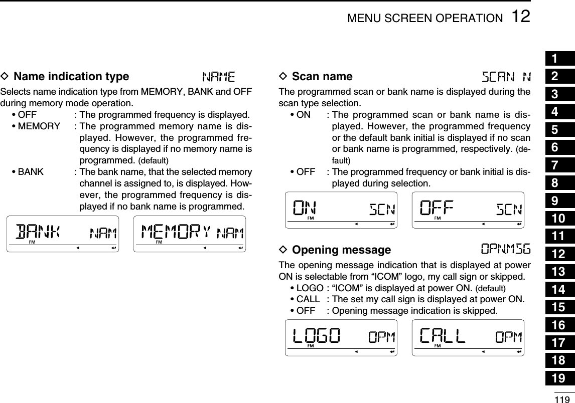
![11312MENU SCREEN OPERATION12345678910111213141516171819D Program scan link function Sets the program scan link function ON and OFF (default). The link function provides continuous program scan in the selected program scan number during program scan.• Program scan link settingq Rotate [DIAL] to select the program scan link channel, P0 to P9, that you want to change.w Push [ ](MONI)* to enter program scan link setting.e Rotate [DIAL] to select “ADD” to adding or “CLEAR” to deleting from programmed scan link setting. • “LINK” for programmed scan linked number confirmation (p. 000) and “NAME” for programmed scan link name setting (p. 000) items also available.r Push [ ](MONI)* then rotate [DIAL] to select the desired programmed scan number to be linked (if “ADD” is selected in step e) or to be deleted from the link (if “CLEAR” is se-lected in step e). • “ADD” selection; The programmed scan numbers, that has not been linked in the selected program link channel, are only be displayed/selected. • “CLEAR” selection; The programmed scan numbers, that has been linked in the se-lected program link channel, are only be displayed/selected. • Push [Ω] (CS) to cancel the selection.t Push [ ](MONI)* to add/delete the setting. • Return to the previous indication as step e.y Repeat steps e to t to continuing the program scan link channel setting or push [MENU ] to exit MENU screen operation.](https://usermanual.wiki/ICOM-orporated/316700.User-Manual-4/User-Guide-1074928-Page-2.png)
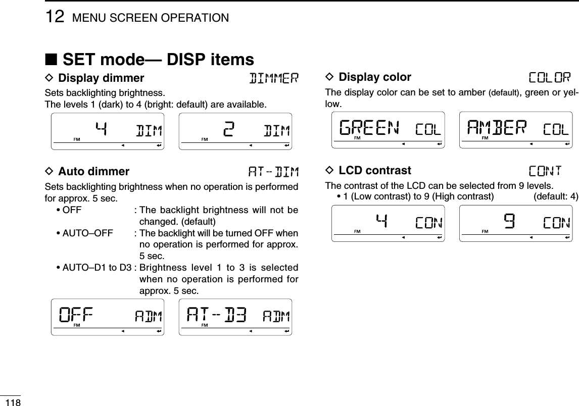
![11412 MENU SCREEN OPERATIONN SET mode— FUNC itemsD Squelch delay timer Selects squelch delay from short and long to prevent re-peated opening and closing of the squelch during reception of the same signal.• SHORT : Short squelch delay. (default)• LONG : Long squelch delayD Attenuator The attenuator prevents distortion of a desired signal by very strong RF signals near the desired frequency or when very strong electric fields, such as from a broadcasting station, are present at your location.Select the attenuator function ON and OFF (default).D Mic sens level Selects the microphone sensitivity from HIGH and LOW to suit your preference. (default : USA version; LOW, Other versions; HIGH)D ALC Sets the ALC (Automatic Level Control) function ON and OFF (default).The ALC function reduces the microphone again automati-cally when the transmission audio is distorted.D PTT lock Turns the PTT lock function ON and OFF.Transmission with [PTT] is inhibited when ON is selected to prevent accidental transmission, etc. (default: OFF)](https://usermanual.wiki/ICOM-orporated/316700.User-Manual-4/User-Guide-1074928-Page-3.png)
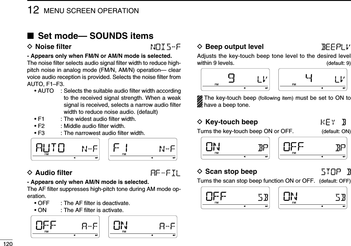
![11612 MENU SCREEN OPERATIOND Fan control Selects the cooling fan control condition from AUTO, FAST, MID and SLOW.• AUTO : The fan rotates during transmit and for 2 min. after transmission. (default)• FAST : The fan continuously rotates at fast speed.• MID : The fan continuously rotates at medium speed.• SLOW : The fan continuously rotates at low speed.D Active band Allows continuous frequency selection of the operating fre-quency across all bands.• SINGLE : A single operating frequency can be selected within the current band. Push [BAND] for band selection in this case.• ALL : The operating frequency can be selected con-tinuously. (default)D Mic UP/DN / Sets the assigning function to the [UP]/[DN] keys on the op-tional HM-154.Assignable functions:UP* (default) DOWN† (default)MENU (as [MENU ]) V/MHZ (as [VFO/MHz])BAND (as [BAND MODE]) SMW (as [S.MW MW])M/CALL (as [M/CALL]) DR (as [DR])CS (as [CS]) LOW (as [LOW])MONI (as [MONI])*Available for “MIC-UP” only; †Available for “MIC-DN” onlyD Packet speed Selects the data transmission speed for packet operation from 1200 bps (default) and 9600 bps.](https://usermanual.wiki/ICOM-orporated/316700.User-Manual-4/User-Guide-1074928-Page-5.png)
![11712MENU SCREEN OPERATION12345678910111213141516171819D Data speed Selects the data communication speed between [DATA] jack and the connected GPS, PC, etc. from 4800 bps and 9600 bps (default).D Auto power OFF The transceiver can be set to automatically turn OFF after a specified time period with a beep when no key operations are performed.30 min., 60 min, 90 min, 120 min and OFF (default) can be specified. The specified time period is retained even when the transceiver is turned OFF by the auto power OFF func-tion. To cancel the function, select “OFF” in this item.](https://usermanual.wiki/ICOM-orporated/316700.User-Manual-4/User-Guide-1074928-Page-6.png)
![12212 MENU SCREEN OPERATIONN DV set mode itemsD Auto reply This function replies to an individual station call even you are away from the transceiver.After a manual transmission (pushing [PTT]), the Auto Reply setting returns to OFF automatically.• OFF : No reply is performed even if a call is received. (default)• ON : Sets the caller's call sign and replies to the call with the programmed own call sign.D DV data TX During low-speed data operation, auto data transmission function is available. This function transmits when data has been input from PC via the [DATA] jack.• PTT : Data from [DATA] transmits when [PTT] is pushed. (default)• AUTO : Data from [DATA] transmits automatically.D Digital monitor Sets the desired monitoring mode during digital mode opera-tion from “Auto,” “Digital” and “Analog.”• AUTO : The transceiver sets monitoring mode to FM and DV according to the received signal. (default)• DIGI : Monitors in DV mode.• ANALOG : Monitors in FM mode.D Digital repeater setting When accessing a digital repeater with a call sign different than is programmed, the repeater call sign can be stored into “RPT1” and/or “RPT2” automatically by reading the repeat-er’s transmission. The previously stored repeater’s call sign can be recalled when selecting the repeater call sign.(default: ON)](https://usermanual.wiki/ICOM-orporated/316700.User-Manual-4/User-Guide-1074928-Page-11.png)
![12712MENU SCREEN OPERATION12345678910111213141516171819 Sentence formatter setting q Select “DVG” in GPS transmission item, then push [ ] (MONI) to enter the sentence formatter selection.w Rotate [DIAL] to select the desired sentence formatter. • RMC, GGA, GLL, GSA, VTG and GSV are selectable.e Push [ ] (MONI) to enter the desired sentence formatter selection.r Rotate [DIAL] to select ON/OFF. • Default setting for sentence formatterSentence formatter Default Sentence formatter DefaultRMC OFF GSA OFFGGA ON VTG OFFGLL OFF GSV OFFt Push [ ] (MONI) to store the selection.y Rotate [DIAL] to select next sentence and repeat steps w to t, or push [MENU ] to return to frequency indica-tion. • Only four sentence formatters can be activated at the same time. GPS-A Set mode Enter GPS-A operation set mode by selecting “DVA” in GPS TX mode, then push [] (MONI). This set mode is available to set unproto address, data extension, time stamp, GPS-A symbol and comment.- Unproto address 56 characters address can be entered for unproto address.q Rotate [DIAL] to select “UNPROT” then push [] (MONI) to enter the unproto address edit mode.w Rotate [DIAL] to select the desired character. • “API880,DSTAR” is preset as the default. • The first character blinks. • Push [≈] (LOW) to move the cursor right; push [Ω] (CS) to move the cursor left. • Push [CLR] (DR) to erase the selected character, or push and hold [CLR] (DR) for 1 sec. to erase all characters following the cursor.e Repeat step w until the desired unproto address is pro-grammed.r Push [] (MONI) to program the unproto address and re-turn to the unproto address edit mode.t Push [] (CS) to return to GPS-A set mode item indica-tion.](https://usermanual.wiki/ICOM-orporated/316700.User-Manual-4/User-Guide-1074928-Page-16.png)
![12812 MENU SCREEN OPERATION- DATA extension Sets the data extension capability to “CUR.SPD” or OFF (de-fault).The transceiver’s course and speed information is addition-ally transmitted with position data when “CUR.SPD” is se-lected. NOTE: When “CUR.SPD” is selected, number of character for “COMMENT” is limited to 36-character.- Time stamp Selects transmitting time stamp type from DHM, HMS and OFF. This function can be transmitted UTC (Universal Time Coordinated) time only. • OFF : No time stamp is transmitted. (default) • DHM : Time stamp in the format of Day, Hour and Minute is transmitted. • HMS : Time stamp in the format of Hour, Minute and Second is transmitted.- GPS-A symbol Selects the desired GPS-A symbol.Available symbols: AMBU (Ambulance), BUS (Bus), FIRE (Fire Truck), BICYCL (Bicycle), YACHT (Yacht), HELI (He-licopter), AIRCRA (Small Aircraft), SHIP (Power Boat), CAR (Car: default), MCYCLE (Motorcycle), BALLOO (Balloon), JEEP (Jeep), RV (Recreational Vehicle), TRUCK (Truck), VAN (Van) and OTHER (Other).If “OTHER” is selected, set the desired symbol code as fol-lows;q Push [] (MONI) to begin programming. • 1st character blinks. • “--” blinks at the 1st character and “--” appears at the 2nd char-acter if no symbol is programmed previously.w Rotate [DIAL] to select the 1st character from “\” and “/.”e Push [] (LOW) to select the 2nd digit.r Rotate [DIAL] to select the 2nd digit character. • A–Z (capital letters), 0–9, ", #, $, %, &, ', <, >, , +, ,, −, ., /, :, =, ?, @ and space are available for 2nd character.](https://usermanual.wiki/ICOM-orporated/316700.User-Manual-4/User-Guide-1074928-Page-17.png)
![t Push [ ] (MONI) to program the symbol code, then exit programming.y Push [] (CS) to return to GPS-A set mode item indica-tion. When “OTHER” is selected, check the symbol codes of APRS® and set it correctly.- Comment Program up to a 43-character* comment. The programmed comment is transmitted with the GPS position data.* 36-character comment can only be programmed when “CUR.SPD” is selected in data extension.q Push [ ] (MONI) to enter programming.w Rotate [DIAL] to select the desired character. • The selected character blinks. • Push [≈] (LOW) to move the cursor right; push [Ω] (CS) to move the cursor left. • Push [CLR] (DR) to erase the selected character, or push and hold [CLR] (DR) for 1 sec. to erase the characters following the cursor.e Repeat step w until the desired comment is pro-grammed.r Push [] (MONI) to program the comment and exit com-ment programming.t Push [] (CS) to return to GPS-A set mode item indica-tion.D GPS auto transmission Selects the desired interval for automatic position transmis-sion function from OFF (default), 5, 10, 30 second, 1, 3, 5, 10 and 30 minutes. NOTE: When four sentence formatter are activated at the same time (“GPS SENTENCE” on pgs. 000, 000), “5SEC” can not be selected.12912MENU SCREEN OPERATION12345678910111213141516171819](https://usermanual.wiki/ICOM-orporated/316700.User-Manual-4/User-Guide-1074928-Page-18.png)