ICOM orporated 316700 VHF/UHF Amateur Transceiver User Manual ID 880H Draft
ICOM Incorporated VHF/UHF Amateur Transceiver ID 880H Draft
Contents
- 1. User Manual 1
- 2. User Manual 2
- 3. User Manual 3
- 4. User Manual 4
User Manual 4
112
12 MENU SCREEN OPERATION
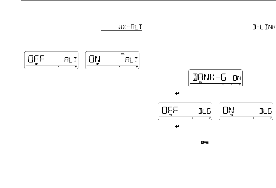
D Weather alert
U.S.A. version only
Turns weather alert function ON and OFF. (p. 000)
(default: OFF)
D Memory bank link function
Sets the memory bank link function ON and OFF (default).
The link function provides continuous bank scan, scanning all
contents in the selected banks during bank scan.
• Bank link setting
q Rotate [DIAL] to select the bank that you want to
change.
w Push [ ](MONI)* to enter bank setting.
e Rotate [DIAL] to select the setting.
r Push [ ](MONI)* to set and return to the BANK selection
screen.
t Rotate [DIAL] to select next bank and repeat steps w to
r, or push [MENU ] to exit scan set mode.
113
12
MENU SCREEN OPERATION
1
2
3
4
5
6
7
8
9
10
11
12
13
14
15
16
17
18
19
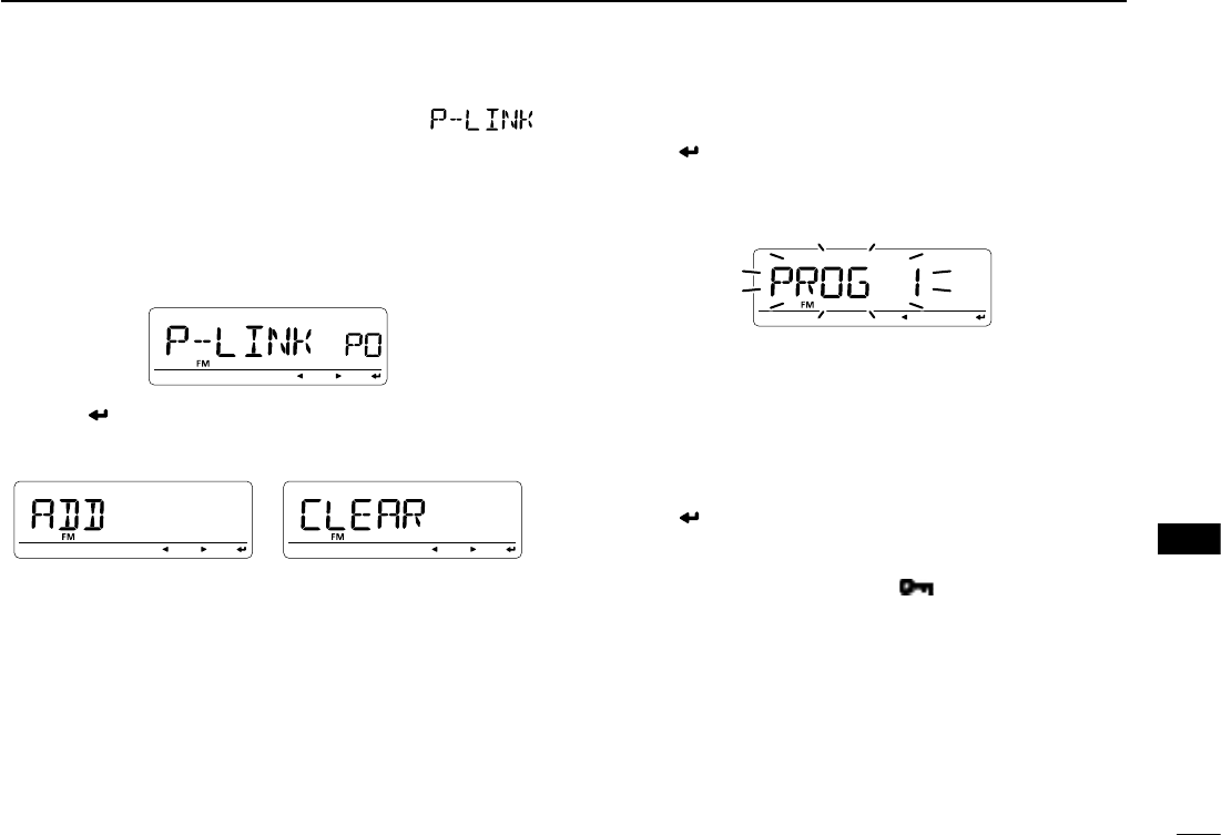
D Program scan link function
Sets the program scan link function ON and OFF (default).
The link function provides continuous program scan in the
selected program scan number during program scan.
• Program scan link setting
q Rotate [DIAL] to select the program scan link channel, P0
to P9, that you want to change.
w Push [ ](MONI)* to enter program scan link setting.
e Rotate [DIAL] to select “ADD” to adding or “CLEAR” to
deleting from programmed scan link setting.
• “LINK” for programmed scan linked number confirmation
(p. 000) and “NAME” for programmed scan link name setting
(p. 000) items also available.
r
Push
[ ](MONI)*
then rotate [DIAL] to select the desired
programmed scan number to be linked (if “ADD” is selected
in step e) or to be deleted from the link (if “CLEAR” is se-
lected in step e).
• “ADD” selection;
The programmed scan numbers, that has not been linked in the
selected program link channel, are only be displayed/selected.
• “CLEAR” selection;
The programmed scan numbers, that has been linked in the se-
lected program link channel, are only be displayed/selected.
• Push [Ω] (CS) to cancel the selection.
t Push [ ](MONI)*
to add/delete the setting.
• Return to the previous indication as step e.
y
Repeat steps e to t to continuing the program scan link
channel setting or push [MENU ] to exit MENU screen
operation.
114
12 MENU SCREEN OPERATION
N SET mode— FUNC items
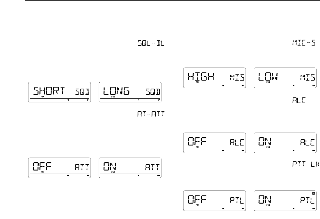
D Squelch delay timer
Selects squelch delay from short and long to prevent re-
peated opening and closing of the squelch during reception
of the same signal.
• SHORT : Short squelch delay. (default)
• LONG : Long squelch delay
D Attenuator
The attenuator prevents distortion of a desired signal by very
strong RF signals near the desired frequency or when very
strong electric fields, such as from a broadcasting station, are
present at your location.
Select the attenuator function ON and OFF (default).
D Mic sens level
Selects the microphone sensitivity from HIGH and LOW to
suit your preference.
(default : USA version; LOW, Other versions; HIGH)
D ALC
Sets the ALC (Automatic Level Control) function ON and OFF
(default).
The ALC function reduces the microphone again automati-
cally when the transmission audio is distorted.
D PTT lock
Turns the PTT lock function ON and OFF.
Transmission with [PTT] is inhibited when ON is selected to
prevent accidental transmission, etc. (default: OFF)
115
12
MENU SCREEN OPERATION
1
2
3
4
5
6
7
8
9
10
11
12
13
14
15
16
17
18
19
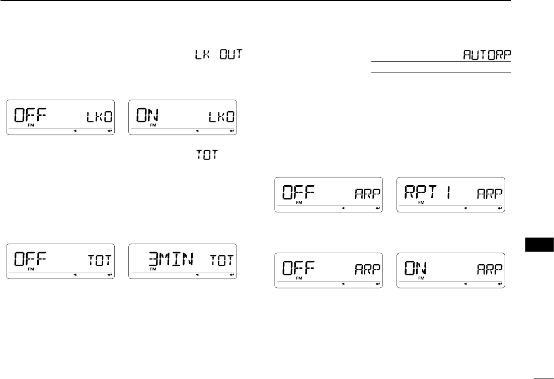
D Busy lockout
Turns the busy lockout function ON and OFF.
This function inhibits transmission while receiving a signal or
when the squelch is open. (default: OFF)
D Time-out timer
To prevent accidental prolonged transmission, etc., the trans-
ceiver has a time-out timer. This function cuts transmission
OFF after 1, 3, 5, 10, 15 or 30 min. of continuous transmis-
sion. This timer can be cancelled.
• OFF : The time-out timer is turned OFF. (default)
• 1 to 30 MIN : The transmission is cut OFF after the set
period elapses.
D Auto repeater
U.S.A. and Korean versions only
The auto repeater function automatically turns ON or OFF
the duplex operation and tone encoder. The offset and re-
peater tone is not changed by the auto repeater function.
Reset these frequencies, if necessary.
U.S.A. version:
• OFF : The auto repeater function is turned OFF.
• RPT1 : Activates for duplex only. (default)
• RPT2 : Activates for duplex and tone.
Korean version:
• OFF : Deactivates the function.
• ON : Activates duplex and tone. (default)
116
12 MENU SCREEN OPERATION
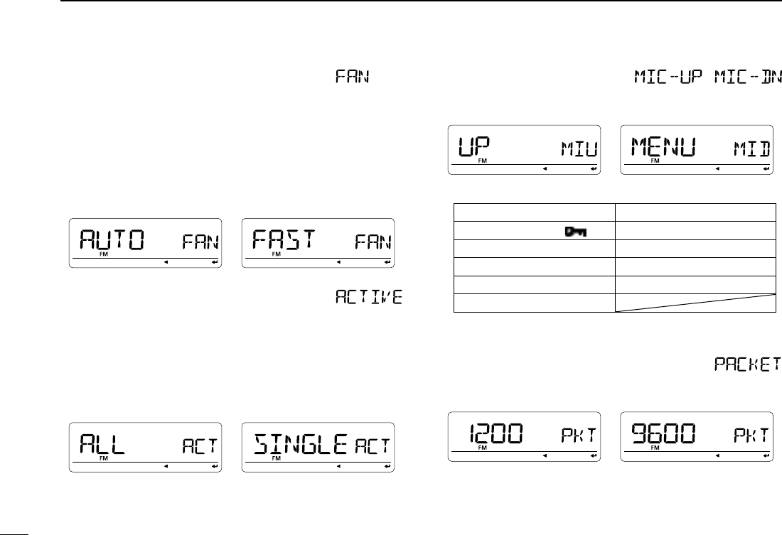
D Fan control
Selects the cooling fan control condition from AUTO, FAST,
MID and SLOW.
• AUTO : The fan rotates during transmit and for 2 min.
after transmission. (default)
• FAST : The fan continuously rotates at fast speed.
• MID : The fan continuously rotates at medium
speed.
• SLOW : The fan continuously rotates at low speed.
D Active band
Allows continuous frequency selection of the operating fre-
quency across all bands.
• SINGLE : A single operating frequency can be selected
within the current band. Push [BAND] for band
selection in this case.
• ALL : The operating frequency can be selected con-
tinuously. (default)
D Mic UP/DN /
Sets the assigning function to the [UP]/[DN] keys on the op-
tional HM-154.
Assignable functions:
UP* (default) DOWN† (default)
MENU (as [MENU ]) V/MHZ (as [VFO/MHz])
BAND (as [BAND MODE]) SMW (as [S.MW MW])
M/CALL (as [M/CALL]) DR (as [DR])
CS (as [CS]) LOW (as [LOW])
MONI (as [MONI])
*Available for “MIC-UP” only; †Available for “MIC-DN” only
D Packet speed
Selects the data transmission speed for packet operation
from 1200 bps (default) and 9600 bps.
117
12
MENU SCREEN OPERATION
1
2
3
4
5
6
7
8
9
10
11
12
13
14
15
16
17
18
19
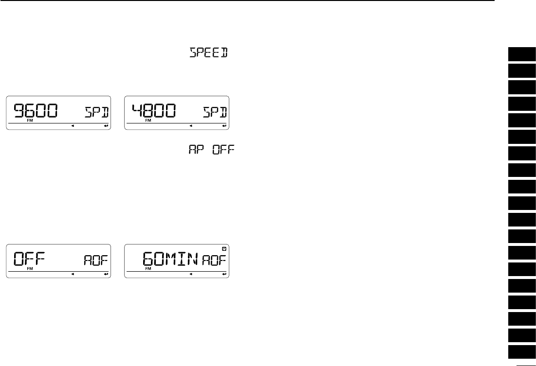
D Data speed
Selects the data communication speed between [DATA]
jack and the connected GPS, PC, etc. from 4800 bps and
9600 bps (default).
D Auto power OFF
The transceiver can be set to automatically turn OFF after a
specified time period with a beep when no key operations are
performed.
30 min., 60 min, 90 min, 120 min and OFF (default) can be
specified. The specified time period is retained even when
the transceiver is turned OFF by the auto power OFF func-
tion. To cancel the function, select “OFF” in this item.
118
12 MENU SCREEN OPERATION
N SET mode— DISP items
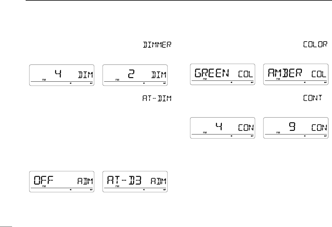
D Display dimmer
Sets backlighting brightness.
The levels 1 (dark) to 4 (bright: default) are available.
D Auto dimmer
Sets backlighting brightness when no operation is performed
for approx. 5 sec.
• OFF : The backlight brightness will not be
changed. (default)
• AUTO–OFF : The backlight will be turned OFF when
no operation is performed for approx.
5 sec.
• AUTO–D1 to D3 : Brightness level 1 to 3 is selected
when no operation is performed for
approx. 5 sec.
D Display color
The display color can be set to amber (default), green or yel-
low.
D LCD contrast
The contrast of the LCD can be selected from 9 levels.
• 1 (Low contrast) to 9 (High contrast) (default: 4)
119
12
MENU SCREEN OPERATION
1
2
3
4
5
6
7
8
9
10
11
12
13
14
15
16
17
18
19
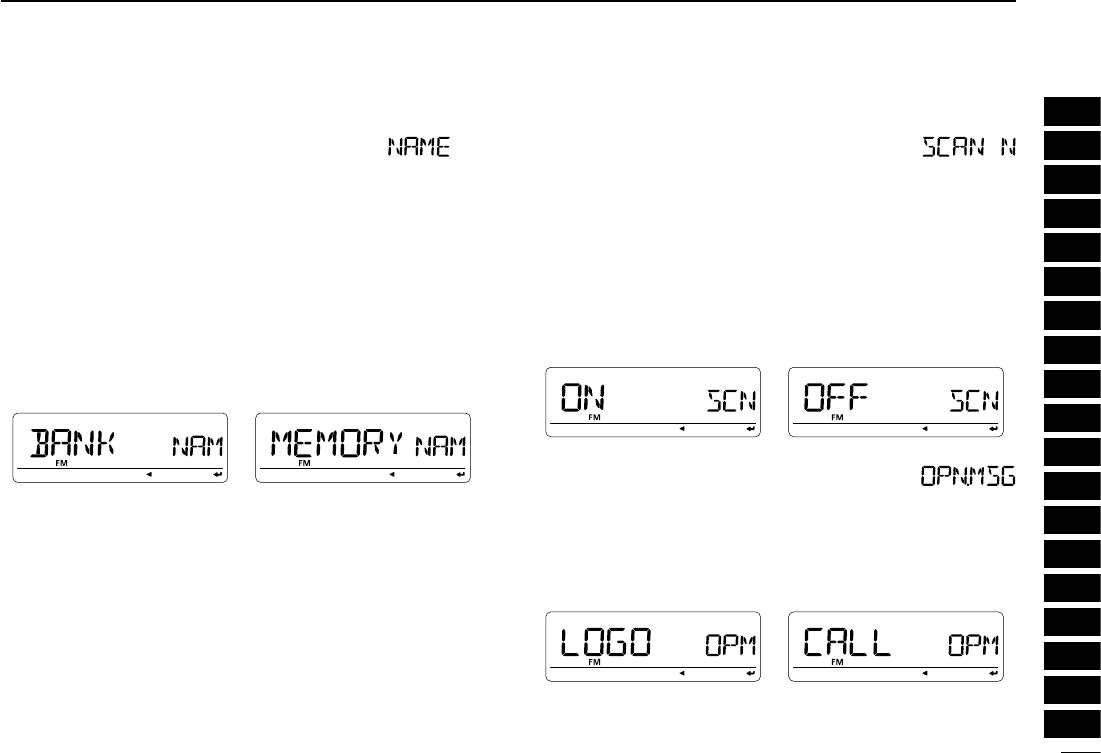
D Name indication type
Selects name indication type from MEMORY, BANK and OFF
during memory mode operation.
• OFF : The programmed frequency is displayed.
• MEMORY : The programmed memory name is dis-
played. However, the programmed fre-
quency is displayed if no memory name is
programmed. (default)
• BANK : The bank name, that the selected memory
channel is assigned to, is displayed. How-
ever, the programmed frequency is dis-
played if no bank name is programmed.
D Scan name
The programmed scan or bank name is displayed during the
scan type selection.
• ON : The programmed scan or bank name is dis-
played. However, the programmed frequency
or the default bank initial is displayed if no scan
or bank name is programmed, respectively. (de-
fault)
• OFF : The programmed frequency or bank initial is dis-
played during selection.
D Opening message
The opening message indication that is displayed at power
ON is selectable from “ICOM” logo, my call sign or skipped.
• LOGO : “ICOM” is displayed at power ON. (default)
• CALL : The set my call sign is displayed at power ON.
• OFF : Opening message indication is skipped.
120
12 MENU SCREEN OPERATION
N Set mode— SOUNDS items
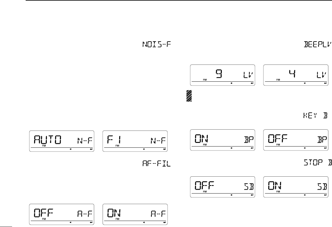
D Noise filter
- Appears only when FM/N or AM/N mode is selected.
The noise filter selects audio signal filter width to reduce high-
pitch noise in analog mode (FM/N, AM/N) operation— clear
voice audio reception is provided. Selects the noise filter from
AUTO, F1–F3.
• AUTO : Selects the suitable audio filter width according
to the received signal strength. When a weak
signal is received, selects a narrow audio filter
width to reduce noise audio. (default)
• F1 : The widest audio filter width.
• F2 : Middle audio filter width.
• F3 : The narrowest audio filter width.
D Audio filter
- Appears only when AM/N mode is selected.
The AF filter suppresses high-pitch tone during AM mode op-
eration.
• OFF : The AF filter is deactivate.
• ON : The AF filter is activate.
D Beep output level
Adjusts the key-touch beep tone level to the desired level
within 9 levels. (default: 9)
The key-touch beep (following item) must be set to ON to
have a beep tone.
D Key-touch beep
Turns the key-touch beep ON or OFF. (default: ON)
D Scan stop beep
Turns the scan stop beep function ON or OFF. (default: OFF)
121
12
MENU SCREEN OPERATION
1
2
3
4
5
6
7
8
9
10
11
12
13
14
15
16
17
18
19
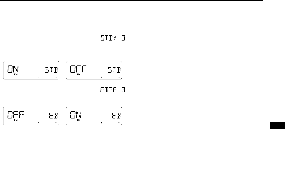
D Standby beep
Turns the beep emission capability ON and OFF when the
communicating station finishes transmitting or the receive
signal disappears during digital mode operation. (default: ON)
D Band edge beep
Turns the beep emission capability ON and OFF when the
frequency is changed over the band edge. (default: ON)
122
12 MENU SCREEN OPERATION
N DV set mode items
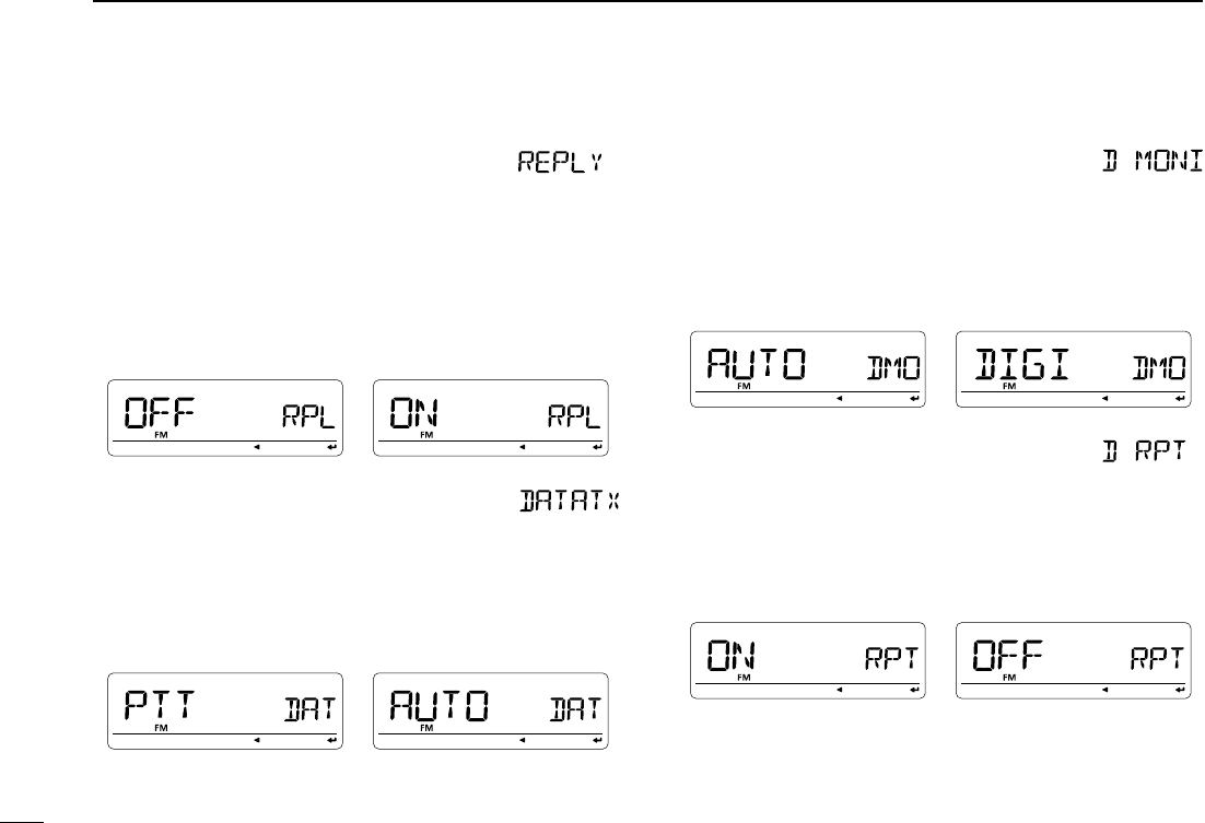
D Auto reply
This function replies to an individual station call even you are
away from the transceiver.
After a manual transmission (pushing [PTT]), the Auto Reply
setting returns to OFF automatically.
• OFF : No reply is performed even if a call is received.
(default)
• ON : Sets the caller's call sign and replies to the call
with the programmed own call sign.
D DV data TX
During low-speed data operation, auto data transmission
function is available. This function transmits when data has
been input from PC via the [DATA] jack.
• PTT : Data from [DATA] transmits when [PTT] is
pushed. (default)
• AUTO : Data from [DATA] transmits automatically.
D Digital monitor
Sets the desired monitoring mode during digital mode opera-
tion from “Auto,” “Digital” and “Analog.”
• AUTO :
The transceiver sets monitoring mode to FM and
DV according to the received signal. (default)
• DIGI : Monitors in DV mode.
• ANALOG : Monitors in FM mode.
D Digital repeater setting
When accessing a digital repeater with a call sign different
than is programmed, the repeater call sign can be stored into
“RPT1” and/or “RPT2” automatically by reading the repeat-
er’s transmission. The previously stored repeater’s call sign
can be recalled when selecting the repeater call sign.
(default: ON)
123
12
MENU SCREEN OPERATION
1
2
3
4
5
6
7
8
9
10
11
12
13
14
15
16
17
18
19
D RX call sign auto write
When an individual station call is received, the calling station
call sign can be automatically set in “UR.” (default: OFF)
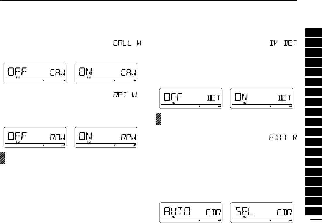
D Repeater call sign auto write
When accessing a repeater with a call sign different than is
programmed, the repeater call sign can be set into “RPT1”
and/or “RPT2” automatically by reading the repeater’s trans-
mission. (default: OFF)
The transceiver sets the received repeater call sign for op-
eration, over-writing the previously set repeater call sign.
D DV auto detect
When a signal other than DV mode is received during DV
mode operation, the transceiver has capability of automatic
FM mode selection.
• OFF : Operating mode is fixed in DV. (default)
• ON : The transceiver automatically selects FM mode
for temporary operation.
The received audio may be distorted with the auto detec-
tion “ON” setting for FM demodulation.
D Call sign edit record
Selects call sign programming when the call sign is edited or
corrected with the pre-programmed call sign.
• OFF : The edited or corrected call sign is over writ-
ten.
• SEL : The edited or corrected call sign is pro-
grammed into the selected call sign memory.
• AUTO : The edited or corrected call sign is pro-
grammed into a blank channel automatically.
(default)
124
12 MENU SCREEN OPERATION
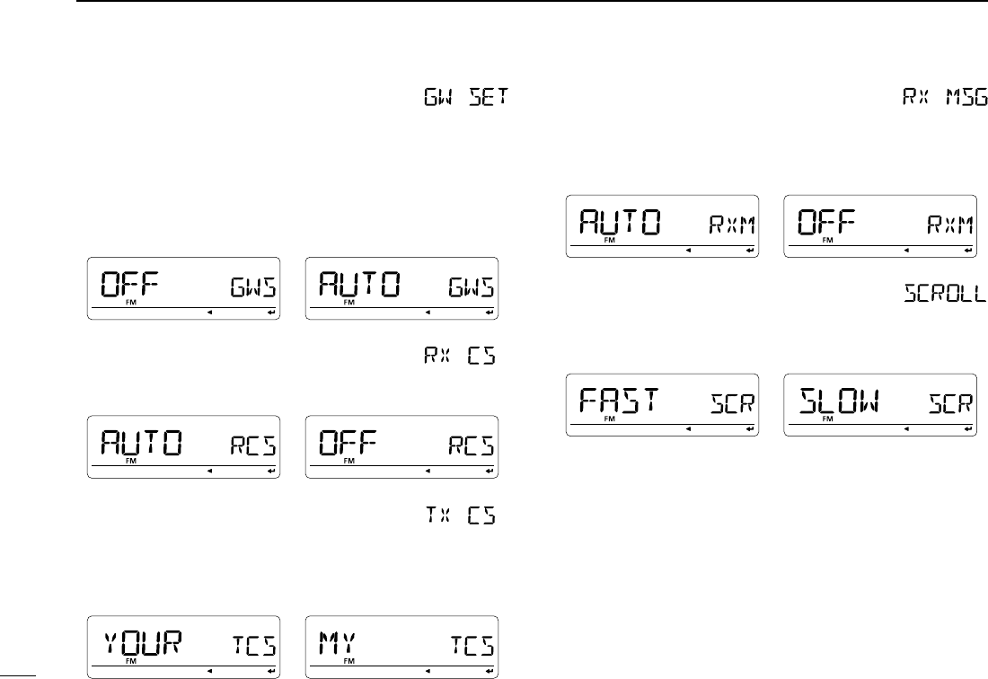
D Auto gateway setting
The auto gateway setting simplifies the gateway repeater set-
ting for individual station call in DR mode operation.
• OFF : The gateway repeater callsign should be set
by manually. (default)
• AUTO : The gateway repeater callsign, that is in the
same repeater group of the selected uplink re-
peater, is automatically set.
D RX call sign display
When a call is received, the calling station call sign can be in-
dicated automatically. (default: AUTO)
D TX call sign display
Selects call sign display function from YOUR, MY and OFF.
When this setting is set to YOUR or MY, the transceiver au-
tomatically indicates the set station or your own call sign dur-
ing digital mode transmission. (default: YOUR)
D RX message display
Sets auto received message display function from AUTO and
OFF. When this setting is set to AUTO, the transceiver auto-
matically displays and scrolls the received message.
(default: AUTO)
D Scroll speed
Set the displayed message, call sign, etc. scrolling speed.
• FAST : Scroll speed is set to fast. (default)
• SLOW : Scroll speed is set to slow.
125
12
MENU SCREEN OPERATION
1
2
3
4
5
6
7
8
9
10
11
12
13
14
15
16
17
18
19
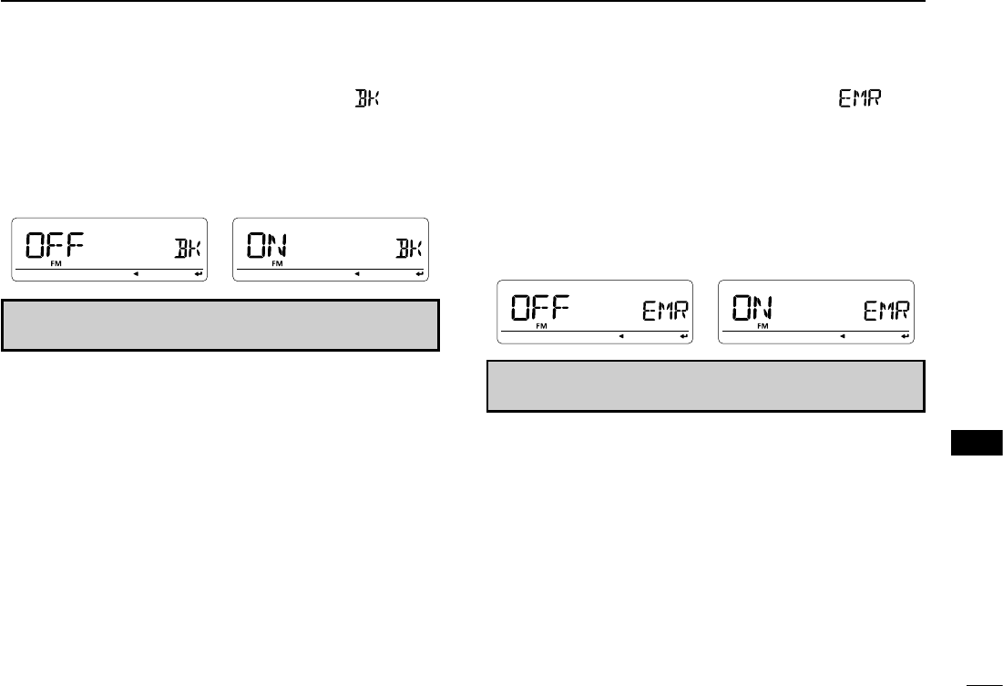
D Break-in function
The break-in function allows you to break into a conversation
where the two original stations are communicating with call
sign squelch enabled.
• OFF : The break-in function is set to OFF. (default)
• ON : The break-in function is set to ON.
NOTE: The break-in function is turned OFF automatically
when turning transceiver’s power OFF
D EMR function
The EMR communication mode is available for digital mode
operation. In the EMR communication mode, no call sign set-
ting is necessary. When an EMR communication mode sig-
nal is received, the audio (voice) will be heard at the specified
level even the volume setting level is set to minimum level, or
digital call sign/digital code squelch is in use.
• OFF : The EMR function is set to OFF. (default)
• ON : The EMR function is set to ON.
NOTE: The EMR communication function is turned OFF
automatically when turning transceiver’s power OFF
N GPS mode items
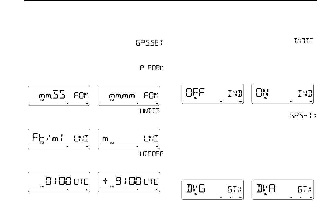
D GPS set
The following individual settings are available in GPS set. Set
them to suit your GPS operation.
- Position format
Selects the displaying position format from “mm.mm” (default)
and “mm.SS.”
- Unit selection
Selects display units for distance and elevation from “m” or
“ft/ml.” (default : U.S.A. version; ft/ml, Other versions; m)
- UTC offset setting
Sets time difference from UTC (Universal Time Coordinated)
within –12:00 to +12:00 range in 5 min. steps. (default: 0:00)
- INDIC
Sets the GPS indicator ON and OFF. (default : ON)
• OFF : “GPS” indicator does not appear.
• ON : “GPS” indicator appears on the display when a
GPS receiver is connected and a valid position
data is received; blinks when an invalid data is
received.
D GPS transmission
Sets the transmission of data from a connected GPS receiver
ON and OFF.
When the position information is received from a connected
GPS receiver and the GPS Auto TX Timer setting (p. 000) is
set to a specific time, the transceiver automatically transmits
the current position and message at the set interval.
• OFF : Transmitting position data is disabled. (default)
• DVG : Transmitting position data in GPS mode.
• DVA : Transmitting position data in GPS-A mode.
126
12 MENU SCREEN OPERATION
127
12
MENU SCREEN OPERATION
1
2
3
4
5
6
7
8
9
10
11
12
13
14
15
16
17
18
19
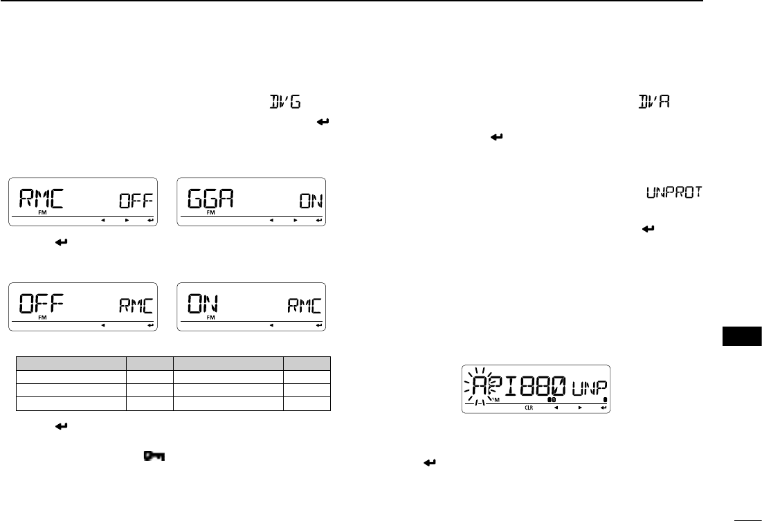
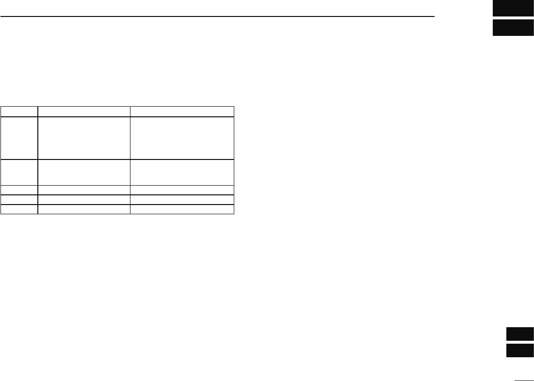
Sentence formatter setting
q Select “DVG” in GPS transmission item, then push [ ]
(MONI) to enter the sentence formatter selection.
w Rotate [DIAL] to select the desired sentence formatter.
• RMC, GGA, GLL, GSA, VTG and GSV are selectable.
e Push [ ] (MONI) to enter the desired sentence formatter
selection.
r Rotate [DIAL] to select ON/OFF.
• Default setting for sentence formatter
Sentence formatter Default Sentence formatter Default
RMC OFF GSA OFF
GGA ON VTG OFF
GLL OFF GSV OFF
t Push [ ] (MONI) to store the selection.
y Rotate [DIAL] to select next sentence and repeat steps w
to t, or push [MENU ] to return to frequency indica-
tion.
•
Only four sentence formatters can be activated at the same time.
GPS-A Set mode
Enter GPS-A operation set mode by selecting “DVA” in GPS
TX mode, then push [] (MONI). This set mode is available
to set unproto address, data extension, time stamp, GPS-A
symbol and comment.
- Unproto address
56 characters address can be entered for unproto address.
q Rotate [DIAL] to select “UNPROT” then push [] (MONI)
to enter the unproto address edit mode.
w Rotate [DIAL] to select the desired character.
• “API880,DSTAR” is preset as the default.
• The first character blinks.
• Push [≈] (LOW) to move the cursor right; push [Ω] (CS) to
move the cursor left.
• Push [CLR] (DR) to erase the selected character, or push and
hold [CLR] (DR) for 1 sec. to erase all characters following the
cursor.
e Repeat step w until the desired unproto address is pro-
grammed.
r Push [] (MONI) to program the unproto address and re-
turn to the unproto address edit mode.
t Push [] (CS) to return to GPS-A set mode item indica-
tion.
128
12 MENU SCREEN OPERATION
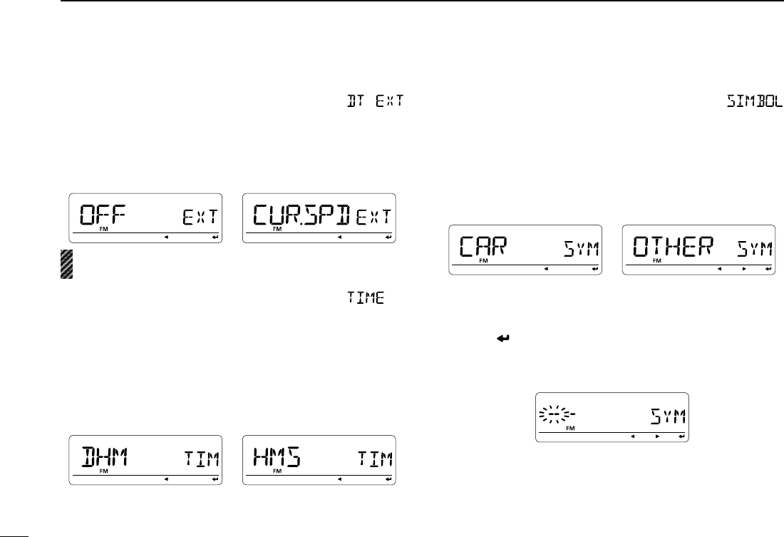
- DATA extension
Sets the data extension capability to “CUR.SPD” or OFF (de-
fault).
The transceiver’s course and speed information is addition-
ally transmitted with position data when “CUR.SPD” is se-
lected.
NOTE: When “CUR.SPD” is selected, number of character
for “COMMENT” is limited to 36-character.
- Time stamp
Selects transmitting time stamp type from DHM, HMS and
OFF. This function can be transmitted UTC (Universal Time
Coordinated) time only.
•
OFF : No time stamp is transmitted. (default)
•
DHM : Time stamp in the format of Day, Hour and
Minute is transmitted.
•
HMS : Time stamp in the format of Hour, Minute and
Second is transmitted.
- GPS-A symbol
Selects the desired GPS-A symbol.
Available symbols: AMBU (Ambulance), BUS (Bus), FIRE
(Fire Truck), BICYCL (Bicycle), YACHT (Yacht), HELI (He-
licopter), AIRCRA (Small Aircraft), SHIP (Power Boat), CAR
(Car: default), MCYCLE (Motorcycle), BALLOO (Balloon),
JEEP (Jeep), RV (Recreational Vehicle), TRUCK (Truck),
VAN (Van) and OTHER (Other).
If “OTHER” is selected, set the desired symbol code as fol-
lows;
q Push [] (MONI) to begin programming.
• 1st character blinks.
• “--” blinks at the 1st character and “--” appears at the 2nd char-
acter if no symbol is programmed previously.
w Rotate [DIAL] to select the 1st character from “\” and “/.”
e Push [] (LOW) to select the 2nd digit.
r Rotate [DIAL] to select the 2nd digit character.
• A–Z (capital letters), 0–9, ", #, $, %, &, ', <, >, , +, ,, −, ., /, :, =,
?, @ and space are available for 2nd character.
t Push [ ] (MONI) to program the symbol code, then exit
programming.
y Push [] (CS) to return to GPS-A set mode item indica-
tion.
When “OTHER” is selected, check the symbol codes of
APRS® and set it correctly.
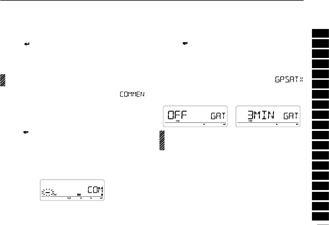
- Comment
Program up to a 43-character* comment. The programmed
comment is transmitted with the GPS position data.
* 36-character comment can only be programmed when “CUR.SPD”
is selected in data extension.
q Push [ ] (MONI) to enter programming.
w Rotate [DIAL] to select the desired character.
• The selected character blinks.
• Push [≈] (LOW) to move the cursor right; push [Ω] (CS) to
move the cursor left.
• Push [CLR] (DR) to erase the selected character, or push and
hold [CLR] (DR) for 1 sec. to erase the characters following the
cursor.
e Repeat step w until the desired comment is pro-
grammed.
r Push [] (MONI) to program the comment and exit com-
ment programming.
t Push [] (CS) to return to GPS-A set mode item indica-
tion.
D GPS auto transmission
Selects the desired interval for automatic position transmis-
sion function from OFF (default), 5, 10, 30 second, 1, 3, 5, 10
and 30 minutes.
NOTE: When four sentence formatter are activated at the
same time (“GPS SENTENCE” on pgs. 000, 000), “5SEC”
can not be selected.
129
12
MENU SCREEN OPERATION
1
2
3
4
5
6
7
8
9
10
11
12
13
14
15
16
17
18
19
a
18
SPECIFICATIONS AND OPTIONS
1
2
3
4
5
6
7
8
9
10
11
12
13
14
15
16
17
18
19
N Specifications
D GENERAL
• Frequency coverage : (unit: MHz)
Version TX RX
U.S.A. 144–148, 430–450 118–173.995,
230–549.995,
810–823.990,
849–868.990,
894–999.990
CHN
EXP
136–173.995*1,
400–469.995*2
118–173.995,
230–549.995,
810–999.990
KOR 144–146, 430–440 144–146, 430–440
AUS 144–148, 430–440 144–148, 430–440
TPE 144–146, 430–432 144–146, 430–432
*
1Guaranteed 144–148 MHz only, *2Guaranteed 430–440 MHz only
• Type of emission : FM, AM (Receive only), DV
• Number of memory channels : 1052 (incl. 50 scan edges and 2 calls)
• Frequency resolution : 5‡, 6.25‡, 8.33‡, 10, 12.5, 15‡, 20, 25,
30, 50, 100, 200 kHz
• Operating temperature range : –10°C to +60°C; +14˚F to +140˚F
• Frequency stability :-±2.5 ppm (–10°C to +60°C)
• Power supply requirement : 13.8 V DC ±15%
• Current drain (at 13.8 V DC: approx.):
Transmit at 50 W VHF: 11.5 A*
UHF: 12.5 A*
* 8.0 A (at 25 W) only for the TPE version
Receive standby 0.9 A
(simultaneous receive) max. audio 1.2 A
• Antenna connector : SO-239 (50 Ω)
• Dimensions (proj. not included) : 150(W) × 40(H) × 199.2(D) mm
529⁄32(W)×19⁄16(H)×727⁄32(D) in
• Weight (approx.) : 1.3 kg; 2 lb 14 oz (not incl. cable)
D TRANSMITTER
• Modulation system :
FM
Variable reactance frequency modulation
DV (DIgital) GMSK reactance frequency modulation
• Output power : 50/15/5 W* (approx.)
*25/15/5 W only for the TPE version.
• Max. frequency deviation : ±5.0 kHz (wide)
±2.5 kHz (narrow)
• Spurious emissions : Less than –60 dB
• Microphone connector : 8-pin modular (600 Ω)
D RECEIVER
• Receive system : Double conversion superheterodyne
• Intermediate frequencies : 1st: 46.35 MHz, 2nd: 450 kHz
• Sensitivity (amateur bands only):
FM
(12 dB SINAD) Less than 0.18 μV
DV (BER 1%) Less than 0.35 μV
• Squelch sensitivity† (threshold) : Less than 0.13 μV
• Selectivity† (typical) :
Wide More than 10 kHz/6 dB
Less than 30 kHz/60 dB
Narrow More than 6 kHz/6 dB
Less than 20 kHz/60 dB
DV More than 50 dB
• Spurious and image rejection† : More than 60 dB
•
AF output power
†
(at 13.8 V DC)
: More than 2.0 W at 10% distortion with an 8 Ω
load
• Ext. speaker connectors : 3-conductor 3.5 (d) mm (1⁄8″)/8 Ω
†Guaranteed 144–146 or 144–148 MHz and 430–440 or 440–450 MHz ranges only.
All stated specifications are subject to change without notice or obligation.
‡Selectable depending on the operating frequency band.

b
18 SPECIFICATIONS AND OPTIONS
• Sensitivity (for RX bands— FM/AM; for your reference only):
Frequency range FM (μV) AM (μV)
118–136.995 MHz 0.32 1
137–173.995 MHz 0.32 1
230–259.995 MHz 1.8 5.6
260–299.995 MHz 0.56 1.8
300–349.995 MHz 0.56 1.8
350–399.995 MHz 0.56 1.8
400–499.995 MHz 0.32 1
500–549.995 MHz 0.56 1.8
810–879.990 MHz 0.71 N/A
880–999.990 MHz 0.71 N/A

c
18
SPECIFICATIONS AND OPTIONS
1
2
3
4
5
6
7
8
9
10
11
12
13
14
15
16
17
18
19
N Options
CS-80/880 CLONING SOFTWARE (free download)
Use this software to program settings such as memory channels and
set mode contents quickly and easily via PC’s RS-232C terminal
using the data communication cable, OPC-1529R. USB type cloning
cable, OPC-478UC, also available.
HM-133 REMOTE-CONTROL MICROPHONE
Remote control microphone with key backlight. Same as that sup-
plied with the transceiver.
HM-154 HAND MICROPHONE
OPC-347/1132 DC POWER CABLES
OPC-347: 7.0 m
OPC-1132: 3.0 m Same as that supplied with the transceiver.
OPC-440 MIC EXTENSION CABLE
5.0 m
OPC-441 SPEAKER EXTENSION CABLE
5.0 m
OPC-474 CLONING CABLE
Used for data cloning between transceivers.
OPC-478UC CLONING CABLE
Used for data cloning between transceiver and PC with CS-80/880.
OPC-1529R DATA COMMUNICATION CABLE
Allows low-speed data communication in DV mode and data cloning
operation with CS-80/880
SP-10 EXTERNAL SPEAKERS
For all-round mobile operation. Cable length: 1.5 m
MB-120 MOUNTING BASE
Mounts the remote controller on to variety of place in vihicle. Remote
controller bracket is required for mounting.

A-6728D-1EX
Printed in Japan
© 2009 Icom Inc.
Printed on recycled paper with soy ink. 1-1-32 Kamiminami, Hirano-ku, Osaka 547-0003, Japan