ICOM orporated 316700 VHF/UHF Amateur Transceiver User Manual ID 880H Draft
ICOM Incorporated VHF/UHF Amateur Transceiver ID 880H Draft
Contents
- 1. User Manual 1
- 2. User Manual 2
- 3. User Manual 3
- 4. User Manual 4
User Manual 1
This device complies with Part 15 of the FCC Rules. Operation is
subject to the following two conditions: (1) this device may not cause
harmful interference, and (2) this device must accept any interference
received, including interference that may cause undesired operation.
WARNING: MODIFICATION OF THIS DEVICE TO RECEIVE CEL-
LULAR RADIOTELEPHONE SERVICE SIGNALS IS PROHIBITED
UNDER FCC RULES AND FEDERAL LAW.
INSTRUCTION MANUAL
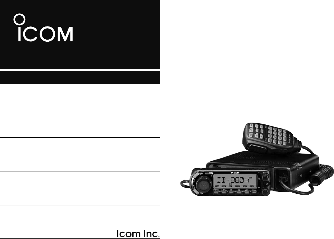
ID-880H
VHF/UHF DIGITAL TRANSCEIVER

i
FOREWORD
Thank you for purchasing this fine Icom product. The ID-880H
VHF/UHF DIGITAL TRANSCEIVER is designed and built with Icom’
s state of the art technology and craftsmanship. With proper
care, this product should provide you with years of trouble-free
operation.
We want to take a couple of moments of your time to thank
you for making your ID-880H your radio of choice, and hope
you agree with Icom’s philosophy of “technology first.” Many
hours of research and development went into the design of
your ID-880H.
EXPLICIT DEFINITIONS
FEATURES
M DV mode (Digital voice + Low-speed data
communication) operation ready
– Text message and call sign exchange
– Transmitting position data with a third-party
GPS receiver
M DR (D-STAR Repeater) mode and repeater
list allow you to operate D-STAR repeater
simply
M Switchable VHF and UHF transceiver
M 50 W*—high transmit output power
* VHF band; 50 W for UHF band
M Detachable controller for flexible installa-
tion
MLarge tuning dial and band switch button
IMPORTANT
READ ALL INSTRUCTIONS carefully and completely
before using the transceiver.
SAVE THIS INSTRUCTION MANUAL— This
instruction manual contains important operating instructions
for the ID-880H.
WORD DEFINITION
R WARNING!
CAUTION
NOTE
Personal injury, fire hazard or electric shock
may occur.
Equipment damage may occur.
Recommended for optimum use. No risk of
personal injury, fire or electric shock.

ii
RWARNING RF EXPOSURE! This device emits Radio
Frequency (RF) energy. Extreme caution should be observed when
operating this device. If you have any questions regarding RF ex-
posure and safety standards please refer to the Federal Communi-
cations Commission Office of Engineering and Technology’s report
on Evaluating Compliance with FCC Guidelines for Human Radio
frequency Electromagnetic Fields (OET Bulletin 65).
RWARNING! NEVER connect the transceiver to an AC out-
let. This may pose a fire hazard or result in an electric shock.
RWARNING! NEVER operate the transceiver while driving
a vehicle. Safe driving requires your full attention—anything less may
result in an accident.
NEVER connect the transceiver to a power source of more than
16 V DC. This will damage the transceiver.
NEVER connect the transceiver to a power source using reverse
polarity. This will damage the transceiver.
NEVER cut the DC power cable between the DC plug and fuse
holder. If an incorrect connection is made after cutting, the trans-
ceiver may be damaged.
NEVER expose the transceiver to rain, snow or any liquids. The
transceiver may be damaged.
NEVER operate or touch the transceiver with wet hands. This may
result in an electric shock or damage the transceiver.
NEVER place the transceiver where normal operation of the ve-
hicle may be hindered or where it could cause bodily injury.
NEVER let objects impede the operation of the cooling fan on the
rear panel.
DO NOT
push the PTT when not actually desiring to transmit.
DO NOT allow children to play with any radio equipment contain-
ing a transmitter.
During mobile operation, DO NOT operate the transceiver without
running the vehicle’s engine. When the transceiver’s power is ON and
your vehicle’s engine is OFF, the vehicle’s battery will soon become
exhausted.
AVOID using or placing the transceiver in direct sunlight or in
areas with temperatures below –10°C or above +60°C.
BE CAREFUL! The transceiver will become hot when operat-
ing it continuously for long periods.
AVOID setting the transceiver in a place without adequate ventila-
tion. Heat dissipation may be affected, and the transceiver may be
damaged.
AVOID the use of chemical agents such as benzine or alcohol
when cleaning, as they can damage the transceiver’s surfaces.
USE Icom microphones only (supplied or optional). Other manufac-
turer’s microphones have different pin assignments and may damage
the transceiver if attached.
For USA only
CAUTION: Changes or modifications to this device, not
expressly approved by Icom Inc., could void your authority to
operate this device under FCC regulations.
PRECAUTIONS
iii
FCC INFORMATION
• FOR CLASS B UNINTENTIONAL RADIATORS:
This equipment has been tested and found to comply with the
limits for a Class B digital device, pursuant to part 15 of the
FCC Rules. These limits are designed to provide reasonable
protection against harmful interference in a residential instal-
lation. This equipment generates, uses and can radiate radio
frequency energy and, if not installed and used in accordance
with the instructions, may cause harmful interference to radio
communications. However, there is no guarantee that inter-
ference will not occur in a particular installation. If this equip-
ment does cause harmful interference to radio or television
reception, which can be determined by turning the equipment
off and on, the user is encouraged to try to correct the inter-
ference by one or more of the following measures:
• Reorient or relocate the receiving antenna.
• Increase the separation between the equipment and re-
ceiver.
• Connect the equipment into an outlet on a circuit different
from that to which the receiver is connected.
• Consult the dealer or an experienced radio/TV technician
for help.
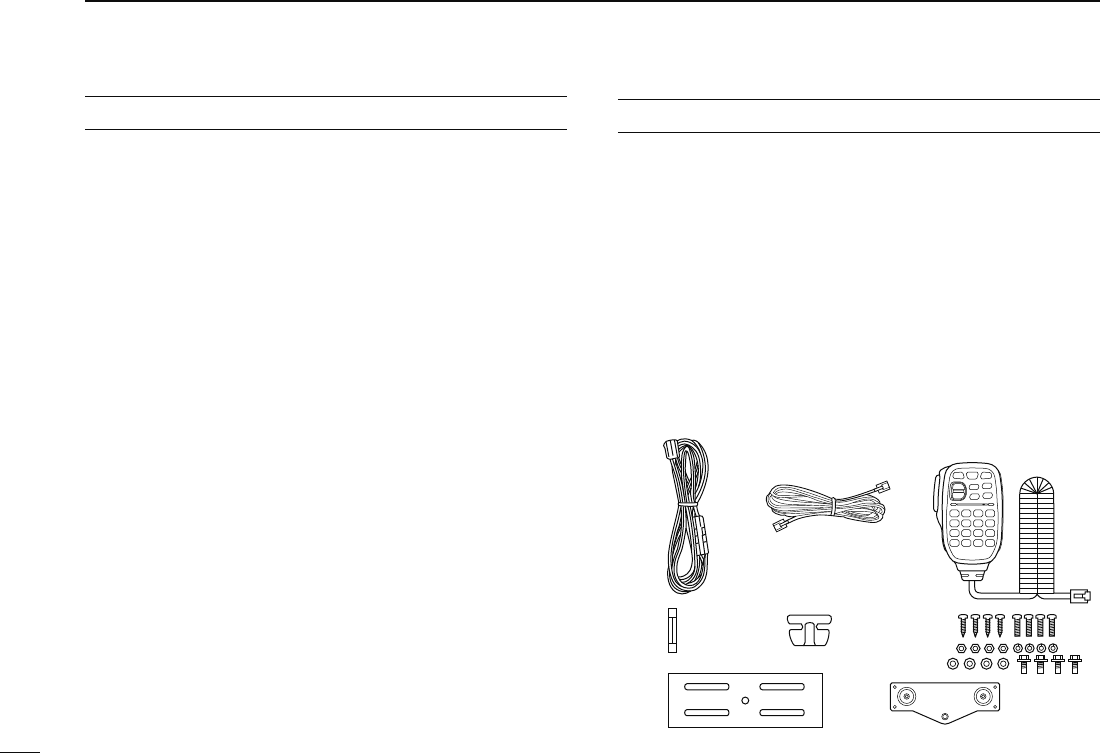
The following accessories are supplied with the transceiver.
q DC power cable (3 m) ......................................................1
w Separation cable (3.4 m†; 11.2 ft†) ...................................1
e Microphone (HM-133)* .....................................................1
r Fuse (20 A) ......................................................................1
t Microphone hanger ...........................................................1
y Mounting screws, nuts and washers .......................... 1 set
u Mobile mounting bracket ..................................................1
i Remote controller bracket .................................................1
*HM-154 HAND MICROPHONE may be supplied with some versions.
†Approx.
q
tr
iu
y
we
SUPPLIED ACCESSORIES
Icom, Icom Inc. and the Icom logo are registered trademarks of Icom
Incorporated (Japan) in the United States, the United Kingdom, Ger-
many, France, Spain, Russia and/or other countries.
Microsoft, Windows and Windows Vista are either registered trade-
marks or trademarks of Microsoft Corporation in the United States
and/or other countries.
I
QUICK REFERENCE GUIDE
N Installation
D Precaution— magnets
RCAUTION
Magnets are used for the controller’s attachment to the main
unit.
NEVER attach the controller on the main unit’s top cover,
particularly around the internal speaker grill. It may cause the
contents of the CPU and memory device could be deleted.
NEVER put the controller near a clock, television set (CRT
type), magnetic compass and any magnetic/IC cards, credit
cards, etc. It may cause the product to malfunction, and the
content of the magnetic card could be deleted.
Please note that the controller may drop off when a high im-
pact or vibration is applied.
D Installation methods
• Single body installation
Transceiver
• The supplied mounting bracket can be used for the main
unit installation.
II
QUICK REFERENCE GUIDE
1
2
3
4
5
6
7
8
9
10
11
12
13
14
15
16
17
18
19
• Remote installation
Main unit
Controller
• The supplied remote controller bracket and separation cable
can be used for installation.
• Optional OPC-440 MICROPHONE CABLE (5.0 m; 16.4 ft) is
available to extend the microphone cable.
• Optional OPC-441 SPEAKER CABLE (5.0 m; 16.4 ft) is avail-
able to extend the speaker cable.
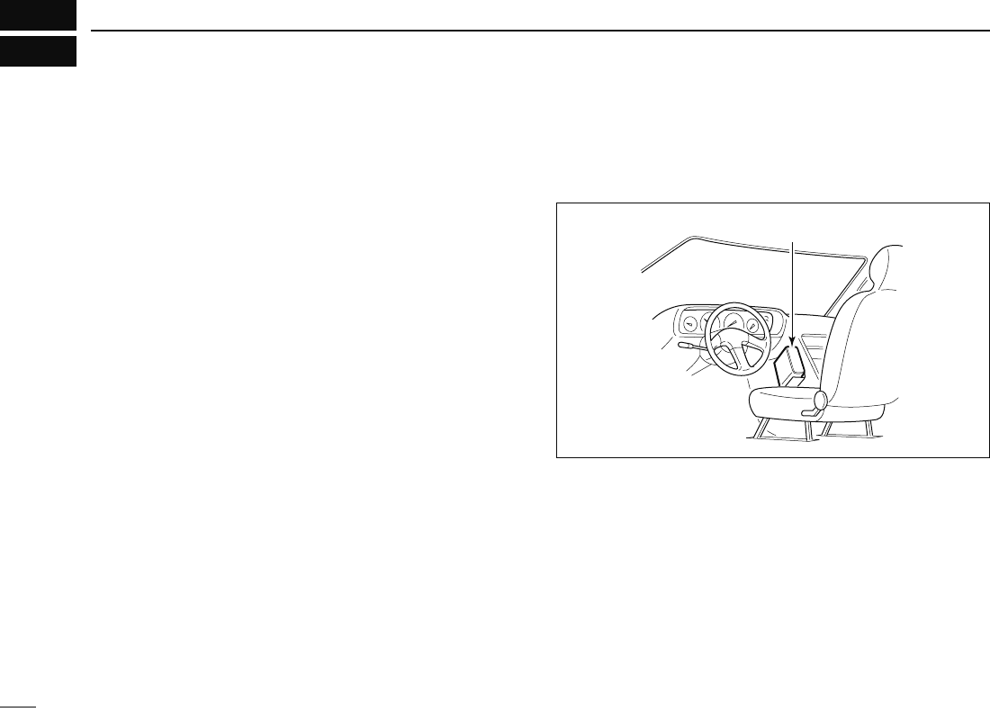
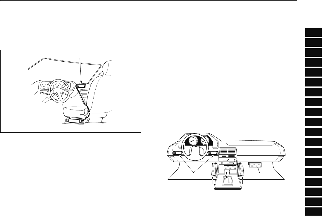
D Location
Select a location which can support the weight of the trans-
ceiver and does not interfere with driving. We recommend the
locations shown in the diagram below.
NEVER place the transceiver or remote controller where
normal operation of the vehicle may be hindered or where it
could cause bodily injury.
NEVER place the transceiver or remote controller where air
bag deployment may be obstructed.
DO NOT place the transceiver or remote controller where hot
or cold air blows directly onto it.
AVOID placing the transceiver or remote controller in direct
sunlight.
Controller
Main unit
Main unit
Main unit
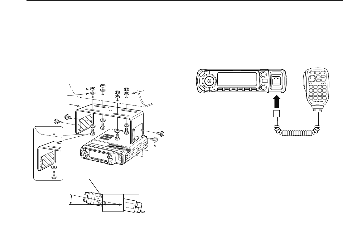
D Using the mounting bracket
q Drill 4 holes where the mounting bracket is to be installed.
• Approx. 5.5–6 mm (1⁄4″) when using nuts; approx. 2–3 mm (1⁄8″)
when using self-tapping screws.
w Insert the supplied screws, nuts and washers through the
mounting bracket and tighten.
e Adjust the angle for your suitable position.
Nut
Spring washer
When using
self-tapping
screws
Flat washer
Mounting nut
Mounting
bracket
25°
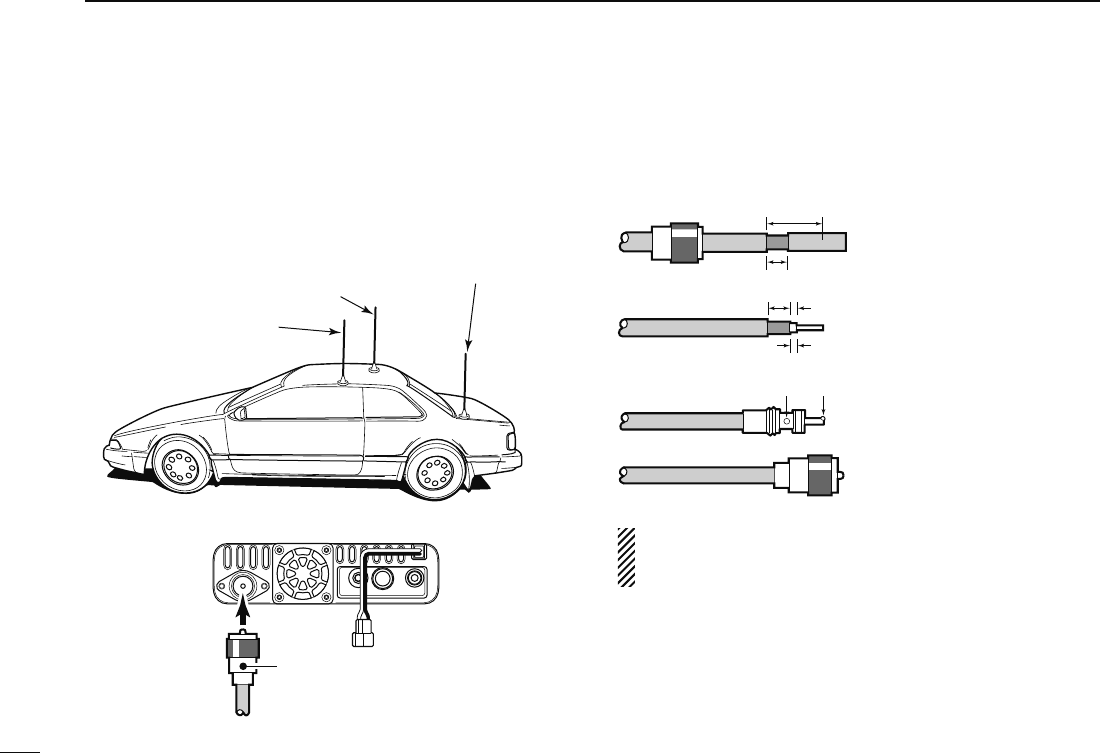
D Microphone connection
A microphone connector is available on the main unit front
panel. Connect the supplied microphone connector as illus-
trated below.
Transceiver Microphone
III
QUICK REFERENCE GUIDE
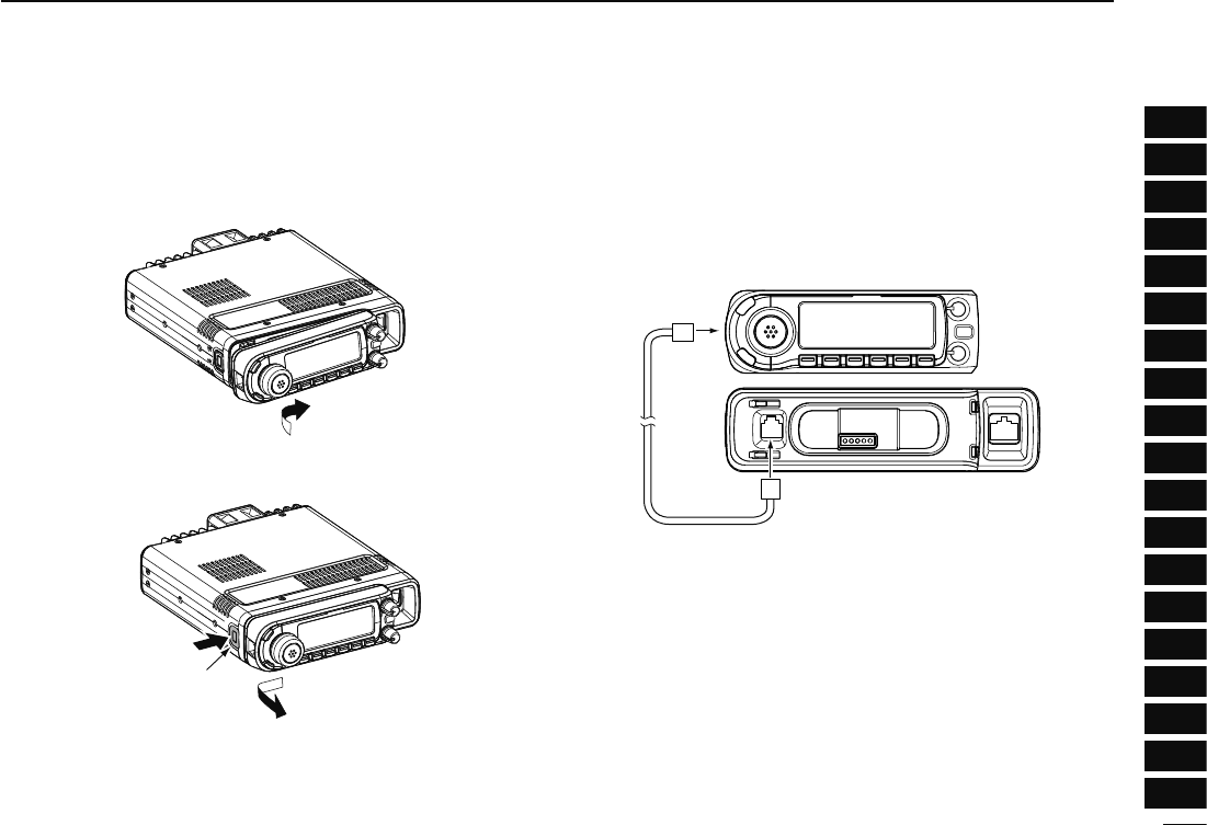
D Controller’s attachment/detachment
You can attach or detach the controller to/from the main unit
as below.
• Attach the controller
• Detach the controller
q
w
e
Release latch
D Separation cable connection
Using the supplied separation cable (3.4 m; 11.2 ft), the con-
troller can be separated from the main unit, doubling as a
remote controller.
Connect the controller and the main unit using with the sup-
plied separation cable as follows.
Controller
Main unit
IV
QUICK REFERENCE GUIDE
1
2
3
4
5
6
7
8
9
10
11
12
13
14
15
16
17
18
19
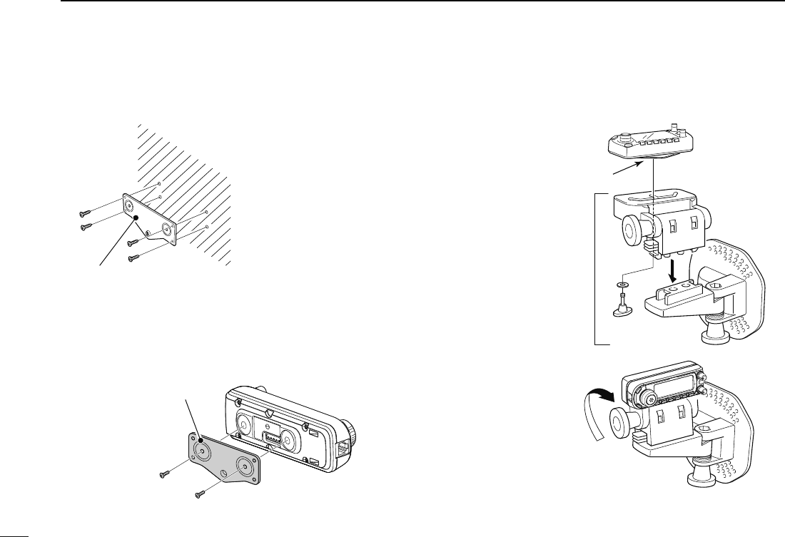
D Remote installation
The supplied remote controller bracket is used for remote in-
stallation.
These screws
are not supplied.
Remote controller bracket
• Attach the remote controller
bracket onto a flat surface
using with 4 self-tapping
screws (2.6 mm(d)), or double-
sticky tape, etc., as at left,
then attach remote controller
to the bracket.
When installing into your vehicle
q Remove two screws and magnets from the remote control-
ler.
w Attach the supplied remote controller bracket as below.
Remote controller
bracket
Remote
controller
e Attach the remote controller on to the optional MB-65 as
below.
Remote controller bracket
Optional
MB-120
Adjust the viewing angle
for maximum visibility of
the function display.
V
QUICK REFERENCE GUIDE
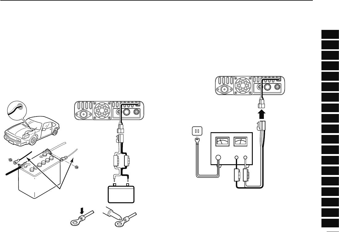
D Battery connection
± RWARNING NEVER remove the fuse holders from the
DC power cable.
±NEVER connect the transceiver directly to a 24 V battery.
± DO NOT use the cigarette lighter socket for power connec-
tions. (See p. 10 for details)
Use a rubber grommet when passing the DC power cable
through a metal plate to prevent a short circuit.
• CONNECTING TO A DC POWER SOURCE
ID-880H
Fuses
20 A
black
red+_
12 V
Grommet
NOTE:
Use terminals for the
cable connections.
R
WARNING
!
NEVER
remove the
fuse holders.
Crimp Solder
12 V
battery Supplied
DC power cable
+ red
_ black
D DC power supply connection
Use a 13.8 V DC power supply with at least 13 A capacity.
Make sure the ground terminal of the DC power supply is
grounded.
• CONNECTING TO A DC POWER SUPPLY
DC power
supply 13.8 V
to an
AC
outlet
Fuses
20 A
ID-880H
+ red
_ black
+_
See p. 134 for fuse replacement.
VI
QUICK REFERENCE GUIDE
1
2
3
4
5
6
7
8
9
10
11
12
13
14
15
16
17
18
19
VII
QUICK REFERENCE GUIDE
D Antenna installation
• Antenna location
To obtain maximum performance from the transceiver, se-
lect a high-quality antenna and mount it in a good location. It
is not necessary to use radials on a magnetic mount (“mag
mount”) antenna.
Roof-mount antenna
(Drill a hole or use a magnetic mount.)
Gutter-mount antenna
Trunk-mount
antenna
To antenna
• Antenna connector
The antenna uses a PL-259 connector.
• PL-259 CONNECTOR
30 mm
10 mm (soft solder)
10 mm
1–2 mm
solder solder
Soft
solder
Coupling ring
q- Slide the coupling ring
down. Strip the cable
jacket and tin.
w- Strip the cable as shown
at left. Soft solder the cen-
ter conductor.
e- Slide the connector body
on and solder it.
r- Screw the coupling ring
onto the connector body.
(10 mm ≅ 3⁄8 in)
NOTE: There are many publications covering proper
antennas and their installation. Check with your local
dealer for more information and recommendations.
VIII
QUICK REFERENCE GUIDE
1
2
3
4
5
6
7
8
9
10
11
12
13
14
15
16
17
18
19
N Your first contact
Now that you have your ID-880H installed in your car or
shack, you are probably anxious to get on the air. We would
like to take you through a few basic operation steps to make
your first time “On The Air” an enjoyable experience.
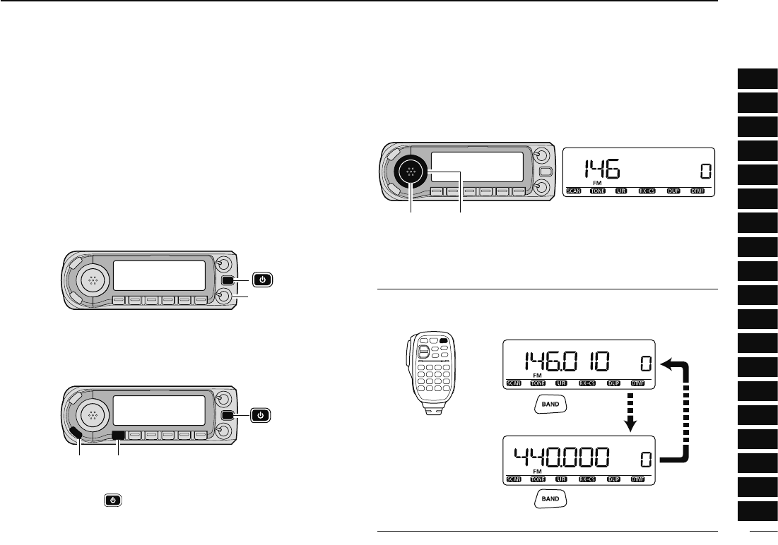
1. Turning ON the transceiver
Before powering up your ID-880H, you may want to make
sure the audio volume and squelch level controls are set in
9–10 o’clock positions.
[SQL]
Although you have purchased a brand new transceiver, some
settings may be changed from the factory defaults because
of the Quality Control (QC) process. Resetting the CPU is
necessary to start from factory default.
[VFO/MHz] Partial reset[S.MW]
± While pushing and holding [S.MW] and [VFO/MHz] keys,
push and hold [] for 1 sec. to reset the CPU.
2. Selecting the operating frequency band
The ID-880H can use 2 m or 70 cm transmittable bands.
[BAND] [DIAL] Frequency band initial is displayed.
± Push [BAND] then rotate [DIAL] to select the desired fre-
quency band.
• Push [BAND] again to return to frequency indication.
Using the HM-133
You can select the desired frequency band from the HM-133.
Push
Push
• 144 MHz band
• 400 MHz band
IX
QUICK REFERENCE GUIDE
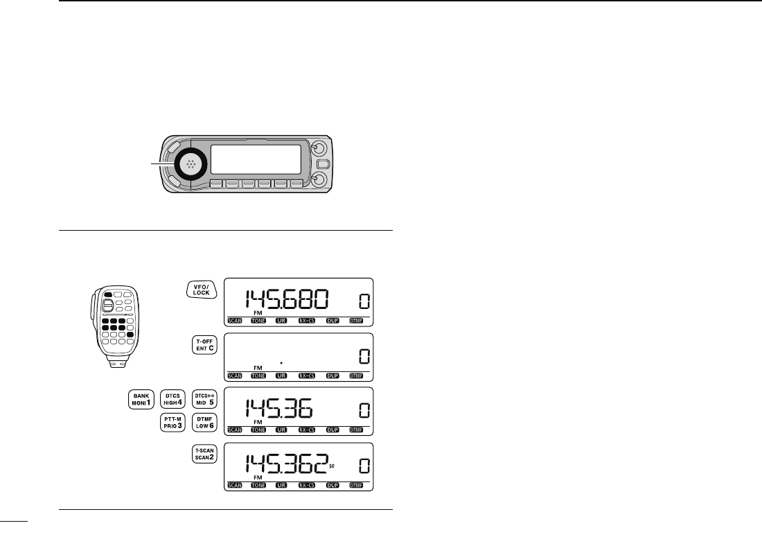
4. Tune the frequency
The tuning dial will allow you to dial in the frequency you
want to use. Pages 17 and 18 will instruct you on how to set
the tuning speed.
[DIAL]
Rotate [DIAL] to tune the frequency.
Using the HM-133
You can directly enter the frequency with the HM-133 keypad.
[EXAMPLE]: Setting frequency to 145.3625 MHz.
Push
Push
Push
Push

X
QUICK REFERENCE GUIDE
1
2
3
4
5
6
7
8
9
10
11
12
13
14
15
16
17
18
19
N Repeater operation
1. Setting duplex
± Push [BAND] then rotate [DIAL] to select the frequency
band. Then rotate [DIAL] to select the repeater frequency.
± Push and hold [DUP](LOW) for 1 sec. then rotate [DIAL]
to select minus duplex or plus duplex.
• The USA version has an auto repeater function, therefore, set-
ting duplex is not required.
[DUP][DIAL]
2. Repeater tone
Push and hold [TONE](M/CALL) for 1 sec. then rotate [DIAL]
to select “TONE,” if the repeater requires a subaudible tone
to be accessed.
[TONE][DIAL]
Using the HM-133
Plus or minus duplex selection and the repeater tone setting
can be made easily via the HM-133.
Push [DUP– 7(TONE)] for minus duplex; [DUP+ 8(TSQLS)]
for plus duplex selection, push [FUNC] then [DUP– 7(TONE)]
to turn the repeater tone ON.
Push
Push , then
Push

XI
QUICK REFERENCE GUIDE
The ID-880H has a total of 1052 memory channels (including
25 pairs scan edges and 2 call channels) for storing often used
operating frequency, repeater settings, etc.
1. Setting a frequency
In VFO mode, set the desired operating frequency with re-
peater, tone and tuning steps, etc.
± Push [VFO/MHz] to select VFO.
±
Rotate [DIAL] to set the desired frequency.
• Set other data, such as repeater tone, duplex information, tuning
step), if desired.
2. Selecting a memory channel
Push [S.MW], then rotate [DIAL] to select the desired mem-
ory channel.
• “X” indicator and memory channel number blink.
[S.MW ]
3. Writing a memory channel
Push and hold [MW](S.MW) for 1 sec. to program.
• 3 beeps sound
• Return to VFO mode automatically after programming.
• Memory channel number automatically increases when continuing
to push [MW](S.MW) after programming.
Using the HM-133
q Push [MR/CALL] to select memory mode.
w Push [ENT C(T-OFF)] first, then enter the desired memory
channel via the keypad.
e Push [VFO/LOCK] to select VFO mode, then set the de-
sired operating frequency, including offset direction, tone
settings, etc.
± Push [VFO/LOCK] to select VFO.
± Push [ENT C(T-OFF)] first, then enter the desired operat-
ing frequency via the keypad.
• Set other data, such as repeater tone, duplex information,
tuning step, if necessary.
r Push [FUNC] then push and hold [CLR A(MW)] for 1 sec. to
program.
Push , then
• 3 beeps sound
• Memory channel number automatically increases when continu-
ing to push [CLR A(MW)] after programming.
N Programming memory channels
1
1
PANEL DESCRIPTION
1
2
3
4
5
6
7
8
9
10
11
12
13
14
15
16
17
18
19
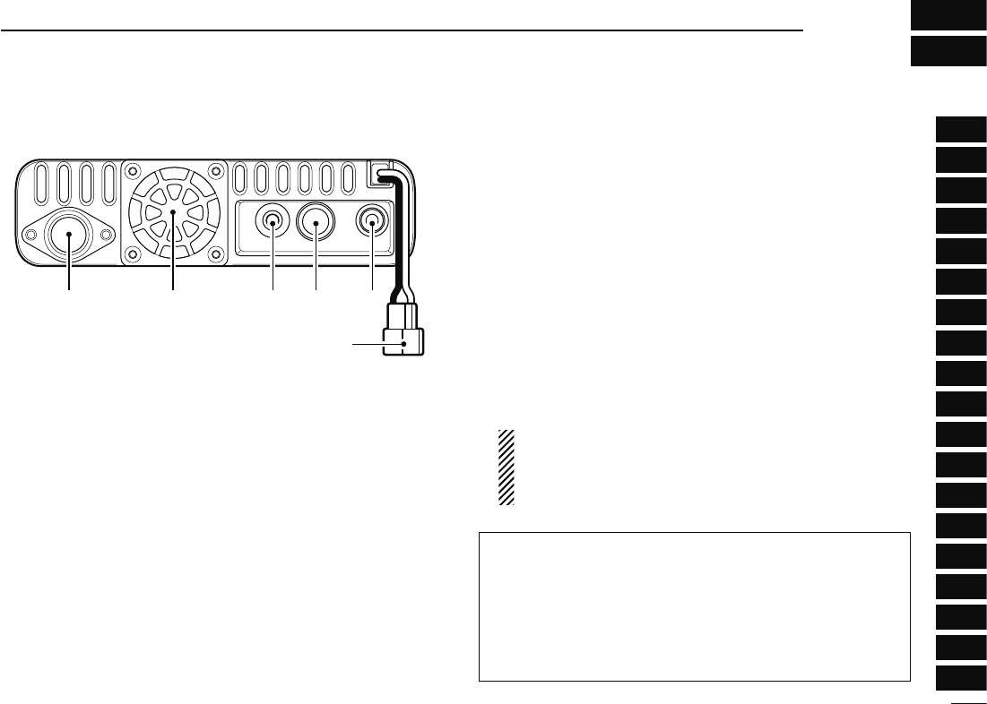
N Main unit
q e r tw
y
Rear view
q ANTENNA CONNECTOR [ANT] (p. IX)
Connects a 50 Ω antenna with a PL-259 connector and a
50 Ω coaxial cable for transmission and reception.
w COOLING FAN
Rotates while transmitting.
Also rotates while receiving depending on the setting in
FUNC set mode (SET). (p. 101)
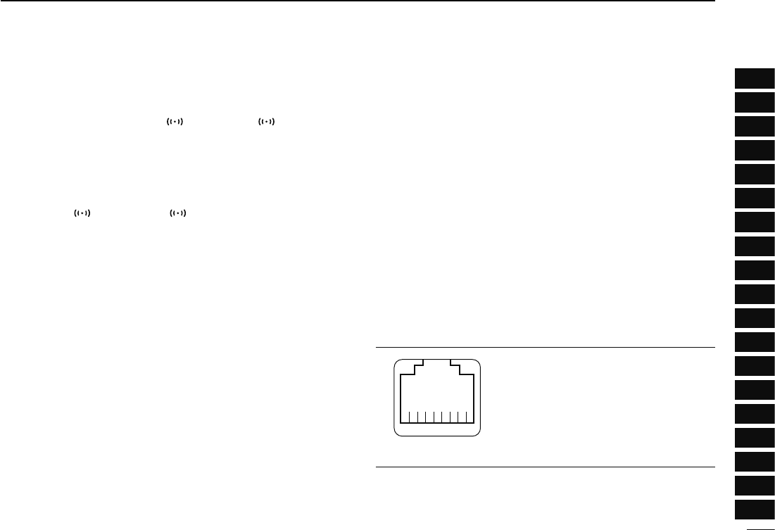
e DATA JACK [DATA] (p. 57)
± Connect a PC through the optional data communication
cable OPC-1529R, for low-speed data communication
in DV mode or data cloning with the cloning software
CS-80/880 (free download).
± Connect a GPS receiver through the optional data com-
munication cable OPC-1529R, for GPS operation.
r PACKET JACK [PACKET] (pgs. 120, 121)
Connects a TNC (Terminal Node Controller), etc. for data
communications. The receiver can support 1200/9600 bps
packet communication (AFSK/GMSK).
t EXTERNAL SPEAKER JACK [SP]
± Connects an 8 Ω speaker.
• Audio output power is more than 2.0 W.
± Connect an optional cloning cable OPC-478UC or OPC-
474 for data cloning.
y POWER RECEPTACLE [DC13.8V]
Accepts 13.8 V DC ±15% with the supplied DC power
cable.
NOTE: DO NOT use a cigarette lighter socket as a
power source when operating in a vehicle. The plug
may cause voltage drops and ignition noise may be su-
perimposed onto transmit or receive audio.
ANTENNA INFORMATION
For radio communications, the antenna is of critical impor-
tance, to maximize your output power and receiver sensitiv-
ity. The transceiver accepts a 50 Ω antenna and a Voltage
Standing Wave Ratio (VSWR) of 1.5:1 or less. High SWR
values not only may damage the transceiver but also lead
to TVI or BCI problems.
2
2BASIC OPERATION
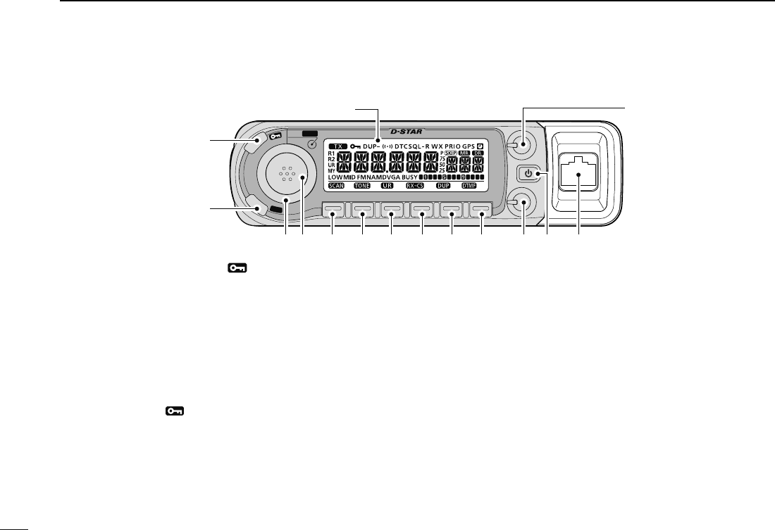
q MENU•LOCK KEY [MENU ]
± Push to enter menu screen indication ON and OFF.
(p. 7)
± Push and hold for 1 sec. to toggle the lock function ON
and OFF. (p. 19)
w SELECT MEMORY WRITE•MEMORY WRITE KEY
[S.MW•MW]
± Push to enter select memory write mode for memory
channel programming. (pgs. 62, 73, 76)
• Push [MENU ] to cancel and exit the select memory write
mode.
± Push and hold to store the frequency, operating mode,
etc. into the selected memory channel. (pgs. 62, 73, 76)
e TUNING DIAL [DIAL]
Selects the operating frequency (p. 17), memory channel
(p. 61), the setting of the set mode item and the scanning
direction (p. 75).
r BAND•MODE KEY [BAND•MODE]
± Push to enter band selection state. (p. 15)
• Rotating [DIAL] selects the band.
± Push and hold for 1 sec. to enter operating mode selec-
tion state. (p. 15)
• Rotating [DIAL] selects the operating mode.
t VFO/MHz TUNING•SCAN KEY [VFO/MHz•SCAN]
± Push to select VFO mode. (p. 17)
± During VFO mode operation, push to select 1 MHz and
10 MHz tuning steps. (p. 75)
± Push and hold for 1 sec. to enter scan type selection
state. (p. 75)
• Cancels a scan when pushed during scan.
y MEMORY/CALL•TONE KEY [M/CALL•TONE]
± Push to select memory, call and weather channel*
modes. (pgs. 61, 72, 123)
*Weather channels are available for USA version only.
N Front panel— controller
VFO/MHz
BAND
MODE
VOL
SQL
M/CALL CSDR LOW
MONI
S
.
M
W
M
W
M
E
N
U
uytr!0oi
Function display (p. 3)
w
q
e
!4
!3!2!1
3
2
BASIC OPERATION
1
2
3
4
5
6
7
8
9
10
11
12
13
14
15
16
17
18
19
± During FM/FM-N mode operation, push and hold for 1
sec. to enter tone function selection state. (pgs. 86, 91)
• Rotating [DIAL] selects the tone function.
• T (Repeater tone), TSQL , TSQL, DTCS , DTCS, tone
squelch reverse, DTCS squelch reverse or tone function OFF
can be selected.
± During DV mode operation, push and hold for 1 sec. to
select digital call sign squelch, digital code squelch and
no squelch operation in sequence. (p. 149)
• DSQL , DSQL, CSQL , CSQL or digital call squelch
OFF can be selected.
u D-STAR REPEATER•YOUR KEY [DR•UR]
± Push to select DR mode. (p. 21)
• Rotating [DIAL] selects access repeater.
• DV mode is automatically selected.
± During DV mode operation, push and hold for 1 sec. to
enter your call sign selection state. (p. 30)
• Rotating [DIAL] selects your call sign.
• DV mode is automatically selected.
i CALL SIGN•RX CALL WRITE KEY [CS•RXCS]
± Push to display the current call sign. (p. 21)
• Rotating [DIAL] selects UR (your) call sign, R1 (access re-
peater) call sign, R2 (link repeater) call sign and MY (your
own) call sign.
± Push and hold for 1 sec. to set the received call signs
(stations and repeaters) to current call sign. (p. 30)
o OUTPUT POWER•DUPLEX KEY [LOW•DUP]
± Each push changes the output power selection. (p. 21)
• LOW, MID and HIGH (no indicator visible) are available.
± Push and hold for 1 sec. to enter duplex operation se-
lection state. (p. 30)
• Rotating [DIAL] selects the tone function.
• DUP– (minus duplex), DUP (plus duplex) and simplex (no
indicator visible) are available.
!0 MONITOR•DTMF KEY [MONI•DTMF]
± Push to turn the monitor function ON and OFF. (p. 24)
± Push and hold for 1 sec. to enter DTMF set mode.
(p. 82)
!1 SQUELCH CONTROL [SQL]
Varies the squelch level for left and right band. (p. 20)
• The RF attenuator activates and increases the attenuation when
rotated clockwise at and beyond the center position. (p. 22)
!2 POWER KEY [PWR]
Push and hold for 1 sec. to turn power ON and OFF.
!3 MICROPHONE CONNECTOR (p. IV)
Connects the supplied or an optional microphone.
:
2
q +8 V DC output (Max. 10 mA)
w Channel up/down
e 8 V control IN
r PTT
t GND (microphone ground)
y MIC (microphone input)
u GND
i Data IN
!4 VOLUME CONTROL [VOL] (p. 20)
Adjusts the audio level for left or right band.
4
1PANEL DESCRIPTION
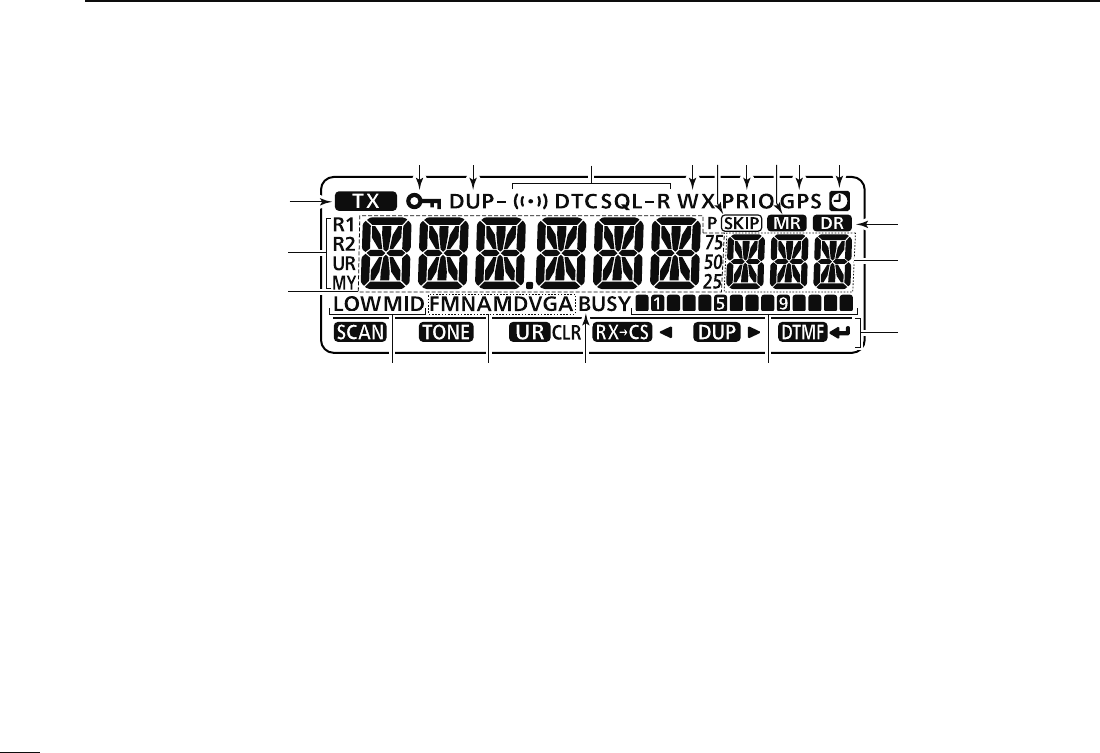
N Function display
!1!8 !6 !4 !2!5 !3
o
!0
q
w
!7
i
rty u
e
Function guide (p. 5)
q TRANSMIT INDICATOR
± Appears while transmitting. (p. 17)
w CALL SIGN TYPE INDICATORS
“MY” appears when your own call sign; “UR” appears when
station call sign; “R1” appears when access repeater call
sign and “R2” appears when link repeater call sign is se-
lected.
e FREQUENCY READOUT
Shows the operating frequency, set mode contents, etc.
• Frequency decimal point blinks while scanning. (p. 75)
r OUTPUT POWER INDICATORS
“LOW” appears when low output power; “MID” appears
when middle output power, no indication appears when
high output power is selected.
t OPERATING MODE INDICATOR (p. 21)
Shows the selected operating mode.
• FM, FMN (FM narrow), AM, NAM (AM narrow) and DV (Digital
voice) are available.
• “DVG” “DV A” appears when GPS transmission or GPS-A trans-
mission is selected in DV mode. (p. ???)
y BUSY INDICATOR
± Appears when a signal is being received or the squelch
is open. (p. 20)
± Blinks while the monitor function is activated. (p. 24)
u S/RF INDICATORS
± Shows the relative signal strength while receiving sig-
nals. (p. 20)
± Shows the output power level while transmitting. (p. 21)

5
1
PANEL DESCRIPTION
1
2
3
4
5
6
7
8
9
10
11
12
13
14
15
16
17
18
19
i MEMORY CHANNEL NUMBER INDICATORS
± Shows the selected memory channel number. (p. 61)
± Shows the selected bank initial. (p. 64)
± “C0” or “C1” appears when the call channel is selected.
(p. 72)
o DR (D-STAR REPEATER) INDICATOR (p. 118)
Appears when DR mode is selected.
!0 AUTO POWER OFF INDICATOR (p. 118)
Appears when the auto power OFF function is in use.
!1 GPS INDICATOR (p. 126)
Appears while GPS function* is in use.
• GPS indicator can be turned OFF in GPS.SET mode. (p.???).
*Available when GPS receiver is connected.
!2 MEMORY INDICATOR (p. 61)
Appears when memory mode is selected.
!3 PRIORITY INDICATOR (p. 81)
Appears while priority watch is activated, blinks while pri-
ority watch is paused.
!4 SKIP INDICATOR (p. 79)
± “” appears when the displayed memory channel is
specified as a skip channel.
± “” appears when the displayed frequency is speci-
fied as a program skip frequency.
!5 WEATHER ALERT INDICATOR (p. 123)
“WX” appears when the weather alert function is in use.
*Available with the USA version only.
!6 TONE INDICATOR
• During FM/FM-N mode operation:
± “T” appears while the repeater tone is in use. (p. 30)
± “TSQL” appears while the tone squelch function is in
use. (p. 86)
± “TSQL-R” appears while the reverse tone squelch
function is in use. (p. 87)
± “DTCS” appears while the DTCS squelch function is
in use. (p. 86)
± “DTCS-R” appears while the reverse DTCS squelch
function is in use. (p. 87)
± “” appears with the “TSQL” or “DTCS” indicator
while the pocket beep function is in use. (pgs. 86, 91)
• During DV mode operation:
± “DSQL” appears while the digital call sign squelch
function is in use. (p. 91)
± “CSQL” appears while the digital code squelch
function is in use. (p. 91)
± “” appears with the “DSQL”* or “C SQL” indicator
while the pocket beep function is in use. (pgs. 86, 91)
!7 DUPLEX INDICATORS (p. 30)
“DUP” appears when plus duplex, “DUP–” appears when
minus duplex (repeater) operation is selected.
!8 KEY LOCK INDICATOR (p. 19)
Appears when the key lock function is activated.
6
1PANEL DESCRIPTION
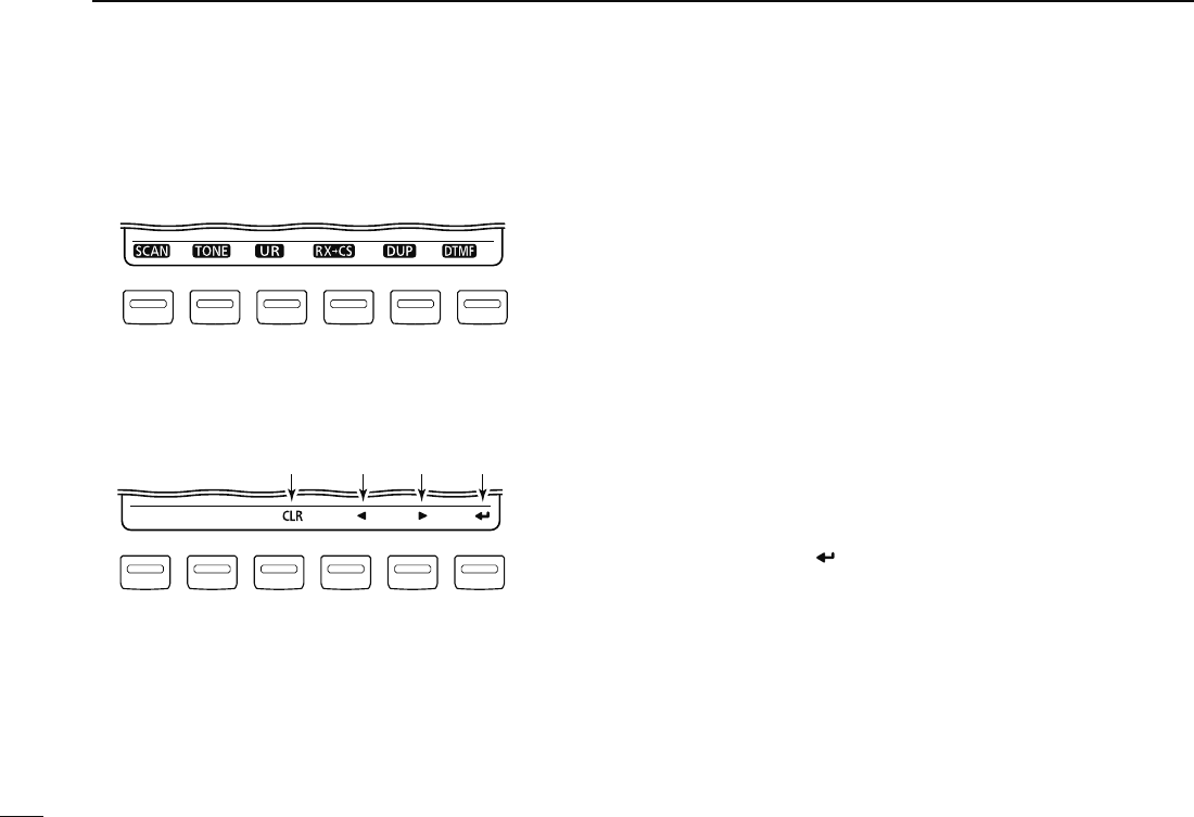
D Function guide indicator
The function guide indicators allow you to simply using a vari-
ety of functions. Two types of guide are available.
• Secondary function guides
VFO/MHz
M/CALL CSDR LOW
MONI
These function guides indicate the secondary functions for
below the keys. Push and hold for 1 sec to activate the indi-
cated functions. See page 1 to 2 (t to !0).
• Set condition guides
VFO/MHz
M/CALL CSDR LOW
MONI
qwer
Set condition guides appear when the transceiver enters
menu screen, select memory write state, optional UT-123 is
installed and GPS function is set to ON.
q CLEAR KEY [CLR](DR) (p. 39)
± During programming state for call signs, repeater list,
memory name, etc., push to erase the selected char-
acter.
± During programming state for call signs, repeater list,
memory name, etc., push and hold for 1 sec. to erase
all character following the corsor.
w LEFT KEY [](CS)
± During programming state for call signs, repeater list,
memory name, etc., push to move the cursor left.
± During menu screen operation, push to select the upper
layer. (p. 113)
e RIGHT KEY [](LOW)
± During programming state for call signs, repeater list,
memory name, etc., push to move the cursor right.
± During menu screen operation, push to select the lower
layer. (p. 113)
r ENTER KEY [ ](MONI) (p. 48)
± During menu screen operation, push to enter or exit
to/from the selected set items, etc. (p. 113)
± During programming state for call signs, repeater list,
etc., push to set or store the setting.
7
1
PANEL DESCRIPTION
1
2
3
4
5
6
7
8
9
10
11
12
13
14
15
16
17
18
19
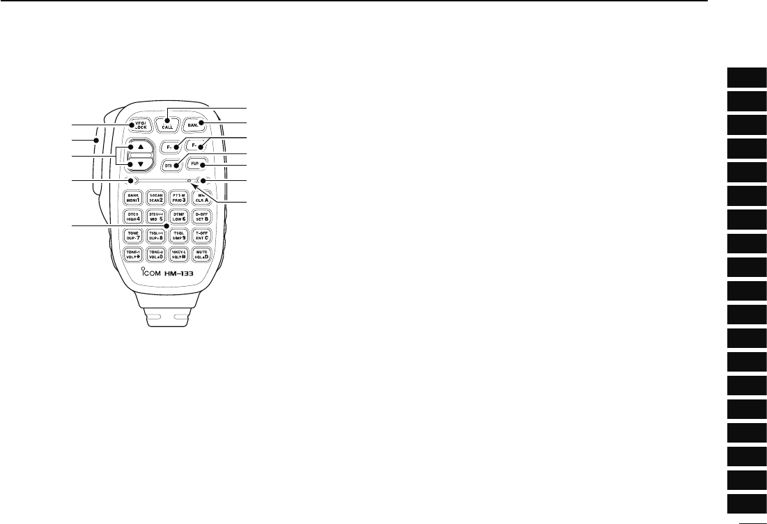
N Microphone (HM-133*)
Mic element
q
e
r
t
w
y
u
i
o
!0
!1
q VFO/LOCK KEY [VFO/LOCK]
± Push to select VFO mode. (p. 16)
± Push and hold for 1 sec. to turn the lock function ON
and OFF. (p. 19)
w PTT SWITCH
± Push and hold to transmit; release to receive.
± Switches between transmitting and receiving while the
one-touch PTT function is in use. (p. 26)
e UP/DOWN KEYS [Y]/[Z]
± Push either key to change operating frequency, memory
channel, set mode setting, etc. (pgs. 17, 61, 98)
± Push and hold either key for 1 sec. to start scanning.
(p. 75)
r ACTIVITY INDICATOR
± Lights red while any key, except [FUNC] and [DTMF-S],
is pushed, or while transmitting.
± Lights green while the one-touch PTT function is in
use.
t KEYPAD (pgs. 12, 13)
y FUNCTION INDICATOR
± Lights orange while [FUNC] is activated—indicates the
secondary function of keys can be accessed.
± Lights green when [DTMF-S] is activated—DTMF sig-
nals can be transmitted with the keypad.
u 2nd FUNCTION KEY [FUNC]
i DTMF SELECT KEY [DTMF-S] (p. 84)
o FUNCTION KEYS [F-1]/[F-2] (p. 115)
Program and recall your desired transceiver configuration.
!0 BAND KEY [BAND] (p. 15)
Push to select main band between left and right bands.
!1 MEMORY/CALL KEY [MR/CALL]
± Push to select memory mode. (p. 61)
± Push and hold for 1 sec. to select call channel. (p. 72)
8
1PANEL DESCRIPTION
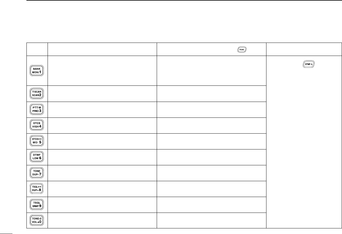
N Microphone keypad
KEY FUNCTION SECONDARY FUNCTION ( +key) OTHER FUNCTIONS
Switches between opening and closing the
squelch. (p. 24)
Starts and stops scanning. (p. 75)
Starts and stops priority watch. (p. 81)
Selects high output power. (p. 21)
Selects mid. output power. (p. 21)
Selects low output power. (p. 21)
Selects minus duplex operation. (p. 31)
Selects plus duplex operation. (p. 31)
Selects simplex operation. (p. 31)
Increases audio output level. (p. 20)
In VFO mode enters operating band selec-
tion.
In memory mode enters bank selection.
(p. 64)
Starts and stops tone scanning. (p. 90)
Turns the one-touch PTT function ON and
OFF. (p. 26)
Turns the DTCS squelch ON. (p. 86)
Turns the DTCS pocket beep function ON.
(p. 86)
Turns the DTMF memory encoder function
ON. (p. 83)
Turns the subaudible tone encoder ON.
(p. 31)
Turns the CTCSS pocket beep function ON.
(p. 86)
Turns the tone squelch function ON.
(p. 86)
Sends a 1750 Hz tone signal while pushing
and holding. (p. 33)
After pushing :
Transmits the appropri-
ate DTMF code. (pgs. 33, 84)
When the DTMF memory en-
coder is activated, push [0] to
[9] to transmit the appropriate
DTMF memory contents .
(p. 84)

9
1
PANEL DESCRIPTION
1
2
3
4
5
6
7
8
9
10
11
12
13
14
15
16
17
18
19
±Cancels frequency entry. (p. 17)
± Cancels the scan or priority watch.
(pgs. 75, 81)
±Exit set mode. (p. 98)
± Enters MENU screen. (p. 98)
± Enters selected set mode. (p. 98)
± Enters programmable condition after se-
lecting a set mode item. (p. 98)
± Sets the keypad for numeral input.
(p. 17)
± Returns to the previous indication after
entering set mode. (p. 98)
Adjusts the squelch level increments.
(p. 20)
Decreases audio output level. (p. 20)
Adjusts the squelch level decrement.
(p. 20)
± Stores the set frequency, etc., into the
selected memory channel when pushed
and held. (p. 63)
± Advances the memory channel number
when continuously pushed after pro-
gramming is completed. (p. 63)
DTMF memory encoder function OFF.
(p. 83)
Turns the subaudible tone encoder, pocket
beep or CTCSS/DTCS tone squelch OFF.
(pgs. 31, 86)
Mutes the audio. (p. 27)
• Mute function is released when any op-
eration is performed.
Sends a 1750 Hz tone signal for 0.5 sec.
(p. 33)
Locks the digit keys on the keypad (includ-
ing the A to D, # and M keys. (p. 19)
After pushing :
Transmits the appropri-
ate DTMF code. (pgs. 33, 84)
KEY FUNCTION SECONDARY FUNCTION ( +key) OTHER FUNCTIONS
10
1PANEL DESCRIPTION
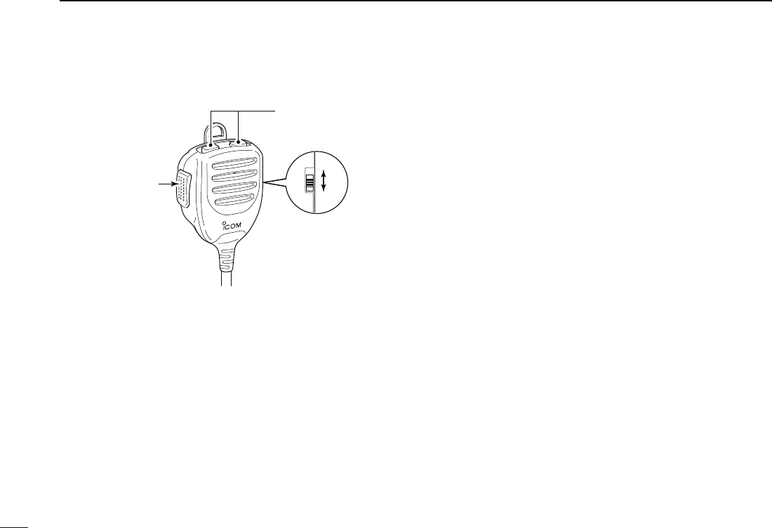
N Optional Microphone (HM-154)
4
/
ON
OFF
)
q PTT SWITCH
Push and hold to transmit; release to receive.
w UP/DOWN KEYS [UP]/[DN]
± Push either key to change operating frequency, memory
channel, set mode setting, etc. (pgs. 17, 61, 98)
± Push and hold either key for 1 sec. to start scanning.
(p. 75)
e UP/DN LOCK SWITCH
Slide to toggle [UP]/[DN] keys function ON and OFF.
11
2
BASIC OPERATION
1
2
3
4
5
6
7
8
9
10
11
12
13
14
15
16
17
18
19
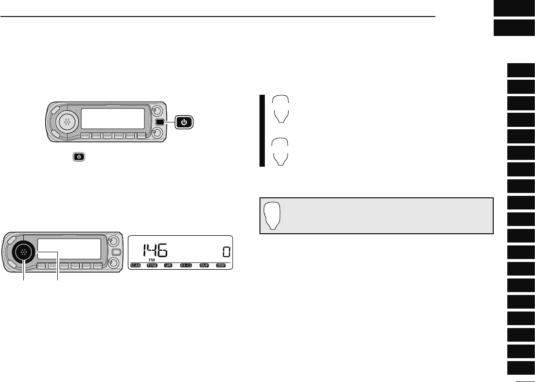
N Preparation
D Turning power ON/OFF
± Push and hold [ ] for 1 sec. to turn power ON and OFF.
D Operating frequency band selection
The ID-880H has 2 m and 70 cm bands for transmission and
reception. In addition, extra frequency bands 127, 220, 350,
500 and 900 MHz band are available for wide-band receiver
capability (depending on versions, see p. ?? for details).
[BAND] [DIAL] Frequency band initial is displayed.
q Push [BAND] and rotate [DIAL] to select the desired fre-
quency band.
• Pushing [Y]/[Z] on the microphone also selects the band.
w Push [BAND] to return to frequency indication in the se-
lected frequency band.
BAND
Y/Z
z Push [BAND] to enter frequency band selec-
tion.
• The frequency band is displayed.
x Push [Y]/[Z] to select the desired frequency
band.
c Push [CLR A(MW)] (or [BAND]) to exit the condi-
tion, and return to frequency indication.
Note that in this manual, sections beginning with a micro-
phone icon (as at left), designate operation via the HM-133
microphone.
12
2BASIC OPERATION
D VFO mode
VFO mode is used to set the desired frequency.
± Push [VFO/MHz] to select VFO mode.
• When VFO mode is already selected, the digits to the right of the
10 MHz or 1 MHz digits will disappear depending on version. In
this case, push [VFO/MHz] again (or twice depending on ver-
sion).
[VFO/MHz]
• VFO mode indication
VFO/LOCK
± Push [VFO/LOCK] to select VFO mode.
What is VFO?
VFO is an abbreviation of Variable Frequency Oscillator. Fre-
quencies for both transmitting and receiving are generated
and controlled by the VFO.
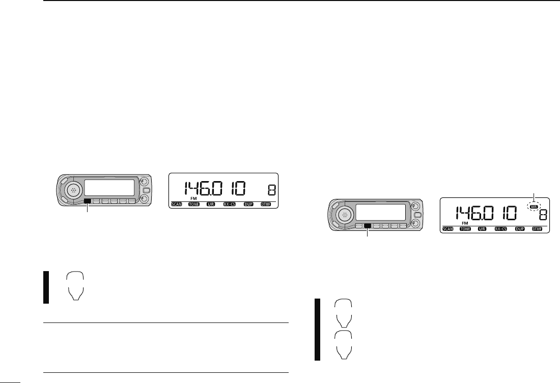
D Memory mode
Memory mode is used for operation on memory channels
which store programmed frequencies.
q Push [M/CALL] to select memory mode.
• Push [M/CALL] several times to select Memory/Call/Weather*
channels in sequence. * Weather channels are available for the
U.S.A. version only.
• “X” indicator appears when memory mode is selected.
Appears
[M/CALL]
• Memory mode indication
w Rotate [DIAL] to select the desired memory channel.
• Only programmed memory channels can be selected.
• See p. 92 for memory programming details.
MR/CALL
Y/Z
z Push [MR/CALL] to select memory mode.
x Push [] or [] to select the desired mem-
ory channel.
13
2
BASIC OPERATION
1
2
3
4
5
6
7
8
9
10
11
12
13
14
15
16
17
18
19
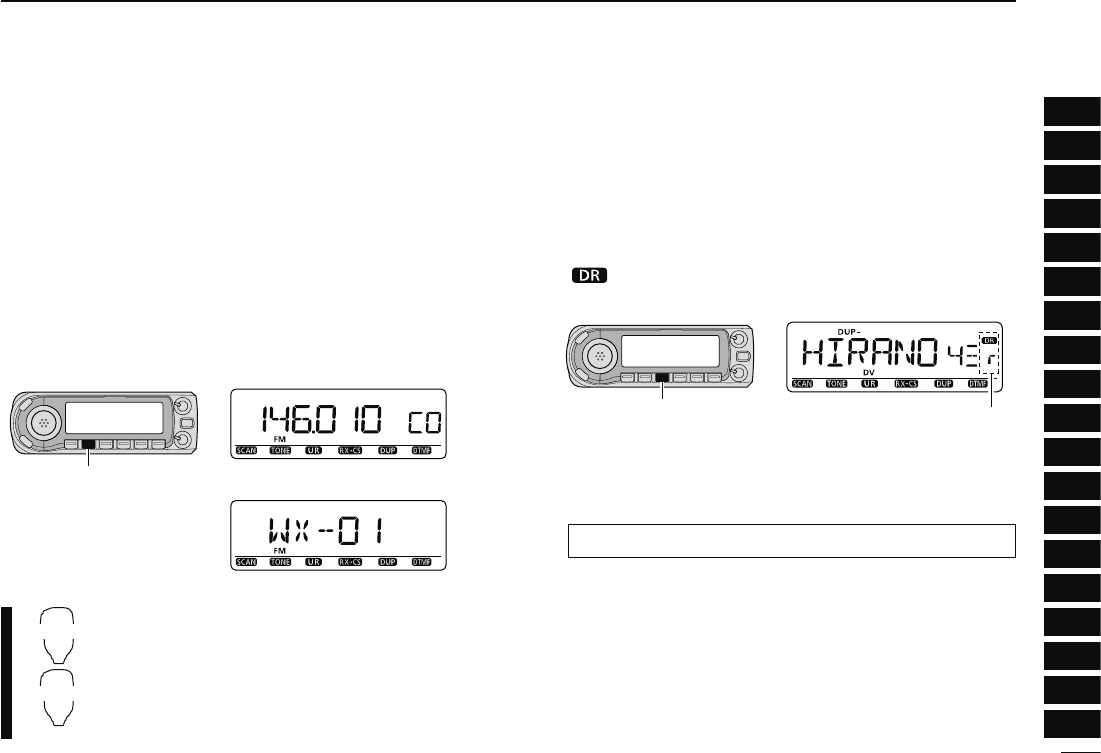
D Call/Weather* channels
Call channels are used for quick recall of most-often used
frequencies. *Weather channels are available for the U.S.A.
version only.
q Push [M/CALL] several times to select call channels/
Weather channels.
• Memory/Call/Weather channels can be selected in sequence.
• “C0” or “C1” appears when call channel is selected.
w Rotate [DIAL] to select the desired channel.
[M/CALL]
• Call channel indication
• Weather channel indication
MR/CALL
Y/Z
z Push and hold [MR/CALL] for 1 sec. to se-
lect call channels.
• Whether channels cannot be selected by the
HM-133.
x Push [] or [] to select the desired call
channel.
D DR (D-STAR Repeater) mode
DR (D-STAR Repeater) mode is used for the D-STAR re-
peater operation. In this mode, you can select the pre-pro-
grammed repeaters and UR (your) call sign easily.
q Push [DR] to select DR mode.
• “ ” appears when call channel is selected.
[DR]
• DR mode indication
Appear
w Rotate [DIAL] to select the desired access repeater.
• While rotating [DIAL], S/RF-meter indicates group number.
• Only programmed access repeaters in RPT-L menu can be se-
lected. See p. 40 for RPT-L (repeter lists) programming details.
MENU ¶RPT-L ¶ADD-L (p. 40)
14
2BASIC OPERATION
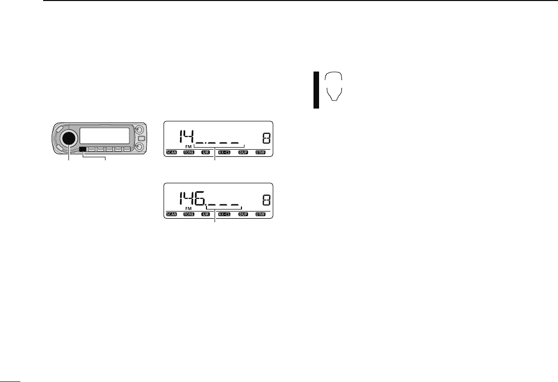
N Using the tuning dial
q Rotate [DIAL] to set the frequency.
• If VFO mode is not selected, push [VFO/MHz] to select VFO
mode.
• The frequency changes in the selected tuning steps. (p. 18)
[DIAL] [VFO/MHz]
While 1 MHz tuning step is selected,
the digit below 100kHz disappear.
While 10 MHz tuning step is selected,
the digit below 1 MHz disappear.
w
To change the frequency in 1 MHz (10 MHz for some versions)
steps, push [VFO/MHz], then rotate [DIAL].
• Pushing and holding [VFO/MHz] for 1 sec. starts scan function.
If scan starts, push [VFO/MHz] again to cancel it.
N Using the [Y]/[Z] keys
YZ
± Push [Y] or [Z] to select the desired frequency.
• Pushing and holding [Y]/[Z] for 1 sec. activates a
scan. If scan starts, push [Y]/[Z] or [CLR A(MW)] to
cancel it.
15
2
BASIC OPERATION
1
2
3
4
5
6
7
8
9
10
11
12
13
14
15
16
17
18
19
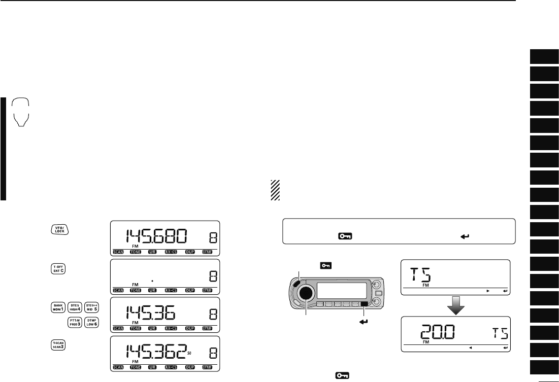
N Using the keypad
The frequency can be directly set via numeral keys on the
microphone.
ENT
C
z Push [BAND] to select the desired band (left or
right) as the main band.
• Push [VFO/LOCK] to select VFO mode, if necessary.
x Push [ENT C(T-OFF)] to activate the keypad for
digit input.
c Push 6 keys to input a frequency.
• When a digit is mistakenly input, push [ENT C(T-OFF)]
to clear the input, then repeat input from the 1st digit.
• Pushing [CLR A(MW)] clears input digits and retrieves
the frequency.
Push
Push
Push
Push
[EXAMPLE]: Setting frequency to 145.3625 MHz.
N Tuning step selection
Tuning steps are the minimum frequency change increments
when you rotate [DIAL] or push [Y]/[Z] on the microphone.
Independent tuning steps for the left and right bands, as well
as each frequency band can be set for individual tuning con-
venience. The following tuning steps are available.
• 5 kHz* • 6.25 kHz* • 10 kHz • 12.5 kHz
• 15 kHz* • 20 kHz • 25 kHz • 30 kHz
• 50 kHz • 100 kHz • 125 kHz • 200 kHz
*Not selectable in 900 MHz band.
NOTE: For convenience, select a tuning step that matches
the frequency intervals of repeaters in your area.
q
Enter “TS” in MENU screen.
MENU ¶ TS
(p. 63)
(Push [MENU ]), (Rotate [DIAL], then push [ ](MONI).)
• Push [VFO/MHz] to select VFO mode, if necessary.
[DIAL]
[MENU ]
[ ]
w Rotate [DIAL] to select the desired tuning step.
e Push [MENU ] to exit the set mode.
16
2BASIC OPERATION
N Lock functions
To prevent accidental frequency changes and unnecessary
function access, use the lock function. The transceiver has 2
different lock functions.
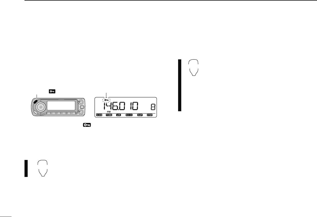
D Frequency lock
This function locks [DIAL] and keys electronically and can be
used together with the microphone lock function.
[MENU ] Appears
± Push and hold [MENU ] for 1 sec. to turn the lock func-
tion ON and OFF.
• [PTT], [MONI] (monitor function only), [VOL] and [SQL] can be
used while the channel lock function is in use. Also, TONE-1,
TONE-2, DTMF tones or DTMF memory contents can be trans-
mitted from the microphone.
VFO/LOCK
± Push and hold [VFO/LOCK] for 1 sec. to
turn the lock function ON and OFF.
D Microphone keypad lock
This function locks the microphone keypad.
16KEY-L
± Push [FUNC] then [SQLZ D(16KEY-L)] to turn
the microphone keypad lock function ON and
OFF.
• [PTT], [VFO/LOCK], [MR/CALL], [BAND], [Y], [Z],
[F-1], [F-2], [DTMF-S] and [FUNC] on the micro-
phone can be used.
• All keys on the transceiver can be used.
• The keypad lock function is released when the
power is turned OFF then ON again.
17
2
BASIC OPERATION
1
2
3
4
5
6
7
8
9
10
11
12
13
14
15
16
17
18
19
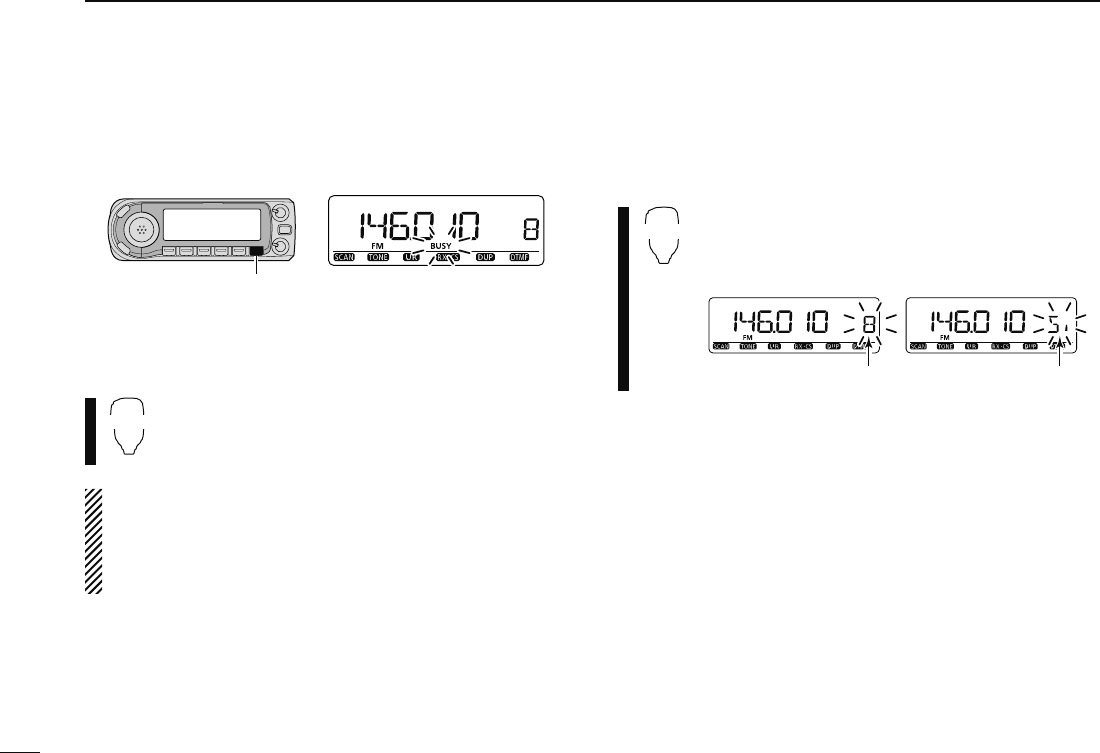
N Receiving
q Set the audio level.
± Push [MONI] to open the squelch.
± Rotate [VOL] to adjust the audio level.
± Push [MONI] to close the squelch.
w Set the squelch level.
± Rotate [SQL] fully counterclockwise in advance, then
rotate [SQL] clockwise until the noise just disappears.
• When interference due to strong signals is received, rotate
[SQL] clockwise past 12 o'clock for attenuator operation.
(p. 22)
e Set the operating frequency. (pgs. 15–17)
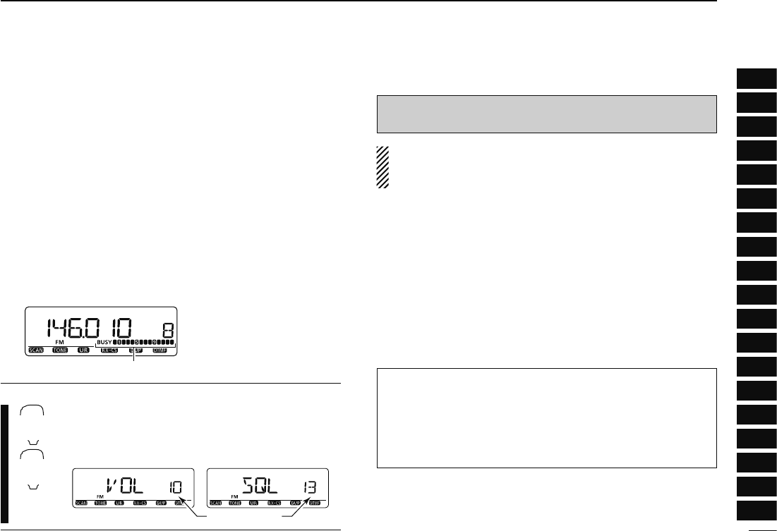
r When receiving a signal on the selected frequency, squelch
opens and the transceiver emits audio.
Appears when receiving a signal.
• “BUSY” appears and the S/RF
indicator shows the relative
signal strength for the re-
ceived signal.
CONVENIENT!
SQL2/3
D/#
VOL2/3
&/0
The audio and squelch level can also be adjusted with
[VOLY(TONE-1)]/[VOLZ 0(TONE-2)] and
[SQLY D(MUTE)]/[SQLZ #(16KEY-L)], respectively.
• “VOL” for audio or “SQL” for squelch appears during set.
Show set level
N Transmitting
CAUTION: Transmitting without an antenna may damage
the transceiver.
NOTE: To prevent interference, listen on the channel be-
fore transmitting by pushing [MONI], or [MONI 1(BANK)] on
the microphone.
q Set the operating frequency. (pgs. 15–17)
• Select output power if desired. See section at right for details.
w Push and hold [PTT] to transmit.
• “$” appears.
• The S/RF indicator shows the output power selection.
• A one-touch PTT function is available. See p. 26 for details.
e Speak into the microphone using your normal voice level.
• DO NOT hold the microphone too close to your mouth or speak
too loudly. This may distort the signal.
r Release [PTT] to return to receive.
IMPORTANT! (for 50 W transmission):-
The ID-880H is equipped with protection circuits to protect
the power amplifier circuit from high temperature. When
the transceiver temperature becomes extremely high, the
transceiver reduces transmit output power to 5 W (approx.)
automatically.
18
2BASIC OPERATION
N Selecting output power
The transceiver has 3 output power levels to suit your operat-
ing requirements. Low output powers during short-distance
communications may reduce the possibility of interference to
other stations and will reduce current consumption.
± Push [LOW] several times to select the output power.
*approx.
• The output power can be changed while transmitting.
The microphone can also be used to select output power.
HIGH
4
MID
5
LOW
6
± Push [HIGH 4(DTCS)] for high output power;
[MID 5(DTCSS)] for middle output power; and
[LOW 6(DTMF)] for low output power.
• The output power can be changed via the microphone
during receive only.
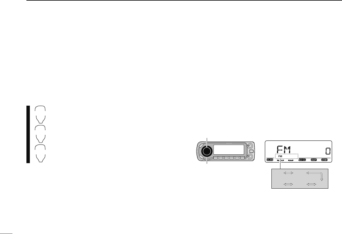
N Operating mode selection
Operating modes are determined by the modulation of the
radio signals. The transceiver has total 5 operating modes
(FM, FM-N, AM, AM-N and DV* modes). The mode selection is
stored independently for each band and memory channel.
Typically, AM mode is used for the air band (118–136.995 MHz),
and receive is only available.
q Select the desired frequency band in VFO mode, or the
desired memory channel.
w Push and hold [MODE](BAND) for 1 sec., then rotate
[DIAL] to select the desired operating mode from FM,
FMN, AM, NAM and DV.
[DIAL]
[MODE]
Selected operating mode is displayed.
FM FMN
NAM AMDV
19
2
BASIC OPERATION
1
2
3
4
5
6
7
8
9
10
11
12
13
14
15
16
17
18
19
N Squelch attenuator
The transceiver has an RF attenuator related to the squelch
level setting. Approx. 10 dB attenuation is obtained at maxi-
mum setting.
The squelch attenuator allows you to set the minimum signal
level needed to open the squelch. The attenuator function can
be deactivated in set mode.
± Rotate [SQL] clockwise past the 13 o’clock position to ac-
tivate the squelch attenuator.
• Attenuation level can be adjusted up to 10 dB (approx.) between
13 o’clock and fully clockwise position.
Squelch is
open.
Squelch
attenuator
Squelch
threshold
Shallow Deep
Noise squelch
NOTE: The squelch attenuator functions even when the
monitor function is in use. Thus it is recommended to set
the [SQL] control between the 10 and 13 o'clock positions
when using the monitor function.
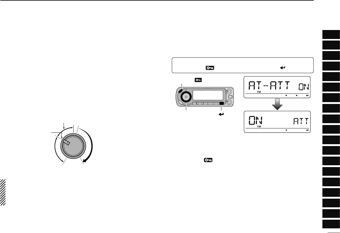
D Squelch attenuator setting
q
Enter “AT-ATT” in FUNC set mode (SET).
MENU ¶ SET ¶ FUNC ¶ AT-ATT
(p. 63)
(Push [MENU ]), (Rotate [DIAL], then push [ ](MONI).)
[DIAL]
[MENU ]
[ ]
w Rotate [DIAL] to turn the squelch attenuator function ON
and OFF.
• Select “OFF” to deactivate the squelch attenuator function.
e Push [MENU ] to exit the set mode.
20
2BASIC OPERATION
N Monitor function
This function is used to listen to weak signals without disturb-
ing the squelch setting.
[MONI]
± Push [MONI] to open the squelch.
• “BUSY” blinks.
• Push [MONI] again to cancel the function.
MONI
1
± Push [MONI 1(BANK)] to open the squelch.
• Push [BAND] to select the desired band (left or right)
as the main band in advance.
• Push [MONI 1(BANK)] again to cancel the function.
NOTE: When the [SQL] adjustment is set too far clock-
wise, (13–17 o’clock position) the squelch attenuator is
activated. To monitor weak signals on the operating fre-
quency, deactivate the squelch attenuator function. See
page 22 for details.
N Audio mute function
This function temporarily mutes the audio without disturbing
the volume setting. (microphone only)
MUTE
± Push [FUNC] then [SQLY D(MUTE)] to mute
audio signals.
• Push [CLR A(MW)] (or any other key) to cancel the
function.
Shows above indications alternately