ICOM orporated 316700 VHF/UHF Amateur Transceiver User Manual ID 880H Draft
ICOM Incorporated VHF/UHF Amateur Transceiver ID 880H Draft
Contents
- 1. User Manual 1
- 2. User Manual 2
- 3. User Manual 3
- 4. User Manual 4
User Manual 2

21
2
BASIC OPERATION
1
2
3
4
5
6
7
8
9
10
11
12
13
14
15
16
17
18
19
N One-touch PTT function
The PTT switch can be operated as a one-touch PTT switch
(each push toggles between transmit/receive). Using this
function you can transmit without pushing and holding the
PTT switch.
To prevent accidental, continuous transmissions with this
function, the transceiver has a time-out timer. See p. 101 for
details.
PTT-M
z Push [FUNC] then [PRIO 3(PTT-M)] to turn the
one-touch PTT function ON.
• The activity indicator lights green.
x Push [PTT] to transmit and push again to re-
ceive.
• A beep sounds when transmission is started and a
long beep sounds when returning to receive.
c Push [FUNC] then [PRIO 3(PTT-M)] to turn the
one-touch PTT function OFF.
• The activity indicator goes out.
22
REPEATER OPERATION
3
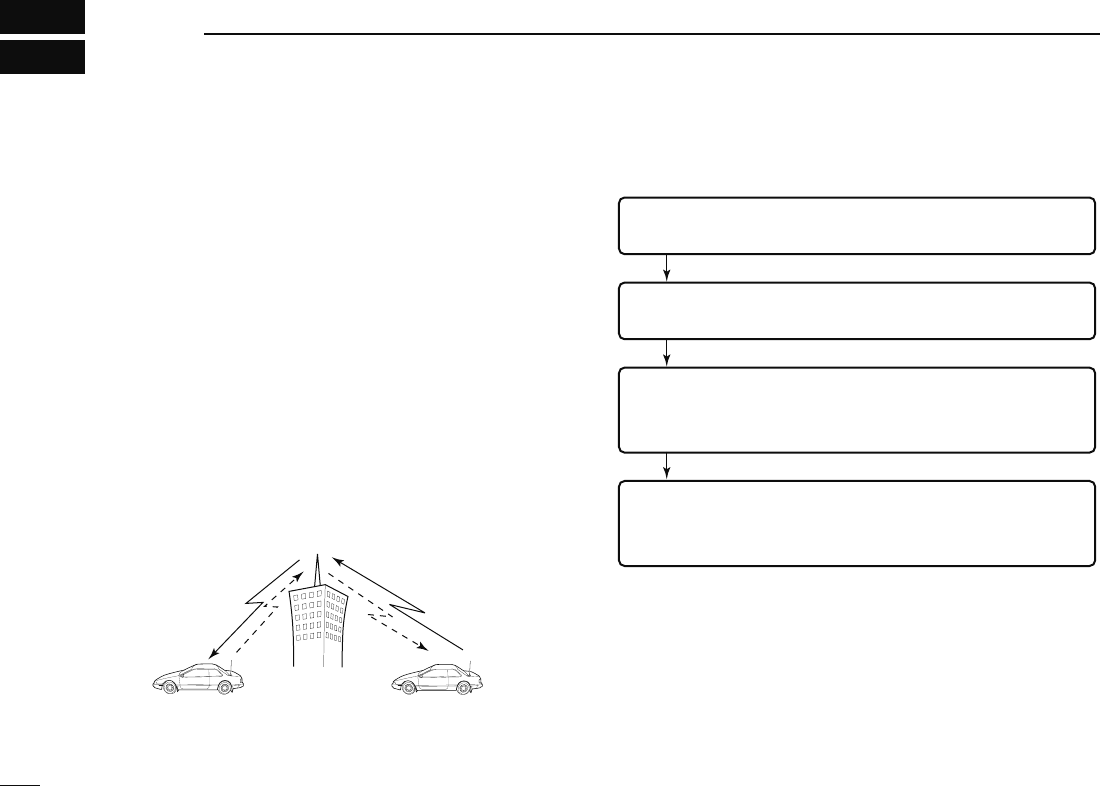
N General
Repeaters allow you to extend the operational range of your
radio because a repeater has much higher output power than
the typical transceiver.
Normally, a repeater has independent frequencies for each
receiver and transmitter.
A subaudible tone may also be required to access a re-
peater.
Reference amateur radio handbooks and local ham maga-
zines for details of local repeaters such as repeater input/out-
put frequencies and locations.
Repeater example;
Receives the 444.540 MHz signal
and the detected audio signals are
transmitted on 449.540 MHz
simultaneously.
Station A:
Tx: 444.540 MHz
Rx: 449.540 MHz
Station B:
Tx: 444.540 MHz
Rx: 449.540 MHz
• Repeater operation flow chart
Step 3:
Set the duplex (shift) direction (– duplex or +duplex).
- Set the offset frequency (amount of shift), if required.
Step 4:
Set the subaudible tone (repeater tone) encoder function ON.
- Set the subaudible tone frequency, if required.
Step 1:
Set the desired band to operate the repeater.
Step 2:
Set the desired receive frequency (repeater output frequency).
• The ID-880H USA version has the auto repeater function. Thus the
steps 3 and 4 may not be necessary, depending on the setting.
• Repeater settings can be stored into a memory channel.
23
3
REPEATER OPERATION
3
N Accessing a repeater
q Set the receive frequency (repeater output frequency).
(pgs. 15–17)
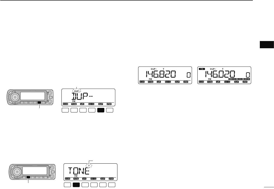
w Push and hold [DUP](LOW) for 1 sec. to enter the duplex
setting condition.
e Rotate [DIAL] to select minus duplex or plus duplex.
• “DUP–” or “DUP” appears to indicate the transmit frequency for
minus shift or plus shift, respectively.
• When the auto repeater function is turned ON (available for the
USA version only), steps w to t are not necessary. (p. 35)
[DUP]
“DUP–” or “DUP” appears
r Push and hold [TONE](M/CALL) for 1 sec. to enter the
tone setting condition.
t
Rotate [DIAL] to turn ON the subaudible tone encoder, accord-
ing to repeater requirements, then push [TONE](M/CALL).
•
“T” appears
• 88.5 Hz is set as the default; refer to p. 32 for tone frequency
settings.
• When the repeater requires a different tone system, see p. 33.
[TONE]
“T” appears
y Push and hold [PTT] to transmit.
• The displayed frequency automatically changes to the transmit
frequency (repeater input frequency).
• If
“OFF” appears, confirm that the offset frequency (p. 34) is set
correctly.
u Release [PTT] to receive.
While receiving While transmitting
i Push [MONI] to check whether the other station’s transmit
signal can be received directly.
o To return to simplex operation, push and hold [DUP](LOW)
then rotate [DIAL], to clear the “DUP–” or “DUP” indicator.
• Push [DUP](LOW) again to return to frequency indication.
!0 To turn OFF the subaudible tone encoder, push and hold
[TONE](M/CALL) then rotate [DIAL] until no tone indicator
(OFF) appears.
• Push [TONE](M/CALL) again to return to frequency indication.
24
3REPEATER OPERATION
DUP–
7
DUP+
8
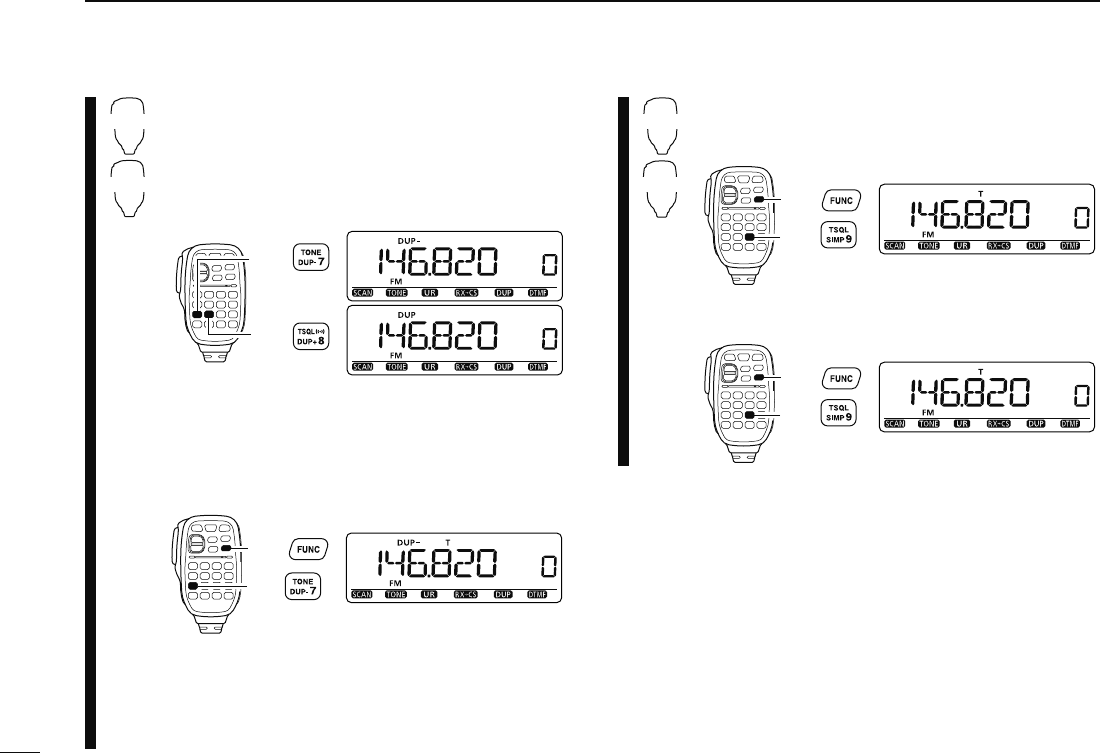
z Set the receive frequency (repeater output fre-
quency). (pgs. 16, 17)
x Push [DUP– 7(TONE)] to select minus duplex;
push [DUP+ 8(TSQLS)] to select plus du-
plex.
• “DUP–” or “DUP” appears.
Push
Push
c Push [FUNC] then [DUP– 7(TONE)] to turn ON
the subaudible tone encoder according to re-
peater requirements.
• Refer to p. 32 for the tone frequency setting.
• When the repeater requires a different tone system,
see p. 33.
Push ,
then .
v Push and hold [PTT] to transmit.
b Release [PTT] to receive.
n Push [MONI 1(BANK)] to check whether the
other station’s transmit signal can be received
directly.
SIMP
9
ENT
C
m Push [SIMP 9(TSQL)] to return to simplex opera-
tion.
• “DUP+” or “DUP–” indicator disappears.
Push ,
then .
, To turn OFF the subaudible tone encoder, push
[FUNC] then [ENT C(T-OFF)].
Push ,
then .
25
3
REPEATER OPERATION
3
N Subaudible tones (Encoder function)
D Subaudible tones
q Select mode/channel which you wish to set the subaudible
tones to, such as VFO mode or memory/call channel.
• The subaudible tone frequency is independently programmed
into each mode, band or channel.
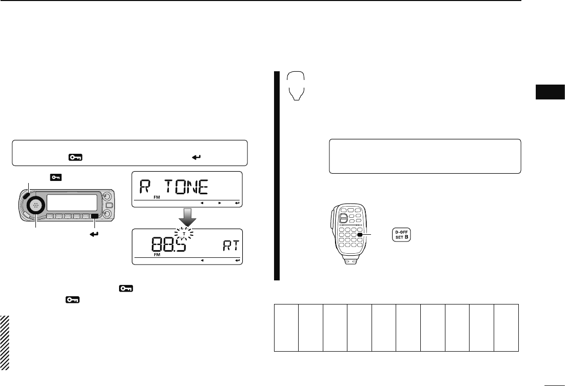
w
Enter “R TONE” in DUP.T menu.
MENU ¶ DUP.T ¶ R TONE
(p. 63)
(Push [MENU ]), (Rotate [DIAL], then push [ ](MONI).)
[DIAL]
[MENU ]
[ ]
e Rotate [DIAL] to select and set the desired subaudible fre-
quency, then push [MENU ].
r Push [MENU ] again to exit DUP.T menu.
NOTE: The subaudible tone encoder frequency can be set
in a memory/call channel temporarily. However, the set fre-
quency is cleared once another memory channel or VFO
mode is selected. To store the tone frequency permanently,
overwrite the channel information.
SET
B
z Set mode/channel which you wish to set the
subaudible tones for, such as VFO mode or
memory/call channel.
• The subaudible tone frequency is independently pro-
grammed into each mode, band or channel.
x
Enter “R TONE” in DUP.T menu.
MENU ¶ DUP.T ¶ R TONE
(p. 63)
(Push [SET B(D-OFF)] to enter MENU screen),
(Push [Y] or [Z], then push [SET B(D-OFF)].)
c Push [Y] or [Z] to select the desired
subaudible
tone frequency
then push [SET B(D-OFF)].
Push
n Push [CLR A(MW)] to return VFO mode.
• Subaudible tone frequency list (unit: Hz)
67.0
69.3
71.9
74.4
77.0
79.7
82.5
85.4
88.5
91.5
94.8
97.4
100.0
103.5
107.2
110.9
114.8
118.8
123.0
127.3
131.8
136.5
141.3
146.2
151.4
156.7
159.8
162.2
165.5
167.9
171.3
173.8
177.3
179.9
183.5
186.2
189.9
192.8
196.6
199.5
203.5
206.5
210.7
218.1
225.7
229.1
233.6
241.8
250.3
254.1
26
3REPEATER OPERATION
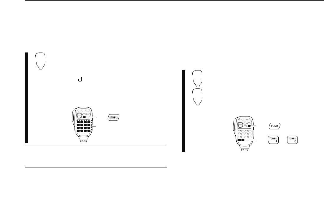
D DTMF tones
DTMF-S
± Push [DTMF-S], then push the keys of the de-
sired DTMF digits.
• The function indicator lights green.
• 0–9, A–D, 1(E) and #(F) are available.
• When “ ” is displayed in place of the 100 MHz
digit, cancel the DTMF memory encoder in ad-
vance. (p. 83)
• Push [DTMF-S] again to return the keypad to nor-
mal function control.
then push desired keys.
Push ,
-For your convenience!
The transceiver has 16 DTMF memory channels for auto-
patch operation. See p. 82 for details.
D 1750 Hz tone
The microphone has 1750 Hz tone capability, used for ring
tone when calling, etc.
TONE-1
TONE-2
z Push [FUNC].
• The function indicator lights orange.
x Push [1(TONE-1)] to transmit a 1750 Hz
tone call signal for 0.5 sec.; push and hold
[0(TONE-2)] to transmit a 1750 Hz tone call
signal for an arbitrary period.
• The function indicator goes out automatically.
Push ,
then or .
27
3
REPEATER OPERATION
3
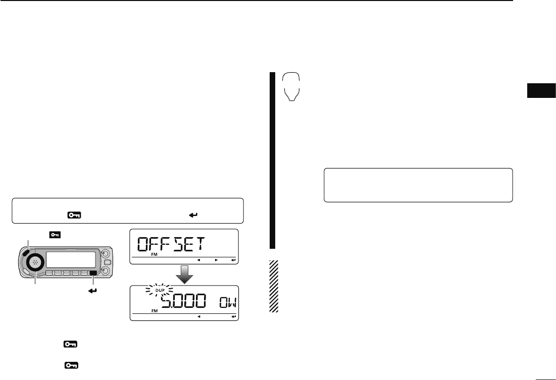
N Offset frequency
When communicating through a repeater, the transmit fre-
quency is shifted from the receive frequency by an amount
determined by the offset frequency.
Independent offset frequencies can be set for each operating
frequency band.
q Select the desired mode/channel which you wish to set the
offset frequency for, such as VFO mode or memory/call
channel.
• The offset frequency is independently programmed into each
mode, band or channel.
w
Enter “OFFSET” in DUP.T menu.
MENU ¶ DUP.T ¶ OFFSET
(p. 63)
(Push [MENU ]), (Rotate [DIAL], then push [ ](MONI).)
[DIAL]
[MENU ]
[ ]
e Rotate [DIAL] to set the desired offset frequency, then
push [MENU ].
• Push [VFO/MHz] to turn 10 MHz or 1 MHz tuning ON and OFF
r Push [MENU ] again to exit DUP.T menu.
SET
B
z Push [BAND] to select the desired band.
• Enter the desired frequency via the keypad if neces-
sary.
x Select the desired mode/channel which you
wish to set the offset frequency for, such as
VFO mode or memory/call channel.
• The offset frequency can be independently pro-
grammed into each mode, band or channel.
c
Enter “OFFSET” in DUP.T menu.
MENU ¶ DUP.T ¶ OFFSET
(p. 63)
(Push [SET B(D-OFF)] to enter MENU screen),
(Push [Y] or [Z], then push [SET B(D-OFF)].)
v Push [Y] or [Z] to set the desired
offset.
• Direct frequency entry from the keypad is not pos-
sible.
b Push [CLR A(MW)] to exit set mode.
NOTE: The offset frequency can be set in a memory/call
channel temporarily. However, the set frequency is cleared
once another memory channel or VFO mode is selected.
To store the offset frequency permanently, overwrite the
channel information.
28
3REPEATER OPERATION
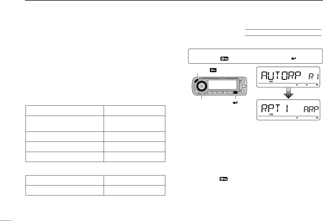
N Auto repeater USA/KOREAN versions only
The USA and Korean versions automatically use standard
repeater settings (duplex ON/OFF, duplex direction, tone encoder
ON/OFF) when the operating frequency falls within or outside
of the general repeater output frequency range. The offset
and repeater tone frequencies are not changed by the auto
repeater function. Reset these frequencies, if necessary.
D Frequency range and offset direction
• USA version
FREQUENCY RANGE SHIFT DIRECTION
147.000–147.395 MHz “DUP+” appears
442.000–444.995 MHz “DUP+” appears
447.000–449.995 MHz “DUP–” appears
145.200–145.495 MHz
146.610–146.995 MHz “DUP–” appears
• Korean version
FREQUENCY RANGE SHIFT DIRECTION
439.000–440.000 MHz “DUP–” appears
q
Enter “AUTORP” in FUNC set mode (SET).
MENU ¶ SET ¶ FUNC ¶ AUTORP
(p. 63)
(Push [MENU ]), (Rotate [DIAL], then push [ ](MONI).)
[DIAL]
[MENU ]
[ ]
w Rotate [DIAL] to select the auto repeater setting.
[USA version]:
• “RPT1” : Activates duplex only. (default)
• “RPT2” : Activates duplex and tone.
• “OFF” : Auto repeater function is turned OFF.
[Korean version]:
• “ON” : Activates duplex and tone. (default)
• “OFF” : Auto repeater function is turned OFF.
e Push [MENU ] to exit the set mode.
29
4
DV MODE PROGRAMMING
1
2
3
4
5
6
7
8
9
10
11
12
13
14
15
16
17
18
19
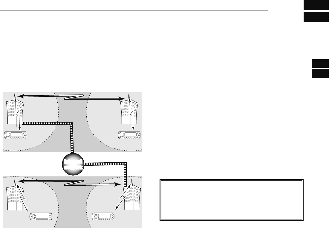
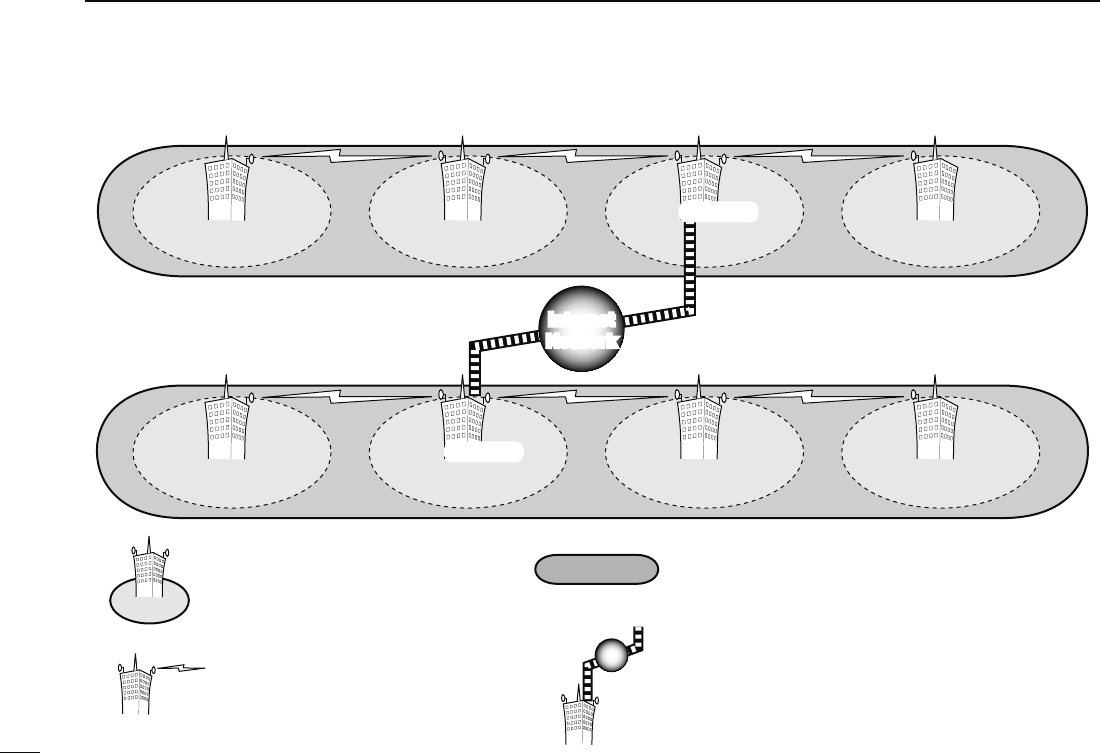
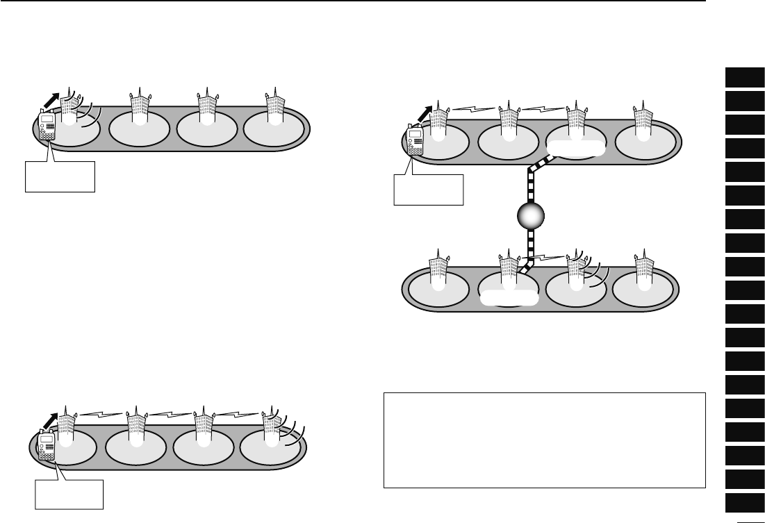
N About the D-STAR system
In the D-STAR (Digital Smart Technologies for Amateur
Radio) system, repeater linking via a 10 GHz backbone and/
or internet gateway provides you with much wider coverage
range during digital voice mode operation.
• D-STAR system outline
Station A
Station C Station D
Repeater A
Repeater D
440 MHz
440 MHz
Repeater C
10 GHz
Zone
Zone
Area
Station B
Repeater B
10 GHz
440 MHz
440 MHz
Internet
network
Internet
network
In traditional repeater operation, stations that are communi-
cating must both be in the repeater's operating area. However,
D-STAR repeaters can be linked via a 10 GHz backbone, as
shown in the illustration at left. Using D-STAR, stations A and
B can communicate even though they are in widely separated
repeater operating areas.
Furthermore, D-STAR repeaters can be linkled through an
internet gateway, which can extend the communication range
dramatically. For example, when station B uses the internet
gateway connection, it can communicate with station C even
though they are thousands of miles apart! By using the gate-
way connection, long distance communication is possible
using 144 or 440 MHz digital voice!
In the D-STAR system, an independent repeater’s operating
area is called an Area and a group that of linked repeaters
via a 10 GHz backbone is called a Zone.
About time-out timer function
The IC-880H has a time-out timer function for digital re-
peater operation. The timer limits a continuous transmis-
sion to approx. 10 min. Warning beeps will sound approx.
30 sec. before time-out and then again immediately before
time-out.
30
4DV MODE PROGRAMMING
Area 1
Zone A
Repeater 1
Area 2
Repeater 2
Area 3
Repeater 3
Area 4
Repeater 4
Zone B
Area 7
Repeater 6
Area 6
Repeater 7
Area 8
Repeater 8
Area 5
Repeater 5
Internet
Network
Internet
Network
(Gateway)
(Gateway)
Area:
The Area is the communication range
that is covered by a single repeater.
The repeater is called an area repeater
in the D-STAR system.
Zone:
The Zone is composed of several areas, that are linked
by a 10 GHz microwave link.
The areas 1 to 4 and 5 to 8 make up a zone at the
example above.
Link repeater:
The microwave (10 GHz) link repeater
provides to linking with another repeater
site (Area) for zone construction.
Gateway repeater:
Gateway repeaters provide communications between
different zones via the internet.
The repeater 3 and 6 are gateway repeaters at the
example above.
D System description
31
4
DV MODE PROGRAMMING
1
2
3
4
5
6
7
8
9
10
11
12
13
14
15
16
17
18
19
N Call sign programming
Four types of current call sign memory are available; “MY” (my
call sign=your own call sign) “UR” (your call sign=other sta-
tion call sign) “RPT1” (access repeater call sign) and “RPT2”
(link repeater call sign). Each call sign can be programmed
with up to 8 characters.
In addition, "MY" can store up to 6 call signs, and "UR" can
store up to 60 call signs in the call sign memory. Up to 300
repeater call signs can be stored in the repeater list.
D Your own call sign programming
Your own call sign must be programmed for both digital voice
and low-speed data communications (including GPS trans-
mission).
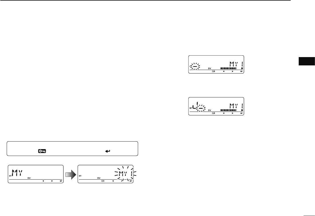
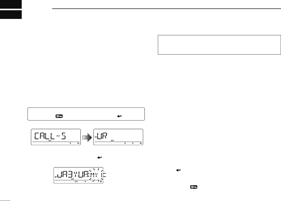
q Enter “MY” in call sign screen.
MENU ¶ CALL-S ¶ MY
(Push [MENU ]), (rotate [DIAL], then push [ ](MONI).)
• MY call sign screen is displayed.
w Rotate [DIAL] to select the desired call sign memory,
“MY1” to “MY6.”
e Push [](LOW) to enter call sign programming mode.
• The 1st digit blinks.
r Rotate [DIAL] to select the desired character or code.
• Push [](LOW) to move the cursor right; push [](CS) to move
the cursor left.
t Repeat the step r to enter your own call sign.
• Up to an 8 digit of call sign can be set.
• If an unwanted character is entered, push [](LOW) or [](CS)
to select the character, then push [CLR](DR) to erase the se-
lected character, or push and hold [CLR](DR) for 1 sec. to erase
all characters following the cursor.
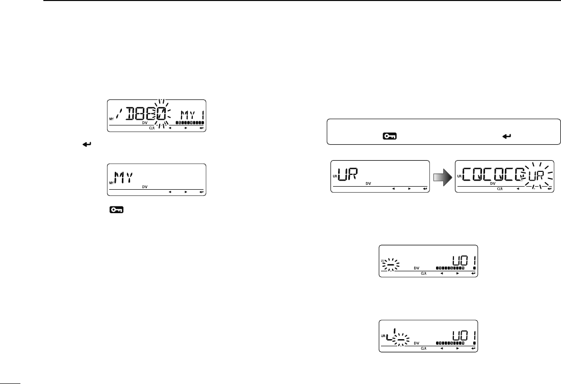
• To program a note (up to 4 characters, for operating radio type,
area, etc.), go to step y, otherwise go to step i.
y Push [](LOW) several times to set the cursor beside “/”
indication.
32
4DV MODE PROGRAMMING
u Repeat step r (at previous page) to program the desired
4 character note.
i Push [ ](MONI) to store the programmed call sign with
note and return to call sign screen.
o Push [MENU ] to return to frequency indication.
D Station call sign programming
Station call sign must be programmed to call a specific sta-
tion as well as for repeater operation in both digital voice and
low-speed data communications.
q Enter “UR” in call sign screen.
MENU ¶ CALL-S ¶ UR
(Push [MENU ]), (rotate [DIAL], then push [ ](MONI).)
• UR (Your) call sign screen is displayed.
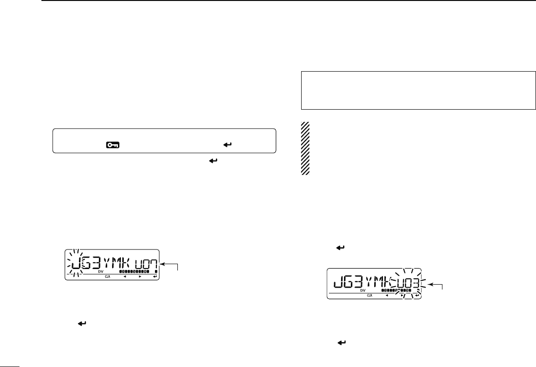
w Rotate [DIAL] to select the desired call sign memory,
“U01” to “U60.”
e Push [](LOW) to enter call sign programming mode.
• The 1st digit blinks.
r Rotate [DIAL] to select the desired character or code.
• Push [](LOW) or [](CS) to move the cursor right or left, re-
spectively.
33
4
DV MODE PROGRAMMING
1
2
3
4
5
6
7
8
9
10
11
12
13
14
15
16
17
18
19
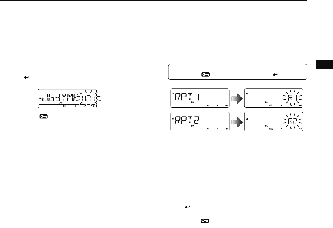
t Repeat the step r to enter the desired station call sign.
• Up to an 8 digit call sign can be set.
• If an unwanted character is entered, push [](LOW) or [](CS)
to select the character, then push [CLR](DR) to erase the se-
lected character, or push and hold [CLR](DR) for 1 sec. to erase
all characters following the cursor.
y Push [ ](MONI) to store the programmed call sign and
return to UR (Your) call sign screen.
u Push [MENU ] to return to frequency indication.
For your information
The ID-880H has a call sign edit record function.
When editing a call sign stored in a call sign memory (or reg-
ular memory/call channel), the default setting is to store the
edited call sign into blank channel automatically ("FULL" is
displayed when all call sign memory is programmed).
The edited call sign can be over-written when the setting of
the EDIT R (Edit record) is set to OFF or SEL. (p. 132)
However, you must manually over-write a reprogrammed call
sign in regular memory/call channels (temporary operation
without over-writing is possible).
D Current repeater call sign programming
“RPT1” or “RPT2” can store current call only, and repeater
call signs must be stored in the repeater list
(p. 39)
.
q Enter “RPT1” or “RPT2” in call sign screen.
MENU ¶ CALL-S ¶ RPT1 or RPT2
(Push [MENU ]), (rotate [DIAL], then push [ ](MONI).)
• RPT1/RPT2 call sign screen is displayed.
w Push [](LOW) to enter call sign programming mode.
• The 1st digit blinks.
e Rotate [DIAL] to select the desired character or code.
• Push [](LOW) or [](CS) to move the cursor right or left, re-
spectively.
r Repeat the step e to enter the desired repeater call sign.
• Up to an 8 digit call sign can be set.
• If an unwanted character is entered, push [](LOW) or [](CS)
to select the character, then push [CLR](DR) to erase the se-
lected character, or push and hold [CLR](DR) for 1 sec. to erase
all characters following the cursor.
t Push [ ](MONI) to store the programmed call sign and
returns to call sign screen.
y Push [MENU ] to return to frequency indication.
34
4DV MODE PROGRAMMING
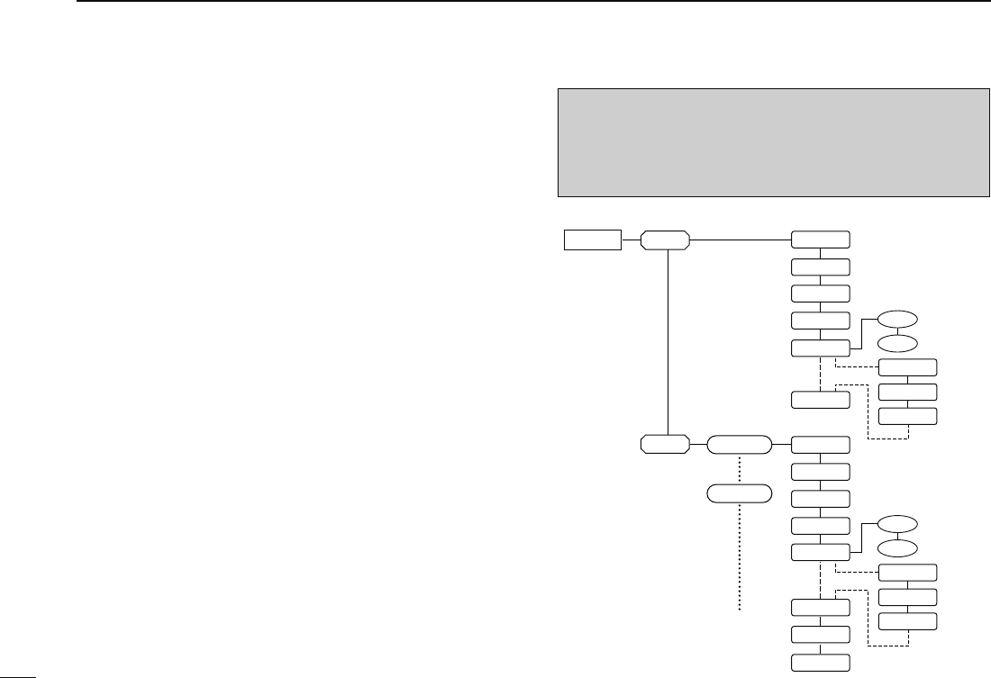
N Repeater list
The ID-880H can store up to 300 repeater call signs. The re-
peater list also stores the repeater name and access repeater
setting, etc.
The outline of repeater list is follows:
q Selection for new repeater program or changing a list
w Selection for a programmed repeater lists
e Repeater programming (Repeater name, Call sign,
Gateway repeater call sign, Repeater group, etc.)
r Access repeater programming (Down link frequency,
Duplex direction, Offset frequency)
D Repeater list contents
The following information can be programmed into repeater
lists:
R-NAME (Repeater name) (pgs. 40, 44)
CALL-S (Repeater call sign) (pgs. 40, 44)
GW CAL (Gateway repeater’s call sign) (pgs. 41, 45)
GROUP (Repeater group) (p. 41)
R1 USE (RPT1 use) (p. 42)
When R1 USE is selected YES, following contents appear.
FREQ (Repeater output frequency) (p. 42)
DUP (Duplex direction) (p. 43)
OFF SET (Offset frequency) (p. 43)
NOTE: Repeater lists can be erased by static electricity, elec-
tric transients, etc. In addition, they can be erased by mal-
function and during repairs. Therefore, we recommend that
memory data be written down or be saved to a PC using the
CS-80/880 CLONING SOFTWARE (free download).
RPT-L ADD-L
EDIT-L
NO
YES
YESNO
YESNO
FREQ
DUP
OFF
SET
R-NAME
R1 USE
CALL S
GW CAL
GROUP
ADD W
R-NAME
Rpeater 1
Rpeater 5
FREQ
DUP
OFF
SET
NO
YES
ADD W
OVR W
CLEAR
R1 USE
CALL S
GW CAL
GROUP
q
w
e
r
35
4
DV MODE PROGRAMMING
1
2
3
4
5
6
7
8
9
10
11
12
13
14
15
16
17
18
19
N
Repeater list programming
D New repeater list programming
q
Enter “ADD-L” in RPT-L menu.
MENU ¶ RPT-L ¶ ADD-L
(Push [MENU ]), (Rotate [DIAL], then push [ ](MONI).)
• “R-NAME” appears.
Repeater name programming (R-NAME)
w Push [](MONI) to enter the repeater name programming
state. See p. 44 for repeater name programming details.
• Repeater name programming screen is displayed.
e Program the repeater name, then push [ ](MONI) to exit
the state.
• Rotate [DIAL] to select the desired character, number, symbol
or space.
• Push [](LOW)/[](CS) to move the cursor right or left, respec-
tively.
r Rotate [DIAL] to select the next content (repeater call sign
programming).
Repeater call sign programming (CALL S)
t Push [](MONI) to enter the repeater call sign program-
ming state. See p. 44 for repeater call sign programming
details.
• Repeater call sign programming screen is displayed.
y Program the repeater call sign, then push [ ](MONI) to
exit the state.
• Rotate [DIAL] to select the desired character, number, symbol
(‘/’only) or space.
• Push [](LOW)/[](CS) to move the cursor right or left, respec-
tively.
u Rotate [DIAL] to select the next content (gateway repeater
call sign programming).
CONVENIENT!
After you program the repeater call sign, you can skip the
other programming and store the list.
± Push and hold [S.MW](M/CALL) for 1 sec. to enter mem-
ory write state, then push [](MONI) to store the list.
36
4DV MODE PROGRAMMING
Gateway repeater call sign programming (GW CAL)
i Push [](MONI) to enter the gateway repeater call sign
programming state. See p. 45 for gateway repeater call
sign programming details.
• Gateway repeater call sign programming screen is displayed.
• Programmed repeater call sign is displayed and the 8th digit is
automatically added or replaced to “G.”
o When the programmed repeater has gateway capability,
push [](MONI) to exit gateway repeater setting and skip
to !2. Or when the programmed repeater has a different
repeater for gateway communication, follow the next step
!0.
• When the repeater does not have a gateway repeater, follow the
next step !0, too.
!0 Program the other gateway repeater call sign, then push
[](MONI) to exit the state.
• Rotate [DIAL] to select the desired character, number, symbol
(‘/’only) or space.
• Push [](LOW)/[](CS) to move the cursor right or left, respec-
tively.
• Up to an 8 digit call sign can be set, but 8th digit must be set
to “G.”
• When the repeater does not have a gateway repeater, push and
hold [CLR](DR) for 1 sec. to erase all characters.
!1 Rotate [DIAL] to select the next content (repeater group
programming).
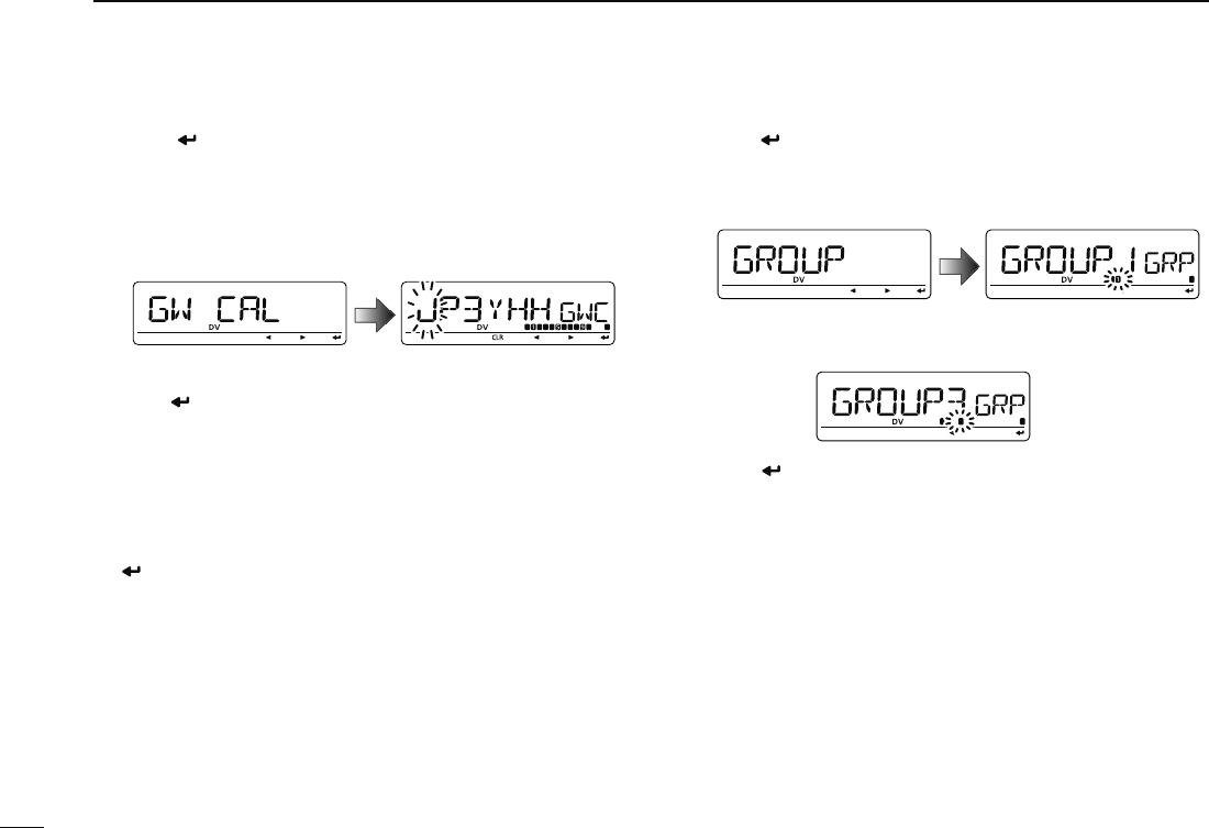
Repeater group programming (GROUP)
!2 Push [](MONI) to enter the repeater group programming
state.
• Repeater group programming screen is displayed.
• Selected group number appears and group indicator blinks.
!3
Rotate [DIAL] to
select the desired repeater group.
• Selected group number appears and group indicator blinks.
!4 Push [ ](MONI) to set the repeater group and exit the
state.
!5 Rotate [DIAL] to select the next content (access repeater
setting).
37
4
DV MODE PROGRAMMING
1
2
3
4
5
6
7
8
9
10
11
12
13
14
15
16
17
18
19
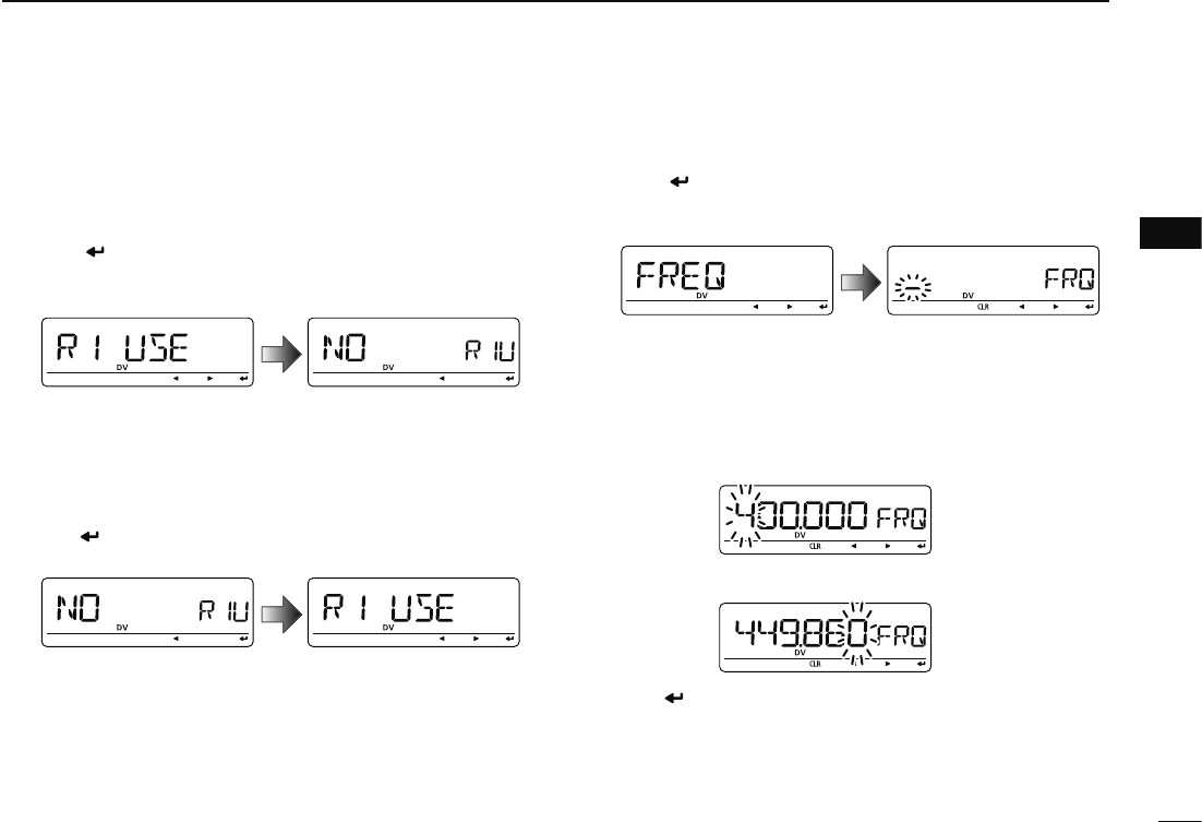
Access repeater setting (RPT 1 U)
The programmed repeater lists are assigned to use for the
access repeater (RPT1) or no in DR mode. To use for RPT1,
repeater frequency, duplex direction and offset frequency
must be programmed.
!6 Push [ ](MONI) to enter the access repeater program-
ming state.
• Access repeater programming screen is displayed.
!7 Rotate [DIAL] to select “YES” or “NO.”
• When “NO” is selected, the repeater can be selected as the link
repeater (RPT2) only in DR mode.
• When “YES” is selected, the repeater can be selected as the ac-
cess repeater (RPT1) and link repeater (RPT2) in DR mode.
!8 Push [ ](MONI) to exit the state.
± When “NO” is selected at step !7, skip to step #1.
± When “YES” is selected at step !7, push [](2) or [](8)
to select the access repeater (RPT1) programming.
Follow the next step !9 to program the repeater.
Frequency programming (FREQ)
This content appears when R1 USE is selected YES.
!9 Push [ ](MONI) to enter the frequency programming
state.
• Frequency programming screen is displayed.
@0 Rotate [DIAL] to select the frequency band.
• The selected number blinks at 1st digit.
• Push [](LOW) to move the cursor right; push [](CS) to move
the cursor left.
• Push and hold [CLR](DR) for 1 sec. to clear the displayed fre-
quency.
@1 Repeat step @0 until the repeater frequency is set.
@2 Push [ ](MONI) to set the frequency and exit the state.
@3 Rotate [DIAL] to select the next content (duplex direction
programming).
38
4DV MODE PROGRAMMING
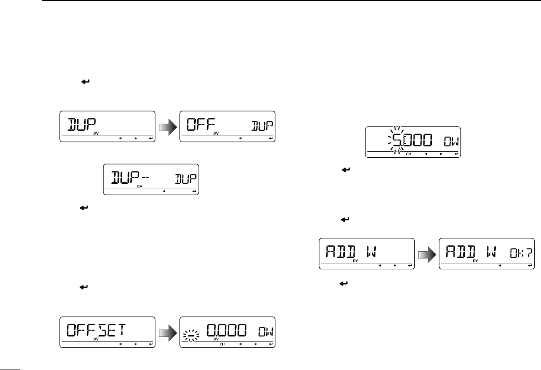
Duplex direction setting (DUP)
This content appears when R1 USE is selected YES.
@4 Push [ ](MONI) to enter the duplex direction setting
state.
• Duplex direction setting screen is displayed.
@5 Rotate [DIAL] to select the duplex direction.
@6 Push [ ](MONI) to set the duplex direction and exit the
state.
@7 Rotate [DIAL] to select the next content (offset frequency
programming).
Offset frequency programming (OFF SET)
This content appears when RPT1 U is selected YES.
@8 Push [ ](MONI) to enter the offset frequency program-
ming state.
• Offset frequency programming screen is displayed.
@9 Rotate [DIAL] to select the offset frequency.
• The selected number blinks.
• Push [](LOW) to move the cursor right; push [](CS) to move
the cursor left.
• Push and hold [CLR](DR) for 1 sec. to clear the displayed fre-
quency.
#0 Push [ ](MONI) to set the offset frequency and exit the
state.
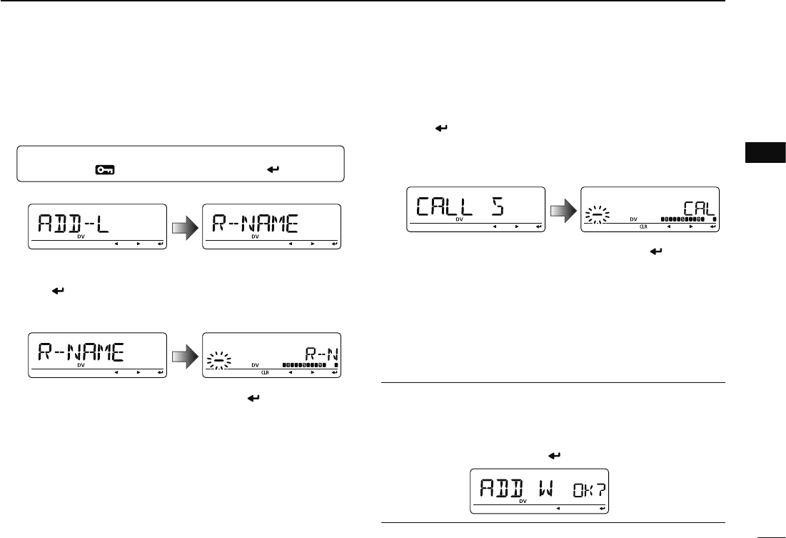
Storing the repeater list (ADD W)
#1 Rotate [DIAL] to select the store operation.
#2 Push [](MONI) to enter storing state.
• “ADD W OK?” appears.
#3 Push [ ](MONI) again to store the list.
39
4
DV MODE PROGRAMMING
1
2
3
4
5
6
7
8
9
10
11
12
13
14
15
16
17
18
19
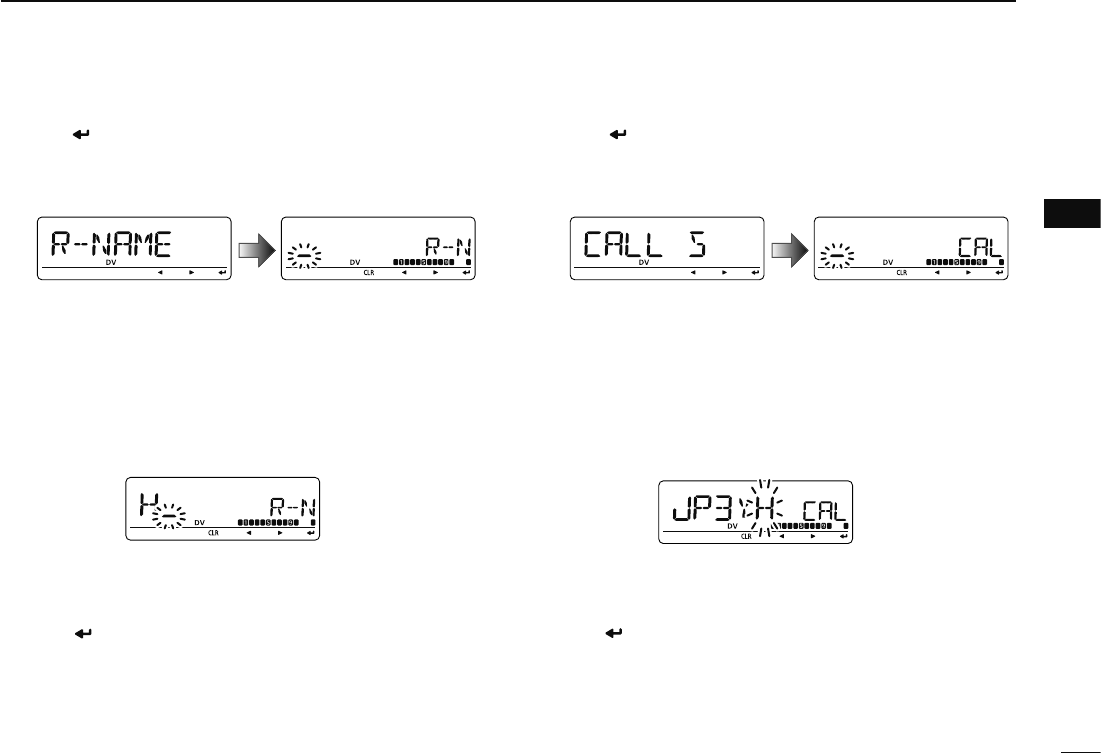
Repeater name programming (R-NAME)
q Push [ ](MONI) to enter the repeater name programming
state.
• Repeater name programming screen is displayed.
• The 1st digit blinks.
w Rotate [DIAL] to select the desired character, number,
symbol or space.
• The selected character blinks.
• Push [](LOW) to move the cursor right; push [](CS) to move
the cursor left.
• Push [CLR](DR) to erase the selected character, or push and
hold [CLR](DR) for 1 sec. to erase all characters following the
cursor.
e Repeat step w until the desired repeater name is pro-
grammed.
• Up to an 8 digit name can be set.
r Push [ ](MONI) to program the repeater name and exit
the state.
Repeater call sign programming (CALL S)
q Push [ ](MONI) to enter the repeater call sign program-
ming state.
• Repeater call sign programming screen is displayed.
• The 1st digit blinks.
w Rotate [DIAL] to select the desired character, number or
symbol (‘/’ only).
• The selected character blinks.
• Push [](LOW) to move the cursor right; push [](CS) to move
the cursor left.
• Push [CLR](DR) to erase the selected character, or push and
hold [CLR](DR) for 1 sec. to erase all characters following the
cursor.
e Repeat step w until the desired repeater call sign is pro-
grammed.
• Up to an 8 digit call sign can be set.
r Push [ ](MONI) to program the repeater call sign and exit
the state.
40
4DV MODE PROGRAMMING
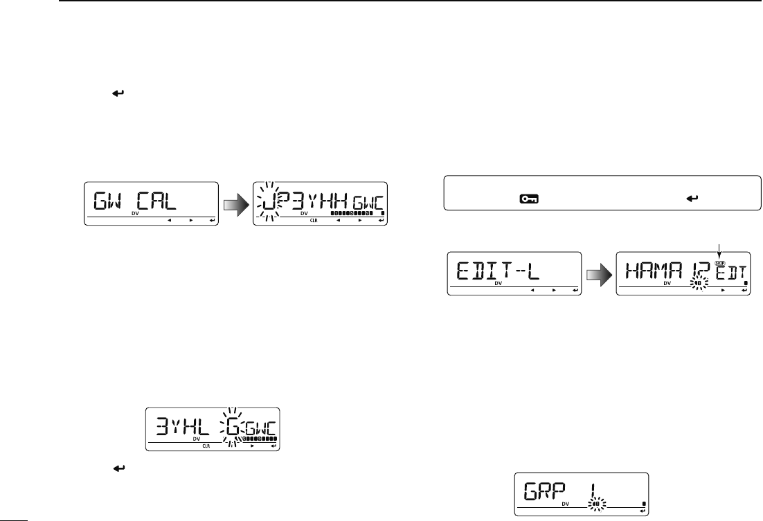
Gateway repeater call sign programming (GW CALL)
q Push [ ](MONI) to enter the gateway repeater call sign
programming.
• Gateway repeater call sign programming screen is displayed.
• Programmed repeater call sign is displayed, then the 1st char-
acter blinks.
• The 8th digit is automatically added or replaced to “G.”
w Rotate [DIAL] to select the desired character, number,
symbol (‘/’ only) or space.
• The selected character blinks.
• Push [](LOW) to move the cursor right; push [](CS) to move
the cursor left.
• Push [CLR](DR) to erase the selected character, or push and
hold [CLR](DR) for 1 sec. to erase all characters following the
cursor.
e Repeat step w until the desired repeater call sign is pro-
grammed.
• Up to an 8 digit call sign can be set, but 8th digit must be set to “G.”
r Push [ ](MONI) to program the gateway repeater call
sign and exit the state.
N
Changing a repeater list
This function re-programs a repeater list’s contents. This is
useful when already programmed contents are mistaken or
some contents are added to the list.
q
Enter “EDIT-L” in RPT-L menu.
MENU ¶ RPT-L ¶ EDIT-L
(Push [MENU ]), (Rotate [DIAL], then push [ ](MONI).)
• Programmed repeater name appears.
SKIP indicator
SKIP indicator shows the selected repeater can not be used
for access repeater (RPT1) in DR mode as follow reasons.
• “R1 USE” is set to “NO”
• Either “FREQ” (frequency) or “DUP” (duplex direction)
has not been programmed
w Push and hold [BAND] for 1 sec. to enter group selection,
rotate [DIAL] to select the desired group (0–9), then push
[BAND].
41
4
DV MODE PROGRAMMING
1
2
3
4
5
6
7
8
9
10
11
12
13
14
15
16
17
18
19
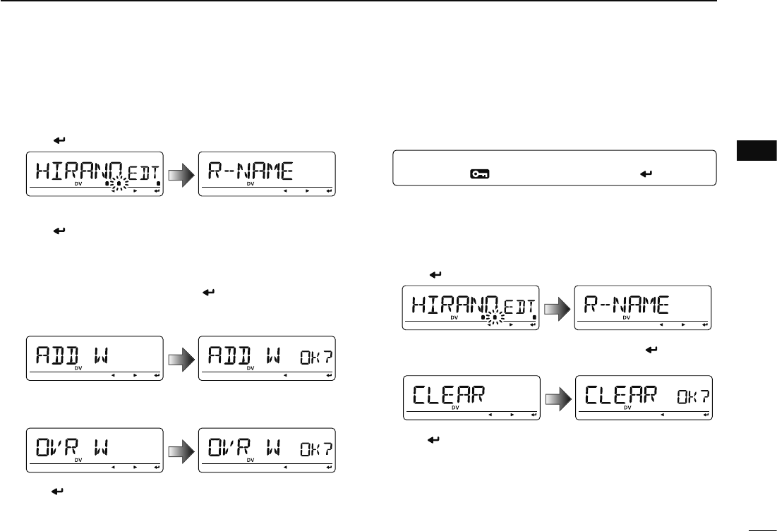
e Rotate [DIAL] to select the desired repeater list to be
changed.
r Push [](MONI) to enter the list.
t Rotate [DIAL] to select the content to be changed, then
push [](MONI) to enter the content and reprogram the
content (see pages 40–43 for new repeater list program-
ming details).
y After programming is finished, rotate [DIAL] to select
“ADD W” or “OVR W,” then push [](MONI).
When “ADD W” is selected;
• “ADD W OK?” appears.
When “OVR W” is selected;
• “OVR W OK?” appears.
u Push [ ](MONI) again to store the list.
N
Clearing a repeater list
Contents of programmed list can be cleared (erased)
.
q
Enter “EDIT-L” in RPT-L menu.
MENU ¶ RPT-L ¶ EDIT-L
(Push [MENU ]), (Rotate [DIAL], then push [ ](MONI).)
• Programmed repeater name appears.
w Rotate [DIAL] to select the desired repeater list to be
erased.
• Push and hold [BAND] for 1 sec. to enter group selection, rotate
[DIAL] to select the desired group (0–9) then push [BAND].
e Push [ ](MONI) to enter the list.
r Rotate [DIAL] to select “CLEAR,” then push [ ](MONI).
• “CLEAR OK?” appears.
t Push [ ](MONI) again to clear the list.
42
DV MODE OPERATION
5
N Digital mode operation
The ID-880H can be operated in digital voice mode and low-
speed data operation for both transmit and receive. It can
also be connected to a GPS receiver (compatible with an RS-
232 output/NMEA format/4800 bps/9600 bps) to transmit/receive
position data.
N Current call sign setting
Set the current call sign for DV operation as follows.
q Enter “CALL-S” in MENU screen.
MENU ¶ CALL-S
(Push [MENU ]), (Rotate [DIAL], then push [ ](MONI).)
• Call sign screen is displayed.
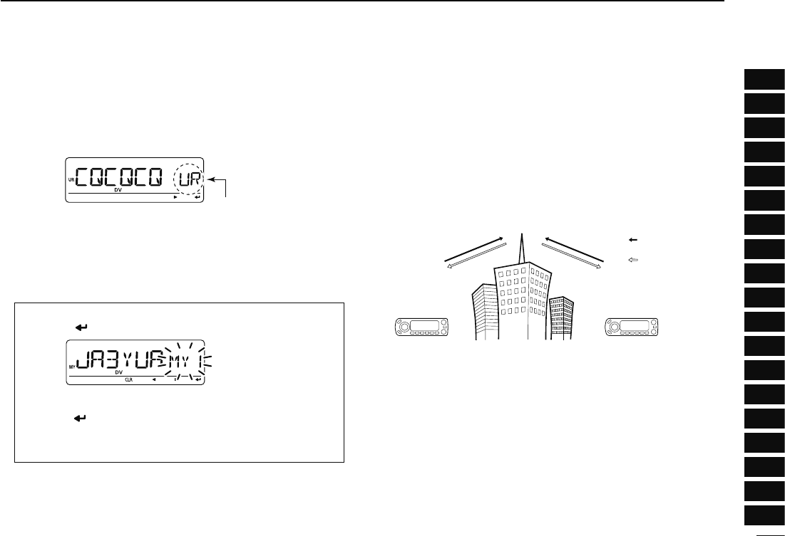
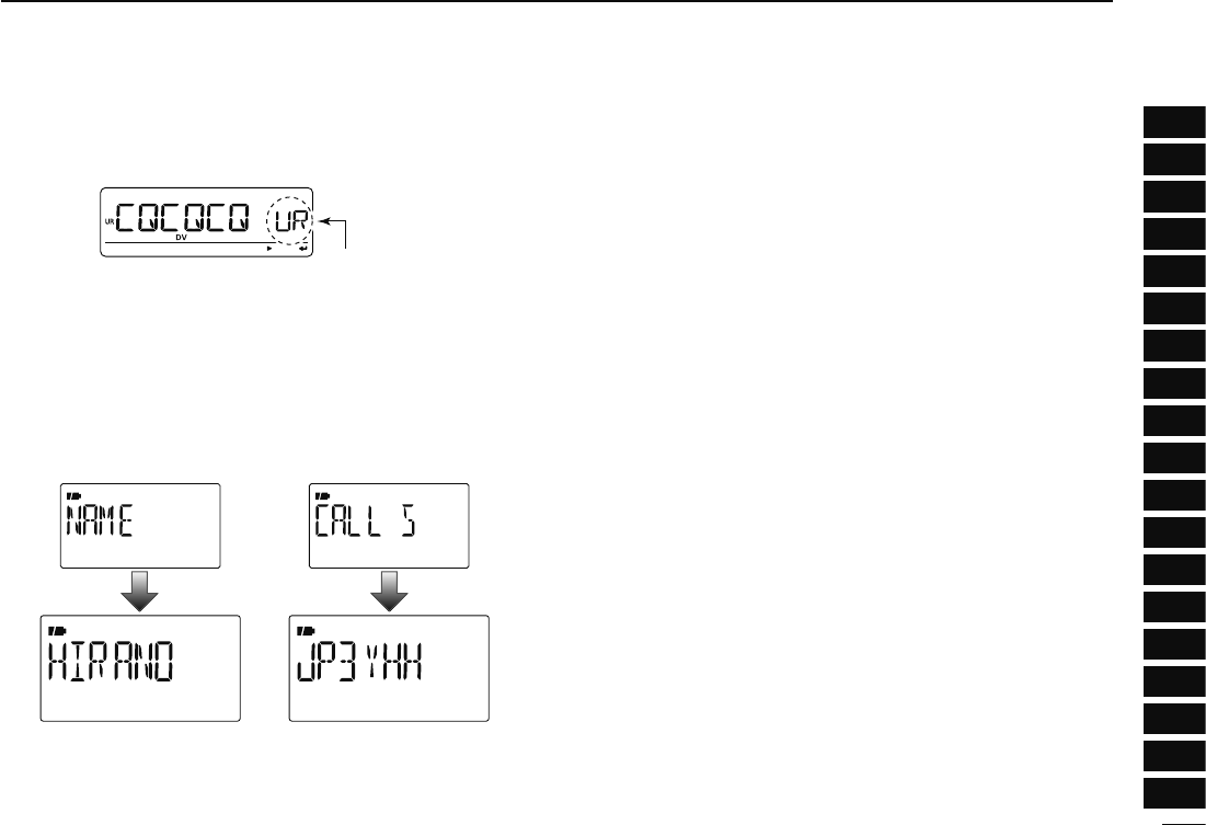
w Rotate [DIAL] to select the desired call sign group, “UR,”
RPT1,” “RPT2” or “MY,” then push [](MONI).
• Current call sign is displayed.
Quick entry
Push [CS] to enter the current call sign mode. See next
page for details.
• Call sign group
UR : Station call signs (U01–U60), “CQCQCQ” (U--) or
repeater CQ* (R-L) can be selected.
* ‘/’ plus repeater call sign (R-L), ‘/’ stands for “CQCQCQ”
RPT1 : “NOTUSE”* (R--) or repeater call signs (R-L) can be
selected.
* Direct communication (NOT USE repeater)
RPT2 : “NOTUSE”* (R--) or repeater call signs (R-L) can be
selected.
* Direct communication or using area repeater only (NOT
USE link repeater)
MY : My call signs (MY1–MY6) can be selected.
e Rotate [DIAL] to select the desired call sign.
Or push [](LOW) to enter the current call sign program-
ming state (pgs. 36–38).
• When “UR,” “RPT1” or “RPT2” is selected at step w, push
[BAND] several times to select the repeater call sign groups.
• When “RPT1” or “RPT2” is selected at step w, push [M/CALL]
to toggle the call sign and repeater name indications.
r Push [ ](MONI) to set the selected call sign to the current
call sign and exit the state.
t Repeat steps w to r to set the other current call sign.
y Push [MENU ] to return to frequency indication.
43
5
DV MODE OPERATION
1
2
3
4
5
6
7
8
9
10
11
12
13
14
15
16
17
18
19
D Confirming current call sign
q Push [CS] to enter the current call sign mode.
• Current UR (your) call sign is displayed.
Appears momentarily
w Rotate [DIAL] to select and confirm the other current call
sign.
• (“UR”), “R1,” “R2” and “MY” appears in sequence.
• When “R1” or “R2” is selected, push and hold [M/CALL] for 1
sec. to toggle the call sign and repeater name indications.
When changing the call sign
q Push [ ](5) to enter the call sign selection mode.
w Rotate [DIAL] to select the desired call sign, then
push [](5).
• When “UR,” “R1” or “R2” is selected, push [BAND] several
times to select the repeater call sign groups.
e Push [CS] again to return to frequency indication.
N Receiving a D-STAR repeater
When the ID-880H receives a signal from a D-STAR repeater,
it receives four call sign: caller’s call sign, called call sign,
repeater call sign 1 (the repeater that caller accessed), and
repeater call sign 2 (the liked repeater). You can copy the re-
ceived call signs to current call signs, and you can also reply
to a call.
Station A Station B
Repeater
449.700 MHz
444.700 MHz 444.700 MHz
449.700 MHz
Uplink
Downlink
(transmitting freq.)
(receiving freq.)
• Presetting
q Set the desired repeater frequency. (p. 23)
• Select output power, if desired. (p. 27)
w Set the shift direction of the transmit frequency. (DUP– or
DUP; see p. 31 for details.)
• When the auto repeater function is in use (U.S.A. and Korean
versions only), this selection is not necessary. (p. 32)
e Select DV mode. (p. 25)
r When signal is received, display indicates received call
sign.
See next page for information about received call signs.
44
5DV MODE OPERATION
N Received call sign
When a call is received in DV mode, the calling station and
the repeater call signs being used can be stored into the re-
ceived call record. The stored call signs are viewable in the
following manner. Up to 20 calls can be recorded.
D Desired call record indication
q Enter RX call sign set mode.
MENU ¶ RX-CAL
(Push [MENU ]), (Rotate [DIAL], then push [ ](MONI).)
• RX call sign screen is displayed.
w Rotate [DIAL] to select the desired record channel.
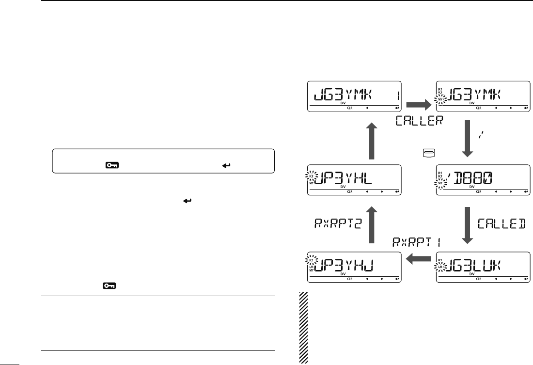
e To confirm the received call, push [ ](MONI) several times
to select the desired call sign from CALLER, / (CALLER’s
note), CALLED, RXRPT1 and RXRPT2.
CALLER : The station call sign that made a call.
/ : 4 character note with call sign that made a call.
CALLED : The station call sign called by the caller.
RXRPT1 : The repeater call sign used by the caller station.
RXRPT2 : The repeater call sign linked from RXRPT1.
r Push [MENU ] to return to frequency indication.
For your information
When receiving a call, the received station call sign is auto-
matically displayed and scrolled in sequence at the frequency
display.
This can be turned OFF in DISP set mode. (p.132)
Push
Call record channel
MONI
NOTE: When a call is received in DV mode when the
power save function is activated, the call sign may not be
received correctly.
This is normal, not a malfunction, because the call sign
information cannot be detected during power save.
Turn the power save function OFF (p. 123) if you want to
receive a call sign correctly even in stand-by operation.
45
5
DV MODE OPERATION
1
2
3
4
5
6
7
8
9
10
11
12
13
14
15
16
17
18
19
D One-touch reply using the call record
The stored call signs in the call record can be used to call the
other station.
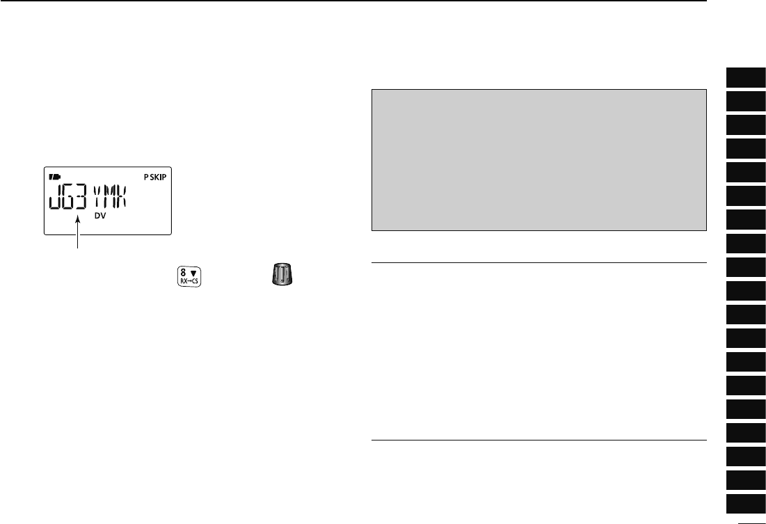
q After receiving a call, push and hold [RX©CS](CS) for
1 sec.
The received call sign is displayed
while pushing and holding with rotating .
• Set your own call sign (MY) in advance. (pgs. 36, 47, 48)
• The call sign in “CALLER” is stored as “UR,” “RXRPT1” is stored
as “R2” and “RXRPT2” is stored as “R1.”
• Error beeps sound when a call sign is received incorrectly, and
no call sign is set in this case.
w Push [PTT] to transmit; release to receive.
Important!
Setting call signs with the “One-touch reply using the call
record” operation as at left are for temporary operation
only. Therefore, the set call signs will be over-written when
another call record is used to set call signs.
• Never saved into a call sign memory.
If you want to save the set call signs, see “Copying the call
record contents into call sign memory” (p. 51) for details.
For your information
When a call specifying your call sign is received, the call
signs of the calling station and the repeater it is using can be
automatically used for operation.
• When “CALL W (RX call sign auto write)” (p. 131) is set to
“AUTO,” the station call sign in “CALLER” is set to “UR” au-
tomatically.
• When “RPT W (Repeater call sign auto write)” (p. 131) is set
to “AUTO,” the repeater call sign in “RXRPT1” is stored as
“R2” and “RXRPT2” is stored as “R1” automatically.
46
5DV MODE OPERATION
N Copying the call sign
D Copying the call sign memory contents
This function is convenient when or modifying a part of the
current call sign.
q During DV mode operation, enter call sign menu.
MENU ¶ CALL-S
(Push [MENU ]), (Rotate [DIAL], then push [ ](MONI).)
w Rotate [DIAL] to select “UR,” then push [ ](MONI).
e Rotate [DIAL] to select the desired call sign channel to be
copied.
• U01–U60 are available.
• When “AUTO” is set to “EDIT R” item
r Push [](LOW) to select the call sign programming mode.
• The 1st digit of the selected call sign blinks.
Blank channel is selected
automatically.
t Modify the selected call sign as described in “Station call
sign programming” (p. 37).
y Push [](MONI) to store the modified call sign into the
selected blank channel.
NOTE:
Make sure that the “EDIT R (EDIT RECORD)” item in DV
set mode is set to “AUTO” or “SEL” in advance. (p. 132)
NOTE: The message “FULL” is displayed when no blank
channel is available in station call sign memory.
In this case, select the desired call sign channel number
as described in step u is set to “• When “SEL” is set to
“EDIT R” item below.
• When “SEL” is set to “EDIT R” item
r Push [](LOW) to select the call sign programming mode.
• The 1st digit of the selected call sign blinks.
t Modify the selected call sign as described in “Station call
sign programming” (p. 37).
y Push [ ](MONI).
• Call sign channel number blinks.
Call sign channel number
blinks.
u Rotate [DIAL] to select the desired call sign channel to
store.
i Push [](MONI) to store the modified call sign into the
selected channel.
47
5
DV MODE OPERATION
1
2
3
4
5
6
7
8
9
10
11
12
13
14
15
16
17
18
19
D Copying the call record contents into call sign memory
This is a way to copy the call record contents (“CALLER,”
“RXRPT1” and “RXRPT2”) into call sign memory (“UR,” “R1” and
“R2”) at the same time or individually.
q Enter RX CAL (RX call sign) mode.
MENU ¶ RX CAL
(Push [MENU ]), (Rotate [DIAL], then push [ ](MONI).)
• RX call sign screen is displayed.
w Rotate [DIAL] to select the desired record channel.
e Push [](MONI) several times to select the desired call
sign from CALLER, / (CALLER’s note), CALLED, RXRPT1
and RXRPT2.
CALLER : The station call sign that made a call.
/ : 4 character note with call sign that made a call.
CALLED : The station call sign called by the caller.
RXRPT1 : The repeater call sign used by the caller station.
RXRPT2 : The repeater call sign linked from RXRPT1.
r Push [](LOW) to enter copy select mode.
• Copy select screen is displayed.
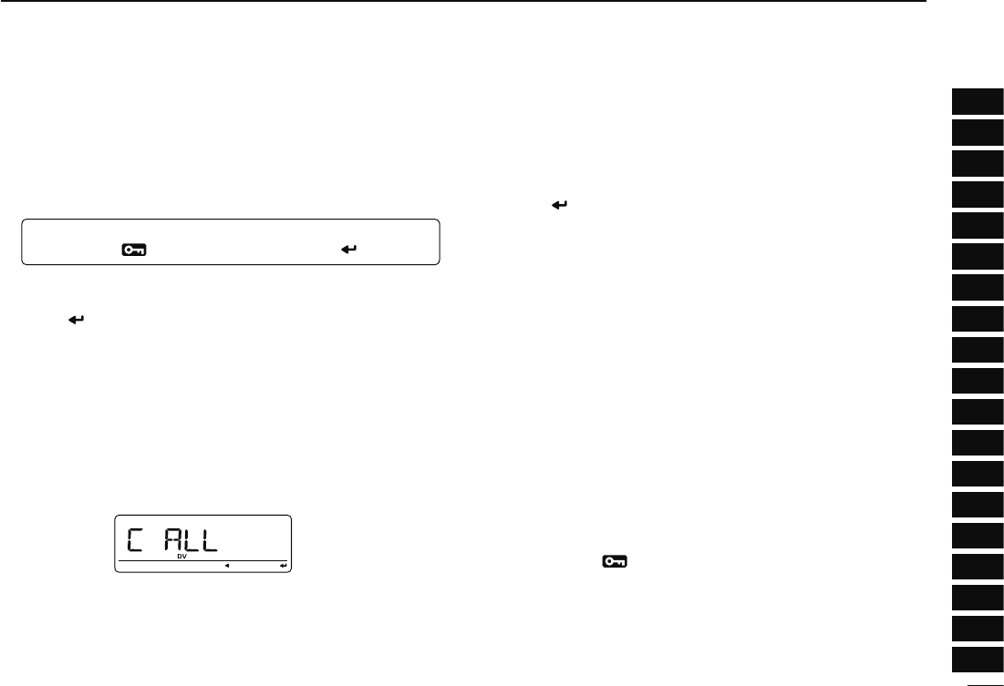
t Rotate [DIAL] to select the desired call sign to be copied
from “C ALL,” “C UR01”–“C UR60,” “C R-L” and “CLEAR.”
• “C ALL” selection won’t appear when either station call sign
memory or repeater list has no blank channel.
y Push [ ](LOW) to copy the selected record’s contents into
the appropriate call sign memory or repeater lists.
C ALL : Copy the caller call sign in “CALLER” to “UR” (sta-
tion call sign memory) and the repeater call sign
in “RXRPT1” / “RXRPT2” to the repeater lists. This
selection won’t appear when either station call sign
memory or repeater list has no blank channel.
C UR01– :
C UR60 : Copy the caller call sign in “CALLER” to “UR” (sta-
tion call sign memory). This selection appears
when entering the copy select mode (step r) from
“CALLER” only.
C R-L : Copy the repeater call sign in “RXRPT1” / “RXRPT2”
to the repeater lists. This selection appears when
entering the copy select mode (step r) from
“RXRPT1” or “RXRPT2” only.
CLEAR : Clear (erase) the selected call record contents.
u Push [MENU ] to return to frequency indication.
48
5DV MODE OPERATION
N DR (D-STAR Repeater) mode operation
DR (D-STAR Repeater) mode is used for D-STAR repeater
operation. In this mode, you can select the pre-programmed
repeaters and UR (your) call sign by using [DIAL].
• DR mode operation flow chart
Step 3: (RPT2 selection)
Select link repeater, gateway repeater
or access repeater only (NOT USE).
Push PTT to transmit, release to receive.
Step 1: (RPT1 selection)
Select the access repeater.
- Access repeater scan is useful to find a repeater.
Step 2: (UR call sign selection)
Select UR call sign.
Calling a CQ
In same area: CQCQCQ
To other area: Repeater name
In same area: NOT USE
In same zone: Repeater name
To different zone: GW
Calling a specific station
• Repeater settings can be stored into a memory channel.
D Access repeater scan
q Push [DR] to select DR mode.
• DV mode is selected automatically.
w Push and hold [SCAN](VFO/MHz) for 1 sec. to start the
scan.
• Scan pauses when a signal is received.
• Rotate [DIAL] to change the scanning direction, or resumes
manually.
• Push [V/MHz] to stop the scan.
[SCAN]
During access repeater scan
49
5
DV MODE OPERATION
1
2
3
4
5
6
7
8
9
10
11
12
13
14
15
16
17
18
19
• Skip setting
Unwanted access repeater can be skipped for rapid selection
or scan.
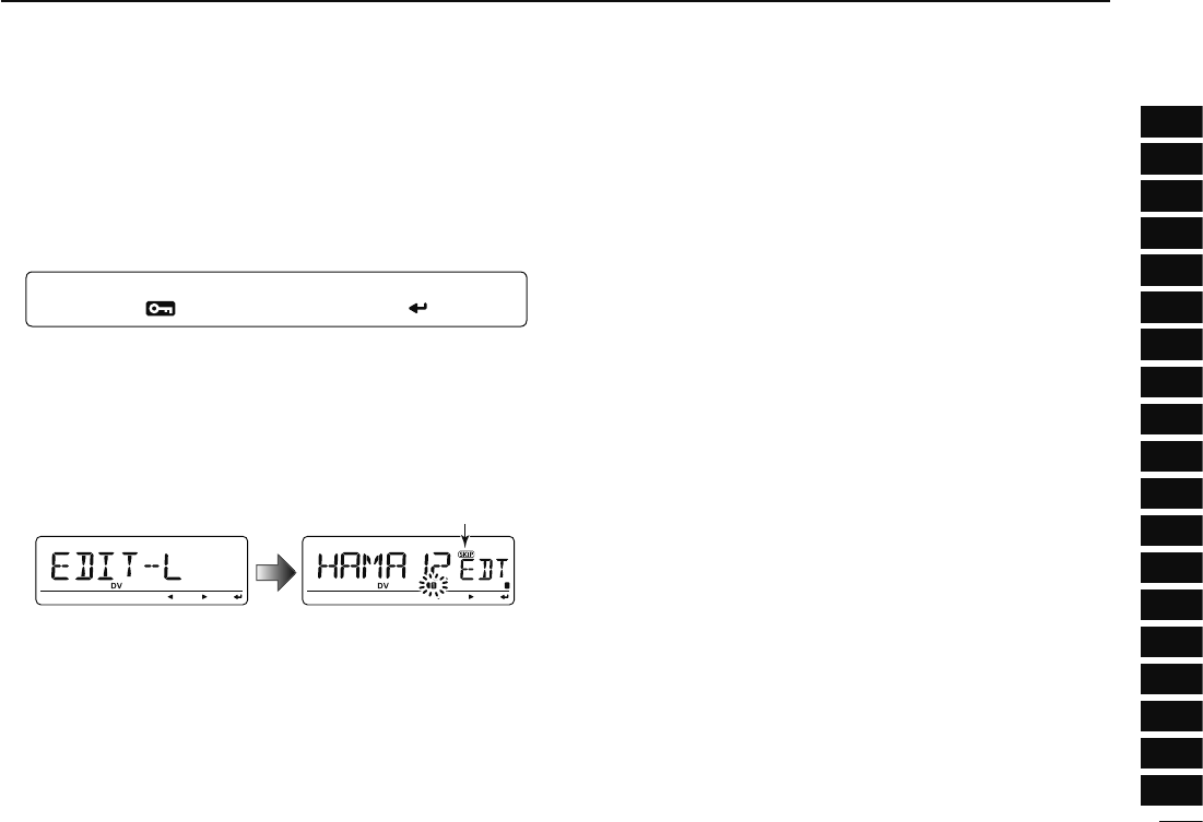
q
Enter “EDIT-L” in RPT-L menu.
MENU ¶ RPT-L ¶ EDIT-L
(Push [MENU ]), (Rotate [DIAL], then push [ ](MONI).)
• Programmed repeater name appears.
w Rotate [DIAL] to select the desired access repeater to be
skipped.
• Push and hold [BAND] for 1 sec. to enter group selection, rotate
[DIAL] to select the desired group (0–9) then push [BAND].
e Push [DR] to toggle the skip setting ON and OFF.
• “SKIP” appears when the channel is set as skip channel.
SKIP indicator
SKIP indicator shows the selected repeater can not be used
for access repeater (RPT1) in DR mode as follow reasons.
• “R1 USE” is set to “NO”
• Either “FREQ” (frequency) or “DUP” (duplex direction)
has not been programmed
50
5DV MODE OPERATION
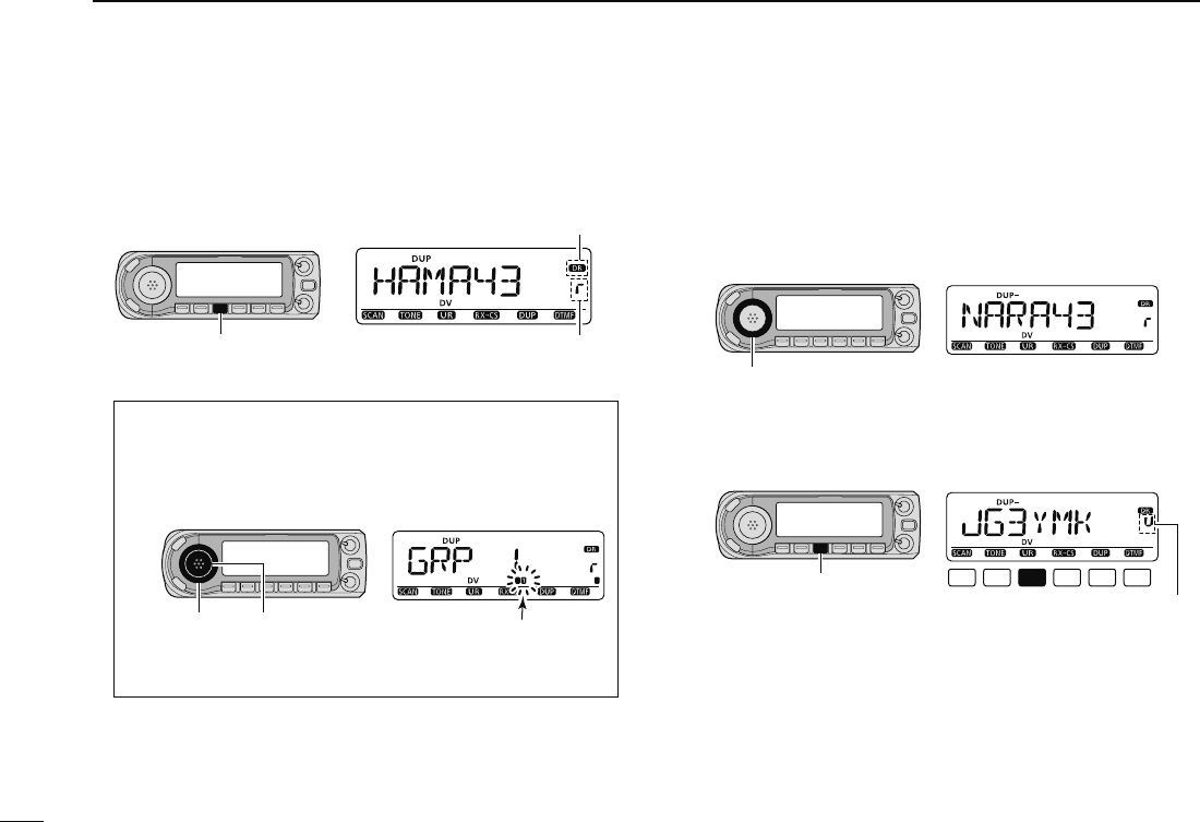
N Calling CQ
STEP 1 (RPT1 selection)
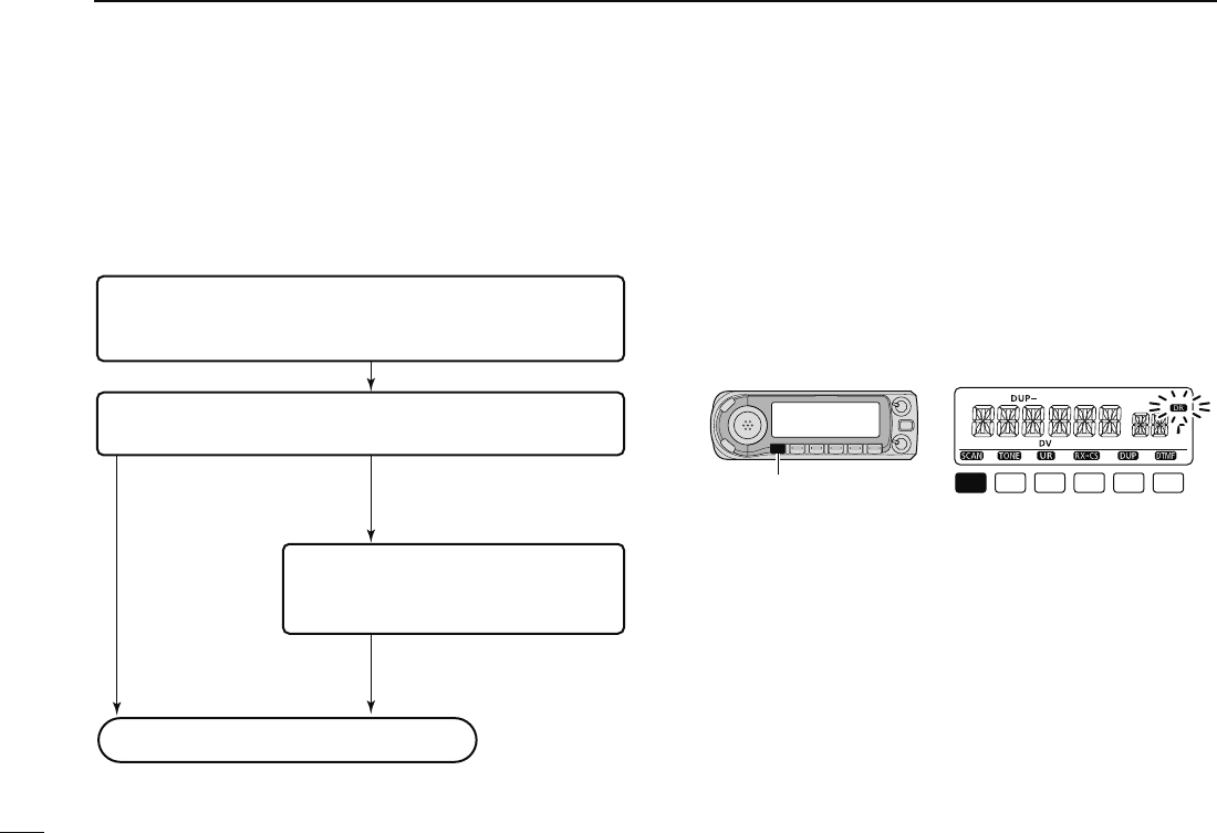
q Push [DR] to enter DR mode.
[DR]
Appears
Repeater selection indicator
w Select the repeater group.
Selecting the repeater group
q Push and hold [BAND] for 1 sec., then rotate [DIAL]
to select the desired repeater group.
• Only assigned groups from GRP 1–GRP 9 and GRP 0 are
selectable.
[DIAL] [BAND] Group indicator blinks
w Push [BAND] again to release the group selection.
e Rotate [DIAL] to select the access repeater.
• Only repeaters that have access repeater settings programmed
are selectable.
• Group indicator appears momentarily when rotating [DIAL].
• Access repeater scan can be used for the selection. (p. 48)
[DIAL]
STEP 2 (UR call sign selection)
r Push and hold [UR](DR) for 1 sec. to enter the your call
sign selection.
[UR]
UR selection indicator
t Select the group as step w.
• Only assigned GRP 1–GRP 9, GRP 0, GRP UR and GRP CQ
are selectable.
• UR (your) call signs are selectable in GRP UR.
• “CQCQCQ” is selectable in GRP CQ.
• Push [BAND] several times to select “GRP UR,” “GRP CQ” and
“GRP RP.”
51
5
DV MODE OPERATION
1
2
3
4
5
6
7
8
9
10
11
12
13
14
15
16
17
18
19
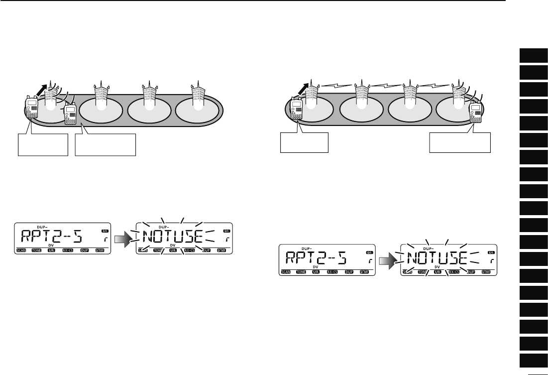
D Calling CQ in the same area (Area CQ)
My call sign:
JA3YUA
CQ
Area
Zone
Repeater q: NARA43 (JP3YHL)
q w e r
Continued instruction from step t on page 54.
y Push [BAND] several times to select “GRP CQ,” then
“CQCQCQ” is selected as UR (your) call sign automati-
cally.
• The link repeater (RPT2) setting is set to “NOT USE” automati-
cally.
u Push [PTT] to transmit; release to receive.
D Calling CQ in another area
(Zone CQ/Different zone CQ)
• Calling CQ in the same zone (Zone CQ)
My call sign:
JA3YUA
Repeater q : NARA43 (JP3YHL)
Repeater r : IKOMA43 (JP3YHJ)
CQ
q w e r
Area
Zone
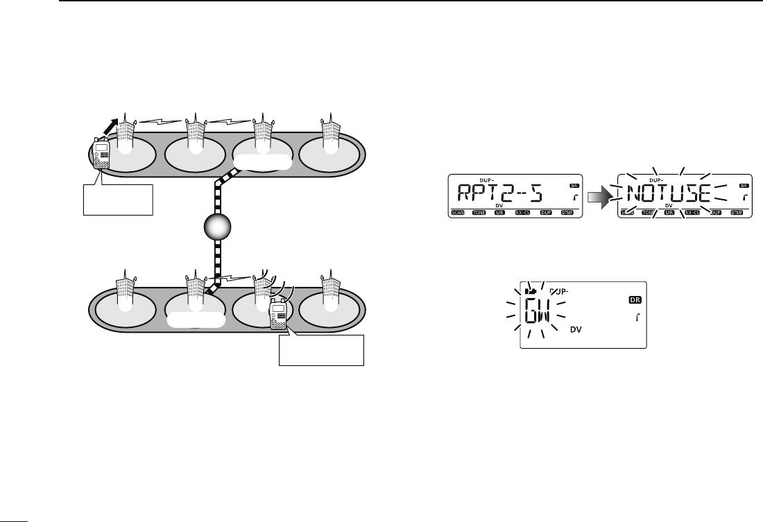
• Calling CQ in another zone (Different zone CQ)
Repeater q :
Repeater e :
Repeater u :
CQ
q w e r
t y u i
My call sign:
JA3YUA
Gateway
Gateway
Area
Zone A
Zone B
NARA43
(JP3YHL)
HIRANO43
(JP3YHH G)
HAMA43
(JP1YIU)
Continued instruction from step t on page 54.
y Rotate [DIAL] to select a desired repeater name.
• Push [BAND] several times to select “GRP RP” or push [0]–[9]
to select the repeater group in advance.
Calling CQ in the same zone (Zone CQ)
The link repeater (RPT2) is set to the selected repeater auto-
matically.
Calling CQ in another zone (Different zone CQ)
The link repeater (RPT2) is set to the preset gateway repeater
automatically.
u Push [PTT] to transmit; release to receive.

52
5DV MODE OPERATION
N Calling a specific station
STEP 1 (RPT1 selection)
q Push [DR] to enter DR mode.
[DR]
Appears
Repeater selection indicator
w Select the repeater group.
Selecting the repeater group
q Push and hold [BAND] for 1 sec., then rotate [DIAL]
to select the desired repeater group.
• Only assigned groups from GRP 1–GRP 9 and GRP 0 are
selectable.
[DIAL] [BAND] Group indicator blinks
w Push [BAND] again to release the group selection.
• Push [0]–[9] to select the repeater group directly.
e Rotate [DIAL] to select the access repeater.
• Only repeaters that have access repeater settings programmed
are selectable.
• Group indicator appears momentarily when rotating [DIAL].
• Access repeater scan can be used for the selection. (p. 48)
[DIAL]
STEP 2 (UR call sign selection)
r Push and hold [UR](DR) for 1 sec. to enter the your call
sign selection.
[UR]
UR selection indicator
t Rotate [DIAL] to select a specific station call sign.
• Push [BAND] several times to select “GRP UR” in advance.
53
5
DV MODE OPERATION
1
2
3
4
5
6
7
8
9
10
11
12
13
14
15
16
17
18
19
D Calling a specific station in the same area
(Area call)
My call sign:
JA3YUA
Station call sign:
JG3YMK
Repeater q : NARA43
(JP3YHL)
q w e r
Area
Zone
Continued instruction from step t on page 52.
STEP 3 (RPT2 selection)
y Push and hold [UR](DR) for 1 sec. to enter the link re-
peater (RPT2) selection.
u Rotate [DIAL] to select “NOT USE.”
i Push [UR](DR) to exit the link repeater selection.
o Push [PTT] to transmit; release to receive.
D Calling a specific station in the same zone
(Zone call)
My call sign:
JA3YUA
Station call sign:
JG3YMK
Repeater q : NARA43 (JP3YHL)
Repeater r : IKOMA43 (JP3YHJ)
q w e r
Continued instruction from step t on page 52.
STEP 3 (RPT2 selection)
y Push and hold [UR](DR) for 1 sec. to enter the link re-
peater (RPT2) selection.
i Rotate [DIAL] to select the link repeater in the same
zone.
• Only repeaters that have programmed same gateway repeater
appear.
o Push [UR](DR) to exit the link repeater selection.
o Push [PTT] to transmit; release to receive.
54
5DV MODE OPERATION
Repeater q :
Repeater e :
Repeater u :
NARA43
(JP3YHL)
HIRANO43
(JP3YHH G)
HAMA43
(JP1YIU)
Gateway
Gateway
Area
Zone A
Zone B
q w e r
t y u i
My call sign:
JA3YUA
Station call sign:
JM1ZLK
Continued instruction from step t on page 52.
STEP 3 (RPT2 selection)
y Push and hold [UR](DR) for 1 sec. to enter the link re-
peater (RPT2) selection.
u Rotate [DIAL] to select the preset gateway repeater “GW.”
• Only repeaters that have programmed same gateway repeater
appear.
i Push [UR](DR) to exit the link repeater selection.
o Push [PTT] to transmit; release to receive.
D Calling a specific station in another zone (Different zone call)
55
5
DV MODE OPERATION
1
2
3
4
5
6
7
8
9
10
11
12
13
14
15
16
17
18
19
D Confirming the setting
q Push [CS] to enter the setting confirmation screen.
• Either UR (your), “R1” or “R2” call sign is displayed.
Appears momentarily
w Rotate [DIAL] to select and confirm the other current call
sign.
• “UR,” “R1,” “R2,” “MY” and “FRQ” appears in sequence.
e Push [M/CALL] to toggle the name indication and call sign
indication.
• Name indication is available only for repeater call signs that have
programmed repeater names.
r Push [CS] again to exit the setting confirmation screen.