ICOM orporated 316700 VHF/UHF Amateur Transceiver User Manual ID 880H Draft
ICOM Incorporated VHF/UHF Amateur Transceiver ID 880H Draft
Contents
- 1. User Manual 1
- 2. User Manual 2
- 3. User Manual 3
- 4. User Manual 4
User Manual 3

a
1
2
3
4
8
9
10
11
12
13
14
15
16
17
18
19
N General description
The transceiver has 1050 memory channels, and 2 call chan-
nels. Memory channels include 50 scan edge memory chan-
nels (25 pairs) for storage of often-used frequencies.
And a total of 26 memory banks, A to Z, are available in each
band for storing groups of frequencies, etc. Up to 100 chan-
nels can be assigned into a bank.
D Memory channel contents
The following information can be programmed into memory
channels:
• Operating frequency (p. ??)
• Operating mode (p. ??)
• Duplex direction (+DUP or –DUP) with an offset fre-
quency (p. ??)
• Subaudible tone encoder (p. ??), tone squelch or DTCS
squelch ON/OFF (p. ??)
• Subaudible tone frequency (p. ??), tone squelch fre-
quency or DTCS code with polarity (pgs. ??, ??)
• Scan skip information (p. ??)
• Memory bank (p. ??)
• Memory name (p. ??)
• Tuning step (p. ??)
• Call sign squelch or Digital code squelch* (p. ??)
• Station call sign* (p. ??)
• RPT1/RPT2 call sign* (p. ??)
*Available for DV mode operation only.
7
MEMORY/CALL CHANNELS
NOTE:
Memory data can be erased by static electricity, electric
transients, etc.
In addition, they can be erased by malfunction and during
repairs.
Therefore, we recommend that memory data be written
down or be saved to a PC using the optional CS-80/880
CLONING SOFTWARE.7
6
5
b
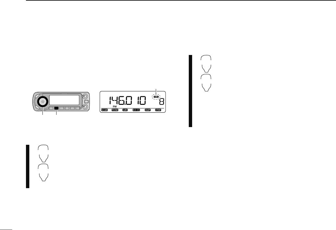
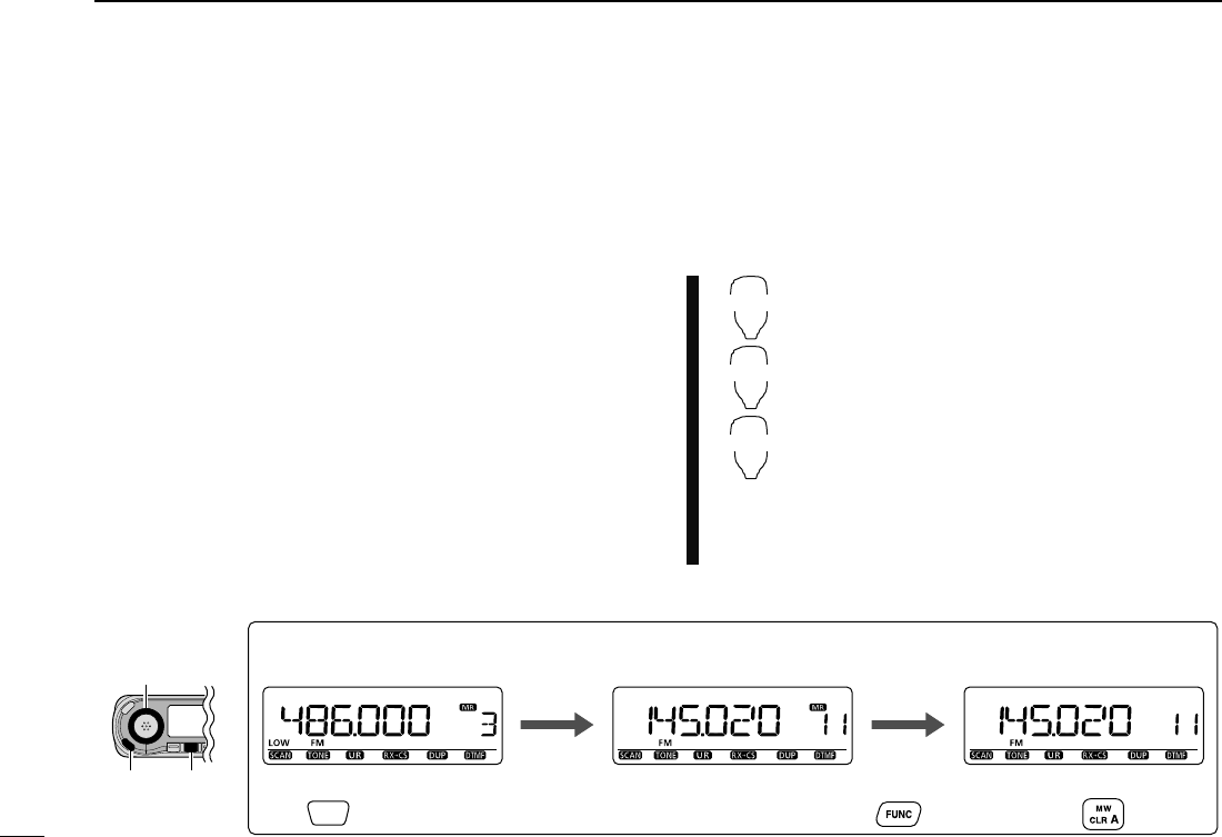
D Using the tuning dial
q Push [M/CALL] several times to select memory mode.
• “X” indicator appears.
w Rotate [DIAL] to select the desired memory channel.
• Programmed memory channels only can be selected.
D Using the [Y]/[Z] keys
z Push [MR/CALL] to select memory mode.
x Push [Y] or [Z] to select and set the desired
memory channel.
• Pushing and holding [Y]/[Z] for 1 sec. activates a
scan.
• If scan is activated, push [Y]/[Z] again or push
[CLR A(MW)] to stop it.
D Using the keypad
z Push [MR/CALL] to select memory mode.
x Push [ENT C(T-OFF)] to activate the keypad
for numeral input.
c Push 3 appropriate digit keys to input a chan-
nel number.
• Blank channel can be selected.
• Push only 1 appropriate digit key, [VOLY 0(TONE-
2)] to
[SIMP 9(16-KEY-L)] then push [M(TONE-1)]
or [SQLZ #(16KEY-L)]
to select scan edge chan-
nels. “M” and “#” can be used for “A” and “B” re-
spectively.
N Selecting a memory channel
7MEMORY/CALL CHANNELS
[DIAL]
Appears
[M/CALL]
MR/CALL
2/3
MR/CALL
ENT
C
c
1
2
3
4
5
6
7
8
9
10
11
12
13
14
15
16
17
18
19
7
MEMORY/CALL CHANNELS
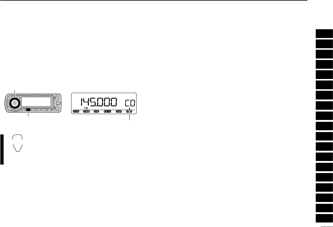
N Selecting a call channel
Call channel is a pre-programmed memory channel that can
be accessed by simply pushing call channel button.
±
Push [M/CALL] several times to select the call channel
mode, then rotate [DIAL] to select the desired call channel.
• “C0” or “C1” appears instead of memory channel number.
±
Push and hold [MR/CALL] for 1 sec. to select
the call channel mode then push [Y]/[Z] to se-
lect the desired call channel in the main band.
• Push [MR/CALL] to select memory mode, or
push [VFO/LOCK] to select VFO mode.
“C0” or “C1” appears
[DIAL]
[M/CALL]
MR/CALL
d
7MEMORY/CALL CHANNELS
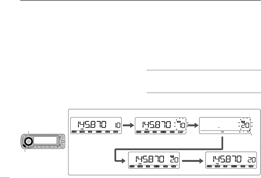
N Memory channel programming
q Push [VFO/MHz] to select VFO mode.
w Set the desired frequency:
± Select the desired band with [BAND].
± Set the desired frequency with [DIAL].
± Set other data (e.g. offset frequency, duplex direction,
tone squelch, current call signs, etc.), if desired.
e Push [S.MW](MW) to enter select memory write mode.
• “X” indicator and the memory channel number blink.
r Rotate [DIAL] to select the desired channel.
• Call channels (C0, C1), VFO and scan edge channels (0A/0B
to 24A/24B), as well as regular memory channels, can be pro-
grammed in this way.
t Push and hold [MW](S.MW) for 1 sec. to program.
• 3 beeps sound.
• Memory channel number automatically increases when continu-
ing to push [MW](S.MW) after programming.
FOR YOUR CONVENIENCE
Memory programming can be performed in various ways e.g.
memory channel to the same (or different) memory channel,
memory channel to the call channel, etc.
Push
and
hold
[MW]
for
1
sec.
to
program
[DIAL]
[S.MW/MW]
Rotate [DIAL] to select channel 20.
VFO mode Enter select memory write mode.
Push [S.MW].
Channel 20
Return to the VFO mode.
[EXAMPLE]: Programming 145.870 MHz into memory channel 20 (blank channel).
e
11
CHAPTER CONTINUED
1
2
3
4
5
6
7
8
9
10
11
12
13
14
15
16
17
18
19
MW
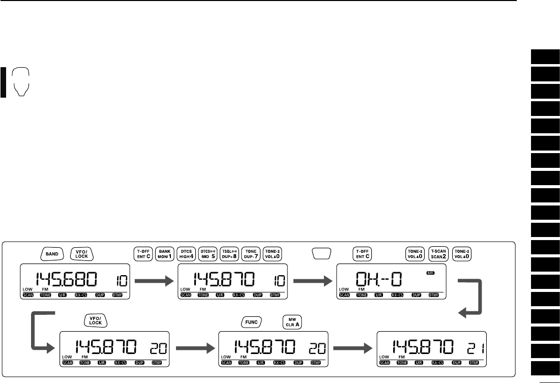
The microphone can also be used to program mem-
ory channels.
z Set the desired frequency in VFO mode.
± Push [VFO/LOCK] to select VFO mode.
± Push [ENT C(T-OFF)], then set the frequency using the
keypad.
± Set other data (e.g. offset frequency, duplex direction,
tone squelch, current call signs, etc.), if desired.
x Push [MR/CALL] to enter memory mode.
c Push [ENT C(T-OFF)], then set the desired memory chan-
nel using the keypad.
v Push [VFO/LOCK] to select VFO mode.
b Push [FUNC] then push and hold [CLR A(MW)] for 1 sec.
to program.
± 3 beeps may sound and the VFO contents (including the
subaudible tone frequency, etc.) are programmed.
± Memory channel number increases when continuing to
push [CLR A(MW)] after programming.
D Programming a memory channel via the microphone
Push ,
Push then for 1 sec. and continue to push
MR/
CALL
Push then Push
Push
[EXAMPLE]: Programming 145.870 MHz into memory channel 20 (blank channel).
f
7MEMORY/CALL CHANNELS
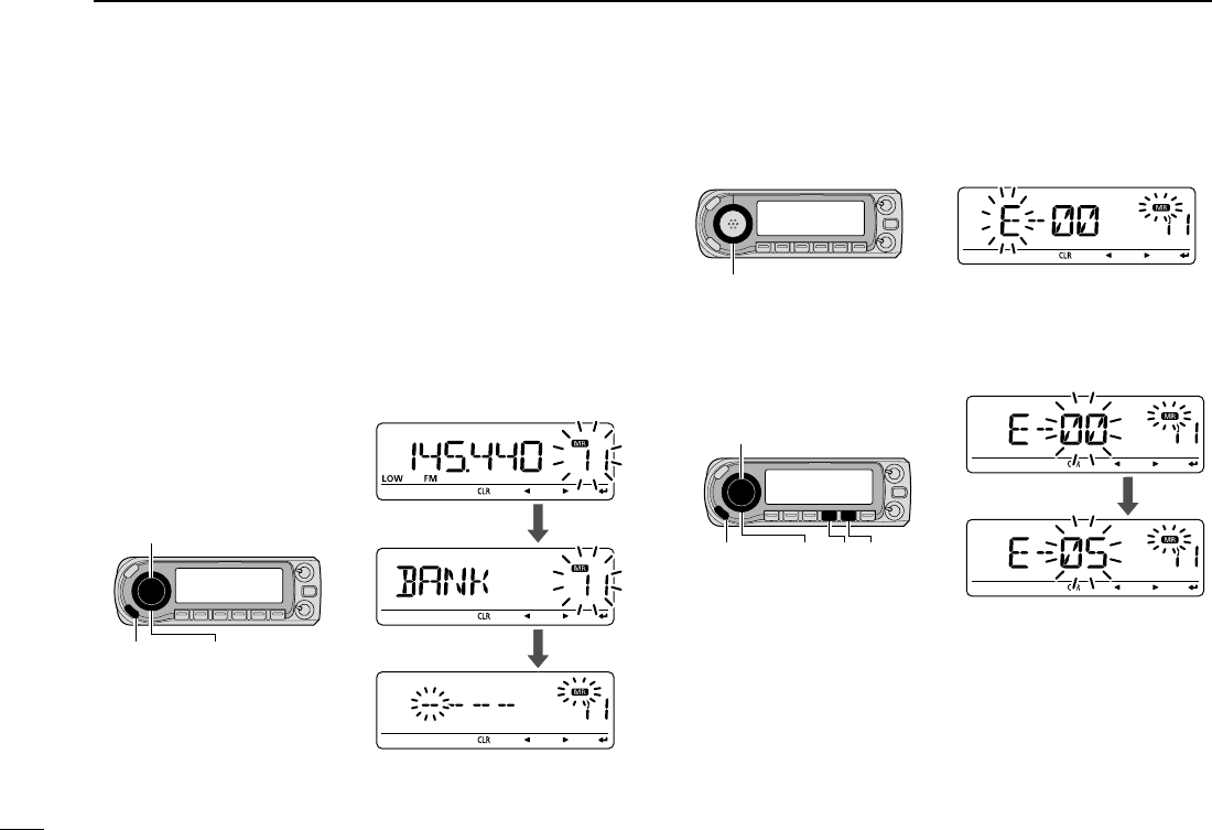
N Memory bank setting
The ID-880H has a total of 26 banks (A to Z). Regular memory
channels, 0 to 999, are assigned to the desired bank for easy
memory management.
q Push [S.MW](MW) to enter select memory write mode.
• “X” indicator and the memory channel number blink.
w Rotate [DIAL] to select the desired memory channel.
e Push
[ ](MONI)
to select “BANK” setting.
r Push
[ ](MONI)
again.
• Bank group and channel number is displayed if the selected mem-
ory channel has already been previously assigned to a bank.
t Rotate [DIAL] to select the bank group.
y
Push [](Low) to select the bank channel digit, then rotate
[DIAL] to select the bank channel number from “00” to “99.”
• Push [
](CS) to return to the bank group selection, if desired.
u After editing, push [BAND] to select “BANK” setting.
i Push [MW](S.MW) for 1 sec. to assign the channel to the
bank.
• Return to the previous indication before entering select memory
write mode.
[BAND]
[DIAL][S.MW/MW]
Push [BAND]
Push [BAND]
[DIAL]
[BAND]
[][]
Rotate [DIAL]
[DIAL][S.MW/MW]
g
11
CHAPTER CONTINUED
1
2
3
4
5
6
7
8
9
10
11
12
13
14
15
16
17
18
19
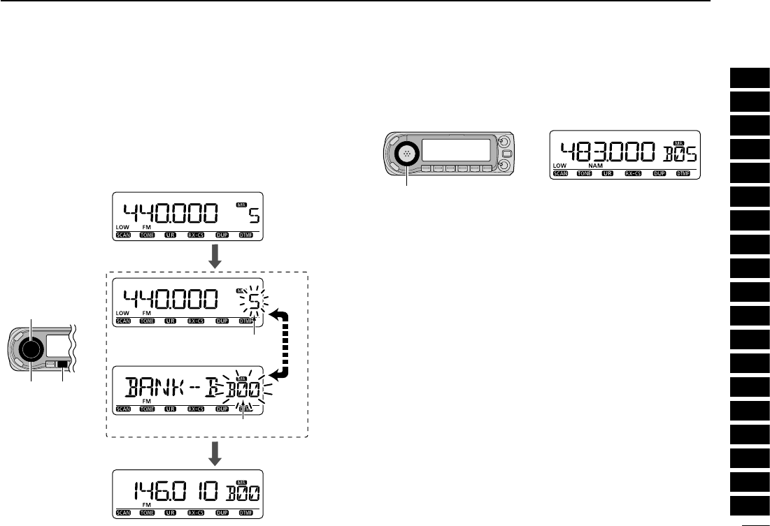
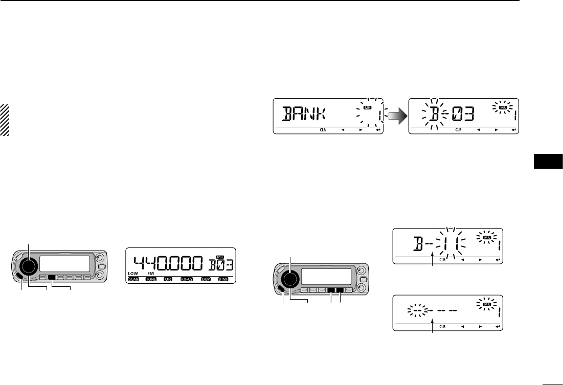
N Memory bank selection
q Push [M/CALL] several times to select memory mode.
w Push [BAND] to enter the bank selection state.
e Rotate [DIAL] to select the desired memory bank group,
then push [BAND] again.
• Only programmed banks are displayed.
• Also regular memory channel can be selected.
r Rotate [DIAL] to select the bank channel.
• Only programmed banks are displayed.
Push [BAND]
Push [BAND]
Regular memory channel
is displayed.
Bank channel is displayed.
[BAND]
[DIAL] [M/CALL]
Rotate [DIAL]
[DIAL]
h
7MEMORY/CALL CHANNELS
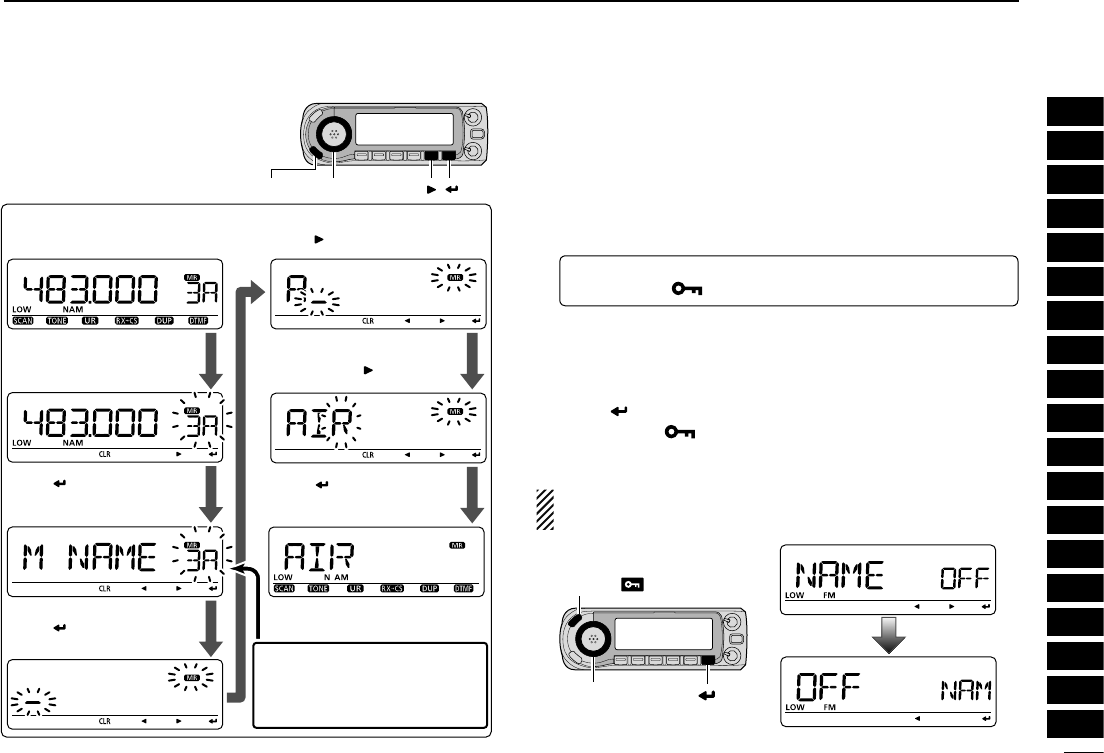
N Programming memory/bank/scan name
Each memory channel can be programmed with an alpha-
numeric channel name for easy recognition and can be in-
dicated independently by channel. Memory and scan names
can be a maximum of 8 characters, and bank name can be a
maximum of 6 characters.
NOTE: Scan name indication can be turned ON or OFF in
DISP set mode (SET). (p. ??)
q Push [M/CALL] to select memory mode.
• To program a call channel name, push [M/CALL] to select call
channel mode.
w Rotate [DIAL] to select the desired memory channel.
• Select scan edge channels (0A/0B to 24A/24B) to program a scan
name.
e Push [S.MW](MW) to enter select memory write mode.
• “X” indicator and the memory channel number blink.
r
Push [ ](MONI).
t Rotate [DIAL] to select “B NAME,” “M NAME” or “S NAME”
when programming the bank name, the memory name or
the scan name, respectively.
y
Push [ ](MONI).
• A cursor blinks for the first character.
u Rotate [DIAL] to select the desired character.
• The selected character blinks.
• Push [
](LOW) to move the cursor right; push [
](CS) to move
the cursor left.
•
Push [CLR](DR) to erase the selected character, or push and hold
[CLR](DR) for 1 sec. to erase all characters followng the cursor.
i Repeat step u until the desired channel name is pro-
grammed.
o
Push [ ](MONI).
t Push and hold [S.MW](MW) for 1 sec. to set the name
and exit channel name programming state.
• 3 beeps sound.
NOTE: Only one bank name can be programmed into
each bank. Therefore, the previously programmed bank
name will be displayed when bank name indication is se-
lected. Also, the programmed bank name is assigned for
the other bank channels automatically.
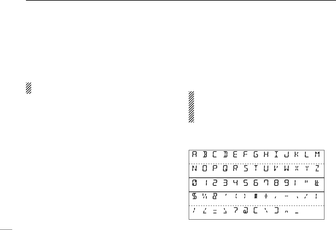
D Available characters
(A) (B) (C) (D) (E) (F) (G) (H) (
I
) (J) (K) (L) (M)
(N) (O) (P) (Q) (R) (S) (T) (U) (V) (W)
(9) (!) (”)(0) (1) (2) (3) (4) (5) (6) (7) (8)
(:)
($) (%) (&) (
’
)
(
;
)(
<
)(
=
) (>) (?)
(
(
)
(X) (Y) (Z)
(#)
(
+
)(
/
)
(
)
)(
)(
,
)(
-
)(
.
)
(
\
)
(
@
)(
)(
]
)(
^
)(
Space
)
i
11
CHAPTER CONTINUED
1
2
3
4
5
6
7
8
9
10
11
12
13
14
15
16
17
18
19
N Selecting memory/bank
name indication
During memory mode operation, either the programmed
memory name or bank name can be displayed.
q
Enter “NAME” in DISP menu.
MENU ¶ SET ¶ DISP ¶ NAME
(p. ??)
(Push [MENU ]), (Rotate [DIAL], then push [BAND].)
w Rotate [DIAL] to select the memory display type.
• OFF : Displays the frequency.
• MEMORY : Displays the memory name.
• BANK : Displays the bank name.
e Push [ ] (MONI) to DISP menu.
r Push [MENU ] to return to the previous indication be-
fore entering DISP menu.
NOTE: The programmed scan name is displayed during
the programmed scan selection.
[DIAL][S.MW/MW]
[EXAMPLE]:
Programming the memory name
“AIR” into the scan edge channel 3A.
[ ][ ]
Push [ ].
During memory mode, rotate
[DIAL] to select 3A.
Push [S.MW] to enter select
memory write mode.
Rotate [DIAL] to enter “A,”
then [ ].
Enter “I” and “R” with
[DIAL] and [ ].
Push [ ], then rotete [DIAL]
to select “M NAME.”
Select “B NAME” or “S NAME”
when program-ming the bank
name or the scan name,
respectively.
Push [ ], then push
[MW]
for 1 sec. to program.
[DIAL]
[MENU ]
[ ]
j
7MEMORY/CALL CHANNELS
N
Copying
memory/call
contents
This function copies a memory channel’s contents to VFO (or
another memory/call channel). This is useful when searching for
signals around a memory channel frequency and for recalling
the offset frequency, subaudible tone frequency etc.
D Memory/call¶VFO
q Select the memory (call) channel to be copied.
± Push [M/CALL] several times to select memory mode
or call channel mode, then rotate [DIAL] to select the
desired channel.
w Push and hold [MW](S.MW) for 2 sec. write the selected
channel contents to VFO mode.
• Returns to VFO mode automatically.
MR/CALL
MW
2/3
z Push [BAND] to select the desired band as
the main band, if necessary.
x Select the memory/call channel to be copied.
± Push [MR/CALL] to select memory mode,
then select the desired memory channel
via [Y]/[Z] or keypad.
± Push and hold [MR/CALL] for 1 sec. then
push [Y]/[Z] to select the call channel.
c Push [FUNC], then push and hold
[CLR A(MW)] for 1 sec. to copy the selected
memory/call channel contents to the VFO.
• VFO mode is selected automatically.
Rotate [DIAL] for selecting memory channel.Push [M/CALL] to select memory mode.
[EXAMPLE]: Copyinig memory channel 11 to VFO.
Push and hold [MW] for 2 sec.
Push then push and hold for 1 sec.
MR/
CALL
Push to select memory mode. Select memory channel.
Front panel operation:
HM-133 operation:
[DIAL]
[M/CALL][MW]
k
11
CHAPTER CONTINUED
1
2
3
4
5
6
7
8
9
10
11
12
13
14
15
16
17
18
19
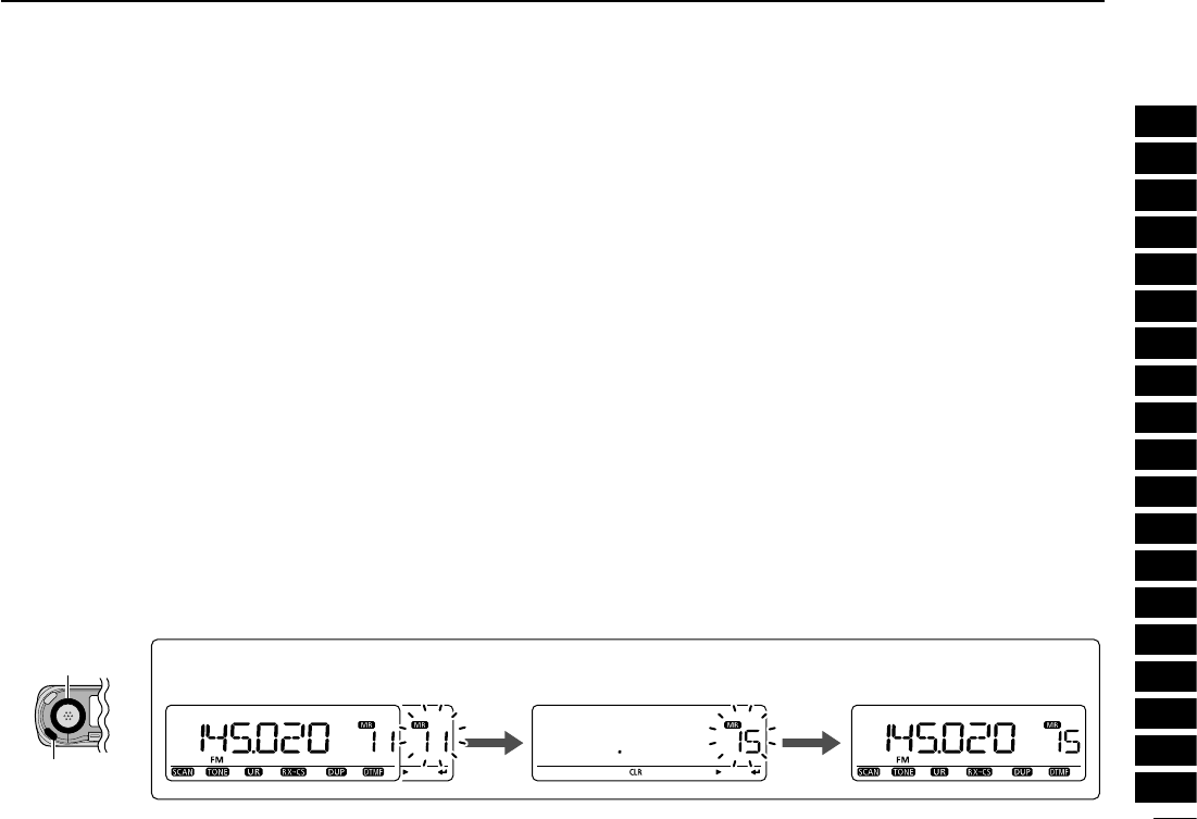
D Memory/call¶call/memory
q Select the memory (call) channel to be copied.
± Push [M/CALL] several times to select memory mode
or call channel mode, then rotate [DIAL] to select the
desired channel.
w Push [S.MW](MW) to enter select memory write mode.
• “X” indicator and the memory channel number blink.
• Do not hold [S.MW](MW) for more than 2 sec., otherwise the
memory contents will be copied to VFO.
e Rotate [DIAL] to select the target memory (call) channel.
• Scan edge channels, 0A/0B to 24A/24B can also be selected.
r Push and hold [MW](S.MW) for 1 sec. to write the selected
channel contents to the target channel.
• The targeted memory and copied contents are indicated.
Rotate [DIAL] to
select a target channel.
Select a memory channel,
then push [S.MW].
[EXAMPLE]: Copyinig memory channel 11 contents to channel 15.
Push and hold [MW] for 2 sec.
[DIAL]
[S.MW/MW]
l
7MEMORY/CALL CHANNELS
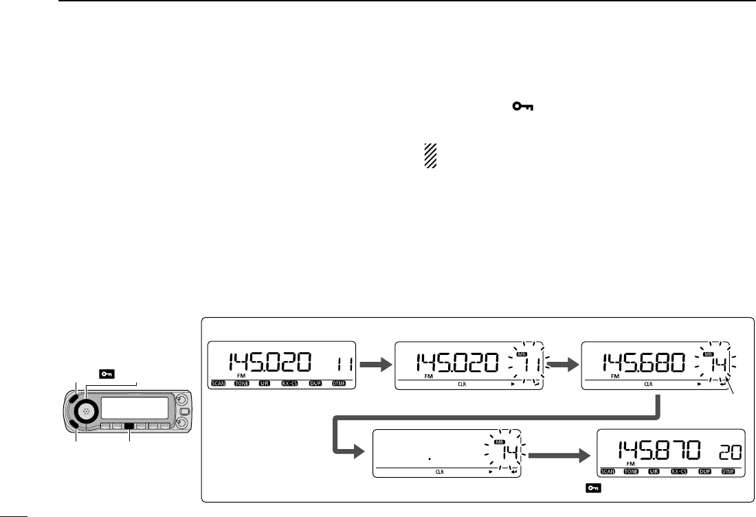
N Memory clearing
Contents of programmed memories can be cleared (erased),
if desired.
q Push [S.MW](MW) to enter select memory write mode.
• “X” indicator and the memory channel number blink.
• Do not hold [S.MW](MW) for more than 2 sec. otherwise
the memory contents will be copied to VFO.
w Rotate [DIAL] to select the desired memory channel to be
cleared.
e Push and hold [CLR](DR) for 1 sec. to clear the contents.
• 3 beeps sound, then the frequency is cleared.
•
“X” indicator and the memory channel number blink continu-
ously.
r Push [MENU ] to the previous indication before enter-
ing select memory write mode.
NOTE: Be careful!— the contents of cleared memories
CANNOT be recalled.
Push
and
hold
[CLR]
for
1
sec.
to
clear.
[DIAL]
[S.MW] [CLR]
Rotate [DIAL] to select channel 14.
Push [S.MW] to enter select memory write mode.
Channel 14
Push [MENU ].
[EXAMPLE]: Clearing memory channel 14.
[MENU ]
m
7
CALL CHANNEL OPERATION
1
2
3
4
5
6
7
8
9
10
11
12
13
14
15
16
17
18
19
The bank contents of programmed memory channels can be
cleared or reassigned to another memory bank.
INFORMATION: Even if the memory bank contents are
cleared, the memory channel contents still remain
programmed.
q Select the desired bank contents to be transferred or
erased from the bank. (p. ??)
± Push [M/CALL] several times to select memory mode.
± Push [BAND], then rotate [DIAL] to select the desired
memory bank group, then push [BAND] again.
± Rotate [DIAL] to select the bank channel.
• Bank initial and bank channel stops blinking.
w Push [S.MW](MW) to enter select memory write mode.
• Displays the original memory channel number automatically, and
then “X” indicator and the memory channel number blink.
• Do not hold [S.MW](MW) for more than 2 sec., otherwise the
memory contents will be copied to VFO.
e Push [BAND] to select “BANK” setting, then push [BAND]
again.
r
Push [](Low) to select the bank channels selection, or
push
[
](CS)
to select the bank group selection to be trans-
ferred.
t
Rotate [DIAL] to select the desired bank group or channel.
• Select “– – – –” indication when erasing the contents from the
bank.
y After editing, push [BAND] to select “BANK” setting.
u Push [MW](S.MW) for 1 sec. to erase/transfer the bank
contents.
N Erasing/transferring bank contents
[BAND]
[DIAL] [M/CALL][S.MW]
[BAND]
[][]
[DIAL][MW]
To transfer the bank contents
to channel 11 in Bank B.
Bank channel is displayed.
To erase.
“– – – –” is dis
p
la
y
ed.
105
10
MENU SCREEN OPERATION
1
2
3
4
5
6
7
8
9
10
11
12
13
14
15
16
17
18
19
N General
MENU screen is used for programming infrequently changed
values or conditions of functions.
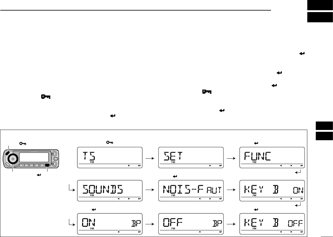
D Entering MENU screen and operation
e.g.) Set “KEY B (Key-touch beep)” to OFF.
q Push [MENU ] to enter MENU screen.
• One of “TS,” “DUP.T,” “SCAN,” “SET,” “DV SET,” “CALL-S,”
“RX CAL,” “MESSAG,” “RPT-L” or “GPS” appears.
w Rotate [DIAL] to select “SET,” then push [ ](MONI).*
• Push [Ω](CS) to select the previous indication.
e Rotate [DIAL] to select “SOUNDS,” then push [ ]
(MONI).*
• Push [Ω](CS) to select the previous indication.
r
Rotate [DIAL] to select “KEY B ,” then push [ ] (MONI).*
• Push [Ω](CS) to select the previous indication.
t Rotate [DIAL] to select “OFF,” then push [ ] (MONI).*
y Push [MENU ] to return to the indication before enter-
ing MENU screen.
*[ ] (MONI) ↔ [BAND MODE]/[≈](LOW)
[DIAL]
[MENU ]
[ ](MONI)
Push [MENU ] Rotate [DIAL] Push [ ](MONI)
Push [ ](MONI)Rotate [DIAL] Rotate [DIAL]
Push [ ](MONI)Push [ ](MONI) Rotate [DIAL]
• Example
106
12 MENU SCREEN OPERATION
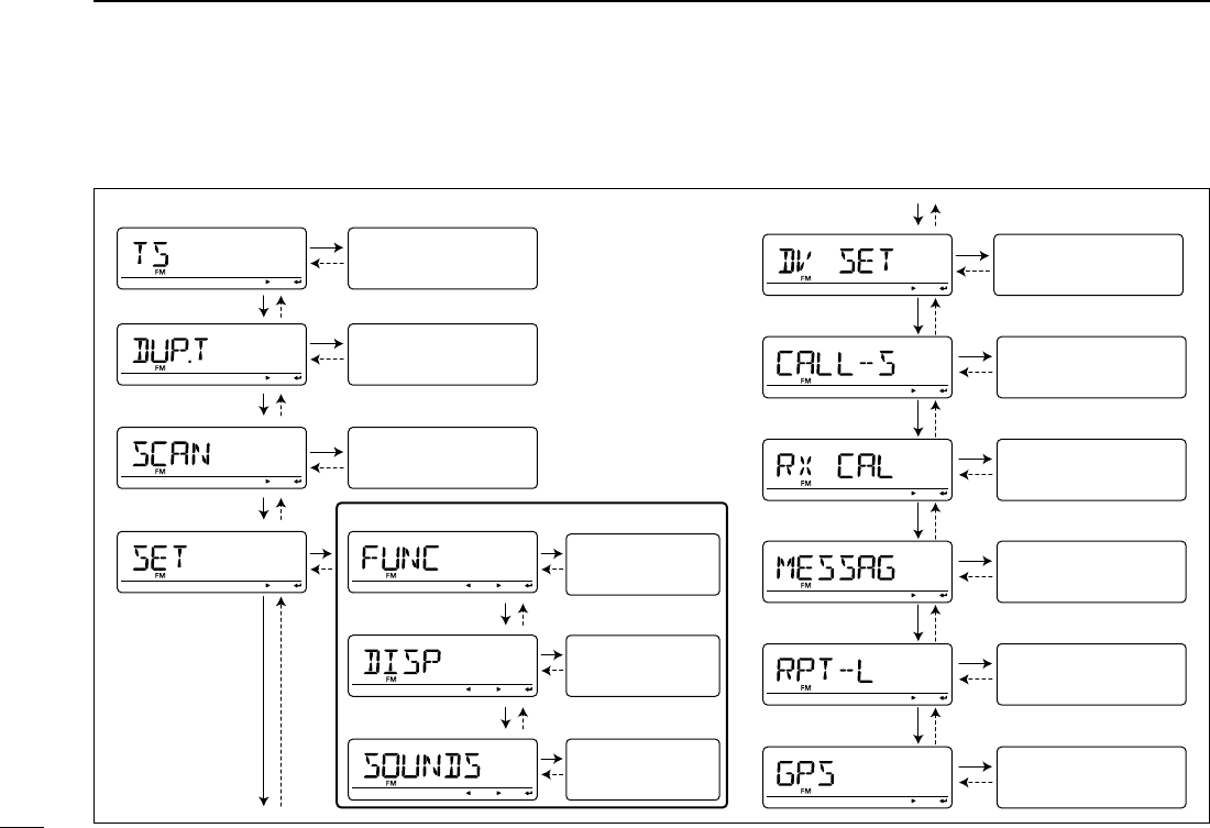
N MENU screen indication and arrangement
MENU screen shows one of the following indication.
• TS mode
• SCAN mode
• SET mode
Setting (see p. 000)
Independent items
(see p. 000)
- FUNC mode
- DISP mode
- SOUNDS mode
• DUP.T mode
Independent items
(see p. 000)
• CALL-S mode
Independent items
(see p. 000)
• RX-CS mode
Independent items
(see p. 000)
• MESSAG mode
Independent items
(see p. 000)
• RPT-L mode
Independent items
(see p. 000)
• GPS mode
Independent items
(see p. 000)
Independent items
(see p. 000)
• DV SET mode
Independent items
(see p. 000)
Independent items
(see p. 000)
Independent items
(see p. 000)
107
12
MENU SCREEN OPERATION
1
2
3
4
5
6
7
8
9
10
11
12
13
14
15
16
17
18
19
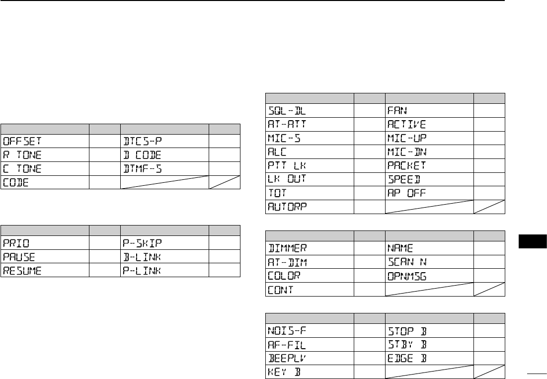
N Items list
D TS mode
See page 000 for details.
D DUP.T mode
Item indication Ref. Item indication Ref.
p. 000 p. 000
p. 000 p. 000
p. 000 p. 000
p. 000
D SCAN mode
Item indication Ref. Item indication Ref.
p. 000 p. 000
p. 000 p. 000
p. 000 p. 000
D SET mode
- FUNC mode
Item indication Ref. Item indication Ref.
p. 000 p. 000
p. 000 p. 000
p. 000 p. 000
p. 000 p. 000
p. 000 p. 000
p. 000 p. 000
p. 000 p. 000
p. 000
- DISP mode
Item indication Ref. Item indication Ref.
p. 000 p. 000
p. 000 p. 000
p. 000 p. 000
p. 000
- SOUNDS mode
Item indication Ref. Item indication Ref.
p. 000 p. 000
p. 000 p. 000
p. 000 p. 000
p. 000
108
12 MENU SCREEN OPERATION
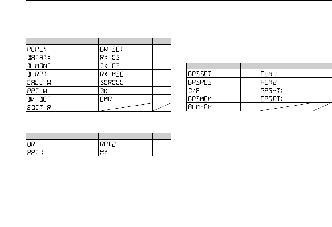
D DV SET mode
Item indication Ref. Item indication Ref.
p. 000 p. 000
p. 000 p. 000
p. 000 p. 000
p. 000 p. 000
p. 000 p. 000
p. 000 p. 000
p. 000 p. 000
p. 000
D CALL-S mode
Item indication Ref. Item indication Ref.
p. 000 p. 000
p. 000 p. 000
D RX CAL mode
See p. 000 for details.
D MESSAG mode
See p. 000 for details.
D RPT-L mode
See p. 000 for details
D GPS mode
Item indication Ref. Item indication Ref.
p. 000 p. 000
p. 000 p. 000
p. 000 p. 000
p. 000 p. 000
p. 000
109
12
MENU SCREEN OPERATION
1
2
3
4
5
6
7
8
9
10
11
12
13
14
15
16
17
18
19
N DUP.T mode items
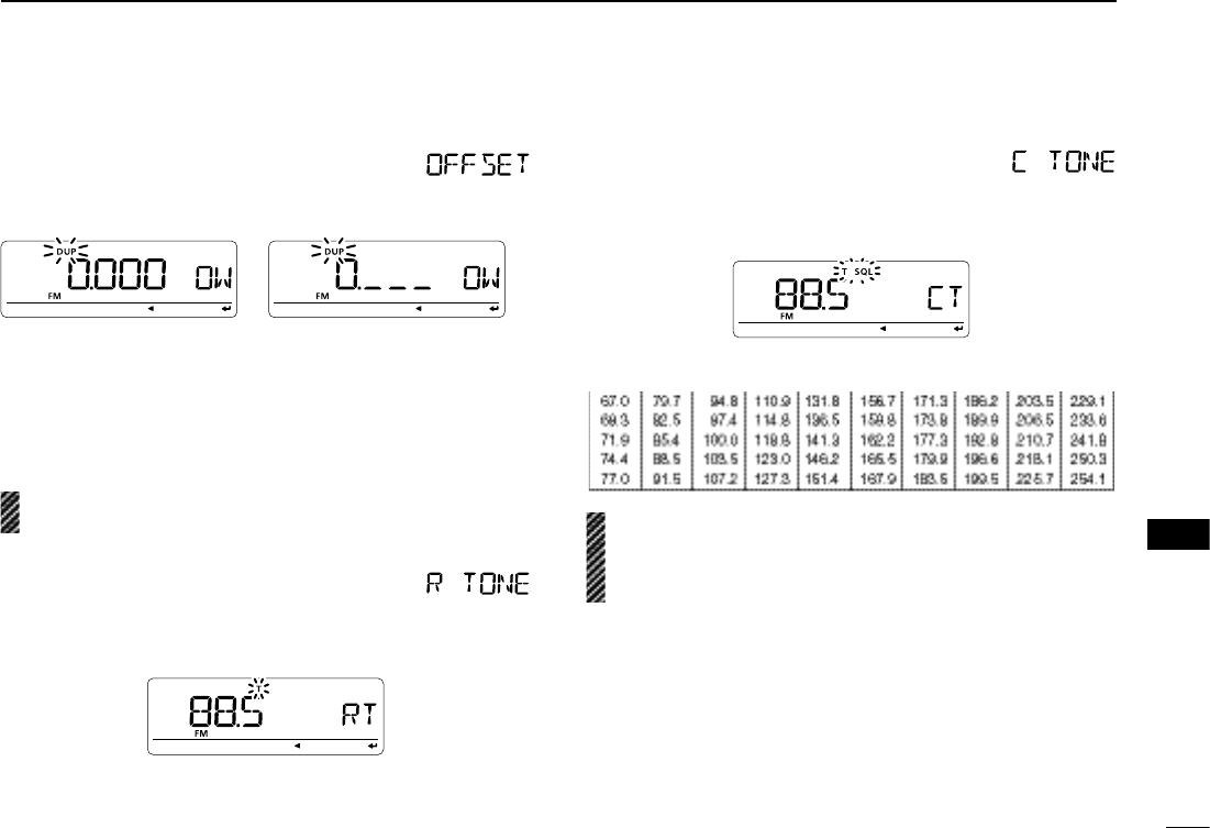
D Offset frequency
Sets the offset frequency for duplex (repeater) operation within
a 0 to 159.995 MHz range.
During 1 MHz step setting
± Push [VFO/MHz] each time to selecting the 10 MHz,
1 MHz step and the setting with the tuning step, selected
in VFO mode, in sequence.
• The default value may differ according to the selected frequency
band (before accessing DUP.T mode) and transceiver version.
The selected tuning step in VFO mode is used when set-
ting the offset frequency.
D Repeater tone frequency
Selects subaudible tone frequency for accessing a repeater,
etc. 50 tone frequencies (67.0–254.1 Hz) are available.
(default: 88.5)
D TSQL frequency
Selects tone frequency for tone squelch or pocket beep oper-
ation from one of 50 available frequencies (67.0–254.1 Hz).
(default: 88.5)
• Available subaudible tone frequencies
The transceiver has 50 tone frequencies and consequently
their spacing is narrow compared with units having 38
tones. Therefore, some tone frequencies may receive in-
terference from adjacent tone frequencies.
110
12 MENU SCREEN OPERATION
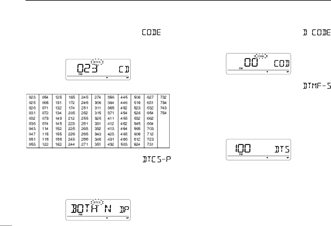
D DTCS code
Selects DTCS (both encoder/decoder) code for DTCS squelch
operation. Total of 104 codes (023–754) are available.
(default: 023)
• Available DTCS codes
D DTCS polarity
Sets DTCS polarity from “BOTH N” (TX/RX: normal), “TN-RR”
(TX: normal, RX: reverse), “TR-RN” (TX: reverse, RX: normal) and
“BOTH R” (TX/RX: reverse). (default: BOTH N)
Transmitting or receiving DTCS code’s polarity is sets by this
item at transmitting side and receiving side respectively.
D Digital code
Sets the desired digital code for digital code squelch opera-
tion. Total of 100 codes (00–99) are available. (default: 00)
D DTMF speed
Select the desired DTMF transmission speed from 100 msec,
200 msec, 300 msec, 500 msec.
• 100 : 100 msec. interval; 5.0 characters per second
(default)
• 200 : 200 msec. interval; 2.5 characters per second
• 300 : 300 msec. interval; 1.6 characters per second
• 500 : 500 msec. interval; 1.0 character per second
111
12
MENU SCREEN OPERATION
1
2
3
4
5
6
7
8
9
10
11
12
13
14
15
16
17
18
19
N Scan mode items
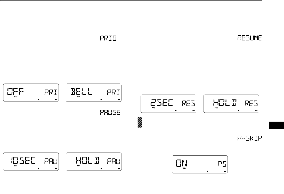
D Priority watch
Activates priority watch or priority watch with alert (Bell).
• OFF : The priority watch is turned OFF. (default)
• ON : The transceiver checks the memory channel
frequency every 5 sec.
• BELL : The transceiver checks the memory channel
frequency every 5 sec. You can be alerted
with beeps and blinking “S.”
D Scan pause timer
Selects the scan pause time. When receiving signals, the
scan pauses according to the scan pause time.
• 2–20SEC : Scan pauses for 2–20 sec. on a received sig-
nal in 2 sec. steps. (default: 10 sec.)
• HOLD : Scan pauses on a received signal until it dis-
appears. Rotate [DIAL] to resume manually.
D Scan resume timer
Selects the scan resume time from a pause after the received
signal disappears.
• 0SEC : Scan resumes when a received signal disap-
pears.
• 1–5SEC : Scan pauses 1–5 sec. after a received signal
disappears. (default: 2 sec.)
• HOLD : Scan remains paused on the received signal
even if it disappears. Rotate [DIAL]† to resume
manually.
Scan resume timer must be set shorter than scan pause
timer (previous item), otherwise this timer does not activate.
D Program skip scan
Sets programmed skip scan setting from ON (default) and
OFF for full scan or programmed scan operation