Itron 100GDLA Utility meter transceiver User Manual 100G Installation Guide draft 102808
Itron, Inc. Utility meter transceiver 100G Installation Guide draft 102808
Itron >
Contents
- 1. Users Manual p1
- 2. Users Manual p2
- 3. Users Manual p3
- 4. Users Manual p4
Users Manual p2
Installing the 100G ERT Module
Natural Gas Solutions 100G Installation Guide for Direct Mounting on Meters 21
xFor Two-Foot Meters: Align the ERT module assembly wriggler with the
meter drive slot (as shown below). It is acceptable for the pin on the 100G
wriggler to be installed inside or outside of the meter drive slot. For ease of
assembly, Itron recommends that the pin on the 100G wriggler be installed
outside of the meter drive slot.
3. Gently place the ERT module assembly on the meter. Align the four screw holes on
the ERT module assembly with the holes on the meter.
4. Turn each screw 1/4 to 1/2 turn after it contacts the cover. Use the 1/4 - 20 x 5/8-inch
screws for this step. You can use the original mounting screws if they were the correct
size and not corroded, otherwise, use the correct size Replacement Screws on page 10.
IMPORTANT Meter manufacturers should torque the mounting screws 15 to 20
inch-pounds.
Chapter 2 American Meter Installation
22 Natural Gas Solutions 100G Installation Guide for Direct Mounting on Meters
5. Place a new tamper seal over two of the mounting screws as shown below.
6. Press the new tamper seals into place using the 11/32-inch nut driver (or another
similar blunt tool).
7. Complete any necessary paperwork. Make sure no excess material is left on the
customer premises; dispose of it properly.
Installing the 100G ERT Module
Natural Gas Solutions 100G Installation Guide for Direct Mounting on Meters 23
The ERT is now installed on the meter.

Chapter 2 American Meter Installation
24 Natural Gas Solutions 100G Installation Guide for Direct Mounting on Meters
Natural Gas Solutions 100G Installation Guide for Direct Mounting on Meters 25
This chapter shows you how to install a 100G ERT Module on a Sensus meter. The
instructions in this chapter apply to 11-tooth, 16-tooth, and 18-tooth Sensus endpoints.
Sensus meters are also known as: Invensys, Equimeter, and Rockwell. For
consistency, these meter types will be referred to as Sensus meters for this
installation procedure.
Installation Prerequisites
The following items are required to install the Itron 100G ERT Module.
Materials Supplied By Itron
The following items are supplied by Itron:
x100G ERT Module
xNew tamper seals
C
H A P T E R
3
Sensus Meter Installation

Chapter 3 Sensus Meter Installation
26 Natural Gas Solutions 100G Installation Guide for Direct Mounting on Meters
Materials Supplied By You
The following tools are required to install, initialize, and check the 100G ERT Module on
the meter.
xSmall and medium flat-blade or Phillips screwdrivers Used to remove and tighten
index and index-cover screws.
xSide-cutting plier/wire snips Used for cutting wire seals, if necessary.
xSmall putty knife Used to remove all traces of old gaskets from the meter.
xMeter seals, wire seals, and seal press Used to secure the meter from tampering, if
necessary.
x11/32-inch nut driver or other blunt tool Used to securely seat new tamper plugs
over screw holes.
xReplacement screws Used to mount 100G ERT Module assembly to meter and
index to module assembly backplates.
xFC200SR with EndPoint-Link or EndPoint-Link Pro software Used to program
and check ERT assembly.
Replacement Screws
Replacement screws used in this procedure include:
For mounting the 100G ERT Module assembly on the meter:
xUse 10 - 24 x5/8-inch slotted, Fillister head screws.
For mounting the index on the 100G ERT Module backplate:
xUse 6 - 32 x 5/8-inch slotted, round head screws.
Pre-installation Preparations
Before installing the 100G ERT Module on a meter, verify:
xAll Itron 100G ERT Module gas modules are compatible with your brand of
gas meter. See the Meter Compatibility List for compatible meter model
numbers for the 100G ERT Module
Installing the 100G ERT Module
Natural Gas Solutions 100G Installation Guide for Direct Mounting on Meters 27
Installing the 100G ERT Module
There are four steps to installing the 100G ERT Module on a meter:
xRemove the index
xAssemble the 100G ERT Module
xProgram the 100G ERT Module
xAttach the 100G ERT Module to the meter.
NOTE Properly dispose of all unused screws, old index covers, gaskets, tamper
seals, and other left over materials. Do not leave any materials on customer
premises.
Remove the Index
The first step to install a 100G ERT Module on the meter is to remove the index from the
meter.
To Remove the Index
1. Remove any tamper seals from the meter.
2. Detach the index cover from the meter by removing the four screws holding it in
place.
3. Examine the index cover screws you removed. Verify they are 5/8-inch long and are
not corroded.
xIf the screws are 5/8-inch long and are not corroded, keep them for later use.
xIf they are an incorrect length or are corroded, dispose of them properly. Use 10
- 24 x 5/8-inch screws as described in Replacement Screws on page 26.
Chapter 3 Sensus Meter Installation
28 Natural Gas Solutions 100G Installation Guide for Direct Mounting on Meters
TIP Use the index cover you just removed as a temporary storage location
for screws.
NOTE Dispose of the index cover properly when finished with the installation
procedure. Do not leave it on customer premises.
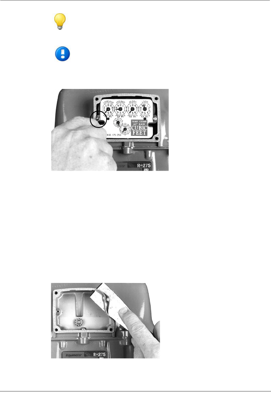
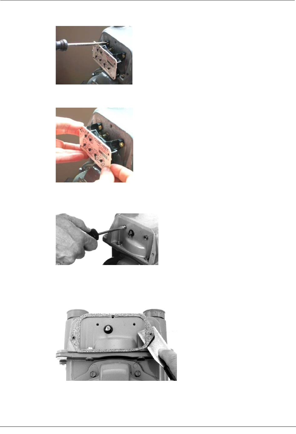
4. Unscrew one index mounting screw completely.
5. Remove the other index mounting screw.
6. Place the index where it will not be damaged; get filled with dirt, rain or snow; or fall
to the ground or floor. The index will be used later in this procedure.
7. Examine the index screws you just removed. Verify that they are 5/8-inch long and
are not corroded.
xIf the screws are 5/8-inch long and are not corroded, keep them for later use.
xIf the screws are an incorrect length or are corroded, dispose of them properly.
Use 6 -32 x 5/8-inch screws as described in Replacement Screws on page 26, if
required.
8. Use a putty knife or similar object to completely remove the old index gasket from the
meter (if applicable). All traces of the gasket must be removed before the ERT is
installed.
Installing the 100G ERT Module
Natural Gas Solutions 100G Installation Guide for Direct Mounting on Meters 29
Assemble the ERT Module
The next step in the 100G ERT Module installation is to create the endpoint module
assembly by attaching the endpoint backplate and cover to the meter index.
To Assemble the ERT
1. Obtain a new 100G ERT Module.
2. Separate the ERT module backplate from the cover.
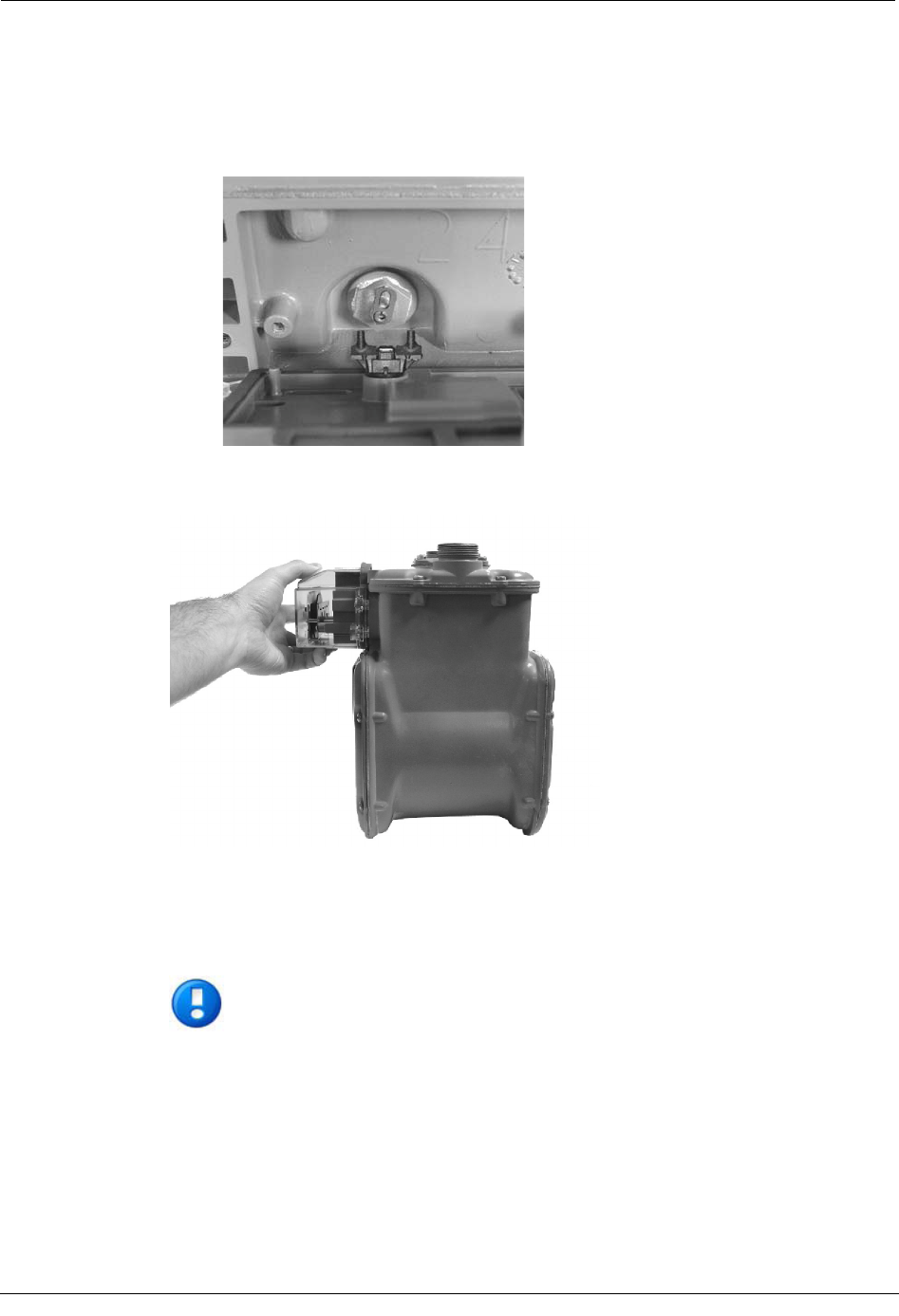
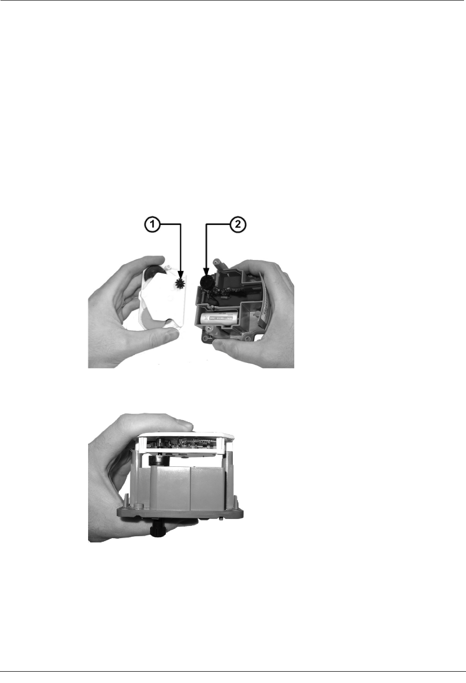
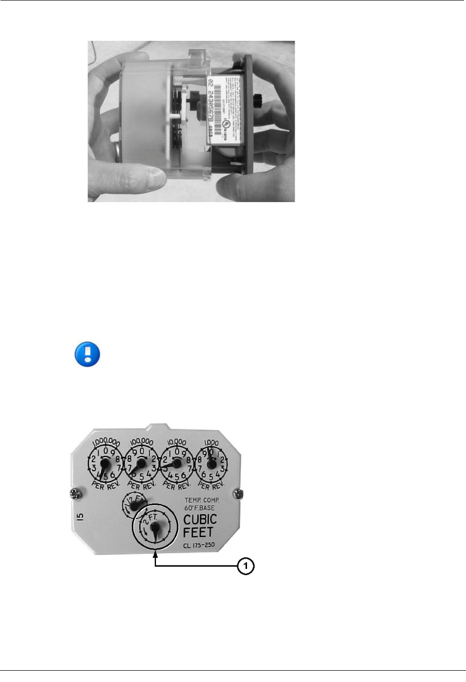
3. Place the index drive gear (1) in the backplate wriggler gear cup (2) of the ERT. The
following picture shows an 11-tooth drive gear. If your index has a 16- or 18-tooth
drive gear, you must use the appropriate 100G ERT Module for your meter. See the
Meter Compatibility list on page 2 for more information.
Once properly in place, the index drive gear and backplate wriggler cup should look
similar to the following example.
Chapter 3 Sensus Meter Installation
30 Natural Gas Solutions 100G Installation Guide for Direct Mounting on Meters
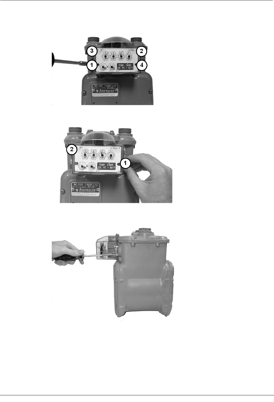
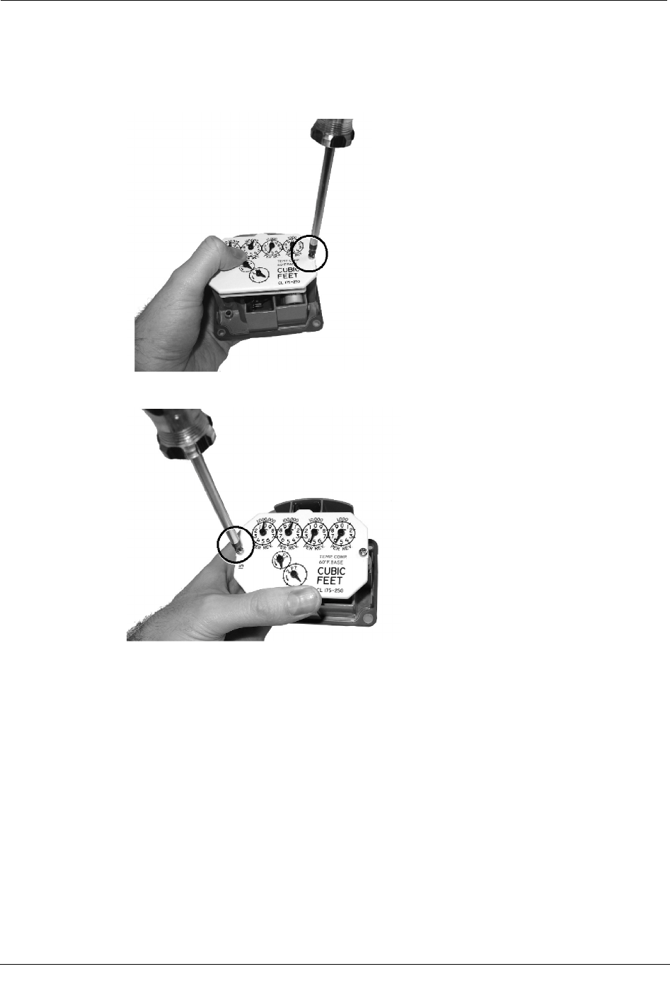
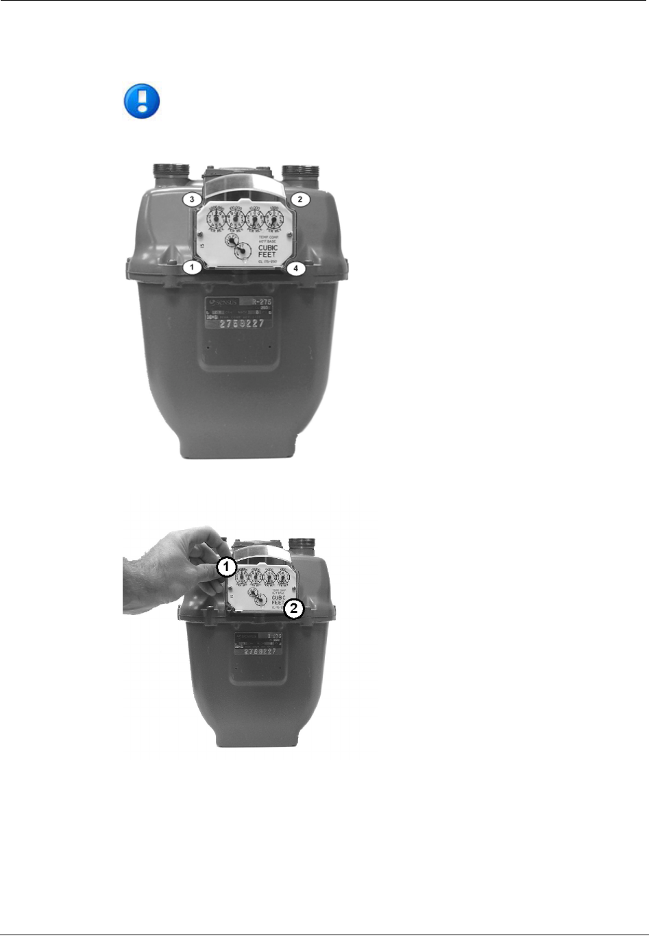
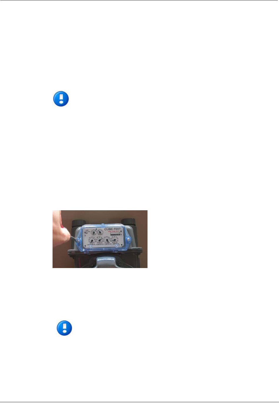
4. Attach the right-hand mounting screw to the index and meter, just far enough to hold
the index in place. Use one 6 - 32 x 5/8-inch screw for this step (you can use an
original mounting screw if it was the correct size and not corroded; otherwise, use the
correct size Replacement Screw on page 26).
5. Install and tighten the left-hand index mounting screw.
6. Tighten the right-hand index mounting screw completely.
Installing the 100G ERT Module
Natural Gas Solutions 100G Installation Guide for Direct Mounting on Meters 31
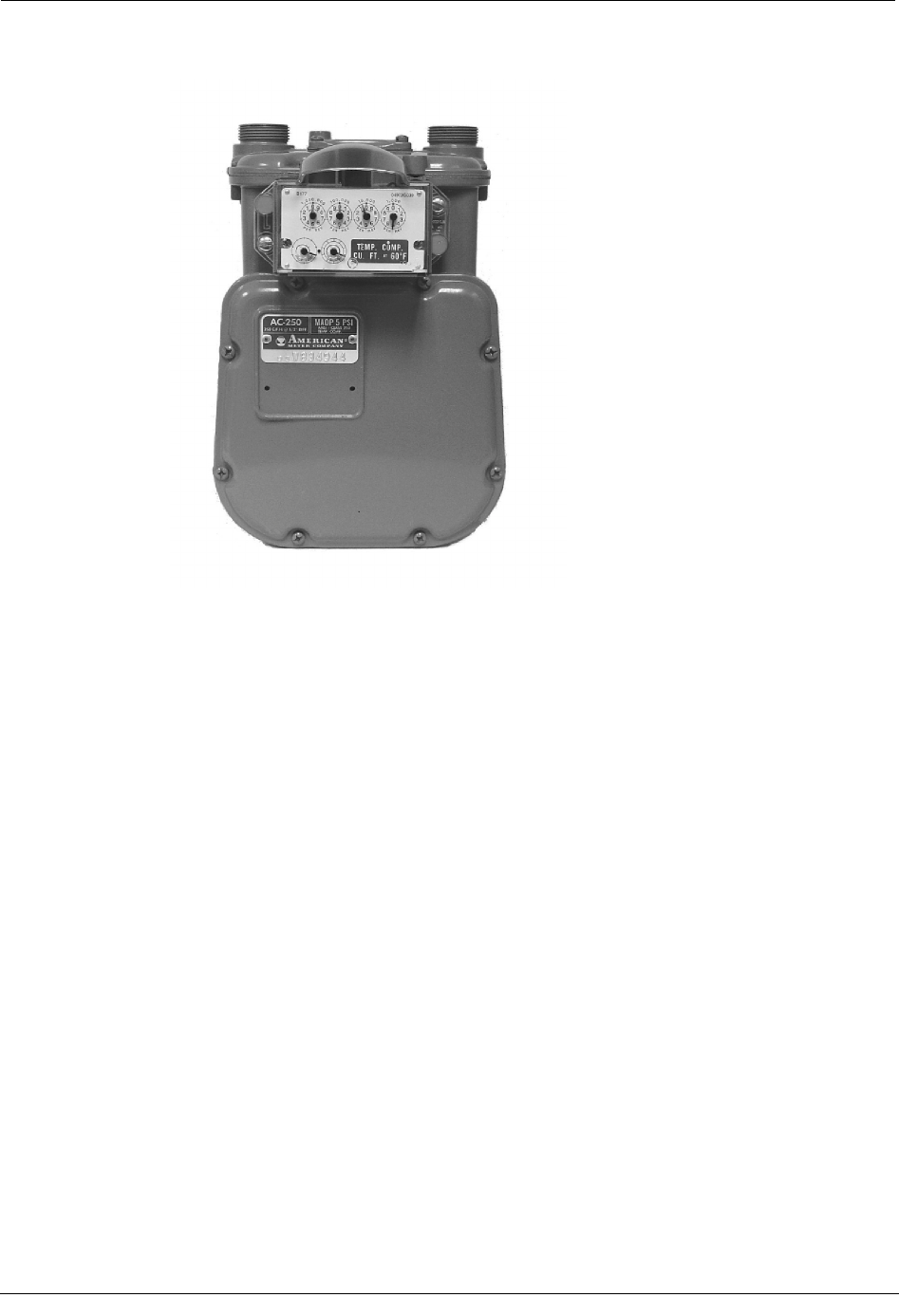
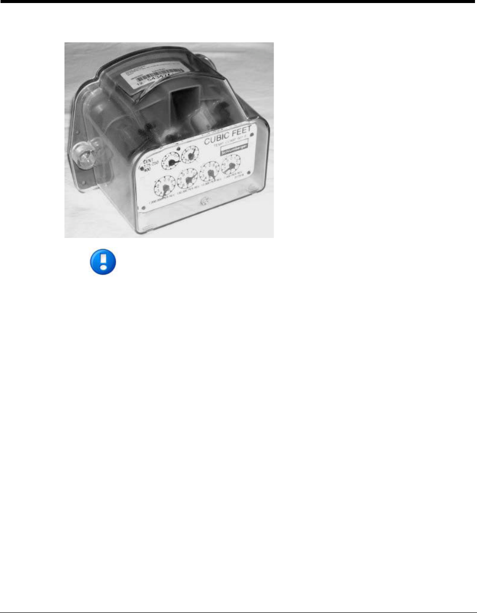
7. Slide the ERT cover over the index and backplate.
8. Verify that the cover is installed correctly.
Next, program the ERT module.
Program the ERT
The ERT must be programmed using the FC200SR with EndPoint-Link software. See the
Endpoint-Link ERT Programming Guide (TDC-0411) for more information.
IMPORTANT You must perform the following programming procedure for
the ERT module to function properly.
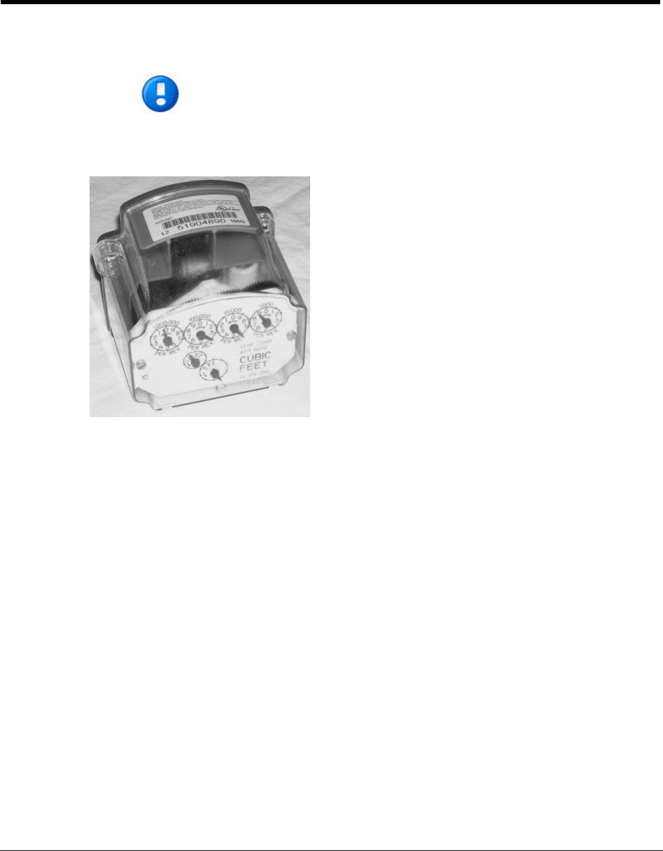
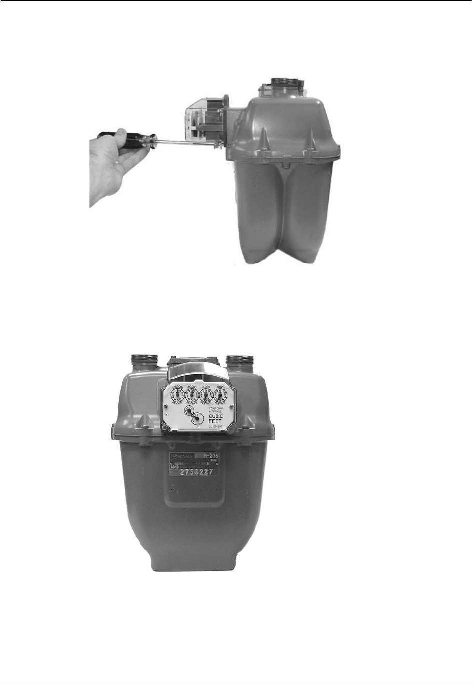
Sensus meters. Sensus meters have a 2-foot drive rate, as indicated in the example below
(1), or a 0.05 cubic meter drive (not shown).
Chapter 3 Sensus Meter Installation
32 Natural Gas Solutions 100G Installation Guide for Direct Mounting on Meters
To Program the ERT Module
1. Using the FC200SR, program the reading of the index that was on the meter into the
ERT module assembly.
xFor initial programming, hold the FC200SR approximately 1 foot away from
the 100G.
xFor reprogramming (30 days or more past initial programming), hold the
FC200SR approximately 4 to 5 feet away from the 100G.
Be sure to program the 100G to the correct mode for the reading technology that will
be used (for example, Fixed Network Mode, Mobile/Handheld Mode, or Hard to Read
Mobile/Handheld Mode). In Endpoint-Link Pro v5.0, you will have access to the one
mode that was defined by your system administrator.
During programming, the 100G ERT module is programmed to the nearest 100 cubic
feet; the last two digits (the tens and units) are programmed as zeros (0). Once
programming is complete, however, the ERT module assembly can be read to the
nearest cubic foot.
2. Slowly turn the ERT module drive wriggler two turns in the direction indicated on the
index drive rate. This lets you verify the ERT module is counting properly after
assembly.
IMPORTANT Do not turn the drive wriggler faster than one turn per second.
3. Read the ERT module assembly using the FC200SR. Consult the EndPoint-Link ERT
Programming Guide (TDC-0411) or other applicable instructions for details on how to
read an ERT.
xIf this reading is higher than the one you programmed in step 1 above, the ERT
module assembly is counting correctly.
xIf the ERT module assembly reading is not higher than what was programmed
in step 1, replace the ERT module with a new one.
Installing
the 100G ERT Module
Natural Gas Solutions 100G Installation Guide for Direct Mounting on Meters 33
Attach the ERT to the Meter
After the endpoint has been programmed and is reading correctly, it must be attached to the
meter. Follow the steps below to do this.
To Attach the ERT to the Meter
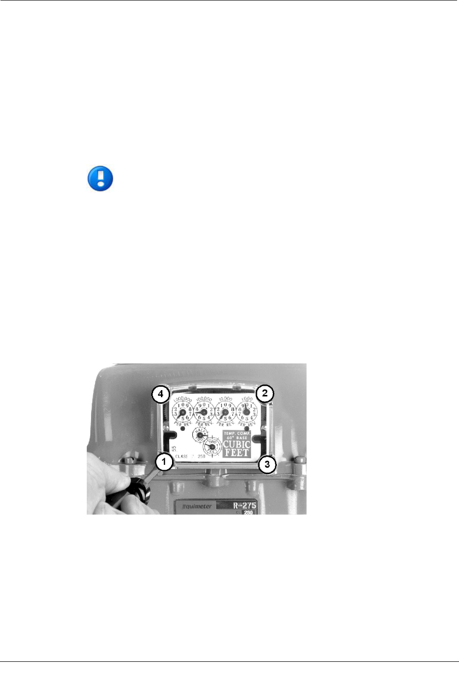
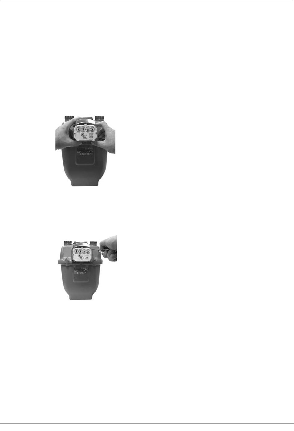
1. Gently place the ERT module assembly against the front of the meter as shown. Make
sure all four mounting screw holes in the ERT module assembly line up with the
corresponding holes on the meter. The 100G ERT Module has molded tabs on the
outer edge of its housing to make direct mounting easier.
2. Insert the top-right cover mounting screw. Tighten the screw just enough to hold the
ERT module assembly in place. Use the 10 - 24 x 5/8-inch screws for this and the
following step (you can use the original mounting screws if they were the correct size
and not corroded; otherwise, use the correct size as described in Replacement Screws
on page 26).
Chapter 3 Sensus Meter Installation
34 Natural Gas Solutions 100G Installation Guide for Direct Mounting on Meters
3. Turn each screw 1/4 to 1/2 turn after it contacts the cover.
IMPORTANT Meter manufacturers should torque the mounting screws 15 to 20
inch-pounds.
4. Place a new tamper seal over two of the mounting screws as shown below.
Installing the 100G ERT Module
Natural Gas Solutions 100G Installation Guide for Direct Mounting on Meters 35
5. Press the new tamper seals into place using the 11/32-inch nut driver (or another
similar blunt tool).
6. Complete any necessary paperwork. Make sure no excess material is left on the
customer premises.
The ERT is now installed on the meter.

Chapter 3 Sensus Meter Installation
36 Natural Gas Solutions 100G Installation Guide for Direct Mounting on Meters
Natural Gas Solutions 100G Installation Guide for Direct Mounting on Meters 37
This chapter shows you how to install a 100G ERT Module on an Actaris meter.
Actaris meters are also known by the names: Sprague, and
Schlumberger. For consistency, all of these meter types will be referred
to as Actaris meters for this installation procedure.
Installation Prerequisites
The following items are required to install the Itron 100G ERT Module.
Materials Supplied By Itron
The following items are supplied by Itron:
x100G ERT Module
xNew tamper seals
C
H A P T E R
4
Actaris Meter Installation

Chapter 4 Actaris Meter Installation
38 Natural Gas Solutions 100G Installation Guide for Direct Mounting on Meters
Materials Supplied By You
The following tools are required to install, initialize, and check the 100G ERT Module on
the meter.
xSmall and medium flat-blade or Phillips screwdrivers Used to remove and tighten
index and index-cover screws.
xSide-cutting plier/wire snips Used for cutting wire seals, if necessary.
xSmall putty knife Used to remove all traces of old gaskets from the meter.
xMeter seals, wire seals, and seal press Used to secure the meter from tampering, if
necessary.
x11/32-inch nut driver or other blunt tool Used to securely seat new tamper plugs
over screw holes.
xReplacement screws Used to mount 100G ERT Module assembly to meter and
index to module assembly backplates.
xFC200SR with EndPoint-Link or EndPoint-Link Pro software Used to program
and check ERT assembly.
Replacement Screws
Replacement screws used in this procedure include:
For mounting 100G ERT Module assemblies on meters:
xUse 10 - 24 x 5/8-inch slotted, Fillister head screws.
For mounting indexes on 100G ERT Module backplates:
xUse 10 - 24 x 1/4-inch slotted, round head screws.
Pre-installation Preparations
Before installing the 100G ERT Module on a meter, verify:
xAll Itron 100G ERT Module gas modules are compatible with your brand of gas
meter.
xSee the Meter Compatibility List for compatible meter model numbers for the
100G ERT Module
Installing the 100G ERT Module
Natural Gas Solutions 100G Installation Guide for Direct Mounting on Meters 39
Installing the 100G ERT Module
There are four steps to installing the 100G ERT Module on a meter:
xRemove the index
xAssemble the 100G ERT Module
xProgram the 100G ERT Module
xAttach the 100G ERT Module to the meter.
NOTE Properly dispose of all unused screws, old index covers, gaskets, tamper
seals, and other left over materials. Do not leave any materials on customer
premises.
Remove the Index
The first step to install a 100G ERT Module on the meter is to remove the index from the
meter.
To remove the index
1. Remove tamper seals from the meter.
2. Remove the index cover from the meter by removing the four screws holding it in
place.
3. Examine the index cover screws you removed. If they are 5/8 inches long and not
corroded, you can use them to attach the 100G ERT Module to the meter.
If the screws are not the correct length, or are corroded, dispose of them properly.
Replace them with the screws listed in Replacement Screws on page 38.
4. Use the removed index cover as a temporary storage location for screws.
NOTE Dispose of the index cover properly when finished with the installation
procedure. Do not leave it on customer premises.
Chapter 4 Actaris Meter Installation
40 Natural Gas Solutions 100G Installation Guide for Direct Mounting on Meters
5. Loosen the index mounting screws one-half turn.
6. Slide the index off its mounting screws and remove from the meter. Set the index
where it won't get damaged or dirty.
7. Remove the index mounting screws from the meter. Check the screws for length and
corrosion. If they are 1/4 inches long and not corroded, you can use them to attach the
index to the 100G ERT Module.
If the screws are not the correct length, or are corroded, dispose of them properly.
Replace them with the screws listed in Replacement Screws on page 38.
8. Remove all traces of the old index gasket from the meter. The new 100G ERT Module
has its own gasket.
9. Dispose of the old gasket properly. Do not leave it on the customer premises.
Installing the 100G ERT Module
Natural Gas Solutions 100G Installation Guide for Direct Mounting on Meters 41
Assemble the ERT Module
The next step in the 100G ERT Module installation is to create the endpoint module
assembly by attaching the endpoint backplate and cover to the meter index.
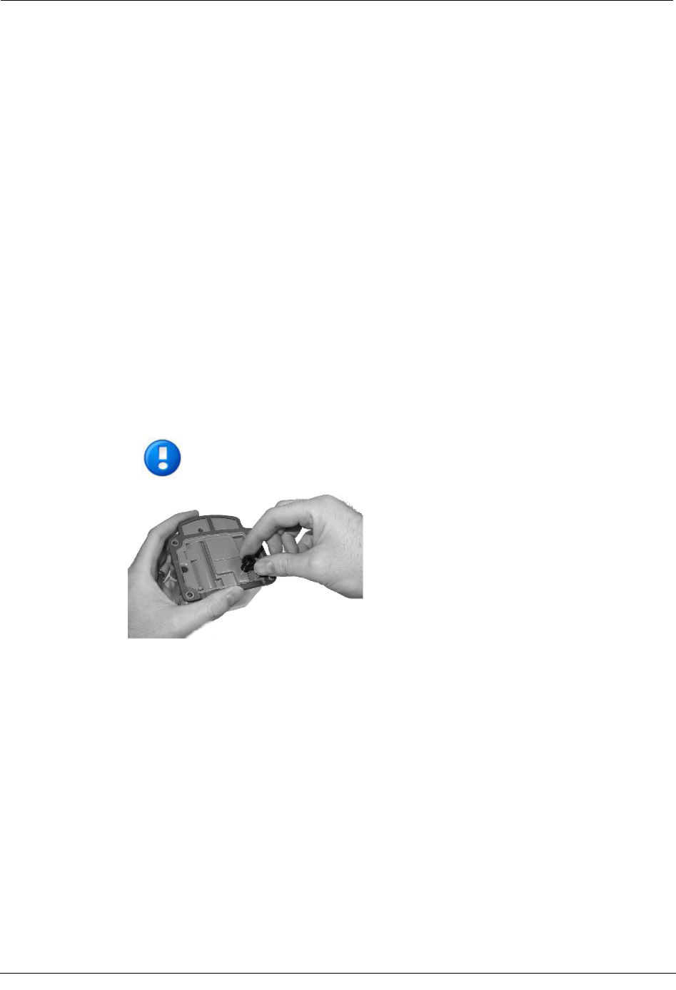
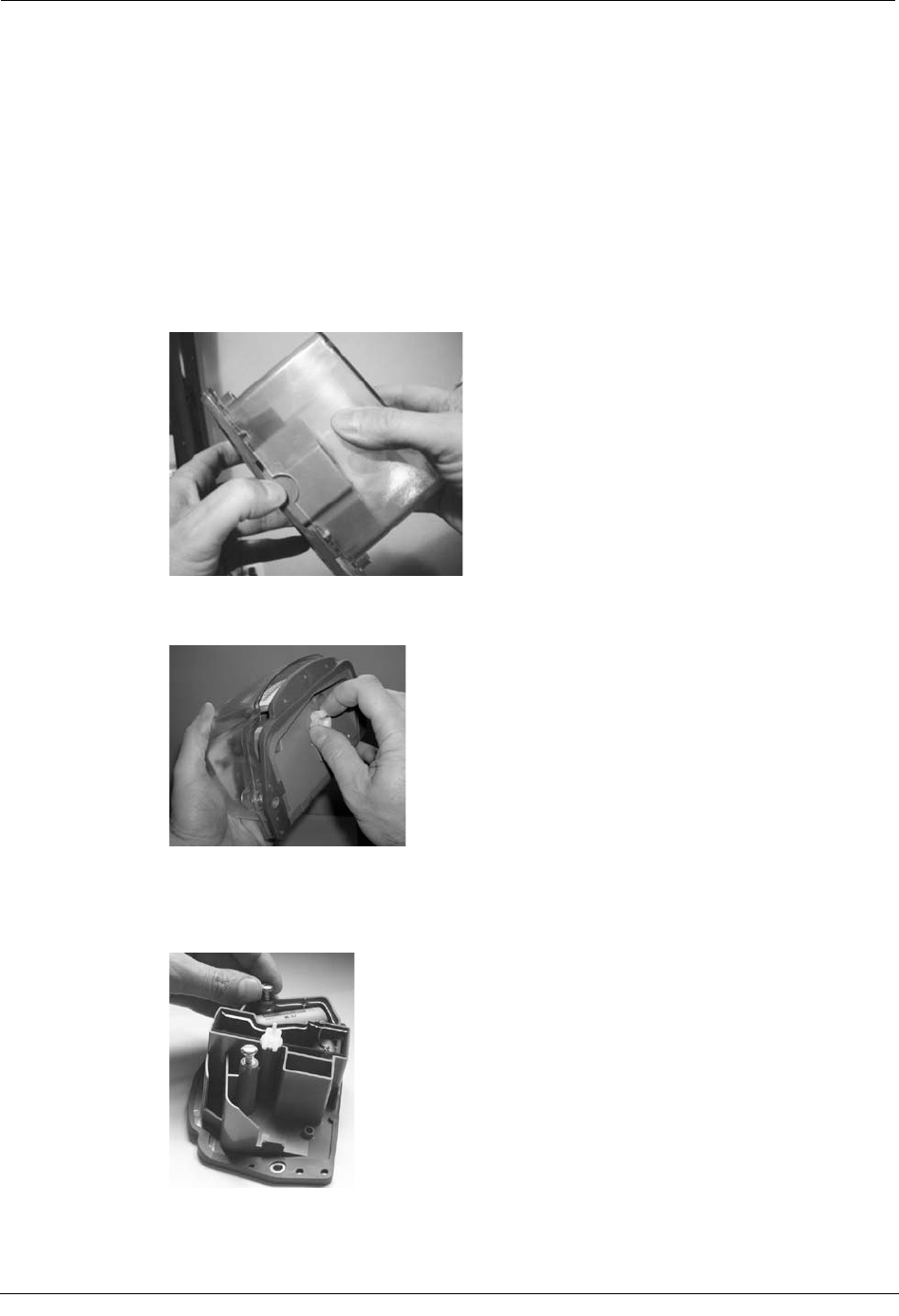
To Separate the Cover from the Backplate
1. Obtain a new 100G ERT Module.
2. Place your thumb in the notch on the bottom of the endpoint to hold the backplate and
pull the cover away from the backplate.
You can also separate the cover from the backplate by gently pulling on the wriggler
until the backplate comes free.
3. Set the cover aside where it won't be damaged.
4. Put the index mounting screws about two turns into the backplate index mounting
posts.
Chapter 4 Actaris Meter Installation
42 Natural Gas Solutions 100G Installation Guide for Direct Mounting on Meters
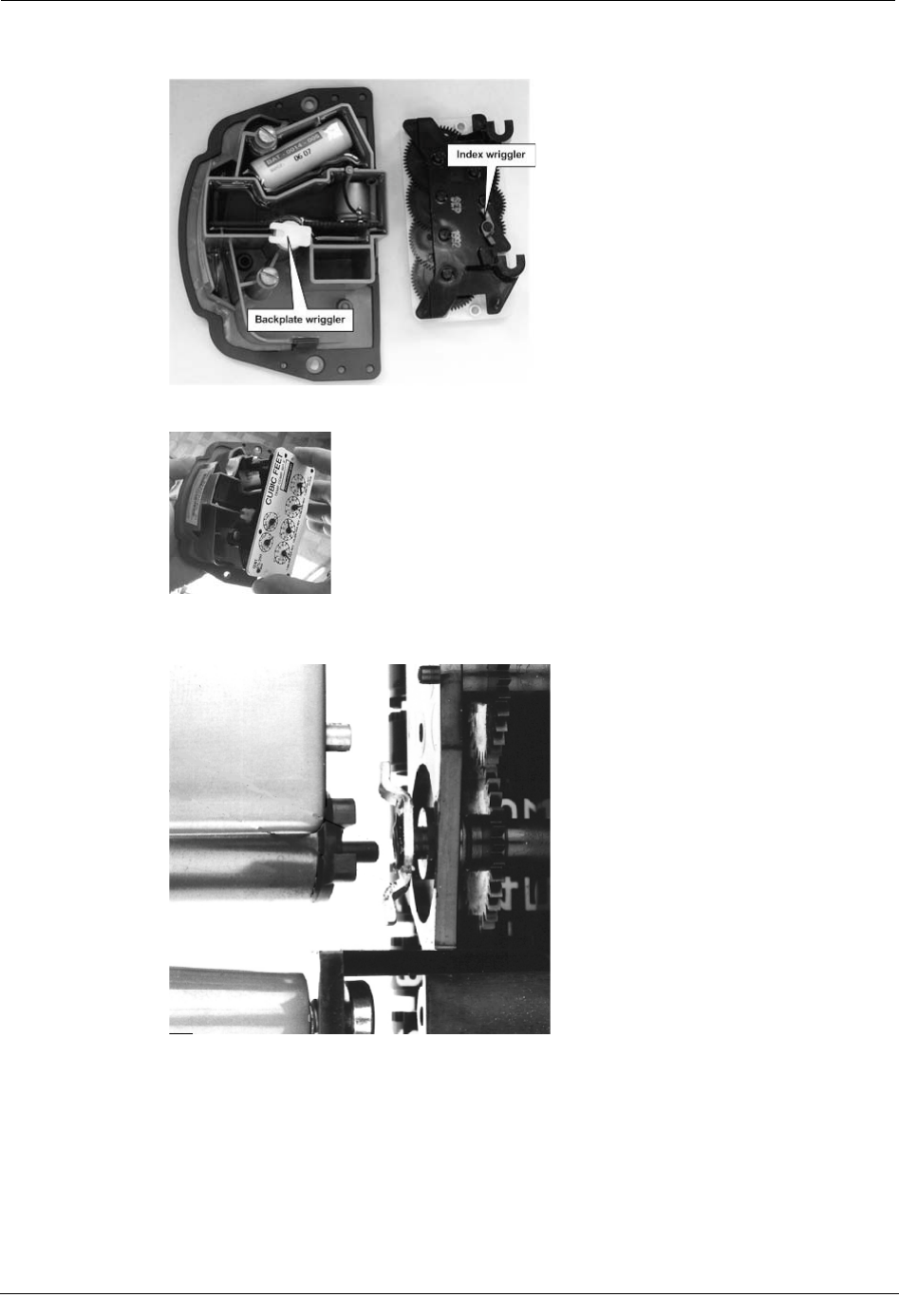
5. Position the backplate and index wrigglers as shown below.
6. Slide the index mounting brackets onto the mounting screws.
7. Make sure the backplate wriggler post is below the index wriggler when lowering the
index mounting brackets onto the index mounting screws.
Installing the 100G ERT Module
Natural Gas Solutions 100G Installation Guide for Direct Mounting on Meters 43
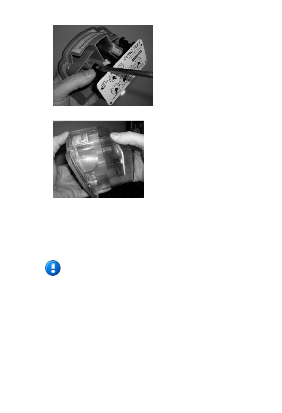
8. Hold the index in place with your thumb and tighten the index mounting screws.
9. Slide the cover over the index and onto the backplate until it is against the gasket.
Program the ERT
The ERT must be programmed using the FC200SR with EndPoint-Link software. See the
Endpoint-Link ERT Programming Guide (TDC-0411) for more information.
IMPORTANT You must perform the following programming procedure for
the ERT module to function properly.

Chapter 4 Actaris Meter Installation
44 Natural Gas Solutions 100G Installation Guide for Direct Mounting on Meters
To program the ERT module
1. Using the FC200SR, program the reading of the index that was on the meter into the
ERT module assembly.
xFor initial programming, hold the FC200SR approximately 1 foot away from
the 100G.
xFor reprogramming (30 days or more past initial programming), hold the
FC200SR approximately 4 to 5 feet away from the 100G.
Be sure to program the 100G to the correct mode for the reading technology that will
be used (for example, Fixed Network Mode, Mobile/Handheld Mode, or Hard to Read
Mobile/Handheld Mode). In Endpoint-Link Pro v5.0, you will have access to the one
mode that was defined by your system administrator.
During programming, the 100G ERT module is programmed to the nearest 100 cubic
feet; the last two digits (the tens and units) are programmed as zeros (0). Once
programming is complete, however, the ERT module assembly can be read to the
nearest cubic foot.
2. Slowly turn the ERT module drive wriggler two turns in the direction indicated on the
index drive rate. This lets you verify the ERT module is counting properly after
assembly.
IMPORTANT Do not turn the drive wriggler faster than one turn per second.
3. Read the ERT module assembly using the FC200SR. Consult the EndPoint-Link ERT
Programming Guide (TDC-0411) or other applicable instructions for details on how to
read an ERT.
xIf this reading is higher than the one you programmed in step 1 above, the ERT
module assembly is counting correctly.
xIf the ERT module assembly reading is not higher than what was programmed
in step 1, replace the ERT module with a new one.
Installing the 100G ERT Module
Natural Gas Solutions 100G Installation Guide for Direct Mounting on Meters 45
Attach the 100G ERT Module to the Meter
After the endpoint has been programmed and is reading correctly, it must be attached to the
meter. Follow the steps below to do this.
To attach the 100G ERT Module to the meter
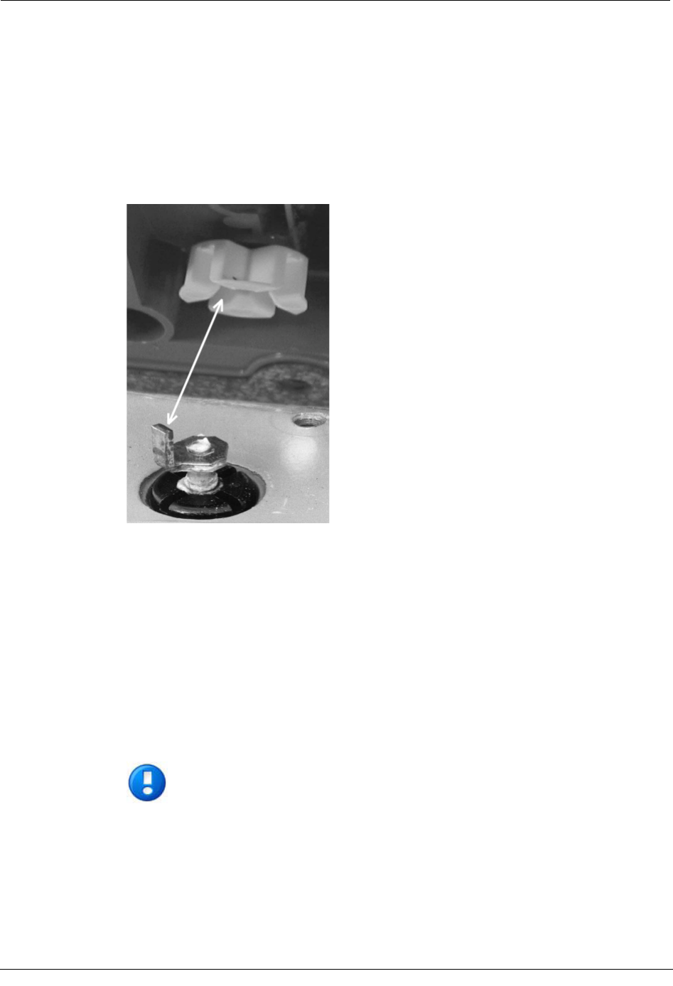
1. Turn the white wriggler so one of its four drive slots lines up with the drive dog.
2. Gently place the 100G ERT Module on the meter.
If there is a gap between the gasket and the meter, it is probably because the drive slot
of the ERT module assembly's wriggler is not properly aligned with the meter
wriggler drive dog. To correct this, remove the assembly and repeat the alignment
procedure in step one.
3. WARNING! If the drive slot of the 100G ERT Module wriggler is not properly
aligned with the meter wriggler drive dog, there may be a gap between the gasket and
the meter. To correct this, remove the assembly and repeat the alignment procedure.
Failure to place the drive post into the drive slot can cause binding and lead to poor
registration or meter failure. Turn each screw 1/4 to 1/2 turn after it contacts the cover.
IMPORTANT Meter manufacturers should torque the mounting screws 15 to 20
inch-pounds.