Itron 100WD AMR Transceiver device for utility meters User Manual P1
Itron Inc AMR Transceiver device for utility meters Users Manual P1
UserManual.wiki
>
Itron
>
100WD User Manual
>
Users Manual P1
Contents
1.
Users Guide 1
2.
Users Guide 2
3.
Users Guide 3
4.
Installation Guide 1
5.
Installation Guide 2
6.
Installation Guide 3
7.
Users Manual 1
8.
Users Manual 2
9.
Users Manual 3
10.
Installation guide 1
11.
Installation guide 2
12.
Installation guide 3
13.
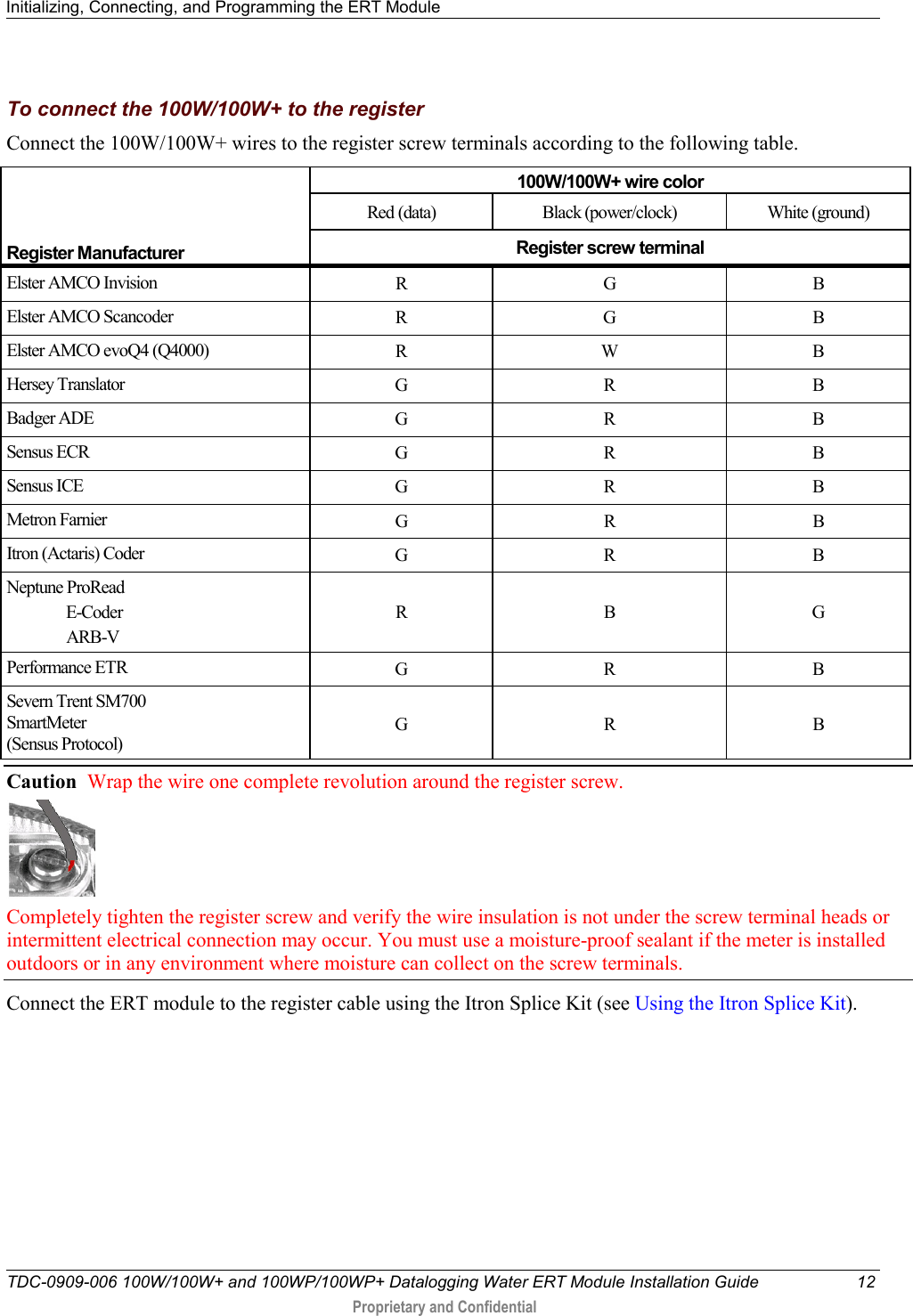
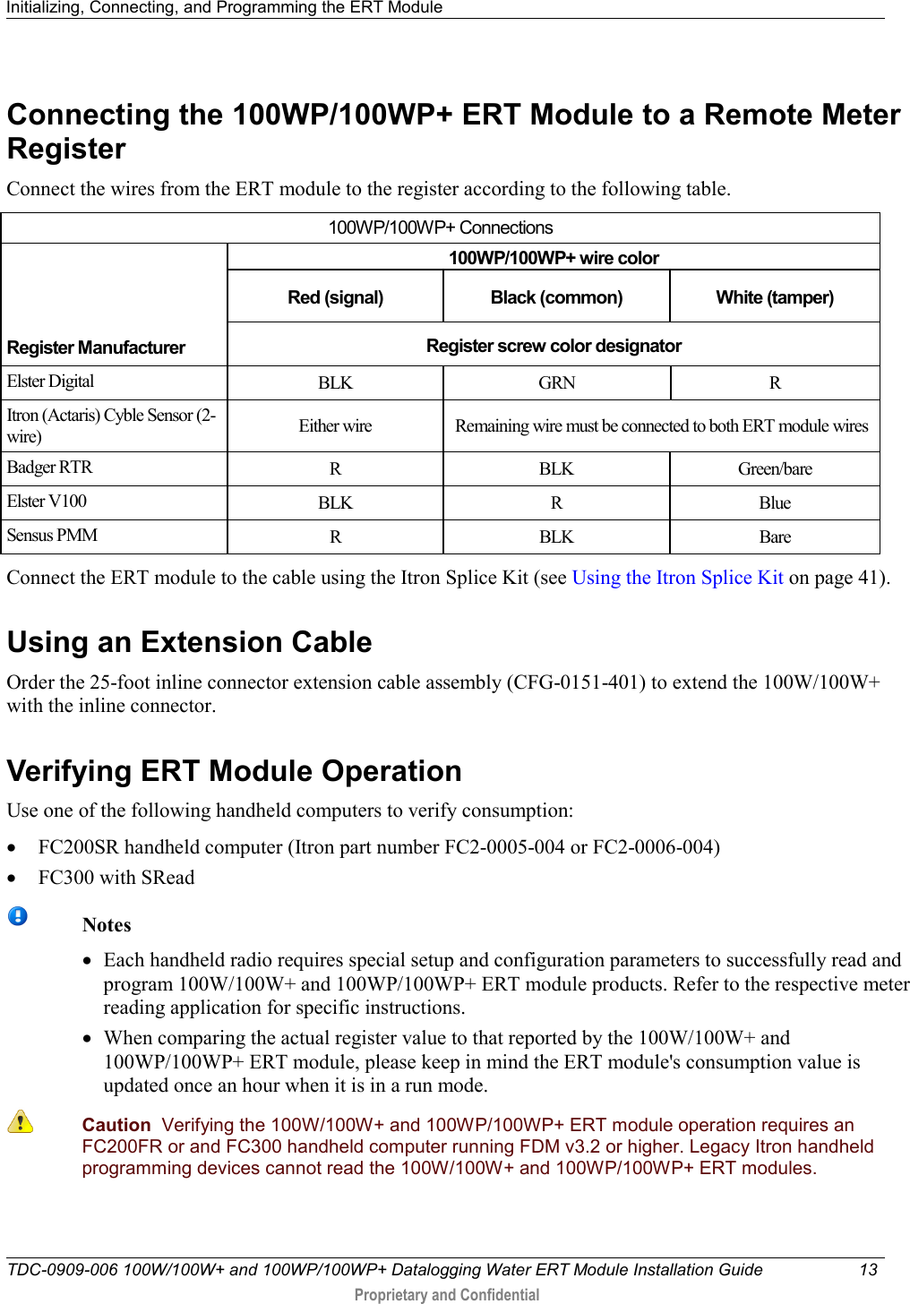
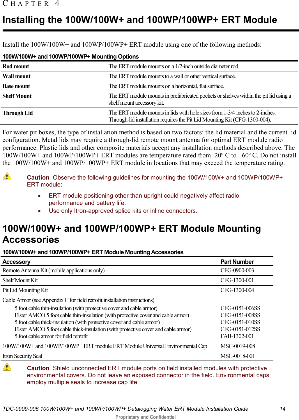
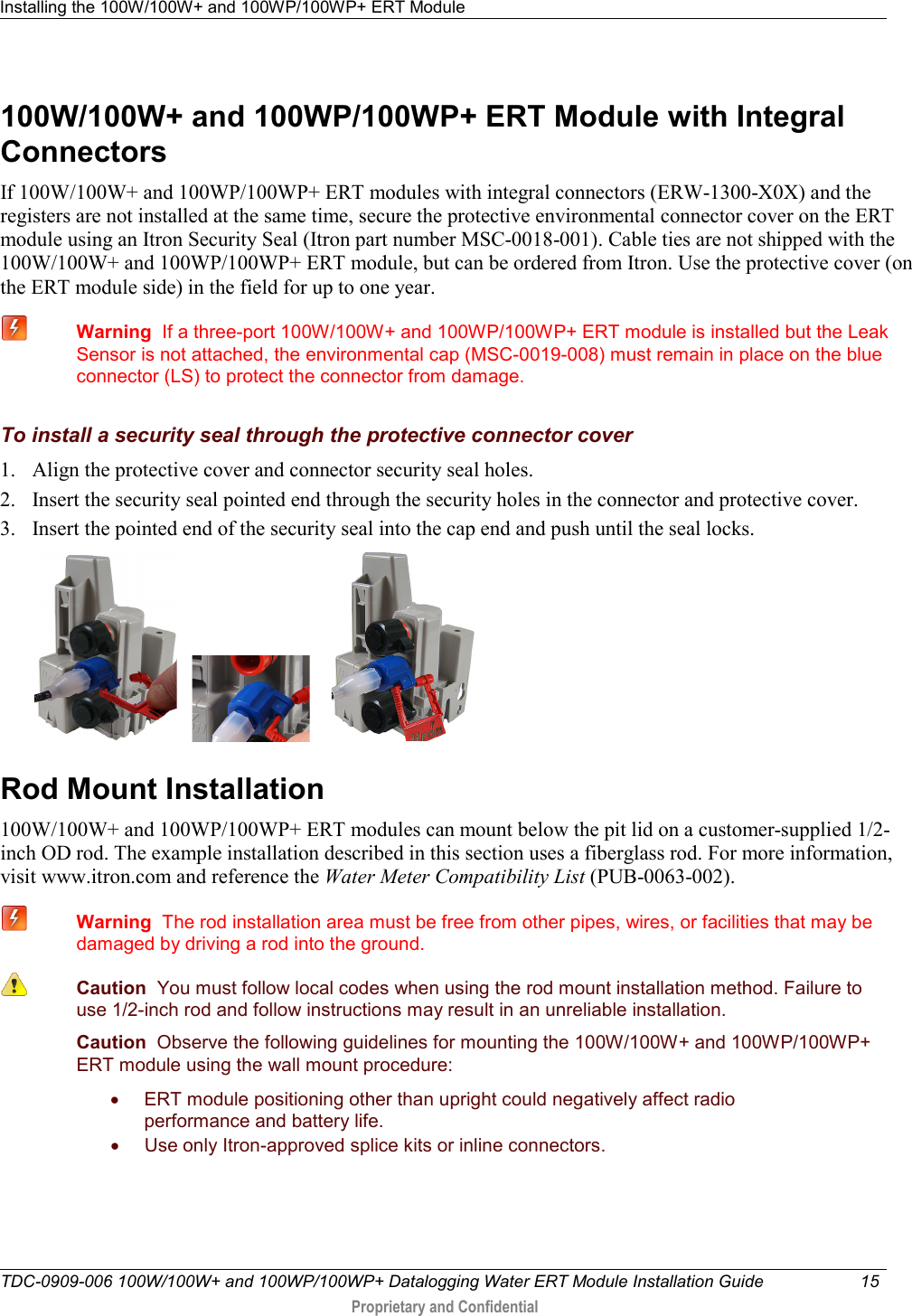
Users Manual P1
14.
Users Manual P2
15.
Users Manual P3
Users Manual P1
Navigation menu
Upload a User Manual
Namespaces
Wiki Guide
HTML
PDF
Info
Views
User Manual
Discussion / Help
Navigation