Itron 100WD AMR Transceiver device for utility meters User Manual P1
Itron Inc AMR Transceiver device for utility meters Users Manual P1
Itron >
Contents
Users Manual P1

Water Solutions
100W/100W+ and 100WP/100WP+ Datalogging
Water ERT Module Installation Guide
TDC-0909-006

TDC-0909-006 100W/100W+ and 100WP/100WP+ Datalogging Water ERT Module Installation Guide ii
Proprietary and Confidential
Identification
100W/100W+ and 100WP/100WP+ Datalogging Water ERT Module Installation Guide
22 January 2013 TDC-0909-006
100W/100W+ and 100WP/100WP+ ERT module
Copyright
© 2010 - 2013 Itron, Inc. All rights reserved.
Confidentiality Notice
The information contained herein is proprietary and confidential and provided subject to the condition that (i) it is held in confidence except to the extent required otherwise by law and (ii) it is
used only for the purposes described herein. Any third party given access to this information is similarly bound in writing.
Compliance Statement
This device complies with Part 15 of the FCC Rules. These limits are designed to provide reasonable protection against harmful interference in a residential installation. Operation is subject to
the following two conditions:
• This device may not cause harmful interference.
• This device must accept any interference that may cause undesirable operation.
This device must be permanently mounted such that it retains a distance of 20 centimeters (7.9 inches) from all persons in order to comply with FCC RF exposure levels.
This equipment has been tested and found to comply with the limits for a Class B digital device, pursuant to Part 15 of the FCC Rules. These limits are designed to provide reasonable
protection against harmful interference in a residential installation. This equipment generates, uses, and can radiate radio frequency energy and, if not installed and used in accordance with the
instructions, may cause harmful interference to radio communications. However, there is no guarantee that interference will not occur in a particular installation.
If this equipment does cause harmful interference to radio or television reception, which can be determined by turning the equipment off and on, the user is encouraged to try to correct the
interference by one or more of the following measures:
• Reorient or relocate the receiving antenna.
• Increase the separation between the equipment and receiver.
• Connect the equipment into an outlet on a circuit different from that to which the receiver is connected.
• Consult the dealer or an experienced radio or TV technician for help.
Compliance Statement
This equipment complies with policies RSS-210 and RSS-GEN of the Industry Canada rules.
Operation is subject to the following two conditions:
• (1) this device may not cause interference, and
• (2) this device must accept any interference, including interference that may cause
undesired operation of the device.
Déclaration de conformité
Le présent appareil est conforme aux CNR d'Industrie Canada applicables aux appareils radio
exempts de licence. L'exploitation est autorisée aux deux conditions suivantes :
• (1) l'appareil ne doit pas produire de brouillage, et
• (2) l'utilisateur de l'appareil doit accepter tout brouillage radioélectrique subi, même
si le brouillage est susceptible d'en compromettre le fonctionnement.
Compliance Statement Canada
Under Industry Canada regulations, this radio transmitter may only operate using an antenna of a
type and maximum (or lesser) gain approved for the transmitter by Industry Canada. To reduce
potential radio interference to other users, the antenna type and its gain should be so chosen that
the equivalent isotropically radiated power (e.i.r.p.) is not more than that necessary for successful
communication.
Déclaration de Conformité
Conformément à la réglementation d'Industrie Canada, le présent émetteur radio peut
fonctionner avec une antenne d'un type et d'un gain maximal (ou inférieur) approuvé pour
l'émetteur par Industrie Canada. Dans le but de réduire les risques de brouillage
radioélectrique à l'intention des autres utilisateurs, il faut choisir le type d'antenne et son gain
de sorte que la puissance isotrope rayonnée équivalente (p.i.r.e.) ne dépasse pas l'intensité
nécessaire à l'établissement d'une communication satisfaisante.
Trademark Notice
Itron is a registered trademark of Itron, Inc.
All other product names and logos in this documentation are used for identification purposes only and may be trademarks or registered trademarks of their respective companies.
Warning To prevent ignition of flammable or combustible atmospheres, disconnect power
before servicing.
Warning Follow these procedures to avoid injury to yourself or others:
• The lithium battery may cause a fire or chemical burn if it is not disposed of
properly.
• Do not recharge, disassemble, heat above 100° Celsius (212° Fahrenheit),
crush, expose to water, or incinerate the lithium battery. Fire, explosion, and
severe burn hazard.
• Keep the lithium battery away from children.
• Replace the lithium battery only with batteries meeting Itron specifications.
Any other battery may cause a fire or explosion.
Warning ELECTROMAGNETIC COMPATIBILITY
Use only approved accessories with this equipment. Unapproved modifications or operation
beyond or in conflict with these instructions for use may void authorization by the authorities
to operate the equipment.
Warning This unit cannot be modified and is not repairable. Attempts to modify or repair
this device will void the warranty.

TDC-0909-006 100W/100W+ and 100WP/100WP+ Datalogging Water ERT Module Installation Guide iii
Proprietary and Confidential
Transportation Classification
The Federal Aviation Administration prohibits operating transmitters and receivers on all commercial aircraft. When powered, ERT modules are considered operating transmitters and receivers
and cannot be shipped by air. All product returns must be shipped by ground transportation to Itron.
Suggestions
If you have comments or suggestions on how we may improve this documentation, send them to TechnicalCommunicationsManager@itron.com
If you have questions or comments about the software or hardware product, contact Itron Technical Support:
Contact
• Internet: www.itron.com
• E-mail: support@itron.com
• Phone: 800 635 8725

TDC-0909-006 100W/100W+ and 100WP/100WP+ Datalogging Water ERT Module Installation Guide iv
Proprietary and Confidential

TDC
-0909-006 100W/100W+ and 100WP/100WP+ Datalogging Water ERT Module Installation Guide v
Proprietary and Confidential
Chapter 1 Before You Begin ........................................................................................ 1
Document Conventions ....................................................................................................................... 1
Document Purpose .............................................................................................................................. 1
How This Document is Organized ....................................................................................................... 1
Related Documents ............................................................................................................................. 2
Chapter 2 About the 100W/100W+ and 100WP/100WP+ ERT Module ...................... 3
100W/100W+ and 100WP/100WP+ ERT Module Models .................................................................. 4
Itron Security Manager (ISM) .............................................................................................................. 6
Enabling 100W+ and 100WP+ ERT Module Security ........................................................................ 6
Battery Life .......................................................................................................................................... 6
100W/100W+ and 100WP/100WP+ ERT Module Transmission Modes ............................................ 7
100W/100W+ Operating Modes .......................................................................................................... 7
100WP/100WP+ Operating Modes ..................................................................................................... 8
100W+ and 100WP+ ERT Module Geo Mode .................................................................................... 9
Chapter 3 Initializing, Connecting, and Programming the ERT Module ................ 10
Initializing the 100W/100W+ ERT Module ........................................................................................ 10
100W/100W+ Encoder ERT Module Start-up ................................................................................... 10
Programming the 100WP/100WP+ ERT Module .............................................................................. 11
100WP/100WP+ Pulser ERT Module Start-up ................................................................................. 11
Connecting to a Meter Register Using the Inline Connector ............................................................. 11
Connecting to a Meter Register Using a Cable ................................................................................. 11
Connecting the 100WP/100WP+ to a Remote Meter Register ......................................................... 13
Using an Extension Cable ................................................................................................................. 13
Verifying 100W/100W+ and 100WP/100WP+ ERT Module Operation ............................................ 13
Chapter 4 Installing the 100W/100W+ and 100WP/100WP+ ERT Module ............... 14
100W/100W+ and 100WP/100WP+ ERT Module Mounting Accessories ........................................ 14
100W/100W+ and 100WP/100WP+ ERT Module with Integral Connectors .................................... 15
Rod Mount Installation ....................................................................................................................... 15
Required Tools and Hardware .......................................................................................................... 16
Wall Mount Installation ...................................................................................................................... 18
Required Mounting Tools and Hardware .......................................................................................... 18
100W/100W+ and 100WP/100WP+ ERT Module Installation in a New Lid ..................................... 20
Base Mount Installation ..................................................................................................................... 20
Required Mounting Tools and Hardware .......................................................................................... 20
Shelf Mount Installation ..................................................................................................................... 21
Required Hardware ........................................................................................................................... 22
Through Lid Installation ..................................................................................................................... 23
Through Lid Mount Required Tools and Hardware ...................................................... 24
Optional Leak Sensor Installation ................................................................................. 27
Contents

Contents
TDC
-0909-006 100W/100W+ and 100WP/100WP+ Datalogging Water ERT Module Installation Guide vi
Proprietary and Confidential
Chapter 5 Optional Direct Connect Remote Antenna Installation .......................... 34
100W/100W+ and 100WP/100WP+ ERT Module Models for use with Remote Antennas .............. 34
Industry Canada Conformity ............................................................................................................. 35
Installing the Remote Antenna .......................................................................................................... 35
Appendix A Using an Inline Connector .................................................................... 39
Appendix B Using the Itron Splice Kit ...................................................................... 41
Appendix C Using the Itron Cable Armor ................................................................. 44
Required Materials ............................................................................................................................ 44
Appendix D Troubleshooting .................................................................................... 46
Index ............................................................................................................................. 47
TDC
-0909-006 100W/100W+ and 100WP/100WP+ Datalogging Water ERT Module Installation Guide 1
Proprietary and Confidential
Document Conventions
Convention
Example
Itron product part numbers are noted in
parentheses.
To install the ERT module (ERW-1300-XXX), do the following steps.
Hypertext links are in blue. See How The Document is Organized on page 1 for document structure information.
Note A Note indicates neutral or positive information that stresses or supplements important points of the
main text. A note supplies information that may apply only in special cases.
Caution A Caution advises users that failure to take or avoid a specified action could result in a loss of
data.
Warning A Warning advises users that failure to take or avoid a specified action could result in physical
harm to the user or the hardware.
Document Purpose
This document provides the installation instructions for the 100W/100W+ and 100WP/100WP+. Mounting
options for the 100W/100W+ and 100WP/100WP+ ERT module include rod mount, wall mount, through-lid
(remote antenna), and shelf-mount installation. For available model configuration, see 100W/100W+ and
100WP/100WP+ ERT Module Models on page 4.
An optional Itron Leak Sensor is available for all three configurations to provide leak monitoring capability.
100W/100W+ and 100WP/100WP+ ERT module configurations provide an easy interface to several register
types. The 20-inch cable variant allows meter manufacturers to mount the ERT module directly to their
respective meter registers before delivery to the installer.
Caution Installing an integrated 100W/100W+ and 100WP/100WP+ ERT module and meter register in a
water pit box reduces the ERT module's RF signal distance significantly. If read reliability is a problem,
install a remote antenna or select a new installation method.
How This Document is Organized
This document is organized into the following chapters:
Chapter
Description
1. Before You Begin Information about this publication.
2. About the 100W/100W+ and 100WP/100WP+ ERT
Module
Overview of 100W/100W+ and 100WP/100WP+ ERT module
installation.
3. Initializing, Connecting, and Programming the ERT
Module
Instructions to initialize the 100W/100W+ ERT module, program the
100WP/100WP+ ERT module, and connect the ERT modules to the
water meter.
CHAPTER 1
B
efore You Begin

Before You Begin
TDC
-0909-006 100W/100W+ and 100WP/100WP+ Datalogging Water ERT Module Installation Guide 2
Proprietary and Confidential
Chapter
Description
4. Installing the 100W/100W+ and 100WP/100WP+ ERT
Module
Step-by-step ERT module installation instructions for:
• Rod mount
• Wall mount
• Base mount
• Shelf mount (kit CFG-1300-001)
• Through lid mount
• Optional Leak Sensor installation
5. Optional Direct Connect Remote Antenna Installation Instructions for installing the optional remote antenna.
Appendix A Using an Inline Connector Instructions for installing an inline connector.
Appendix B Using the Itron Splice Kit Instructions for installing the Itron Splice Kit.
Appendix C Optional Armor Cable Installation Instructions for installing the optional armor cable.
Appendix D Troubleshooting Troubleshooting 100W/100W+ and 100WP/100WP+ ERT module
operation.
Related Documents
Document Description
Itron Part Number
100 Series Modules and CENTRON Bridge Meter Tamper Reference Guide
TDC-1028-XXX
Field Deployment Manager Endpoint Tools Mobile Application Guide TDC-0934-XXX
Field Deployment Manager Field Representative's Guide TDC-0936-XXX
900 MHz Belt-Clip Radio User's Guide TDC-0889-XXX
FC300 Getting Started Guide
TDC-0898-XXX
FC200 Series Getting Started Guide TDC-0598-XXX
Water ERT Module Ordering Guide PUB-0063-001
Water Meter Compatibility List PUB-0063-002
mlogonline™ Network Leak Monitoring System User Guide TDC-0792-XXX
Note XXX designates the document revision and is subject to change without
notice.

TDC
-0909-006 100W/100W+ and 100WP/100WP+ Datalogging Water ERT Module Installation Guide 3
Proprietary and Confidential
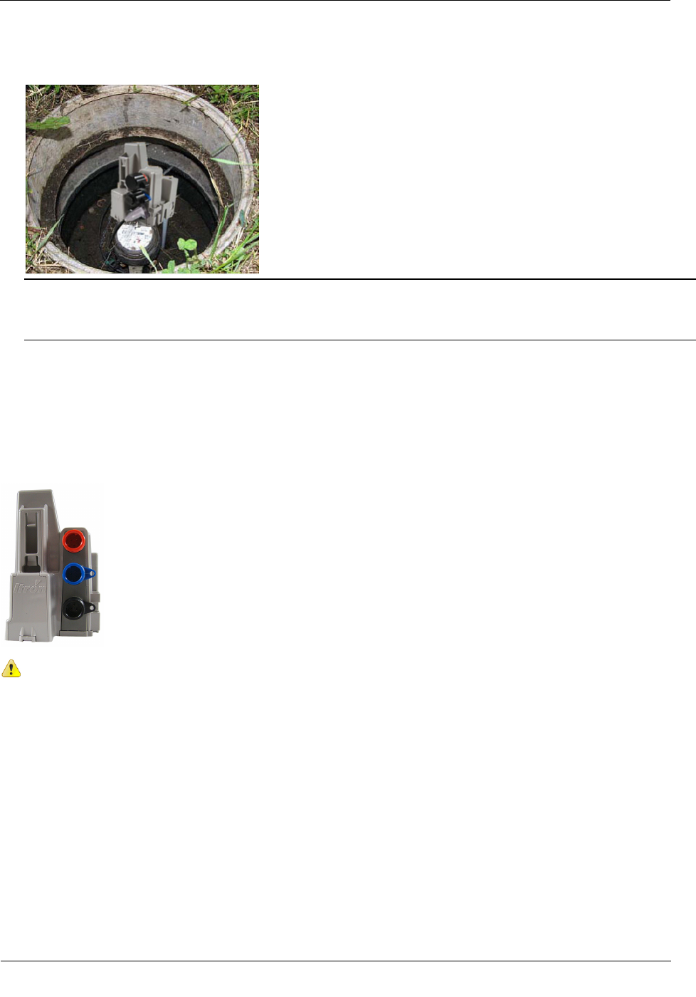
The 100W/100W+ and 100WP/100WP+ ERT modules are high-power radio frequency automatic meter
reading (AMR) devices that attach to water registers to collect consumption usage and tamper data the ERT
module then transmits to a data collection device. The ERT module operates in both bubble-up mode and two-
way mode.
The 100W/100W+ and 100WP/100WP+ ERT modules ship in factory mode. After installation and
programming, the ERT modules acquire and transmit meter register data. The ERT module transfers meter
data immediately if the unit is initialized or programmed with a handheld computer during installation (see
Initializing, Connecting, and Programming the ERT Module).
The 100W/100W+ and 100WP/100WP+ ERT modules support protocols for a variety of meter manufacturer's
registers. Refer to the Water Meter Compatibility List (PUB-0063-002), for the list of supported meters and
registers.
The 100W/100W+ and 100WP/100WP+ ERT modules are capable of reading 9-digit registers. The
100W/100W+ may be programmed to truncate up to three digits. Field Deployment Manager (FDM) provides
the programming tool to set the 100W/100W+ for your register's dial parameters.
100W/100W+ and 100WP/100WP+ ERT modules feature the following capabilities:
• Leak Detection and Reverse Flow Detection. The 100W/100W+ and 100WP/100WP+ ERT modules
feature robust features that provide Leak Detection and Reverse Flow Detection. For more information
about Leak Detection and Reverse Flow Detection, see the Itron white paper, Detecting Leaks and
Reverse Flow with 100W Series ERT Modules.
• (Optional) Leak Sensor or Remote Water Shut-off (SO).
• Itron Leak Sensors (LS) analyze water flow sound patterns to detect new, evolving, and preexisting
water leaks. LS analysis data is uploaded to mlogonline Network Leak Monitoring for data analysis.
Systems with optional LS devices access leak information through a utility-specific, secure
mlogonline portal.
CHAPTER 2
A
bout the 100W/100W+ and 100WP/100WP+ ERT Module

About the 100W/100W+ and 100WP/100WP+ ERT Module
TDC
-0909-006 100W/100W+ and 100WP/100WP+ Datalogging Water ERT Module Installation Guide 4
Proprietary and Confidential
Communication Error Indicators.
• Last Good Read (LGR Flag) Indicates a communication error with the register.
• 100W/100W+ encoder ERT module
If this flag is set for 24 consecutive hours, it initiates a cut cable flag in the extended tampers.
The LGR Flag automatically clears after the ERT module receives a successful read from the
register.
• 100WP pulser ERT module
If the LGR Flag is set two consecutive times, it initiates a Cut Cable Flag in the extended tampers.
The LGR Flag automatically clears after the ERT module receives a successful read from the
register.
Note Last Good Read Flag may be an indicator of a damaged register.
• Extended Tamper Flag (retrievable with two-way communication)
• Low Battery Warning. The 100W/100W+ and 100WP/100WP+ ERT modules include a battery
life estimator. The estimator is based on the number of data packets sent at the various power
levels and the age (self-discharge) of the ERT module. The low battery warning allows the utility
to easily identify which ERT modules are nearing end-of-life in a mixed population and gives the
opportunity to schedule replacement.
Note The low battery warning is a single flag set when the battery has less than 10% remaining
capacity, typically 2 years life remaining. Battery life is evaluated daily at midnight.
• Cut Cable Flag
• 100W/100W+ encoder ERT module. The Cut Cable Flag sets if the LGR Flag is active for 24
hours.
• 100WP/100WP+ pulser ERT module. The Cut Cable Flag sets if the LGR Flag is active two
consecutive times.
• The Cut Cable Flag remains active for 40 days in Mobile mode.
• The Cut Cable Flag remains active for 24 hours in Fixed Network mode.
100W/100W+ and 100WP/100WP+ ERT Module Models
100W/100W+ and 100WP/100WP+ ERT Module Description Itron Part
Number
100W encoder, dual-port direct connect remote antenna and register integral connectors ERW-1300-202
100W+ encoder, dual-port direct connect remote antenna and register integral connectors, ISM ERW-1300-302
100W encoder, three-port direct connect remote antenna, Leak Sensor, and register integral connectors ERW-1300-203
100W+ encoder, three-port direct connect remote antenna, Leak Sensor, and register integral connectors, ISM ERW-1300-303
100W encoder, 5-ft. cable register connect, direct connect remote antenna integral connector ERW-1300-205
100W+ encoder, 5-ft. cable register connect, direct connect remote antenna integral connector, ISM ERW-1300-305
100W encoder 5-ft. cable register connect, direct connect remote antenna and Leak Sensor integral connectors ERW-1300-206
100W+ encoder 5-ft. cable register connect, direct connect remote antenna and Leak Sensor integral
connectors, ISM
ERW-1300-306
100W encoder, 20-in. cable register connect, direct connect remote antenna integral connector ERW-1300-217

About the 100W/100W+ and 100WP/100WP+ ERT Module
TDC
-0909-006 100W/100W+ and 100WP/100WP+ Datalogging Water ERT Module Installation Guide 5
Proprietary and Confidential
100W/100W+ and 100WP/100WP+ ERT Module Description Itron Part
Number
100W+ encoder, 20-in. cable register connect, direct connect remote antenna integral connector, ISM ERW-1300-317
100W encoder, 20-in. cable register connect, direct connect remote antenna, and Leak Sensor or integral
connectors
ERW-1300-218
100W+ encoder, 20-in. cable register connect, direct connect remote antenna, and Leak Sensor or integral
connectors, ISM
ERW-1300-318
100WP pulser dual-port direct connect remote antenna and register integral connectors ERW-1300-208
100WP+ pulser dual-port direct connect remote antenna and register integral connectors ERW-1300-308
100WP pulser, three-port direct connect remote antenna, Leak Sensor, and register integral connectors ERW-1300-209
100WP+ pulser, three-port direct connect remote antenna, Leak Sensor, and register integral connectors, ISM ERW-1300-309
100WP pulser, 5-ft. cable, direct connect remote antenna integral connector ERW-1300-211
100WP+ pulser, 5-ft. cable, direct connect remote antenna integral connector, ISM ERW-1300-311
100WP Pulser, 5-ft. cable, direct connect remote antenna and Leak Sensor integral connectors ERW-1300-212
100WP+ Pulser, 5-ft. cable, direct connect remote antenna and Leak Sensor integral connectors, ISM ERW-1300-312
100WP pulser, 20-in. cable register connect, direct connect remote antenna integral connector ERW-1300-219
100WP+ pulser, 20-in. cable register connect, direct connect remote antenna integral connector ERW-1300-319
100W pulser, 20-in. cable register connect, direct connect remote antenna, and Leak Sensor integral connectors ERW-1300-220
100W+ pulser, 20-in. cable register connect, direct connect remote antenna, and Leak Sensor integral
connectors
ERW-1300-320
Note The 100W/100W+ and 100WP/100WP+ ERT module works accurately with
cable lengths up to 300 feet.

About the 100W/100W+ and 100WP/100WP+ ERT Module
TDC
-0909-006 100W/100W+ and 100WP/100WP+ Datalogging Water ERT Module Installation Guide 6
Proprietary and Confidential
Itron Security Manager (ISM)
Users have the option of enabling the ISM enhanced security in the 100W+ and 100WP+ ERT module. ISM
is a component of a ChoiceConnect system. ChoiceConnect system security applies to the RF
communications between the handheld computer, Mobile Collector, or Fixed Network system and the ERT
module. There are two fundamental security processes used in the ChoiceConnect system to ensure
confidentiality and validity of the system communications.
• Authentication. Authentication is the process of confirming that an artifact is genuine or valid.
Authentication in the 100W+ and 100WP+ ERT module is the process of verifying a request is from a
valid source and in its original form.
• Encryption. Encryption is the process of transforming information to make it unreadable to anyone who
does not have a valid security key. There are two types of encryption, symmetric and asymmetric.
Symmetric encryption uses a shared key to decrypt or encrypt information. Asymmetric encryption uses a
private key to encrypt and a public key to decrypt.
As a component of the Itron ChoiceConnect solution, the 100W+ and 100WP+ ERT module supports the
security model found in the ChoiceConnect solution for both reading and programming. If the 100W+ and
100WP+ ERT modules are shipped without ChoiceConnect security enabled, the utility can, at a later date,
configure the ERT modules for security.
Enabling 100W+ and 100WP+ ERT Module Security
When 100W+ and 100WP+ ERT modules ship from an Itron factory, each module contains a utility factory
key. The presence of this utility factory key does not enable security. The installer enables 100W+ and
100WP+ ERT module security using an Itron programming device and programming commands. Initial key
exchange commands are secured using the utility factory key. For more information about programming the
100W+ and 100WP+ ERT module, see the FDM Endpoint Tools Mobile Application Guide (TDC-0934).
Battery Life
Powered by two non-replaceable, long-life lithium batteries, the 100W/100W+ and 100WP/100WP+ ERT
modules have an expected battery life of 20 years when the ERT modules operate in default mobile or fixed
network operating mode. If the 100W/100W+ and 100WP/100WP+ ERT module is programmed for hard to
read mobile mode, the battery life is reduced to 12 years. To pro-actively indicate the battery has reached a
<10% useful battery life, a Low Battery Flag is set to indicate a low battery warning and alert the utility of an
impending battery failure.

About the 100W/100W+ and 100WP/100WP+ ERT Module
TDC
-0909-006 100W/100W+ and 100WP/100WP+ Datalogging Water ERT Module Installation Guide 7
Proprietary and Confidential
100W/100W+ and 100WP/100WP+ ERT Module Transmission
Modes
The 100W/100W+ and 100WP/100WP+ ERT module can be set to transmit in fixed network, mobile high
power, mobile and handheld, or hard to read mobile and handheld mode.
• Fixed Network Mode. The 100W/100W+ and 100WP/100WP+ ERT module transmits a high-powered
NIM RF message every six minutes and a contingency SCM+ RF message every minute.
• Mobile and Handheld Mode. The 100W/100W+ and 100WP/100WP+ ERT module transmits a
medium-powered SCM+ RF message every 9 seconds.
• (Optional) Mobile High Power Mode. The 100W/100W+ and 100WP/100WP+ ERT module transmits
a high-powered SCM+ RF message every 60 seconds.
• (Optional) Hard to Read Mobile Mode. The 100W/100W+ and 100WP/100WP+ ERT module
transmits a high-powered SCM+ RF message every 30 seconds. The hard-to-read mobile and handheld
mode should only be used for exceptionally hard-to-read applications.
Note The 100W/100W+ and 100WP/100WP+ ERT module's battery life is significantly affected in hard
to read mobile mode. You may use the 900 MHz Remote Antenna to increase reading range.
An FCC license is not required to read 100W/100W+ and 100WP/100WP+ ERT modules.
100W/100W+ ERT Module Operating Modes
The 100W/100W+ ERT module has three standard operating modes.
1. Factory Mode
• 100W/100W+s are shipped from the factory in factory mode.
• The module's transmitter is turned off.
• The module's receiver is bubbling-up to listen for a programming command.
• 100W/100W+ encoder models will attempt to read the register every hour.
• Last good read and cut tamper flags may be set when a register is not connected.
• If the 100W/100W+ reads a connected register, the module automatically moves to run mode.

About the 100W/100W+ and 100WP/100WP+ ERT Module
TDC
-0909-006 100W/100W+ and 100WP/100WP+ Datalogging Water ERT Module Installation Guide 8
Proprietary and Confidential
2. Run Mode
• 100W/100W+'s normal operation mode.
• The 100W transmitted message is dependent on its factory settings for standard consumption
messages (SCM), standard consumption + messages (SCM+), or network interval message (NIM).
o For SCM and SCM+, the 100W/100W+ default bubble-up rate is 9 seconds.
o For NIM, the 100W/100W+ default bubble-up rate is 5 minutes. When the ERT module is set
for NIM, the 100W/100W+ transmits a contingency SCM+ message every minute. NIM
mode is configured when the module detects an attached register or by programming NIM
mode with a programming device.
3. Audit Mode
• Audit mode is configured by sending a Check ERT command or a Set Mode command #119 with a
programming device.
• The 100W/100W+ operates as if in run mode but also transmits an SCM/SCM+ message every 4
seconds and bubbles up the receiver every 4 seconds.
• The 100W/100W+ exits audit mode automatically after 1 hour or by configuring run mode with a
programming device.
4. GEO mode
• To reach the head end, the 100W+/100WP+ ERT module establishes a communication link with a
CPU.
• In the event communications are lost with the host CPU, the 100W+/100WP+ ERT module searches
for a nearby link.
• The ERT module establishes communications with the new device and continues transmitting NIM
messages.
100WP/100WP+ ERT Module Operating Modes
The 100WP/100WP+ has four standard operating modes.
1. Factory mode
• 100WP/100WP+s ship from the factory in factory mode.
• The 100WP/100WP+'s transmitter is off.
• The 100WP/100WP+'s receiver bubbles-up to listen for a programming command.
• Last Good Read and Extended Tamper Flags may be set when a register is not connected.
• You must program the 100WP/100WP+ with the initial consumption and the register type to properly
move the ERT module to run mode and record consumption. You can program the 100WP/100WP+ in the
field with Field Deployment Manager (FDM) or in the factory using custom programming.

About the 100W/100W+ and 100WP/100WP+ ERT Module
TDC
-0909-006 100W/100W+ and 100WP/100WP+ Datalogging Water ERT Module Installation Guide 9
Proprietary and Confidential
2. Run mode
• 100WP/100WP+s normal operation mode.
• The 100WP/100WP+ transmitted message is dependent on its factory settings or FDM programming for
standard consumption messages (SCM, SCM+) or network interval message (NIM).
• For SCM/SCM+ (mobile), the 100WP/100WP+ default bubble-up rate is 9 seconds.
• For NIM (fixed network), the 100WP/100WP+ default bubble-up rate is five minutes. When the ERT
module is set for NIM, the 100WP/100WP+ transmits a contingency SCM/SCM+ message every
minute. NIM mode is configured by programming NIM mode with a programming device.
3. Meter manufacturer quiet mode
• Meter manufacturers can configure the 100WP/100WP+ for quiet mode after programming and direct
mounting the 100WP/100WP+ in a factory.
• The 100WP/100WP+ is awakened from quiet mode and enters run mode in one of two ways:
• Counting two pulses. The pulses are counted internal to the 100WP/100WP+ while it is in quiet mode.
• Receiving a two-way command, such as a Read ERT using FDM.
• If an ERT module installed in quiet mode is not bubbling up SCM/SCM+ or NIM messages, it may be due
to zero consumption on the ERT module, such as a vacant or vacation home. Initiate a two-way command
(for example, perform a Read ERT with FDM) before removing the unit.
4. GEO mode
• To reach the head end, 100W/100W+ establishes a communication link with a CPU.
• In the event communications are lost with the host CPU, the 100WP/100WP+ searches for a nearby
link.
• The ERT establishes communications with the new device and continues transmitting NIM messages.
100W+ and 100WP+ ERT Module Geo Mode
100W+ and 100WP+ ERT module geo mode reduces infrastructure requirements by improving network
coverage. The 100W+ an100WP+ ERT module geo mode technology addresses meters with isolated RF
impairments allowing hard-to-read ERT modules to be read by a neighboring ERT module with good network
coverage. The neighboring ERT module forwards the hard-to-read ERT module's message to the nearest data
collection device.

TDC
-0909-006 100W/100W+ and 100WP/100WP+ Datalogging Water ERT Module Installation Guide 10
Proprietary and Confidential
This chapter provides the instructions to initialize and start up the 100W/100W+, program and start up the
100WP/100WP+, and connect the 100W/100W+ or 100WP/100WP+ ERT module.
Initializing the 100W/100W+ ERT Module
Caution To obtain an immediate reading, initialize the 100W/100W+ with an approved handheld
computer. Failure to initialize the ERT module may delay the initial reading up to one hour.
• To initialize the 100W/100W+ immediately, use one of the following handheld computers running Field
Deployment Manager (FDM) version 1.0 or later (100W+ series modules require FDM version 3.2 or
higher).
• FC200SR handheld computer (Itron part number FC2-0005-004 or FC2-0006-004)
• FC300 with SRead
• For normal activation, connect the 100W/100W+ to the water meter register. The ERT module polls for a
register every hour. The 100W/100W+ automatically activates after the ERT module detects a register.
100W/100W+ Encoder ERT Module Start-up
The 100W/100W+ automatically:
• Detects the connected register type at the top of the hour, exits factory mode, and enters run mode
(programming is not required for the 100W/100W+ to initiate run mode in the default mobile mode).
• Detects an Itron Leak Sensor.
100W/100W+ encoder programming is required to:
• Change the operation mode (for example, to change the ERT module from the default mobile mode to
fixed network mode).
• Enter a utility ID or lock type.
• To enter an E-Coder 8-digit driver.
• Commission security
Itron strongly recommends performing a Check ERT with a handheld computer running FDM to verify the
ERT module is operating correctly after installation. Performing a Check ERT will:
• Generate an immediate register read.
• Align the 100W/100W+'s time with the handheld's time.
Important Periodically dock or cradle the handheld computer or mobile reader to keep the time current.
• Verify communication with the Leak Sensor.
• Check for tamper flags.
CHAPTER 3
I
nitializing, Connecting, and Programming the ERT Module

Initializing, Connecting, and Programming the ERT Module
TDC
-0909-006 100W/100W+ and 100WP/100WP+ Datalogging Water ERT Module Installation Guide 11
Proprietary and Confidential
Programming the 100WP/100WP+ ERT Module
Programming the 100WP/100WP+ requires one of the following handheld computers running Field
Deployment Manager (FDM) version 3.2 or later.
• FC200SR handheld computer (Itron part number FC2-0005-004 or FC2-0006-004)
• FC300 with SRead
For normal activation, connect the 100WP/100WP+ to the water meter register and program the ERT module
with FDM.
100WP/100WP+ Pulser ERT Module Start-up
The 100WP/100WP+ enters run mode by completing programming with FDM. Programming sets the
appropriate pulser parameters (initial consumption and utility ID).
Itron strongly recommends performing a Check ERT with a handheld computer running FDM to verify the
100WP/100WP+ is operating correctly after installation. Performing a Check ERT will:
• Generate an immediate register read.
• Align the 100WP/100WP+'s time with the handheld's time.
Important Periodically dock or cradle the handheld computer or mobile reader to keep the time current.
• Verify communication with the Leak Sensor.
• Check for tamper flags.
Connecting to a Meter Register Using the Inline Connector
The inline connector system easily allows a separation between the ERT module and meter register and
provides for general maintenance or system troubleshooting (see Using an Inline Connector on page 39).
Connecting to a Meter Register Using a Cable
You may connect the 100W/100W+ and 100WP/100WP+ ERT module to the water meter register using the
5-foot or 20-inch cable.
Caution ERT module wire terminations must be properly sealed with a non-conductive gel
material to prevent water intrusion (otherwise, this configuration should not be used in a pit box
environment). Itron recommends the 5-foot or 20-inch cable configuration for OEM users only.

Initializing, Connecting, and Programming the ERT Module
TDC
-0909-006 100W/100W+ and 100WP/100WP+ Datalogging Water ERT Module Installation Guide 12
Proprietary and Confidential
To connect the 100W/100W+ to the register
Connect the 100W/100W+ wires to the register screw terminals according to the following table.
Register Manufacturer
100W/100W+ wire color
Red (data) Black (power/clock) White (ground)
Register screw terminal
Elster AMCO Invision R G B
Elster AMCO Scancoder R G B
Elster AMCO evoQ4 (Q4000) R W B
Hersey Translator G R B
Badger ADE G R B
Sensus ECR G R B
Sensus ICE G R B
Metron Farnier G R B
Itron (Actaris) Coder G R B
Neptune ProRead
E-Coder
ARB-V
R B G
Performance ETR G R B
Severn Trent SM700
SmartMeter
(Sensus Protocol)
G
R
B
Caution Wrap the wire one complete revolution around the register screw.
Completely tighten the register screw and verify the wire insulation is not under the screw terminal heads or
intermittent electrical connection may occur. You must use a moisture-proof sealant if the meter is installed
outdoors or in any environment where moisture can collect on the screw terminals.
Connect the ERT module to the register cable using the Itron Splice Kit (see Using the Itron Splice Kit).

Initializing, Connecting, and Programming the ERT Module
TDC
-0909-006 100W/100W+ and 100WP/100WP+ Datalogging Water ERT Module Installation Guide 13
Proprietary and Confidential
Connecting the 100WP/100WP+ ERT Module to a Remote Meter
Register
Connect the wires from the ERT module to the register according to the following table.
100WP/100WP+ Connections
Register Manufacturer
100WP/100WP+ wire color
Red (signal) Black (common) White (tamper)
Register screw color designator
Elster Digital BLK GRN R
Itron (Actaris) Cyble Sensor (2-
wire) Either wire Remaining wire must be connected to both ERT module wires
Badger RTR R BLK Green/bare
Elster V100 BLK R Blue
Sensus PMM R BLK Bare
Connect the ERT module to the cable using the Itron Splice Kit (see Using the Itron Splice Kit on page 41).
Using an Extension Cable
Order the 25-foot inline connector extension cable assembly (CFG-0151-401) to extend the 100W/100W+
with the inline connector.
Verifying ERT Module Operation
Use one of the following handheld computers to verify consumption:
• FC200SR handheld computer (Itron part number FC2-0005-004 or FC2-0006-004)
• FC300 with SRead
Notes
• Each handheld radio requires special setup and configuration parameters to successfully read and
program 100W/100W+ and 100WP/100WP+ ERT module products. Refer to the respective meter
reading application for specific instructions.
• When comparing the actual register value to that reported by the 100W/100W+ and
100WP/100WP+ ERT module, please keep in mind the ERT module's consumption value is
updated once an hour when it is in a run mode.
Caution Verifying the 100W/100W+ and 100WP/100WP+ ERT module operation requires an
FC200FR or and FC300 handheld computer running FDM v3.2 or higher. Legacy Itron handheld
programming devices cannot read the 100W/100W+ and 100WP/100WP+ ERT modules.

TDC
-0909-006 100W/100W+ and 100WP/100WP+ Datalogging Water ERT Module Installation Guide 14
Proprietary and Confidential
Install the 100W/100W+ and 100WP/100WP+ ERT module using one of the following methods:
100W/100W+ and 100WP/100WP+ Mounting Options
Rod mount The ERT module mounts on a 1/2-inch outside diameter rod.
Wall mount The ERT module mounts to a wall or other vertical surface.
Base mount The ERT module mounts on a horizontal, flat surface.
Shelf Mount The ERT module mounts in prefabricated pockets or shelves within the pit lid using a
shelf mount accessory kit.
Through Lid The ERT module mounts in lids with hole sizes from 1-3/4 inches to 2-inches.
Through-lid installation requires the Pit Lid Mounting Kit (CFG-1300-004).
For water pit boxes, the type of installation method is based on two factors: the lid material and the current lid
configuration. Metal lids may require a through-lid remote mount antenna for optimal ERT module radio
performance. Plastic lids and other composite materials accept any installation methods described above. The
100W/100W+ and 100WP/100WP+ ERT modules are temperature rated from -20º C to +60º C. Do not install
the 100W/100W+ and 100WP/100WP+ ERT module in locations that may exceed the temperature rating.
Caution Observe the following guidelines for mounting the 100W/100W+ and 100WP/100WP+
ERT module:
• ERT module positioning other than upright could negatively affect radio
performance and battery life.
•
Use only Itron-approved splice kits or inline connectors.
100W/100W+ and 100WP/100WP+ ERT Module Mounting
Accessories
100W/100W+ and 100WP/100WP+ ERT Module Mounting Accessories
Accessory
Part Number
Remote Antenna Kit (mobile applications only) CFG-0900-003
Shelf Mount Kit CFG-1300-001
Pit Lid Mounting Kit CFG-1300-004
Cable Armor (see Appendix C for field retrofit installation instructions)
5 foot cable thin-insulation (with protective cover and cable armor)
Elster AMCO 5 foot cable thin-insulation (with protective cover and cable armor)
5 foot cable thick-insulation (with protective cover and cable armor)
Elster AMCO 5 foot cable thick-insulation (with protective cover and cable armor)
5 foot cable armor for field retrofit
CFG-0151-006SS
CFG-0151-008SS
CFG-0151-010SS
CFG-0151-012SS
FAB-1302-001
100W/100W+ and 100WP/100WP+ ERT module ERT Module Universal Environmental Cap MSC-0019-008
Itron Security Seal MSC-0018-001
Caution Shield unconnected ERT module ports on field installed modules with protective
environmental covers. Do not leave an exposed connector in the field. Environmental caps
employ multiple seals to increase cap life.
CHAPTER 4
I
nstalling the 100W/100W+ and 100WP/100WP+ ERT Module
Installing the 100W/100W+ and 100WP/100WP+ ERT Module
TDC
-0909-006 100W/100W+ and 100WP/100WP+ Datalogging Water ERT Module Installation Guide 15
Proprietary and Confidential
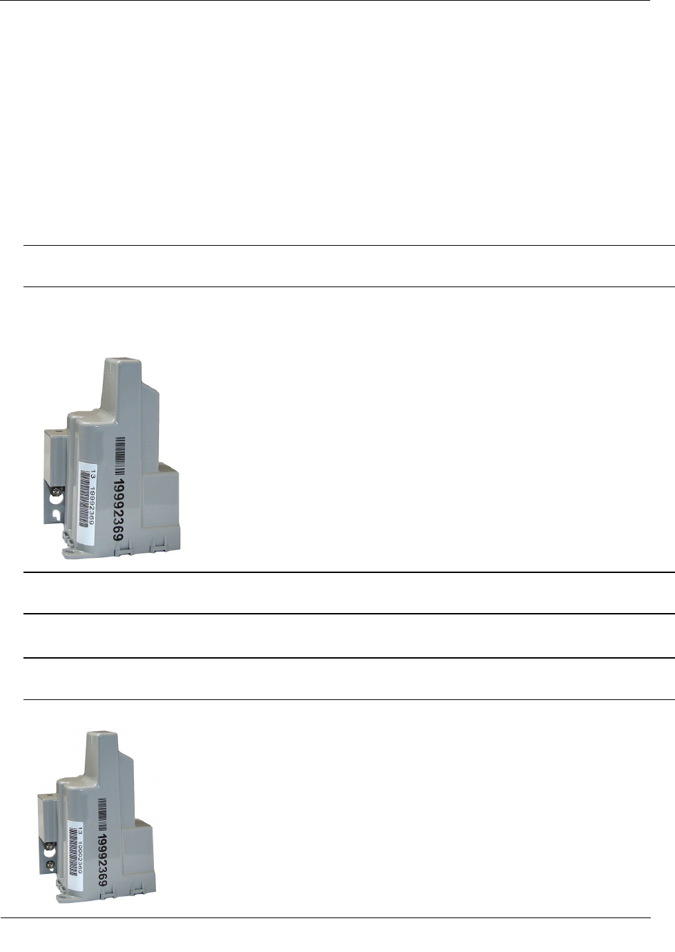
100W/100W+ and 100WP/100WP+ ERT Module with Integral
Connectors
If 100W/100W+ and 100WP/100WP+ ERT modules with integral connectors (ERW-1300-X0X) and the
registers are not installed at the same time, secure the protective environmental connector cover on the ERT
module using an Itron Security Seal (Itron part number MSC-0018-001). Cable ties are not shipped with the
100W/100W+ and 100WP/100WP+ ERT module, but can be ordered from Itron. Use the protective cover (on
the ERT module side) in the field for up to one year.
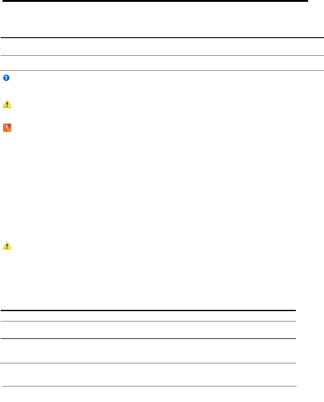
Warning If a three-port 100W/100W+ and 100WP/100WP+ ERT module is installed but the Leak
Sensor is not attached, the environmental cap (MSC-0019-008) must remain in place on the blue
connector (LS) to protect the connector from damage.
To install a security seal through the protective connector cover
1. Align the protective cover and connector security seal holes.
2. Insert the security seal pointed end through the security holes in the connector and protective cover.
3. Insert the pointed end of the security seal into the cap end and push until the seal locks.
Rod Mount Installation
100W/100W+ and 100WP/100WP+ ERT modules can mount below the pit lid on a customer-supplied 1/2-
inch OD rod. The example installation described in this section uses a fiberglass rod. For more information,
visit www.itron.com and reference the Water Meter Compatibility List (PUB-0063-002).
Warning The rod installation area must be free from other pipes, wires, or facilities that may be
damaged by driving a rod into the ground.
Caution You must follow local codes when using the rod mount installation method. Failure to
use 1/2-inch rod and follow instructions may result in an unreliable installation.
Caution Observe the following guidelines for mounting the 100W/100W+ and 100WP/100WP+
ERT module using the wall mount procedure:
• ERT module positioning other than upright could negatively affect radio
performance and battery life.
•
Use only Itron-approved splice kits or inline connectors.
Installing the 100W/100W+ and 100WP/100WP+ ERT Module
TDC
-0909-006 100W/100W+ and 100WP/100WP+ Datalogging Water ERT Module Installation Guide 16
Proprietary and Confidential
Required Tools and Hardware
• Hammer
• 1/2-inch outside diameter rod (you may use either a square or round rod)
• Tape measure
• Rod-driving tool (optional)
• Rod cutting tool
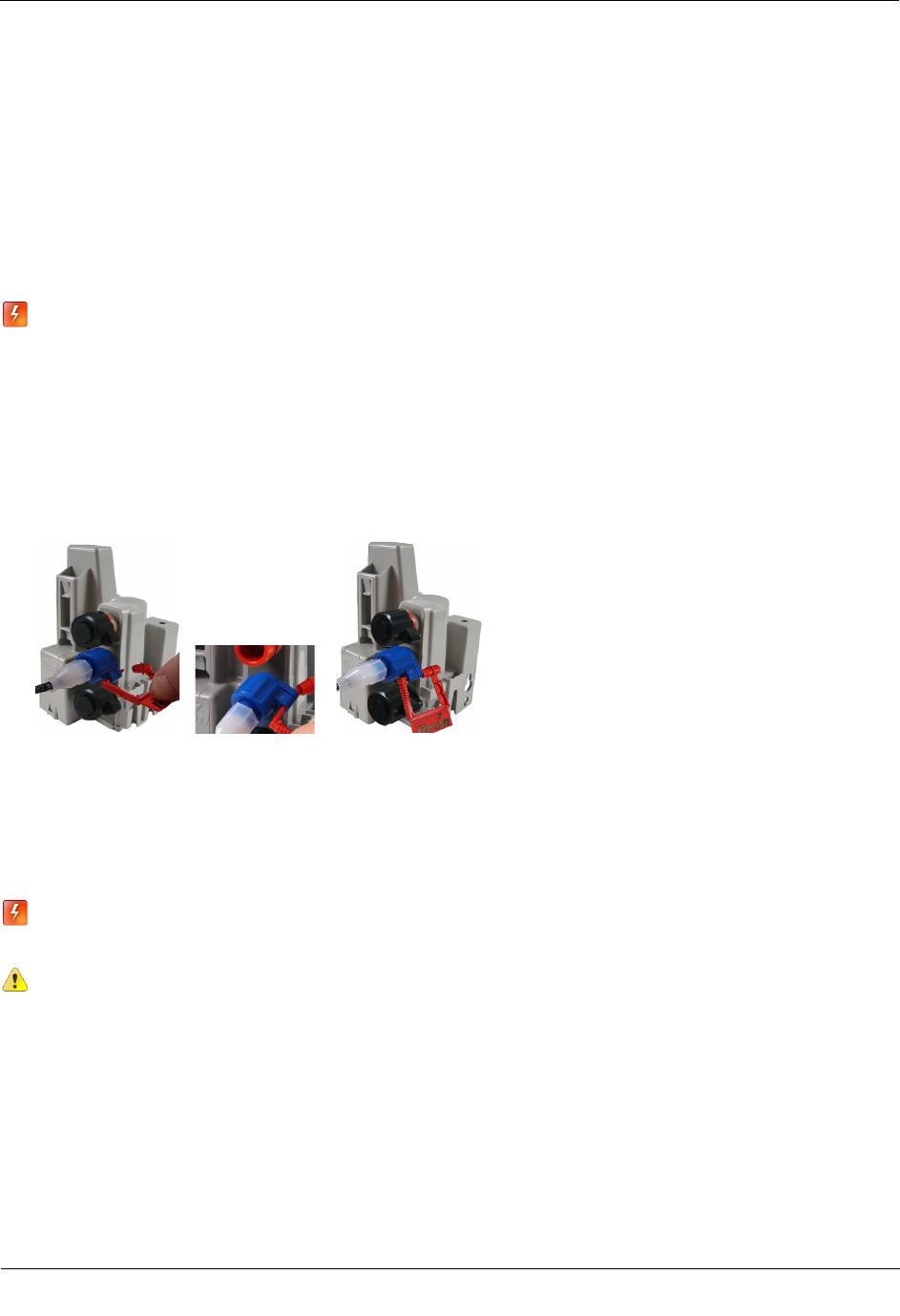
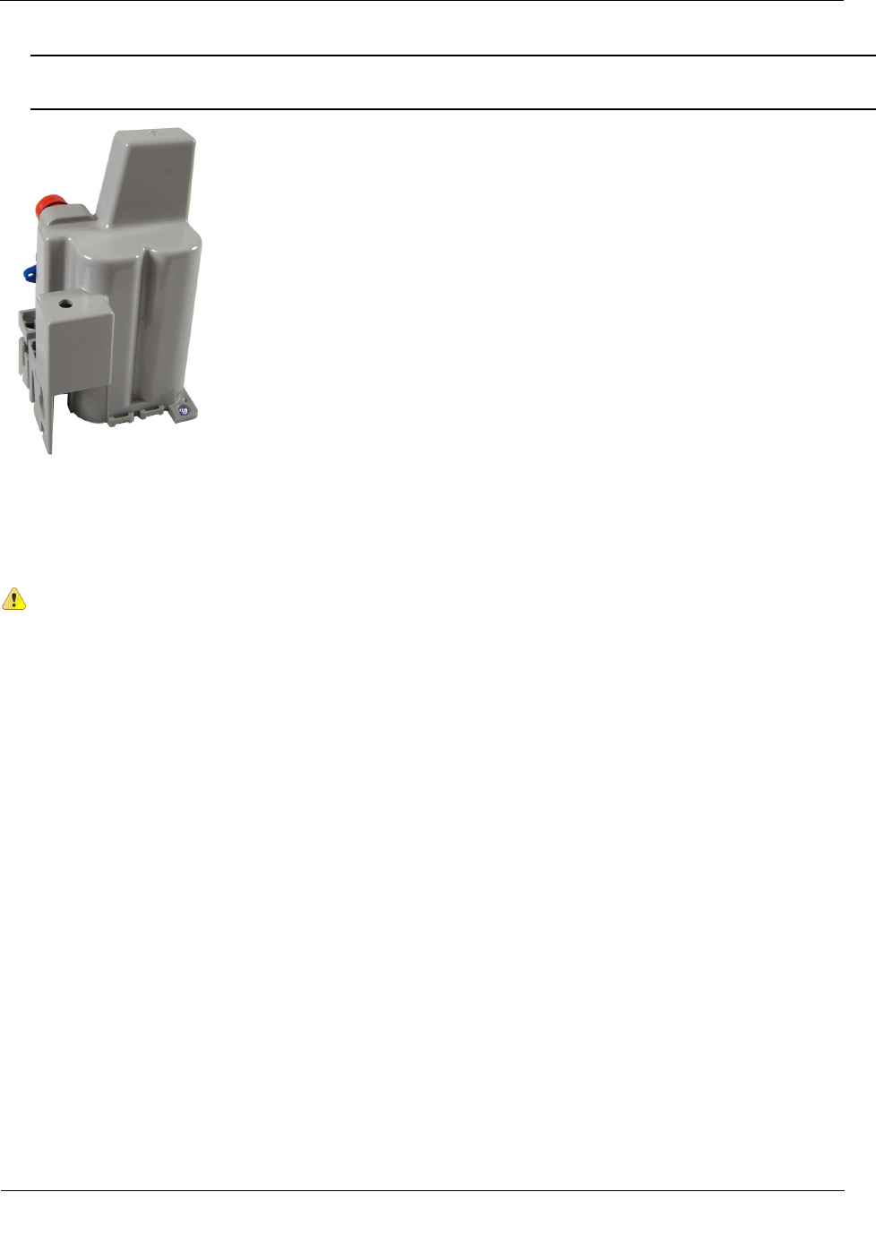
The 1/2-inch diameter rod hole is shown in the following 100W/100W+ and 100WP/100WP+ ERT module
bottom and side views.
To install the 100W/100W+ and 100WP/100WP+ ERT module on a rod
1. Remove the pit lid. Inspect the area to make sure there are no buried cables, pipes, or other obstructions.
2. Measure the pit box depth from the top of the lip (where the lid will rest) to the bottom of the pit. Be sure
to measure the depth at the point where you will drive the rod into the ground.
3. Add 12 inches to the pit box depth measurement taken in step 2. The resulting total represents the
minimum length of rod needed. Soil types and moisture conditions may require longer rod lengths to
ensure the ERT module is well supported and remains vertical.
4. Without touching the meter body or adjacent pipes, position the rod as close to the center of the pit as
possible. Drive the rod into the ground. Ensure the rod remains vertical.
Note The rod shown has an end cap to protect the rod while driving it into the ground.
Installing the 100W/100W+ and 100WP/100WP+ ERT Module
TDC
-0909-006 100W/100W+ and 100WP/100WP+ Datalogging Water ERT Module Installation Guide 17
Proprietary and Confidential
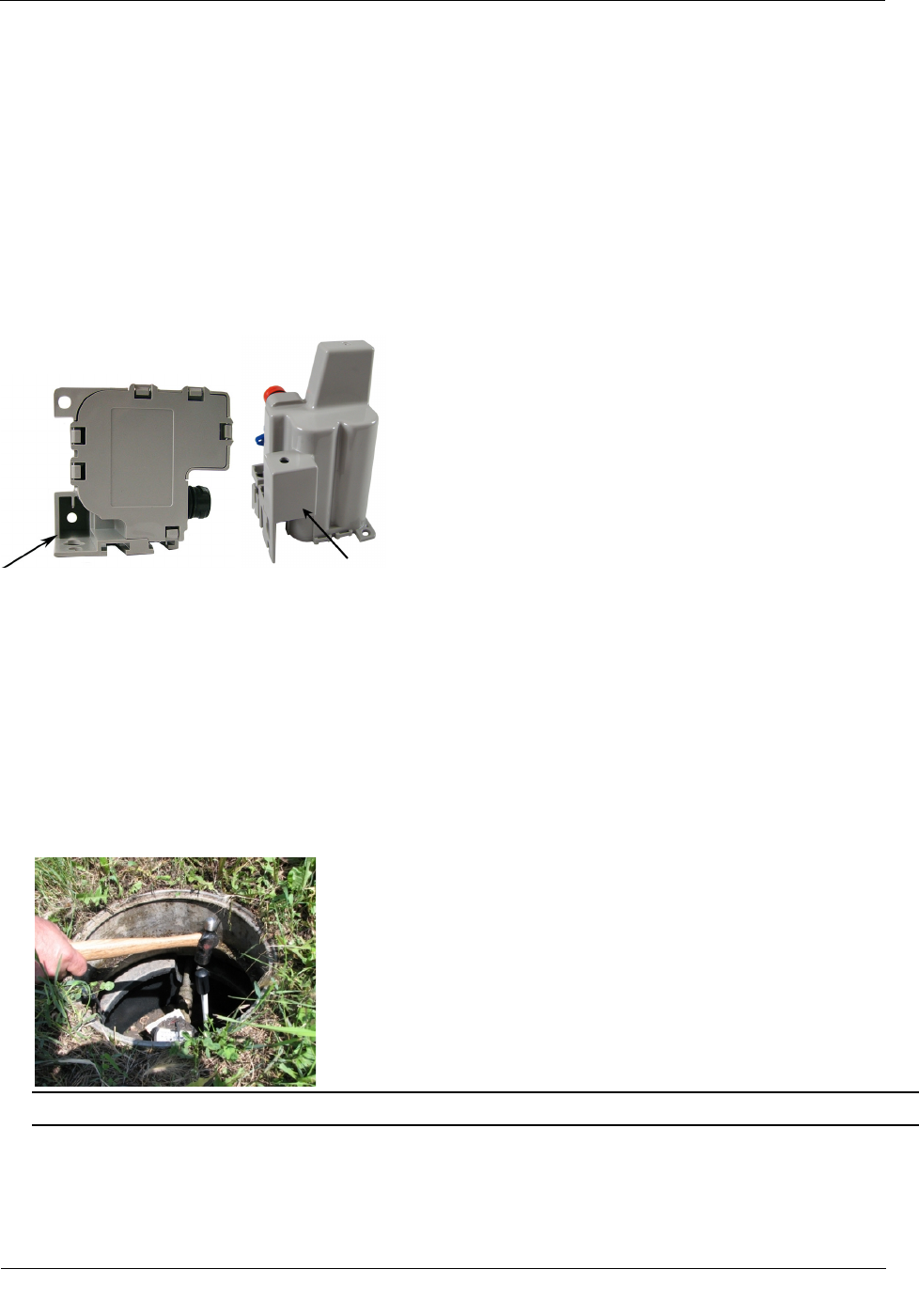
5. Drive the rod into the ground so the top of the rod is approximately 3-1/2 inches below the bottom of the
pit lid.
• If you cannot drive the rod in enough to equal the necessary spacing, cut the remaining rod length to
the proper height using an abrasive cut-off tool.
Caution Cutting fiberglass creates dust particles. Practice proper safety precautions when using cut-off
tools to prevent exposure to fiberglass dust particles.
• If the rod is the correct depth but remains loose in the soil, replace the rod with a longer version.
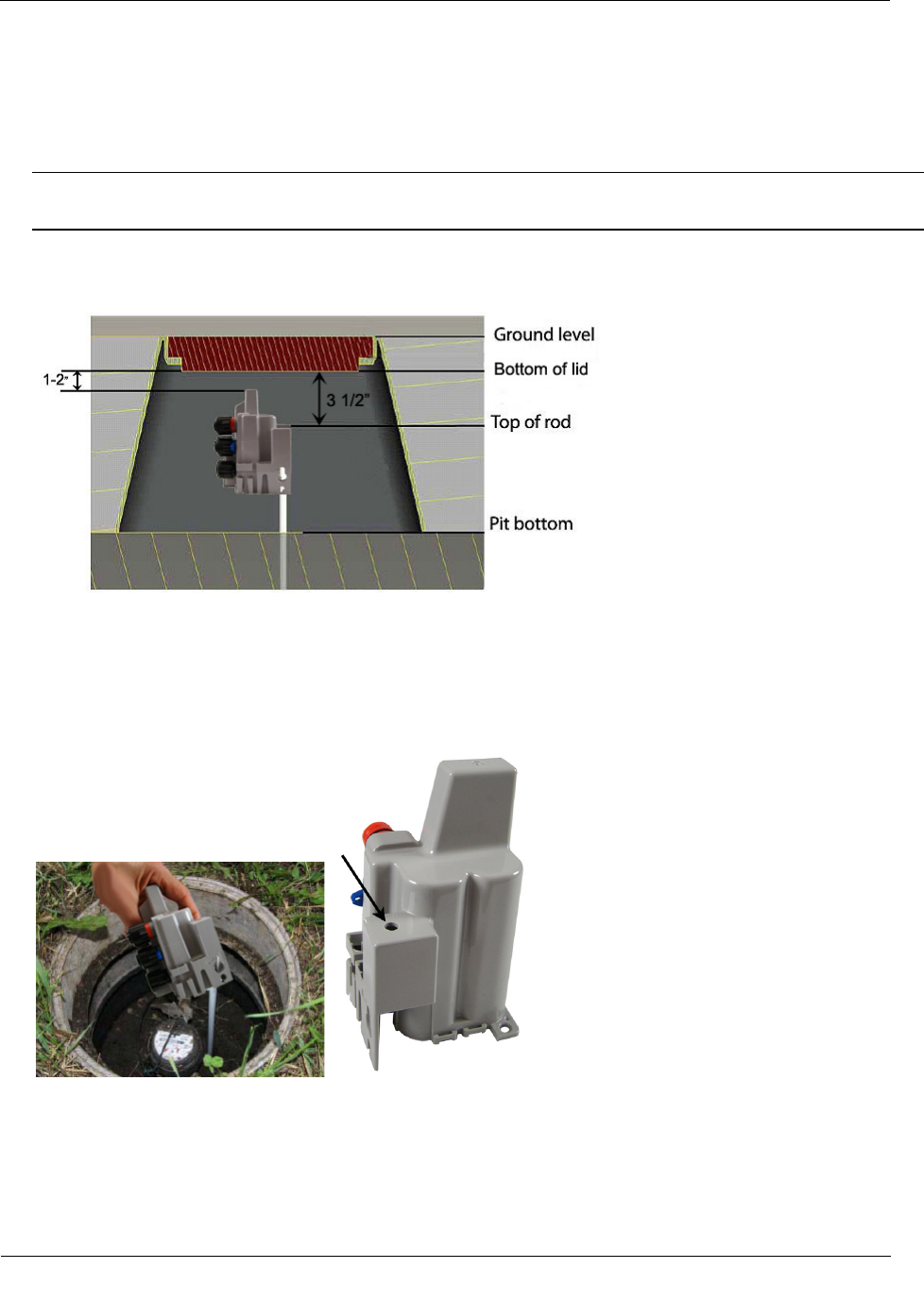
6. The top of the rod must be 3-1/2 inches below the bottom of the lid. Place the ERT module on the rod.
Completely insert the rod into the ERT module's rod mount hole. Do not force the ERT module onto the
rod. If the ERT module does not slide freely on the rod, remove the ERT module and examine the ERT
module rod hole and rod for burrs or obstructions. You may secure the ERT module to the rod with a self-
drilling screw through the hole in the top of the ERT module's rod mount cavity. The screw mounting hole
is shown in the following product image.
Installing the 100W/100W+ and 100WP/100WP+ ERT Module
TDC
-0909-006 100W/100W+ and 100WP/100WP+ Datalogging Water ERT Module Installation Guide 18
Proprietary and Confidential
7. Installation is complete when the ERT module is perpendicular to the underside of the lid. The ERT
module must not contact the pit structure or lid.
Caution Verify the pit lid does not touch the ERT module when the lid is replaced. There must be a 1 to
2-inch space between the top of the ERT module and the bottom of the pit lid. If the ERT module is
installed too high, too low, or is touching any of the surrounding surfaces, adjust as necessary.
Wall Mount Installation
Select a flat vertical mounting surface. Install the ERT module in an upright position. Locate the ERT module
as high as possible. To mount the ERT module to the wall in a water pit box, select a mounting location on the
inside of the pit box and try to maintain a distance of one to two inches from the bottom of the pit box lid.
Caution Observe the following guidelines for mounting the ERT module using the wall mount
procedure:
• ERT module positioning other than upright could negatively affect radio performance
and battery life.
• Do not use gel connectors in pit environments; use only Itron-approved splice kits or
inline connectors.
The ERT module works accurately with Itron-approved cable type and lengths up to 300 feet.
Required Mounting Tools and Hardware
• Drill and drill bits appropriate for mounting location material.
• Common hand tools for the selected fastening method.
• #10 size pan head mounting screws appropriate for the wall or pit box material.
Installing the 100W/100W+ and 100WP/100WP+ ERT Module
TDC
-0909-006 100W/100W+ and 100WP/100WP+ Datalogging Water ERT Module Installation Guide 19
Proprietary and Confidential
To install the 100W/100W+ and 100WP/100WP+ ERT module using the wall mount procedure
1. Select a vertical surface in the pit box or on a wall (for example, an ERT module mounted in a basement).
2. Position the ERT module vertically so the top of the ERT module is between 1 and 2-inches below the
bottom of the lid.
3. Mark the location of the top mounting hole.
4. Drill a pilot hole in the pit box wall. Follow the screw manufacturer's recommendation for the pilot hole
size.
5. For concrete-type pit boxes, it may be necessary to use a screw anchor. Choose an anchor appropriate for
a #10 pan head screw.
Caution Do not over-tighten the mounting screws. Over-tightening the mounting screws may break the
ERT module mounting tabs.
6. Start a screw into the pilot hole. Using the top hole of the ERT module, set the ERT module over the
screw head and slide it down so the screw is now at the top of the notch (as shown). Carefully tighten the
screw until snug. Over-tightening the mounting screw could crack the ERT module housing.
Note If mounting requires a screw anchor, mark the location of the bottom anchor and remove the ERT
module. Drill the required mounting hole, insert the anchor, and re-attach the ERT module.
7. Holding the ERT module in the upright position, drill the second pilot hole. Use the bottom mounting hole
as a template.
Caution Any ERT module position other than upright may negatively affect radio performance and
battery life.
8. Screw the bottom screw into the pilot hole until snug. Do not over-tighten the mounting screw.

Installing the 100W/100W+ and 100WP/100WP+ ERT Module
TDC
-0909-006 100W/100W+ and 100WP/100WP+ Datalogging Water ERT Module Installation Guide 20
Proprietary and Confidential
100W/100W+ and 100WP/100WP+ ERT Module Installation in a New Lid
This section describes installation of the 100W/100W+ and 100WP/100WP+ ERT module in a pit lid without
a drilled hole.
To install the 100W/100W+ and 100WP/100WP+ ERT Module in new lids
1. Select a hole location with enough clearance on the bottom side of the lid to attach the threaded clip collar.
2. Drill a 1-3/4 inch hole in the lid.
3. See To install in lids with holes using the Pit Lid Mounting Kit to complete installation in a new lid.
Base Mount Installation
The ERT module may be mounted to a flat surface using the base tab.
Caution Observe the following guidelines for mounting the ERT module using the wall mount
procedure:
• ERT module positioning other than upright could negatively affect radio performance
and battery life.
•
Use only Itron-approved splice kits or inline connectors.
Required Mounting Tools and Hardware
• Drill and drill bits appropriate for mounting location material.
• Common hand tools for the selected fastening method.
• #10 size pan head mounting screws appropriate for the wall or pit box material.
To install the 100W/100W+ and 100WP/100WP+ ERT module using the base mount procedure
1. Select a flat surface.
2. Position the ERT module vertically.
3. Mark the mounting-hole location.
4. Drill a pilot hole in the mounting location material. Follow the screw manufacturer's recommendation for
the pilot hole size.
5. Position the ERT module and insert a #10 pan head screw in the base mounting tab. Carefully tighten the
mounting screw until the ERT module is secure.
Installing the 100W/100W+ and 100WP/100WP+ ERT Module
TDC
-0909-006 100W/100W+ and 100WP/100WP+ Datalogging Water ERT Module Installation Guide 21
Proprietary and Confidential
Caution Do not over-tighten the mounting screws. Over-tightening the mounting screws may break the
ERT module mounting tabs.
Shelf Mount Installation
This section describes 100W/100W+ and 100WP/100WP+ ERT module installation using a shelf mount
adapter to mount the ERT module in a pit lid slot.
Caution Observe the following guidelines for mounting the ERT module using the shelf
mount procedure:
• ERT module positioning other than upright could negatively affect radio
performance and battery life.
• Use only Itron-approved splice kits or inline connectors.
The pit lid and slot must have the correct dimensions for the ERT module assembly to fit
properly.
Installing the 100W/100W+ and 100WP/100WP+ ERT Module
TDC
-0909-006 100W/100W+ and 100WP/100WP+ Datalogging Water ERT Module Installation Guide 22
Proprietary and Confidential
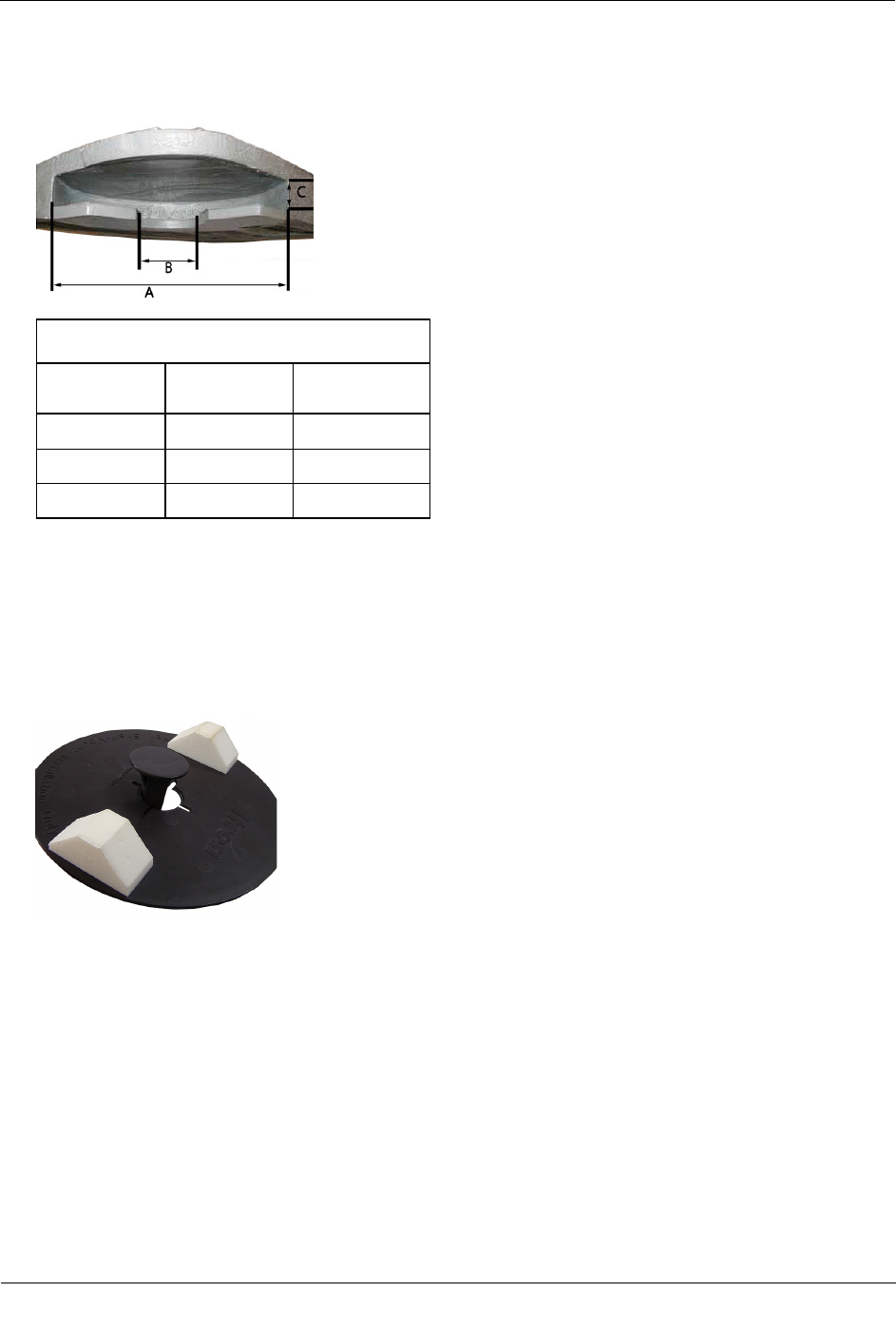
The following illustration and the accompanying table give pit lid slot dimensions for the shelf mount
installation method.
Pit Lid Slot Dimensions
Dimension Minimum
(inches)
Maximum
(inches)
A 6 3/4 N/A
B 2 5 3/4
C 3/4 1
Required Hardware
Itron 100W Series Shelf Mount Kit
To install using the shelf mount adapter
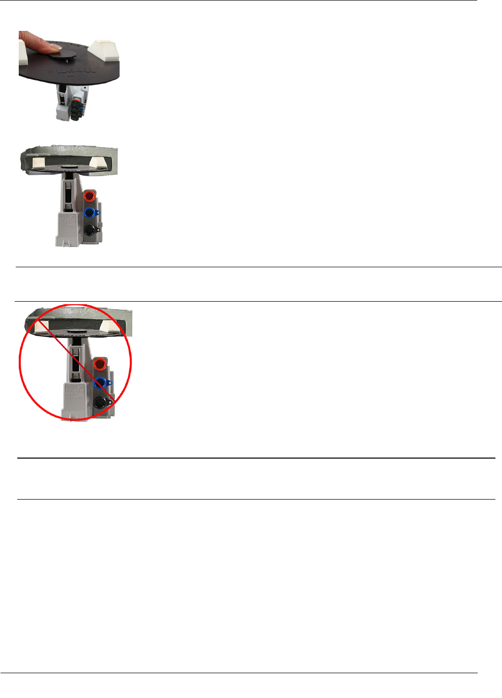
1. With the foam spacers facing up, insert the shelf mount adapter into the opening in the disk.
2. Push the adapter into the opening gently until the adapter snaps into place. Insert the shelf mount adapter
into the ERT module antenna slot pushing firmly with your thumb until the adapter tab locks into place in
the ERT module antenna slot opening.
Installing the 100W/100W+ and 100WP/100WP+ ERT Module
TDC
-0909-006 100W/100W+ and 100WP/100WP+ Datalogging Water ERT Module Installation Guide 23
Proprietary and Confidential
3. Slide the adapter assembly into the pit lid with the foam spacers positioned on each side of the pit lid slot.
Correct position for foam spacers
Caution Do not install the adapter assembly in a manner that provides little or no support under disk's
edge.
Incorrect mounting position for foam spacers.
4. The installed ERT module position must be vertical and upright when the lid is replaced on the pit.
Caution When placing the pit lid on to the pit box after the shelf mount adapter installation, use care to
avoid pinching or damaging the ERT module to meter cable. Any ERT module position other than upright
may negatively affect radio performance and battery life.
Through Lid Installation
This section provides instructions to mount the 100W/100W+ and 100WP/100WP+ ERT module in a pit lid
with a drilled, round 1-3/4-inch, 1-7/8-inch, or 2-inch hole.