Itron 100WD AMR transceiver device for utility meters User Manual Installation guide 3
Itron Inc AMR transceiver device for utility meters Installation guide 3
Itron >
Contents
Installation guide 3
Installing the 100W-R/100W-R+ and 100WP-R/100WP-R+ ERT Module
TDC
-0951-006 100W-R/100W-R+ and 100WP-R/100WP-R+ Datalogging ERT Module Installation Guide 26
Proprietary and Confidential
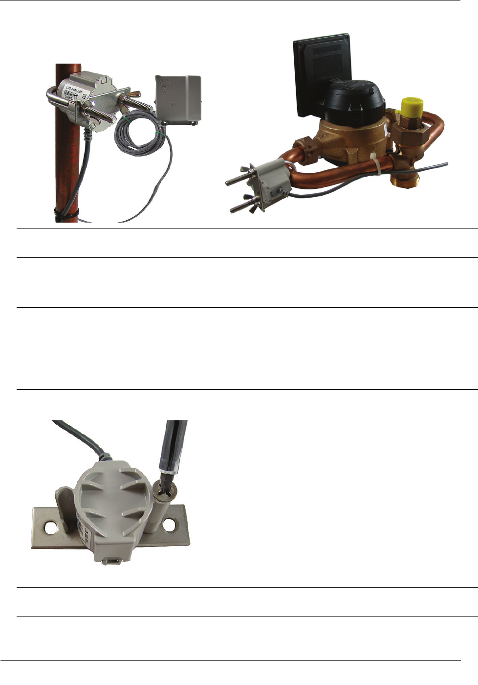
Note Leak Sensor mounting orientation is not critical. Orient the Sensor to best accommodate your
installation. The most important installation practice is to mount the Sensor securely to the pipe.
To install the Leak Sensor on a pipe (up to 2 1/2-inch OD)
1. Select a Leak Sensor mounting location within 5-feet of the 100W ERT module.
Note Leak Sensor mounting orientation is not critical. Orient the Sensor to best accommodate your
installation. The most important installation practice is to fasten the Sensor securely to the pipe.
Caution The Leak Sensor must be mounted on the water input side of the meter. Failure to follow this
mounting requirement could result in errors in the leak detection data. Installation requires Itron mounting
hardware. Repair costs and service charges relating to the use on non-compliant mounting hardware will
be charged to the customer. Contract Itron Support for more information.
2. Align the mounting plate screw holes with the holes on the 2-inch bolt mounting plate. Secure the
mounting plate to the Leak Sensor.
3. Select a Leak Sensor mounting location within 5-feet of the 100W ERT module.
Note Leak Sensor mounting orientation is not critical. Orient the Sensor to best accommodate your
installation. The most important installation practice is to fasten the Sensor securely to the pipe.
Installing the 100W-R/100W-R+ and 100WP-R/100WP-R+ ERT Module
TDC
-0951-006 100W-R/100W-R+ and 100WP-R/100WP-R+ Datalogging ERT Module Installation Guide 27
Proprietary and Confidential
Caution The Leak Sensor must be mounted on the water input side of the meter. Failure to follow this
mounting requirement could result in errors in the leak detection data. Installation requires Itron mounting
hardware. Repair costs and service charges relating to the use on non-compliant mounting hardware will
be charged to the customer. Contract Itron Support for more information.
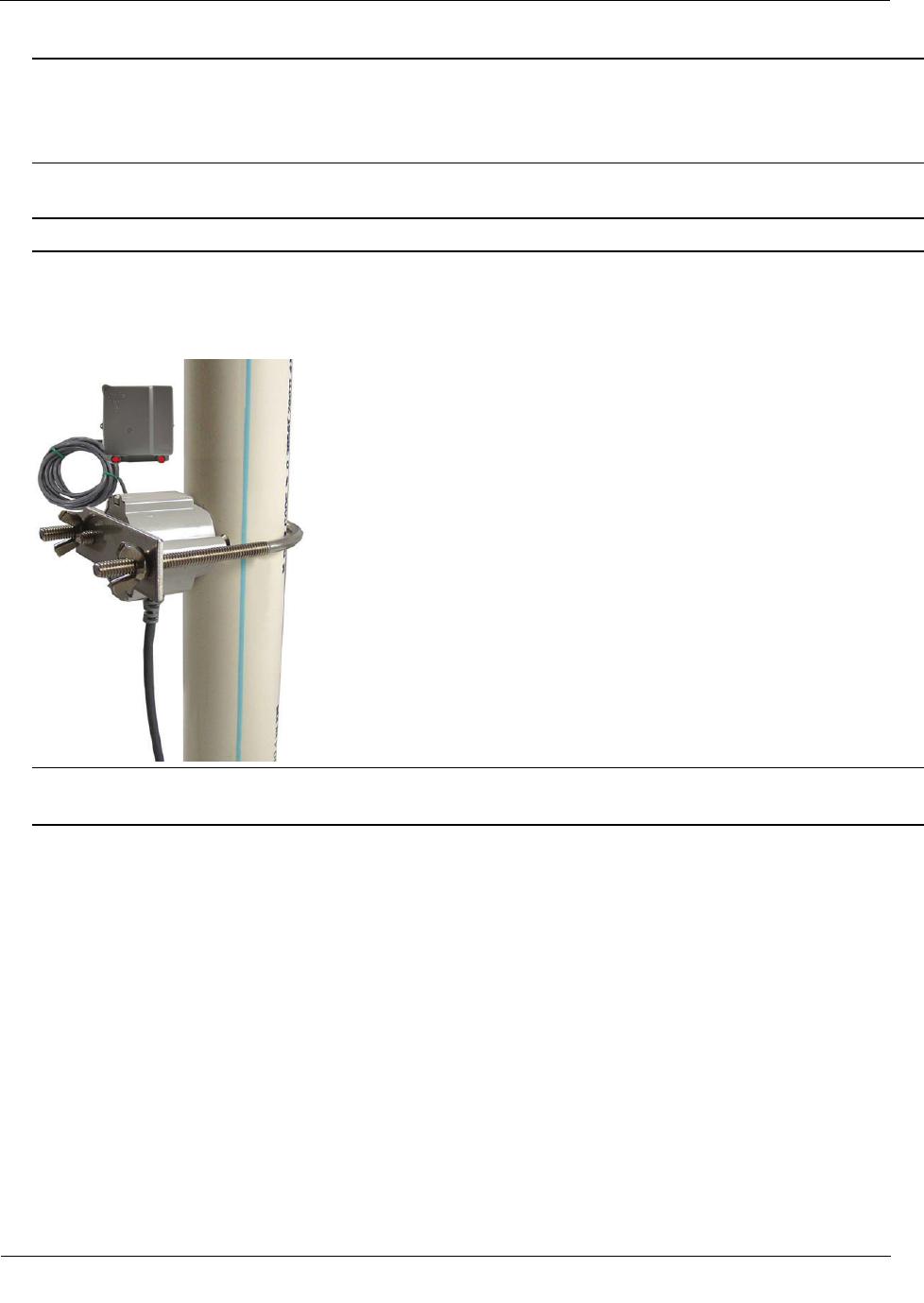
4. Verify the pipe’s mounting surface is free from dirt and debris. Place the curved surface of the LS against
the pipe.
Caution Do not mount the Leak Sensor on a pipe coupler, joint, or nut.
5. Insert the U-bolt around the pipe and into the holes in the plate/Leak Sensor assembly. Secure the U-bolt
with the wing nuts. Tighten the wing nuts until snug (to a minimum of 5-inch pounds) to prevent device
rotation on the pipe. After the second wing nut is tightened, check the Leak Sensor to verify the device is
snug. If the sensor moves, tighten the wing nuts until there is no movement.
Caution Do not tighten the Leak Sensor to more than 20 inch-pounds. Over-tightening could damage the
Leak Sensor housing and/or the pipe.
Remote Mount Installation
Connect the ERT module to the register as described in Initializing, Programming, and Connecting the ERT
Module.
Using a back plate, create a template by drilling through a back plate lug slot to mark the position of the
screw. Use the drilled back plate as your mounting template.
The arrow on the ERT module must point up when installation is complete.
Installing the 100W-R/100W-R+ and 100WP-R/100WP-R+ ERT Module
TDC
-0951-006 100W-R/100W-R+ and 100WP-R/100WP-R+ Datalogging ERT Module Installation Guide 28
Proprietary and Confidential
Required Equipment
Equipment
Itron Part Number
Description
Leak Detection Sensor LDS-0001-001 LDS with bracket; 5-foot cable, and mounting bolt (fits up to 1-1/2-
inch OD pipe).
Optional mounting bracket CFG-0349-002 Mounting bolt fits up to 2-1/2-inch OD pipe.
100W-R Encoder Remote ERW-1300-214 100W-R with Leak Sensor, 10-inch flying lead.
100W-R+ Encoder Remote ERW-1300-314 100W-R+ with Leak Sensor, 10-inch flying lead.
100WP-R Pulser Remote ERW-1300-216 100WP-R with Leak Sensor, 10-inch flying lead.
100WP-R+ Pulser Remote ERW-1300-316 100WP-R+ with Leak Sensor, 10-inch flying lead.
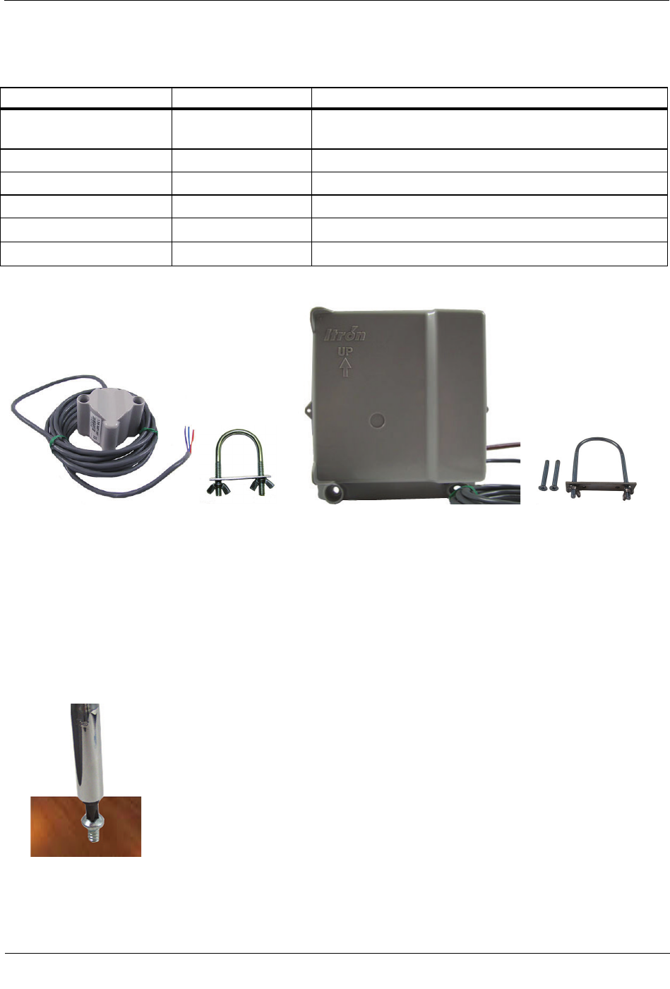
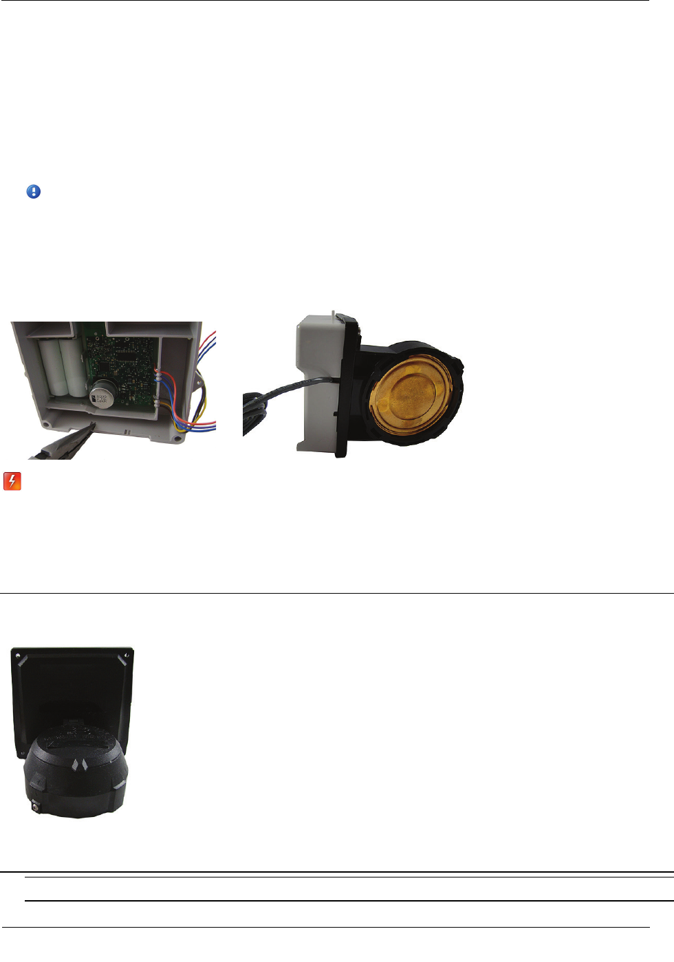
Leak Sensor Standard mounting 100W remote ERT module Optional mounting
bracket bracket
To install the remote ERT module on a flat surface
1. Select an installation location.
2. Using a back plate template, drill three pilot holes into the wall or other surface. The two bottom holes
should be level.
3. Screw a mounting screw for the lug slot into the surface, leaving approximately 1/8-inch of the screw
protruding. The lug slot should slide over the screw with a tight fit.
Installing the 100W-R/100W-R+ and 100WP-R/100WP-R+ ERT Module
TDC
-0951-006 100W-R/100W-R+ and 100WP-R/100WP-R+ Datalogging ERT Module Installation Guide 29
Proprietary and Confidential
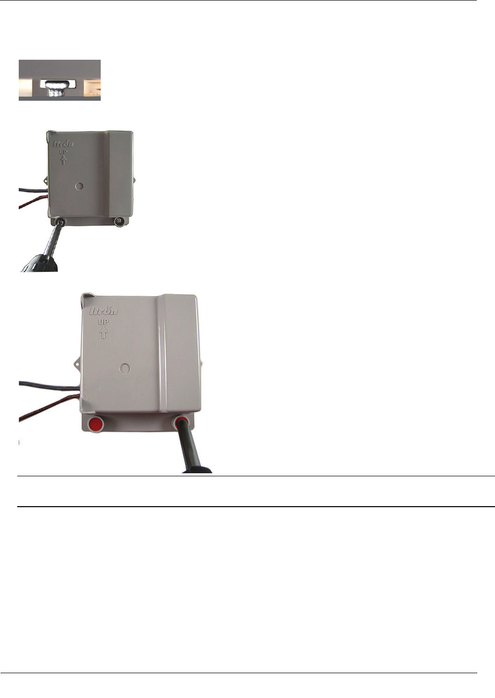
4. Slide the ERT lug slot onto the mounting screw, pushing the ERT module upward until the screw head is
all the way into the slot.
5. Screw the ERT module to the wall using the remaining two mounting screws.
6. Insert a tamper seal over each mounting screw and drive into place with a nut driver or a similar tool.
Note A tamper seal is fully seated when the top of the tamper seal is approximately 1/16 inch below the
top of the screw recess.
7. Secure any excess cable using the provided cable ties.
Installing the 100W-R/100W-R+ and 100WP-R/100WP-R+ ERT Module
TDC
-0951-006 100W-R/100W-R+ and 100WP-R/100WP-R+ Datalogging ERT Module Installation Guide 30
Proprietary and Confidential
Direct-Mounting to the Meter Register
Direct mounting ERT modules to a meter register requires a register designed for that purpose. This section
describes 100W-R/100W-R+ and 100WP-R/100WP-R+ installation for the following direct mount registers:
• Badger ADE and RTR
• Elster/AMCO (ABB) Scancoder, InVISION, and Digital
Note If you are installing an ERT module with Leak Sensor capability, use a needle-nose pliers to
remove one of the ERT module's housing knock-outs to accommodate the Leak Sensor cable. If
your meter register has a raised internal rim, remove the larger case knock-out. When you are
installing a Leak Sensor with the 100W-R or 100WP-
R, you must install cable strain relief prior to
installing the ERT module. For more information, see Installing the 100W-R/100W-R+ and
100WP-R/100WP-R+ ERT Module Cable Strain Relief.
Warning Do not use the direct mounting method in a pit environment. Use a pit ERT
module for pit environments. 100W-R/100W-R+ and 100WP-R/100WP-R+ ERT modules
direct mounted in a pit environment are not covered by the Itron warranty.
To install the 100W-R/100W-R+ and 100WP-R/100WP-R+ ERT Module to a Badger Direct-
Mount register
Caution
Verify you have a Badger meter with a register designed for direct mount ERT modules.
Check the part number on the label to verify the module matches the meter.
Always install the module with the arrow on the housing pointing upward.
Note The register may or may not be mounted on the meter when performing the following steps.
Installing the 100W-R/100W-R+ and 100WP-R/100WP-R+ ERT Module
TDC
-0951-006 100W-R/100W-R+ and 100WP-R/100WP-R+ Datalogging ERT Module Installation Guide 31
Proprietary and Confidential
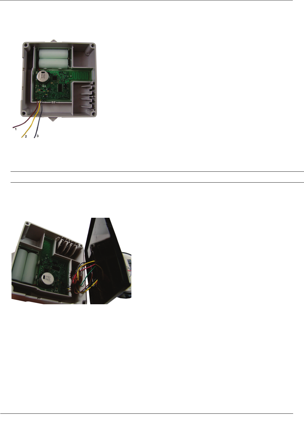
1. Direct-meter mounting requires a 100W-R/100W-R+ ERT module for the Badger ADE register or a
100WP-R/100WP-R+ for the RTR register. Both ERTs have three wires:
(1) brown insulated wire
(2) yellow insulated wire
(3) gray insulated wire
Note For an RTR register, tuck the unused yellow wire into the housing.
2. Connect the ERT module wires to the register using gel-cap connectors (see Using Gel cap Connectors)
following the 100W-R/100W-R+ encoder to the Badger ADE register wire connections, (see Connecting
100W-R/100W-R+ to a Remote Meter Register). After connecting the wires, carefully tuck the connectors
into the ERT module housing.
3. To wire the 100WP-R/100WP-R+ to the RTR 2-wire register, connect the ERT module wires to the 2-
wire register using gel-cap connectors (see Using Gel cap Connectors). After connecting the wires,
carefully tuck the connectors into the ERT module housing.
Installing the 100W-R/100W-R+ and 100WP-R/100WP-R+ ERT Module
TDC
-0951-006 100W-R/100W-R+ and 100WP-R/100WP-R+ Datalogging ERT Module Installation Guide 32
Proprietary and Confidential
4. To connect the 100WP-R pulser to the RTR 2-wire register, see Connecting the 100WP-R/100WP-R+ to a
Remote Meter Register. The ERT module's yellow wire is not used. Tuck the yellow wire back into the
ERT module housing with the gel-cap connectors.
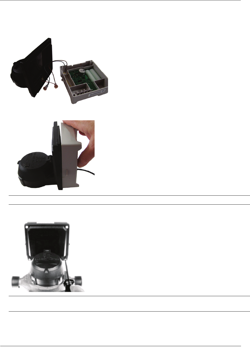
5. Place the ERT module on the register, ensuring the edge of the ERT module housing is seated properly
around the perimeter of the register as shown below.
Note A gasket is not required.
6. Install four Torx-head mounting screws (SCR-0010-005) as shown below and hand-tighten the screws.
Warning User Itron mounting screws (SCR-0010-005). Using the wrong mounting screws could crack
the plastic ERT module housing.
Installing the 100W-R/100W-R+ and 100WP-R/100WP-R+ ERT Module
TDC
-0951-006 100W-R/100W-R+ and 100WP-R/100WP-R+ Datalogging ERT Module Installation Guide 33
Proprietary and Confidential
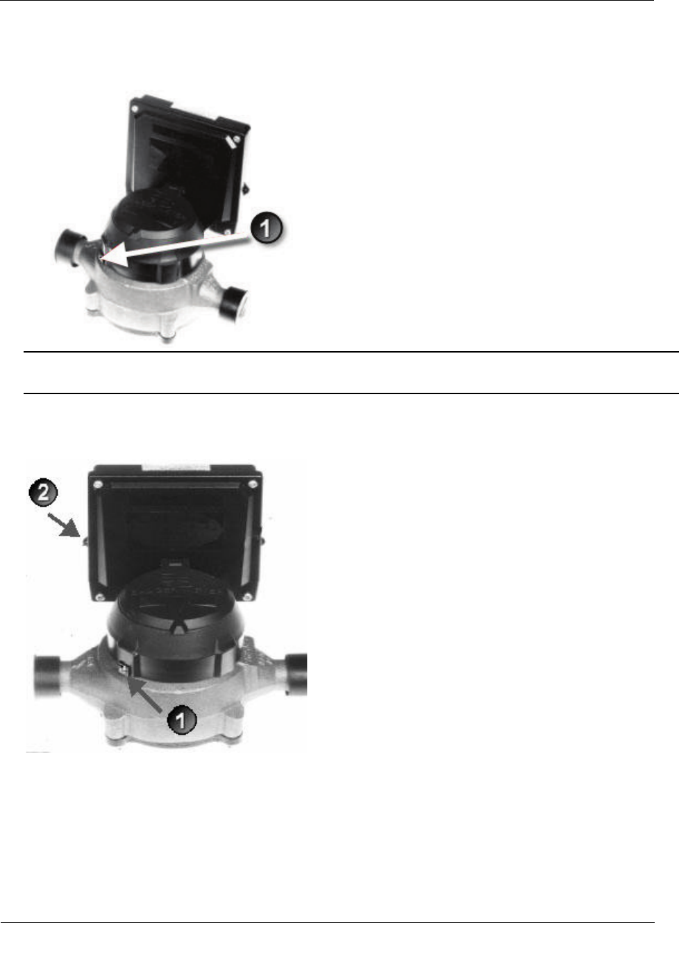
7. If you have not already done so, connect the register to the water meter and fully tighten the mounting
screw (1) as directed by Badger Meter.
Note Mount the register on the meter in one of four different positions with respect to the direction of
water flow (refer to the manufacturer's installation directions).
8. If the standard Torx screw is used (1), a wire seal is not necessary.
If the optional slotted and drilled RTR screw is used, install a wire seal through the drilled screw from (1)
to (2), or as specified by utility policy.
Installing the 100W-R/100W-R+ and 100WP-R/100WP-R+ ERT Module
TDC
-0951-006 100W-R/100W-R+ and 100WP-R/100WP-R+ Datalogging ERT Module Installation Guide 34
Proprietary and Confidential
To install the Elster/AMCO (ABB) Scancoder, InVISION, or Digital Direct-Mount
Caution
Verify you have an Elster/AMCO meter with a register designed for direct mount ERT modules.
Always install the ERT module right side up with the arrow on the housing pointed upward.
Note The register may or may not be mounted on the meter when performing the following steps.
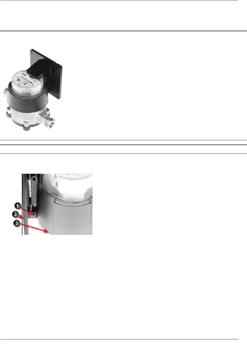
1. Push the hollow pin (1) completely out of its location and separate the ERT module mounting bracket (2)
from the meter register collar (3).