Itron 100WD AMR Transceiver device for utility meters User Manual P2
Itron Inc AMR Transceiver device for utility meters Users Manual P2
Itron >
Contents
Users Manual P2
Installing the 100W/100W+ and 100WP/100WP+ ERT Module
TDC
-0909-006 100W/100W+ and 100WP/100WP+ Datalogging Water ERT Module Installation Guide 24
Proprietary and Confidential
Through Lid Mount Required Tools and Hardware
This mounting method requires the Pit Lid Mounting Kit. Refer to the 100W Installation Methods Overview
(PUB-1300-004) for guidance on which kit to install for different pit lid material and traffic conditions.
Pit Lid Mounting Kit (CFG-1300-004)
Note The Pit Lid Mounting Kit is not intended for applications involving
vehicular traffic. Use the Remote Antenna Kit in incidental traffic areas (such as
residential environments).
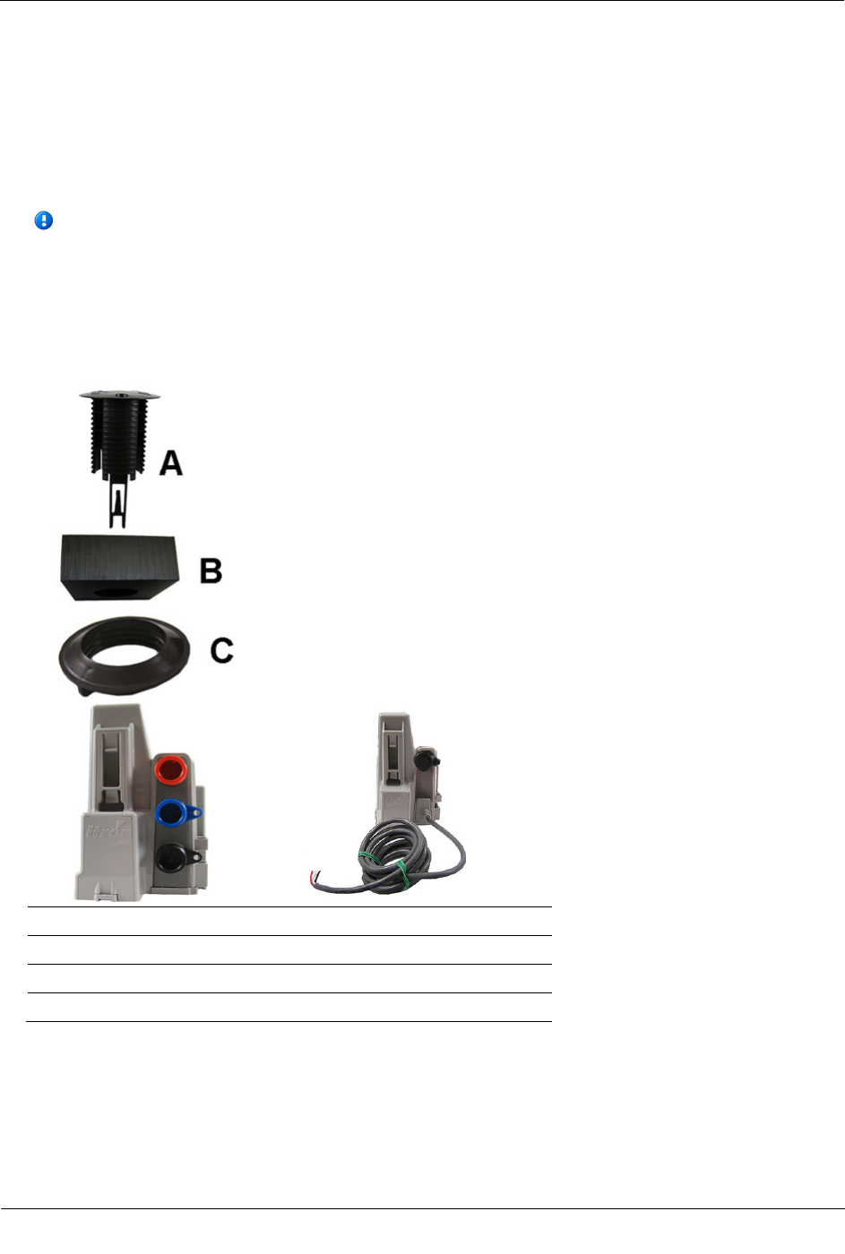
This section provides the instructions to install the 100W/100W+ and 100WP/100WP+ ERT module in a pit
lid with a hole using the Pit Lid Mounting Kit (CFG-1300-004). Verify you have the following items to
complete the installation.
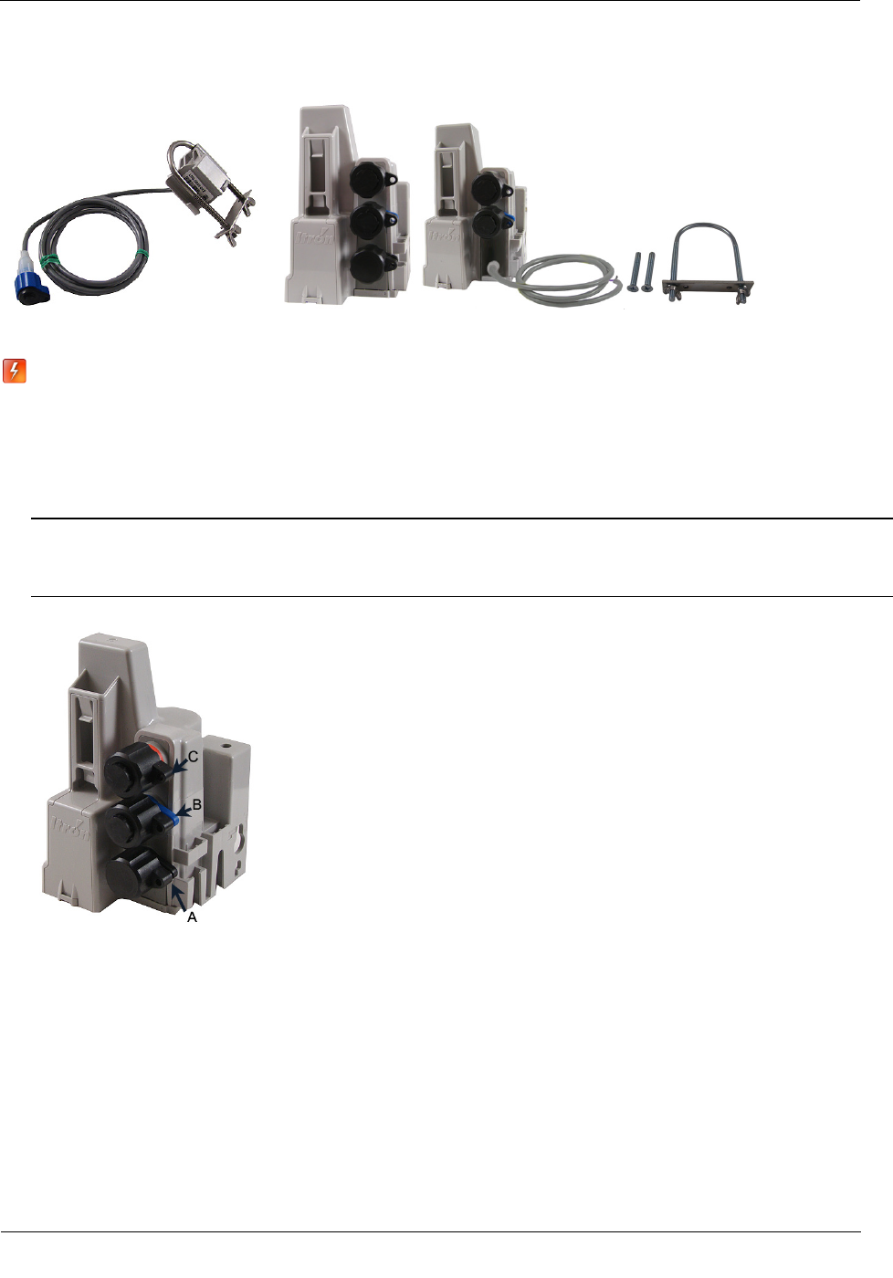
A Retainer clip
B Pit lid with a pre-drilled hole (simulated pit lid material shown)
C Retainer clip collar
D 100W/100W+ and 100WP/100WP+ ERT module
Installing the 100W/100W+ and 100WP/100WP+ ERT Module
TDC
-0909-006 100W/100W+ and 100WP/100WP+ Datalogging Water ERT Module Installation Guide 25
Proprietary and Confidential
To install in lids with holes using the Pit Lid Mounting Kit (CFG-0771-011)
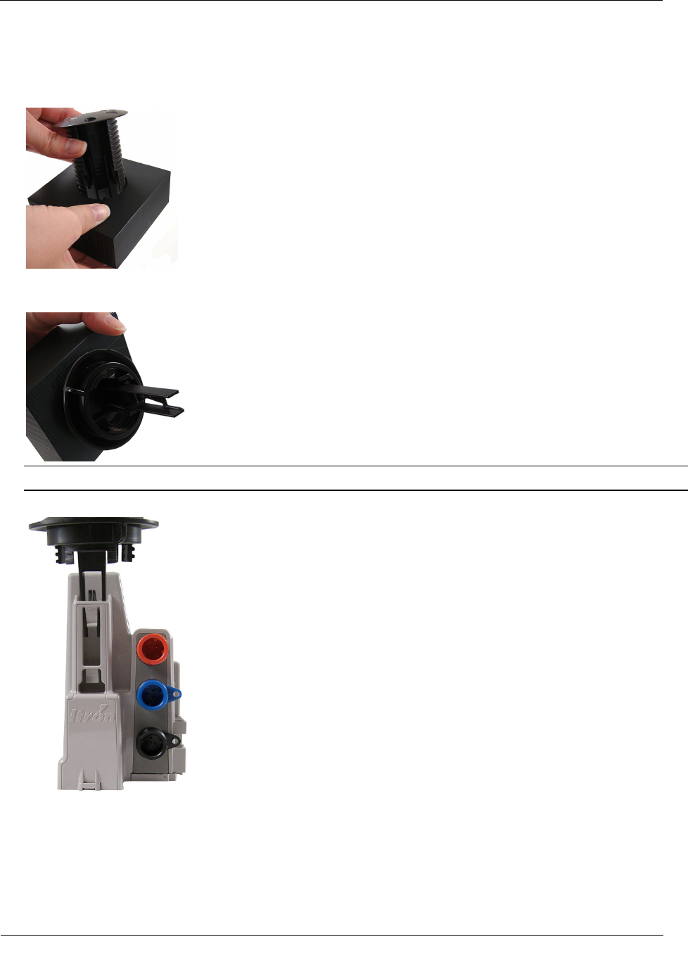
1. Insert the retainer clip into the pit lid hole with the convex surface on the top of the pit lid.
2. From the bottom side of the lid, screw on the threaded retainer clip collar until the beveled top rests
against the pit lid.
Note Ensure the beveled edge of the clip collar is toward the top of the pit lid.
3. Align and insert the retainer clip tab into the retainer clip receptacle on the ERT module housing.
Installing the 100W/100W+ and 100WP/100WP+ ERT Module
TDC
-0909-006 100W/100W+ and 100WP/100WP+ Datalogging Water ERT Module Installation Guide 26
Proprietary and Confidential
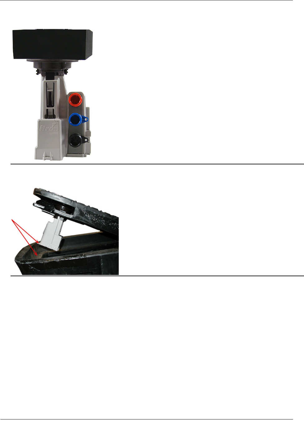
4. Verify the clip locks into place in the housing.
Caution Carefully align the ERT module through lid assembly. If the assembly is improperly aligned, the
pit lid may not close.
Pit lid mounting installation is complete.
Installing the 100W/100W+ and 100WP/100WP+ ERT Module
TDC
-0909-006 100W/100W+ and 100WP/100WP+ Datalogging Water ERT Module Installation Guide 27
Proprietary and Confidential
Optional Leak Sensor Installation
This section describes installation of the Leak Sensor (LS) in a 100W/100W+ and 100WP/100WP+ ERT
module system.
The ERT module stores 20 days of LS data. On the 21st day, the ERT module begins to write over stored data
in a first in, first out manner.
The ERT module automatically detects the presence of connected LS devices. The ERT module will
automatically detect the LS within 22.5 minutes and begin reading LS data. To immediately detect the LS and
begin reading data, perform a Check ERT with a handheld computer running FDM software.
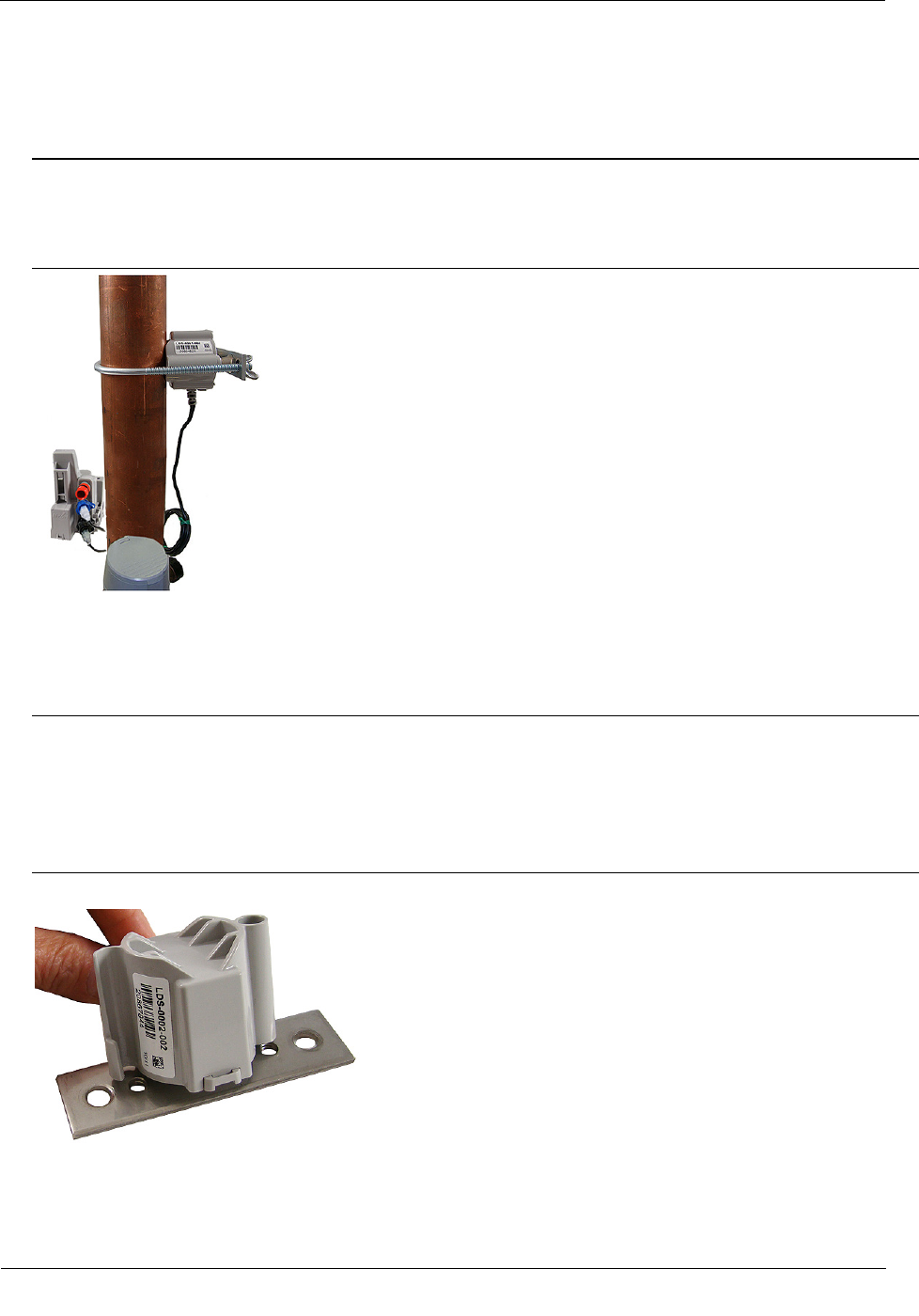
The LS is used in conjunction with both indoor (basement) and outdoor (mounting on the exterior of the
house) 100W/100W+ and 100WP/100WP+ ERT module installations. LS devices are mounted on a water
service pipe or meter insetter (meter horn) and connect to the LS connector on the ERT module as described
in To connect the Leak Sensor to the 100W/100W+ and 100WP/100WP+ ERT module on page 28. The
mounting bracket shipped with the LS accommodates an (up to) 1-1/2-inch OD pipe. An optional mounting
bracket is available for pipe sizes (up to 2 1/2-inch OD).
Leak Sensor Installation Equipment
Equipment
Itron Part Number
Description
Leak Sensor LDS-0001-002
LS with inline connector, environmental connector cap; 5-foot cable, and
mounting bolt (fits up to 1 1/2-inch OD pipe).
Optional mounting bracket CFG-0349-002 Mounting bolt fits up to 2 1/2-inch OD pipe.
ERT module
100W three-port ERT module ERW-1300-203 Triple port encoder ERT module for connection to register, Leak Sensor
or remote SO, and optional remote antenna.
100W, 5-ft. flying leads, two-port
ERT module
ERW-1300-206 Three-port encoder ERT module for connection to register using 5-ft.
flying leads, Leak Sensor or remote SO and optional remote antenna
connection with inline connectors.
100W, 20-in. flying leads, three-
port encoder ERT module
ERW-1300-218 Three-port encoder ERT module for connection to register using 20-in.
flying leads, Leak Sensor or remote SO, and optional remote antenna
connection with inline connectors.
100WP Three-port ERT module ERW-1300-209 Three-port pulser ERT module for connection to register, Leak Sensor or
remote SO, and optional remote antenna.
100WP, 5-ft. flying leads, two-
port ERT module
ERW-1300-212 Three-port pulser ERT module for connection to register using 5-ft.
flying leads, Leak Sensor or remote SO, and optional remote antenna
connection with inline connectors.
100WP, 20-in. flying leads, three-
port pulser ERT module
ERW-1300-220 Three-port pulser ERT module for connection to register using 20-in.
flying leads, Leak Sensor or Remote SO, and optional remote antenna
connection with inline connectors.
25-foot extension cable (optional) CFG-0349-101 25-foot cable with coordinating connectors (LS or SO blue connector,
register black connector).
100W LS environmental
replacement cap
MSC-0019-008
Protects Leak Sensor or remote SO connector when the LS or remote SO
is not connected to the 100W ERT module.
Itron Security Seal MSC-0018-001 Indicates module tampering and ensures the protective cover stays intact.
Installing the 100W/100W+ and 100WP/100WP+ ERT Module
TDC
-0909-006 100W/100W+ and 100WP/100WP+ Datalogging Water ERT Module Installation Guide 28
Proprietary and Confidential
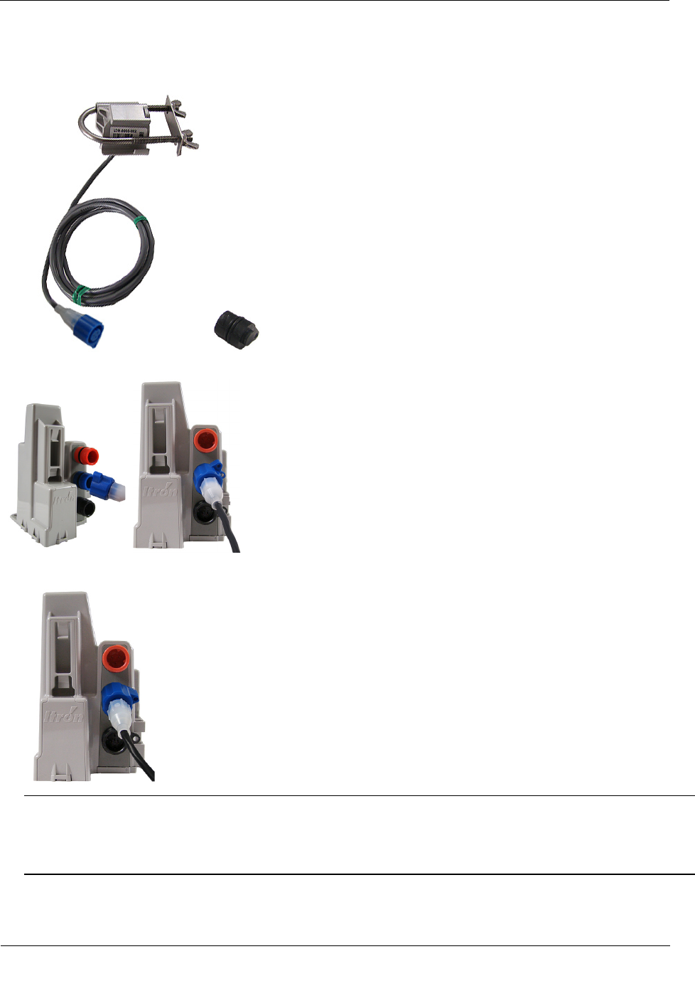
Warning When the 100W/100W+ or 100WP/100WP+ is installed but the LS is not attached,
you must protect the blue port with the universal environmental cap (MSC-0019-008). If you
remove the LS from the ERT module, the environmental cap must be replaced to protect the
connector.
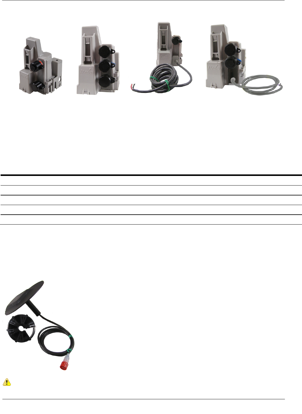
To connect the Leak Sensor to the 100W/100W+ and 100WP/100WP+ ERT module
Caution Verify you have the correct 100W/100W+ or 100WP/100WP+ ERT module. Leak Sensors must
mount to Port B (middle blue port) of the ERT module. Connecting the LS to Port A (bottom port) or Port
C (top port) will cause electrical damage to the LS and ERT module.
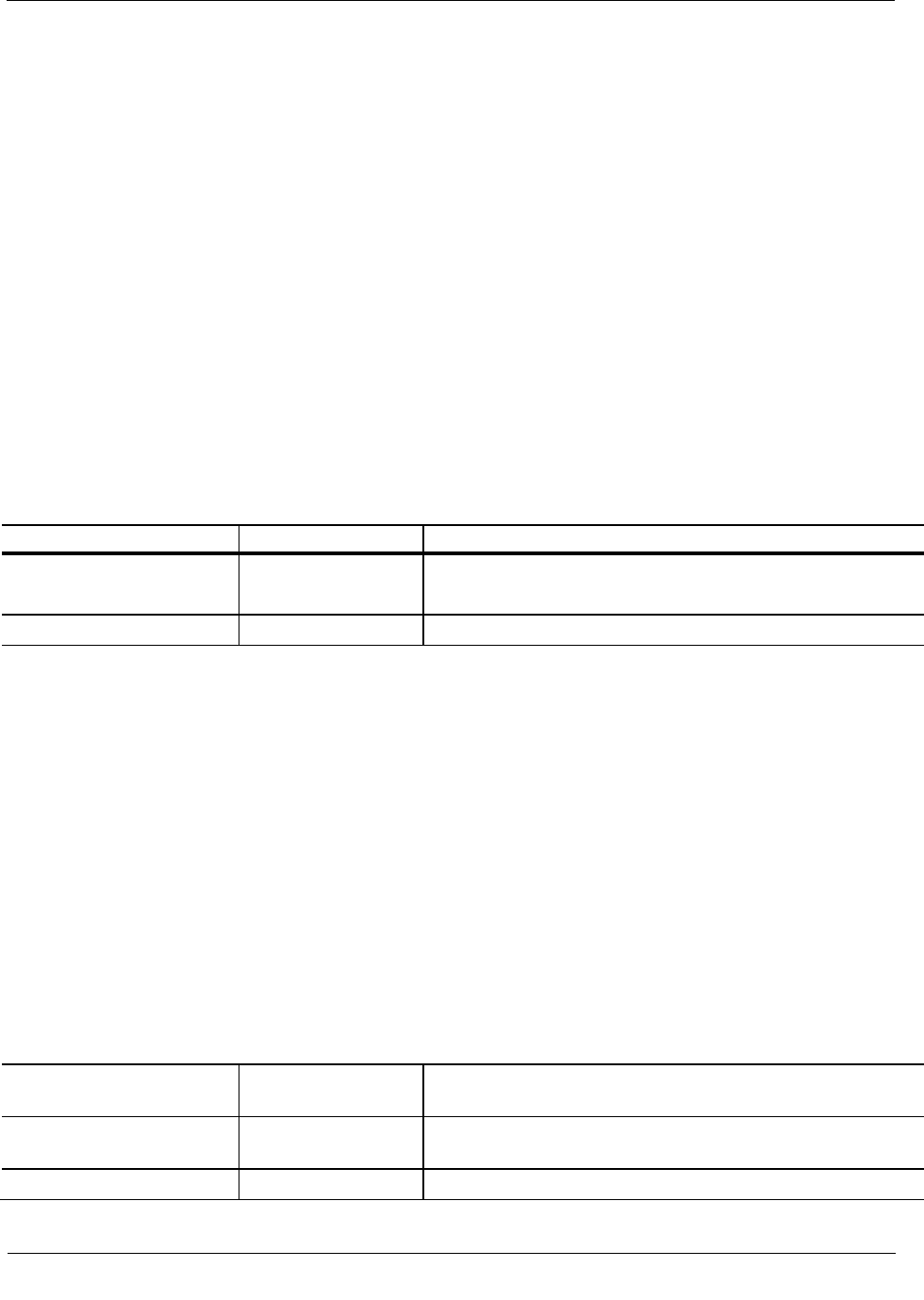
1. Remove the environmental cap from the ERT module's blue connector (B).
C. Red connector: Optional antenna connection
B. Blue connector: Leak Sensor connection
A. Black connector: register connection
Installing the 100W/100W+ and 100WP/100WP+ ERT Module
TDC
-0909-006 100W/100W+ and 100WP/100WP+ Datalogging Water ERT Module Installation Guide 29
Proprietary and Confidential
2. Remove the environmental cap from the Leak Sensor connector. Verify the connectors (the ERT module's
LS connector and the Leak Sensor connector) are clean and dry.
3. Align the Leak Sensor connector with the ERT module's blue connector and insert.
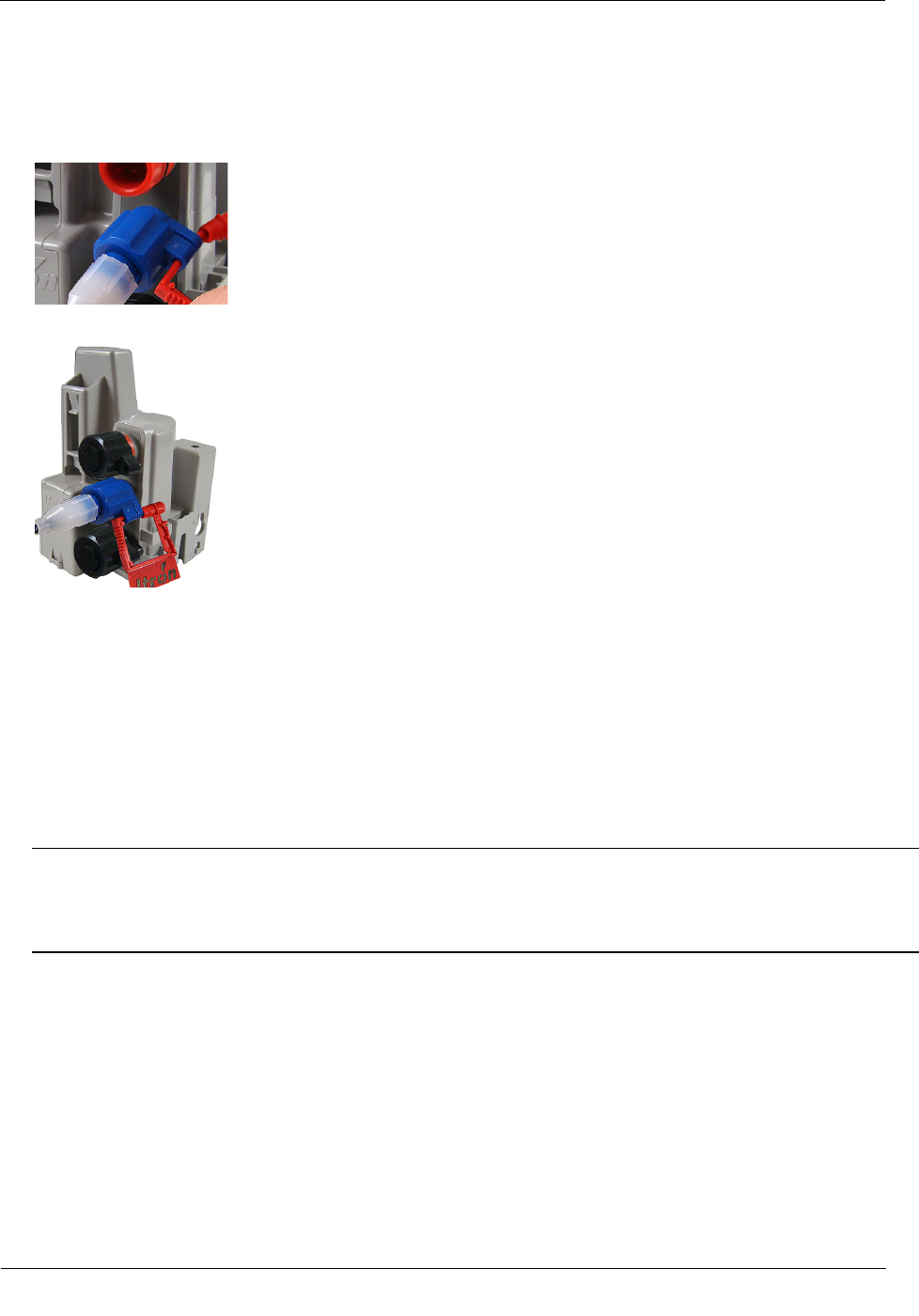
4. Rotate the connector locking ring until the security holes align.
Caution Do not force the connector ends together. While you hold the LS connector, engage the ERT
module's connector by rotating the locking ring until both connectors securely connect. Twist only the
connector locking ring, not the body of the connector. Twisting the connector body could damage the
connector's pins.
Installing the 100W/100W+ and 100WP/100WP+ ERT Module
TDC
-0909-006 100W/100W+ and 100WP/100WP+ Datalogging Water ERT Module Installation Guide 30
Proprietary and Confidential
To attach an Itron Security Seal through the connector security hole
1. Insert the pointed end of the security seal through the inline connector and the ERT module connector
security holes.
2. Insert the pointed end of the security seal into the capped end and push until the seal locks.
This completes the ERT module and Leak Sensor connections.
Pipe Preparation
Clean any dust or dirt from the pipe to facilitate direct contact with the LS surface.
To install the Leak Sensor on a pipe or meter insetter
1. Select a Leak Sensor mounting location within 5-feet of the ERT module. Mount the sensor on the water
input side of the meter.
Caution Mount the Leak Sensor on the water input side of the meter. Failure to follow this mounting
requirement could result in errors in the leak detection data. Installation requires Itron mounting hardware.
Repair costs and service charges relating to the use on non-compliant mounting hardware will be charged
to the customer. Contract Itron Support for more information.
Installing the 100W/100W+ and 100WP/100WP+ ERT Module
TDC
-0909-006 100W/100W+ and 100WP/100WP+ Datalogging Water ERT Module Installation Guide 31
Proprietary and Confidential
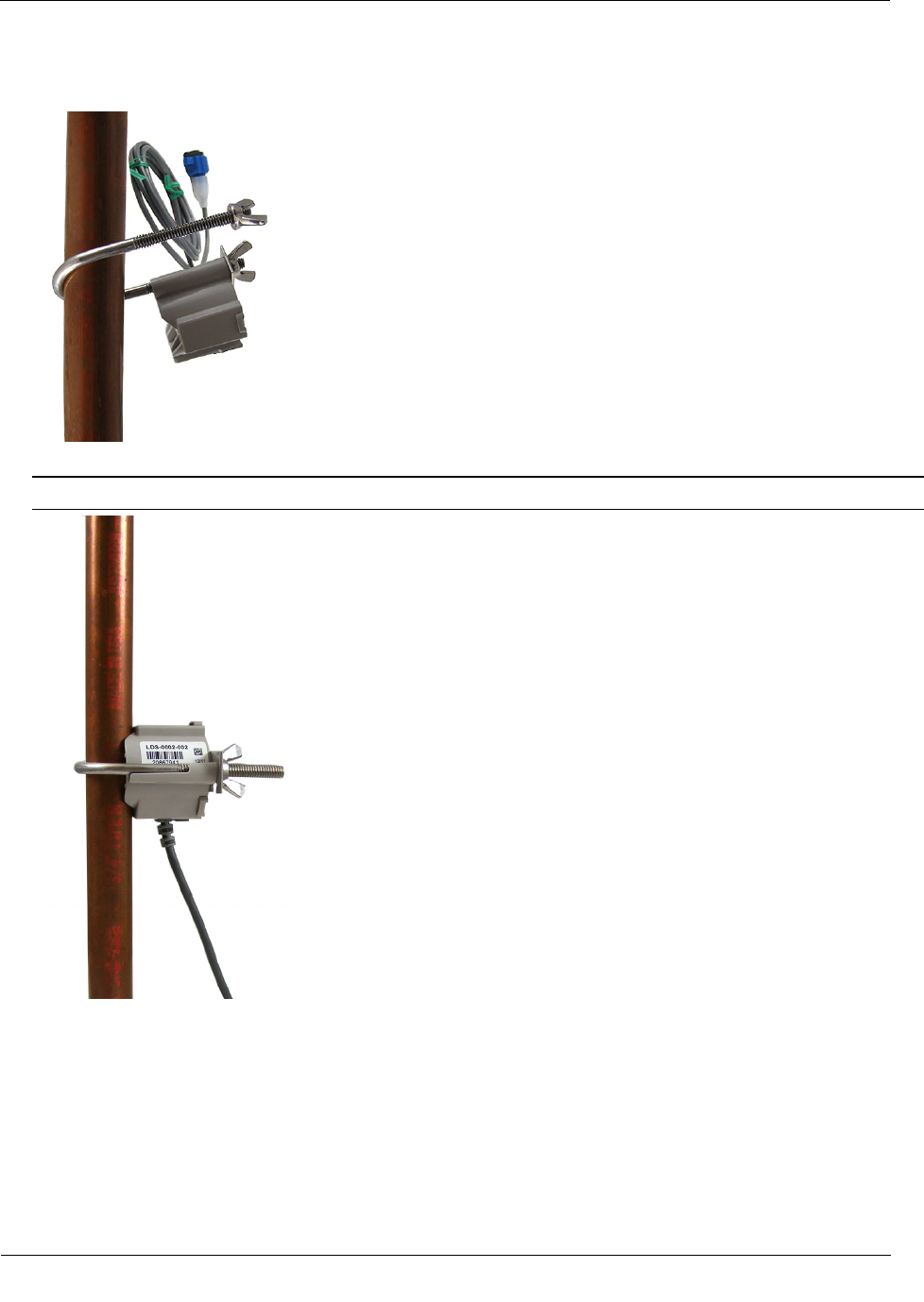
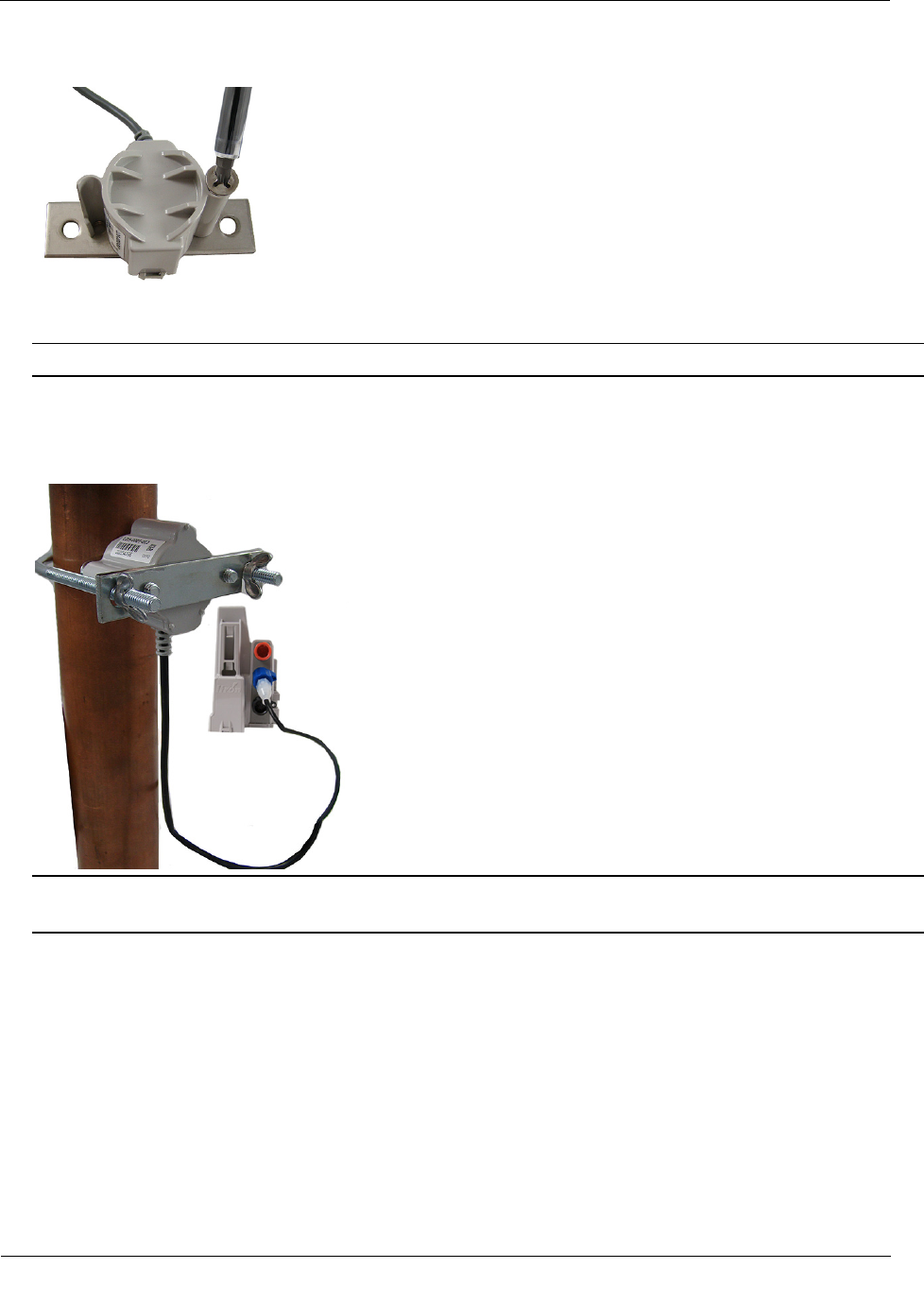
2. Verify the pipe’s mounting surface is free from dirt and debris. Place the curved surface of the LS against
the pipe.
3. Insert the mounting U-bolt over the pipe and into the LS mounting holes.
Caution Do not mount the Leak Sensor on a pipe coupler, joint, or nut.
Installing the 100W/100W+ and 100WP/100WP+ ERT Module
TDC
-0909-006 100W/100W+ and 100WP/100WP+ Datalogging Water ERT Module Installation Guide 32
Proprietary and Confidential
4. Insert the mounting plate over the U-bolt's threaded screw ends. Attach the two wing nuts over the clamp
screw ends and tighten the wing nuts until snug (to a minimum of 5-inch pounds) to prevent device
rotation on the pipe. After you tighten the second wing nut, check the Leak Sensor to verify the device is
snug. If the sensor moves, tighten the wing nuts until there is no movement.
Caution Do not tighten the Leak Sensor to more than 20 inch-pounds. Over-tightening could damage the
Leak Sensor housing and/or the pipe.
Note Leak Sensor mounting orientation is not critical. Orient the sensor to best accommodate your
installation. The most important installation practice is to mount the sensor securely to the pipe.
To install the Leak Sensor on a pipe (up to 2 1/2-inch OD)
1. Select a Leak Sensor mounting location within 5 feet of the ERT module.
Note Leak Sensor mounting orientation is not critical. Orient the sensor to best accommodate your
installation. The most important installation practice is to fasten the sensor securely to the pipe.
Caution Mount the Leak Sensor on the water input side of the meter. Failure to follow this mounting
requirement could result in errors in the leak detection data. Installation requires Itron mounting hardware.
Repair costs and service charges relating to the use on non-compliant mounting hardware will be charged
to the customer. Contract Itron Support for more information.
2. Insert the mounting plate screws into the holes on the Leak Sensor's curved surface.
Installing the 100W/100W+ and 100WP/100WP+ ERT Module
TDC
-0909-006 100W/100W+ and 100WP/100WP+ Datalogging Water ERT Module Installation Guide 33
Proprietary and Confidential
3. Secure the mounting plate to the Leak Sensor.
4. Verify the pipe’s mounting surface is free from dirt and debris. Place the curved surface of the LS against
the pipe.
Caution Do not mount the Leak Sensor on a pipe coupler, joint, or nut.
5. Insert the U-bolt around the pipe and into the holes in the plate/Leak Sensor assembly. Secure the U-bolt
with the wing nuts. Tighten the wing nuts until snug (to a minimum of 5-inch pounds) to prevent device
rotation on the pipe. After the second wing nut is tightened, check the Leak Sensor to verify the device is
snug. If the sensor moves, tighten the wing nuts until there is no movement.
Caution Do not tighten the Leak Sensor to more than 20 inch-pounds. Over-tightening could damage the
Leak Sensor housing and/or the pipe.

TDC
-0909-006 100W/100W+ and 100WP/100WP+ Datalogging Water ERT Module Installation Guide 34
Proprietary and Confidential
The optional 900 MHz remote mount antenna provides increased RF range coverage for the listed mobile
applications where the meters are located deep in a pit boxes.
This section provides antenna mounting instructions through a pit lid and the instructions to connect the
optional antenna to the ERT module.
Caution Only remote antenna ERT modules can be used with the remote antenna. See
the following table for 100W and 100WP remote antenna ERT models.
100W and 100WP ERT Module Models for use with Remote Antennas
100W/100W+ and 100WP/100WP+ ERT Module Description
Itron Part Number
100W and 100W+ encoder ERT module with optional remote antenna and register integral connectors ERW-1300-202
ERW-1300-302
100W and 100W+ encoder ERT module with optional remote antenna, Leak Sensor, and register integral
connectors
ERW-1300-203
ERW-1300-303
100W and 100W+ 5-ft. flying leads encoder ERT module with optional remote antenna integral connector ERW-1300-205
ERW-1300-305
100W and 100W+ 5-ft. flying leads encoder ERT module with optional remote antenna and Leak Sensor
connectors
ERW-1300-206
ERW-1300-306
100W and 100W+ 20 in. flying leads encoder ERT module with optional remote antenna integral connector ERW=1300-317
ERW-1300-317
100WP and 100WP+ 20 in. flying leads encoder ERT module with optional remote antenna and Leak
Sensor integral connectors
ERW-1300-218
ERW-1300-318
100WP and 100WP+ pulser ERT module with optional remote antenna and register integral connectors ERW-1300-208
ERW-1300-308
100WP and 100WP+ pulser ERT module with optional remote antenna, Leak Sensor, and register integral
connectors
ERW-1300-209
ERW-1300-309
100WP and 100WP+ 5-ft. flying leads pulser ERT module with optional remote antenna and Leak Sensor
integral connectors
ERW-1300-212
ERW-1300-312
100WP and 100WP+ 20 in. flying leads pulser ERT module with optional remote antenna integral connector ERW-1300-219
ERW-1300-319
100WP and 100WP+ 20 in. flying leads pulser ERT module with optional remote antenna and Leak Sensor
integral connectors
ERW-1300-220
ERW-1300-320
CHAPTER 5
O
ptional Direct Connect Remote Antenna Installation
Optional Direct Connect Remote Antenna Installation
TDC
-0909-006 100W/100W+ and 100WP/100WP+ Datalogging Water ERT Module Installation Guide 35
Proprietary and Confidential
Industry Canada Conformity
The radio transmitter (IC:864D-100WC, IC:864D-100WD) has been
approved by Industry Canada to operate with the antenna types listed
below with the maximum permissible gain and required antenna
impedance for each antenna type indicated. Antenna types not included in
this list, having a gain greater than the maximum gain indicated for that
type, are strictly prohibited for use with this device.
Le présent émetteur radio (IC: 864D-100WC, IC:864D-100WD)
a été approuvé par Industrie Canada pour fonctionner avec les
types d'antenne énumérés ci-dessous et ayant un gain admissible
maximal et l'impédance requise pour chaque type d'antenne. Les
types d'antenne non inclus dans cette liste, ou dont le gain est
supérieur au gain maximal indiqué, sont strictement interdits
pour l'exploitation de l'émetteur.
Specification
Part number CFG-0900-003
Gain 2 dBi
Horizontal beamwidth Omni-directional
Impedance 50 ohms
Termination Proprietary
Installing the Remote Antenna
Metal lids on water pit boxes require a through-lid solution for optimal ERT module radio performance. The
remote antenna is designed to fit in a pit lid hole with a diameter of 3/4-inch and lid thicknesses from 1/4-inch
to 1-3/4-inch.
Caution Remove cable or twist ties from the antenna cable to prevent damage to the ERT module
or antenna.
Optional Direct Connect Remote Antenna Installation
TDC
-0909-006 100W/100W+ and 100WP/100WP+ Datalogging Water ERT Module Installation Guide 36
Proprietary and Confidential
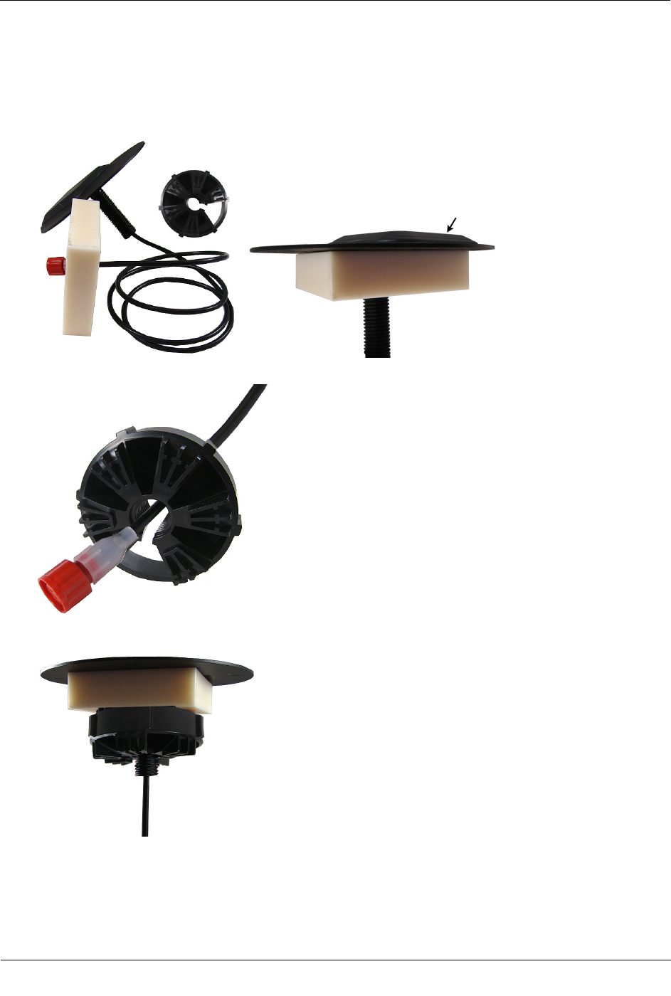
To install the remote antenna through a pit lid
1. Thread the remote antenna connector and cable through the pit lid hole. Verify the antenna's convex
surface is on the top of the pit lid. (These instructions show a simulated pit lid material.)
2. Insert the antenna connector through the rectangular opening in the threaded collar.
3. Turn the threaded collar until it is tight against bottom of the pit lid.
Optional Direct Connect Remote Antenna Installation
TDC
-0909-006 100W/100W+ and 100WP/100WP+ Datalogging Water ERT Module Installation Guide 37
Proprietary and Confidential
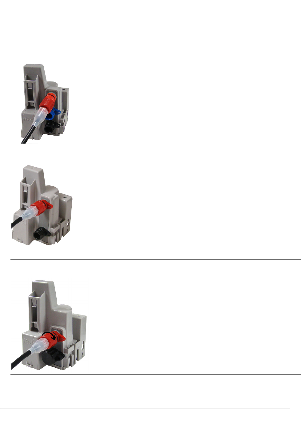
To connect the remote antenna to the ERT module
1. Align the connector pins with the top, red connector on the ERT module. The illustration shows a 3-port
ERT module connection.
2. Push in the antenna connector to complete the connection. The illustration shows a two-port ERT module
connection.
3. Turn the connector lock ring to the right to secure the connection.
Caution Turn the connector lock-ring only. Do not twist the completed connection. Twisting the
connection could damage the ERT module or antenna connector pins.
4. Follow the Rod Mount Installation on page 15 or Wall Mount Installation on page 18 instructions to
mount the ERT module.