Itron 100WD AMR tranceiver device for utility meters User Manual 3
Itron Inc AMR tranceiver device for utility meters Users Manual 3
Itron >
Contents
Users Manual 3
Installing the 100W/100W+ and 100WP/100WP+ ERT Module
TDC
-0909-006 100W/100W+ and 100WP/100WP+ Datalogging Water ERT Module Installation Guide 20
Proprietary and Confidential
Shelf Mount Installation
This section describes 100W/100W+ and 100WP/100WP+ ERT module installation using a shelf mount
adapter to mount the ERT module in a pit lid slot.
Caution Observe the following guidelines for mounting the ERT module using the shelf
mount procedure:
• ERT module positioning other than upright could negatively affect radio
performance and battery life.
• Use only Itron-approved splice kits or inline connectors.
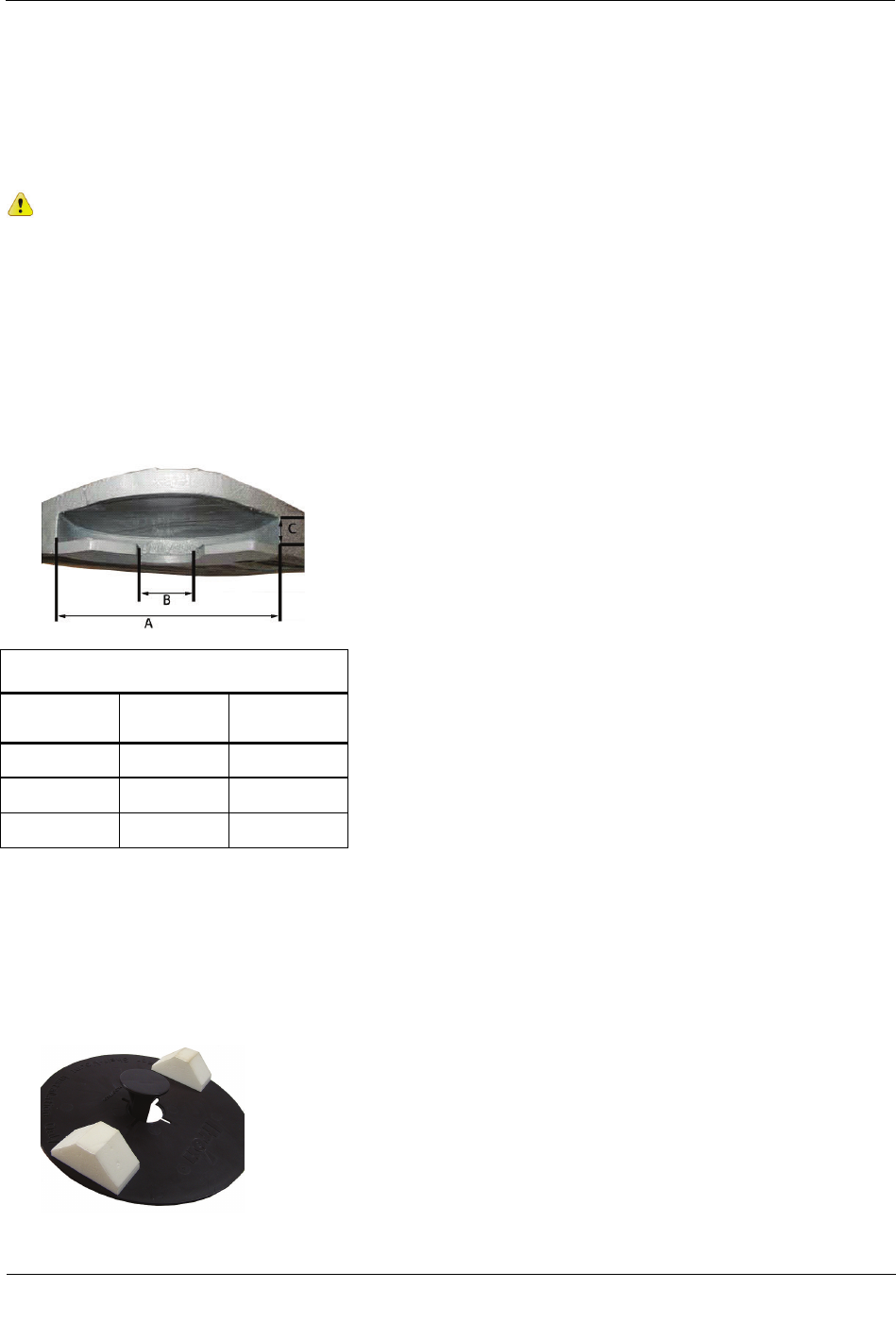
The pit lid and slot must have the correct dimensions for the ERT module assembly to fit
properly.
The following illustration and the accompanying table give pit lid slot dimensions for the shelf mount
installation method.
Pit Lid Slot Dimensions
Dimension
Minimum
(inches)
Maximum
(inches)
A 6 3/4 N/A
B 2 5 3/4
C 3/4 1
Required Hardware
Itron 100W Series Shelf Mount Kit
To install using the shelf mount adapter
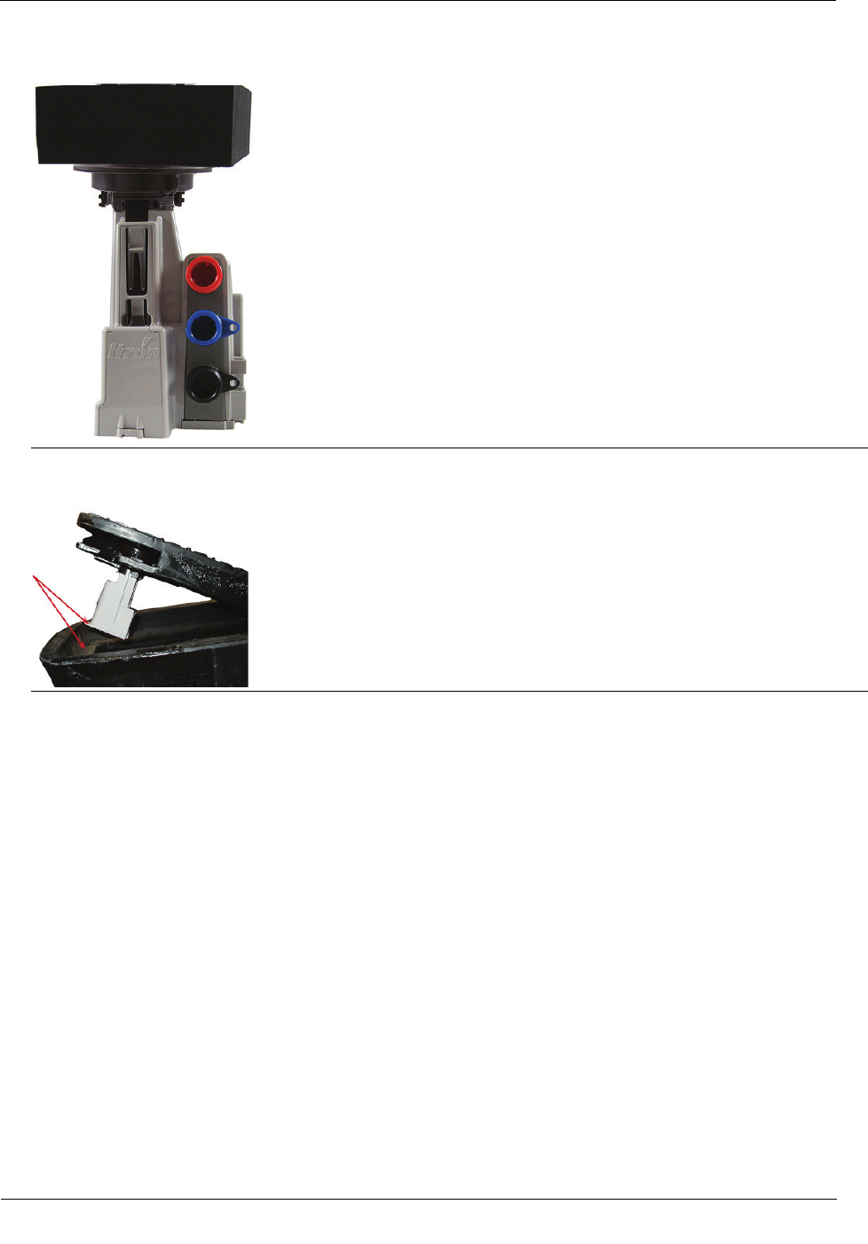
1. With the foam spacers facing up, insert the shelf mount adapter into the opening in the disk.
Installing the 100W/100W+ and 100WP/100WP+ ERT Module
TDC
-0909-006 100W/100W+ and 100WP/100WP+ Datalogging Water ERT Module Installation Guide 21
Proprietary and Confidential
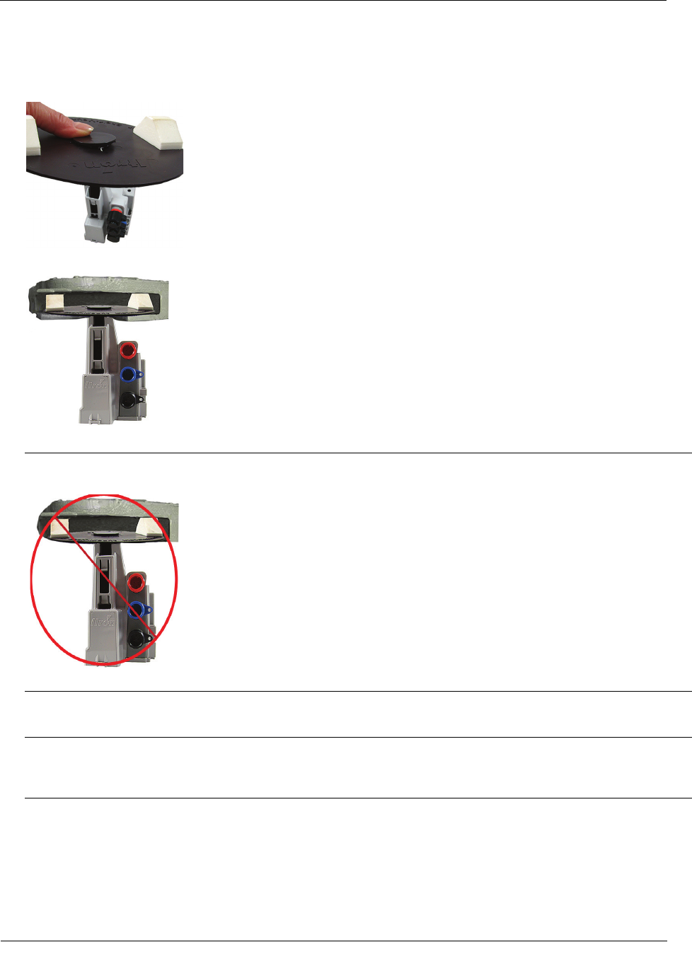
2. Push the adapter into the opening gently until the adapter snaps into place. Insert the shelf mount adapter
into the ERT module antenna slot pushing firmly with your thumb until the adapter tab locks into place in
the ERT module antenna slot opening.
3. Slide the adapter assembly into the pit lid with the foam spacers positioned on each side of the pit lid slot.
Correct position for foam spacers
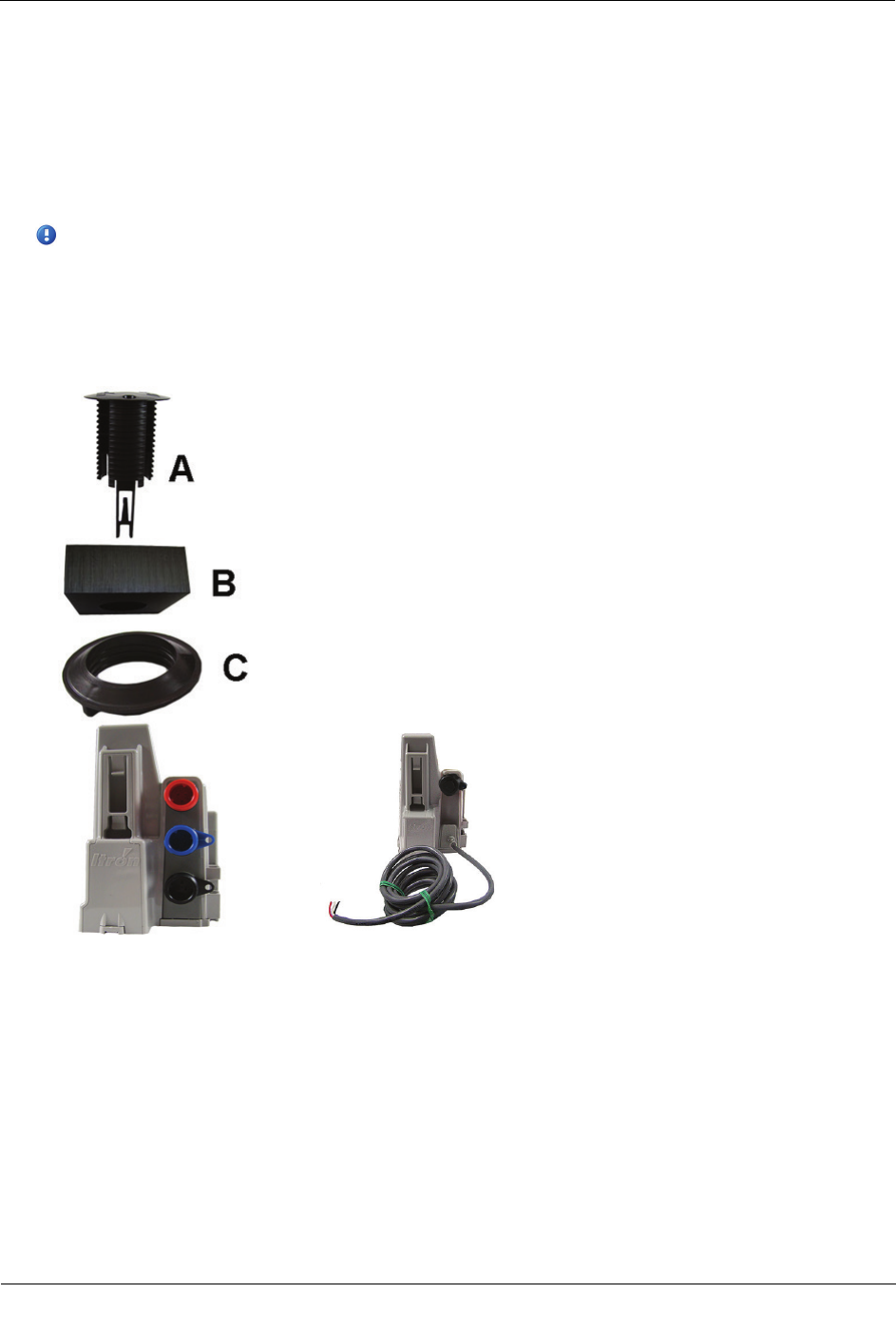
Caution Do not install the adapter assembly in a manner that provides little or no support under disk's
edge.
Incorrect mounting position for foam spacers.
4. The installed ERT module position must be vertical and upright when the lid is replaced on the pit.
Caution When placing the pit lid on to the pit box after the shelf mount adapter installation, use care to
avoid pinching or damaging the ERT module to meter cable. Any ERT module position other than upright
may negatively affect radio performance and battery life.
Through Lid Installation
This section provides instructions to mount the 100W/100W+ and 100WP/100WP+ ERT module in a pit lid
with a drilled, round 1-3/4-inch, 1-7/8-inch, or 2-inch hole.
Installing the 100W/100W+ and 100WP/100WP+ ERT Module
TDC
-0909-006 100W/100W+ and 100WP/100WP+ Datalogging Water ERT Module Installation Guide 22
Proprietary and Confidential
Through Lid Mount Required Tools and Hardware
This mounting method requires the Pit Lid Mounting Kit. Refer to the 100W Installation Methods Overview
(PUB-1300-004) for guidance on which kit to install for different pit lid material and traffic conditions.
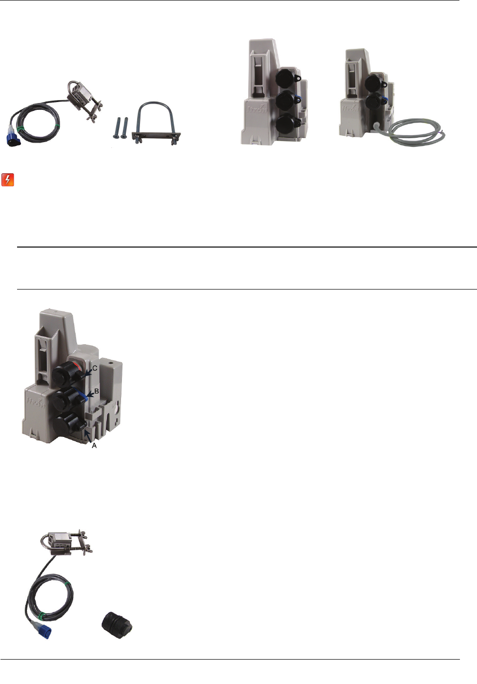
Pit Lid Mounting Kit (CFG-1300-004)
Note The Pit Lid Mounting Kit is not intended for applications involving vehicular traffic.
Use the Remote Antenna Kit in incidental traffic areas (such as residential environments).
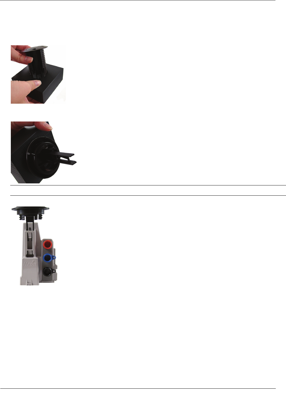
This section provides the instructions to install the 100W/100W+ and 100WP/100WP+ ERT module in a pit
lid with a hole using the Pit Lid Mounting Kit (CFG-1300-004). Verify you have the following items to
complete the installation.
A
Retainer clip
B Pit lid with a pre-drilled hole (simulated pit lid material shown)
C Retainer clip collar
D
100W/100W+ and 100WP/100WP+ ERT module
Installing the 100W/100W+ and 100WP/100WP+ ERT Module
TDC
-0909-006 100W/100W+ and 100WP/100WP+ Datalogging Water ERT Module Installation Guide 23
Proprietary and Confidential
To install in lids with holes using the Pit Lid Mounting Kit (CFG-0771-011)
1. Insert the retainer clip into the pit lid hole with the convex surface on the top of the pit lid.
2. From the bottom side of the lid, screw on the threaded retainer clip collar until the beveled top rests
against the pit lid.
Note Ensure the beveled edge of the clip collar is toward the top of the pit lid.
3. Align and insert the retainer clip tab into the retainer clip receptacle on the ERT module housing.
Installing the 100W/100W+ and 100WP/100WP+ ERT Module
TDC
-0909-006 100W/100W+ and 100WP/100WP+ Datalogging Water ERT Module Installation Guide 24
Proprietary and Confidential
4. Verify the clip locks into place in the housing.
Caution Carefully align the ERT module through lid assembly. If the assembly is improperly aligned, the
pit lid may not close.
Pit lid mounting installation is complete.
Optional Leak Sensor Installation
This section describes installation of the Leak Sensor (LS) in a 100W/100W+ and 100WP/100WP+ ERT
module system.
The ERT module stores 20 days of LS data. On the 21st day, the ERT module begins to write over stored data
in a first in, first out manner.
The ERT module automatically detects the presence of connected LS devices. The ERT module will
automatically detect the LS within 22.5 minutes and begin reading LS data. To immediately detect the LS and
begin reading data, perform a Check ERT with a handheld computer running FDM software.
The LS is used in conjunction with both indoor (basement) and outdoor (mounting on the exterior of the
house) 100W/100W+ and 100WP/100WP+ ERT module installations. LS devices are mounted on a water
service pipe or meter insetter (meter horn) and connect to the LS connector on the ERT module as described
in To connect the Leak Sensor to the 100W/100W+ and 100WP/100WP+ ERT module on page 26. The
mounting bracket shipped with the LS accommodates an (up to) 1-1/2-inch OD pipe. An optional mounting
bracket is available for pipe sizes (up to 2 1/2-inch OD).

Installing the 100W/100W+ and 100WP/100WP+ ERT Module
TDC
-0909-006 100W/100W+ and 100WP/100WP+ Datalogging Water ERT Module Installation Guide 25
Proprietary and Confidential
Leak Sensor Installation Equipment
Equipment
Itron Part
Number
Description
Leak Sensor
LDS-0001-002
LS with inline connector, environmental connector cap; 5-foot cable, and
mounting bolt (fits up to 1 1/2-inch OD pipe).
Optional mounting bracket CFG-0349-002 Mounting bolt fits up to 2 1/2-inch OD pipe.
ERT module
100W three-port ERT module ERW-1300-203 Triple port encoder ERT module for connection to register, Leak Sensor,
and optional remote antenna.
100W+ three-port ERT module ERW-1300-303 Triple port encoder ERT module for connection to register, Leak Sensor,
and optional remote antenna, ISM
100W, 5-ft. flying leads, two-port
ERT module
ERW-1300-206 Three-port encoder ERT module for connection to register using 5-ft. flying
leads, Leak Sensor and optional remote antenna connection with inline
connectors.
100W+, 5-ft. flying leads, two-port
ERT mo dule
ERW-1300-306
Thre e-port encoder ERT module for connection to register using 5-ft. flying
leads, Leak Sensor and optional remote antenna connection with inline
connectors, ISM
100W, 20-in. flying leads, three-port
encoder ERT module
ERW-1300-218 Three-port encoder ERT module for connection to register using 20-in.
flying leads, Leak Sensor, and optional remote antenna connection with
inline connectors.
100W+, 20-in. flying leads, three-
port encoder ERT module
ERW-1300-318 Thre e-port encoder ERT module for connection to register using 20-in.
flying leads, Leak Sensor, and optional remote antenna connection with
inline connectors, ISM
100WP three-port ERT module
ERW-1300-209
Thre e-port pulser ERT module for connection to register, Leak Sensor, and
optional remote antenna.
100WP +three-port ERT module
ERW-1300-309
Thre e-port pulser ERT module for connection to register, Leak Sensor, and
optional remote antenna, ISM
100WP, 5-ft. flying leads, two-port
ERT module
ERW-1300-212
Thre e-port pulser ERT module for connection to register using 5-ft. flying
leads, Leak Sensor, and optional remote antenna connection with inline
connectors.
100WP+, 5-ft. flying leads, two-port
ERT module
ERW-1300-312
Thre e-port pulser ERT module for connection to register using 5-ft. flying
leads, Leak Sensor, and optional remote antenna connection with inline
connectors, ISM
100WP, 20-in. flying leads, three-
port pulser ERT module
ERW-1300-220 Three-port pulser ERT module for connection to register using 20-in. flying
leads, Leak Sensor, and optional remote antenna connection with inline
connectors.
100WP+, 20-in. flying leads, three-
port pulser ERT module
ERW-1300-320
Thre e-port pulser ERT module for connection to register using 20-in. flying
leads, Leak Sensor, and optional remote antenna connection with inline
connectors, ISM
25-foot extension cable (optional)
CFG-0349-101
25-foot cable with coordinating connectors (LS blue connector, register
black connector).
100W LS environmental
replacement cap
MSC-0019-008
Protects Leak Sensor connector when the LS is not connected to the 100W
ERT module.
Itron Security Seal
MSC-0018-001
Indicates module tampering and ensures the protective cover stays intact.
Installing the 100W/100W+ and 100WP/100WP+ ERT Module
TDC
-0909-006 100W/100W+ and 100WP/100WP+ Datalogging Water ERT Module Installation Guide 26
Proprietary and Confidential
Leak Sensor Optional Mounting Bracket 3-port Module Two-port/flying lead module
Warning When the 100W/100W+ or 100WP/100WP+ is installed but the LS is not attached, you
must protect the blue port with the universal environmental cap (MSC-0019-008). If you remove
the LS from the ERT module, the environmental cap must be replaced to protect the connector.
To connect the Leak Sensor to the 100W/100W+ and 100WP/100WP+ ERT module
Caution Verify you have the correct 100W/100W+ or 100WP/100WP+ ERT module. Leak Sensors must
mount to Port B (middle blue port) of the ERT module. Connecting the LS to Port A (bottom port) or Port
C (top port) will cause electrical damage to the LS and ERT module.
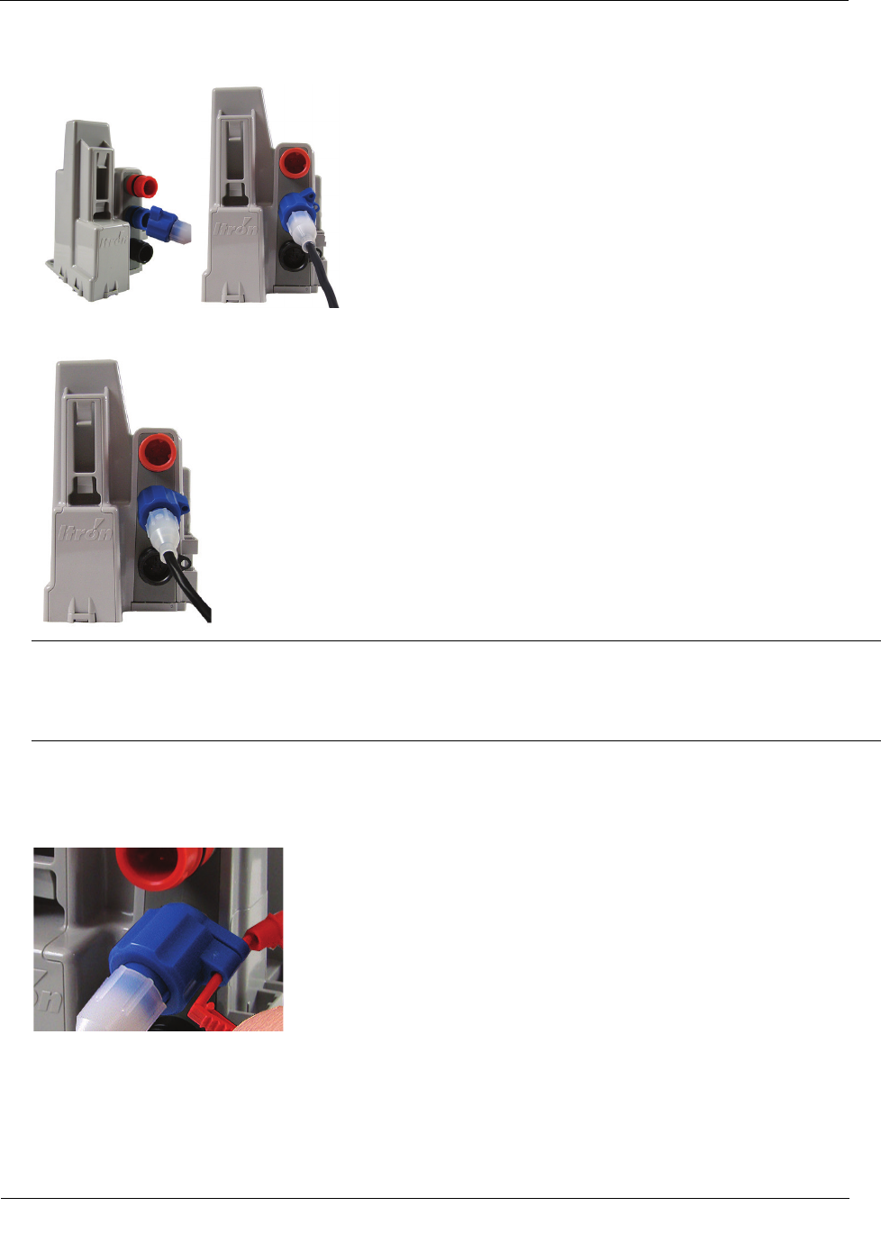
1. Remove the environmental cap from the ERT module's blue connector (B).
C. Red connector: Optional antenna connection
B. Blue connector: Leak Sensor connection
A. Black connector: register connection
2. Remove the environmental cap from the Leak Sensor connector. Verify the connectors (the ERT module's
LS connector and the Leak Sensor connector) are clean and dry.
Installing the 100W/100W+ and 100WP/100WP+ ERT Module
TDC
-0909-006 100W/100W+ and 100WP/100WP+ Datalogging Water ERT Module Installation Guide 27
Proprietary and Confidential
3. Align the Leak Sensor connector with the ERT module's blue connector and insert.
4. Rotate the connector locking ring until the security holes align.
Caution Do not force the connector ends together. While you hold the LS connector, engage the ERT
module's connector by rotating the locking ring until both connectors securely connect. Twist only the
connector locking ring, not the body of the connector. Twisting the connector body could damage the
connector's pins.
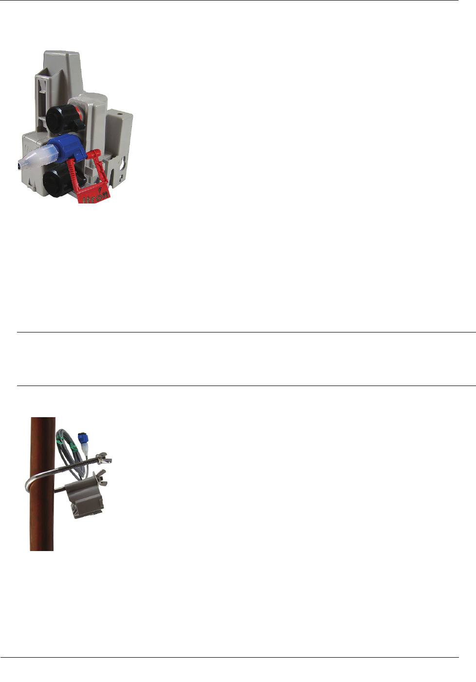
To attach an Itron Security Seal through the connector security hole
1. Insert the pointed end of the security seal through the inline connector and the ERT module connector
security holes.
Installing the 100W/100W+ and 100WP/100WP+ ERT Module
TDC
-0909-006 100W/100W+ and 100WP/100WP+ Datalogging Water ERT Module Installation Guide 28
Proprietary and Confidential
2. Insert the pointed end of the security seal into the capped end and push until the seal locks.
This completes the ERT module and Leak Sensor connections.
Pipe Preparation
Clean any dust or dirt from the pipe to facilitate direct contact with the LS surface.
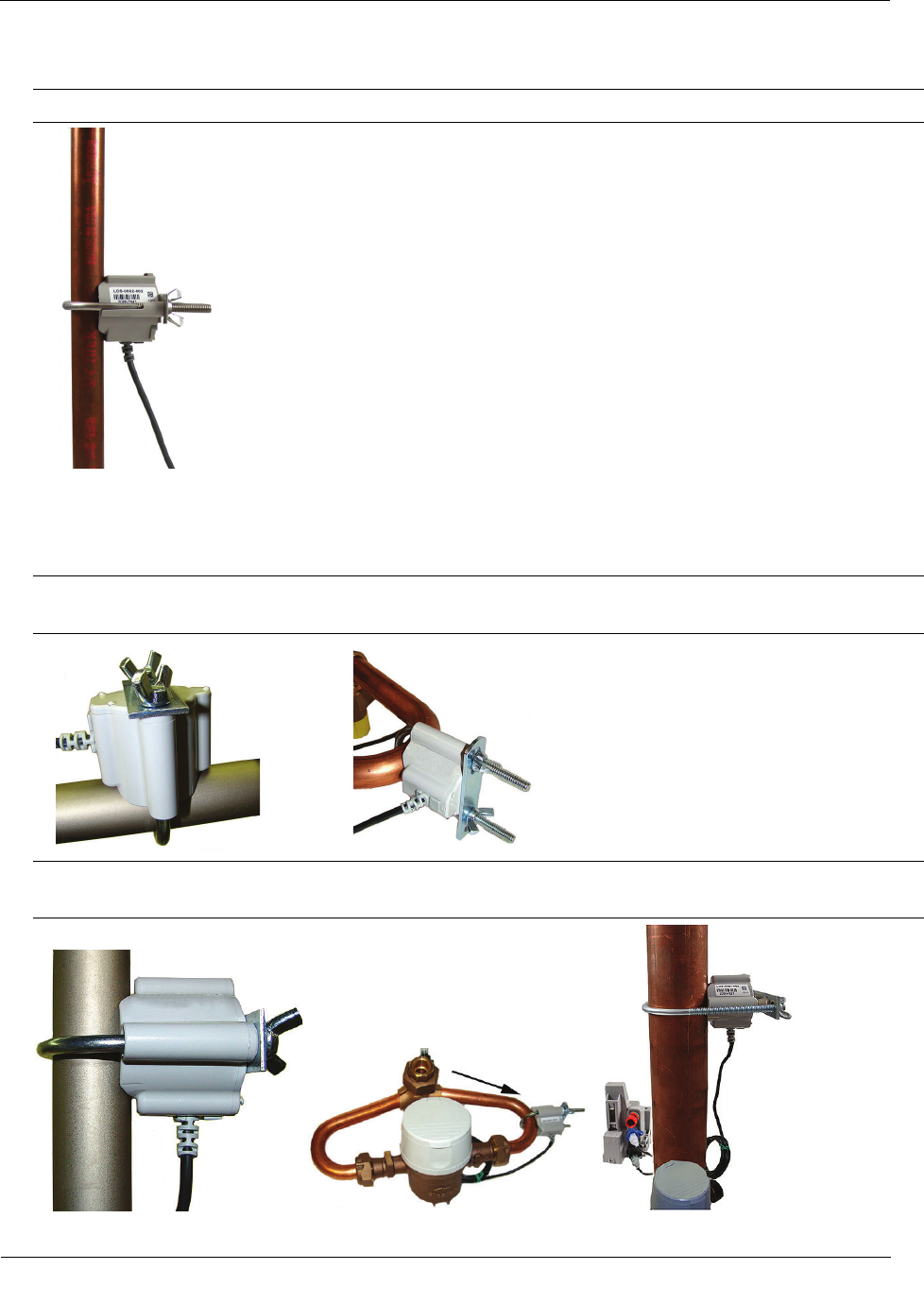
To install the Leak Sensor on a pipe or meter insetter
1. Select a Leak Sensor mounting location within 5-feet of the ERT module. Mount the sensor on the water
input side of the meter.
Caution Mount the Leak Sensor on the water input side of the meter. Failure to follow this mounting
requirement could result in errors in the leak detection data. Installation requires Itron mounting hardware.
Repair costs and service charges relating to the use on non-compliant mounting hardware will be charged
to the customer. Contract Itron Support for more information.
2. Verify the pipe’s mounting surface is free from dirt and debris. Place the curved surface of the LS against
the pipe.
Installing the 100W/100W+ and 100WP/100WP+ ERT Module
TDC
-0909-006 100W/100W+ and 100WP/100WP+ Datalogging Water ERT Module Installation Guide 29
Proprietary and Confidential
3. Insert the mounting U-bolt over the pipe and into the LS mounting holes.
Caution Do not mount the Leak Sensor on a pipe coupler, joint, or nut.
4. Insert the mounting plate over the U-bolt's threaded screw ends. Attach the two wing nuts over the clamp
screw ends and tighten the wing nuts until snug (to a minimum of 5-inch pounds) to prevent device
rotation on the pipe. After you tighten the second wing nut, check the Leak Sensor to verify the device is
snug. If the sensor moves, tighten the wing nuts until there is no movement.
Caution Do not tighten the Leak Sensor to more than 20 inch-pounds. Over-tightening could damage the
Leak Sensor housing and/or the pipe.
Note Leak Sensor mounting orientation is not critical. Orient the sensor to best accommodate your
installation. The most important installation practice is to mount the sensor securely to the pipe.