Itron 100WD AMR Transceiver device for utility meters User Manual P3
Itron Inc AMR Transceiver device for utility meters Users Manual P3
Itron >
Contents
Users Manual P3
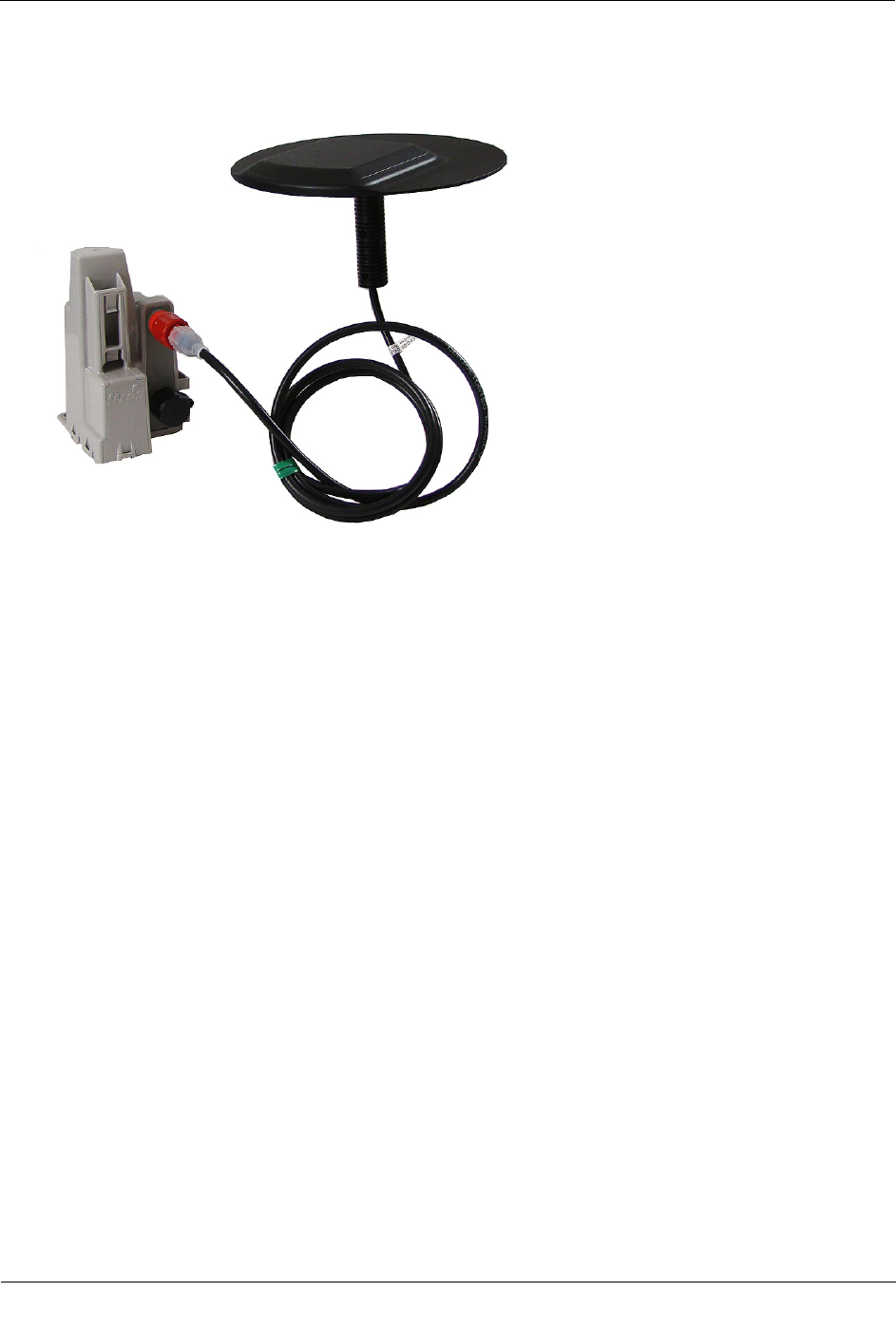
Optional Direct Connect Remote Antenna Installation
TDC
-0909-006 100W/100W+ and 100WP/100WP+ Datalogging Water ERT Module Installation Guide 38
Proprietary and Confidential
Remote antenna installation is complete.
TDC
-0909-006 100W/100W+ and 100WP/100WP+ Datalogging Water ERT Module Installation Guide 39
Proprietary and Confidential
This section describes the 100W/100W+ and 100WP/100WP+ ERT module connections to the water meter
register using the inline connector assembly. Follow the manufacturer's recommended procedure for installing
the water meter register on the meter.
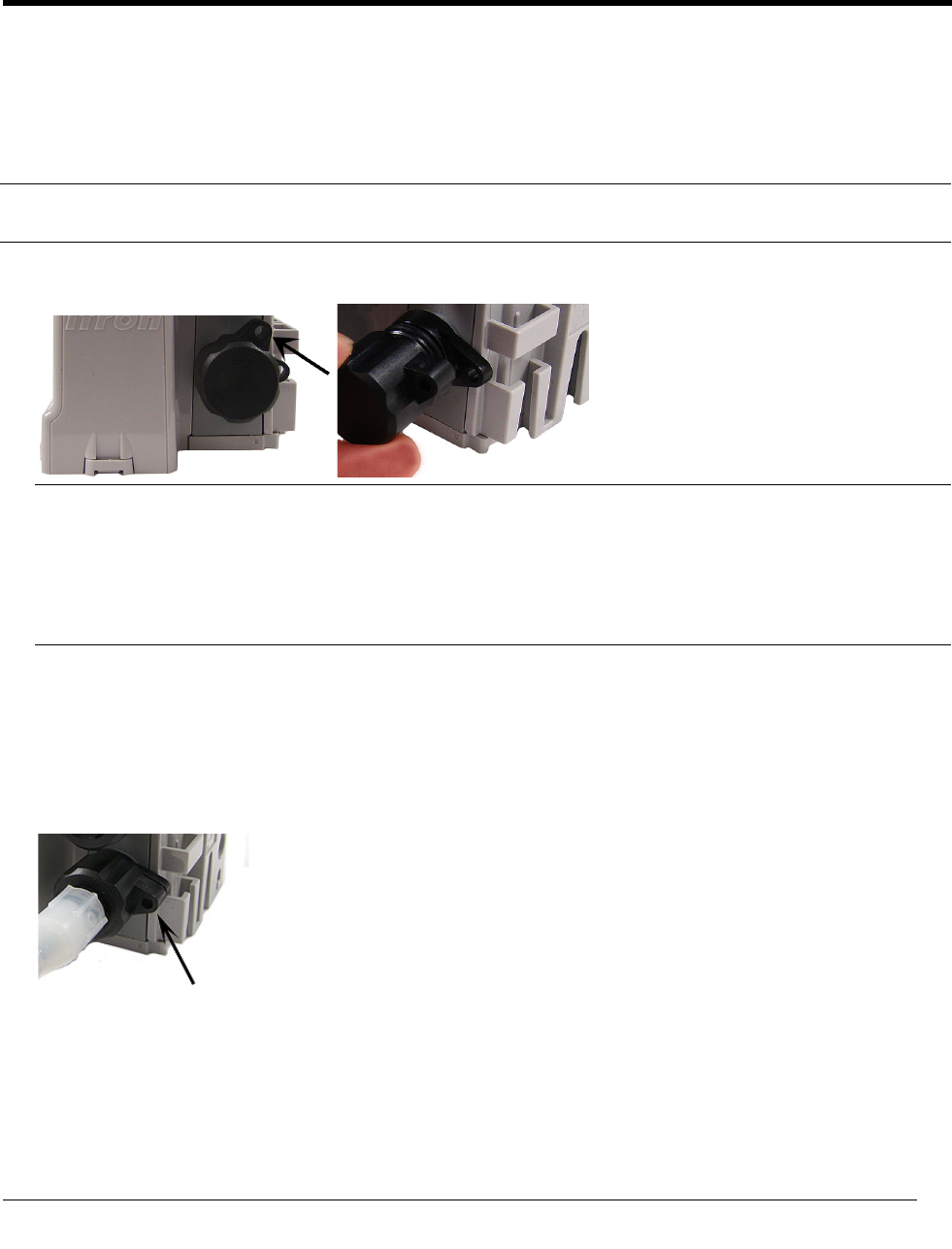
To connect the inline connector
Note If an inline connector is not used and the ERT module is already connected to the water meter register,
skip this step.
1. Remove the protective cover from the connector by twisting the two halves in opposite directions. Pull the
halves apart.
Caution Verify the connector halves are clean and dry before assembly.
If any of the following conditions occur, do not install the ERT modules:
• Any of the three pins are damaged or missing.
• The O-ring is missing.
• The cable is cut or nicked.
2. Connect the register cable to the ERT module connector:
• Holding the connectors by the black shells, rotate one end to align the keyed slots.
• Push until snug.
• Slide the black coupling nut over the O-ring. Make sure the O-ring stays seated. (If the O-ring does
not stay seated, disconnect and repeat this step.)
• Twist the register cable's black coupling nut to align the two tabs.
APPENDIX A
U
sing an Inline Connector
Using an Inline Connector
TDC
-0909-006 100W/100W+ and 100WP/100WP+ Datalogging Water ERT Module Installation Guide 40
Proprietary and Confidential
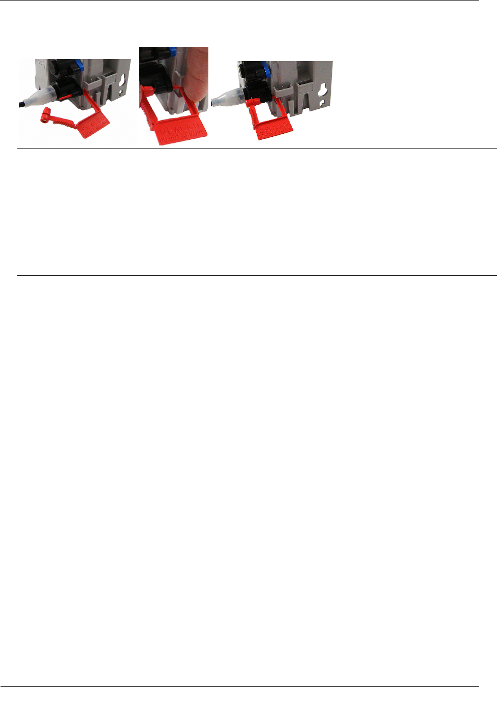
3. Install the security seal as shown. Push it until it snaps into place.
Note For future meter or ERT module servicing, break the security seal by pulling the seal apart. The
original protective connector covers can be reused if kept clean and dry. Install a new security seal after
servicing either device. To order replacement security seals, see the Water ERT Module Ordering Guide
(PUB-0063-001).
Caution Shield connectors with protective environmental covers (see 100W/100W+ and
100WP/100WP+ ERT Module Mounting Accessories on page 14). Do not leave an exposed connector in
the field.
Environmental caps employ multiple seals to increase cap life. Environmental cap design allows utilities
to install the ERT module and install a Leak Sensor or optional remote antenna at a future date.
TDC
-0909-006 100W/100W+ and 100WP/100WP+ Datalogging Water ERT Module Installation Guide 41
Proprietary and Confidential
This section describes connecting the 100W/100W+ and 100WP/100WP+ ERT module with flying leads to
the water meter register using the Itron Splice Kit.
Caution ERT module wire terminations must be properly sealed with a non-conductive gel
material to prevent water intrusion (otherwise, this configuration should not be used in a pit box
environment). Itron recommends the 5-foot or 20-inch cable configuration for OEM users only.
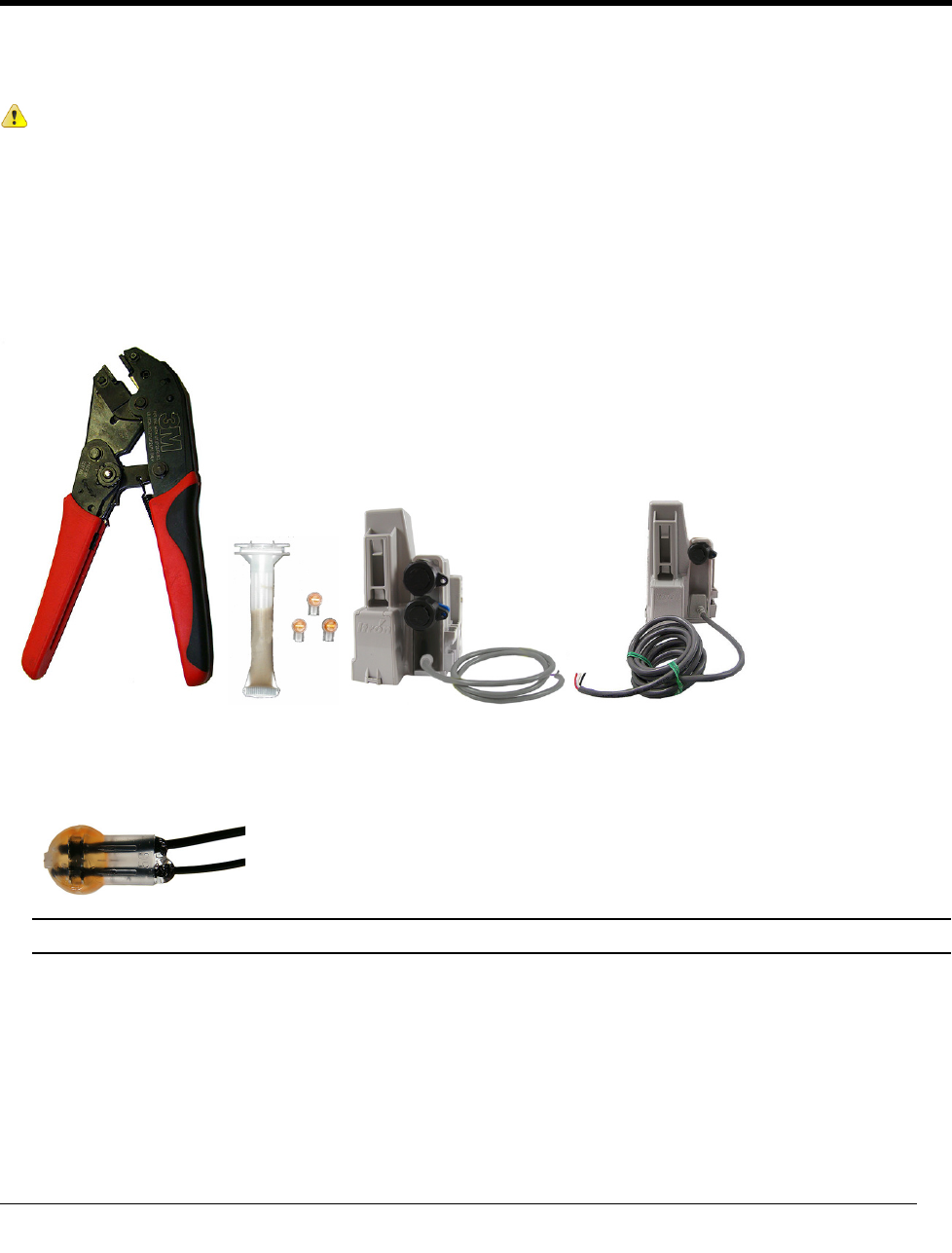
Required Materials
• E-9R 3M® gel cap crimping tool
• Itron Splice Kit (OEM-0034-002)
• 100W/100W+ and 100WP/100WP+ ERT Module with flying leads
To install the Itron splice kit
1. Push the corresponding register and ERT module wires as far as possible into the connector.
Caution Do not strip insulation from the ends of the wires before inserting them into the connector.
APPENDIX B
U
sing the Itron Splice Kit
Using the Itron Splice Kit
TDC
-0909-006 100W/100W+ and 100WP/100WP+ Datalogging Water ERT Module Installation Guide 42
Proprietary and Confidential
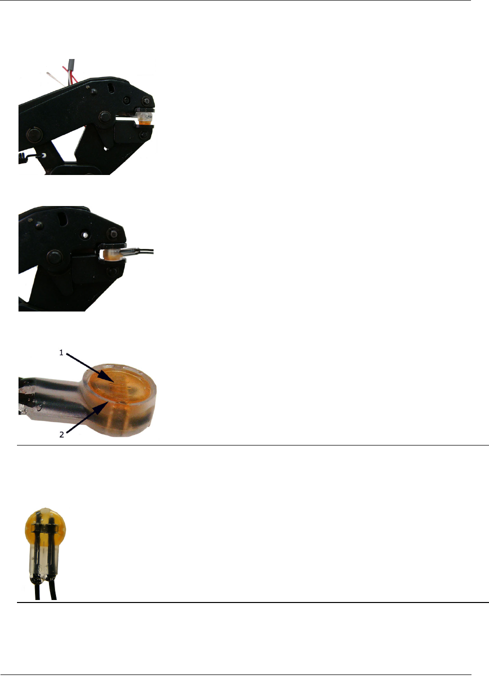
2. Carefully place the connector and wires into the jaws of the crimping tool. Make sure the wires remain
fully inserted in the gel-cap connector.
3. Crimp the connector by squeezing the handles until the connector cap is fully seated. Continue to apply
pressure for three seconds.
4. A connector is crimped properly when the top of the movable yellow center (1) is flush with the top of the
connector body (2).
Warning Crimping the connector forces some sealant out of connector. The sealant protects the inside of
the connector against insects, moisture, and other contaminants. The sealant may cause minor eye and
skin irritation. Avoid eye contact. Avoid prolonged or repeated skin contact. Contact Itron Support for
Material Safety Data Sheets (MSDS).
Using the Itron Splice Kit
TDC
-0909-006 100W/100W+ and 100WP/100WP+ Datalogging Water ERT Module Installation Guide 43
Proprietary and Confidential
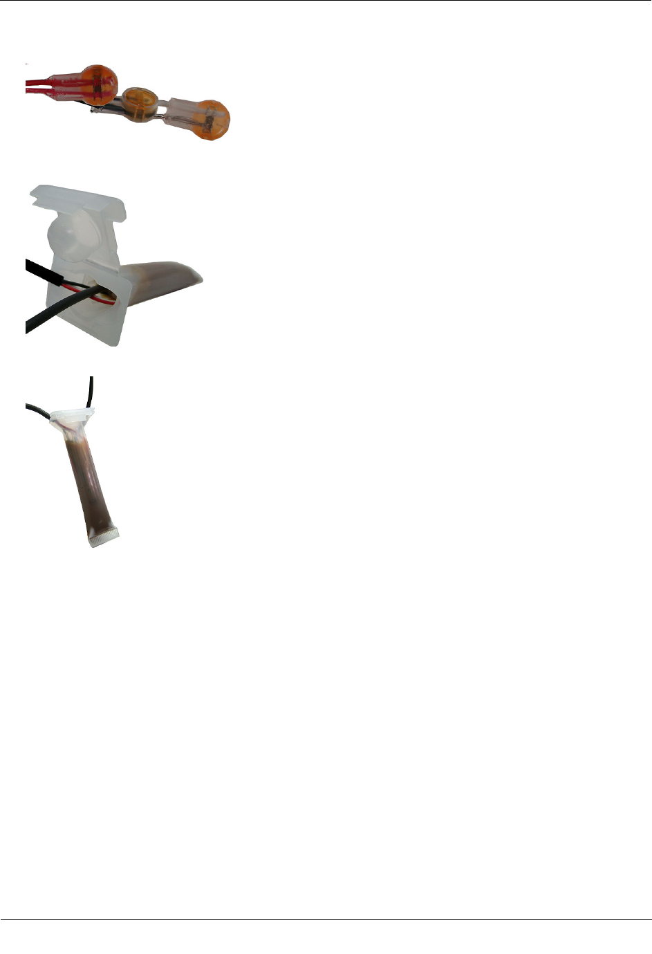
5. After you complete all ERT module to register wire connections, arrange the connectors in a single file.
6. Insert the connectors and wires into the splice tube until the connectors and wires completely immerse in
the tube's gel material.
7. Separate the cables to the sides and close the splice tube cover.
8. Discard any leftover materials from the customer premises.
TDC
-0909-006 100W/100W+ and 100WP/100WP+ Datalogging Water ERT Module Installation Guide 44
Proprietary and Confidential
This section describes the procedure for installing Itron cable armor in a field installation. The Itron armor
cable provides a layer of protection for the module's cable jacket. Itron cable armor is available in 5-foot
sections.
Warning Itron armor cable is stainless steel and may have sharp edges. Use caution when you are
installing the armor cable.
Important If you remove the inline connector from the ERT module to install the armor cable, you
must use an Itron handheld to reprogram the ERT module using FDM Endpoint Tools. Perform a
Check Endpoint function (with in FDM Endpoint Tools) after you reprogram the ERT module to
verify communication with the meter register.
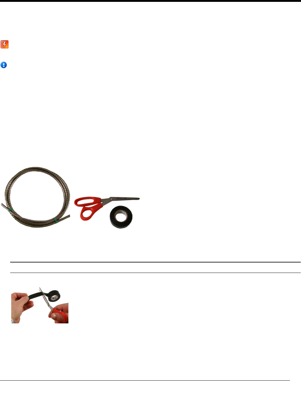
Required Materials
The following materials are required to install the Itron cable armor.
• 5-foot Itron cable armor
• Electrical tape
• (Optional) Scissors
To install the Itron cable armor
1. Remove the ERT module from the pit.
Note If it is possible in your field installation, keep the ERT module connected to the register.
2. Cut a two to three inch strip of electrical tape.
APPENDIX C
U
sing the Itron Cable Armor
Using the Itron Cable Armor
TDC
-0909-006 100W/100W+ and 100WP/100WP+ Datalogging Water ERT Module Installation Guide 45
Proprietary and Confidential
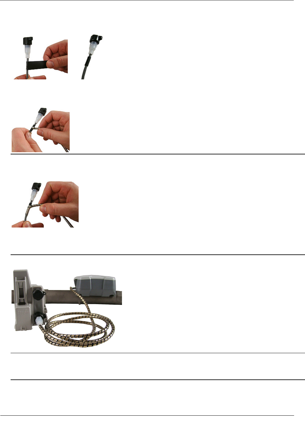
3. Wrap the entire piece of electrical tape around the ERT module cable near the inline connector.
4. Beginning over the installed electrical tape, twist the Itron cable armor onto the ERT module cable using a
right-handed twist.
Important You must twist—not wrap—the cable armor onto the ERT module cable. Wrapping the cable
armor can cause the stainless steel jacket to warp.
Warning You must begin wrapping the cable armor over portion of the cable protected by the electrical
tape. If you do not begin to wrap the cable armor over the protected portion of the ERT module cable, a
cut cable could cause an ERT module/register communication failure.
5. Continue to twist the cable armor onto the ERT module cable until the cable armor covers the entire cable.
Warning You must continue to wrap the cable armor onto the cable protected by the electrical tape. If
you do not twist the cable armor over the protected portion of the cable, you cut initiate a cut cable and
cause and ERT module/register communication failure.
6. Remove any leftover materials from the customer premises. Discard or recycle leftover materials.

TDC
-0909-006 100W/100W+ and 100WP/100WP+ Datalogging Water ERT Module Installation Guide 46
Proprietary and Confidential
The following information is provided to help you troubleshoot issues related to the 100W/100W+ and
100WP/100WP+ ERT modules.
The following table describes possible issues and provides suggested actions to resolve the issue.
Issue
Action
Cannot program the ERT module. Check the programming device and software version. Program ERT
modules using the FC300 handheld computer running Field Deployment
Manager (FDM) software.
Cannot read the ERT module. An ERT module that is not programmed will not transmit an
SCM/SCM+. Reprogram the ERT module and perform a reread. If an
ERT module is not initially programmed, it will not bubble-up and listen
for an SCM/SCM+.
The encoder ERT module is reporting an invalid read. An encoder ERT module that has set the Last Good Read flag will cause
an Invalid Read to display in the FDM Consumption field.
Marginal readability due to water ERT module location
(for example, an ERT module deep inside a pit).
Consider reprogramming the ERT module for Hard-to-read (H2R)
mode. This increases the output power to Fixed Network levels.
Note Hard-to-read mode will reduce battery life.
The ERT module in a Fixed Network is not reporting. Perform a Check ERT and verify the ERT module is in FN mode. If the
CCU's pathway is obstructed, consider including an 8-channel repeater.
Systems that utilize Fixed Network v4.0 software and a CCU100 may
require a Repeater 100.
The handheld programmer is locked up and button presses
produce no response.
Soft boot the handheld by pressing and holding buttons A and B until the
screen fades. Release the buttons and allow the handheld to reboot.
APPENDIX D
T
roubleshooting

TDC
-0909-006 100W/100W+ and 100WP/100WP+ Datalogging Water ERT Module Installation Guide 47
Proprietary and Confidential
Symbols & Numbers
100W/100W+ and 100WP/100WP+ ERT Module
installation • Error! Bookmark not defined.
100W/100W+ and 100WP/100WP+ ERT Module
models • Error! Bookmark not defined.,
Error! Bookmark not defined.
100W/100W+ and 100WP/100WP+ ERT Module
transmission modes • Error! Bookmark not
defined.
100W/100W+ and 100WP/100WP+ ERT Module
with integral connectors • Error! Bookmark
not defined.
100W/100W+ encoder start-up • Error!
Bookmark not defined.
100W/100W+ operating modes • Error!
Bookmark not defined.
100WP/100WP+ operating modes • Error!
Bookmark not defined.
100WP/100WP+ pulser start-up • Error!
Bookmark not defined.
A
about the 100W/100W+ and 100WP/100WP+
ERT Module • Error! Bookmark not defined.
B
base mount installation • Error! Bookmark not
defined.
battery life • Error! Bookmark not defined.
before you begin • Error! Bookmark not
defined.
C
cable armor • Error! Bookmark not defined.
connecting the 100WP/100WP+ to a remote meter
register • Error! Bookmark not defined.
H
how this document is organized • Error!
Bookmark not defined.
I
initializing the 100W/100W+ • Error! Bookmark
not defined.
initializing, connecting, and programming the ERT
module • Error! Bookmark not defined.
installing the 100W/100W+ and 100WP/100WP+
ERT Module • Error! Bookmark not defined.
installing the remote antenna • Error! Bookmark
not defined.
L
Leak Sensor installation equipment • Error!
Bookmark not defined.
O
optional direct connect remote antenna installation
• Error! Bookmark not defined.
optional Leak Sensor installation • Error!
Bookmark not defined.
P
pipe preparation • Error! Bookmark not defined.
programming the 100WP/100WP+ • Error!
Bookmark not defined.
R
related documents • Error! Bookmark not
defined.
required hardware • Error! Bookmark not
defined., Error! Bookmark not defined.,
Error! Bookmark not defined., Error!
Bookmark not defined.
rod mount installation • Error! Bookmark not
defined.
S
security • Error! Bookmark not defined.
shelf mount installation • Error! Bookmark not
defined.
T
through lid installation • Error! Bookmark not
defined., Error! Bookmark not defined.
U
using an extension cable • Error! Bookmark not
defined.
Index

Index
TDC
-0909-006 100W/100W+ and 100WP/100WP+ Datalogging Water ERT Module Installation Guide 48
Proprietary and Confidential
using an inline connector • Error! Bookmark not
defined.
using the Itron splice kit • Error! Bookmark not
defined.
V
verifying 100W/100W+ and 100WP/100WP+
ERT Module operation • Error! Bookmark not
defined.