Itron 100WD AMR transceiver decive for utility meters User Manual Users Guide 3
Itron Inc AMR transceiver decive for utility meters Users Guide 3
Itron >
Contents
Users Guide 3
Installing the 100W/100W+ and 100WP/100WP+ ERT Module
TDC
-0909-006 100W/100W+ and 100WP/100WP+ Datalogging Water ERT Module Installation Guide 30
Proprietary and Confidential
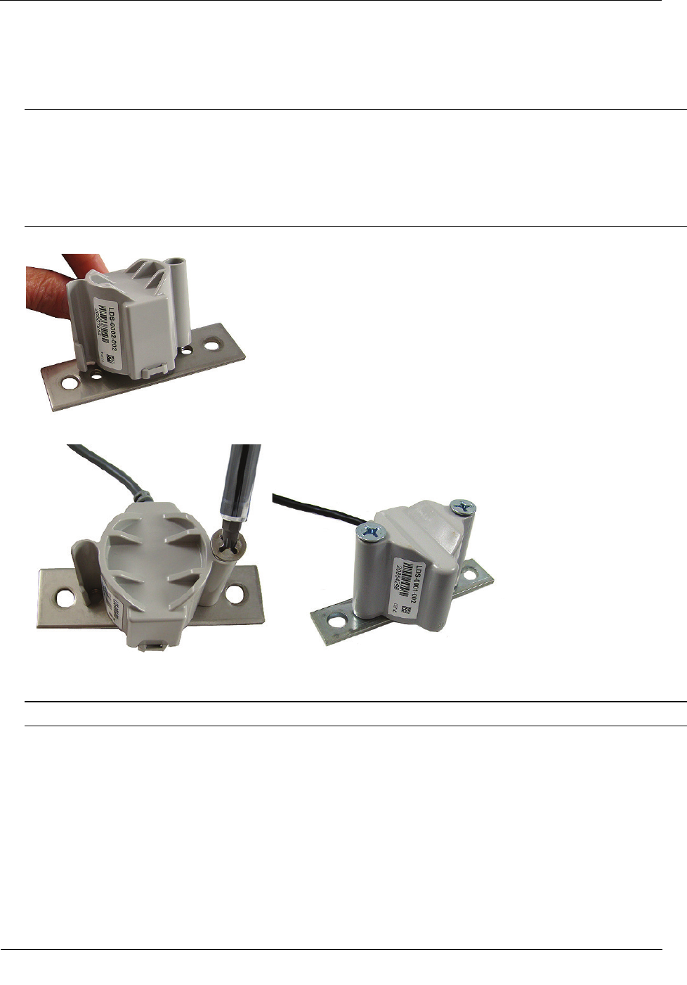
To install the Leak Sensor on a pipe (up to 2 1/2-inch OD)
1. Select a Leak Sensor mounting location within 5 feet of the ERT module.
Note Leak Sensor mounting orientation is not critical. Orient the sensor to best accommodate your
installation. The most important installation practice is to fasten the sensor securely to the pipe.
Caution Mount the Leak Sensor on the water input side of the meter. Failure to follow this mounting
requirement could result in errors in the leak detection data. Installation requires Itron mounting hardware.
Repair costs and service charges relating to the use on non-compliant mounting hardware will be charged
to the customer. Contract Itron Support for more information.
2. Insert the mounting plate screws into the holes on the Leak Sensor's curved surface.
3. Secure the mounting plate to the Leak Sensor.
4. Verify the pipe’s mounting surface is free from dirt and debris. Place the curved surface of the LS against
the pipe.
Caution Do not mount the Leak Sensor on a pipe coupler, joint, or nut.
Installing the 100W/100W+ and 100WP/100WP+ ERT Module
TDC
-0909-006 100W/100W+ and 100WP/100WP+ Datalogging Water ERT Module Installation Guide 31
Proprietary and Confidential
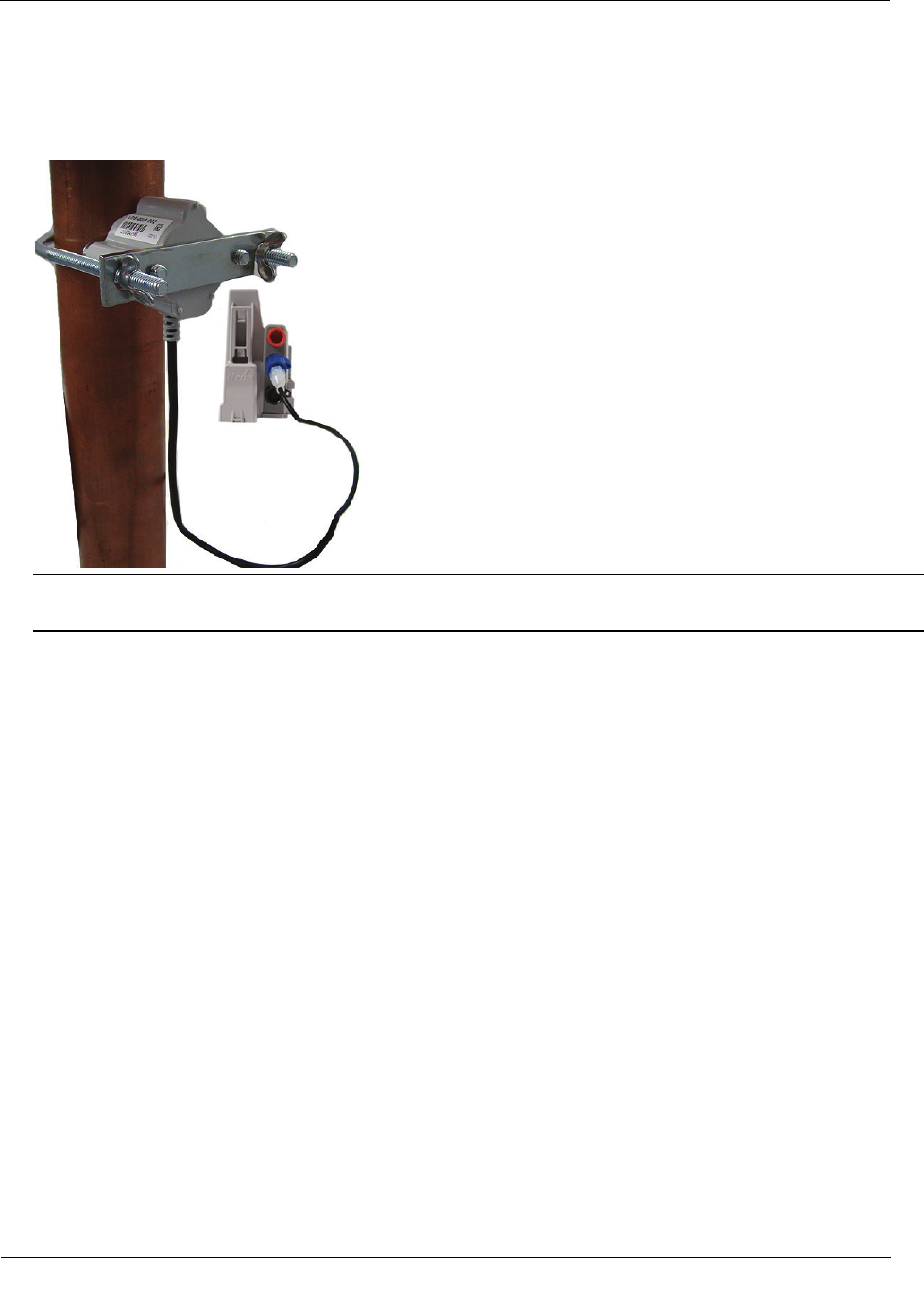
5. Insert the U-bolt around the pipe and into the holes in the plate/Leak Sensor assembly. Secure the U-bolt
with the wing nuts. Tighten the wing nuts until snug (to a minimum of 5-inch pounds) to prevent device
rotation on the pipe. After the second wing nut is tightened, check the Leak Sensor to verify the device is
snug. If the sensor moves, tighten the wing nuts until there is no movement.
Caution Do not tighten the Leak Sensor to more than 20 inch-pounds. Over-tightening could damage the
Leak Sensor housing and/or the pipe.

TDC
-0909-006 100W/100W+ and 100WP/100WP+ Datalogging Water ERT Module Installation Guide 32
Proprietary and Confidential
The optional 900 MHz remote mount antenna provides increased RF range coverage for the listed mobile
applications where the meters are located deep in a pit boxes.
This section provides antenna mounting instructions through a pit lid and the instructions to connect the
optional antenna to the ERT module.
Caution Only remote antenna ERT modules can be used with the remote antenna. See the following
table for 100W and 100WP remote antenna ERT models.
100W and 100WP ERT Module Models for use with Remote Antennas
100W and 100WP ERT Module Description
Itron Part Number
100W + encoder ERT module with optional remote antenna and register integral connectors ERW-1300-202
100W+ encoder ERT module with optional remote antenna and register integral connectors, ISM
ERW-1300-302
100W encoder ERT module with optional remote antenna, Leak Sensor, and register integral connectors ERW-1300-203
100W+ encoder ERT module with optional remote antenna, Leak Sensor, and register integral connectors, ISM ERW-1300-303
100W 5-ft. flying leads encoder ERT module with optional remote antenna integral connector
ERW-1300-205
100W+ 5-ft. flying leads encoder ERT module with optional remote antenna integral connector, ISM
ERW-1300-305
100W 5-ft. flying leads encoder ERT module with optional remote antenna and Leak Sensor connectors
ERW-1300-206
100W+ 5-ft. flying leads encoder ERT module with optional remote antenna and Leak Sensor connectors, ISM
ERW-1300-306
100W 20 in. flying leads encoder ERT module with optional remote antenna integral connector
ERW-1300-217
100W+ 20 in. flying leads encoder ERT module with optional remote antenna integral connector, ISM
ERW-1300-317
100WP 20 in. flying leads encoder ERT module with optional remote antenna and Leak Sensor integral connectors
ERW-1300-218
100WP+ 20 in. flying leads encoder ERT module with optional remote antenna and Leak Sensor integral connectors,
ISM
ERW-1300-318
100WP pulser ERT module with optional remote antenna and register integral connectors ERW-1300-208
100WP+ pulser ERT module with optional remote antenna and register integral connectors, ISM
ERW-1300-308
100WP pulser ERT module with optional remote antenna, Leak Sensor, and register integral connectors
ERW-1300-209
100WP+ pulser ERT module with optional remote antenna, Leak Sensor, and register integral connectors, ISM ERW-1300-309
100WP 5-ft. flying leads pulser ERT module with optional remote antenna and Leak Sensor integral connectors ERW-1300-212
100WP+ 5-ft. flying leads pulser ERT module with optional remote antenna and Leak Sensor integral connectors, ISM ERW-1300-312
100WP 20 in. flying leads pulser ERT module with optional remote antenna integral connector
ERW-1300-219
100WP +20 in. flying leads pulser ERT module with optional remote antenna integral connector, ISM ERW-1300-319
100WP 20 in. flying leads pulser ERT module with optional remote antenna and Leak Sensor integral connectors
ERW-1300-220
100WP + 20 in. flying leads pulser ERT module with optional remote antenna and Leak Sensor integral connectors,
ISM
ERW-1300-320
C
HAPTER
5
O
ptional Direct Connect Remote Antenna Installation
Optional Direct Connect Remote Antenna Installation
TDC
-0909-006 100W/100W+ and 100WP/100WP+ Datalogging Water ERT Module Installation Guide 33
Proprietary and Confidential
Industry Canada Conformity
This radio transmitter (IC:864D-100WC) has been approved by
Industry Canada to operate with the antenna types listed below
with the maximum permissible gain and required antenna
impedance for each antenna type indicated. Antenna types not
included in this list, having a gain greater than the maximum gain
indicated for that type, are strictly prohibited for use with this
device.
Le présent émetteur radio (IC: 864D-100WC) a été approuvé par
Industrie Canada pour fonctionner avec les types d'antenne
énumérés ci-dessous et ayant un gain admissible maximal et
l'impédance requise pour chaque type d'antenne. Les types
d'antenne non inclus dans cette liste, ou dont le gain est supérieur
au gain maximal indiqué, sont strictement interdits pour
l'exploitation de l'émetteur.
Specification
Part number
CFG-0900-003
Gain
2 dBi
Horizontal beamwidth Omni-directional
Impedance
50 ohms
Termination Proprietary
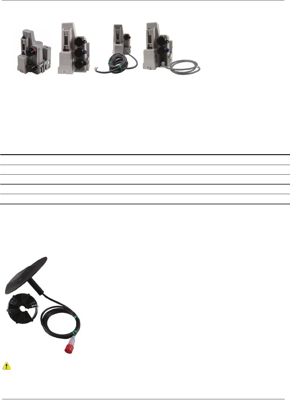
Installing the Remote Antenna
Metal lids on water pit boxes require a through-lid solution for optimal ERT module radio performance. The
remote antenna is designed to fit in a pit lid hole with a diameter of 3/4-inch and lid thicknesses from 1/4-inch
to 1-3/4-inch.
Caution Remove cable or twist ties from the antenna cable to prevent damage to the ERT
module or antenna.
Optional Direct Connect Remote Antenna Installation
TDC
-0909-006 100W/100W+ and 100WP/100WP+ Datalogging Water ERT Module Installation Guide 34
Proprietary and Confidential
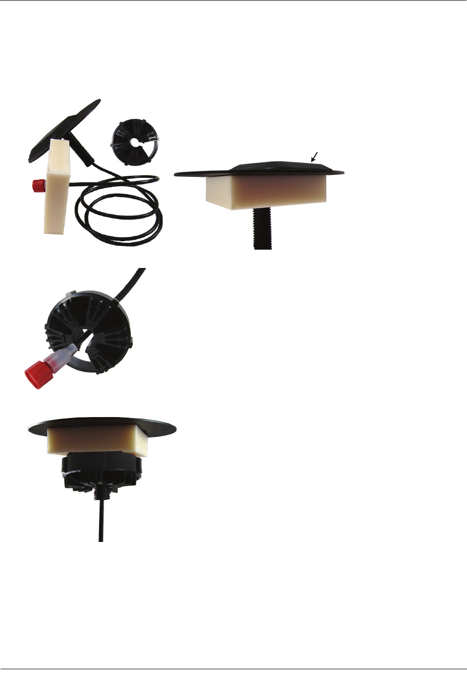
To install the remote antenna through a pit lid
1. Thread the remote antenna connector and cable through the pit lid hole. Verify the antenna's convex
surface is on the top of the pit lid. (These instructions show a simulated pit lid material.)
2. Insert the antenna connector through the rectangular opening in the threaded collar.
3. Turn the threaded collar until it is tight against bottom of the pit lid.
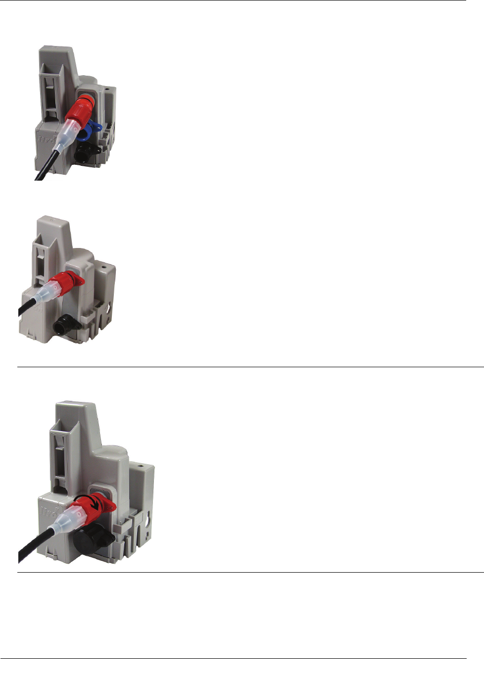
To connect the remote antenna to the ERT module
1. Align the connector pins with the top, red connector on the ERT module. The illustration shows a 3-port
ERT module connection.
Optional Direct Connect Remote Antenna Installation
TDC
-0909-006 100W/100W+ and 100WP/100WP+ Datalogging Water ERT Module Installation Guide 35
Proprietary and Confidential
2. Push in the antenna connector to complete the connection. The illustration shows a two-port ERT module
connection.
3. Turn the connector lock ring to the right to secure the connection.
Caution Turn the connector lock-ring only. Do not twist the completed connection. Twisting the
connection could damage the ERT module or antenna connector pins.
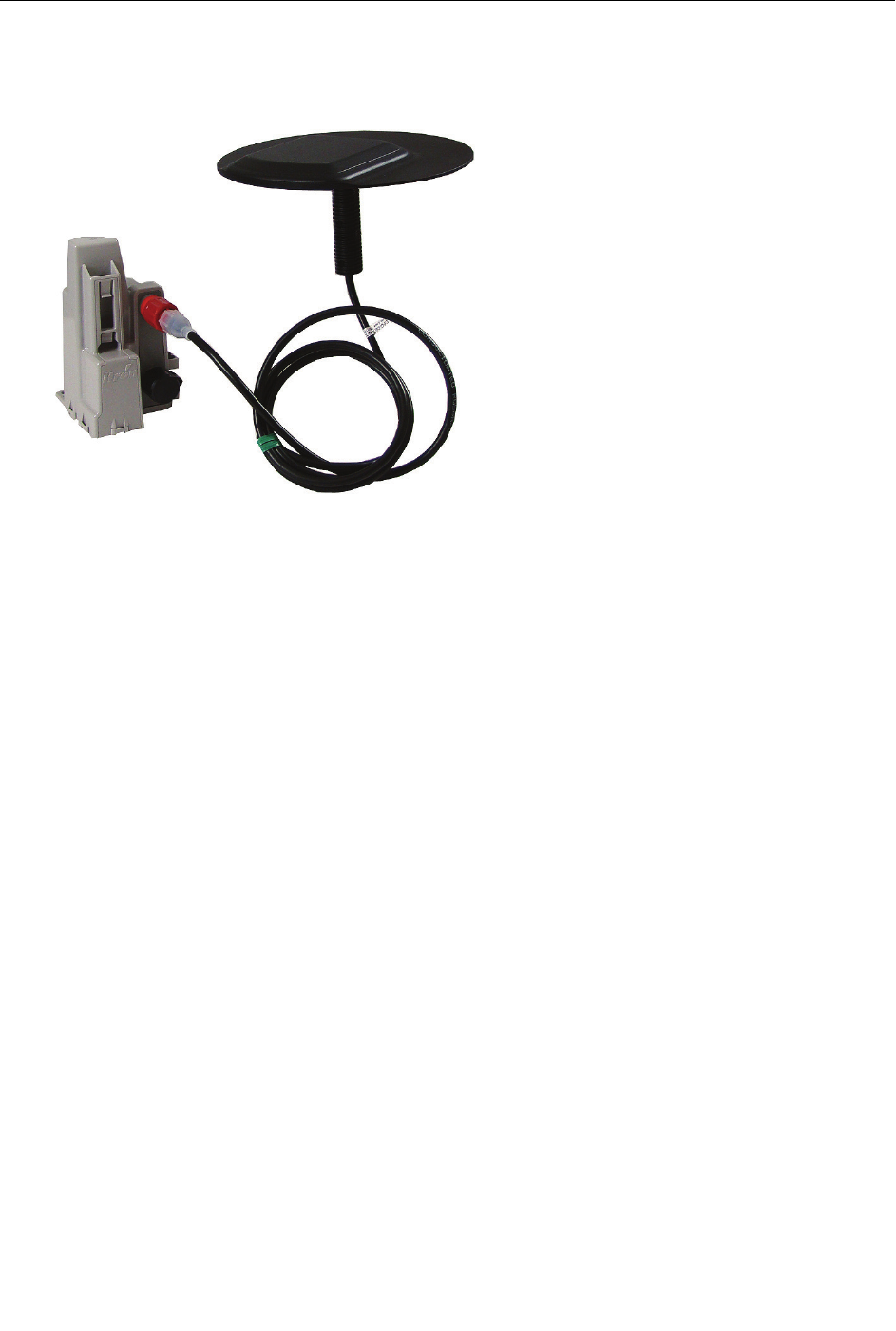
4. Follow the Rod Mount Installation on page 14 or Wall Mount Installation on page 17 instructions to
mount the ERT module.
Optional Direct Connect Remote Antenna Installation
TDC
-0909-006 100W/100W+ and 100WP/100WP+ Datalogging Water ERT Module Installation Guide 36
Proprietary and Confidential
Remote antenna installation is complete.