JVC KENWOOD 512000 Scanning Receiver User Manual 2
JVC KENWOOD Corporation Scanning Receiver Users Manual 2
Contents
- 1. Users Manual 1
- 2. Users Manual 2
- 3. Users Manual 3
- 4. Users Manual 4
Users Manual 2
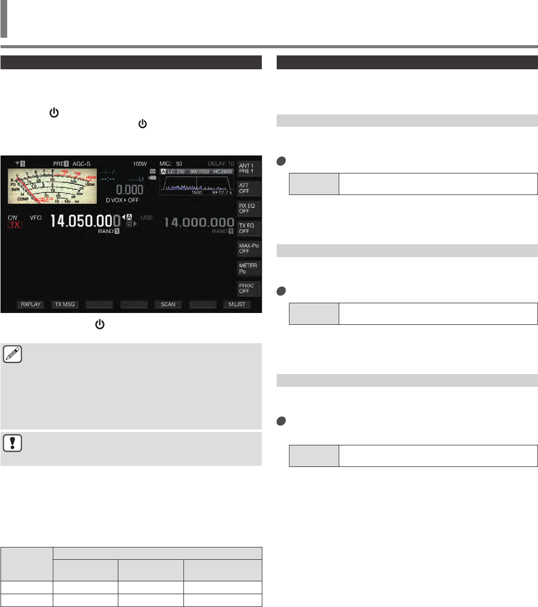
Turning ON/OFF the Power
Check to ensure that the connections are correct before turning on
the power of the regulated DC power supply.
1Press [ ].
When the power turns on, the [ ] LED lights up in green. The
message screen (“KENWOOD”, “HELLO”) is displayed,
followed by the frequency display.
.
2Press and hold [ ].
The power is turned off.
●The message screen “HELLO” can be changed. (Menu
[0-06] “Power-on Message”)
●When a voltage that exceeds approximately DC 18 V is
applied, the overvoltage protection circuit is activated
and the power is turned off automatically.
●When the temperature of this transceiver or the
surroundings is extremely low, it may take a while before
the screen reaches the normal level of brightness.
●To prevent damage of the internal data, do not turn off
the regulated DC power supply while leaving the power
of the TS-890S on.
Current Flow when Power is OFF
When the power of the external power supply is ON, a small
amount of electric current is flowing even when the power of this
transceiver is OFF. The amount of current that flows through when
power is OFF varies depending on whether this transceiver is
connected to a PC or connected for KNS operation.
PC
Connection
via USB
KNS Operation Setting
Off On (LAN)
LAN MODE On (Internet)
WAN MODE
No Approx. 4 mA Approx. 20 mA Approx. 150 mA
Yes Approx. 95 mA Approx. 110 mA Approx. 210 mA
•Refer to (1-4) for details on PC connection and (15-2) for
details on KNS operation.
Screen Display Settings
The background color of the screen, function key guide display
and font type for the frequency display can be changed.
Changing the Background Color
A background color for the screen can be chosen from the three
choices available.
Configure in Menu [0-00] “Color Display Pattern”
Setting
Value Type 1 (default)/ Type 2/ Type 3
Type 1: Black
Type 2: Blue
Type 3: Dark green
Changing the Type of Function Key Display
A function key display can be chosen from the three choices
available.
Configure in Menu [0-01] “Function Key Style”
Setting
Value Type 1 (default)/ Type 2/ Type 3
Type 1: Standard
Type 2: Gradation
Type 3: Illuminated
Changing the Frequency Display Font Type
A font type for the frequency display can be chosen from the five
choices available.
Configure in Menu [0-02] “Font Style (Frequency
Display)”
Setting
Value Font 1 (default)/ Font 2/ Font 3/ Font 4/ Font 5
Font 1: Type 1 fonts
Font 2: Type 2 fonts
Font 3: Type 1 italic fonts
Font 4: Type 2 italic fonts
Font 5: 7-segment fonts
BASIC OPERATIONS 4
4 BASIC OPERATIONS
4-1
Dimmer
Below are steps to adjust the brightness of the screen and LED.
Switching the Brightness Level
The preset brightness of the screen and LED can be adjusted
according to the surrounding conditions.
1Press [MENU].
2Press F [DIMMER].
Pressing F [DIMMER] each time switches the dimmer setting
in the following sequence: “DIMMER 1” → “DIMMER 2” →
“DIMMER 3” → “DIMMER 4”.
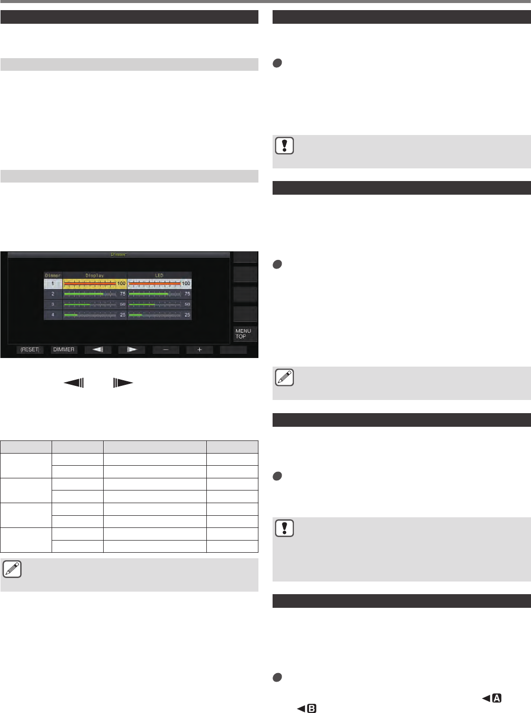
Adjusting the Dimmer Level
The preset values for “Dimmer 1”, “Dimmer 2”, “Dimmer 3” and
“Dimmer 4” can be configured to a different value for Display
(screen) and LED respectively.
1Press and hold F [DIMMER].
The Dimmer configuration screen appears.
.
2Press F2 [DIMMER] to select a dimmer preset.
3Press F3 [ ]/ F4 [ ] to select “Display” or
“LED”.
4Press F5 [–]/ F6 [+] or turn [MULTI/CH] to change the
setting value.
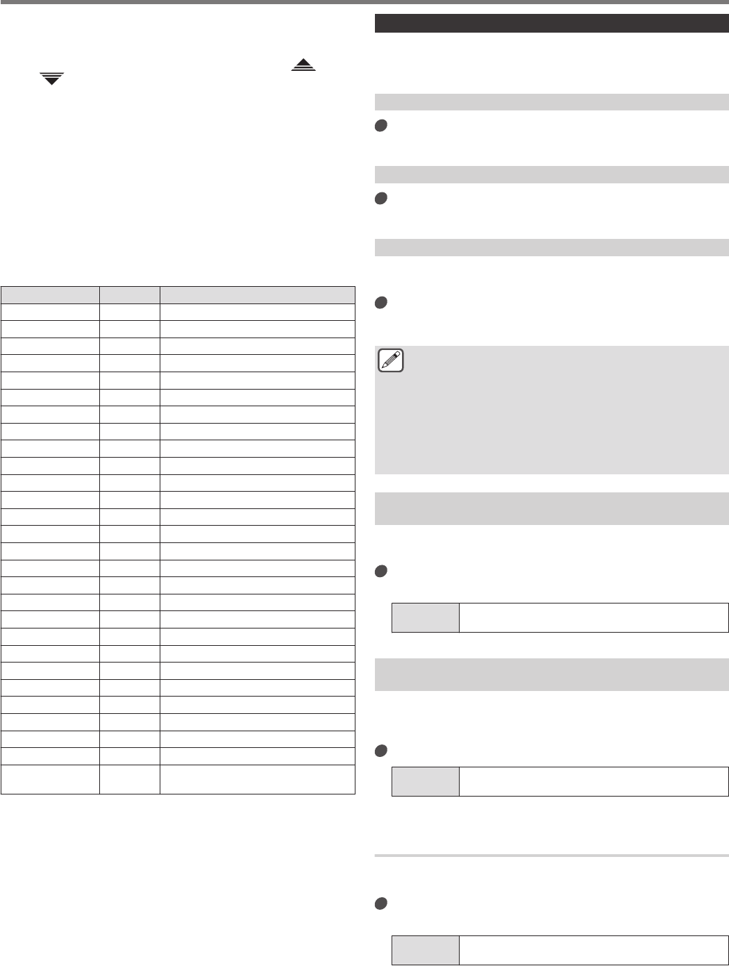
The setting values and default values are shown below.
Dimmer Display Setting Value Default
1Display 5 to 100 (5-step) 100
LED 5 to 100 (5-step) 100
2Display 5 to 100 (5-step) 75
LED 5 to 100 (5-step) 75
3Display 5 to 100 (5-step) 50
LED 5 to 100 (5-step) 50
4Display 0 to 100 (5-step) 25
LED 5 to 100 (5-step) 25
●Configuring the screen brightness to “0” and exiting the
menu turns all the lights off. Pressing [MENU] at this time
displays the screen with the dimmest level of brightness.
Adjusting AF Gain
Below are the steps to adjust the volume so that sound can be
heard from the speaker.
Turn the [AF] control.
Turning the control to the right raises the volume, while turning
to the left lowers it.
•If no sound is heard or if only a light noise-like sound is heard
even when the [AF] control is turned all the way to the right,
the squelch may be closed. Adjust the squelch level in this
case.
●The volume of the beep sound, sidetone and
announcement cannot be adjusted using the [AF]
control.
Adjusting RF Gain
Below are the steps to adjust the gain of the RF amplifier. Under
normal circumstances, turn the [RF] control all the way to the right.
To enhance clarity when there is external noise or interference by
other stations, turn the control slightly to the left to lower the gain
level.
Turn the [RF] control.
•Start by checking the peak scale of the S meter, followed by
turning the [RF] control in the anti-clockwise direction
without lowering the peak value of the S meter. Doing so
attenuates signals weaker than this level and eases
reception from the desired station.
•Depending on the type of antenna, gain level and band
condition, better effect may sometimes be achieved by
turning the [RF] control slightly to the left rather than all the
way to the right.
●In the FM mode, turning the [RF] control does not change
the gain level. Under normal circumstances, turn the
[RF] control all the way to the right.
Adjusting the Squelch Level
Below are steps to adjust the threshold level for squelch, a function
for eliminating noise that is heard when receiving a frequency with
no signal.
Turn the [SQL] control.
Configure the squelch level to the position where noise
disappears. When squelch opens upon receiving a signal, the
[BUSY/TX] LED lights up in green.
●The position of the [SQL] control at which noise
disappears varies according to the strength of the noise
and surrounding conditions such as temperature.
●The position of the control knob at which noise
disappears also varies depending on whether this
transceiver is in the FM mode or in other modes.
Selecting VFO A/ B
This transceiver is equipped with two VFOs, A and B. The two
VFOs operate independently of each other, and thus can be
configured to different frequencies and modes. Additionally, one
VFO can be configured to the TX frequency and the other to the
RX frequency.
Press [A/B].
Pressing [A/B] each time switches between “VFO A” and “VFO
B”. The currently selected VFO is indicated as << >> or
<< >>.
•Pressing and holding down [A/B] configures both “VFO A”
and “VFO B” to the same frequency and mode.
4 BASIC OPERATIONS
4-2
Selecting an Operating Band
Below are steps to select the frequency bandwidth to use. A
different frequency bandwidth can be selected for VFO A and VFO
B. By using the numeric keypad or [GENE] key, it is possible to call
up an amateur frequency between 1.8 MHz and 50/70 (E type) MHz
or a general band frequency at one touch.
•This transceiver comes with a band memory feature that is able
to store up to 5 pairs of frequencies and modes (3 pairs in the
default setting) that were used most recently for each band.
Press [1 (1.8)] to [0 (50)] or [GENE].
•Pressing one of the above keys saves the current VFO
frequency and mode and calls up the next memory band at
the same time. Pressing the key each time switches to the
next band memory in sequence from band memory 1 to band
memory 5.
•Frequencies that are out of the range of the band memory
will not be stored.
•The default values for each of the band memories are as
follows.
K Type
Band/
Frequency
(MHz)/
Mode
Default Setting (MHz)/Mode
Band
Memory
1
Band
Memory
2
Band
Memory
3
Band
Memory
4
Band
Memory
5
1.8 MHz/
1.62 to 2 1.8/
CW 1.81/
CW 1.82/
CW 1.83/
CW 1.84/
CW
3.5 MHz/
3 to 4 3.5/
LSB 3.6/
LSB 3.7/
LSB 3.8/
LSB 3.9/
LSB
7 MHz/
6.5 to 7.5 7.0/
LSB 7.05/
LSB 7.1/
LSB 7.15/
LSB 7.2/
LSB
10 MHz/
10 to 10.5 10.1/
CW 10.11/
CW 10.12/
CW 10.13/
CW 10.14/
CW
14 MHz/
13.5 to
14.5
14.0/
USB 14.1/
USB 14.15/
USB 14.20/
USB 14.25/
USB
18 MHz/
18 to 19 18.068/
USB 18.1/
USB 18.11/
USB 18.15/
USB 18.16/
USB
21 MHz/
20.5 to
21.5
21.0/
USB 21.1/
USB 21.15/
USB 21.2/
USB 21.3/
USB
24 MHz/
24 to 25 24.89/
USB 24.92/
USB 24.94/
USB 24.96/
USB 24.98/
USB
28 MHz/
27.5 to 30 28/
USB 28.3/
USB 28.5/
USB 29/
FM 29.3/
FM
50 MHz/
50 to 54 50/
USB 50.125/
USB 50.2/
USB 51/
FM 52/
FM
General/
0.030 to 60 0.1357/
CW 0.472/
CW 1/
AM 5.3305/
USB 5.4035/
USB
E Type
Band/
Frequency
(MHz)
Default Setting (MHz)/Mode
Band
Memory
1
Band
Memory
2
Band
Memory
3
Band
Memory
4
Band
Memory
5
1.8 MHz/
1.62 to 2 1.83/
CW 1.84/
CW 1.85/
CW 1.81/
CW 1.82/
CW
3.5 MHz/
3 to 4 3.5/
LSB 3.55/
LSB 3.6/
LSB 3.65/
LSB 3.7/
LSB
7 MHz/
6.5 to 7.5 7.0/
LSB 7.05/
LSB 7.1/
LSB 7.15/
LSB 7.2/
LSB
10 MHz/
10 to 10.5 10.1/
CW 10.11/
CW 10.12/
CW 10.13/
CW 10.14/
CW
14 MHz/
13.5 to
14.5
14.0/
USB 14.1/
USB 14.15/
USB 14.20/
USB 14.25/
USB
18 MHz/
18 to 19 18.068/
USB 18.1/
USB 18.11/
USB 18.15/
USB 18.16/
USB
21 MHz/
20.5 to
21.5 21.0/ USB 21.1/ USB 21.15/
USB 21.2/ USB 21.3/ USB
24 MHz/ 24
to 25 24.89/
USB 24.92/
USB 24.94/
USB 24.96/
USB 24.98/
USB
28 MHz/
27.5 to 30 28/
USB 28.3/
USB 28.5/
USB 29/
FM 29.3/
FM
50 MHz/
50 to 54 50/
USB 50.15/
USB 50.2/
USB 51/
FM 52/
FM
General/
0.030 to
74.8
70.1/
USB 0.1357/
CW 0.472/
CW 0.999/
AM 5.2585/
USB
●When the number of band memories is reduced, the
change will be applied when the band memory is
switched.
Changing the Number of Band Memories
The number of band memories can be changed.
Configure in Menu [3-11] “Number of Band
Memories”
Setting
Value 1/ 3 (default)/ 5
BASIC OPERATIONS 4
4-3
Selecting an Operating Mode
Below are steps to select an operating mode. It is also possible to
configure the operating mode to DATA mode for data
communication.
SSB (LSB-USB) Mode
Press [LSB/USB].
Pressing [LSB/USB] each time switches between “LSB” and
“USB”.
.
LSB USB
CW/ CW-R Mode
Press [CW/ CW-R].
Pressing [CW/ CW-R] each time switches between “CW” and
“CW-R”.
.
CW CW-R
FSK/ FSK-R/ PSK/ PSK-R Mode
Press [FSK/PSK].
Pressing [FSK/PSK] each time switches between “FSK” and
“PSK”.
•Pressing and holding down [FSK/PSK] each time in the
respective modes switches the mode to FSK-R and PSK-R.
.
FSK
FSK-R
PSK
PSK-R
FM/ AM Mode
Press [FM/AM].
Pressing [FM/AM] each time switches between “FM” and “AM”.
•While in the FM mode, pressing and holding down [FM/AM]
each time switches between “FM” and “FMN” (FM Narrow).
.
FM
FMN
AM
●The mode and DATA mode settings are stored in the
band memory.
●FM narrow and normal settings are stored in each of the
following bandwidths: HF, 50 MHz and 70 MHz.
DATA Mode
This is a mode for data communication by connecting an external
device.
1Press the mode key to configure to FM, AM or SSB
(LSB/USB) mode.
2Press [DATA].
Pressing [DATA] each time switches between “DATA OFF”
and “DATA ON”.
DATA OFF DATA ON
During LSB Mode LSB LSB-D
During USB Mode USB USB-D
During FM Mode FM FM-D
During FMN Mode FMN FMN-D
During AM Mode AM AM-D
●Turn OFF the speech processor before performing data
communication.
●Settings such as the method of standby and muting
audio input path that is not used during transmission can
be configured for each of the DATA OFF and DATA ON
statuses.
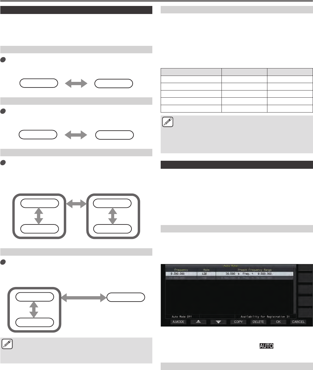
Auto Mode
By configuring the auto mode frequency point and the
corresponding operating mode in advance, the operating mode
will switch automatically when the frequency exceeds the auto
mode frequency point after it has been changed.
•Auto mode is a convenient function that allows automatic
switching of the operating mode according to the band plan.
•Up to 32 points can be configured for the auto mode frequency.
Turning ON/OFF Auto Mode
1Press [MENU].
2Press F [AUTO MODE] to display the Auto Mode
screen.
.
3Pressing F1 [A.MODE] each time switches the Auto
Mode to ON or OFF.
When the Auto Mode is turned ON, << >> is displayed.
This display disappears when Auto Mode is turned OFF.
Configuring Auto Mode Frequency Points
1Display the Auto Mode screen.
2Turn the Tuning control to select a frequency point.
Align the frequency of the selected band with the frequency to
register.
3Press the Mode key or press and hold down the key
to switch to the mode to which the band is to be
registered.
4 BASIC OPERATIONS
4-4
4Press F4 [COPY] to copy the frequency and mode.
•The frequency and mode of the selected band is imported
into the list as a new classification.
•To delete a registered classification, press F2 [ ]/ F3
[ ] or turn the [MULTI/CH] control to select the row to
delete, followed by pressing F5 [DELETE] to delete the row.
Doing so shifts up the classifications after the deleted row in
the list.
5Repeat the steps from 2 to 5 to configure the
frequency and mode for all the points.
6Press F6 [OK].
•When the Auto Mode is turned ON, the mode that is assigned
to the respective channels will be automatically selected. In the
SSB mode, LSB mode will be selected for frequencies below
10.1 MHz, and USB mode will be selected for frequencies that
are 10.1 MHz or higher.
•The table below shows an example when auto mode frequency
is configured to the HF/50/70 MHz band.
Frequency Mode Preset Frequency Range
1.620 MHz AM 30 kHz≦f<1.62 MHz
2.000 MHz CW 1.62 MHz≦f<2.0 MHz
3.500 MHz LSB 2.0 MHz≦f<3.5 MHz
3.525 MHz CW 3.5 MHz≦f<3.535 MHz
10.100 MHz LSB 3.535 MHz≦f<10.1 MHz
10.150 MHz CW 10.1 MHz≦f<10.15 MHz
14.000 MHz USB 10.15 MHz≦f<14.0 MHz
14.070 MHz CW-R 14.0 MHz≦f<14.07 MHz
14.112 MHz FSK 14.07 MHz≦f<14.112 MHz
18.068 MHz USB 14.112 MHz≦f<18.068 MHz
18.110 MHz CW 18.068 MHz≦f<18.11 MHz
21.000 MHz USB 18.11 MHz≦f<21.0 MHz
21.070 MHz CW 21.0 MHz≦f<21.07 MHz
21.125 MHz FSK-R 21.07 MHz≦f<21.125 MHz
21.150 MHz CW 21.125 MHz≦f<21.15 MHz
24.890 MHz USB 21.15 MHz≦f<24.89 MHz
24.930 MHz CW 24.89 MHz≦f<24.93 MHz
28.000 MHz USB 24.93 MHz≦f<28.0 MHz
28.070 MHz CW 28.0 MHz≦f<28.07 MHz
28.150 MHz FSK 28.07 MHz≦f<28.15 MHz
28.200 MHz CW 28.15 MHz≦f<28.2 MHz
29.000 MHz USB 28.2 MHz≦f<29.0 MHz
30.000 MHz
FM-DATA
29.0 MHz≦f<30.0 MHz
50.000 MHz USB 30.0 MHz≦f<50.0 MHz
50.100 MHz CW 50.0 MHz≦f<50.1 MHz
51.000 MHz USB 50.1 MHz≦f<51.0 MHz
52.000 MHz FM 51.0 MHz≦f<52.0 MHz
– USB
52.0 MHz≦f<60.0 MHz (K type)
52.0 MHz≦f<74.8 MHz (E type)
Adjustment of Frequencies
The steps to adjust the TX and RX frequencies are described
below.
Adjustment Using the Tuning Control
Turn the Tuning control to increase or decrease the
frequency.
Adjustment Using the Microphone Key
Press the [UP] or [DWN] key on the microphone to
increase or decrease the frequency.
FINE Tuning
The step frequency of the Tuning control can be configured to one-
tenth of the step size. Doing so allows fine-tuning of the frequency.
Press [FINE].
Pressing [FINE] each time toggles FINE tuning between ON
and OFF.
●When fine tuning is set to OFF, the 1 Hz digit frequency
display will be grayed out. When in the FM or AM mode,
both the 10 Hz and 1 Hz digits are grayed out. Setting
fine tuning to ON turns off the gray-out display and shows
the frequency in full up to the 1 Hz digit.
●Depending on the operating frequency, the 1 Hz digit
display may not gray out on the operating frequency
display of the transverter even when fine tuning is set to
OFF.
Configuring the Number of Steps per Revolution of
the Tuning Control
The number of steps per revolution of the Tuning control can be
changed.
Configure in Menu [3-07] “Tuning Control: Number
of Steps per Revolution”
Setting
Value 250/ 500/ 1000 (default) [Step]
Configuring the Fast Forward Rate of the Tuning
Control
This function enables the speed of frequency change to increase
by 2 to 10 times with respect to the speed of turning when the
Tuning control is turned at a fast speed.
Configure in Menu [3-08] “Tuning Speed Control”
Setting
Value Off (default)/ 2 to 10 (1 step)
Configuring the Sensitivity for Starting the Fast
Forward Operation
Configuring this to a larger value increases the sensitivity for
starting the fast forward operation.
Configure in Menu [3-09] “Tuning Speed Control
Sensitivity”
Setting
Value 1 to 5 (default) to 10 (1 step)
BASIC OPERATIONS 4
4-5
Frequency Adjustment Using the [MULTI/CH] Control
Turning the [MULTI/CH] control enables the frequency to be
changed quickly. The frequency increases or decreases in
increments based on the configured step size.
Turn the [MULTI/CH] control to increase or
decrease the frequency.
The default frequency per step is 1 kHz in the SSB mode,
0.5 kHz in the CW/ FSK/ PSK mode, 5 kHz in the AM mode and
10 kHz in the FM mode.
Rounding the Frequency
When the frequency is adjusted by turning the [MULTI/CH]
control, the new frequency is automatically rounded to the integer
multiple of the step size. Rounding of the frequency can also be
disabled.
Configure in Menu [3-00] “Frequency Rounding Off
(Multi/Channel Control)”
Setting
Value Off/ On (default)
Configuring the Frequency Step Size of the
[MULTI/CH] Control
The frequency per step when the [MULTI/CH] control is turned
can be configured or changed to a different value for each mode.
SSB Mode
Configure in Menu [3-01] “SSB Mode Frequency
Step Size (Multi/Channel Control)”
Setting
Value 0.5/ 1 (default)/ 2.5/ 5/ 10 [kHz]
CW/ FSK/ PSK Mode
Configure in Menu [3-02] “CW/FSK/PSK Mode
Frequency Step Size (Multi/Channel Control)”
Setting
Value 0.5 (default)/ 1/ 2.5/ 5/ 10 [kHz]
FM Mode
Configure in Menu [3-03] “FM Mode Frequency Step
Size (Multi/Channel Control)”
Setting
Value 5/ 6.25/ 10 (default)/ 12.5/ 15/ 20/ 25/ 30/ 50/ 100 [kHz]
AM Mode
Configure in Menu [3-04] “AM Mode Frequency Step
Size (Multi/Channel Control)”
Setting
Value 5 (default)/ 6.25/ 10/ 12.5/ 15/ 20/ 25/ 30/ 50/ 100 [kHz]
Switching the AM Broadcast Frequency in 9 kHz Steps
In the BC band (medium frequency band) from 522 kHz to
1710 kHz and LF band (long frequency band) from 153 kHz to
279 kHz, the RX frequency can be adjusted in steps of 9 kHz by
turning the [MULTI/CH] control.
Configure in Menu [3-05] “9 kHz Step in AM
Broadcast Band (Multi/Channel Control)”
Setting
Value Off (K type: default)/ On (E type: default)
Adjusting Frequency in MHz Steps
The frequency can be adjusted in units of MHz.
1Press [MHz].
Pressing [MHz] each time toggles the MHz step function
between ON and OFF.
When the function is turned ON, << >> lights up.
2Turn the [MULTI/CH] control while the function is
turned ON.
The frequency increases or decreases according to the MHz
frequency step configured in Menu [3-06].
Configuring the Frequency Step Size in MHz
Configure in Menu [3-06] “MHz Step”
Setting
Value 100/ 500/ 1000 (default) [kHz]
Direct Input of Frequency Value
If the desired frequency is far apart from the current frequency
value, the fastest way is to input the frequency value directly using
the numeric keypad.
1Press [ENT].
A screen to input the frequency for the operable band appears
with all the frequency digits displayed as “-”.
.
2Key in a frequency value using the numeric keypad.
•“-” changes into a numeric value when a numeric key is pressed
and a value can be input starting from the highest-order digit.
•To enter 1.82 MHz, press [0/50], [1/1.8], [8/24] followed by
[2/3.5], and press [ENT] when input is complete.
•To enter a frequency lower than 6 MHz for K type
transceivers, start by keying in a “0”.
•To enter a frequency lower than 8 MHz for E type
transceivers, start by keying in a “0”.
•Pressing [CLR] halfway through the input process clears the
input and restores the VFO frequency display before the input.
.
•During fine tuning, a frequency up to 59.99999 MHz can be input
(input of 60 MHz is not allowed).
•Pressing [ENT] halfway through the input process fills the
remaining digits with “0” and completes the input.
•When a frequency value out of the TX and RX range is input, an
alarm tone is output and the input value is automatically cleared.
•If the first input value is between 0 and 5, input starts from the
10 MHz digit. If the first input value is between 6 and 9, input
starts from the 1 MHz digit.
•“0” that is entered up to the 10 Hz digit will not appear as “0” in the display.
•Inputting a frequency value automatically switches RIT and XIT
to OFF but does not clear the offset frequency.
•When fine tuning is OFF, the smallest digit for input is the 10 Hz digit
in modes other than AM and FM, and 100 Hz in the AM and FM mode.
•When in the auto mode, the mode switches automatically after
input of frequency is complete.
4 BASIC OPERATIONS
4-6
Frequency Input History
The latest 10 frequency values that were input using the numeric
keypad are stored in the transceiver. To use the same frequency
value, it is possible to retrieve it from the history.
1Press [ENT] to enable input of a frequency value.
“-” is displayed for all digits of the frequency value.
2Turn the [MULTI/CH] control to display the history.
•Frequency values that were previously entered and the
record number (E0 to E9) are displayed. The first frequency
value shown is the most recent input.
•Turning the control to the right jumps to the subsequent
record numbers in ascending order. The larger the record
number, the older the record.
.
3Press [ENT] to configure the selected frequency to
VFO.
●When 10 frequency values have been registered, the
oldest input in the history will be deleted when another
frequency value is registered.
Frequency Lock
The frequency lock function disables operation of specific keys or
control knobs to prevent the frequency from being altered
accidentally due to erroneous operation of the key or control
knobs.
Press [LOCK] to lock the frequency value.
The [LOCK] LED lights up in orange.
The following operations are disabled when frequency lock is
turned on.
•Frequency tuning
•Change of memory channel
•Change of quick memory channel
•Direct input of frequency value
•Registration of memory channel
•Starting program scan or VFO scan
•Starting memory scan or quick memory scan
•Switching between the VFO and memory channel modes
•Frequency band selection
•Memory shift
•Configuring the frequencies for VFO A and VFO B to the
same value
•Switching between VFO A and VFO B
•Mode selection
•Switching to FINE tuning
•CW auto tune
•Quick memory channel mode switch
•Registration of quick memory channel
•Touchscreen tuning
●When “Tuning Control Lock” is selected in Menu [3-10],
only the Tuning control will be locked.
Lock Target
This function allows the selection of a control knob to be locked.
Configure in Menu [3-10] “Lock Function”
Setting
Value Frequency Lock (default)/ Tuning Control Lock
Frequency Lock: Locks both Tuning and [MULTI/CH]
controls.
Tuning Control Lock: Locks only the Tuning control.
Transmission
Audio Transmission
1Press and hold the [PTT] key on the microphone or
press the [SEND] key.
The transmitting status is activated and the [BUSY/TX] LED
lights up in red.
2Speak into the microphone in the normal tone and
loudness.
3Release the [PTT] key on the microphone or press the
[SEND] key.
Doing so restores the receiving status.
CW Transmission
Performing the following steps when a key or paddle is connected
enables transmission in the CW mode.
1Press [CW/ CW-R] to select CW mode.
2Press [VOX] to enable break-in.
3Operate the keyer or paddle.
Adjusting Microphone Gain
Microphone gain can be adjusted in the SSB or AM mode as
follows while referring to the ALC meter display.
1Press and hold the [PTT] key on the microphone or
press the [SEND] key.
•The transmitting status is activated and the [BUSY/TX] LED
lights up in red.
2Speak into the microphone in the normal tone and
loudness.
3Turn the [MIC/PITCH] control to adjust the microphone
gain level.
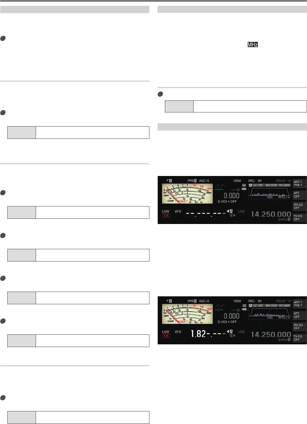
Microphone gain is displayed as “MIC:nnn” at the top of the
screen. [nnn: 0 to 100]
.
When in the SSB mode
Turn the [MIC/PITCH] control while speaking into the
microphone. The ALC meter fluctuates according to the
volume level. Ensure that the maximum level does not exceed
the ALC zone during the adjustment.
When in the AM mode
Turn the [MIC/PITCH] control while speaking into the
microphone. Adjust in such a way that the PWR meter
fluctuates slightly according to the volume level.
4Release the [PTT] key on the microphone or press the
[SEND] key.
Depending on the squelch level setting, the [BUSY/TX] LED
may light up in green or go off.
BASIC OPERATIONS 4
4-7
●Speak into the microphone in the normal tone and
loudness. Make sure that your mouth is not too close to
the microphone and do not speak too loudly. Doing so
may increase the extent of distortion, thus causing
audibility to deteriorate at the receiving end.
●To use a speech processor, refer to “Speech
Processor”.
●Note that the output level tend to be larger when a
microphone with a built-in AF amplifier is used.
●Microphone gain in the FM mode can be configured in
Advanced Menu [10] “Microphone Gain (FM Mode)”.
Adjusting TX Output Power
Maintain a TX output power level that is as low as possible while
ensuring that communication can be carried out smoothly. Doing
so reduces the likelihood of interference with other stations.
The TX output power level can also be adjusted while transmission
is in progress.
Turn the [POWER] control to adjust the TX output
power.
Turning the [POWER] control to the right increases the output
level, while turning it to the left reduces the output level. The
selectable range varies with the band and mode in use as
follows.
Other than AM AM
HF Band 5 to 100 [W] 5 to 25 [W]
50 MHz Band 5 to 100 [W] 5 to 25 [W]
70 MHz Band (E type) 5 to 50 [W] 5 to 12.5 [W]
●Output is displayed in a step size of 1 W. An output of
12.5 W will be shown as “12 W”.
Fine Adjustment of TX Output Power
It is possible to alter the step size when the [POWER] control is
turned.
Configure in Menu [6-04] “Transmit Power Step
Size”
Setting
Value 1 [W]/ 5 (default) [W]
1[W]: Adjusts the TX output level in a step size of 1 W.
5[W]: Adjusts the TX output level in a step size of 5 W (e.g., 5,
10, 15...).
TX Output Power Limiter
The TX output power limiter can be used to limit the TX output
power. This is a function to prevent the TX output power level from
exceeding the preconfigured level for each band when the
[POWER] control is turned. It can also be used to limit TX output
power only in the DATA mode with a specific band.
Turning ON/OFF TX Output Power Limiter
Press F [MAX-Po].
Pressing F [MAX-Po] each time toggles the TX output power
limiter function between ON and OFF.
•When the TX output power limiter is turned ON, pressing F
[MAX-Po] displays the confirmation screen for turning off the
TX output power limiter.
.
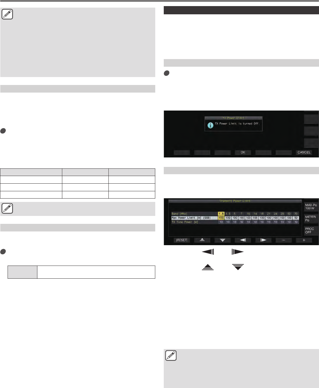
Configuring the TX Output Power Limiter
1Press and hold F [MAX-Po] to display the TX output
power limiter screen.
.
2Press F4 [ ]/ F5 [ ] to select a frequency
band.
3Press F2 [ ]/ F3 [ ] to select the TX output
power to limit.
Select the TX output power item to limit as follows.
Max Power Limit: For configuring the TX output power limit
during transmission.
•The TX output power limit can be configured separately for
the SSB, CW, FSK/PSK, FM/AM and DATA modes.
TX Tune Power: For configuring the TX output power limit
during TX tuning.
4Press F6 [–] / F7 [+] or turn the [MULTI/CH] control
to select a limit value for TX output power.
•To restore the default setting, press and hold F1
[(RESET)].
●A different TX output power limit cannot be configured
for the antenna connectors (antenna 1/2).
●If Advanced Menu [06] “TX Power Down with Transverter
Enabled” is configured to “On”, the F [MAX-Po] and watt
display at the right edge of the screen will disappear
when the transverter or drive output is turned ON.
4 BASIC OPERATIONS
4-8
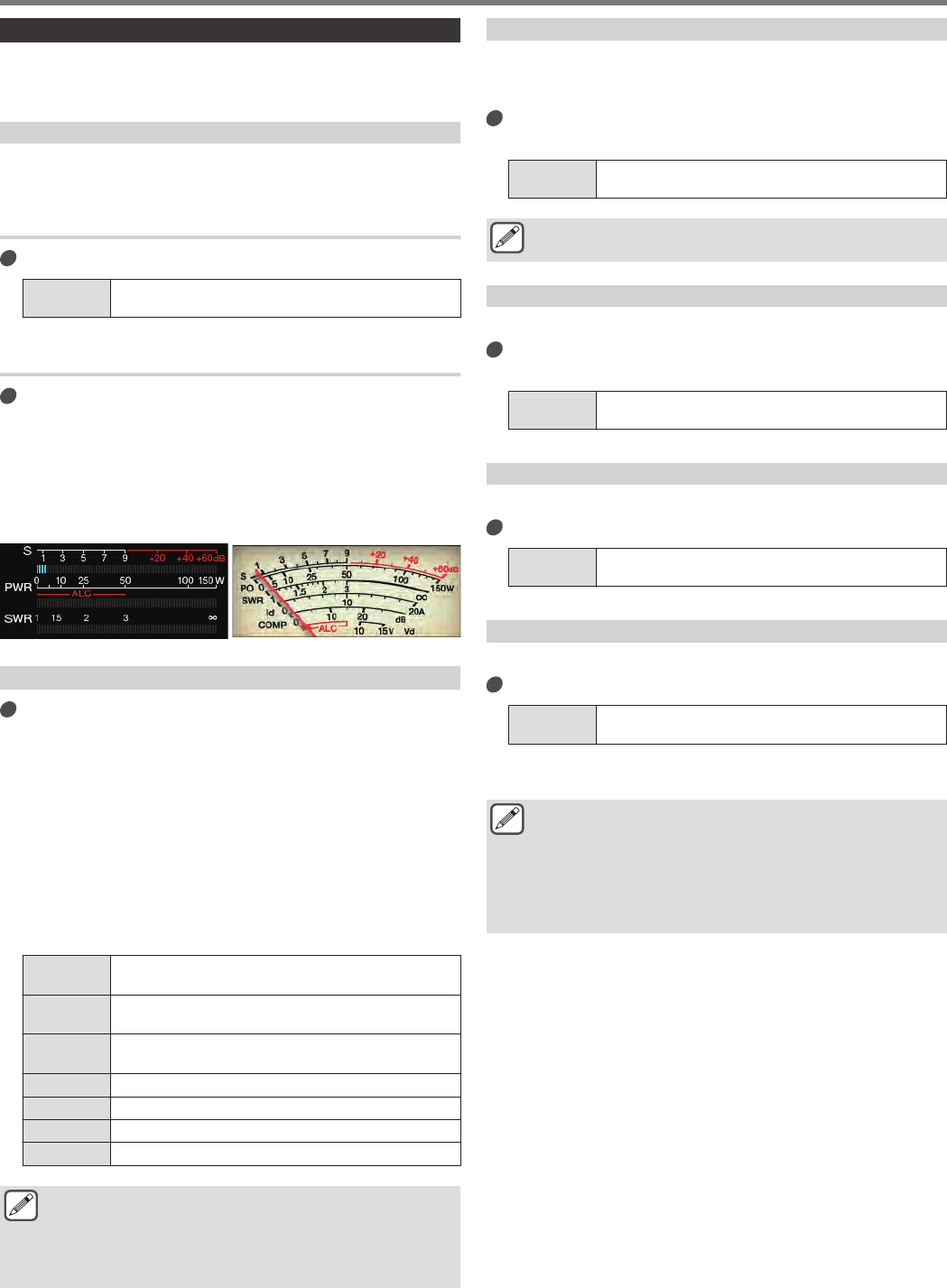
Meter
The meter displays the measured reading of the S meter during
reception and that of the selected meter during transmission.
Changing the Meter Type
A digital meter and two types of analog meters are available for
selection.
Changing the Meter Type from the Menu
Configure in Menu [0-09] “Meter Display Pattern”
Setting
Value Digital/ Analog (White) (default)/ Analog (Black)
Changing the Meter Type via Touchscreen Operation
Touch the meter display area while an analog or
digital meter is displayed
Touching the screen each time switches the meter in the
following sequence: “Digital” → “Analog (White)” → “Analog
(Black)”.
•When in the compressed mode, touching the meter will not
change the display.
.
Analog MeterDigital Meter
Switching between TX Meters
Press F [METER].
Press F [METER] each time switches the display as follows
according to the meter type.
Analog meter display when the TX meter (digital) is OFF:
“Po” → “SWR” → “Id” → “COMP”* → “ALC” → “Vd” →…
Display at the bottom of the TX meter (digital) when the
TX meter (digital) is ON:
“SWR” → “Id” → “COMP”* → “Vd” → “TEMP” →…
The last line of the display in the digital meter display
mode:
“SWR” → “Id” → “COMP”* → “Vd” → “TEMP” →…
When a mini digital meter is displayed:
“Po” → “SWR” → “Id” → “COMP”* → “ALC” → “Vd” → “TEMP” →…
Po Indicates the TX output power. (Output power at the
peak)
SWR Indicates the standing wave ratio which reflects the
matching status of the antenna.
COMP Indicates the amount of TX audio amplitude that is
compressed by the speech processor.
ALC Indicates the ALC level.
ld Indicates the drain current of the final FET.
Vd Indicates the voltage of the final FET.
TEMP Indicates the temperature of the internal circuit.
●An external meter can also be used to display the signal
level by connecting an analog meter to the METER
terminal on the rear panel.
●*: COMP meter can only be selected when the speech
processor is ON.
FM Mode S-meter Sensitivity
The default deflection type in the FM mode is the same as that in
the other modes. Selecting “High” switches the transceiver to the
same deflection type (high sensitivity) as our conventional models.
Configure in Menu [0-07] “FM Mode S-Meter
Sensitivity”
Setting
Value Normal (default)/ High
●This function is available when Menu [0-11] “S-Meter
Scale” is configured to “Type 1”.
Analog Meter Response
Configure the response speed of the analog meter indicator.
Configure in Menu [0-08] “Meter Response Speed
(Analog)”
Setting
Value 1 to 3 (default) to 4 (1 step)
Meter with Peak Hold
Display the peak hold of the digital meter.
Configure in Menu [0-10] “Meter Display Peak Hold”
Setting
Value Off/ On (default)
S Meter Scale
Switch the type of deflection for the S meter.
Configure in Menu [0-11] “S-Meter Scale”
Setting
Value Type 1 (default)/ Type 2
Type 1: Same scale as our HF products.
Type 2: Initial deflection is more sensitive compared to Type 1.
●Additional notes for “Type 2”
•The S meter indicator will appear deflected at all times
when there is external noise.
•The movement may not be smooth as it is a pseudo
representation of the S meter deflection.
•Narrowing the RF gain may disrupt the continuity from
S0 to S4.
BASIC OPERATIONS 4
4-9
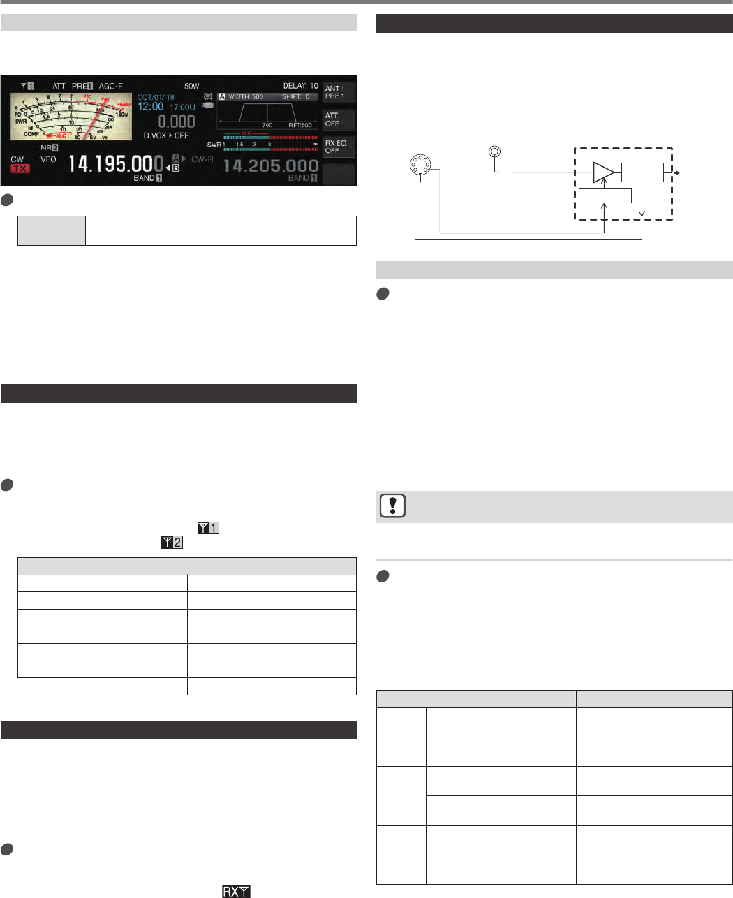
TX Meter (Digital)
In addition to the analog meter display, a two-tiered digital meter
can also be displayed at the same time.
.
Configure in Menu [0-12] “TX Digital Meter”
Setting
Value Off (default)/ On
•The TX meter (digital) only appears in the analog meter
display mode.
•The TX meter (digital) is displayed in a two-tiered bar format.
ALC is shown at the upper level, while the display at the lower
level varies according to the setting of the F [METER] digital
meter.
•During transmission, the analog meter always displays the
TX output power.
Switching the Antenna
Switch the antenna that is connected to the antenna connector.
The ANT 1/2, RX ANT and DRV settings are automatically stored
in the antenna band memory. When the same band is selected
subsequently, the same antenna will be selected automatically.
Press and hold F [ANT/PRE].
Pressing and holding F [ANT/PRE] switches the option
between “ANT 1” and “ANT 2”.
•When “ANT 1” is selected, << >> is displayed. When
“ANT 2” is selected, << >> is displayed.
Selectable Antenna Frequency Range (MHz)
0.03 to 0.522 10.5 to 14.5
0.522 to 2.5 14.5 to 18.5
2.5 to 4.1 18.5 to 21.5
4.1 to 6.9 21.5 to 25.5
6.9 to 7.5 25.5 to 30.0
7.5 to 10.5 30.0 to 60.0
60.0 to 74.8 (E type)
RX Antenna
Select an RX antenna.
To use an RX antenna such as an HF low-band Beverage antenna
or a directional loop antenna, connect it to the RX IN terminal on
the rear panel. The input impedance is 50 Ω. A self-made or
commercially available BPF or trap filter can also be inserted
between the RX IN and RX OUT terminals.
Press [RX ANT].
Pressing [RX ANT] each time enables or disables the RX
antenna of the selected band.
When the RX antenna is enabled, << >> is displayed on
the screen.
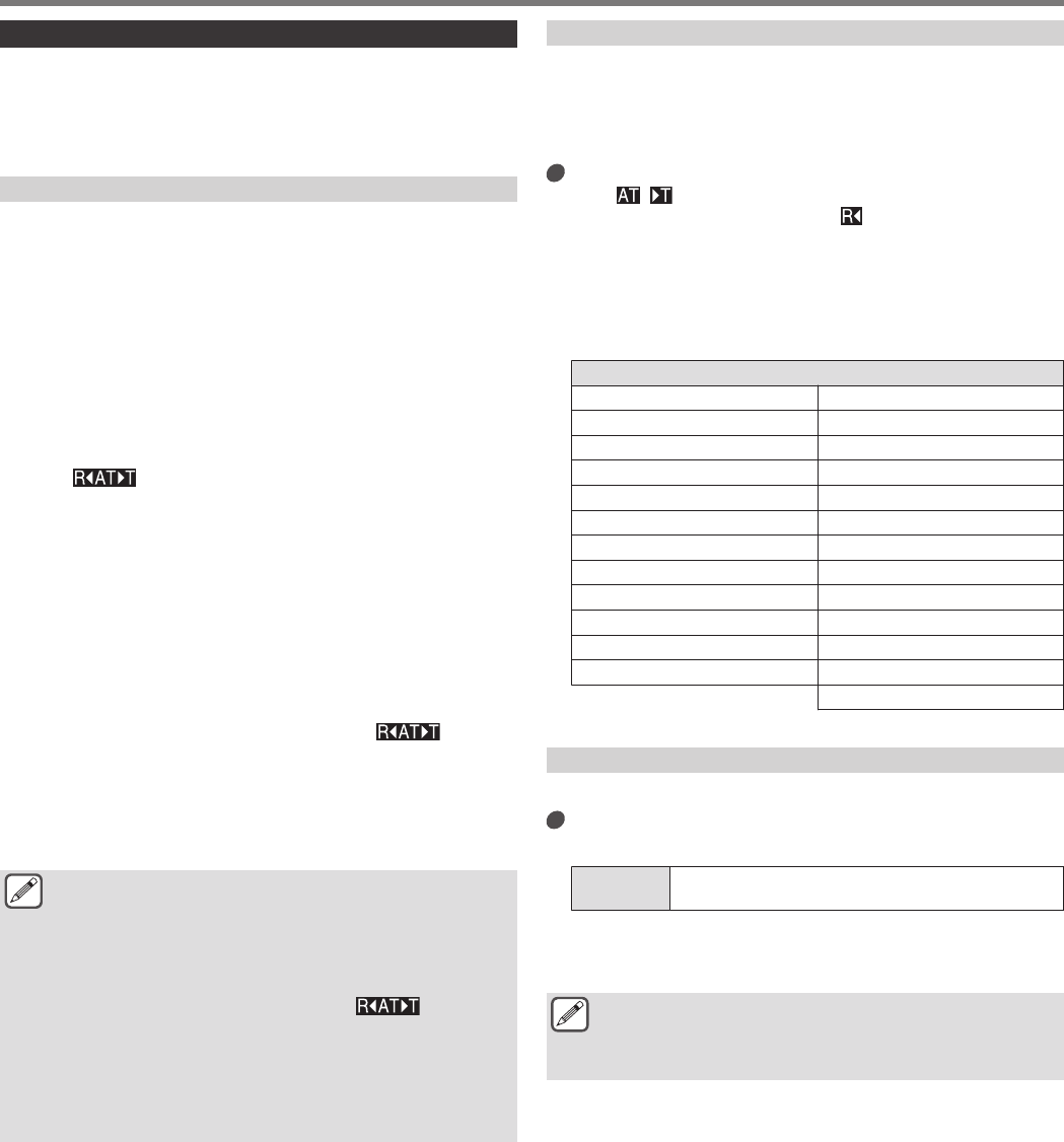
Drive Output (DRV)
The allowable output frequency ranges from the drive output
(DRV) are the 135 kHz band (135.700 kHz to 137.799 kHz), 475
kHz band (472.000 kHz to 478.999 kHz) and the amateur bands
between 1.9 and 50/70 MHz. The output impedance is 50 Ω and
output level is approximately 1 mW (0 dBm).
.
2
4
1
67
3
5
ALC Voltage
+12V
Control Voltage
TX
(Transmission)
Detection
Circuit
AMP
Linear Amplifier
(Typical Input at 1 mW)
Output Power at
Approx. 1 mw (0 dBm)
Connect Using a
Coaxial Cable
GND
ALC
LKY
DRV Connector
REMOTE Connector
(View from Rear Panel)
Turning ON/OFF Drive Output
Press [DRV].
Pressing [DRV] each time toggles drive output between ON and
OFF.
•When drive output is ON, the [DRV] LED lights up in green.
•During output from the DRV terminal, TX signals will not be
output from the ANT 1 and ANT 2 connectors.
•Transmission from the DRV terminal will not be displayed on
the PWR meter. ALC (automatic level control) can be
operated by inputting ALC voltage from an external device
to the ALC terminal of the REMOTE connector. The
operating status will be displayed on the meter in this case.
The DRV output level is not controlled when there is no ALC
voltage input. As such, the output level is determined
according to the MIC input or [CAR] control settings.
●Pay careful attention to the connection when making use
of drive output as described above.
Adjusting the Drive Output Level
Turn the [POWER] control.
“nnn%” is displayed according to the selected drive output
level. [nnn: 5 to 100]
•A different drive output level can be configured for the AM
and modes other than the AM mode.
•The resolution [1% / 5%] for changing the drive output level
can be switched using the Menu 6-04 “Transmit Power Step
Size” setting.
Band/Mode Setting Value
Default
HF
CW/FSK/PSK/SSB/FM/
SSB-DATA/FM-DATA 5 to 100 [%] (1 step or
multiples of 5) 100
AM/AM-DATA 5 to 25 [%] (1 step or
multiples of 5) 25
50M
CW/FSK/PSK/SSB/FM/
SSB-DATA/FM-DATA 5 to 100 [%] (1 step or
multiples of 5) 100
AM/AM-DATA 5 to 25 [%] (1 step or
multiples of 5) 25
70M
(E Type)
CW/FSK/PSK/SSB/FM/
SSB-DATA/FM-DATA 5 to 100 [%] (1 step or
multiples of 5) 100
AM/AM-DATA 5 to 25 [%] (1 step or
multiples of 5) 25
4 BASIC OPERATIONS
4-10
Built-in Antenna Tuner
It is important to ensure that the impedance of the coaxial cable
and that of the antenna coincide with each other. An external
antenna tuner or the built-in antenna tuner is used to adjust the
impedance between the antenna and this transceiver.
Impedance Matching with the Antenna
1Select a TX frequency.
2Press F [ANT] to select an antenna.
•When an external antenna tuner is connected to the ANT 1
connector, select ANT 2 if the built-in antenna tuner is to be
used.
•The built-in antenna tuner cannot be used with ANT 1 when
it is connected to an external antenna tuner.
3Press and hold [AT] to perform tuning.
•The transceiver switches to the CW mode and starts tuning.
TX output power is automatically configured to 10 W and the
SWR meter will be selected as the TX meter.
•<< >> and [AT] LED will start to blink. “R<” blinks
when the antenna tuner is ON during reception.
•To undo the tuning, press [AT] again.
•If the SWR (standing wave ratio) of the antenna is extremely
high (10:1 and above), an alarm tone (“SWR” in the Morse
code) will be output, and the built-in antenna tuner will be
disabled.
•Adjust the antenna to lower the SWR before restarting the
tuning operation.
4Check to ensure that tuning is complete.
•When tuning is completed successfully, a Morse code tone
“T” is output.
•When tuning is complete, the blinking << >> and
[AT] LED become lit in solid light. “R<” blinks when the
antenna tuner is ON during reception.
•If matching is not achieved for a duration of 20 seconds, an
alarm tone will be output (continuous output of “5” in the
Morse code). When this occurs, check the SWR meter and
press [AT] to stop tuning when the SWR value is low.
●Tuning of the built-in antenna tuner will not be performed
outside the permitted TX frequency range.
●During transmission, pressing and holding [AT] starts
the tuning.
●If matching is not achieved for a duration of 60 seconds,
tuning will end automatically. When this occurs, the
antenna tuner circuit turns OFF, << >> will
disappear, and the [AT] LED will go off.
●If tuning does not end automatically even though the
SWR of the antenna 3:1 or lower, adjust the antenna
system to lower the SWR and try to perform tuning again.
●The SWR may not reach 1:1 even though tuning has
ended.
Preset
The tuning results can be stored as preset information in the built-
in antenna tuner according to the preset frequency categories.
When the built-in antenna tuner is ON, the preset information that
corresponds to the current TX frequency is automatically
configured for the built-in antenna tuner.
Press [AT].
•<< >> appears on the screen. When the antenna
tuner is ON while receiving, << >> is displayed. The
preset information that corresponds to the current TX
frequency is configured for the built-in antenna tuner.
•When the TX frequency is altered, the preset information that
corresponds to the preset frequency category is
automatically configured for the built-in antenna tuner.
•To turn off the built-in antenna tuner, press [AT] again.
Preset Frequency Categories for Built-in Antenna Tuner (MHz)
0.030 ≦ f < 1.850 14.100 ≦ f < 14.500
1.850 ≦ f < 2.500 14.500 ≦ f < 18.500
2.500 ≦ f < 3.525 18.500 ≦ f < 21.150
3.525 ≦ f < 3.575 21.150 ≦ f < 21.500
3.575 ≦ f < 3.725 21.500 ≦ f < 25.500
3.725 ≦ f < 4.100 25.500 ≦ f < 28.300
4.100 ≦ f < 6.900 28.300 ≦ f < 29.000
6.900 ≦ f < 7.050 29.000 ≦ f < 30.000
7.050 ≦ f < 7.100 30.000 ≦ f < 51.000
7.100 ≦ f < 7.500 51.000 ≦ f < 52.000
7.500 ≦ f < 10.500 52.000 ≦ f < 53.000
10.500 ≦ f < 14.100 53.000 ≦ f < 60.000
60.000 ≦ f < 74.800 (E type)
Holding Transmission at the End of Antenna Tuning
Transmission can be held after antenna tuning has ended.
Configure in Advanced Menu [7] “TX Hold After
AntennaTuning”
Setting
Value Off (default)/ On
Off: Returns to receiving state after antenna tuning has ended.
On: Continues 10 [W] transmission in the CW mode after
antenna tuning has ended.
●When transmission is held after antenna tuning has
ended, the held status will be canceled when
transmission operations such as [SEND] or PF [DATA
SEND] is performed or when [AT] is pressed.
BASIC OPERATIONS 4
4-11
Switching Antenna Tuner Behavior during Reception
Signals received may be made to pass through the built-in antenna
tuner. Turning ON this function may help to reduce reception
interference from other distant frequencies.
Configure in Advanced Menu [8] “Antenna Tuner
during RX”
Setting
Value Off (default)/ On
Off: Signals received do not pass through the built-in antenna
tuner.
On: Signals received pass through the built-in antenna tuner.
●When full break-in is ON in the CW mode, the antenna
tuner will function during reception regardless of the
above setting.
●If the TX and RX frequencies are different during split
operation, the antenna tuner will not function during
reception regardless of the above setting.
Configuring the Built-in Antenna Tuner Behavior for
Each Band
Two options to either store the ON/OFF status of the built-in
antenna tuner separately for each band category or to store the
same status for all bands are available.
Configure in Advanced Menu [9] “Antenna Tuner
Operation per Band”
Setting
Value Off (default)/ On
Off: Stores the same ON/OFF status of the built-in antenna
tuner for all bands.
On: Stores the ON/OFF status of the built-in antenna tuner for
each band category.
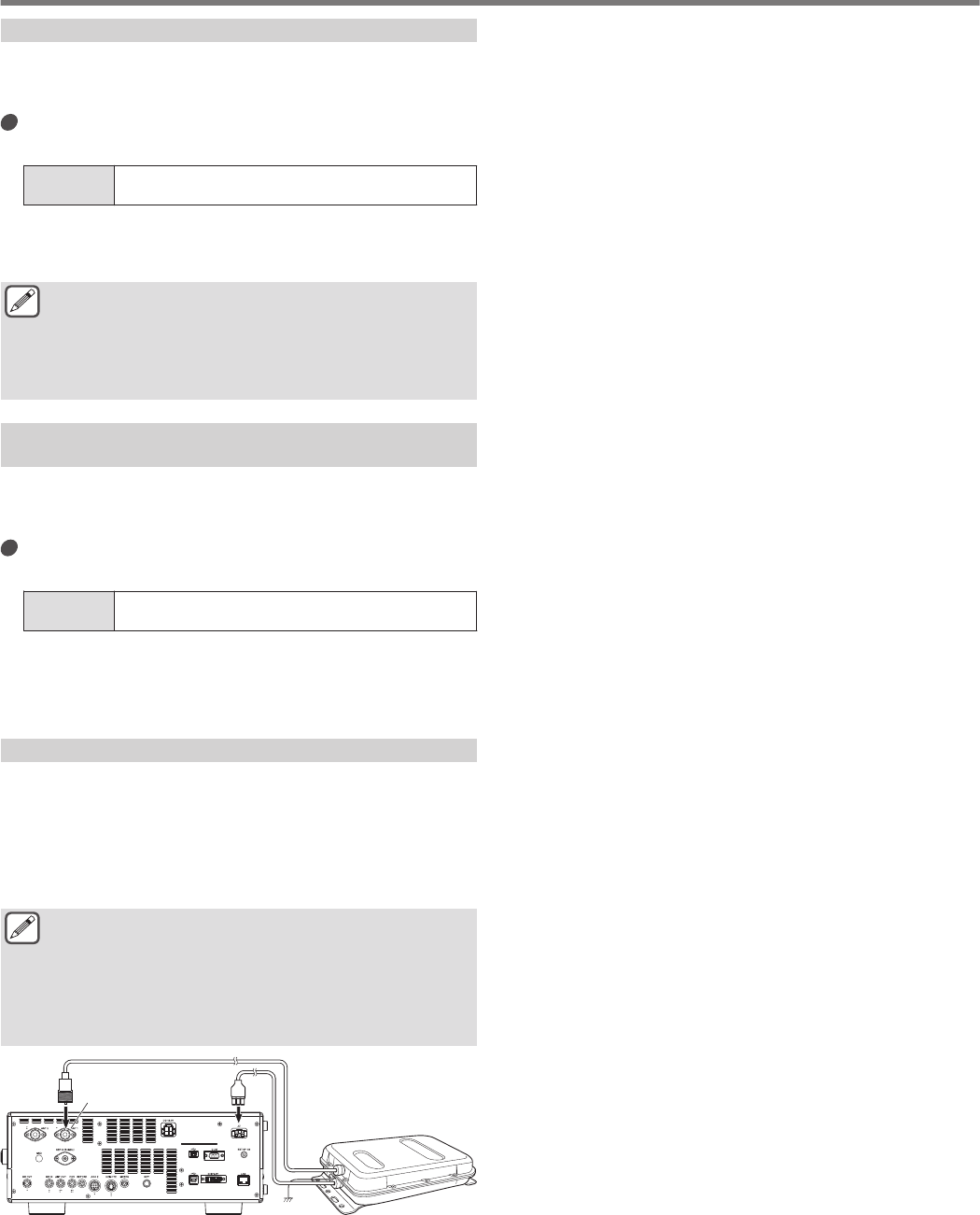
Connecting the External Antenna Tuner AT-300
To use the external antenna tuner AT-300, connect it to the ANT
1 connector and AT connector.
•AT-300 will not function if it is connected to the ANT 2 connector.
AT connector is a control terminal that is used exclusively for
AT-300. It cannot be used to control other external antenna
tuners. When an external antenna tuner other than AT-300 is
connected, make use of TX tuning.
●AT-300 cannot be used with the 50/70 MHz band. When
using a 50/70 MHz band antenna, connect it to the ANT
2 connector.
●When AT-300 is connected to the AT connector and ANT
1 is used, the signal bypasses the built-in antenna tuner
circuit.
●Production of the AT-300 has been discontinued.
.
AT-300
ANT 1
Connector
TS-890
4 BASIC OPERATIONS
4-12
Split Operation
The same frequency is used for both reception and transmission
during normal communication. Select either VFO A or VFO B in
this case. However, depending on the circumstances, a different
frequency may be chosen for reception and transmission. In this
case, it is necessary to use two VFOs. This is known as “split
operation”. “Split operation” is used in cases such as when using
an FM repeater or when calling a DX station.
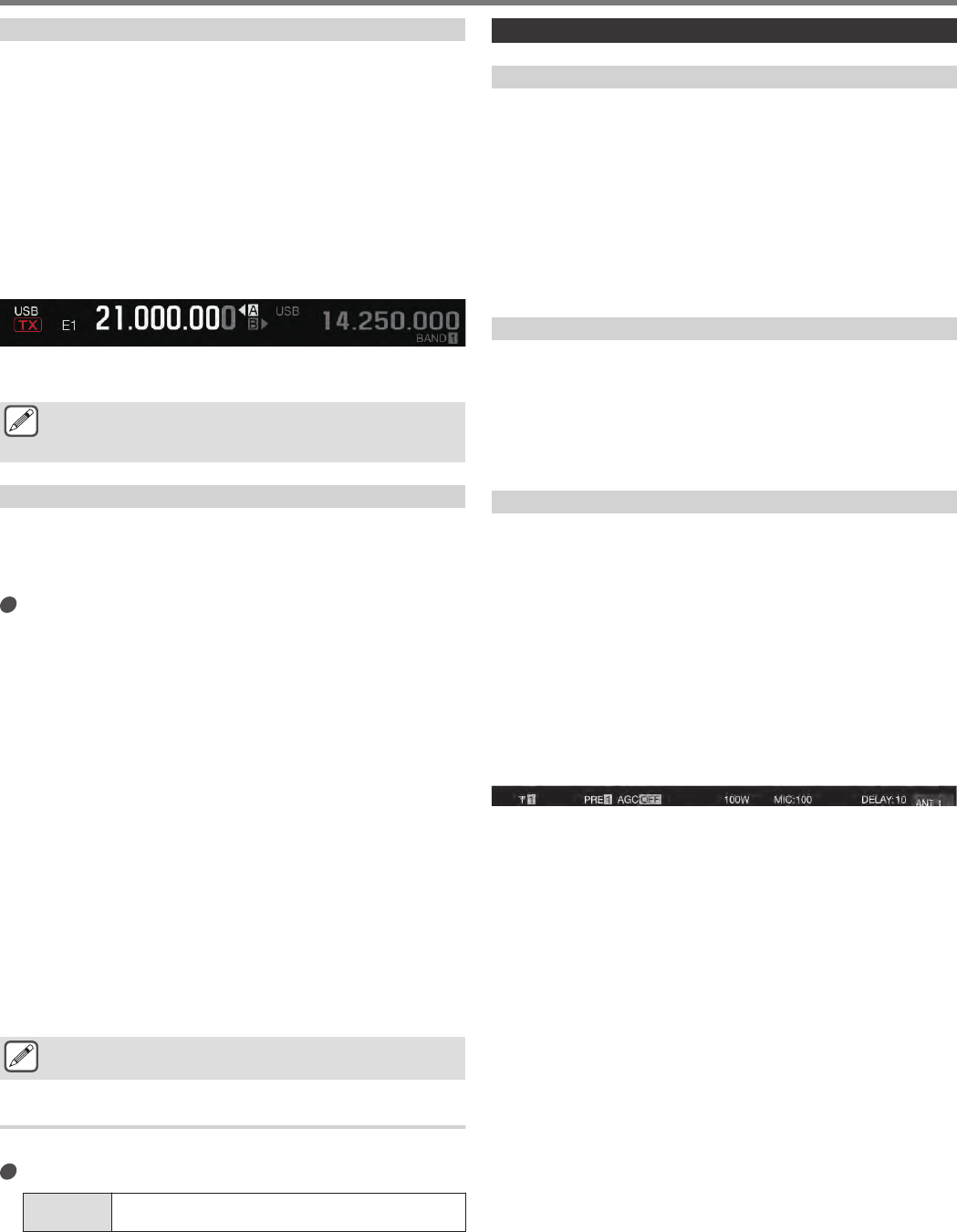
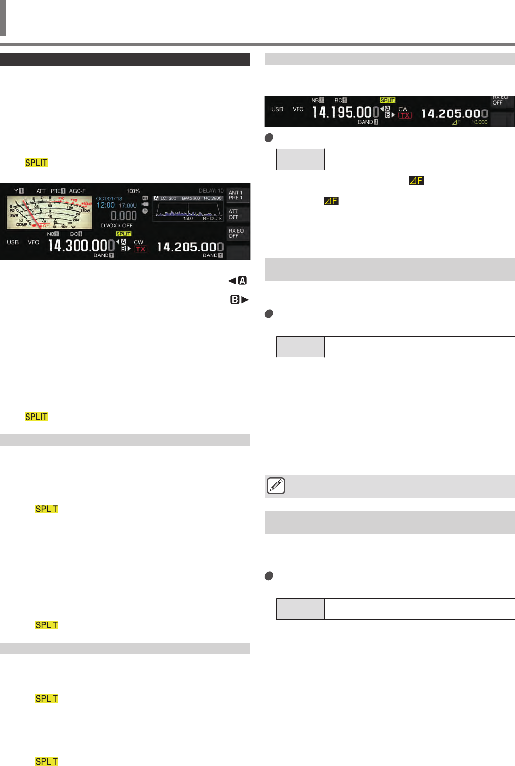
1Press [SPLIT].
<< >> lights up when the transceiver enters the split
mode.
.
2Press [A/B] to select “VFO A” or “VFO B”.
The value on the left is the RX frequency. (Indicated by
in the example)
The value on the right is the TX frequency. (Indicated by
in the example)
3Select a frequency.
•To copy a selected VFO frequency to the other VFO, press
and hold [A/B].
4Press [A/B] to select the other VFO.
5Select a frequency.
Exiting Split Operation
6Press [SPLIT].
The transceiver switches to the simplex mode and the light for
<< >> goes off.
Direct Input of Frequency Difference Specified by DX Station
To directly configure the frequency difference between the
frequency specified by the DX station and the RX frequency,
perform the steps below while receiving signals from the DX
station.
1Press and hold [SPLIT].
•<< >> starts to blink.
2Enter the frequency specified by the DX station in
units of kHz.
To exit the configuration process, press [CLR].
If the frequency specified by the DX station is a positive value, enter
the specified frequency in units of kHz using the numeric keypad.
If the frequency specified by the DX station is a negative value,
enter a “0” at the beginning of the frequency value.
For example, if “+5 kHz” is specified, enter “5”. If “-5 kHz” is
specified, enter “0” followed by “5”.
After input is complete, the TX frequency is configured and split
operation is now enabled.
•<< >> changes from a blinking to a solid display.
Turning the Tuning Control to Search for a TX Frequency
To search for a TX frequency, perform the steps below while
receiving signals from the DX station.
1Press and hold [SPLIT].
•<< >> starts to blink.
2Turn the Tuning control to search for a TX frequency.
To exit the configuration process, press [CLR].
3Press [SPLIT].
The frequency that is found in step 2 is configured as the TX
frequency and split operation is now enabled.
•<< >> changes from a blinking to a solid display.
⊿F Display
This item displays the difference between the RX frequency and
TX frequency during split operation.
.
Configure in Menu [6-15] “Delta Frequency Display”
Setting
Value Off/ On (default)
•When the ⊿F display is ON, << >> is displayed below
the TX frequency display during split operation.
•When << >> is displayed below the TX frequency, the
band memory number on the right will not be displayed.
•When RIT or XIT is ON, the ⊿F value is the difference
between the TX frequency and the RX frequency with the
RIT or XIT frequency added.
Changing the split frequency using the [RIT/XIT]
control
While in the split mode with the RIT/XIT function set to OFF, the
split frequency can be adjusted by turning the [RIT/XIT] control.
Configure in Menu [3-12] “Split Frequency Offset by
RIT/XIT Control”
Setting
Value Off (default)/ TX Frequency Offset while RX/ RX
Frequency Offset while TX/ Both
TX Frequency Offset while RX: Split transmission frequency
can be adjusted while receiving. While receiving signals from a
DX-pedition station, turning the [RIT/XIT] control changes the
TX frequency in advance to the frequency specified by the
target station.
RX Frequency Offset while TX: Split reception frequency can
be adjusted while transmitting. While one’s own station is
transmitting as a DX-pedition station, turning the [RIT/XIT]
control changes the RX frequency in advance to the frequency
specified for the target station.
Both: Enables both the above.
●Adjustment of the split frequency using this function is
disabled during TF-SET.
Configuring the Band Direct Key during Split
Operation
Three options are available for selection with regard to the
behavior when the band direct key is pressed during split
operation.
Configure in Menu [3-13] “Band Direct Keys in Split
Mode”
Setting
Value RX Band (default)/ RX Band and Cancel Split Mode/
RX/ TX Band
RX Band: Changes the receiving band.
RX Band and Cancel Split Mode: Changes the receiving
band and cancels the split mode.
RX/TX Band:
•Changes both the receiving and transmitting bands at the
same time.
•The transmitting band and receiving band is assigned with
the same memory number.
•Each band can be adjusted while maintaining the split status.
COMMUNICATING AIDS 5
5 COMMUNICATING AIDS
5-1
TF-SET (Setting the TX Frequency)
TF-SET is a function for temporarily switching the TX frequency
and RX frequency. Signals can be received at one’s own
frequency while the TF-SET switch is pressed and held down, and
the TX frequency can also be changed in this state. Doing so
allows checking of whether there is interference in the newly-
selected TX frequency.
•A call is made to the target station when there is no interference
and at the right timing to ensure smooth communication with DX
stations that are receiving calls from a large number of stations.
In other words, the communication status of the DX station in
the presence of interfering signals are taken into consideration
and transmission is carried out using the TF-SET function at the
instant when the DX station is in the receiving state and there is
no transmission from other stations. Putting this function to
good use enables communication with a larger number of DX
stations.
1Configure the split operation frequency.
2Press and hold [TF-SET].
The TX frequency and RX frequency are switched.
3Turn the Tuning control while pressing and holding
[TF-SET], or press [UP]/[DWN] on the microphone.
Signals are received at the new TX frequency.
4Release [TF-SET].
Reception starts at the original RX frequency.
●Adjustment of the split frequency using the [RIT/XIT]
control is disabled during TF-SET.
●Turning on the frequency lock before using the TF-SET
function helps to prevent the transceiver from losing
communication with the DX station due to erroneous
operation.
AGC
AGC (Automatic Gain Control) is a function for controlling the IF
gain automatically so as to minimize fluctuations in the strength of
the signal that is being received.
•The AGC time constant is configured to FAST, MID or SLOW
according to the receiving status and operation mode (other
than FM mode).
•The digital AGC circuit of this transceiver divides the time
constant into 20 levels from SLOW to FAST, with “1” being the
fastest and “20” the slowest.
•Generally, the time constant is configured to a fast time constant
in the CW and FSK modes where fluctuations in the signal
strength are well defined, and a slow time constant is used in
the SSB and AM modes where changes are gradual.
•However, a fast time constant is also useful in the SSB and AM
modes to perform tuning quickly or when receiving weak
signals.
•AGC can also be turned off.
•A different default time constant for AGC is configured for each
mode as shown below.
Default AGC Time Constant Setting
Mode Setting Display
SSB SLOW AGC-S
SSB-DATA SLOW
CW FAST
AGC-FFSK FAST
PSK FAST
AM SLOW AGC-S
AM-DATA SLOW
Switching the AGC Time Constant
1Select a mode other than FM.
2Press [AGC] to select an AGC time constant.
Pressing [AGC] each time switches the selection in the
following sequence: “AGC-F” → “AGC-M” → “AGC-S”.
.
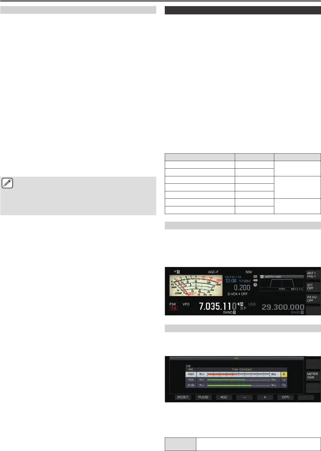
Adjusting the AGC Time Constant Preset Value
1Press and hold [AGC] to display the AGC
configuration screen.
.
2Press F3 [AGC] or [AGC] to select “FAST”, “MID” or
“SLOW”.
3Press F4 [–]/ F5 [+] or turn the [MULTI/CH] control
to change the AGC time constant.
Setting
Value 1 to 20
5 COMMUNICATING AIDS
5-2
The AGC time constant is fastest when it is configured to “1”, and
slowest when configured to “20”.
•The default AGC time constant values in the respective
operation modes are as follows.
Mode FAST MID SLOW
SSB 9 12 14
SSB-DATA 9 12 14
CW 9 12 14
FSK 7 11 14
PSK 7 11 14
AM 9 13 16
AM-DATA 9 13 16
AGC OFF
Turns off AGC according to the status of the signals received. RF
gain is fixed when AGC is set to OFF, which makes it easier to hear
weak signals in some cases.
●If AGC is turned OFF while the S meter is deflecting due
to the signal, sound may be output to the speaker or
headphones at an unexpectedly loud volume.
Turn the [RF] control to turn down the RF gain level in advance.
After turning off AGC, adjust RF gain by turning the [RF] control
until the signal can be heard clearly.
To turn off AGC, perform the steps below.
1Press and hold [AGC] to display the AGC
configuration screen.
2Press and hold F6 [(OFF)] to configure AGC to OFF.
<<AGC OFF>> lights up and the preset value display area is
grayed out.
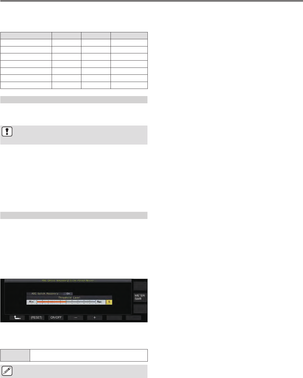
AGC Quick Recovery
This function performs recovery from the suppression that occurs
when the RX signal contains pulse noise. The strength of pulse
noise at which this function is activated is determined by adjusting
the threshold level.
1Press and hold [AGC] to display the AGC
configuration screen.
2Press F2 [PULSE] to display the AGC Quick
Recovery configuration screen.
.
3Press F3 [ON/OFF] to set the function to “On”.
4Press F4 [–]/ F5 [+] or turn the [MULTI/CH] control
to change the threshold level.
Setting
Value 1 to 5 (default) to 10
●This function may not be effective for pulse noise
occurring in short time interval.
COMMUNICATING AIDS 5
5-3
RX Equalizer
This function allows the sound quality to be altered by adjusting
the characteristics of the RX frequency. 6 types of RX equalizer
are available, which can be configured separately for each mode.
A set of equalizer characteristics can be configured freely for each
of the options between “User 1” and “User 3”.
Turning ON/OFF RX Equalizer
Press F [RX EQ].
Pressing F [RX EQ] each time toggles the RX equalizer
between ON and OFF.
Selecting an RX Equalizer Characteristic
1Press and hold F [RX EQ] to display the RX
Equalizer configuration screen.
.
2Press F2[ ] / F3[ ] or turn the [MULTI/CH]
control to select an equalizer characteristic.
The selected equalizer characteristic turns on.
Characteristic Purpose
High Boost 1 (HB1) Boosts the high frequency component. This is
effective for audio sound that contains a low
frequency component.
High Boost 2 (HB2) Boosts the high frequency component. The low
frequency attenuation level for this option is half of
that of the High Boost 1 option.
Formant Pass (FP) This option attenuates frequency components that
is outside the audio bandwidth so that the audio
can be heard more clearly.
Bass Boost 1 (BB1) Boosts the low frequency component. This is
effective for audio sound that contains a high
frequency component.
Bass Boost 2 (BB2) Boosts the low frequency component. The low
frequency is further boosted compared to Bus
Boost 1.
Flat (FLAT) This option has a flat frequency response.
User 1 (U1) Frequency characteristics can be adjusted
according to the user’s preferences and stored in
the options between User 1 and User 3. The flat
frequency characteristic is selected in the default
setting.
User 2 (U2)
User 3 (U3)
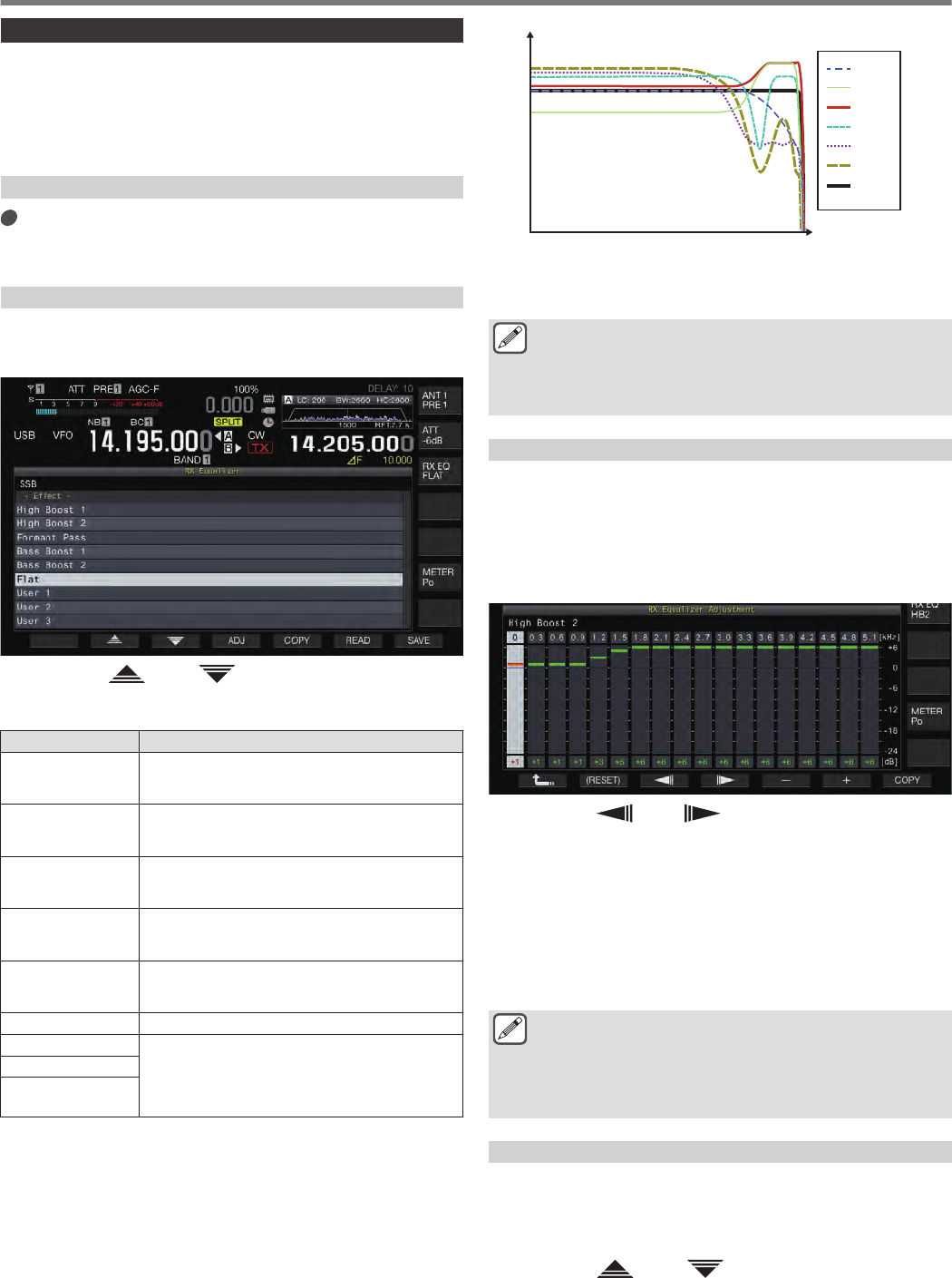
.
RX Characteristic Curve
Frequency
(Hz)
-30
-25
100103
102
101
0
5
-5
-10
-20
-15
10
OFF
HB1
HB2
FP
BB1
BB2
FLAT
●When the RX DSP equalizer is set to ON, the effect
(“HB1”/ “HB2”/ “FP”/ “BB1”/ “BB2”/ “FLAT”/ “U1”/ “U2”/
“U3”) is displayed at the lower end of the key guide.
●When the RX DSP equalizer is OFF, “OFF” is displayed
at the lower end of the key guide.
Adjusting the Equalizer Characteristics
The equalizer characteristics can be customized according to the
user’s preferences. Also, the customized characteristics can be
stored as user-defined settings.
1Select a equalizer characteristic.
2Press F4 [ADJ] to display the RX Equalizer
Adjustment screen.
.
3Press F3[ ] / F4[ ] to select the frequency to
adjust.
4Press F5 [–]/ F6 [+] or turn the [MULTI/CH] control
to adjust the frequency level.
•Touching a point on the RX Equalizer Adjustment screen
selects the corresponding band and changes the frequency
to the selected level.
An alternative way is to touch a rough point followed by fine-
tuning in steps 3 and 4.
•Pressing and holding F2 [(RESET)] resets all the frequency
levels to the default setting.
●Besides the User 1 to User 3 options, the equalizer
characteristics of the other options can also be altered
on the RX Equalizer Adjustment screen.
●If the configured level of the RX DSP equalizer deviates
from the configured level of the adjacent frequency, the
desired amount of attenuation may not be obtained.
Copying Equalizer Data
The customized equalizer characteristics can be copied to one of
the options from “User 1” to “User 3”.
1Press and hold F [RX EQ] to display the RX
Equalizer configuration screen.
2Press F2[ ] / F3[ ] to select the equalizer to
save.
•Pressing F4 [ADJ] on the RX Equalizer screen displays the RX
Equalizer Adjustment screen. Equalizer data can be copied from
either the RX Equalizer screen or RX Equalizer Adjustment screen.
5 COMMUNICATING AIDS
5-4
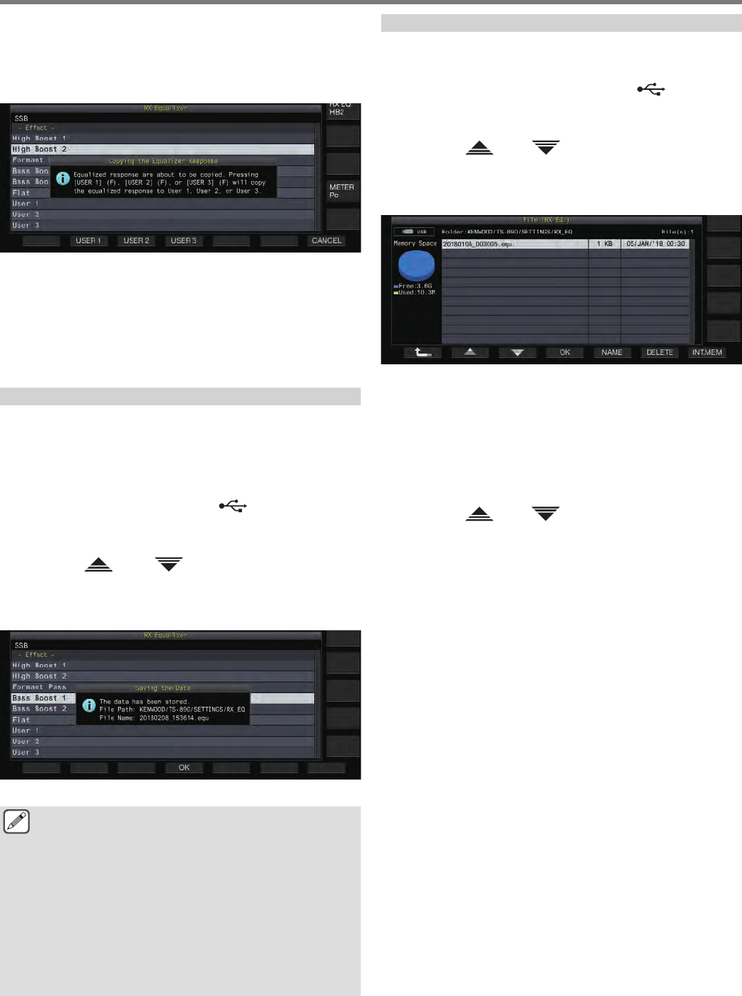
3Press F5 [COPY].
A message appears prompting you to confirm the destination
to copy the equalizer characteristics.
•Pressing F7 [CANCEL] ends the equalizer data copy
operation without copying and restores the display to the RX
Equalizer screen or RX Equalizer Adjustment screen.
.
4Press F2 [USER 1], F3 [USER 2] or F4 [USER 3] to
specify the destination to copy the data to.
The equalizer selected in step 2 is copied to “USER 1”, “USER
2” or “USER 3”.
•After copy is complete, the message to confirm the
destination for copying the equalizer characteristics
disappears and the display is restored to the RX equalizer
screen or RX equalizer adjustment screen.
Saving Equalizer Data
Multiple sets of customized DSP equalizer settings data can be
created and saved.
•Before doing so, configure the destination for saving the data in
“File Storage Location” of the “USB/File Management Menu” to
“Internal Memory” or “USB Flash Drive”. (See 11-2)
•To save the data to a USB flash drive, insert a USB flash drive
formatted using this transceiver into (USB-A).
1Press and hold F [RX EQ] to display the RX
Equalizer configuration screen.
2Press F2[ ] / F3[ ] to select the equalizer to
save.
3Press F7 [SAVE].
A message indicating that saving is complete is displayed.
.
4Press F4 [OK].
●The saved file is named in the “yyyymmdd_hhmmss”
format. The extension of the saved file is “.equ”.
(Example) If the date is 10:20:30 a.m., February 15, 2018:
20180215_102030.equ
●The name of the destination folder is as follows. (The
name varies depending on the destination for saving
files.)
•USB flash drive: “KENWOOD\TS-890\SETTINGS
\RX_EQ”
•Built-in memory: “SETTINGS\RX_EQ”
●When removing the USB flash drive, make sure to
execute “Safe Removal of USB Flash Drive”. (See
11-6)
Reading Equalizer Data
RX DSP equalizer data that is saved in the internal memory or USB
flash drive can be read.
•To read the data from a USB flash drive, insert the USB flash
drive containing the RX equalizer data into (USB-A).
1Press and hold F [RX EQ] to display the RX
Equalizer configuration screen.
2Press F2[ ]/ F3[ ] to select the equalizer to
read.
3Press F6 [READ] to display the screen for selecting
the file to read.
.
4Select the file to read.
•To read data from the internal memory, press F7 [INT.MEM].
•To read data from the USB flash drive, press F7
[USB.MEM]. (If a USB flash drive is not connected, a message
screen will appear prompting you to get ready the USB flash
drive.)
•Pressing F5 [NAME] allows the file name to be changed.
•Pressing F6 [DELETE] displays a message to confirm
deletion of the file. Pressing F4 [OK] deletes the file.
5Press F2[ ]/ F3[ ] to select the RX equalizer
data file to read.
Alternatively, the RX equalizer data file can also be selected by
turning the [MULTI/CH] control.
6Press F4 [OK].
•After the RX equalizer data has been read successfully, a
message indicating that reading is complete is displayed.
7Press F4 [OK] to end the process.
COMMUNICATING AIDS 5
5-5
Preamplifier
The preamplifier can be configured to one of the two options: low
gain type that places priority on IMD (PRE 1) and high gain type
that places priority on sensitivity (PRE 2).
Press F [ANT/PRE].
Pressing F [ANT/PRE] each time switches the selection in the
following sequence: “PRE 1” → “PRE 2” → “OFF”.
•The preamplifier selection is stored for each antenna
selection band.
•The default values are as follows.
Less than 7.5 MHz: OFF
7.5 MHz to less than 21.5 MHz: PRE 1
More than 21.5 MHz: PRE 2
RX Monitor
If weak signals are received while the squelch is closed, the signals
tend to be interrupted. Also, you may sometimes want to monitor
the condition of the RX frequency while in the CTCSS standby
state. In this case, the RX monitor is used to open the squelch
temporarily.
“RX Monitor” (Menu [0-15] to [0-31]) can be assigned to a PF key.
While the PF key that is assigned with “RX Monitor” is pressed and
held down, the squelch opens and the RX frequency can be
monitored. The RX monitor turns OFF once the key is released.
Scanning is paused while PF [RX Monitor] is pressed.
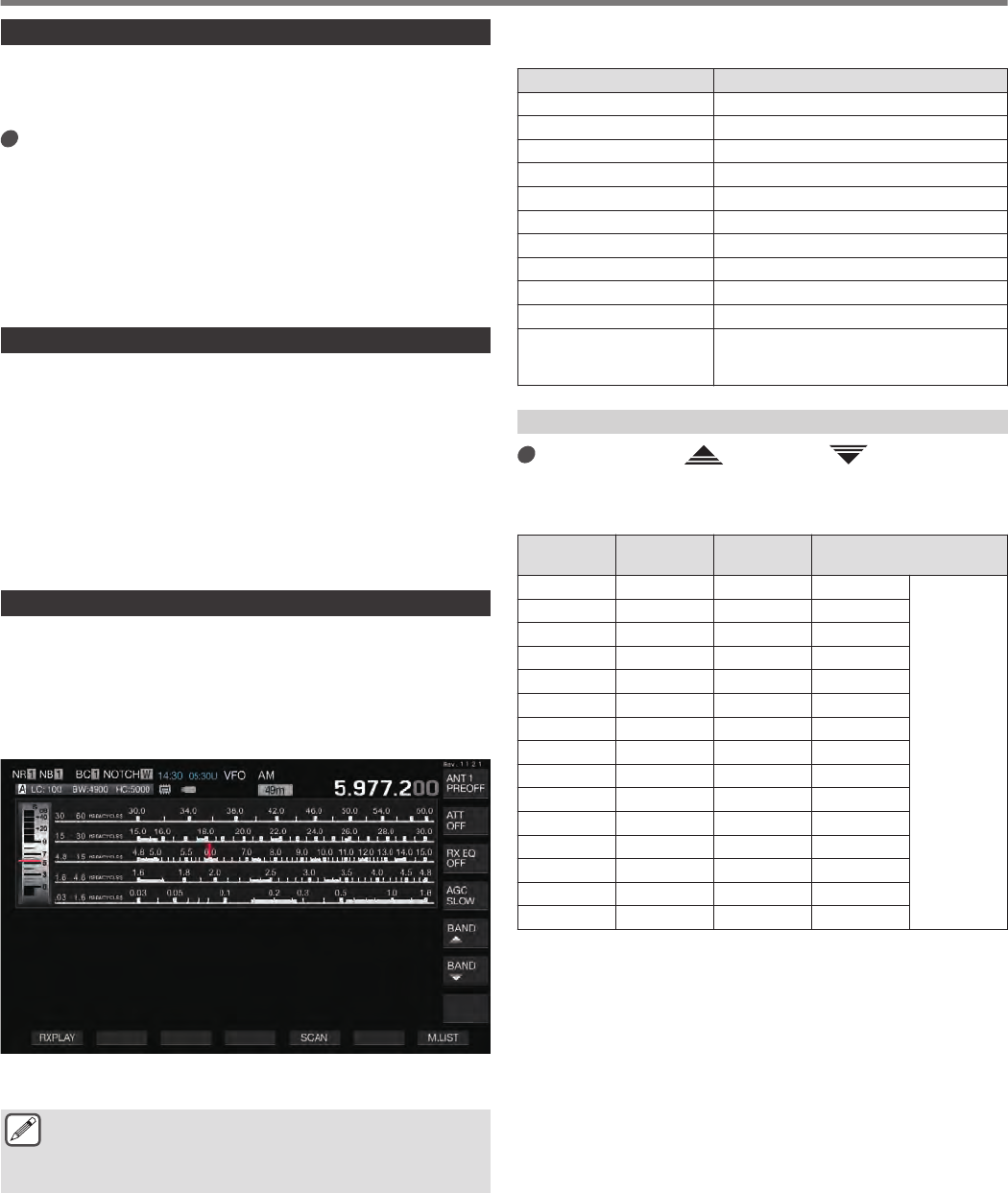
SWL (BCL) Mode
The SWL (BCL) mode is intended for SWL (Short Wave Listening)
and BCL (Broadcast Listening) by displaying the horizontal dial of
the “9R-59” communications receiver on the screen.
1Press F [SWL] on the menu screen to display the
SWL screen.
.
2Press [MENU] followed by F [SWL].
Returns to the normal screen.
●Switching to the SWL mode is not possible while the
transverter is ON.
●An indicator is not displayed if a memory channel that is
not registered is being called up.
•Restrictions are applied to the following functions in the SWL
mode.
Function Status
Transmission Disabled
Sending of voice message Disabled
Decoding/Encoding Disabled
Sending of CW message Disabled
TX output power limiter Disabled
Meter switching Disabled
TX filter switching Disabled
Turning ON transverter Disabled
FM tone Disabled
Antenna tuning Disabled
Configuration of the TX
equalizer and related
settings Disabled
Band Switching in the SWL Mode (VFO Mode)
Press F [BAND ]/ F [BAND ].
•The “broadcast/meter band” is displayed when the
frequency falls within the band range. The preset broadcast
bands are shown in the table below.
Broadcast/
Meter Band Lower Limit
[kHz] Upper Limit
[kHz] Default [kHz]/ Mode
LW 145 285 145
AM
MW 525 1705 525
120 m 2300 2495 2300
90 m 3200 3400 3200
60 m 4750 5060 4750
49 m 5900 6200 5900
41 m 7200 7450 7200
31 m 9400 9900 9400
25 m 11600 12100 11600
21 m 13570 13870 13570
19 m 15100 15800 15100
16 m 17480 17900 17480
15 m 18900 19020 18900
13 m 21450 21850 21450
11 m 25670 26100 25670
•The band segments of the SWL mode that is preconfigured on
this transceiver are represented in a slightly different way
compared to conventional meter bands. Different band
segments are used so as to achieve wider coverage to include
the broadcast bands of the different regions and other bands.
5 COMMUNICATING AIDS
5-6

Transmission in Data Mode
Transmission via PTT Switch, SS Terminal and SEND
Switch transmission by making use of the [PTT] switch on the
microphone, SS terminal of the REMOTE connector and [SEND]
on the front panel. Under normal circumstances, the microphone
audio is transmitted via this operation.
•This transceiver continues to transmit signals while the [PTT]
switch is pressed and held down.
•This transceiver transmits signals when the SS terminal of the
REMOTE connector is short-circuited to GND.
•Pressing [SEND] each time toggles between transmission and
reception.
Transmission via DATA PTT or DATA SEND
DATA PTT (PKS terminal of ACC 2 connector) or the PF key that
is assigned with “DATA SEND” is used to switch between
transmission and reception. For more details, please refer to “PF
Keys (Programmable Function Keys)”.
This function comes in handy when transmitting audio or data from
an external device.
This operation transmits normal audio signals or audio signals that
are input to the ANI terminal of the ACC 2 connector. A different
audio path can be specified. For more details, please refer to
“Configuration of the Input Path of TX Audio” (8-1).
•This transceiver continues to transmit signals while DATA PTT
(PKS terminal of the ACC 2 connector) is short-circuited to
GND.
•Pressing the PF key that is assigned with “DATA SEND” toggles
between transmission and reception.
RIT/XIT
RIT (Receiver Incremental Tuning)
RIT is a function for fine-tuning only the RX frequency in 10 Hz
steps within the ±9.99 kHz range without altering the TX frequency.
This is used when the TX frequency of the station that this
transceiver is communicating with has become slightly deviated.
•When the FINE mode is ON, the offset frequency of RIT
switches to a step size of 1 Hz. RIT functions in the same way
in all modes as well as when VFO or the memory channel mode
is in use.
1Press [RIT].
The [RIT] LED lights up and the RIT offset frequency is
displayed.
2Turn the [RIT/XIT] control.
Fine-tune the RX frequency for RIT.
•To clear the offset frequency for RIT, press [CL]. The RIT
offset frequency value is reset to 0.
3Press [RIT] to end the process.
RIT is turned off. The RX frequency is restored to the value prior
to performing step 1.
RIT Shift
This is a function for setting the frequency adjusted with RIT to a
RX band.
Press and hold [RIT].
The RX frequency that is adjusted using RIT is set to a RX band
and the RIT function is turned off.
XIT (Transmitter Incremental Tuning)
XIT is a function that can be used to fine-tune the TX frequency in
10 Hz steps within the ±9.99 kHz range without altering the RX
frequency.
•When the FINE mode is ON, the offset frequency of XIT
switches to a step size of 1 Hz.
1Press [XIT].
The [XIT] LED lights up and the XIT offset frequency is
displayed.
2Turn the [RIT/XIT] control.
Fine-tune the TX frequency for XIT.
•To clear the offset frequency for XIT, press [CL]. The XIT
offset frequency value is reset to 0.
3Press [XIT] to end the process.
XIT is turned off. The TX frequency is restored to the value prior
to performing step 1.
XIT Shift
This is a function for shifting from operation using XIT to the split
mode at one touch.
Press and hold [XIT].
When the TX frequency that is adjusted using XIT is set to a TX
band, operation switches to the split mode at the same time and
the XIT function is turned off.
●If the frequency is changed in the entry mode, the
RIT/XIT function is automatically turned off.
COMMUNICATING AIDS 5
5-7
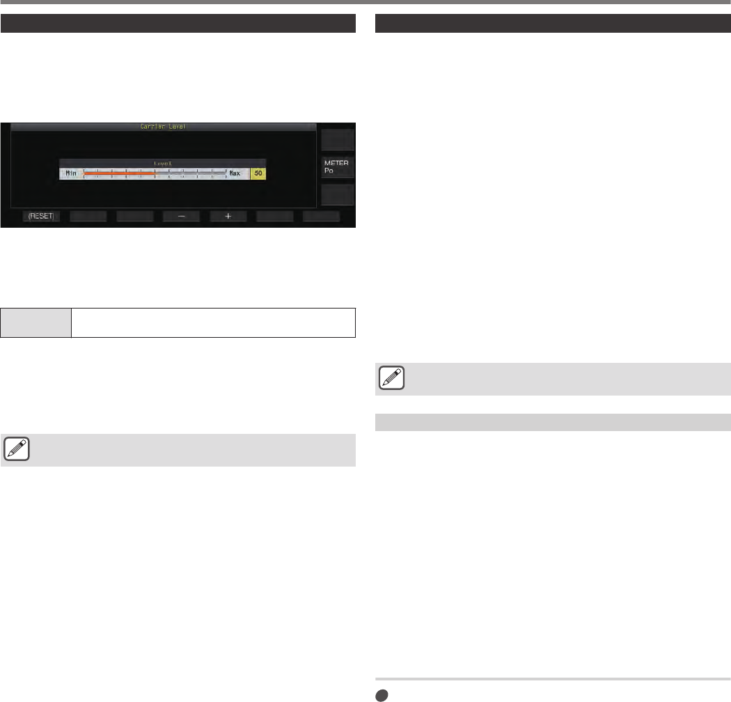
Adjusting the Carrier Level
The steps to adjust the carrier level in the CW, FSK, PSK and AM
modes are as follows.
1Press [CAR] to display the Carrier Level
configuration screen.
.
2Transmit in the CW, FSK, PSK or AM mode.
3Press F4 [–]/ F5 [+] or turn the [MULTI/CH] control
to adjust the carrier level while referring to the ALC
meter.
Setting
Value 0 to 50 (default) to 100 (1 step)
•CW/ FSK mode: Adjust the carrier level while ensuring that the
ALC meter reading does not exceed the ALC zone.
•AM/ PSK mode: Adjust the carrier level until the ALC meter
needle starts to deflect.
•SSB/ FM mode: The carrier level value is fixed. (Cannot be
adjusted)
●Note that the TX output will be disabled if the setting
value of carrier level is “0”.
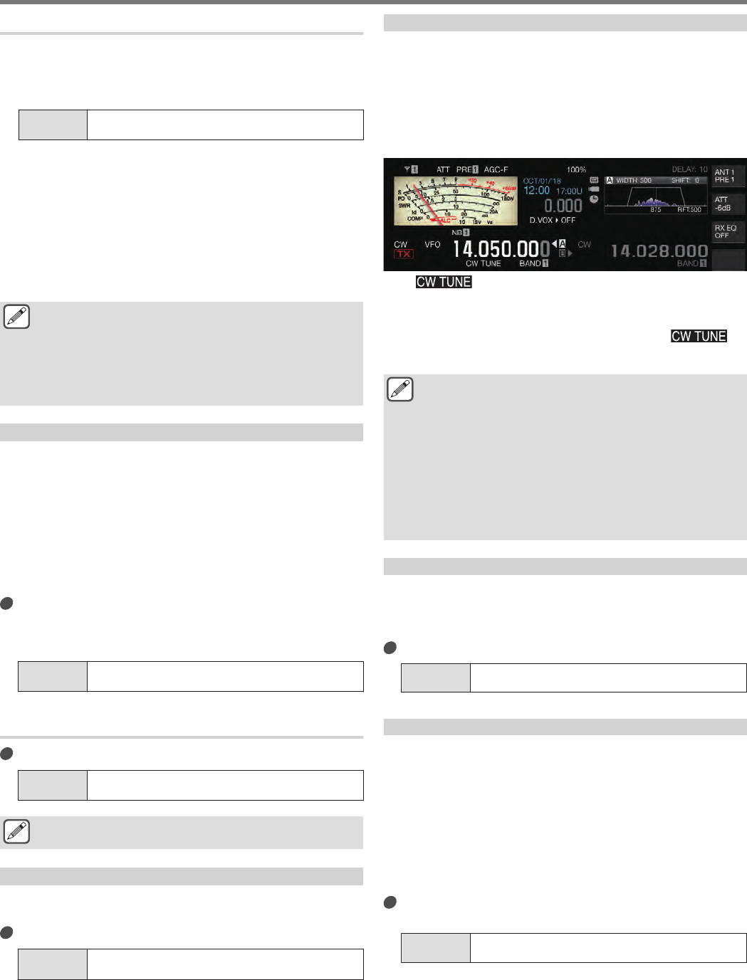
Operation in CW Mode
In the world of amateur radio, there is active communication in the
CW mode. This is because this mode of communication consumes
less power than SSB, and can be regarded as the simplest type of
digital communication that combines the use of “dots” and
“dashes”.
•The built-in electronic keyer of this transceiver offers a wide
variety of functions to support the operation of the users. For
more details, please refer to “Electronic Keyer”.
1Select band and frequency.
Select a frequency band and configure the frequency.
2Press [CW/ CW-R] to select CW mode.
3Press [SEND] to transmit.
4Operate the electronic keyer or paddle to transmit
a Morse code signal.
While transmission is in progress, a sidetone for monitoring the
Morse code of one’s own station can be heard. The frequency
of the sidetone changes in tandem with the pitch frequency.
5After the Morse code is transmitted, press [SEND]
to end the transmission.
This transceiver is restored to the receiving state.
●The sidetone volume can be adjusted in Menu [1-02]
“Sidetone Volume”.
CW Break-in
Break-in is a convenient function that places this transceiver in the
TX mode simply by switching to the key-down state when in the
CW mode, and restores this transceiver to the RX mode upon
switching to the key-up state. Break-in is divided into 2 types, full
break-in and semi break-in.
Full Break-in
Switches this transceiver from the TX mode to the RX mode at
almost the same time as the key-up operation.
Semi Break-in
This transceiver does not return to the RX mode immediately after
the key-up operation, but remains in the TX mode and switches to
the RX mode only after the preconfigured delay time has elapsed.
Turning ON/OFF Break-in
Press [VOX].
Pressing [VOX] each time toggles break-in between the ON
and OFF states.
•When break-in is ON, the [VOX] LED lights up.
5 COMMUNICATING AIDS
5-8
Adjusting the Break-in Mode and Break-in Delay Time
1Press [VOX] to set break-in to ON.
2Turn the [DELAY] control to adjust the delay time
after key-up.
Setting
Value FULL-BK/ 50 to 500 (default) to 1000 [ms] (50 step)
•Turn the [DELAY] control all the way to the left, and the full
break-in mode is activated when “FULL-BK” is displayed.
•Turning the control to the right lengthens the delay time while
turning the control to the left shortens it.
•“FULL-BK” or “DELAY:nn” ([nn: 1 to 20 (equivalent to 50ms
to 1000ms)]) is displayed at the top right corner of the filter
information area.
3Operate the electronic keyer or paddle.
Transmission/reception is repeated automatically according to
the dot and dash Morse code.
●Before using this transceiver in combination with a linear
amplifier, check whether the linear amplifier supports full
break-in. If its compatibility with full break-in is unknown
or if it is not compatible, operate using the semi break-in
mode.
●Full break-in and semi break-in cannot be used at the
same time.
Adjusting the Sidetone and Pitch Frequency
•During key-down in the CW mode, a tone can be heard from the
speaker of this transceiver. This tone is known as a sidetone.
When this tone is heard, it means it is possible to monitor the
Morse code transmitted by one’s own station.
•In the CW mode for direct keying of the carrier, a BFO (beat
frequency oscillator) is needed to convert the carrier wave into
audible sound. The difference in frequency between the BFO
and carrier wave can be heard in the form of a beat. This
difference in frequency is called RX pitch.
•Both the sidetone and the RX pitch have the same frequency.
Turn the [MIC/PITCH] control.
Configure to a sidetone frequency that can be heard most
clearly. Turning the [MIC/PITCH] control to the right increases
the frequency, while turning the control to the left decreases it.
Setting
Value 300 to 700 (default) to 1100 [Hz] (5-step)
Adjusting the Sidetone Volume
Configure in Menu [1-02] “Sidetone Volume”
Setting
Value Off/ 1 to 10 (default) to 20 (1 step)
●Sidetone volume like the playback volume of the CW
message cannot be altered using the [AF] control.
CW Rise Time
The rise time of CW refers to the time interval from key-down to
the point where the output waveform reaches the highest peak.
Configure in Menu [5-15] “CW Rise Time”
Setting
Value 1/ 2/ 4/ 6 (default) [ms]
•The default setting (6 [ms]) is suited for low-speed to
medium-speed keying. For high-speed keying, configure to
“4 [ms]”, “2 [ms]” or “1 [ms]”.
Auto Zero-in (CW Auto Tune)
This function automatically tunes the TX frequency to coincide with
the RX frequency of the target station in order to communicate with
a station receiving in the CW mode.
1Turn the Tuning control and adjust roughly until the
RX audio of CW can be heard.
2Press [CW T.] to set auto zero-in (CW auto tune) to
ON.
.
•<< >> starts to blink.
•The TX frequency is automatically adjusted to match the RX
frequency of the target station, and the pitch of the RX signal
coincides with the sidetone and RX pitch frequency.
•After auto zero-in (CW auto tune) has ended, << >>
disappears. If auto zero-in (CW auto tune) cannot be started up,
the frequency is restored to the original value.
●Using auto zero-in (CW auto tune) allows tuning up to
±50 Hz from the RX frequency of the target station.
●Auto zero-in (CW auto tune) may not be successful when
the keying speed at the receiving station is slow, when
there is interference or when the signals are weak.
●When RIT is ON, auto zero-in (CW auto tune) functions
with respect to the frequency shifted using RIT.
●The operable range of auto zero-in (CW auto tune) varies
depending on the status of reception. For example, if the
DSP filter width is 500 Hz, auto zero-in (CW auto tune)
will function with respect to RX signals within an
approximate RX pitch frequency range of ±300 Hz.
CW BFO Sideband
This is a function for switching CW (USB) and CW-R (LSB) with
CW (LSB) and CW-R (USB).
Example: Set the CW carrier point to LSB so that the CW RX tone
rises at the same time when the frequency is raised.
Configure in Menu [5-05] “CW BFO Side Band”
Setting
Value USB (default)/ LSB
CW Automatic Transmission from SSB Mode
When the menu below is configured to ON and paddle or key-down
of the electronic keyer is performed during operation in the SSB
mode, the SSB mode switches automatically to the CW mode and
transmission is enabled in the CW mode. The mode switches
automatically from USB to CW or LSB to CW-R.
•Upon shifting from the SSB mode to the CW mode, carrier
frequency offset will function even when “Carrier Frequency
Offset (SSB Mode to CW Mode)” is set to OFF. For this reason,
to call a station that transmitted a CW after the CW is received
during operation in the SSB mode, this can be done easily using
the paddle or electronic keyer operation.
Configure in Menu [5-06] “Automatic CW TX with
Keying in SSB Mode”
Setting
Value Off (default)/ On
•Menu [5-06] “Automatic CW TX with Keying in SSB Mode” does
not function during transmission and when in the split mode.
COMMUNICATING AIDS 5
5-9
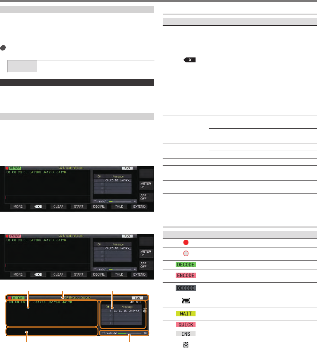
Frequency Offset when Shifting from SSB to CW Mode
Upon switching to the CW mode to communicate with a station that
transmitted a CW after the CW signal is received during operation
in the SSB mode, it is usually necessary to correct the frequency
by turning the Tuning control slightly. However, turning on this
function enables the frequency to be corrected automatically.
Configure in Menu [5-07] “Carrier Frequency Offset
(SSB Mode to CW Mode)”
Setting
Value Off (default)/ On
Encoding/Decoding Morse Code
Below are the steps to decode the RX signals of CW and display
them as character strings on the screen. Details of the transmitted
CW signals are also displayed as character strings.
Displaying the CW Communication Screen
1Set to the CW mode.
2Press F3 [DECODE] to display the CW
communication screen.
Decoding in Progress (Decodes and Displays the
Received Signal)
.
Encoding in Progress (Analyzes and Displays the
Transmission Code)
.
.
Threshold LevelTX Details
CW Message ListIndicator DisplaysTX/RX Details
Indicator Displays
Indicates the status of the function.
TX/RX Details
Displays the character strings that are transmitted or received.
TX Character String Buffer
Character strings to be transmitted.
CW Message List
Displays the fixed phrases that are registered in the CW message
memory. The number of channels displayed varies according to
the display screen size. (Standard: 4CH; Expanded: 8CH)
Threshold Level
Displays the threshold value of the RX signal strength for decoding.
Operating the CW Communication Screen
Key Behavior
F1 [MORE] Switches the key guide.
F2 [LOG] Turns ON/OFF the communication log function.
Pressing and holding this key displays the screen
for selecting a log file that is saved.
F2 [ ] Clears the characters inside the character string
buffer area one at a time. Pressing and holding
down the key clears the characters continuously.
F3 [PAUSE] Pauses update (drawing) of the TX/RX details
display area. Pressing the key again resumes the
update (drawing).
F3 [CLEAR]
Clears the character strings inside the character
string buffer area.
Pressing and holding down the key clears the
information inside the TX/RX details display area
all at once.
F4 [START]
F4 [STOP]
Starts encoding of the character strings in the
TX/RX details display area.
Stops encoding and returns to the decoding state.
F4 [QUICK] Turns ON/OFF the quick mode.
F5 [DEC.OFF]
F5 [DEC.ON]
Stops decoding.
Resumes the decode function.
F5 [DEC.FIL] Switches the decoding filter.
F6 [CW.MSG] Switches to the CW message screen.
F6 [CW.DEC] Switches to the CW communication screen.
F6 [THLD] Switches to the threshold level configuration
mode.
F7 [EXTEND] Enlarges the size of the CW communication
screen. Pressing it again restores the screen to the
standard size.
Indicator Displays
Display Behavior
.Appears when the log function is ON.
.
Appears when the log function is ON and in the
standby mode.
.Appears when signal decoding is in progress.
.
Appears when encoding the character strings in
the TX character string buffer.
.
Appears when the decode function is stopped or
disabled.
.
Appears when CW message is configured to the
repeat setting.
.
Appears during the repeat interval of the CW
message.
.Appears when the quick mode is ON.
.Appears when in the insert mode.
.
Appears when it is a count-up trigger message of
the contest number.
5 COMMUNICATING AIDS
5-10
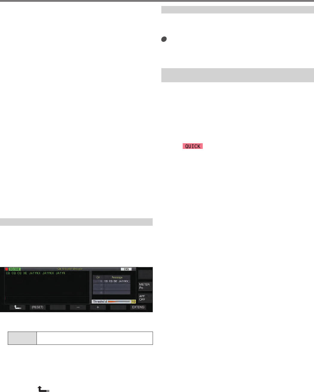
•Characters/character strings that are received or transmitted
are displayed in the “TX/RX details display area”.
•Eight code abbreviations are supported, namely BT, AR, AS,
HH, SK, KN, BK and SN.
•The code abbreviations are displayed in the “TX/RX details
display area” in the same way as normal character strings. For
example, when “AR” (code with no space between “A” and “R”)
is received, “AR” is displayed.
•The code abbreviations “KN”, “BT” and “AR” have the same
Morse code as the symbols “(”, “=” and “+” respectively. When
these Morse codes are received, they will be displayed as the
code abbreviations received. (Symbols are not displayed.)
•The “*” symbol has the same Morse code as the alphabet “X”.
When this Morse code is received, it will be displayed as the
alphabet “X” received.
•The codes might not be decoded correctly depending on the
signal quality.
•If the keying speed of the target signal changes halfway, the
characters immediately before or after the change cannot be
decoded correctly.
•Characters that cannot be decoded are indicated using an
underscore (_).
•Time stamp and frequency information can be added to the TX
or RX data that is displayed in the TX\RX details display area.
•This transceiver does not support Japanese characters.
•Press [Page Up] / [Page Down] on the USB keyboard to scroll
through the information displayed in the TX/RX details display
area.
•When encoding is started with the details of the past
transmission or reception displayed using [Page Up] on the
USB keyboard, the display moves automatically to the bottom
of the screen.
•Noise Reduction 1, Noise Reduction 2, audio peak filter and RX
DSP equalizer do not function during CW decoding.
Adjusting the Decode Threshold Level
The threshold value for the signal strength to activate decoding
can be adjusted as follows. Raising the threshold level may reduce
erroneous detection due to noise.
1Press F6 [THLD] to switch to the threshold level
configuration mode.
.
2Press F4 [–]/ F5 [+] or turn the [MULTI/CH] control
to select a threshold level.
Setting
Value 1 to 10 (default) to 30 (1-step)
•Adjust the threshold value in the ascending order according
to the receiving status of noise, for example. Start from a
small value between the range of 1 to 30 and configure the
threshold value to a point where reception is good.
•Pressing and holding F2 [(RESET)] resets the threshold
level to the default setting.
3Press F1 [ ] to end the process.
Decode Filter
A decode filter (narrow-band filter used exclusively for decoding)
can be used when there is significant interference or noise while
decoding the Morse code.
Press F5 [DEC.FIL].
Pressing F5 [DEC.FIL] each time switches the decode filter
mode (Off/Normal/ Narrow).
•The selected mode is displayed for about 2 seconds.
Transmitting Character Strings via USB Keyboard
Operation
Text input by the USB keyboard can be transmitted in Morse code.
1Connect the USB keyboard (commercially
available) to this transceiver.
2Press F3 [DECODE] to display the CW
communication screen.
3Press F4 [QUICK].
Press F4 [QUICK] each time toggles the quick mode between
ON and OFF.
•<< >> appears when the quick mode is ON.
4Select a frequency for communication.
5Enter a character string using the USB keyboard.
When Quick Mode is ON:
After characters are input using the USB keyboard, a “TX
details display area” is displayed and encoding starts
immediately.
When Quick Mode is OFF:
After characters are input using the USB keyboard, they are
displayed in the “TX details display area”. To start encoding,
press [Enter] on the USB keyboard or the F4 [START] key.
•Sending a character string using the USB keyboard while the
update (drawing) of TX/RX display area is paused cancels the
paused state.
•The maximum number of characters that can be entered in the
TX details display area is 4300 characters.
•The consecutive code (code abbreviation) applies to the
characters after inputting “~” (tilde) and continues until there is
a space between the characters.
•For example, when “~ HH” and “~ OSO” are input, they denote
a correction code and emergency communication respectively.
•To start encoding from a consecutive code while quick mode is
ON, input the first character of the consecutive code within the
time interval equivalent to 7 dots (space between words) after
inputting “~” (tilde).
COMMUNICATING AIDS 5
5-11
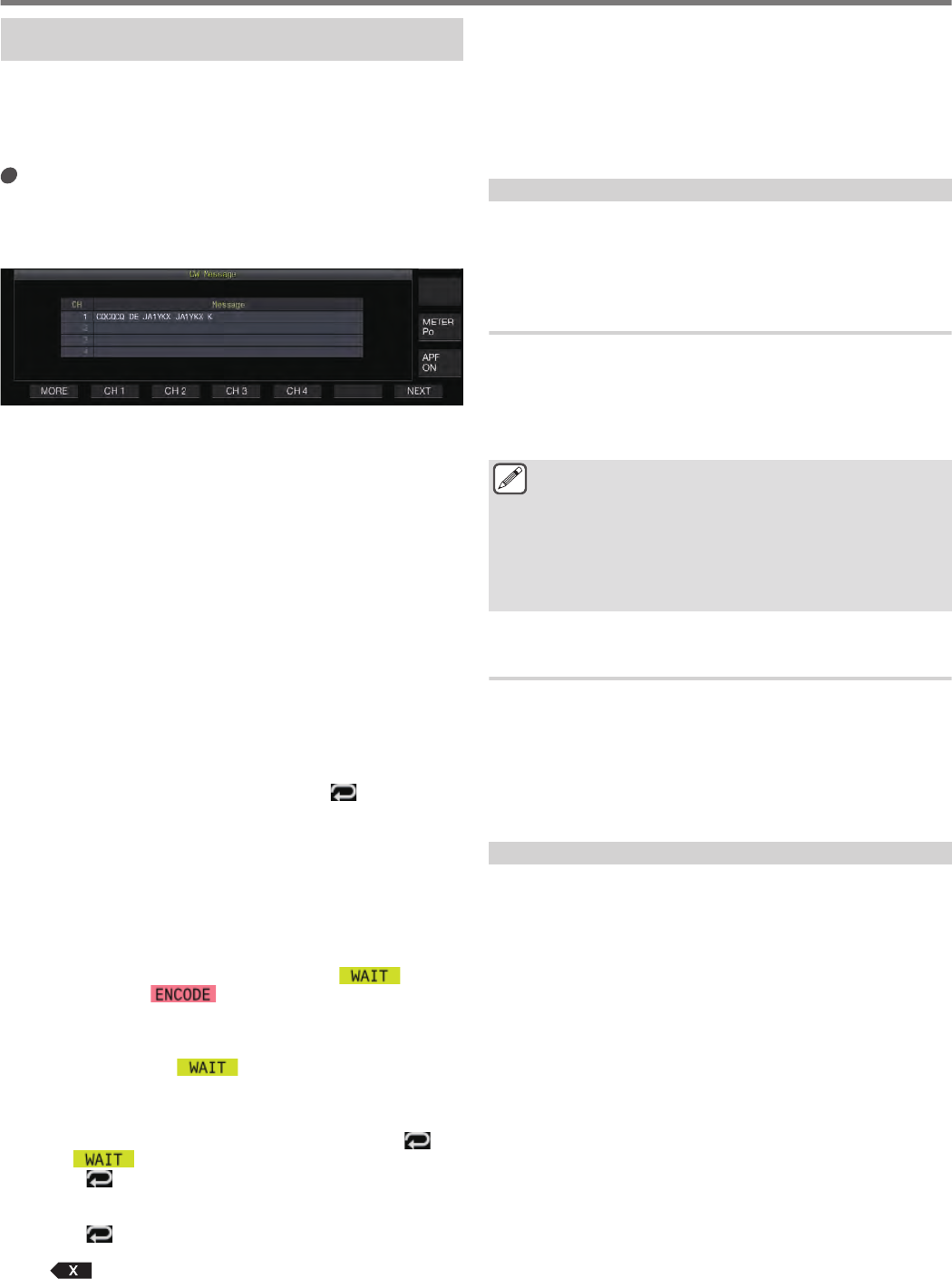
Encoding Character Strings Using the CW Message
Memory
Fixed phrases can be registered in the CW message memory for
use during transmission.
•Use the CW message memory when transmitting a fixed
phrase. Otherwise, the USB keyboard can also be used to input
the character string.
Press F2 [CH 1] to F5 [CH 4].
The phrase registered in the corresponding message channel
is displayed in the “TX details display area” and encoding starts
immediately.
•The registration number is “x”.
.
•If a character string already exists in the “TX details display
area”, encoding starts after the fixed phrase is added to the
end of the character string.
•If encoding of a character string is already in progress, the
fixed phrase is added to the end of the character string and
encoding will continue.
•A space is inserted before the fixed phrase when it is added
to the end of an existing character string.
•Message CH supports only messages registered via text
input. (Even when “Paddle” is selected for registering
messages in the menu, the message CH information
registered via text input using the USB keyboard is displayed
on the CW communication screen.)
•If the message displayed in the message list is too long to fit
into the display range, this will be indicated by a “...” display
to the right of the truncated message.
Encoding Operation of Message Channel with Repeat
Function Enabled
•Upon pressing the key that corresponds to a message channel
for which the repeat function is enabled, << >> lights up.
•After encoding of the character strings in the “TX details display
area” is complete, the transceiver switches to the “repeat wait”
mode. After the specified time interval has elapsed, the same
character strings of the channel for which the repeat function is
enabled is encoded again, and this process goes on.
•After encoding of the information in the “TX details display area”
is fully complete, all the information in the area is cleared. Only
the character string of the repeat channel is displayed in white
fonts, and the transceiver switches to the “repeat wait ”mode.
•Upon switching to the “repeat wait” mode, << >> lights
up, after which << >> is illuminated. (These will light
up in the grayed-out state when the decoding function is
stopped.)
•When the specified time interval after entering the “repeat wait”
state has elapsed, << >> disappears and encode
operation resumes.
•Pressing F4 [STOP] or [ESC] on the USB keyboard stops the
encoding operation or “repeat wait” state and returns the
transceiver to the decoding state. (The light for the << >>
and << >> displays go off.)
•While << >> is illuminated, character strings cannot be
added using the USB keyboard or the F2 [CH 1] to F5 [CH 4]
keys.
•While << >> is illuminated, characters cannot be deleted
using the backspace key of the USB keyboard or the
F2 [] key.
Contest Number Behavior
•To use a contest number, “%N” needs to be embedded in the
message of the message channel.
•The “%N” portion will be substituted with the current contest
number during encoding.
•The contest number is counted up after all the contents in the
“character string buffer area” are encoded.
Paddle Operation on CW Communication Screen
Morse code that is input via paddle operation (straight key, bug
key, etc.) can be converted into text and displayed on the screen.
This function can also be used to practice the input of Morse code.
Paddle Operation when the TX Details Display Area
is Empty
•When break-in is ON, the Morse code input is transmitted and
information that is keyed is displayed in the TX details display
area character by character.
•When break-in is OFF, the Morse code input is not transmitted
and information that is keyed is displayed in the character string
buffer area character by character.
●Encoding does not start even when the quick mode is
set to ON.
●Encoding does not start even when characters are
added using the USB keyboard after the character
strings that are added via paddle operation.
●To enable encoding of the character strings displayed in
the character string buffer area, press F4 [START] or
[Enter] on the USB keyboard.
Paddle Operation during Encoding of Character
Strings in the TX Details Display Area
•When Interrupt Keying is ON, encoding of character strings is
temporarily stopped and resumes only after keying is complete.
•When Interrupt Keying is OFF, encoding of character strings is
stopped.
•If the signals input via paddle operation are codes that cannot
be converted into text, the characters are not added to both the
“TX details display area” and “TX/RX details display area”.
Saving CW Communication Logs
The CW, RTTY and PSK communication screens can be saved
using the communication log function. Please refer to
“Communication Log” on page 5-27.
5 COMMUNICATING AIDS
5-12
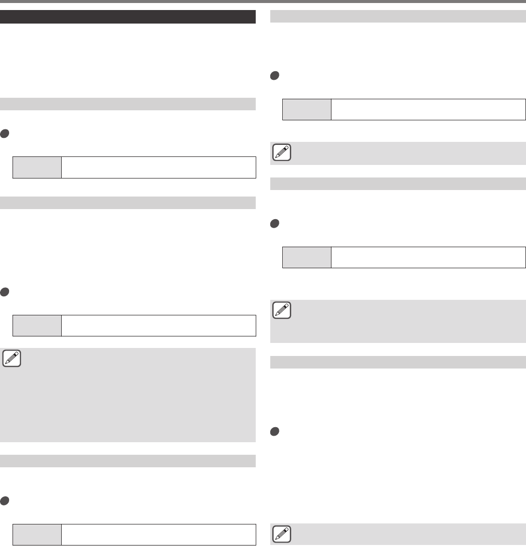
Electronic Keyer
This transceiver comes with a built-in electronic keyer that can be
used simply by connecting a paddle to the PADDLE jack on the
front panel. Depending on the settings, it can also be used as a
bug key (semi-auto electronic keyer).
•A straight key can also be connected to the PADDLE jack.
Selecting the PADDLE Jack Behavior
Select the device to be connected to the PADDLE jack.
Configure the behavior in Menu [5-00] “Paddle Jack
Configuration (Front)”
Setting
Value Straight Key/ Paddle (default)/ Paddle (Bug Key Mode)
Selecting the KEY Jack Behavior
For operation in the CW mode without using the built-in electronic
keyer, connect the plug of a straight key, bug key, external
electronic keyer or PC keyer to the “KEY” jack. The built-in
electronic keyer can also be used by connecting a paddle to the
“KEY” jack.
Select the device to be connected to the “KEY” jack on the rear
panel.
Configure in Menu [5-01] “Key Jack Configuration
(Rear)”
Setting
Value Straight Key (default)/ Paddle/ Paddle (Bug Key Mode)
●Connect a PC keyer or an external electronic keyer with
a positive-polarity wire using a shield wire.
●Behavior when Paddle (Bug Key Mode) is selected
•While dots are combined according to the usual
keyer, dashes are keyed while the paddle is pressed.
•The keying speed is variable, but the message
memory function does not work.
●When both dot and dash are configured to ON at the
same time, priority is given to dash.
Operation Mode of the Electronic Keyer
2 operation modes of the built-in electronic keyer are available for
selection (A or B).
Configure in Menu [5-02] “Electronic Keyer
Squeeze Mode”
Setting
Value Mode A/ Mode B (default)
Mode A: When both paddles are open, code transmission ends
after the code elements (dot or dash) are transmitted. Both dot
and dash memory are not active.
Mode B: When both paddles are open, code transmission ends
after a dash (or dot) is transmitted following the dot (or dash)
that is currently being transmitted. Both dot and dash memory
are active.
Reversing Dot and Dash
It is possible to reverse dot and dash of the paddle without having
to rewire the electronic keyer. Reversing the position for operating
the paddle according to the operator’s preferences or dominant
hand helps to ease keying.
Configure in Menu [5-03] “Dot and Dash Reversed
Keying”
Setting
Value Off (default)/ On
•Dot and dash is reversed when this function is set to “On”.
●This setting applies to both the mic paddle mode and
paddle that is connected to the PADDLE or KEY jack.
Mic Paddle Mode
The [UP] and [DOWN] keys of the microphone is used in place of
the paddle for keying.
Configure in Menu [5-04] “Paddle (Microphone Up/
Down Keys)”
Setting
Value Off (default)/ On
•When this is “On”, keying can be performed using the [UP]
and [DOWN] keys of the microphone.
●Response will be slower in the mic paddle mode
compared to the normal paddle operation.
●In the default setting, the [DOWN] key is assigned with
dot and the [UP] key with dash.
Adjusting the Keying Speed
The keying speed of the electronic keyer can be adjusted freely.
To ensure that CW is transmitted precisely, it is necessary to adjust
the keying speed according to the skill level of the user. Also, it is
recommended that the keying speed be as closely aligned as
possible with the CW speed of the target station.
Turn the [KEY] control to adjust the keying speed.
The keying speed can be adjusted within the range of 4 to 60
[wpm] (20 to 300 characters/minute).
•Turning the [KEY] control to the right increases the keying
speed, while turning the control to the left slows it down.
•The keying speed is displayed while the [KEY] control is
being operated.
•After operating the [KEY] control, the TX output power
display shows the keying speed for a duration of 2 seconds.
●Only dots are supported in the bug key mode.
COMMUNICATING AIDS 5
5-13
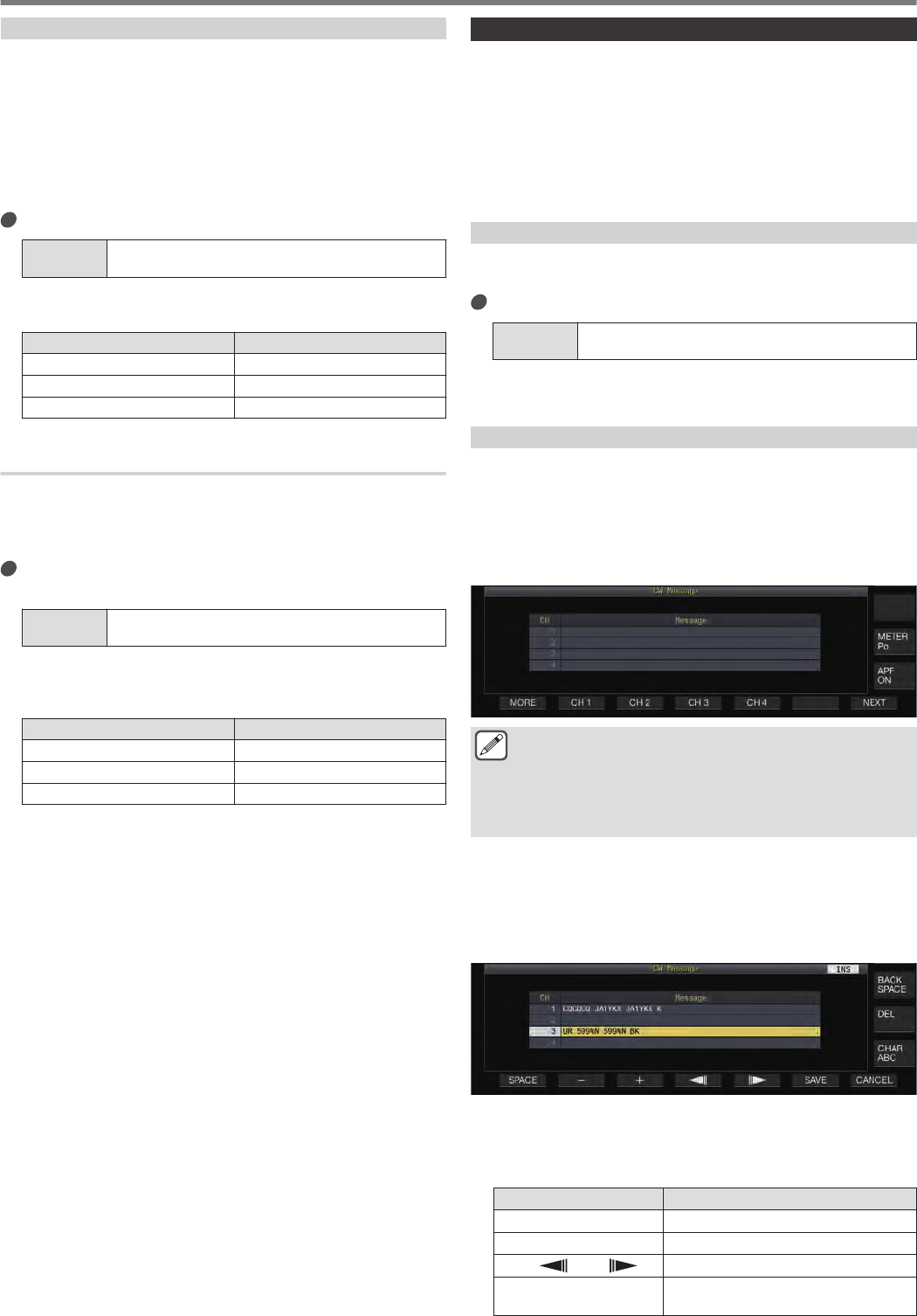
Changing the Weighting
The electronic keyer allows the dot-dash weighting to be adjusted
automatically. Weighting is the ratio of the dash length to the dot
length.
•2 weighting modes are available for selection: the “auto
weighting” mode changes the ratio automatically in tandem with
the keying speed, while the ratio is fixed in the “manual
weighting” mode and not affected by the keying speed.
•When [2.5] (1:2.5) to [4.0] (1:4) is selected, the dot-dash weight
ratio is fixed regardless of the keying speed.
Configure in Menu [5-08] “CW Keying Weight Ratio”
Setting
Value Automatic (default)/ 2.5 to 4.0 (0.1 step)
•When this is configured to “Automatic”, the keying speed and
weight ratio settings are as follows.
Adjusting the Keying Speed Weight
4 to 24 1:2.8
25 to 44 1:3.0
45 to 60 1:3.2
Weight Ratio Reverse
When the weighting mode is configured to “Automatic”, increasing
the keying speed increases the weight ratio. Configuring the menu
below to ON decreases the weight ratio when the keying speed
increases.
Configure in Menu [5-09] “CW Keying Reversed
Weight Ratio”
Setting
Value Off (default)/ On
•When weight reverse is enabled in the “Automatic” weighting
mode, the keying speed and weight ratio settings are as
follows.
Adjusting the Keying Speed Weight
4 to 24 1:3.2
25 to 44 1:3.0
45 to 60 1:2.8
CW Message Memory
This transceiver comes with memory channels that can store up
to 8 CW messages. In addition to paddle operation, a message
can be registered by entering a text using the USB keyboard or via
operating this transceiver.
•CW message memory channels come in handy for messages
that are repeatedly transmitted as registering the messages in
advance allows them to be used repeatedly such as during
contest.
Switching the Method of Registering CW Messages
A method for registering messages can be selected from the
options below.
Configure in Menu [5-11] “CW Message Entry”
Setting
Value Text String/ Paddle (default)
Text String: Registers messages using text strings.
Paddle: Registers messages via paddle operation.
Registering CW Messages via Text Input
Check to ensure that the CW message registration method in
Menu [5-11] is configured to “Text String”, followed by performing
the steps below to register a CW message. CW messages can be
stored in any of the channels from 1 to 8.
1Press F2 [KEYER] to display the CW Message
screen (for text input).
.
●When this transceiver is in a mode other than CW, F2
[KEYER] is not displayed in the key guide. Press
[CW/CW-R].
●If the channel to register the CW message is not
displayed in the key guide, press F1 [MORE]. Doing so
switches the key guide.
2Press and hold F2 [CH 1] to F5 [CH 4] or F2 [CH 5]
to F5 [CH 8] to select the channel to register the CW
message.
The CW message edit screen is displayed.
•Pressing F7 [NEXT] each time switches between F2 [CH
1] to F5 [CH 4] and F2 [CH 5] to F5 [CH 8].
.
3Use the function keys, [MULTI/CH] control or USB
keyboard to enter a CW message.
•Enter a message that contains not more than 50 characters.
The default setting is blank.
Key Behavior
F1 [SPACE] Inserts a space.
F2 [–]/ F3 [+] Selects a character.
F4 [ ]/ F5 [ ] Moves the cursor.
F [BACK SPACE] Deletes the character to the left of the
cursor.
5 COMMUNICATING AIDS
5-14
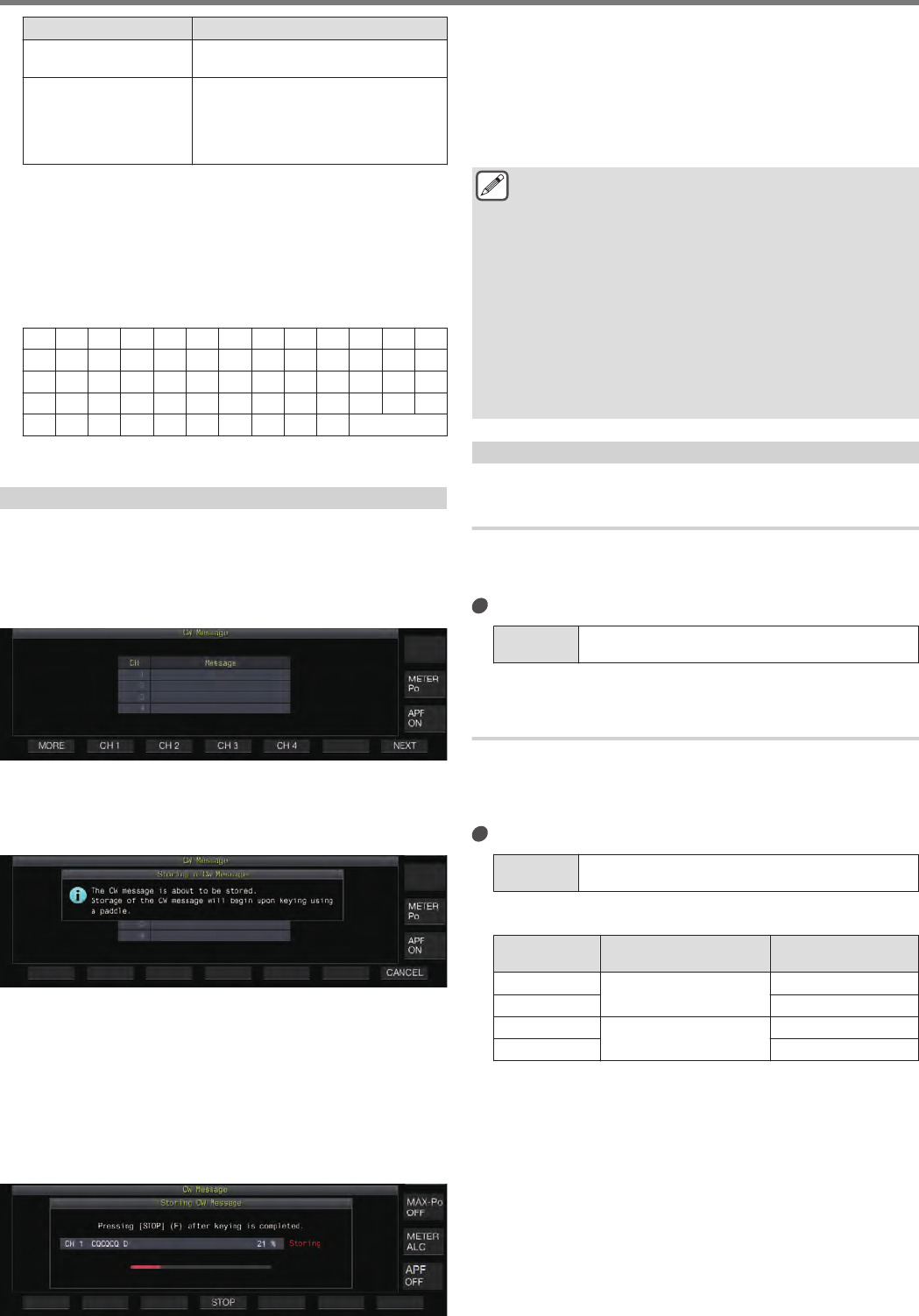
Key Behavior
F [DEL] Deletes the character to the right of the
cursor.
F [CHAR]
Switches the type of character to edit.
Pressing the key each time switches the
selection in the following sequence:
ABC (upper case) → !”# (symbols) →
ABC (upper case)
•Pressing F7 [CANCEL] returns the display to the CW
message screen without registering the input message.
•When “%N” is saved as part of a CW message, this will be
substituted with a contest number during transmission.
•A continuous text string that is input after “~” and up to that
before an inserted space becomes a consecutive code such
as AR or BT.
•Characters that can be input are as follows.
A B C D E F G H I J K L M
N O P Q R S T U V W X Y Z
0123456789
/ ? . , ‘ ( ) : = + - _ "
@ ~ % < > Space
4Press F6 [SAVE] to save the CW message.
Registering CW Messages via Paddle Operation
Check to ensure that the CW message registration method in
Menu [5-11] is configured to “Paddle”, followed by performing the
steps below to register a CW message. CW messages can be
stored in any of the channels from 1 to 8.
1Press F2 [KEYER] to display the CW Message screen.
.
2Press and hold F2 [CH 1] to F5 [CH 4] or F2 [CH 5]
to F5 [CH 8] to select the channel to register the CW
message.
A message prompting registration of a CW message is displayed.
.
•While in the input standby mode, pressing F7 [CANCEL]
returns the display to the CW message screen without
registering the message.
3Register a CW message via keying with a paddle.
When keying using a paddle starts, the display switches to a
CW message (paddle) registration screen. Continuing keying
in this state registers the CW message. During registration of
a CW message, memory usage (%) is displayed on the screen.
•If paddle operation is not performed during the registration process,
a space will be inserted at every interval equivalent to 7 dots.
.
4Press F6 [STOP] to end registration of the CW
message.
•The display returns to the CW Message screen.
•If the memory is used up (indicated as 100%), the CW
message registration process ends automatically even
when it is still in progress.
•Morse code that is input is converted into text strings and
displayed in the channel list of the CW Message screen.
●For channels that do not contain any CW message, the
corresponding channel numbers are displayed in gray.
●CW messages cannot be registered if the PADDLE or
KEY jack is not configured to the PADDLE mode.
Operate the paddle to register a CW message.
●The Morse code displayed in the channel list uses the
same functions as “Morse code decoding”. For this
reason, the spacing may be wider or different characters
may be displayed depending on the habit and the speed
of the operator performing the keying.
●The “*” symbol and code abbreviations are also
displayed in the same way as “Morse code decoding”.
●Japanese texts can be registered but will not be
displayed correctly.
Contest Number
Configuring the Starting Contest Number (Text Input
Only)
The starting contest number can be configured when the contest
numbers are 3-digit serial numbers that run from 001 (001
method).
Configure in Menu [5-12] “Contest Number”
Setting
Value 001 (default) to 9999 (1 step)
Selecting a Method for Sending out Contest Number
(Text Input Only)
When a CW message that contains a “%N” input is transmitted,
numeric values “1”, “9” and “0” are converted into alphabets “A”,
“N” and “O” (or “T”) respectively in the Morse code format and sent
out as a contest number.
Configure in Menu [5-13] “Contest Number Format”
Setting
Value Off (default)/ 190 to ANO/ 190 to ANT/ 90 to NO/ 90 to
NT
Coding Example
Option Text String Sent out as
Contest Number Output Code
190 to ANO 190 ANO
(•‒‒•‒‒‒)
190 to ANT ANT
(•‒‒•‒)
90 to NO 90 NO
(‒•‒‒‒)
90 to NT NT
(‒•‒)
COMMUNICATING AIDS 5
5-15
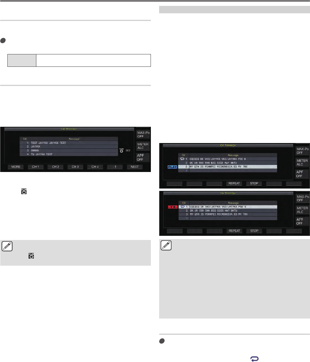
Selecting a Channel for Counting up the Contest
Numbers (Text Input Only)
The CW message channel for which contest numbers are counted
up can be registered using this setting.
Configure in Menu [5-14] “Channel Number (Count-
up Message)”
Setting
Value Off (default)/ Channel 1 to Channel 8
Decrementing the Contest Number (Text Input Only)
If communication is not established after a contest number is sent
to the receiving station, the contest number that is sent next will be
decremented (reduced) by 1.
1Press F2 [KEYER] to display the CW Message
screen.
.
2Press F7 [NEXT] to select a channel group for which
the contest numbers are to be displayed.
•<< >> is displayed beside the channel for counting up the
contest number, and F6 [-1] is displayed in the key guide.
•Pressing F7 [NEXT] each time switches between F2 [CH
1] to F5 [CH 4] and F2 [CH 5] to F5 [CH 8].
•For more details on the method for selecting a channel
group, please refer to “Registering CW Messages via Text
Input”.
3Press F6 [-1] to reduce the contest number by 1.
●When the setting of the channel for counting up the
contest number in Menu [5-14] is configured to “Off”,
<< >> is not displayed and F6 [-1] is also not shown
in the key guide.
Playing/Transmitting CW Messages
This transceiver can be configured as follows to play back or
transmit a registered CW message. The CW message screen and
function key displays are different when Menu [5-11] “CW
Message Entry” is configured to “Paddle” and when it is configured
to “Text String”. Descriptions in this manual are based on the
“Paddle” setting, but the steps are the same when it is configured
to “Text String”. Also, a CW message needs to be registered in
advance before it can be played back or transmitted.
1Press F2 [KEYER] to display the CW Message
screen.
2To play back a CW message, press [VOX] to set
break-in to OFF.
•When break-in is set to OFF, the [VOX] LED light goes off.
•To transmit a CW message, set break-in to ON. When break-
in is set to ON, the [VOX] LED lights up.
3Press F2 [CH 1] to F5 [CH 4] or F2 [CH 5] to F5 [CH
8] to select a CW message.
•Playback or transmission starts. To cancel the operation,
press F5 [STOP].
.
●When Menu [5-14] “Channel Number (Count-up
Message)” is configured to a setting other than “Off”, the
contest number is added immediately after playback or
transmission of the CW message for the selected
channel has ended.
●Operating the paddle while Menu [5-10] “Interrupt
Keying” is “On” pauses playback or transmission of the
message memory. After paddle operation has ended,
playback or transmission resumes from the paused
state. Operating the paddle while “Off” is configured
stops playback or transmission of the message memory.
●To transmit a CW message without using break-in, press
[SEND] instead of performing step 2.
Repeat Playback of CW Messages
Press F4 [REPEAT].
Pressing F4 [REPEAT] each time toggles the repeat function
between ON and OFF.
•When the repeat mode is ON, << >> lights up for the
selected CW message memory.
5 COMMUNICATING AIDS
5-16
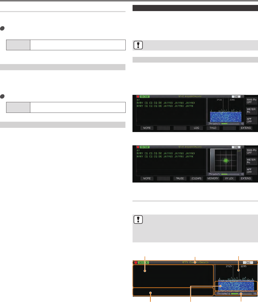
Configuring the Repeat Playback Interval
The time interval for repeating playback of a CW message can be
configured.
Configure in Menu [5-16] “CW/Voice Message
Retransmit Interval Time”
Setting
Value 0 to 10 (default) to 60 [s] (1 step)
Configuring to a larger value lengthens the playback interval.
Interrupt Keying
Operating the paddle while playback or transmission of a CW
message is in progress allows the CW message playback or
transmission process to be interrupted for the Morse code input
using the paddle to be inserted.
Configure in Menu [5-10] “Interrupt Keying”
Setting
Value Off (default)/ On
Deleting a CW Message
The steps to delete a CW message that is registered in Channel 1
to Channel 8 are as follows.
1Press F2 [KEYER] to display the CW Message
screen.
2Select a channel number that contains the CW
message to delete.
3Press and hold F5 [(DELETE)] to delete the CW
message.
RTTY Operation
This transceiver comes with a built-in demodulator for RTTY
operation, a RX decoder and a TX encoder. It is possible to operate
in RTTY (FSK) independently by combining the use of a
commercially available USB keyboard. Also, it is possible to
operate in the RTTY mode by connecting an external device.
●Before operating in the RTTY mode, adjust the carrier
level while checking the ALC meter.
Displaying the RTTY Communication Screen
1Press [FSK/PSK] to select RTTY (FSK) mode.
2Press F3 [DECODE].
The RTTY communication screen appears.
Text Display Area + FFT Scope
.
Text Display Area + X-Y Scope
.
Switching between the FFT Scope and X-Y Scope
Display
The display toggles between the audio FFT scope and X-Y scope
each time the scope display is touched.
●The RTTY communication screen will not be displayed
if Menu [2-06] “FSK Spacing” is not configured to “170
[Hz]”.
●Noise Reduction 1, Noise Reduction 2, Beat Canceler 1,
Beat Canceler 2, audio peak filter and RX DSP equalizer
do not function during decoding of RTTY messages.
The layout of the RTTY communication screen is as follows.
.
Threshold Level
WaterfallTX Details
FFT ScopeIndicator DisplaysTX/RX Details
Indicator Displays
Indicates the status of the function.
TX/RX Details
Displays the character strings that are transmitted or received.
TX Details
Character strings to be transmitted.
COMMUNICATING AIDS 5
5-17
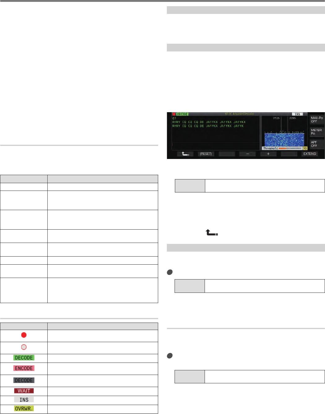
FFT Scope
The audio FFT scope is used for viewing the tuning status.
The two vertical lines on the left and right represent the mark and
space frequencies respectively. Adjust the tuning frequency while
receiving a signal such that the two peaks overlap evenly with the
two lines.
Waterfall
The waterfall is a time-series display of the RX signal spectrum
which functions in tandem with the FFT scope. The entire waterfall
display can also be shifted in tandem with changes in the RX
frequency.
X-Y Scope
The X-Y scope displays the tuning status in the RTTY (FSK) mode
as a cross pattern. The cross patterns bisect at right angles (90
degrees) when this transceiver is correctly tuned to the signal.
Threshold Level
Displays the threshold value of the RX signal level for decoding.
Operating the RTTY Encode/Decode Screen
The following operations are enabled when the RTTY
communication screen opens.
•Pressing the [Page Up] or [Page Down] key scrolls the display
of the TX or RX details.
Key Behavior
F1 [MORE] Switches the key guide.
F3 [PAUSE]
Pauses update (drawing) of the TX/RX details
display area. Pressing the key again resumes the
update (drawing).
F4 [LOG]
Turns ON/OFF the communication log function.
Pressing and holding this key displays the screen
for selecting a log file that is saved.
F4 [(CLEAR)] Pressing and holding the key clears the text
displayed on the TX/RX details screen.
F5 [THLD] Switches to the threshold level configuration
mode.
F5 [MEMORY] Switches to the RTTY Message screen.
F6 [X-Y LEV] Switches between the speed and density of the X-
Y scope.
F7 [EXTEND]
Enlarges the size of the RTTY communication
screen.
Pressing it again restores the screen to the
standard size.
Indicator Displays
Display Behavior
.
Appears when the communication log function is
ON.
.
Appears when the communication log function is
ON and in the standby mode.
.Appears when signal decoding is in progress.
.
Appears when encoding the characters in the TX
buffer.
.
Appears when the decode function is stopped or
disabled.
.Appears when transmitting the message memory.
.Appears when in the insert mode.
.Appears when in the overwrite mode.
Saving RTTY Communication Logs
The CW, RTTY and PSK communication screens can be saved
using the communication log function. Please refer to
“Communication Log” on page 5-27.
Adjusting the RTTY Decode Threshold Level
Noise that occurs when there is no signal may sometimes be
erroneously detected as text, which results in the display of
unwanted text. To reduce the occurrence of such issues, adjust
the threshold level.
•Raise the threshold level when there is frequent erroneous
detection due to noise.
1Press F5 [THLD].
The threshold level setting can now be adjusted.
.
2Press F4 [–]/ F5 [+] or turn the [MULTI/CH] control
to adjust the level.
Setting
Value 1 to 10 (default) to 30 (1 step)
•Adjust the threshold value in the ascending order according
to the receiving status of noise, for example. Start from a
small value between the range of 1 to 30 and configure the
threshold value to a point where reception is good.
•To restore the default setting, press and hold F2 [(RESET)].
3Press F1 [ ] to end the process.
FFT Scope/X-Y Scope Display Setting
The tuning scope displayed on the RTTY communication screen
can be switched to an “FFT scope” or “X-Y scope” display.
Configure in Menu [2-09] “RTTY Tuning Scope”
Setting
Value FFT Scope (default)/ X-Y Scope
•The display toggles between the “FFT Scope” and “X-Y Scope”
each time the scope display on the screen is touched.
FFT Scope Waveform Averaging
The waveform displayed on the FFT scope can be averaged.
Averaging of the waveform reduces random noise and makes
observation of the target signal easier.
Configure in Menu [2-00] “FFT Scope Averaging
(RTTY Decode)”
Setting
Value 0 (default) to 9 (1 step) (minimum to maximum
averaging)
5 COMMUNICATING AIDS
5-18
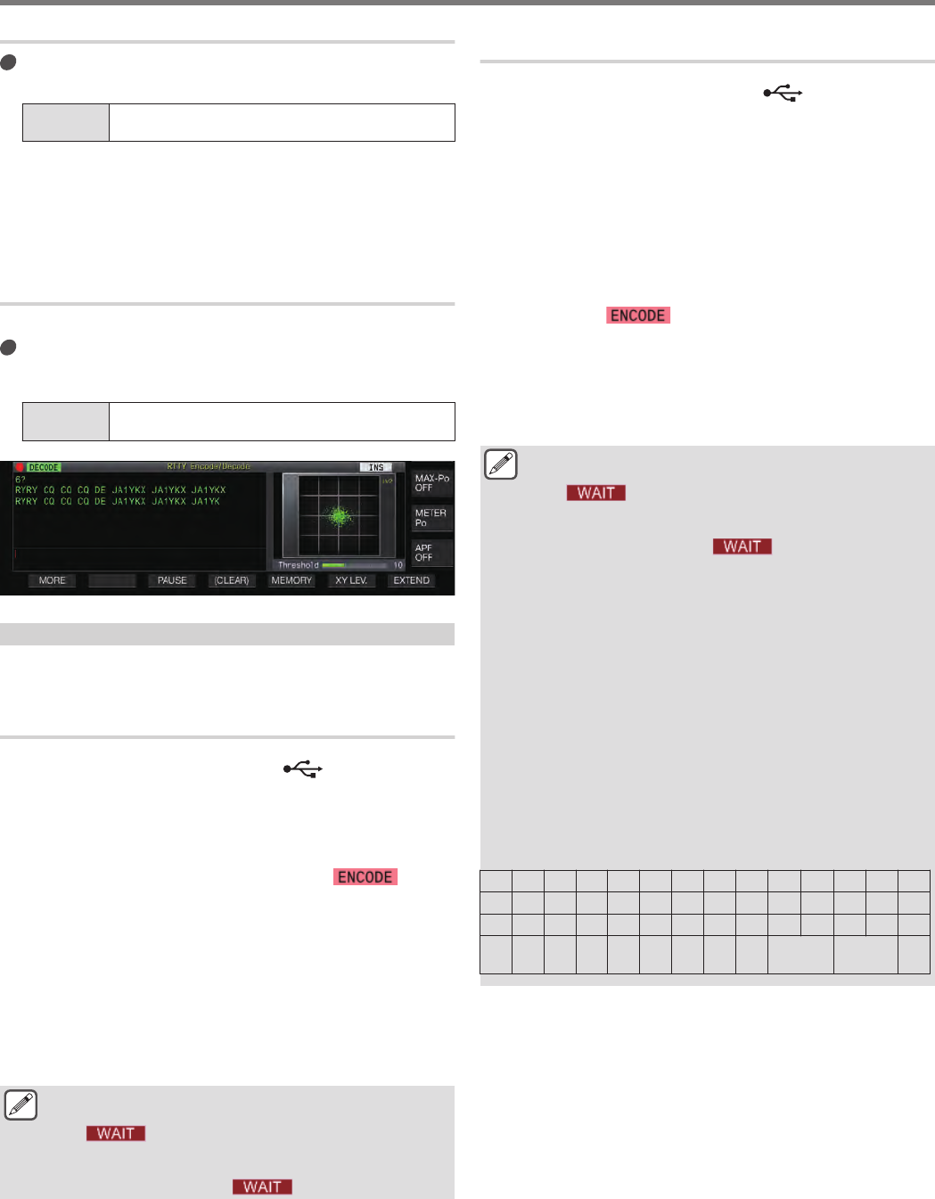
Selecting a Waterfall Display Type
Configure in Menu [2-17] “Waterfall when Tuning
(RTTY/PSK Audio Scope)”
Setting
Value Straight (default)/ Follow
Straight: Uses a straight line to show transition in the level of
the target signal displayed on the waterfall when the RX
frequency is altered.
Follow: Tracks and displays the latest audio FFT level at the
portion where the waterfall starts flowing when the RX
frequency is altered.
Tracking Speed/Density Level of X-Y Scope
Switch between the speed and density of the X-Y scope.
Press F6 [XY LEV.].
Pressing F6 [XY LEV.] each time switches the level. The
tracking speed is displayed on the X-Y scope display.
Setting
Value Lv1/ Lv2 (default)/ Lv3
.
Transmitting Character Strings Using USB Keyboard
A commercially available USB keyboard can be used to input and
transmit character strings.
Transmitting the Input Character String Immediately
1Connect the USB keyboard to (USB-A).
2Press F3 [DECODE] to display the RTTY
communication screen.
3Press [F12] on the USB keyboard to enter the TX
mode.
The [BUSY/TX] LED lights up in red, and << >> is
displayed in the status bar.
4Enter a character string using the USB keyboard.
•The input character string is displayed in the TX details
display area and transmitted immediately.
•In the TX details display area, the color of the individual
characters change successively once they are transmitted.
•Characters that have been transmitted appear successively
in the TX/RX details display area.
5Press [F12] on the USB keyboard to end
transmission.
●If there remain characters in the TX details display area
that are not transmitted when [F12] is pressed in step 5,
<< >> is displayed in the status bar. After
transmission of all the character strings is complete, the
transceiver switches to the RX mode and the light of the
[BUSY/TX] LED and << >> display go off.
Temporarily Placing Character Strings in the TX
Details Display Area before Transmission
1Connect the USB keyboard to (USB-A).
2Press F3 [DECODE] to display the RTTY
communication screen.
3Enter a character string using the USB keyboard.
The input character string is displayed and temporarily placed
in the TX details display area.
4Press [F12] on the USB keyboard to send out the
character string.
•Character strings that are stored in the TX details display
area are sent out by this transceiver.
•Upon entering the TX mode, the [BUSY/TX] LED lights up in
red, and << >> is displayed in the status bar.
•In the TX details display area, the color of the individual
characters change successively once they are transmitted.
Character strings that have been transmitted appear
successively in the TX/RX details display area.
5Press [F12] on the USB keyboard to end
transmission.
●If there remain characters in the TX details display area
that are not transmitted when [F12] is pressed in step 5,
<< >> is displayed in the status bar. After
transmission of all the character strings is complete, the
transceiver switches to the RX mode and the light of the
[BUSY/TX] LED and << >> display go off.
●Pressing [ESC] while transmission of the character
strings is in progress switches this transceiver to the RX
mode. Transmission of the character strings stops, and
character strings in the character string buffer that are
not yet transmitted are cleared.
●Time stamp and frequency information can be added to
the TX or RX data that is displayed in the TX details
display area. Refer to “Displaying a Time Stamp”
(5-28).
●Sending a character string using the USB keyboard
while the TX/RX display is paused by pressing F3
[PAUSE] cancels the paused state.
●The character strings that can be placed temporarily in
the TX details display area can contain a maximum of
4300 characters.
●Alphanumeric characters and symbols that can be input
using a USB keyboard are as follows.
A B C D E F G H I J K L M N
O P Q R S T U V W X Y Z 0 1
2 3 4 5 6 7 8 9 ! “ # $ & ’
( ) . , - ? : ; /
Space
Line
Break
COMMUNICATING AIDS 5
5-19
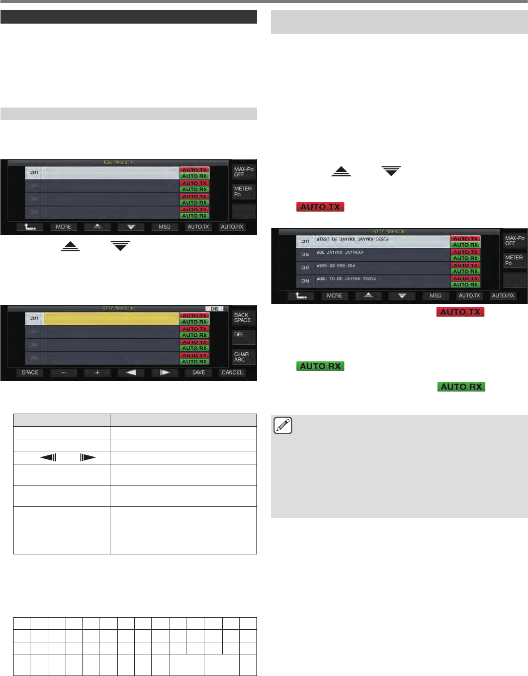
RTTY Message Memory
Fixed phrases that are often used in the RTTY mode can be
registered in advance as an RTTY message in the RTTY message
memory. Configuring a message to be saved to auto transmission
(Auto TX) or auto reception (Auto RX) enables the RTTY message
to be transmitted via simple operation. Up to 8 types of RTTY
messages can be registered to Channels 1 to 8 in the memory.
Registering RTTY Messages
1Press F5 [MEMORY] on the RTTY communication
screen to display the RTTY Message screen.
.
2Press F3[ ] / F4[ ] or turn the [MULTI/CH]
control to select the channel for saving the RTTY
message.
3Press F5 [MSG] to enter the RTTY message memory
edit mode.
.
4Use the function keys, [MULTI/CH] control or USB
keyboard to enter a character string.
Key Behavior
F1 [SPACE] Inserts a space.
F2 [–]/ F3 [+] Selects a character.
F4 [ ]/ F5 [ ] Moves the cursor.
F [BACK SPACE] Deletes the character to the left of the
cursor.
F [DEL] Deletes the character to the right of the
cursor.
F [CHAR]
Switches the type of character to edit.
Pressing the key each time switches the
selection in the following sequence:
ABC (upper case) → !”# (symbols) →
ABC (upper case)
5Press F6 [SAVE] to save the RTTY message.
•Pressing F7 [CANCEL] discards the content that is currently
being edited and exits the character string input mode.
•Alphanumeric characters and symbols that can be input (up
to 70 characters)
A B C D E F G H I J K L M N
O P Q R S T U V W X Y Z 0 1
2 3 4 5 6 7 8 9 ! “ # $ & ’
( ) . , - ? : ; /
Space
Line
Break
Configuring Auto TX/RX for the RTTY Message
Memory
The transmission and reception behavior can be configured when
an RTTY message memory channel is selected.
•Auto TX places this transceiver in the TX mode before
transmitting a message when a message memory channel is
selected, and maintain the TX mode after all messages have
been sent out.
•For auto RX, pressing [F12] after selecting a message memory
channel for transmission places this transceiver in the TX mode.
When the message is sent out, this transceiver is automatically
restored to the RX mode.
•Combining auto TX and auto RX enables both transmission and
reception to be performed automatically.
1Press F3[ ] / F4[ ] or turn the [MULTI/CH]
control to select the message for auto TX/RX.
2Press F6 [AUTO.TX] to set auto TX to ON.
<< >> is displayed to the right of the RTTY
message.
.
•When auto TX is set to OFF, the << >> display
goes off, and the RTTY message of the channel is
temporarily placed in the character string buffer but not
transmitted automatically.
3Press F7 [AUTO.RX] to set auto RX to ON.
<< >> is displayed to the right of the RTTY
message.
•When auto RX is set to OFF, the << >> display
goes off, and this transceiver is not restored to the RX mode
after the RTTY message for the channel has been sent out.
●To sent an RTTY message for which “AUTO TX” is
configured to “OFF”, select the channel in which the
RTTY message is stored. Check to ensure that the
character string (RTTY message) is forwarded to the
character string buffer, followed by pressing [F12] on the
USB keyboard.
●To switch this transceiver to the RX mode after
transmitting an RTTY message for which “AUTO RX” is
set to OFF, press [F12] on the USB keyboard after the
RTTY message has been sent out.
5 COMMUNICATING AIDS
5-20
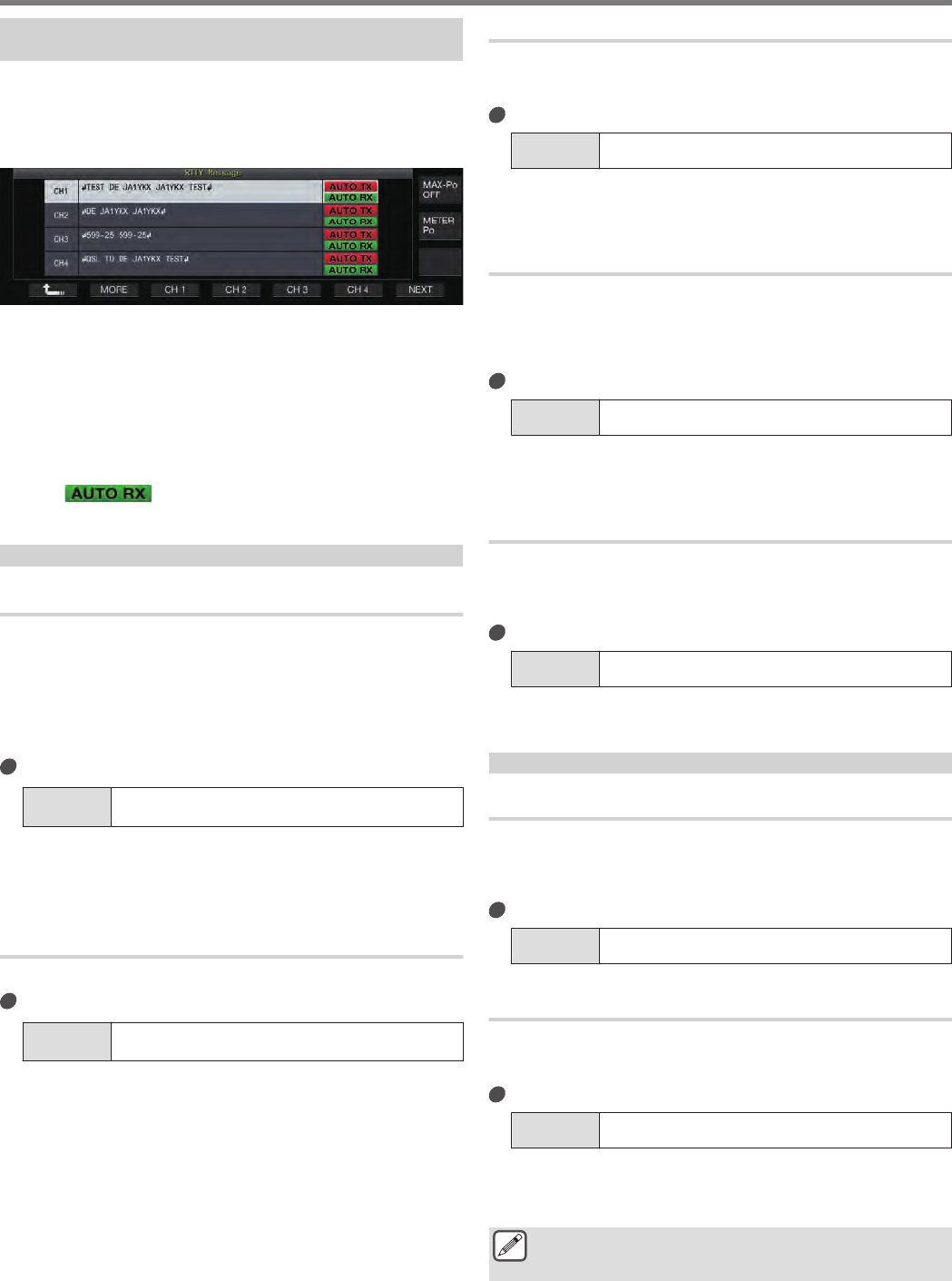
Transmitting Character Strings from the RTTY
Message Memory
A message that is registered in the RTTY message memory can
be transmitted as follows.
1Press F5 [MEMORY] to display the RTTY Message
screen.
.
2Press F3 [CH 1] to F6 [CH 4] or F3 [CH 5] to F6 [CH
8] to select the channel that contains the message
to be transmitted.
The RTTY message of the channel corresponding to the
function key is being transmitted automatically.
•If the channel guide is not displayed, press F2 [MORE].
•Pressing F7 [NEXT] each time switches between F3 [CH
1] to F6 [CH 4] and F3 [CH 5] to F6 [CH 8].
•After transmitting the RTTY message that is indicated by an
<< >> display beside it, this transceiver returns
to the RX mode.
Settings Related to RTTY Encode/Decode
Enabling Decode UOS (Unshift on Space)
If a space character is included in the RTTY signal that is received,
the character following the space can be forcibly interpreted as a
character code (alphabet).
In RTTY, garbled characters may appear due to the signal strength
or noise. To avoid this from happening as much as possible, the
character after a space character is interpreted as a more
frequently used character code (alphabet).
Configure in Menu [2-01] “RX UOS”
Setting
Value Off/ On (default)
On: Encodes space characters.
Off: Does not encode space characters.
•To receive a numeric value or symbol that immediately
follows a space character, turn off the UOS function.
Newline Code Setting
Configure the newline code when receiving an RTTY signal.
Configure in Menu [2-02] “Newline Code”
Setting
Value CR+LF/ All (default)
All: Inserts a line break for every newline code.
CR+LF: Inserts a line break only when a CR+LF code is
received.
Diddle Operation
Diddle allows the user to select the type of code to transmit when
the characters to be sent run out during transmission in the RTTY
(FSK) mode.
Configure in Menu [2-03] “Diddle”
Setting
Value Off/ Blank Code (default)/ Letters Code
Off: Does not send out a character code.
Blank Code: Sends out a space character.
Letters Code: Sends out a character code.
Encode UOS
This is used for sending out a numeric value or symbol that
immediately follows a space during transmission in the RTTY
(FSK) mode. Enabling this function allows the receiving station to
recognize the code that comes after a space as a numeric value
or symbol, thus reducing the occurrence of garbled characters.
Configure in Menu [2-04] “TX UOS”
Setting
Value Off/ On (default)
On: Uses encode UOS.
Off: Does not use encode UOS.
Sending a Newline Code at the Start or End of a
Transmission
A newline code (CR+LF) can be sent out when RTTY encode/
decode starts or ends. A line break is inserted before and after the
RTTY message on the decode screen of the receiving station,
which makes it easier to identify the transmitted RTTY message.
Configure in Menu [2-05] “Automatic Newline Insertion”
Setting
Value Off/ On (default)
On: Sends out a newline code.
Off: Does not send out a newline code.
RTTY Parameters
Configuring the Mark Frequency
Configure the frequency of the mark signal that is used for
communication in the RTTY (FSK) mode. The 1275 Hz frequency is
referred to as a low tone, and the 2125 Hz frequency as a high tone.
The high tone is used under normal circumstances.
Configure in Menu [2-08] “FSK Tone Frequency”
Setting
Value 1275/ 2125 (default) [Hz]
Configuring the RTTY Shift Width
The difference between the mark signal frequency and space
signal frequency is called shift width. Configure the shift width
during communication in the RTTY mode.
Configure in Menu [2-06] “FSK Spacing”
Setting
Value 170 (default)/ 200/ 425/ 850 [Hz]
•RTTY shift width cannot be altered when the RTTY
communication screen is open.
•When the shift width in RTTY exceeds 170 Hz, the audio
peak filter for the selected band cannot be set to ON.
●To operate in the RTTY mode using the built-in
demodulator, encoder and decoder of this transceiver,
configure the setting to “170 [Hz]”.
COMMUNICATING AIDS 5
5-21
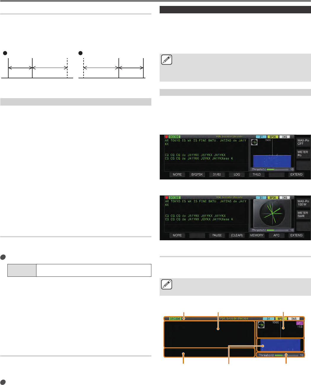
Frequency Reverse in RTTY Mode
Decoding cannot be performed correctly when the RTTY signal
received is in the reverse state (frequencies of the mark signal and
space signal are reversed). When this occurs, press and hold
[FSK/ PSK] to reverse the RTTY signal received so that the
reverse signal can be decoded.
.
Space
Frequency
Mark
Frequency
BFOBFO
Mark
Frequency
Space
Frequency
170 Hz2125 Hz2125 Hz170 Hz
ReverseNormal
Operating RTTY Using an External Device
To operate in the RTTY mode using an external device instead of
the built-in encoder and decoder functions of this transceiver by
configuring this transceiver to the RTTY (FSK) mode, make use of
the ACC 2 connector. Connect the keying output line of the
external device to pin 2 (RTTY) of the ACC 2 connector and the
demodulation input line of the external device to pin 3 (ANO) of the
ACC 2 connector. Also, connect the TX control (PTT) line to pin
13 (SS) of the ACC 2 connector.
•For RTTY transmission using PKS/SS signals of the ACC 2
connector, encoding is performed using the RTK signals input
to the ACC 2 connector. However, if the built-in encoder is
activated during transmission via the PKS/SS signals, encoding
will be performed using the built-in encoder and the RTK signals
from the ACC 2 connector will be ignored. (Transmission of the
built-in message memory is also possible during RTTY
operation using an external device.)
See below for examples of the connection setup (1-4).
•Connection with a PC
•Connection with devices with a built-in TNC
ACC 2 Keying Polarity Setting
When communicating using an external device in the RTTY (FSK)
mode, input keying signals to pin 2 (RTTY) of the ACC 2 connector.
Configure in Menu [2-07] “FSK Keying Polarity”
Setting
Value Off (default)/ On
•Configure the keying polarity of this pin 2 (RTTY) according
to the specifications of the external device. When Menu
[2-07] “FSK Keying Polarity” is configured to “Off” and pin 2
(RTTY) is short-circuited to GND, signals are transmitted at
the mark frequency configured in Menu [2-08] “FSK Tone
Frequency”.
•When Menu [2-07] “FSK Keying Polarity” is configured to
“On”, signals are transmitted as space signals with the mark
frequency shifted by the amount configured in Menu [2-06]
“FSK Spacing”.
Audio Peak Filter
Using the audio peak filter may help to improve the decodability of
RTTY messages when operating in the RTTY (FSK) mode with
this transceiver connected to an external device.
Press F [APF] to set the audio peak filter to ON.
•When audio peak filter is turned on, “ON” is displayed in the
lower row of F [APF].
•When audio peak filter is turned off, “OFF” is displayed in the
lower row of F [APF].
PSK Operation
This transceiver is equipped with a built-in demodulator, encoder
and decoder for operating in the PSK31 and PSK63 modes.
Operation in the PSK31 or PSK63 mode can be performed easily
by connecting a commercially available USB keyboard. PSK can
also be operated using a data communication software program
that makes use of the sound function of a PC.
●When transmitting in the PSK mode, adjust the carrier
until the ALC meter starts to deflect.
●When an external device is used, adjust the audio signal
level from the external device, followed by adjusting the
ALC meter until it starts to deflect.
Displaying the PSK Communication Screen
1Press [FSK/PSK] to select PSK mode.
2Press F3 [DECODE].
The PSK communication screen appears.
Text Display Area + FFT Scope
.
Text Display Area + Vectorscope
.
Switching between the FFT Scope and Vectorscope Display
The display toggles between the “audio FFT scope and waterfall”
and “vectorscope” each time the scope display on the screen is
touched.
●Noise Reduction 1, Noise Reduction 2, Beat Canceler 1,
Beat Canceler 2 and RX DSP equalizer do not function
during decoding of PSK messages.
The layout of the PSK communication screen is as follows.
.
TX Details Display Waterfall Threshold Level
FFT ScopeIndicator TX/RX Details
Indicator
Indicates the status of the function.
TX/RX Details
Displays the character strings that are transmitted or received.
TX Details Display
Character strings to be transmitted.
5 COMMUNICATING AIDS
5-22
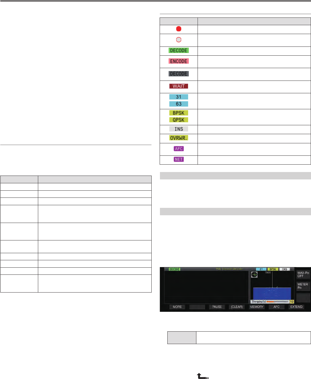
FFT Scope
The audio FFT scope is used for viewing the tuning status.
If there are multiple signals in the band, the target signal is tuned
such that it becomes a 1500 Hz tone.
Zero-in needs to be performed accurately in the PSK mode. Zero-
in the target signal while monitoring the FFT scope and
vectorscope.
Waterfall
Displays the transition in the spectrum of the TX audio signal in
tandem with the FFT scope.
Vectorscope
The vectorscope indicates the way in which the PSK signals
received are tuned. It comes in handy when tuning to the signal of
the target station while monitoring the waveform on the
vectorscope.
Threshold Level
Displays the threshold value of the RX signal input level for
decoding.
Operating the PSK Communication Screen
The following operations are enabled when the PSK
communication screen opens.
•Pressing the [Page Up] or [Page Down] key scrolls the display
of the TX or RX details.
Key Behavior
F1 [MORE] Switches the key guide.
F2 [B/QPSK] Switches between the BPSK and QPSK modes.
F3 [31/63] Switches between the PSK31 and PSK63 modes.
F3 [PAUSE] Pauses update (drawing) of the TX/RX details display
area. Pressing the key again resumes the update
(drawing).
F4 [LOG] Turns ON/OFF the communication log function.
Pressing and holding this key displays the screen for
selecting a log file that is saved.
F4 [(CLEAR)] Pressing and holding the key clears the text displayed
on the TX/RX details screen.
F5 [THLD] Switches to the threshold level configuration mode.
F5 [MEMORY] Switches to the PSK Message screen.
F6 [AFC] Switches the AFC function.
F7 [EXTEND] Enlarges the size of the PSK communication screen.
Pressing it again restores the screen to the standard
size.
Indicator Displays
Display Behavior
.Appears when the communication log function is ON.
.
Appears when the communication log function is ON
and in the standby mode.
.Appears when signal decoding is in progress.
.
Appears when encoding the character strings in the
TX character string buffer.
.
Appears when the decode function is stopped or
disabled.
.
Appears when transmitting the auto standby channel
during transmission of the message memory.
.
.
Displays the baud rate.
.
.
Displays the communication mode.
.Appears when in the insert mode.
.Appears when in the overwrite mode.
.
Appears when AFC is ON.
Displays the difference in frequency at the bottom.
.Appears when NET is ON.
Saving PSK Communication Logs
The CW, RTTY and PSK communication screens can be saved
using the communication log function. Please refer to
“Communication Log” on page 5-27.
Adjusting the PSK Decode Threshold Level
Noise that occurs when there is no signal may sometimes be
erroneously detected as text, which results in the display of
unwanted text. To reduce the occurrence of such issues, adjust
the threshold level. Raise the threshold level when there is
frequent erroneous detection due to noise.
1Press F5 [THLD].
The threshold level setting can now be adjusted.
.
2Press F4 [–]/ F5 [+] or turn the [MULTI/CH] control
to adjust the level.
Setting
Value 1 to 10 (default) to 30 (1 step)
•Adjust the threshold value in the ascending order according
to the receiving status of noise, for example. Start from a
small value between the range of 1 to 30 and configure the
threshold value to a point where reception is good.
3Press F1 [ ] to end the process.
COMMUNICATING AIDS 5
5-23
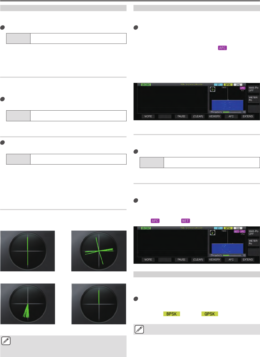
FFT Scope/Vectorscope Display Setting
The tuning scope displayed on the PSK communication screen
can be switched to an “FFT scope” or “vectorscope” display.
Configure in Menu [2-13] “PSK Tuning Scope”
Setting
Value FFT Scope (default)/ Vector Scope
•The display toggles between the “FFT scope” and
“vectorscope” each time the scope display on the screen is
touched.
FFT Scope Waveform Averaging
The waveform displayed on the FFT scope can be averaged.
Averaging of the waveform reduces random noise and makes
observation of the target signal easier.
Configure in Menu [2-10] “FFT Scope Averaging
(PSK Decode)”
Setting
Value 0 (default) to 9 (1 step) (minimum to maximum
averaging)
Selecting a Waterfall Display Type
Configure in Menu [2-17] “Waterfall when Tuning
(RTTY/PSK Audio Scope)”
Setting
Value Straight (default)/ Follow
Straight: Uses a straight line to show transition in the level of
the target signal displayed on the waterfall when the RX
frequency is altered.
Follow: Tracks and displays the latest audio FFT level at the
portion where the waterfall starts flowing when the RX
frequency is altered.
Vectorscope
Turn the Tuning control to perform tuning such that the emission
lines displayed on the vectorscope radiate from the center into the
same direction.
.
Unmodulated Carrier SignalIdle Signal of BPSK or QPSK
In Tune (QPSK)In Tune (BPSK)
●Make use of the fine-tuning function if there is difficulty
in performing tuning.
●While transmission is in progress, the vectorscope does
not function and points to the 12 o’clock direction.
AFC (Automatic Frequency Control)
The AFC (Automatic Frequency Control) function can be used to
tune the PSK signal that is being received.
Press F6 [AFC] to set the AFC function to “On”.
•Pressing F6 [AFC] each time toggles the option in the
following sequence: “OFF” → “AFC ON” →“ AFC&NET ON”
→ “OFF”.
•When the AFC function is ON, the << >> display lights
up. The amount of frequency correction made by the AFC
function is displayed below “AFC”.
•Pressing and holding F6[AFC] while the AFC function is ON
increases or decreases the displayed frequency which
indicates the amount of correction made by the AFC
function.
.
Configuring the AFC Tuning Range
Configure the frequency range for tuning the PSK signals that are
received using the AFC function.
Configure in Menu [2-11] “PSK AFC Tuning Range”
Setting
Value ±8/ ±15 (default) [Hz]
NET
The NET function transmits signals by applying the frequency that
is automatically tuned by AFC.
Press F5 [AFC] to select “AFC & NET”.
•Pressing F5 [AFC] each time toggles the option in the
following sequence: “OFF” → “AFC function ON” →“ AFC
function & NET function ON” → “OFF”.
•<< >> and << >> light up.
.
Switching between BPSK and QPSK
The PSK mode is further divided into 2 sub-modes, namely BPSK
and QPSK. BPSK is the more commonly used mode. QPSK excels
at correcting errors and boasts a higher decoding rate than BPSK.
Press F2 [B/QPSK].
Pressing the key each time toggles the mode between BPSK
and QPSK. The display to the right of the status bar toggles
between << >> and << >> when the mode is
switched.
●This is fixed at BPSK when the PSK63 mode is selected.
5 COMMUNICATING AIDS
5-24
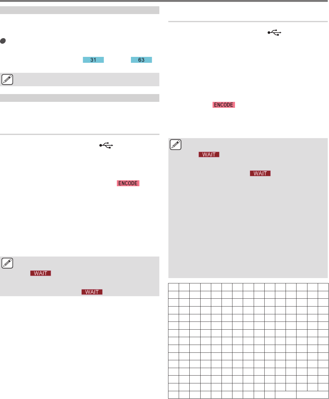
Switching between PSK31 and PSK63
This transceiver supports PSK31 as well as PSK63. The latter has
a transfer rate that is twice that of the BPSK mode. Perform the
following step to toggle between PSK31 and PSK63.
Press F3 [31/63].
It is possible to toggle between BPSK31 and BPSK63 or
between QPSK31 and QPSK63. The display to the right of the
status bar toggles between << >> and << >>
when the mode is switched.
●This is fixed at BPSK when the PSK63 mode is selected.
Transmitting Character Strings from USB Keyboard
A commercially available USB keyboard can be used to input and
transmit character strings.
Transmitting the Input Character String Immediately
1Connect the USB keyboard to (USB-A).
2Press F3 [DECODE] to display the PSK
communication screen.
3Press [F12] on the USB keyboard to switch this
transceiver to the TX mode.
The [BUSY/TX] LED lights up in red, and << >> is
displayed in the status bar.
4Enter a character string using the USB keyboard.
•The input character string is displayed in the TX details
display area and transmitted immediately.
•In the TX details display area, the color of the individual
characters change successively once they are transmitted.
•Characters that have been transmitted appear successively
in the TX/RX details display area.
5Press [F12] on the USB keyboard to switch this
transceiver to the RX mode.
●If there remain characters in the TX details display area
that are not transmitted when [F12] is pressed in step 5,
<< >> is displayed in the status bar. After
transmission of all the character strings is complete, the
transceiver switches to the RX mode and the light of the
[BUSY/TX] LED and << >> display go off.
Temporarily Placing Character Strings in the
Character String Buffer before Transmission
1Connect the USB keyboard to (USB-A).
2Press F3 [DECODE] to display the PSK
communication screen.
3Enter a character string using the USB keyboard.
The input character string is stored temporarily in the TX details
display area.
4Press [F12] on the USB keyboard to send out the
character string that is stored in the character
string buffer.
•Upon entering the TX mode, the [BUSY/TX] LED lights up in
red, and << >> is displayed in the status bar.
•In the TX details display area, the color of the individual
characters change successively once they are transmitted.
5Press [F12] on the USB keyboard to switch this
transceiver to the RX mode.
●If there remain characters in the TX details display area
that are not transmitted when [F12] is pressed in step 5,
<< >> is displayed in the status bar. After
transmission of all the character strings is complete, the
transceiver switches to the RX mode and the light of the
[BUSY/TX] LED and << >> display go off.
●Pressing [ESC] while transmission of the character
strings is in progress switches this transceiver to the RX
mode. Transmission of the character strings stops, and
character strings in the TX details display area that are
not yet transmitted are cleared.
●Time stamp and frequency information can be added to
the TX or RX data that is displayed in the TX/RX details
display area.
●Sending a character string using the USB keyboard while
the TX/RX display is paused by pressing F3 [PAUSE]
cancels the paused state.
●The character strings that can be placed temporarily in
the TX details display area can contain a maximum of
4300 characters.
●Characters and symbols that can be input using a USB
keyboard are as follows.
A B C D E F G H I J K L M N O
P Q R S T U V W E X Y Z
0123456789
a b c d e f g h i j k l m n o
p q r s t u v w x y z
À Á Â Ã Ä Å Æ Ç È É Ê Ë Ì Í Î
Ï Ð Ñ Ò Ó Ô Õ Ö Ø Ù Ú Û Ü Ý Þ
à á â ã ä å æ ç è é ê ë ì í î
ï ð ñ ò ó ô õ ö ø ù ú û ü ý þ
ÿ ß
! " # $ % & ’ ( ) * + , - . /
: ; < = > ? @ [ \ ] ^ _ ` { |
} ~ ¡ ¢ £ ¤ ¥ ¦ § ¨ © ª « ¬ ®
¯ ° ± ² ³ ´ µ ¶ • ¸ ¹ º » ¼ ½
¾ ¿ No ÷ Space Line Break
•The chart above shows the characters and symbols that can be
input when “English” is selected in Menu [9-01]. To input
Japanese characters, please download and refer to the
Japanese instruction manual from our website.
COMMUNICATING AIDS 5
5-25
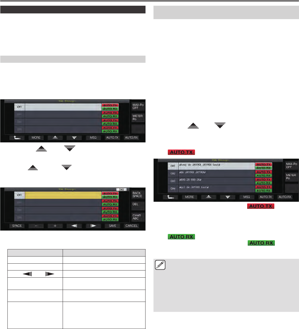
PSK Message Memory
Fixed phrases that are often used in the PSK mode can be
registered in advance as a message in the message memory.
Adding the auto TX and auto RX functions to the fixed phrases
enables messages to be sent out via simple operation.
•Up to 8 types of messages can be registered.
Registering Messages
1Press F3 [DECODE] to display the PSK
communication screen.
2Press F5 [MEMORY] to display the PSK Message
screen.
.
3Press F3 [ ]/ F4 [ ] or turn the [MULTI/CH]
control to select the channel for registering the
message.
•If F3 [ ] and F4 [ ] are not displayed in the key
guide, press F1 [MORE] to toggle the key guide display.
4Press F5 [MSG].
.
5Use the function keys, [MULTI/CH] control or USB
keyboard to enter a character string.
Key Behavior
F1 [SPACE] Inserts a space.
F2 [–]/ F3 [+] Selects a character.
F4 [ ]/ F5 [ ] Moves the cursor.
F [BACK SPACE] Deletes the character to the left of the
cursor.
F [DEL] Deletes the character to the right of the
cursor.
F [CHAR]
Switches the type of character to edit.
Pressing the key each time switches the
selection in the following sequence:
ABC (upper case) → abc (lower case)
→ !”# (symbols) → ABC (upper case)
•Pressing F7 [CANCEL] discards the content that is currently
being edited and exits the character string input mode.
6Press F6 [SAVE] to save the edited message.
Configuring Auto TX/RX for the PSK Message
Memory
The transmission and reception behavior can be configured when
a PSK message memory channel is selected.
•Auto TX places this transceiver in the TX mode before
transmitting a message when a message memory channel is
selected, and maintain the TX mode after all messages have
been sent out.
•For auto RX, pressing [F12] after selecting a message memory
channel for transmission places this transceiver in the TX mode.
When the message is sent out, this transceiver is automatically
restored to the RX mode.
•Combining auto TX and auto RX enables both transmission and
reception to be performed automatically.
1Press F3 [DECODE] to display the PSK
communication screen.
2Press F5 [MEMORY] to display the PSK Message
screen.
3Press F3[ ]/ F4[ ] or turn the [MULTI/CH]
control to select the channel containing the
message for auto TX/RX.
4Press F6 [AUTO.TX] to set auto TX to ON.
<< >> is displayed to the right of the PSK message.
.
•When auto TX is set to OFF, the << >> display
goes off, and the PSK message of the channel is temporarily
placed in the character string buffer but not transmitted
automatically.
5Press F7 [AUTO.RX] to set auto RX to ON.
<< >> is displayed to the right of the PSK message.
•When auto RX is set to OFF, the << >> display
goes off, and this transceiver is not restored to the RX mode
after the PSK message for the channel has been sent out.
●To sent an PSK message for which “AUTO TX” is set to
ON, select the channel in which the PSK message is
stored. Check to ensure that the character string (PSK
message) is forwarded to the TX details display area,
followed by pressing [F12] on the USB keyboard.
●To switch this transceiver to the RX mode after
transmitting an PSK message for which “AUTO RX” is
set to OFF, press [F12] on the USB keyboard after the
PSK message has been sent out.
5 COMMUNICATING AIDS
5-26
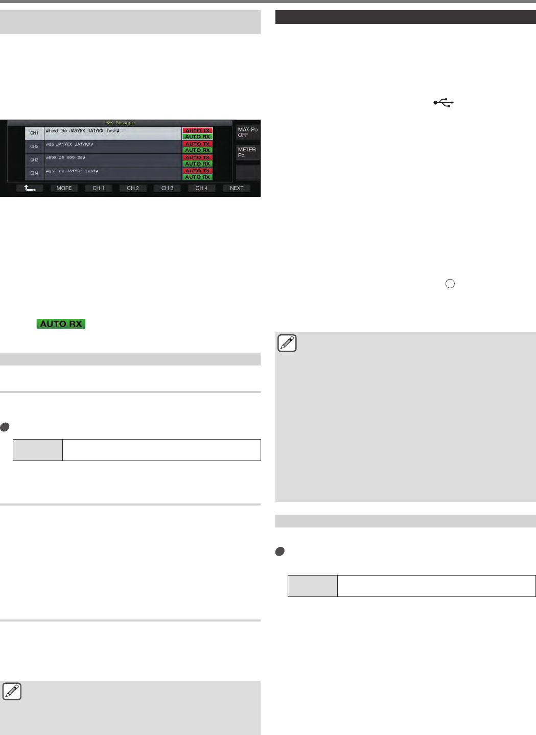
Transmitting Character Strings from the PSK
Message Memory
A message that is registered in the PSK message memory can be
transmitted as follows.
1Press F3 [DECODE] to display the PSK
communication screen.
2Press F5 [MEMORY] to display the PSK Message
screen.
.
3Press F3 [CH 1] to F6 [CH 4] or F3 [CH 5] to F6 [CH
8] to select the channel that contains the message
to be transmitted.
The PSK message of the channel corresponding to the function
key is being transmitted automatically.
•However, the PSK message will not be transmitted
automatically if auto TX is set to OFF.
•If the channel guide is not displayed, press F2 [MORE].
•Pressing F7 [NEXT] each time switches between F3 [CH
1] to F6 [CH 4] and F3 [CH 5] to F6 [CH 8].
•After transmitting the PSK message that is indicated by an
<< >> display beside it, this transceiver returns
to the RX mode.
Settings Related to PSK
Configuring the PSK Tone Frequency
Configure the tone frequency when signals are received in the PSK
mode.
Configure in Menu [2-12] “PSK Tone Frequency”
Setting
Value 1.0/ 1.5 (default)/ 2.0 [kHz]
Reversing the Direction of Phase Change in the QPSK
Mode
•When the QPSK signal received cannot be decoded correctly,
try decoding with the BFO frequency switched from the LSB
side to the USB side.
•Decoding cannot be performed correctly when the BFO
frequency of the PSK signal received is in the reverse state
(frequencies of the lower and upper sidebands are reversed).
•Pressing and holding the [FSK/PSK] mode key enables
reverse signals to be decoded.
PSK Operation Using a PC
For details on operation in the PSK mode using a data
communication software program that makes use of the sound
function of a PC instead of the built-in encoder and decoder
functions of this transceiver while this transceiver is configured to
the SSB-DATA mode, please refer to “PC Connection”.
●As audio from an external input cannot be transmitted in
the PSK mode, make use of the SSB or SSB-DATA
mode.
●Alternatively, audio from an external device can also be
transmitted using the DATA VOX function.
Communication Log
The CW, RTTY and PSK communication screens can be saved
using the communication log function.
•Before doing so, configure the destination for saving the data in
“File Storage Location” of the “USB/File Management Menu” to
“Internal Memory” or “USB Flash Drive”. (See 11-12)
•To save the data to a USB flash drive, insert a USB flash drive
formatted using this transceiver into (USB-A).
1Set to the CW, RTTY (FSK) or PSK mode.
2Press F3 [DECODE] to display the corresponding
communication screen.
3Press F4 [LOG] to set the communication log
function to “On”.
Pressing F4 [LOG] each time toggles the communication log
function between ON and OFF.
•“Log: On” appears on the communication screen for about
1 second when the communication log function is ON, and
“Log: Off” is displayed for about 1 second when the function
is OFF.
•When the communication log function is functioning in the
ON mode, the communication log ON indicator is displayed
on the title bar.
•When the communication log function is ON and the
transceiver is in the standby mode, “” is displayed on the
title bar. (When there is insufficient space in the USB flash
drive or when a USB flash drive is not inserted when the
destination for saving the logs is configured to a USB flash
drive.)
●The file name is made up of the date and time in
numerical format together with an underscore. The
extension of the file is based on the selection made in
Menu [2-14] “CW/RTTY/PSK Log File Format”. The date
and time is expressed in the following sequence:
yyyymmdd_hhmmss.
•(Example)
•If the date is 10:20:30 a.m., February 15, 2018:
•20180215_102030.txt
●The file is stored in the following folder.
•CW: KENWOOD\TS-890\DECODE\CW
•RTTY: KENWOOD\TS-890\DECODE\RTTY
•PSK: KENWOOD\TS-890\DECODE\PSK
●When removing the USB flash drive, make sure to
execute “Safe Removal of USB Flash Drive”. (See
11-6)
Selecting a Log File Format
Select a format for the log file to be saved.
Configure in Menu [2-14] “CW/RTTY/PSK Log File
Format”
Setting
Value html/ txt (default)
html: Saves the log file in the html format.
txt: Saves the log file in the text format.
COMMUNICATING AIDS 5
5-27
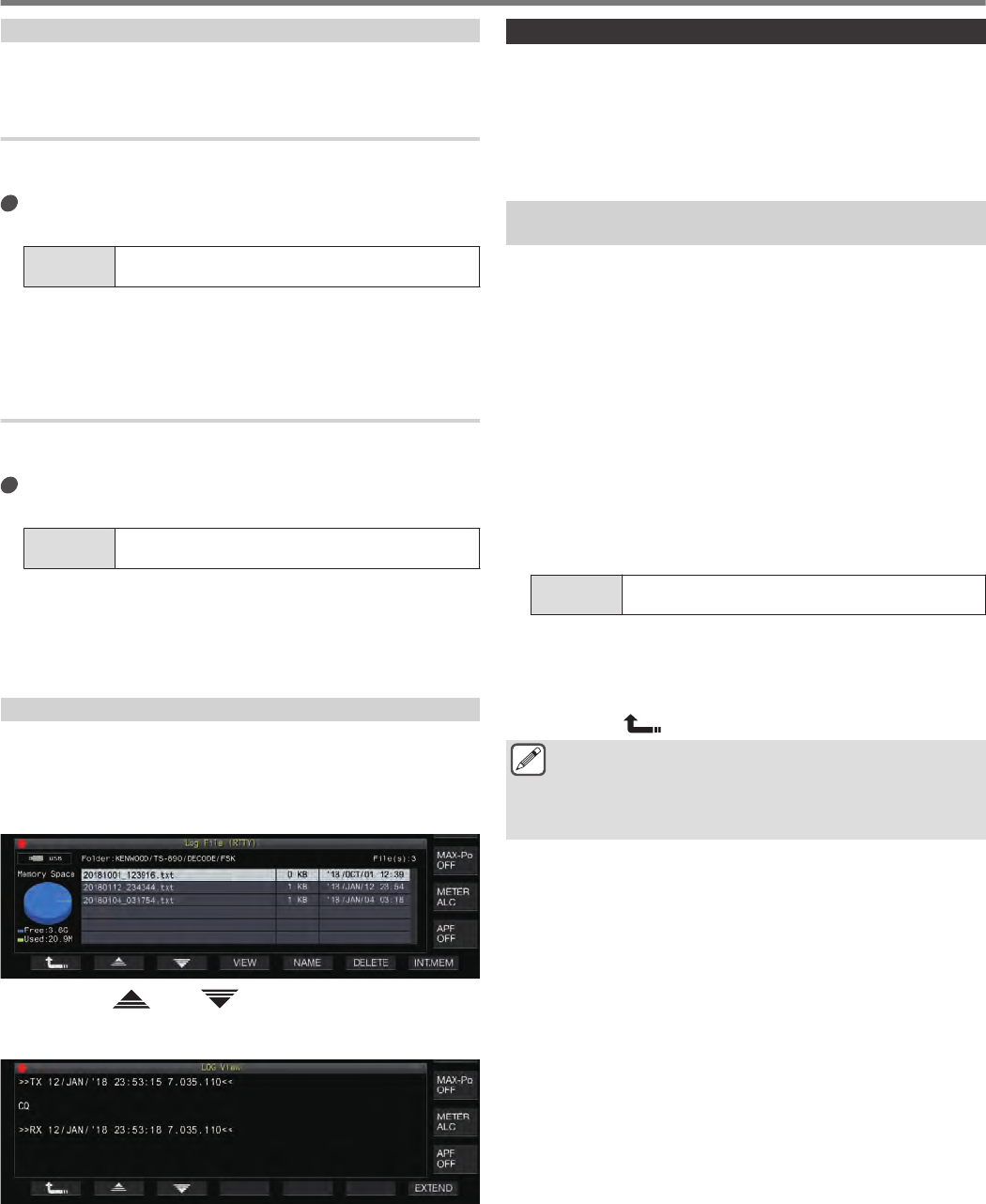
Displaying a Time Stamp
A time stamp can be automatically inserted into the “TX/RX details
display area” when switching between the RX and TX mode.
Selecting a Time Stamp Type
It is possible to select whether to display only the time stamp or to
display both the time stamp and frequency.
Configure in Menu [2-15] “CW/RTTY/PSK Time
Stamp”
Setting
Value Off/ Time Stamp/ Time Stamp+Frequency (default)
Off: Does not display a time stamp.
Time Stamp: Displays only the time stamp.
Time Stamp+Frequency: Displays both the time stamp and
frequency.
Selecting a Clock Type
Configure the clock for displaying the time stamp to a “Local Clock”
or “Secondary Clock”.
Configure in Menu [2-16] “Clock (CW/RTTY/PSK
Time Stamp)”
Setting
Value Local Clock (default)/ Secondary Clock
•When encoding or decoding starts, a line break and time
stamp will be inserted before displaying the encoded or
decoded character string.
•A time stamp is inserted when there is a change in the
encoding or decoding status.
Editing the Communication Log File
1In the CW communication screen, press and hold
F2 [LOG]. In the RTTY and PSK communication
screens, press and hold F4 [LOG].
The screen for selecting log file appears.
.
2Press F2[ ]/ F3[ ] to select a file.
•Pressing F4 [VIEW] displays the log information of the
selected file.
.
•To read data from the internal memory, press F7 [INT.MEM].
•To read data from the USB flash drive, press F7
[USB.MEM]. (If a USB flash drive is not connected, a message
will appear prompting you to get ready the USB flash drive.)
•Pressing F5 [NAME] allows the file name to be changed.
•Pressing F6 [DELETE] displays a message to confirm
deletion of the file. Pressing F4 [OK] deletes the file.
Operation in FM Mode
Operating in the FM mode enables high-quality voice
communication as well as communication that is noise-resistant.
Communication in the FM mode is also supported on the 29 MHz,
50 MHz and 70 MHz (E type) bands. To communicate with a
distant station for which communication cannot be established
directly, do so via a repeater.
Adjusting Microphone Gain during Operation in FM
Mode
1Adjust the frequency.
2Press [FM/AM/FM-N] to select FM mode.
3Press F [ADV.] on the menu screen.
4Select Advanced Menu [10] “Microphone Gain (FM
Mode)”.
5Press [SEND], or press and hold [PTT] on the
microphone.
This transceiver is placed in the TX mode and a level meter is
displayed.
6Speak into the microphone in the normal tone and
loudness.
7Press F4 [–]/ F5 [+] or turn the [MULTI/CH] control
to adjust the microphone gain.
Setting
Value 0 to 50 (default) to 100 (1 step)
•Adjust the microphone gain level such that the peak value
of the level meter falls within the zone.
8Press [SEND] or release [PTT] on the microphone.
Doing so places this transceiver in the RX mode.
9Press F1 [ ].
●When using a microphone with a low sensitivity such as
the MC-90, adjust the microphone gain to a higher level.
●When a microphone with a low sensitivity is used, the
modulation factor may stabilize by setting the speech
processor to ON.
5 COMMUNICATING AIDS
5-28
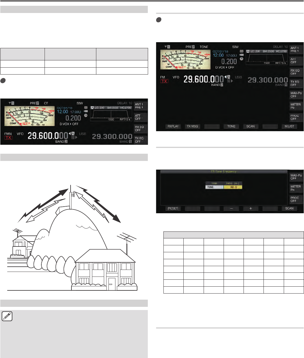
Operation in Narrow FM Mode
It is possible to switch to a narrow bandwidth during operation in
the FM mode. The occupied bandwidth and maximum modulation
factor are shown in the table below. Selecting FM Narrow
according to the modulation factor of the target station helps to
avoid distortion and deterioration in the clarity of the RX audio.
Mode Occupied Bandwidth Maximum Modulation
Factor
FM (Wide) 16 kHz or lower ±5 kHz or lower
FM Narrow 10 kHz or lower ±2.5 kHz or lower
Press and hold [FM/AM].
Pressing and holding [FM/AM] each time switches between
“FM” and “FMN (Narrow)”.
.
Operating the FM Repeater
Switching this transceiver to split operation and turning on the tone
signal while in the FM mode enables this transceiver to be used in
the repeater operation mode.
.
88.5 Hz
29.520 MHz
29.620 MHz
29.620 MHz
88.5 Hz
29.520 MHz
Configuring the Tone Signal
●Registering the tone settings to a memory channel and
calling up the frequency or operation information from
the memory channel eliminates the need to configure the
tone frequency each time. For more details on the
memory channel settings, please refer to “Memory
Channel”.
●The tone frequency may vary depending on the country
or region this transceiver is being used.
Selecting a Tone
Press F4 [TONE] to select “TONE”.
Pressing F4 [TONE] each time toggles the tone signal selection
in the following sequence: “TONE” → “CTCSS (CT)” →
“CROSS” → Blank (deselected).
.
Configuring the Tone Frequency
1Press and hold F4 [TONE] to display the FM Tone
Frequency screen.
.
2Press F4 [–]/ F5 [+] or turn the [MULTI/CH] control
to select the tone frequency.
Tone Frequency (Hz)
67.0 88.5 114.8 151.4 177.3 203.5 250.3
69.3 91.5 118.8 156.7 179.9 206.5 254.1
71.9 94.8 123.0 159.8 183.5 210.7 1750
74.4 97.4 127.3 162.2 186.2 218.1
77.0 100.0 131.8 165.5 189.9 225.7
79.7 103.5 136.5 167.9 192.8 229.1
82.5 107.2 141.3 171.3 196.6 233.6
85.4 110.9 146.2 173.8 199.5 241.8
•The default setting is “88.5 Hz”.
•To restore the default setting, press and hold F1
[(RESET)].
Tone Frequency Scan
Tone frequency that is contained in signals received in the FM
mode can be searched and displayed with the following steps. This
is useful when there is a need to know the tone frequency of the
repeater station.
1Press and hold F4 [TONE] to display the FM Tone
Frequency screen.
2Press F7 [SCAN] to start tone frequency scan.
•Scanning stops when a tone frequency is detected, and the
frequency is displayed in the “FREQ. [Hz]” field.
•Pressing F7 [SCAN] while tone frequency scan is in progress
stops the scan operation. Pressing F7 [SCAN] again resume
scanning.
•The scan operation stops when the RX signal is interrupted
during tone frequency scan. Scanning resumes when a RX
signal is detected by this transceiver.
COMMUNICATING AIDS 5
5-29
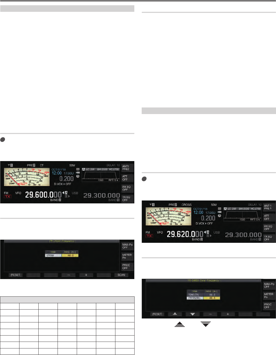
CTCSS Operation
CTCSS is the abbreviation for Continuous Tone Coded Squelch
System. It is used to add a CTCSS tone frequency that is
determined in advance with the target station to the audio signal
to be transmitted. When the CTCSS tone frequency contained in
the RX signal received from the target station coincides with the
CTCSS tone frequency of one’s own station, the squelch opens
and the RX audio can be heard.
•A different value can be selected for CTCSS tone frequency and
tone frequency, but CTCSS and tone cannot be used
concurrently.
•CTCSS tone frequency: Squelch opens upon receiving a
CTCSS tone for which the FM wave is superimposed with the
same CTCSS tone frequency as that configured on this
transceiver.
•During CTCSS frequency scan, it is possible to detect the
CTCSS tone frequency that is contained in the RX signal.
•When a signal is received while CTCSS tone frequency scan is
in progress, the RX audio can be heard even when the CTCSS
tone frequency does not coincide with that configured on this
transceiver.
Selecting CTCSS
Press F4 [TONE] to select “CTCSS (CT)”.
Pressing F4 [TONE] each time toggles the tone signal selection
in the following sequence: “TONE” → “CTCSS (CT)” →
“CROSS” → Blank (deselected).
.
Configuring the CTCSS Frequency
1Press and hold F4 [TONE] to display the FM Tone
Frequency screen.
.
2Press F4 [–]/ F5 [+] or turn the [MULTI/CH] control
to select the CTCSS frequency.
CTCSS Frequency (Hz)
67.0 88.5 114.8 151.4 177.3 203.5 250.3
69.3 91.5 118.8 156.7 179.9 206.5 254.1
71.9 94.8 123.0 159.8 183.5 210.7
74.4 97.4 127.3 162.2 186.2 218.1
77.0 100.0 131.8 165.5 189.9 225.7
79.7 103.5 136.5 167.9 192.8 229.1
82.5 107.2 141.3 171.3 196.6 233.6
85.4 110.9 146.2 173.8 199.5 241.8
•The default setting is “88.5 Hz”.
•To restore the default setting, press and hold F1 [(RESET)].
CTCSS Frequency Scan
CTCSS frequency that is contained in signals received in the FM
mode can be searched and displayed with the following steps. This
is useful when there is a need to know the CTCSS frequency of
the mobile station.
1Press and hold F4 [TONE] to display the CTCSS
Frequency screen.
2Press F7 [SCAN] to start tone frequency scan.
•Scanning stops when a CTCSS frequency is detected, and the
frequency is displayed in the “FREQ. [Hz]” field.
•Pressing F7 [SCAN] while CTCSS frequency scan is in
progress stops the scan operation. Pressing F7 [SCAN] again
resume scanning.
•The scan operation stops when the RX signal is interrupted
during CTCSS frequency scan. Scanning resumes when a RX
signal is detected by this transceiver.
Cross Tone
Make use of cross tone for communication with a repeater that
requires a different tone for transmission to the repeater (uplink)
and reception from the repeater (downlink).
•Cross Tone frequency uses the tone frequency during
transmission and the CTCSS frequency during reception.
•The tone squelch operates using the CTCSS frequency during
reception, while the preconfigured tone frequency is used to
transmit a tone during transmission.
Selecting Cross Tone
Press F4 [TONE] to select “CROSS”.
Pressing F4 [TONE] each time toggles the tone signal selection
in the following sequence: “TONE” → “CTCSS (CT)” →
“CROSS” → Blank (deselected).
.
Configuring the TX/RX Tones
1Press and hold F4 [TONE] to display the FM Cross
Tone Frequency screen.
.
2Press F2 [ ]/ F3 [ ] to select “TONE (TX)” or
“CTCSS (RX)”.
3Press F4 [–] / F5 [+] or turn the [MULTI/CH] control
to select the tone frequency or CTCSS frequency.
•To restore the default setting of the selected row, press and
hold F1 [(RESET)].
5 COMMUNICATING AIDS
5-30
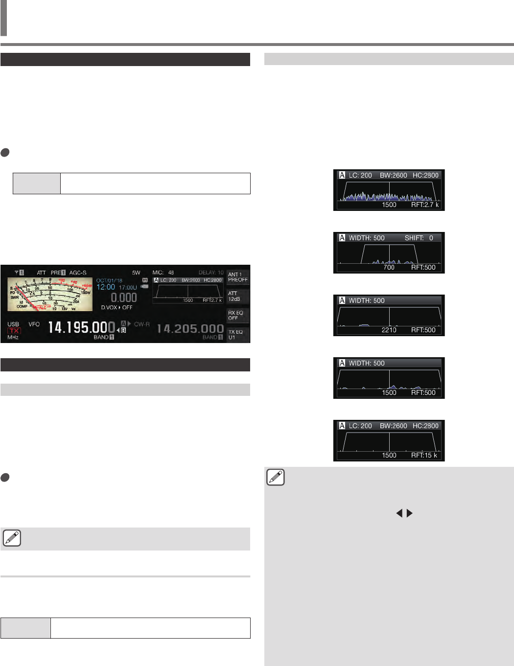
Attenuator
The attenuator is a function for attenuating the RX signals. If there
is interference due to strong signals near the target signal, turning
on the attenuator helps to reduce interference caused by nearby
frequencies.
It is also effective in situations where the RX audio is distorted
when the RX signal is too strong. This transceiver comes with three
different types of attenuators.
Press F [ATT].
Pressing F [ATT] each time switches the attenuation level.
Setting
Value Off (default)/ 6 dB/ 12 dB/ 18 dB
•Pressing and holding F [ATT] each time switches the options
in the reverse sequence.
•The attenuation level is stored for each antenna selection
band.
•The status of the attenuator (attenuation level) is displayed
in the key guide.
.
Switching the IF Filter Band Characteristics
Switching the RX Filter (A, B, C)
The setting for the band characteristics of the IF filter on this
transceiver can be switched at one touch according to the
operating status to one of the three types (A, B or C).
•The band characteristics are configured by combining the
roofing filter or IF and AF filter, high-cut/low-cut and WIDTH/
SHIFT. A different RX filter setting (A, B or C) can be stored for
each of the SSB, CW, FSK, PSK, FM and AM modes.
Press [IF FIL].
Pressing [IF FIL] each time switches the RX filter in the order
of “A”, “B” and “C”.
•The selected filter is displayed at the top left of the filter
scope.
The RX filter does not switch to Type C if Menu [6-10] “RX
Filter Numbers” below is configured to “2”.
Configuring the Selectable Types of RX Filters
The selectable types of RX filters can be configured to three (A, B
and C) or two (A and B).
Configure in Menu [6-10] “RX Filter Numbers”
Setting
Value 2/ 3 (default)
Filter Scope
The following information is displayed on the filter scope screen.
•Selected RX filter (A, B or C)
•Image of the IF filter passband characteristics
•Demodulated audio signal
•Parameters including the IF filter passband width
•Pitch frequency in the CW mode
•Notch point of the notch filter
•Passband width of the roofing filter
.
SSB
AM/FM
PSK
FSK
CW
●Audio signals are not shown when the audio scope
screen is displayed.
●Audio signals are not shown when the RTTY/PSK
communication screen is displayed.
●An out-of-range marker ( ) is displayed if an image
of the passband characteristics is not displayed in the
drawing area.
●Audio FFT is generally displayed within the trapezoidal
waveform, but may extend beyond it in some rare cases
such as when there is input of a large signal.
●Sideband on the positive side with respect to the carrier
wave is drawn on the audio scope. In principle, sideband
also exists on the negative side of the carrier wave in the
AM mode. As such, changing the notch point may cause
it to shift to the sideband on the negative side. When a
notch filter is used concurrently, the marker of the notch
point may shift to the sideband on the negative side. In
this case, the marker is displayed in the folded state.
When the marker is in the folded state, it is displayed in
a color that is different from the usual color.
REJECTING INTERFERENCE 6
6 REJECTING INTERFERENCE
6-1
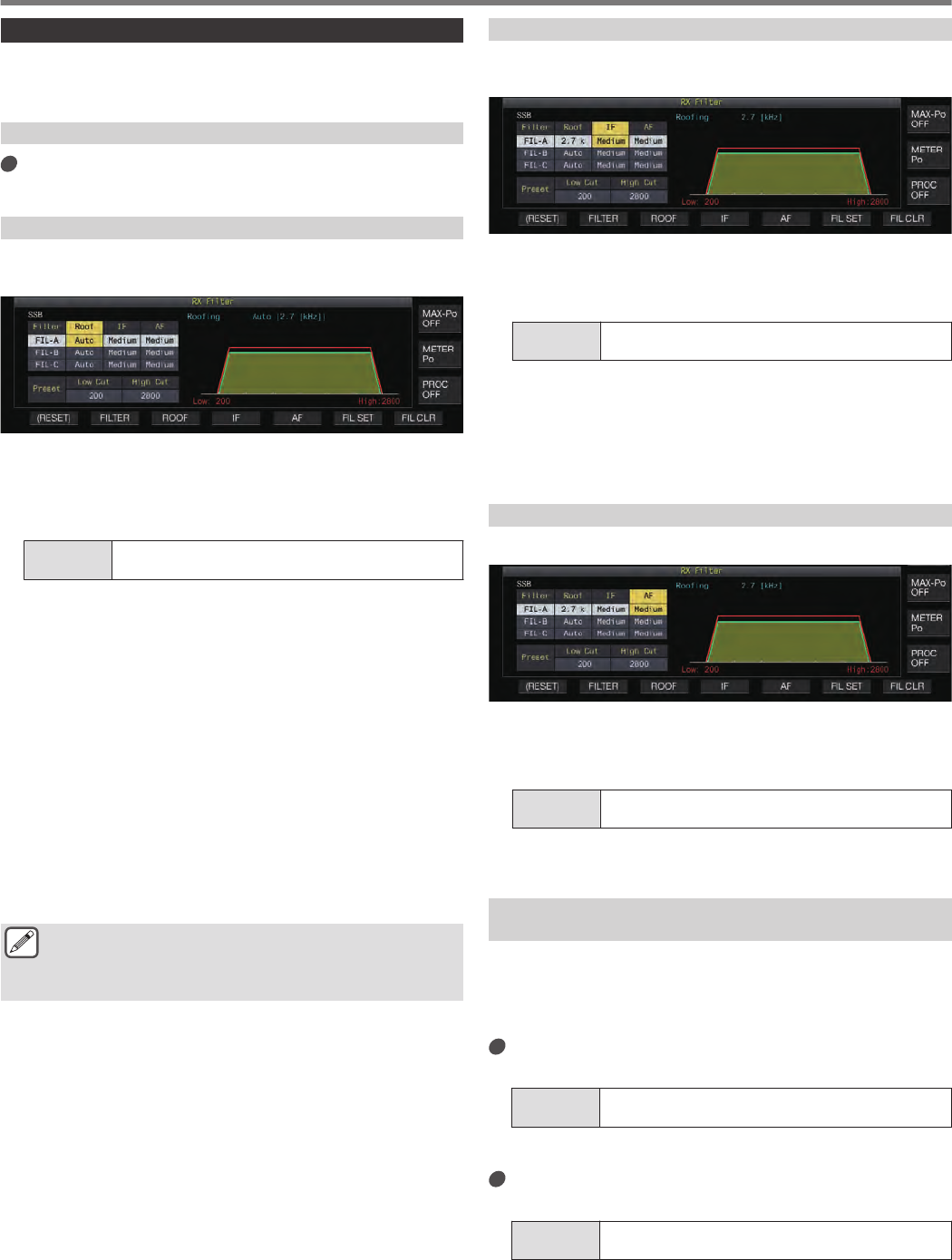
RX Filter Screen
The steps to configure the settings for the different types of RX
filters are as follows.
Displaying the RX Filter Screen
Press and hold [IF FIL] to display the RX Filter
screen.
Selecting a Roofing Filter
A roofing filter helps to reduce strong interference signals that are
next to the target signal.
.
1Press [IF FIL] or F2 [FILTER] to select an RX filter
(FIL-A/B/C).
2Press F3 [ROOF].
Pressing F3 [ROOF] each time switches the passband width.
Setting
Value Auto (default)/ 270/ 500/ 2.7 k/ 6 k/ 15 k [Hz]
Auto: A roofing filter with a bandwidth wider than the passband
width of the DSP filter is automatically selected using high cut/
low cut or Width/Shift. (If there are 2 or more bandwidths that
satisfy the conditions, the narrower one is selected.)
•In the AM mode, a 6 kHz roofing filter is automatically
selected if the high cutoff frequency is 3 kHz or lower, and a
15 kHz roofing filter is selected if the high cutoff frequency
is higher than 3 kHz.
•In the FM mode, the option is fixed at 15 kHz and cannot be
changed.
•270 Hz is available for selection when the optional
YG-82CN-1 is attached.
•Pressing and holding F3 [ROOF] each time switches the
options in the reverse sequence.
•The passband width can also be altered by turning the
[MULTI/CH] control.
•“RFT:xxxx” is displayed at the bottom right of the filter scope.
[xxxx:270/ 500/ 2.7k/ 6k/ 15k]
●The IF passband width for the AM mode is twice the
value of the high cutoff frequency.
Example: If the frequency is 3,000 Hz, the IF passband
width will be 6 kHz.
Switching the IF Filter Shape
3 types of IF filter shapes are available for selection according to
the condition of interference and operation.
.
1Press [IF FIL] or F2 [FILTER] to select an RX filter.
2Press F4 [IF].
Pressing F4 [IF] each time switches the shape of the filter.
Setting
Value Medium (default)/ Soft/ Sharp
•Pressing and holding F4 [IF] each time switches the options
in the reverse sequence.
•The filter shape can also be altered by turning the
[MULTI/CH] control.
•The IF filter option is displayed as “-” and cannot be altered
in the FM mode.
Switching the AF Filter Type
3 types of audio frequency passbands are available for selection.
.
1Press [IF FIL] or F2 [FILTER] to select an RX filter.
2Press F5 [AF].
Pressing F5 [AF] each time switches the shape of the IF filter.
Setting
Value Medium (default)/ Wide/ Narrow
•Pressing and holding F5 [AF] each time switches the
options in the reverse sequence.
Configuring the Behavior of the HI/SHIFT and LO/
WIDTH Controls (SSB/SSB-DATA Only)
The high cut/low cut selection in the SSB mode and Shift/Width
selection in the SSB-DATA mode are preconfigured in the default
setting, but they can be changed in the menu.
SSB Mode
Configure in Menu [6-11] “Filter Control in SSB
Mode (High/Low and Shift/Width)”
Setting
Value High & Low Cut (default)/ Shift & Width
SSB-DATA Mode
Configure in Menu [6-12] “Filter Control in SSB-
DATA Mode (High/Low and Shift/Width)”
Setting
Value High & Low Cut/ Shift & Width (default)
6 REJECTING INTERFERENCE
6-2
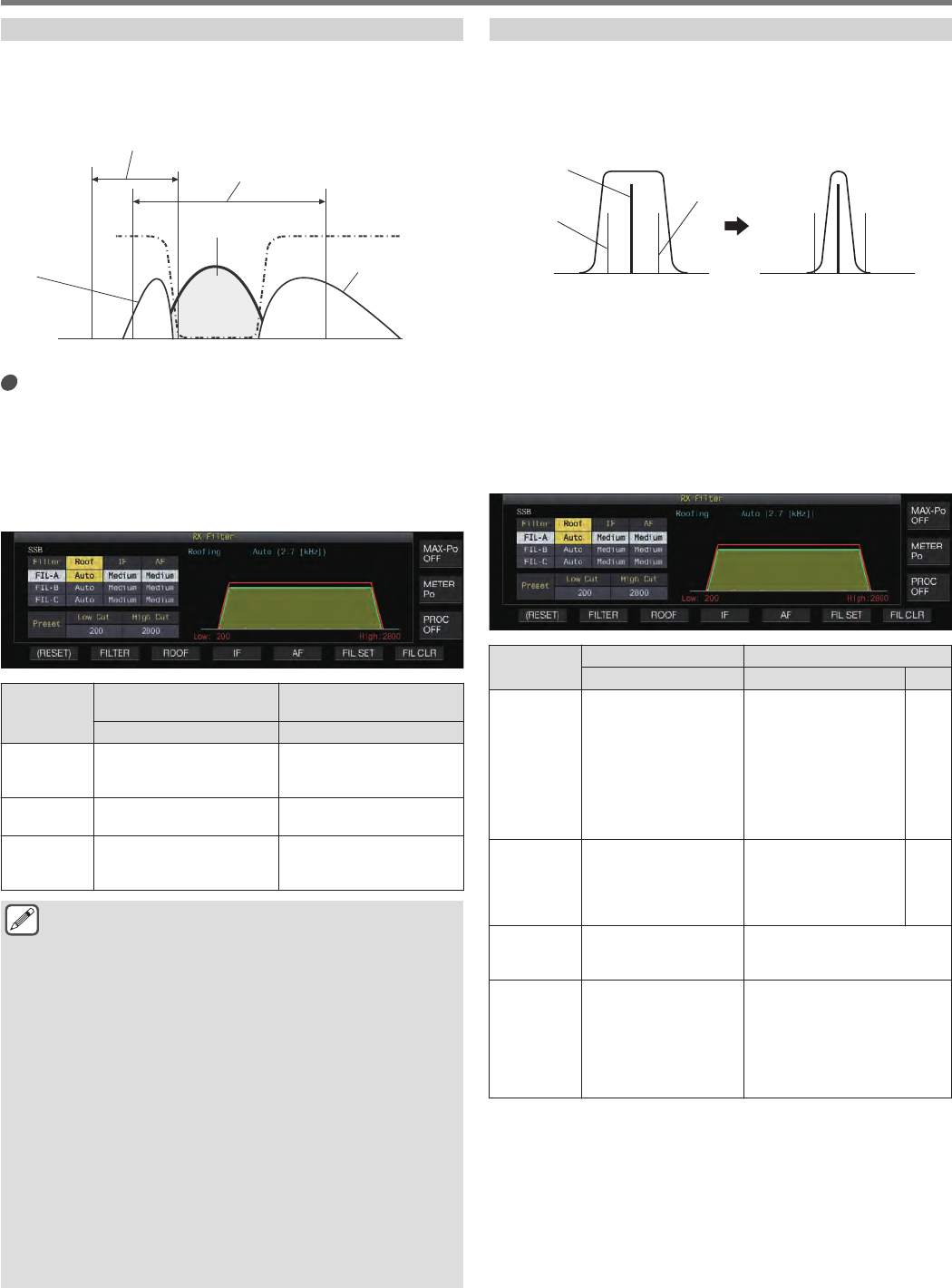
Changing the Cutoff Frequency
In the SSB, AM and FM modes, the passband width of the filter
can be altered by changing the cutoff frequency (low or high).
The passband width can be changed so that the interfering signal
falls outside the bandwidth of the filter.
.
5 KHz2 KHz600 Hz0 Hz
Interfering Signal
Target Signal
Interfering
Signal
High Cut Frequency Range
Low Cut Frequency Range
Turn the [HI/SHIFT] or [LO/WIDTH] control.
•Turning the [HI/SHIFT] control to the right increases the
cutoff frequency (high) while turning the control to the left
decreases the frequency.
•Turning the [LO/WIDTH] control to the right increases the
cutoff frequency (low) while turning the control to the left
decreases the frequency.
•The amount of change and the filter shape are displayed.
.
Mode
Low Cutoff Frequency
(Hz) High Cutoff Frequency
(Hz)
Setting Value Setting Value
SSB/ SSB-
DATA 0/ 50/ 100 to 200 (default) to
2000 (100-step)
600 to 2800 (default) to
3000 (100-step)/ 3400/
4000/ 5000
AM/ AM-
DATA 0/ 100 (default) to / 200/ 300 2000 to 3000 (100-step)/
3500/ 4000/ 5000 (default)
FM/ FM-
DATA 0/ 50/ 100 to 200 (default) to
1000 (100-step)
1000 to 2800 (default) to
3000 (100-step)/ 3400/
4000/ 5000
●When configured to “Auto”, a roofing filter with a
bandwidth wider than the passband width of the DSP
filter is selected using high cut/low cut or Width/Shift.
●When “Auto” is configured in the AM mode, a 6 kHz
roofing filter is automatically selected if the high cutoff
frequency is 3 kHz or lower, and a 15 kHz roofing filter is
selected if the high cutoff frequency is higher than 3 kHz.
●When the RX Filter screen is displayed, turning the [HI/
SHIFT] or [LO/WIDTH] control changes the value of the
cutoff frequency (low and high). The cutoff frequency
value (low and high) is displayed on the RX Filter screen.
●In the FM mode, the option is fixed at 15 kHz and cannot
be changed.
●When the low cutoff frequency is increased until it
reaches the high cutoff frequency, the high cutoff
frequency will also change at the same time while
keeping the passband width at 0 Hz.
●When the high cutoff frequency is decreased until it
reaches the low cutoff frequency, the low cutoff
frequency will also change at the same time while
keeping the passband width at 0 Hz.
Changing the Passband Width and Shift Amount
When in the CW or SSB-DATA mode, the passband width and shift
amount of the DSP filter can be altered. When in the RTTY (FSK)
or PSK mode, the passband width can be changed. The passband
width can be changed so that the interfering signal falls outside the
bandwidth of the filter.
.
Interfering Signal
Interfering
Signal
Target Signal
1Turn the [LO/WIDTH] control to change the
passband width.
Turning the control to the right widens the passband width,
while turning to the left narrows it.
2Turn the [HIGH/SHIFT] control to shift the frequency
band.
Turning the control to the right shifts the frequency to the high
bandwidth, while turning to the left shifts it to the low bandwidth.
•The shift frequency band cannot be adjusted in the FSK and
PSK modes.
.
Mode Passband Width (Hz) Shift Frequency (Hz)
Setting Value Setting Value Step
SSB/ SSB-
DATA
50/ 80/ 100/ 150/ 200/
250/ 300/ 350/ 400/ 450/
500/ 600/ 700/ 800/ 900/
1000/ 1100/ 1200/ 1300/
1400/ 1500/ 1600/ 1700/
1800/ 1900/ 2000/ 2100/
2200/ 2300/ 2400/ 2500/
2600 (default)/ 2700/
2800/ 2900/ 3000
50 to 1500 (default) to
2500 50
CW
50/ 80/ 100/ 150/ 200/
250/ 300/ 350/ 400/ 450/
500 (default)/ 600/ 700/
800/ 900/ 1000/ 1500/
2000/ 2500
-800 to 0 (default) to
+800 10
FSK 250/ 300/ 350/ 400/ 450/
500 (default)/ 1000/
1500 –
PSK
50/ 80/ 100/ 150/ 200/
250/ 300/ 350/ 400/ 450/
500 (default)/ 600/ 700/
800/ 900/ 1000/ 1200/
1400/ 1500/ 1600/ 1800/
2000/ 2200/ 2400/ 2600/
2800/ 3000
–
REJECTING INTERFERENCE 6
6-3
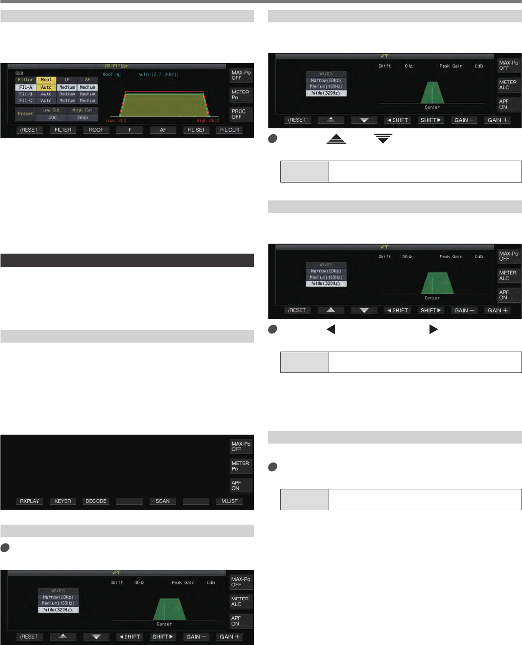
Preset Passband Characteristics
The frequently-used filter settings (high cut, low cut and WIDTH/
SHIFT) can be preset according to the style in which this
transceiver is used.
.
1Press [IF FIL] or F2 [FILTER] to select an RX filter.
2Press F6 [FIL SET].
The current filter settings (high cut, low cut and WIDTH/SHIFT)
are stored as the preset values.
•When preset values are applied, the values will be highlighted
in the display for approximately 0.5 seconds.
•Pressing F7 [FIL CLR] restores the passband width changed
using the [HI/SHIFT] and [LO/WIDTH] controls to the preset
value.
Audio Peak Filter in the CW Mode
During reception in the CW mode, if the signal intelligibility
deteriorates due to noise or other reasons, allowing the RX signal
to pass through the bandwidth with the pitch frequency as the
center frequency helps to improve the intelligibility of the RX signal.
Turning ON/OFF Audio Peak Filter
1Select CW mode.
2Press F [APF].
•Pressing F [APF] each time toggles the audio peak filter of
the selected band between ON and OFF.
•When audio peak filter is on, “ON” is displayed on the key
guide. “OFF” is displayed when the audio peak filter is turned
off.
.
Displaying the Audio Peak Filter Screen
Press and hold F [APF] to display the audio peak
filter screen of the selected band.
.
Switching the Passband Characteristics
3 types frequency passbands are available for selection for the
audio peak filter.
.
Press F2[ ]/ F3[ ] to select a passband
width.
Setting
Value Wide (320Hz)/ Medium (160Hz) (default)/ Narrow
(80Hz)
Shifting the Passband Width
Shifting the passband width of the audio peak filter helps to avoid
interference with nearby frequencies.
.
Press F4[ SHIFT] or F5[SHIFT ], or turn the
[MULTI/CH] control to shift the passband width.
Setting
Value -200 to 0 (default) to +200 [Hz] (5-step)
•The shift amount of the passband width is ±200 Hz with the
pitch frequency as the center frequency.
•The selected passband width for the audio peak filter shifts
from the pitch frequency toward a higher or lower bandwidth.
Configuring the Peak Gain
To further enhance the target CW signal, raise the gain level.
Press F6 [GAIN +] or F7 [GAIN -] to adjust the gain
level.
Setting
Value 0dB (default) to +6dB
6 REJECTING INTERFERENCE
6-4
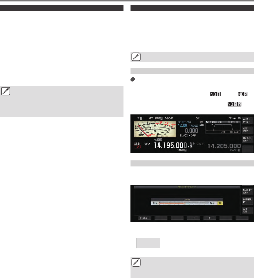
Audio Peak Filter in the FSK Mode
When receiving signals in the FSK mode, allowing both the mark
and space frequencies to have a peak help to reduce the
occurrence of garbled characters, thus improving the decodability.
This audio peak filter is compatible with the high tone (mark
frequency of 2125 Hz) as well as the low tone (mark frequency of
1275 Hz).
1Select FSK mode.
2Press F [APF].
•Pressing F [APF] each time toggles the audio peak filter of
the selected band between ON and OFF.
•When audio peak filter is on, “ON” is displayed on the key
guide. “OFF” is displayed when the audio peak filter is turned
off.
●When the shift width in RTTY exceeds 170 Hz, the audio
peak filter for the selected band cannot be set to ON.
●Internally demodulated signals are not processed for the
audio filter in the FSK mode.
●The passband cannot be shifted for the audio peak filter
in the FSK mode.
Noise Blanker
The noise blanker is used to reduce pulse noise. This transceiver
is equipped with two types of noise blankers: NB 1 that employs
analog signal processing and NB2 that performs DSP (digital
signal processing) at the IF level. Furthermore, two types of NB2
with different operating principles are available for selection. NB1
and NB2 can be selected for use according to the noise conditions.
They can also be employed at the same time.
●Noise blanker cannot be used in the FM mode.
Turning ON/OFF Noise Blanker 1/2
Press [NB1] or [NB2].
Pressing [NB1] or [NB2] each time toggles noise blanker 1 and
noise blanker 2 respectively between ON and OFF.
•When noise blanker 1 or 2 is ON, << >> or << >>
is displayed on the screen.
•When both noise blanker 1 and 2 are ON, << >> is
displayed on the screen.
.
Adjusting the NB1 Level
1Press and hold [NB1] to display the Noise Blanker
1 configuration screen.
.
2Press F4 [–] or F5 [+], or turn the [MULTI/CH] control
to change the level.
Setting
Value 1 to 10 (default) to 20 (1 step)
•Configuring to a larger value reduces the noise further.
●Configuring to a value with a higher level of noise blanker
effect may cause the transceiver to malfunction and
distort the RX audio depending on the condition of the
RX signal or interfering signal.
REJECTING INTERFERENCE 6
6-5
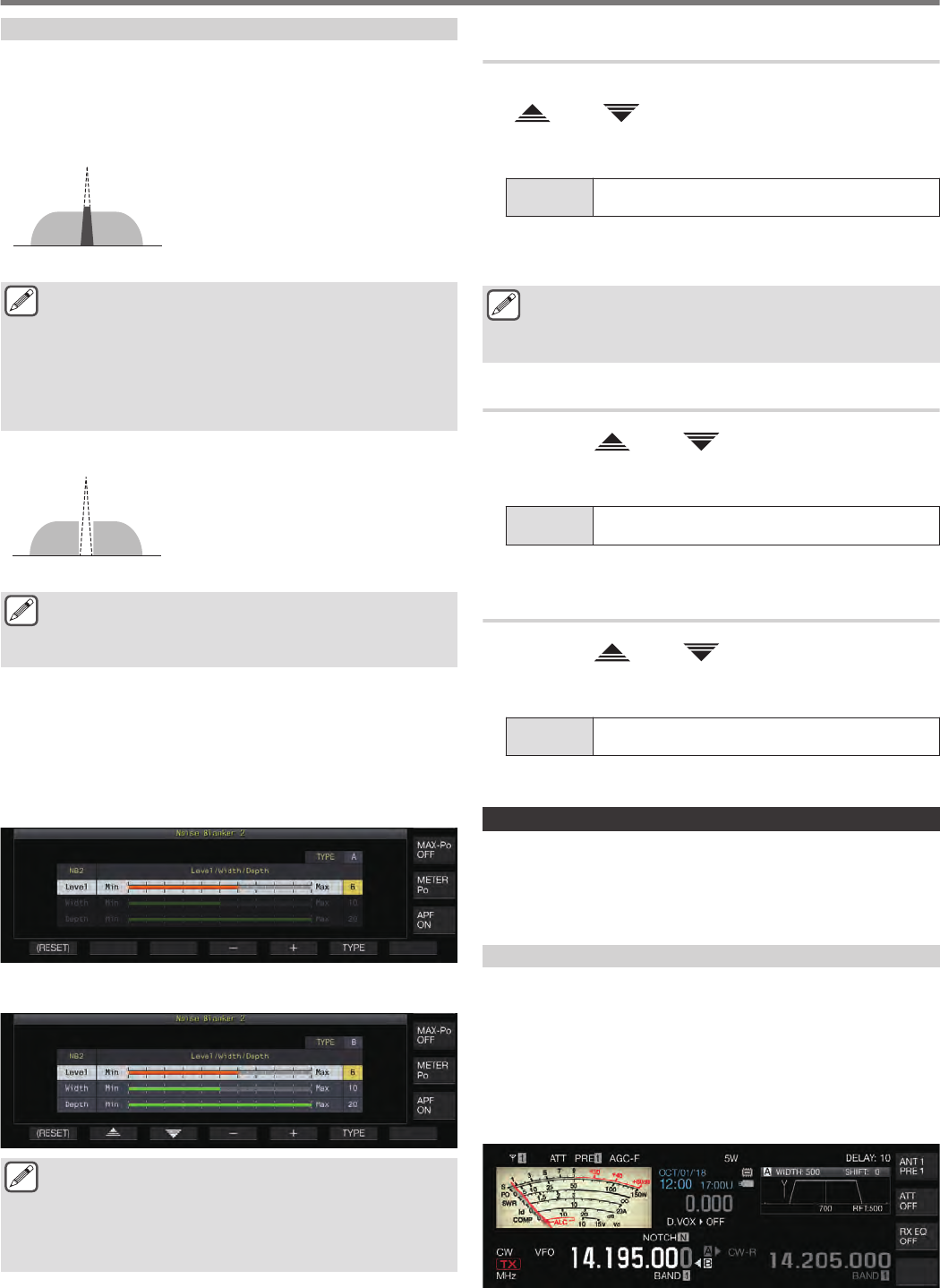
NB2
NB2 is a function for blanking pulse noise with a long pulse width
which cannot be blanked by NB1. NB2 is further divided into Type
A and Type B, which can be employed according to the
circumstances. NB2 can also be used together with NB1.
Type A
.
Type A suppresses mainly the pulse noise
without blanking the target signal. The level
of the effect (Level) can be adjusted.
Type A
Target Signal
Pulse Noise
●As pulse noise remains after blanking when “Type A” is
used, pulse noise might be audible when the target
signal is strong or when there is strong interference
within the passband. Even in such a situation, it has the
effect of bringing up the target signal when AGC gain is
low due to pulse noise.
●“Type A” is most effective in cases where weak target
signals are buried in strong pulse noise.
Type B
.
Target Signal
Pulse Noise As with NB1, Type B blanks the pulse noise
together with target signal. The pulse
sensitivity level (Level), blanking duration
(Width) and attenuation level (Depth) can
be adjusted.
Type B
When pulse noise with a long pulse width is blanked using
“Type B”, the time interval for which the target signal is
removed becomes longer due to the long blanking time,
and this causes the silence period to stand out.
1Press and hold [NB2] to display the Noise Blanker
2 configuration screen.
2Press F6 [TYPE].
Pressing F6 [TYPE] each time toggles the screen between
“Type A” and “Type B”.
Type A Screen
.
Type B Screen
.
●Pressing and holding [NB2] displays the noise blanker
2 screen which shows the current type in use.
●The default setting is “Type A”.
●Type selection is separately available for audio mode
(SSB/AM (including DATA mode)) and non-audio mode
(CW/FSK/PSK).
Configuring the NB2 Effect Level (Type A)/ NB2 Pulse
Sensitivity Level (Type B)
1While the Type B screen is displayed, press F2
[]/ F3 [ ] to select “Level”.
2Press F4 [–]/ F5 [+] or turn the [MULTI/CH] control
to change the level.
Setting
Value 1 to 6 (default) to 10 (1 step)
•Type A: Configuring to a larger value reduces the noise further.
•Type B: Configuring to a larger value blanks the RX signal
and pulse noise with small difference in signal level.
●Configuring to a value with a higher level of noise blanker
effect may cause the transceiver to malfunction and
distort the RX audio depending on the condition of the
RX signal or interfering signal.
Configuring the Blanking Duration (Type B Only)
1Press F2 [ ]/ F3 [ ] to select “Width”.
2Press F4 [–]/ F5 [+] or turn the [MULTI/CH] control
to change the blanking duration.
Setting
Value 1 to 10 (default) to 20 (1 step)
•Configuring to a larger value lengthens the blanking time.
Configuring the NB2 Attenuation Level (Type B Only)
1Press F2 [ ]/ F3 [ ] to select “Depth”.
2Press F4 [–]/ F5 [+] or turn the [MULTI/CH] control
to change the attenuation level.
Setting
Value 1 to 20 (default) (1 step)
•Configuring to a larger value increases the attenuation level.
Notch Filter
Notch filter is capable of suppressing beat interference at the IF level.
It can be employed to eliminate beat noise and bring up weak
signals or during operation while checking the noise condition.
The notch filter can be used in the SSB, CW, FSK, PSK and AM modes.
Turning ON/OFF Notch Filter
1Press [NCH].
Pressing [NCH] each time toggles the notch filter between ON
and OFF.
•When the notch filter is ON, “NOTCH” is displayed on the
screen.
•When notch filter is ON, an indicator showing the notch point
is displayed in the RX filter passband characteristics inside
the filter scope.
.
2Turn the [NOTCH] control.
Adjust the notch frequency to the point where beat or
interference is to be suppressed.
6 REJECTING INTERFERENCE
6-6
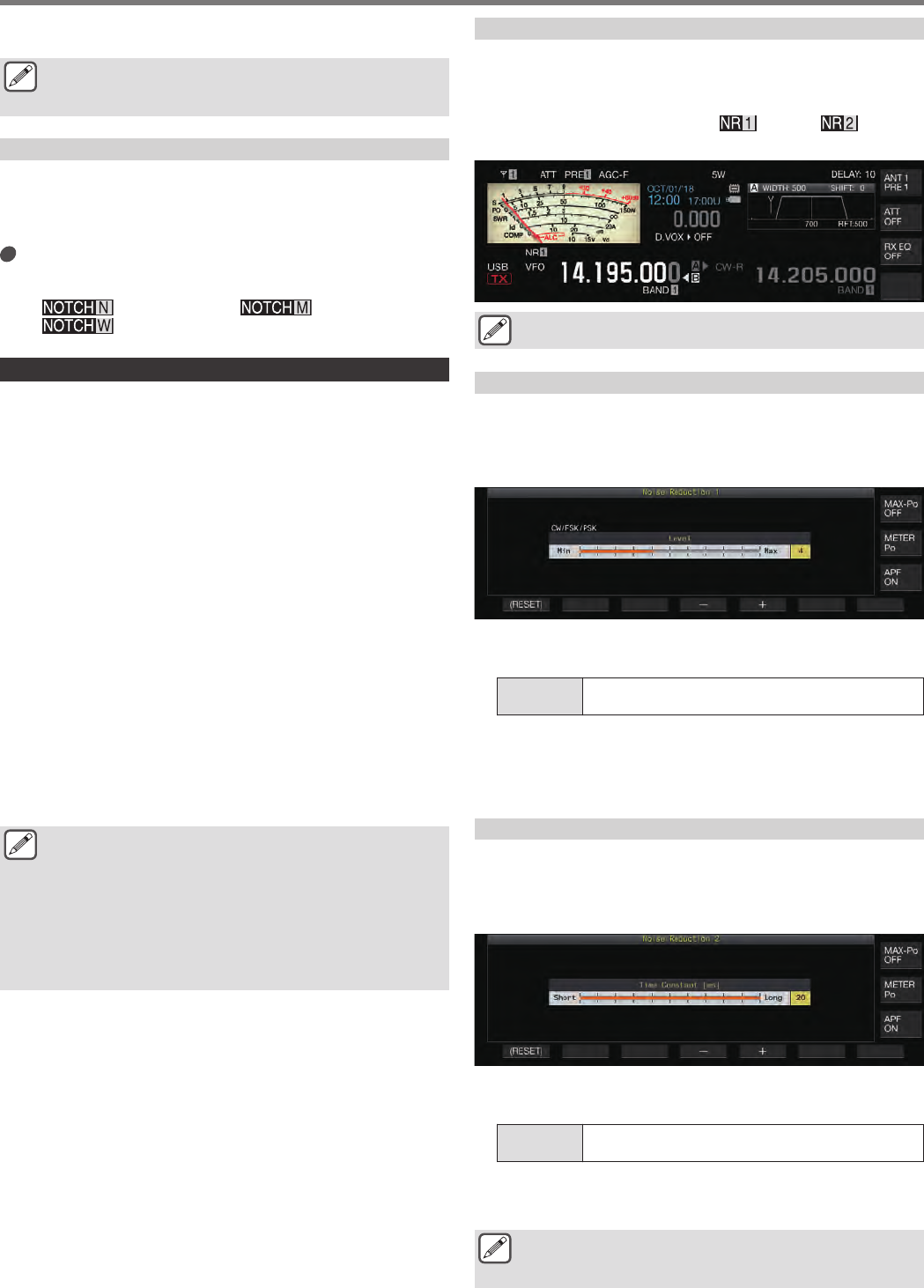
•The notch point indicator moves as the notch frequency
changes.
●Once the notch point has been set in the CW mode,
altering the PITCH and SHIFT values will not change the
notch point set for beat suppression.
Switching the Notch Filter Bandwidth
The bandwidth of the stopband for the notch filter can be
configured to normal, middle or wide. The middle and wide
stopbands are wider than the bandwidth of the normal stopband
by two and three times respectively.
Press and hold [NCH].
Pressing and holding [NCH] each time switches the bandwidth
and changes the display as follows.
<< >> (Normal) → << >> (Middle) →
<< >> (Wide)
Noise Reduction
This transceiver comes with two types of noise reduction functions
NR1 and NR2 which are effective for reducing continuous noise.
When NR1 is used, the optimal method is activated according to
the mode in use.
Noise Reduction 1 (NR1)
•In the SSB, FM and AM modes, noise reduction uses a
spectrum subtraction system that places focus on the clarity.
•In the CW, FSK and PSK modes, noise reduction employs an
LMS filter system that emphasizes the periodic signal.
•The noise reduction effect for NR1 can be adjusted.
Noise Reduction 2 (NR2)
•NR2 employs an SPAC system for all modes which extracts the
periodic signal. This system detects periodic signals that are
contained in the RX signals, connects the detected periodic
signals and plays them as part of the RX audio. For this reason,
this method is effective for signals with a single frequency such
as CW signals.
•NR2 allows configuration to the optimal RX conditions by
varying the autocorrelation time for periodic signal detection.
•NR2 is most effective in the CW mode. (Use of NR1 is
recommended for modes other than CW.)
●Beat signals are also suppressed when NR1 is used in
the SSB, FM and AM modes as it suppresses stationary
signals. This is a theoretical behavior and not a
malfunction.
●When NR2 is set to ON in the SSB mode, the signal
clarity may deteriorate, or pulse noise or distortion may
occur. This is a theoretical behavior and not a
malfunction.
●NR2 cannot be used in the FM mode.
Turning ON/OFF Noise Reduction
1Press [NR].
Pressing [NR] each time toggles the option in the following
sequence: “NR1” → “NR2” → “OFF”.
•When NR1 or NR2 is ON, << >> or << >> is
displayed on the screen.
.
●NR1 and NR2 cannot be turned on at the same time.
Configuring the NR1 Effect Level
1Press [NR] to select Noise Reduction 1.
2Press and hold [NR] to display the Noise Reduction
1 effect level configuration screen.
.
3Press F4 [–]/ F5 [+] or turn the [MULTI/CH] control
to change the level of effect.
Setting
Value 1 to 5 (default) to 10 (1 step)
•For NR1, configuring to a larger value reduces the noise
further. However, as the impact on the RX audio also gets
stronger if the effect level is excessively high, adjust it to an
appropriate level.
Configuring the NR2 Correlation Time
1Press [NR] to select Noise Reduction 2.
2Press and hold [NR] to display the NR2 Time
Constant configuration screen.
.
3Press F4 [–]/ F5 [+] or turn the [MULTI/CH] control
to change the correlation time.
Setting
Value 2 to 20 (default) [ms] (2-step)
•As the optimal correlation time varies with the RX signal and
noise type when NR2 is used, configure the correlation time
while receiving the signals.
●NR2 adjusts the correlation time for periodic signal
extraction. It is different from NR1, which adjusts the
effect level.
REJECTING INTERFERENCE 6
6-7
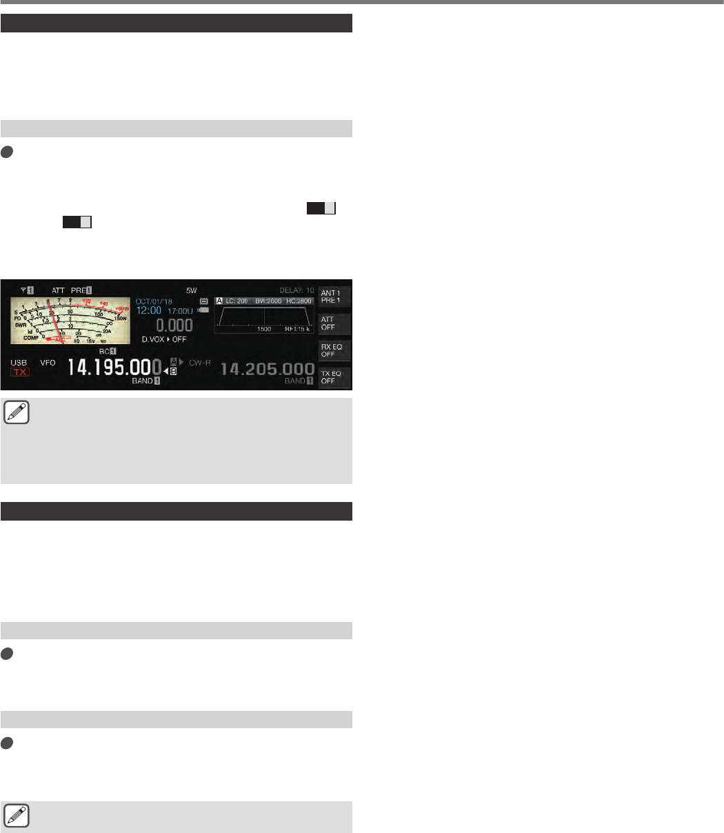
Beat Canceler
Beat canceler is capable of suppressing multiple periodic
interfering signals (beats) within the RX bandwidth through digital
processing at the AF level.
This function can be used in the SSB, AM and FM modes.
Turning ON/OFF Beat Canceler
Press [BC].
Pressing [BC] each time switches the beat canceler mode in
the following sequence: “Beat Canceler 1” → “Beat Canceler 2”
→ “OFF”.
•When beat canceler 1 or beat canceler 2 is ON, <<
BC 1
>>
or <<
BC 2
>> is displayed on the screen.
•Beat canceler 1 suppresses weak beats and continuous
beats. Beat canceler 2 suppresses intermittent beats such
as CW signals.
.
●Although the beat canceler suppresses the overall
auditory beat, the gain of the target signal cannot be
recovered using the AGC function. Thus, if the beat
signal is larger than the target signal, using a notch filter
activates the AGC function to enhance the clarity of the
target signal.
DSP Monitor
DSP monitor is a function for temporarily expanding the passband
width of the IF filter and AF filter via DSP in order to monitor the
signal condition of nearby frequencies such as when receiving a
specific frequency using a filter with a narrow passband width
during contesting.
Assigning DSP Monitor to PF Key
Register “DSP MONITOR” in Menu [0-15] “PF A: Key
Assignment” to Menu [0-31] “Microphone UP: Key
Assignment”
Expanding the Passband Width Using DSP Monitor
Press and hold down the PF key that is assigned
with the DSP monitor function.
The passband width of the filter is expanded while the key is
held down.
●During DSP monitoring, the audio peak filter is forcibly
turned OFF.
6 REJECTING INTERFERENCE
6-8