JVC KENWOOD 512000 Scanning Receiver User Manual 3
JVC KENWOOD Corporation Scanning Receiver Users Manual 3
Contents
- 1. Users Manual 1
- 2. Users Manual 2
- 3. Users Manual 3
- 4. Users Manual 4
Users Manual 3
Bandscope
With the signal strength represented on the vertical axis and
frequency on the horizontal axis, the bandscope provides a visual
representation of the condition of the RX frequency band.
•The bandscope comes in the following 3 modes.
Center mode: A mode where the center of the horizontal axis
represents the RX frequency.
Fixed mode: A mode where the lower and upper frequency
limits of the frequency band to be displayed are fixed.
Auto scroll mode: A mode where the scope range scrolls
automatically while maintaining the span when the lower or
upper limit of the marker scope range is exceeded.
•By displaying a waterfall below the bandscope display, the RX
frequency, surrounding conditions as well as transition in the
signal strength can be viewed.
•The vertical axis of the waterfall display represents time while
the horizontal axis represents frequency.
•Signal strength is represented in a spectrum in the order of white
(strong), red to yellow (medium) and green to blue (weak). The
color changes according to the strength of the signal to be
observed.
•The speed of the waterfall drop can be adjusted.
•When the waterfall is displayed, the height of the bandscope
display is reduced to one-third of the original size.
•The filter passband is constantly represented by a translucent
display in the bandscope.
●“OVF” is displayed when excessive signal is received. In
this case, configure an attenuator for the bandscope.
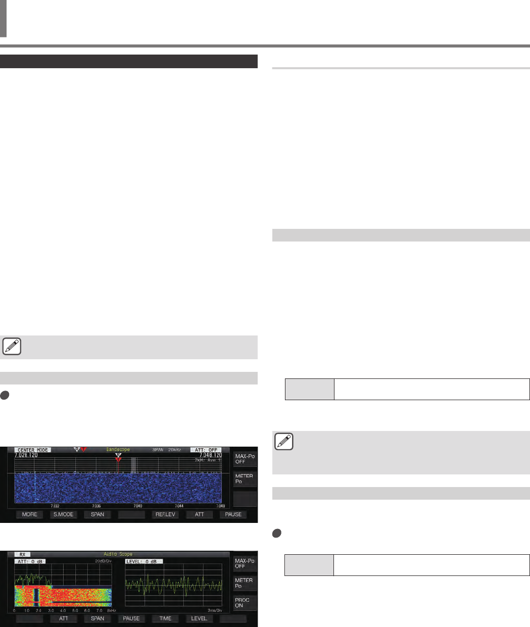
Displaying the Bandscope
Press [SCP] to display the scope screen.
Pressing and holding [SCP] each time toggles the display
between “Bandscope” and “Audio Scope”.
Bandscope
.
Audio Scope
.
Switching the Bandscope Display Type
1Display the bandscope.
2Press [SCP].
Pressing [SCP] each time switches the selection in the
following sequence.
“(Standard size) Bandscope + Waterfall”
↓
“(Enlarged size) Bandscope + Waterfall”
↓
“(Standard size) Bandscope”
↓
No scope display (ends scope display)
•While a bandscope is displayed, pressing [ESC] ends the
bandscope display.
Adjusting the Reference Level
If there is difficulty distinguishing the target signal from the noise
when there is significant noise or when observing weak signals
when there is little noise, the reference level of the bandscope can
be adjusted to ease identification of the target signal.
1Press F5 [REF.LEV] to display the setting value of
the reference level at the center of the bandscope
screen.
•If F5 [REF.LEV] is not displayed, press F1 [MORE].
2Turn the [MULTI/CH] control to adjust the reference
level while observing the bandscope waveform and
waterfall spectrum on the bandscope screen.
Setting
Value -20 to 0 (default) to +10 dB (0.5 dB step)
3Press F5 [REF.LEV] to end adjustment of the
reference level.
●If the target signal cannot be identified on the bandscope
screen even after adjusting the reference level due to the
excessively high input signals, switch to a different
attenuator for the bandscope.
Configuring the Speed of Waterfall Drop
The speed at which the waterfall is flowing can be selected from
the options available.
Press F4 [SPEED].
Pressing F4 [SPEED] each time switches the flow speed.
Setting
Value Speed1/ Speed2/ Speed3/ Speed4 (default)
•After altering the speed, “Speed n” is displayed in the
waterfall area for about 1 second.
•Pressing and holding F4 [SPEED] switches the options in
the reverse sequence.
SCOPE FUNCTIONS 7
7 SCOPE FUNCTIONS
7-1
Waterfall Display during Tuning (Center Mode)
This is a function for switching the behavior of the waterfall display
when the frequency is changed.
Configure in Menu [8-03] “Waterfall when Tuning
(Center Mode)”
Setting
Value Straight (default)/ Follow
Straight: Uses a straight line to show transition in the level of
the target signal displayed on the waterfall when the frequency
is altered.
Follow: Tracks and displays the latest FFT level at the portion
where the waterfall starts flowing when the frequency is altered.
Reduced Bandscope Display
A small bandscope (with a waterfall display) can be displayed on
screens such as those for the different settings, RTTY
communication and PSK communication.
1Display the menu, configuration modes except
equalizer configuration and the RTTY/PSK
communication screen.
2Press [SCP].
A small bandscope is displayed.
.
●While the reduced bandscope is displayed, the
horizontally arrayed F keys are switched to the function
keys of the configuration screen and thus the bandscope
settings cannot be changed.
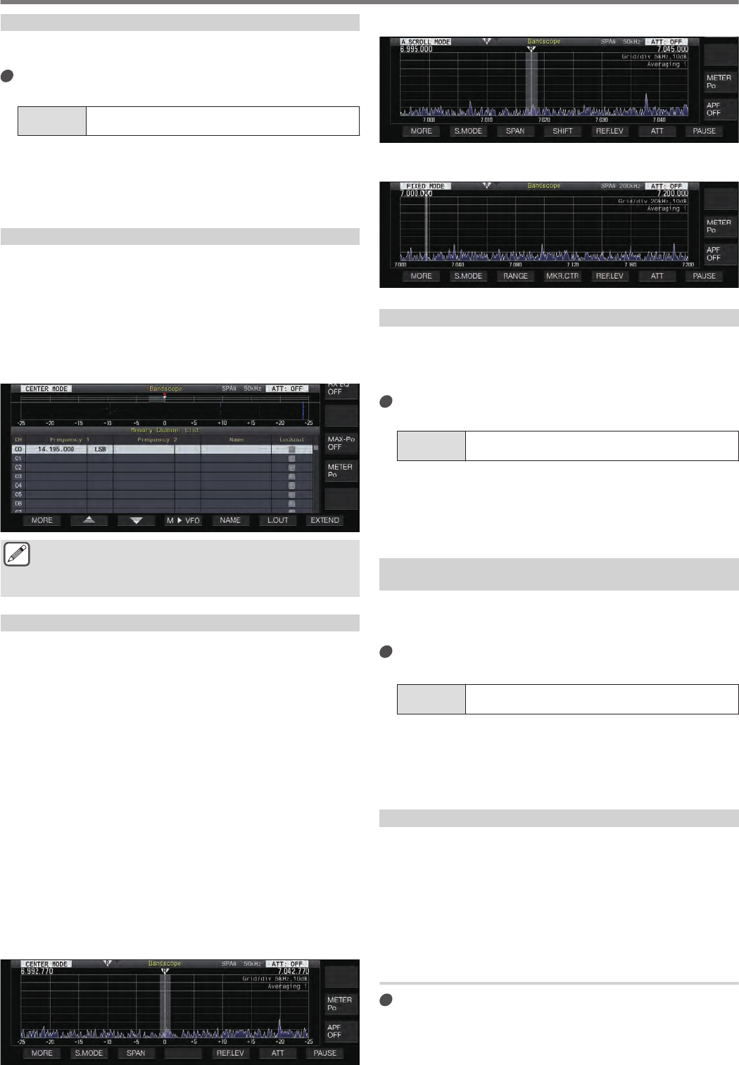
Switching the Scope Display Mode
1Display the bandscope screen.
2Press F2 [S.MODE].
Pressing F2 [S.MODE] each time switches the selection to
“Center Mode”, “Auto Scroll Mode” and “Fixed Mode” in
sequence. If [S.MODE] is not displayed, press F1 [MORE].
Center Mode (CENTER MODE)
Displays a bandscope with the display frequency as the center
at all times.
Auto Scroll Mode (A.SCROLL MODE)
The basic behavior is the same as that of the Fixed mode,
except that the scope range scrolls automatically while
maintaining the span when the marker (tuning frequency)
exceeds the lower or upper limit of the scope range.
Fixed Mode (FIXED MODE)
The scope range is fixed for each of the amateur bands, and
the operating frequency is displayed with a marker.
Center Mode
.
Auto Scroll Mode
.
Fixed Mode
.
Switching the Display Frequency Span
When the bandscope is displayed in the Center mode or Auto
Scroll mode, the display frequency span (the width between the
lower and upper frequency limits in the bandscope screen) can be
adjusted.
Press F3 [SPAN].
Pressing F3[SPAN] each time switches the frequency span.
Setting
Value ±2.5kHz/ ±5kHz/ ±10kHz/ ±15kHz/ ±25kHz (default)/
±50kHz/ ±100kHz/ ±250kHz
•Pressing and holding F3[SPAN] each time switches the
options in the reverse sequence.
•The selected display frequency span is displayed in the
toolbar of the bandscope screen as “SPAN 50kHz”, for
example.
Selecting Relative or Absolute Frequency Display for
the Grid (Center Mode)
During carrier point center display in the Center mode, the mode
of frequency scale display at the bottom of the bandscope can be
switched to one of the options available.
Configure in Menu [8-06] “Frequency Scale (Center
Mode)”
Setting
Value Relative Frequency (default)/ Absolute Frequency
Relative Frequency: The frequency scale display at the
bottom of the scope area represents the relative frequency from
the center of the scope.
Absolute Frequency: The frequency scale display at the
bottom of the scope area represents the absolute frequency.
Marker Shift
This function shifts the scope range in the auto scroll mode
operation so that the marker is displayed at a position that makes
observation easier.
Shifting the marker to the left edge in the upper frequency
transmitted by the DX station as well as in digital communication
will widen the display area of the bandscope. Making it easier to
determine the TX frequency and to observe in the various digital
modes.
Shifting the Marker
Press F2 [SHIFT].
The marker shifts to the preset shift position.
7 SCOPE FUNCTIONS
7-2
Changing the Shift Position of Marker Shift
1Press and hold F2 [SHIFT].
The transceiver enters the shift position configuration mode.
The value indicating the position of the selected vertical grid
line is displayed.
2Move the shift position to the desired position using
the [MULTI/CH] control.
•Pressing and holding F [SHIFT] moves the shift position to
the center.
3Press F [SHIFT].
The transceiver exits the shift position configuration mode.
●Depending on the relationship between the RX
frequency and the span, deviation of 1 grid to the left or
right may occurred in the shift operation.
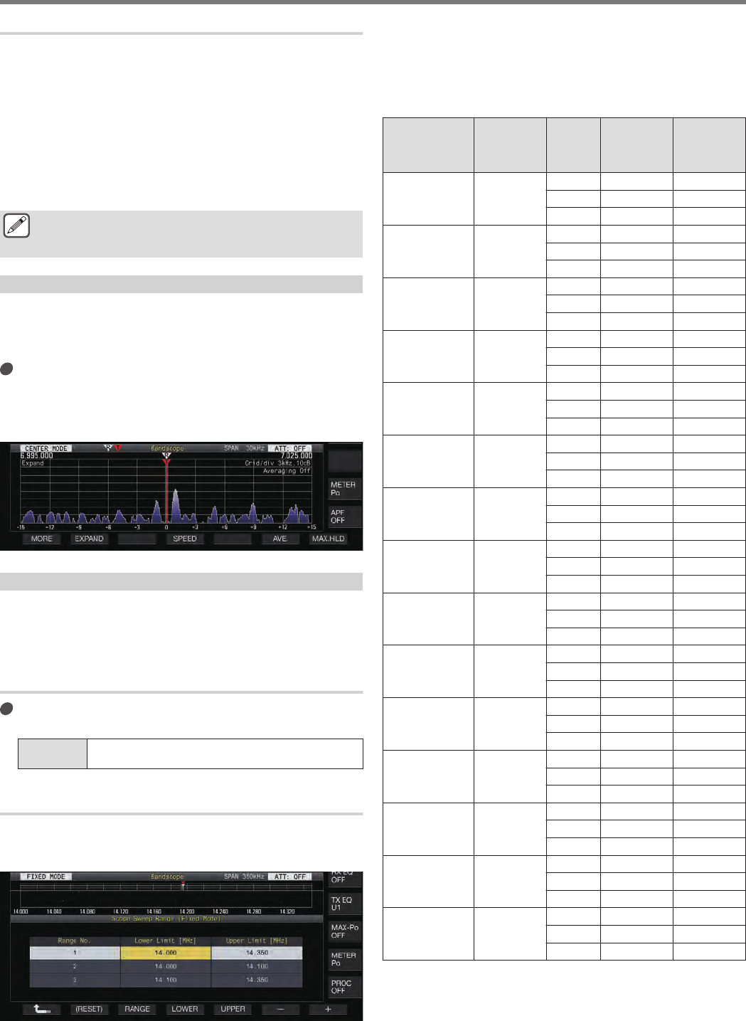
Expand
This function expands the frequency range for spectral analysis while
in the center mode (when the waterfall display during tuning is
configured to “Straight”) or auto scroll mode to prevent the waterfall
display from being interrupted when the frequency is changed.
Press F2 [EXPAND].
Pressing F2 [EXPAND] each time toggles the expand function
between ON and OFF.
•When the expand function is ON, “Expand” is displayed
below the lower frequency limit display.
.
Scope Range of Each Band (Fixed Mode)
The steps to configure the scope range for each of the amateur
bands when the bandscope is displayed in the Fixed mode are
described below. Three types of scope range are available for
selection for each band.
Switching the Scope Range
Press F3 [RANGE].
Pressing F3 [RANGE] each time switches the scope range.
Setting
Value Range No.1 (default)/ Range No.2/ Range No.3
Configuring the Scope Range
1Press and hold F3 [RANGE] to display the screen
for configuring the scope range in the Fixed mode.
.
2Press F3 [RANGE] to select the scope range “Range
No.1”, “Range No.2” and “Range No.3”.
3Press F4 [LOWER] or F5 [UPPER] to select the
frequency to adjust.
4Press F6 [–]/ F7 [+] or turn the [MULTI/CH] control
to select the frequency.
•Details of the configurable frequency range are shown in the
table below.
Band
Configurable
Frequency
Range
[MHz]
Range
No.
Default
Lower Limit
[MHz]
Default
Upper Limit
[MHz]
LF Band 0.03 ≦ f ≦
0.300
1 0.130 0.140
2 0.130 0.140
3 0.130 0.140
MF Band1 0.300 ≦ f ≦
0.522
1 0.470 0.480
2 0.470 0.480
3 0.470 0.480
MF Band2 0.522 ≦ f ≦
1.705
1 0.750 1.250
2 0.750 1.250
3 0.750 1.250
1.8 MHz Band 1.705 ≦ f ≦
2.00
1 1.800 2.000
2 1.800 1.864
3 1.840 2.000
3.5 MHz Band 2.00 ≦ f ≦
4.00
1 3.500 4.000
2 3.500 3.600
3 3.600 4.000
5 MHz Band 4.00 ≦ f ≦
6.00
1 5.000 5.500
2 5.000 5.500
3 5.000 5.500
7 MHz Band 6.00 ≦ f ≦
8.00
1 7.000 7.200
2 7.000 7.045
3 7.045 7.200
10 MHz Band 8.00 ≦ f ≦
11.00
1 10.100 10.150
2 10.100 10.130
3 10.130 10.150
14 MHz Band 11.00 ≦ f ≦
15.00
1 14.000 14.350
2 14.000 14.100
3 14.100 14.350
18 MHz Band 15.00 ≦ f ≦
20.00
1 18.068 18.168
2 18.068 18.110
3 18.110 18.168
21 MHz Band 20.00 ≦ f ≦
22.00
1 21.000 21.450
2 21.000 21.150
3 21.150 21.450
24 MHz Band 22.00 ≦ f ≦
26.00
1 24.890 24.990
2 24.890 24.930
3 24.930 24.990
28 MHz Band 26.00 ≦ f ≦
30.00
1 28.000 28.500
2 28.000 28.200
3 28.200 28.700
50 MHz Band 30.00 ≦ f ≦
60.00
1 50.000 50.500
2 50.000 50.100
3 50.100 50.300
70 MHz Band
(E Type) 30.00 ≦ f ≦
74.80
1 70.000 70.500
2 70.000 70.250
3 70.250 70.500
SCOPE FUNCTIONS 7
7-3
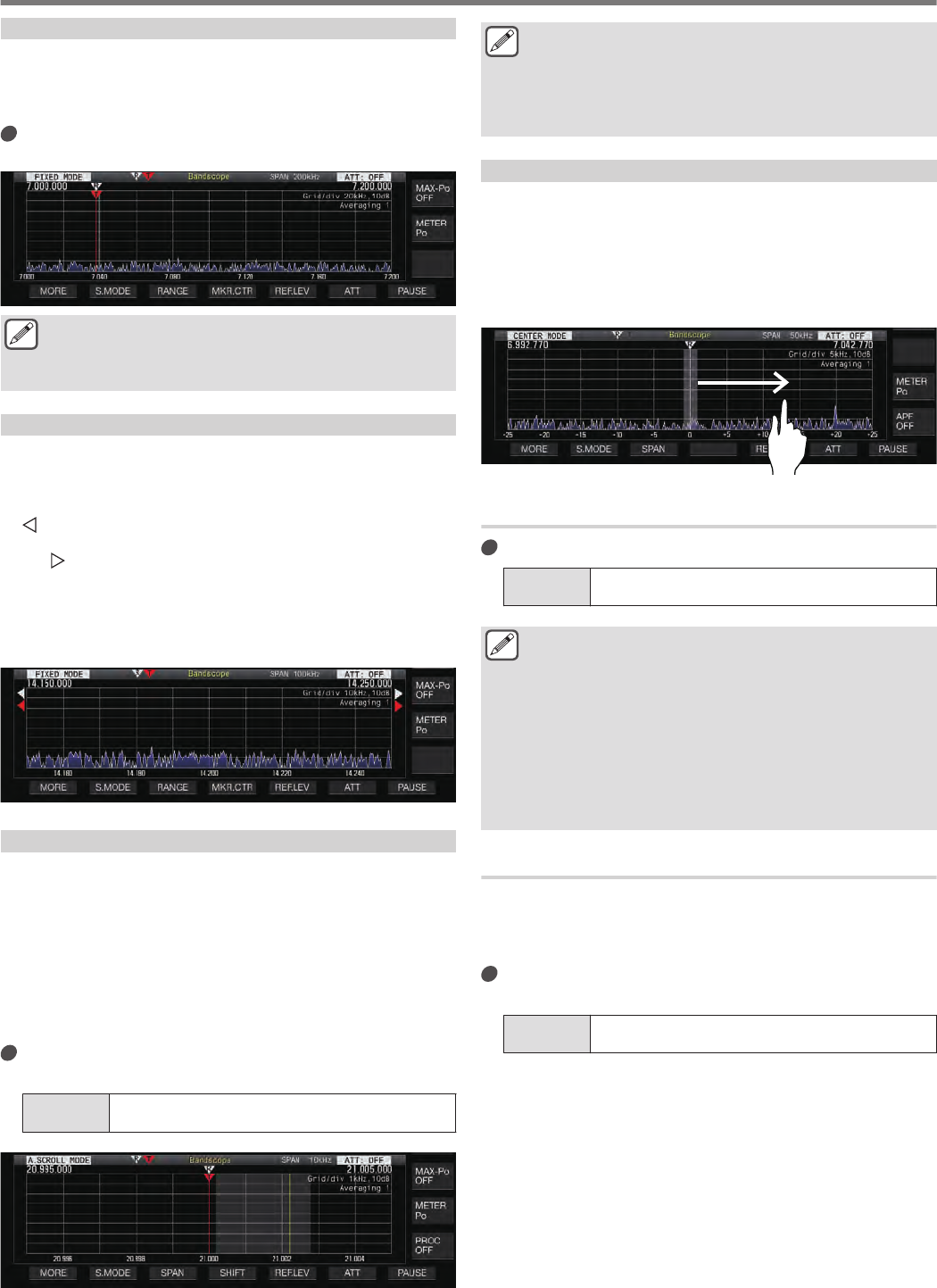
Marker Centering
The scope range can be shifted with the display frequency span
maintained such that the marker of the selected amateur band is
displayed near the center (within one grid to the left or right from
the center).
Press F4 [MKR.CTR].
The scope range is shifted with the frequency span maintained.
.
●Changes in the lower and upper frequency limits due to
the marker centering operation are temporary, and does
not alter the preconfigured lower and upper frequency
limits of the scope band in question.
Notification on Exceeding of Lower or Upper Limit
If the marker frequency falls outside the display range of the
bandscope when a frequency marker is displayed on the
bandscope in the Fixed mode, a display appears to inform the user
that the marker has moved out of the bandscope range.
A “ ” icon appears at the left edge of the bandscope screen if the
marker frequency value is smaller than the lower frequency limit,
and a “ ” appears at the right edge if the marker frequency value
is larger than the upper frequency limit.
The markers indicating that the lower or upper limit is exceeded
are color coded as follows.
White: RX frequency
Red: TX frequency
.
Displaying Tuning Assist Line (SSB Only)
This is a function for displaying a tuning assist line (yellow) in the
waterfall display area during operation in the SSB mode. When the
tuning assist line is displayed, the peak of the waveform is set near
this line.
For example, the frequency spectrum of a male voice is said to be
strongest near 500 Hz. In this case, displaying the tuning assist
line near a position shifted by 500 Hz from the carrier point of the
waterfall display area and allowing the part where strong signals
are flowing to overlap with the line helps to increase the probability
of zeroing in the target signal.
Configure in Menu [8-05] “Tuning Assist Line (SSB
Mode)”
Setting
Value Off (default)/ 300/ 400/ 500/ 600/ 700/ 800/ 1000/ 1500/
2210 [Hz]
.
●This function works in the Center mode only when Menu
[8-03] “Waterfall when Tuning (Center Mode)” is
configured to “Straight”.
●The tuning assist line is displayed on the upper side with
respect to the carrier point in the case of USB and on the
lower side in the case of LSB.
Touchscreen Tuning
This function enables signals to be received by touching the
desired point in the bandscope display area or waterfall display
area.
•When in the Center mode, touching a point sets the
corresponding frequency as the center frequency.
•When in the Fixed mode, touching a point moves the marker to
the corresponding frequency.
.
Turning ON/OFF Touchscreen Tuning
Configure in Menu [0-14] “Touchscreen Tuning”
Setting
Value Off/ On (default)
●The following operations are prohibited even when
touchscreen tuning is ON.
•When the frequency lock function is ON
•When the memory channels are empty or when
temporary change of memory channels is disabled
•When an area outside the frequency range of the
memory channel for specific band segments is
touched
•During transmission
•When the TX frequency is received by TF-SET while
only XIT is ON during simplex operation
Configuring the Gradation of the Waterfall
10 levels of gradation are available for configuring the waterfall
display.
To make it easy to find the weak signals, configure to a smaller
value to increase the sensitivity to color change.
Configure in Menu [8-04] “Waterfall Gradation
Level”
Setting
Value 1 to 7 (default) to 10 (1 step)
7 SCOPE FUNCTIONS
7-4
Touchscreen Tuning Correction
Touch and hold with a finger on the corresponding
point in the bandscope or waterfall display screen
where signal is to be received.
•Touching in the SSB/ CW/ FSK/ PSK mode changes the
correction behavior according to the “Touchscreen Tuning
Step Correction” setting in the menu.
•The CW auto tune function is activated after correction is
completed in the CW mode.
Step Correction
Configure the step correction operation during touchscreen tuning
in the SSB/ CW/ FSK/ PSK mode.
Configure in Menu [8-07] Touchscreen Tuning Step
Correction(SSB/ CW/ FSK/ PSK)
Setting
Value Off/On (default)
Marker Display
The positions of the TX and RX frequencies are indicated as
markers on the bandscope screen. This marker function allows the
checking of edge frequency on the bandscope by registering the
edge frequency of the contest or band plan.
During split operation, the TX frequency can be changed easily by
moving the TX frequency marker to the desired frequency while
monitoring the bandscope screen.
The frequency markers are color coded as follows.
White: RX Frequency
Red: TX Frequency
Registering a Marker
When a preferred frequency (up to 50 entries) is registered to the
frequency marker list, the registered frequency is indicated by a
marker on the bandscope (white dotted line).
1Press [MENU].
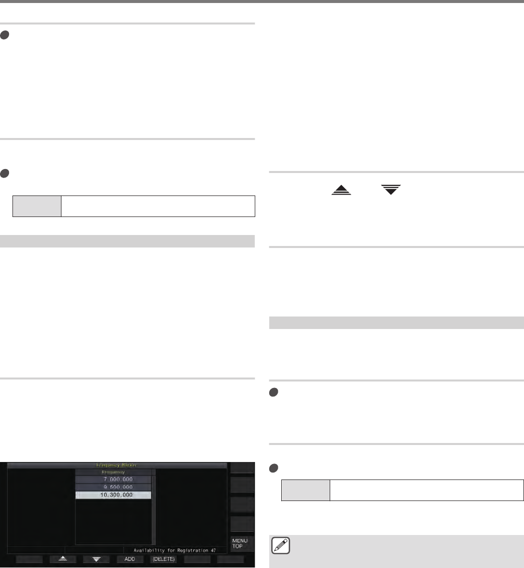
2Press and hold F [F.MKR] to display the Frequency
Marker list screen.
.
3Align with the frequency to register.
4Press F4 [ADD] to register.
•The current VFO frequency is added to the list.
•When RIT is ON, the display frequency with RIT added is
registered.
•The list is automatically sorted in ascending order starting
from the lowest frequency.
•If the frequency to be added is already registered, it will not
be registered twice and there will be no response even when
F4 [ADD] is pressed.
•If there are already 50 frequency entries in the list, the
frequency will not be registered and pressing F4 [ADD] will
have no response.
Deleting a Registered Frequency
1Press F2 [ ]/ F3 [ ] or turn the [MULTI/CH]
control to select the frequency to delete.
2Press and hold F5 [(DELETE)] to delete.
Turning ON/OFF Marker Function
1Press [MENU].
2Press F [F.MKR].
Pressing F [F.MKR] each time toggles the marker function
between ON and OFF.
Displaying the Maximum Value in the Waveform
The maximum value of the waveform shown on the bandscope
screen can be displayed to get a better grasp of the signal status.
Turning ON/OFF Maximum Value Display
Press F7 [MAX.HLD].
Pressing F7 [MAX.HLD] each time toggles the maximum value
display between ON and OFF.
Configuring the Hold Type
Select the method of displaying the maximum value of the waveform.
Configure in Menu [8-02] “Bandscope Maximum Hold”
Setting
Value 10 [s] (default)/ Continuous
10 [s]: Maximum value information is cleared after 10 seconds.
Continuous: Maximum value information is not cleared.
●The maximum value information is cleared automatically
if the RX frequency changes in the Center mode
regardless of the setting value selected.
SCOPE FUNCTIONS 7
7-5
Pausing the Waveform Display
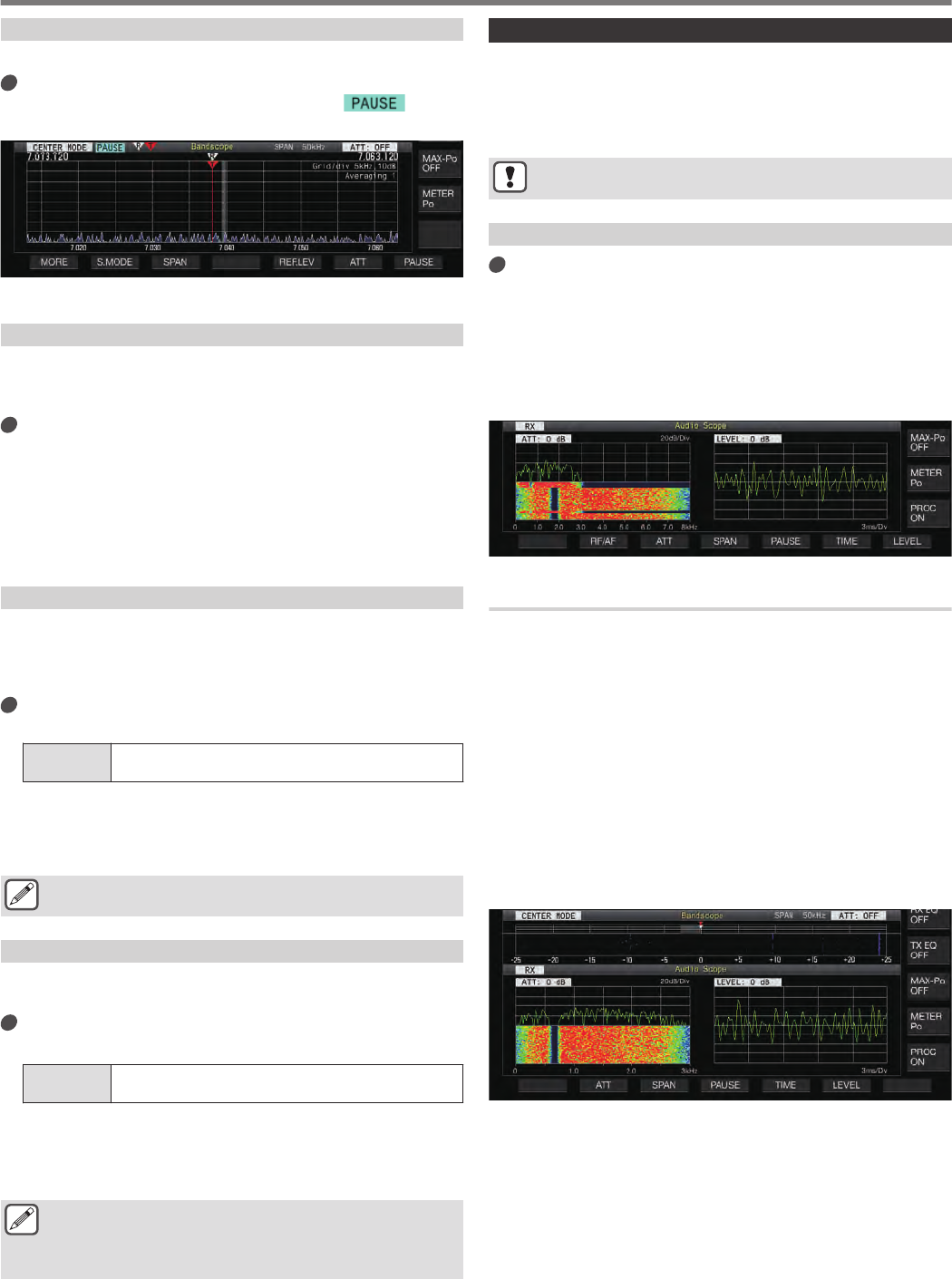
The waveform display on the bandscope screen can be paused.
Press F7 [PAUSE] to pause the waveform display.
•When the waveform display is paused, << >> is
displayed on the screen.
.
•Pressing F7 [PAUSE] again cancels the paused state.
Averaging of Bandscope Waveform
Averaging the bandscope waveform allows changes in the
waveform display to look smoother with continuous signals like
those of Morse signals which make observation easier.
Press F6 [AVE.] to switch the averaging level.
•Pressing F6 [AVE.] each time switches the selection in the
following sequence: “Off” (averaging disabled) → “1”
(minimum) → “2” → “3” (maximum) → “Off”. The averaging
level selected is displayed at the top right corner of the grid.
•Pressing and holding F6 [AVE.] each time switches the
options in the reverse sequence.
•The default setting is “1”.
Switching the Bandscope Attenuator
If the target signal cannot be identified on the bandscope screen
even after adjusting the reference level due to the excessively high
input signals, attenuate the input level to the bandscope by
switching to a different attenuator for the bandscope.
Press F6 [ATT] to switch to a different attenuator.
Pressing F6 [ATT] each time switches the attenuator.
Setting
Value Off (default)/ 10 dB/ 20 dB/ 30 dB
•Pressing and holding F6 [ATT] each time switches the
options in the reverse sequence.
•The current attenuator level setting is displayed at the top of
the bandscope.
Switching the attenuator for the bandscope does not affect
the RX sensitivity.
Displaying the TX Signal Waveform
A waveform for the TX signal can be displayed when a bandscope
for transmission is displayed in the Center mode.
Configure in Menu [8-00] “Bandscope Display
during TX”
Setting
Value Off (default)/ On
On: Displays the TX waveform in the bandscope while
transmission is in progress.
Off: Does not display the waveform in the bandscope while
transmission is in progress.
●The TX signal waveform cannot be displayed in the
Fixed mode.
●The setting for this function cannot be switched while
transmission is in progress.
Audio Scope
Two audio scope screen modes are available for selection: the
“audio scope screen” mode displays the waveform with an audio
bandscope + waterfall as well as an oscilloscope, while the “multi
scope screen” shows a reduced display of the bandscope at the
top together with the “audio scope screen”.
●“OVF” is displayed when excessive signal is received. In
this case, configure an attenuator for the audio scope.
Displaying the Audio Scope
Press and hold [SCP] to display the Audio Scope
screen.
Pressing and holding [SCP] each time toggles the display
between “Audio Scope” and “Bandscope”.
Audio Scope Screen
Left: Audio scope
Right: Oscilloscope
.
Switching the Audio Scope Display Type
1Display the Audio Scope screen.
2Press [SCP].
Pressing [SCP] each time switches the selection in the
following sequence.
“Audio Scope screen”
↓
“Multi Scope screen”
↓
No scope display (ends scope display)
Multi Scope Screen
Top: Reduced bandscope display
Left: Audio scope
Right: Oscilloscope
.
3Press [ESC] to end the display.
7 SCOPE FUNCTIONS
7-6
Switching the Audio Scope Attenuator
When the signal input level to the audio scope is excessively high,
attenuating the level helps to reduce the amplitude of the
waveform. Doing so optimizes the waveform display for easy
observation.
Press F2 [ATT].
Pressing F2 [ATT] each time switches the attenuator.
Setting
Value Off (default)/ 10 dB/ 20 dB/ 30 dB
•Pressing and holding F2 [ATT] each time switches the
options in the reverse sequence.
•The current attenuator level setting is displayed at the top of
the audio scope.
Switching the Display Frequency Span of the Audio
Scope
The display frequency span of the audio scope can be configured
to 3 kHz or 8 kHz. Configure the display frequency span to an
appropriate setting according to the filter band setting and
frequency to observe.
Press F3 [SPAN].
Pressing F3 [SPAN] each time toggles the span between “3
kHz (default)” and “8 kHz”.
.
Display when 8 kHz is selectedDisplay when 3 kHz is selected
Switching the Oscilloscope Level
Switching the input level of signals to the oscilloscope alters the
vertical amplitude of the waveform. Configuring the waveform
amplitude to an appropriate size helps to ease observation of the
waveform.
Press F6 [LEVEL].
Pressing F6 [LEVEL] each time switches the input level.
Setting
Value 0 dB (default)/ -10 dB/ -20 dB/ -30 dB
•Pressing and holding F6 [LEVEL] each time switches the
options in the reverse sequence.
•The current signal input level setting is displayed at the top
of the oscilloscope.
Switching the Sweep Time
Switching the sweep time of the oscilloscope alters the time range
of the oscilloscope display. The sweep time can be adjusted
according to the status of the signal to be observed.
Press F5 [TIME].
Pressing F5 [TIME] each time switches the sweep time.
Setting
Value 1 ms/ Div/ 3 ms/ Div/ 10 ms/ Div/ 30 ms/ Div/ 100 ms/
Div (default)/ 300 ms/ Div
•Pressing and holding F5 [TIME] each time switches the
options in the reverse sequence.
•The sweep time is displayed at the bottom of the
oscilloscope.
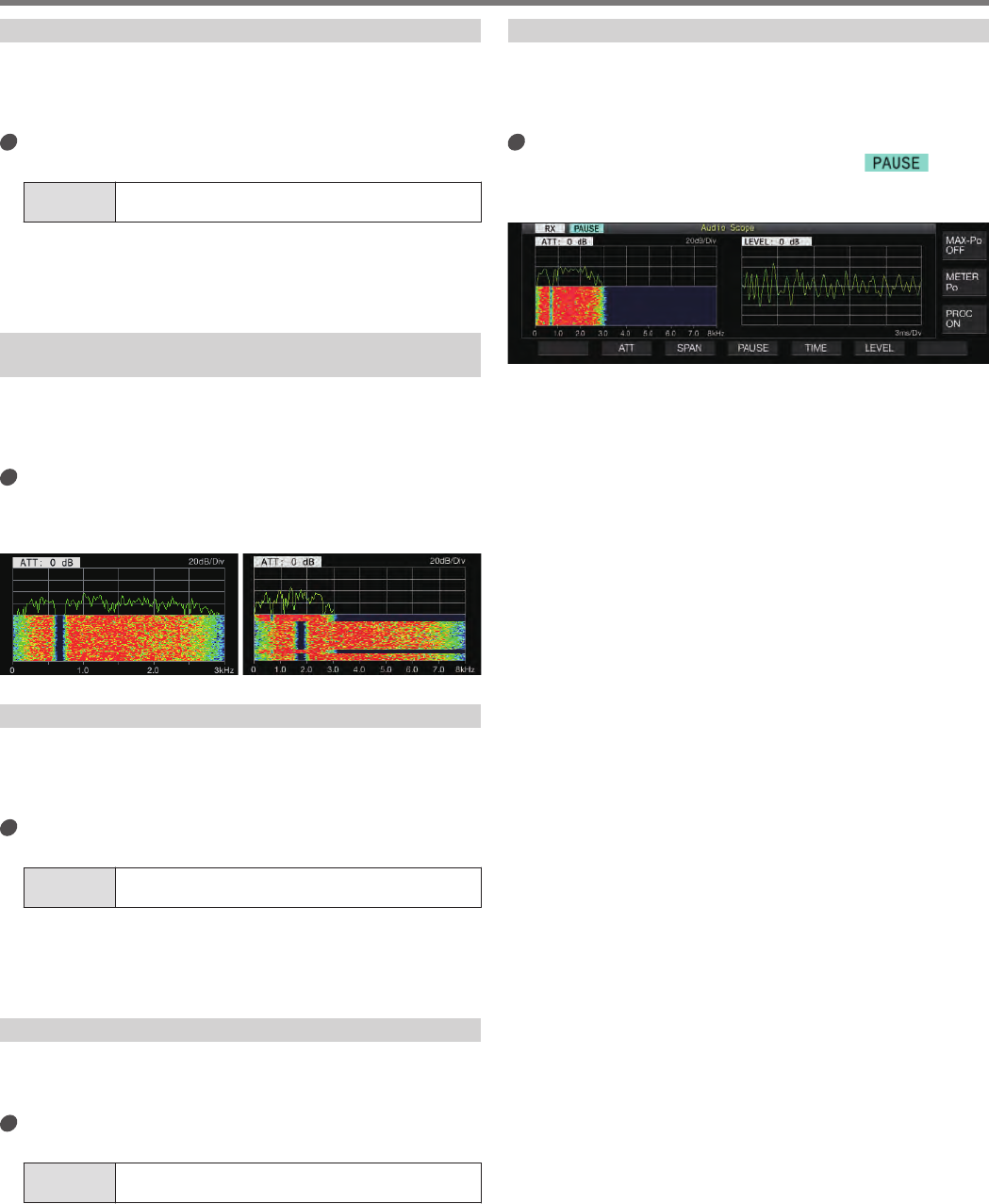
Pausing the Audio Scope
When the waveform displayed on the Audio Scope screen is
paused, the waveform is maintained until it is unpaused. The audio
scope can be paused to enable analysis of the waveform without
being interrupted whenever the display is refreshed.
Press F4 [PAUSE] to pause the waveform display.
•When the waveform display is paused, << >> is
displayed on the screen.
•Pressing F4 [PAUSE] again cancels the paused state.
.
SCOPE FUNCTIONS 7
7-7

.
7-8
Configuration of the Input Path of TX Audio
The method for transmitting the audio source that is input to the
MIC connector on the front panel as well as the ACC 2, (USB-B)
and LAN connectors on the rear panel of this transceiver can be
configured.
Audio
Source
Input Description
MIC Inputs the microphone audio when MIC is set to ON.
ACC 2 Inputs audio signal from the device connected to the ACC
2 connector when ACC 2 is set to ON.
USB Audio Inputs audio signal from the connected PC when USB
Audio is set to ON.
LAN Inputs audio signal from the audio device connected via
LAN when LAN is set to ON.
Switching the Audio Source Input
The steps to configure the audio (audio source input) to transmit
via PTT/SS/SEND and DATA PTT/DATA SEND are as follows.
•A separate setting can be configured when DATA mode is in
the OFF and ON status.
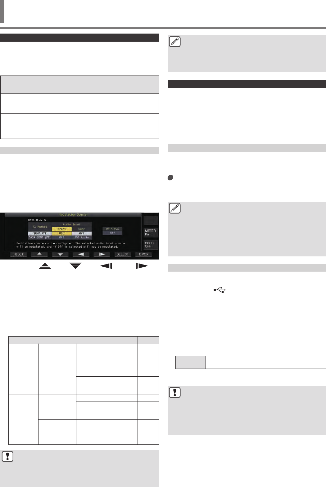
1Press and hold [DATA] to display the audio source
input screen.
The current ON/OFF status of the DATA mode at the
transmitting end is displayed at the top left corner.
.
2Press F2 [ ], F3 [ ], F4 [ ] or F5 [ ] to
select the method of transmission (“SEND/PTT” or
“DATA SEND (PF)”) and audio input line (“Front” or
“Rear”).
3Press F6 [SELECT] or turn the [MULTI/CH] control
to change the setting value.
•Pressing and holding F1 [(RESET)] restores both audio
input settings of the selected method of transmission to the
default values.
•The default setting varies as follows when DATA mode is in
the ON and OFF status.
Setting Item Setting Value Default
DATA OFF
SEND/ PTT
Front Off/ MIC MIC
Rear Off/ ACC 2/
USB Audio/
LAN Off
DATA SEND
(PF)
Front Off/ MIC Off
Rear Off/ ACC 2/
USB Audio/
LAN ACC 2
DATA ON
SEND/ PTT
Front Off/ MIC MIC
Rear Off/ ACC 2/
USB Audio/
LAN Off
DATA SEND
(PF)
Front Off/ MIC Off
Rear Off/ ACC 2/
USB Audio/
LAN
USB
Audio
●Note that some setting combinations might trigger
unintended transmission by this transceiver. Also, when
this transceiver is connected to a PC or another audio
source via USB audio, LAN or ACC 2 and when DATA
VOX is ON, sound that is emitted by the audio source
might trigger transmission by this transceiver.
●These are common settings for the SSB, AM and FM
modes. Although settings can also be changed during
operation while the operation mode at the transmitting
end is configured to CW, PSK or FSK, the settings that
are displayed on the screen are those when DATA mode
is in the OFF status.
VOX (Voice-Operated Transmit)
VOX (voice) is a function that automatically starts transmission
when the user speaks into the microphone and returns to the
receiving status when voice input stops. After speaking into the
microphone, insert a short pause before returning to the receiving
status.
•For Data VOX, data that is input from an audio source other than
the MIC connector can also be transmitted in the same way.
Turing ON/OFF VOX Function
The VOX function switches automatically between transmission
and reception based on audio input from the microphone in the
SSB, FM or AM mode.
Press [VOX].
Pressing [VOX] each time toggles the VOX function between
ON and OFF.
When the VOX function is ON, the [VOX] LED lights up in green.
●During transmission using the VOX function, audio input
from the microphone is transmitted regardless of the
audio source input settings.
●If transmission and reception are not performed automatically
when the VOX function is set to ON, try adjusting the VOX gain
level, increasing the distance between the microphone and the
speaker, move closer to the microphone when speaking or turn
down the volume level for incoming calls. If the above methods
do not work, use a headphone.
Selecting Audio Source Input for Data VOX
The transmission status can be activated automatically when data
audio beyond a certain level is input from the ANI terminal of the
ACC 2 connector, (USB-A or USB-B) or LAN connector on
the rear panel of this transceiver in the SSB, FM or AM mode. This
function is known as Data VOX.
The audio source input that is activated with the Data VOX function
can be switched using the steps below.
1Press and hold [DATA] to display the audio source
input screen.
2Press F7 [D.VOX].
Pressing F7 [D.VOX] each time switches the Data VOX audio
source.
Setting
Value Off (default)/ ACC 2/ USB Audio/ LAN
•“OFF”, “ACC 2”, “USB” or “LAN” is displayed to the right of
“D.VOX” at the top of the screen.
●If this transceiver is left connected to an audio source
such as a PC when Data VOX is configured to an audio
source input setting other than “OFF”, this transceiver
may be placed in the transmission state by the signals
from the audio source.
●When this transceiver is to be left connected to the audio
source, set the Data VOX audio source input to OFF to
prevent transmission that is unintended.
TRANSMIT FUNCTIONS 8
8 TRANSMIT FUNCTIONS
8-1
Configuration Example
Transmission via PTT by modulating signals from MIC in the SSB
mode or transmission via DATA VOX by modulating signals from
a PC via USB Audio in the SSB-DATA mode.
Settings when DATA mode is OFF:
•SEND/PTT Front: MIC, Rear: Off
•DATA SEND (PF) Front: Off, Rear: USB Audio
•DATA VOX: Off
Settings when DATA mode is ON:
•SEND/PTT Front: MIC, Rear: Off
•DATA SEND (PF) Front: Off, Rear: USB Audio
•DATA VOX: USB Audio
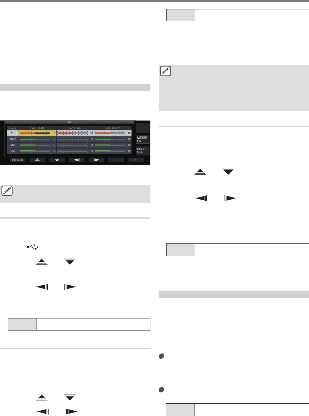
VOX Configuration Screen
1Press [VOX] to set the VOX function to ON.
2Press and hold [VOX] to display the VOX
configuration screen.
.
On the VOX configuration screen, the horizontal rows
represent the audio source input while the vertical columns
represent the setting item.
The VOX configuration screen ends when the transmitting
end is configured to a mode (non-audio mode) other than
SSB, AM and FM mode.
Adjusting VOX Gain
VOX gain of the VOX function allows the VOX gain level to be
adjusted according to the loudness of the audio input from the MIC
connector or the noise in the surroundings.
VOX gain of the input data from the ANI terminal of the ACC 2
connector, (USB-A or USB-B) or LAN connector on the rear
panel of this transceiver can be adjusted in the Data VOX mode.
1Press F2 [ ]/ F3 [ ] to select the audio source
input (horizontal row).
Select the audio source input row to adjust from “MIC”, “ACC
2”, “USB” and “LAN”.
2Press F4 [ ]/ F5 [ ] to select the “VOX GAIN”.
3Press F6 [–]/ F7 [+] or turn the [MULTI/CH] control
to adjust the VOX level.
Input signal from the audio source selected in step 2, and adjust
the level to activate transmission when audio signals are input.
Setting
Value 0 to 10 (default) to 20 (1 step)
Adjusting the Anti VOX Gain Level
When the VOX function is ON, transmission may be activated by
the playback sound from the speaker in some cases in addition to
audio from the microphone. Speaker sound may be transmitted if
the speaker volume is configured to a high level. This function can
be used to prevent unintended transmission by configuring the anti
VOX level to adjust the lower limit for activating the VOX function
with respect to the playback sound from the speaker.
1Press F2 [ ]/ F3 [ ] to select the audio source
input.
2Press F4 [ ]/ F5 [ ] to select “ANTI VOX”.
3Press F6 [–]/ F7 [+] or turn the [MULTI/CH] control
to adjust the sensitivity of the anti VOX gain.
Adjust the sensitivity of the anti VOX level so that transmission
will not be activated by the playback sound from the speaker.
Setting
Value 0 to 20 (1 step)
•The smaller the anti VOX gain value, the more susceptible
the transceiver is to playback sound from the speaker.
•The default settings are as follows.
•Microphone: 10
•ACC 2: 0
•USB: 0
•LAN: 0
●When a headphone is connected to the PHONES
connector, the VOX function (transmission) will not be
activated by the speaker audio regardless of the audio
source and anti VOX level settings.
●Anti VOX gain applies to audio sources other than Data
VOX.
●The speaker output level is compared with the ANTI VOX
level for any input line.
Adjusting VOX Delay Time
During transmission of audio or data using the VOX function, the
transceiver may sometimes be restored to the receiving state, and
the end of the audio that is clipped off may not be transmitted as
a result. To prevent this from occurring, the delay time can be
adjusted to insert an appropriate pause before switching from the
transmitting to the receiving state.
1Press F2 [ ]/ F3 [ ] to select the audio source
input (horizontal row).
Select the audio source input row to adjust from “MIC”, “ACC
2”, “USB” and “LAN”.
2Press F4 [ ]/ F5 [ ] to select the “VOX
DELAY”.
3Press F6 [–]/ F7 [+] or turn the [MULTI/CH] control
to select the delay time.
Input signal from the audio source selected in step 2, and adjust
the delay time before returning to the receiving state after audio
input has ended.
Setting
Value 0 to 10 (default) to 20 (1 step)
•When “MIC” is selected, adjust the delay time while
speaking into the microphone.
•The delay time for “MIC” can also be adjusted by turning the
[DELAY] control.
VOX Voice Delay
When the VOX function is ON, there may be a time lag before
transmission begins after voice input has started. For this reason,
the beginning part of the audio may be clipped off. To prevent this
phenomenon from occurring wherever possible, a VOX voice
delay time can be configured between the timing when
transmission is activated and before audio signals are sent out.
When using a microphone as the audio source input
for transmission:
Configure in Menu [6-13] “VOX Voice Delay
(Microphone)”
When using devices other than a microphone as the
audio source input for transmission:
Configure in Menu [6-14] “VOX Voice Delay (Except
Microphone)”
Setting
Value Off/ Short/ Middle (default)/ Long
8 TRANSMIT FUNCTIONS
8-2
TX Monitor
TX audio can be monitored while transmission is in progress. This
is a convenient tool for checking the effect of the speech processor
or TX equalizer. In the FSK and PSK modes, FSK and PSK signals
transmitted by this transceiver can be monitored.
Press [MONI] to turn the TX monitor ON or OFF
The [MONI] LED lights up in green when the TX monitor is
turned on.
•The ON/OFF status of the TX monitor and monitor level are
stored in the memory for each of the mode groups below.
During split operation, the mode at the transmitting end will
be monitored.
•SSB/ FM/ AM
•SSB-DATA/ FM-DATA/ AM-DATA
•FSK/ PSK
•Each time there is a change in the mode, the transceiver
switches back to the TX monitor ON/OFF status stored in
each group. TX monitor is always OFF in the CW mode.
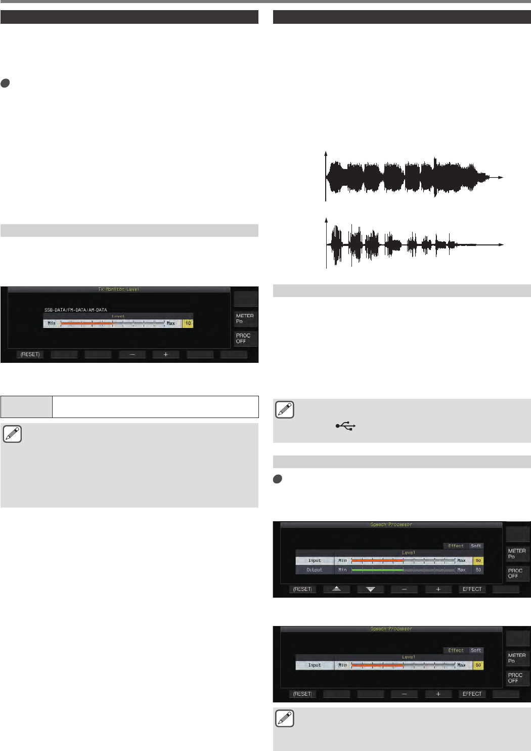
Adjusting the TX Monitor Level
The volume level when monitoring the TX audio can be adjusted.
1Press and hold [MONI] to display the TX Monitor
Level configuration screen.
.
2Press F4 [–]/ F5 [+] or turn the [MULTI/CH] control
to select the TX monitor level.
Setting
Value 0 to 10 (default) to 20 (1 step)
●Feedback may occur when a speaker is used in the SSB,
AM or FM mode. Make use of a headphone instead.
●Transmission of CW messages cannot be monitored
using the TX monitor. To monitor CW messages, make
use of CW sidetone.
●In the FM, FSK and PSK modes, the audio of the TX
monitor may differ from the audio of the signal that is
actually transmitted.
Speech Processor
In the SSB mode, TX output power varies according to the
loudness of the audio from the transmitting transceiver, which may
sometimes cause audibility to deteriorate at the receiving
transceiver. A speech processor can be used in this case to
compress signals via digital signal processing to raise the average
power.
Similarly, using the speed processor in the AM or FM mode
stabilizes the degree of modulation regardless of the loudness of
the audio from the transmitting transceiver and helps to enhance
intelligibility.
.
Time
Speech
Processor
OFF
Amplitude Level
Time
Speech
Processor ON
Amplitude Level
Turning ON/OFF Speech Processor
1Press the mode key to select either SSB, AM or FM
mode.
2Press F [PROC].
Pressing F [PROC] each time toggles the speech processor
between ON and OFF.
•When the speech processor is set to ON, “PROC
OUT:nnn” is displayed at the top of the screen. [nnn: 0 to
100]
●The speech processor also functions with respect to
audio input from the ANI terminal of the ACC 2 connector
or the (USB-B) connector on the rear panel of this
transceiver.
Speech Processor Configuration Screen
Press and hold F [PROC] to display the Speech
Processor configuration screen
SSB/SSB-DATA/AM/AM-DATA Mode
.
FM/FM-DATA Mode
.
●Switching the mode at the transmitting end to a non-
audio mode while the Speech Processor configuration
screen is displayed ends the Speech Processor
configuration screen.
TRANSMIT FUNCTIONS 8
8-3
Configuring the Speech Processor Input Level
1Press F2 [ ]/ F3 [ ] to select “Input”.
2Press F4 [–]/ F5 [+] or turn the [MULTI/CH] control
to adjust the input level.
Setting
Value 0 to 50 (default) to 100 (1 step)
●The speech processor input level is used to adjust the
input level of the mixed audio between the audio source
input configured for microphone gain and that configured
on the audio source input screen.
Configuring the Speech Processor Output Level
1Press F2 [ ]/ F3 [ ] to select “Output”.
•“Output” is not displayed when the transmitting transceiver
is in the FM mode.
2Press F4 [–]/ F5 [+] or turn the [MULTI/CH] control
to adjust the output level.
•The output level can also be adjusted by turning the [MIC/
PITCH)] control.
Setting
Value 0 to 50 (default) to 100 (1 step)
●Configuring the output to a level that is too high causes
distortion to occur in the TX signals and deterioration in
the radio wave quality as a result.
●The speech processor output level is applied to both the
audio input from the microphone as well as the audio
source configured on the audio source input screen.
●The speech processor output level is fixed and not
changeable in the FM mode.
Configuring the Speech Processor Effect
It is possible to configure how TX signals are to be processed by
the speech processor.
Press F6 [EFECT].
Pressing F6 [EFECT] each time switches the effect type.
Setting
Value Soft (default)/ Hard
Hard: Places priority on raising the average power although
signals may remain distorted.
Soft: Places priority on reducing the level of distortion with minimal
effect on raising the average power.
●The speech processor effect selected is the same in
each mode.
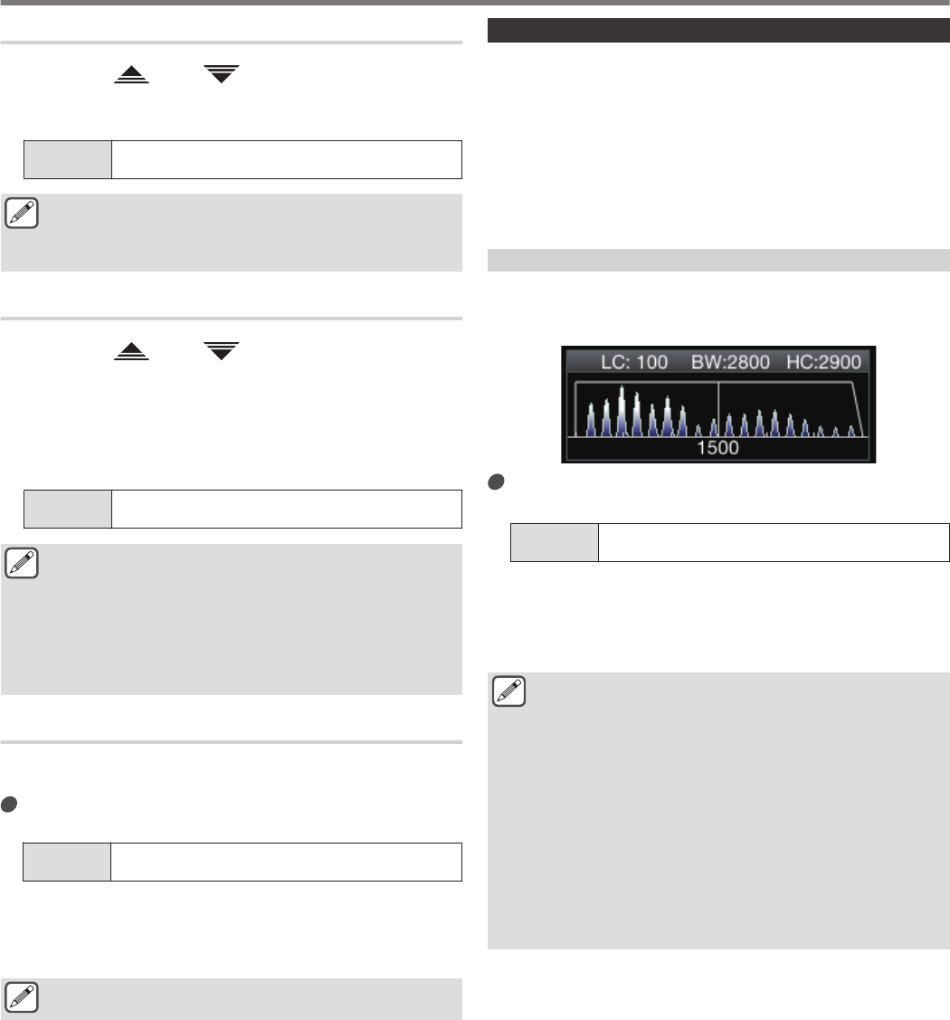
TX Filter
Configure the bandwidth of the SSB/AM or SSB-DATA/AM-DATA
TX filter to a low cutoff frequency or a high cutoff frequency.
•The filter display area switches automatically according to
transmission in the SSB, SSB-DATA, AM and AM-DATA
modes.
•A trapezoidal waveform of the low cutoff/high cutoff frequency
configured with this function is displayed with the settings at the
top (LC: low cutoff frequency; BW: occupied bandwidth; HC:
high cutoff frequency).
Displaying the Filter Scope during Transmission
During transmission, an image of the passband width for the TX
filter and the audio FFT of the TX audio can be displayed on the
filter scope.
.
Configure in Menu [8-01] “TX Audio Waveform
Display”
Setting
Value Off/ On (default)
On: Displays the TX filter bandwidth as well as TX monitor
waveform on the filter scope during transmission in the SSB,
FM and AM modes.
Off: The filter scope area maintains the last display during
transmission and the waveform is not displayed.
●During transmission in the CW, PSK and FSK modes,
the image of the filter passband characteristics during
reception is maintained. In modes other than those
above, an image of the filter passband characteristics is
displayed based on the HI/LO cut setting of the TX filter.
In the FM (including DATA) mode, an image of the
passband characteristics for the fixed filter is displayed.
●When the Audio Scope screen is displayed, waveform
is not displayed in the filter scope.
●The setting for this function cannot be switched while
transmission is in progress.
●When HI/SHIFT or LO/WIDTH is operated during
transmission while the TX audio waveform display is ON,
the setting value of the RX filter changes and the RX filter
display appears temporarily.
8 TRANSMIT FUNCTIONS
8-4
Changing the TX Filter Bandwidth
●Please make use of the TX filter while ensuring that the
occupied bandwidth in the SSB mode falls within the
permitted range as stipulated by the relevant laws.
Configuring the Low Cutoff Frequency in the SSB/AM
Mode
Configure in Menu [6-06] “TX Filter Low Cut
(SSB/AM)”
Setting
Value 10/ 100 (default)/ 200/ 300/ 400/ 500 [Hz]
Configuring the High Cutoff Frequency in the
SSB/AM Mode
Configure in Menu [6-07] “TX Filter High Cut
(SSB/AM)”
Setting
Value 2500/ 2600/ 2700/ 2800/ 2900 (default)/ 3000/ 3500/
4000 [Hz]
Configuring the Low Cutoff Frequency in the SSB-
DATA/AM-DATA Mode
Configure in Menu [6-08] “TX Filter Low Cut (SSB-
DATA/AM-DATA)”
Setting
Value 10/ 100 (default)/ 200/ 300/ 400/ 500 [Hz]
Configuring the High Cutoff Frequency in the SSB-
DATA/AM-DATA Mode
Configure in Menu [6-09] “TX Filter High Cut (SSB-
DATA/AM-DATA)”
Setting
Value 2500/ 2600/ 2700/ 2800/ 2900 (default)/ 3000/ 3500/
4000 [Hz]
TX Equalizer
This item can be used to alter the frequency characteristics of the
TX audio via DSP sound processing. It enables correction of the
microphone frequency characteristics as well as transmission in
the audio quality according to the audio properties or user’s
preferences.
Turning ON/OFF TX Equalizer
1Press the mode key to select either SSB, AM or FM
mode.
2Press F [TX EQ].
Pressing F [TX EQ] each time toggles the TX equalizer
between ON and OFF.
●The TX equalizer turns OFF automatically when this
transceiver is configured to a mode other than SSB, AM
or FM.
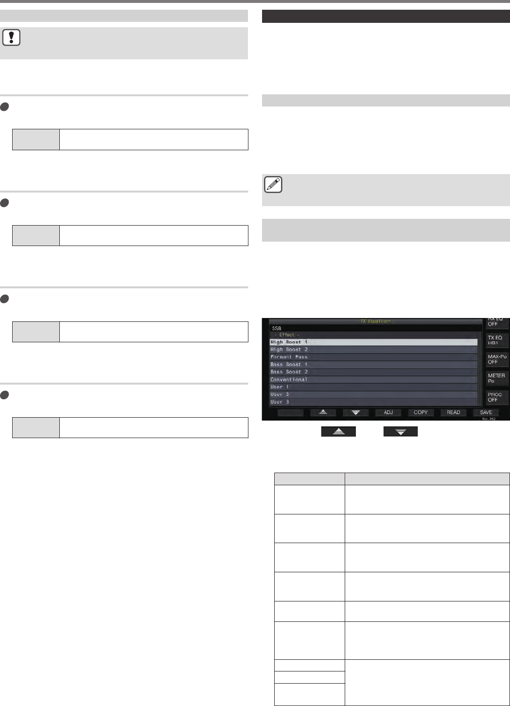
Selecting a Frequency Characteristic for the TX
Equalizer
This transceiver comes with 6 types of frequency characteristics
for the TX equalizer. In addition, there are 3 other types that can
be customized according to the user’s preferences. A selection
can be made from these options.
1Press and hold F [TX EQ] to display the TX Equalizer
screen.
.
2Press F2 [ ]/ F3 [ ] or turn the [MULTI/
CH] control to select a characteristic.
•Make a selection based on the equalizer effects in the table
below.
Effects Purpose
High Boost 1 (HB1) Boosts the high frequency component. This is
effective for audio sound that contains a low
frequency component.
High Boost 2 (HB2) Boosts the high frequency component. The low
frequency attenuation level for this option is half
of that of the HB1 option.
Formant Pass (FP) This option attenuates frequency components
that is outside the audio bandwidth so that the
audio can be heard more clearly.
Bass Boost 1 (BB1) Boosts the low frequency component. This is
effective for audio sound that contains a high
frequency component.
Bass Boost 2 (BB2) Boosts the low frequency component. The low
frequency is further boosted compared to BB1.
Conventional (C)
Applies a 3 dB boost to the frequency range of
600 Hz or higher. This is suited for
communication that attenuates gradually as it
approaches the low frequency range.
User 1 (U1) Frequency characteristics can be adjusted
according to the user’ preferences and stored in
the options between User 1 and User 3. The flat
frequency characteristic is selected in the
default setting.
User 2 (U2)
User 3 (U3)
TRANSMIT FUNCTIONS 8
8-5
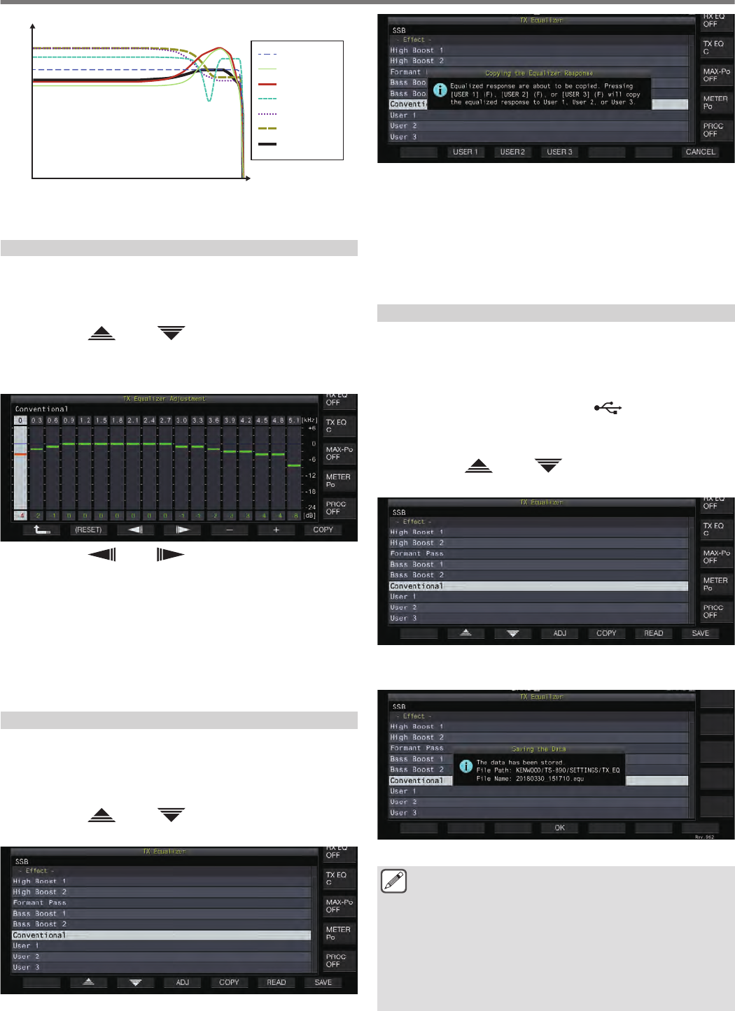
.
TX Characteristic Curve
Frequency (Hz)
OFF
HB1
HB2
FP
BB1
BB2
C
0
5
-5
-10
-30
-25
-20
-15
10
100103
102
101
Adjusting the TX Equalizer
The frequency characteristics of the TX equalizer can be adjusted
to produce the desired sound quality.
1Press and hold F [TX EQ] to display the TX Equalizer
screen.
2Press F2 [ ]/ F3 [ ] or turn the [MULTI/CH]
control to select a characteristic.
3Press F3 [ADJ] to display the TX Equalizer
Adjustment screen.
.
4Press F3 [ ]/ F4 [ ] to select the frequency
band to adjust.
5Press F5 [–]/ F6 [+] or turn the [MULTI/CH] control
to adjust the level of each frequency band.
•Touching a point on the RX Equalizer Adjustment screen
selects the corresponding band and changes the frequency
to the selected level.
An alternative way is to touch a rough point followed by fine-
tuning in steps 3 and 4.
•Pressing and holding F2 [(RESET)] resets all the frequency
levels to the default setting.
Copying the TX Equalizer Settings
Equalizer effects that are configured according to the user’s
preferences can be copied and saved as user-defined settings.
1Press and hold F [TX EQ] to display the TX Equalizer
screen.
2Press F2 [ ]/ F3 [ ] or turn the [MULTI/CH]
control to select a characteristic.
.
3Press F5 [COPY].
A message with instructions on how to specify the destination
for saving the settings is displayed.
.
•To copy after adjusting the TX equalizer settings, press F5
[COPY] on the TX Equalizer Adjustment screen.
4Press F2 [USER1], F3 [USER2] or F4 [USER3] to
specify the destination for saving the settings.
•Copying of the TX equalizer settings is complete and the
display returns to the TX Equalizer screen.
•Pressing F7 [CANCEL] returns the display to the TX
Equalizer screen without copying the settings.
Saving the TX Equalizer Settings
The steps to write the TX equalizer settings data are as follows.
•Before doing so, configure the destination for saving the data in
“File Storage Location” of the “USB/File Management Menu” to
“Internal Memory” or “USB Flash Drive”.
•To save the data to a USB flash drive, insert a USB flash drive
formatted using this transceiver into (USB-A).
1Press and hold F [TX EQ] to display the TX Equalizer
screen.
2Press F2 [ ]/ F3 [ ] or turn the [MULTI/CH]
control to select a characteristic.
.
3Press F7 [SAVE].
A message indicating that saving is complete is displayed.
.
4Press F4 [OK] to end the process.
●The saved file is named in the “yyyymmdd_hhmmss”
format. The extension of the saved file is “.equ”.
(Example) If the date is 10:20:30 a.m., February 15, 2018:
20180215_102030.equ
●The name of the destination folder is as follows. (The name
varies depending on the destination for saving files.)
USB flash drive: “KENWOOD\TS-890\SETTINGS\RX_EQ”
Built-in memory: “SETTINGS\RX_EQ”
●When removing the USB flash drive, make sure to execute
“Safe Removal of USB Flash Drive”. (See 11-6)
8 TRANSMIT FUNCTIONS
8-6
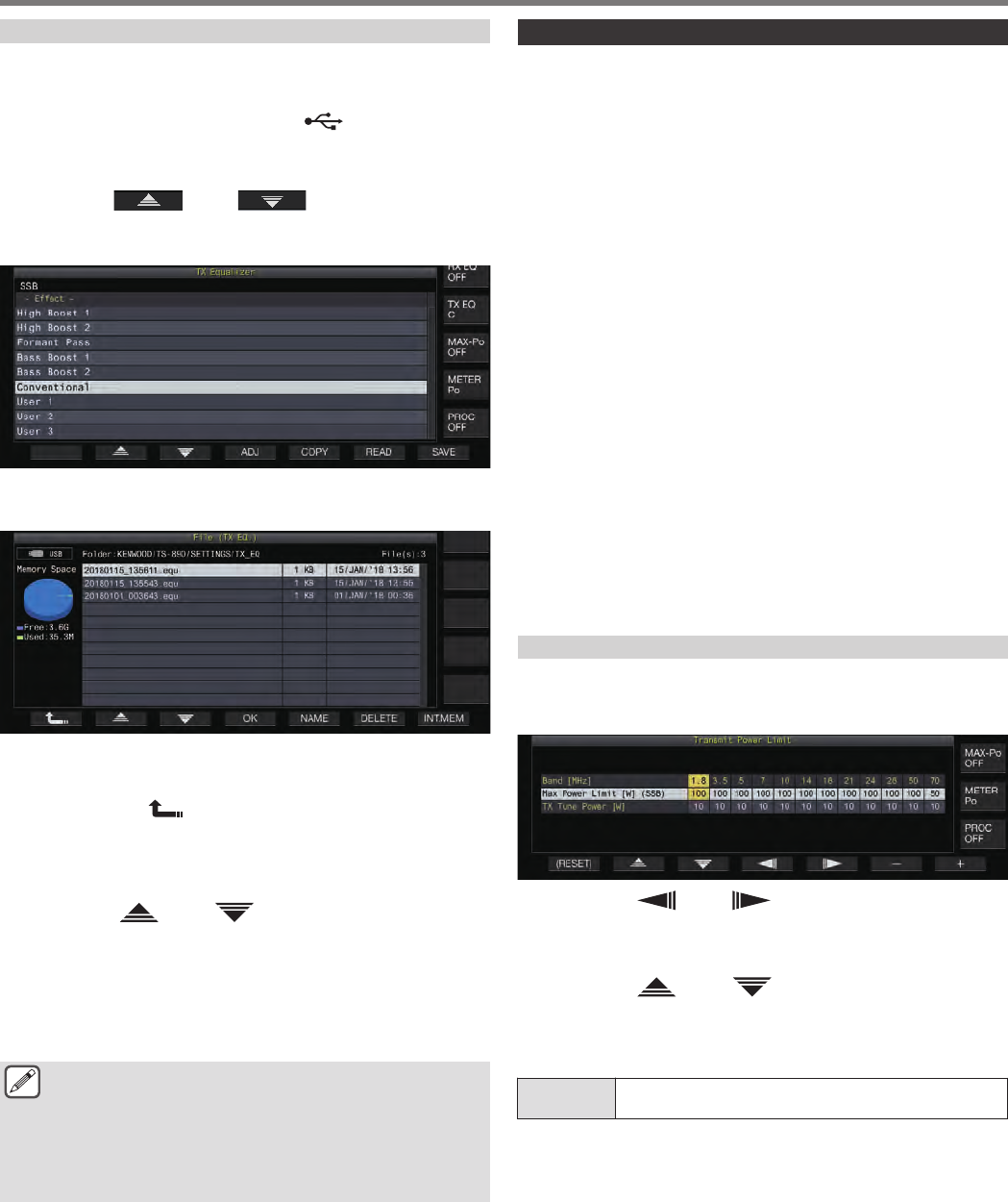
Reading the TX Equalizer Settings
The steps to read the TX equalizer settings that are saved in the
internal memory or USB flash drive are as follows.
•To read data from a USB flash drive, insert the USB flash drive
containing the TX equalizer data into (USB-A).
1Press and hold F [TX EQ] to display the TX Equalizer
screen.
2Press F2[ ] / F3[ ] or turn the [MULTI/
CH] control to select an equalizer characteristic to
read.
.
3Press F6 [READ] to display the File (TX EQ.) screen.
•The File (TX Equalizer) screen appears.
.
•To read data from the internal memory, press F7 [INT.MEM].
•To read data from the USB flash drive, press F7
[USB.MEM].
•Pressing F1 [ ] exits data file selection and returns the
display to the TX Equalizer screen.
•Pressing F6 [DELETE] displays a message to confirm
deletion of the file. Pressing F4 [OK] deletes the file.
•Pressing F5 [NAME] allows the file name to be changed.
4Press F2 [ ]/ F3 [ ] or turn the [MULTI/CH]
control to select a file.
5Press F4 [OK] to read the settings data.
•A “reading” message appears while reading is in progress,
which changes to a “reading complete” message when
reading is complete.
6Press F4 [OK].
●When removing the USB flash drive, make sure to follow
the proper steps on the USB screen to remove the device
safely. (See 11-6)
●Even if the equalizer type selected in step 3 is different
from the equalizer type that is associated with the file to
read, the settings data read will overwrite the TX
equalizer selected in step 3.
TX Tuning
This is a function that transmits constant output carrier
continuously regardless of the current TX mode. It is used for
purposes such as adjusting external antenna tuners or linear
amplifiers.
Assign TX tuning (“TX Tune 1” or “TX Tune 2”) to a PF key. For
more details, please refer to “PF (Programmable Functions)”.
Toggling between transmission and reception each
time the key is pressed:
1Press the PF key that is assigned with “TX Tune 1”.
•Transmits with a continuous carrier in the CW mode.
•“TX TUNE” blinks.
•The meter switches to SWR.
2Press the PF key that is assigned with “TX Tune 1”
again.
Stops transmission and returns to the original mode.
Activating transmission only while the key is pressed:
1Press the PF key that is assigned with “TX Tune 2”.
•Transmits in the CW mode while the key is pressed.
•“TX TUNE” blinks.
•The meter switches to SWR.
2Release the PF key that is assigned with “TX Tune
2”.
Stops transmission and returns to the original mode.
Adjusting TX Output Power during TX Tuning
1Press and hold F [MAX-Po] to display the Transmit
Power Limit screen.
.
2Press F4 [ ]/ F5 [ ] to select a frequency
band.
The settings of the selected frequency band column can be
changed.
3Press F2 [ ]/ F3 [ ] to select the “TX Tune
Power” (horizontal row).
4Press F6 [–]/ F7 [+] or turn the [MULTI/CH] control
to select a TX output power.
Setting
Value 5 to 10 (default) to 100 [W] (1-step)
TRANSMIT FUNCTIONS 8
8-7

Timeout Timer (TOT)
This function forcibly stops transmission and restores the receiving
status when the preconfigured TX time is exceeded.
Configure in Menu [6-02] “Time-out Timer”
Setting
Value Off (default)/ 3/ 5/ 10/ 20/ 30 [min]
ID Beep
During continuous transmission via the [SEND] key, [PTT] on the
microphone or the SS/PKS function on the rear panel, a beep tone
(ID ID “
・・ ‒・・ ・・ ‒・・
”) is output whenever the
preconfigured duration from the time transmission starts is
exceeded.
Configure in Menu [6-05] “ID Beep”
Setting
Value Off (default)/ 1 to 30 [min] (1 step)
●The transceiver may not function as intended in some
cases as it may return to the receiving state during CW
break-in or VOX transmission.
8 TRANSMIT FUNCTIONS
8-8
This transceiver comes with 120 memory channels, each of which
can be used for registering operating data.
The 120 memory channels are divided into 3 types which are
assigned respectively with the following channel numbers: 00 to
99, P0 to P9 and E0 to E9. Below is a general outline of the
respective memory channel types.
00 to 99 (standard memory channels):
For registering operating data that are frequently used.
P0 to P9 (memory channels for specific band
segments):
For registering programmable VFO or program scan frequency
ranges.
E0 to E9 (expanded memory channels):
These can be used in the same way as the standard memory
channels.
Data that can be registered in each of the memory channels are
as follows.
Operating Data
Channel
00 to 99/
E0 to E9 P0 to P9
RX Frequency
(Simplex)
TX Frequency
RX Mode
(Simplex)
TX Mode
Split Operation
Start Frequency
End Frequency
Tone/CTCSS/Cross Tone
Tone Frequency
CTCSS Frequency
Memory Name
Lockout
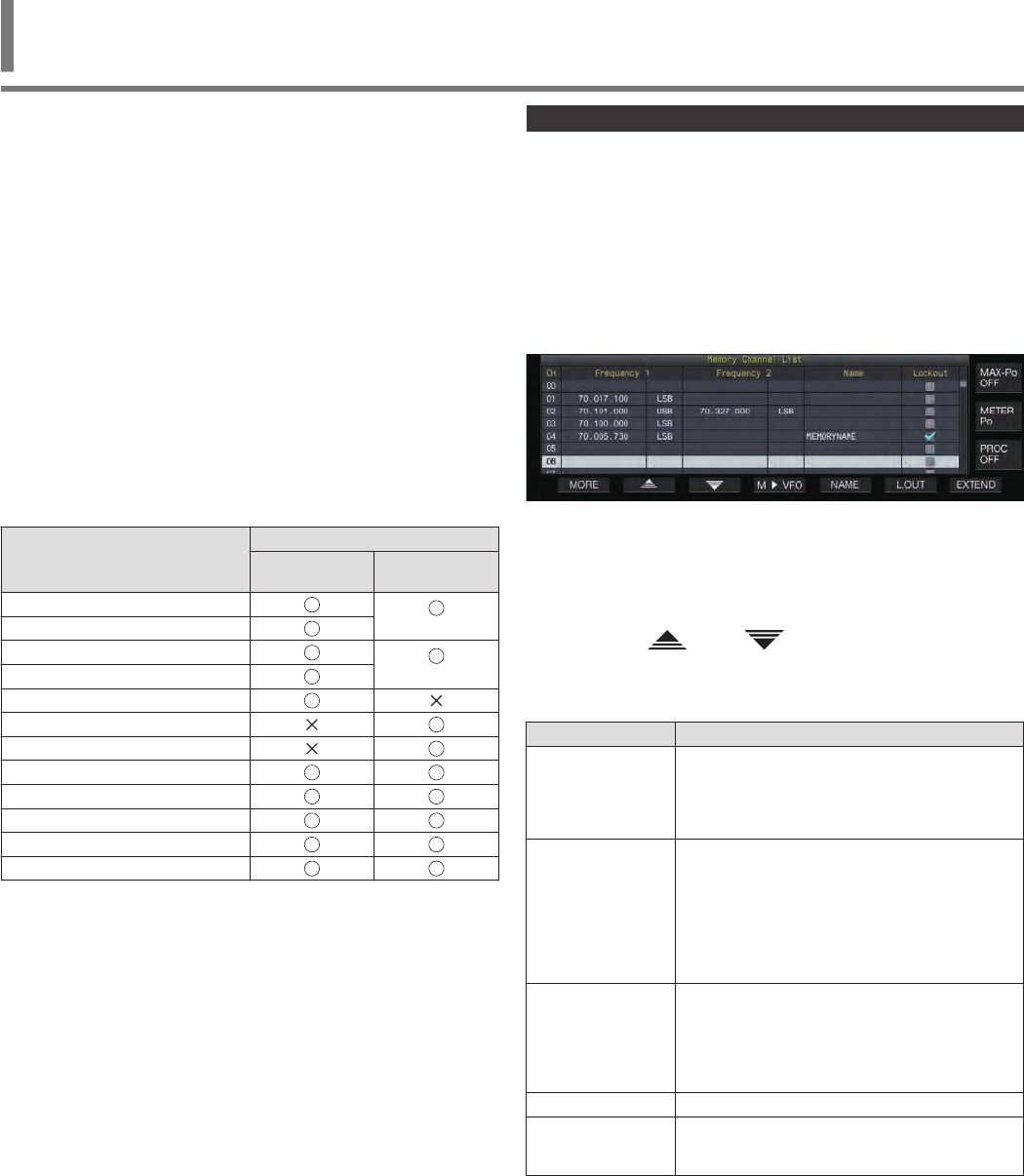
Displaying the Memory Channel List
Settings registered in a memory channel can be displayed on the
Memory Channel List screen. The channel for registering
operating frequency data or the channel to use can be selected on
the Memory Channel List screen.
Memory channels can be assigned with names on this screen.
A memory channel can be selected on the Memory Channel List
screen.
1Press F7 [M.LIST] to display the Memory Channel
List screen.
.
•The selected memory channel is indicated in white color.
When registering data to the memory channel, it changes
into a pink display.
•Pressing F7 [EXTEND] enlarges the Memory Channel List
screen display. Pressing it again restores the screen to the
original size.
2Press F2 [ ]/ F3 [ ] or turn the [MULTI/CH]
control to select a memory channel.
Operating frequency data that are displayed on the Memory
Channel List screen are as follows.
Operating Data Description
CH
Displays the channel number.
00 to 99: standard memory channels
P0 to P9: memory channels for specific band
segments
E0 to E9: expanded memory channels
Frequency 1
Registers a single frequency and mode for simplex
channels. (Simplex operation frequency or radio
station frequency)
Registers the RX frequency and mode during split
operation for split channels.
Registers the start frequency and mode of a band
segment for memory channels assigned to
specific band segments.
Frequency 2
This is left blank in the case of simplex channels.
Registers the TX frequency and mode during split
operation for split channels.
Registers the end frequency and mode of a band
segment for memory channels assigned to
specific band segments.
Name Displays the name of the memory channel.
Lockout Displays the lockout status of the respective
memory channels. Memory scan is not performed
for channels selected with a check mark.
MEMORY CHANNELS 9
9 MEMORY CHANNELS
9-1
Registering Operating Frequency Data to a Memory
Channel
The steps to register the frequency and mode to the memory
channel are as follows.
•To register a split channel, press [SPLIT] to switch to the split
mode and operate accordingly.
1Configure the frequency and mode to register.
2Press F7 [M.LIST] to display the Memory Channel
List screen.
3Press [M.IN].
4Press F2 [ ]/ F3 [ ] or turn the [MULTI/CH]
control to select the memory channel for
registering the operating data.
•Choose a memory channel from 00 to 99 or E0 to E9.
5Press [M.IN] or F4 [M.IN] to register the operating
data.
•Pressing F1 [CANCEL] or [ESC] exits the Memory Channel
List screen without registering the operating data to the
memory channel.
Configuring the Operating Data through Direct
Frequency Entry
The numeric keypad can be used to register a frequency to a
memory channel or make changes to an operating data that is
already registered to a memory channel.
This is handy for adjusting the frequency to a station with a fixed
frequency.
1Turn the [MULTI/CH] control to select the memory
channel (00 to 99 or E0 to E9) for registering the
operating data.
2Press [ENT] to enable use of the numeric keypad.
•The frequency entry mode starts up in the corresponding
band with all the frequency digits appearing as “-”.
•To change the operating mode, press the mode key.
.
3Key in a frequency value using the numeric keypad.
•“-” changes into a numeric value when a numeric key is pressed
and a value can be input starting from the highest-order digit.
•To enter 1.82 MHz, press [0/50], [1/1.8], [8/24] followed by
[2/3.5], and press [ENT] when input is complete.
•To enter a frequency lower than 6 MHz for K type
transceivers, start by keying in a “0”.
•To enter a frequency lower than 8 MHz for E type
transceivers, start by keying in a “0”.
•Pressing [CLR] clears the input and exits the frequency
entry mode.
4Press [ENT] to register the operating data.
The operating data is now registered to the memory channel
selected in step 2.
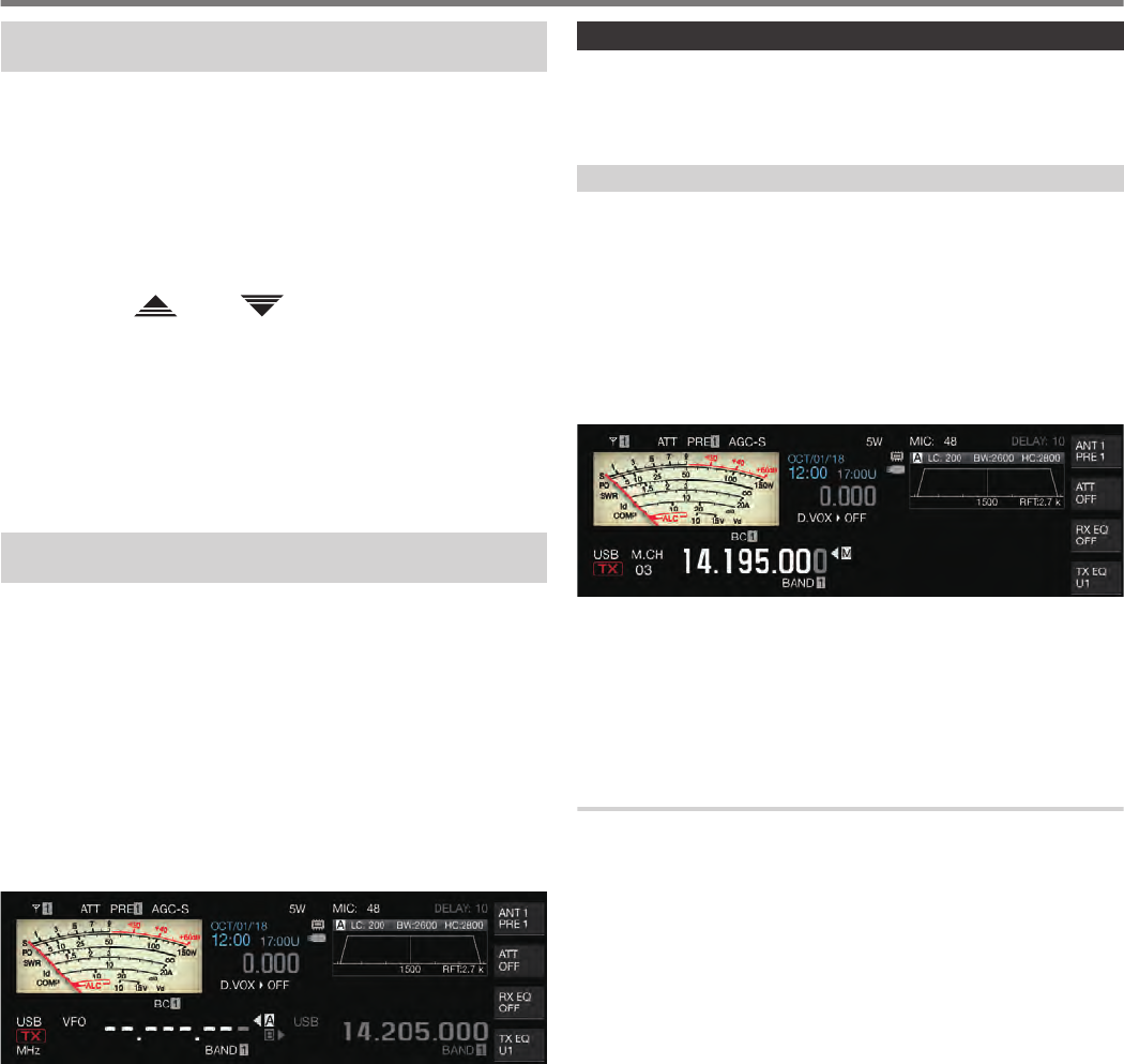
Memory Channel Mode
An operating data can be called up from a memory channel for
transmission or reception. Operating data such as the TX and RX
frequencies, mode and tone can be changed temporarily.
Operating in the Memory Channel Mode
Follow the steps below to call up the operating data of a memory
channel. Operating data that is registered in the memory channel
selected on the memory channel list is called up.
1Pressing [M/V] in the VFO mode to switch to the
memory channel mode.
The selected band switches to the operating data that is
registered in the memory channel on the memory channel list,
and the memory channel number that is used is displayed on
the screen.
.
2Press [UP] or [DOWN] on the microphone or turn the
[MULTI/CH] control to switch to the target memory
channel.
3Pressing [M/V] again exits the memory channel
mode.
The transceiver returns to the VFO mode.
Direct Entry of a Memory Channel Number
A memory channel number can be selected by pressing the
corresponding number on the numeric keypad.
1Enter the tens digit of the memory channel using the
numeric keypad.
•The tens digit of the channel number is being entered for the
selected band while the ones digit appears as “-”.
2Enter the ones digit of the memory channel using
the numeric keypad.
•The operating data corresponding to the entered number is
called up and the channel number entry mode ends.
•Pressing [CLR] clears the input and exits the channel
number entry mode.
9 MEMORY CHANNELS
9-2
Changing the Memory Channel Temporarily
During operation in the memory channel mode, it is possible to
change the frequency and mode temporarily without affecting the
registered memory channel settings.
Changing the Frequency Temporarily
Follow the steps below to change the frequency temporarily.
1Configure Menu [4-01] “Temporary Change
(Memory Channel Configurations)” to “On”.
Setting
Value Off (default)/ On
2Press [M/V] to switch to the memory channel mode.
3Turn the Tuning control to alter the frequency.
To register a frequency that has been changed, store it in a
different memory channel.
●For memory channels assigned to specific band
segments, changing the frequency or mode alters the
operating data that is registered in the corresponding
memory channel regardless of this setting.
●Operating data related to the operating mode and FM
tone can be altered temporarily regardless of this setting.
Copying the Operating Data of a Memory
Channel
Operating data of a memory channel can be copied to a VFO or
another memory channel.
Memory Shift (Memory → VFO)
The operating data of a memory channel can be copied to a VFO.
It comes in handy when the frequency to use is near the frequency
registered in a memory channel.
Selecting a Memory Channel and Copying to VFO
1Turn the [MULTI/CH] control in the memory channel
mode to select a memory channel.
2Press and hold [M/V], or press F6 [M VFO] to copy
the operating data to the VFO.
The operating data of the selected memory channel is copied
to the VFO.
•The transceiver exits the memory channel mode and enters
the VFO mode.
•When the operating data is temporarily changed, the altered
operating data is copied to the VFO.
•Operating data of memory channels assigned to specific
band segments cannot be copied to a VFO.
•Operating data that is registered in “Frequency 1” is copied
to the VFO.
•Performing memory shift of a split memory channel copies
the information of Frequency 1 to VFO A and that of
Frequency 2 to VFO B and switches the VFO mode to the
split state.
Copying Data from the Memory Channel List Screen
to VFO
1Press F7 [M.LIST] to display the Memory Channel
List screen.
2Press F2 [ ]/ F3 [ ] or turn the [MULTI/CH]
control to select a memory channel.
3Press and hold [M/V], or press F4 [M VFO] to copy
the operating data to the VFO.
•After operating data is copied to a VFO, the data at the
source will be erased.
•The transceiver exits the memory channel mode and enters
the VFO mode.
•Operating data of memory channels assigned to specific
band segments cannot be copied to a VFO.
•When in the VFO mode, operating data that is registered in
the memory channel selected on the Memory Channel List
screen is copied to the VFO.
Channel-to-Channel Copying
Operating data of a memory channel can also be copied to another
memory channel. This is useful in cases such as when sorting the
registered memory channels in a certain sequence.
1Press F7 [M.LIST] to display the Memory Channel
List screen.
2Press F2 [ ]/ F3 [ ] or turn the [MULTI/CH]
control to select the memory channel for which the
operating data is to be copied.
3Press F6 [COPY] to copy the operating data.
•The memory channel that is being copied changes into a
pink display.
4Press F2[ ]/ F3[ ] or turn the [MULTI/CH]
control to select the memory channel for
registering the copied operating data.
5Press F4 [M.IN] to end the process.
•Operating data of the memory channel selected in step 2 is
copied to the memory channel selected in step 4.
•Pressing F1 [CANCEL] or [ESC] ends the operation without
copying the operating data.
●Operating data of the standard memory channels (00 to
99) and expanded memory channels (E0 to E9) cannot
be copied to memory channels assigned to specific band
segments (P0 to P9). The same applies to copying from
memory channels for specific band segments to
standard and expanded memory channels.
●Operating data cannot be copied from memory channels
that are not registered with operating data.
MEMORY CHANNELS 9
9-3
Configuring the Program Scan Frequency
Range
The frequency range for programmable VFO or program scan can
be registered to the memory channels from P0 to P9. Register the
start frequency and end frequency in advance to enable changes
to the frequency or scanning operation within a specific range.
For more details on program scan, please refer to Chapter 10.
1When in the VFO mode, turn the Tuning or
[MULTI/CH] control to align the VFO frequency with
the frequency at which to start scanning.
2Press [M.IN] to display the Memory Channel List
screen.
3Press F2 [ ]/ F3 [ ] or turn the [MULTI/CH]
control to select the memory channel (P0 to P9) for
registering the frequency range.
4Press F4 [M.IN] or [M.IN] to register the start
frequency.
The start frequency is registered to “Frequency 1”.
5Turn the Tuning or [MULTI/CH] control to align the
VFO frequency with the end frequency.
6Press F4 [M.IN] or [M.IN] to register the end
frequency.
The end frequency is registered to “Frequency 2” and the
transceiver exits the Memory Channel List screen.
Erasing Memory Channels
Data from a registered memory channel can be erased.
1Press F7 [M.LIST] to display the Memory Channel
List screen.
2Press F2 [ ]/ F3 [ ] or turn the [MULTI/CH]
control to select a memory channel to be erased.
3Press and hold F4 [(CLEAR)] to erase the operating
data.
●When the operating data of a memory channel is erased
during operating in the memory channel mode, the
corresponding channel number will be maintained but
there will be no registered data inside.
●To erase all the memory channels, perform memory
channel reset.
Registering a Memory Channel Name
Each memory channel can also be assigned with a name. The
name should contain not more than 10 characters (alphanumeric
characters and symbols).
1Press F7 [M.LIST] to display the Memory Channel
List screen.
2Press F2 [ ]/ F3 [ ] or turn the [MULTI/CH]
control to select the memory channel to be named.
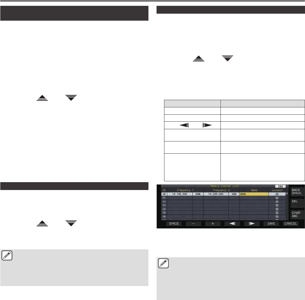
3Press F4 [NAME].
4Use the function keys, [MULTI/CH] control or USB
keyboard to enter a name.
•Enter a name that contains not more than 10 characters.
Key Behavior
F1 [SPACE] Inserts a space.
F2 [–]/ F3 [+] Selects a character.
F4 [ ]/ F5 [ ] Moves the cursor.
F [BACK SPACE] Deletes the character to the left of the
cursor.
F [DEL] Deletes the character to the right of the
cursor.
F [CHAR]
Switches the type of character to edit.
Pressing the key each time switches the
selection in the following sequence:
ABC (upper case) → abc (lower case)
→ !”# (symbols) → ABC (upper case)
.
5Press F6 [SAVE] to register the name.
•Pressing F7 [CANCEL] returns the display to the Memory
Channel List screen without assigning a name to the
memory channel.
●Characters that can be used are characters that can be
input using the keyboard selected in menu [9-01]
“Keyboard Language (USB Keyboard)”.
●Quick memory channels cannot be assigned with a
name.
●Only memory channels that contain registered operating
data can be assigned a name.
9 MEMORY CHANNELS
9-4
Quick Memory Channels
Quick memory is a function that enables speedy registration of
temporary data without specifying a memory channel. For
example, this function is useful for registering the operating data
of the mobile station that this transceiver communicates with when
moving within a specific band to search for a DX station.
A quick memory channel can be called up only during operation in
the VFO mode. The following types of operating data can be
registered to a quick memory channel.
•Frequency/mode of VFO A and VFO B
•TX and RX functions
•Status of the RIT function
•Status of the XIT function
•RIT/XIT frequency
•Status of the FINE-tuning function
•Status of the noise blanker
•Noise reduction status
•Status of the beat canceler
•Status of the notch filter function
•RX filter
Registering a Quick Memory Channel
Up to 10 quick memory channels (Q0 to Q9) can be registered on
this transceiver. The latest operating data that is registered is
assigned to “Q0”. Whenever operating data is newly registered,
the current registered data in “Q0” will be shifted to “Q1”, while the
newly-registered data will occupy the “Q0” channel.
Press [Q-M.IN] to register the operating data to the
quick memory channel.
•When in the VFO mode, pressing [Q-M.IN] registers the
operating data to the channel 0.
•When in the quick memory channel mode, pressing
[Q-M.IN] registers the operating data to the selected quick
memory channel.
•Each time new operating data is registered, the currently-
registered data will be shifted to the next larger channel
number.
●When the memory channel mode is active, pressing
[Q-M.IN] does not register data to a quick memory
channel.
●If all the quick memory channels are occupied with
registered data, pressing [Q-M.IN] erases the oldest
operating data which is stored in the largest quick
memory channel number.
Calling up a Quick Memory Channel
Follow the steps below to call up a registered quick memory
channel.
1Press [Q-MR] to call up the operating data from the
quick memory channel.
Displays the quick memory channel number.
2Turn the [MULTI/CH] control to switch the quick
memory channel.
•Pressing [Q-MR] again exits the quick memory channel
mode and returns the transceiver to the VFO mode.
●When data is retrieved from a memory channel for use
or when operating data is not registered to the quick
memory channel, pressing [Q-MR] does not call up the
quick memory channel.
●Temporary changes can be made to the frequency and
other operating data without affecting the operating data
that is registered in the quick memory channel. To
register the operating data after changes are made,
press [Q-M.IN] to register it to a quick memory.
Configuring the Number of Quick Memory Channels
This transceiver comes with 10 quick memory channels (Q0 to
Q9). However, it is possible to customize the number of quick
memory channels for registering data.
Configure in Menu [4-00] “Number of Quick Memory
Channels”
Setting
Value 3/ 5 (default)/ 10 [ch]
●When the number of quick memory channels is reduced
from a larger to a smaller number, registered data that
exceeds the smaller number of channels will be erased.
●The preconfigured number of quick memory channels
cannot be changed when a quick memory channel is
being called up.
Erasing a Quick Memory Channel
Follow the steps below to erase all registered operating data from
the quick memory channels.
1Press [Q-MR] to call up a quick memory channel.
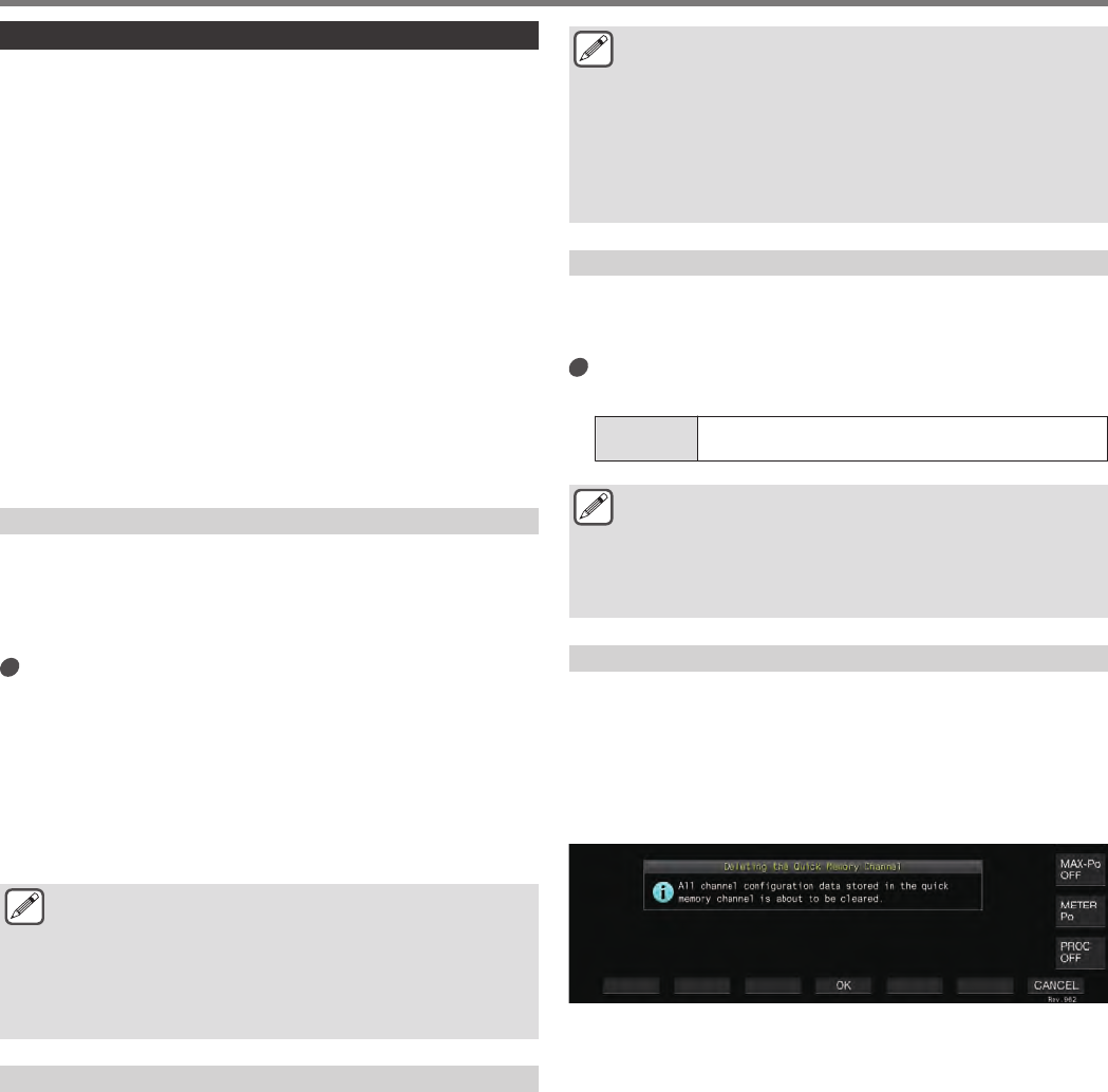
2Press and hold [Q-MR].
A message appears which prompts the user to confirm deletion
of all the operating data in the quick memory channels.
.
3Press F4 [OK] to erase the operating data.
•Operating data is erased from the quick memory channels
and the transceiver switches to the VFO mode.
•Pressing F7 [CANCEL] clears the confirmation message
without erasing the operating data from the quick memory
channels.
MEMORY CHANNELS 9
9-5

Memory Shift (Quick Memory → VFO)
Follow the steps below to copy the operating data of a quick
memory channel to the VFO.
1Press [Q-MR] to call up a quick memory channel.
2Turn the [MULTI/CH] control to select the quick
memory channel for which the operating data is to
be copied.
3Press and hold [M/V], or press F6 [M VFO].
•Operating data is copied from the quick memory channel to
the VFO and the transceiver switches to the VFO mode.
•When the operating data is temporarily changed, the altered
operating data is copied to the VFO.
9 MEMORY CHANNELS
9-6
Scan is a function that searches for signals by automatically
altering the frequency. This transceiver makes use of the following
scan methods to search for signals.
Scan Type Purpose
Normal Scan
Program Scan
Performs scan in the frequency
ranges that are registered in the
memory channels for specific band
segments (P0 to P9).
VFO Scan
Performs scan on the entire RX
frequency band. When Program
Scan is set to OFF for all the
memory channels for specific band
segments, Program Scan switches
automatically to VFO Scan.
However, when VFO Scan is
selected, VFO Scan is performed
even when not all channels are set
to OFF.
Scan Using
Memory
Channels
All-Channel
Scan Scans all Memory channels from 00
to 99, P0 to P9, and E0 to E9.
Group Scan Scans the grouped memory
channels.
Quick Memory
Scan Scans the Quick Memory channels.
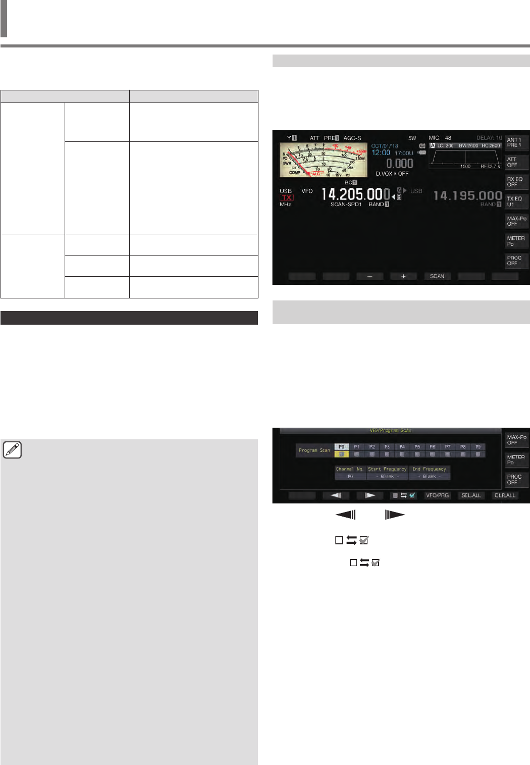
Program Scan
Program Scan performs scan between the range specified by the
start and end frequencies which are registered in the each of
memory channels for specific band segments (P0 to P9).
•Configure the frequency range for Program Scan in the memory
channels for specific band segments (P0 to P9). Up to 10
frequency ranges that are transmitted by specific stations can
be preconfigured. Enabling standby in a nearby frequency
makes it easy to perform tuning to a specific station when the
station starts communication in the preconfigured frequency
range.
●Program Scan performs scan between the start and end
frequencies of a memory channel for specific band
segments and moves to the next channel after scanning
of the specified frequency range has ended.
●While scanning is in progress, turning the Tuning or
[MULTI/CH] control allows the frequency to be changed
quickly. The same operation can also be used to change
the scanning direction.
●Scanning is performed in the ascending order from low
to high frequency. Configuring the end frequency to a
value smaller than the start frequency by turning the
Tuning or [MULTI/CH] control reverses the scanning
direction (high to low frequency).
●Scanning is performed based on the step frequency of
the Tuning control when in the SSB, CW, FSK and PSK
modes, while it is based on the step frequency of the
[MULTI/CH] control when in the FM mode, and fixed at
100 Hz in the AM mode.
●Scanning stops when signals are received while
performing Program Scan (VFO Scan) in the FM mode
or during Memory Scan (All-channel Scan or Group
Scan) or Quick Memory Scan regardless of the operating
mode. For more information on the conditions to resume
scanning, please refer to “Configuring the Conditions for
Resuming Scan”.
●During standby for the CTCSS tone in the FM mode,
scan stops only when there is a matching CTCSS tone.
●When the [SQL] control is turned to the right to a level
that far exceeds the squelch threshold while in the FM
mode, scanning may not stop even at a channel where
a signal is present. Configure the squelch level to a point
that is near the squelch threshold.
Starting the Program Scan (VFO Scan)
1Press [M/V] to switch to VFO mode.
2Press F5 [SCAN] to start program scan (VFO scan).
•Pressing F5 [SCAN] again or [ESC] ends the Program Scan
(VFO Scan).
.
Configuring the Program Scan (VFO Scan)
Frequency Range
Scanning can be configured to the frequency range specified in
the memory channels for specific band segments (Program Scan)
or the entire RX frequency band (VFO Scan).
To perform Program Scan, register the memory channels for
specific band segments.
1Press [M/V] to switch to VFO mode.
2Press and hold F5 [SCAN] to display the Program
Scan segment screen.
.
3Press F2 [ ]/ F3 [ ] to select a memory
channel for specific band segments.
4Press F4 [ ] to select whether to scan the
memory channel for specific band segments.
•Pressing F4 [ ] each time selects (performs scan) or
deselects (does not perform scan) the checkbox.
•When performing VFO Scan, deselect the checkboxes for
all the memory channels for specific band segments or press
[VFO/PRG] to switch the display to “VFO SCAN”.
•Pressing F6 [SEL.ALL] selects the checkboxes for all the
memory channels for specific band segments.
•Pressing F7 [CLR.ALL] deselects the checkboxes for all the
memory channels for specific band segments.
SCAN 10
10 SCAN
10-1
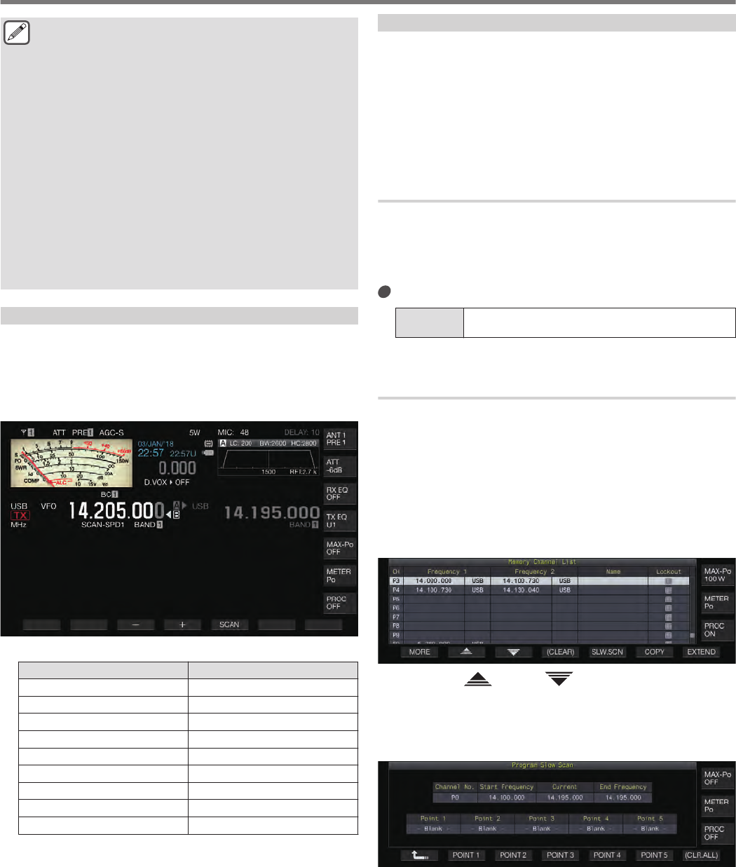
●Examples on the configuration of Program Scan and
VFO Scan:
•Configure the memory channels for specific band
segments such that the checkboxes for P1, P3 and
P5 are selected. Next, press F5 [SCAN]. Program
Scan starts and scanning is performed in the
frequency range registered for the respective
channels.
•Configure the memory channels for specific band
segments such that all the checkboxes are
deselected and press F [SCAN]. Or press [VFO/
PRG] to switch the display to “VFO SCAN”. VFO Scan
is performed on the entire RX frequency band.
•The checkbox will remain deselected for memory
channels that do not contain any operating data.
These checkboxes cannot be selected.
•For more details on registering memory channels for
specific band segments, please refer to 9-4
“Configuring the Program Scan Frequency Range”.
Switching the Scan Speed
The time interval for switching the Program Scan (VFO Scan)
frequency can be configured in modes other than FM.
1Press F3 [–] or F4 [+] while Program Scan (or VFO
Scan) is in progress.
The scan speed is shown below the frequency display.
.
The frequency switching interval changes as follows.
Scan Speed Display Frequency Switching Interval
SCAN-SPD1 10 ms
SCAN-SPD2 30 ms
SCAN-SPD3 100 ms
SCAN-SPD4 150 ms
SCAN-SPD5 200 ms
SCAN-SPD6 250 ms
SCAN-SPD7 300 ms
SCAN-SPD8 350 ms
SCAN-SPD9 400 ms
Program Slow Scan
Program Slow Scan is a function that extends the frequency
switching interval (performs scan more slowly) using the
preconfigured frequency for performing Program Scan (frequency
point) and the frequencies before and after this point (segment).
Switching slowly between the specified frequency (frequency
point) and the corresponding segment allows the communication
status to be checked in detail.
•To perform Program Slow Scan, register a frequency range to
a memory channel for specific band segments in advance.
Turning ON/OFF Program Slow Scan
To combine the use of Program Slow Scan while Program Scan is
running, set Program Slow Scan to ON in advance.
•When scanned frequency falls in the segment for Program Slow
Scan during Program Scan, “SCAN-SLOW” is displayed on the
screen and the speed of frequency switching slows down.
Configure in Menu [4-02] “Program Slow Scan”
Setting
Value Off/ On (default)
Configuring the Frequency Points for Program Slow
Scan
The frequency points for extending the frequency switching
interval during Program Slow Scan can be configured as follows.
•Up to 5 frequency points can be configured for each memory
channel assigned to specific band segments (P0 to P9).
•To configure the frequency points, register a band segment to
a memory channel for specific band segments in advance.
1Press [M/V] to switch to the memory channel mode.
2Press F7 [M.LIST] to display the Memory Channel
List screen.
.
3Press F2 [ ] or F3 [ ], or turn the [MULTI/CH]
control to select a memory channel for specific
band segments.
4Press F5 [SLW.SCN] to display the Program Slow
Scan screen.
.
5Turn the Tuning control and align the “Current”
frequency as the frequency point for Program Slow
Scan.
6Press any of the function keys (F2 [POINT 1] to F6
[POINT 5]) to configure the center point of the
preferred frequency range to perform Program
Slow Scan.
•Pressing and holding the key clears the frequency point that
is stored.
•Pressing and holding F7 [(CLR ALL)] clears all the
frequency points.
10 SCAN
10-2
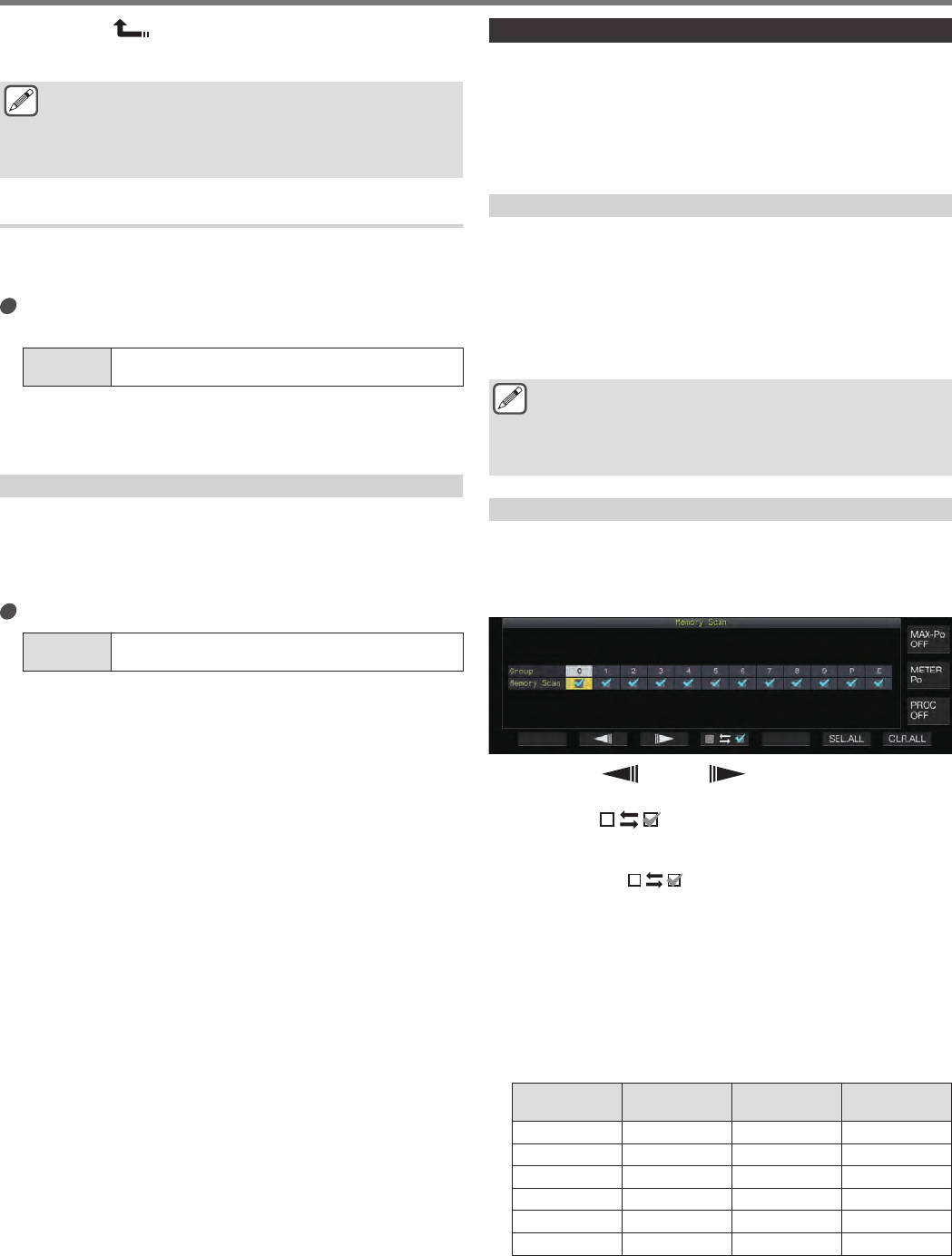
7Press F1 [ ] to exit the Program Slow Scan
screen.
The display returns to the Memory Channel List screen.
●Pressing a function key (F2 [Point 1] to F6 [POINT 5])
that already contains a frequency point overwrites the
frequency point with the new input.
●When configuring a frequency point, frequencies that are
smaller than 10 Hz are rounded off.
Configuring the Segment for Program Slow Scan
The frequency switching interval during Program Scan slows down
in the preconfigured segment that contains frequencies before and
after the frequency point for Program Slow Scan.
Configure in Menu [4-03] “Program Slow Scan
Range”
Setting
Value 100/ 200/ 300 (default)/ 400/ 500 [Hz]
•For example, when 500 [Hz] is selected, the frequency
switching interval is extended to a range of ± 500 Hz from
the frequency point.
Scan Hold
While Program Scan (VFO Scan) is performed in a mode other
than FM, changing the frequency by turning the Tuning or [MULTI/
CH] control pauses the scan operation for 5 seconds.
Signals can be received temporarily without stopping the scan
operation.
Configure in Menu [4-04] “Scan Hold”
Setting
Value Off (default)/ On
When Scan Hold is set to “On”, signals are received with
Program Scan paused for 5 seconds.
Memory Scan
Memory Scan allows the registered memory channel to be
automatically switched at a specific time interval for scanning.
There are 2 types of Memory Scan modes. All-channel Scan
performs scan on all the memory channels that are registered with
operating data, while Group Scan performs scan on a selected
group among the memory channels.
Performing Memory Scan
1Press [M/V] to switch to the memory channel mode.
2Press F5 [SCAN] to start memory scan.
•Turning the [MULTI/CH] control allows the scan channel to
jump rapidly to the next or previous channels.
•Pressing F5 [SCAN] again or pressing [ESC] ends Memory
Scan.
•The scan direction is fixed at the ascending order.
●The frequency switching interval during Memory Scan is
400 ms. However, when a CTCSS tone is received in the
FM mode, the frequency switching interval is extended
to 600 ms. During Memory Scan, “SCANNING” is
displayed instead of the scan speed.
Configuring All-channel Scan and Group Scan
1Press [M/V] to switch to the memory channel mode.
2Press and hold F5 [SCAN] to display the Memory
Scan group screen.
.
3Press F2 [ ] or F3 [ ] to select a memory
group.
4Press F4 [ ] or turn the [MULTI/CH] control to
select whether to start scanning of the memory
channels belonging to a memory group.
•Pressing F4 [ ] each time selects (performs scan) or
deselects (does not perform scan) the checkbox.
•When performing All-channel Scan, select the checkboxes
for all the memory groups.
•Pressing F6 [SEL.ALL] selects the checkboxes for all
memory groups.
•Pressing F7 [CLR.ALL] deselects the checkboxes for all
memory groups.
•Memory channels are classified into memory groups as
follows. The classification of the memory groups and
channels cannot be altered.
Group Memory
Channel Group Memory
Channel
0 00 to 09 6 60 to 69
1 10 to 19 7 70 to 79
2 20 to 29 8 80 to 99
3 30 to 39 9 90 to 99
4 40 to 49 P P0 to P9
5 50 to 59 E E0 to E9
SCAN 10
10-3
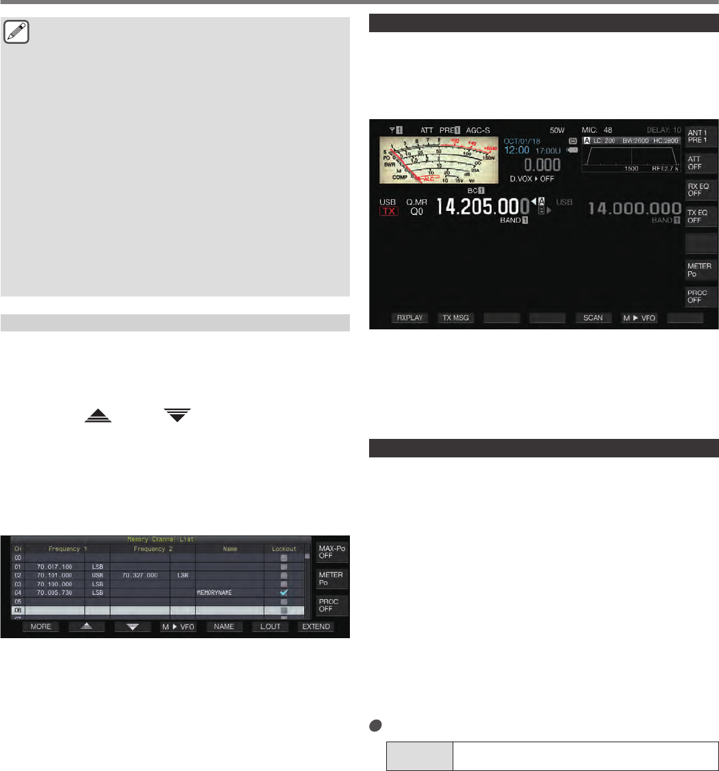
●Pressing F5 [SCAN] does not start the scan operation
when the memory groups to be scanned are configured
as follows.
•When the checkboxes for all the memory groups are
deselected.
•When operating data is not stored in the memory
channels of a memory group, even if the checkboxes
of the memory group are selected.
•When all the memory channels belonging to a
memory group are locked out, even if the checkboxes
of the memory group are selected.
●Examples on the configuration of All-channel Scan and
Group Scan:
•When the checkboxes for Memory Groups 1 and 5 are
selected, pressing F5 [SCAN] activates Group Scan.
In this case, scan is performed on the memory
channels included in Memory Groups 1 and 5.
•When the checkboxes for all memory groups are
selected, pressing F5 [SCAN] activates All-channel
Scan.
Memory Channel Lockout
Selected memory channels can be omitted (locked out) in advance
before performing Memory Scan.
1Press F7 [M.LIST] to display the Memory Channel
List.
2Press F2 [ ] or F3 [ ], or turn the [MULTI/CH]
control to select a memory channel.
3Press F6 [L.OUT] to lock out the memory channel.
•Lockout is applied to memory channels for which the
“Lockout” checkbox is selected.
•Pressing F6 [L.OUT] again cancels the lockout mode.
•“L.OUT” lights up in the standard mode screen and
compression mode screen.
.
Quick Memory Scan
Quick Memory Scan allows the registered quick memory channel
to be automatically switched at a specific time interval for
scanning.
1Press [Q-MR] to call up a quick memory channel.
.
2Press F5 [SCAN] to start quick memory scan.
•Turning the [MULTI/CH] control allows the scan channel to
jump rapidly to the next or previous channels.
•Pressing F5 [SCAN] again or pressing [ESC] ends Quick
Memory Scan.
•The scan direction is fixed at the ascending order.
Configuring the Conditions for Resuming Scan
Scanning stops when signals are received while performing
Program Scan (VFO Scan) in the FM mode or during Memory Scan
or Quick Memory Scan regardless of the operating mode.
•The conditions for resuming the scan operation after it has
stopped can be configured.
Time-operated (Time-operated mode):
Pauses scan for 3 seconds after signals are received. Continues
to pause scan for another 3 seconds if signal reception is still in
progress after 3 seconds.
Scan operation resumes after this interval even if reception is still
ongoing. (The maximum duration for pausing scan using the time-
operated mode is 6 seconds.)
Carrier-operated (Carrier-operated mode):
Pauses scan while signals are received. Scan operation resumes
when signals are not received for a duration of 2 seconds.
Configure in Menu [4-05] “Scan Resume”
Setting
Value Time-operated (default)/ Carrier-operated
10 SCAN
10-4
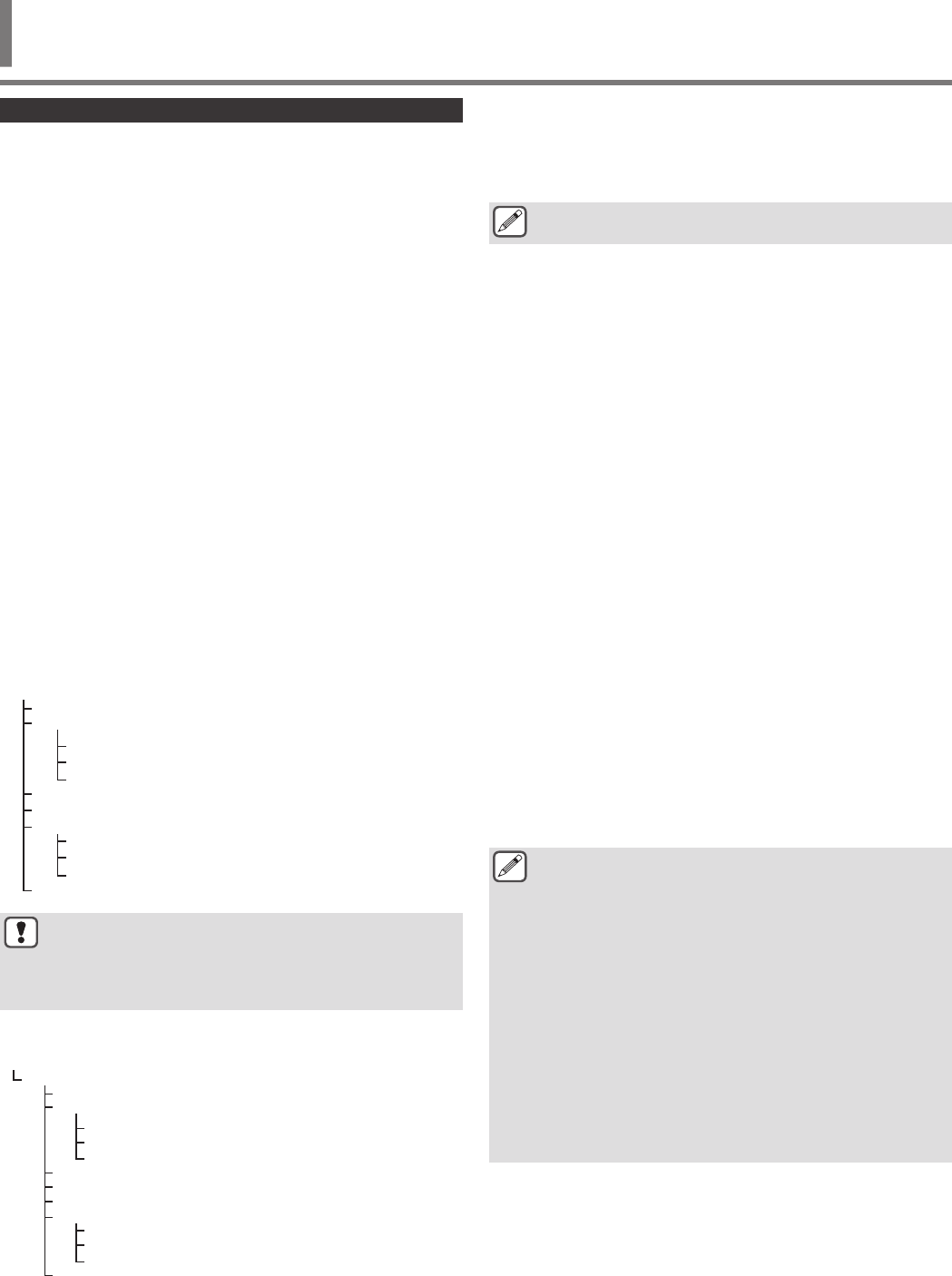
Managing Different File Types
The following data can be stored as files on this transceiver.
•Settings data of the transceiver
•Settings data of TX and RX equalizers
•Audio data of manual and full-time recordings
•Audio data of timer recordings
•Screen capture image data (can be stored but cannot be
displayed on this transceiver)
•CW, RTTY and PSK communication log data
•KNS communication log data (can be stored but cannot be
displayed on this transceiver)
Destination for Saving Files
Files are stored in the built-in memory of the transceiver (maximum
capacity of 1 GB) in the default setting. However, settings can be
changed for files to be saved to a USB flash drive that is connected
to the transceiver.
Copying Files Stored in the Built-in Memory to an
External Source
Files that are stored in the built-in memory of the transceiver can
be copied to a PC that is connected to this transceiver via a USB
cable.
Folder Configuration of the Built-in Memory
When copying files to a PC via a USB cable, the built-in memory
of the transceiver is recognized on the PC as a removable device
with the name “TS-890”. The folder configuration of the “TS-890”
removable device is as follows.
.
TS-890
CAPTURE
DECODE
KNS_LOG
RX_REC
SETTINGS
TIMER_REC
CW
FSK
PSK
DATA
RX_EQ
TX_EQ
Folder for audio files of timer recordings
Folder for TX equalizer data files
Folder for RX equalizer data files
Folder for settings data files
Folder for audio files of manual and full-time recordings
Folder for KNS communication log files
Folder for PSK communication log files
Folder for FSK communication log files
Folder for CW communication log files
Folder for captured image files
●All the folders above are read-only files. They cannot be
edited or deleted on the PC.
●Among the folders above, only those selected by the
operations in “Copying Files to a PC” (see 11-4) will
appear under “TS-890” removable device.
Folder Configuration of the USB Flash Drive
.
Folder for screen saver image files
Folder for audio files of timer recordings
Folder for TX equalizer data files
Folder for RX equalizer data files
Folder for settings data files
Folder for audio files of manual and full-time recordings
Folder for KNS communication log files
Folder for PSK communication log files
Folder for FSK communication log files
Folder for CW communication log files
Folder for captured image files
TS-890
CAPTURE
DECODE
KNS_LOG
IMAGE
RX_REC
SETTINGS
TIMER_REC
CW
FSK
PSK
DATA
RX_EQ
TX_EQ
KENWOOD
Image Files for Use as Screen Savers
Write image files to be used as screen savers (Type 3) in advance
to the “Folder for screen saver image files (IMAGE)” of the USB
flash drive such as via a PC before loading them into the built-in
memory of the transceiver.
●For more details on the method of configuration, please
refer to “Configuring the Screen Saver”. (16-1)
Saving Files (For Both USB Flash Drive and Built-in
Memory)
•When the date and time are not configured in the CLOCK menu,
the recorded date and time when the file is saved is determined
with the timing at which this transceiver is powered on as
January 1, 2018, 0:00.
•A maximum number of 255 files can be stored in each folder.
When trying to save files that exceed this number, an error
occurs and a screen showing “Insufficient Memory Size” is
displayed.
•If the USB flash drive is write-protected when writing files to the
USB flash drive, an error occurs and a screen showing
“Insufficient Memory Size” is displayed.
Compatible USB Flash Drives
•This transceiver does not come supplied with a USB flash drive.
Use a commercially available USB flash drive.
•The USB flash drive needs to be formatted by this transceiver
before it can be used. After formatting is complete, a folder is
automatically created in the USB flash drive. (Formatted to
FAT32)
•When formatting is performed, any file that exists on the USB
flash drive will be erased. To prevent data from being lost, back
up the necessary files to devices such as a PC before
formatting.
•When a compatible USB flash drive is connected to this
transceiver, any data that is not found in the folder configuration
will be automatically created.
•If multiple USB flash drives are connected to this transceiver at
the same time, only the first USB flash drive that is recognized
can be used.
●A USB flash drive and USB keyboard can also be
connected at the same time via a USB hub.
●The USB-A connector of this transceiver supports the
USB 1.1 standard. The USB flash drive is capable of
running at the Full Speed (maximum 12 Mbps) transfer
rate.
●We do not provide guarantee with regard to the operation
and power supply of all USB devices that are
commercially available.
●When using an extension cable, make use of one that
complies with the USB standard with a length not longer
than 3 m.
●If the power consumption of the connected device
exceeds the allowable current of this transceiver (0.5 A),
a “USB bus power error screen” is displayed.
●This transceiver does not support security-enabled USB
flash drives.
USB/FILE MANAGEMENT 11
11 USB/FILE MANAGEMENT
11-1
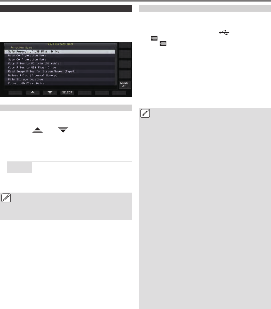
USB/File Management Menu Screen
1Press [MENU].
2Press F [USB/FILE] to display the USB/File
Management menu screen.
.
Configuring the Destination for Saving Files
Follow the steps below to select the destination for saving files
such as the transceiver data and audio recordings.
1Press F2 [ ]/ F3 [ ] to select “File Storage
Location”.
2Press F4 [SELECT].
3Press F4 [–]/ F5 [+] or turn the [MULTI/CH] control
to select the destination for saving the files.
Setting
Value Internal Memory (default)/ USB Flash Drive
Internal Memory: Saves files to the built-in memory of the
transceiver.
USB Flash Drive: Saves files to a USB flash drive.
●The destination for saving files cannot be changed while
manual recording or CW/RTTY/PSK communication log
recording is in progress. Pressing F4 [SELECT] in this
case displays a “File destination change error” on the
screen.
Saving Settings Data
Settings data or audio data created using this transceiver can also
be written to the built-in memory or a USB flash drive.
•To save the data to a USB flash drive, insert a USB flash drive
formatted using this transceiver into (USB-A).
•<< >> starts to blink when a USB flash drive is connected,
and << >> lights up when the USB flash drive is recognized
by this transceiver.
1Select “Save Configuration Data” in the USB/File
Management menu.
2Press F4 [SELECT].
File saving starts.
•While file saving is in progress, a “processing” screen is
displayed on the screen. (This is not displayed if the duration
of the saving process is very short.)
3When the “data saving complete screen” is
displayed, press F4 [OK].
●The settings data contains the data of all settings that are
currently configured on this transceiver. However, the
following are excluded.
•Data that are stored in the operating environment
(CONFIG A or B) that is not currently selected.
•Screen capture image files
•Audio data files of manual recordings, full-time
recordings and timer recordings
•Settings data files of TX and RX equalizers
•CW/TTY/PSK communication log files
•KNS communication log files
•Image files for screen savers (Type 3)
●The destination folder cannot be selected.
•USB flash drive: “\KENWOOD\TS-890\SETTINGS
\DATA”
•Built-in memory: “\SETTINGS\DATA”
●The extension of the saved file is “.dat”.
●The saved file is assigned with a name using the date
and time in the following format:
“yyyymmdd_hhmmss.dat”.
●(Example)
•20180215_102030.dat (File that is saved on February
15, 2018, 10:20:30 a.m.)
●To save files to a USB flash drive, check the following in
advance.
•The USB flash drive is formatted by this transceiver.
•The USB flash drive is correctly inserted into this
transceiver.
•There is sufficient free space on the USB flash drive.
•The USB flash drive is not write-protected or the file
system is not corrupted.
●If there is insufficient memory, “Insufficient Memory Size”
is displayed on the screen.
●If the USB flash drive is removed while files are being
saved to it, “Saving to USB flash drive unsuccessful” is
displayed on the screen.
●If the USB flash drive for saving files to is write-protected,
“Insufficient Memory Size” is displayed on the screen.
11 USB/FILE MANAGEMENT
11-2
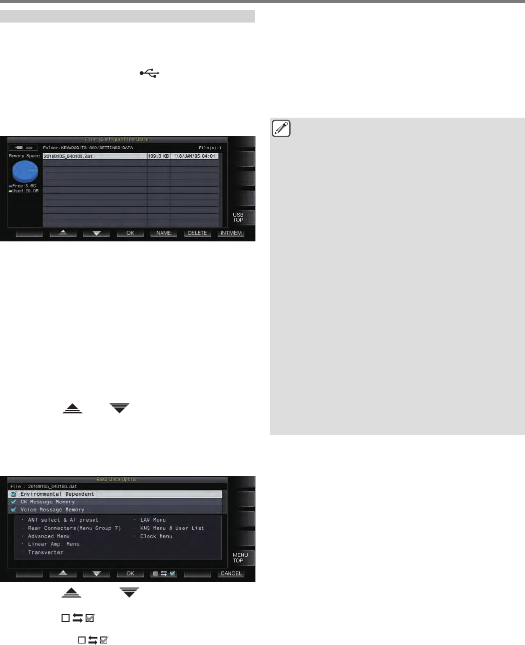
Reading Settings Data
Follow the steps below to read the settings data file of the
transceiver that is stored in the built-in memory or a USB flash
drive.
•To read data from a USB flash drive, insert the USB flash drive
containing the settings data into (USB-A).
1Select “Read Configuration Data” in the USB/File
Management menu.
2Press F4 [SELECT].
A screen for selecting the file (DATA) to read appears.
.
•Information of the location to read files from (built-in memory
or USB flash drive) that was last selected on this screen is
displayed. However, if a USB flash drive is not connected or
cannot be correctly recognized, information of the built-in
memory will be displayed.
•If no file is found, “No file is found.” is displayed on the
screen.
3Select the file to read.
•To read data from the internal memory, press F7 [INT.MEM].
•To read data from the USB flash drive, press F7
[USB.MEM]. (If a USB flash drive is not connected, a message
will appear prompting you to get ready the USB flash drive.)
•Pressing F5 [NAME] allows the file name to be changed.
•Pressing F6 [DELETE] displays a message to confirm
deletion of the file. Pressing F4 [OK] deletes the file.
4Press F2 [ ]/F3 [ ] or turn the [MULTI/CH]
control to select the settings data file to read.
5Press F4 [OK] to display the selection screen
(DATA) for reading the data.
•Pressing F7 [CANCEL] ends the operation without reading
a file.
.
6Press F2 [ ] or F3 [ ], or turn the [MULTI/CH]
control to select a function group to read.
7Press F5 [ ] to select the checkbox to the left
of the settings data name.
•Pressing F5 [ ] again deselects the checkbox.
(Settings data will not be read.)
8Repeat steps 7 and 8 to select the corresponding
checkboxes for the settings data to read.
9Press F4 [OK] to start reading the files.
Reading of settings data files with a check mark starts. When
reading starts, a reading in progress screen is displayed.
•Pressing F7 [CANCEL] exits the file selection screen
without starting reading and returns the display to the USB/
File Management menu screen.
•After the settings data files have been read successfully, a
message indicating that reading is complete is displayed.
10 Press F4 [OK] to end the process.
This transceiver reboots automatically.
●Data that are not created by this transceiver cannot be
read.
●The following function groups can be excluded from the
reading process.
•“Environmental Dependent” data (settings data that
are dependent on the installation environment)
•Antenna selection data and preset data of antenna
tuner
•Settings for items in menu group 6 (settings related
to the rear terminals)
•Advanced menu settings
•Linear amplifier menu settings
•Transverter settings
•LAN menu settings
•KNS menu settings and KNS registered users’ list
•Clock menu settings
•“CW/RTTY/PSK Message Memory” data (CW/RTTY/
PSK message memory)
•“Voice Message Memory” data (voice message data)
●If the settings data file is saved in a transceiver with a
newer firmware version, pressing F4 [OK] in step 9 will
result in an error. A “data reading error screen due to
mismatch between new and old firmware versions” is
displayed and reading is not executed.
●If the settings data file is corrupted, pressing F4 [OK] in
step 6 will result in an error. A “file reading NG screen” is
displayed and reading is not executed.
●If data mismatch is detected after reading a settings data
file, a “corrupted data is detected screen” is displayed.
When this occurs, pressing F4 [OK] runs a full reset and
reboots this transceiver.
USB/FILE MANAGEMENT 11
11-3
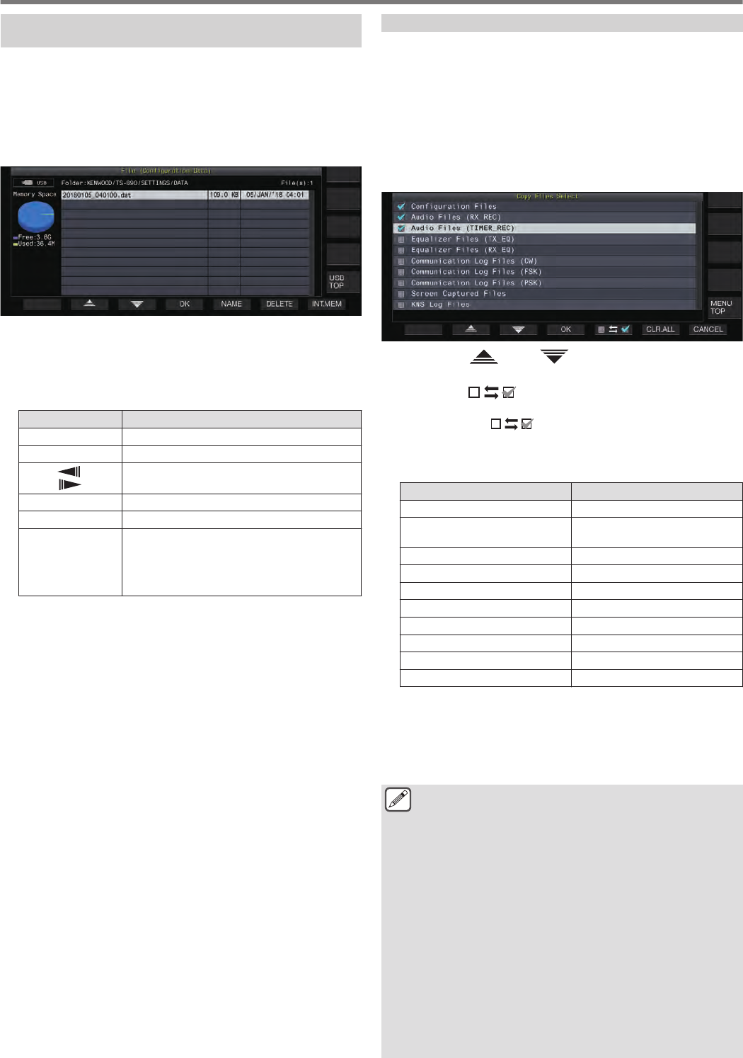
Changing the Name of Files Stored in the Built-in
Memory
The file name of the settings data that is stored on the transceiver
can be changed by the user to ease identification.
1Select “Read Configuration Data” in the USB/File
Management menu.
2Press F4 [SELECT] to display the screen for
selecting the file (DATA) to read.
.
3Press F5 [NAME].
The file name edit screen is displayed.
4Use the function keys and the [MULTI/CH] control
to edit the file name.
•Enter a name that contains not more than 255 characters.
Key Operation
F1 [SPACE] Inserts a space.
F2 [–]/ F3 [+] Selects a character.
F4 [ ]/ F5
[ ] Moves the cursor.
F [BACK SPACE] Deletes the character to the left of the cursor.
F [DEL] Deletes the character to the right of the cursor.
F [CHAR]
Switches the type of character to edit. Pressing
the key each time switches the selection in the
following sequence:
ABC (upper case) → abc (lower case) → !”#
(symbols) → ABC (upper case)
5Press F6 [SAVE] to save the file name.
•Pressing F7 [CANCEL] discards the edited information and
returns the display to the USB/File Management menu
screen.
Copying Files to a PC
Files that are stored in the built-in memory of this transceiver can
be copied to a PC.
•Connect the USB-B connector on the rear panel of this
transceiver to a PC using a commercially available USB cable.
(See 1-4)
1Select “Copy Files to PC (via USB Cable)” in the
USB/File Management menu.
2Press F4 [SELECT].
A screen for selecting the files to copy is displayed.
.
3Press F2 [ ]/ F3 [ ] or turn the [MULTI/CH]
control to select the items to copy.
4Press F5 [ ] to select the checkbox to the left
of the settings data name.
•Pressing F5 [] again deselects the checkbox. (Files
are not copied.)
•Pressing F6 [CLR.ALL] deselects all the checkboxes.
•Select at least 1 item to copy from the following.
Display Description
Configuration Files Settings data file
Audio Files (RX_REC) Audio files of manual and full-time
recordings
Audio Files (TIMER_REC) Audio files of timer recordings
Equalizer Files (TX_EQ)
TX equalizer data files
Equalizer Files (RX_EQ) RX equalizer data files
Communication Log Files (CW) CW communication log files
Communication Log Files (FSK) RTTY communication log files
Communication Log Files (PSK) PSK communication log files
Screen Captured Files Screen capture image files
KNS Log Files KNS communication log files
5Press F4 [OK].
A screen indicating “preparing to copy” is displayed. A
“confirmation tone” is output once the copy preparation is
completed and a “PC on copy standby screen” is displayed.
Then, a removable device with the name “TS-890” appears on
the PC.
●When the built-in memory is selected as the destination
for saving files and while manual recording or CW/RTTY/
PSK communication log recording is in progress,
selecting a file to copy followed by pressing F4 [OK] will
result in an error and an “unable to copy” message will
be displayed.
●Pressing F7 [CANCEL] while the “preparing to copy”
screen is displayed starts the cancel copy operation.
When the cancel copy operation is complete, the display
returns to the USB/File Management menu screen.
●After the “preparing to copy” screen is displayed, a
“confirmation tone” is output once the copy preparation
is completed and a copy standby screen is displayed on
the PC. Then, a removable device with the name
“TS-890” appears on the PC.
●When a remote user is logged in via the KNS function
and the communication log is set to ON, selecting “KNS
Log Files” and pressing F4 [OK] will result in an error and
an “unable to copy” message will be displayed.
11 USB/FILE MANAGEMENT
11-4
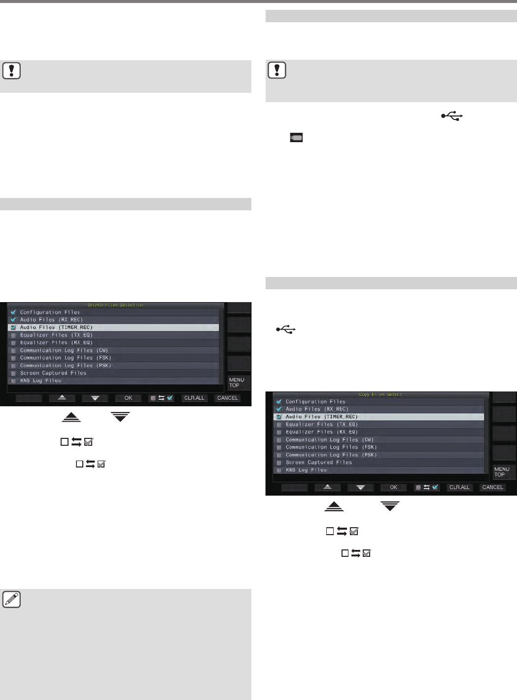
6Access the removable device named “TS-890” from
the PC and copy the files or folders to the PC.
7After copy is complete, remove the removable
device (“TS-890”) safely from the PC.
●The files may not be copied successfully if the proper
steps to remove the device safely from the PC are not
observed.
8Press F4 [EXIT].
A confirmation screen on the batch deletion of files is displayed.
Items for which the checkboxes are selected on the screen for
selecting the files to copy can be deleted from the built-in
memory.
•Pressing and holding F4 [(DELETE)] executes the file
deletion operation.
•Pressing F7 [KEEP] leaves the files intact and returns the
display to the USB/File Management menu screen.
Deleting Files (Built-in Memory)
Follow the steps below to delete settings data or audio data from
the built-in memory. Deletion will apply to the function folders that
contain the corresponding files.
1Select “Delete Files (Internal Memory)” in the USB/
File Management menu.
2Press F4 [SELECT].
A screen for selecting the files to delete is displayed.
.
3Press F2 [ ]/ F3 [ ] or turn the [MULTI/CH]
control to select the items to delete.
4Press F5 [ ] to select the checkbox to the left
of the settings data name.
•Pressing F5 [] again deselects the checkbox. (Files
are not deleted.)
•Pressing F6 [CLR.ALL] deselects all the checkboxes.
•Select at least 1 item to delete.
•Pressing F7 [CANCEL] returns the display to the USB/File
Management menu screen.
5Press F4 [OK].
A file deletion confirmation screen is displayed.
6Press F4 [OK].
File deletion starts.
•Pressing F7 [CANCEL] returns the display to the file
deletion confirmation screen without deleting the files.
●When the built-in memory is selected as the destination
for saving files and the item to be deleted coincides with
an item for which manual recording or CW/RTTY/PSK
communication log recording is in progress, pressing F4
[OK] will result in an error and an “unable to delete”
message will be displayed.
●When a remote user is logged in via the KNS function
and the communication log is set to ON, selecting “KNS
Log Files” as an item to delete and pressing F4 [OK] will
result in an error and an “unable to delete” message will
be displayed.
Formatting a USB Flash Drive
The USB flash drive needs to be formatted by this transceiver
before it can be used. USB flash drives cannot be recognized if
they are not formatted by this transceiver.
●Formatting a USB flash drive using this transceiver
erases all data that exist in the USB flash drive. As such,
make sure to save the necessary data to a PC or other
external data storage devices before deleting.
1Insert the USB flash drive into the (USB-A)
connector.
<< >> starts to blink and lights up when the USB flash drive
is recognized by this transceiver.
2Select “Format USB Flash Drive” in the USB/File
Management menu.
3Press F4 [SELECT] to start formatting.
•A message to confirm the start of the formatting process is
displayed.
•Pressing F7 [CANCEL] ends the operation without
formatting the USB flash drive.
4Press F4 [OK].
When formatting is complete, the display returns to the USB/
File Management menu screen.
Copying Files to a USB Flash Drive
Files that are stored in the built-in memory of this transceiver can
be copied to a USB flash drive.
•Insert a USB flash drive formatted using this transceiver into
(USB-A).
1Select “Copy Files to USB Flash Drive” in the USB/
File Management menu.
2Press F4 [SELECT].
A screen for selecting the files to copy is displayed.
.
3Press F2[ ] or F3[ ], or turn the [MULTI/CH]
control to select the items to copy.
4Press F5 [ ] to select the checkbox to the left
of the settings data name.
•Pressing F5 [] again deselects the checkbox. (Files
are not copied.)
•Pressing F6 [CLR.ALL] deselects all the checkboxes.
•The items that can be copied are the same as those in the
table in “Copying Files to a PC”. Select at least 1 item.
5Press F4 [OK].
Copy starts and a copy in progress screen is displayed.
After file copying is complete, a confirmation screen on the
batch deletion of files is displayed.
Items for which the checkboxes are selected on the screen for
selecting the files to copy can be deleted from the built-in
memory.
•Pressing and holding F4 [(DELETE)] executes the file
deletion operation.
•Pressing F7 [KEEP] leaves the files intact and returns the
display to the USB/File Management menu screen.
USB/FILE MANAGEMENT 11
11-5
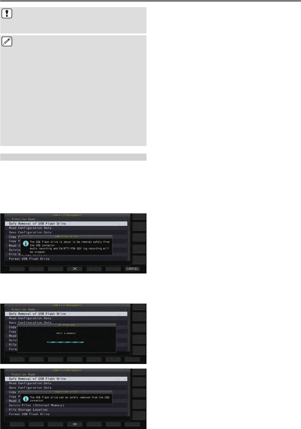
●If the number of files exceeds 255 while copy is in
progress, the copy operation stops.
●When removing the USB flash drive, make sure to
execute “Safe Removal of USB Flash Drive”.
●If the same file on the source location is also found in the
destination USB flash drive, the latter file will be overwritten.
●If there is insufficient memory in the USB flash drive for
all the files to be copied, pressing F4 [OK] will result in
an error and “Insufficient Memory Size” will be displayed
on the screen.
●Pressing F7 [CANCEL] while copying is in progress
starts the cancel copy operation. When the cancel copy
operation is complete, the display returns to the USB/File
Management menu screen.
●While manual recording or CW/RTTY/PSK
communication log recording is in progress, selecting a
file to copy followed by pressing F4 [OK] will result in an
error and an “unable to copy” message will be displayed.
●When a remote user is logged in via the KNS function
and the communication log is set to ON, selecting “KNS
Log Files” and pressing F4 [OK] will result in an error and
an “unable to copy” message will be displayed.
Safely Removing the USB Flash Drive
When removing a USB flash drive from this transceiver, make sure
to follow the steps below to remove the device safely. Failure to do
so may result in the damage of the USB flash drive, settings data
files and audio data files or malfunction of this transceiver.
1Select “Safe Removal of USB Flash Drive”.
2Press F4 [SELECT].
A message on the safe removal of the USB flash drive is displayed.
.
•Pressing F7 [CANCEL] ends the operation without
performing the safe removal of the USB flash drive.
3Press F4 [OK].
Safe removal starts.
.
.
4Press F4[OK].
The USB flash drive can now be removed.
11 USB/FILE MANAGEMENT
11-6
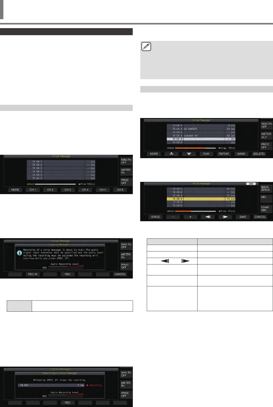
Recording/Playing a Voice Message
This transceiver comes with a function for recording, playing and
transmitting standard voice messages as well as a function for
recording and playing audio that is transmitted or received.
Voice messages can be recorded to a maximum of 6 channels.
Messages recorded with a microphone can also be transmitted.
•This is handy during DX-pedition or contest operation where
repeated calls need to be made over a long period of time or for
adjusting an antenna or transceiver by transmitting a test radio
wave. The maximum recording time is 100 seconds. In other
words, recording to all the channels is possible up to a duration
of 100 seconds in total.
Recording a Voice Message
Follow the steps below to record a voice message to a voice
message channel (TX CH 1 to TX CH 6).
1Press the mode key to select either SSB, FM or AM
mode.
2Press F2 [TX MSG] to display the Voice Message
screen.
.
3Press and hold the function key (F2 [CH 1] to F7 [CH
6]) corresponding to the channel for storing the
voice message.
A message to confirm the start of voice message recording
appears.
•If F2 [CH 1] to F7 [CH 6] is not displayed, press F1
[MORE].
.
4Press F2 [REC IN].
•Pressing F2 [REC IN] each time switches the audio input
path.
Setting
Value MIC (default)/ ACC 2/ USB/ LAN
•To adjust the recording level, turn the [MIC] control. Adjust
the recording level while monitoring the peak recording level
on the recording level meter such that the peak does not
show in the red zone.
•Pressing F7 [CANCEL] ends the recording.
5Press and hold F4 [REC].
Recording continues and the recording time of the voice
message is displayed while F4 [REC] is pressed and held
down.
.
6Releasing F4 [REC] ends the recording and saves
the voice message.
●Recording ends automatically when the total recording
time of all channels exceeds 100 seconds even when
the F4 [REC] key is still pressed down.
●This transceiver does not allow continuous voice
message recording using multiple channels.
●When a new message is recorded, the voice message
that already exists on the channel will be overwritten.
Registering a Name for a Voice Message
Recorded voice messages can be assigned with a name.
1Press F2 [TX MSG] to display the Voice Message
screen.
.
2Select the voice message to name.
3Press F6 [NAME].
Doing so enables editing of the voice message name.
.
4Use the function keys, [MULTI/CH] control or USB
keyboard to input the characters.
Key Operation
F1 [SPACE] Inserts a space.
F2 [–]/ F3 [+] Selects a character.
F4 [ ]/ F5 [ ] Moves the cursor.
F [BACK SPACE] Deletes the character to the left of the
cursor.
F [DEL] Deletes the character to the right of the
cursor.
F [CHAR]
Switches the type of character to edit.
Pressing the key each time switches the
selection in the following sequence:
ABC (upper case) → abc (lower case)
→ !”# (symbols) → ABC (upper case)
5Press F6 [SAVE] to save the name of the voice
message.
•Pressing F7 [CANCEL] discards the input characters and
exits the editing mode for the voice message name.
VOICE MESSAGE/AUDIO FILE 12
12 VOICE MESSAGE/AUDIO FILE
12-1
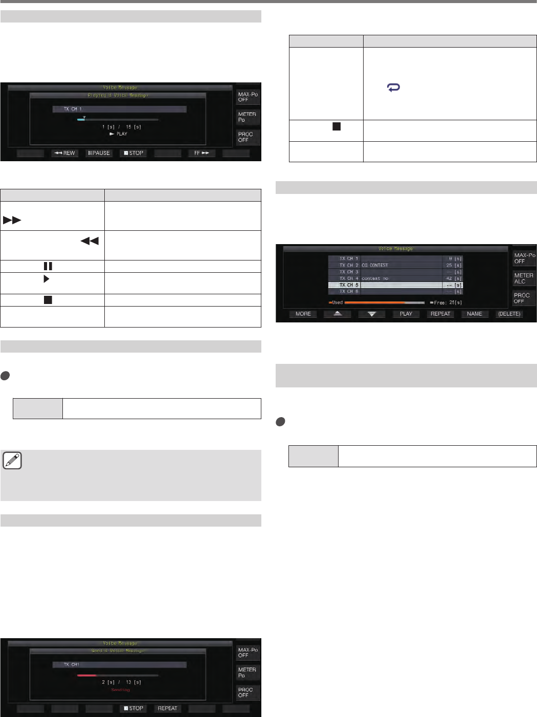
Playing Back a Voice Message
Follow the steps below to play back a recorded voice message.
1Select a voice message channel to play back.
2Press F4 [PLAY] to play back the voice message.
The voice message playback screen appears.
.
The following operations are possible while a voice message is
being played back.
Operation Behavior
Press and hold F6 [FF
].
Fast forwards the voice message.
•Release the key to resume playback at
the normal speed.
Press and hold F2 [
REW] .
Rewinds the voice message.
•Release the key to resume playback at
the normal speed.
Press F3 [ PAUSE]. Pauses the voice message.
Press F3 [ PLAY] while
playback is paused Resumes playback from the position where
it was paused.
Press F4 [ STOP]. Stops the playback of voice message.
Press [ESC]. Closes the Voice Message screen and
ends the playback.
Adjusting the Playback Volume
Configure the volume level when playing back a voice message.
Configure in Menu [1-01] “Voice Message Volume
(Play)”
Setting
Value Off/ 1 to 10 (default) to 20 (1 step)
Configuring to a larger value raises the volume level. Selecting
“Off” mutes the playback sound.
●When TX monitor is ON, the voice message is output as
the TX monitor audio so the volume changes in tandem
with the TX monitor level.
●For more details on adjusting the TX monitor level,
please refer to (8-3).
Sending a Voice Message
A recorded voice message can be transmitted while it is being
played back.
1Press F2 [TX MSG] to display the Voice Message
screen.
2Press and hold the function key (F2 [CH 1] to F7 [CH
6]) corresponding to the channel that contains the
voice message to be transmitted.
•A voice message playback screen is displayed, and the
voice message is transmitted.
.
•Turning the [MIC/PITCH] control while transmission of a
voice message is in progress enables the gain level of the
microphone used exclusively for the voice message to be
adjusted.
•The following operations are possible while a voice
message is being transmitted.
Operation Behavior
Press F5
[REPEAT].
Plays back and transmits the voice message
repeatedly. Pressing F5 [REPEAT] again ends
repeat playback and transmission, and returns
this transceiver to the RX mode.
•<< >> lights up while repeat playback is
in progress.
•The time interval for repeating the
transmission can be configured.
Press F4 [
STOP]. Stops transmission of the voice message and
closes the voice message transmission screen.
Press [ESC]. Closes the Voice Message screen and ends
transmission of the voice message.
Deleting a Voice Message
Follow the steps below to delete a recorded voice message.
1Select a channel that contains the voice message
to be deleted.
.
2Press and hold F7 [(DELETE)] to delete the selected
voice message.
Configuring the Time Interval for Repeated
Transmission
The time interval for repeating playback of a voice message can
be configured.
Configure in Menu [5-16] “CW/Voice Message
Retransmit Interval Time”
Setting
Value 0 to 10 (default) to 60 [s] (1 step)
Configuring to a larger value lengthens the playback interval.
12 VOICE MESSAGE/AUDIO FILE
12-2

Recording/Playing Voice Communication
This transceiver can be used to record voice communication or
play back the recordings.
Recording functions that can be used on this transceiver are as
follows.
Manual Recording
•Voice recordings up to 9 hours per file can be stored in the built-
in memory of this transceiver. As the built-in memory is also
used by other functions, the maximum recording time varies
depending on the remaining space available.
•Voice data up to 18 hours per file can be recorded when a USB
flash drive is used. If recording continues for a duration longer
than 18 hours per file, a new file will be created upon reaching
18 hours and recording will continue.
Full-time Recording
This recording function records the most recent voice data up to
the last 30 seconds to an audio file.
Timer Recording (USB Flash Drive Only)
This function records audio based on the preconfigured duration
and conditions. For more details on the timer recording operation,
please refer to Chapter 14 “CLOCK DISPLAY/TIMER”.
●If DC power is turned off during recording, the saving of
the file recorded at that time is not guaranteed. To turn
off the power during recording, do so using [ ] on the
front panel.
Manual Recording
The [ ] and [ ] keys can be used to start or stop recording of
communication using this transceiver.
1Press [ ] to start recording.
•“ REC” appears on the screen and the [REC] LED lights
up.
.
2Press [ ] to end the recording.
•“ REC” disappears from the screen and the [REC] LED
light goes off.
●When the remaining memory at the destination for
storing the file runs out while recording is in progress, a
“recording end” tone is output and the recording ends
automatically.
Full-time Recording
This recording function records the most recent communication
audio up to the last 30 seconds. This allows the user to check the
content of the most recent voice communication.
Configuring the Maximum Duration for Full-time
Recording
Configure in Menu [6-00] “Playback Time (Full-time
Recording)”
Setting
Value Last 10/ Last 20/ Last 30 (default) [s]
Saving Full-time Recording Audio
Press and hold [ ].
•The <<[REC]>> LED starts to blink for 1 second.
•The most recent audio until [ ] is pressed and held down
is recorded to the built-in memory or USB flash drive
according to the preconfigured maximum duration (number
of seconds) for full-time recording.
●Pressing F1 [RX PLAY] or F2 [TX MSG] does not
activate full-time recording if manual recording is in
progress.
●When the remaining memory at the destination for
storing the file is running out, a “Insufficient memory
space” message is displayed on the screen and
recording ends automatically.
●When the squelch did not open for a duration longer than
the preconfigured recording time, pressing and holding
[ ] does not activate recording.
Audio Recording in Tandem with Squelch
Recording of the RX audio can be activated in tandem with the
squelch operation.
Configure in Menu [6-01] “Recording with Squelch”
Setting
Value Off/ On (default)
Off: Performs recording even when a signal is not received.
On: Performs recording only when the squelch opens. (Closing the
squelch while recording is in progress pauses the recording
operation.)
●When “Recording with Squelch” is enabled, the “
REC” remains lit even when the squelch is closed. Also,
the “ REC” remains lit even if the squelch has not
opened at all. (In this case, a file will not be generated
when recording ends.)
VOICE MESSAGE/AUDIO FILE 12
12-3
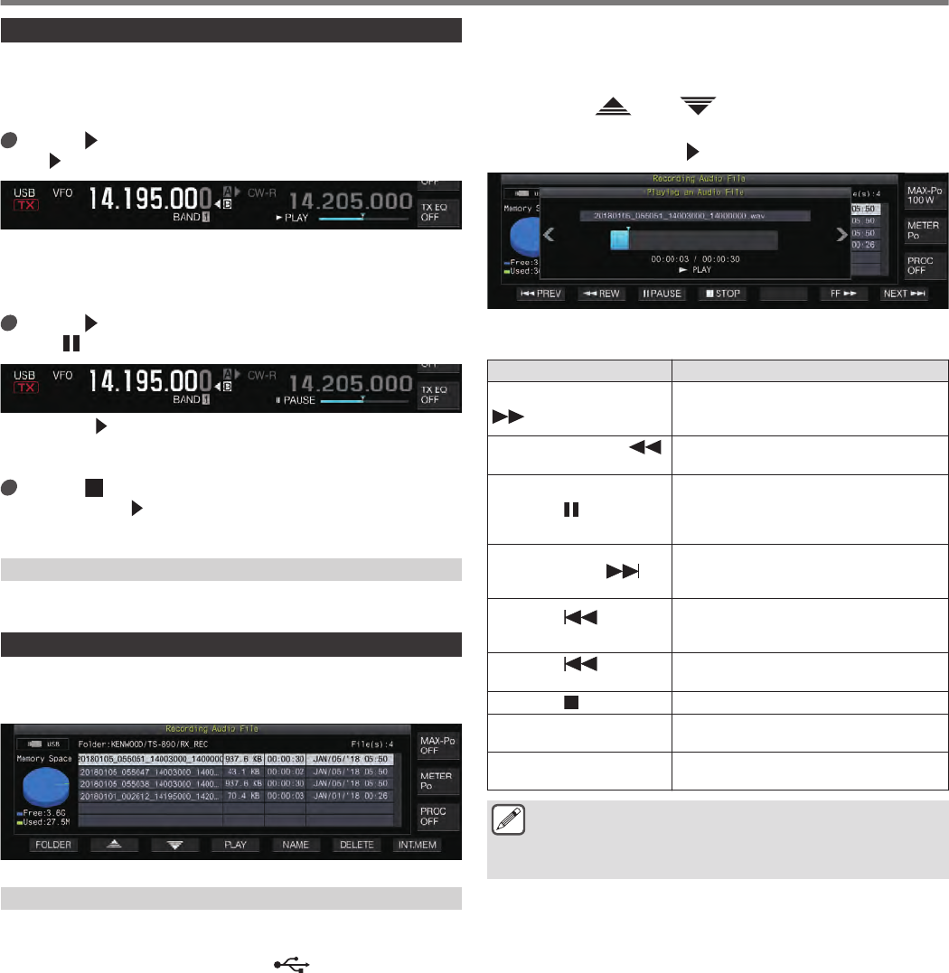
Quick Playback
This function allows playback of the most recent manual recording
or full-time recording audio file.
Playback
Press [ ] to play back the most recent audio file.
•“ PLAY” and the playback progress bar appear.
.
•The selected audio file is played back when the audio file
screen is displayed.
Pausing Playback
Press [ ] during playback to pause the audio file.
•<< >> lights up.
.
Pressing [ ] again resumes the playback.
Stopping Playback
Press [ ] to stop playback of the audio file.
•The light of “ PLAY” and that of the playback progress bar
goes off.
Adjusting the Playback Volume
Turn the [AF] control to adjust the playback volume.
Audio Recording File Screen
Audio files saved via manual recording, full-time recording or timer
recording can be operated on this screen.
.
Playing Back an Audio File
Follow the steps below to play back audio files that are stored in
the built-in memory or a USB flash drive.
To use a USB flash drive, insert it into (USB-A) in advance
and check to ensure that it is recognized by this transceiver.
1Press F1 [RX PLAY] to display the audio recording
file screen.
2Press F7 [INT.MEM] or F7 [USB MEM] to toggle
between the screens for the built-in memory and
USB flash drive.
•Pressing F7 [INT.MEM] displays the audio file (built-in
memory) screen. “Internal” is shown on the screen.
•Pressing F7 [USB MEM] displays the audio file (USB flash
drive) screen. “USB” is shown on the screen.
•To change the folder to browse, press F1 [FOLDER].
•Files recorded using the timer-recording reservation
function are stored in the TIMER_REC folder, while all other
recordings are stored in the RX_REC folder.
3Press F2[ ]/ F3[ ] or turn the [MULTI/CH]
control to select the audio file to play back.
4Press F4 [PLAY] or [ ] to play back the audio file.
.
The following operations are possible while an audio file is being
played back.
Operation Behavior
Press and hold F5 [FF
].
Fast forwards the audio file. Release the
key to resume playback at the normal
speed.
Press and hold F2 [
REW] . Rewinds the audio file. Release the key to
resume playback at the normal speed.
Press F3 [ PAUSE].
Pauses the audio file. Pressing F3
[PLAY] while playback is paused resumes
playback from the position where it was
paused.
Press F7 [NEXT ]. Plays back from the beginning of the audio
file that immediately precedes the audio file
that is current playing.
Press F1 [ PREV]
twice quickly.
Plays back from the beginning of the audio
file that immediately follows the audio file
that is current playing.
Press F1 [ PREV]
once. Plays back the currently playing audio file
again from the beginning.
Press F4 [ STOP]. Stops playback of the audio file.
Press [ESC]. Exits the audio file playback screen and
audio recording file list screen.
Turn [MULTI/CH]. Cueing is possible when 2 or more audio
files are saved.
●RX audio is muted during playback of an audio file.
Transmission is also disabled.
●When removing the USB flash drive, make sure to
execute “Safe Removal of USB Flash Drive”. (See 11-6)
12 VOICE MESSAGE/AUDIO FILE
12-4
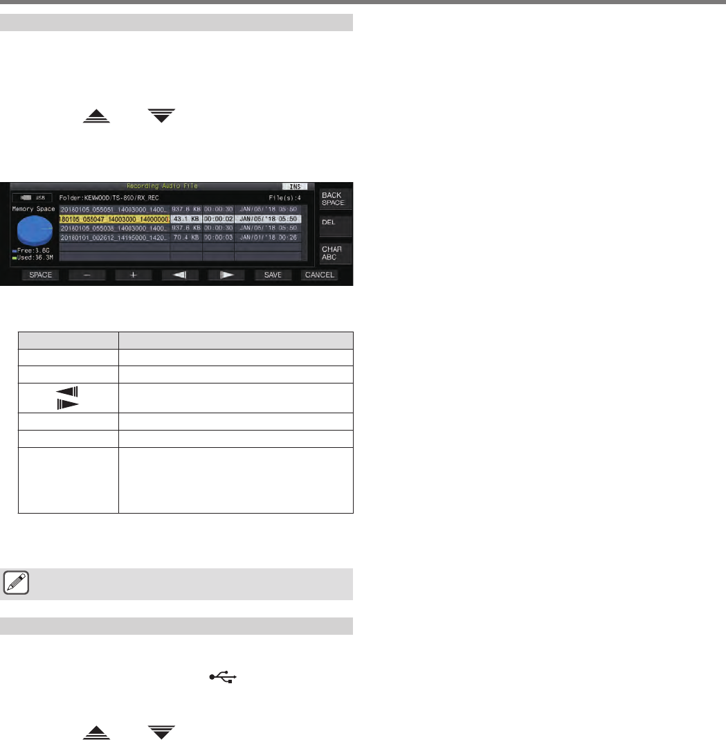
Renaming an Audio File
The name of audio files saved via manual recording, full-time
recording or timer recording can be changed.
1Press F1 [RX PLAY] to display the audio recording
file screen.
2Press F2[ ]/ F3[ ] or turn the [MULTI/CH]
control to select the audio file for which the name
is to be changed.
3Press F5 [NAME].
.
4Use the function keys, [MULTI/CH] control or USB
keyboard to enter a name.
Key Operation
F1 [SPACE] Inserts a space.
F2 [–]/ F3 [+] Selects a character.
F4 [ ]/ F5
[ ] Moves the cursor.
F [BACK SPACE] Deletes the character to the left of the cursor.
F [DEL] Deletes the character to the right of the cursor.
F [CHAR]
Switches the type of character to edit. Pressing
the key each time switches the selection in the
following sequence:
ABC (upper case) → abc (lower case) → !”#
(symbols) → ABC (upper case)
5Press F6 [SAVE] to save the file name.
•Pressing F7 [CANCEL] discards the information entered
and exits the audio file name input mode.
●When removing the USB flash drive, make sure to
execute “Safe Removal of USB Flash Drive”. (See 11-6)
Deleting an Audio File
Follow the steps below to delete audio files that are stored in the
built-in memory or a USB flash drive.
To use a USB flash drive, insert it into (USB-A) in advance
and check to ensure that it is recognized by this transceiver.
1Press F1 [RX PLAY] to display the audio file screen.
2Press F2[ ]/ F3[ ] or turn the [MULTI/CH]
control to select the audio file to delete.
3Press F6 [DELETE].
A message to confirm deletion of the file is displayed.
4Press F4 [OK] to delete the audio file.
•Pressing F7 [CANCEL] returns the display to the audio file
screen without deleting the audio file.
VOICE MESSAGE/AUDIO FILE 12
12-5

.
12-6
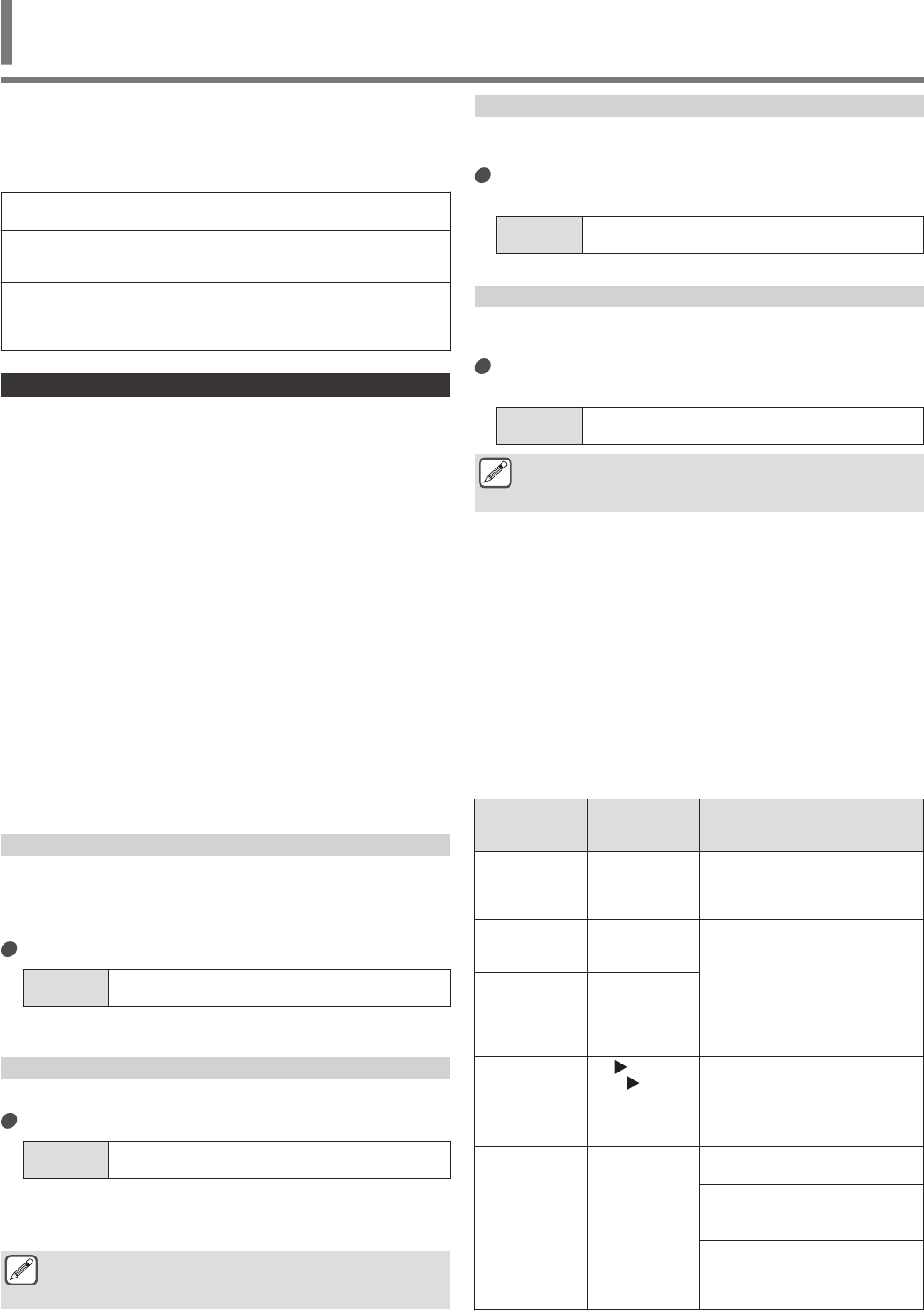
This transceiver comes with a voice guidance that sends out a
voice notification of the operating status that is displayed on the
screen.
The voice guidance content is described in the following style in
this manual.
Voice The actual voice guidance content is enclosed
in quotation marks (“ ”).
Numeric values and
alphabets
Content of the voice guidance is described
collectively using numeric values and
alphabets.
Options
The actual voice guidance content is listed up
using [ ]. Each option is separated from the
other by a slash (/), and only one of the options
will be uttered at a time.
Voice Guidance
Pressing the PF key that is assigned with the voice guidance
function outputs a guidance voice on the operating status from the
built-in speaker.
The following 4 types of voice guidance are available.
VOICE1
Announces the current frequency and operating status.
The default setting is [PF A].
VOICE2
Announces the status of the S meter and power meter.
The default setting is [PF B].
VOICE3
Announces the status of the meter selected in F [METER] except
for the power meter.
The default setting is [PF C].
Auto Announce
Announces automatically when a specific operation is performed
or upon entering a specific status. The default setting is “OFF”.
Adjusting the Voice Guidance Volume
Adjust the volume level of the voice guidance. When the voice
guidance volume is set to OFF, pressing the corresponding PF key
does not output a voice guidance announcement from this
transceiver.
Configure in Menu [1-03] “Voice Guidance Volume”
Setting
Value Off/ 1 to 10 (default) to 20 (1 step)
•Configuring to a larger value raises the volume level.
Adjusting the Voice Guidance Speed
Adjust the speed of the announcement.
Configure in Menu [1-04] “Voice Guidance Speed”
Setting
Value 1 (default) to 4 (1 step)
•The larger the value, the faster the speed of the
announcement. (1:1x (normal speed), 2:1.15x, 3:1.3x,
4:1.45x)
●Increasing the voice guidance speed may sometimes
cause the audibility to deteriorate depending on the
content of the announcement.
Configuring the Voice Guidance Language
The voice guidance language can be configured to English or
Japanese.
Configure in Menu [1-05] “User Interface Language
(Voice Guidance & Messages)”
Setting
Value English (default)/ Japanese
Auto Voice Guidance
When auto voice guidance is set to ON, a voice guidance is
automatically output when a specific operation is performed.
Configure in Menu [1-06] “Automatic Voice
Guidance”
Setting
Value Off (default)/ On
●When this function is in the OFF status, turning on the
power of this transceiver while pressing down the [PF
A] key turns on [Auto Voice Guidance].
•When auto voice guidance is ON, voice guidance is output
in the following sequence.
*1 : Announces the VFO (“A” or “B”) that is currently operating.
*2 : “X” is uttered when XIT is ON, “R” is uttered when RIT is ON,
and “XR” is announced followed by the RIT/XIT frequencies
when both XIT and RIT are ON. The numeric values of the
“RIT/XIT frequencies” are announced in sequence starting
from the kHz digit. “Point” is uttered after the kHz value. If the
frequency is a negative value, “Minus” is uttered at the
beginning.
*3 : [USB/ LSB/ CW/ FSK/ PSK/ FM/ AM/ USB Data/ LSB Data/
CW Reverse/ FSK Reverse/ PSK Reverse/ FM Data/ AM
Data]
*4 : When in the SWL mode, “SWL” is added to the beginning of
the announcement.
Operation on
This
Transceiver Key Operation Content of Voice Guidance
When powering
on -
Announces the data used for
operation regardless of the status of
the setting screen. (Refer to “Voice
1”.)
Switching
between VFO A
and VFO B [A/B]
Outputs announcements according
to the operating status after
switching. (Refer to “Voice 1”.)
Switching
between the
VFO mode and
memory channel
mode
[M/V]
Memory shift [M V]
F [M VFO]
Announces the data used for
operation. (Refer to “Voice 1”.)
Switching to the
quick memory
channel mode [Q-MR] Announces the details of the quick
memory channel mode. (Refer to
“Voice 1”.)
Switching of the
memory channel
in the memory
mode (except
when the
Memory
Channel List
screen is
displayed)
Turn
[MULTI/CH]
Blank channel:
“Channel” + Number + “Blank”
Simplex mode:
“Channel” + Number + Frequency +
([X/ R/ XR] + RIT/XIT Frequency) *2
Split mode:
“Channel” + Number + “Split” +
Frequency + ([X/ R/ XR] + RIT/XIT
Frequency) *2
VOICE GUIDANCE 13
13 VOICE GUIDANCE
13-1

Operation on
This
Transceiver Key Operation Content of Voice Guidance
Switching of
quick memory
channel
Turn
[MULTI/CH]
Simplex mode:
“Quick” + Number + [A/ B]*1
Frequency + ([X/ R/ XR] + RIT/XIT
Frequency) *2
Split mode:
“Quick” + Number + “Split” + [A/
B]*1 Frequency + ([X/ R/ XR] +
RIT/XIT Frequency) *2
Entering a
frequency using
the numeric
keypad
[ENT]
“Enter”
Entering a
channel number
using the
numeric keypad
Press a key on
the numeric
keypad Numeric value that is entered
Switching the
frequency entry
history
Turn
[MULTI/CH] Frequency entry history
Switching
frequency lock [LOCK] “Lock” + [On/ Off]
Switching split
operation [SPLIT] “Split” + [On/ Off]
Configuring split
frequency via
numeric keypad
operation
Press and hold
[SPLIT] “Split” + “Enter”
When [0] is first
pressed “Minus”
Numeric keypad
“TX” + [Plus/ Minus]* + Numeric
value that is entered + “Kilohertz”
* Pressing the keys from [1] to [9]
adds a “Plus” utterance, while
pressing [0] + ([1] to [9]) adds a
“Minus” utterance.
When
configuration of
the split
frequency using
the Tuning
control is
complete
[SPLIT] (After
configuration
using the Tuning
control)
“TX” + Finalized TX frequency
Change in the
low cutoff
frequency
Turn [LO/
WIDTH] “Low” + Frequency
Change in the
width Turn [LO/
WIDTH] “Width” + Options
Change in the
high cutoff
frequency Turn [HI/SHIFT] “High” + Options
Change in the
shift frequency Turn [HI/SHIFT] “Shift” + Options
Change in the
TX output power Turn [POWER]
•When drive output is ON: TX
power + Value
•When drive output is OFF:
When the transverter is ON and “TX
Power Down with Transverter
Enabled” is “On”: “TX power” + 5
In all other cases: “TX power” +
Value (The value shows a value up
to the TX output power limit if the TX
output power limiter is operating.)
[MIC/PITCH]
control
operation
Turn [MIC/
PITCH]
•When adjusting microphone
gain: “Mic. Gain” + Value
•When adjusting the speech
processor output level:
“Processor”+ “Out” + Value
* No voice is output during
adjustment of the sidetone/pitch
frequency.
Operation on
This
Transceiver Key Operation Content of Voice Guidance
[DELAY] control
operation Turn [DELAY]
•When adjusting the break-in
delay time: “Full” + “Break-in” in
the case of FULL-BK
DELAY: “Break-in delay” +
Displayed value in the case of 1 to
20
•When adjusting VOX delay:
“VOX delay” + Value
[KEY] control
operation Turn [KEY] •When adjusting the keying
speed: Keying speed + Value
Timer function
ON/OFF
operation F [TIMER] “Timer” + [On/ Off]
Dimmer
switching F [DIMMER]
F2 [DIMMER] “D” + Numeric value (single digit)
Antenna
switching F [ANT] “Antenna” + Number
Band Direct
selection
Band Direct
keys (including
operation of
[GENE])
Frequency
Calling up the
preconfigured
emergency
frequency
PF [Emergency
Frequency] “Emergency” + Frequency
Meter switching F [METER]
Analog meter display (TX digital
meter OFF): [Power/ SWR/ ID/
Processor/ ALC/ VD]
Analog meter display (TX digital
meter ON): [SWR/ ID/ Processor/
VD/ TMP]
Digital meter display: [SWR/ ID/
Processor/ VD/ TMP]
Mini digital meter display: [Power/
SWR/ ID/ Processor/ ALC/ VD/
TMP]
Error/warning
messages (none)
Error or warning + Number
For more details on the number,
please refer to the “Error
Messages” and “Warning
Messages” lists.
Voice 1
Voice 1 announces the displayed frequency, channel number,
details of the respective configuration modes as well as the status
of menu settings.
Announces the digits of the VFO and memory channel frequencies
which are higher than 10 Hz when fine tuning is OFF. “Point” is
uttered after announcing the MHz digits. When a channel that does
not contain any operating data is selected during memory scroll,
“Blank” is uttered.
Press the PF key that is assigned with “VOICE1”.
Announces the operating status. Announces the setting value
while configuration is in progress on the configuration screen.
●Pressing the PF key that is assigned with “VOICE1”,
“VOICE2” or “VOICE3” during the announcement stops
the announcement.
●Altering the frequency by turning the Tuning or
[MULTI/CH] control during an announcement stops the
announcement.
●For more details on how to change the assignment of PF
keys, please refer to “PF Keys (Programmable Function
Keys)”.
●Announcement is not output while scanning is in
progress.
13 VOICE GUIDANCE
13-2

Pressing “VOICE1” outputs an announcement as follows. The content of the announcement varies with the screen that is being displayed.
Announcements Related to Operating Frequency (Including Content of Auto Announcements)
Screen Operation/Status Content of Announcement
VFO mode *4 Simplex mode [A/ B]*1 Frequency + ([X/ R/ XR] + RIT/XIT Frequency) *2
Split mode “Split” + [A/ B]*1 Frequency + ([X/ R/ XR] + RIT/XIT Frequency) *2
Memory channel mode *4
Blank channel “Channel” + Number + “Blank”
Simplex mode “Channel” + Number + Frequency + ([X/ R/ XR] + RIT/XIT Frequency) *2
Split mode “Channel” + Number + Frequency + ([X/ R/ XR] + RIT/XIT Frequency) *2
Quick memory channel
mode *4
Simplex mode “Quick” + Number + [A/ B] + Frequency + ([X/ R/ XR] + RIT/XIT Frequency) *2
Split mode “Quick” + Number + “Split” + [A/ B]*1 Frequency + ([X/ R/ XR] + RIT/XIT Frequency) *2
During frequency entry
Before numeric keypad input Enter
Input in progress The numeric value that is most recently input (“Point” is also uttered after announcing
the MHz digits. A pause is inserted for the kHz digit.)
During confirmation [A/ B] + Frequency
When entry is canceled No announcement
When entry history is selected Frequency entry history
During entry of memory
channel no.
During 1-digit input “Enter” + Number
During 2-digit input 1st digit + 2nd digit + [Frequency/Blank]
When configuring the split
frequency
Pressing and holding SPLIT “Split” + “Enter”
When [0] is first pressed “Minus”
When the numeric keypad ([1]
to [9]) is operated
“TX” + [Plus/ Minus]* + Numeric value that is entered + Kilohertz
* Pressing the keys from [1] to [9] adds a “Plus” utterance, while pressing [0] + ([1] to
[9]) adds a “Minus” utterance.
Announcements during Display of Configuration Screens (Including Content of Auto Announcements)
Screen Operation/Status Content of Announcement
Auto mode
Screen launch “Auto” + Frequency at the top of the list + Mode *3
When [VOICE1] is pressed “Auto” + Frequency
When a selection is made Selected frequency + Mode *3
When frequency is copied to the
list “Copy” + Copied frequency + Mode *3
Switching between ON/OFF “Auto” + [On/ Off]
AGC settings
When screen is displayed or
when [VOICE1] is pressed “AGC” + [Fast/ Middle/ Slow/ Off] (+ Value)
When value is changed Value
When AGC speed is switched [Fast/ Middle/ Slow] + Value
AGC OFF “AGC” + “Off”
Equalizer
When screen is displayed or
when [VOICE1] is pressed [RX/TX] + “Equalizer” + (HB1/ HB2/ FP/ BB1/ BB2/ F/ C/ U1/ U2/ U3)
When a selection is made via
key operation [HB1/ HB2/ FP/ BB1/ BB2/ F/ C/ U1/ U2/ U3]
Equalizer adjustment
When screen is displayed or
when [VOICE1] is pressed [RX/TX] + “Equalizer” + “Adjustment”
When a selection is made [0/0.3/0.6/0.9/1.2/1.5/1.8/2.1/2.4/2.7/3.0/3.3/3.6/3.9/4.2/4.5/4.8/5.1] (+ [+/-]) + Value +
dB ([+/-] is not uttered when it is 0 dB.)
When value is changed via key
operation (+/-) + Value + dB ([+/-] is not uttered when it is 0 dB)
Initialization No announcement
Confirmation of equalizer
copy When screen is displayed or
when [VOICE1] is pressed “Copy” + “Are you Sure?”
VOICE GUIDANCE 13
13-3

Screen Operation/Status Content of Announcement
Selection of file to read
When the RXEQ screen is
displayed or when [VOICE1] is
pressed
“File” + “List” + “RX” + “Equalizer”
When the TXEQ screen is
displayed or when [VOICE1] is
pressed
“File” + “List” + “TX” + “Equalizer”
When the DATA screen is
displayed or when [VOICE1] is
pressed
“File” + “List” + “Data”
When a selection is made Year + Month + Day + Time (Announces the time stamp of the file)
When the file deletion
confirmation screen is
displayed or when [VOICE1] is
pressed
“Delete” + “Are you Sure?”
Name editing “Edit”
When the file browsing location
is changed [USB/ Internal]
Selection of data to read
(DATA)
When screen is displayed or
when [VOICE1] is pressed “Read” + “Data” + “Selection”
When a selection is made
(environment-dependent) “ENV” + [On/ Off]
When a selection is made (CW) “CW” + “Message” + [On/ Off]
When a selection is made (voice
message) “Voice” + “Message” + [On/ Off]
Switching between ON/OFF [On/ Off]
Processing (without
CANCEL key) When screen is displayed or
when [VOICE1] is pressed “Please wait” (Announcement is not output when reading data with RXEQ/TXEQ.)
Data reading complete When screen is displayed or
when [VOICE1] is pressed “Completed”
Request to get ready the
USB flash drive When screen is displayed or
when [VOICE1] is pressed “USB” + “Connect”
Data saving complete When screen is displayed or
when [VOICE1] is pressed “Completed”
TX audio source input
settings
When screen is displayed or
when [VOICE1] is pressed “Moduration-Source” + [Mic. + PTT/ Data + PTT]
Switching method of
transmission [Mic. + PTT/ Data + PTT]
Specification of audio input line
(Front/Rear) (</>) [F/ R]
Front input selection F4
[SELECT] [Off/ Mic.]
Rear input selection F4
[SELECT] [Off/ ACC 2/ USB/ LAN]
Switching DATA VOX between
ON/OFF “Data” + “VOX” + [Off/ ACC two/ USB/ LAN]
VOX level configuration
When screen is displayed or
when [VOICE1] is pressed [VOX gain/ Anti- + VOX gain/ VOX delay] + [Mic./ ACC two/ USB/ LAN] + Value
Switching of audio source input [Mic./ ACC two/ USB/ LAN]
Switching the parameter to
configure [VOX gain/ Anti- + VOX gain/ VOX delay]
Increasing or decreasing the
setting value Value
Reset to default value No announcement
TX output power limiter
configuration
When screen is displayed or
when [VOICE1] is pressed [TX power + Limit + [SSB/ CW/ FSK PSK/ FM AM/ Data]/ [TX Tune] + Band + Value
The band is [1.8/ 3.5/ 5/ 7/ 10/ 14/ 18/ 21/ 24/ 28/ 50] + Mega Hertz
TX output power type selection [TX power + Limit + [SSB/ CW/ FSK PSK/ FM AM/ Data] / TX Tune]
Band selection [1.8/ 3.5/ 5/ 7/ 10/ 14/ 18/ 21/ 24/ 28/ 50/ 70] + Mega Hertz
Increasing or decreasing TX
output power Value
Reset to default value No announcement
Speech processor
configuration
When screen is displayed or
when [VOICE1] is pressed “Processor” + [Soft/Hard] + [In/Out] + Value
Effect selection [Soft/ Hard]
Switching between “Input” and
“Output” [In/ Out]
Increasing or decreasing the
value Value
13 VOICE GUIDANCE
13-4

Screen Operation/Status Content of Announcement
CW message (paddle
version)
When screen is displayed or
when [VOICE1] is pressed
(deselected)
“CW” + “Message”
When screen is displayed or
when [VOICE1] is pressed
(selected)
“Channel” + Number (+ “Repeat”) (+ “Blank”)
Switching of repeat mode “Repeat” + [Off/ On]
Switching of channel Number + “Repeat” + “Blank”
Switching of playback list No announcement
Delete No announcement
Standby for CW message
(paddle) registration When screen is displayed or
when [VOICE1] is pressed No announcement
During CW message
registration When [VOICE1] is pressed No announcement
CW message (text version)
When screen is displayed or
when [VOICE1] is pressed
(deselected)
“CW” + “Message”
When screen is displayed or
when [VOICE1] is pressed
(selected)
“Channel” + Number (+ “Repeat”) (+ “Blank”) (+ Contest number)
Switching of repeat mode “Repeat” + [Off/ On]
Switching of channel Number (+ “Repeat”) (+ “Blank”) (+ Contest number)
Switching of playback list No announcement
Delete No announcement
Subtraction of contest number Contest numbers
Channel message editing “Edit”
RTTY communication When screen is displayed or
when [VOICE1] is pressed “RTTY” + “Communication”
PSK communication When screen is displayed or
when [VOICE1] is pressed “PSK” + “Communication”
RTTY/PSK message
When screen is displayed or
when [VOICE1] is pressed
(deselected) [RTTY/ PSK] + “Message”
When screen is displayed or
when [VOICE1] is pressed
(deselected)
“Channel” + Number + “Auto” + “TX” + “RX”
Switching of channel Number
AUTO TX mode switching “Auto” + “TX” + [Off/ On]
AUTO RX mode switching “Auto” + “RX” + [Off/ On]
Message editing (including
when [VOICE1] is pressed) “Message” + “Edit”
Log file selection
When screen is displayed or
when [VOICE1] is pressed
In the case of log file selection screen (CW):
“Log” + “File” + “CW”
In the case of log file selection screen (RTTY):
“Log” + “File” + “RTTY”
In the case of log file selection screen (PSK):
“Log” + “File” + “PSK”
When a selection is made Year (2018 to 2099) + Month + Day + Time
File deletion confirmation “Delete” + “Are you Sure?”
Name editing “Edit”
When the file browsing location
is changed [USB/ Internal]
Log View When screen is displayed or
when [VOICE1] is pressed “Log” + “View”
FM tone frequency
configuration
When screen is displayed or
when [VOICE1] is pressed “Tone” + Frequency
Change in frequency Frequency
Start of TONE scanning
During TONE scanning or when
[VOICE1] is pressed
“Tone” + “Scan”
End of TONE scanning Frequency
FM CTCSS frequency
configuration
When screen is displayed or
when [VOICE1] is pressed “CTCSS” + Frequency
Change in frequency Frequency
Start of CTCSS scanning
During CTCSS scanning or
when [VOICE1] is pressed
“CTCSS” + “Scan”
End of CTCSS scanning Frequency
VOICE GUIDANCE 13
13-5

Screen Operation/Status Content of Announcement
FM cross tone frequency
configuration
When screen is displayed or
when [VOICE1] is pressed “Cross-Tone” + [Tone/ CTCSS] + Frequency
TONE/CTCSS switching [Tone/ CTCSS]
Change in frequency Frequency
RX filter configuration
When screen is displayed or
when [VOICE1] is pressed “RX” + “Filter” + [A/ B/ C] + [R/ IF/ AF] + Options
Switching of filter [A/ B/ C]
Switching of roofing filter [Auto/ 270 + Hertz/ 500 + Hertz/ 2.7 + Kilohertz/ 6 + Kilohertz/ 15 + Kilohertz]
Switching of shape factor [Soft/ Medium/ Sharp]
Configuring or clearing preset
passband characteristics No announcement
Switching of audio filter width [Narrow/ Medium/ Wide]
Audio peak filter
configuration
When screen is displayed or
when [VOICE1] is pressed “APF” + [Narrow/ Medium/ Wide]
When a selection is made [Narrow/ Medium/ Wide]
Switching of shift frequency “Shift” (+ [+/-]) + Value + “Hertz”
Switching of gain level “Gain” (+ [+]) + Value + “dB”
NB1/ NR1/ NR2 level
configuration
When screen is displayed or
when [VOICE1] is pressed
“Noise blanker” + “1” + Value
“Noise reduction” + “1” + Value
“Noise reduction” + “2” + Value
Reset to default value No announcement
Switching of setting value Value
NB2 level configuration
When screen is displayed or
when [VOICE1] is pressed
“Noise blanker” + “2” + “A” + Value or “Noise blanker” + “2” + “B” + “Level” + Value or
“Noise blanker” + “2” + “B” + “Width” + Value or “Noise blanker” + “2” + “B” + “Depth” +
Value
Switching of type [A/ B]
When a selection is made [Level/ Width/ Depth]
Reset to default value No announcement
Switching of value Value
(Standard size) Bandscope
+ Waterfall When screen is displayed or
when [VOICE1] is pressed “Bandscope”
(Standard size) Bandscope
screen When screen is displayed or
when [VOICE1] is pressed “Bandscope”
(Enlarged size) Bandscope
+ Waterfall When screen is displayed or
when [VOICE1] is pressed “Bandscope”
Audio scope When screen is displayed or
when [VOICE1] is pressed “Audioscope”
Multi scope
Bandscope (upper screen)/
audio scope (lower screen)
When screen is displayed or
when [VOICE1] is pressed “Audioscope”
13 VOICE GUIDANCE
13-6

Screen Operation/Status Content of Announcement
Memory channel list
When screen is displayed or
when [VOICE1] is pressed
During normal selection
Blank channel: “Memory” + “List” + Number + “Blank”
Simplex mode: “Memory” + “List” + Number + Frequency
Split mode: “Memory” + “List” + Number + “Split” + Frequency
During selection of data writing destination
Blank channel: “Memory” + “In” + Number + “Blank”
Simplex mode: “Memory” + “In” + Number + Frequency
Split mode: “Memory” + “In” + Number + “Split” + Frequency
When a selection is made Blank channel: Number + Blank
Simplex mode: Number + Frequency
Split mode: Number + Split + Frequency
Registration or pasting of data No announcement
Input of start frequency for
specific band segments (Input
of end frequency)
“End” + “Frequency” + Current frequency
Erasing channel data No announcement
Name input “Edit”
Lockout mode switching “Lockout” + [On/ Off]
Confirmation for deletion of
all quick memory data When screen is displayed or
when [VOICE1] is pressed “Quick memory” + “Clear” + “Are you Sure?”
Group configuration for
Memory Scan
When screen is displayed or
when [VOICE1] is pressed “Memory” + “Scan” + “Group” + Number + [On/ Off]
When a selection is made Number + [On/ Off]
Switching between ON/OFF [On/ Off]
Switching between All ON/All
OFF
“Select” + “All”
“Clear” + “All”
Configuration of segment for
Program Scan
When screen is displayed or
when [VOICE1] is pressed Program Scan: “Program” + “Scan” + “Channel”+ Number + [On/ Off]
VFO Scan: “VFO” + “Scan”
When a selection is made Number + [On/ Off]
Switching between ON/OFF [On/ Off]
Switching between VFO Scan/
Program Scan [VFO + Scan/ Program + Scan]
Switching between All ON/All
OFF
“Select” + “All”
“Clear” + “All”
Configuration of Program
Slow Scan points
When screen is displayed or
when [VOICE1] is pressed “Program” + “Slow” + “Scan” + Operating frequency
During configuration of point
frequency No announcement
Batch delete “Clear” + “All”
Voice message
When screen is displayed or
when [VOICE1] is pressed “Voice” + “Message”
When the editing screen is
displayed or when [VOICE1] is
pressed
Blank channel: “Message” + Number + “Blank”
Registered channel: “Message” + Number (+ “Repeat”)
Switching of channel to edit Blank channel: Number + “Blank”
Registered channel: Number (+ “Repeat”)
Switching of repeat mode “Repeat” + [Off/ On]
Deletion No announcement
Name registration
(Including when [VOICE1] is
pressed)
“Edit”
Voice message recording
standby
When screen is displayed or
when [VOICE1] is pressed “Record” + [Mic./ ACC two/ USB/ LAN]
Switching of audio source input [Mic./ ACC two/ USB/ LAN]
VOICE GUIDANCE 13
13-7

Screen Operation/Status Content of Announcement
Recording file (built-in
memory)
When screen is opened or when
[VOICE1] is pressed
When browsing audio files:
“Audio” + “File”
When browsing audio files of timer recordings:
“Audio” + “File” + “Timer”
When a selection is made Year (2018 to 2099) + Month + Day + Time
Folder switching (recording file/
timer)
When browsing the built-in memory: Same as when a screen is displayed
When browsing the USB flash drive: Refer to “When a screen is displayed” in “Recording
file (USB flash drive)”
Switching memory Same as when the recording file (USB flash drive) screen is launched
However, if the USB flash drive is not connected, refer to the “Request to get ready the
USB flash drive” screen
File deletion confirmation
(Including when [VOICE1] is
pressed)
“Delete” + “Are you Sure?”
Editing of file name “Edit”
Request to get ready the USB
flash drive
(Including when [VOICE1] is
pressed)
“USB” + “Connect”
Recording file (USB flash
drive)
When screen is opened or when
[VOICE1] is pressed When browsing audio files: “Audio” + “File” + “USB”
When browsing audio files of timer recordings: “Audio” + “File” + “USB” + “Timer”
When a selection is made Year (2018 to 2099) + Month + Day + Time
Switching memory Refer to the Recording file (built-in memory) screen
Folder switching (between
TIMER_REC and RXREC)
When browsing a USB flash drive: Same as when a screen is displayed
When browsing the built-in memory: Refer to “When a screen is displayed” in
“Recording file (built-in memory)”
File deletion confirmation
(Including when [VOICE1] is
pressed)
“Delete” + “Are you Sure?”
Name editing “Edit”
LAN menu
When screen is displayed or
when [VOICE1] is pressed “LAN” + “Menu” + Item number (1 digit) + Settings
Switching of setting item Item number (1 digits) + Settings
Start of setting value editing,
movement of selection, input of
setting value Value of selected position
Switching of setting item
(Related to address)
Item number (1 digit) + nnn + “Point” + nnn + “Point” + nnn + “Point” + nnn
However, content is as follows when nnn is blank:
Item number (1 digit) + “Blank”
Switching of setting item
(Related to ID/Pass) Item number (1 digit)
Start of setting value editing,
movement of selection (related
to address) Value of selected position
Input of setting value (related to
address) Numeric value that is entered
Selection of setting value
(related to address) Selected value
CLOCK menu top When a screen is displayed “Clock” + “Menu” + “Group” + Group number (1 digit)
Group selection Number
CLOCK menu items display
When screen is opened or when
[VOICE1] is pressed “Clock” + “Menu” + Item number (2 digit) + Settings
Item selection Item number (2 digits) + Settings
Start of Date and Time
configuration “Edit”
Start of configuration No announcement
Change in setting value Description
Acquisition of NTP date/time
data When a screen is displayed “Clock” + “Update”
Acquisition of NTP date/time
data is complete When screen is displayed or
when [VOICE1] is pressed “Completed”
Acquisition of NTP date/time
data failed When screen is displayed or
when [VOICE1] is pressed “Error” + Number
Timer configuration
When screen is displayed or
when [VOICE1] is pressed “Programmable” + “Timer” + Options
When the sleep timer settings
are changed “Sleep Timer” + Options
13 VOICE GUIDANCE
13-8

Screen Operation/Status Content of Announcement
Program timer configuration
When screen is displayed or
when [VOICE1] is pressed
“Programmable” + “Timer” + [On/ Off]
“Programmable” + “Timer” + “Repeat” + [On/ Off]
“Programmable” + “Timer” + Day + [On/ Off]
“Programmable” + “Timer” + “Mode” + [Timer Off/ On/ Off/ Both/ Record]
“Programmable” + “Timer” + “Start” + “Hour” + Numeric value (2 digits)
“Programmable” + “Timer” + “Start” + “Minute” + Numeric value (2 digits)
“Programmable” + “Timer” + “End” + “Hour” + Numeric value (2 digits)
“Programmable” + “Timer” + “End” + “Minute” + Numeric value (2 digits)
“Programmable” + “Timer” + Frequency + Timer RX mode
When a selection is made
Announces the status of the selected position
“Timer” + [On/ Off]
“Repeat” + [On/ Off]
Day + [On/ Off]
“Mode” + [Timer Off/ On/ Off/ Both/ Record]
“Start” + “Hour” + Numeric value (2 digits)
“Start” + “Minute” + Numeric value (2 digits)
“End” + “Hour” + Numeric value (2 digits)
“End” + “Minute” + Numeric value (2 digits)
Frequency + Timer RX mode
When a setting value is input Numeric value that is entered
Switching between ON/OFF [On/ Off]
Mode switching [Timer Off/ On/ Off/ Both/ Record]
Change in selected setting
([MULTI/CH] control/F4[+]/
F5[–]/numeric keypad) Description
Program timer configuration
is complete When screen is displayed or
when [VOICE1] is pressed “Completed”
Menu top
When screen is displayed or
when [VOICE1] is pressed “Menu” + “Group” + Group number (1 digit)
Group selection “Group” + Group number (1 digit)
Upon entering SWL mode “SWL” + “On”
When SWL mode is OFF “SWL” + “Off”
Menu items display
When screen is displayed or
when [VOICE1] is pressed “Menu” + Group number (1 digit) + Item number (2 digits) + Setting
When a menu is selected Item number (2 digits) + Settings
During start of parameter
editing
(Including when [VOICE1] is
pressed)
“Edit”
When a setting value is selected No announcement
When a setting value is altered Selected value
[GROUP ]“Group” + Group number (1 digit)
[GROUP ]“Group” + Group number (1 digit)
USB/file management menu
When screen is displayed or
when [VOICE1] is pressed
Announces the selected function item
“USB” + “File” + “Menu” + [Remove/ Read + Configuration/ Save + Configuration/ Copy
+ File + PC/ Copy + File + USB/ Read + File/ Delete + File/ File + Save/ Format]
When an item is selected [Remove/ Read + Configuration/ Save + Configuration/ Copy + File + PC/ Copy + File
+ USB/ Read + File/ Delete + File/ File + Save/ Format]
Selection of destination to
save files
When screen is displayed or
when [VOICE1] is pressed “File” + “Save” + [Internal/ USB]
When switching the selection
option [Internal/ USB]
Selection of items to copy
When screen is displayed or
when [VOICE1] is pressed
Announces the selected function item
“Copy” + “File” + “Select” + [Configuration/ Audio/ Timer + Audio/ TX + Equalizer/ RX +
Equalizer/ CW + Log/ RTTY + Log/ PSK + Log/ S + C/ KNS + Log]
When an item is selected [Configuration/ Audio/ Timer + Audio/ TX + Equalizer/ RX + Equalizer/ CW + Log/ RTTY
+ Log/ PSK + Log/ S + C/ KNS + Log]
Switching between check and
uncheck [Off/ On]
VOICE GUIDANCE 13
13-9

Screen Operation/Status Content of Announcement
Selection of items to delete
When screen is displayed or
when [VOICE1] is pressed
Announces the selected function item
“Delete” + “File” + “Select” + [Configuration/ Audio/ Timer + Audio/ TX + Equalizer/ RX
+ Equalizer/ CW + Log/ RTTY + Log/ PSK + Log/ S + C/ KNS + Log]
When an item is selected [Configuration/ Audio/ Timer + Audio/ TX + Equalizer/ RX + Equalizer/ CW + Log/ RTTY
+ Log/ PSK + Log/ S + C/ KNS + Log]
* S+C: Screen Captured Files
Switching between check and
uncheck [Off/ On]
Formatting confirmation When screen is displayed or
when [VOICE1] is pressed “Format” + “Are you Sure?”
When “formatting in
progress” screen is
displayed or during other
ongoing processes in
general
When screen is displayed or
when [VOICE1] is pressed “Please wait”
Unmount confirmation When screen is displayed or
when [VOICE1] is pressed “Remove” + “Are you Sure?”
Unmount is complete When screen is displayed or
when [VOICE1] is pressed “Completed”
RESET menu items display When screen is displayed or
when [VOICE1] is pressed
“Menu Reset”
“Memory Channel Reset”
“VFO Reset”
“Standard Reset”
“Full Reset”
Standard reset confirmation When screen is displayed or
when [VOICE1] is pressed “Standard Reset” + “Are you Sure?”
Full reset confirmation When screen is displayed or
when [VOICE1] is pressed “Full Reset” + “Are you Sure?”
VFO reset confirmation When screen is displayed or
when [VOICE1] is pressed “VFO Reset” + “Are you Sure?”
Memory reset confirmation When screen is displayed or
when [VOICE1] is pressed “Memory Channel Reset” + “Are you Sure?”
Menu reset confirmation When screen is displayed or
when [VOICE1] is pressed “Menu Reset” + “Are you Sure?”
Reset in progress When screen is displayed or
when [VOICE1] is pressed “Please wait”
Advanced menu items
display
When screen is displayed or
when [VOICE1] is pressed “Advanced” + “Menu” + Item number (from 1 digit)
When a selection is made Item number (from 1 digits) + Settings
Advanced menu adjustment
When screen is displayed or
when [VOICE1] is pressed No announcement
Change in setting value Value
Touchscreen adjustment in
progress
When screen is displayed (No
voice is output when [VOICE1]
is pressed)
“Touchscreen” + “Calibration”
Advanced menu license
display When screen is displayed or
when [VOICE1] is pressed “License”
Version display for
advanced menu firmware When screen is displayed or
when [VOICE1] is pressed Numeric value + “Point” + 2-digit numeric value
Switching of operating
environment data When screen is displayed or
when [VOICE1] is pressed “A” + Waiting time + “B” + “Are you Sure?”
Error/warning message When screen is displayed or
when [VOICE1] is pressed [Error/ Warning] + Number
AGC quick recovery
configuration
When screen is displayed or
when [VOICE1] is pressed “AGC Quick Recovery” + [Off/ On] (+ Value)
Switching between ON/OFF [On/ Off]
Change in threshold level Value
Carrier level configuration
When screen is displayed or
when [VOICE1] is pressed “Carrier” + Value
Change in carrier level Value
TX monitor level
configuration
When screen is displayed or
when [VOICE1] is pressed “TX monitor” + Value
Change in TX monitor level Value
13 VOICE GUIDANCE
13-10

Screen Operation/Status Content of Announcement
CW communication
When screen is displayed or
when [VOICE1] is pressed “CW” + “Communication”
Contest number decrement Subtracted contest number
Scope range configuration in
Fixed mode When screen is displayed or
when [VOICE1] is pressed “Bandscope” + “Configuration”
TX output power limiter OFF
confirmation When screen is displayed or
when [VOICE1] is pressed “TX power” + “Limit” + “Off” + “Are you Sure?”
Dimmer configuration
When screen is displayed or
when [VOICE1] is pressed
“D” + “Menu” + Value (1 to 100)
* D: Dimmer
When the position to configure
is selected
(When F3 [ ]/ F4 [ ] is
pressed)
[D/L] + Value
*D: Display/ L: LED
Altering of value Value
Linear amplifier menu
configuration
When screen is displayed or
when [VOICE1] is pressed
“Linear Amplifier” + Target bands of linear amplifier menu + Function name of focusing
position + Setting
Band selection [HF/ 50/ 70 (E type only) + Mega Hertz]
Linear amplifier ON/OFF [Off/On]
Linear amplifier TX control [Low/ High]
Linear amplifier TX delay
ON/OFF [Off/ On]
Linear amplifier TX delay time
(CW/FSK/PSK) [5/ 10/ 15/ 20/ 25/ 30/ 35/ 40]
Linear amplifier TX delay time
(SSB/AM/FM) [5/ 10/ 15/ 20/ 25/ 30/ 35/ 40/ 45/ 50]
Linear amplifier relay control [Off/ On]
Linear amplifier external ALC
voltage [-1/ -2/ -3/ -4/ -5/ -6/ -7/ -8/ -9/ -10/ -11/ -12]
KNS information When screen is displayed or
when [VOICE1] is pressed “KNS” + “Connect” + [Off / User name]
KNS configuration When screen is displayed or
when [VOICE1] is pressed
When a selection is made
“KNS” + “Configuration” + Item number (from 1 digit) + Settings
KNS Users List
When screen is displayed or
when [VOICE1] is pressed “KNS” + “User” + “List” + User name of selected item*
When a selection is made User name of selected item*
* The registered user name is uttered one character at a time. Characters that cannot
be uttered will be inserted with a pause. Blank is uttered if a user name is not registered.
KNS user registration
When screen is displayed or
when [VOICE1] is pressed “KNS” + “User” + “List” + User name of selected item*
When a selection is made
Name of selected item*
* The content of the announcement for the item name is as follows.
“User Name”: “User”
“Passwoard”: “PASS” (utters 1 character at a time)
“Description” :“D”
“RX Only”: “RX” + [Off/ On]
“Disabled”: “Disable” + [Off/ On]
Switching between check and
uncheck [Off/ On]
Frequency marker list
When screen is displayed or
when [VOICE1] is pressed
“Frequency” + “Marker” + “List” + [ON/OFF] + [Blank / Frequency] *
* “Blank” if no data is registered. Frequency when data is registered.
When a selection is made [Blank / Marker + Frequency]
Calling up the preconfigured
emergency frequency When screen is displayed or
when [VOICE1] is pressed “Emergency” + “Frequency”
Confirmation for batch
deletion of files When screen is displayed or
when [VOICE1] is pressed “All” + “Delete” + “Are you sure?”
File deletion confirmation When screen is displayed or
when [VOICE1] is pressed “Delete” + “Are you sure?”
●For more details on the option numbers when configuring the PF keys, please refer to “List of Assignable Functions”. When
the higher order digit of the menu number or memory channel number is “0”, “0” will also be uttered.
●When the setting screen overlaps with messages on errors, warnings and other information, announcement will be output for
the error, warning or information message.
●Frequency value in the VFO mode is announced in sequence starting from the highest order digit that is being displayed.
“Point” is uttered as a delimiter for MHz.
VOICE GUIDANCE 13
13-11
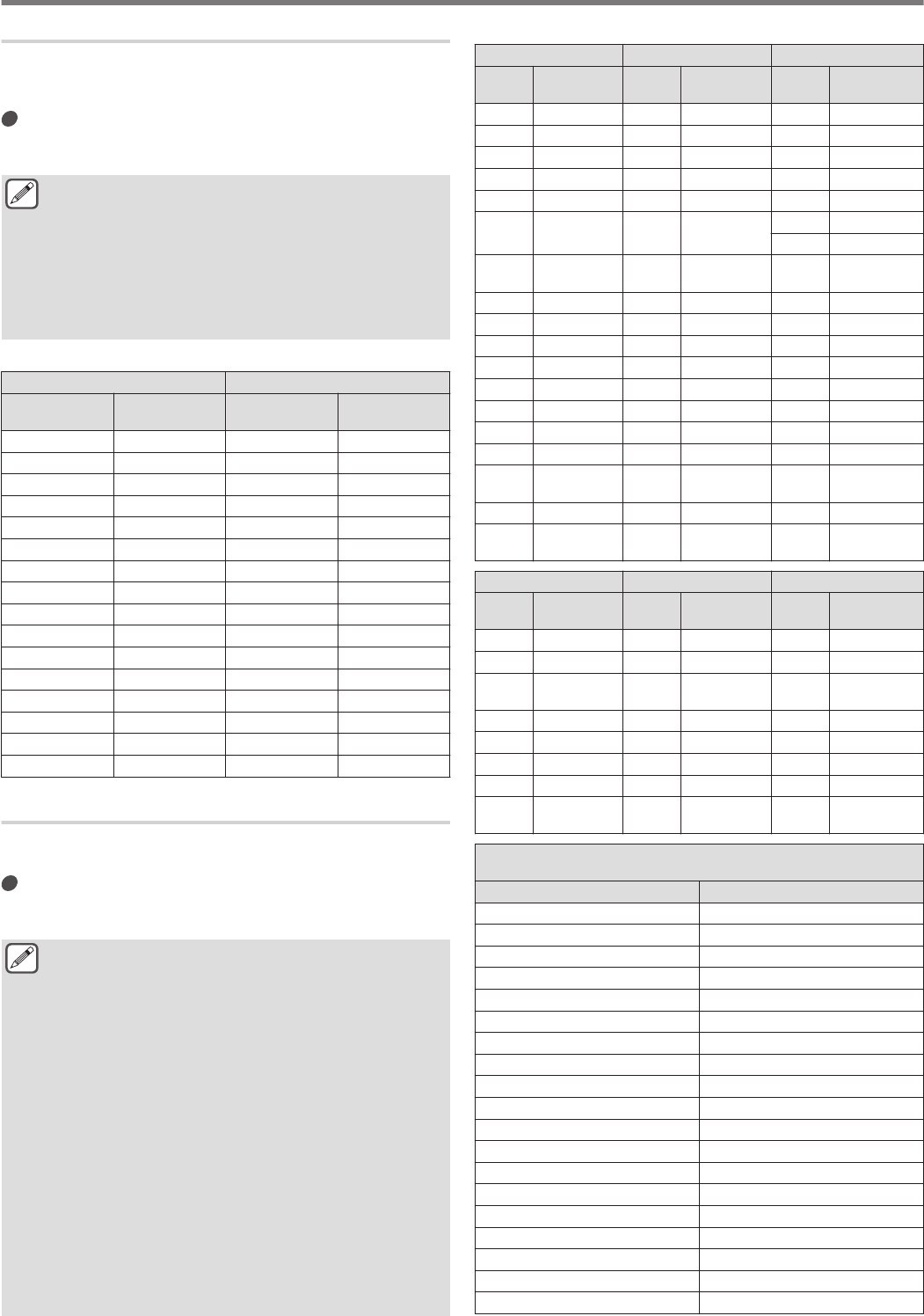
Voice 2
Pressing the key that is assigned with “VOICE2” announces the S
meter and power meter values. For example, “S5” or “20 dB” will
be announced in this case.
Press [PF B] or the PF key that is assigned with
“VOICE2”.
Announces the S meter and power meter values.
●Pressing the PF key that is assigned with “VOICE1”,
“VOICE2” or “VOICE3” during the announcement stops
the announcement.
●For more details on how to change the assignment of PF
keys, please refer to “PF Keys (Programmable Function
Keys)”.
●Even while an analog meter is displayed, the “VOICE2”
announcement changes according to the level when a
digital meter is displayed (dot: 0 to 70).
Content that is announced in the VOICE2 mode is as follows.
S meter Power Meter
Level
Content of
Announcement
Level Content of
Announcement
0 S 0 0 P 0
1 to 4 S 1 1 to 5 P 5
5 to 8 S 2 6 to 10 P 10
9 to 12 S 3 11 to 14 P 17.5
13 to 16 S 4 15 to 19 P 25
17 to 20 S 5 20 to 27 P 37.5
21 to 24 S 6 28 to 35 P 50
25 to 28 S 7 36 to 47 P 75
29 to 32 S 8 48 to 59 P 100
33 to 36 S 9 60 to 65 P 125
37 to 41 10 dB 66 to 70 P 150
42 to 47 20 dB - -
48 to 52 30 dB - -
53 to 58 40 dB - -
59 to 64 50 dB - -
65 to 70 60 dB - -
Voice 3
Pressing the key that is assigned with “VOICE3” announces the
meter values.
Press [PF C] or the PF key that is assigned with
“VOICE3”.
Announces the meter value at the time when the key is pressed.
●VOICE3 makes announcement only during
transmission.
●Pressing the PF key that is assigned with “VOICE1”,
“VOICE2” or “VOICE3” during the announcement stops
the announcement.
●For more details on how to change the assignment of PF
keys, please refer to “PF Keys (Programmable Function
Keys)”.
●Even while an analog meter is displayed, the “VOICE3”
announcement changes according to the level when a
digital meter is displayed (dot: 0 to 70).
●When the meter selected is PWR meter, the
announcement is the same as that of the PWR meter in
VOICE2.
●Pressing [VOICE3] while the voice message recording
standby screen or the voice message recording in
progress screen is displayed announces the value
(recording level) of the “Recording Level Meter”.
●Pressing [VOICE3] during configuration of the
microphone gain in Advanced Menu [10] announces the
value of the level meter.
Content that is announced in the VOICE3 mode is as follows.
SWR Meter COMP Meter ALC Meter
Level
Content of
Announcement
Level
Content of
Announcement
Level
Content of
Announcement
0 to 1 R 1.0 0 C 0 dB 0 A 0
2 R 1.1 1 to 9 C 5 dB 1 to 2 A 1
3 to 4 R 1.2 10 to 19 C 10 dB 3 to 4 A 2
5 R 1.3 20 to 34 C 15 dB 5 to 6 A 3
6 to 7 R 1.4 35 to 50 C 20 dB 7 to 8 A 4
8 to 9 R 1.5 51 to 57 C 25 dB 9 to 10 A 5
11 to 12 A 6
10 to 11 R 1.6
58
onwards
C OVER 13 to 14 A 7
12 to 13 R 1.7
15 to 16 A 8
14 to 15 R 1.8 17 to 18 A 9
16 to 17 R 1.9 19 to 20 A 10
18 to 21 R 2.0 21 to 22 A 11
22 to 27 R 2.5 23 to 24 A 12
28 to 36 R 3.0 25 to 26 A 13
37 to 42 R 4.0 27 to 28 A 14
43 to 47 R 5.0 29 to 30 A 15
48
onwards
R OVER 31 to 32 A 16
33 to 34 A 17
35
onwards
A OVER
ID Meter TEMP Meter VD Meter
Level
Content of
Announcement
Level
Content of
Announcement
Level
Content of
Announcement
0 to 9 I 2.5 0 to 25 T LOW
Up to 46
V LOW
10 to 17 I 5 26 to 60 T MID 47 to 48 V 10
18 to 26 I 7.5
61
onwards
T HIGH 49 to 51 V 11
27 to 35 I 10 52 to 55 V 12
36 to 44 I 12.5 56 to 58 V 13
45 to 52 I 15 59 to 61 V 14
53 to 60 I 17.5 62 to 64 V 15
61
onwards
I 20
65
onwards
V HIGH
Recording Level Meter/
Audio Lever Meter during FM Microphone Gain Configuration
Level Content of Announcement
0 L 0
1 to 2 L 1
3 to 4 L 2
5 to 6 L 3
7 to 8 L 4
9 to 10 L 5
11 to 12 L 6
13 to 14 L 7
15 to 16 L 8
17 to 18 L 9
19 to 20 L 10
21 to 22 L 11
23 to 24 L 12
25 to 26 L 13
27 to 28 L 14
29 to 30 L 15
31 to 32 L 16
33 to 34 L 17
35 onwards L OVER
13 VOICE GUIDANCE
13-12
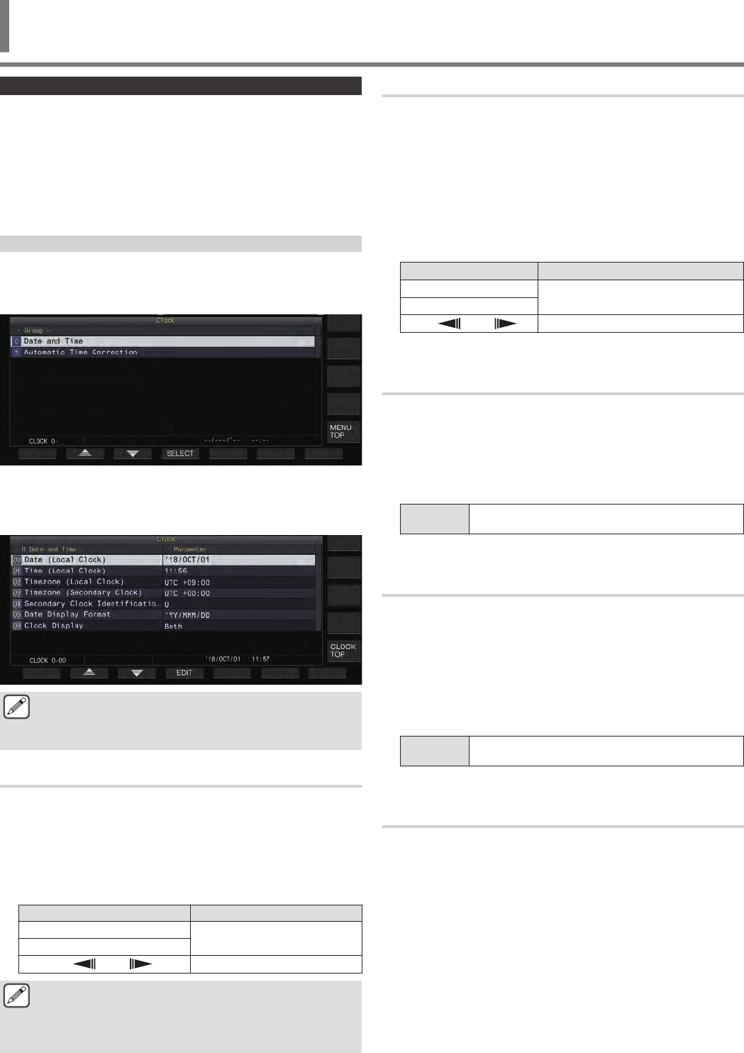
Configuring Date and Time
This transceiver can display 2 types of clocks.
Local Clock
Displays the current date and time.
Auxiliary Clock
Displays information such as the UTC clock.
Displaying the Clock Menu Screen
1Press [MENU] to display the menu screen.
2Press F [CLOCK] to display the Clock menu screen.
.
3Select Clock Menu [0] “Date and Time”.
4Press F4 [SELECT].
The date/time configuration screen is displayed.
.
●Pressing F7 [CANCEL] while the date and time
configurations for Local Clock is still in progress discards
the settings and returns the display to the Date and Time
configuration screen.
Configuring the Local Clock Date
The date of the local clock that is used for display or the time stamp
in files can be configured as follows.
1Select Clock Menu [00] “Date (Local Clock)”.
2Press F4 [EDIT].
3Use the function keys and the [MULTI/CH] control
to select the date.
Key Behavior
F2 [–]/ F3 [+] Selects a setting value.
[MULTI/CH]
F4 [ ]/ F5 [ ] Moves the cursor.
●The date and time is displayed in the parameter field of
the Clock screen according to the “Date Display
Format” setting.
●The local clock cannot be configured when the auto time
correction function using the NTP server is ON.
4Press F6 [OK].
Configuring the Local Clock Time
Follow the steps below to configure the local clock time. This is
usually configured to the local time of the location where this
transceiver is being operated.
1Select Clock Menu [01] “Time (Local Clock)”.
2Press F4 [EDIT].
3Use the numeric keypad, function keys and the
[MULTI/CH] control to configure the time.
A numeric value can be entered by pressing the corresponding
key on the numeric keypad.
Key/Control Behavior
F2 [–]/ F3 [+] Selects a setting value.
[MULTI/CH]
F4 [ ]/ F5 [ ] Moves the cursor.
4Press F6 [OK].
Configuring the Local Clock Time Zone
Follow the steps below to configure the time zone of the local clock.
1Select Clock Menu [02] “Timezone (Local Clock)”.
2Press F4 [SELECT].
3Press F2 [–]/ F3 [+] or turn the [MULTI/CH] control
to select the time zone of the local clock.
Setting
Value UTC-14:00 to UTC+00:00 (default) to UTC+14:00
(15min/step)
4Press F6 [OK].
Configuring the Auxiliary Clock Time Zone
Follow the steps below to configure the time zone of the auxiliary
clock.
1Select Clock Menu [03] “Timezone (Secondary
Clock)”.
2Press F4 [SELECT].
3Press F2 [–]/ F3 [+] or turn the [MULTI/CH] control
to select the time zone of the local clock.
Setting
Value UTC-14:00 to UTC+00:00 (default) to UTC+14:00
(15min/step)
4Press F6 [OK].
Registering an Auxiliary Clock Identifier
The auxiliary clock can be assigned with a single alphabet as an
identifier.
1Select Clock Menu [04] “Secondary Clock
Identification Letter”.
2Press F4 [EDIT].
3Press F2 [–]/ F3 [+] or turn the [MULTI/CH] control
to select an identifier character.
•“U” is used in the default setting, which stands for
“Coordinated Universal Time (UTC)”.
4Press F6 [OK].
CLOCK DISPLAY/TIMER 14
14 CLOCK DISPLAY/TIMER
14-1
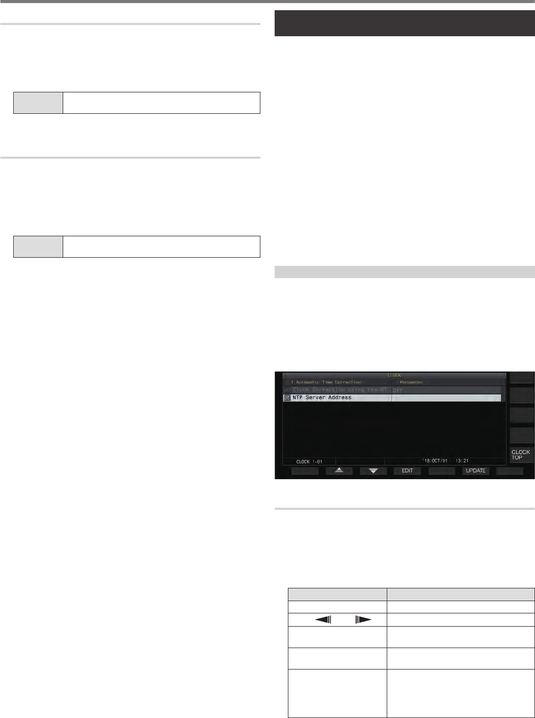
Configuring the Date Display Format
The date display format can be configured as follows.
1Select Clock Menu [05] “Date Display Format”.
2Press F4 [SELECT].
3Select the preferred date display format.
Setting
Value MMM/DD/'YY (K type: default)/ DD/MMM/'YY (E type:
default)/ 'YY/MMM/DD
4Press F6 [OK].
Configuring the Clock Display
Follow the steps below to configure the types and number of clocks
to display.
1Select Clock Menu [06] “Clock Display”.
2Press F4 [SELECT].
3Select the preferred time display format.
Setting
Value Off/ Local Clock/ Secondary Clock/ Both (default)
Off: Does not display the clock.
Local Clock: Displays only the local clock.
Secondary Clock: Displays only the auxiliary clock.
Both: Displays both the local clock and auxiliary clock.
4Press F6 [OK].
Clock Correction Using NTP (Network Time
Protocol)
The NTP server can be used to correct the clock time
automatically. This is done by applying the date and time acquired
from the NTP server to the built-in clock of this transceiver.
The following configuration procedures are needed to make use
of the NTP function.
•Connect this transceiver to a network such as a home LAN via
a LAN cable.
•To make use of an NTP server on WAN, allow communication
to be established via the Network Time Protocol Port (port 123).
For a home LAN that uses a broadband router, ensure that port
123 of the broadband router is open.
•Configure the network on this transceiver.
•Configure the network and IP address on this transceiver. For
more details on the method of configuration, please refer to
“Configuring the IP Address”.
•Configure the address of the NTP server.
•Configure the NTP server address of the time zone configured
for the local clock on this transceiver. For more details on the
method of configuration, please refer to “Configuring the NTP
Server Address”.
Displaying the Auto Correction Configuration Screen
1Press [MENU] to display the menu screen.
2Press F [CLOCK] to display the Clock menu screen.
3Select Clock Menu [1] “Automatic Time
Correction”.
4Press F4 [SELECT].
The auto correction configuration screen is displayed.
.
Configuring the NTP Server Address
Follow the steps below to configure the address of the NTP server.
1Select Clock Menu [01] “NTP Server Address”.
2Press F4 [EDIT].
3Use the function keys, [MULTI/CH] control or USB
keyboard to enter the address of the NTP server.
Key Behavior
F2 [–]/ F3 [+] Selects a character.
F4 [ ]/ F5 [ ] Moves the cursor.
F [BACK SPACE] Deletes the character to the left of the
cursor.
F [DEL] Deletes the character to the right of the
cursor.
F [CHAR]
Switches the type of character to edit.
Pressing the key each time switches the
selection in the following sequence:
ABC (upper case) → abc (lower case)
→ !”# (symbols) → ABC (upper case)
4Press F6 [SAVE] to save the address.
•Pressing F7 [CANCEL] discards the input and restores this
transceiver to the NTP server address setting input mode.
14 CLOCK DISPLAY/TIMER
14-2
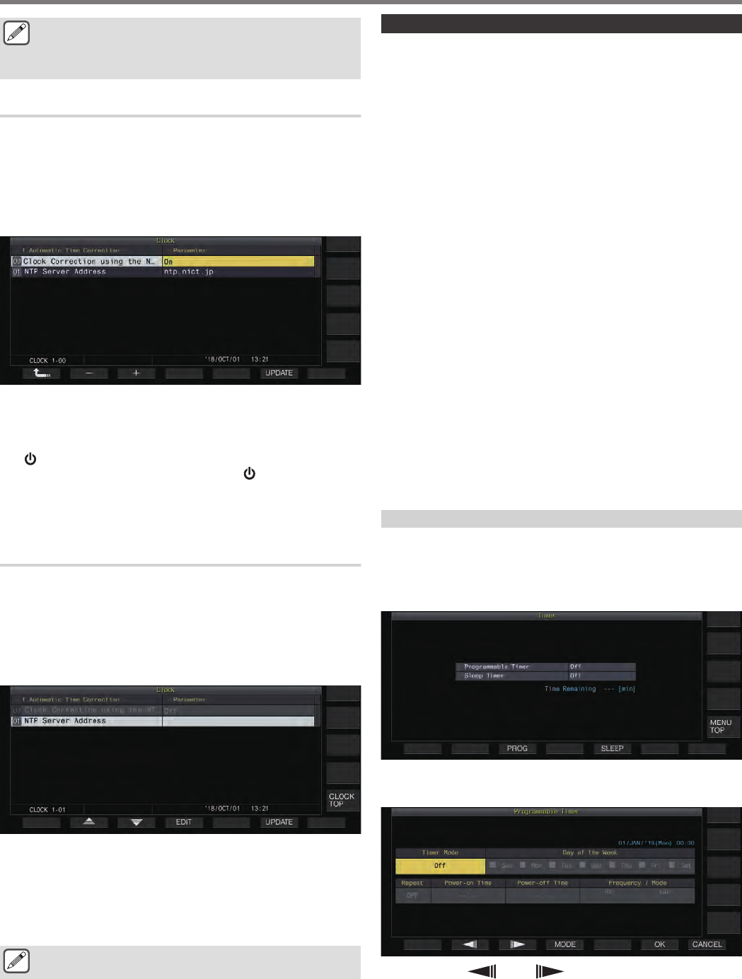
●The response time of the NTP server varies depending
on the condition of the network and the NTP server.
●Search for the NTP server address using “NTP server”
as the keyword.
Turning ON/OFF Auto Clock Correction
The date and time that is configured for the clock of this transceiver
can be corrected by communicating automatically with the NTP
server.
1Select Clock Menu [00] “Clock Correction using the
NTP Server”.
2Press F4 [SELECT].
.
3Press F2 [–]/ F3 [+] to set auto correction to “On” or
“Off”.
When auto correction is set to “On”, communication is
established automatically with the NTP server when the power
() of this transceiver is turned on and correction of the clock’s
date and time is performed. If the power ( ) of this transceiver
is left on, auto correction is performed at an interval of
approximately 24 hours. The default setting is “Off”.
4Press F6 [OK].
Correcting the Date and Time Manually
The date and time that is configured for the clock of this transceiver
can be corrected by connecting this transceiver manually to the
NTP server.
1Select Clock Menu [1] “Automatic Time
Correction”.
2Press F4 [SELECT].
.
3Press F6 [UPDATE].
Communication with the NTP server starts, and the date and
time configured for the clock of this transceiver is corrected.
After correction is complete, a message is displayed to notify
the user that communication with the NTP server has ended.
•Pressing F7 [CANCEL] while acquiring the date and time
via NTP stops the acquisition process.
●The NTP server is a public server, please refrain from
accessing it frequently.
Timer
This transceiver supports programmed operation using the
following timer functions. The frequency and mode can be
configured in the Program Timer screen.
Power ON (Program Timer Configuration Screen)
Turns on this transceiver with the preconfigured frequency and
mode at the preconfigured timing.
Power OFF (Program Timer Configuration Screen)
Turns off this transceiver at the preconfigured time.
Power ON and Power OFF (Program Timer
Configuration Screen)
Turns on or off this transceiver with the preconfigured frequency
and mode and at the preconfigured timing.
Timer Recording (Program Timer Configuration
Screen)
Records RX audio to the built-in memory or a USB flash drive
during the interval between the preconfigured Power-on and
Power-off time.
Sleep Timer (Timer Configuration Screen)
Turns off this transceiver after the preconfigured duration has
elapsed.
APO (Auto Power Off) (Menu [0-32])
Turns off this transceiver if there is no key or control operation for
the preconfigured duration.
Configuring the Program Timer
Follow the steps below to configure the timing for powering on and
off this transceiver as well as the operation of the program timer.
1Press F [TIMER] on the menu screen to display the
Timer configuration screen.
.
2Press F3 [PROG] to display the Programmable
Timer configuration screen.
.
3Press F2 [ ]/ F3 [ ] to select the setting item.
4Use the function keys and the [MULTI/CH] control
to configure the program timer.
CLOCK DISPLAY/TIMER 14
14-3
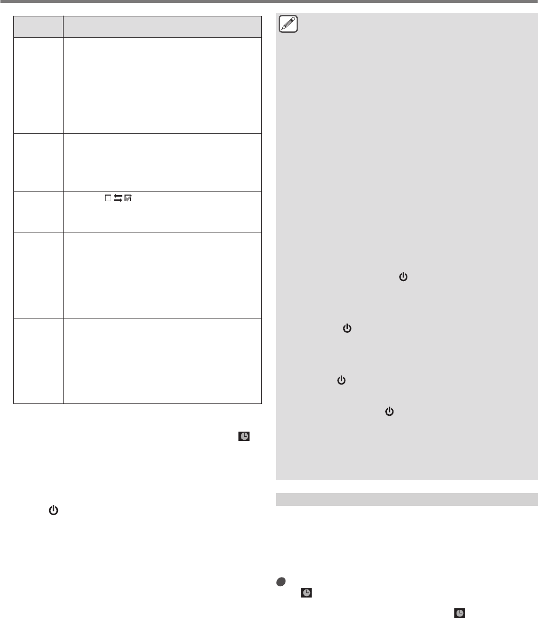
Setting
Item Configuration Method
Timer Mode
Press F4 [MODE] to select a timer operation.
•Power-on: Turns on this transceiver at the
preconfigured time.
•Power-off: Turns off this transceiver at the
preconfigured time.
•Power-on/off: Turns on this transceiver for the
preconfigured time.
•Record: Performs recording for the preconfigured
time.
•Off: Disables timer function.
Repeat
Press F4 [ON/OFF] to toggle the repeat mode between
ON and OFF.
•On: Operates the timer at the preconfigured days
every week.
•Off: Operates the timer only once at the
preconfigured day.
Day of the
Week
Press F4 [] to program the timer operation on
a specific day of the week.
•Timer operation is enabled only on the days for
which the corresponding checkbox is selected.
Power-on
Time/
Power-off
Time
Press F4 [–]/ F5 [+] or the numeric keypad, or turn the
[MULTI/CH] control to configure the time for turning on
and off this transceiver using the timer.
•Configure the time to a value between “00:00” and
“23:59”.
•When “Power-on” is selected, the power-on time
can be configured.
•When “Power-off” is selected, the power-off time
can be configured.
Frequency/
Mode
Press F5 [COPY] to configure the frequency and mode
to start up in by the timer.
•Turn the Tuning or [MULTI/CH] control or use the
Band or Mode key to change the current receiving
VFO or memory channel and align it with the
frequency/mode for performing reception when the
program timer is activated.
•Press F5 [COPY] every time when changing the
frequency or mode to start up by the timer.
5Press F6 [OK].
The “configuration complete” screen appears.
•The programmed timer operation is now enabled. (<< >>
lights up.)
6Press F6 [OK].
Returns to the Timer menu screen.
7Press [ESC] to end the process.
8If the timer (excluding Power-off timer) is set to ON,
press [ ] to power off this transceiver.
•If a timer mode other than “Off” is configured, the [POWER]
LED lights up in orange.
●Before pressing F5 [COPY] to copy the operating data
that is registered in the memory channel, press [M>V] to
shift the operating data of the memory channel to VFO.
●Configure settings other than frequency and mode
before pressing F5 [COPY] in step 5.
●When programming the timer recording function, there
must be an interval of at least 1 minute from the time
recording starts (Power-on time) to the time recording
ends (Power-off time). Otherwise, programmed
recording cannot be performed.
●Timer recording up to a duration of 4 hours can be
configured.
●Program timer can be configured even when F6 [OK] in
step 4 is pressed after the preconfigured interval has
elapsed.
●To record audio to a USB flash drive, insert the USB flash
drive into the (USB-A) connector on the front panel after
configuring the timer recording settings and before
recording starts. Use a USB flash drive that is formatted
by this transceiver and one with sufficient remaining
space.
●Timer recording does not starts unless this transceiver
is powered off.
●When the power of this transceiver is OFF, the [POWER]
LED starts blinking 1 minute before timer recording
starts, and pressing [ ] in this state does not power on
this transceiver.
●If the power of this transceiver is not in the OFF state
when timer recording is ON, a message will be displayed
3 minutes and 1 minute before timer recording starts.
Press [ ] to power off this transceiver.
●The [POWER] LED light remains orange during timer
recording, while the [REC] LED lights up in red.
●To cancel timer recording after the [POWER] LED starts
blinking and before timer recording starts, press and
hold [ ] for 4 seconds.
●While timer recording is in progress, all other operations
are disabled until timer recording stops. To cancel timer
recording, press [ ] and follow the displayed message
to press and hold down F4 [(BREAK)] .
●If the sleep timer is configured, the operation of the
program timer function will be temporarily disabled.
●If the power-off time configured in APO is earlier, the
power of the transceiver is turned off by the APO
function.
Pausing Program Timer Operation
The program timer can be paused while the timer is running.
•Power shutdown at the Power-off time
•Start of timer recording
•Power shutdown by the sleep timer
After the program timer is paused, pressing F [TIMER] resumes
the program timer operation.
Press F [TIMER].
<< >> goes off, and countdown by the sleep timer or
program timer is paused.
Pressing F [TIMER] again illuminates << >> and resumes
countdown by the sleep timer or program timer.
14 CLOCK DISPLAY/TIMER
14-4
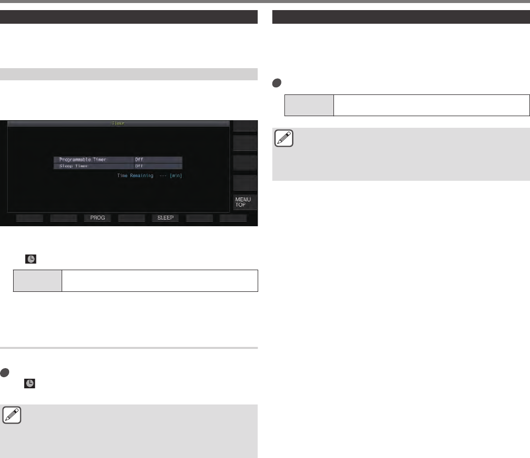
Sleep timer
Sleep timer is a function for powering off this transceiver after the
preconfigured interval has elapsed.
Configuring the Sleep Timer
1Press F [TIMER] on the menu screen to display the
Timer configuration screen.
.
2Press F5 [SLEEP] and select the duration before
powering off this transceiver.
<< >> lights up.
Setting
Value Off (default)/ 5/ 10/ 15/ 30/ 60/ 90/ 120 [min]
•Select “Off” if the sleep timer is not used.
3Press [ESC] to end the process.
Pausing the Sleep Timer
The sleep timer can be paused while the timer is running.
Press F [TIMER].
<< >> goes off, and automatic power-off by the sleep timer
is temporarily disabled.
●Pressing F [TIMER] again disables or resumes both the
sleep timer and programmable timer.
●If the power-off time configured in APO is earlier, the
power of the transceiver is turned off by the APO
function.
APO (Automatic Power Off)
APO is a function that powers off this transceiver when there is no
key or control operation in the RX mode for the preconfigured time
interval. “CHECK” is output in the Morse code from the speaker 1
minute before the power of this transceiver turns off.
Configure in Menu [0-32] “Automatic Power Off”
Setting
Value Off (default)/ 60/ 120/ 180 [min]
●Upon reaching the preconfigured APO time, a timer
power off screen is displayed and the power shuts down
after 10 seconds. Operating any of the keys while the
timer power off screen is displayed turns off the APO
setting.
CLOCK DISPLAY/TIMER 14
14-5

.
14-6