JVC KENWOOD 512000 Scanning Receiver User Manual 1
JVC KENWOOD Corporation Scanning Receiver Users Manual 1
Contents
- 1. Users Manual 1
- 2. Users Manual 2
- 3. Users Manual 3
- 4. Users Manual 4
Users Manual 1

.
TS-890S
INSTRUCTION MANUAL
.
.
B5A-2215-00 (K, E)

Thank You
Thank you for choosing this KENWOOD TS-890S transceiver.
FEATURES
●A high-end and practical transceiver with basic reception
performance that exceeds its class, with multiple functions and
with a feel of TS-990
●Incorporates a 7" TFT color display for comfortable centralized
control of operations using various information: auto scroll
mode, filter scope, TX bar meter, etc.
●Top-class basic reception performance
Provides third-order intermodulation DR: 110 dB, RMDR: 112
dB and BDR**: 150 dB (Measurement example at 2 kHz
detuning: RX frequency 14.2 MHz, MODE CW, BW 500 Hz,
PRE AMP OFF)
*RMDR (Reciprocal Mixing Dynamic Range), **BDR (Blocking
Dynamic Range)
●HF band +50 MHz
●100 W heavy duty output power (50 W for TS-890D)
●Built-in automatic antenna tuner (relay system, high speed
matching)
●SSB, CW, FSK (RTTY), PSK31 (BPSK/QPSK), PSK63 (BPSK),
AM, FM
●Capable of FSK, PSK31/63 as well as CW decoding/encoding
●Equipped with two 32-bit floating-point arithmetic DSPs for
transmission and reception and scope display
●Equipped with LAN, USB and COM ports
●External display connection (via DVI-I connector)
●Capable of remote control operation (direct IP connection)
without using a host PC. Radio Control Program (ARCP-890)
and Radio Host Program (ARHP-890) are also provided free as
before
●Supports USB audio. The speaker and the microphone of a PC
can be used during the USB audio operation by using ARUA-10
(Freeware)
Supplied Accessories
The following accessories are supplied with the transceiver. After
carefully unpacking the transceiver, identify the accessories listed
in the table.
Item Quantity
K-type E-type
DC power cable 1 1
7-pin DIN plug
(For REMOTE connector) 1 1
13-pin DIN plug
(For ACC2 connector) 1 1
Fuse 4 A 1 1
Fuse 25 A 1 1
Instruction Manual
English 1 1
French 1 1
Spanish – 1
Italian – 1
German – 1
Dutch – 1
Schematic diagram 3 3
Warranty Card 1 1
●We recommend you keep the box and packing materials
in case you need to repack the transceiver in the future.
●Do not put the plastic bag used for packing of this
equipment on the place which reaches a small child’s
hand. It will become a cause of suffocation if it wears
flatly.
Market Codes
K-type: :The Americas
E-type: :Europe
The market code is shown on the carton box.
Refer to the specifications for information on the available
operating frequencies.
Copyrights for This Manual
●JVC KENWOOD Corporation shall own all copyrights and other
intellectual properties for the product and the software and for
all manuals and documents attached to the product and the
software.
●A user is required to obtain approval from JVC KENWOOD
corporation, in writing, prior to redistributing this document on
a personal web page or via packet communication.
●A user is prohibited from assigning, renting, leasing or reselling
the document.
●JVC KENWOOD Corporation does not warrant that quality and
functions described in this manual comply with each user’s
purpose of use and, unless specifically described in this
manual, JVC KENWOOD Corporation shall be free from any
responsibility for any defects and indemnities for any damages
or losses.
Software Copyrights
The title to and ownership of copyrights for software, including but
not limited to the firmware that may be distributed individually, to
be embedded in KENWOOD product memories, are reserved for
JVC KENWOOD Corporation.
Any modifying, reverse engineering, copying, reproducing or
disclosing on an Internet website of the software is strictly
prohibited.
A user is required to obtain approval from JVC KENWOOD
corporation, in writing, prior to redistributing this manual on a
personal web page or via packet communication.
Furthermore, any reselling, assigning or transferring of the
software is also strictly prohibited without embedding the software
in KENWOOD product memories.
Software License Agreement
Software License Agreement contains the terms and conditions of
use of the software embedded in or used with the transceiver. A
user is entitled to use the software subject to the acceptance and
agreement of this Software License Agreement by the user. Also,
this Software License Agreement stipulates the terms and
conditions of use of this software embedded in or used with the
transceiver, and a user has the right to use the transceiver with the
software embedded subject to the applicable laws and
regulations, the description and defined in this manual and the
warranty card.
The Software License Agreement can be displayed in the menu
below. (Refer to Chapter 3 for operation of menu.)
Advanced menu [24] “Software License Agreement”
BEFORE USING
BEFORE USING
i

Important Notices Concerning the Software
License Agreement
The software embedded in this transceiver consists of a multiple
number of and individual software components. Title to and
ownership of copyrights for each software component is reserved
for JVC KENWOOD Corporation and the respective bona fide
holder.
This product employs the software component in accordance with
the End User License Agreement (hereinafter referred to as the
“EULA”) stipulated by JVC KENWOOD Corporation and/or the
respective bona fide holder.
There is free software stipulated and governed by the “EULA”, and
this, a distribution condition of the software component in the
executable format under the terms and conditions contained in the
GNU General Public License or Lesser General Public License
(hereinafter referred to as the “GPL/LGPL”), requires to make the
source code for the relevant software components available.
Access the URL below for details of the software component
stipulated in the “GPL/LPGL”.
http://www2.jvckenwood.com/gpl/index.html
Important notice about software can be displayed in the menu
below. (Refer to Chapter 3 for operation of menu.)
Advanced menu [25] “Important Notices concerning Free Open
Source”
About the GPL/ LPGL License
The GPL / LGPL license agreement can be displayed in the menu
below. (Refer to Chapter 3 for operation of menu.)
Advanced menu [26] “About Various Software License
Agreements”
This product includes “Ubiquitous QuickBoot™” technology
developed by Ubiquitous Corp.
Ubiquitous QuickBoot™ is a trademark of Ubiquitous Corp.
Copyright © 2018 Ubiquitous Corp. All rights reserved.
.
Copyrights for Recorded Audio
The broadcast content recorded in this transceiver may not be
reused, except for the personal use, without prior consent of the
right holder under the copyright laws.
Trademarks
KENWOOD is a registered trade mark of JVC KENWOOD
Corporation.
All other product names referenced herein are trademarks or
registered trademarks of their respective manufacturers. Marks
such as ™ and Ⓡ are omitted in the text of body.
Indemnity
●JVC KENWOOD Corporation takes all appropriate measures
to ensure all descriptions in this manual are accurate; however,
this manual may still contain typographical errors (“typos”) and
expressions that are misleading. JVC KENWOOD Corporation
is entirely free from any responsibilities arising from any losses
or damages caused by such typos or expressions.
JVC KENWOOD Corporation has the right to change or
improve the product specifications, etc., described in this
manual without prior notice.
JVC KENWOOD Corporation is entirely free from any
responsibilities for any losses or damages caused by such
changes and improvements.
●JVC KENWOOD Corporation is entirely free from any
responsibilities for any failures, damages or losses arising from,
or in connection with, use of the transceiver with or connected
to any external equipment.
●JVC KENWOOD Corporation does not warrant that the quality
and functions described in this manual comply with your
purpose of use and, unless specifically described in this
manual, JVC KENWOOD Corporation shall be free from any
responsibilities for any defects and indemnities for any
damages or losses. Selection and installation of any external
equipment shall be done at your own risk. You are fully
responsible for the use and effects of external equipment.
●JVC KENWOOD Corporation shall be free from any
responsibilities for any incidental losses or damages, such as
missing communications or call opportunities caused by a
failure or performance error of the transceiver.
Your Queries about External Devices or PC
Connected to the Transceiver
JVC KENWOOD Corporation are pleased to answer, within the
scope of corporate efforts we can provide, your queries about your
operation of this transceiver. Please bear in mind that we cannot
answer any and all technical questions regarding methods of
connection to, configuration for and operation of any external
device and PC beyond our knowledge.
Handling Your Important Data
There is always a risk of losing your important data due to
transceiver failure, occurrence of an unforeseen contingency,
erroneous operation or faulty behavior of the transceiver. The data,
such as the operating information, recorded audio, messages,
configuration data, logs, etc., must be backed up as necessary by
yourself and stored in the external storage device such as a USB
flash drive.
BEFORE USING
ii
Precautions
Please observe the following precautions to prevent fire, personal
injury, and transceiver damage:
●Connect the transceiver only to a power source as described in
this manual or as marked on the transceiver itself.
●Route all power cables safely. Ensure the power cables can
neither be stepped upon nor pinched by items placed near or
against the cables. Pay particular attention to locations near AC
receptacles, AC outlet strips, and points of entry to the
transceiver.
●Take care not to drop objects or spill liquid into the transceiver
through enclosure openings. Metal objects, such as hairpins or
needles, inserted into the transceiver may contact voltages
resulting in serious electrical shocks. Never permit children to
insert any objects into the transceiver.
●Do not attempt to defeat methods used for grounding and
electrical polarization in the transceiver, particularly involving
the power input cable.
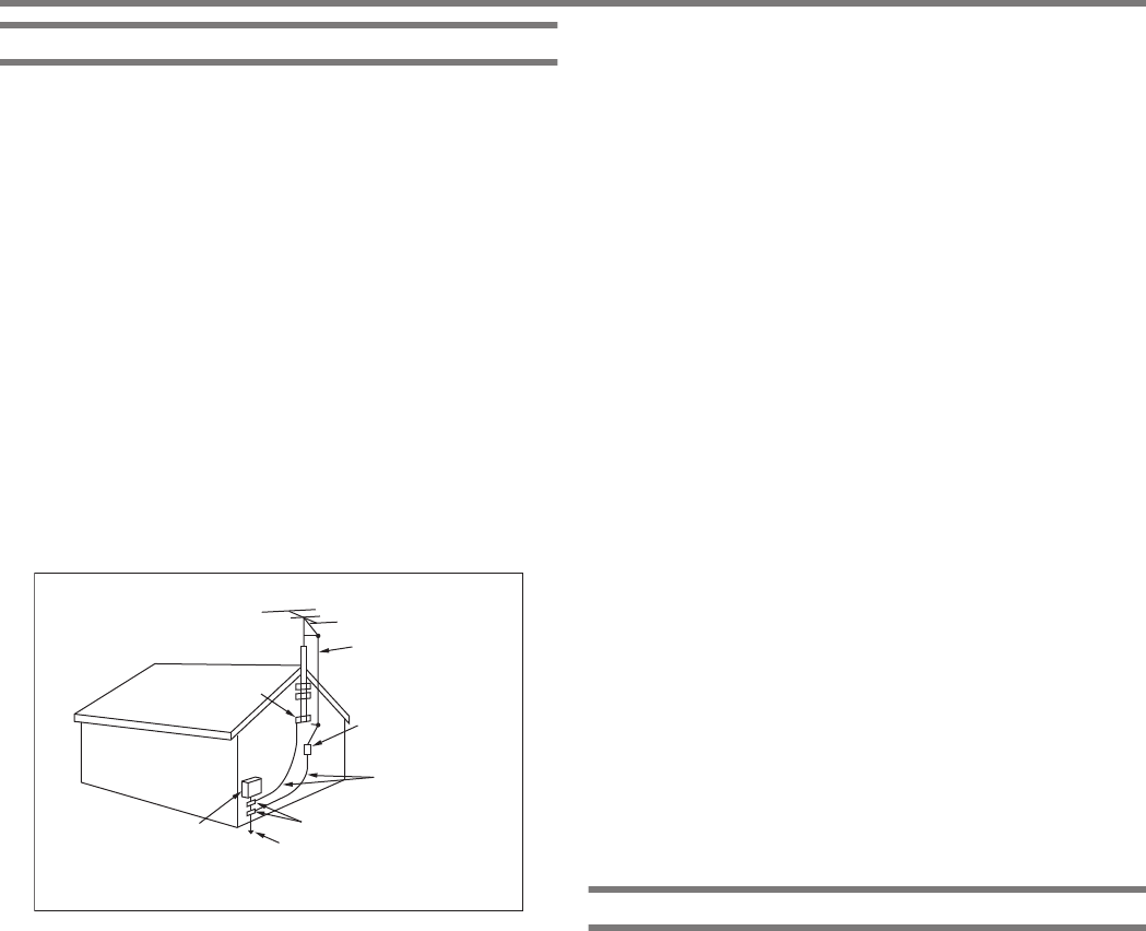
●Adequately ground all outdoor antennas for this transceiver
using approved methods. Grounding helps protect against
voltage surges caused by lightning. It also reduces the chance
of a build‑up of static charge.
.
EXAMPLE OF ANTENNA GROUNDING
ANTENNA
LEAD IN
WIRE
GROUND
CLAMP
ELECTRIC SERVICE
EQUIPMENT
ANTENNA
DISCHARGE UNIT
GROUNDING
CONDUCTORS
GROUND CLAMPS
POWER SERVICE
GROUNDING ELECTRODE
SYSTEM
●Minimum recommended distance for an outdoor antenna from
power lines is one and one‑half times the vertical height of the
associated antenna support structure. This distance allows
adequate clearance from the power lines if the support structure
fails for any reason.
●Locate the transceiver so as not to interfere with its ventilation.
Do not place books or other equipment on the transceiver that
may impede the free movement of air. Allow a minimum of 10
cm (4 inches) between the rear of the transceiver and the wall
or operating desk shelf.
●Do not use the transceiver near water or sources of moisture.
For example, avoid use near a bathtub, sink, swimming pool, or
in a damp basement or attic.
●The presence of an unusual odor or smoke is often a sign of
trouble. Immediately turn the power OFF and remove the power
cable. Contact a KENWOOD service station or your dealer for
advice.
●Locate the transceiver away from heat sources such as a
radiator, stove, amplifier or other devices that produce
substantial amounts of heat.
●Do not use volatile solvents such as alcohol, paint thinner,
gasoline, or benzene to clean the cabinet of the transceiver. Use
only a clean cloth with warm water or a mild detergent.
●Disconnect the input power cable from the power source when
the transceiver is not used for long periods of time.
●Remove the transceiver’s enclosure only to do accessory
installations described in this manual or accessory manuals.
Follow provided instructions carefully, to avoid electrical
shocks. If unfamiliar with this type of work, seek assistance from
an experienced individual, or have a professional technician do
the task.
●Enlist the services of qualified personnel in the following cases:
a) The power supply or plug is damaged.
b) Objects have fallen into or liquid has spilled into the
transceiver.
c) The transceiver has been exposed to rain.
d) The transceiver is operating abnormally or performance has
seriously degraded.
e) The transceiver has been dropped or the enclosure
damaged.
●Do not place the unit in excessively dusty and/or humid areas,
nor on unstable surfaces.
●HF/ 50/ 70 MHz mobile antennas are larger and heavier than
VHF/ UHF antennas. Therefore, use a strong and rigid mount
to safely and securely install the HF/ 50/ 70 MHz mobile
antenna.
●Do not put the plastic bag used for packing of this equipment
on the place which reaches a small child’s hand. It will become
a cause of suffocation if it wears flatly.
●Turn the transceiver power off in the following locations:
In explosive atmospheres (inflammable gas, dust particles,
metallic powders, grain powders, etc.)
About Liquid Crystal Display
●Brightness of the LCD screen may appear uneven depending
on the content displayed. This is not a malfunction.
●The LCD is manufactured using high-density technology to
achieve more than 99.99 % of effective pixels. Less than
0.01 % of the pixels may not be lit or may remain lit all the time.
This is not a malfunction.
●When using this product in a cold region or when the
temperature of this unit or its surroundings is extremely low, it
may take a few minutes for the LCD to reach the normal level
of brightness after turning on the power. This is not a
malfunction. When this occurs, turn off the power and allow the
surrounding environment to reach the ambient temperature
(10 ℃ to 30 ℃ or 32°F to 86°F) before using the unit.
●If you accidentally damaged the LCD display and the liquid in
the LCD display splashes and gets into your eyes or mouth,
rinse thoroughly with water immediately and seek medical
attention. And if the liquid splashes on your clothes or skin, wipe
off immediately with alcohol etc. Leaving it as is will harm your
skin or damage your clothes.
BEFORE USING
iii
Notice to the User
One or more of the following statements may be applicable for this
equipment.
FCC WARNING
This equipment generates or uses radio frequency energy.
Changes or modifications to this equipment may cause harmful
interference unless the modifications are expressly approved
by the party responsible/ JVC KENWOOD. The user could lose
the authority to operate this equipment if an unauthorized
change or modification is made.
INFORMATION TO THE DIGITAL DEVICE USER
REQUIRED BY THE FCC
This equipment has been tested and found to comply with the
limits for a Class B digital device, pursuant to Part 15 of the FCC
Rules. These limits are designed to provide reasonable
protection against harmful interference in a residential
installation.
This equipment generates, uses and can generate radio
frequency energy and, if not installed and used in accordance
with the instructions, may cause harmful interference to radio
communications. However, there is no guarantee that the
interference will not occur in a particular installation. If this
equipment does cause harmful interference to radio or
television reception, which can be determined by turning the
equipment off and on, the user is encouraged to try to correct
the interference by one or more of the following measures:
●Reorient or relocate the receiving antenna.
●Increase the separation between the equipment and
receiver.
●Connect the equipment to an outlet on a circuit different from
that to which the receiver is connected.
●Consult the dealer for technical assistance.
This product is designed for connection to an IT power distribution
system.
Notification
This equipment complies with the essential requirements of
Directive 2014/53/EU.
.
Restrictions
This equipment requires a licence and is intended for use in the
countries below.
AT BE DK FI FR DE GR IS IE
IT LI LU NL NO PT ES SE CH
GB CY CZ EE HU LV LT MT PL
SK SI BG RO HR TR
ISO3166
Information on Disposal of Old Electrical and Electronic
Equipment and Batteries (applicable for countries that have
adopted separate waste collection systems)
Products and batteries with the symbol
(crossed-out wheeled bin) cannot be disposed
as household waste.
Old electrical and electronic equipment and
batteries should be recycled at a facility capable
of handling these items and their waste
byproducts.
Contact your local authority for details in locating
a recycle facility nearest to you.
Proper recycling and waste disposal will help
conserve resources whilst preventing
detrimental effects on our health and the
environment.
Firmware Copyrights
The title to and ownership of copyrights for firmware embedded
in KENWOOD product memories are reserved for
JVC KENWOOD Corporation.
Bu ürün 28300 sayılı Resmi Gazete’de yayımlanan Atik Elektrikli
ve Elektronik Eşyalarin Kontrolü Yönetmeliğe uygun olarak
üretilmiştir.
Eski Elektrikli ve Elektronik Cihazların ve Pillerin İmhası
Hakkında Bilgi (ayrı atık toplama sistemlerine sahip olan
ülkelerde geçerlidir)
Bu sembolü (üzeri çizili çöp bidonu) içeren
ürün ve piller evsel atı k çöpleri ile birlikte
atılamaz.
Kullanılmış elektrikli ve elektronik cihaz ve
piller, bu tür maddeleri ve bunların yan
ürünlerini iş lemeye elverişli bir geri kazanım
tesisine gönderilmelidir.
Size en yakın geri kazanım tesisinin
konumunu öğrenmek üzere yerel
yetkililerinize danışın.
Doğru geri kazanım ve atık uzaklaştırma y
öntemleri, sadece öz kaynakların korunmasına
yardımcı olmakla kalmayıp ayrıca sağlığımıza
ve çevreye olacak zararlı etkilerini engellemeye
yardımcı olur.
This device complies with Industry Canada license exempt RSS
standard(s). Operation is subject to the following two conditions :
(1) this device may not cause interference, and (2) this device must
accept any interference, including interference that may cause
undesired operation of the device.
BEFORE USING
iv

BEFORE USING
CONTENTS
1 INSTALLATION AND CONNECTION
Installation .......................................................................................... 1-1
Antenna Installation and Connection .............................................. 1-1
Ground Connection ......................................................................... 1-1
Installation of Lightning Arrestors .................................................... 1-1
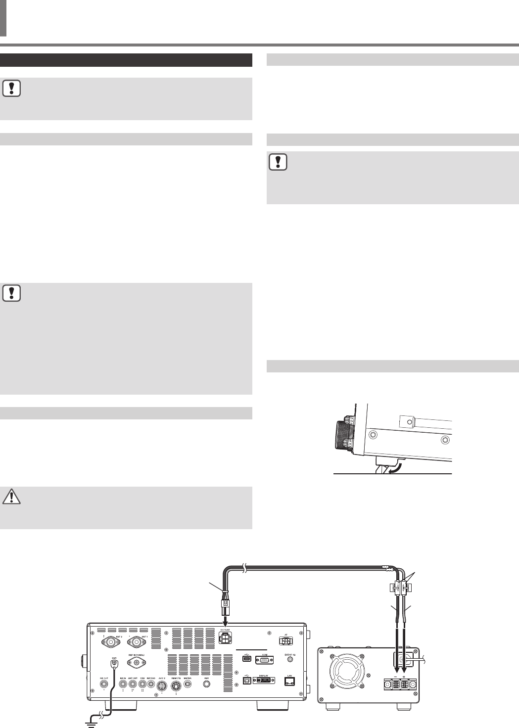
Connection of Regulated DC Power Supply ................................... 1-1
Using the Auxiliary Support ............................................................. 1-1
Torque Adjustment with Tuning Control .............................................. 1-2
Connection of Accessories (Front Panel) ........................................... 1-2
Connection of Accessories (Rear Panel) ............................................ 1-3
Connection with Data Communication Equipment .............................. 1-4
PC Connection ................................................................................ 1-4
TNC Connection ............................................................................. 1-4
Terminal Descriptions ......................................................................... 1-5
2 NAMES AND FUNCTIONS OF PARTS
Front Panel ......................................................................................... 2-1
Panel Key Behavior ......................................................................... 2-1
List of Function Key Behaviors (Standard Mode Screen) ................ 2-4
Rear Panel .......................................................................................... 2-7
Microphone (Optional) ........................................................................ 2-8
Screen ................................................................................................ 2-9
3 MENU
Menu Operation .................................................................................. 3-1
Calling Up a Menu ........................................................................... 3-1
Calling Up a Sub-Menu ................................................................... 3-1
Advanced Menu .......................................................................... 3-1
Common Menu Screen Operations ................................................. 3-2
Exiting the Menu .......................................................................... 3-2
Switching between the CONFIG A and CONFIG B Operating
Environments .................................................................................. 3-2
Menu Items ..................................................................................... 3-3
4 BASIC OPERATIONS
Turning ON/OFF the Power ................................................................ 4-1
Screen Display Settings ..................................................................... 4-1
Changing the Background Color ..................................................... 4-1
Changing the Type of Function Key Display ................................... 4-1
Changing the Frequency Display Font Type ................................... 4-1
Dimmer ............................................................................................... 4-2
Switching the Brightness Level ....................................................... 4-2
Adjusting the Dimmer Level ............................................................ 4-2
Adjusting AF Gain ............................................................................... 4-2
Adjusting RF Gain ............................................................................... 4-2
Adjusting the Squelch Level ............................................................... 4-2
Selecting VFO A/ B ............................................................................. 4-2
Selecting an Operating Band .............................................................. 4-3
Changing the Number of Band Memories ....................................... 4-3
Selecting an Operating Mode ............................................................. 4-4
SSB (LSB-USB) Mode .................................................................... 4-4
CW/ CW-R Mode ............................................................................ 4-4
FSK/ FSK-R/ PSK/ PSK-R Mode .................................................... 4-4
FM/ AM Mode ................................................................................. 4-4
DATA Mode .................................................................................... 4-4
Auto Mode .......................................................................................... 4-4
Turning ON/OFF Auto Mode ........................................................... 4-4
Configuring Auto Mode Frequency Points ....................................... 4-4
Adjustment of Frequencies ................................................................. 4-5
Adjustment Using the Tuning Control .............................................. 4-5
Adjustment Using the Microphone Key ........................................... 4-5
FINE Tuning .................................................................................... 4-5
Configuring the Number of Steps per Revolution of the Tuning Control
......................................................................................................... 4-5
Configuring the Fast Forward Rate of the Tuning Control ............... 4-5
Configuring the Sensitivity for Starting the Fast Forward Operation 4-5
Frequency Adjustment Using the [MULTI/CH] Control .................... 4-6
Rounding the Frequency ............................................................. 4-6
Configuring the Frequency Step Size of the [MULTI/CH] Control 4-6
Switching the AM Broadcast Frequency in 9 kHz Steps .............. 4-6
Adjusting Frequency in MHz Steps ................................................. 4-6
Configuring the Frequency Step Size in MHz .............................. 4-6
Direct Input of Frequency Value ...................................................... 4-6
Frequency Input History .................................................................. 4-7
Frequency Lock .............................................................................. 4-7
Lock Target ................................................................................. 4-7
Transmission ...................................................................................... 4-7
Audio Transmission ........................................................................ 4-7
CW Transmission ............................................................................ 4-7
Adjusting Microphone Gain ............................................................. 4-7
Adjusting TX Output Power ............................................................. 4-8
Fine Adjustment of TX Output Power .............................................. 4-8
TX Output Power Limiter .................................................................... 4-8
Turning ON/OFF TX Output Power Limiter ...................................... 4-8
Configuring the TX Output Power Limiter ........................................ 4-8
Meter .................................................................................................. 4-9
Changing the Meter Type ................................................................ 4-9
Changing the Meter Type from the Menu .................................... 4-9
Changing the Meter Type via Touchscreen Operation ................ 4-9
Switching between TX Meters ........................................................ 4-9
FM Mode S-meter Sensitivity .......................................................... 4-9
Analog Meter Response ................................................................. 4-9
Meter with Peak Hold ...................................................................... 4-9
S Meter Scale ................................................................................. 4-9
TX Meter (Digital) .......................................................................... 4-10
Switching the Antenna ...................................................................... 4-10
RX Antenna ...................................................................................... 4-10
Drive Output (DRV) ........................................................................... 4-10
Turning ON/OFF Drive Output ...................................................... 4-10
Adjusting the Drive Output Level ............................................... 4-10
Built-in Antenna Tuner ...................................................................... 4-11
Impedance Matching with the Antenna ......................................... 4-11
Preset ........................................................................................... 4-11
Holding Transmission at the End of Antenna Tuning .................... 4-11
Switching Antenna Tuner Behavior during Reception ................... 4-12
Configuring the Built-in Antenna Tuner Behavior for Each Band ... 4-12
Connecting the External Antenna Tuner AT-300 ........................... 4-12
5 COMMUNICATING AIDS
Split Operation .................................................................................... 5-1
Direct Input of Frequency Difference Specified by DX Station ........ 5-1
Turning the Tuning Control to Search for a TX Frequency .............. 5-1
⊿F Display ...................................................................................... 5-1
Changing the split frequency using the [RIT/XIT] control ................. 5-1
Configuring the Band Direct Key during Split Operation ................. 5-1
TF-SET (Setting the TX Frequency) ................................................ 5-2
AGC .................................................................................................... 5-2
Switching the AGC Time Constant .................................................. 5-2
Adjusting the AGC Time Constant Preset Value ............................. 5-2
AGC OFF ........................................................................................ 5-3
AGC Quick Recovery ...................................................................... 5-3
RX Equalizer ....................................................................................... 5-4
Turning ON/OFF RX Equalizer ........................................................ 5-4
Selecting an RX Equalizer Characteristic ........................................ 5-4
Adjusting the Equalizer Characteristics ........................................... 5-4
Copying Equalizer Data .................................................................. 5-4
Saving Equalizer Data ..................................................................... 5-5
Reading Equalizer Data .................................................................. 5-5
CONTENTS
CONTENTS
v

Preamplifier ........................................................................................ 5-6
RX Monitor ......................................................................................... 5-6
SWL (BCL) Mode ............................................................................... 5-6
Band Switching in the SWL Mode (VFO Mode) .............................. 5-6
Transmission in Data Mode ................................................................ 5-7
Transmission via PTT Switch, SS Terminal and SEND ................... 5-7
Transmission via DATA PTT or DATA SEND .................................. 5-7
RIT/XIT ............................................................................................... 5-7
RIT (Receiver Incremental Tuning) ................................................. 5-7
RIT Shift ...................................................................................... 5-7
XIT (Transmitter Incremental Tuning) .............................................. 5-7
XIT Shift ....................................................................................... 5-7
Adjusting the Carrier Level ................................................................. 5-8
Operation in CW Mode ....................................................................... 5-8
CW Break-in ................................................................................... 5-8
Turning ON/OFF Break-in ........................................................... 5-8
Adjusting the Break-in Mode and Break-in Delay Time ............... 5-9
Adjusting the Sidetone and Pitch Frequency .................................. 5-9
Adjusting the Sidetone Volume ................................................... 5-9
CW Rise Time ................................................................................. 5-9
Auto Zero-in (CW Auto Tune) ......................................................... 5-9
CW BFO Sideband ......................................................................... 5-9
CW Automatic Transmission from SSB Mode ................................. 5-9
Frequency Offset when Shifting from SSB to CW Mode ............... 5-10
Encoding/Decoding Morse Code ...................................................... 5-10
Displaying the CW Communication Screen .................................. 5-10
Operating the CW Communication Screen ................................ 5-10
Indicator Displays ...................................................................... 5-10
Adjusting the Decode Threshold Level ......................................... 5-11
Decode Filter ................................................................................ 5-11
Transmitting Character Strings via USB Keyboard Operation ....... 5-11
Encoding Character Strings Using the CW Message Memory ...... 5-12
Paddle Operation on CW Communication Screen ........................ 5-12
Paddle Operation when the TX Details Display Area is Empty .. 5-12
Paddle Operation during Encoding of Character Strings in the TX
Details Display Area .................................................................. 5-12
Saving CW Communication Logs ................................................. 5-12
Electronic Keyer ............................................................................... 5-13
Selecting the PADDLE Jack Behavior ........................................... 5-13
Selecting the KEY Jack Behavior .................................................. 5-13
Operation Mode of the Electronic Keyer ....................................... 5-13
Reversing Dot and Dash ............................................................... 5-13
Mic Paddle Mode .......................................................................... 5-13
Adjusting the Keying Speed .......................................................... 5-13
Changing the Weighting ................................................................ 5-14
Weight Ratio Reverse ............................................................... 5-14
CW Message Memory ...................................................................... 5-14
Switching the Method of Registering CW Messages .................... 5-14
Registering CW Messages via Text Input ..................................... 5-14
Registering CW Messages via Paddle Operation ......................... 5-15
Contest Number ............................................................................ 5-15
Configuring the Starting Contest Number (Text Input Only) ....... 5-15
Selecting a Method for Sending out Contest Number (Text Input
Only) .......................................................................................... 5-15
Selecting a Channel for Counting up the Contest Numbers (Text Input
Only) .......................................................................................... 5-16
Decrementing the Contest Number (Text Input Only) ................ 5-16
Playing/Transmitting CW Messages ............................................. 5-16
Repeat Playback of CW Messages ........................................... 5-16
Configuring the Repeat Playback Interval .................................. 5-17
Interrupt Keying ............................................................................. 5-17
Deleting a CW Message ............................................................... 5-17
RTTY Operation ............................................................................... 5-17
Displaying the RTTY Communication Screen ............................... 5-17
Switching between the FFT Scope and X-Y Scope Display ...... 5-17
Operating the RTTY Encode/Decode Screen ........................... 5-18
Indicator Displays ...................................................................... 5-18
Saving RTTY Communication Logs .............................................. 5-18
Adjusting the RTTY Decode Threshold Level ............................... 5-18
FFT Scope/X-Y Scope Display Setting ......................................... 5-18
FFT Scope Waveform Averaging .............................................. 5-18
Selecting a Waterfall Display Type ............................................ 5-19
Tracking Speed/Density Level of X-Y Scope ............................. 5-19
Transmitting Character Strings Using USB Keyboard ................... 5-19
Transmitting the Input Character String Immediately ................. 5-19
Temporarily Placing Character Strings in the TX Details Display Area
before Transmission .................................................................. 5-19
RTTY Message Memory ................................................................... 5-20
Registering RTTY Messages ........................................................ 5-20
Configuring Auto TX/RX for the RTTY Message Memory ............. 5-20
Transmitting Character Strings from the RTTY Message Memory 5-21
Settings Related to RTTY Encode/Decode ................................... 5-21
Enabling Decode UOS (Unshift on Space) ................................ 5-21
Newline Code Setting ................................................................ 5-21
Diddle Operation ....................................................................... 5-21
Encode UOS ............................................................................. 5-21
Sending a Newline Code at the Start or End of a Transmission 5-21
RTTY Parameters ......................................................................... 5-21
Configuring the Mark Frequency ............................................... 5-21
Configuring the RTTY Shift Width .............................................. 5-21
Frequency Reverse in RTTY Mode ........................................... 5-22
Operating RTTY Using an External Device ................................... 5-22
ACC 2 Keying Polarity Setting ................................................... 5-22
Audio Peak Filter ....................................................................... 5-22
PSK Operation .................................................................................. 5-22
Displaying the PSK Communication Screen ................................. 5-22
Switching between the FFT Scope and Vectorscope Display ... 5-22
Operating the PSK Communication Screen .............................. 5-23
Indicator Displays ...................................................................... 5-23
Saving PSK Communication Logs ................................................ 5-23
Adjusting the PSK Decode Threshold Level ................................. 5-23
FFT Scope/Vectorscope Display Setting ...................................... 5-24
FFT Scope Waveform Averaging .............................................. 5-24
Selecting a Waterfall Display Type ............................................ 5-24
Vectorscope .............................................................................. 5-24
AFC (Automatic Frequency Control) ............................................. 5-24
Configuring the AFC Tuning Range ........................................... 5-24
NET ........................................................................................... 5-24
Switching between BPSK and QPSK ............................................ 5-24
Switching between PSK31 and PSK63 ......................................... 5-25
Transmitting Character Strings from USB Keyboard ..................... 5-25
Transmitting the Input Character String Immediately ................. 5-25
Temporarily Placing Character Strings in the Character String Buffer
before Transmission .................................................................. 5-25
PSK Message Memory ..................................................................... 5-26
Registering Messages .................................................................. 5-26
Configuring Auto TX/RX for the PSK Message Memory ............... 5-26
Transmitting Character Strings from the PSK Message Memory .. 5-27
Settings Related to PSK ................................................................ 5-27
Configuring the PSK Tone Frequency ....................................... 5-27
Reversing the Direction of Phase Change in the QPSK Mode .. 5-27
PSK Operation Using a PC ........................................................ 5-27
Communication Log ......................................................................... 5-27
Selecting a Log File Format .......................................................... 5-27
Displaying a Time Stamp .............................................................. 5-28
Selecting a Time Stamp Type ................................................... 5-28
Selecting a Clock Type .............................................................. 5-28
Editing the Communication Log File .............................................. 5-28
Operation in FM Mode ...................................................................... 5-28
Adjusting Microphone Gain during Operation in FM Mode ........... 5-28
Operation in Narrow FM Mode ...................................................... 5-29
Operating the FM Repeater .......................................................... 5-29
Configuring the Tone Signal .......................................................... 5-29
Selecting a Tone ....................................................................... 5-29
CONTENTS
vi

Configuring the Tone Frequency ............................................... 5-29
Tone Frequency Scan ............................................................... 5-29
CTCSS Operation ......................................................................... 5-30
Selecting CTCSS ...................................................................... 5-30
Configuring the CTCSS Frequency ........................................... 5-30
CTCSS Frequency Scan ........................................................... 5-30
Cross Tone ................................................................................... 5-30
Selecting Cross Tone ................................................................ 5-30
Configuring the TX/RX Tones .................................................... 5-30
6 REJECTING INTERFERENCE
Attenuator ........................................................................................... 6-1
Switching the IF Filter Band Characteristics ....................................... 6-1
Switching the RX Filter (A, B, C) ..................................................... 6-1
Configuring the Selectable Types of RX Filters ........................... 6-1
Filter Scope ..................................................................................... 6-1
RX Filter Screen ................................................................................. 6-2
Displaying the RX Filter Screen ...................................................... 6-2
Selecting a Roofing Filter ................................................................ 6-2
Switching the IF Filter Shape .......................................................... 6-2
Switching the AF Filter Type ........................................................... 6-2
Configuring the Behavior of the HI/SHIFT and LO/WIDTH Controls
(SSB/SSB-DATA Only) ................................................................... 6-2
Changing the Cutoff Frequency ...................................................... 6-3
Changing the Passband Width and Shift Amount ........................... 6-3
Preset Passband Characteristics .................................................... 6-4
Audio Peak Filter in the CW Mode ...................................................... 6-4
Turning ON/OFF Audio Peak Filter ................................................. 6-4
Displaying the Audio Peak Filter Screen ......................................... 6-4
Switching the Passband Characteristics ......................................... 6-4
Shifting the Passband Width ........................................................... 6-4
Configuring the Peak Gain .............................................................. 6-4
Audio Peak Filter in the FSK Mode ..................................................... 6-5
Noise Blanker ..................................................................................... 6-5
Turning ON/OFF Noise Blanker 1/2 ................................................ 6-5
Adjusting the NB1 Level .................................................................. 6-5
NB2 ................................................................................................. 6-6
Configuring the NB2 Effect Level (Type A)/ NB2 Pulse Sensitivity
Level (Type B) ............................................................................. 6-6
Configuring the Blanking Duration (Type B Only) ........................ 6-6
Configuring the NB2 Attenuation Level (Type B Only) ................. 6-6
Notch Filter ......................................................................................... 6-6
Turning ON/OFF Notch Filter .......................................................... 6-6
Switching the Notch Filter Bandwidth .............................................. 6-7
Noise Reduction ................................................................................. 6-7
Turning ON/OFF Noise Reduction .................................................. 6-7
Configuring the NR1 Effect Level .................................................... 6-7
Configuring the NR2 Correlation Time ............................................ 6-7
Beat Canceler ..................................................................................... 6-8
Turning ON/OFF Beat Canceler ...................................................... 6-8
DSP Monitor ....................................................................................... 6-8
Assigning DSP Monitor to PF Key ................................................... 6-8
Expanding the Passband Width Using DSP Monitor ....................... 6-8
7 SCOPE FUNCTIONS
Bandscope ......................................................................................... 7-1
Displaying the Bandscope .............................................................. 7-1
Switching the Bandscope Display Type ...................................... 7-1
Adjusting the Reference Level ........................................................ 7-1
Configuring the Speed of Waterfall Drop ......................................... 7-1
Waterfall Display during Tuning (Center Mode) .............................. 7-2
Reduced Bandscope Display .......................................................... 7-2
Switching the Scope Display Mode ................................................. 7-2
Switching the Display Frequency Span ........................................... 7-2
Selecting Relative or Absolute Frequency Display for the Grid (Center
Mode) ............................................................................................. 7-2
Marker Shift ..................................................................................... 7-2
Shifting the Marker ...................................................................... 7-2
Changing the Shift Position of Marker Shift ................................. 7-3
Expand ............................................................................................ 7-3
Scope Range of Each Band (Fixed Mode) ...................................... 7-3
Switching the Scope Range ........................................................ 7-3
Configuring the Scope Range ..................................................... 7-3
Marker Centering ............................................................................ 7-4
Notification on Exceeding of Lower or Upper Limit .......................... 7-4
Displaying Tuning Assist Line (SSB Only) ....................................... 7-4
Touchscreen Tuning ....................................................................... 7-4
Turning ON/OFF Touchscreen Tuning ........................................ 7-4
Configuring the Gradation of the Waterfall ................................... 7-4
Touchscreen Tuning Correction .................................................. 7-5
Step Correction ........................................................................... 7-5
Marker Display ................................................................................ 7-5
Registering a Marker ................................................................... 7-5
Deleting a Registered Frequency ................................................ 7-5
Turning ON/OFF Marker Function ............................................... 7-5
Displaying the Maximum Value in the Waveform ............................ 7-5
Turning ON/OFF Maximum Value Display ................................... 7-5
Configuring the Hold Type ........................................................... 7-5
Pausing the Waveform Display ....................................................... 7-6
Averaging of Bandscope Waveform ............................................... 7-6
Switching the Bandscope Attenuator .............................................. 7-6
Displaying the TX Signal Waveform ................................................ 7-6
Audio Scope ....................................................................................... 7-6
Displaying the Audio Scope ............................................................ 7-6
Switching the Audio Scope Display Type .................................... 7-6
Switching the Audio Scope Attenuator ............................................ 7-7
Switching the Display Frequency Span of the Audio Scope ............ 7-7
Switching the Oscilloscope Level .................................................... 7-7
Switching the Sweep Time .............................................................. 7-7
Pausing the Audio Scope ................................................................ 7-7
8 TRANSMIT FUNCTIONS
Configuration of the Input Path of TX Audio ........................................ 8-1
Switching the Audio Source Input ................................................... 8-1
VOX (Voice-Operated Transmit) ......................................................... 8-1
Turing ON/OFF VOX Function ........................................................ 8-1
Selecting Audio Source Input for Data VOX .................................... 8-1
VOX Configuration Screen .............................................................. 8-2
Adjusting VOX Gain .................................................................... 8-2
Adjusting the Anti VOX Gain Level .............................................. 8-2
Adjusting VOX Delay Time .......................................................... 8-2
VOX Voice Delay ............................................................................ 8-2
TX Monitor .......................................................................................... 8-3
Adjusting the TX Monitor Level ....................................................... 8-3
Speech Processor .............................................................................. 8-3
Turning ON/OFF Speech Processor ............................................... 8-3
Speech Processor Configuration Screen ........................................ 8-3
Configuring the Speech Processor Input Level ............................ 8-4
Configuring the Speech Processor Output Level ......................... 8-4
Configuring the Speech Processor Effect .................................... 8-4
TX Filter .............................................................................................. 8-4
Displaying the Filter Scope during Transmission ............................ 8-4
Changing the TX Filter Bandwidth ................................................... 8-5
Configuring the Low Cutoff Frequency in the SSB/AM Mode ...... 8-5
Configuring the High Cutoff Frequency in the SSB/AM Mode ..... 8-5
Configuring the Low Cutoff Frequency in the SSB-DATA/AM-DATA
Mode ........................................................................................... 8-5
Configuring the High Cutoff Frequency in the SSB-DATA/AM-DATA
Mode ........................................................................................... 8-5
TX Equalizer ....................................................................................... 8-5
Turning ON/OFF TX Equalizer ........................................................ 8-5
Selecting a Frequency Characteristic for the TX Equalizer ............. 8-5
CONTENTS
vii

Adjusting the TX Equalizer .............................................................. 8-6
Copying the TX Equalizer Settings .................................................. 8-6
Saving the TX Equalizer Settings .................................................... 8-6
Reading the TX Equalizer Settings ................................................. 8-7
TX Tuning ........................................................................................... 8-7
Adjusting TX Output Power during TX Tuning ................................. 8-7
Timeout Timer (TOT) .......................................................................... 8-8
ID Beep .............................................................................................. 8-8
9 MEMORY CHANNELS
Displaying the Memory Channel List .................................................. 9-1
Registering Operating Frequency Data to a Memory Channel ........ 9-2
Configuring the Operating Data through Direct Frequency Entry .... 9-2
Memory Channel Mode ...................................................................... 9-2
Operating in the Memory Channel Mode ........................................ 9-2
Direct Entry of a Memory Channel Number ................................. 9-2
Changing the Memory Channel Temporarily ................................... 9-3
Changing the Frequency Temporarily ......................................... 9-3
Copying the Operating Data of a Memory Channel ............................ 9-3
Memory Shift (Memory → VFO) ....................................................... 9-3
Selecting a Memory Channel and Copying to VFO ..................... 9-3
Copying Data from the Memory Channel List Screen to VFO ...... 9-3
Channel-to-Channel Copying .......................................................... 9-3
Configuring the Program Scan Frequency Range .............................. 9-4
Erasing Memory Channels ................................................................. 9-4
Registering a Memory Channel Name ................................................ 9-4
Quick Memory Channels .................................................................... 9-5
Registering a Quick Memory Channel ............................................. 9-5
Calling up a Quick Memory Channel ............................................... 9-5
Configuring the Number of Quick Memory Channels ...................... 9-5
Erasing a Quick Memory Channel ................................................... 9-5
Memory Shift (Quick Memory → VFO) ............................................. 9-6
10 SCAN
Program Scan ................................................................................... 10-1
Starting the Program Scan (VFO Scan) ........................................ 10-1
Configuring the Program Scan (VFO Scan) Frequency Range ..... 10-1
Switching the Scan Speed ............................................................ 10-2
Program Slow Scan ...................................................................... 10-2
Turning ON/OFF Program Slow Scan ....................................... 10-2
Configuring the Frequency Points for Program Slow Scan ........ 10-2
Configuring the Segment for Program Slow Scan ..................... 10-3
Scan Hold ..................................................................................... 10-3
Memory Scan ................................................................................... 10-3
Performing Memory Scan ............................................................. 10-3
Configuring All-channel Scan and Group Scan ............................. 10-3
Memory Channel Lockout ............................................................. 10-4
Quick Memory Scan ......................................................................... 10-4
Configuring the Conditions for Resuming Scan ................................ 10-4
11 USB/FILE MANAGEMENT
Managing Different File Types .......................................................... 11-1
USB/File Management Menu Screen ............................................... 11-2
Configuring the Destination for Saving Files ................................. 11-2
Saving Settings Data ..................................................................... 11-2
Reading Settings Data .................................................................. 11-3
Changing the Name of Files Stored in the Built-in Memory ........... 11-4
Copying Files to a PC .................................................................... 11-4
Deleting Files (Built-in Memory) .................................................... 11-5
Formatting a USB Flash Drive ....................................................... 11-5
Copying Files to a USB Flash Drive .............................................. 11-5
Safely Removing the USB Flash Drive .......................................... 11-6
12 VOICE MESSAGE/AUDIO FILE
Recording/Playing a Voice Message ................................................ 12-1
Recording a Voice Message ......................................................... 12-1
Registering a Name for a Voice Message ..................................... 12-1
Playing Back a Voice Message ..................................................... 12-2
Adjusting the Playback Volume ..................................................... 12-2
Sending a Voice Message ............................................................ 12-2
Deleting a Voice Message ............................................................ 12-2
Configuring the Time Interval for Repeated Transmission ............ 12-2
Recording/Playing Voice Communication ........................................ 12-3
Manual Recording ......................................................................... 12-3
Full-time Recording ....................................................................... 12-3
Configuring the Maximum Duration for Full-time Recording ...... 12-3
Saving Full-time Recording Audio ............................................. 12-3
Audio Recording in Tandem with Squelch .................................... 12-3
Quick Playback ................................................................................. 12-4
Adjusting the Playback Volume ..................................................... 12-4
Audio Recording File Screen ............................................................ 12-4
Playing Back an Audio File ............................................................ 12-4
Renaming an Audio File ................................................................ 12-5
Deleting an Audio File ................................................................... 12-5
13 VOICE GUIDANCE
Voice Guidance ................................................................................ 13-1
Adjusting the Voice Guidance Volume .......................................... 13-1
Adjusting the Voice Guidance Speed ............................................ 13-1
Configuring the Voice Guidance Language ................................... 13-1
Auto Voice Guidance .................................................................... 13-1
Voice 1 ...................................................................................... 13-2
Voice 2 .................................................................................... 13-12
Voice 3 .................................................................................... 13-12
14 CLOCK DISPLAY/TIMER
Configuring Date and Time ............................................................... 14-1
Displaying the Clock Menu Screen ............................................... 14-1
Configuring the Local Clock Date .............................................. 14-1
Configuring the Local Clock Time .............................................. 14-1
Configuring the Local Clock Time Zone ..................................... 14-1
Configuring the Auxiliary Clock Time Zone ................................ 14-1
Registering an Auxiliary Clock Identifier .................................... 14-1
Configuring the Date Display Format ......................................... 14-2
Configuring the Clock Display ................................................... 14-2
Clock Correction Using NTP (Network Time Protocol) ..................... 14-2
Displaying the Auto Correction Configuration Screen ................... 14-2
Configuring the NTP Server Address ........................................ 14-2
Turning ON/OFF Auto Clock Correction .................................... 14-3
Correcting the Date and Time Manually .................................... 14-3
Timer ................................................................................................ 14-3
Configuring the Program Timer ..................................................... 14-3
Pausing Program Timer Operation ................................................ 14-4
Sleep timer ....................................................................................... 14-5
Configuring the Sleep Timer ......................................................... 14-5
Pausing the Sleep Timer ........................................................... 14-5
APO (Automatic Power Off) .............................................................. 14-5
15 NETWORK/KNS OPERATION
LAN .................................................................................................. 15-1
Configuring the IP Address ........................................................... 15-1
Viewing the MAC Address ............................................................ 15-2
KNS Operation ................................................................................. 15-2
Configuring for KNS Operation ..................................................... 15-3
LAN Connection Settings .......................................................... 15-3
Administrator Settings ............................................................... 15-3
Built-in VoIP Function ................................................................ 15-4
Audio Input/Output Level of Built-in VoIP ................................... 15-4
Built-in VoIP Jitter Absorption Buffer ......................................... 15-4
Prohibition of Remote Volume Control ...................................... 15-4
KNS Communication Log .......................................................... 15-4
CONTENTS
viii

KNS User Registration .................................................................. 15-5
KNS Users List .......................................................................... 15-5
Registering User Information ..................................................... 15-5
Editing User Information ............................................................ 15-5
Deleting a User .......................................................................... 15-5
Remote Operation by Registered User ......................................... 15-6
Session Time ................................................................................ 15-6
KNS Welcome Message ............................................................... 15-6
16 OTHER FUNCTIONS
Configuring the Power-on Message ................................................. 16-1
Configuring the Screen Saver ........................................................... 16-1
Configuring the Screen Saver Type .............................................. 16-1
Saving Images for Use by Type 3 Screen Saver ....................... 16-1
Configuring the Time for Launching the Screen Saver .................. 16-1
Configuring the Displayed Screen Saver Text ............................... 16-1
Configuring the Long-press Behavior of Keys .................................. 16-2
Configuring the Beep Volume ........................................................... 16-2
PF Keys (Programmable Function Keys) .......................................... 16-2
Assigning Functions to PF Keys (Front Panel) .............................. 16-2
Assigning Functions to PF Keys (Microphone) ............................. 16-2
Assigning Functions to the PF Keys (KEYPAD Jack) .................... 16-3
List of Assignable Functions ......................................................... 16-3
PC Control ........................................................................................ 16-5
Configuring the COM/USB (Rear Panel) Baud Rate ..................... 16-5
Configuring the USB Keyboard ......................................................... 16-5
Sending Message from the USB Keyboard ................................... 16-5
Selecting a USB Keyboard Language ........................................... 16-5
Configuring the Time for Activating Key Repeat ............................ 16-5
Configuring the Key Repeat Speed ............................................... 16-5
Saving a Screen Shot ....................................................................... 16-6
Configuring Output to an External Meter ........................................... 16-6
Configuring the Output Signal Format of the External Meter ......... 16-6
Configuring the External Meter Output Level ................................ 16-6
External Monitor Output .................................................................... 16-7
Configuring the External Monitor Resolution ................................. 16-7
Configuring Audio Input/Output ........................................................ 16-7
Configuring the USB Connector Input/Output Signal .................... 16-7
Configuring the Audio Signal Input Level ................................... 16-7
Configuring the Audio Signal Output Level ................................ 16-7
Configuring the ACC 2 Connector Input/Output Signal ................. 16-7
Configuring the Audio Signal Input Level ................................... 16-7
Configuring the Audio Signal Output Level ................................ 16-7
Configuring the TX Monitor Level for External Audio Output ......... 16-7
Configuring Audio Mixing for the External Audio Output Connector 16-7
Switching the Reference Signal ........................................................ 16-8
Switching the CTCSS Mute Operation ............................................. 16-8
Configuring the SQL Control Signal .................................................. 16-8
Configuring the Logic of PSQ ........................................................ 16-8
Configuring the PSQ Output Conditions ........................................ 16-8
Switching the COM Connector Signal ........................................... 16-8
Split Transfer .................................................................................... 16-9
Connection .................................................................................... 16-9
Split Transfer 1 .............................................................................. 16-9
Configuration ............................................................................. 16-9
Operation ................................................................................ 16-10
Muting the Sub-receiver .......................................................... 16-10
Split Transfer 2 ............................................................................ 16-10
TX Inhibit ........................................................................................ 16-11
Tuning the Packet Cluster .............................................................. 16-11
Connection .................................................................................. 16-11
Receiving Packet Cluster Data ................................................... 16-11
Control of External Devices ............................................................ 16-12
TX Inhibit in Busy State (when Squelch is Open) ........................ 16-12
Reversing the PKS Signal Polarity .............................................. 16-12
USB Keying ................................................................................ 16-12
Decoded Character Output ......................................................... 16-12
Turning ON/OFF Decoded Character Output .......................... 16-12
Configuring the Baud Rate of the Virtual COM (Enhanced)
Connector ................................................................................ 16-12
Controlling the Linear Amplifier ....................................................... 16-13
Connection .................................................................................. 16-13
TL-922 Connection .................................................................. 16-13
General Linear Amplifier Connection ....................................... 16-13
Linear Amplifier Menu Screen ..................................................... 16-14
Turning ON/OFF Linear Amplifier ............................................ 16-14
Linear Amplifier TX Control ..................................................... 16-14
Turning ON/OFF Linear Amplifier TX Delay ............................ 16-14
Linear Amplifier TX Delay Time ............................................... 16-14
Linear Amplifier Relay Control ................................................. 16-14
External ALC Voltage of Linear Amplifier ................................. 16-14
Operating the Transverter/Exciter ................................................... 16-15
Connecting to a Transverter ........................................................ 16-15
Turning off Power Down during Transverter Operation ............... 16-15
Displaying the Operating Frequency Configured for the Transverter 16-15
Configuring the Operating Frequency of the Transverter ............ 16-15
Antenna Output for External Receivers ........................................... 16-15
Emergency Call (K Type Only) ....................................................... 16-16
Crossband Repeater ...................................................................... 16-16
Connection .................................................................................. 16-16
Operation .................................................................................... 16-16
Sky Command System II ................................................................ 16-17
Sky Command System II Diagram .............................................. 16-17
Preparation ................................................................................. 16-17
Starting Sky Command System II Operation ............................... 16-17
TS-890S + TH-D7A/ TH-D72(A/E)/ TM-D700A/ TM-D710/G(A/E)/
TM-V71A + RC-D710 (Transporter) Setup .............................. 16-17
17 MAINTENANCE AND ADJUSTMENT
Reset ................................................................................................ 17-1
Firmware Update .............................................................................. 17-1
Firmware Version Check ............................................................... 17-1
Calibration of Internal Reference Frequency .................................... 17-2
Adjusting the Touchscreen ............................................................... 17-3
Adjusting the Display Color ............................................................... 17-3
Replacing the Fuse ........................................................................... 17-3
Replacing the Fuse of the External Antenna Tuner ....................... 17-3
Replacing the Fuse of the DC Power Cable .................................. 17-3
18 TROUBLESHOOTING
General Information .......................................................................... 18-1
Service .......................................................................................... 18-1
Service Note ................................................................................. 18-1
Cleaning ........................................................................................ 18-1
Troubleshooting ................................................................................ 18-2
Problems Related to Reception and Transmission ....................... 18-2
Problems Related to Data Communication, PC and Network ....... 18-5
Troubles Related to Recording and Playback ............................... 18-7
Error Messages ............................................................................. 18-8
Warning Messages ..................................................................... 18-10
Internal Beats ................................................................................. 18-11
Spurious Signals on the Bandscope ............................................... 18-11
19 OTHERS
Optional Accessories ........................................................................ 19-1
Installing the YG-82CN-1 Roofing Filter ........................................ 19-1
Specifications ................................................................................... 19-2
CONTENTS
ix

.
x
Installation
●Do not lift this transceiver by holding the Tuning control
or other control knobs on the front panel or the
connectors on the rear panel. Doing so may result in
injury or damage of the control knobs.
Antenna Installation and Connection
The antenna system is made up of the antenna, coaxial cables and
a ground terminal. Installing the antenna system carefully and
properly helps to optimize the performance of the transceiver.
•Make use of a correctly-adjusted 50 Ω antenna, 50 Ω coaxial
cables and appropriate connectors. Make sure that all
connections are cleaned and free of dirt before fastening them.
•Match the impedance of the coaxial cable and antenna such
that SWR is 1:1.5 or lower.
•A high SWR may lower the TX output power, thereby causing
radio interference with electrical appliances such as radio and
TV as well as failure of this transceiver.
•If reports on signal distortion are received, this means the
transceiver may not be transmitting efficiently.
●Transmitting without connecting the antenna may
damage this transceiver. Before transmission, connect
an antenna or a 50 Ω dummy load to this transceiver.
●The protection circuit of this transceiver will be activated
if the SWR of the antenna exceeds 1.5. Use an antenna
with a low SWR.
●When an RX antenna that makes use of semiconductors
(such as an active antenna) is connected, transmission
or antenna tuning must not be performed. Doing so
supplies power to the antenna and may damage the
semiconductor circuit of the antenna.
Ground Connection
Connect to the ground terminal correctly to avoid risks such as
electric shock.
First of all, bury one or multiple ground bars or a large copper sheet
in the ground and connect them to the GND terminal of this
transceiver. Use a thick conducting wire or a cut copper band that
is as short as possible for this connection.
●Gas pipes, conduit pipes for power distribution, plastic
water pipes and the like must not be used for grounding.
Not only are they ineffective for grounding, they may also
result in accidents or fire.
Installation of Lightning Arrestors
•To prevent fire, electric shock, malfunctioning and injury due to
lightning, install a coaxial lightning arrestor.
•Besides installing a coaxial lightning arrestor, disconnect the
cable of the antenna from this transceiver if lightning is
anticipated.
Connection of Regulated DC Power Supply
●Make sure to turn off the power of the regulated DC
power supply before connecting the DC power cord.
●Do not insert the power plug of the regulated DC power
supply into the AC outlet until all the connections are
complete.
A DC 13.8 V regulated DC power supply is needed for using this
transceiver. It cannot be connected directly to an AC outlet. Use
the supplied DC power cord to connect this transceiver to the
regulated DC power supply.
•The current capacity needed for the regulated DC power supply
is 22.5 A and above. Use one with sufficient current capacity.
1Connect the DC power cord to the regulated DC
power supply.
Connect the red wire to the “+” terminal and the black wire to
the “-” terminal.
2Next, connect the DC power cord to the DC 13.8 V
power connector of this transceiver.
Insert the cord fully into the power connector.
Using the Auxiliary Support
An auxiliary support is stored inside the front leg of this transceiver.
Pull it toward you if you want the panel to face slightly upwards.
.
.
DC Power Cord
Rear Side of This Transceiver Regulated DC Power Supply
Red (+)
Black (–)
Fuse
INSTALLATION AND CONNECTION 1
1 INSTALLATION AND CONNECTION
1-1
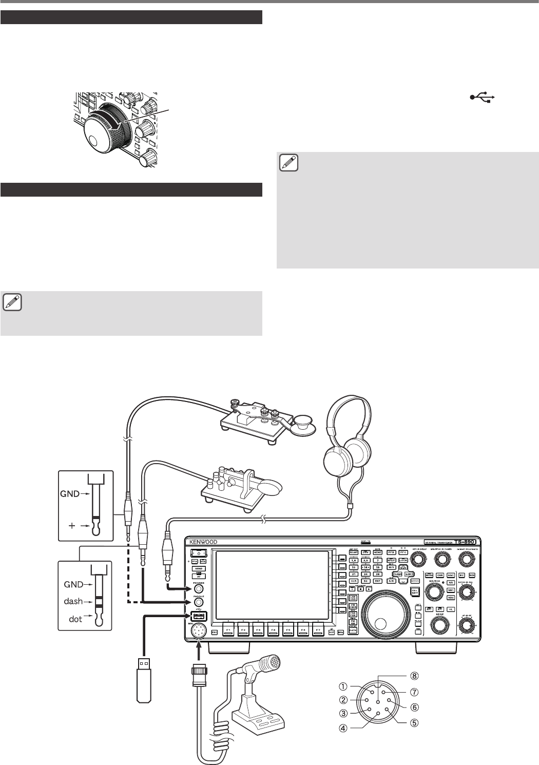
Torque Adjustment with Tuning Control
The Tuning control allows the rotational torque (weight) to be
adjusted according to the user’s preference. With the ring at the
base of the Tuning control fixed, turning the Tuning control to the
right increases the rotational torque, while turning to the left
decreases it.
.
Ring
Connection of Accessories (Front Panel)
■Headphones (PHONES)
Monaural and stereo headphones (4 to 32 Ω, standard: 8 Ω/plug:
Φ6.3 mm) can be used with this transceiver.
When headphones are connected, sound will not be output from
the built-in speakers (or optional external speakers). The following
optional headphones are compatible with this transceiver.
●HS-5 ●HS-6
●The volume may be louder for headphones with a higher
impedance.
●The audio output is monaural even when stereo
headphones are connected.
■Paddle (PADDLE)
For CW operation using the built-in electronic keyer, connect a
keyer paddle to the PADDLE jack. A Φ6.3 mm three-pronged plug
is used for the paddle. Also, a straight key can be connected to the
PADDLE jack. In this case, change the setting of Menu [5-00] to
“Straight Key”. (Refer to Chapter 3 for details on menu operation.)
■USB Flash Drive/USB Keyboard ( )
For connecting a commercially available USB flash drive or USB
keyboard.
Plug the USB flash drive or USB keyboard firmly into the (USB-A)
connector.
●Do not remove the USB flash drive while reading or
writing files or while the USB flash drive is being
accessed by this transceiver. Also, do not turn off the
power of this transceiver.
●Always remove the USB flash drive after ensuring that
this can be done safely to prevent data in the USB flash
drive from being damaged. (USB/File Management
Menu “Safe Removal of USB Flash Drive”)
●A USB flash drive or USB keyboard can be connected to
the connector on the front panel and rear panel
respectively.
■Microphone (MIC)
Microphones with an impedance of 250 Ω to 600 Ω can be used.
Insert the microphone plug fully into the MIC connector of this
transceiver and tighten it firmly using the fastening ring.
The following microphones (sold separately) are compatible with
this transceiver.
●MC-43S ● MC-60A ● MC-90 ●MC-47
The following microphones are not compatible with this transceiver.
●MC-44 ●MC-44DM ●MC-45 ●MC-45DM
.
Microphone Connector
(View from Front Panel)
8V (10mA max)
NC
GND (MIC)
GND (STBY)
UP
DOWN
PTT
MIC
Microphone
(Optional or Commercially
Available)
USB Flash Drive (Commercially
Available) or USB Keyboard
(Commercially Available)
Front Panel
Paddle (Commercially Available)
Straight Key (Commercially Available)
Headphones
(Optional or Commercially
Available)
1 INSTALLATION AND CONNECTION
1-2
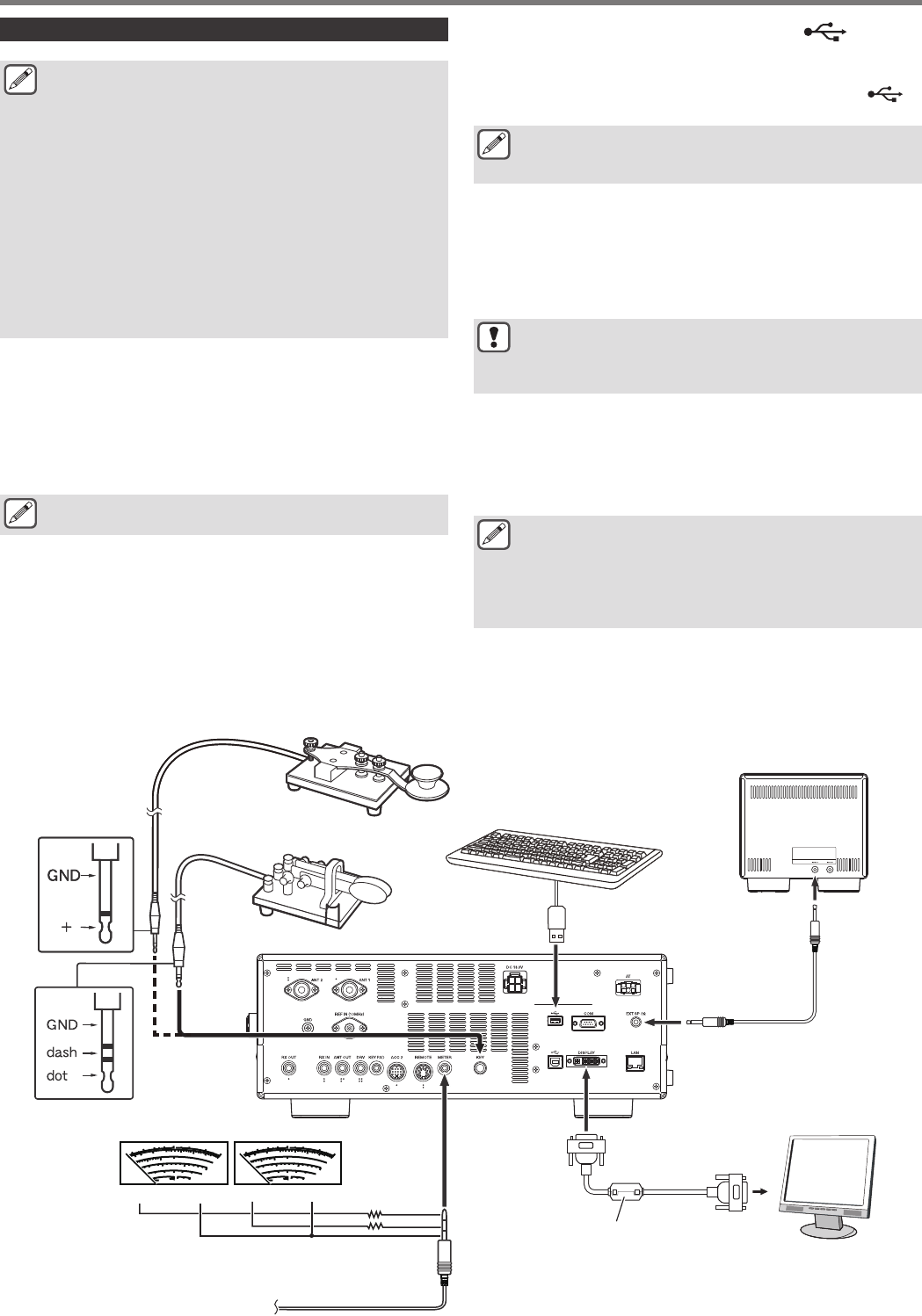
Connection of Accessories (Rear Panel)
●A cable exceeding 3 m (9.8 feet) may not be connected
to a connector below.
•KEY jack
•ACC 2 connector
•REMOTE connector
•METER jack
•DRV connector
•KEYPAD jack
•COM connector
•EXT.SP jack
•DISPLAY connector
•LAN connector
•PHONES jack
•PADDLE jack
•MIC connector
■Key for CW (KEY)
For CW operation without using the built-in electronic keyer,
connect the plug of an electronic key, bug key, external electronic
keyer or PC keyer to the KEY jack. Use a Φ3.5 mm two-pronged
plug. Positive keying needs to be used for external electronic
keyers and PC keyers. Use a shielded cable to connect the key
and this transceiver.
●For more detailed explanation on the built-in keyer, refer
to “Electronic Keyer”. (5-13)
■USB Flash Drive/USB Keyboard ( )
For connecting a commercially available USB flash drive or USB
keyboard.
Plug the USB flash drive or USB keyboard firmly into the
(USB-A) connector.
●A USB flash drive or USB keyboard can be connected to
the connector on the front panel and rear panel
respectively.
■Keypad (KEYPAD)
For connecting a self-made PF keypad.
■External Speaker (EXT. SP 8Ω)
For connecting an external speaker.
●The EXT. SP 8 Ω is used exclusively for connecting an
external speaker. Due to the loud audio output, hearing
may be impaired when headphones are used. Do not
connect headphones.
■External Display (DISPLAY)
Connect this transceiver with an external display using a
commercially available DVI cable.
Doing so enables information displayed on the screen of this
transceiver to be shown on the external display.
●Use an external display with a resolution of 800 x 600 or
848 x 480.
●This transceiver supports digital and analog outputs.
●If the display to connect uses a D-sub terminal, make use
of a commercially available DVI/D-Sub conversion
adapter.
■External Meter (METER)
For connecting a commercially available meter.
.
(+) (−) (+) (−)
9
3
44 52V vd
ALC
COMP
10
5
20
10
dB
+20
+60dB
250W
15A
∞
7
5
3
1
S
PO
SWR
Id
9
3
44 52V vd
ALC
COMP
10
5
20
10
dB
+20
+60dB
250W
15A
∞
7
5
3
1
S
PO
SWR
Id
External Speaker (Optional or
Commercially Available)
USB Keyboard (Commercially Available) or
USB Flash Drive (Commercially Available)
Straight Key (Commercially Available)
Paddle (Commercially Available)
Rear Panel
Meter 2Meter 1
Φ3.5 mm
Stereo
Add a resistor as necessary.
Meter (Commercially
Available)
DVI Cable
To DVI Port
External Display
(Commercially Available)
(E type)
INSTALLATION AND CONNECTION 1
1-3
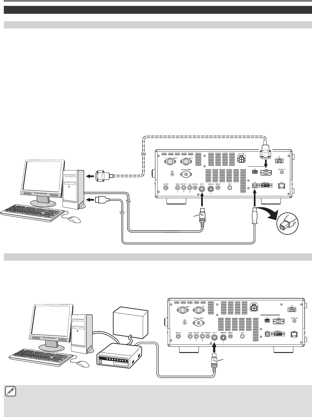
Connection with Data Communication Equipment
PC Connection
This transceiver is equipped with connectors (ACC 2 and USB) for exchanging audio signals with the supplied equipment for data
communication using an external device. These connectors are collectively referred to as data communication connectors in this manual.
To make use of data communication such as RTTY (AFSK), PSK31, SSTV, JT65 and FT8 using data communication software that
employs the sound function of a PC and with this transceiver configured to the DATA mode (SSB-DATA, FM-DATA, AM-DATA), set up
the connection as follows.
•When using the USB audio function: connect to the USB port of the PC. Data communication with only the USB cable connection is
possible by making use of data VOX or PC commands (“TX1;” to start transmission and “RX;” to end transmission) to switch between
transmission and reception. (For details on the configuration of the input sound source in the DATA mode and the VOX function, refer
to page 8-1.) Before connecting this transceiver with a PC using a USB cable, download also a virtual COM port driver and install
it on the PC.
http://www.kenwood.com/i/products/info/amateur/software_download.html
•When using an ACC 2 connector: connect the audio output line of the PC to pin 11 (ANI) of the ACC 2 connector and the audio input
line of the PC to pin 3 (ANO). Pin 9 (PKS) of the ACC 2 connector, data VOX or PC commands (“TX1;” to start transmission and “RX;”
to end transmission) are used to switch between transmission and reception. When using PC commands, connect the transceiver
and the PC with a RS-232C straight cable or a USB cable.
.
USB (B) Connector
USB Cable
Supplied 13-Pin DIN Plug
(Use the supplied 13-pin DIN
plug to make your own
connection cable.)
To USB Port
PC
To Audio Input/Output Port
To RS-232C
Serial Port
(Female)
TS-890
RS-232C Straight Cable
TNC Connection
For packet communication and the like using an external TNC (terminal node controller) with this transceiver configured to DATA mode,
make use of the ACC 2 connector. Connect the modulation output line, demodulation input line and TX control (PTT) of the external
TNC to pin 11 (ANI), pin 3 (ANO) and to pin 13 (PKS) of the ACC 2 connector respectively. (For details on the configuration of the input
sound source in the DATA mode, refer to page 8-1.)
.
Supplied 13-Pin DIN Plug (Use the
supplied 13-pin DIN plug to make
your own connection cable.)
TS-890
Power Supply Unit for TNC
TNC
PC
●USB cable and RS-232C straight cable are not supplied with this transceiver. Please purchase commercially available cables.
●Delays may occur when using USB audio, and there may also be audio interruptions depending on the performance and load
of the PC.
●Place this transceiver far enough from the PC and TNC so that noise will not be picked up.
●For data communication software settings, refer to the instruction manual or Help file of the software in use.
1 INSTALLATION AND CONNECTION
1-4
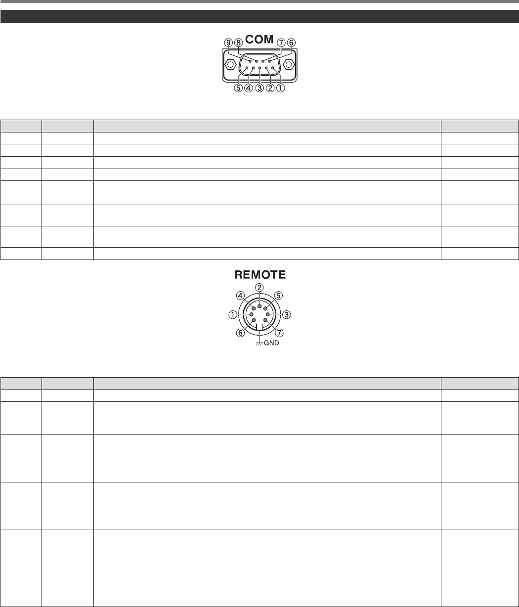
Terminal Descriptions
.
COM Connector
Pin No. Pin Name Function Input/Output
1 NC No connection —
2 RXD Sends serial data to PC. O
3 TXD Receives serial data from PC. I
4 NC No connection —
5 GND Signal ground —
6 NC No connection —
7 RTS Sends signal from the PC to this transceiver. If the PC is unable to accept incoming data, an “L” level
signal is output from the PC to this transceiver and data will not be sent in this case. I
8 CTS Sends signal from this transceiver to the PC. If this transceiver is unable to accept incoming data, an
“L” level signal is output from this transceiver to the PC and input of incoming data will be forbidden. O
9 NC No connection —
.
GND:
Connect to metal shield.
REMOTE Connector
Pin No. Pin Name Function Input/Output
1 SPO Speaker out O
2 COM Common terminal of the built-in relay for linear amplifier control I/O
3 SS PTT input
Sends signal by grounding the SS terminal. I
4 MKE
Make terminal of the built-in relay for linear amplifier control
•The make terminal can be connected to the common terminal during transmission by configuring
“Internal Relay Control” of the linear amplifier menu.
Rated control capacity of relay contact: 2 A/ 30 V DC (resistance load)
Maximum allowable voltage of relay contact: 220 V DC, 250 V AC
I/O
5 BRK
Break terminal of the built-in relay for linear amplifier control
The break terminal can be connected with the common terminal when the latter is not connected to
a make terminal.
Rated control capacity of relay contact: 2 A/ 30 V DC (resistance load)
Maximum allowable voltage of relay contact: 220 V DC, 250 V AC
I/O
6 ALC ALC input from the linear amplifier I
7 LKY
Linear amplifier control output
•The output logic during transmission can be configured using “Keying Logic” of the linear amplifier
menu.
“Active High”: Outputs DC 12 V during transmission. The maximum output current is 100 mA.
“Active Low”: Switches to the “L” level (GND and short) during transmission. When an external bias
is applied while receiving is in progress, the signal switches to the “H” level. Voltage and current not
higher than DC 50 V and 100 mA respectively can be controlled.
O
INSTALLATION AND CONNECTION 1
1-5
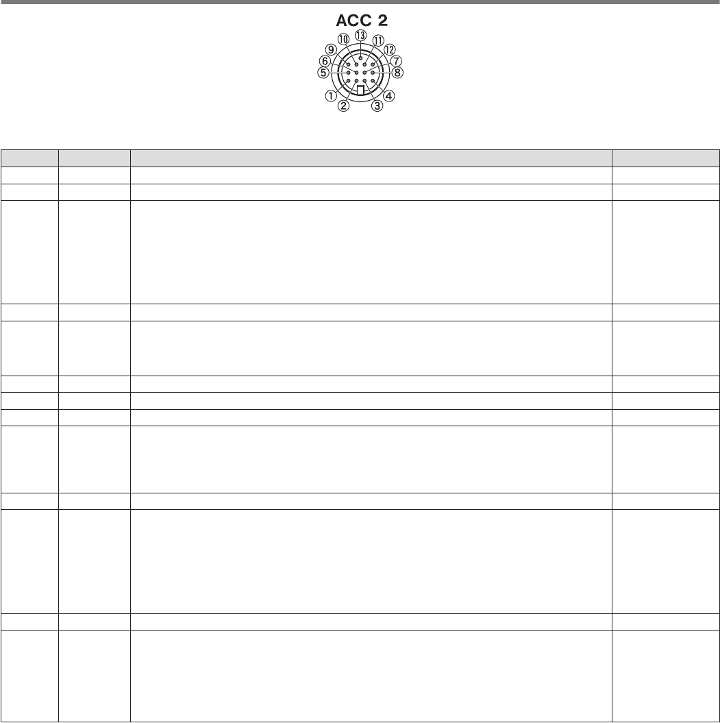
.
ACC 2 Connector
Pin No. Pin Name Function Input/Output
— NC No connection —
2 RTTY RTTY control terminal (FSK key input) I
3 ANO
Audio output
•Connect to the audio input of the TNC, MCP or PC (or PC connection interface).
•The audio output level is independent of the AF volume control knob on the front panel.
•The audio output level can be adjusted in Menu [7-09]. Adjust it to an appropriate level.
•When the audio output level is configured to the default value of “50” in Menu [7-09], the peak-to-
peak voltage is approximately 0.5 V p-p in the case of standard modulation signals. Altering the
audio output level between “0” and “100” changes the peak-to-peak voltage level between
approximately 0 Vp-p and 1.2 Vp-p. (Impedance 10 kΩ)
O
4 GND Signal ground —
5 PSQ
Squelch control output
•Connect to the squelch input of the TNC, MCP or PC connection interface.
•When squelch is open: Low impedance
•When squelch is closed: High impedance
O
6 MET 1 Meter level output 1 O
7 NC No connection —
8 GND Signal ground —
9 PKS
PTT input for data communication (DATA SEND)
•Connect to the PTT output of the TNC, MCP or PC connection interface.
•Signal can be transmitted by connecting the PKS terminal to GND.
•The PKS terminal mutes unnecessary modulation input signals during transmission.
“Configuration of the Input Path of TX Audio”
I
10 MET2 Meter level output 2 O
11 ANI
Audio input for data communication
•Connect to the audio output of the TNC, MCP or PC (or PC connection interface).
•The audio input level is independent of MIC GAIN on the front panel.
•The audio input level can be adjusted in Menu [7-07].
•Standard modulation can be obtained with an input of approximately 10 mVrms in the default
setting of “50” in Menu [7-09]. Altering the audio input level between “0” and “100” changes the
standard modulation input level between approximately “almost no modulation” and approx. 1
mVrms. (Impedance 10 kΩ)
I
12 GND Signal ground —
13 SS
PTT input
•This is the same terminal as pin 2 (SS terminal) of the MIC connector on the front panel and pin 3
(SS terminal) of the REMOTE connector.
•It has the same behavior as pressing [SEND] on the front panel.
•Signal can be transmitted by connecting the SS terminal to GND.
•The SS terminal mutes unnecessary modulation input signals during transmission. “Configuration
of the Input Path of TX Audio”
I
1 INSTALLATION AND CONNECTION
1-6
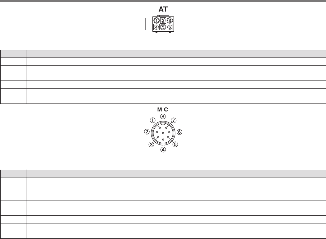
.
EXT. AT Connector
Pin No. Pin Name Function Input/Output
1 GND Signal ground —
2 TT EXT.AT connector (TTI/TTO) I/O
3 GND Signal ground —
4 NC No connection —
5 TS EXT.AT connector (TSI/TSO) I/O
6 14S DC 13.8 V power supply for EXT.AT O
.
MIC Connector
Pin No. Pin Name Function Input/Output
1 MIC MIC signal input I
2 SS MIC standby (PTT) control I
3 MD MIC DOWN control I
4 MU MIC UP control I
5 8 A DC 8 V power supply for MIC O
6 NC No connection —
7 MSG MIC ground —
8 MCG Signal ground —
INSTALLATION AND CONNECTION 1
1-7

.
1-8
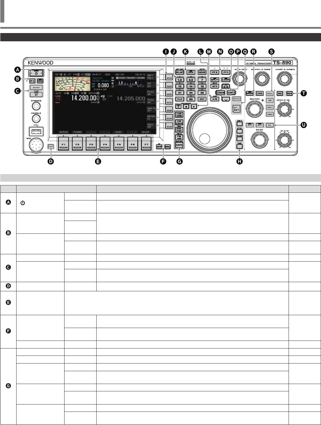
Front Panel
.
Panel Key Behavior
Key Behavior Refer to
.[ ]
Press Turns on the power.
4-1
Press and
hold Turns off the power.
.
[PF A]
Press
Activates the registered function. 16-2
Press and
hold
[VOX]
Press Turns ON/OFF the VOX function. 8-1
Press and
hold Displays the VOX configuration screen. 8-2
.
[SEND] Press Starts/ends transmission. 4-7
[AT]
Press Turns ON/OFF the antenna tuner.
4-11
Press and
hold Starts antenna tuning.
.[ESC] Press Exits the configuration screen. –
.
[F1] to [F7]
(Horizontally
Arrayed F)
Activates the function according to the key guide at the bottom of the screen.
(Henceforth represented as F1 [XXX] to F7 [XXX] in this manual.)
Refer to “List of Function Key Behaviors (Standard Mode Screen)” for functions of the F key on the normal
screen.
2-4
.
[SCP]
Press Displays the bandscope.
Switches the scope screen. 7-1
7-6
Press and
hold Displays the audio scope.
Switches between bandscope and audio scope.
[MHz] Press Turns ON/OFF the MHz step function. 4-6
.
[LSB/USB] Press Switches between the LSB and USB modes. 4-4
[CW/CW-R] Press Switches between the CW and CW-R modes. 4-4
[FSK/PSK]
Press Switches between the FSK and PSK modes.
4-4
Press and
hold Switches between reverse and normal in the FSK/PSK mode.
[FM/AM]
Press Switches between the FM and AM modes.
4-4
Press and
hold Switches between FM narrow and FM normal.
[DATA]
Press Switches the DATA mode. 4-4
Press and
hold Displays the input source configuration screen for the TX audio. 8-1
NAMES AND FUNCTIONS OF PARTS 2
2 NAMES AND FUNCTIONS OF PARTS
2-1

Key Behavior Refer to
.
[CW T.] Press Activates the CW auto tune function. 5-9
[IF FIL]
Press Switches between receiver (RX) filters A, B and C. 6-1
Press and
hold Displays the RX Filter screen. 6-2
[FIL CLR] Press Restores the passband of the RX filter that has been changed to the preset value. 6-4
[FINE] Press Turns ON/OFF the FINE-tuning function. 4-5
.
[ ] to [ ] (Vertically
Arrayed F)
Activates the function according to the key guide on the right side of the screen. (Henceforth represented
as F [XXX] in this manual.)
Refer to “List of Function Key Behaviors (Standard Mode Screen)” for functions of the F key on the normal
screen.
2-4
.
[0 (50)] to [9 (28)] Press For selecting a frequency band and switching band memory. 4-3
[CLR] Press Cancels the direct frequency input mode. –
[ENT] Press Turns on the direct frequency input mode. 4-6
.
[RX ANT]
Press Turns ON/OFF the RX antenna. 4-10
Press and
hold Turns ON/OFF the antenna output function for the external receiver. 16-15
[DRV] Press Turns ON/OFF the drive output function. 4-10
[GENE]
Press For selecting a general coverage band. 4-3
Press and
hold Turns ON/OFF the transverter function. 16-15
.
[ ]
Press Starts, pauses or resumes manual recording. 12-3
Press and
hold Saves the constantly recorded audio file. 12-3
[]Press Stops audio recording or playback. 12-4
[ ] Press Starts, pauses or resumes playback.
.[A/B]
Press Switches between VFO A and VFO B. 4-2
Press and
hold Aligns the frequency and mode of VFO A and VFO B. 5-1
.
[PF B]
Press
Activates the registered function. 16-2
Press and
hold
[PF C]
Press
Activates the registered function. 16-2
Press and
hold
.
[SPLIT]
Press Turns ON/OFF the split mode. 5-1
Press and
hold Starts configuration of the frequency for split operation. 5-1
[LOCK] Press Turns ON/OFF the frequency lock function. 4-7
[M/V]
Press Switches between the memory channel and VFO mode. 9-2
Press and
hold Copies the memory channel data and quick memory channel data to VFO. 9-3
2 NAMES AND FUNCTIONS OF PARTS
2-2

Key Behavior Refer to
.
[ M.IN] Press
Displays the memory channel list screen. 9-1
Registers a memory channel. 9-1
Switches the menu mode item. 3-1
[<Q-M.IN] Press Registers a quick memory channel. 9-5
Switches the menu mode item. 3-1
[Q-MR>]
Press Calls up a quick memory channel. 9-5
Switches the menu mode item. 3-1
Press and
hold Deletes all quick memory channels. 9-5
[ ] Press Switches the menu mode item. 3-1
.
[MENU] Press Turns ON/OFF the menu mode. 3-1
[TF-SET] Press Turns ON/OFF TF-SET. (ON while it is being pressed.) 5-2
.
[MONI]
Press Turns ON/OFF the TX monitor function. 8-3
Press and
hold Displays the TX monitor level configuration screen. 8-3
[CAR] Press Displays the carrier level configuration screen. 5-8
.
[AGC]
Press Switches the AGC time constant [FAST, MID, SLOW]. 5-2
Press and
hold Displays the AGC configuration screen. 5-2
[NR]
Press Switches the mode of the noise reduction function [OFF/NR1/NR2]. 6-7
Press and
hold Displays the NR1 configuration screen. (When Noise Reduction 1 is ON)
Displays the NR2 configuration screen. (When Noise Reduction 2 is ON) 6-7
[NB1]
Press Turns ON/OFF the Noise Blanker 1. 6-5
Press and
hold Displays the NB1 configuration screen. 6-5
[NB2]
Press Turns ON/OFF the Noise Blanker 2. 6-5
Press and
hold Displays the NB2 configuration screen. 6-6
.
[BC] Press Switches the mode of the beat canceler function [OFF/BC1/BC2]. 6-8
[NCH]
Press Turns ON/OFF the notch filter. 6-6
Press and
hold Switches the bandwidth of the notch filter [Normal, Middle, Wide]. 6-7
.
[RIT]
Press Turns ON/OFF the RIT function. 5-7
Press and
hold Shifts the RX frequency via RIT. 5-7
[XIT]
Press Turns ON/OFF the XIT function. 5-7
Press and
hold Shifts the TX frequency via XIT. 5-7
[CL] Press Clears the RIT or RIT/XIT frequency. 5-7
NAMES AND FUNCTIONS OF PARTS 2
2-3
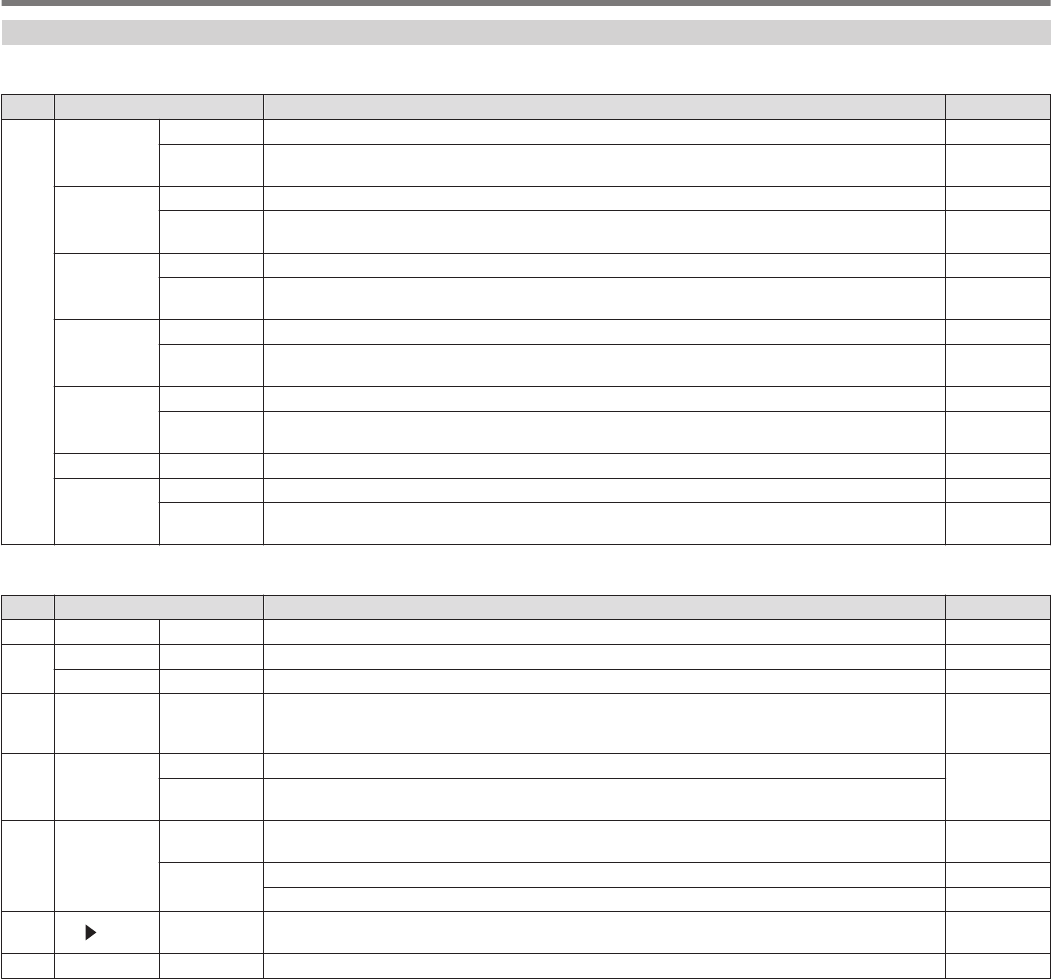
List of Function Key Behaviors (Standard Mode Screen)
Function Keys (Vertically Arrayed)
Key Guide Behavior Refer to
F
[ANT/PRE]
Press Switches the preamplifier. (OFF/ PRE 1/ PRE 2) 5-6
Press and
hold Switches between “ANT 1” and “ANT 2”. 4-10
[ATT]
Press Switches the attenuation level of the attenuator. (OFF/ 6 dB/ 12 dB/ 18 dB) 6-1
Press and
hold Switches in the reverse order. 6-1
[RX EQ]
Press Turns ON/OFF the RX equalizer. 5-4
Press and
hold Displays the RX equalizer configuration screen. 5-4
[TX EQ]
Press Turns ON/OFF the TX equalizer. 8-5
Press and
hold Displays the TX equalizer configuration screen. 8-5
[MAX-Po]
Press Turns ON/OFF the TX output power limiter. 4-8
Press and
hold Displays the TX output power limiter configuration screen. 4-8
[METER] Press Switches the meter display. 4-8
[PROC]
Press Turns ON/OFF the speech processor. 8-3
Press and
hold Displays the Speech Processor configuration screen. 8-3
Function Keys (Horizontally Arrayed)
Key Guide Behavior Refer to
F1 [RX PLAY] Press Displays the audio recording file screen. 12-4
F2 [TX MSG] Press Displays the voice message screen. (Displayed in the SSB, AM and FM modes.) 12-1
[KEYER] Press Displays the CW message screen. (Displayed in the CW mode.) 5-14
F3 [DECODE] Press Displays the communication screen. (Displayed in the CW, FSK and PSK modes.) 5-10
5-22
5-22
F4 [TONE]
Press Switches in the sequence of: “TONE” → “CTCSS” → “CROSS TONE”. (Displayed in the FM mode.) 5-28
5-30
5-30
Press and
hold Displays the TONE frequency, CTCSS frequency or cross tone configuration screen.
F5 [SCAN]
Press Starts/stops scanning. 10-1
10-3
Press and
hold
Displays the VFO/Program Scan segment screen. (Displayed in the VFO mode.) 10-1
Displays the memory scan group screen. (Displayed in the memory channel mode.) 10-3
F6 [M VFO] Press Shifts the memory.
(Displayed in the memory channel and quick memory channel modes.) 9-3
9-6
F7 [M.LIST] Press Displays the memory channel list. 9-1
2 NAMES AND FUNCTIONS OF PARTS
2-4
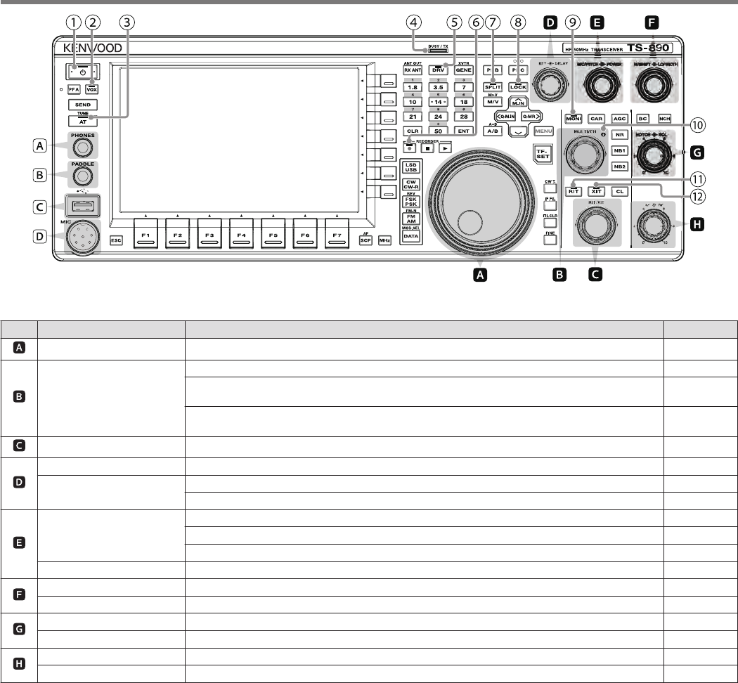
.
List of Control Knob Behaviors
Control Behavior Refer to
.Tuning Aligns the TX and RX frequencies. 4-5
.[MULTI/CH]
Switches the frequency at a fast speed. (Available in the VFO mode.) 4-5
Switches the channel number. (Available in the memory channel and quick memory channel
modes.) 9-2
Switches the item to configure or configured value. (Available when a configuration screen is
displayed.) 3-1
.[RIT/XIT] Changes the RIT/XIT frequency. 5-7
.
[KEY] Adjusts the keying speed. 5-13
[DELAY] Adjusts the break-in delay time. (When the TX mode is configured to CW.) 5-8
Adjusts the VOX delay time. (When the TX mode is configured to SSB, FM or AM.) 8-2
.
[MIC/PITCH]
Adjusts the microphone gain. (When the TX mode is configured to SSB or AM.) 4-7
Adjusts the sidetone/pitch frequency. (When the TX mode is configured to CW.) 5-9
Adjusts the speech processor output level. (When the speech processor is ON.) 8-3
[POWER] Changes the TX output power level. 4-7
.
[HI/SHIFT] Changes the RX filter (high-cut frequency or shift frequency). 6-3
[LO/WIDTH] Changes the RX filter (low-cut frequency or width frequency). 6-3
.
[NOTCH] Adjusts the notch frequency. 6-6
[SQL] Adjusts the squelch level. 4-2
.
[AF] Adjusts the receiving volume. 4-2
[RF] Adjusts the RF gain. 4-2
NAMES AND FUNCTIONS OF PARTS 2
2-5
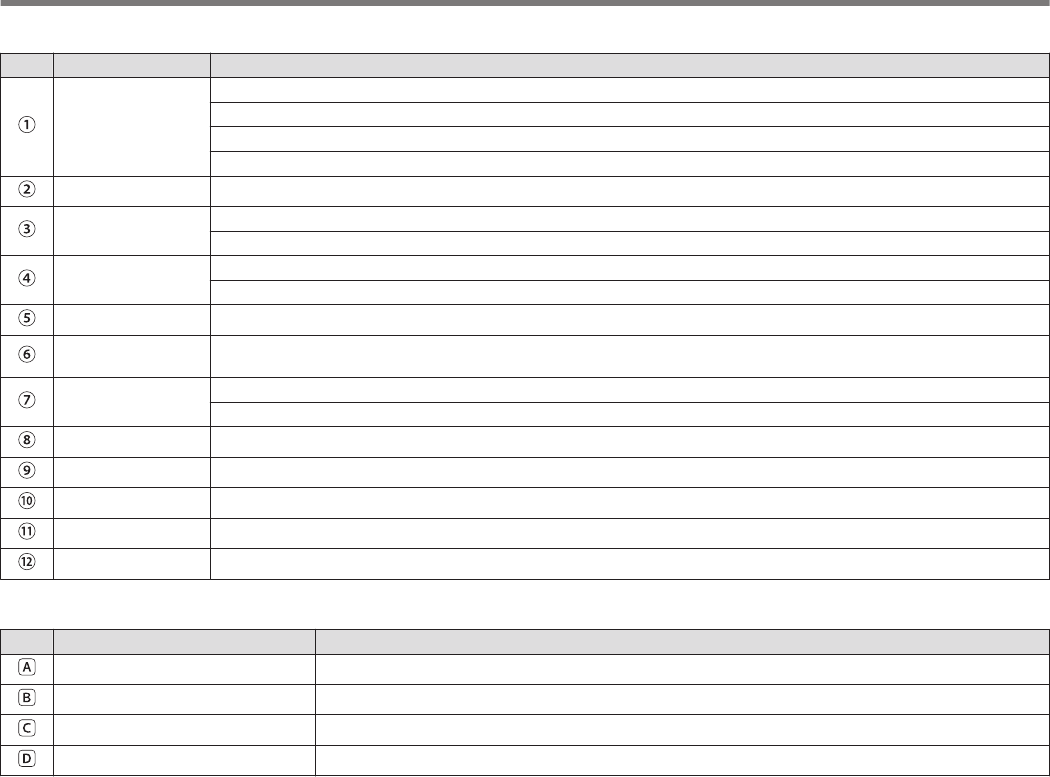
List of LED Behaviors
LED Behavior
.[POWER]
When power is OFF: light off
When power is ON: lights up in green
When power is OFF with timer activated: lights up in orange
When timer is starting up: blinks in orange
.[VOX] Lights up when the VOX function is enabled.
.[AT] Lights up when the antenna tuner is ON.
Blinks during antenna tuning.
.[BUSY/TX] Lights up in green when squelch opens upon receiving a signal.
Lights up in red when transmission is in progress.
.[DRV] Lights up when drive output is ON.
.[REC] Lights up during manual recording (including when recording is paused).
Blinks for 1 second at the start of saving the constantly recorded audio.
.[SPLIT] Lights up in the split mode.
Blinks during configuration of the split frequency.
.[LOCK] Lights up when the frequency lock function is enabled.
.[MONI] Lights up when the TX monitor function is enabled.
.[MULTI/CH] Lights up when a configuration screen is displayed (when adjustments can be made using the [MULTI/CH] control).
.[RIT] Lights up when the RIT function is enabled.
.[XIT] Lights up when the XIT function is enabled.
Connectors and Jacks
Name Description
.<PHONES> Jack Jack for connecting to headphones.
.<PADDLE> Jack Jack for connecting a paddle while running in the CW mode.
.<USB-A> Connector Connector for connecting a USB flash drive or USB keyboard.
.<MIC> Connector Connector for connecting a microphone.
2 NAMES AND FUNCTIONS OF PARTS
2-6
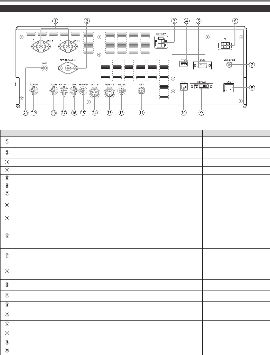
Rear Panel
.
Connectors and Jacks on the Rear Panel
No. Name Description Remarks
.
<ANT 1> Connector
<ANT 2> Connector M-type coaxial connector for connecting the antenna.
.<REF IN (10MHz)> Connector For input of 10 MHz signals when using an external reference
frequency. •Input impedance: 50 Ω
•Input: 0 dBm ±10 dB
.<DC13.8V> Connector For connecting a regulated DC power supply.
.<USB-A> Connector Connector for connecting a USB flash drive or USB keyboard.
.<COM> Connector RS-232C connector for connecting a PC or external device.
.<AT> Connector Connector for controlling an external amplifier tuner.
.<EXT.SP> Jack For connecting an external speaker.
.<LAN> Connector Connector for connecting a PC or LAN when running with the KNS
(KENWOOD NETWORK COMMAND SYSTEM) or for automatic
correction of the clock time.
.<DISPLAY> Connector DVI-I connector for connecting an external monitor. Both analog
and digital signals can be output.
.<USB-B> Connector
Connector for connecting a PC. It is used to control this transceiver
using the ARCP-890 as well as to input and output signals for
transmission and reception via the digital communication
application of a PC. It can be switched between transmission and
reception by changing the menu setting and keying.
.<KEY> Jack For connecting an electronic key (straight key, bug key, external
electronic key, etc.) when running in the CW mode. This can be
configured to a jack for paddle connection in the menu.
.<METER> Terminal For connecting a commercially available meter. •Output impedance: 4.7 Ω
•Allowable open-end voltage
output: 0 to 5 V
.<REMOTE> Connector For connecting a linear amplifier. (Use the supplied 7-pin DIN plug
for the connection.)
.<ACC 2> Connector For connecting an external device such as an external terminal.
(Use the supplied 13-pin DIN plug for the connection.)
.<KEYPAD> Jack For connecting a self-made PF keypad.
.<DRV> Connector For connecting a transverter or linear amplifier. •Output impedance: 50 Ω
•Output: Approx. 1 mW (0 dBm)
.<ANT OUT> Connector For connecting devices such as an external receiver.
.<RX IN> Connector For connecting an RX antenna, external bandpass filter, transverter
and the like.
.<RX OUT> Connector For connecting an external bandpass filter and the like.
.<GND> Terminal For connecting a ground wire.
NAMES AND FUNCTIONS OF PARTS 2
2-7
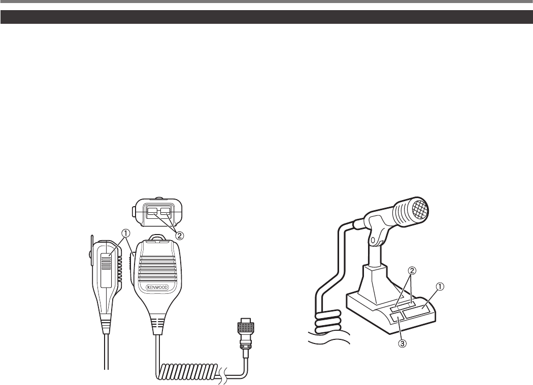
Microphone (Optional)
APTT (Push-to-talk) Switch
Switches to the transmitting state while this switch is being pressed. Releasing the switch restores the transceiver to the receiving
state.
BUP/ DOWN Keys
For scrolling up/down the items in one of the following modes, such as scrolling up/down the VFO frequencies.
Pressing and holding down the key enables continuous scrolling. It can also be configured for use as a PF key.
•VFO mode: Scrolls up/down the VFO frequencies
•Memory channel mode: Scrolls up/down the memory channel numbers
•Memory scroll mode: Scrolls up/down the memory scroll numbers
•Mic paddle mode: For paddle (dot/dash) input
•Menu mode: Displays the previous or next option
CLOCK Key (MC-60A/ MC-90 only)
Pressing this key activates the key lock and switches to the transmitting state. Pressing it again restores the key to the original position
and switches to the receiving state.
.
PTT
DWN UP
MC-43S
MC-60A/MC-90
2 NAMES AND FUNCTIONS OF PARTS
2-8
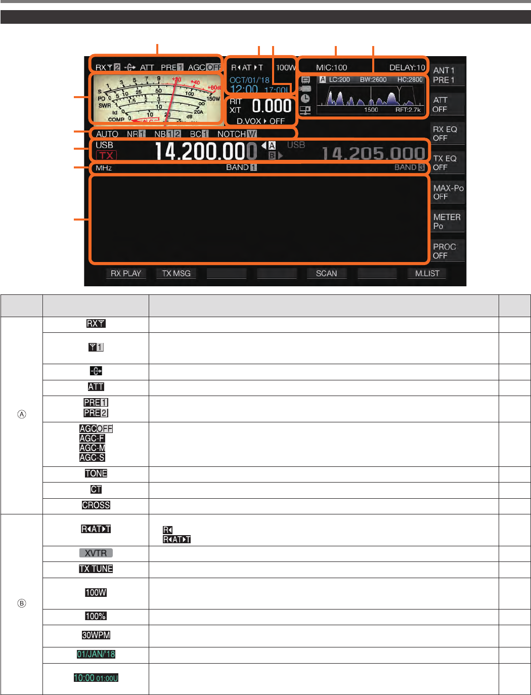
Screen
.
ⒶⒷⒺ
Ⓒ
Ⓕ
Ⓖ
Ⓗ
Ⓘ
Ⓙ
Ⓓ
Area Display Description Refer
to
.
.Appears when an RX antenna is functioning. 4-10
.
Displays the antenna number. Switches the antenna number accordingly when the antenna is
switched. It is not displayed when the TX output power destination of the transverter is drive output
(DRV). 4-10
.Appears when antenna output for the external receiver is functioning. 16-15
.Appears when the receiving attenuator is configured to “6 dB”, “12 dB” or “18 dB”. 6-1
.
Appears when the receive preamplifier 1 is ON.
Appears when the receive preamplifier 2 is ON. 5-6
.
Appears when AGC is OFF.
Appears when AGC is configured to “FAST”.
Appears when AGC is configured to “MID”.
Appears when AGC is configured to “SLOW”.
5-2
.Appears when Tone is ON. 5-29
.Appears when CTCSS is ON. 5-30
.Appears when Cross Tone is ON. 5-30
.
.
Displays the antenna tuner function and operating status.
<< >> lights up when the antenna tuner is ON during reception.
<< >> blinks while antenna tuning is in progress.
4-11
.Appears when the transverter is ON. 16-15
.Blinks while TX tuning is ON. 8-7
.
Displays the TX output power level. (Not displayed when the TX output power destination is drive
output (DRV).)
Displayed in yellow when the output power is limited by the TX output power limiter function. 4-7
.Displays the drive output level. (Displayed when drive output is ON.) 4-10
.
Displays the keying speed. Turning the [KEY SPEED] control displays the keying speed (4 to 60
words/minute) in the TX output power area for 2 seconds. 5-13
.Displays the date of the local clock. The date can be displayed in the UK, US or Japanese format. 14-1
.
Displays the time (24-hour format).
Left: Displays the time of the local clock.
Right: Displays the time of the auxiliary clock (indicated by the character “U” at the end). 14-1
NAMES AND FUNCTIONS OF PARTS 2
2-9
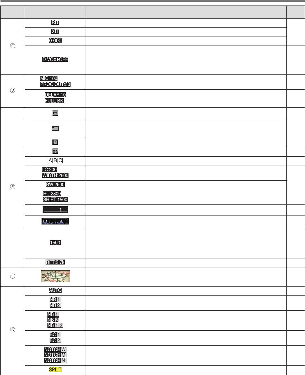
Area Display Description Refer
to
.
.Appears when the RIT function is enabled.
5-7
.Appears when the XIT function is enabled.
.Displays the RIT or XIT frequency (between -9.999 and 9.999 kHz).
.
Appears according to the input path of the TX audio selected by the data VOX function.
OFF: Appears when sound is not input from all paths.
ACC 2: Appears when ACC 2 is used as the audio source input.
USB: Appears when USB AUDIO is used as the audio source input.
LAN: Appears when LAN is used as the audio source input.
8-1
.
.
Displays the microphone gain. (Displayed when the speech processor is OFF)
Displays the speech processor output level. (Displayed when the speech processor is ON) 4-7
8-4
.
Displays the VOX delay time when the transmitting end is in the SSB, AM or FM mode.
Displays the break-in delay time when the transmitting end is in the CW mode.
“FULL-BK” is displayed during full break-in. 5-8
.
.
This is an icon of the internal memory. The icon is displayed in red when the remaining space is
running low.
11-1
.
The icon starts to blink when a USB flash drive is connected, and lights up when the USB flash drive
is recognized by this transceiver.
The icon is displayed in red when the remaining space is running low.
.Appears when the timer function is enabled. 14-3
.Appears when a KNS user is connected to this transceiver. 15-2
.Displays the selected RX filter (A, B or C). 6-1
.
Displays the low-cut frequency of the RX filter.
Displays the width frequency of the RX filter.
6-3
.Displays the bandwidth of the RX filter.
.
Displays the low-cut frequency of the RX filter.
Displays the shift frequency of the RX filter.
.Displays the position of the notch frequency when the notch filter is ON. 6-6
.
Displays the passband/audio FFT.
Displays the audio FFT spectrum of the RX or TX audio. 6-1
8-4
.
Displays the center indicator.
•Indicates the pitch frequency when in the CW mode.
•Indicates the center frequency of the passband when in the FSK or PSK mode.
•Indicates the center frequency of the horizontal axis that is currently displayed when in the SSB,
FM or AM mode.
5-9
5-17
5-22
.Displays the selected bandwidth for the roofing filter. 6-2
.
.
Meter display
•This can be switched to an analog or digital display.
•Display of the information on the TX meter can be switched when an analog meter is displayed.
4-9
.
.Appears when the auto mode is ON. 4-4
.
Appears when Noise Reduction 1 (NR1) is ON.
Appears when Noise Reduction 2 (NR2) is ON. 6-7
.
Appears when Noise Blanker 1 (NB1) is ON.
Appears when Noise Blanker 2 (NB2) is ON.
Appears when both Noise Blanker 1 and 2 are ON. 6-5
.
Appears when Beat Canceler 1 (BC1) is ON.
Appears when Beat Canceler 2 (BC2) is ON. 6-8
.
Appears when the notch filter is ON and “Wide” is selected for the bandwidth.
Appears when the notch filter is ON and “Middle” is selected for the bandwidth.
Appears when the notch filter is ON and “Narrow” is selected for the bandwidth. 6-6
.Appears during split operation. 5-1
2 NAMES AND FUNCTIONS OF PARTS
2-10
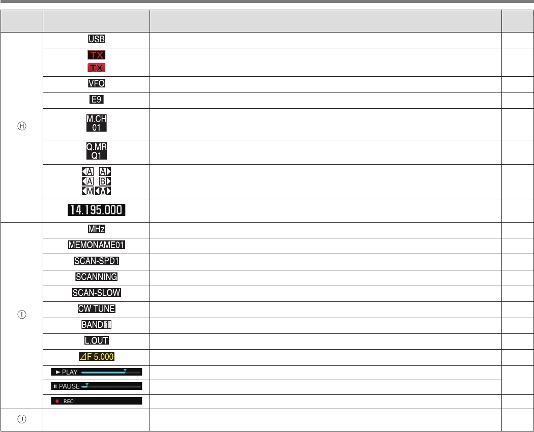
Area Display Description Refer
to
.
.Displays the mode that is currently running. “-D” is displayed when in the data mode. 4-4
.
.
Appears while receiving in the TX band.
Appears while transmitting in the TX band. “-R” is displayed when in the reverse mode. –
.Appears when configuring the frequency of the VFO mode or auto mode. –
.Displays the entry history when the frequency entry mode is started up in the VFO mode. 4-7
.
Appears when transmitting or receiving operation information that is called up from the memory
channel.
The memory channel numbers displayed are from 00 to 99, P0 to P9 and E0 to E9. 9-1
.
Displays the quick memory channel mode.
Displays one of the quick memory channel numbers from Q0 to Q9. 9-5
.
Displays the VFO A/B and memory channel status that is being used during simplex or split
operation. –
.
Displays the frequency used. (The frequency display on the right is grayed out during simplex
operation.) –
.
.Appears when the MHz step function is enabled. 4-6
.Displays the name of the memory channel. 9-4
.Displays the scanning speed (when in a mode other than FM). 10-2
.Appears during program scanning, memory scanning or quick memory scanning. 10-1
.Appears during program slow-scan. 10-2
.Appears when CW auto tuning is running. 5-9
.Displays the band memory number according to the memory that is being called up. 4-3
.Appears when a channel to be locked out is selected. 10-4
.Displays the difference between the transmission frequency and reception frequency. 5-1
.Appears during playback. 12-4
.Appears while playback is paused.
.Appears during recording. 12-3
.
Configuration Screen
Bandscope Displays the configuration screen or bandscope. This area is usually left blank. –
NAMES AND FUNCTIONS OF PARTS 2
2-11

.
2-12
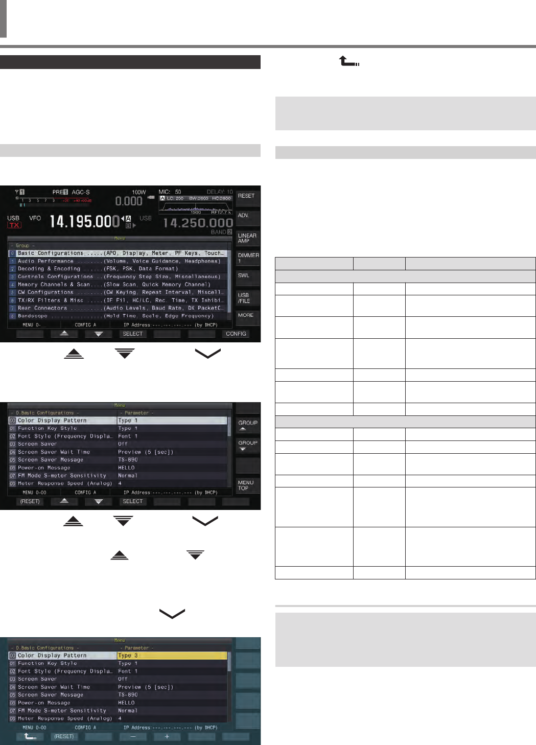
Menu Operation
The settings of the different functions of this transceiver can be
changed from the menu. It can also be used to switch the operating
environment.
There is also a list of frequently used menu items as well as “sub-
menus” that are sorted by function.
Calling Up a Menu
1Press [MENU] to display the menu screen.
.
2Press F2 [ ]/ F3 [ ] or [M.IN]/ [ ] to
select a group.
3Press F4 [SELECT] to display the menu items of the
selected group.
.
4Press F2 [ ]/ F3 [ ] or [M.IN]/ [ ], or turn
the [MULTI/CH] control to select the desired menu
item.
•Pressing F [GROUP ]/ F [GROUP ] changes the
group. (Refer to 3-3 Menu Items.)
•Pressing F [MENU TOP] returns the menu screen to the top.
5Press F4 [SELECT] or [Q-MR>].
The parameter setting can now be changed.
6Press F4 [–]/ F5 [+] or [M.IN]/ [ ], or turn the
[MULTI/CH] control to select the setting value.
.
The setting switches to a different setting.
•To restore the default setting of the selected menu, press
and hold F2 [(RESET)].
7Press F1 [ ] or [<Q-M.IN].
The selected content is confirmed.
8Press [MENU] or [ESC] to exit the menu screen.
In the subsequent descriptions on the menus, the expression
“Configure in Menu [X-XX] ’Xxxx xxxx xxxxx’” will be used.
(Example: Configure in Menu [3-06] “MHz Step”)
Calling Up a Sub-Menu
1Press [MENU] to display the menu screen.
The function keys of the sub-menu are displayed on the right
side of the screen.
2Press F [MORE] to switch between sub-menu
selection 1 and 2.
3Press the desired function key.
The following sub-menus are displayed.
Sub-Menu Key Guide Behavior
Sub-Menu Selection 1
Reset RESET Displays the Reset menu screen.
Advanced ADV. Displays the Advanced Menu
screen.
Linear Amplifier LINEAR
AMP Displays the Linear Amplifier menu
screen.
Dimmer DIMMER
n
Short press: Switches the dimmer.
Long press: Displays the Dimmer
menu screen.
SWL SWL Displays the horizontal dial screen.
USB/File USB
/FILE Displays the USB/File
Management menu screen.
MORE MORE Switches to sub-menu selection 2.
Sub-Menu Selection 2
Clock CLOCK Displays the Clock menu screen.
LAN LAN Displays the LAN menu screen.
Auto Mode AUTO
MODE Displays the Auto Mode menu
screen.
KNS KNS Displays the KNS menu screen.
Timer TIMER
Short press: Switches the paused
state of a timer.
Long press: Displays the Timer
menu screen.
Frequency Marker F.MKR
xxx
Short press: Switches the marker
display.
Long press: Displays the
Frequency Marker menu screen.
MORE MORE Switches to sub-menu selection 1.
Advanced Menu
In the subsequent descriptions on the advanced menus, the
expression “Configure in Advanced Menu [XX] ’Xxxx xxxx
xxxxx’” will be used.
(Example: Configure in Advanced Menu [9] “Antenna Tuner
Operation per Band”)
MENU 3
3 MENU
3-1
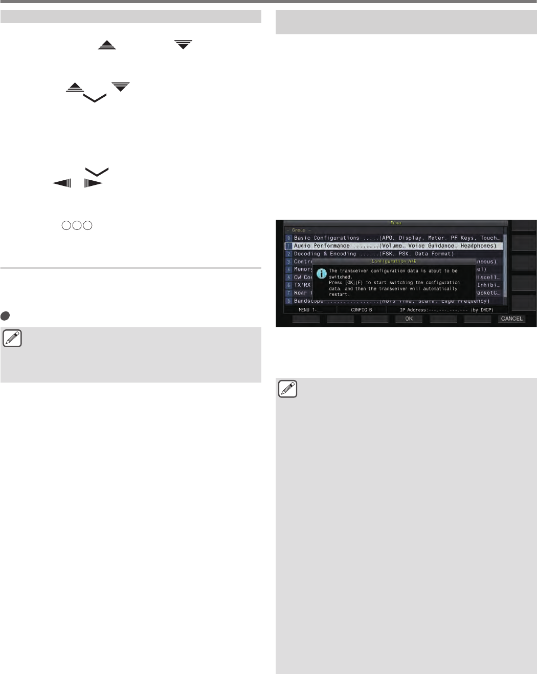
Common Menu Screen Operations
•Pressing F [MENU TOP] returns the menu screen to the top.
•Pressing F [GROUP ]/ F [GROUP ] switches the
group.
•The menu item can be selected in the following ways.
•Turn the [MULTI/CH] control.
•Press F2 [ ]/ F3 [ ].
•Press [M.IN]/ [ ].
•Press [UP] or [DOWN] on the microphone.
•The setting value in the Parameter field can be selected in the
following ways.
•Turn the [MULTI/CH] control.
•Press [UP] or [DOWN] on the microphone.
•Press F4 [–]/ F5 [+].
•Press [M.IN] / [].
•Press [ ]/ [ ].
•Pressing and holding [(RESET)] restores the altered setting
value to the default setting.
•Pressing F [MORE] switches the key guide display.
•Pressing F [ TOP] when configuring the sub-menu
returns the sub-menu screen to the top.
Exiting the Menu
To exit configuration or editing on the menu screen or to end the
configuration of a menu item halfway, follow the steps below. The
menu screen closes and the display returns to the normal screen.
Press [MENU] or [ESC].
●It is possible to reset only the menu settings.
●The menu items or default values may be altered.
●When editing the screen saver message or power-on
message, pressing [MENU] will not exit the menu
screen.
Switching between the CONFIG A and CONFIG B
Operating Environments
“Operating environment” refers collectively to values configured in
the menu as well as the different settings data for operation. Two
different types of operating environment are available on this
transceiver: CONFIG A and CONFIG B. Both CONFIG A and
CONFIG B have the same functions and they can be configured
independently of each other. For example, it is possible to
configure CONFIG A for DX and CONFIG B for rag chew and
switch easily between them.
1Press [MENU] to display the menu screen.
The current operating environment (CONFIG A or CONFIG B)
is displayed in the status bar of the menu screen. Also, data of
the operating environment can be saved to and read from a
transceiver or USB flash drive.
2Press F7 [CONFIG].
A message appears.
•Press F7 [CANCEL] to return to the Menu screen.
.
3Press F4 [OK].
•Switches from CONFIG A to CONFIG B or vice versa, and
this transceiver automatically restarts after switching is
complete.
●The following are common settings between CONFIG A
and B.
•Number of quick memory channels
•Baud rate of COM port
•Baud rate of USB connector (virtual COM port) on the
rear panel
•Decoded character output
●Information and data other than those below are
common between CONFIG A and B.
•Advanced menu settings
•LAN menu settings
•Clock menu settings
•Linear amplifier menu settings
•Timer menu settings
•Memory channel data (including quick memory and
slow scan point data)
•CW/RTTY/PSK message memory data
•Band memory (frequency and mode)
•Broadcast band memory data
•Antenna selection (including drive output selection
and antenna output selection for external receiver)
•Preset data of antenna tuner
•Internal audio file data of recording function (wav file)
•Voice message memory data (wav file)
●If the operating environment is switched while the quick
memory is called up by pressing [Q-MR>] (quick
memory), the quick memory settings will be discarded
before the operating environment switches.
3 MENU
3-2

Menu Items
Menu
- 0. Basic Configurations -
Menu Display Description Setting Value Default Refer to
Display
0-00 Color Display Pattern Display color type Type 1/ Type 2/ Type 3 Type 1 4-1
0-01 Function Key Style Type of function key display Type 1/ Type 2/ Type 3 Type 1 4-1
0-02 Font Style (Frequency Display) Font type (frequency display) Font 1/ Font 2/ Font 3/ Font 4/ Font
5Font 1 4-1
0-03 Screen Saver Screen saver Off/ Type 1/ Type 2/ Type 3/
Display Off Off 16-1
0-04 Screen Saver Wait Time Wait time for screen saver Preview (5 [sec])/ 5/ 15/ 30/ 60 [min] Preview (5
[sec]) 16-1
0-05 Screen Saver Message Screen saver message Up to 10 alphanumeric characters TS-890 16-1
0-06 Power-on Message Power on message Up to 15 alphanumeric characters HELLO 16-1
Meter
0-07 FM Mode S-Meter Sensitivity FM S meter sensitivity Normal/ High Normal 4-9
0-08 Meter Response Speed (Analog) Analog meter response 1 to 4 (1 step) 3 4-9
0-09 Meter Display Pattern Meter type Digital/ Analog (White)/ Analog
(Black) Analog
(White) 4-9
0-10 Meter Display Peak Hold Meter with peak hold Off/ On On 4-9
0-11 S-Meter Scale S meter scale Type 1/ Type 2 Type 1 4-9
0-12 TX Digital Meter TX meter (digital) Off/ On Off 4-9
Key
0-13 Long Press Duration of Panel Keys Duration for pressing and holding
a key 200 to 2000 [ms] (100 [ms] step) 500 [ms] 16-2
0-14 Touchscreen Tuning Touchscreen tuning Off/ On On 7-4
0-15 PF A: Key Assignment Function assignment to [PF A]
key Refer to PF (Programmable
Function). VOICE1 16-2
0-16 PF B: Key Assignment Function assignment to [PF B]
key Refer to PF (Programmable
Function). VOICE2 16-2
0-17 PF C: Key Assignment Function assignment to [PF C]
key Refer to PF (Programmable
Function). VOICE3 16-2
0-18 External PF 1: Key Assignment Function assignment to [PF 1] on
the keypad Refer to PF (Programmable
Function).
Message
Memory CH 1
16-3
0-19 External PF 2: Key Assignment Function assignment to [PF 2] on
the keypad Refer to PF (Programmable
Function).
Message
Memory CH 2
16-3
0-20 External PF 3: Key Assignment Function assignment to [PF 3] on
the keypad
Refer to PF (Programmable Function).
Message
Memory CH
316-3
0-21 External PF 4: Key Assignment Function assignment to [PF 4] on
the keypad Refer to PF (Programmable
Function).
Message
Memory CH 4
16-3
0-22 External PF 5: Key Assignment Function assignment to [PF 5] on
the keypad Refer to PF (Programmable
Function).
Message
Memory CH 5
16-3
0-23 External PF 6: Key Assignment Function assignment to [PF 6] on
the keypad Refer to PF (Programmable
Function).
Message
Memory CH 6
16-3
0-24 External PF 7: Key Assignment Function assignment to [PF7] on
the keypad Refer to PF (Programmable
Function).
Message
Memory CH 7
16-3
0-25 External PF 8: Key Assignment Function assignment to [PF 8] on
the keypad Refer to PF (Programmable
Function).
Message
Memory CH 8
16-3
0-26 Microphone PF 1: Key Assignment Function assignment to [PF 1] on
the microphone Refer to PF (Programmable
Function). A/B, A=B 16-3
MENU 3
3-3

- 0. Basic Configurations -
Menu Display Description Setting Value Default Refer to
Display
0-27 Microphone PF 2: Key Assignment Function assignment to [PF 2] on
the microphone Refer to PF (Programmable
Function). SPLIT 16-2
0-28 Microphone PF 3: Key Assignment Function assignment to [PF 3] on
the microphone Refer to PF (Programmable
Function). M/V, M V16-2
0-29 Microphone PF 4: Key Assignment Function assignment to [PF 4] on
the microphone Refer to PF (Programmable
Function). MONI 16-2
0-30 Microphone DOWN: Key Assignment Function assignment to [DOWN]
on the microphone Refer to PF (Programmable
Function).
DWN Key
(Microphone)
16-2
0-31 Microphone UP: Key Assignment Function assignment to [UP] on
the microphone Refer to PF (Programmable
Function).
UP Key
(Microphone)
16-2
0-32 Automatic Power Off APO (Automatic Power Off) Off/ 60/ 120/ 180 [min] Off 16-2
- 1. Audio Performance -
Menu Display Description Setting Value Default Refer to
Volume
1-00 Beep Volume Volume of beep tone Off/ 1 to 20 (1 step) 10 16-2
1-01 Voice Message Volume (Play) Playback volume of voice
message Off/ 1 to 20 (1 step) 10 12-2
1-02 Sidetone Volume Sidetone volume Off/ 1 to 20 (1 step) 10 5-9
Voice Guide
1-03 Voice Guidance Volume Voice guide volume Off/ 1 to 20 (1 step) 10 13-1
1-04 Voice Guidance Speed Voice guide speed 1 to 4 (1 step) 1 13-1
1-05 User Interface Language (Voice
Guidance & Messages) Language of voice guide and
message display English/ Japanese English 13-1
1-06 Automatic Voice Guidance Automatic voice guide Off/ On Off 13-1
- 2. Decoding & Encoding -
Menu Display Description Setting Value Default Refer to
FSK Decoding
2-00 FFT Scope Averaging (RTTY Decode) Averaging on the FFT scope
(RTTY Decode) 0 to 9 (1 step) 0 5-24
2-01 RX UOS RX unshift-on-space Off/ On On 5-21
2-02 Newline Code New line code selection (during
reception) CR+LF/ All All 5-21
2-03 Diddle Diddle Off/ Blank Code/ Letters Code Blank Code 5-21
2-04 TX UOS TX unshift-on-space Off/ On On 5-21
2-05 Automatic Newline Insertion Automatic new line code insertion On/ Off On 5-21
FSK Key
2-06 FSK Spacing FSK shift width 170/ 200/ 425/ 850 [Hz] 170 [Hz] 5-21
2-07 FSK Keying Polarity FSK keying polarity Off/ On Off 5-21
2-08 FSK Tone Frequency FSK tone frequency 1275/ 2125 [Hz] 2125 [Hz] 5-21
2-09 RTTY Tuning Scope Scope display for checking FSK
tuning FFT Scope/ X-Y Scope FFT Scope 5-18
PSK Decoding
2-10 FFT Scope Averaging (PSK Decode) Averaging on the FFT scope
(PSK Decode) 0 to 9 (1 step) 0 5-18
2-11 PSK AFC Tuning Range Tuning range for PSK AFC ±15/ ±8 [Hz] ±15 [Hz] 5-24
2-12 PSK Tone Frequency PSK tone frequency 1.0/ 1.5/ 2.0 [kHz] 1.5 [kHz] 5-27
2-13 PSK Tuning Scope Scope display for checking PSK
tuning FFT Scope/ X-Y Scope FFT Scope 5-18
Common
2-14 CW/ RTTY/ PSK Log File Format File format for saving CW/RTTY/
PSK logs html/ txt txt 5-27
2-15 CW/ RTTY/ PSK Time Stamp CW/ RTTY/ PSK time stamp Off/ Time Stamp/ Time Stamp +
Frequency Time Stamp
+ Frequency 5-27
2-16 Clock (CW/ RTTY/ PSK Time Stamp) Clock selection for CW/ RTTY/
PSK time stamp Local Clock/ Secondary Clock Local Clock 5-27
2-17 Waterfall when Tuning (RTTY/ PSK
Audio Scope) Selection of RTTY/ PSK waterfall
display type Straight/ Follow Straight 5-19
5-24
3 MENU
3-4

- 3. Controls Configurations -
Menu Display Description Setting Value Default Refer to
Control Rate
3-00 Frequency Rounding Off (Multi/ Channel
Control) Rounds off the frequency of the
[MULTI/CH] control Off/ On On 4-6
3-01 SSB Mode Frequency Step Size (Multi/
Channel Control) SSB frequency step size 0.5/ 1/ 2.5/ 5/ 10 [kHz] 1 [kHz] 4-6
3-02 CW/FSK/PSK Mode Frequency Step
Size (Multi/Channel Control) CW/ FSK/ PSK frequency step
size 0.5/ 1/ 2.5/ 5/ 10 [kHz] 0.5 [kHz] 4-6
3-03 FM Mode Frequency Step Size (Multi/
Channel Control) FM frequency step size 5/ 6.25/ 10/ 12.5/ 15/ 20/ 25/ 30/ 50/
100 [kHz] 10 [kHz] 4-6
3-04 AM Mode Frequency Step Size (Multi/
Channel Control) AM frequency step size 5/ 6.25/ 10/ 12.5/ 15/ 20/ 25/ 30/ 50/
100 [kHz] 5 [kHz] 4-6
3-05 9 kHz Step in AM Broadcast Band (Multi/
Channel Control) Steps of the [MULTI/CH] control
in the BC band (AM) Off/ On K type: Off
E type: On 4-6
3-06 MHz Step MHz step 100/ 500/ 1000 [kHz] 1000 [kHz] 4-6
3-07 Tuning Control: Number of Steps per
Revolution Number of steps per revolution of
the Tuning control 250/ 500/ 1000 [Step] 1000 [Step] 4-6
3-08 Tuning Speed Control Fast forward rate of the Tuning
control Off/ 2 to 10 (1 step) Off 4-6
3-09 Tuning Speed Control Sensitivity Sensitivity of the Tuning control
for starting the fast forward
operation 1 to 10 (1 step) 5 4-6
3-10 Lock Function Frequency lock function Frequency Lock/ Tuning Control
Lock Frequency
Lock 4-6
3-11 Number of Band Memories Number of band memories 1/ 3/ 5 3 4-3
3-12 Split Frequency Offset by RIT/XIT
Control Changing the split frequency
using the [RIT/XIT] control
Off/ TX Frequency Offset while RX/
RX Frequency Offset while TX/
Both Off 5-1
3-13 Band Direct Keys in Split Mode Band direct key during split
operation RX Band/ RX Band and Cancel
Split Mode/ RX/ TX Band RX Band 5-1
- 4. Memory Channels & Scan -
Menu Display Description Setting Value Default Refer to
Memory
4-00 Number of Quick Memory Channels Number of quick memory
channels 3/ 5/ 10 [ch] 5 [ch] 9-5
4-01 Temporary Change (Memory Channel
Configurations) Temporary change of memory
frequency Off/ On Off 9-3
Scan
4-02 Program Slow Scan Program slow scan Off/ On On 10-2
4-03 Program Slow Scan Range Range of program slow scan 100/ 200/ 300/ 400/ 500 [Hz] 300 [Hz] 10-3
4-04 Scan Hold Scan Hold Off/ On Off 10-3
4-05 Scan Resume Scan resume condition Time-operated/ Carrier-operated Time-
operated 10-4
- 5. CW Configurations -
Menu Display Description Setting Value Default Refer to
Jack Terminals
5-00 Paddle Jack Configuration (Front) PADDLE jack (front panel)
function setting Straight Key/ Paddle/ Paddle (Bug
Key Mode) Paddle 5-13
5-01 Key Jack Configuration (Rear) KEY jack (rear panel) function
setting Straight Key/ Paddle/ Paddle (Bug
Key Mode) Straight Key 5-13
Mode
5-02 Electronic Keyer Squeeze Mode Operation mode of the electronic
keyer Mode A/ Mode B Mode B 5-13
5-03 Dot and Dash Reversed Keying Switches between dot and dash
paddle Off/ On Off 5-13
5-04 Paddle (Microphone Up/Down Keys) Paddle ([UP] and [DOWN] keys
on microphone) Off/ On Off 5-13
5-05 CW BFO Side Band CW BFO sideband USB/ LSB USB 5-9
MENU 3
3-5

- 5. CW Configurations -
Menu Display Description Setting Value Default Refer to
Weight and Timing
5-06 Automatic CW TX with Keying in SSB
Mode CW transmission by keying in the
SSB mode Off/ On Off 5-9
5-07 Carrier Frequency Offset (SSB Mode to
CW Mode)
Carrier frequency correction
when shifting from the SSB mode
to CW mode Off/ On Off 5-9
5-08 CW Keying Weight Ratio Keyer weight Automatic/ 2.5 to 4.0 (0.1 step) Automatic 5-13
5-09 CW Keying Reversed Weight Ratio Reverse keying auto weight ratio Off/ On Off 5-13
5-10 Interrupt Keying Insert keying Off/ On Off 5-17
Memory
5-11 CW Message Entry Method for registering CW
message Text String/ Paddle Paddle 5-14
5-12 Contest Number Contest number 001 to 9999 (1 step) 001 5-15
5-13 Contest Number Format Contest number style Off/ 190 to ANO/ 190 to ANT/ 90 to
NO/ 90 to NT Off 5-15
5-14 Channel Number (Count-up Message) Specifies the channel used for the
count-up message Off/ Channel 1 to Channel 8 Off 5-15
5-15 CW Rise Time CW rise time 1/ 2/ 4/ 6 [ms] 6 [ms] 5-9
5-16 CW/ Voice Message Retransmit Interval
Time Repeat interval for retransmitting
CW/voice message 0 to 60 [s] (1 [s] step) 10 [s] 5-17
12-2
- 6. TX/RX Filter & Misc. -
Menu Display Description Setting Value Default Refer to
Message
6-00 Playback Time (Full-time Recording) Playback time for constantly
recorded audio Last 10/ Last 20/ Last 30 [s] Last 30 [s] 12-3
6-01 Recording with Squelch Audio recording in tandem with
squelch Off/ On On 12-3
TX Management
6-02 Time-out Timer Maximum continuous
transmission time (Timeout timer) Off/ 3/ 5/ 10/ 20/ 30 [min] Off 8-8
6-03 TX Inhibit Inhibits transmission Off/ On Off 16-11
6-04 Transmit Power Step Size Fine adjustment of TX output
power 1/ 5 [W] 5 [W] 4-8
6-05 ID Beep ID beep Off/ 1 to 30 [min] (1 step) Off 8-8
Filter
6-06 TX Filter Low Cut (SSB/AM) Low-cut frequency of the TX filter
(SSB/AM) 10/ 100/ 200/ 300/ 400/ 500 [Hz] 100 [Hz] 8-5
6-07 TX Filter High Cut (SSB/AM) High-cut frequency of the TX filter
(SSB/AM) 2500/ 2600/ 2700/ 2800/ 2900/
3000/ 3500/ 4000 [Hz] 2900 [Hz] 8-5
6-08 TX Filter Low Cut (SSB-DATA/AM-
DATA) Low-cut frequency of the TX filter
(SSB-DATA/AM-DATA) 10/ 100/ 200/ 300/ 400/ 500 [Hz] 100 [Hz] 8-5
6-09 TX Filter High Cut (SSB-DATA/AM-
DATA) High-cut frequency of the TX filter
(SSB-DATA/AM-DATA) 2500/ 2600/ 2700/ 2800/ 2900/
3000/ 3500/ 4000 [Hz] 2900 [Hz] 8-5
6-10 RX Filter Numbers Number of RX filters 2/ 3 3 6-1
6-11 Filter Control in SSB Mode (High/Low
and Shift/Width) Switches between High-cut/low-
cut and WIDTH/SHIFT (SSB) High & Low Cut/ Shift & Width High & Low
Cut 6-2
6-12 Filter Control in SSB-DATA Mode
(High/Low and Shift/Width)
Switches between High-cut/low-
cut and WIDTH/SHIFT (SSB-
DATA) High & Low Cut/ Shift & Width Shift & Width 6-2
6-13 VOX Voice Delay (Microphone) Audio delay in the VOX mode
(MIC) Off/ Short/ Middle/ Long Middle 8-2
6-14 VOX Voice Delay (Except Microphone) Audio delay in the VOX mode
(excluding MIC) Off/ Short/ Middle/ Long Middle 8-2
6-15 Delta Frequency Display ⊿F display setting Off/ On On 5-1
3 MENU
3-6

- 7. Rear Connectors -
Menu Display Description Setting Value Default Refer to
Baud Rate
7-00 Baud Rate (COM Port) Baud rate of COM connector 4800/ 9600/ 19200/ 38400/ 57600/
115200 [bps] 9600 [bps] 16-5
7-01 Baud Rate (Virtual Standard COM) Baud rate of virtual COM
(Standard) connector 9600/ 19200/ 38400/ 57600/
115200 [bps] 115200 [bps] 16-5
7-02 Baud Rate (Virtual Enhanced COM) Baud rate of virtual COM
(Enhanced) connector 9600/ 19200/ 38400/ 57600/
115200 [bps] 115200 [bps] 16-12
7-03 Decoded Character Output Decoded character output Off/ On Off 16-12
Data transfer
7-04 Quick Data Transfer Quick data transfer Off/ 1 (TX/RX)/ 1 (Sub RX)/ 2 Off 16-9
7-05 Overwrite Location (Quick Data Transfer) Destination for data via quick data
transfer VFO/ Quick Memory Quick
Memory 16-9
Audio input
7-06 USB: Audio Input Level USB audio input level 0 to 100 (1 step) 50 16-7
7-07 ACC 2: Audio Input Level Audio input level of ACC 2
connector 0 to 100 (1 step) 50 16-7
Audio output
7-08 USB: Audio Output Level USB audio output level 0 to 100 (1 step) 100 16-7
7-09 ACC 2: Audio Output Level Audio output level from ACC 2
connector 0 to 100 (1 step) 50 16-7
7-10 TX Monitor Level (Rear Connectors) TX monitor level output to the rear
panel connector Linked/ 0 to 20 (1 step) Linked 16-7
7-11 Audio Output Type (Rear Connectors) Format of audio output from the
rear panel connector All/ Received Audio only All 16-7
- 8. Bandscope -
Menu Display Description Setting Value Default Refer to
Common
8-00 Bandscope Display during TX Bandscope display during
transmission Off/ On Off 7-6
8-01 TX Audio Waveform Display Waveform display for transmitted
audio On/ Off On 8-4
8-02 Bandscope Maximum Hold Maximum hold time 10 [s]/ Continuous 10 [s] 7-5
8-03 Waterfall when Tuning (Center Mode) Waterfall display during tuning
(center mode) Straight/ Follow Straight 7-2
8-04 Waterfall Gradation Level Gradation setting of the waterfall 1 to 10 (1 step) 7 7-4
8-05 Tuning Assist Line (SSB Mode) Auxiliary tuning line display (SSB
only) Off/ 300/ 400/ 500/ 600/ 700/ 800/
1000/ 1500/ 2210 [Hz] Off 7-4
8-06 Frequency Scale (Center Mode) Frequency scale in the center
mode Relative Frequency/ Absolute
Frequency Relative
Frequency 7-2
8-07 Touchscreen Tuning Step Correction
(SSB/ CW/ FSK/ PSK) Correction steps for touchscreen
tuning Off/ On On 7-5
- 9. USB Keyboard -
Menu Display Description Setting Value Default Refer to
USB keyboard
9-00 Send Message by Function Keys Function key settings of USB
keyboard Off/ On On 16-5
9-01 Keyboard Language USB keyboard language
Japanese/ English (US)/ English
(UK)/ French/ French (Canadian)/
German/ Portuguese/ Portuguese
(Brazilian)/ Spanish/ Spanish
(Latin American)/ Italian
English (US) 16-5
9-02 Repeat Delay Time Key repeat delay time for USB
keyboard 1 to 4 (1 step) 2 16-5
9-03 Repeat Speed Key repeat speed for USB
keyboard 1 to 32 (1 step) 1 16-5
MENU 3
3-7

Advanced Menu Items
Menu Display Description Setting Value Default Refer to
0Indication Signal Type (External
Meter 1) Target of external meter output 1 Automatic/ TX Power/ ALC/ Drain
Voltage (Vd)/ Compression Level
(COMP)/ Current (Id)/ SWR TX Power 16-6
1Indication Signal Type (External
Meter 2) Target of external meter output 2 Automatic/ TX Power/ ALC/ Drain
Voltage (Vd)/ Compression Level
(COMP)/ Current (Id)/ SWR Automatic 16-6
2 Output Level (External Meter 1) Level of external meter output 1 0 to 100 [%] (1 step) 50 [%] 16-6
3 Output Level (External Meter 2) Level of external meter output 2 0 to 100 [%] (1 step) 50 [%] 16-6
4 Reference Signal Source Switches the reference signal Internal/ External Internal 16-8
5Reference Oscillator
Calibration Adjusts the frequency of the reference
oscillator -500 to +500 (1 step) 0 17-2
6TX Power Down with
Transverter Enabled Powers down the transverter function Off/ On On 16-15
7 TX Hold After Antenna Tuning Holds transmission at the end of antenna
tuning Off/ On Off 4-11
8 Antenna Tuner during RX Antenna tuner behavior while receiving Off/ On Off 4-12
9Antenna Tuner Operation per
Band Antenna tuner behavior for each band Off/ On Off 4-12
10 Microphone Gain (FM Mode) FM microphone gain 0 to 100 (1 step) 50 5-28
11 PKS Polarity Reverse Reversing of PSK polarity Off/ On Off 16-12
12 TX Inhibit While Busy Inhibits transmission while in the BUSY
state Off/ On Off 16-12
13 CTCSS Unmute for Internal
Speaker Mute behavior of CTCSS Mute/ Unmute Mute 16-8
14 PSQ Logic State SQL control signal logic Low/ Open Low 16-8
15 PSQ Reverse Condition SQL output conditions Off/ Busy/ Sql/ Send/ Busy-Send/
Sql-Send Sql 16-8
16 PSQ/ PKS Pin Assignment
(COM Connector) PSQ/PKS mode setting Off/ On Off 16-8
17 Virtual Standard COM Port -
RTS RTS settings of virtual COM port
(Standard) Flow Control/ CW Keying/ RTTY
Keying/ PTT/ DATA SEND Flow Control 16-12
18 Virtual Standard COM Port -
DTR DTR settings of virtual COM port
(Standard) Off/ CW Keying/ RTTY Keying/
PTT/ DATA SEND Off 16-12
19 Virtual Enhanced COM Port -
RTS RTS settings of virtual COM port
(Standard) Off/ CW Keying/ RTTY Keying/
PTT/ DATA SEND Off 16-12
20 Virtual Enhanced COM Port -
DTR RTS settings of virtual COM port
(Standard) Off/ CW Keying/ RTTY Keying/
PTT/ DATA SEND Off 16-12
21 External Display External display output Off/ On On 16-7
22 Resolution (External Display) Resolution settings of external display 800 x 600/ 848 x 480 800 x 600 16-7
23 Touchscreen Calibration Touchscreen adjustment – – 17-3
24 Software License Agreement Software license of this transceiver – – i
25 Important Notices concerning
Free Open Source Ways to obtain open source resources
used by this transceiver – – ii
26 About Various Software
License Agreements Licenses related to software used by this
transceiver – – ii
27 Firmware Version Firmware version used by this
transceiver – – 17-1
Reset Menu Items
Display Description Refer to
Menu Reset Menu reset
17-1
Memory Channel Reset Memory channel reset
VFO Reset VFO reset
Standard Reset (The Clock, TX Inhibit, and
Transmit Power Upper Limit will not be reset) Standard reset
Full Reset Full reset
3 MENU
3-8

Linear Amplifier Menu Items
Display Description Setting Value Default Refer to
Band Target bands of the linear amplifier menu HF/ 50M/ 70M (E type) HF
16-14
Linear Amplifier Linear amplifier ON/OFF Off/ On Off
Keying Logic Linear amplifier TX control Active Low/ Active High Active Low
TX Delay Linear amplifier TX delay ON/OFF Off/ On Off
TX Delay Time (CW/FSK/PSK) Linear amplifier TX delay time (CW/FSK/
PSK) 5/ 10/ 15/ 20/ 25/ 30/ 35/ 40
[ms] 15 [ms]
TX Delay Time (SSB/FM/AM) Linear amplifier TX delay time
(SSB/FM/AM) 5/ 10/ 15/ 20/ 25/ 30/ 35/ 40/
45/ 50 [ms] 35 [ms]
Internal Relay Control Linear amplifier relay control Off/ On Off
External ALC Voltage Linear amplifier external ALC voltage -1/ -2/ -3/ -4/ -5/ -6/ -7/ -8/ -9/
-10/ -11/ -12 [V] -4 [V]
Dimmer Menu Items
Dimmer Display Description Setting Value Default Refer to
1Display Screen brightness 5 to 100 (5-step) 100
4-2
LED LED brightness 5 to 100 (5-step) 100
2Display Screen brightness 5 to 100 (5-step) 75
LED LED brightness 5 to 100 (5-step) 75
3Display Screen brightness 5 to 100 (5-step) 50
LED LED brightness 5 to 100 (5-step) 50
4Display Screen brightness 0 to 100 (5-step) 25
LED LED brightness 5 to 100 (5-step) 25
USB/File Management Menu Items
Display Description Setting Value Default Refer to
Safe Removal of USB Flash Drive Removes the USB flash drive safely – – 11-6
Read Configuration Data Reads transceiver settings data – – 11-3
Save Configuration Data Saves transceiver settings data – – 11-2
Copy Files to PC (via USB cable) Copies files to PC (via USB cable) – – 11-4
Copy Files to USB Flash Drive Copies files to USB flash drive – – 11-5
Read Image Files for Screen Saver (Type 3) Reads images for screen saver – – 16-1
Delete Files (Internal Memory) Deletes files stored in the internal
memory of the transceiver – – 11-5
File Storage Location Configures the destination for saving files Internal Memory/ USB Flash
Drive Internal Memory 11-2
Format USB Flash Drive USD flash drive format – – 11-5
MENU 3
3-9
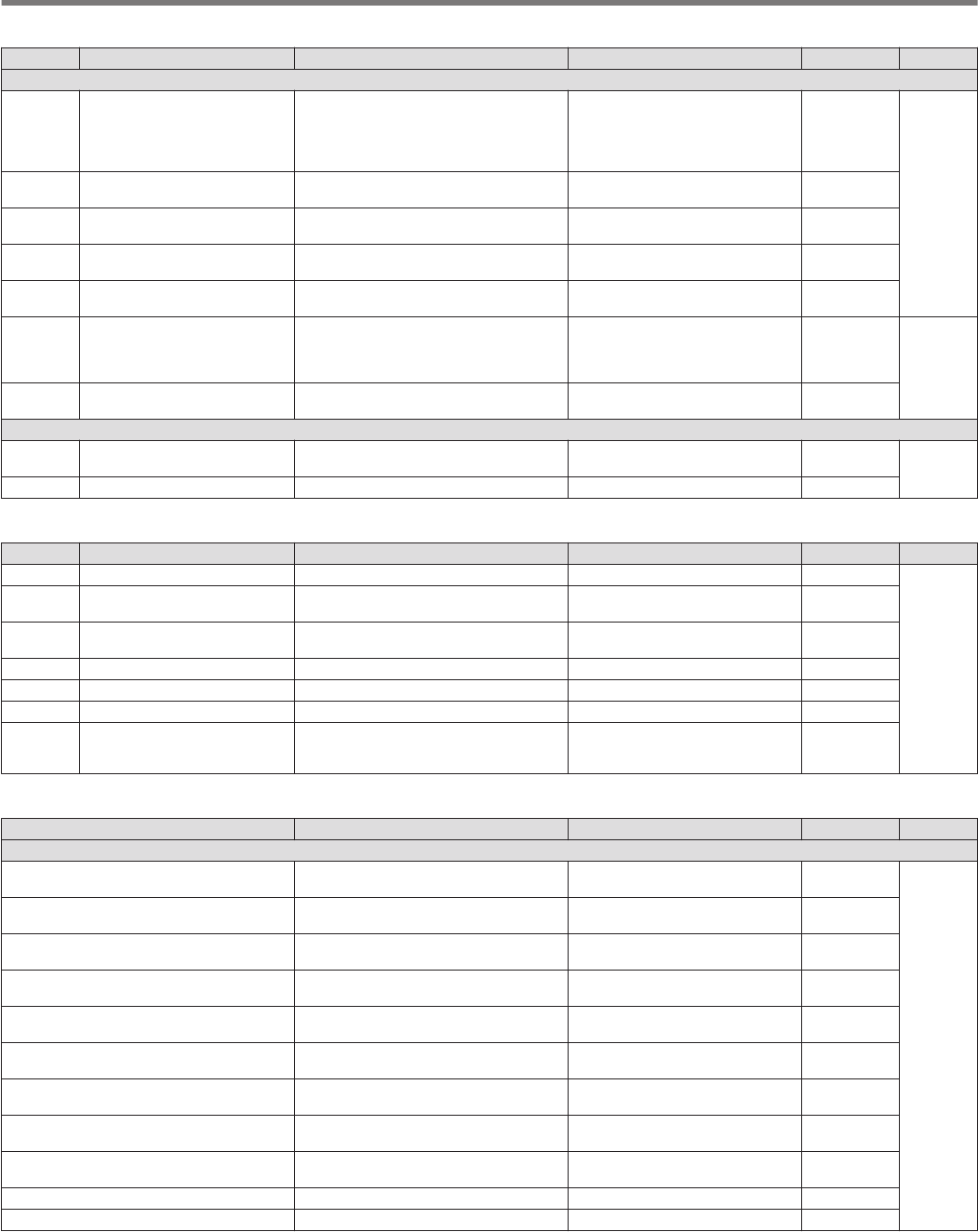
Clock Menu Items
Menu Display Description Setting Value Default Refer to
0.Date and Time
0-00 Date (Local Clock) Date of the local clock
Year: '18 (2018) to '99 (2099)
Month: JAN/ FEB/ MAR/ APR/
MAY/ JUN/ JUL/ AUG/ SEP/ OCT/
NOV/ DEC
Day: 01 to 31
Year: '18
Month: JAN
Day: 01
14-1
0-01 Time (Local Clock) Time of the local clock 00:00 to 23:59 (hour: 00 to 23,
minute: 00 to 59) 00:00
0-02 Timezone (Local Clock) Time zone of the local clock UTC -14:00 to UTC ±00:00 to UTC
+14:00 (15-minute step) UTC +00:00
0-03 Timezone (Secondary Clock) Time zone of the auxiliary clock UTC -14:00 to UTC ±00:00 to UTC
+14:00 (15-minute step) UTC +00:00
0-04 Secondary Clock Identification
Letter Auxiliary clock identifier Single character (A to Z) U
0-05 Date Display Format Date display format MMM/DD/'YY, DD/MMM/'YY, 'YY/
MMM/ DD
K type: MMM/
DD/'YY
E type: DD/
MMM/'YY
14-2
0-06 Clock Display Clock display setting Off/ Local Clock/ Secondary Clock/
Both Both
1.Automatic Time Correction
1-00 Clock Correction using the NTP
Server Automatic clock setting (NTP) Off/ On Off 14-3
1-01 NTP Server Address NTP server address Up to 50 alphanumeric characters Blank
LAN Menu Items
Menu Display Description Setting Value Default Refer to
0 DHCP DHCP Off/ On On
15-1
1 IP Address IP address 1.0.0.0 to 223.255.255.255 192.168.1.
100
2 Subnet Mask Subnet mask 0.0.0.0 to 255.255.255.252 255.255.255.
0
3 Default Gateway Default gateway 1.0.0.0 to 223.255.255.255 Blank
4 Primary DNS Server Primary DNS server 1.0.0.0 to 223.255.255.255 Blank
5 Secondary DNS Server Secondary DNS server 1.0.0.0 to 223.255.255.255 Blank
6 MAC Address MAC address – Fixed value
for each
transceiver
Timer Menu Items
Display Description Setting Value Default Refer to
Programmable Timer
Timer Mode Type of program timer behavior Off/ Power-on/ Power-off/ Power-
on/ off/ Record Off
14-3
Repeat Repeat setting for program timer
behavior Off/ On Off
Day of the Week - Sun Day of week setting for activating
program timer - Sun Check/ Uncheck Check
Day of the Week - Mon Day of week setting for activating
program timer - Mon Check/ Uncheck Check
Day of the Week - Tue Day of week setting for activating
program timer - Tue Check/ Uncheck Check
Day of the Week - Wed Day of week setting for activating
program timer - Wed Check/ Uncheck Check
Day of the Week - Thu Day of week setting for activating
program timer - Thu Check/ Uncheck Check
Day of the Week - Fri Day of week setting for activating
program timer - Fri Check/ Uncheck Check
Day of the Week - Sat Day of week setting for activating
program timer - Sat Check/ Uncheck Check
Power-on Time Program timer operation time start 00:00 to 23:59 00:00
Power-off Time Program timer operation time end 00:00 to 23:59 00:00
3 MENU
3-10
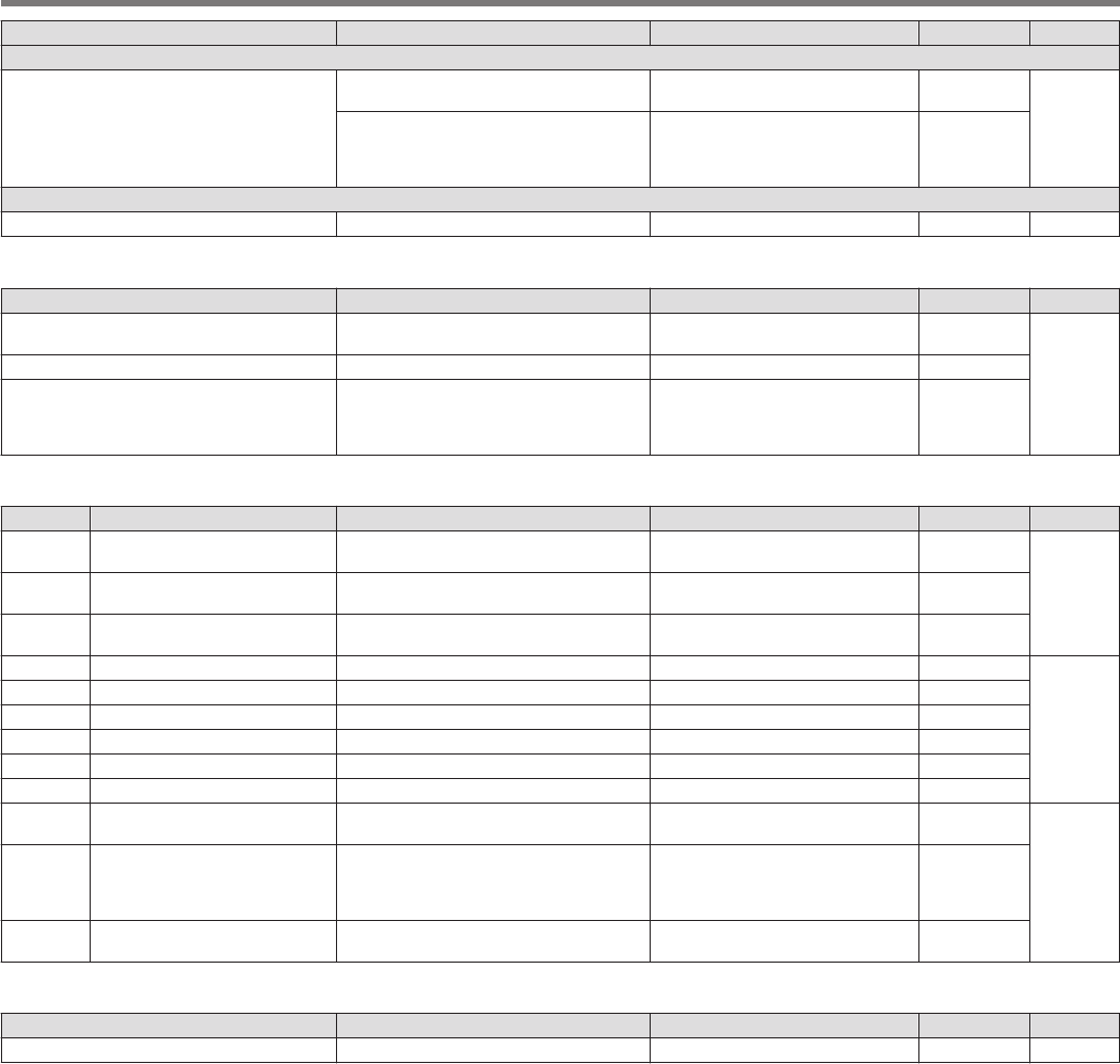
Display Description Setting Value Default Refer to
Programmable Timer
Frequency/Mode
Frequency during program timer
operation 30.000 kHz to 59.999.999 MHz 14.000.000
14-3
Mode during program timer operation
LSB/ USB/ CW/ CW-R/ PSK/ PSK-
R/ FSK/ FSK-R/ FM/ AM/ LSB-
DATA/ USB-DATA/ FM-DATA/
AM-DATA
USB
Sleep Timer
Sleep Timer Sleep timer Off/ 5/ 10/ 15/ 30/ 60/ 90/ 120 [min] Off 14-5
Auto Mode Menu Items
Display Description Setting Value Default Refer to
Auto Mode Auto mode ON/OFF status Auto Mode Off/ Auto Mode On Auto Mode
Off
4-4
Frequency Frequency category of auto mode (#0) 30.000 kHz to 59.999990 MHz 9.5 MHz
Mode Mode of auto mode (#0)
LSB/ USB/ CW/ CW-R/ PSK/ PSK-
R/ FSK/ FSK-R/ FM/ AM/ LSB-
DATA/ USB-DATA/ FM-DATA/
AM-DATA
LSB
KNS Menu Items
Menu Display Description Setting Value Default Refer to
0KNS Operation (LAN
Connector) KNS operation (LAN connection) Off/ On (LAN)/ On (Internet) Off
15-31 Administrator ID KNS administrator ID 1 to maximum 32 alphanumeric
characters Blank
2 Administrator Password KNS administrator password 1 to maximum 32 alphanumeric
characters Blank
3 Built-in VoIP Built-in VoIP function Off/ On On
15-4
4 Audio Input Level (VoIP) VoIP outgoing audio input level 0 to 100 (1 step) 50
5 Audio Output Level (VoIP) VoIP incoming audio output level 0 to 100 (1 step) 100
6 VoIP Jitter Buffer VoIP jitter absorption buffer 200/ 500/ 800 [ms] 200 [ms]
7 Prohibit AF Gain Control Prohibits volume control Off/ On Off
8 Access Log Log function Off/ On Off
9Registered Users' Remote
Operation Remote operation by registered user Off/ On Off
15-610 Session Time Session time
1 [min]/ 2 [min]/ 3 [min]/ 5 [min]/ 10
[min]/ 15 [min]/ 20 [min]/ 30 [min]/
40 [min]/ 50 [min]/ 60 [min]/ 90
[min]/ 120 [min]/ Unlimited
Unlimited
11 KNS Welcome Message KNS welcome message Up to 128 single-byte
alphanumeric characters Blank
Frequency Marker Menu Items
Display Description Setting Value Default Refer to
Frequency Marker frequency (#0 to 49) 30.000 kHz to 59.999.999 MHz – 7-5
MENU 3
3-11

.
3-12