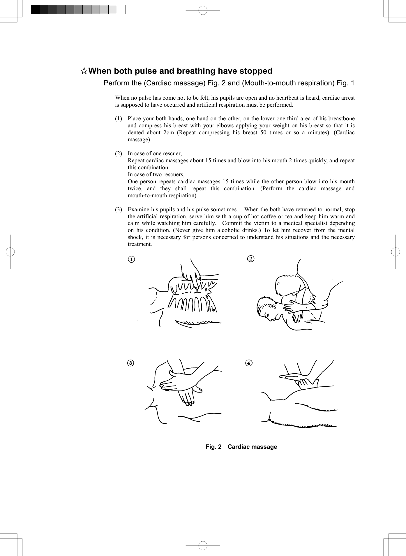
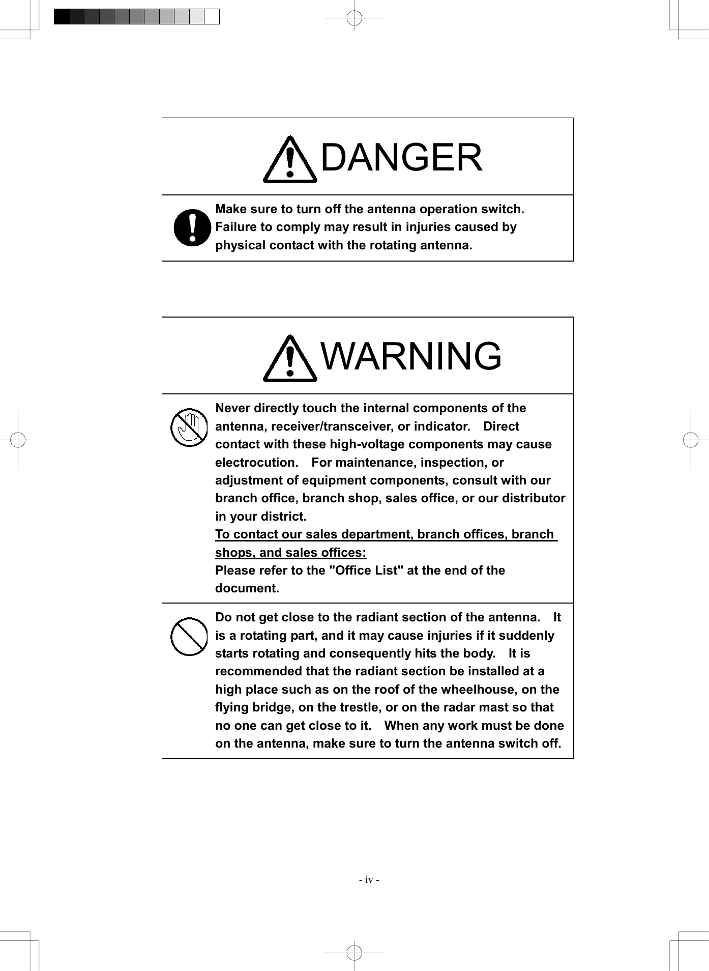
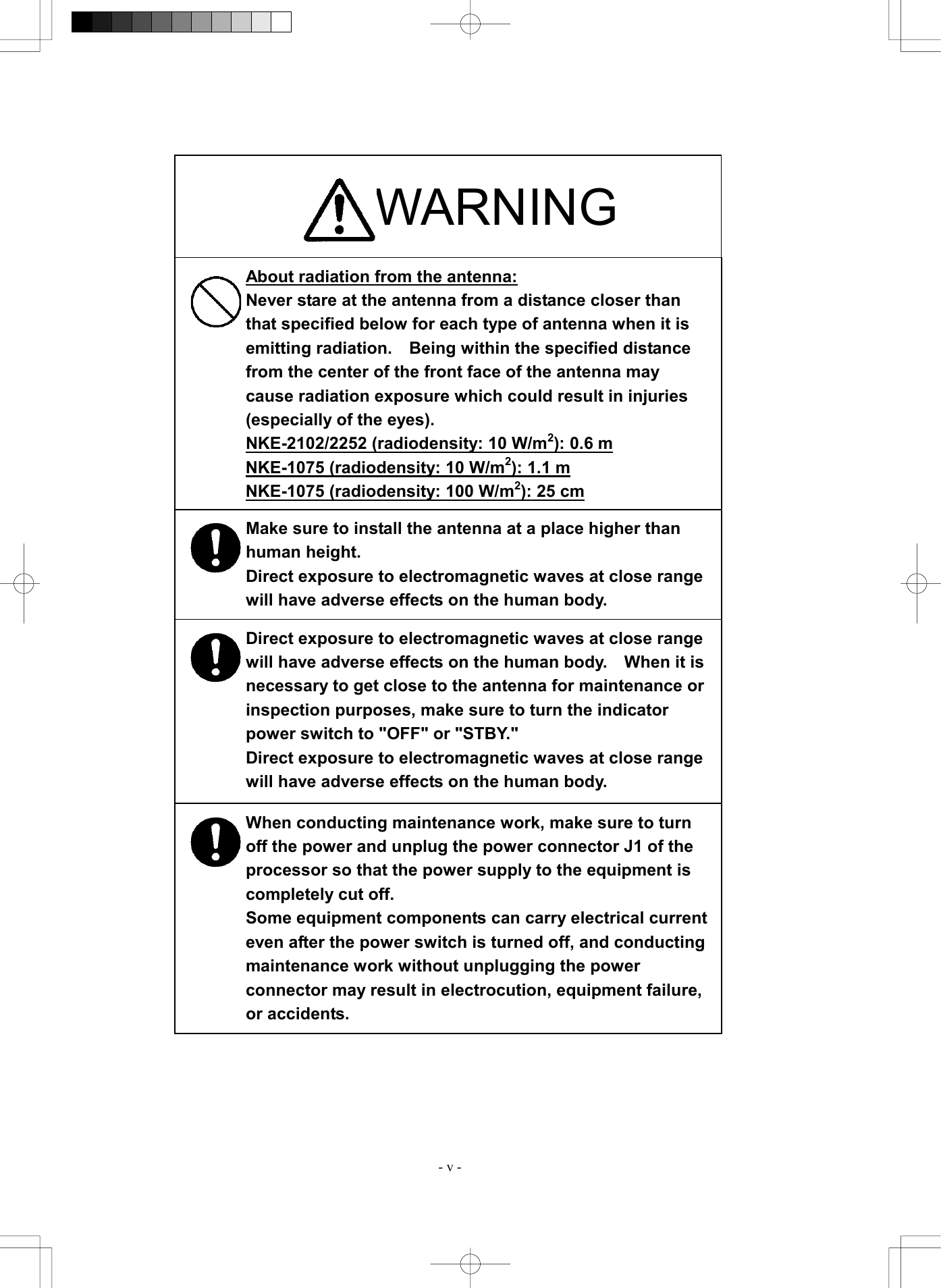
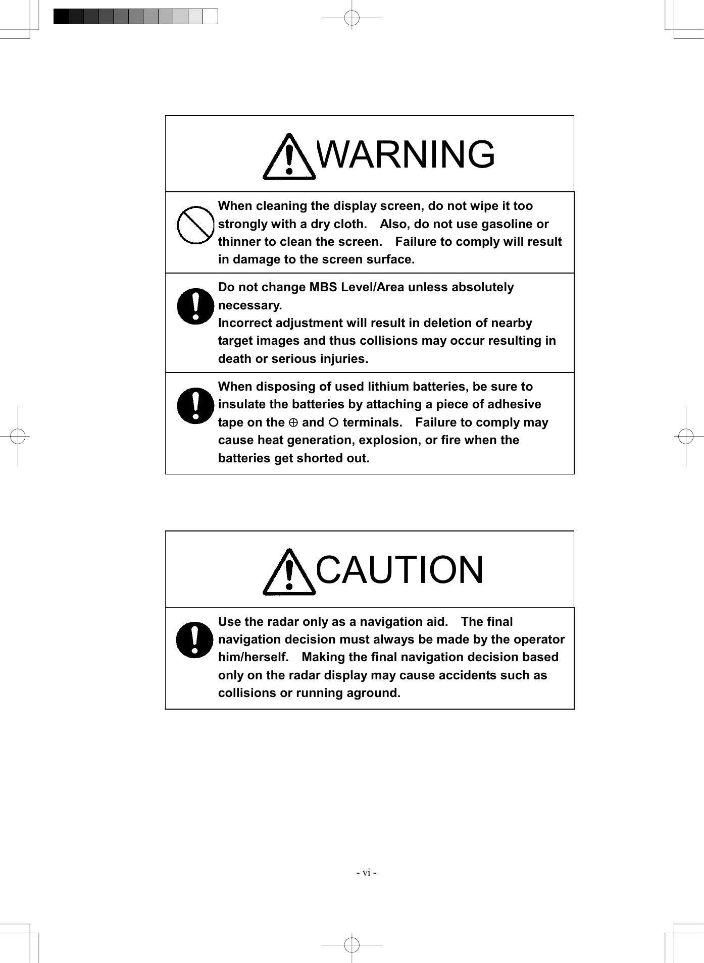
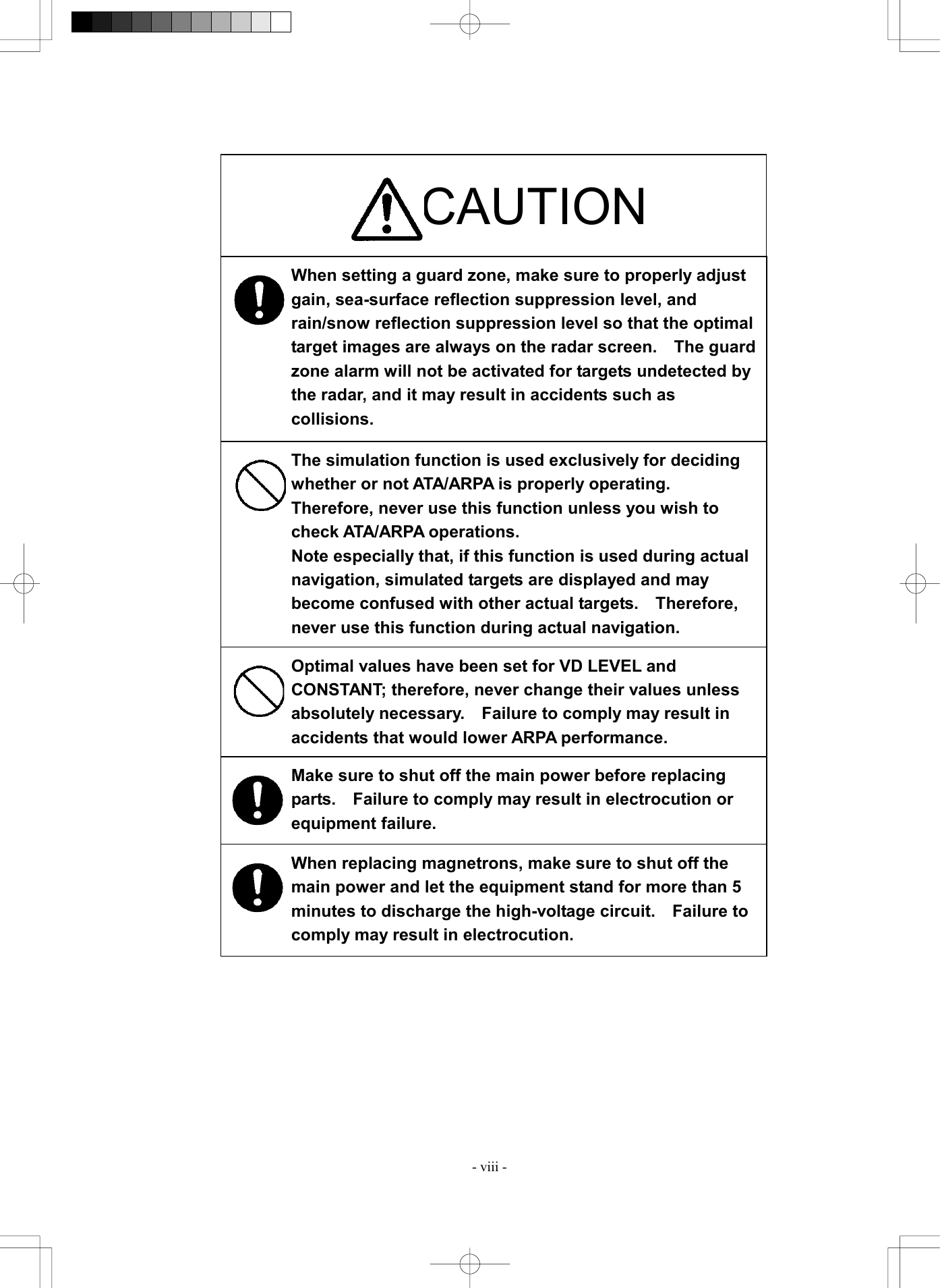
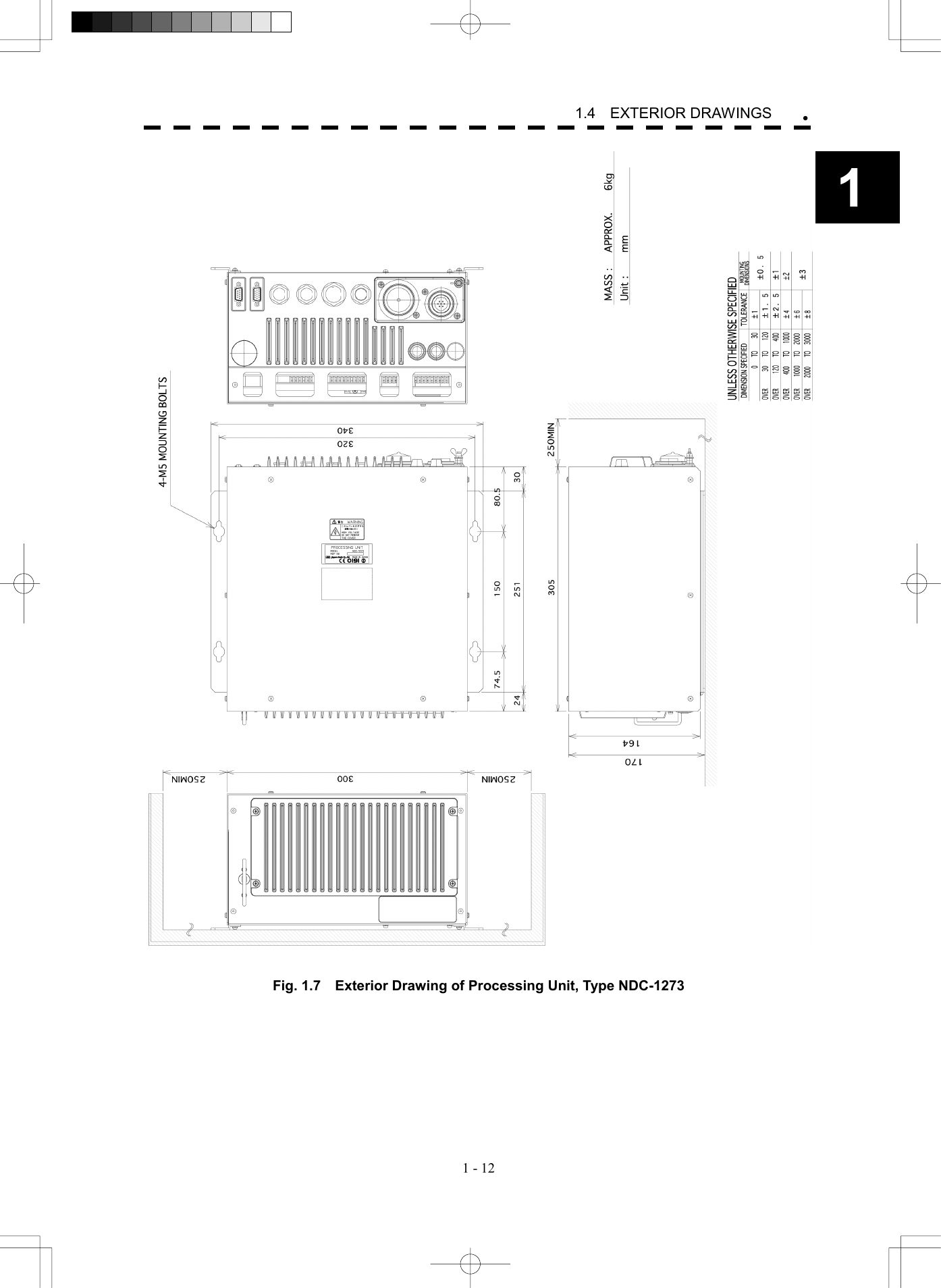
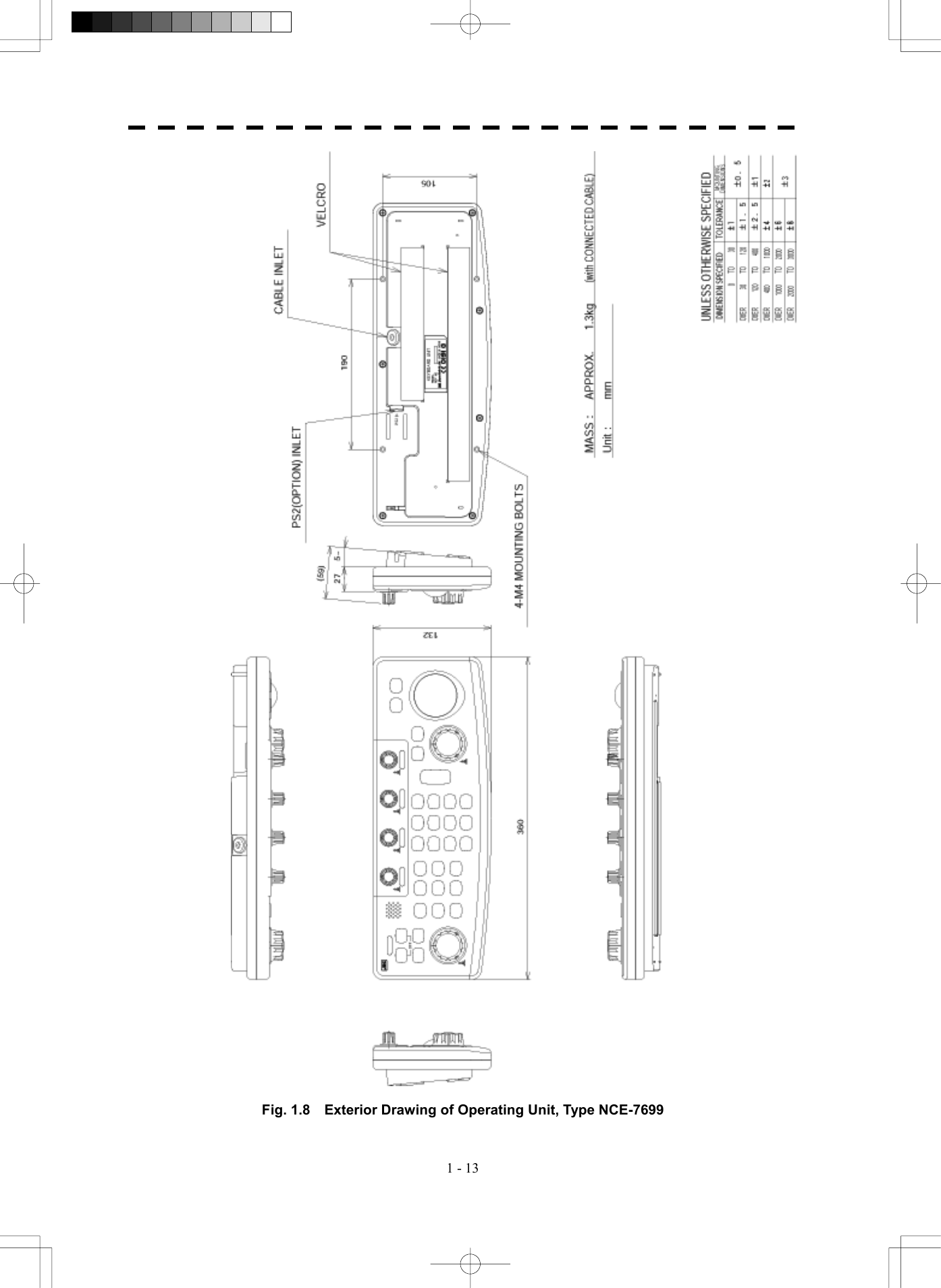
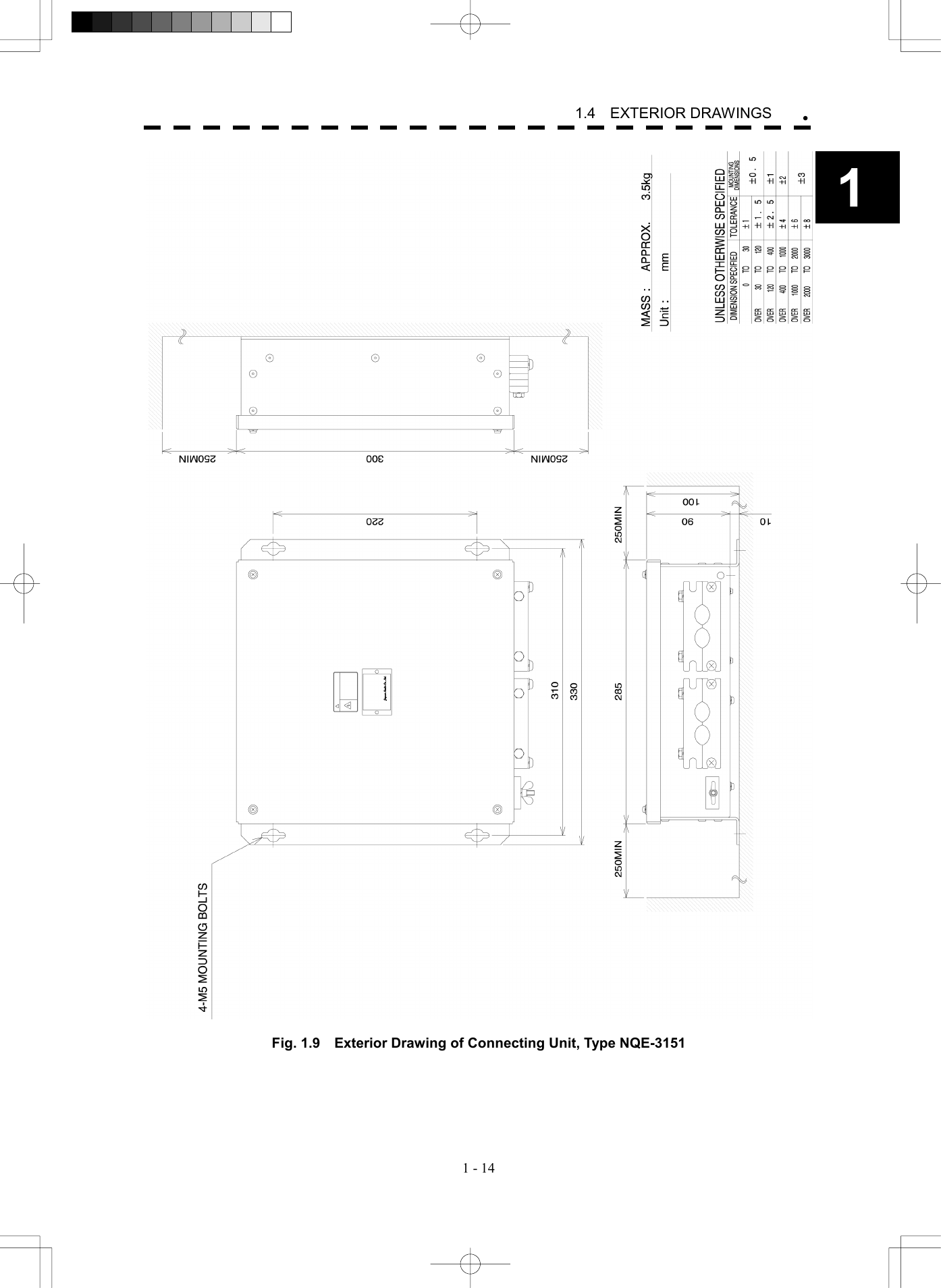
Japan Radio NKE2252 25KW X-Band Radar Transceiver User Manual
Japan Radio Co Ltd. 25KW X-Band Radar Transceiver
UserManual.wiki
>
Japan Radio
>
NKE2252 User Manual
>
Instruction manual 1 of 3
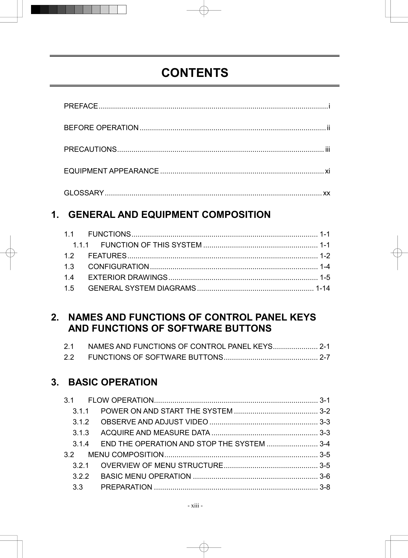
Contents
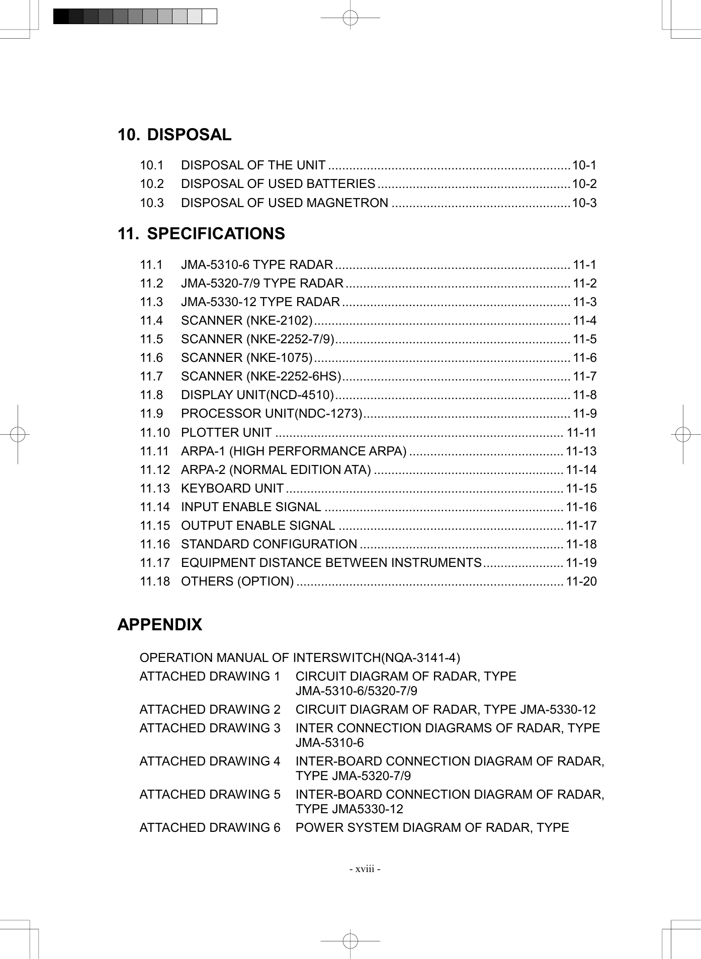
1.
Instruction manual 1 of 3
2.
Instruction manual 2 of 3
3.
Instruction manual 3 of 3
Instruction manual 1 of 3
Navigation menu
Upload a User Manual
Namespaces
Wiki Guide
HTML
PDF
Info
Views
User Manual
Discussion / Help
Navigation
![- vii - CAUTION Use ATA only as a navigation aid. The final navigation decision must always be made by the operator him/herself. Making the final navigation decision based only on ATA information may cause accidents. ARPA information such as vector, target numerical data, and alarms may contain some errors. Also, targets that are not detected by the radar cannot be acquired or tracked. Making the final navigation decision based only on the radar display may cause accidents such as collisions or running aground. When using the [AUTO SEA] function, never set the suppression level too high canceling out all image noises from the sea surface at close range. Detection of not only echoes from waves but also targets such as other ships or dangerous objects will become inhibited. When using the [AUTO SEA] function, make sure to choose the most appropriate image noise suppression level. When using the [AUTO RAIN] function, never set the suppression level too high canceling out all image noises from the rain or snow at close range. Detection of not only echoes from the rain or snow but also targets such as other ships or dangerous objects will become inhibited. When using the [AUTO RAIN] function, make sure to choose the most appropriate image noise suppression level. A malfunction may occur if the power in the ship isinstantaneously interrupted during operation of theradar. In this case, the power should be turned onagain.](https://usermanual.wiki/Japan-Radio/NKE2252.Instruction-manual-1-of-3/User-Guide-482878-Page-12.png)
![- xiv - 3.3.1 ADJUST DISPLAY BRILLIANCE.......................................................3-8 3.3.2 ADJUST CONTRAST........................................................................3-8 3.3.3 ADJUST OPERATION PANEL BRILLIANCE [PANEL]......................3-9 3.3.4 SWITCH DAY/NIGHT MODE [DAY/NIGHT]......................................3-9 3.3.5 ADJUST BRILLIANCE OF INFORMATION ON RADAR DISPLAY (BRILLIANCE SETTING) ................................................................3-10 3.3.6 ADJUST SOUND VOLUME (BUZZER VOLUME) .......................... 3-11 3.3.7 RESET ALARM BUZZER [ALARM ACK] ........................................ 3-11 3.3.8 SET DISPLAY COLOR....................................................................3-12 3.4 BASIC OPERATIONS ...........................................................................3-15 3.4.1 START TRANSMISSION [TX/PRF].................................................3-15 3.4.2 STOP TRANSMISSION [STBY] ......................................................3-15 3.4.3 CHANGE RANGE (OBSERVATION RANGE SCALE) [RANGE+/-] .....................................................................................3-15 3.4.4 TUNE ..............................................................................................3-16 3.4.5 CONTROL SENSITIVITY [GAIN/PL]...............................................3-16 3.4.6 SUPPRESS SEA CLUTTER [AUTO-SEA]......................................3-17 3.4.7 SUPPRESS RAIN/SNOW CLUTTER [AUTO-RAIN].......................3-19 3.4.8 REJECT RADAR INTERFERENCE [IR] .........................................3-21 3.4.9 HIDE/DISPLAY RANGE RINGS (RINGS).......................................3-22 3.4.10 HIDE SHIP’S HEADING LINE (HL OFF).........................................3-22 3.4.11 HIDE GRAPHICS INFORMATION ON RADAR DISPLAY (GRAPHIC DISPLAY)......................................................................3-23 3.5 GENERAL OPERATIONS .....................................................................3-24 3.5.1 MOVE CROSS CURSOR MARK BY TRACKBALL.........................3-24 3.5.2 USE EBLS (ELECTRONIC BEARING LINES) [EBL1/2] .................3-25 3.5.3 SET EBL OPERATION (EBL1 /2 SETTING) ...................................3-27 3.5.4 DISPLAY VARIABLE RANGE MARKERS [VRM1/VRM2]...............3-30 3.5.5 DISPLAY PARALLEL INDEX LINES (PARALLEL INDEX LINE) .....3-33 3.5.6 SWITCH BEARING DISPLAY MODE [AZI MODE] .........................3-41 3.5.7 SWITCH TRUE/RELATIVE MOTION DISPLAY MODE [TM/RM]....3-42 3.5.8 MOVE OWN SHIP’S DISPLAY POSITION [OFF CENT].................3-43 3.5.9 DISPLAY OTHER SHIPS’ TRAILS [TRAILS] ..................................3-44 3.5.10 SWITCH PULSE LENGTH (GAIN/PL) ............................................3-47 3.5.11 EXPAND TARGETS (TARGET ENHANCE) ....................................3-48 3.5.12 USE VIDEO PROCESS (PROCESS) .............................................3-49 3.5.13 ZOOM .............................................................................................3-50 3.5.14 USE MARKER [MOB] .....................................................................3-51 3.5.15 MARKING [MARK] ..........................................................................3-52 3.5.16 OPERATE EBL MANEUVER FUNCTION (EBL MANEUVER)........3-53](https://usermanual.wiki/Japan-Radio/NKE2252.Instruction-manual-1-of-3/User-Guide-482878-Page-19.png)
![- xv - 3.5.17 OPERATE MULTI-FUNCTION CONTROL [MULTI]........................ 3-56 3.5.18 OPERATE USER KEY SWITCHES [USER KEY 1/2]..................... 3-58 3.5.19 OPERATION OF GUARD ZONE [ATA GUARD ZONE].................. 3-60 3.5.20 RADAR ALARM (RADAR ALARM)................................................. 3-63 3.6 DISPLAY OWN SHIP’S TRACK............................................................ 3-67 3.6.1 DISPLAY OWN SHIP’S TRACK (DISPLAY OWN TRACK) ............ 3-67 3.6.2 SET OWN SHIP’S TRACK DATA STORAGE INTERVAL (OWN TRACK INTERVAL) ............................................................. 3-68 3.6.3 CLEAR OWN SHIP’S TRACK DATA (CLEAR OWN TRACK) ........ 3-69 3.6.4 CANCEL STORING OF OWN SHIP’S TRACK DATA (OWN TRACK MEMORY) .............................................................. 3-70 3.7 DISPLAY CHARTS ............................................................................... 3-71 3.7.1 DISPLAY COASTLINE ROM CARD PRODUCED BY JRC............ 3-71 3.7.2 DISPLAY ERC CARD ..................................................................... 3-72 3.7.3 FILL CHARTS (FILL LAND AREA) ................................................. 3-73 3.8 DISPLAY NAVIGATION INFORMATION............................................... 3-74 3.8.1 DISPLAY WAYPOINT MARKS (WAYPOINT DISPLAY).................. 3-74 3.8.2 DISPLAY NAVIGATION INFORMATION (NAV DISPLAY SETTING).............................................................. 3-75 3.8.3 CREATE/EDIT NAVIGATION INFORMATION (EDIT USER MAP) ......................................................................... 3-76 3.8.4 SET NAVIGATION INFORMATION (USER MAP SETTING).......... 3-82 3.8.5 SET AND DISPLAY GEODETIC SYSTEM ..................................... 3-89 3.9 OPERATE PERFORMANCE MONITOR (PM DISPLAY)...................... 3-91 3.9.1 OPERATION PROCEDURES ........................................................ 3-91 3.10 APPLIED OPERATIONS ...................................................................... 3-97 3.10.1 SET RADAR SIGNAL PROCESSING (PROCESS SETTING) ....... 3-97 3.10.2 SET RADAR TRAILS (RADAR TRAILS SETTING)...................... 3-100 3.10.3 SET CURSOR (CURSOR SETTING)........................................... 3-102 3.10.4 SET SCREEN............................................................................... 3-103 3.10.5 SET SCANNER (TRX SETTING) ................................................. 3-107 3.10.6 SET CHART DISPLAY (MAP SETTING) ...................................... 3-109 3.10.7 SET LORAN C (LORAN C CORRECTION) ..................................3-119 3.11 USE FUNCTION SWITCH [FUNC]..................................................... 3-120 3.11.1 OPERATION PROCEDURES ...................................................... 3-120 3.11.2 FUNCTION SETTING MENU ITEMS ........................................... 3-121 3.11.3 OVERVIEW OF FUNCTION OPERATIONS................................. 3-122 3.11.4 OVERVIEW OF STORED FUNCTION SETTING DATA............... 3-125 3.11.5 PERSONAL INFORMATION (PIN SETTING)............................... 3-126 3.12 USING CARD ..................................................................................... 3-129](https://usermanual.wiki/Japan-Radio/NKE2252.Instruction-manual-1-of-3/User-Guide-482878-Page-20.png)


![2─3 ① Trackball Use this trackball to move the cursor mark to an arbitrary point. The trackball can be used for setting in each mode. For example, use it to specify the center of a floating EBL or the off-center position. ®For setting cursor, see section 3.10.3 on page 3-102. ② [EBL] (Electric Bearing Line) Control Rotates the bearing of an EBL. The selected EBL status switches back and forth between “center fixed” and “floating” each time the control is pressed. ®See section 3.5.2 on page 3-25. ③ [VRM] (Variable Range Marker) Control Changes the range of a VRM. ®See section 3.5.4 on page 3-30. ④ [MULTI] (Multi-function) Control Each time you press this control, you can change items registered in the multi-function control function. An item to switch to is shown put in parentheses in the lower left area of the screen. Give a long press of the control to open the setup screen for registering items. Give a long press of the control button again to close this setup screen. ®See section 3.5.17 on page 3-56. ⑤ [AUTO-RAIN] (Rain/Snow Clutter Suppression) Control Suppresses the clutter echo from rain or snow. To heighten a suppressing effect, turn the control clockwise. The clutter suppression mode switches back and forth between MANUAL and AUTO each time the control is pressed. ®See section 3.4.7 on page 3-19. ⑥ [AUTO-SEA] (Sea Clutter Suppression) Control Suppresses the clutter echo from the sea surface. To heighten a suppressing effect, turn the control clockwise. The clutter suppression mode switches back and forth between MANUAL and AUTO each time the control is pressed. ®See section 3.4.6 on page 3-17. ⑦ [GAIN/PL] (Receiving Sensitivity/Pulse Width) Control Controls the radar’s receiving sensitivity. To get higher sensitivity, turn the control clockwise. To change the transmitter pulse width, press the control. ®For sensitivity, see section 3.4.5 on page 3-16. ®For pulse width, see section 3.5.10 on page 3-47. ⑧ [STBY] (Standby) Key Use this key to change the power-off state to the power-on state, or the transmission state to the standby state. To turn off the power, press the [STBY] key and [TX/PRF] key together. ®See section 3.4.2 on page 3-15. ⑨ [TX/PRF] (Transmit/Transmitting Repetition Frequency) Key PREHEAT at the upper left of the radar display changes to STANDBY about three minutes after the power is turned on. Then, press this key to start transmission. To fine-tune the transmitting repetition frequency, press the key during transmission.](https://usermanual.wiki/Japan-Radio/NKE2252.Instruction-manual-1-of-3/User-Guide-482878-Page-54.png)
![2─4 2 2.1 NAMES AND FUNCTIONS OF CONTROL Use of this function with the interference rejector function heightens an interference suppressing effect. ®See section 3.4.1 on page 3-15. ⑩ [EBL1] (Electric Bearing Line 1) Key Use this key to display and select EBL1. Holding down the key for two seconds or more displays the menu for EBL1 setting. ®See section 3.5.2 on page 3-25. ®For EBL1 setting, see section 3.5.3 on page 3-27 onward. ⑪ [EBL2] (Electric Bearing Line 2) Key Use this key to display and select EBL2. Holding down the key for two seconds or more displays the menu for EBL2 setting. ®See section 3.5.2 on page 3-25. ®For EBL2 setting, see section 3.5.3 on page 3-27 onward. ⑫ [ALARM ACK] (Alarm Acknowledgment) Key Use this key to acknowledge a failure, target’s approach, or collision alarm. Press the key to stop an audible alarm. If more than one alarm has occurred, the key needs to be pressed the number of times equivalent to the number of alarms. ®See section 3.3.7 on page 3-11. ⑬ [PANEL] (Operation Panel Brilliance) Key Controls the brilliance for the controls and Keys on the operation panel. The brilliance changes cyclically each time the key is pressed. ®See section 3.3.3 on page 3-9. ⑭ [MOB] (Marker) Key A marker is set to the latitude and longitude of the own ship’s position at the point of pressing this key. For example, use the key to store the own ship’s position at the moment when somebody falls from the ship. Holding down the key for two seconds or more erases the marker. ®See section 3.5.14 on page 3-51. ⑮ [ACQ] (Manual Acquisition) Key Enables the manual ATA acquisition mode for the target on which the cursor sits. ®See section 5.3.1 on page 5-17. ⑯ [TGT CNCL] (Tracking Target Cancel) Key Cancels the symbol and vector of a target under tracking, and stops tracking the target. Holding down the key for two seconds or more erases all the acquisitions of ATA. ®See section 5.3.2 on page 5-19. ⑰ [TGT DATA] (Target Data Setup) Key Use this key to view the numeric data of the ATA under tracking or the currently displayed AIS. ®See section 5.3.5 on page 5-26.](https://usermanual.wiki/Japan-Radio/NKE2252.Instruction-manual-1-of-3/User-Guide-482878-Page-55.png)
![2─5 ⑱ [FUNC] (Function Call) Key Calls predefined signal processing setting when pressed. The selection changes in the following sequence each time the key is pressed: Function Off ® Function 1 ® Function 2 ® Function 3 ® Function 4 ® Function Off Holding down the key for two seconds or more displays the function setting menu. ®See section 3.11 on page 3-120. ⑲ [USER KEY1] (User Registration 1) Key Directly displays a pre-registered menu position when pressed. ®See section 3.5.18 on page 3-58. ⑳ [USER KEY2] (User Registration 2) Key Directly displays a pre-registered menu position when pressed. ®See section 3.5.18 on page 3-58. [AZI MODE] [1] (Bearing Mode Select/1) Key Selects the North-up (true bearing), Head-up (relative bearing), or Course-up bearing display mode. This key serves as the numeric key [1] during menu operation. ®See section 3.5.6 on page 3-41. [MAP] [2] (Map Display/2) Key Selects whether to display charts, shorelines or depth contours on the radar map. This key serves as the numeric key [2] during menu operation. ®For displaying charts, see section 3.7 on page 3-71 onward. [VECT R/T] [3] (Vector Mode/3) Control Selects the ATA vector display mode (true/relative). This key serves as the numeric key [3] during menu operation. ®See section 5.3.4 on page 5-21. [TM/RM] [4] (True Motion/Relative Motion) Key Switches back and forth between the TM display mode and RM display mode. This key serves as the numeric key [4] during menu operation. ®See section 3.5.7 on page 3-42. [OFF CENT] [5] (Off Center/5) Key Shifts the own ship’s position within a desired direction (within 66% of the scope’s radius) from the scope’s center to expand the display portion. This key serves as the numeric key [5] during menu operation. ®See section 3.5.8 on page 3-43. [MARK] [6] (Mark/6) Key Displays a mark at an arbitrary position or erases the mark on the display. This key serves as the numeric key [6] during menu operation. ®See section 3.5.15 on page 3-52. [DAY/NIGHT] [7] (Day/Night Mode Select/7) Key Selects a preset color and brilliance of the display screen. This key serves as the numeric key [7] during menu operation. ®See section 3.3.4 on page 3-9. 21222324252726](https://usermanual.wiki/Japan-Radio/NKE2252.Instruction-manual-1-of-3/User-Guide-482878-Page-56.png)
![2─6 2 2.1 NAMES AND FUNCTIONS OF CONTROL [RR/HL] [8] (Fixed Range Marker/Heading Line Off/8) Key The ship’s HL (heading line) is erased while this key is held down. The fixed range marker display switches back and forth between display and non-display each time the key is pressed. This key serves as the numeric key [8] during menu operation. ®For displaying Fixed Range Marker, see section 3.4.9 on page 3-22. ®For Heading Line Off, see section 3.4.10 on page 3-22. [GZ ALARM] [9] (Guard Zone/9) Key Sets a guard zone on the radar display. This key serves as the numeric key [9] during menu operation. ®See section 5.1.6 on page 5-12. [TRAILS] [0] (Radar Trails/0) Key The radar trails time length is switched each time the key is pressed. This key serves as the numeric key [0] during menu operation. ®See section 3.5.9 on page 3-44. [RADAR MENU] (Radar Menu) Key Displays the radar menu when pressed. [ATA MENU] (ATA Menu) Key Displays the ATA menu when pressed. [RANGE+] (Range Scale +) Key Expands the observation range scale when pressed. ®See section 3.4.3 on page 3-15. [RANGE-] (Range Scale -) Key Shrinks the observation range scale when pressed. ®See section 3.4.3 on page 3-15. [VRM1] (Variable Range Marker 1) Key Use this key to display and select VRM1. Holding down the key for two seconds or more displays the menu for VRM1 setting. ®See section 3.5.4 on page 3-30. ®For VRM1 setting, see page 3-31. [VRM2] (Variable Range Marker 2) Key Use this key to display and select VRM2. Holding down the key for two seconds or more displays the menu for VRM2 setting. ®See section 3.5.4 on page 3-31. ®For VRM2 setting, see page 3-32. [ENT] (Enter) Key Use this key to determine menu selection or value input. Pressing the key has the same effect as left-clicking the trackball. [CLR/INFO] (Clear/Information) Key Use this key to cancel menu selection or value input. Pressing the key has the same effect as right-clicking the trackball 2829303132333435363738](https://usermanual.wiki/Japan-Radio/NKE2252.Instruction-manual-1-of-3/User-Guide-482878-Page-57.png)
![2─10 2 2.2 FUNCTIONS OF SOFTWARE BUTTONS ⑱: Multi-function Control Mode Each time you press this button, you can change the item registered in the multi-function control function. A switched item is displayed put in parentheses. Give a long press of the control to open the setup screen for registering items. Give a long press of the control button again to close this setup screen. ®See section 3.5.17 on page 3-56. ⑲: Cursor mode selection Selects a mode in which the cursor is to move. The selection changes in the following sequence each time the button is clicked: OFF ® ACQ ATA ® ACT AIS ® TGT DATA ® CANCEL ® □ ® OFF ⑳: Selection of off-center mode This button operates similarly to the [OFF CENT] key. To shift the center of the own ship to the cursor position, press the button to move the cursor and left-click. The center of the own ship can be shifted within 66% of the scope’s radius. ®See section 3.5.8 on page 3-43. : Selection of CPA RING display Turns on/off the CPA RING display. CPA RING cannot be turned on while TRUE is selected for the vector mode. ®See section 5.1.5 on page 5-11. : Selection of HL Off This button operates similarly to the [RR/HL] key. The heading line (HL) display is off while the button is held down. ®See section 3.4.10 on page 3-22. : Starting point mode of parallel cursor Determines whether the starting point of parallel cursor is placed at the center of the own ship or at an arbitrary position on the radar display screen. You can select from the following three types: C: CENTER, 0: OFFSET, and L: L/L FIX. ®See section 3.5.5 on page 3-38. : Selection of parallel index line display Turns on/off the parallel index line display. The selection (on/off) changes each time the button is pressed. ®See section 3.5.5 on page 3-33. : Selection of AIS display function Turns on/off the AIS display function. The selection status is changed each time the button is pressed. ®See section 5.4.2 on page 5-54. * This function is available only when the AIS I/F (option) is connected. : Selection of AIS symbol display Turns on/off the AIS symbol display. The selection (on/off) changes each time the button is pressed. ®See section 5.4.5 on page 5-57. * This function is available only when the AIS I/F (option) is connected. : Selection of ARPA symbol display Turns on/off the ARPA symbol display to distinguish the symbol from the AIS symbol. The selection changes each time the button is pressed. ®See section 5.4.7 on page 5-60. * This function is available only when the AIS I/F (option) is connected. 21272223242526](https://usermanual.wiki/Japan-Radio/NKE2252.Instruction-manual-1-of-3/User-Guide-482878-Page-61.png)
![2─11 : Selection of own ship’s track display function (TRACK) Turns on/off the own ship’s track display function, and enables the setting of track memory intervals. ®See section 3.6.1 on page 3-67. : Selection of map display position correction Turns on/off the map display position correction. The setup menu is open each time the button is pressed. ®See section 3.10.6 on page 3-115. : Selection of map display Turns on/off the map display. The selection (on/off) changes each time the button is pressed. A card containing map information needs to be inserted into the card slot in the processor in advance. ®See section 3.7 on page 3-71. - : EBL and VRM setting The buttons EBL1 , EBL2 , VRM1 , and VRM2 are provided to turn on/off the display and get operation authority. They operate similarly to the keys [EBL1], [EBL2], [VRM1], and [VRM2] on the control panel. To move an EBL or VRM, use the control on the panel. ®For turning on/off EBL, see section 3.5.2 on page 3-25. ®For turning on/off VRM, see section 3.5.4 on page 3-30. : Starting point mode of EBL1 Determines whether the EBL1 starting point is placed at the center of the own ship or at an arbitrary position on the radar display. The [EBL] control on the control panel operates similarly to this button. C : CENTER indicates that the EBL1 starting point is placed at the center of the own ship. O : OFFSET indicates that the EBL1 starting point is not placed at the center of the own ship. In this status, the starting point is at the cursor position or is fixed to an arbitrary position on the radar display. The starting point becomes the cursor position when the button is clicked, and it is fixed to the cursor position when the button is left-clicked subsequently. L : L/L FIX indicates that after the EBL1 starting point is moved, the latitude and longitude at the starting point are fixed. When the starting point gets out of the radar display, the reset function automatically works for the starting point to return to the center of the own ship. ®See section 3.5.3 on page 3-28. : Starting point mode of EBL2 Determines whether the EBL2 starting point is placed at the center of the own ship or at an arbitrary position on the radar display. For other information, see Starting point mode of EBL1. ®See section 3.5.3 on page 3-28. : Units of VRM1 range display Selects units of VRM1 range display. The selection changes in the following sequence each time the button is pressed: nm ® km ® sm ®See section 3.5.4 on page 3-31. : Units of VRM2 range display Selects units of VRM2 range display. The selection changes in the following sequence each time the button is pressed: nm ® km ® sm ®See section 3.5.4 on page 3-32. : Numeric data display mode of EBL1 28293031 34353536373839](https://usermanual.wiki/Japan-Radio/NKE2252.Instruction-manual-1-of-3/User-Guide-482878-Page-62.png)
![2─13 : SET/DRIFT Turns on/off the SET/DRIFT correction. If CORRECTION is on, CORR is displayed beside the button. In this case, the values shown to the right of CORR are valid. CORRECTION can be selected only when MANUAL or LOG (1-axis log) is selected for the speed sensor. SET setting To enter a value, move the cursor to the value area and left-click. This setting is valid only when CORRECTION is set to ON. DRIFT setting To enter a value, move the cursor to the value area and left-click. This setting is valid only when CORRECTION is set to ON. ®See section 8.6 on page 8-66. : ATA vector mode Selects a vector mode for ATA symbol display. T: Indicates true vector. R: Indicates relative vector. This selection changes with the PAST POSN (past position) display mode. ®See section 5.3.4 on page 5-21. : PAST POSN display mode Selects a display mode for ATA’s PAST POSN. T : Indicates true past position. R : Indicates relative past position. This selection changes with the ATA vector mode. ®See section 5.3.4 on page 5-24. : Guard zone 1 function ON/OFF Sets the guard zone 1 function to ON or OFF. ®See section 3.5.19 on page 3-60. : Guard zone 2 function ON/OFF Sets the guard zone 2 function to ON or OFF. ®See section 3.5.19 on page 3-60. , : Scroll of ATA numeric data display Pressing either of the buttons scrolls the target ship IDs in the ATA numeric data display area. ®See section 5.3.5 on page 5-26. : ATA TARGET display Displays the ATA numeric data display screen when pressed while the menu screen is open. : RADAR menu This button operates similarly to the [RADAR MENU] key on the control panel. Press the button to open the “MAIN MENU” screen. : ATA menu This button operates similarly to the [ATA MENU] key on the control panel. Press the button to open the “ATA MENU” screen. Use this menu screen to set the ATA function and AIS function. : PLOT menu Press this button to open the “PLOT MENU” screen. Use this menu screen to set the plotter function. 464748495051 5253545556](https://usermanual.wiki/Japan-Radio/NKE2252.Instruction-manual-1-of-3/User-Guide-482878-Page-64.png)
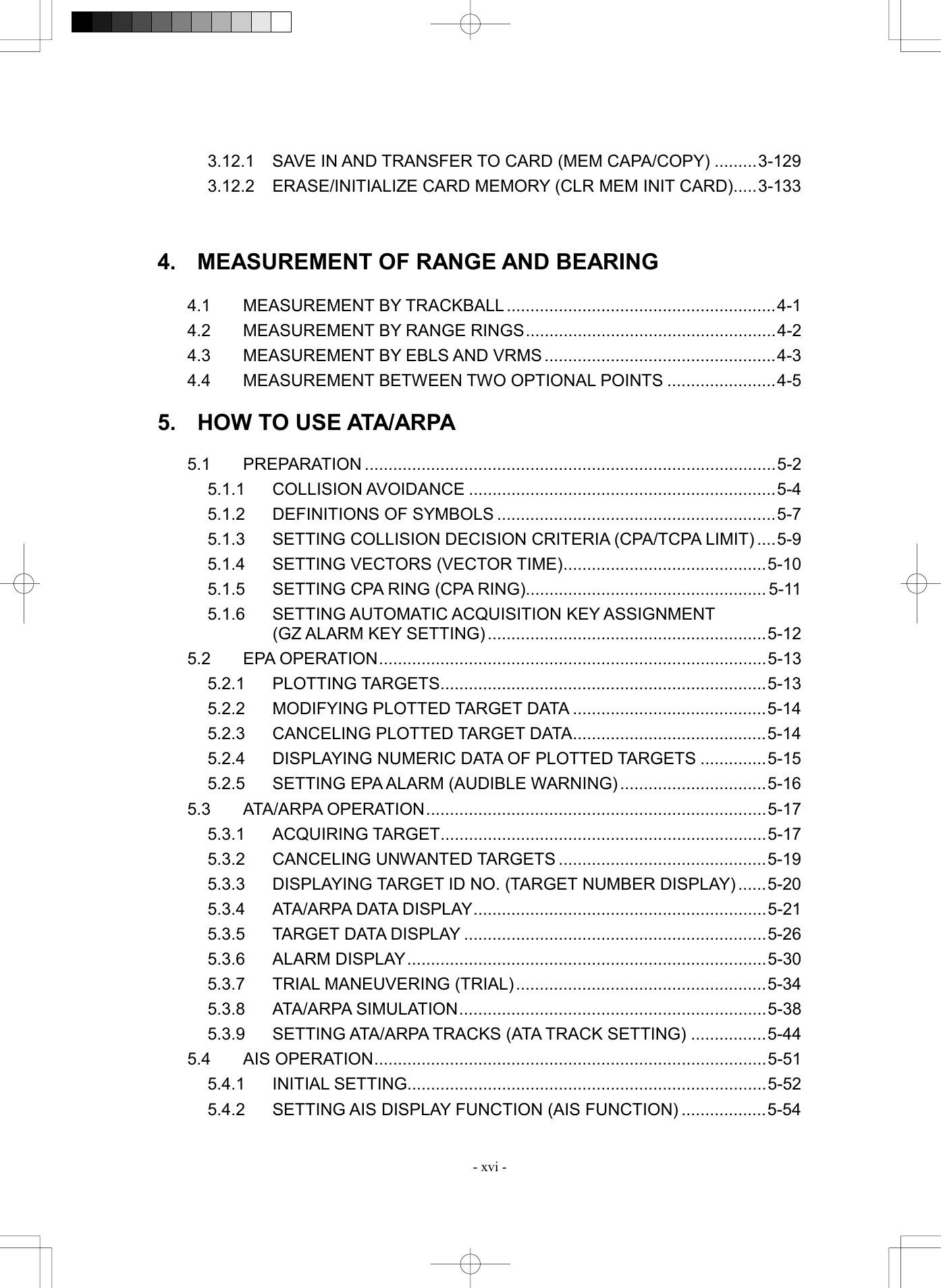
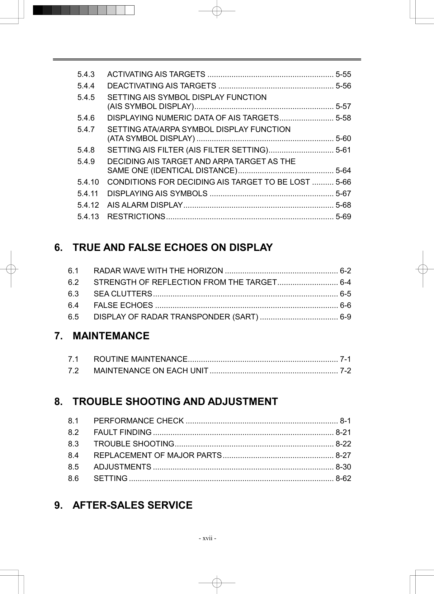
![SECTION 3 BASIC OPERATION 3.1 FLOW OPERATION ......................................................................................3-1 3.1.1 Power ON and Start the System ......................................................3-2 3.1.2 Observe and Adjust Video................................................................ 3-3 3.1.3 Acquire and Measure Data ............................................................... 3-3 3.1.4 End the Operation and Stop the System.........................................3-4 3.2 MENU COMPOSITION..................................................................................3-5 3.2.1 Overview of Menu Structure............................................................. 3-5 3.2.2 Basic Menu Operation ......................................................................3-6 3.3 PREPARATION .............................................................................................3-8 3.3.1 Adjust Display Brilliance .................................................................. 3-8 3.3.2 Adjust Contrast .................................................................................3-8 3.3.3 Adjust Operation Panel Brilliance [PANEL] ....................................3-9 3.3.4 Switch Day/Night Mode [DAY/NIGHT].............................................. 3-9 3.3.5 Adjust Brilliance of Information on Radar Display (Brilliance Setting) ..........................................................................3-10 3.3.6 Adjust Sound Volume (Buzzer Volume) ........................................ 3-11 3.3.7 Reset Alarm Buzzer [ALARM ACK]................................................ 3-11 3.3.8 Set Display Color ............................................................................3-12 3.4 BASIC OPERATIONS .................................................................................3-15 3.4.1 Start Transmission [TX/PRF].......................................................... 3-15 3.4.2 Stop Transmission [STBY] .............................................................3-15 3.4.3 Change Range (Observation Range Scale) [RANGE+/-]..............3-15 3.4.4 Tune..................................................................................................3-16 3.4.5 Control Sensitivity [GAIN/PL] ........................................................3-16 3.4.6 Suppress Sea Clutter [AUTO-SEA]................................................ 3-17 3.4.7 Suppress Rain/Snow Clutter [AUTO-RAIN]...................................3-19 3.4.8 Reject Radar Interference [IR]........................................................ 3-21 3.4.9 Hide/Display Range Rings (RINGS) ...............................................3-22 3.4.10 Hide Ship’s Heading Line (HL OFF)...............................................3-22 3.4.11 Hide Graphics Information on Radar Display (Graphic Display) ............................................................................3-23 3.5 GENERAL OPERATIONS ........................................................................... 3-24 3.5.1 Move Cross Cursor Mark by Trackball..........................................3-24 3.5.2 Use EBLs (Electronic Bearing Lines) [EBL1/2].............................3-25 3.5.3 Set EBL Operation (EBL1 /2 Setting)............................................. 3-27 3.5.4 Display Variable Range Markers [VRM1/VRM2]............................3-30 3.5.5 Display Parallel Index Lines (Parallel Index Line) ........................ 3-33 3.5.6 Switch Bearing Display Mode [AZI MODE] ...................................3-41 3.5.7 Switch True/Relative Motion Display Mode [TM/RM] ...................3-42 3.5.8 Move Own Ship’s Display Position [OFF CENT] ..........................3-43 3.5.9 Display Other Ships’ Trails [TRAILS].............................................3-44 3.5.10 Switch Pulse Length (GAIN/PL) .....................................................3-47 3.5.11 Expand Targets (Target Enhance)..................................................3-48 3.5.12 Use Video Process (Process).........................................................3-49 3.5.13 Zoom................................................................................................ 3-50 3.5.14 Use Marker [MOB]........................................................................... 3-51 3.5.15 Marking [MARK].............................................................................. 3-52 3.5.16 Operate EBL Maneuver Function (EBL Maneuver) ...................... 3-53 3.5.17 Operate Multi-Function Control [MULTI]....................................... 3-56 3.5.18 Operate User Key Switches [User Key 1/2] .................................. 3-58 3.5.19 Operation of Guard Zone [ATA Guard Zone] ................................ 3-60 3.5.20 Radar Alarm (Radar Alarm) ............................................................ 3-63 3.6 DISPLAY OWN SHIP’S TRACK ................................................................. 3-67 3.6.1 Display Own Ship’s Track (Display Own Track)........................... 3-67 3.6.2 Set Own Ship’s Track Data Storage Interval (Own Track Interval) ....................................................................... 3-68 3.6.3 Clear Own Ship’s Track Data (Clear Own Track).......................... 3-69 3.6.4 Cancel Storing of Own Ship’s Track Data (Own Track Memory) ...................................................................... 3-70 3.7 DISPLAY CHARTS...................................................................................... 3-71 3.7.1 Display Coastline ROM Card Produced by JRC........................... 3-71 3.7.2 Display ERC Card ........................................................................... 3-72 3.7.3 Fill Charts (Fill Land Area) ............................................................. 3-73 3.8 DISPLAY NAVIGATION INFORMATION..................................................... 3-74 3.8.1 Display Waypoint Marks (Waypoint Display)................................ 3-74 3.8.2 Display Navigation Information (NAV Display Setting) ............... 3-75 3.8.3 Create/Edit Navigation Information (Edit User Map).................... 3-76 3.8.4 Set Navigation Information (User Map Setting)............................ 3-82 3.8.5 Set and Display Geodetic System................................................. 3-89 3.9 OPERATE PERFORMANCE MONITOR (PM DISPLAY) ............................ 3-91 3.9.1 Operation Procedures .................................................................... 3-91 3.10 APPLIED OPERATIONS............................................................................. 3-97 3.10.1 Set Radar Signal Processing (Process Setting)........................... 3-97 3.10.2 Set Radar Trails (RADAR Trails Setting)..................................... 3-100 3.10.3 Set Cursor (Cursor Setting) ......................................................... 3-102 3.10.4 Set Screen ..................................................................................... 3-103 3.10.5 Set Scanner (TRX Setting) ........................................................... 3-107 3.10.6 Set Chart Display (Map Setting) .................................................. 3-109 3.10.7 Set LORAN C (LORAN C Correction) .......................................... 3-119 3.11 USE FUNCTION SWITCH [FUNC] ........................................................... 3-120 3.11.1 Operation Procedures .................................................................. 3-120 3.11.2 Function Setting Menu Items....................................................... 3-121 3.11.3 Overview of Function Operations ............................................... 3-122 3.11.4 Overview of Stored Function Setting Data ................................. 3-125 3.11.5 Personal Information (PIN Setting) ............................................. 3-126 3.12 USING CARD............................................................................................ 3-129 3.12.1 Save in and Transfer to Card (MEM CAPA/Copy)....................... 3-129 3.12.2 Erase/Initialize Card Memory (CLR MEM INIT Card).................. 3-133](https://usermanual.wiki/Japan-Radio/NKE2252.Instruction-manual-1-of-3/User-Guide-482878-Page-67.png)
![3─3 Procedures 1 Check that the ship’s mains are turned on. 2 Press [STBY] key. The system is turned on, and the preheating time is displayed. PREHEAT is indicated at the upper left of the radar display. 3 Wait until the preheating time is over. When the preheating time is over, the preheating time screen disappears, and PREHEAT at the upper left of the radar display changes to STANDBY . 4 Press [TX/PRF] key. The radar will start transmission and the antenna will start rotating. STANDBY at the upper left of the radar display changes to TRANSMIT . Note: The radar does not start transmission if you press [TX/PRF] key while PREHEAT is indicated. 3.1.2 Observe and Adjust Video Procedures 1 Press [RANGE+] key or [RANGE-] key to set the range to the scale required for target observation. 2 Turn the controls [GAIN], [SEA], and [RAIN] to obtain the clearest targets. Refer to [GAIN]→3-16 [SEA]→3-17 [RAIN]→3-19 for how to use each control. 3.1.3 Acquire and Measure Data For details on data acquisition and measurement, refer to Section 3.4 “BASIC OPERATIONS” and Section 4 “MEASUREMENT OF RANGE AND BEARING.”](https://usermanual.wiki/Japan-Radio/NKE2252.Instruction-manual-1-of-3/User-Guide-482878-Page-70.png)
![3─4 3 3.1 FLOW OPERATION 3.1.4 End the Operation and Stop the System Exit 1 Press [STBY] key. The radar will stop transmission and the antenna will stop rotating. TRANSMIT at the upper left of the radar display changes to STANDBY . Maintain the standby state if radar observation is restarted in a relatively short time. Only pressing the [TX/PRF] key starts observation. 2 Press the [STBY] key and the [TX/PRF] key together. The system will be turned off. When conducting maintenance work, make sure to turnoff the power and unplug the power connector J1 of theprocessor so that the power supply to the equipment iscompletely cut off. Some equipment components can carry electrical current even after the power switch is turned off, andconducting maintenance work without unplugging thepower connector may result in electrocution,equipment failure, or accidents. Warning](https://usermanual.wiki/Japan-Radio/NKE2252.Instruction-manual-1-of-3/User-Guide-482878-Page-71.png)
![3─5 3.2 MENU COMPOSITION The Menu system of this radar equipment consists of the main menu and the submenus up to the lower 2 levels. You can jump to each menu by pressing the menu button at the lower right of the radar display or the switch on the operation panel. 3.2.1 Overview of Menu Structure Press [RADAR MENU] key. Press [RADAR MENU] key or [9]. Press [8]. Use the Main Menu to change the settings of signal processing functions, use the radar menu to change the settings of other detailed information, and use the Radar Submenus to change the less frequently used settings or run the system’s self-diagnostic program. Main Menu 1. IR IR OFF2. Process PROC OFF3. Target Enhance OFF4. Zoom OFF5. SART OFF6. NAV Information > 7. 8. Graphic Display ON9. Radar Menu(→Plot) > 0. EXIT RADAR Menu 1. Process Setting > 2. RADAR Trails Setting > 3. Marker Setting > 4. Screen Setting >5. TRX Setting > 6. Inter Switch Setting > 7. NAV Equipment Setting> 8. RADAR Sub Menu >9. Plot Menu > 0. EXIT RADAR Sub Menu 1. PIN Setting >2. Multi Dial Setting >3. User Key Setting > 4. Date/Time Setting >5. Buzzer Volume LEVEL3 9. Test Menu > 0. EXIT](https://usermanual.wiki/Japan-Radio/NKE2252.Instruction-manual-1-of-3/User-Guide-482878-Page-72.png)
![3─6 3 3.2 MENU COMPOSITION 3.2.2 Basic Menu Operation To open the menu: Press [RADAR MENU] key. To close the menu: Press [RADAR MENU] key. Alternatively, hold down [0] key until the menu closes. * Button 54 on the radar display on page 2-7 is also available to switch between ON and OFF. To move to a lower level of the menu: The menu is in hierarchical structure. Press the numeric keys [1]-[9] corresponding to the desired menu item number. Control will move to the lower level. Alternatively, place the cursor over the item and then press [ENT] key. > is shown at the right end of a menu item having a lower level. To move to a higher level of the menu: Press [0] key while the menu is open. Control will return to the higher level from the lower level. Alternatively, place the cursor over the 0.EXIT item and then press [ENT] key. To determine an item: Press the numeric keys [1]-[9] corresponding to the desired item number. The selected item will be displayed. Alternatively, place the cursor over the item you want to change, and then press [ENT] key. To determine the selected item: Press the numeric keys [1]-[9] corresponding to the selected item number. Alternatively, place the cursor over the selected item and then press [ENT] key. If you do not change the setting of the selected item, press [CLR/INFO] key.](https://usermanual.wiki/Japan-Radio/NKE2252.Instruction-manual-1-of-3/User-Guide-482878-Page-73.png)
![3─7 Menu Operation with the Trackball The menu items are software buttons that can be operated with the trackball. An item can be selected by pointing the trackball cursor to the item and pressing [ENT] key, instead of using the numeric key. Example of menu display Process Setting1. Video LatitudeNORMAL2. VD Noise RejectionLOW3. Auto DR ControlON4. Process SwitchOFF5. 2nd Process ModeREMAIN6.Process Switch Range6.2nm7. Fast Target DetectionOFF8. User Function Setting >0. EXITNORMAL1.WIDE2.NARROW3.Item numberSoftware buttonThe selected item is displayed by pressing the corresponding numeric key. An item can be selected by pressing the corresponding numeric key. An item can also be selected by the trackball and by pressing [ENT] key.An item can also be selected by pointing the trackball cursor to the item and pressing [ENT] key. Press [8] key to move to the lower level. Movement to the lower level can also be done by pointing the trackball cursor to the item and pressing [ENT] key.Press [0] key move to the higher level. Movement to the higher level can also be done by pointing the trackball cursor to 0.EXITand pressing [ENT] key.](https://usermanual.wiki/Japan-Radio/NKE2252.Instruction-manual-1-of-3/User-Guide-482878-Page-74.png)
![3─8 3 3.3 PREPARATION 3.3.1 Adjust Display Brilliance Procedures 1 Obtain the best-to-see display with optimum brilliance by turning the [BRILL] control at the lower right of the display unit. Turning the [BRILL] control clockwise increases the brilliance of the entire display. Conversely, turning the [BRILL] control counterclockwise decreases the brilliance of the entire display. In consideration of the ambient brightness, adjust display brilliance that is high enough to easily observe the radar display but does not glare. 3.3.2 Adjust Contrast Adjust the contrast of the radar video display. Procedures 1 Point the trackball to the VID button (* Button 61 on the radar display on page 2-7) at the lower right of the radar display, press [ENT] key, and then make adjustment to obtain the best-to-see video. Point the trackball to the VID button at the lower right of the radar display and then press [ENT] key to adjust the contrast of the radar video display at four levels. Each time the VID button is clicked, the contrast level changes in the following sequence: Adjust the VID button to obtain the best-to-see video with optimum contrast.](https://usermanual.wiki/Japan-Radio/NKE2252.Instruction-manual-1-of-3/User-Guide-482878-Page-75.png)
![3─9 3.3.3 Adjust Operation Panel Brilliance [PANEL] Procedures 1 Press [PANEL] key to adjust the brilliance of the operation panel light. There are five brilliance levels, and brilliance increases by one level each time the [PANEL] key is pressed. When it reaches the highest level, it is resumed to the lowest level. In consideration of the ambient brightness, adjust panel brilliance that is high enough to read the characters on the operation panel but does not glare. The [PANEL] key lamp lights up irrespective of panel brilliance adjustment. * Button 60 on the radar display on page 2-7 is also available for switching. 3.3.4 Switch Day/Night Mode [DAY/NIGHT] The day/night mode changes in the following sequence each time the [DAY/NIGHT] key is pressed: DAY1 ® DAY2 ® NIGHT1 ® NIGHT2 The current mode is indicated at the lower right of the radar display. The brilliance level in accordance with the selected mode is saved. For brilliance adjustment, refer to page next page. For day/night mode switching, refer to 3-12page Section 3.3.8 “Set Display Color.” * Button 63 on the radar display on page 2-7 is also available for switching.](https://usermanual.wiki/Japan-Radio/NKE2252.Instruction-manual-1-of-3/User-Guide-482878-Page-76.png)
![3─10 3 3.3 PREPARATION Brilliance Setting1. RADAR VideoLEVEL42. RADAR TrailsLEVEL43. ATA/AISLEVEL34. Fix MarkerLEVEL25. EBL/VRMLEVEL26. CharacterLEVEL47. PanelLEVEL4 0. EXITLEVEL11.LEVEL22.LEVEL33.LEVEL44. 3.3.5 Adjust Brilliance of Information on Radar Display (Brilliance Setting) Brilliance can be adjusted for each item of information on the radar display by operating the menu. RADAR Video Adjusts the brilliance of radar echoes. RADAR Trails Adjusts the brilliance of radar trails. ATA/AIS Adjusts the brilliance of ATA symbols and AIS symbols. FIX Marker Adjusts the brilliance of fixed range markers. EBL/VRM Adjusts the brilliance of variable range markers (VRM1 and VRM2) and electronic bearing lines (EBL1 and EBL2). Character Adjusts the brilliance of characters. Panel Adjusts the brilliance of operation panel. Procedures 1 Press [RADAR MENU] key twice. Press [4] key. Press [2] key. The Brilliance Setting Menu will appear. 2 Select the item for which brilliance is to be adjusted, pressing the numeric keys [1] to [7]. The pull-down menu will appear showing the brilliance levels. 3 Select the brilliance level number to be set, pressing the numeric key. The selected brilliance level will be set. To change the setting of another item, repeat steps 2 and 3. Exit 1 Press [RADAR MENU] key. The menu will be closed. Note: The brilliance levels set here are saved in accordance with the day/night mode.](https://usermanual.wiki/Japan-Radio/NKE2252.Instruction-manual-1-of-3/User-Guide-482878-Page-77.png)
![3─11 3.3.6 Adjust Sound Volume (Buzzer Volume) Procedures 1 Press [RADAR MENU] key twice. Press [8] key. The RADAR Sub Menu will appear. 2 Press [5] key to select Buzzer Volume. The pull-down menu will appear showing the volume levels. 3 Select the volume level number to be set, pressing the numeric keys [1] to [5]. The selected volume level will be set. Exit 1 Press [RADAR MENU] key. The menu will be closed. 3.3.7 Reset Alarm Buzzer [ALARM ACK] When an audible alarm is issued, use ALARM ACK to acknowledge the alarm information, stop the alarm buzzing, and stop the alarm lamp flashing. (If more than one alarm has occurred, press the switch for each alarm indication.) The alarm stops buzzing, but the alarm indication does not disappear. Procedures 1 Press [ALARM ACK] key. The alarm will stop buzzing. * Button 64 on the radar display on page 2-7 is also available to stop buzzing the alarm. RADAR Sub Menu1. PIN Setting2. Multi Dial Setting3. User Key Setting4. Date/Time Setting5. Buzzer VolumeLEVEL4 9. Test Menu0. EXIT LEVEL41. OFF5.2. LEVEL13. LEVEL24. LEVEL3](https://usermanual.wiki/Japan-Radio/NKE2252.Instruction-manual-1-of-3/User-Guide-482878-Page-78.png)
![3─12 3 3.3 PREPARATION 3.3.8 Set Display Color For each day/night mode, set the colors of the background outside the bearing scale, the background inside the bearing scale, characters, radar echoes, and radar trails. Color Adjustment by Menu Operation Day/Night Registers the switching of a day/night mode. Color Scheme Calls a preset color scheme pattern. Outer PPI Adjusts the background color outside the bearing scale. Inner PPI Adjusts the background color inside the bearing scale. Character Adjusts the colors of characters and bearing scales. RADAR Echo Adjusts the colors of radar echoes. RADAR Trails Adjusts the colors of radar trails. Time: Display interval time is selected. Cont: Continuous display Selecting a Day/Night Mode (Day/Night) Select the mode for which color setting is to be changed. Procedures 1 Press [RADAR MENU] key twice. Press [4] key. Press [1] key. The Display Color Setting Menu will appear. 2 Press [1] key. The Day/Night mode selection screen will appear. 3 Select the mode number for color adjustment, pressing the numeric keys [1] to [4]. The mode will be selected. Display Color Setting1. Day/NightDAY12. Color SchemeORIGINAL3. Outer PPIGRAY4. Inner PPIBLACK5. CharacterWHITE6. RADAR EchoYELLOW7. RADAR Trails ( Time )CYAN8. RADAR Trails ( Cont )WHITE 0. EXITDAY11.DAY22.NIGHT13.NIGHT24.](https://usermanual.wiki/Japan-Radio/NKE2252.Instruction-manual-1-of-3/User-Guide-482878-Page-79.png)
![3─13 Calling of a Color Scheme (Color Scheme) Call a preset color scheme pattern. Procedures 1 Press [2] key while the Display Color Setting Menu is open. The Color Scheme Menu will appear. 2 Select the pattern number to be set, pressing the numeric keys [1] to [6]. The selected color scheme pattern will be set. Display Color Setting1. Day/NightDAY12. Color SchemeORIGINAL3. Outer PPIGRAY4. Inner PPIBLACK5. CharacterWHITE6. RADAR EchoYELLOW7. RADAR Trails ( Time )CYAN8. RADAR Trails ( Cont )WHITE 0. EXIT STANDARD1.FLASHY2.PLANE3.70’s4.SAFARI5.ORIGINAL6.](https://usermanual.wiki/Japan-Radio/NKE2252.Instruction-manual-1-of-3/User-Guide-482878-Page-80.png)
![3─14 3 3.3 PREPARATION Setting Colors of Items Set the display color of each item. Procedures 1 While the Display Color Setting Menu is open, select the item number for color setting, pressing the numeric keys [3] to [8]. The color selection screen will appear. 3. Outer PPI: Adjusts the background color outside the bearing scale. 4. Inner PPI: Adjusts the background color inside the bearing scale. 5. Character: Adjusts the colors of characters and bearing scales. 6. RADAR Echo: Adjusts the colors of radar echoes. 7. 8. RADAR Trails: Adjusts the colors of radar trails. Time: Display interval time is selected. Cont: Continuous display 2 Select the color number to be set, pressing the numeric key. The selected color will be set. To set more than one color, repeat steps 1 and 2. Exit 1 Press [RADAR MENU] key. The menu will be closed. Display Color Setting1. Day /NightDAY12. Color SchemeORIGINAL3. Outer PPIGRAY4. Inner PPIBLACK5. CharacterWHITE6. RADAR EchoYELLOW7. RADAR Trails ( Time )CYAN8. RADAR Trails ( Cont )WHITE 0. EXIT 1.BLUE2.DARK BLUE3.BLACK4.GRAY](https://usermanual.wiki/Japan-Radio/NKE2252.Instruction-manual-1-of-3/User-Guide-482878-Page-81.png)
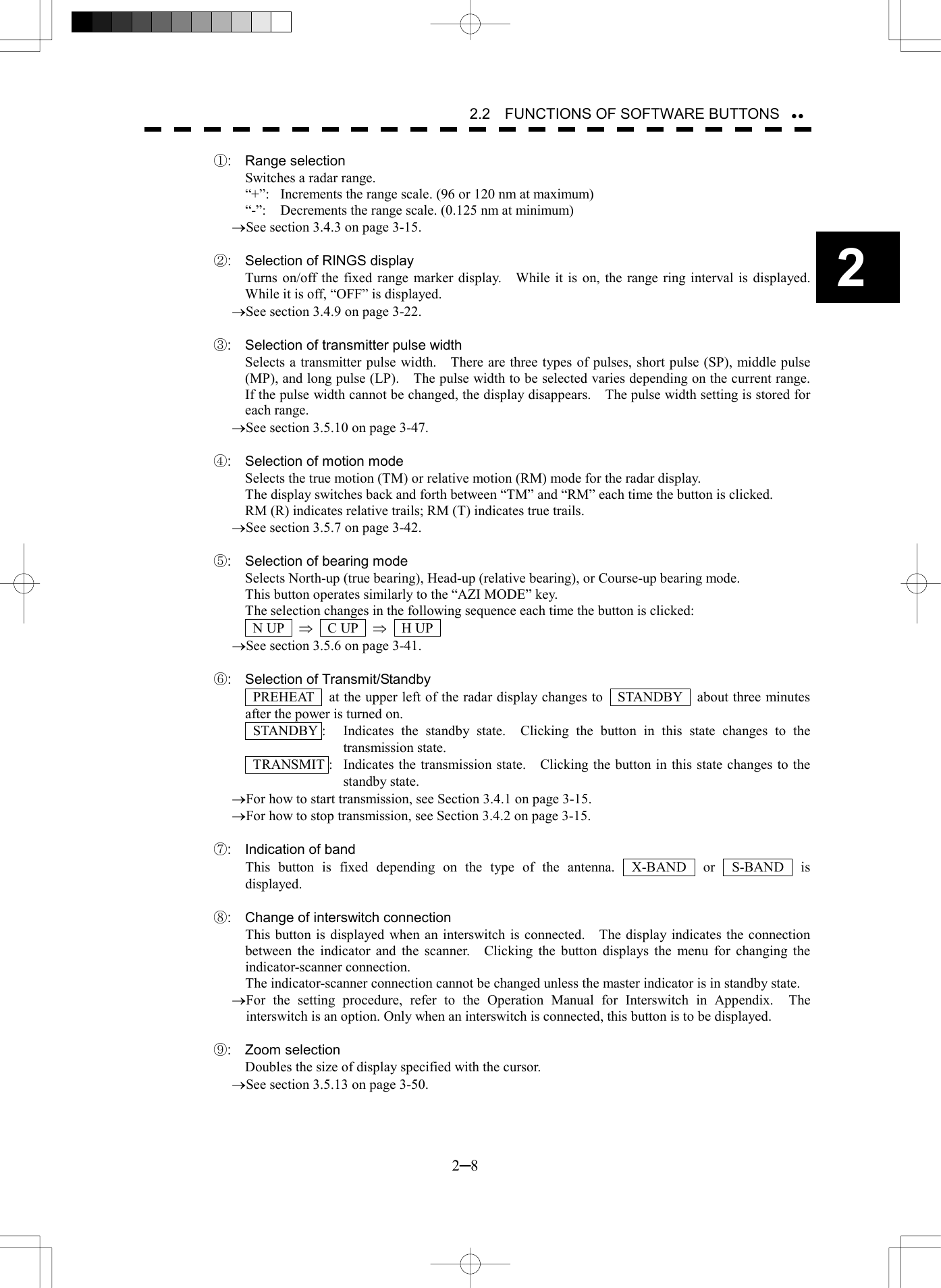
![3─15 3.4 BASIC OPERATIONS 3.4.1 Start Transmission [TX/PRF] Procedures 1 Press [TX/PRF] key. The radar will start transmission and the antenna will start rotating. The indication STANDBY at the upper left of the radar display changes to TRANSMIT . Note: The radar does not start transmission if you press [TX/PRF] key while PREHEAT is indicated. 3.4.2 Stop Transmission [STBY] Procedures 1 Press [STBY] key. The radar will stop transmission and the antenna will stop rotating. The indication TRANSMIT at the upper left of the radar display changes to STANDBY . * Button 6 on the radar display on page 2-7 is also available to start/stop transmission. 3.4.3 Change Range (Observation Range Scale) [RANGE+/-] Procedures 1 Press [RANGE+] key or [RANGE-] key to set the range to the scale required for target observation. To observe long-range targets, press [RANGE+] key. To zoom and observe a short-range target near the own ship, press [RANGE-] key. * Button 1 on the radar display on page 2-7 is also available to switch the range.](https://usermanual.wiki/Japan-Radio/NKE2252.Instruction-manual-1-of-3/User-Guide-482878-Page-82.png)
![3─16 3 3.4 BASIC OPERATIONS 3.4.4 Tune This system tunes the transmitting frequency and receiving frequency under automatic control, so it does not need any tuning by hand 3.4.5 Control Sensitivity [GAIN/PL] Procedures 1 Control noise on the radar display by turning the [GAIN/PL] control until targets can be easily observed. Turning [GAIN/PL] control clockwise increases sensitivity. Turning [GAIN/PL] control counterclockwise decreases sensitivity. Turning the [GAIN/PL] control clockwise increases receiving sensitivity and extends the radar observation range. If the sensitivity is too high, the receiver noise increases reducing the contrast between the targets and the background video. As a result, the targets become obscure on the radar display. To observe densely crowded targets or short-range targets, turn the [GAIN/PL] control counterclockwise to reduce the sensitivity so that the targets are easy to observe. However, be careful not to overlook important small targets.](https://usermanual.wiki/Japan-Radio/NKE2252.Instruction-manual-1-of-3/User-Guide-482878-Page-83.png)
![3─17 3.4.6 Suppress Sea Clutter [AUTO-SEA] Procedures 1 Control the sea clutter returns on the radar display by turning the [AUTO-SEA] control until targets can be easily observed. Turning [AUTO-SEA] control clockwise suppresses sea clutter returns. Turning [AUTO-SEA] control counterclockwise intensifies sea clutter returns. The sea clutter suppression function suppresses sea clutter returns by decreasing the receiving sensitivity on a short range. Turning the [AUTO-SEA] control clockwise heightens the effect of sea clutter suppression. However, be careful that excessive suppression causes low signal-strength targets such as buoys and boats to disappear from the radar display. Before sea clutter returns can be suppressed in accordance with their intensity, the automatic sea clutter suppression mode must be selected by pressing the [AUTO-SEA] control. Use this automatic mode when sea clutter returns vary in direction. To change back to the manual mode, press the [AUTO-SEA] control again. Note: The AUTO SEA (automatic sea clutter suppression) mode and the AUTO RAIN (automatic rain/snow clutter suppression) mode cannot be used at the same time. Using AUTO SEA (automatic sea clutter suppression function) Procedures 1 Press the [AUTO-SEA] control. AUTO SEA is selected, and SEA AUTO is indicated at the lower left of the radar display. If AUTO SEA is selected, rotating the AUTO RAIN control and AUTO SEA control can make fine adjustments manually. When using the [AUTO SEA] function, never set the suppression level too high canceling out all imagenoises from the sea surface at close range. Detection of not only echoes from waves but alsotargets such as other ships or dangerous objects willbecome inhibited. When using the [AUTO SEA] function, make sure tochoose the most appropriate image noise suppressionlevel. Caution](https://usermanual.wiki/Japan-Radio/NKE2252.Instruction-manual-1-of-3/User-Guide-482878-Page-84.png)
![3─18 3 3.4 BASIC OPERATIONS Note: When AUTO SEA is selected, AUTO RAIN is switched to the manual mode. AUTO SEA and AUTO RAIN cannot be selected at the same time. Cancellation 1 Press the [AUTO-SEA] control. AUTO SEA is deselected, SEA AUTO at the lower left of the radar display changes to SEA MAN , and AUTO SEA is cancelled. * Button 14 on the radar display on page 2-7 is also available to switch AUTO/MANUAL.](https://usermanual.wiki/Japan-Radio/NKE2252.Instruction-manual-1-of-3/User-Guide-482878-Page-85.png)
![3─19 3.4.7 Suppress Rain/Snow Clutter [AUTO-RAIN] Procedures 1 Control the rain/snow clutter returns on the radar display by turning the [AUTO-RAIN] control until targets can be easily observed. Turning [AUTO-RAIN] control clockwise suppresses rain/snow clutter returns. Turning [AUTO-RAIN] control counterclockwise intensifies rain/snow clutter returns. When the [AUTO-RAIN] control is turned clockwise, the rain/snow clutter suppression function suppresses rain/snow clutter returns and gets targets hidden by rain/snow clutter returns to appear on the radar display. However, be careful that excessive suppression may cause small targets to be overlooked. Since the rain/snow clutter suppression function also has the effect of suppressing sea clutter, the suppression efficiency improves when the [AUTO-RAIN] control is used with the [AUTO-SEA] control. In general, turn the [AUTO-RAIN] control fully to the left. Before rain/snow clutter returns can be suppressed in accordance with their intensity, the automatic rain/snow clutter suppression mode must be selected by pressing the [AUTO-RAIN] control. To change back to the manual mode, press the [AUTO-RAIN] control again. Note: The AUTO SEA (automatic sea clutter suppression) mode and the AUTO RAIN (automatic rain/snow clutter suppression) mode cannot be used at the same time. Using AUTO RAIN (automatic rain/snow clutter suppression function): Procedures 1 Press the [AUTO-RAIN] control. AUTO RAIN is selected, and RAIN AUTO is indicated at the lower left of the radar display. Rotating the AUTO RAIN control and AUTO SEA control can make fine adjustments manually. When using the [AUTO RAIN] function, never set thesuppression level too high canceling out all imagenoises from the rain or snow at the close range. Detection of not only echoes from the rain or snow butalso targets such as other ships or dangerous objectswill become inhibited. When using the [AUTO RAIN] function, make sure tochoose the most appropriate image noise suppressionlevel. Caution](https://usermanual.wiki/Japan-Radio/NKE2252.Instruction-manual-1-of-3/User-Guide-482878-Page-86.png)
![3─20 3 3.4 BASIC OPERATIONS Note: When AUTO RAIN is selected, AUTO SEA is switched to the manual mode. AUTO SEA and AUTO RAIN cannot be selected at the same time. Cancellation 1 Press the [AUTO-RAIN] control. AUTO RAIN is deselected, RAIN AUTO at the lower left of the radar display changes to RAIN MAN , and AUTO RAIN is cancelled. * Button 15 on the radar display on page 2-7 is also available to switch AUTO/MANUAL.](https://usermanual.wiki/Japan-Radio/NKE2252.Instruction-manual-1-of-3/User-Guide-482878-Page-87.png)
![3─21 3.4.8 Reject Radar Interference [IR] Procedures 1 Press [RADAR MENU] key. The Main Menu will appear. 2 Press [1] key. The IR Menu will appear. 3 Select the level number to be set, pressing the numeric keys [1] to [4]. The selected level will be set. Rejection levels of the interference rejector IR OFF: Interference rejector off IR LOW: Interference rejection level - low IR MEDIUM: Interference rejection level - moderate IR HIGH: Interference rejection level - high When a high interference rejection level is selected, the radar’s ability of detecting small targets such as buoys and small boats lowers. In general, [IR LOW] should be selected. * Button 10 on the radar display on page 2-7 is also available to switch IR settings. l When viewing a radar beacon or SART signal, select IR OFF (Interference Rejector OFF) because IR processing suppresses the video. AttentionMain Menu1. IR IR OFF2. PROCESPROC OFF3. TARGET ENHANCEOFF4. Zoom OFF5. SART OFF 6. NAV Information7. 8. Graphic DisplayON9. RADAR Menu (Plot)0. EXIT IR OFF1.IR LOW2.IR MEDIUM3.IR HIGH4.](https://usermanual.wiki/Japan-Radio/NKE2252.Instruction-manual-1-of-3/User-Guide-482878-Page-88.png)
![3─22 3 3.4 BASIC OPERATIONS 3.4.9 Hide/Display Range Rings (RINGS) Procedures 1 Press [RR/HL] key. The range rings display switches back and forth between display and non-display each time [RR/HL] key is pressed. Refer to page 3-10 for how to change the brilliance of range rings. * Button 2 on the radar display on page 2-7 is also available to switch between ON and OFF. 3.4.10 Hide Ship’s Heading Line (HL OFF) Procedures 1 Hold down [RR/HL] key. The ship’s heading line is hidden while [RR/HL] key is held down. The ship’s heading line (HL) that presents the course of own ship is always shown on the radar display. The heading line is hidden while [RR/HL] key is held down, so the targets on the heading line can be easily observed. * Button 22 on the radar display on page 2-7 is also available to switch between ON and OFF.](https://usermanual.wiki/Japan-Radio/NKE2252.Instruction-manual-1-of-3/User-Guide-482878-Page-89.png)
![3─23 Main Menu1. IR IR OFF2. ProcessPROC OFF3. Target EnhanceOFF4. Target EnhanceOFF5. SART OFF6. NAV Information7. 8. Graphic DisplayON9. RADAR Menu ( Plot )0. EXIT 3.4.11 Hide Graphics Information on Radar Display (Graphic Display) Procedures 1 Press [RADAR MENU] key. The Main Menu will appear. 2 Press [8] key. The setting of Graphic Display will be changed to ON . Graphics information other than VRMs, EBLs, HL, cross cursor mark, and range rings on the radar display is temporarily hidden. Cancellation 1 Press [RADAR MENU] key. The Main Menu will appear. 2 Press [8] key. The setting of Graphic Display will be changed back to OFF . Temporarily hidden graphics information is displayed again. Various graphics information such as ATA/AIS symbols, NAV lines, and MAP information is shown on the radar display of this system, and may make it difficult to view the radar video. In this case, use this function to temporarily hide unnecessary graphics information.](https://usermanual.wiki/Japan-Radio/NKE2252.Instruction-manual-1-of-3/User-Guide-482878-Page-90.png)
![3─25 3.5.2 Use EBLs (Electronic Bearing Lines) [EBL1/2] EBLs (Electronic Bearing Lines) are indispensable to the measurement of bearings. Operators must be familiar with the operation of EBLs beforehand. EBL1 Operation If EBL2 is selected or EBL1 is not displayed, press [EBL1] key to select EBL1 before starting operation. (The currently selected EBL is shown in reverse video at the lower right of the radar display.) Procedures 1 Press [EBL1] key. EBL1 at the lower right of the radar display will be shown in reverse video, and EBL1 becomes operable. 2 Press [EBL1] key again. The EBL1 display will disappear. * Button 31 on the radar display on page 2-7 is also available to switch EBL1 between ON and OFF. EBL2 Operation If EBL1 is selected or EBL2 is not displayed, press [EBL2] key to select EBL2 before starting operation. (The currently selected EBL is shown in reverse video at the lower right of the radar display.) Procedures 1 Press [EBL2] key. EBL2 at the lower right of the radar display will be shown in reverse video, and EBL2 becomes operable. 2 Press [EBL2] key again. The EBL2 display will disappear. * Button 32 on the radar display on page 2-7 is also available to switch EBL1 between ON and OFF. Operation procedures are described on the following pages. For how to measure distance and bearing, see Section 4.](https://usermanual.wiki/Japan-Radio/NKE2252.Instruction-manual-1-of-3/User-Guide-482878-Page-92.png)
![3─26 3 3.5 BASIC OPERATIONS EBL Bearing Display The bearing values of EBL1 and EBL2 currently displayed on the PPI are indicated at the lower right of the radar display. The currently operable EBL1 or EBL2 is shown in reverse video beside the bearing value. Starting Point of EBL The starting point of the currently operating EBL can be switched from the center of the radar display (CENTER) to any offset position (OFFSET). Note: The offset position of the EBL’s starting point can be fixed on the radar display or at specific latitude and longitude. (For details, refer to page 3-28.) [I] Offsetting the starting point of EBL1 while EBL1 is operating: Procedures 1 Press the [EBL] control. The indication C to the right of the EBL value at the lower right of the radar display will change to O , and “OFFSET” will be set. * Button 35 on the radar display on page 2-7 is also available to switch the offset of EBL1. * Button 36 on the radar display on page 2-7 is also available to switch the offset of EBL2. 2 Move the starting point of EBL1 with the trackball. 3 Press [ENT] key at the starting point of EBL1 you want to move. The starting point of EBL1 will be determined. If EBL2 is operating, the starting point of EBL2 is offset. [II] Moving the starting point of EBL1 to the own ship’s position while EBL1 is operating: Procedures 1 Press the [EBL] control twice. The indication O to the right of the EBL value at the lower right of the radar display will change to C , and “CENTER” will be set. * Button 35 on the radar display on page 2-7 is also available to switch EBL1 CENTER. * Button 36 on the radar display on page 2-7 is also available to switch EBL2 CENTER. If EBL2 is operating, the starting point of EBL2 moves to the own ship’s position.](https://usermanual.wiki/Japan-Radio/NKE2252.Instruction-manual-1-of-3/User-Guide-482878-Page-93.png)
![3─27 3.5.3 Set EBL Operation (EBL1 /2 Setting) [I] Setting the bearing display mode of EBL1 (EBL1 Bearing REF) Determine whether to display EBLs (Electronic Bearing Lines) in true bearing mode or relative bearing mode. Procedures 1 Press [RADAR MENU] key twice. Press [3] key Press [1] key. The EBL1 Setting Menu will appear. 2 Press [1] key. The setting of EBL1 Bearing REF will be switched between TRUE and RELATIVE . TRUE : EBL1 is displayed in true bearing mode. RELATIVE : EBL2 is displayed in relative bearing mode. * Button 39 on the radar display on page 2-7 is also available to switch the display mode of EBL1. [II] Setting the bearing display mode of EBL2 (EBL2 Bearing REF) Procedures 1 Press [RADAR MENU] key twice. Press [3] key. Press [2] key. The EBL2 Setting Menu will appear. Subsequently, set the bearing display mode of EBL2 performing the same operation as explained in [I]. * Button 40 on the radar display on page 2-7 is also available to switch the display mode of EBL2. EBL1 Setting1. EBL1 Bearing REFTRUE2. EBL1 FloatingOFF3. EBL1 Bearing FixSCREEN 0. EXIT](https://usermanual.wiki/Japan-Radio/NKE2252.Instruction-manual-1-of-3/User-Guide-482878-Page-94.png)
![3─28 3 3.5 BASIC OPERATIONS [III] Setting the mode to move the starting point of EBL1 (EBL1 Floating) When this function is set to L/L FIX and the starting point of an EBL is moved to a position, the starting point can be fixed at the latitude and longitude of that position. The function is effective when the bearing from a certain point is repeatedly measured. When the function is set to SCREEN FIX , the starting point of an EBL is fixed on the radar display. The starting point is always indicated at the same position on the radar display even when the own ship has moved. Procedures 1 Press [RADAR MENU] key twice. Press [3] key Press [1] key. The EBL1 Setting Menu will appear. 2 Press [2] key. The EBL1 Floating Setting Menu will appear. 3 Select the mode number to be set, pressing the numeric keys [1] to [3]. The selected mode will be set. OFF: Floating mode off SCREEN FIX: The starting point of EBL1 is fixed on the radar display. L/L FIX: The starting point of EBL1 is fixed at specific latitude and longitude. * Button 35 on the radar display on page 2-7 is also available to switch the Screen Fix and L/L Fix of EBL1. [IV] Setting the mode to move the starting point of EBL2 (EBL2 Floating) Procedures 1 Press [RADAR MENU] key twice. Press [3] key. Press [2] key. The EBL2 Setting Menu will appear. Subsequently, set the EBL2’s starting point move mode performing the same operation as explained in [III]. * Button 36 on the radar display on page 2-7 is also available to switch the Screen Fix and L/L Fix of EBL2. Notes: · The course data and the own ship’s latitude and longitude data are required for activating the L/L Fix mode. · While the L/L Fix mode is active, the starting point of an EBL will be returned to the center if it disappears from the radar display when moved. EBL1 Setting1. EBL1 Bearing REFTRUE2. EBL1 FloatingOFF3. EBL1 Bearing FixSCREEN 0. EXIT OFF1.SCREEN FIX2.3. L/L FIX](https://usermanual.wiki/Japan-Radio/NKE2252.Instruction-manual-1-of-3/User-Guide-482878-Page-95.png)
![3─29 [V] Setting the EBL1 bearing fix mode (EBL1 Bearing FIX) While this function is set to ANGLE , an EBL is fixed to the preset bearing. For example, if the true bearing 020° is preset, the EBL is fixed to the true bearing 020° even when the own ship turns. While the function is set to SCREEN , the EBL is fixed on the radar display. The starting point is always indicated at the same position on the radar display even when the own ship has moved. Procedures 1 Press [RADAR MENU] key twice. Press [3] key Press [1] key. The EBL1 Setting Menu will appear. 2 Press [3] key. The setting of EBL1 Bearing Fix will be switched between ANGLE and SCREEN . ANGLE : EBL1 bearing is fixed to the preset value. SCREEN : EBL1 bearing is fixed on the radar display. [VI] Setting the EBL2 bearing fix mode (EBL2 Bearing Fix) Procedures 1 Press [RADAR MENU] key twice. Press [3] key. Press [2] key. The EBL2 Setting Menu will appear. Subsequently, set the EBL2 bearing fix mode performing the same operation as explained in [V]. Note: The course data is required for activating this function. EBL1 Setting1. EBL1 Bearing REFTRUE2. EBL1 FloatingOFF3. EBL1 Bearing FixSCREEN 0. EXIT](https://usermanual.wiki/Japan-Radio/NKE2252.Instruction-manual-1-of-3/User-Guide-482878-Page-96.png)
![3─30 3 3.5 BASIC OPERATIONS 3.5.4 Display Variable Range Markers [VRM1/VRM2] This function is to display and select variable range markers (VRMs). Two VRMs are available: VRM1 is represented as a broken line, and VRM2 as a dotted line. When EBL1 is displayed, VRM1 marker appears on the EBL1. When EBL2 is displayed, VRM2 marker appears on the EBL2. If the starting point of an EBL is offset, the center of a VRM marker is positioned at the starting point of the EBL. VRM markers displayed on EBL1/EBL2 ○ mark: VRM1 ● mark: VRM2 VRM1 Operation If VRM2 is selected or VRM1 is not displayed, press [VRM1] to select VRM1 before starting operation. (The currently selected VRM is shown in reverse video at the lower right of the radar display.) Procedures 1 Press [VRM1] key. VRM1 at the lower right of the radar display will be shown in reverse video, and VRM1 becomes operable. 2 Press [VRM1] key again. The VRM1 display will disappear. * Button 33 on the radar display on page 2-7 is also available to switch VRM1 between ON and OFF. VRM Operations The variable range markers are displayed centering around own ship. Turning the [VRM] control clockwise makes the VRM larger. Turning the [VRM] control counterclockwise makes the VRM smaller.](https://usermanual.wiki/Japan-Radio/NKE2252.Instruction-manual-1-of-3/User-Guide-482878-Page-97.png)
![3─31 VRM2 Operation If VRM1 is selected or VRM2 is not displayed, press [VRM2] key to select VRM2 before starting operation. (The currently selected VRM is shown in reverse video at the lower right of the radar display.) Procedures 1 Press [VRM2] key. VRM2 at the lower right of the radar display will be shown in reverse video, and VRM2 becomes operable. 2 Press [VRM2] key again. The VRM2 display will disappear. * Button 34 on the radar display on page 2-7 is also available to switch VRM2 between ON and OFF. VRM Range Display (VRM 1/2 Range Unit) The values of VRM1 and VRM2 currently displayed on the PPI are indicated at the lower right of the radar display. The currently operable VRM1 or VRM2 is shown in reverse video beside the range value. VRM1 Range Unit Procedures 1 Press [RADAR MENU] key twice. Press [3] key. The Marker Setting Menu will appear. 2 Press [3] key. The VRM1 Range Unit Setting Menu will appear. 3 Select the unit number to be set, pressing the numeric keys [1] to [3]. The selected unit will be set. * Button 37 on the radar display on page 2-7 is also available to switch VRM1 range unit. 2.Marker Setting1. EBL1 Setting2. EBL2 Setting3. VRM1 Range Unitnm4. VRM2 Range Unitnm5. Parallel Index Line6. Cursor Setting7. EBL Maneuver Setting 0. EXIT nm1.kmsm3.](https://usermanual.wiki/Japan-Radio/NKE2252.Instruction-manual-1-of-3/User-Guide-482878-Page-98.png)
![3─32 3 3.5 BASIC OPERATIONS VRM2 range unit Procedures 1 Press [RADAR MENU] key twice. Press [3] key. The Marker Setting Menu will appear. 2 Press [4] key. The VRM2 Range Unit Setting Menu will appear. 3 Select the item you want to set, pressing the numeric keys [1] to [3]. The selected item will be set. * Button 38 on the radar display on page 2-7 is also available to switch the VRM2 range unit. 2.Marker Setting1. EBL1 Setting2. EBL2 Setting3. VRM1 Range Unitnm4. VRM2 Range Unitnm5. Parallel Index Line6. Cursor Setting7. EBL Maneuver Setting 0. EXIT nm1.kmsm3.](https://usermanual.wiki/Japan-Radio/NKE2252.Instruction-manual-1-of-3/User-Guide-482878-Page-99.png)
![3─33 3.5.5 Display Parallel Index Lines (Parallel Index Line) Parallel index lines can be displayed. Procedures 1 Press the [VRM] control. Parallel index lines and the PI Individual Menu will appear. To change the direction of parallel index lines, turn the [EBL] control. To change the line intervals, turn the [VRM] control. The bearing and interval of parallel index lines are displayed in the menu area. 2 Press the [VRM] control again. The parallel index line cursor will be fixed. Cancellation 1 Press the [VRM] control again. The parallel index lines display will disappear. Note: Parallel index lines can be operated only while the parallel index line menu is open. After the menu closes, the parallel index lines display remains, but the settings of the bearing and interval cannot be adjusted any more. To adjust the bearing or interval in this case, press the [VRM] control twice to open the parallel index line menu. * Button 24 on the radar display on page 2-7 is also available to switch the parallel index lines between ON and OFF. Parallel Index Line1. DisplayON2. Range LinkOFF3. PI Bearing REFTRUE4. PI FloatingOFF5. PI Bearing FixSCREEN6. PI IndividualPI Bearing°Interval nm 0. EXIT 1.00 T 000.0](https://usermanual.wiki/Japan-Radio/NKE2252.Instruction-manual-1-of-3/User-Guide-482878-Page-100.png)
![3─34 3 3.5 BASIC OPERATIONS Operation of Parallel Index Lines ◎ Parallel index lines rotate in the same direction as you turn the [EBL] control. (①, ②) ◎ The intervals of parallel index lines narrow when you turn the [VRM] control counterclockwise (③), and widen when you turn the [VRM] control clockwise (④). Display of Parallel Index Lines ◎ When [RADAR MENU] key is pressed, the parallel index line menu closes and the parallel index lines are fixed. During the operation of parallel index lines, pressing the [EBL1] control or [EBL2] control prevents operating in rotation directions. Pressing the [VRM1] control or [VRM2] control prevents operation at parallel index line intervals.](https://usermanual.wiki/Japan-Radio/NKE2252.Instruction-manual-1-of-3/User-Guide-482878-Page-101.png)
![3─35 Parallel Index Line1. DisplayON2. Range LinkOFF3. PI Bearing REFTRUE4. PI FloatingOFF5. PI Bearing FixSCREEN6. PI IndividualPI BearingInterval 0. EXIT 1.00 T 000.0Setting of Parallel Index Lines (Parallel Index Line) [I] Parallel Index Line Display (Display) In the radar menu, you can switch parallel index line display between ON and OFF. Procedures 1 Press [RADAR MENU] key twice. Press [3] key. Press [5] key. The Parallel Index Line Menu will appear. 2 Press [1]. Parallel Index Line Display is switched between ON and OFF each time you press [1] key.](https://usermanual.wiki/Japan-Radio/NKE2252.Instruction-manual-1-of-3/User-Guide-482878-Page-102.png)
![3─36 3 3.5 BASIC OPERATIONS Parallel Index Line1. DisplayON2. Range LinkOFF3. PI Bearing REFTRUE4. PI FloatingOFF5. PI Bearing FixSCREEN6. PI IndividualPI BearingInterval 0. EXIT1.00 T 000.0[II] Parallel Index Line Range Link (Range Link) When a range is switched, parallel index lines links to a radar range scale and displayed. Procedures 1 Press [RADAR MENU] key twice. Press [3] key. Press [5] key. The Parallel Index Line Menu will appear. 2 Press [2] key. Range Link is switched between ON and OFF each time you press [2] key. Range Link ON: If the range is switched, the width between parallel index lines changes in accordance with the radar range scale. Range Link OFF: If the range is switched, the width between parallel index lines remains fixed.](https://usermanual.wiki/Japan-Radio/NKE2252.Instruction-manual-1-of-3/User-Guide-482878-Page-103.png)
![3─37 Parallel Index Line1. DisplayON2. Range LinkOFF3. PI Bearing REFTRUE4. PI FloatingOFF5. PI Bearing FixSCREEN6. PI IndividualPI BearingInterval 0. EXIT 1.00 T 000.0[III] Parallel Index Line Bearing (PI Bearing REF) Parallel index line bearing mode can be switched. Procedures 1 Press [RADAR MENU] key twice. Press [3] key. Press [5] key. The Parallel Index Line Menu will appear. 2 Press [3] key. The PI Bearing REF mode is switched between true bearing and relative bearing each time you press [3] key. * PI bearing in the parallel index line menu will show which is selected, true bearing or relative bearing.](https://usermanual.wiki/Japan-Radio/NKE2252.Instruction-manual-1-of-3/User-Guide-482878-Page-104.png)
![3─38 3 3.5 BASIC OPERATIONS Parallel Index Line1. DisplayON2. Range LinkOFF3. PI Bearing REFTRUE4. PI FloatingOFF5. PI Bearing FixSCREEN6. PI IndividualPI BearingInterval 0. EXIT1.00 T 000.0[IV] Parallel Index Line Start Point Display Mode (PI Floating) If this function is set to L/L FIX, and the start point of parallel index line moves, the start point of the parallel index line can be fixed to the latitude/longitude of the start point. If the function is set to SCREEN FIX, the start point of parallel index line is fixed within the radar display, and the start point is fixed to the same place on the display even after the own ship moves. Procedures 1 Press [RADAR MENU] key twice. Press [3] key. Press [5] key. The Parallel Index Line Menu will appear. 2 Press [4] key. The PI Floating Setting Menu will appear. 3 Select the item you want to display, pressing the numeric keys [1] to [3]. OFF: Floating mode OFF SCREEN FIX: Fixes the start point of parallel index line to the radar display. L/L FIX: Fixes the parallel index line with latitude and longitude. * Button 23 on the radar display on page 2-7 is also available for switching. Note: Setting the function to the L/L Fix mode needs course data and latitude/longitude data.](https://usermanual.wiki/Japan-Radio/NKE2252.Instruction-manual-1-of-3/User-Guide-482878-Page-105.png)
![3─39 Parallel Index Line1. DisplayON2. Range LinkOFF3. PI Bearing REFTRUE4. PI FloatingOFF5. PI Bearing FixSCREEN6. PI IndividualPI BearingInterval 0. EXIT 1.00 T 000.0[V] Parallel Index Line Bearing Fix Mode (PI Bearing Fix) If this function is set to ANGLE , the parallel index line also rotates in accordance with the bearing while the own ship is turning. If the function is set to SCREEN FIX , the parallel index lines are fixed within the radar display even while the own ship is turning. The parallel index lines are displayed at the same place even while the own ship is turning. Procedures 1 Press [RADAR MENU] key twice. Press [3] key. Press [5] key. The Parallel Index Line Menu will appear. 2 Press [5] key. The PI Bearing Fix Setting Menu will appear. ANGLE: Links the parallel index lines with the bearing of the own ship. SCREEN FIX: Fixes the parallel index lines to the radar display.](https://usermanual.wiki/Japan-Radio/NKE2252.Instruction-manual-1-of-3/User-Guide-482878-Page-106.png)
![3─40 3 3.5 BASIC OPERATIONS PI Individual1. Line 1ON2. Line 2ON3. Line 3ON4. Line 4ON5. Line 5ON6. Line 67. Line 7 0. EXITONON[VI] Individual Display of Parallel Index Line (PI Individual) Individual parallel index lines can be switched between ON and OFF. Procedures 1 Press [RADAR MENU] key twice. Press [3] key. Press [5] key. The Parallel Index Line Menu will appear. 2 Press [6] key. The PI Individual Setting Menu will appear. 3 Select the item for which you want to display or not to display, pressing the numeric keys [1] to [7]. Individual setteing is switched between ON and OFF each time you press each numeric keys. ON: Displayed OFF : Not displayed * The line nearest to the own ship is specified as Line1.](https://usermanual.wiki/Japan-Radio/NKE2252.Instruction-manual-1-of-3/User-Guide-482878-Page-107.png)
![3─41 3.5.6 Switch Bearing Display Mode [AZI MODE] The bearing display mode is switched in the sequence of [NORTH UP] (true bearing), [HEAD UP] (relative bearing), and [COURSE UP] (course-up bearing) each time [AZI MODE] key is pressed. The indication at the upper left of the radar display changes in sequence of HUP ® NUP ® CUP . * Button 5 on the radar display on page 2-7 is also available to switch the radar bearing display. True Bearing Mode [North Up] The video is displayed so that the zenith of the PPI (0° on range rings) points to the due north. Fixed targets do not flicker and are easily identified on the chart, and the true bearing of a target can easily be read out. Relative Bearing Mode [Head Up] The video is displayed so that the ship’s heading line points to the zenith of the PPI (0° on range rings). Since targets are displayed in their directions relative to the ship’s heading line, the operator can view the video in the same field of view as in operating the ship at sea. This mode is suitable for watching over other ships. Course-up Bearing Mode [Course Up] By pressing [AZI MODE] key, the own ship’s course is fixed pointing to the zenith of the PPI (0° on range rings) points to the due north. In the same way as in the North-up mode, fixed targets do not flicker, and are stabilized even if the ship is yawing. The bearing of the heading line varies by the same shift of own ship’s course. To change the course, press [AZI MODE] key several times to select the Course-up mode, and set a new course. North North North Head-up Mode Course-up Mode](https://usermanual.wiki/Japan-Radio/NKE2252.Instruction-manual-1-of-3/User-Guide-482878-Page-108.png)
![3─42 3 3.5 BASIC OPERATIONS 3.5.7 Switch True/Relative Motion Display Mode [TM/RM] Switching Relative Motion (RM) Mode to True Motion (TM) Mode Procedures 1 Press [TM/RM] key. The true motion mode will be selected. In the true motion mode, the own ship’s position on the radar display moves depending upon its speed and course and the influence of the current. Land and other fixed targets are fixed on the radar display and only actually moving targets move on the radar display. When the true motion mode is selected, the own ship’s position is set to about 60% of the display radius in the opposite direction to its course allowing for the influence of the current. Own ship starts moving depending upon its speed and course and the influence of the current. Subsequently, when own ship arrives at the position of about 66% of the display radius, it is automatically reset to its initial position at about 60% of the display radius in the opposite direction to its course allowing for the influence of the current. Resetting Own Ship to its Initial Position in True Motion (TM) Mode Procedures 1 Press [TM/RM] key for 2 seconds. Own ship will be reset to its initial position as established when the relative motion mode is changed to the true motion mode. The ship starts moving from that position. Switching True Motion (TM) Mode to Relative Motion (RM) Mode Procedures 1 Press [TM/RM] key. The relative motion mode will be selected. Own ship returns to the center of the radar display. * Button 4 on the radar display on page 2-7 is also available to switch between true motion and relative motion. Keep pressing the button for two seconds can reset the position of the own ship during true motion. Fixed on the radar display Moving depending on own ship’s speed True Motion Display](https://usermanual.wiki/Japan-Radio/NKE2252.Instruction-manual-1-of-3/User-Guide-482878-Page-109.png)
![3─43 3.5.8 Move Own Ship’s Display Position [OFF CENT] The own ship’s position can be moved from the display center to any position within 66% of the display radius. This function is convenient for observing a wide coverage in any direction. Note: This function is not available on the 96 NM range. Procedures 1 Press [OFF CENT] key. The cross cursor mark + will appear at the own ship’s position on the radar display. * Button 20 on the radar display on page 2-7 is also available to activate OFF Center. 2 Move the cross cursor mark + (own ship’s display position) to a desired position by using the trackball. While the cross cursor mark is moving, the own ship’s display position moves following the cross cursor mark. When it moves to a position outside 66% of the display radius, the center position is limited to a position within 66% of the display radius. 3 Press [ENT] key. The own ship’s display position will be fixed to the cross cursor mark + . Returning Own Ship’s Position to the Center Procedures 1 Press [OFF CENT] key for 2 seconds. Note: Close the menu before using this function. While the menu is open, the function cannot be used. * You can keep pressing button 20 on the radar display for two seconds on page 2-7 to return the own ship position to the center. HL HL Move the cross cursor mark + to a desired position. Press [ENT] key. The own ship’s display position will be fixed.](https://usermanual.wiki/Japan-Radio/NKE2252.Instruction-manual-1-of-3/User-Guide-482878-Page-110.png)
![3─44 3 3.5 BASIC OPERATIONS 3.5.9 Display Other Ships’ Trails [TRAILS] Other ships’ movements and speeds can be monitored from the lengths and directions of their trails, serving for collision avoidance. The trail length varies according to setting. The setting is described on the next page. Procedures Trail length setting in SHORT mode: Press [TRAILS] key. 15 sec will be selected. “TRAILS 15 sec ” will appear at the lower left of the radar display. The trails (15 sec in length) will appear after other ships’ symbols. Press [TRAILS] key. 30 sec will be selected. “TRAILS 30 sec ” will appear at the lower left of the radar display. The trails (30 sec in length) will appear after other ships’ symbols. Press [TRAILS] key. 1 min will be selected. “TRAILS 1 min ” will appear at the lower left of the radar display. The trails (1 min in length) will appear after other ships’ symbols. Press [TRAILS] key. 3 min will be selected. “TRAILS 3 min ” will appear at the lower left of the radar display. The trails (3 min in length) will appear after other ships’ symbols. Press [TRAILS] key. 6 min will be selected. “TRAILS 6 min ” will appear at the lower left of the radar display. The trails (6 min in length) will appear after other ships’ symbols. Press [TRAILS] key. 10 min will be selected. “TRAILS 10 min ” will appear at the lower left of the radar display. The trails (10 min in length) will appear after other ships’ symbols. Press [TRAILS] key. 15 min will be selected. “TRAILS 15 min ” will appear at the lower left of the radar display. The trails (15 min in length) will appear after other ships’ symbols. Press [TRAILS] key. CONT will be selected. “TRAILS CONT ” will appear at the lower left of the radar display. The trails (in unlimited length) will appear after other ships’ symbols. Press [TRAILS] key. “TRAILS OFF ” will appear at the lower left of the radar display. The trails of other ships will disappear.](https://usermanual.wiki/Japan-Radio/NKE2252.Instruction-manual-1-of-3/User-Guide-482878-Page-111.png)
![3─45 SHORT mode: 15 sec, 30 sec, 1 min, 3 min, 6 min, 10 min, 15 min, and CONT MID mode: 30 sec, 1 min, 3 min, 6 min, 10 min, 15 min, 30 min, and CONT LONG mode: 1 min, 3 min, 6 min, 10 min, 15 min, 30 min, 60 min, and CONT SUPER LONG mode: 30 min, 1 hr, 2 hr, 3 hr, 4 hr, 5 hr, 6 hr, 7 hr, 8 hr, 9 hr, 10 hr, 11 hr, 12 hr and CONT A trail length can also be changed by using the multi-function control. (Refer to page 3-56.) Stored trails cannot be erased even when the trail lengths are changed by using [TRAILS] key. Even after the trails display is turned off, the past trails can be displayed traced back by setting a desired time. The system is plotting trails even while the trails display is off. * Button 16 on the radar display on page 2-7 is also available to change trail length. Erasing Trails Data Procedures 1 Hold down [TRAILS] key for 5 seconds. All the stored trails data will be erased. The system starts plotting trails in initial state. When [TRAILS] key is pushed for 2 seconds, a RADAR Trails Setting menu will be displayed. Furthermore, data will be erased if it continues pushing. Trails Motion Mode There are two types of trails: relative motion trails and true motion trails. Relative motion trails: The system plots the trails of a target at a position relative to the own ship. The operator can easily judge whether the target is approaching the own ship. While the own ship is moving, the system also plots the trails of land and other fixed targets. True motion trails: The system plots the absolute motion trails of a target, irrespective of the own ship’s position. The operator can easily judge the course and speed of the target. The system does not plot the trails of land and other fixed targets. Land ShipTrails Land Ship TrailsTrue Motion Trails Relative Motion Trails](https://usermanual.wiki/Japan-Radio/NKE2252.Instruction-manual-1-of-3/User-Guide-482878-Page-112.png)
![3─46 3 3.5 BASIC OPERATIONS Trails modes provided with this system vary depending on the motion mode. With true motion (TM) mode: Only the true motion trails mode is available. With relative motion (RM) mode: The relative motion trails mode or true motion trails mode is selectable. RM(R) is indicated while the relative motion trails mode is active. RM(T) is indicated while the true motion trails mode is active. While the true motion trails mode is active, this system enables the continuous use of true motion trails even if any of the following operations is performed: · Motion display mode change [TM/RM] key · TM reset [TM/RM] key · Bearing display mode change [AZI MODE] key · Center move [OFF CENT] key · MAP display on/off [MAP] key * Button 17 on the radar display on page 2-7 is also available to change trial motion mode. Note: Accurate true bearing signals and speed signals are necessary for using the true motion trails mode. Changing Motion Mode of Trails (Trails mode) Procedures 1 Press [RADAR MENU] key twice. Press [2] key. The RADAR Trails Setting Menu will appear. 2 Press [2] key. The setting of radar trails display mode will be switched between TRUE and RELATIVE. TRUE : True motion trails RELATIVE : Relative motion trails ® For other settings, see section 3.10.2, page 3-100 RADAR Trails Setting1. Trails Interval6 min2. Trails ModeTRUE3. Trails REF LevelLEVEL24. Trails ReductionOFF5. Time/Cont CombineOFF6. Trails ProcessOFF7. Max IntervalSHORT 0. EXIT](https://usermanual.wiki/Japan-Radio/NKE2252.Instruction-manual-1-of-3/User-Guide-482878-Page-113.png)
![3─47 3.5.10 Switch Pulse Length (GAIN/PL) Procedures 1 Press [GAIN/PL] control. The transmitter pulse length changes cyclically in the following sequence each time [GAIN/PL] control is pressed: SP ® MP ® LP ® SP The currently selected pulse length is indicated at the upper left of the radar screen. The pulse length can be changed only when the range is set to 0.75, 1.5, 3, 6, or 12 NM. With SP selected: The transmitter pulse becomes shorter, and the range resolution improves. The effect of suppressing sea clutter returns and rain/snow clutter returns heightens. Recommended condition for selection: In bays/harbors where targets are densely crowded Rough sea state due to torrential rain or stormy weather With MP selected: The normal transmitter pulse length is set. Both range resolution and sensitivity are appropriately set. Recommended condition for selection: General navigation With LP selected: The transmitter pulse becomes longer, and sensitivity improves. Small targets are zoomed and are easy to observe. Recommended condition for selection: Detection of small targets in good weather conditions * Button 3 on the radar display on page 2-7 is also available to switch pulse width.](https://usermanual.wiki/Japan-Radio/NKE2252.Instruction-manual-1-of-3/User-Guide-482878-Page-114.png)
![3─48 3 3.5 BASIC OPERATIONS Main Menu1. IR IR OFF2. ProcessPROC OFF3. Target EnhanceOFF4. ZOOMOFF5. STARTOFF6. NAV Information >7. 8. Graphic DisplayON9. RADAR Menu ( Plot )0. EXITENH OFF1.ENH LEVEL12.ENH LEVEL23.ENH LEVEL34. 3.5.11 Expand Targets (Target Enhance) This function expands targets shown on the radar display. Procedures 1 Press [RADAR MENU] key. The Main Menu will appear. 2 Press [3] key. The Target Enhance Selection Menu will appear. 3 Select the mode number to be set, pressing the numeric keys [1] to [4]. Target expansion modes ENH OFF Expansion off: Select this mode particularly when resolution is required. ENH LEVEL1 Expansion - small: Select this mode in general. Radar echoes are expanded by 1 scale in all directions. ENH LEVEL2 Expansion - medium: Select this mode to easily view the radar video. Radar echoes are expanded by 2 scales in all directions on the display. ENH LEVEL3 Expansion - large: Select this mode to detect small targets such as buoys. The expansion near a screen center is added to ENH LEVEL2. Note: When ENH LEVEL3 is selected, sea clutter returns and rain/snow clutter returns are apt to be expanded. When using this expansion mode, operate [AUTO-SEA] control and [AUTO-RAIN] control to suppress sea clutter returns and rain/snow clutter returns. In general, ENH LEVEL1 or ENH LEVEL2 should be selected. * Button 11 on the radar display on page 2-7 is also available to switch the target enhance mode.](https://usermanual.wiki/Japan-Radio/NKE2252.Instruction-manual-1-of-3/User-Guide-482878-Page-115.png)
![3─49 l When viewing a radar beacon, SART signal, or fast moving target on the radar display, select PROCESS OFF (video process off). Main Menu1. IR IR OFF2. ProcessPROC OFF3. Target EnhanceOFF4. Zoom OFF5. SART OFF6. NAV Information7. 8. Graphic DisplayON9. RADAR Menu ( Plot )0. EXIT 4SCAN CORR3.5SCAN CORR4.PROC OFF1.3SCAN CORR2.REMAIN5.PEAK HOLD6. 3.5.12 Use Video Process (Process) This function reduces unnecessary noise to highlight targets. Procedures 1 Press [RADAR MENU] key. The Main Menu will appear. 2 Press [2] key. The Process Selection Menu will appear. 3 Select the mode number to be set, pressing the numeric keys [1] to [6]. The selected mode will be set. Video process modes PROC OFF Video process off: Select this mode in general. 3SCAN CORR Correlative process 1: Select this mode when many rain/snow clutter returns are detected. 4SCAN CORR Correlative process 2: Select this mode to highlight targets while suppressing sea clutter returns. 5SCAN CORR Correlative process 3: Select this mode to detect small targets hidden by sea clutter returns. REMAIN Video process 4: Select this mode when own ship yaws wildly. PEAK HOLD Video process 5: Select this mode to detect small targets of which detection probability is low. Attention](https://usermanual.wiki/Japan-Radio/NKE2252.Instruction-manual-1-of-3/User-Guide-482878-Page-116.png)
![3─50 3 3.5 BASIC OPERATIONS 3.5.13 Zoom This function doubles the size of radar video near a specified position. Attention If the range is 0.125 NM, this function is not available. Procedures 1 Press [RADAR MENU] key. The Main Menu will appear. 2 Press [4] key. The setting of the zoom mode will be switched between ON and OFF. OFF : Not zoomed ON : Zoomed This function is not available at places where the size exceeds 66% of the radius of the display. 3 With ZOOM ON selected, move the cross cursor mark to the position to be zoomed, and press [ENT] key. The position will be zoomed. Using the cross cursor mark as reference, the zoom function doubles the size of a radar video with the midpoint between the cursor mark and own ship’s position being set to the center of radar display. * Button 9 on the radar display on page 2-7 is also available to switch the zoom function between ON and OFF. "x" blinks at the screen lower right during a ZOOM display.Cross cursor mark Own ship’s position Center of radar displayCross cursor mark Own Ship’s Position before Zooming position Own Ship’s Position after Zooming Main Menu1. IR IR OFF2. ProcessPROC OFF3. Traget EnhanceOFF4. ZoomOFF5. SARTOFF6. NAV Information 8. Graphic DisplayON9. RADAR Menu ( Plot )0. EXIT](https://usermanual.wiki/Japan-Radio/NKE2252.Instruction-manual-1-of-3/User-Guide-482878-Page-117.png)
![3─51 3.5.14 Use Marker [MOB] The marker function displays a dotted line from the marker input position to the own ship’s position, and indicates the range, bearing, and required time from the own ship to the marker. Procedures 1 Press [MOB] key. A marker will be displayed at the own ship’s position on the radar display at the moment when [MOB] key is pressed. The own ship and the marker are connected with a dotted line. Even when the own ship moves, the marker is fixed at the latitude and longitude. Thus, if a marker is put to an important position, the ship can return to the position regarding the marker as a target. Cancellation 1 Hold down [MOB] key for 2 seconds. The marker will disappear.](https://usermanual.wiki/Japan-Radio/NKE2252.Instruction-manual-1-of-3/User-Guide-482878-Page-118.png)
![3─52 3 3.5 BASIC OPERATIONS 3.5.15 Marking [MARK] A maximum of 20 marks can be indicated at arbitrary positions on the radar display. A mark created on the radar display holds the latitude and longitude. [I] Creating Marks Procedures 1 Press [MARK] key. [□] will appear in the CURSOR field at the upper right of the radar display. 2 Put the cross cursor mark + on the position where a mark is to be created, and press [ENT] key. The cross cursor mark + will be changed into the [□] mark and fixed on the radar display. To enter more [□] marks, repeat step 2. Up to 20 marks can be entered. Note: If more than 20 marks are created, the oldest mark is cleared and the newly created mark is displayed. [II] Clearing Marks Procedures 1 Press [MARK] key. The [□] mark will appear in the CURSOR field at the upper right of the radar display. 2 Put the cross cursor mark + on the mark to be cleared. The [□] mark will disappear. To clear another [□] mark, repeat step 2. To clear all [□] marks, press [MARK] key and then hold down [CLR] key. * Pressing button 19 on the radar display on page 2-7 changes the cursor mode. When "□" appears, the cross cursor is available to create "□" mark.](https://usermanual.wiki/Japan-Radio/NKE2252.Instruction-manual-1-of-3/User-Guide-482878-Page-119.png)
![3─53 3.5.16 Operate EBL Maneuver Function (EBL Maneuver) [I] Initial Setting (Reach,Turn Mode, Turn Set) Procedures 1 Press [RADAR MENU] key twice. Press [3] key. Press [7] key. The EBL Maneuver Setting Menu will appear. 2 Press [2] key. The CODE INPUT Menu will appear. Enter the Reach value and select ENT. 3 Press [3] to select Turn Mode. The setting of turn mode will be switched between RADIUS and RATE. RADIUS: Constant turn diameter (NM) RATE: Constant turn speed (deg/min) 4 Press [4] key. The CODE INPUT Menu will appear. Enter the Turn Set value and select ENT. Note: If the initial setting is not correct, the maneuver curve is affected. EBL Maneuver1. EBL ManeuverOFF2. Reach 1000 m3. Turn ModeRADIUS4. Turn Set 1.0 nm HEADING R **.* °WOL *** nm 0. EXIT T **.* °](https://usermanual.wiki/Japan-Radio/NKE2252.Instruction-manual-1-of-3/User-Guide-482878-Page-120.png)
![3─54 3 3.5 BASIC OPERATIONS [II] Creating Maneuver Curve (EBL Maneuver) Procedures 1 Press [1] key while the EBL Maneuver menu is open. EBL Maneuver will be set to ON. A supplemental line, a maneuver curve, and WOL will appear on the radar display. 2 Set the starting point of the supplemental line using the trackball, and set the bearing of the supplemental line using the [EBL] control. The bearing of the supplemental line will be the final bearing in which the own ship is to move. The position of WOL will change depending on the bearing of the supplemental line. If the WOL is behind the own ship’s position, the line color of WOL will change. 3 Press [ENT] key. The setting will be determined. However, if the WOL is behind the own ship’s position at this point, the pressing of [ENT] key is rejected, and the setting is not determined.](https://usermanual.wiki/Japan-Radio/NKE2252.Instruction-manual-1-of-3/User-Guide-482878-Page-121.png)
![3─55 Cancellation 1 Press [1] key. The EBL Maneuver function will be set to OFF. Exit 1 Press [RADAR MENU] key. The EBL Maneuver Menu will close. WOL: Steering point REACH: Distance from when the wheel is steered to when the ship begins to turn R: Turning radius Supplemental lineManeuver curve Own ship’s position Scheduled route](https://usermanual.wiki/Japan-Radio/NKE2252.Instruction-manual-1-of-3/User-Guide-482878-Page-122.png)
![3─56 3 3.5 BASIC OPERATIONS 3.5.17 Operate Multi-Function Control [MULTI] The multi-function control [MULTI] is provided to change the settings of parameters such as the length of radar trails. Turn the control to select a parameter. Radar operation is simplified by using the control. [I] Initial Setting (Multi Dial Setting) Set parameters that can be operated with the multi-function control. A parameter set to ON can be called by turning [MULTI] control. Procedures 1 Press [RADAR MENU] key twice. Press [8] key. Press [2] key. The Multi Dial Setting Menu will appear. 2 Press the numeric key of the number of the parameter whose setting is to be changed. The setting will be switched between ON and OFF . ON : Can be operated with the multi-function control. OFF : Cannot be operated with the multi-function control. Parameters 1. Vector Length: Vector length of ARPA/ATA 2. Trails Length: Length of radar trails 3. ATA TGT Display No.: ARPA/ATA target number for which values are to be displayed 4. C-UP Angle: Course in course-up mode bearing mode Multi Dial Setting1. Vector LengthON2. Trails LengthON3. ATA TGT Display No.ON4. C-UP AngleOFF 0. EXIT](https://usermanual.wiki/Japan-Radio/NKE2252.Instruction-manual-1-of-3/User-Guide-482878-Page-123.png)
![3─57 [II] Using Multi-function Control Procedures 1 Press the [MULTI] control to select the parameter whose setting is to be changed. Parameters will be selected sequentially each time the [MULTI] control is pressed. The currently selected parameter is indicated at the lower right of the radar display. For example, if three parameter 1-3 are initially set to ON , they are selected in the following sequence each time the [MULTI] control is pressed: MULTI (VECTOR) Press the [MULTI] control. MULTI (TRAILS) Press the [MULTI] control. MULTI (TGT No.) Press the [MULTI] control. 2 Turn the [MULTI] control to change the setting. The preset values of the selected parameter will change sequentially. Stop turning the control when the desired value appears.](https://usermanual.wiki/Japan-Radio/NKE2252.Instruction-manual-1-of-3/User-Guide-482878-Page-124.png)
![3─58 3 3.5 BASIC OPERATIONS 3.5.18 Operate User Key Switches [User Key 1/2] Users can freely make settings with [USER KEY1] key and [USER KEY2] key. By using the switches, users can open a frequently used menu by only single operation, or assign special functions, which are not on the standard operation panel, to the user key switches. [I] Initial Setting (User Key Setting) Set functions that can be performed with the user key switches. Procedures 1 Press [RADAR MENU] key twice. Press [8] key. Press [3] key. The User Key Setting Menu will appear. 2 Press the numeric keys [1] or [2] to select the user key switch whose setting is to be changed. The pull-down menu will appear showing the functions. User Key1: [1] key User Key2: [2] key 3 Press the numeric key to select the function that is to be assigned to the user key switch. The function will be selected. Pull-down menu items 1. MENU: Directly displays a specified menu. 2. ZOOM: Sets the zoom function to ON/OFF. User Key Setting1. User Key 1MENU2. User Key 2MENU S.C. 0. EXIT MENUZOOM1.2.](https://usermanual.wiki/Japan-Radio/NKE2252.Instruction-manual-1-of-3/User-Guide-482878-Page-125.png)
![3─59 [II] Using User Key Switches (Directly displaying a specified menu) Preset the menu that is to be displayed with the user key switch. Setting the menu that is to be displayed with User Key 1: Procedures 1 Perform the general menu open procedure to open the menu that is to be directly displayed with User Key 1. 2 While the menu is open, hold down [USER KEY1] key for 2 seconds. The menu will be assigned to [USER KEY1] key. Setting the menu that is to be displayed with User Key 2: Procedures 1 Perform the general menu open procedure to open the menu that is to be directly displayed with User Key 2. 2 While the menu is open, hold down [USER KEY2] key for 2 seconds. The menu will be assigned to [USER KEY2] key. Directly displaying the menus assigned to the User Keys: Procedures 1 Press [USER KEY1] key. The menu assigned to [USER KEY1] key will appear. Subsequently, general menu operation can be performed. Procedures 1 Press [USER KEY2] key. The menu assigned to [USER KEY2] key will appear. Subsequently, general menu operation can be performed.](https://usermanual.wiki/Japan-Radio/NKE2252.Instruction-manual-1-of-3/User-Guide-482878-Page-126.png)
![3─60 3 3.5 BASIC OPERATIONS ATA Guard Zone 1. Guard Zone 1ON2. Guard Zone 2OFF3. Make Guard Zone 15. ENT 0. EXIT 4. Make Guard Zone 23.5.19 Operation of Guard Zone [ATA Guard Zone] A fan-shaped guard zone can be set to watch for other ships and targets to invade or to automatically track other invading ships. The guard zone function can be switched between ON and OFF by placing the cursor on 49 or 50 on the radar display on page 2-7 and pressing [ENT]. In this case, the guard zone set previously will be ON. [I] Making Guard Zone (Make Guard Zone 1/2) Set a fan-shaped operation area of the guard zone. Procedures 1 Press [ATA MENU] key. Press [4] key. Press [1] key. The ATA Guard Zone Menu will appear. 2 Select the guide zone where you want to make an area, pressing the numeric key [3] to [4]. The Guard Zone selection mode is activated. GUARD ZONE 1: [3] key GUARD ZONE 2: [4] key 3 Using the [EBL] and [VRM] controls, put the start position of the guard zone at a desired position, and then press ENT. The start position of the guard zone will be set. 4 Using the [EBL] and [VRM] controls, put the end position of the guard zone at a desired position, and then press ENT. The end position of the guard zone will be set.](https://usermanual.wiki/Japan-Radio/NKE2252.Instruction-manual-1-of-3/User-Guide-482878-Page-127.png)
![3─61 Attention Guard zones 1 and 2 can be set in the range of 0.5 to 32 nm. The width of distance of the guard zone is fixed to 0.5 nm. Operation of Guard zone · If a target is found within the fan-shaped area of the guard zone, an alarm is generated and the▽mark is displayed on the target. After approximately 1 minute, the tracking status is activated. · If a guard zone is made, and the guard zone adopts the same point for the start point and end point, the guard zone will be a circle. · Guard zone is displayed only when radar transmission takes place. Note that guard zone will not appear during preparation. HLStart point: Determined by the first [ENT] End point: Determined by the second [ENT]Guard zone](https://usermanual.wiki/Japan-Radio/NKE2252.Instruction-manual-1-of-3/User-Guide-482878-Page-128.png)
![3─62 3 3.5 BASIC OPERATIONS Guard Zone1. Guard Zone 1ON2. Guard Zone 2OFF 0. EXIT[II] Set [GZALARM] key (Set GZ Alarm key) Set a guard zone that is turned ON/OFF when the [GZ ALARM] key is pressed. Such a guard zone can be simply called by assigning this key to a guard zone to be used on a steady basis. Procedures 1 Press [ATA MENU] key. Press [4] key. Press [3] key. Press [1] key. The Guard Zone Menu will appear. 2 Pressing [1] or [2], set the operation to be performed with the [GZ ALARM] key pressed. GUARD ZONE1: [1] key is used for operation. ON: Each time the [GZ ALARM] key is pressed, guard zone 1 is turned ON/OFF. OFF: If the [GZ ALARM] key is pressed, guard zone 1 is not turned ON/OFF. GUARD ZONE2: [2] key is used for operation. ON: Each time the [GZ ALARM] key is pressed, guard zone 2 is turned ON/OFF. OFF: If the [GZ ALARM] key is pressed, guard zone 2 is not turned ON/OFF.](https://usermanual.wiki/Japan-Radio/NKE2252.Instruction-manual-1-of-3/User-Guide-482878-Page-129.png)
![3─63 RADAR Alarm1. Sector RADAR Alarm > 3. Make Sector Alarm > 5. Radar Alarm ModeIN6. Sensitivity Level4 0. EXIT 3.5.20 Radar Alarm (Radar Alarm) With a fan-shaped range made, the radar alarm can give an alarm to ships that invade or depart from the range. [I] Set Radar Alarm Mode (Radar Alarm Mode) For alarm issuing conditions for the radar alarm, set either entry or departure. Procedures 1 Press [ATA MENU] key. The ATA Menu will appear. 2 Press [4] key. Press [2] key. The Radar Alarm Menu will appear. 3 Press [5] key. The radar alarm mode will be switched between ON and OFF. IN: Issues an alarm when ship enters. OUT: Issues an alarm when ship departs.](https://usermanual.wiki/Japan-Radio/NKE2252.Instruction-manual-1-of-3/User-Guide-482878-Page-130.png)
![3─64 3 3.5 BASIC OPERATIONS RADAR Alarm1. Sector RADAR Alarm > 3. Make Sector Alarm > 5. Radar Alarm ModeIN6. Sensitivity Level4 0. EXIT1. 12. 23. 34. 4[II] Set Radar Alarm Detection Level (Sensitivity Level) Detection levels can be set to issue alarms from the radar alarm. Procedures 1 Press [ATA MENU] key. The ATA Menu will appear. 2 Press [4] key. Press [2] key. The Radar Alarm Menu will appear. 3 Press [6] key. When a detection level appears, select the number you want to set, pressing the numeric keys [1] to [4]. * As the numeric value for detection level is larger, echo needs to be stronger for detection. If the numeric value for detection level is low, detection can be made with weak echo to issue an alarm.](https://usermanual.wiki/Japan-Radio/NKE2252.Instruction-manual-1-of-3/User-Guide-482878-Page-131.png)
![3─65 Make Sctor Alarm1. Sector Alarm 12. Sector Alarm 23. ENT 0. EXIT [III] Make Sector Alarm (Make Sector Alarm) Sector alarms that can be made are divided into the two types. Procedures 1 Press [ATA MENU] key. The ATA Menu will appear. 2 Press [4] key. Press [2] key. The Radar Alarm Menu will appear. 3 Press [3] key. The Make Sector Alarm Menu will appear. 4 Press numeric key [1] or [2] in accordance with the Sector Alarm to be made. 5 Place the start position of the sector alarm at a desired position by operating the EBL/VRM dial, and then select ENT. The start position of the Sector Alarm will be set. 6 Place the end position of the Sector Alarm at a desired position by operating the EBL/VRM dial, and then select ENT. The end position of the Sector Alarm will be set.](https://usermanual.wiki/Japan-Radio/NKE2252.Instruction-manual-1-of-3/User-Guide-482878-Page-132.png)
![3─66 3 3.5 BASIC OPERATIONS Sector RADAR Alarm1. Sector Alarm 1ON2. Sector Alarm 2ON [IV] Display Sector Alarm (Sector Alarm 1, 2) Display a created Sector Alarm. Procedures 1 Press [ATA MENU] key. The ATA Menu will appear. 2 Press [4] key. Press [2] key. The Radar Alarm Menu will appear. 3 Press [1] key. The Sector Radar Alarm Menu will appear. 4 Press numeric key [1] or [2] in accordance with the Sector Alarm to be displayed. The display sector alarm mode will be switched between ON and OFF. ON: Displayed OFF : Not displayed](https://usermanual.wiki/Japan-Radio/NKE2252.Instruction-manual-1-of-3/User-Guide-482878-Page-133.png)
![3─67 3.6 DISPLAY OWN SHIP’S TRACK 3.6.1 Display Own Ship’s Track (Display Own Track) If navigation equipment is connected, this system records data received from the navigation equipment and displays the own ship’s track. Procedures 1 Press [RADAR MENU] key twice. Press [9] key. Press [1] key. The Own Track Setting Menu will appear. 2 Press [2] key. The setting of Display Own Track will be switched between ON and OFF. ON : The own ship’s track is displayed. OFF : The own ship’s track is not displayed. * Button 28 on the radar display on page 2-7 is also available to switch the Display Own Track between ON and OFF. Note: The own ship’s track can be displayed even while Own Track Memory is set to OFF. In this case, if rewrite operation such as changing of the display range is performed for the radar display, the own ship’s track display is erased and the track is not plotted again. If DISP Own Track is set to OFF when Own Track Memory is ON, the own ship’s track is not shown on the radar display but the system stores own ship’s track data at specified intervals. Own Track Setting1. Own Track Interval1 min2. Display Own TrackON3. Clear Own Track4. Own Track MemoryON 0. EXIT](https://usermanual.wiki/Japan-Radio/NKE2252.Instruction-manual-1-of-3/User-Guide-482878-Page-134.png)
![3─68 3 3.6 DISPLAY OWN SHIP’S TRACK 3.6.2 Set Own Ship’s Track Data Storage Interval (Own Track Interval) There are 10 preset time intervals and 4 preset range intervals that can be selected for storing own ship’s track data. Procedures 1 Press [RADAR MENU] key twice. Press [9] key. Press [1] key. The Own Track Setting Menu will appear. 2 Press [1] key. The Own Track Interval Setting Menu will appear. 3 Select the storage interval number to be set, pressing the numeric key. The selected storage interval will be set. A preset time interval or preset distance interval can be selected as the storage interval. Storage intervals that can be selected Time: 3 sec, 5 sec, 10 sec, 30 sec, 1 min, 3 min, 5 min, 10 min, 30 min, and 60 min Range: 1 nm, 3 nm, 5 nm, and 10 nm The pull-down menu consists of 2 pages. To switch between the pages, select Next Page pressing the numeric key [9], or Previous Page pressing the numeric key [0]. * Pressing button 41 on the radar display on page 2-7, you can switch track data storage intervals, and pressing 42 button on the radar display on page 2-7, you can switch of a memory unit. Setting the button to OFF cancels the storing of data. Own Track Setting1. Own Track Interval1 min2. DISP Own TRK ColorALL3. CLR Own TRK ColorWHITE4. Own TRK MemoryOFF 0. EXIT3 sec1.5 sec2.10 sec3.30 sec4.1 min5.3 min6.5 min7.10 min8.Next Page9.Own Track Setting1. Own Track Interval1 min2. DISP Own TRK ColourALL3. CLR Own TRK ColourWHITE4. Own TRK MemoryOFF 0. EXIT30 min1.60 min2.1 nm3.3 nm4.5 nm5.10 nm6.7.8.9.Previous Page0.](https://usermanual.wiki/Japan-Radio/NKE2252.Instruction-manual-1-of-3/User-Guide-482878-Page-135.png)
![3─69 3.6.3 Clear Own Ship’s Track Data (Clear Own Track) This function clears own ship’s track data from memory. Procedures 1 Press [RADAR MENU] key twice. Press [9] key. Press [1] key. The Own Track Setting Menu will appear. 2 Press [3] key. The Clear Own Track Confirmation Menu will appear. 3 Press [1] key. The own ship’s track data will be cleared. Own Track Setting1. Own Track Interval1 min2. Display Own TrackON3. Clear Own Track4. Own Track MemoryON 0. EXIT](https://usermanual.wiki/Japan-Radio/NKE2252.Instruction-manual-1-of-3/User-Guide-482878-Page-136.png)
![3─70 3 3.6 DISPLAY OWN SHIP’S TRACK 3.6.4 Cancel Storing of Own Ship’s Track Data (Own Track Memory) This function cancels the storing of own ship’s track data. Procedures 1 Press [RADAR MENU] key twice. Press [9] key. Press [1] key. The Own Track Setting Menu will appear. 2 Press [4] key. The setting of Own Track Memory will be switched between ON and OFF. ON : Own ship’s track data is stored. OFF : Own ship’s track data is not stored. * Button 41 on the radar display on page 2-7 is also available for switching Track Data Storage Intervals. Setting the button to OFF cancels own track memory. Note: The own ship’s track can be displayed even while Own Track Memory is set to OFF. In this case, if rewrite operation such as changing of the display range is performed for the radar display, the own ship’s track display is erased and the track is not plotted again. If Display Own Track is set to OFF when Own Track Memory is ON, the own ship’s track is not shown on the radar display but the system stores own ship’s track data at specified intervals. Own Track Setting1. Own Track Interval1 min2. Display Own TrackON3. Clear Own Track4. Own Track MemoryON 0. EXIT](https://usermanual.wiki/Japan-Radio/NKE2252.Instruction-manual-1-of-3/User-Guide-482878-Page-137.png)
![3─71 3.7 DISPLAY CHARTS 3.7.1 Display Coastline ROM Card Produced by JRC l Insert the Coastline ROM card produced by JRC with the top surface upward into card slot 1 (lower) or 2 (upper) as shown in the figure below. Press [MAP] key, and the coastlines will be displayed automatically. l Two Coastline ROM cards can be inserted into card slots 1 and 2 at the same time. l For ranges including detailed coastlines, refer to the Coastline ROM card catalog. l Do not insert an ERC card (provided by Japan Hydrographic Association) or C-MAP card into a card slot while JRC’s Coastline ROM card is in the other slot. Doing so causes display trouble. 処理部前面上段:カードスロット2下段:カードスロット1 * Insert the card and then press button 30 on the radar display on page 2-7 to switch Display Charts between ON and OFF. JRC CDD-612JKA Coastline ROM Card Area: Kanto and Tokai Districts (1) Kanto Japan Radio Co., Ltd. Top surface Insert into card slot 1 or 2. Front view of the processor Upper: Card slot 2 Lower: Card slot 1](https://usermanual.wiki/Japan-Radio/NKE2252.Instruction-manual-1-of-3/User-Guide-482878-Page-138.png)
![3─72 3 3.7 DISPLAY CHART 3.7.2 Display ERC Card l Insert the ERC card (provided by Japan Hydrographic Association) with the top surface upward into card slot 1 (lower) or 2 (upper) as shown in the figure below. Press [MAP] key, and the coastlines will be displayed automatically. l Two ERC cards can be inserted into card slots 1 and 2 at the same time. l For ranges of charts to be displayed, refer to the catalog issued by Japan Hydrographic Association. l Do not insert JRC’s Coastline ROM card or C-MAP card into a card slot while the ERC card is in the other slot. Doing so causes display trouble. 処理部前面上段:カードスロット2下段:カードスロット1 * Insert the card and then press button 30 on the radar display on page 2-7 to switch Display Charts between ON and OFF. Electronic Reference Charts for NavigationR-300 Tokyo Bay and Vicinity ★North of Tokyo Bay ★Uraga Channel and Vicinity ★South of Tokyo Bay – Ohshima ★Taitohsaki - Irohzaki Front view of the processor Upper: Card slot 2 Lower: Card slot 1 Insert into card slot 1 or 2.](https://usermanual.wiki/Japan-Radio/NKE2252.Instruction-manual-1-of-3/User-Guide-482878-Page-139.png)
![3─73 3.7.3 Fill Charts (Fill Land Area) This function fills the chart when JRC/ERC card is in use. Procedures 1 Press [RADAR MENU] key twice. Press [9] key. Press [5] key. The Map Setting Menu will appear. 2 Press [1] key. The setting of Fill Land Area will be switched between ON and OFF. ON : Charts are filled. OFF : Charts are not filled. Map Setting1. Fill Land AreaON2. C-MAP Setting3. JRC/ERC Card Setting4. Contour Setting5. Map Display Setting 0. EXIT](https://usermanual.wiki/Japan-Radio/NKE2252.Instruction-manual-1-of-3/User-Guide-482878-Page-140.png)
![3─74 3 3.8 DISPLAY NAVIGATION INFORMATION Navigation information such as waypoint marks, and a maximum of 256 points of NAV lines, coastlines, depth contours, and NAV marks can be displayed, created, read, saved, corrected, and deleted. (This function is available only when navigation equipment is connected with the system.) 3.8.1 Display Waypoint Marks (Waypoint Display) When waypoint information is received from the navigation equipment, the waypoint mark appears on the radar display. In this case, ○WP is indicated as the waypoint mark on the radar display. Procedures 1 Press [RADAR MENU] key twice. Press [6] key. The NAV Information Menu will appear. 2 Press [1] key. The setting of Waypoint Display will be switched between ON and OFF. ON : Displays waypoint marks. OFF : Does not display waypoint marks. Waypoint marks are displayed only when NMEA sentences are used to receive Waypoint information. A plotter function (option) is needed to make Waypoint in this radar. NAV Information1. Waypoint DisplayON2. NAV Display Setting >3. User Map Setting >4. GeodeticWGS-8400 0. EXIT](https://usermanual.wiki/Japan-Radio/NKE2252.Instruction-manual-1-of-3/User-Guide-482878-Page-141.png)
![3─75 3.8.2 Display Navigation Information (NAV Display Setting) The navigation information below can be displayed (ON) or hidden (OFF) individually. NAV lines [NAV Line] ― Coastlines [Coast Line] ---- Depth contours [Contour] ‐― Mark 1 [Mark 1] Mark 2 [Mark 2] ★ Mark 3 [Mark 3] + Mark 4 [Mark 4] Y Procedures 1 Press [RADAR MENU] key. Press [6] key. Press [2] key. The NAV Display Setting Menu will appear. To determine whether to display each type of navigation information, press the corresponding numeric key. ON : Displays the navigation information. OFF : Does not display the navigation information. NAV Display Setting1. NAV Line ― ON2. Coast Line ----ON3. Contour ‐― ON4. Mark1 ON5. Mark2 ★ ON6. Mark3 +ON7. Mark4 YON 0. EXIT](https://usermanual.wiki/Japan-Radio/NKE2252.Instruction-manual-1-of-3/User-Guide-482878-Page-142.png)
![3─76 3 3.8 DISPLAY NAVIGATION INFORMATION 3.8.3 Create/Edit Navigation Information (Edit User Map) Procedures 1 Press [RADAR MENU] key. Press [6] key. Press [3] key. Press [6] key. The Edit User Map Menu will appear. The Edit User Map enables the operations of the functions below. Clear Map Object: Clears all or an item of navigation information. Make Map Object: Creates navigation information. Correct: Corrects navigation information. Delete: Deletes one point from navigation information. Insert: Inserts an element into a line of each type Edit User Map1. Clear Map Object >2. Make Map Object >3. Correct4. Delete5. Insert 0. EXIT](https://usermanual.wiki/Japan-Radio/NKE2252.Instruction-manual-1-of-3/User-Guide-482878-Page-143.png)
![3─77 1 Clearing all or an item of navigation information (Clear Map Object) Procedures 1 Press [1] key while the Edit User MAP Menu is open. The Clear Map Object Menu will appear. Select the type of navigation information to be cleared, pressing the corresponding numeric key. NAV Line: Clears NAV lines. Coast Line: Clears coastlines. Contour: Clears contour lines. Mark1: Clears Mark 1. Mark2: Clears Mark 2. Mark3: Clears Mark 3. Mark4: Clears Mark 4. All: Clears all items of navigation information. Clear Map Object1. NAV Line ― 2. Coast Line ----3. Contour ‐― 4. Mark1 5. Mark2 ★ 6. Mark3 + 7. Mark4 Y8. All 0. EXIT](https://usermanual.wiki/Japan-Radio/NKE2252.Instruction-manual-1-of-3/User-Guide-482878-Page-144.png)
![3─78 3 3.8 DISPLAY NAVIGATION INFORMATION 2 Making navigation information (Make Map Object) Procedures 1 Press [2] key while the Edit User MAP Menu is open. The Make Map Object Menu will appear. MAKE will appear in the CURSOR mode field at the radar display button 19 . 2 Select the type of navigation information to be made, pressing the corresponding numeric key. 3 Use the trackball to move the cross cursor mark to the starting point of a line or a point where a mark is to be made, and press [ENT] key. The starting point of a line or one point of a mark will be determined. 4 Repeat step 3, and press [8] key when finishing the making of the line or mark. The line or mark make mode will terminate. 5 To make another line or mark, repeat steps 2 to 4. 6 Press [0] key when finishing the making of all navigation information. The Edit User Map Menu will reappear. Note: Navigation information can be created with a maximum of 256 points being plotted. The number of points that can still be plotted (REMAIN POINT in the menu) is decremented each time a line or mark is plotted. Make Map Object1. NAV Line ― 2. Coast Line ----3. Contour ‐― 4. Mark1 5. Mark2 ★ 6. Mark3 + 7. Mark4 Y8. ENTERRemain Point2560. EXIT](https://usermanual.wiki/Japan-Radio/NKE2252.Instruction-manual-1-of-3/User-Guide-482878-Page-145.png)
![3─79 3 Correcting a continuous line or moving a mark (Correct) Procedures 1 Press [3] key while the Edit User Map Menu is open. The navigation information correction mode will be activated. Correct will appear in the CURSOR mode field at the radar display button 19 . 2 Use the trackball to move the pointer to the vertex in a line to be corrected or the mark to be moved, and press [ENT] key. The cross cursor mark will appear on the selected line or mark. 3 Use the trackball to move the cross cursor mark to a new point to which the line is corrected or the mark is moved. The selected line will be corrected to the new point, or the mark will be moved there. 4 To correct another line or mark, repeat steps 2 and 3. 5 Press [3] key when finishing the correction of lines and marks. The CURSOR mode at the upper right of the radar display will change to the general operation mode, terminating the navigation information correction mode. (Example) Select a top](https://usermanual.wiki/Japan-Radio/NKE2252.Instruction-manual-1-of-3/User-Guide-482878-Page-146.png)
![3─80 3 3.8 DISPLAY NAVIGATION INFORMATION 4 Deleting a continuous line or mark (Delete) Procedures 1 Press [4] key while the Edit User Map Menu is open. The navigation information deletion mode will be activated. Delete will appear in the CURSOR mode field at the radar display button 19 . 2 Use the trackball to move the pointer to the vertex in a line or the mark to be deleted, and press [ENT] key. The selected line or mark will be deleted. Note: A line drawn by joining two points is all deleted. 3 To delete another line or mark, repeat step 2. 4 Press [0] key when finishing the deletion of lines and marks. The CURSOR mode at the upper right of the radar display will change to the general operation mode, terminating the navigation information deletion mode. (Example) Deletion of a vertex from a line](https://usermanual.wiki/Japan-Radio/NKE2252.Instruction-manual-1-of-3/User-Guide-482878-Page-147.png)
![3─81 5 Inserting a vertex into a line (Insert) Procedures 1 Press [5] key while the Edit User MAP Menu is open. The navigation information insertion mode will be activated. Insert will appear in the CURSOR mode field at the radar display button 19 . 2 Use the trackball to move the pointer to the line that is to become a vertex, and press [ENT] key. The cross cursor mark will appear on the selected point. 3 Use the trackball to move the cross cursor mark to a new point where a vertex is to be formed, and press [ENT] key. A vertex will be inserted into the selected line. 4 To insert another vertex, repeat steps 2 and 3. 5 Press [0] key when finishing the insertion of all vertices. The CURSOR mode at the upper right of the radar display will change to the general operation mode, terminating the navigation information insertion mode. (Example)](https://usermanual.wiki/Japan-Radio/NKE2252.Instruction-manual-1-of-3/User-Guide-482878-Page-148.png)
![3─82 3 3.8 DISPLAY NAVIGATION INFORMATION 3.8.4 Set Navigation Information (User Map Setting) Procedures 1 Press [RADAR MENU] key. Press [6] key. Press [3] key. The User Map Setting Menu will appear. Select operation for navigation information, pressing the corresponding numeric key. The selected operation will be performed. Load: Loads navigation information. Unload: Unloads navigation information. Save: Saves navigation information. Erase: Erases navigation information. Edit User Map:Edits navigation information. Shift: Shifts the display position of navigation information. Shift Clear: Clears position correction information. User Map Setting1. Own Ship PositionN 35°23.000’E139°22.345’2. Load >3. Unload4. Save >5. Erase >6. Edit User Map >7. Shift 8. Shift Clear0. EXIT](https://usermanual.wiki/Japan-Radio/NKE2252.Instruction-manual-1-of-3/User-Guide-482878-Page-149.png)
![3─83 [I] Entering the own ship’s position in manual mode (Own Ship Position) Use this function to edit the navigation information of any positions other than the own ship’s position. Procedures 1 Press [1] key while the User Map Setting Menu is open. The CODE INPUT Menu for entering latitude and longitude of the own ship position will appear. 2 Enter a value as the latitude (xx° xxx.xx’) using the numeric keys [0] to [9]. 3 To switch between north latitude and south latitude, turn the [MULTI] control. Each time the control is turned, N (north latitude) is changed to S (south latitude), or vice versa. 4 Press [ENT] key. The latitude entered in manual mode will be determined. Subsequently, enter the longitude. 5 Enter a value as the longitude (xx° xxx.xx’) using the numeric keys [0] to [9]. 6 To switch between east longitude and west longitude, turn the [MULTI] control. Each time the control is turned, E (east longitude) is changed to W (west longitude), or vice versa. 7 Press [ENT] key. The longitude entered in manual mode will be determined. * Button on the CODE INPUT Menu is also available instead of the numeric keys. Note: The own ship’s position manually entered by using the function above is valid only in the User MAP Setting Menu. When control exits from the menu, the manually entered position data is invalidated.](https://usermanual.wiki/Japan-Radio/NKE2252.Instruction-manual-1-of-3/User-Guide-482878-Page-150.png)
![3─84 3 3.8 DISPLAY NAVIGATION INFORMATION [II] Loading navigation information (Load User Map) Procedures 1 Press [2] key while the User Map Setting Menu is open. The Load User Map Menu will appear. 2 Press [2] key. The list of navigation information files saved in the system will appear. * Each time you press [1] key, the Device item is switched between INTERNAL and CARD2. INTERNAL: Reads saved data from the processor. CARD2: Reads saved data from CARD2. To select CARD2, insert the flash memory card, in which data has been saved, into card slot 2 (upper stage). 3 Select the number of the file to be loaded, pressing the numeric key. The selected navigation information will be loaded and shown on the radar display. Load User Map1. TOKYO2. OSAKA3. SENDAI4. NEW YORK5. SEATLE 9. Next Page0. EXIT Load User Map1. DeviceINTERNAL2. Load User MAP > 0. EXIT](https://usermanual.wiki/Japan-Radio/NKE2252.Instruction-manual-1-of-3/User-Guide-482878-Page-151.png)
![3─85 User MAP Setting1. Own Ship Position35°23.000’ N139°22.345’ E2. Load >3. Unload4. Save >5. Erase >7. Shift 8. Shift Clear0. EXIT [III] Initializing Navigation Information (Unload) Procedures 1 Press [3] key while the User Map Setting Menu is open. Display the window to select whether or not the information is to be initialized. 2 Press [1] key. The navigation information is initialized. This function can be executed for files that have been read and new navigation information currently being entered.](https://usermanual.wiki/Japan-Radio/NKE2252.Instruction-manual-1-of-3/User-Guide-482878-Page-152.png)
![3─86 3 3.8 DISPLAY NAVIGATION INFORMATION [IV] Saving navigation information (Save User Map) This function is available only when navigation equipment is connected with the system or the own ship’s position is entered in manual mode. Procedures 1 Press [4] key while the User Map Setting Menu is open. 2 Press [2] key. The Save User Map Menu will appear. * Each time you press [1] key, the Device item is switched between INTERNAL and CARD2. INTERNAL: Saves data in the processor. CARD2: Saves data in CARD2. To select CARD2, insert the flash memory card, in which data has been saved, into card slot 2 (upper stage). 3 Select the number of the file to be saved, pressing the numeric key. The Name Input Menu will appear. 4 Use the trackball to select an alphabetic character A-Z or 0-9 shown in the menu and press [ENT] key on your required characters. A maximum of 10 characters can be entered. 5 Repeat step 4 until the file name to be saved is created, move the cursor to ENT , and press [ENT] key. The currently displayed navigation information will be saved. Save User Map1. TOKYO2. OSAKA3. SENDAI4. NEW YORK5. SEATLE 9. Next Page0. EXITSave User Map1. DeviceINTERNAL2. Save User MAP > 0. EXIT3. All Files to Card 2 >](https://usermanual.wiki/Japan-Radio/NKE2252.Instruction-manual-1-of-3/User-Guide-482878-Page-153.png)
![3─87 Erase User Map1. TOKYO2. OSAKA 3. SENDAI4. NEW YORK5. SEATLE 9. Next Page0. EXIT [V] Erasing navigation information from memory (Erase User Map) Procedures 1 Press [5] key while the User Map Setting Menu is open. 2 Press [2] key. The Erase User Map Menu will appear. * Each time you press [1] key, the Device item is switched between INTERNAL and CARD2. INTERNAL: Erases saved data from the processor. CARD2: Erases saved data from CARD2. To select CARD2, insert the flash memory card, in which data has been saved, into card slot 2 (upper stage). 3 Select the number of the file you want to erase, pressing the numeric keys [1] to [5]. The navigation information file will be erased from the memory, and the file name will disappear from the file list. Erase User Map1. Device INTERNAL2. Erase User MAP > 0. EXIT](https://usermanual.wiki/Japan-Radio/NKE2252.Instruction-manual-1-of-3/User-Guide-482878-Page-154.png)
![3─88 3 3.8 DISPLAY NAVIGATION INFORMATION [VI] Shifting the display position of navigation information to a correct position (Shift) If the display position of navigation information is incorrect, it can be shifted to the correct position in manual mode. Procedures 1 Press [7] key while the User Map Setting Menu is open. Shift will appear in the CURSOR mode field at the upper right of the radar display, and the navigation information shift mode is activated. 2 Use the trackball to move the pointer to a mark or a point on a NAV line, coastline, or depth contour line, and press [ENT] key. 3 Use the trackball to move the cross cursor mark to the position to which the mark or line is shifted, and press [ENT] key. All the marks and lines currently displayed will be shifted to their correct positions. [VII] Shifting the corrected display position of navigation information back to original (Shift Clear) Procedures 1 Press [8] key while the User Map Setting Menu is open. Only the latest display position correction information (for a single operation) will be cleared, and the navigation information is displayed at the original position. Note: Only the latest correction information is cleared, and correction information older than that cannot be cleared any more. Once operation such as creation, move, deletion, insertion, or batch deletion is done after the correction of a navigation information display position, the latest correction information cannot be restored to original any more.](https://usermanual.wiki/Japan-Radio/NKE2252.Instruction-manual-1-of-3/User-Guide-482878-Page-155.png)
![3─89 3.8.5 Set and Display Geodetic System To create navigation information, set the geodetic system that is used with the connected navigation equipment. When navigation information is loaded, the geodetic system used when the navigation information was saved, is displayed. Make sure that the displayed geodetic system is identical to the one used with the navigation equipment. If the two geodetic systems are different, the positions of navigation information on the radar display will be shifted. Therefore, it is important to set the geodetic system of the navigation equipment. Procedures 1 Press [RADAR MENU] key. Press [6] key. The NAV Information Menu will appear. 2 Press [4] key. The geodetic system input ten-key screen will appear. 3 Enter the number of the target geodetic system, pressing the numeric keys. 4 The entered geodetic system number can be changed by turning the [MULTI] control. 5 Press [ENT] key. The entered geodetic system will be determined. NAV Information1. Way Point DisplayON2. NAV Display Setting >3. User Map Setting >4. GeodeticWGS-8400 0. EXIT](https://usermanual.wiki/Japan-Radio/NKE2252.Instruction-manual-1-of-3/User-Guide-482878-Page-156.png)
![3─91 3.9 OPERATE PERFORMANCE MONITOR (PM DISPLAY) 3.9.1 Operation Procedures This function is available only when the radar equipment is equipped with the NJU-63/64 Performance Monitor. 1 Preparation for Operation If the equipment is provided with a radar interswitch, set the interswitch to the Master Radar mode. Procedures 1 Press [RADAR MENU] key twice. Press [8] key. Press [9] key. The Test Menu will appear. 2 Press [4] key. The TX LVL indicator bar-graph in the menu indicates the performance monitor status. Use this bar graph to check for the transmitted power. (The following are automatically set for the radar: Relative motion (RM) OFF CENTER OFF IR OFF PROCESS OFF TGT ENH OFF FUNCTION OFF, and 24 NM range At the same time, the PM pattern for checking the receiver system is shown on the radar display.) Exit 1 Press [RADAR MENU] key. The Test Menu will be closed. Notes: · When PM is set to ON, all target acquisitions by ARPA functions are cancelled. Once the target acquisitions are cancelled, they are not recovered. · The radar image is suppressed for the operator to easily view the PM image. Thus, be sure to close the TEST MENU when having checked for the PM. Test Menu1. Self Test2. Monitor Test3. Panel Test4. PM DisplayON5. Error Logging6. System INFOMAGI TXLVL 0. EXIT](https://usermanual.wiki/Japan-Radio/NKE2252.Instruction-manual-1-of-3/User-Guide-482878-Page-158.png)
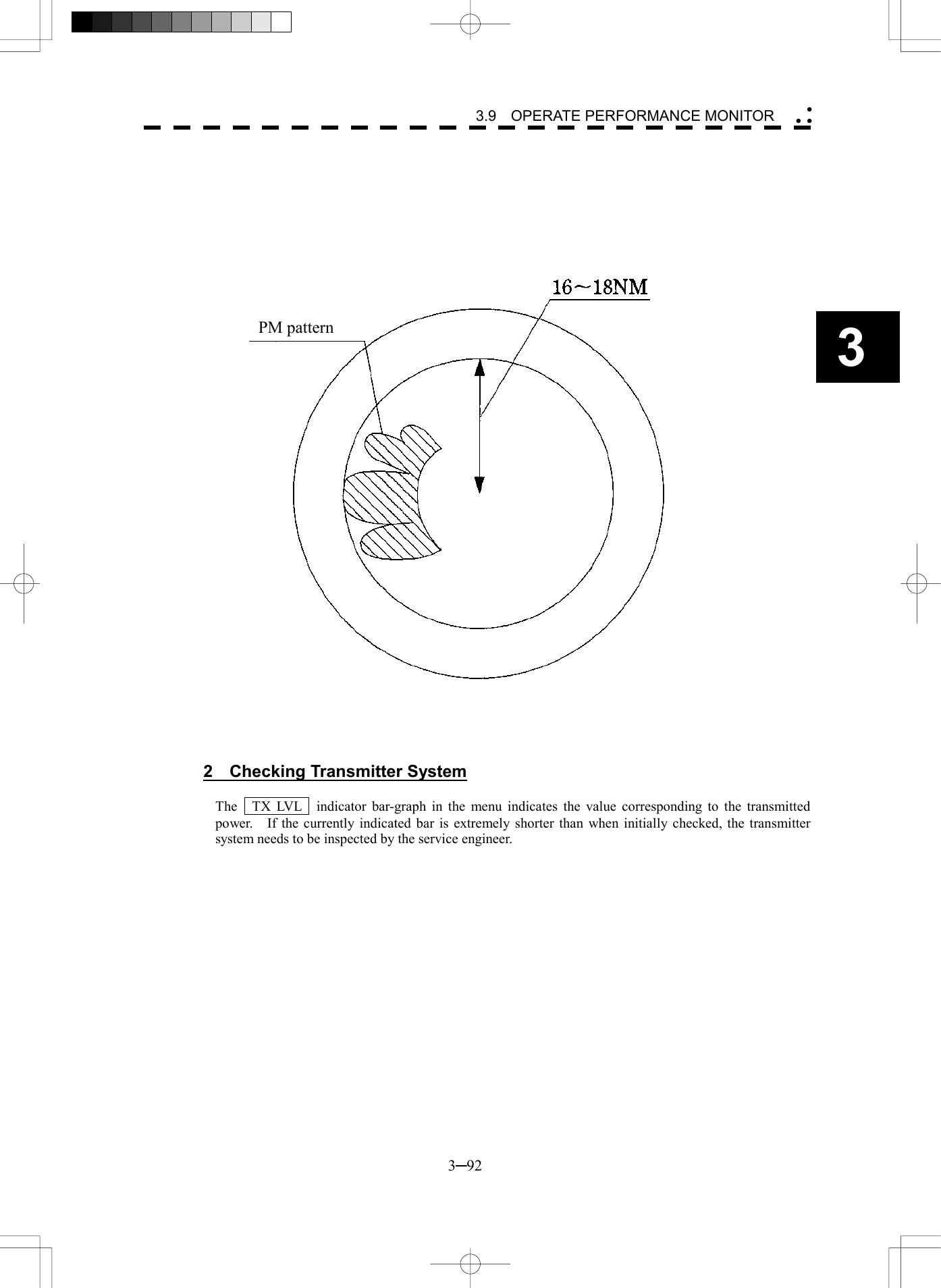
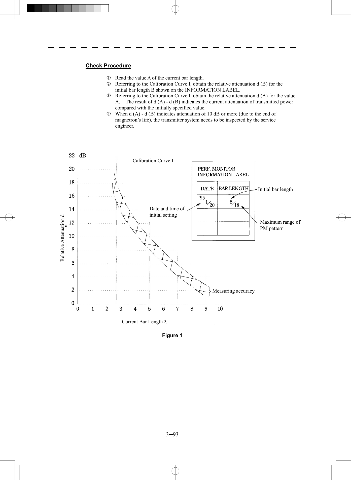
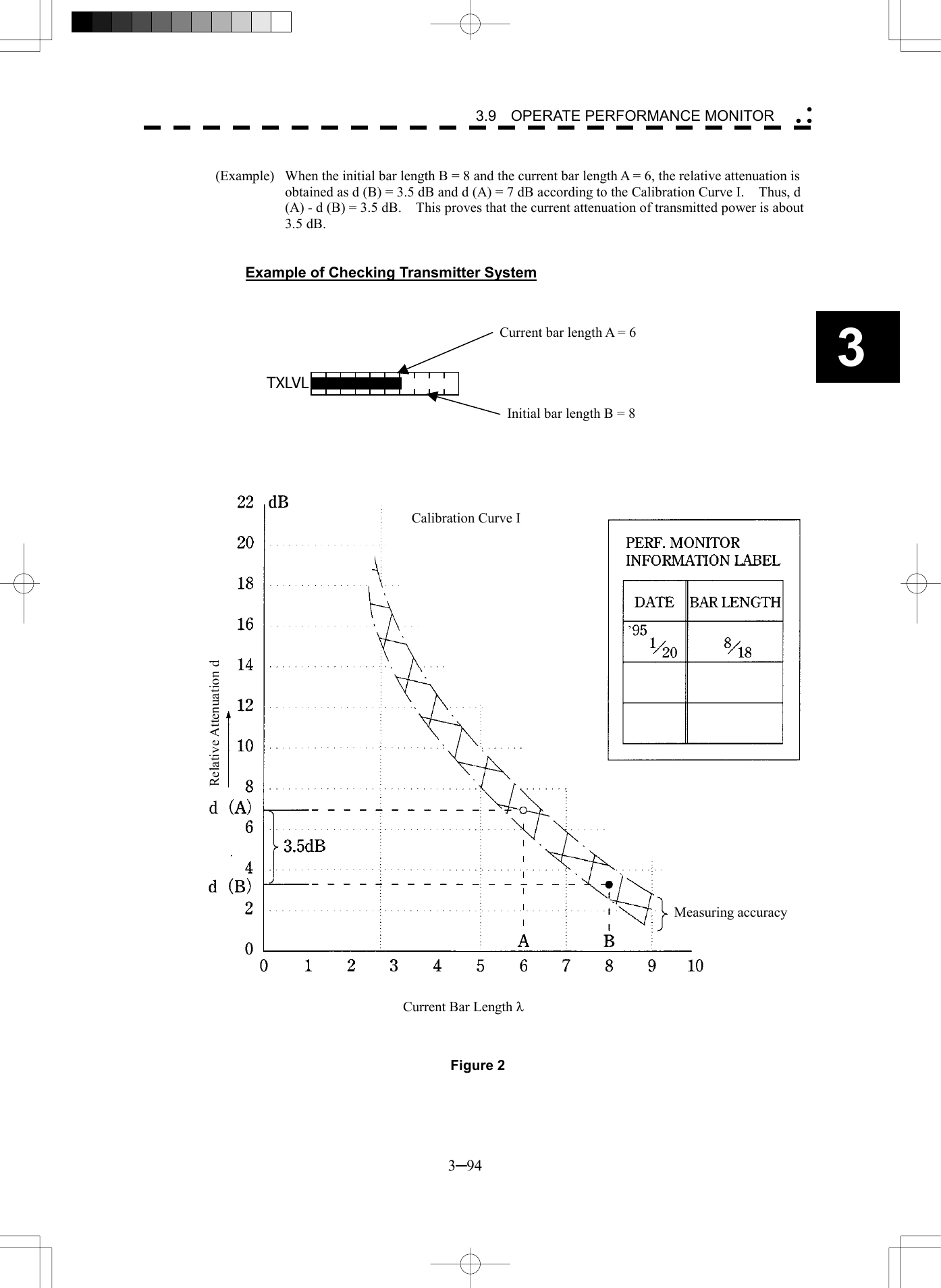
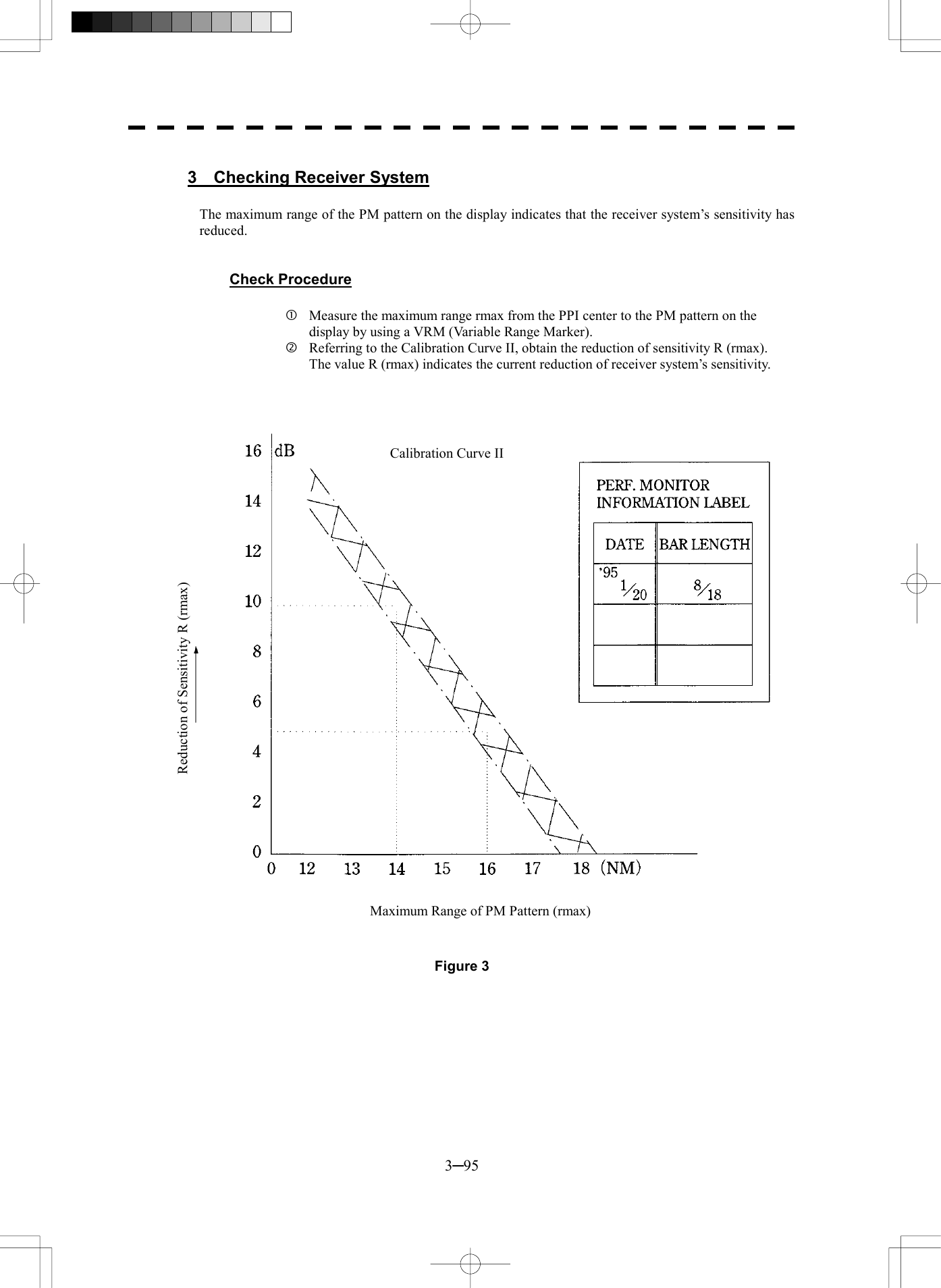
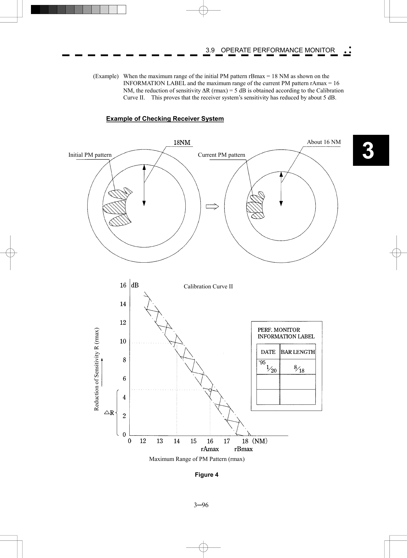
![3─97 3.10 APPLIED OPERATIONS 3.10.1 Set Radar Signal Processing (Process Setting) This function enables the setting of detail information about radar signal processing. Procedures 1 Press [RADAR MENU] key twice. Press [1] key. The Process Setting Menu will appear. Detail information about radar signal processing can be set by changing the settings of the menu items. Note: After the settings for radar signal processing are changed, small targets may not be displayed or unwanted waves may not be suppressed. Thus, do not make a significant change in the settings. [1] Video Latitude · Select the dynamic range in which receiving signals are to be shown on the radar display. · Select NORMAL in standard, and WIDE in rainy weather. · NARROW clearly displays short-range videos when STC is used in manual mode. NORMAL : Standard setting The dynamic range varies depending on the actual range: Short range > long range WIDE : Use this mode when rainy weather intensifies unwanted waves. The dynamic range is about twice as wide as when NORMAL is selected. SUPER WIDE : Use this mode when rain cloud remain at WIDE mode. The dynamic range is about twice as wide as when NORMAL is selected. NARROW : Narrows the dynamic range at short range. Process Setting1. Video LatitudeNORMAL2. Video Noise RejectionLEVEL13. Auto DR ControlON4. Process SwitchOFF5. 2nd Process ModeREMAIN6. Process Switch Range6.2nm7. Fast Target DetectionOFF8. User Function Setting 0. EXIT](https://usermanual.wiki/Japan-Radio/NKE2252.Instruction-manual-1-of-3/User-Guide-482878-Page-164.png)
![3─98 3 3.10 APPLIED OPERATIONS [2] Video Noise Rejection · This function rejects signals that assumed as noise and clutter in radar videos. · Select OFF to display radar videos like analog signals. · Select LEVEL1 or LEVEL2 to suppress noise and clutter. · Select LEVEL1 or LEVEL2 to superimpose-display the chart. OFF : Turns off the noise rejection function, and displays all signals. Targets are popped up from noise and displayed like analog signals. LEVEL1 : Rejects the signals of definitely unwanted waves (noise and clutter). When detection of targets or unwanted waves is not definite, the signals are displayed. When detection of targets is definite, the signals are displayed. LEVEL2 : Rejects the signals of definitely unwanted waves (noise and clutter). When detection of targets or unwanted waves is not definite, the signals are rejected. Only when detection of targets is definite, the signals are displayed. [3] Auto DR Control · This function automatically controls the dynamic range of radar videos when the AUTO SEA/RAIN clutter suppression mode is used. · When the AUTO SEA clutter suppression mode is used, this function improves sensitivity by widening the dynamic range of only areas where sea clutter is strong, and narrowing the dynamic range of areas where sea clutter is not detected. · When the AUTO RAIN clutter suppression mode is used, this function improves sensitivity by widening the dynamic range of areas where sea clutter or rain/snow clutter is strong, and narrowing the dynamic range of the other areas. · Land videos become obscure when the AUTO RAIN clutter suppression mode is used. OFF : Does not control the dynamic range automatically. The dynamic range is set in the same manner as when the MANUAL SEA/RAIN clutter suppression mode is used. ON : Automatically controls the dynamic range. (Standard setting) [4] Process Switch · This function sets a specific area and switches the video process mode between the inside and outside of the area. · In [5] 2nd Process Mode, set the second video process mode for the area outside the boundary. · In [2] PROCESS of Main Menu , set the first video process mode for the area inside the boundary. · Sensitivity at a distance can be improved by suppressing near sea clutter through the correlative process. · There are two methods for setting an area: OFF : Disables the Process Switching function. (Standard setting) RANGE FIX : Sets a boundary at a constant range from the center. Set the boundary range in [6] Process Switch Range. The specific area turns out to be a circle with the own ship’s position as the center. AUTO : Automatically sets a specific area. The area subject to many clutter returns is inside the boundary, and the area less subject to clutter returns is outside the boundary.](https://usermanual.wiki/Japan-Radio/NKE2252.Instruction-manual-1-of-3/User-Guide-482878-Page-165.png)
![3─99 [5] 2nd Process Mode · Set the second video process mode for the outside of a specific area. · This function is enabled when RANGE FIX or AUTO is selected in [4] Process Switching. Video process modes PROC OFF Video process off: Select this mode in general. 3SCAN CORR Correlative process 1: Select this mode when many rain/snow clutter returns are detected. 4SCAN CORR Correlative process 2: Select this mode to highlight targets while suppressing sea clutter returns. 5SCAN CORR Correlative process 3: Select this mode to detect small targets hidden by sea clutter returns. REMAIN Video process 4: Select this mode when own ship yaws wildly. PEAK HOLD Video process 5: Select this mode to detect small targets of which detection probability is low. [6] Process Switch Range · Set the boundary range of a specific area. · This function is enabled when RANGE FIX is selected in [4] Process Switch. · The specific area turns out to be a circle with the own ship’s position as the center. · The boundary range can be set in units of 0.1 nm, ranging 0.1 to 25.5 nm. · After selecting PROC Switch Range, adjust the range using the [MULTI] control. · When finishing the adjustment, press [ENT] key to determine the video process switching range. [7] Fast Target Detection · This function displays fast moving targets that are suppressed in scan-correlative process mode. · This function is enabled when 3SCAN CORR , 4SCAN CORR , or 5SCAN CORR is selected as the video process mode. · If unwanted waves remain on the radar display, suppress them by using the [SEA], [RAIN], or [GAIN] control, or adjusting the interference rejection mode. OFF : Disables the Fast Target Detection function. ON : Enables the Fast Target Detection function.](https://usermanual.wiki/Japan-Radio/NKE2252.Instruction-manual-1-of-3/User-Guide-482878-Page-166.png)
![3─100 3 3.10 APPLIED OPERATIONS 3.10.2 Set Radar Trails (RADAR Trails Setting) This function enables the setting of detail information about radar trails processing. Procedures 1 Press [RADAR MENU] key twice. Press [2] key. The RADAR Tails Setting Menu will appear. Detail information about radar trails processing can be set by changing the settings of the menu items. Note: After the settings for radar trails processing are changed, targets’ trails may not be displayed or trails may be plotted with unwanted waves. Thus, do not make a significant change in the settings. [1] Trails Interval · Set the trail intervals at which radar trails are displayed. · Selection items of trail intervals change depending on the setting of maximum value of radar trail display time. · The Multi-function control is also available for setting. · For the decision branches of trail interval, see Section 3.5.9 on page 3-45. [2] Trails Mode · Set the radar trail display mode. · Each time the button is pressed, you can switch between True and Relative. · For details on the trail mode, see Section 3.5.9 on page 3-45. [3] Trails REF Level · Select a radar video level required for plotting radar trails. · The radar video level increases in order of LEVEL1 ® LEVEL2 ® LEVEL3 ® LEVEL4 . · To plot radar trails with unwanted waves, change to a higher level. · To thin radar trails, change to a higher level. · If radar trails are plotted in snatches, change to a lower level. [4] Trails Reduction · Make a setting for thinning radar trails. · The effect of thinning increases in order of LEVEL1 ® LEVEL2 ® LEVEL3 . · Radar videos do not become obscure because of the thinning of radar trails. OFF : Disables the Trails Reduction function. LEVEL1 : Enables the Trails Reduction function. (Effect: Low) LEVEL2 : Enables the Trails Reduction function. (Effect: Modest) LEVEL3 : Enables the Trails Reduction function. (Effect: High)RADAR Trails Setting1. Trails Interval6 min2. Trails ModeTRUE3. Trails REF LevelLEVEL24. Trails ReductionOFF5. Time/Cont CombineOFF6. Trails ProcessOFF7. Max IntervalSHORT 0. EXIT](https://usermanual.wiki/Japan-Radio/NKE2252.Instruction-manual-1-of-3/User-Guide-482878-Page-167.png)
![3─101 [5] Time/Cont Combine · This function superimpose-displays time radar trails and continuous radar trails. · Operators can distinguish time radar trails from continuous radar trails by setting different colors for both types of trails. OFF : Disables the Time/Cont Combine function. ON : Enables the Time/Cont Combine function. [6] Trails Process · Determine whether to use the video process with radar signals for plotting radar trails. · When Trails Process is ON , radar trails are never plotted with unwanted waves, but the radar trails of fast moving targets may not be plotted. · When Trails Process is OFF , radar trails may be plotted with unwanted waves, but the radar trails of fast moving targets are always plotted. OFF : Disables the Trails Process function. ON : Enables the Trails Process function. [7] MAX Interval · Select the maximum time for displaying radar trails. · Select SHORT when short radar trails are often used in bays and the likes. · Select LONG when long radar trails are necessary for ocean navigation. · MEDIUM is for specification between SHORT and LONG . · Continuous trails are available with all the options. SHORT : Sets 15 minutes as the maximum time for radar trails display. MEDIUM : Sets 30 minutes as the maximum time for radar trails display. LONG : Sets 60 minutes as the maximum time for radar trails display. SUPER LONG : Sets 12 hours as the maximum time for radar trails display.](https://usermanual.wiki/Japan-Radio/NKE2252.Instruction-manual-1-of-3/User-Guide-482878-Page-168.png)
![3─102 3 3.10 APPLIED OPERATIONS 3.10.3 Set Cursor (Cursor Setting) This function enables the setting of detail information about cursor operation and display. Procedures 1 Press [RADAR MENU] key twice. Press [3] key. Press [6] key. The Cursor Setting Menu will appear. Detail information about cursor operation and display can be set by changing the settings of the menu items. [1] EBL/VRM Control CURS (device for cursor operation) · This function is switched between ON and OFF of EBL/VRM Control CRUS function · The trackball is provided as a standard device. If the trackball malfunctions, the cursor can be moved by using the [EBL] control and [VRM] control. · The cursor moves horizontally when [EBL] is operated, and moves vertically when [VRM] is operated. · To switch between EBL/VRM operation and cursor operation while ON is selected, hold down the [EBL] control for 2 seconds. ON: Cursor is operated using a [EBL] [VRM] control. OFF: Cursor is operated using a trackball. [2] Cursor Length · Set the length of the cross cursor mark on the radar display. SHORT : Cuts the cross cursor mark in length. LONG : Makes the cross cursor mark twice as long as when SHORT is selected. Cursor Setting1. EBL/VRM Control CURSOFF2. Cursor LengthLONG 0. EXIT](https://usermanual.wiki/Japan-Radio/NKE2252.Instruction-manual-1-of-3/User-Guide-482878-Page-169.png)
![3─103 3.10.4 Set Screen(Screen Setting) This function enables the setting of detail information about screen display. Procedures 1 Press [RADAR MENU] key twice. Press [4] key. The Screen Setting Menu will appear. Detail information about screen display can be set by changing the settings of the menu items. [3] Numeric NAV INFO · Determine whether to display the numeric values of received navigation information. · The values are displayed in one of three ATA/ARPA’s numeric data display areas. · When the navigation information is displayed, the sizes of the ARPA’s numeric data display areas are exclusively decreased. · Navigation information of the water depth, water temperature, tidal current, wind direction/velocity, and destination is displayed with numeric values. · Numeric NAV INFO is set to ON/OFF each time the OPTION button on the screen is pressed. OFF : Does not display the numeric values of navigation information. AREA1 : Displays the numeric values of navigation information in numeric data display area 1. AREA2 : Displays the numeric values of navigation information in numeric data display area 2. AREA3 : Displays the numeric values of navigation information in numeric data display area 3. Screen Setting1. Display Color Setting2. Brilliance Setting3. Numeric NAV INFOOFF4. Depth Graph Setting5. Wind/Current GraphOFF6. DIR/DIST EXP DisplayOFF 0. EXIT](https://usermanual.wiki/Japan-Radio/NKE2252.Instruction-manual-1-of-3/User-Guide-482878-Page-170.png)
![3─104 3 3.10 APPLIED OPERATIONS [5] Wind/Current Graph · Determine whether to display received wind direction/velocity information with a graph. · The graph is displayed in one of three ATA/ARPA’s numeric data display areas. · When the wind direction/velocity information is displayed, the sizes of the ATA/ARPA’s numeric data display areas are exclusively decreased. · Wind/Current Graph is set to ON/OFF each time the OPTION button on the screen is pressed. OFF : Does not display the wind direction/velocity graph. AREA1 : Displays the wind direction/velocity graph in numeric data display area 1. AREA2 : Displays the wind direction/velocity graph in numeric data display area 2. AREA3 : Displays the wind direction/velocity graph in numeric data display area 3. [6] DIR/DIST EXP Display · Determine whether to expand the value display of cursor, EBL, and VRM. · The value display is expanded in ATA/ARPA’s numeric data display area 3. · When the cursor mark moves on the PPI, the display of cursor information is expanded. · When an EBL or VRM is operated, the value display of each marker is expanded. · The expanded display remains for 5 seconds after the operation of each marker, and then it will disappear. · While the menu is open, any display is not expanded. OFF : Does not expand any display. ON : Expands the display in numeric data display area 3.](https://usermanual.wiki/Japan-Radio/NKE2252.Instruction-manual-1-of-3/User-Guide-482878-Page-171.png)
![3─105 Displaying Water Depth Graph (Depth Graph Setting) · Displays a water depth graph using received water depth information. Procedures 1 Press [RADAR MENU] key twice. Press [4] key. Press [4] key. The Depth Graph Setting Menu will appear. Detail information about screen display can be set by changing the settings of the menu items. [1] Depth Graph Display · Determine whether to display received water depth information with a graph. · The graph is displayed in one of three ATA/ARPA’s numeric data display areas. · When the water depth graph is displayed, the sizes of the ATA/ARPA’s numeric data display areas are exclusively decreased. · Depth Graph Display is set to ON/OFF each time the OPTION button on the screen is pressed. OFF : Does not display a water depth graph. AREA1 : Displays the water depth graph in numeric data display area 1. AREA2 : Displays the water depth graph in numeric data display area 2. AREA3 : Displays the water depth graph in numeric data display area 3. Depth Graph Setting1. Depth Graph DisplayOFF2. Depth Range50 m3. Time Range10 min 0. EXIT](https://usermanual.wiki/Japan-Radio/NKE2252.Instruction-manual-1-of-3/User-Guide-482878-Page-172.png)
![3─106 3 3.10 APPLIED OPERATIONS [2] Depth Range · Select the depth range on the water depth graph. 50m : Sets 50 m as the depth range. 100m : Sets 100 m as the depth range. 250m : Sets 250 m as the depth range. AUTO : Uses the depth range in the DPT sentence included in received data. [3] Time Table · Select the time range on the water depth graph. 10min : Sets 10 minutes as the time range. 15min : Sets 15 minutes as the time range. 30min : Sets 30 minutes as the time range. 60min : Sets 60 minutes as the time range. Depth rangeTime range](https://usermanual.wiki/Japan-Radio/NKE2252.Instruction-manual-1-of-3/User-Guide-482878-Page-173.png)
![3─107 3.10.5 Set Scanner (TRX Setting) This function enables the setting of detail information about a scanner Procedures 1 Press [RADAR MENU] key twice. Press [5] key. The TRX Setting Menu will appear. Detail information about antenna operation can be set by changing the settings of the menu items. [1] PRF Fine Tuning · Fine-tune the transmitting repetition frequency of the transmitter in the range 90 to 100%. · If radar’s interference patterns are concentrically displayed, increment or decrement the set value by 3 to 4 in order to heighten the effect of interference rejection. · The same operation can be performed by pressing the [TX/STBY] key several times. · One of 32 levels 0-31 can be set. [2] Jamming · Use the jamming function to control the transmitting repetition frequency of the transmitter. · This function is effective when interference patterns caused by radar equipment of the same model do not disappear. OFF : Disables the jamming function. ON : Enables the jamming function. [3] XMIT Repitation FREQ · Select the operation mode the transmitting repetition frequency of the transmitter. NORMAL Standard mode: Both appropriate sensitivity and magnetron’s life expectancy are maintained. ECONOMY Power saving mode: Sensitivity slightly lowers, but the service life of magnetron is prolonged when short pulses are used. HI POWER High sensitivity mode: Sensitivity improves when long pulses are used, but the service life of magnetron is slightly shortened. TRX Setting1. PRF Fine Tuning02. JammingOFF4. XMIT Repitation FREQ 6. Band Select 0. EXIT NORMAL](https://usermanual.wiki/Japan-Radio/NKE2252.Instruction-manual-1-of-3/User-Guide-482878-Page-174.png)
![3─108 3 3.10 APPLIED OPERATIONS [6] Band Select · Select band of antenna. This item is effective only when the antenna in connection supports two frequencies. X-Band : Selects the X-band side from the two frequencies. S-Band : Selects the S-band side from the two frequencies. X/S-band : Supports the two frequencies.](https://usermanual.wiki/Japan-Radio/NKE2252.Instruction-manual-1-of-3/User-Guide-482878-Page-175.png)
![3─109 3.10.6 Set Chart Display (Map Setting) This function enables the setting of detail information about chart display. Setting JRC/ERC Chart Display (JRC/ERC Setting) Procedures 1 Press [RADAR MENU] key twice. Press [9] key. Press [5] key. Press [3] key. The JRC/ERC Setting Menu will appear. Detail information about the colors and brilliance of JRC/ERC chart display can be set by changing the settings of the menu items. The data of colors and brilliance can be stored for each day/night mode. [1] Day/Night · Select a desired display mode before setting the colors and brilliance of chart display. · There are four selection items: DAY1 , DAY2 , NIGHT1 , and NIGHT2 . [2] Color of Land · Select the color of land display. · There are four selection items: BROWN , YELLOW , GREEN , and WHITE . [3] Bright of Land · Select the brilliance of land display. · There are three selection items: LOW , MEDIUM , and HIGH . JRC/ERC Setting1. Day/NightDAY12. Color of LandYELLOW3. Bright of LandHIGH4. Color of SeaBLUE5. Bright of SeaHIGH6. Color of NameWHITE7. Bright of NameHIGH 9. Next Page0. EXIT](https://usermanual.wiki/Japan-Radio/NKE2252.Instruction-manual-1-of-3/User-Guide-482878-Page-176.png)
![3─110 3 3.10 APPLIED OPERATIONS [4] Color of Sea · Select the color of sea display. · There are four selection items: GRAY , CYAN , BLUE , and GREEN . [5] Bright of Sea · Select the brilliance of sea display. · There are four selection items: OFF , LOW , MEDIUM , and HIGH . [6] Color of Name · Select the color of a location name. · There are eight selection items: BLACK , WHITE , CYAN , BLUE , GREEN , YELLOW , PINK , and RED . [7] Bright of Name · Select the brilliance of location name display. · There are four selection items: OFF , LOW , MEDIUM , and HIGH . [9] Next Page · Moves to the next page. · The next page of the JRC/ERC Setting Menu will appear. [1] LAT/LON Line · Select the mode to display latitude and longitude lines. · There are two selection items: LINE NUM : Displays both latitude/longitude lines and values indicating the latitude and longitude. NUM : Displays only the values indicating the latitude and longitude. [2] Color of L/L Line · Select the colors that are to represent latitude and longitude lines. · There are eight selection items: BLACK , WHITE , CYAN , BLUE , GREEN , YELLOW , PINK , and RED . JRC/ERC Setting1. LAT/LON LineLINE NUM2. Color of L/L LineBLUE3. Bright of L/L LineHIGH4. ERC Display RequestON5. ERC MarkSMALL6. JRC Card Display Setting 0. EXIT](https://usermanual.wiki/Japan-Radio/NKE2252.Instruction-manual-1-of-3/User-Guide-482878-Page-177.png)
![3─111 [3] Bright of L/L Line · Select the brilliance of latitude/longitude line display. · There are four selection items: OFF , LOW , MEDIUM , and HIGH . [4] ERC Display Request · Display of the information within ERC can be switched between ON and OFF . · There are two selection items: ON , and OFF . [5] ERC Mark · Select the size of mark display on the ERC chart. · There are two slection items: NORMAL and SMALL . [6] JRC Card Display · Sets the display contents of the JRC card. · The JRC Card Display Setting Menu will appear. [1] Light House · Determine whether to display lighthouses. · There are two selection items: ON and OFF . [2] Buoy · Determine whether to display buoys. · There are two selection items: ON and OFF . [3] Rough Line · Determine whether to display rough lines. · There are two selection items: ON and OFF . [4] Other Line · Determine whether to display other lines. · There are two selection items: ON and OFF . JRC Card Display Setting1. Light HouseON2. Buoy ON3. Rough LineON4. Other LineON 0. EXIT](https://usermanual.wiki/Japan-Radio/NKE2252.Instruction-manual-1-of-3/User-Guide-482878-Page-178.png)
![3─112 3 3.10 APPLIED OPERATIONS Setting Contour Lines on JRC Chart (Contour Setting) Procedures 1 Press [RADAR MENU] key twice. Press [9] key. Press [5] key. Press [4] key. The Contour Setting Menu will appear. Depths and display colors can be set for 9 contour lines in total: 8 for depth specification and 1 for other depths. 2 Select the number of depth to be changed, pressing the numeric key. The depth input screen will appear. Enter the value as the depth to be set. Subsequently, the display line list will appear. 3 Select the number of display line to be set, pressing the numeric key. Subsequently, the display color list will appear. 4 Select the number of display color to be set, pressing the numeric key. The selected color to represent the contour lines of the depth will be set. To change the settings of other depths, repeat steps 2 and 3. Contour Setting1. 10m -- GREEN2. 20m -- BLUE3. 30m -- BLUE4. 40m -- BLUE5. 50m -- BLUE6. 60m -- BLUE7. 70m -- BLUE8. 80m -- BLUE9. Other -- BLUE0. EXIT 1-99: 100-999: 1000-9999:](https://usermanual.wiki/Japan-Radio/NKE2252.Instruction-manual-1-of-3/User-Guide-482878-Page-179.png)
![3─113 Set C-MAP Display Procedures 1 Press [RADAR MENU] key twice. Press [9] key. The Plot Menu will appear. 2 Press [5] key. The MAP Setting Menu will appear. 3 Press [2] key. The C-MAP Setting Menu will appear. [1] Grid Display · Sets whether or not latitudinal longitudinal lines are displayed with C-MAP. · Each time you press [1] key, the grid display item is switched between ON and OFF. · ON: Displayed OFF: Not displayed [2] Sounding Display · Sets whether or not soundings values are displayed with C-MAP. · Each time you press [2] key, the souding display item is switched between ON and OFF. · ON: Displayed OFF: Not displayed C-Map Setting1. Grid DisplayON2. Sounding DisplayON3. Sounding UnitFEET4. Light Sectors DisplayON5. Light Sectors LevelH0. EXIT](https://usermanual.wiki/Japan-Radio/NKE2252.Instruction-manual-1-of-3/User-Guide-482878-Page-180.png)
![3─114 3 3.10 APPLIED OPERATIONS [3] Sounding Unit · Sets the units when soundings values are displayed with C-MAP. · Press [3] key to display a list of units. · 1: FEET 2: FATHOM 3: METERS 4: DECIMAL FATHOM You can select one from the above four items. Select the item you want to set, pressing the numeric keys [1] to [4]. [4] Light Sectors Display · Sets whether or not the light sectors are displayed. · Each time you press [4] key, the light sectors display item is switched between ON and OFF. · ON: Displayed OFF: Not displayed [5] Light Sectors Level · Sets levels when light sectors are displayed with C-MAP. · Press [5] key to display a list of levels. · Selects one from level settings A to H.](https://usermanual.wiki/Japan-Radio/NKE2252.Instruction-manual-1-of-3/User-Guide-482878-Page-181.png)
![3─115 Correcting Chart Position (Map Display Setting) Procedures 1 Press [RADAR MENU] key twice. Press [9] key. Press [5] key. Press [5] key. The Map Display Setting Menu will appear. There are three methods for correcting the chart position. [1] Shift Coast Line 1 Set the correction value by operating the cursor. 1 Press [1] key while the Map Display Setting Menu is open. 2 Move the cursor to the chart on which a position is to be corrected, and press [ENT] key. 3 Move the cursor to the radar video of which position is to be corrected, and press [ENT] key. SETTING (correcting) will be indicated for Shift Coast Line 1. At this time, MAP SHIFT will appear at the radar display button 29 on page 2-7, indicating that the position is being corrected. Cancellation of Shift Coast Line 1 1 Press [1] key while the MAP Display Setting Menu is open. DELETE (no correction) will be indicated for Shift Coast Line 1. At this time, MAP SHIFT will disappear from the lower right of the radar display. Map Display Setting1. Shift Coast Line 1SETTING2. Shift Coast Line 2N0.000’E0.000’3. LAT/LON CorrectionN0.000’E0.000’N 35°00.000’E140°00.000’5. LORAN C Correction 0. EXIT 4. MAP Center Position6. LORAN A Correction](https://usermanual.wiki/Japan-Radio/NKE2252.Instruction-manual-1-of-3/User-Guide-482878-Page-182.png)
![3─116 3 3.10 APPLIED OPERATIONS [2] Shift Coast Line 2 Set a correction value pressing the numeric values. A correction value can be entered in the range -9.999’ to +9.999’. 1 Press [2] key while the Map Display Setting Menu is open. The chart position correction value input screen will appear. 2 Enter the correction value for the latitudinal direction, pressing the numeric keys. To switch between the north and south, turn the [MULTI] control. 3 Press [ENT] key. The correction value for the latitudinal direction will be determined. 4 Enter the correction value for the longitudinal direction, pressing the numeric keys. To switch between the east and west, turn the [MULTI] control. 5 Press [ENT] key. The correction value for the longitudinal direction will be determined. At this time, MAP SHIFT will appear at the radar display button 29 on page 2-7, indicating that the position is being corrected. Cancellation of Shift Coast Line 2 1 Press [2] key while the MAP Display Setting Menu is open. The chart position correction value input screen will appear. 2 Press [0] key, and then [ENT] key. The correction value for the latitudinal direction will be set to 0. 3 Press [0] key, and then [ENT] key. The correction value for the longitudinal direction will be set to 0. At this time, MAP SHIFT will disappear from the lower right of the radar display.](https://usermanual.wiki/Japan-Radio/NKE2252.Instruction-manual-1-of-3/User-Guide-482878-Page-183.png)
![3─117 [3] LAT/LON Correction This method corrects a chart position by changing the values of latitude and longitude that are sent by the navigation equipment. Only our service engineers are to use this correction method because the contents of data such as trails data to be saved are changed when the method is used. A correction value can be entered in the range -9.999’ to +9.999’. 1 Press [3] while the MAP Display Setting Menu is open. The latitude/longitude correction value input screen will appear. 2 Enter the correction value for the latitudinal direction, pressing the numeric keys. To switch between the north and south, turn the [MULTI] control. 3 Press [ENT] key. The correction value for the latitudinal direction will be determined. 4 Enter the correction value for the longitudinal direction, pressing the numeric keys. To switch between the east and west, turn the [MULTI] control. 5 Press [ENT] key. The correction value for the longitudinal direction will be determined. Cancellation of LAT/LON Correction 1 Press [3] key while the MAP Display Setting Menu is open. The latitude/longitude correction value input screen will appear. 2 Press [0] key, and then [ENT] key. The correction value for the latitudinal direction will be set to 0. 3 Press [0] key, and then [ENT] key. The correction value for the longitudinal direction will be set to 0.](https://usermanual.wiki/Japan-Radio/NKE2252.Instruction-manual-1-of-3/User-Guide-482878-Page-184.png)
![3─118 3 3.10 APPLIED OPERATIONS [4] MAP Center Position This method corrects a chart position by entering the values of latitude and longitude at own ship’s position in manual mode. If latitude and longitude data sent by the navigation equipment has been entered, the data has priority over the manually entered values. 1 Press [4] key while the MAP Display Setting Menu is open. The latitude/longitude correction value input screen will appear. 2 Enter the value as latitudinal, pressing the numeric keys. To switch between the north latitude and south latitude, turn the [MULTI] control. 3 Press [ENT] key. The entered value will be determined as latitude. 4 Enter the value as longitude, pressing the numeric keys. To switch between the east longitude and west longitude, turn the [MULTI] control. 5 Press [ENT] key. The entered value will be determined as longitude.](https://usermanual.wiki/Japan-Radio/NKE2252.Instruction-manual-1-of-3/User-Guide-482878-Page-185.png)
![3─119 3.10.7 Set LORAN C (LORAN C Correction) This function enables LORAN C time difference display for the own ship’s position and cursor position. Setting LORAN C Procedures 1 Press [RADAR MENU] key twice. Press [9] key. Press [5] key. Press [5] key. Press [5] key. The LORAN C Correction Menu will appear. The chain and time difference for LORAN C time difference display can be set by changing the settings of the menu items. [1] Chain · Set the chain. · Enter the value in the range 0000 to 9999 by using the numeric keys. · Only a value in the table can be entered. [2] TD1, [3] TD2 · Enter the TD value for slave station 1/2. [4] TD1 Correction, [5] TD2 Correction · Enter the sound velocity time correction value for the TD value of slave station 1/2. LORAN C Correction1. Chain 99702. TD1 133. TD2 584. TD1 Correction0.1 uS5. TD2 Correction0.2 uS 0. EXIT](https://usermanual.wiki/Japan-Radio/NKE2252.Instruction-manual-1-of-3/User-Guide-482878-Page-186.png)
![3─120 3 3.11 USE FUNCTION SWITCH [FUNC] “Radar Function Setting” is provided for always obtaining the best radar video by storing complex radar signal processing settings in the optimum status by use, and calling the setting in accordance with the conditions for using the function. Functions are factory-set for general use, and the settings can be fine adjusted by operating the menu. Four function modes are available, and they are factory-set as follows: Function 1: COAST Useful for observing short-range videos Function 2: DEEP SEA Suitable for general ocean navigation Function 3: FISH NET Useful for small target. Function 4: STORM Useful for observing videos in stormy weather 3.11.1 Operation Procedures Calling a Function Procedures 1 Press the [FUNC] key. Each time the [FUNC] key is pressed, the selection changes cyclically as follows: Function Off ® Function 1 ® Function 2 ® Function 3 ® Function 4 ® Function Off The currently called function mode will be indicated at the lower left of the radar display. * Switching can be done each time button 13 on the radar display on page 2-7 is pressed. Changing Function Setting (temporary change) · When radar signal processing setting is changed by using the menu or button on the radar display while function 1 to 4 is called, the change is temporarily reflected to the operating state. · Since this method does not change the memory contents, the new setting is deleted as soon as another function is called. · When the previous function is called again, operation is performed according to the memory contents. Changing Function Setting (memory contents change) · To change the memory contents of functions 1 to 4, use the function setting menu. · To display the function setting menu, press [RADAR MENU] twice, [1] key, and then [8] key. · Press the numeric key corresponding to the target function number. · The function setting menu consists of five pages. To switch between the pages, select [0] key Previous Page or [9] key Next Page.](https://usermanual.wiki/Japan-Radio/NKE2252.Instruction-manual-1-of-3/User-Guide-482878-Page-187.png)
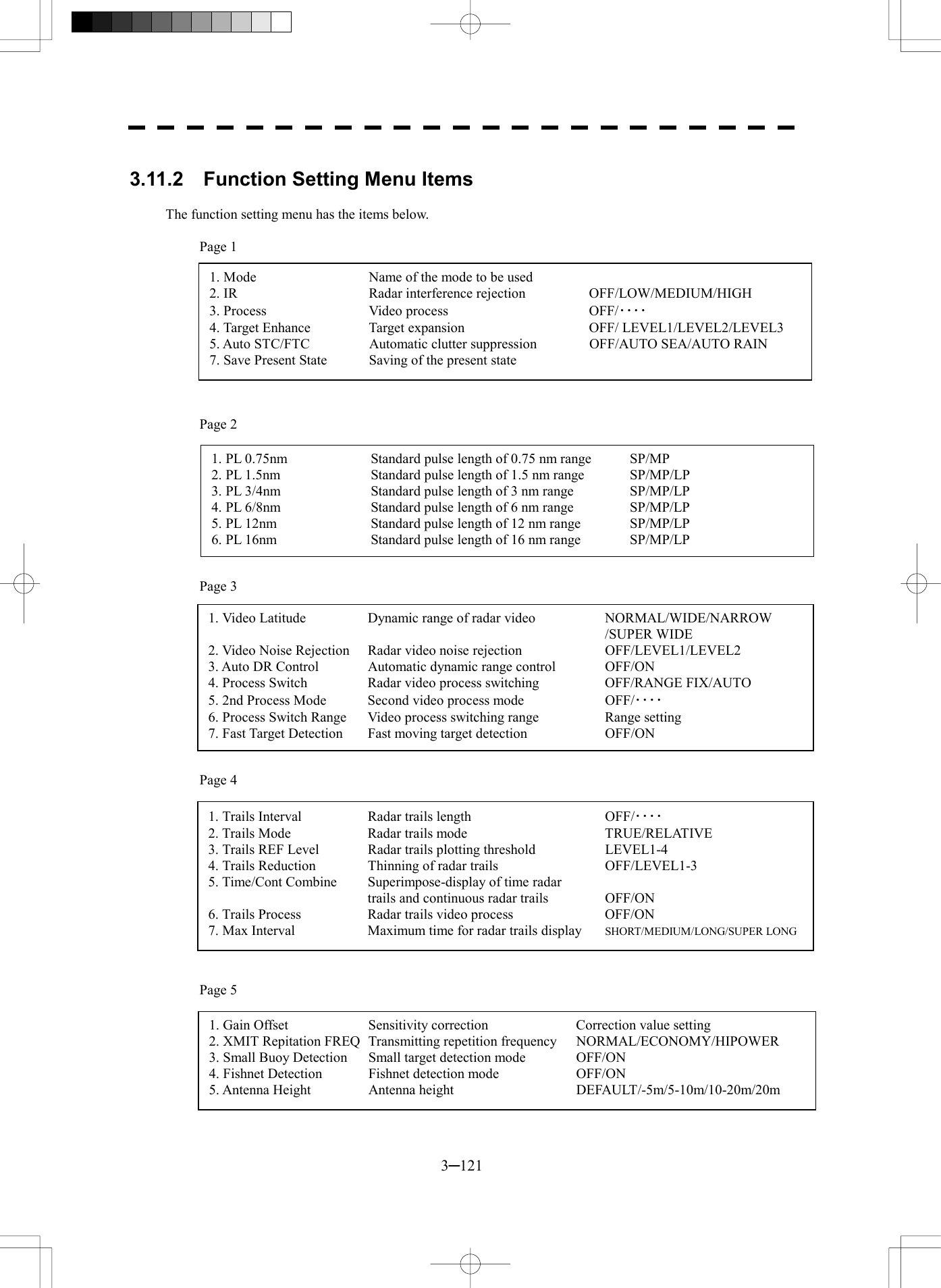
![3─122 3 3.11 USE FUNCTION SWITCH 3.11.3 Overview of Function Operations The following outlines the operation of each function selected from the function setting menu: [Page 1] [1] MODE (Mode) · Selects the function name to be indicated at the lower left of the radar display when the function is selected. · When the setting is changed back to the factory setting, the initial value of the selected mode is called. · The following 11 modes are provided: COAST: Use this mode to monitor a relatively short range, for example, bays and coasts where many boats and ships are running. (Importance is attached to resolution.) DEEPSEA: Use this mode to monitor a relatively long range, for example, the open sea. (Importance is attached to long-range sensitivity.) FISHNET: Use this mode to detect small targets such as fishnets of round haul netters hidden by sea clutter returns. (Importance is attached to sea clutter suppression, and sensitivity to moving targets lowers.) STORM: Use this mode when many rain/snow clutter returns or sea clutter returns are detected in stormy weather. (Importance is attached to rain/snow clutter and sea clutter suppression, and sensitivity slightly lowers.) CALM: Use this mode when only a few rain/snow clutter returns or sea clutter returns are detected. RAIN: Use this mode when sea clutter is not strong but rain/snow clutter is strong. (Importance is attached to rain/snow clutter suppression, and sensitivity slightly lowers.) BIRD: Use this mode to detect tens of seabirds at low altitude during coastal navigation or hundreds of seabirds at high altitude during ocean navigation. LONG: Use this mode to detect small targets at relatively long distance in the open sea. BUOY: Use this mode to detect small targets like radio buoys in areas outside the sea clutter area. (This mode displays targets of which detection probability is low.) USER1: General mode used when the nine modes above are not applicable USER2: General mode used when the nine modes above are not applicable [Page 1] [2] IR (radar interference rejection) · Same function as IR in the Main Menu [Page 1] [3] Process (video process) · Same function as PROCESS in the Main Menu [Page 1] [4] Target Enhance · Same function as TARGET ENHANCE in the Main Menu](https://usermanual.wiki/Japan-Radio/NKE2252.Instruction-manual-1-of-3/User-Guide-482878-Page-189.png)
![3─123 [Page 1] [5] Auto SEA/RAIN (Auto STC/FTC) · Detects unwanted waves such as rain/snow clutter and sea clutter and automatically suppresses them. · When the sea state or weather changes, this function automatically performs suppression processing in accordance with the situation. · Suppression processing is not full automatic, and requires the operator to control the afterimages of unwanted waves. · To control the afterimage of sea clutter, use the [SEA] control. · To control the afterimage of rain/snow clutter, use the [RAIN] control. · In areas where the density of unwanted waves is low, unwanted waves may remain being judged as targets. Thus, use the automatic clutter suppression mode together with the video process mode. · Characteristics of the automatic clutter suppression function: OFF: Disables the automatic clutter suppression function. Select OFF when rain/snow clutter and sea clutter are not strong or when the ship is in a bay. AUTO SEA: Automatically detects the strength of sea clutter, and performs the most suitable sea clutter suppression processing. Even when the strength of sea clutter varies depending on the wind direction, AUTO SEA performs the most suitable suppression processing. Land like islands can be displayed naturally. Since rain clouds outside sea clutter areas are recognized as land, there is no effect of suppressing rain/snow clutter. AUTO RAIN: Along with AUTO SEA, AUTO RAIN automatically detects the strength of rain/snow clutter, and performs the most suitable rain/snow clutter suppression processing. When rain clouds are scattered about, AUTO RAIN performs rain/snow clutter suppression processing for only the rain-cloud areas. Since land is recognized as rain clouds, land videos become obscure. [Page 2] [1]-[7] PL (Pulse Width) · Sets the standard transmitter pulse length in each range. · When the range is called, the pulse range is used. [Page 3] [1]-[7] Radar signal processing settings (Process Setting) · Same functions as those in the Process Setting Menu generally used [Page 4] [1]-[7] Radar trails settings (Trails Setting) · Same functions as in the Trails Setting of the RADAR Menu generally used](https://usermanual.wiki/Japan-Radio/NKE2252.Instruction-manual-1-of-3/User-Guide-482878-Page-190.png)
![3─124 3 3.11 USE FUNCTION SWITCH [Page 5] [1] Gain Offset · Corrects sensitivity while the function mode is called. · Since the displayed noise level varies depending on the combination of the video process mode and the interference rejection level, sensitivity needs fine adjustment for always obtaining the highest level. · The sensitivity correction function saves the correction value set by the sensitivity control in each function mode, so it can obtain the highest sensitivity without the sensitivity control being operated when the function mode is changed. · To set high sensitivity, set a value on the “+” side. · To set low sensitivity, set a value on the “-” side. · When the radar interference rejection level is increased, the noise level is lowered. Thus, set a sensitivity correction value to the “+” side. · When the video process mode 3SCAN CORR, 4SCAN CORR, or 5SCAN CORR is used, the noise level is lowered. Thus, set a sensitivity correction value to the “+” side. · When the video process mode REMAIN or PEAK HOLD is used, noise is hard to disappear. Thus, set a sensitivity correction value to the “-” side. [Page 5] [2] XMIT Repitation FREQ. · Same function as in the TRX Setting of the RADAR Menu generally used [Page 5] [3] Small Buoy Detection · Reduces the loss of signal processing during detection of small targets. OFF: Activates the general signal processing mode. ON: Activates the small buoy detection mode that reduces the loss of signal processing. [Page 5] [4] FishNet Detection · Use this mode to detect small targets hidden by sea clutter returns. · This function becomes more effective when the AUTO RAIN clutter suppression function is used together. OFF: Activates the general signal processing mode. ON: Activates the fishnet detection mode.](https://usermanual.wiki/Japan-Radio/NKE2252.Instruction-manual-1-of-3/User-Guide-482878-Page-191.png)
![3─125 3.11.4 Overview of Stored Function Setting Data The overview of stored function setting data is as follows: · Factory-set data: Stored data that general operation cannot change · Default data: Standard data of each function mode that users can change · Data that can be called: Stored data that can be called by pressing the [FUNC] key [Page 1] [1] Call Mode · Calls the standard setting of the mode, and stores it for the function number. [Page 1] [6] Save Present State · The currently operating state can be stored for the function number. · Use this function to store the state of good setting that will be frequently used. [Page 5] [7] Save Default of Mode · Stores the setting of the current function number, as the default setting of the mode. [Page 5] [8] Initialization · Changes the memory contents of the mode, which is used with the current function number, back to the factory setting. COAST DEEPSEA FISHNET STORM CALM RAIN BIRD LONG BUOY USER1 USER2 COAST DEEPSEA FISHNET STORM CALM RAIN BIRD LONG BUOY USER1 USER2 FUNC1 FUNC2 FUNC3 FUNC4 PRESENT [5]-[8] [1]-[1] [5]-[7] [FUNC][1]-[7] Function Setting Factory-set data Function Setting Default data Function Setting Data that can be called Current data](https://usermanual.wiki/Japan-Radio/NKE2252.Instruction-manual-1-of-3/User-Guide-482878-Page-192.png)
![3─126 3 3.11 USE FUNCTION SWITCH Load PIN Data1. 2. 3. 4. 5. 0. EXIT3.11.5 Personal Information (PIN Setting) The operation status of the radar is recorded. If the system is operated by more than one operator, the operators can register operation status as suitable for them and call the status. Operation status for up to five operations can be registered, and a name can be assigned to each status. (Up to 10 alphanumeric characters) * Data stored as personal information · Day/Night mode setting · Brilliance · Alarm volume · Vector length/mode · Various types of image processing (IR, ENH, PROC, FUNC) [1] Calling Operation Status (Load PIN Data) Procedures 1 Press [RADAR MENU] key twice. Press [8] key. The Radar Sub Menu will appear. 2 Press [1] key. The PIN Setting Menu will appear. 3 Press [1] key. The Load PIN Data Menu will appear. 4 Select the item you want to load, pressing the numeric keys [1] to [5]. The Load Execution Check Menu will appear. Select “Yes” for loading. Exit 1 Press [RADAR MENU] key. The Target Information Display Menu will reappear.](https://usermanual.wiki/Japan-Radio/NKE2252.Instruction-manual-1-of-3/User-Guide-482878-Page-193.png)
![3─127 Save PIN Data1. 2. 3. 4. 5. 0. EXIT [II] Saving Operation Status (Save PIN Data) Procedures 1 Press [RADAR MENU] key twice. Press [8] key. The Radar Sub Menu will appear. 2 Press [1] key. The PIN Setting Menu will appear. 3 Press [2] key. The Save PIN Data Menu will appear. 4 Select the number corresponding to the place where you want to save status, pressing the numeric keys [1] to [5]. The Code Input Menu will appear. 5 Using numeric key, enter the name and then press [ENT] key. Data will be saved with the entered name. Exit 1 Press [RADAR MENU] key. The Target Information Display Menu will reappear. 1 2 34 5 6 7 8 90 B C DE F G H I JA L M N O P Q R S TK V W X Y Z SP < >U DEL ENT BS Save PIN DataEXIT](https://usermanual.wiki/Japan-Radio/NKE2252.Instruction-manual-1-of-3/User-Guide-482878-Page-194.png)
![3─128 3 3.11 USE FUNCTION SWITCH [III] Erasing Registered Operation Status (Delete PIN Data) Procedures 1 Press [RADAR MENU] key twice. Press [8] key. The Radar Sub Menu will appear. 2 Press [1] key. The PIN Setting Menu will appear. 3 Press [3] key. The Delete PIN Data Menu will appear. 4 Select the file you want to erase, pressing the numeric keys [1] to [5]. The Delete Execution Check Menu will appear. Select “Yes” for deletion. Exit 1 Press [RADAR MENU] key. The Target Information Display Menu will reappear. Delete PIN Data1. 2. 3. 4. 5. 0. EXIT](https://usermanual.wiki/Japan-Radio/NKE2252.Instruction-manual-1-of-3/User-Guide-482878-Page-195.png)
![3─129 Plot Menu1. Own Track Setting5. Map Setting6. MEM CAPA/Copy7. CLR MEM INIT Card0. EXIT3.12 USING CARD This radar has two card slots. Inserting a flash memory card (option) into a card slot, you can save the following contents, saved in the processor, in the card or can read data from the card to the processor. · Trails of own ship: 7000 points maximum · Track of other ship: 20 target×1500 points · Mark Line (including mark lines created by user map): 20000 points maximum (plotter option) · Waypoint: 99 points maximum (plotter option) · Route: 10 routes maximum (plotter option) These pieces of information can be saved in a flash memory card as a file. The internal capacity is as large as only a file. An internally created file can be saved until the flash memory card is full. 3.12.1 Save in and Transfer to Card (MEM CAPA/Copy) Procedures 1 Press [RADAR MENU] key twice. The Radar Menu will appear. 2 Press [9] key. The Plot Menu will appear. * Button 56 on the radar display on page 2-7 is also available to save and transfer data. 3 Press [6] key. The MEM CAPA/Copy window will appear.](https://usermanual.wiki/Japan-Radio/NKE2252.Instruction-manual-1-of-3/User-Guide-482878-Page-196.png)
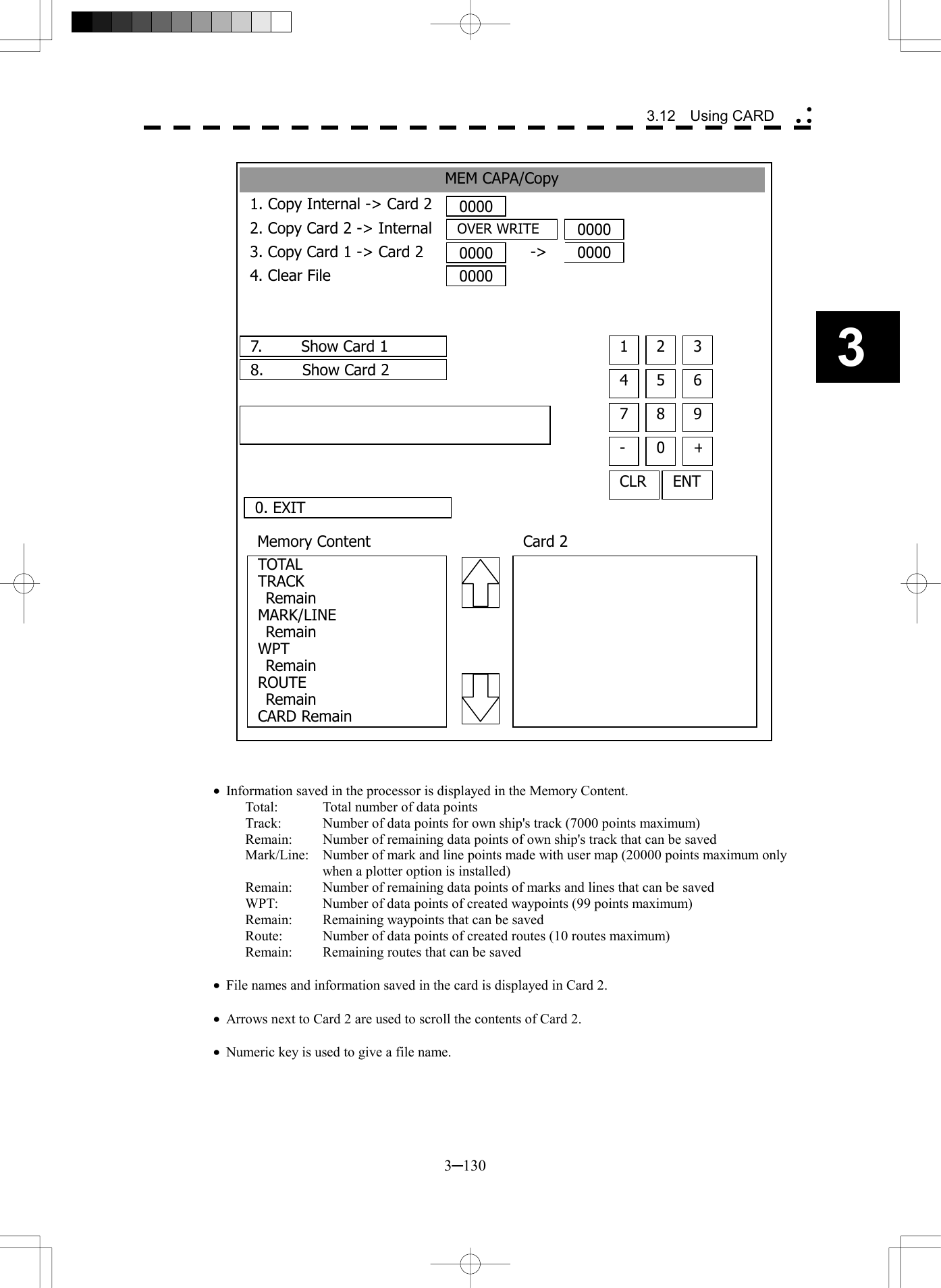
![3─131 [I] Copy Internal Information to Card 2 (Copy Internal ® Card 2) Procedures 1 Press [1] key while the CAPA/Copy Menu is open. A file name to copy Internal information to Card 2 can be entered. 2 Using the numeric key, enter a file name. After enter a file name, select ENT.CLR will be cancelled. The system writes internal information into Card 2 with an entered number used as a file name. The capacity of information that can be saved in the internal portion is limited to the maximum number of points in items described on the previous page. For the capacity of information that can be saved in a card, the system can save information in a card until the card capacity is filled with a file, counting the information saved in the internal portion as a file. [II] Read Information from Card 2 to Internal Portion(Copy Card 2 ® Internal) Procedures 1 Press [2] key while the CAPA/Copy Menu is open. A file name to copy information from Internal portion to Card 2 can be entered. Read the file name displayed in the Card 2 window. 2 Using the numeric key, enter a file name. After having enter the name, select ENT.CLR will be cancelled. The entered file name is read from Card 2 to the internal portion. When information is to be transferred from Card 2 to the internal portion in the ADD mode, the information can be copied from multiple files. However, information cannot be read when the number of points for an item has reached the maximum. In the ADD mode, the WPT and Route are overwritten. [III] Copy Information from Card 1 to Card 2 (Copy Card 1 ® Card 2) Procedures 1 Press [3] key while the CAPA/Copy Menu is open. A file name to copy information from Card 1 to Card 2 can be entered. 2 Using the numeric key, enter a file name. Using the numeric key, euter a file name to be copied. After having enter the name, select ENT. CLR will be cancelled. 3 Using the numeric key, enter a file name to copy. After having enter the name, select ENT.CLR will be cancelled. The entered file number is copied from Card 1 to Card 2.](https://usermanual.wiki/Japan-Radio/NKE2252.Instruction-manual-1-of-3/User-Guide-482878-Page-198.png)
![3─132 3 3.12 Using CARD [IV] Delete File from Card 2 (Clear File) Procedures 1 Press [4] key while the CAPA/Copy Menu is open. A file name to clear file can be entered. 2 Using the numeric key, enter a file name. After having enter the name, select ENT.CLR will be cancelled. The entered file number is deleted from Card 2. [VI, VII] View Information in Card (Show Card) Procedures 1 Press [7] or [8] key while the CAPA/Copy Menu is open. 7: Card slot 1 8: Card slot 2 Select a card to be displayed. Exit 1 Press [0] key. The MEM CAPA/Copy window will be closed.](https://usermanual.wiki/Japan-Radio/NKE2252.Instruction-manual-1-of-3/User-Guide-482878-Page-199.png)
![3─133 3.12.2 Erase/Initialize Card Memory (CLR MEM/INIT Card) Erase saved information from inside the processor. [I] Erase Mark/Line (CLR Mark/Line Data) Erase saved mark/line from inside the processor. Procedures 1 Press [RADAR MENU] key twice. The Radar Menu will appear. 2 Press [9] key. The Plot Menu will appear. 3 Press [7] key. The CLR MEM INT Menu will appear. 4 Press [1] key. A window will appear to select whether or not marks/lines should be erased. 1. Erased 2: Cancel CLR MEM/ INIT Card1. CLR Mark/Line Data2.CLR WPT/Route Data3. Format Card 20. EXIT](https://usermanual.wiki/Japan-Radio/NKE2252.Instruction-manual-1-of-3/User-Guide-482878-Page-200.png)
![3─134 3 3.12 Using CARD [II] Erase Waypoint/Route (CLR WPT/Route Data) Erase saved WPT/Route from inside the processor. Procedures 1 Press [RADAR MENU] key twice. The Radar Menu will appear. 2 Press [9] key. The Plot Menu will appear. 3 Press [7] key. The CLR MEM INIT Card Menu will appear. 4 Press [2] key. The Waypoint/Route Erase Execution window will appear. 1. Erase 2: Cancel [III] Initialize Card 2 (Format Card 2) Initialize Card 2. Procedures 1 Press [RADAR MENU] key twice. The Radar Menu will appear. 2 Press [9] key. The Plot Menu will appear. 3 Press [7] key. The CLR MEM INIT Card Menu will appear. 4 Press [3] key. The window to select whether or not Card 2 is initialized will appear. 1. Initialize 2: Cancel](https://usermanual.wiki/Japan-Radio/NKE2252.Instruction-manual-1-of-3/User-Guide-482878-Page-201.png)