Japan Radio NKE2252 25KW X-Band Radar Transceiver User Manual
Japan Radio Co Ltd. 25KW X-Band Radar Transceiver
Contents
- 1. Instruction manual 1 of 3
- 2. Instruction manual 2 of 3
- 3. Instruction manual 3 of 3
Instruction manual 1 of 3

MARIN RADAR
EQUIPMENT
INSTRUCTION
MANUAL

◆◆◆PRECAUTIONS BEFORE OPERATION◆◆◆
■Cautions for high voltage
High voltages from hundreds volts to tens of thousands volts are to be applied to the electronic
equipment such radio and radar devices. You do not face any danger during normal operation,
but sufficient cares are required for maintenance, inspection and adjustment of their internal
components. (Maintenance, check-up and adjustment of the inside of the equipment are prohibited
except by maintenance specialists.)
High voltages of tens of thousands volts are so dangerous as to bring an instantaneous death from
electric shock, but even voltages of hundred volts may sometimes lead to a death from electric
shock. To prevent such an accident, make it a rule to turn off the power switch, discharge
capacitors with a wire surely earthed on an end make sure that internal parts are no longer charged
before you touch any parts inside these devices. At the time, wearing dry cotton gloves ensures
you further to prevent such danger. It is also a necessary caution to put one of your hands in the
pocket and not to use your both hands at the same time.
It is also important to select a stable foothold always to prevent additional injuries once you were
shocked by electricity. If you were injured from electric shock, disinfect the burn sufficiently
and get it taken care of promptly.
■What to do in case of electric shock
When finding a victim of electric shock, turn off the power source and earth the circuit
immediately.
If it is impossible to turn off the circuit, move the victim away promptly using insulators such as
dry wood plate and cloth without touching the victim directly.
In case of electric shock, breathing may stop suddenly if current flows to the respiration center in
the brain. If the shock is not so strong, artificial respiration may recover breathing. When
shocked by electricity, the victim will come to look very bad with weak pulse or without beating,
resulting in unconsciousness and rigidity. In this case, it is necessary to perform an emergency
measure immediately.

◆◆◆FIRST-AID TREATMENTS◆◆◆
☆First-aid treatments
As far as the victim of electric shock is not in dangerous condition, do not move him and practice
artificial respiration on him immediately. Once started, it should be continued rhythmically.
(1) Do not touch the victim confusedly as a result of the accident, but the rescuer may also get an
electric shock.
(2) Turn off the power source calmly and move the victim away quietly from the electric line.
(3) Call a physician or ambulance immediately or ask someone to call a doctor.
(4) Lay the victim on this back and loosen his necktie, clothes, belt, etc.
(5) a. Examine the victim’s pulse.
b. Examine his heartbeat bringing your ear close to his heart.
c. Examine his breathing bringing the back of your hand or your face close to his face.
d. Check the size of the pupils of his eyes.
(6) Open the victim’s mouth and take out artificial teeth, cigarette or chewing gum if any.
Keep his mouth open, stretch his tongue and insert a towel or the like in his mouth to prevent
the tongue from suffocating. (If it is hard to open his mouth due to set teeth, open it with a
screwdriver and insert a towel in this mouth.)
(7) Then, wipe his mouth so that foaming mucus does not accumulate inside.
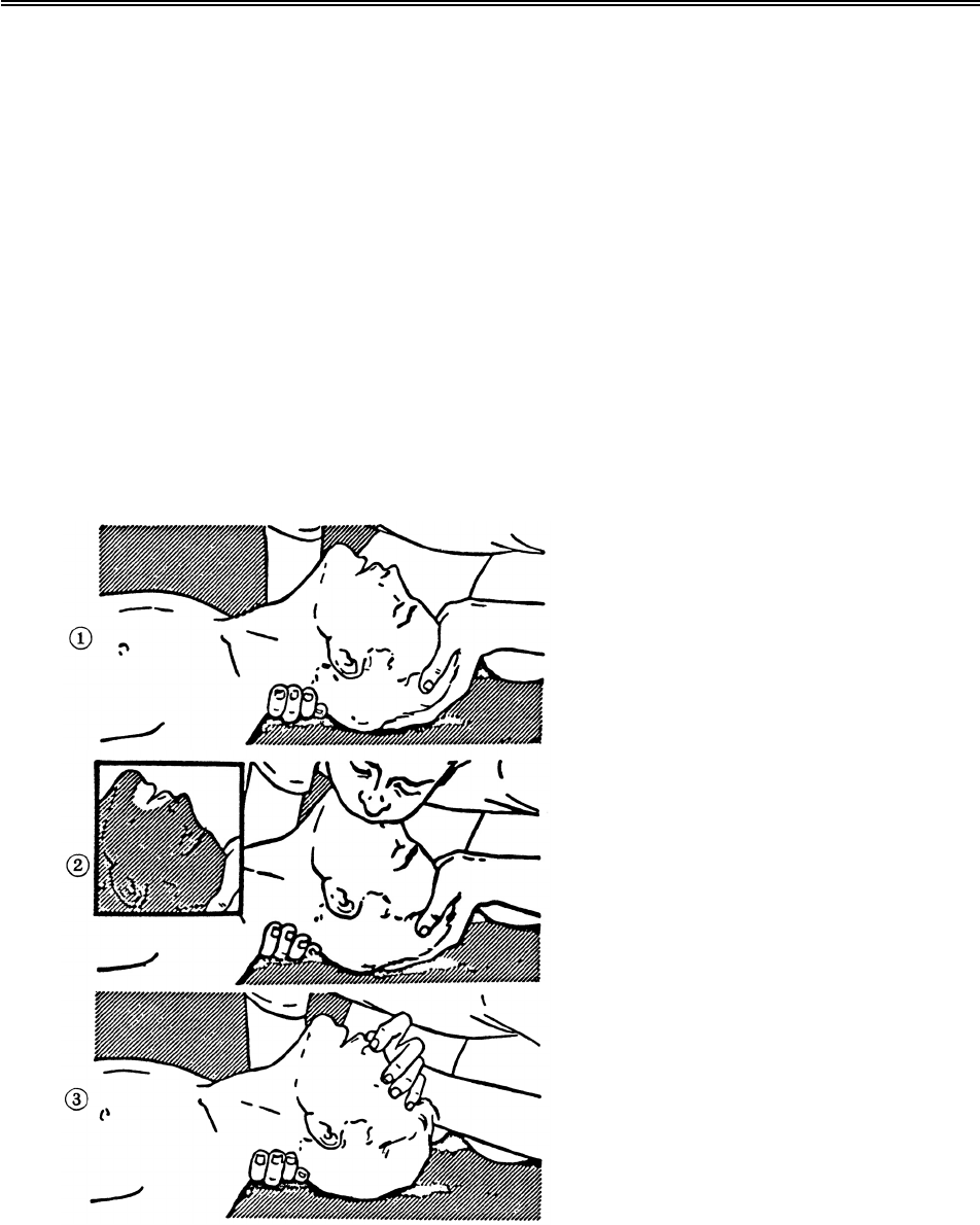
☆When pulse is beating but breathing has stopped
(Mouth-to-mouth respiration) Fig. 1
(1) Tilt the victim’s head back as far as this face looks back. (A pillow may be inserted his neck.)
(2) Push his jaw upward to open his throat wide (to spread his airway).
(3) Pinch the victim’s nostrils and take a deep breath, block his mouth completely with yours
and blow into his mouth strongly. Take a deep breath again and blow into his mouth.
Continue this 10 to 15 times a minutes (blocking his nostrils).
(4) Carefully watch that he has recovered his natural breathing and atop practicing artificial
respiration.
(5) If it is difficult to open the victim’s mouth, insert a rubber or vinyl tube into one of his
nostrils and blow into it blocking the other nostril and his mouth completely.
(6) When the victim recovers consciousness, he may try to stand up suddenly, but let him lie
calmly and serve him with a cup of hot coffee or tea and keep him warm and quiet. (Never
give him alcoholic drinks.)
Method of mouth-to-mouth respiration by raising head
(1) Raise the victim’s head. Support his
forehead with one of your hand and his
neck with the other hand. ®j
When you tilt his head backward, the
victim, in most cases, opens his mouth to
the air. This makes mouth-to mouth
respiration easy.
(2) Cover his mouth as widely as possible with
yours and press your cheek against his nose
®k
or, pinch his nostrils with your fingers to
prevent air from leaking. ®l
(3) Blow into his lungs. Continue blowing
into his mouth until his breast swells.
Blow into his mouth as quickly as possible
for the first 10 times.
Fig. 1 Mouth-to mouth respiration
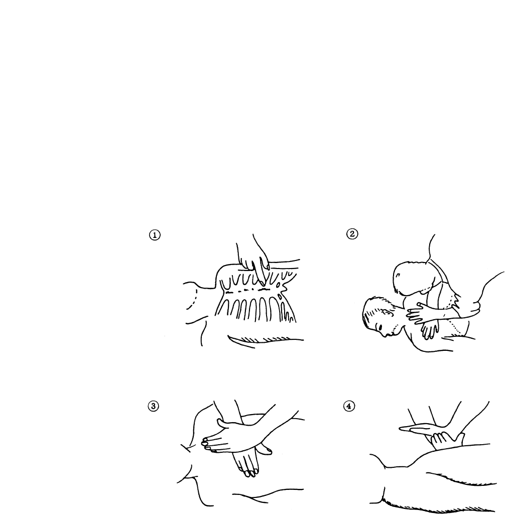
☆When both pulse and breathing have stopped
Perform the (Cardiac massage) Fig. 2 and (Mouth-to-mouth respiration) Fig. 1
When no pulse has come not to be felt, his pupils are open and no heartbeat is heard, cardiac arrest
is supposed to have occurred and artificial respiration must be performed.
(1) Place your both hands, one hand on the other, on the lower one third area of his breastbone
and compress his breast with your elbows applying your weight on his breast so that it is
dented about 2cm (Repeat compressing his breast 50 times or so a minutes). (Cardiac
massage)
(2) In case of one rescuer,
Repeat cardiac massages about 15 times and blow into his mouth 2 times quickly, and repeat
this combination.
In case of two rescuers,
One person repeats cardiac massages 15 times while the other person blow into his mouth
twice, and they shall repeat this combination. (Perform the cardiac massage and
mouth-to-mouth respiration)
(3) Examine his pupils and his pulse sometimes. When the both have returned to normal, stop
the artificial respiration, serve him with a cup of hot coffee or tea and keep him warm and
calm while watching him carefully. Commit the victim to a medical specialist depending
on his condition. (Never give him alcoholic drinks.) To let him recover from the mental
shock, it is necessary for persons concerned to understand his situations and the necessary
treatment.
Fig. 2 Cardiac massage
- i -
PREFACE
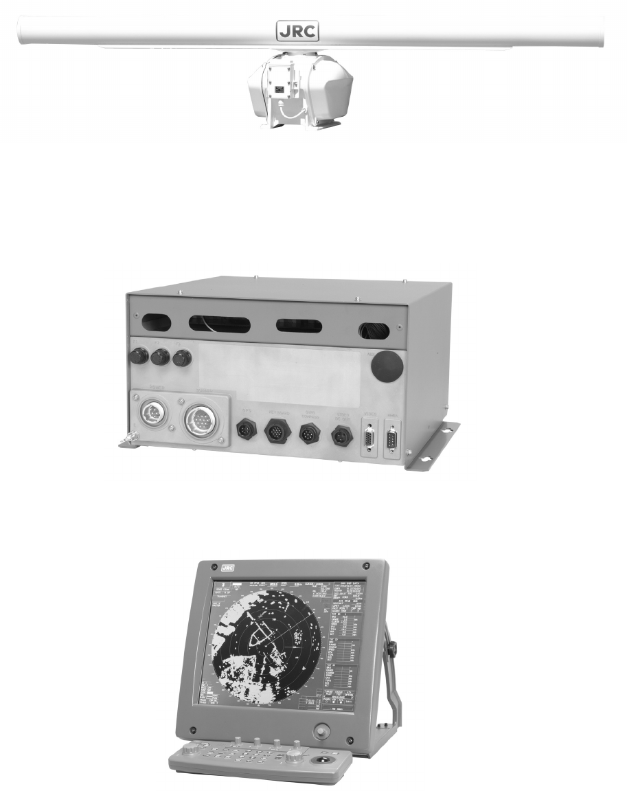
Thank you very much for purchasing the JRC marine radar equipment, JMA-5300 series.
This equipment is a marine radar equipment designed to obtain safe operation of marine ships.
This equipment consists of a radar signal transmitter-receiver unit, a LCD display unit and a scanner unit as its
main units.
● Before operating the equipment, be sure to read this instruction manual carefully for correct operation.
● Maintain this instruction manual so that operators can refer to it at anytime.
Refer to this manual when any inconvenience or defect occurs.
- ii -
●Before Operation●
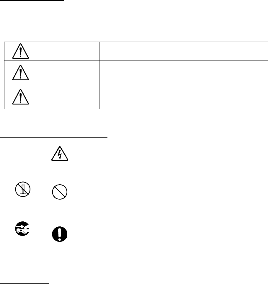
Pictorial Indication
Various pictorial indications are included in this manual and are shown on these equipment so that you can
operate them safety and correctly and prevent any danger to you and/or to other persons and any damage to
your property during operation. Such indications and their meanings are as follows.
Please understand them before you read this manual:
DANGER This indication is shown where incorrect equipment operation due to
negligence may cause death or serious injuries.
WARNING This indication is shown where any person is supposed to be in
danger of being killed or seriously injured if this indication is
neglected and these equipment are not operated correctly.
CAUTION This indication is shown where any person is supposed to be injured
or any property damage is supposed to occur if this indication is
neglected and these equipment are not operated correctly.
Examples of Pictorial Indication
Electric Shock
The r mark represents CAUTION (including DANGER and WARNING).
Detailed contents of CAUTION (“Electric Shock” in the example on the
left.) is shown in the mark.
Disassembling
Prohibited
Prohibited
The X mark represents prohibition.
Detailed contents of the prohibited action (“Disassembling Prohibited” in the
example on the left.) is shown in the mark.
Disconnect
the power
plug
Instruction
The mark represents instruction.
Detailed contents of the instruction (“Disconnect the power plug “ in the
example on the left.) is shown in the mark.
Warning Label
There is a warning label on the top cover of the equipment.
Do not try to remove, break or modify the label.
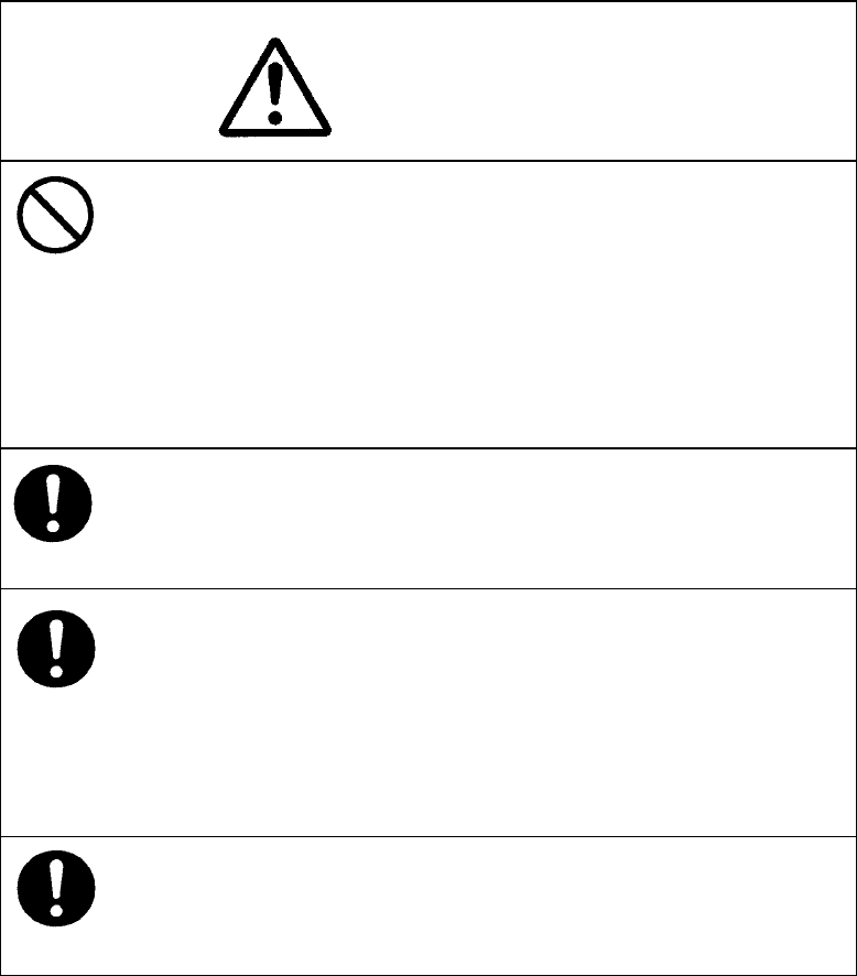
- iii -
Never conduct inspection or repair work of equipment
components.
Inspection or repair work by uncertified personnel may
result in fire hazard or electrocution.
For inspection and repair work of equipment
components, consult with our branch office, branch
shop, sales office, or our distributor in your district.
When conducting maintenance, make sure to turn the
main power off.
Failure to comply may result in electrocution.
Turn off the main power before cleaning the equipment.
Especially when a rectifier is used, make sure to turn it
off since voltage is still outputted from the rectifier even
after the indicator and the radar are turned off. Failure to
comply may result in equipment failure, or death or
serious injury due to electric shock.
When conducting maintenance work on the antenna,
make sure to turn its main power off.
Failure to comply may result in electrocution or injuries.
●PRECAUTIONS●
DANGER
- iv -
DANGER
Make sure to turn off the antenna operation switch.
Failure to comply may result in injuries caused by
physical contact with the rotating antenna.
WARNING
Never directly touch the internal components of the
antenna, receiver/transceiver, or indicator. Direct
contact with these high-voltage components may cause
electrocution. For maintenance, inspection, or
adjustment of equipment components, consult with our
branch office, branch shop, sales office, or our distributo
r
in your district.
To contact our sales department, branch offices, branch
shops, and sales offices:
Please refer to the "Office List" at the end of the
document.
Do not get close to the radiant section of the antenna. It
is a rotating part, and it may cause injuries if it suddenly
starts rotating and consequently hits the body. It is
recommended that the radiant section be installed at a
high place such as on the roof of the wheelhouse, on the
flying bridge, on the trestle, or on the radar mast so that
no one can get close to it. When any work must be done
on the antenna, make sure to turn the antenna switch off.
- v -
WARNING
About radiation from the antenna:
Never stare at the antenna from a distance closer than
that specified below for each type of antenna when it is
emitting radiation. Being within the specified distance
from the center of the front face of the antenna may
cause radiation exposure which could result in injuries
(especially of the eyes).
NKE-2102/2252 (radiodensity: 10 W/m2): 0.6 m
NKE-1075 (radiodensity: 10 W/m2): 1.1 m
NKE-1075 (radiodensity: 100 W/m2): 25 cm
Make sure to install the antenna at a place higher than
human height.
Direct exposure to electromagnetic waves at close range
will have adverse effects on the human body.
Direct exposure to electromagnetic waves at close range
will have adverse effects on the human body. When it is
necessary to get close to the antenna for maintenance or
inspection purposes, make sure to turn the indicator
power switch to "OFF" or "STBY."
Direct exposure to electromagnetic waves at close range
will have adverse effects on the human body.
When conducting maintenance work, make sure to turn
off the power and unplug the power connector J1 of the
processor so that the power supply to the equipment is
completely cut off.
Some equipment components can carry electrical current
even after the power switch is turned off, and conducting
maintenance work without unplugging the power
connector may result in electrocution, equipment failure,
or accidents.
- vi -
CAUTION
Use the radar only as a navigation aid. The final
navigation decision must always be made by the operator
him/herself. Making the final navigation decision based
only on the radar display may cause accidents such as
collisions or running aground.
WARNING
When cleaning the display screen, do not wipe it too
strongly with a dry cloth. Also, do not use gasoline or
thinner to clean the screen. Failure to comply will result
in damage to the screen surface.
When disposing of used lithium batteries, be sure to
insulate the batteries by attaching a piece of adhesive
tape on the Å and ¡ terminals. Failure to comply may
cause heat generation, explosion, or fire when the
batteries get shorted out.
Do not change MBS Level/Area unless absolutely
necessary.
Incorrect adjustment will result in deletion of nearby
target images and thus collisions may occur resulting in
death or serious injuries.
- vii -
CAUTION
Use ATA only as a navigation aid. The final navigation
decision must always be made by the operator
him/herself. Making the final navigation decision based
only on ATA information may cause accidents.
ARPA information such as vector, target numerical data,
and alarms may contain some errors. Also, targets that
are not detected by the radar cannot be acquired or
tracked.
Making the final navigation decision based only on the
radar display may cause accidents such as collisions or
running aground.
When using the [AUTO SEA] function, never set the
suppression level too high canceling out all image noises
from the sea surface at close range.
Detection of not only echoes from waves but also targets
such as other ships or dangerous objects will become
inhibited.
When using the [AUTO SEA] function, make sure to
choose the most appropriate image noise suppression
level.
When using the [AUTO RAIN] function, never set the
suppression level too high canceling out all image noises
from the rain or snow at close range.
Detection of not only echoes from the rain or snow but
also targets such as other ships or dangerous objects will
become inhibited.
When using the [AUTO RAIN] function, make sure to
choose the most appropriate image noise suppression
level.
A malfunction may occur if the power in the ship is
instantaneously interrupted during operation of the
radar. In this case, the power should be turned on
again.
- viii -
CAUTION
When setting a guard zone, make sure to properly adjust
gain, sea-surface reflection suppression level, and
rain/snow reflection suppression level so that the optimal
target images are always on the radar screen. The guard
zone alarm will not be activated for targets undetected by
the radar, and it may result in accidents such as
collisions.
The simulation function is used exclusively for deciding
whether or not ATA/ARPA is properly operating.
Therefore, never use this function unless you wish to
check ATA/ARPA operations.
Note especially that, if this function is used during actual
navigation, simulated targets are displayed and may
become confused with other actual targets. Therefore,
never use this function during actual navigation.
Optimal values have been set for VD LEVEL and
CONSTANT; therefore, never change their values unless
absolutely necessary. Failure to comply may result in
accidents that would lower ARPA performance.
Make sure to shut off the main power before replacing
parts. Failure to comply may result in electrocution or
equipment failure.
When replacing magnetrons, make sure to shut off the
main power and let the equipment stand for more than 5
minutes to discharge the high-voltage circuit. Failure to
comply may result in electrocution.
- ix -
CAUTION
Make sure to take off your watch when your hand must
get close to the magnetron.
Failure to comply may result in damage to the watch
since the magnetron is a strong magnet.
Make sure that two or more staff member work together
when replacing the LCD. If only one person attempts to
replace the LCD, he/she may drop it and become injured.
Do not directly touch the inverter circuit of the LCD
display with a bare hand since high voltage temporarily
remains in the circuit even after the main power is shut
off.
Failure to comply may result in electrocution.
Any adjustments must be made by specialized service
personnel.
Incorrect settings may result in unstable operation.
Do not make any adjustments during navigation. Failure
to comply may result in adverse effects on the radar
function which may lead to accidents or equipment
failure.
Any adjustments must be made by specialized service
personnel.
Failure to comply may result in accidents or equipment
failure.
Do not make any adjustments during navigation. Failure
to comply may result in adverse effects on the radar
function which may lead to accidents or equipment
failure.
- x -
CAUTION
Do not change the quantization level settings unless
absolutely necessary. If set at an inappropriate value,
the acquisition or tracking function of ARPA deteriorates,
and this may lead to accidents.
- xi -
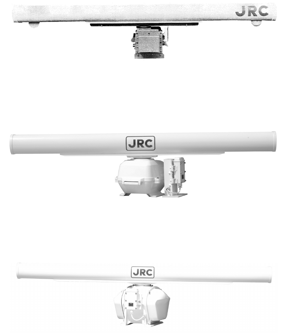
EQUIPMENT APPEARANCE
Scanner Unit Type NKE-1075 (12 feet)
Scanner Unit Type NKE-2102-6 (6 feet)
Scanner Unit Type NKE-2252-7 (7 feet)
- xii -
Scanner Unit Type NKE-2252-9 (9 feet)
NDC-1273 Processor Unit (Desktop Type)
NWZ-147 Display Unit (Desktop Type)
NCE-7699 Operation Unit (Desktop Type)
NCD-4510 Display Unit (Desktop Type)

- xiii -
CONTENTS
PREFACE................................................................................................................i
BEFORE OPERATION ........................................................................................... ii
PRECAUTIONS..................................................................................................... iii
EQUIPMENT APPEARANCE ................................................................................ xi
GLOSSARY.......................................................................................................... xx
1. GENERAL AND EQUIPMENT COMPOSITION
1.1 FUNCTIONS........................................................................................... 1-1
1.1.1 FUNCTION OF THIS SYSTEM ........................................................ 1-1
1.2 FEATURES............................................................................................. 1-2
1.3 CONFIGURATION.................................................................................. 1-4
1.4 EXTERIOR DRAWINGS......................................................................... 1-5
1.5 GENERAL SYSTEM DIAGRAMS......................................................... 1-14
2. NAMES AND FUNCTIONS OF CONTROL PANEL KEYS
AND FUNCTIONS OF SOFTWARE BUTTONS
2.1 NAMES AND FUNCTIONS OF CONTROL PANEL KEYS...................... 2-1
2.2 FUNCTIONS OF SOFTWARE BUTTONS.............................................. 2-7
3. BASIC OPERATION
3.1 FLOW OPERATION................................................................................ 3-1
3.1.1 POWER ON AND START THE SYSTEM ......................................... 3-2
3.1.2 OBSERVE AND ADJUST VIDEO ..................................................... 3-3
3.1.3 ACQUIRE AND MEASURE DATA .................................................... 3-3
3.1.4 END THE OPERATION AND STOP THE SYSTEM ......................... 3-4
3.2 MENU COMPOSITION........................................................................... 3-5
3.2.1 OVERVIEW OF MENU STRUCTURE.............................................. 3-5
3.2.2 BASIC MENU OPERATION ............................................................. 3-6
3.3 PREPARATION ................................................................................ 3-8
- xiv -
3.3.1 ADJUST DISPLAY BRILLIANCE.......................................................3-8
3.3.2 ADJUST CONTRAST........................................................................3-8
3.3.3 ADJUST OPERATION PANEL BRILLIANCE [PANEL]......................3-9
3.3.4 SWITCH DAY/NIGHT MODE [DAY/NIGHT]......................................3-9
3.3.5 ADJUST BRILLIANCE OF INFORMATION ON RADAR DISPLAY
(BRILLIANCE SETTING) ................................................................3-10
3.3.6 ADJUST SOUND VOLUME (BUZZER VOLUME) .......................... 3-11
3.3.7 RESET ALARM BUZZER [ALARM ACK] ........................................ 3-11
3.3.8 SET DISPLAY COLOR....................................................................3-12
3.4 BASIC OPERATIONS ...........................................................................3-15
3.4.1 START TRANSMISSION [TX/PRF].................................................3-15
3.4.2 STOP TRANSMISSION [STBY] ......................................................3-15
3.4.3 CHANGE RANGE (OBSERVATION RANGE SCALE)
[RANGE+/-] .....................................................................................3-15
3.4.4 TUNE ..............................................................................................3-16
3.4.5 CONTROL SENSITIVITY [GAIN/PL]...............................................3-16
3.4.6 SUPPRESS SEA CLUTTER [AUTO-SEA]......................................3-17
3.4.7 SUPPRESS RAIN/SNOW CLUTTER [AUTO-RAIN].......................3-19
3.4.8 REJECT RADAR INTERFERENCE [IR] .........................................3-21
3.4.9 HIDE/DISPLAY RANGE RINGS (RINGS).......................................3-22
3.4.10 HIDE SHIP’S HEADING LINE (HL OFF).........................................3-22
3.4.11 HIDE GRAPHICS INFORMATION ON RADAR DISPLAY
(GRAPHIC DISPLAY)......................................................................3-23
3.5 GENERAL OPERATIONS .....................................................................3-24
3.5.1 MOVE CROSS CURSOR MARK BY TRACKBALL.........................3-24
3.5.2 USE EBLS (ELECTRONIC BEARING LINES) [EBL1/2] .................3-25
3.5.3 SET EBL OPERATION (EBL1 /2 SETTING) ...................................3-27
3.5.4 DISPLAY VARIABLE RANGE MARKERS [VRM1/VRM2]...............3-30
3.5.5 DISPLAY PARALLEL INDEX LINES (PARALLEL INDEX LINE) .....3-33
3.5.6 SWITCH BEARING DISPLAY MODE [AZI MODE] .........................3-41
3.5.7 SWITCH TRUE/RELATIVE MOTION DISPLAY MODE [TM/RM]....3-42
3.5.8 MOVE OWN SHIP’S DISPLAY POSITION [OFF CENT].................3-43
3.5.9 DISPLAY OTHER SHIPS’ TRAILS [TRAILS] ..................................3-44
3.5.10 SWITCH PULSE LENGTH (GAIN/PL) ............................................3-47
3.5.11 EXPAND TARGETS (TARGET ENHANCE) ....................................3-48
3.5.12 USE VIDEO PROCESS (PROCESS) .............................................3-49
3.5.13 ZOOM .............................................................................................3-50
3.5.14 USE MARKER [MOB] .....................................................................3-51
3.5.15 MARKING [MARK] ..........................................................................3-52
3.5.16 OPERATE EBL MANEUVER FUNCTION (EBL MANEUVER)........3-53

- xv -
3.5.17 OPERATE MULTI-FUNCTION CONTROL [MULTI]........................ 3-56
3.5.18 OPERATE USER KEY SWITCHES [USER KEY 1/2]..................... 3-58
3.5.19 OPERATION OF GUARD ZONE [ATA GUARD ZONE].................. 3-60
3.5.20 RADAR ALARM (RADAR ALARM)................................................. 3-63
3.6 DISPLAY OWN SHIP’S TRACK............................................................ 3-67
3.6.1 DISPLAY OWN SHIP’S TRACK (DISPLAY OWN TRACK) ............ 3-67
3.6.2 SET OWN SHIP’S TRACK DATA STORAGE INTERVAL
(OWN TRACK INTERVAL) ............................................................. 3-68
3.6.3 CLEAR OWN SHIP’S TRACK DATA (CLEAR OWN TRACK) ........ 3-69
3.6.4 CANCEL STORING OF OWN SHIP’S TRACK DATA
(OWN TRACK MEMORY) .............................................................. 3-70
3.7 DISPLAY CHARTS ............................................................................... 3-71
3.7.1 DISPLAY COASTLINE ROM CARD PRODUCED BY JRC............ 3-71
3.7.2 DISPLAY ERC CARD ..................................................................... 3-72
3.7.3 FILL CHARTS (FILL LAND AREA) ................................................. 3-73
3.8 DISPLAY NAVIGATION INFORMATION............................................... 3-74
3.8.1 DISPLAY WAYPOINT MARKS (WAYPOINT DISPLAY).................. 3-74
3.8.2 DISPLAY NAVIGATION INFORMATION
(NAV DISPLAY SETTING).............................................................. 3-75
3.8.3 CREATE/EDIT NAVIGATION INFORMATION
(EDIT USER MAP) ......................................................................... 3-76
3.8.4 SET NAVIGATION INFORMATION (USER MAP SETTING).......... 3-82
3.8.5 SET AND DISPLAY GEODETIC SYSTEM ..................................... 3-89
3.9 OPERATE PERFORMANCE MONITOR (PM DISPLAY)...................... 3-91
3.9.1 OPERATION PROCEDURES ........................................................ 3-91
3.10 APPLIED OPERATIONS ...................................................................... 3-97
3.10.1 SET RADAR SIGNAL PROCESSING (PROCESS SETTING) ....... 3-97
3.10.2 SET RADAR TRAILS (RADAR TRAILS SETTING)...................... 3-100
3.10.3 SET CURSOR (CURSOR SETTING)........................................... 3-102
3.10.4 SET SCREEN............................................................................... 3-103
3.10.5 SET SCANNER (TRX SETTING) ................................................. 3-107
3.10.6 SET CHART DISPLAY (MAP SETTING) ...................................... 3-109
3.10.7 SET LORAN C (LORAN C CORRECTION) ..................................3-119
3.11 USE FUNCTION SWITCH [FUNC]..................................................... 3-120
3.11.1 OPERATION PROCEDURES ...................................................... 3-120
3.11.2 FUNCTION SETTING MENU ITEMS ........................................... 3-121
3.11.3 OVERVIEW OF FUNCTION OPERATIONS................................. 3-122
3.11.4 OVERVIEW OF STORED FUNCTION SETTING DATA............... 3-125
3.11.5 PERSONAL INFORMATION (PIN SETTING)............................... 3-126
3.12 USING CARD ..................................................................................... 3-129
- xvi -
3.12.1 SAVE IN AND TRANSFER TO CARD (MEM CAPA/COPY) .........3-129
3.12.2 ERASE/INITIALIZE CARD MEMORY (CLR MEM INIT CARD).....3-133
4. MEASUREMENT OF RANGE AND BEARING
4.1 MEASUREMENT BY TRACKBALL .........................................................4-1
4.2 MEASUREMENT BY RANGE RINGS.....................................................4-2
4.3 MEASUREMENT BY EBLS AND VRMS .................................................4-3
4.4 MEASUREMENT BETWEEN TWO OPTIONAL POINTS .......................4-5
5. HOW TO USE ATA/ARPA
5.1 PREPARATION .......................................................................................5-2
5.1.1 COLLISION AVOIDANCE .................................................................5-4
5.1.2 DEFINITIONS OF SYMBOLS ...........................................................5-7
5.1.3 SETTING COLLISION DECISION CRITERIA (CPA/TCPA LIMIT) ....5-9
5.1.4 SETTING VECTORS (VECTOR TIME)...........................................5-10
5.1.5 SETTING CPA RING (CPA RING)................................................... 5-11
5.1.6 SETTING AUTOMATIC ACQUISITION KEY ASSIGNMENT
(GZ ALARM KEY SETTING)...........................................................5-12
5.2 EPA OPERATION..................................................................................5-13
5.2.1 PLOTTING TARGETS.....................................................................5-13
5.2.2 MODIFYING PLOTTED TARGET DATA .........................................5-14
5.2.3 CANCELING PLOTTED TARGET DATA.........................................5-14
5.2.4 DISPLAYING NUMERIC DATA OF PLOTTED TARGETS ..............5-15
5.2.5 SETTING EPA ALARM (AUDIBLE WARNING)...............................5-16
5.3 ATA/ARPA OPERATION........................................................................5-17
5.3.1 ACQUIRING TARGET.....................................................................5-17
5.3.2 CANCELING UNWANTED TARGETS ............................................5-19
5.3.3 DISPLAYING TARGET ID NO. (TARGET NUMBER DISPLAY) ......5-20
5.3.4 ATA/ARPA DATA DISPLAY..............................................................5-21
5.3.5 TARGET DATA DISPLAY ................................................................5-26
5.3.6 ALARM DISPLAY............................................................................5-30
5.3.7 TRIAL MANEUVERING (TRIAL).....................................................5-34
5.3.8 ATA/ARPA SIMULATION.................................................................5-38
5.3.9 SETTING ATA/ARPA TRACKS (ATA TRACK SETTING) ................5-44
5.4 AIS OPERATION...................................................................................5-51
5.4.1 INITIAL SETTING............................................................................5-52
5.4.2 SETTING AIS DISPLAY FUNCTION (AIS FUNCTION) ..................5-54

- xvii -
5.4.3 ACTIVATING AIS TARGETS .......................................................... 5-55
5.4.4 DEACTIVATING AIS TARGETS ..................................................... 5-56
5.4.5 SETTING AIS SYMBOL DISPLAY FUNCTION
(AIS SYMBOL DISPLAY)................................................................ 5-57
5.4.6 DISPLAYING NUMERIC DATA OF AIS TARGETS......................... 5-58
5.4.7 SETTING ATA/ARPA SYMBOL DISPLAY FUNCTION
(ATA SYMBOL DISPLAY) ............................................................... 5-60
5.4.8 SETTING AIS FILTER (AIS FILTER SETTING).............................. 5-61
5.4.9 DECIDING AIS TARGET AND ARPA TARGET AS THE
SAME ONE (IDENTICAL DISTANCE)............................................ 5-64
5.4.10 CONDITIONS FOR DECIDING AIS TARGET TO BE LOST .......... 5-66
5.4.11 DISPLAYING AIS SYMBOLS ......................................................... 5-67
5.4.12 AIS ALARM DISPLAY..................................................................... 5-68
5.4.13 RESTRICTIONS............................................................................. 5-69
6. TRUE AND FALSE ECHOES ON DISPLAY
6.1 RADAR WAVE WITH THE HORIZON .................................................... 6-2
6.2 STRENGTH OF REFLECTION FROM THE TARGET............................ 6-4
6.3 SEA CLUTTERS..................................................................................... 6-5
6.4 FALSE ECHOES .................................................................................... 6-6
6.5 DISPLAY OF RADAR TRANSPONDER (SART) .................................... 6-9
7. MAINTEMANCE
7.1 ROUTINE MAINTENANCE..................................................................... 7-1
7.2 MAINTENANCE ON EACH UNIT ........................................................... 7-2
8. TROUBLE SHOOTING AND ADJUSTMENT
8.1 PERFORMANCE CHECK ...................................................................... 8-1
8.2 FAULT FINDING ................................................................................... 8-21
8.3 TROUBLE SHOOTING......................................................................... 8-22
8.4 REPLACEMENT OF MAJOR PARTS................................................... 8-27
8.5 ADJUSTMENTS ................................................................................... 8-30
8.6 SETTING .............................................................................................. 8-62
9. AFTER-SALES SERVICE
- xviii -
10. DISPOSAL
10.1 DISPOSAL OF THE UNIT .....................................................................10-1
10.2 DISPOSAL OF USED BATTERIES .......................................................10-2
10.3 DISPOSAL OF USED MAGNETRON ...................................................10-3
11. SPECIFICATIONS
11.1 JMA-5310-6 TYPE RADAR................................................................... 11-1
11.2 JMA-5320-7/9 TYPE RADAR ................................................................ 11-2
11.3 JMA-5330-12 TYPE RADAR................................................................. 11-3
11.4 SCANNER (NKE-2102)......................................................................... 11-4
11.5 SCANNER (NKE-2252-7/9)................................................................... 11-5
11.6 SCANNER (NKE-1075)......................................................................... 11-6
11.7 SCANNER (NKE-2252-6HS)................................................................. 11-7
11.8 DISPLAY UNIT(NCD-4510)................................................................... 11-8
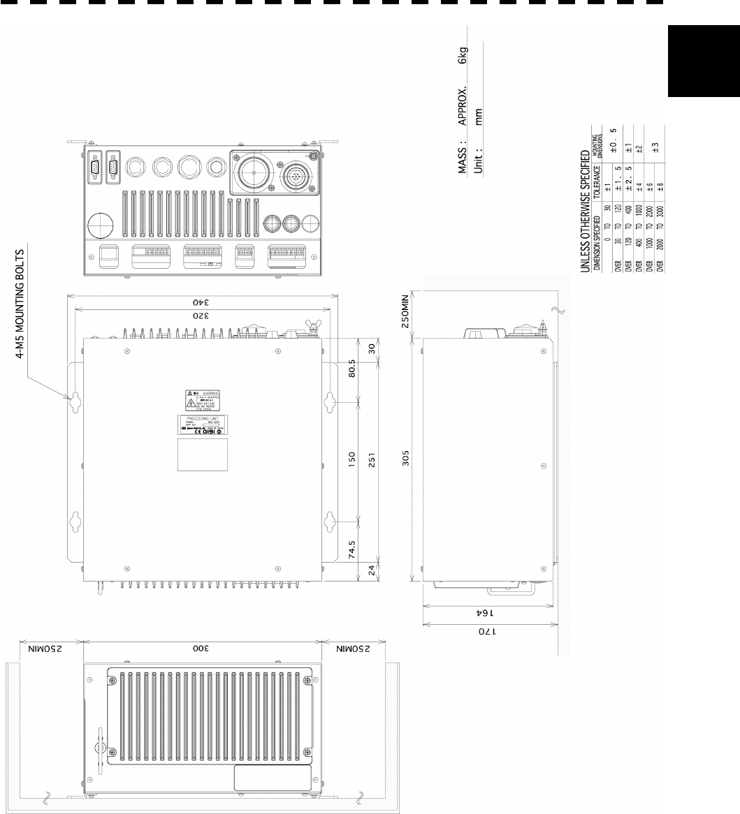
11.9 PROCESSOR UNIT(NDC-1273)........................................................... 11-9
11.10 PLOTTER UNIT .................................................................................. 11-11
11.11 ARPA-1 (HIGH PERFORMANCE ARPA) ............................................ 11-13
11.12 ARPA-2 (NORMAL EDITION ATA) ...................................................... 11-14
11.13 KEYBOARD UNIT ............................................................................... 11-15
11.14 INPUT ENABLE SIGNAL .................................................................... 11-16
11.15 OUTPUT ENABLE SIGNAL ................................................................ 11-17
11.16 STANDARD CONFIGURATION .......................................................... 11-18
11.17 EQUIPMENT DISTANCE BETWEEN INSTRUMENTS....................... 11-19
11.18 OTHERS (OPTION) ............................................................................ 11-20
APPENDIX
OPERATION MANUAL OF INTERSWITCH(NQA-3141-4)
ATTACHED DRAWING 1 CIRCUIT DIAGRAM OF RADAR, TYPE
JMA-5310-6/5320-7/9
ATTACHED DRAWING 2 CIRCUIT DIAGRAM OF RADAR, TYPE JMA-5330-12
ATTACHED DRAWING 3 INTER CONNECTION DIAGRAMS OF RADAR, TYPE
JMA-5310-6
ATTACHED DRAWING 4 INTER-BOARD CONNECTION DIAGRAM OF RADAR,
TYPE JMA-5320-7/9
ATTACHED DRAWING 5 INTER-BOARD CONNECTION DIAGRAM OF RADAR,
TYPE JMA5330-12
ATTACHED DRAWING 6 POWER SYSTEM DIAGRAM OF RADAR, TYPE

- xix -
JMA-5310-6
ATTACHED DRAWING 7 POWER SYSTEM DIAGRAM OF RADAR, TYPE
JMA-5330-12
ATTACHED DRAWING 8 INTERNAL CONNECTION DIAGRAM OF DISPLAY
UNIT, TYPE NCD-4510
ATTACHED DRAWING 9 INTERNAL CONNECTION DIAGRAM OF PROCESSOR
UNIT, TYPE NCD-1273
ATTACHED DRAWING 10 INTERNAL CONNECTION DIAGRAM OF OPERATION
UNIT, TYPE NCE-7699
ATTACHED DRAWING 11 INTERNAL CONNECTION DIAGRAM OF
CONNECTION UNIT, TYPE NQE-3151
ATTACHED DRAWING 11 RADAR DISPLAY
ATTACHED DRAWING 12 OVER VIEW OF RADAR MENU

- xx -
GLOSSARY
This section describes the main terms used for this equipment and general related maritime terms.
ARPA:
Automatic Radar Plotting Aid.
AZI MODE (Azimuth Stabilization MODE):
Bearing display mode
Anti-clutter rain (FTC):
Rain/snow clutter suppression
Anti-clutter sea (STC):
Sea clutter suppression
ATA:
Automatic Tracking Aid
BCR:
Bow Crossing Range
BCT:
Bow Crossing Time
BRG:
Bearing
CPA (Closest Point of Approach):
The closest point of approach from own ship,
which can be set by the observer.
COG (Course Over Ground):
Course relative to the ground.
CUP (Course-Up):
Own ship’s course is pointed to the top
center of the radar display.
DRIFT:
The current velocity for manual correction
or the current speed on the horizontal axis of
the 2-axis log is displayed.
EBL (Electronic Bearing Line):
An electronic bearing line originated from
own ship’s position.
ENH (Enhance):
A target can be enlarged.
Floating EBL (Floating Electronic Bearing
Line):
Floating electronic bearing line originated
from an arbitrary point.
GND:
Stabilization relative to the ground.
GPS (Global Positioning System):
The position of a GPS receiver can be
determined by the signals from GPS
satellites.
Guard Zone:
Alarm ring against intrusion
HDG (Heading):
Own ship’s heading bearing.
The display ranges from 000 to 360 degrees
as scanned clockwise.
HL (Heading Line):
Ship’s heading line
HUP (Head-Up):
Own ship’s heading line is always pointed to
the top center of the radar display.
IMO:
International Maritime Organization
Interswitch:
A device to switch over two or more radar
display units and two or more antennas.
IR (Interference Rejector):
Radar interference rejector
MRK (Mark):
Reflection plot
NM (Nautical Mile):
1NM=1852m
NSK (North Stabilization Kit):
True bearing unit
NUP (North-Up):
The north is always pointed to the top center
of the radar display.
OWN TRACK:
Display function of own ship’s track
PI (Parallel Index Line):
Parallel index line
PIN (Personal Access Code):
Information set by the user (personal code)
PM (Performance Monitor):
An additional unit to monitor the transmitted
power and the receiving sensitivity of radar
equipment.
PROC (Process):
Target processing function
PPI:
Plan Position Indicator
Relative Vector:
A target’s movement predicted relative to
own ship.
RR (Range Rings):
Fixed range ring
RM (Relative Motion):
Relative motion presentation
Own ship’s position is fixed and other
targets move relative to own ship.
S/X Band:
Radio frequency bands
S: 3GHz band, X: 9 GHz band

- xxi -
SCANNER:
Antenna
SEA:
Sea clutter suppression
SET:
The current direction for manual correction
or the current speed on the horizontal axis of
the 2-axis log is displayed.
SOG (Speed Over Ground):
Speed relative to the ground.
STAB (Stabilization):
Stabilization
TCPA (Time to Closest Point of Approach):
The time to approach the closest point from
own ship.
TM (True Motion):
True motion presentation
A presentation in which own ship and any
other target move depending on their
individual movements.
TRAILS:
Function of displaying tracks of other ships.
TRIAL:
Trial maneuvering
True Vector:
A target’s true movement predicted as the
result of entering own ship’s direction and
speed.
VRM:
Variable Range Marker
WATER:
Stabilization relative to the water

xxii
3
4
5
2
1
6
7
8
9
10
11
APPENDIX
APPENDIX
1 GENERAL AND EQUIPMENT COMPOSITION
2 NAME AND FUNCTION OF CONTROL PANEL KEYS
AND FUNCTION OF SOFTWARE BUTTONS
3 BASIC OPERATION
4 MEASUREMENT OF RANGE AND BEARING
5 OPERATION OF ARPA AND AIS
6 TRUE AND FALSE ECHOES ON DISPLAY
7 MAINTENANCE
8 COUNTERMEASURES FOR TROUBLE AND
ADJUSTMENT
9 AFTER-SALES SERVICE
10 DISPOSAL
11 SPECIFICATION
APPENDIX
1 - 1
SECTION 1
GENERAL AND EQUIPMENT
COMPOSITION
1.1 Functions...................................... 1-1
1.1.1 Function of This System ...... 1-1
1.2 Features ........................................ 1-2
1.3 Configuration................................ 1-4
1.4 Exterior Drawings ........................1-5
1.5 General System Diagrams......... 1-15

1 - 1
1.1 FUNCTIONS
This equipment is a high-performance radar equipment consisting of a scanner unit, a transmitter-receiver unit
and a high resolution color LCD display unit.
1.1.1 Function of This System
The JMA-5300 series is a color radar system designed to comply with the international standards of the
IMO.
The main functions include:
· sensitivity adjustment
· sea clutter and rain/snow clutter suppression
· interference reflector
· bearing and range measurement using a cursor, fixed/variable range markers, and electronic bearing
line
· own track display
· NAV line and marker displays
· TM (True Motion) presentation
· self-diagnostic facilities
· radar performance monitoring (Performance Monitor)
· ARPA functions (manual/automatic, target acquisition and tracking, vector and trail displays and alarm
displays) (option)
· simple plotter functions (marker and line display, destination/route setting) (option)
· 4-unit switchover (Inter switch) function (option)

1 - 2
1
1.2 FEATURES
Realization of Large, Easy-to-see Screen with High Resolution
The 18.1-inch color LCD with high resolution of 1280 ´ 1024 pixels can display radar images of 250 mm or
more in diameter. Even short-range targets can also be displayed as high-resolution images.
Target Detection by Latest Signal Processing Technology
The system employs the latest digital signal processing technology to eliminate undesired clutter from the radar
video signals that are obtained from the receiver with a wide dynamic range, thus improving the target
detection.
Advanced Technology Based ARPA/ATA Functions (Option)
The ARPA target acquisition and tracking performance is enhanced by the use of the fastest DSP and tracking
algorithm. So stable operation in target tracking under clutter is ensured.
· Acquisition and tracking of 100 targets for ARPA, 30 targets for ATA.
· Hazardous conditions are represented by shapes and colors of symbols as well as sounds.
· Trial maneuvering functions provided. (ARPA)
· Trails of up to 20 target ships can be stored with a maximum of 1,500 points for each of them, and displayed
distinguished by using seven different colors.
Overlay of Radar Images, Coastlines, and Own Ship's Track
As well as operator-created NAV lines, the data of coastlines, objects such as buoys, and own ship's
tracks/ARPA trails, which is stored on the memory card can be superimpose-displayed with radar images and
radar trails in all display modes including the head-up mode.
Use of the optional plotter function enables the creation/display of marks and lines and the settings of
waypoints/courses.
Easy Operation with GUI
All the radar functions can be easily controlled by simply using the trackball and two switches to operate the
buttons shown on the radar display.

1 - 3
Improved Day/Night Mode
Two types of background colors are available in each Day/Night mode (total 4 background colors).
Each background color can be reproduced to be suited for the user’s operating environment by simple key
operation. The radar echoes and a variety of graphics can also be represented in different colors, ensuring
easy-to-see displays.
Compact Design and Low Power Consumption
Since an LCD has been implemented as the display device, the weight of the display is greatly reduced and the
power consumption is lowered in comparison with the conventional radar equipment.
Self-diagnostic Program Incorporated
The Self-diagnostic program always monitors all the functions of the system. If any function deteriorates, an
alarm message will appear on the radar display and an alarm sounds at the same time. Even when the system
is operating, the functionality test can be carried out. (except on some functions)
Performance Monitor (Option)
The radar performance (transmitted output power and receiving sensitivity) can appear on the radar display.
* The PM unit (NJU-63/64) is needed separately.
Easy Interswitch Operation (Option)
If an interswitch unit (option) is connected, up to four JMA-5300 radars can be switched over by performing
simple operation.
* An interswitch (NQA-3141-4) is needed separately.
Various Functions
· TRAILS (Other ship’s) track display
· TM (True Motion display)
· Head-up/North-up/Course-up display
· Own ship’s track display
· Guard Zone function
1 - 4
1
1.3 CONFIGURATION
Scanners and Transmitted Output Powers
SCANNER TYPE TRANSMITTED
OUTPUT POWER BAND
JMA-5310-6 6 FT SLOT ANTENNA 10 KW X
JMA-5320-7 7 FT SLOT ANTENNA 25 KW X
JMA-5320-9 9 FT SLOT ANTENNA 25 KW X
JMA-5320-6HS 6 FT SLOT ANTENNA 25 KW X
JMA-5330-12 12 FT SLOT ANTENNA 30 KW S
Radar Configuration and Ship’s Mains
RADAR
MODEL
SCANNER
UNIT PM UNIT TRANSMITTER-
RECEIVER UNIT SHIP’S MAINS
JMA-5310-6 NKE-2102-6 NJU-64 NCD-4510 24 VDC
JMA-5320-7 NKE-2252-7 NJU-64 NCD-4510 24 VDC
JMA-5320-9 NKE-2252-9 NJU-64 NCD-4510 24 VDC
JMA-5320-6HS NKE-2252-6HS NJU-64 NCD-4510 24 VDC
NCD-4510 24 VDC
100 VAC, 1f, 50/60HZ
220 VAC, 1f, 50/60HZ
JMA-5330-12 NKE-1075A NJU-63 *NQE-3151
220 VAC, 3f, 50/60HZ
* The NQE-3151 included in JMA-5330-12 is a connection unit to supply AC power for the motor to the
scanner unit.
Notes:
1. The JMA-5330-12 needs 24 VDC as the power supply of the processor, and AC power for the motor
to drive the scanner.
2. The table above shows three types of power supplies available for the motor of JMA-5330-12.
3. An optional rectifier is necessary for using Ship's Mains 100/110/115/200/220/230 VAC.
4. The display NCD-4510 has a separate structure consisting of the following:
Display unit NWZ-147
Processor NDC-1273
Operation panel NCE-7699
5. The ship with radar of IMO conformity must mount a PM unit.

1 - 5
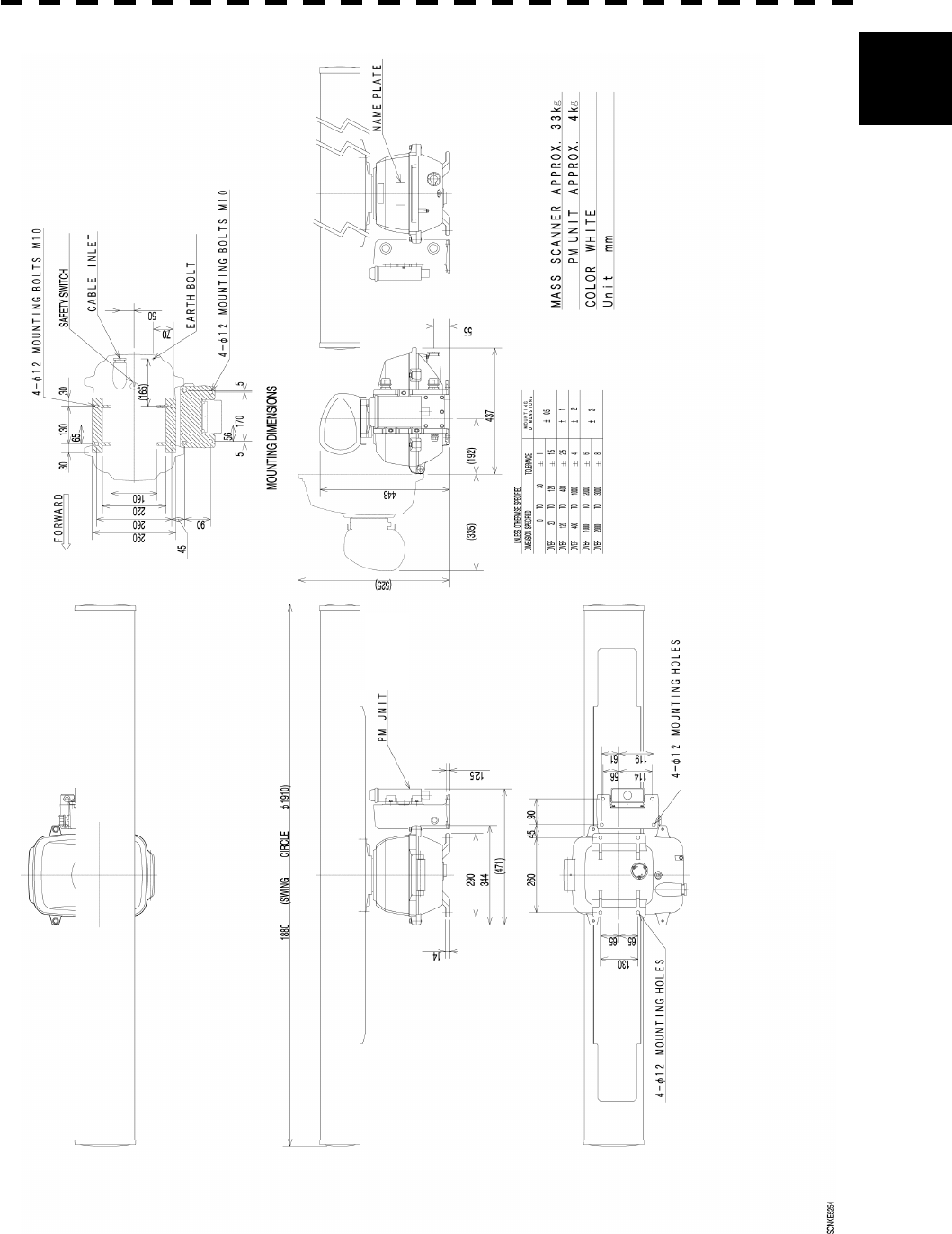
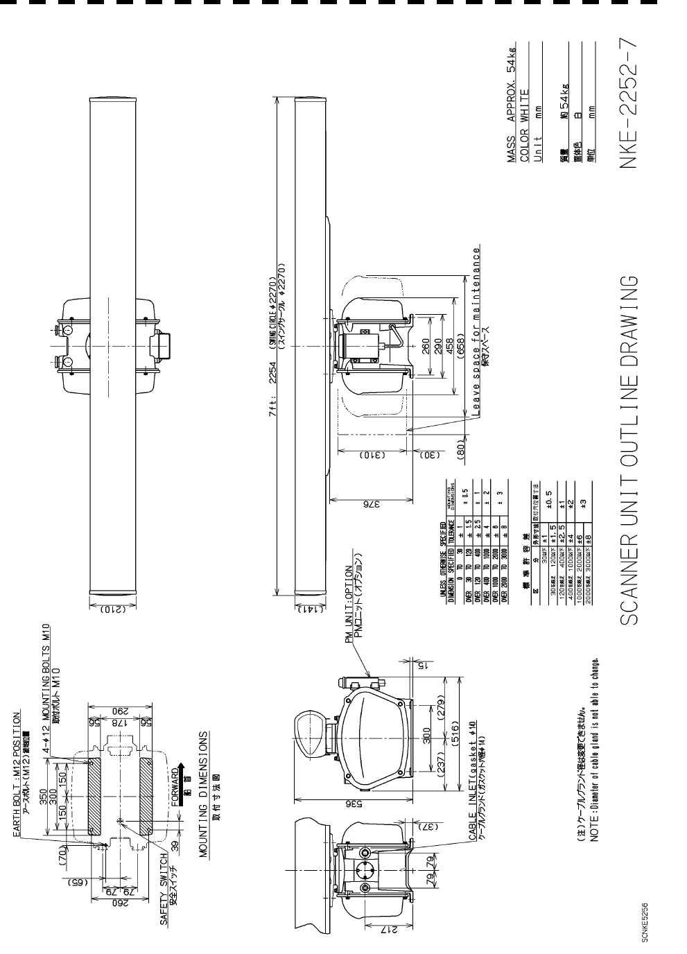
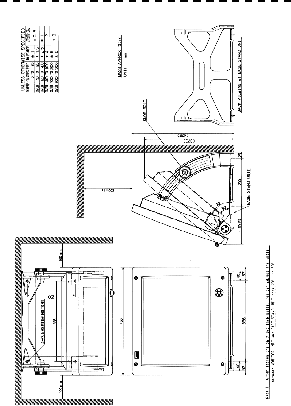
1.4 EXTERIOR DRAWINGS
Fig. 1.1 Exterior Drawing of Scanner Unit, Type NKE-2102-6
Fig. 1.2 Exterior Drawing of Scanner Unit, Type NKE-2252-7
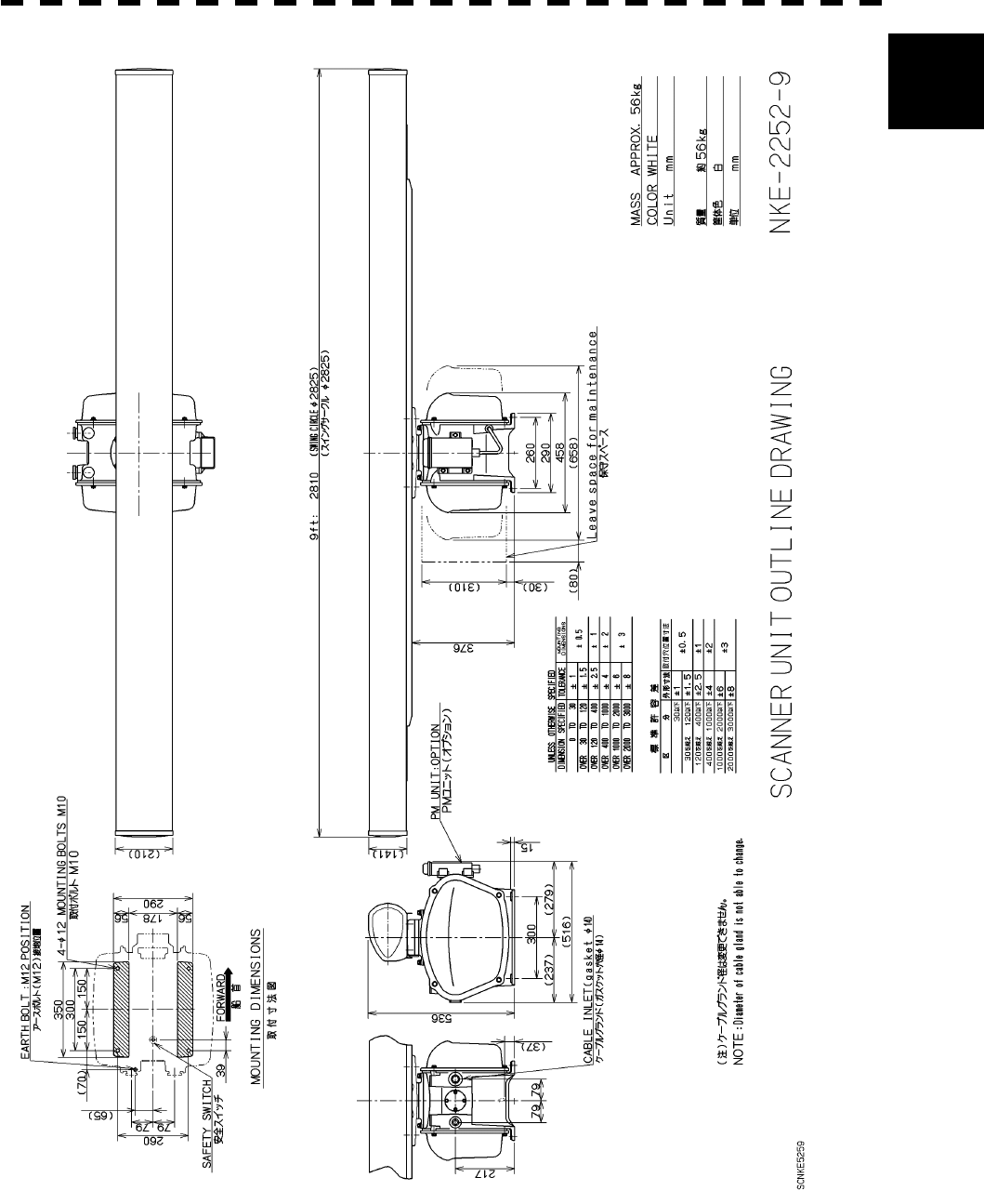
Fig. 1.3 Exterior Drawing of Scanner Unit, Type NKE-2252-9
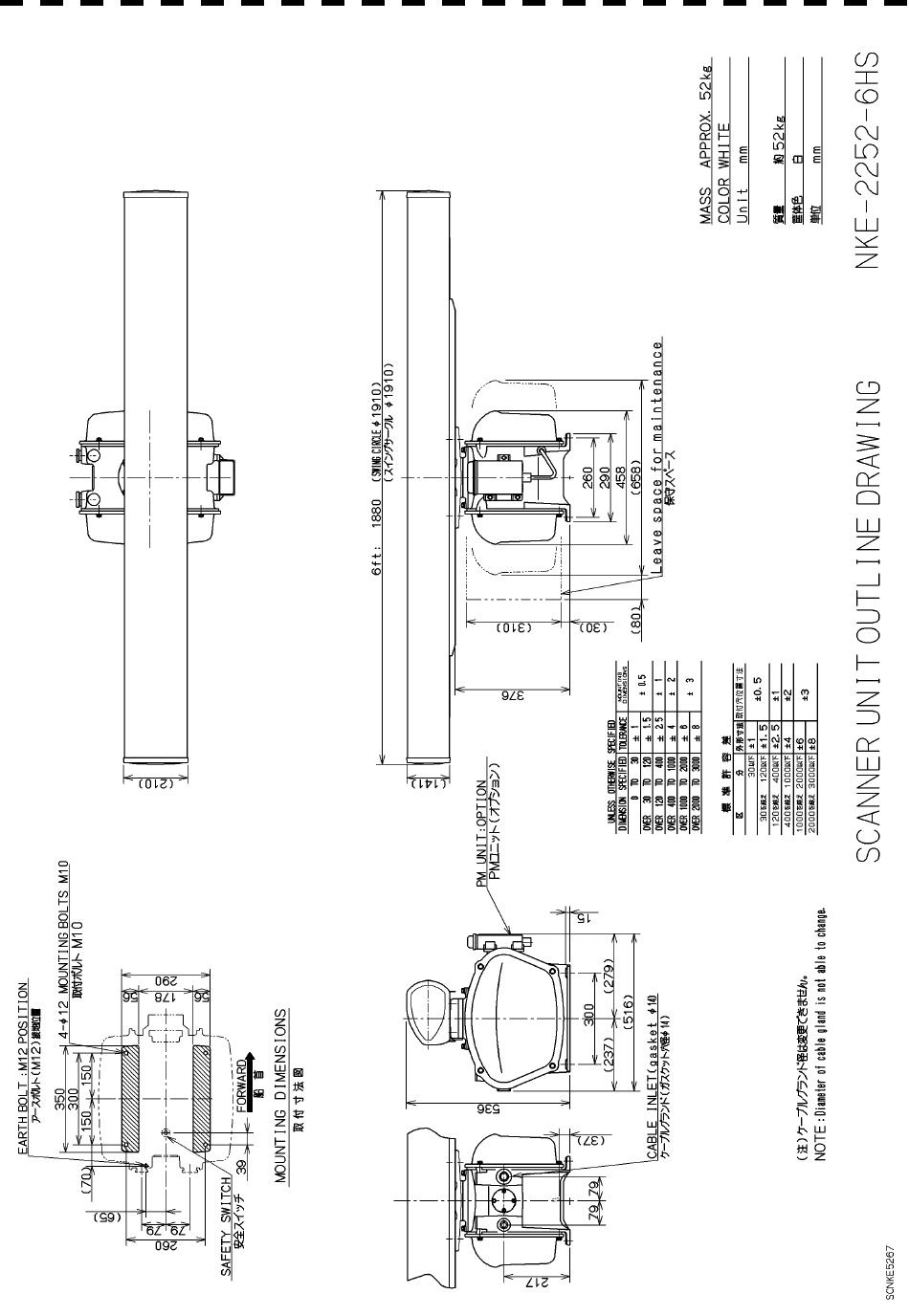
Fig. 1.4 Exterior Drawing of Scanner Unit, Type NKE-2252-6HS
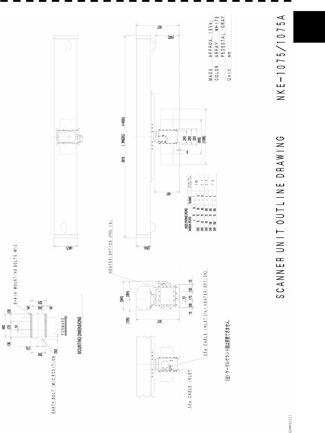
Fig. 1.5 Exterior Drawing of Scanner Unit, Type NKE-1075A
Fig. 1.6 Exterior Drawing of Display Unit, Type NWZ-147
Fig. 1.7 Exterior Drawing of Processing Unit, Type NDC-1273
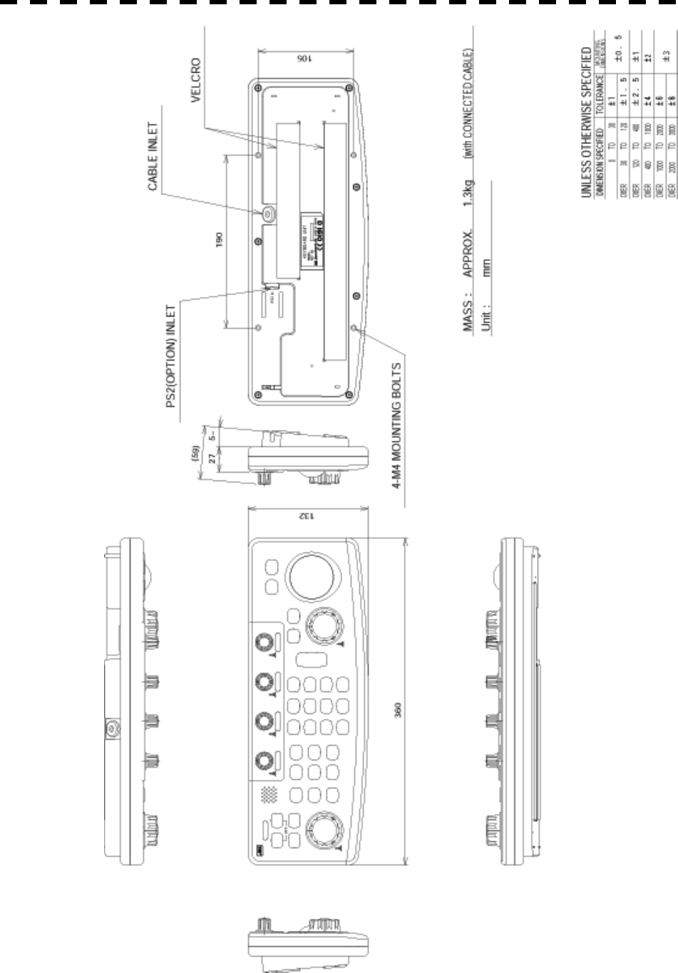
Fig. 1.8 Exterior Drawing of Operating Unit, Type NCE-7699
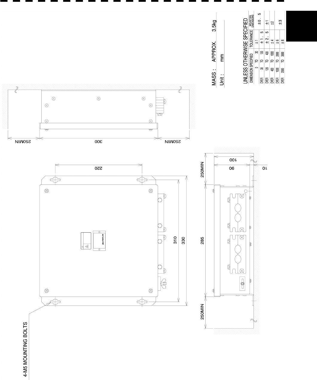
Fig. 1.9 Exterior Drawing of Connecting Unit, Type NQE-3151
1 - 6
1.4 EXTERIOR DRAWINGS
1
Fig. 1.1 Exterior Drawing of Scanner Unit, Type NKE-2102-6
1 - 7
Fig. 1.2 Exterior Drawing of Scanner Unit, Type NKE-2252-7
1 - 8
1.4 EXTERIOR DRAWINGS
1
Fig. 1.3 Exterior Drawing of Scanner Unit, Type NKE-2252-9
1 - 9
Fig. 1.4 Exterior Drawing of Scanner Unit, Type NKE-2252-6HS
1 - 10
1.4 EXTERIOR DRAWINGS
1
Fig. 1.5 Exterior Drawing of Scanner Unit, Type NKE-1075A
1 - 11
Fig. 1.6 Exterior Drawing of Display Unit, Type NWZ-147
1 - 12
1.4 EXTERIOR DRAWINGS
1
Fig. 1.7 Exterior Drawing of Processing Unit, Type NDC-1273
1 - 13
Fig. 1.8 Exterior Drawing of Operating Unit, Type NCE-7699
1 - 14
1.4 EXTERIOR DRAWINGS
1
Fig. 1.9 Exterior Drawing of Connecting Unit, Type NQE-3151

1 - 15
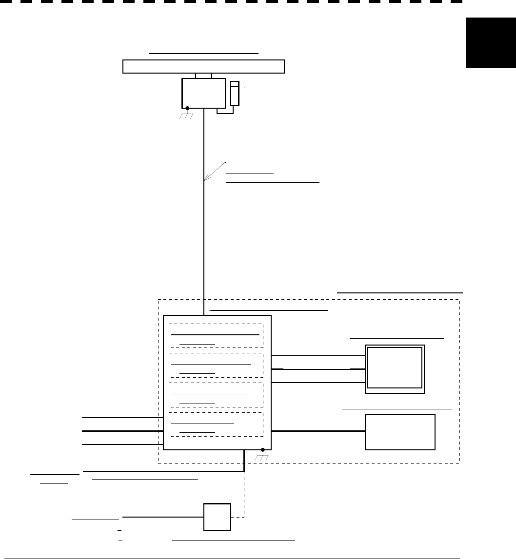
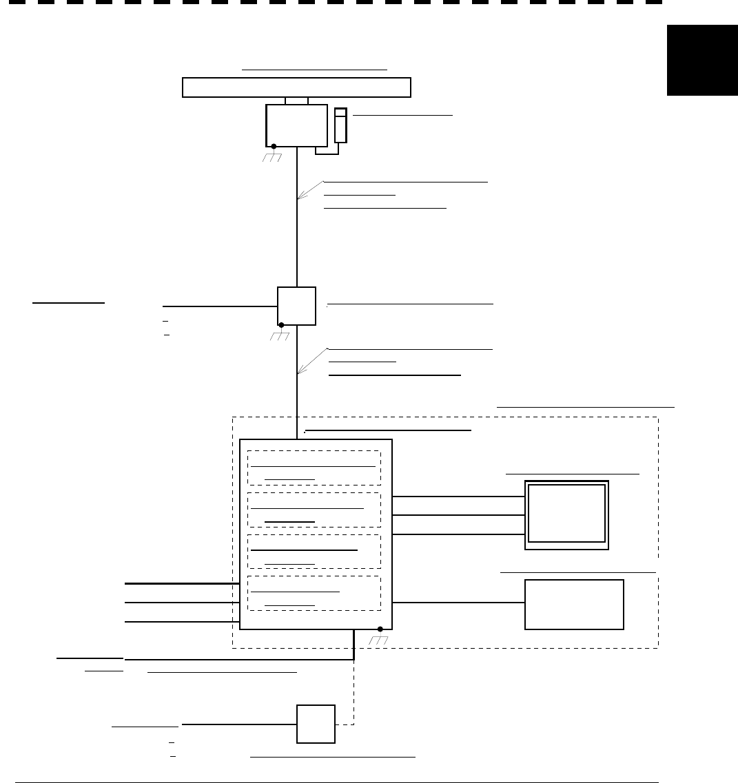
1.5 GENERAL SYSTEM DIAGRAMS
Fig. 1.10 General System Diagram of Radar, Type JMA-5310-6
Fig. 1.11 General System Diagram of Radar, Type JMA-5320-7
Fig. 1.12 General System Diagram of Radar, Type JMA-5320-9
Fig. 1.13 General System Diagram of Radar, Type JMA-5320-6HS
Fig. 1.14 General System Diagram of Radar, Type JMA-5330-12
1 - 16
1.5 GENERAL SYSTEM DIAGRAMS
1
NKE-2102-6 空中線
NJU-64 パフォーマンスモニタ
(オプション)
19芯シールド付複合ケーブル
CFQ-6912-10
最大径 φ14.5 (JRC支給)
NWZ-147 表示部
NCE-7699 操作部
NDC-1273 処理部
250V-TTYCS-1
GPS
250V-DPYCYS-1.25
LOG
250V-MPYCYS-5
GYRO NCT-59 NSK UNIT
(オプション)
NCA-877W ARPA UNIT
(オプション)
NDB-34 PLOTTER UNIT
(オプション)
船内電源
DC24V
NBA-3308 整流器
(オプション)
CFQ-6911
最大径 φ10 (JRC支給) 5m
船内電源
AC100/110/115V 50/60Hz 1φ
250V-DPYCYS-5.5
NQA-4250 AIS I/F UNIT
(オプション)
(JRC支給) 5m
(JRC支給) 5m
(JRC支給) 5m
(JRC支給) 5m
AC200/220/230V 50/60Hz 1φ
NCD-4510 指示機
Fig. 1.10 General System Diagram of Radar, Type JMA-5310-6
Note: Eliminating the interference on frequencies used for marine communications and navigation due to
operation of the radar.
All cables of the radar are to be run away from the cables of radio equipment.
(Ex. Radiotelephone. Communications receiver and direction finder, etc. )
Especially inter-wiring cables between scanner unit and display unit of the radar should not be run
parallel with the cables of radio equipment.
NJU-64 PM UNIT
NKE-2102-6 SCANNER UNIT
19 CORES COMPOSITE CABLE
CFQ-6912-20
MAX f14.5 (JRC SUPPLY)
NDC-1273 PROCESSING UNIT
NCD-4510 DISPLAY EQUIPMENT
(OPTION)
(JRC SUPPLY) 5M
(JRC SUPPLY) 5M
(JRC SUPPLY) 5M
(JRC SUPPLY) 5M
NWZ-147 DISPLAY UNIT
NCE-7699 OPERATING UNIT
SHIP’S MAIN
24 VDC MAX f10 (JRC SUPPLY) 5M
SHIP’S MAIN
NBA-3308 RECTIFIER (OPTION)
(OPTION)
(OPTION)
(OPTION)
100/110/115 VAC 50/60HZ 1f
200/220/230 VAC 50/60HZ 1f
1 - 17
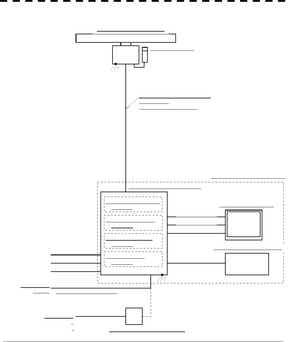
NKE-2252-7 空中線
NJU-64 パフォーマンスモニタ
(オプション)
19芯シールド付複合ケーブル
CFQ-6912-10
最大径 φ14.5 (JRC支給)
NWZ-147 表示部
NCE-7699 操作部
NDC-1273 処理部
250V-TTYCS-1
GPS
250V-DPYCYS-1.25
LOG
250V-MPYCYS-5
GYRO NCT-59 NSK UNIT
(オプション)
NCA-877W ARPA UNIT
(オプション)
NDB-34 PLOTTER UNIT
(オプション)
船内電源
DC24V
NBA-3308 整流器
(オプション)
CFQ-6911
最大径 φ10 (JRC支給) 5m
船内電源
AC100/110/115V 50/60Hz 1φ
250V-DPYCYS-5.5
NQA-4250 AIS I/F UNIT
(オプション)
(JRC支給) 5m
(JRC支給) 5m
(JRC支給) 5m
(JRC支給) 5m
AC200/220/230V 50/60Hz 1φ
NCD-4510 指示機
Fig. 1.11 General System Diagram of Radar, Type JMA-5320-7
Note: Eliminating the interference on frequencies used for marine communications and navigation due to
operation of the radar.
All cables of the radar are to be run away from the cables of radio equipment.
(Ex. Radiotelephone. Communications receiver and direction finder, etc. )
Especially inter-wiring cables between scanner unit and display unit of the radar should not be run
parallel with the cables of radio equipment.
NJU-64 PM UNIT
NKE-2252-7 SCANNER UNIT
19 CORES COMPOSITE CABLE
CFQ-6912-20
MAX f14.5 (JRC SUPPLY)
NDC-1273 PROCESSING UNIT
NCD-4510 DISPLAY EQUIPMENT
(JRC SUPPLY) 5M
(JRC SUPPLY) 5M
(JRC SUPPLY) 5M
(JRC SUPPLY) 5M
NWZ-147 DISPLAY UNIT
NCE-7699 OPERATING UNIT
SHIP’S MAIN
24 VDC MAX f10 (JRC SUPPLY) 5M
SHIP’S MAIN
NBA-3308 RECTIFIER (OPTION)
(OPTION)
(OPTION)
(OPTION)
(OPTION)
100/110/115 VAC 50/60HZ 1f
200/220/230 VAC 50/60HZ 1f
1 - 18
1.5 GENERAL SYSTEM DIAGRAMS
1
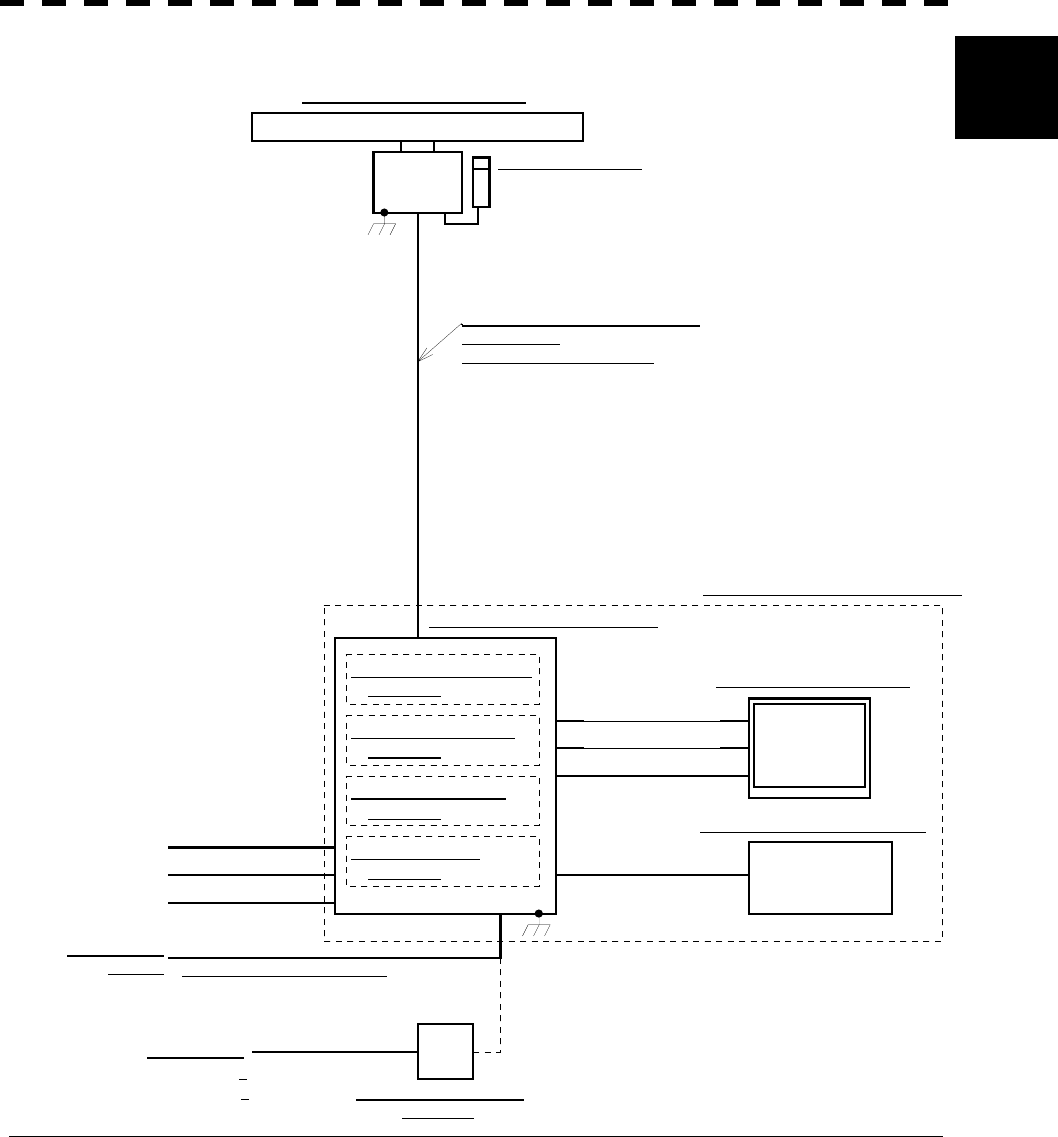
NKE-2252-9 空中線
NJU-64 パフォーマンスモニタ
(オプション)
19芯シールド付複合ケーブル
CFQ-6912-10
最大径 φ14.5 (JRC支給)
NWZ-147 表示部
NCE-7699 操作部
NDC-1273 処理部
250V-TTYCS-1
GPS
250V-DPYCYS-1.25
LOG
250V-MPYCYS-5
GYRO NCT-59 NSK UNIT
(オプション)
NCA-877W ARPA UNIT
(オプション)
NDB-34 PLOTTER UNIT
(オプション)
船内電源
DC24V
NBA-3308 整流器
(オプション)
CFQ-6911
最大径 φ10 (JRC支給) 5m
船内電源
AC100/110/115V 50/60Hz 1φ
250V-DPYCYS-5.5
NQA-4250 AIS I/F UNIT
(オプション)
(JRC支給) 5m
(JRC支給) 5m
(JRC支給) 5m
(JRC支給) 5m
AC200/220/230V 50/60Hz 1φ
NCD-4510 指示機
Fig. 1.12 General System Diagram of Radar, Type JMA-5320-9
Note: Eliminating the interference on frequencies used for marine communications and navigation due to
operation of the radar.
All cables of the radar are to be run away from the cables of radio equipment.
(Ex. Radiotelephone. Communications receiver and direction finder, etc. )
Especially inter-wiring cables between scanner unit and display unit of the radar should not be run
parallel with the cables of radio equipment.
NKE-2252-9 SCANNER UNIT
19 CORES COMPOSITE CABLE
CFQ-6912-20
MAX f14.5 (JRC SUPPLY)
NDC-1273 PROCESSING UNIT
NCD-4510 DISPLAY EQUIPMENT
(JRC SUPPLY) 5M
(JRC SUPPLY) 5M
(JRC SUPPLY) 5M
(JRC SUPPLY) 5M
NWZ-147 DISPLAY UNIT
NCE-7699 OPERATING UNIT
SHIP’S MAIN
24 VDC MAX f10 (JRC SUPPLY) 5M
SHIP’S MAIN
NBA-3308 RECTIFIER
(OPTION)
(OPTION)
(OPTION)
(OPTION)
(OPTION)
100/110/115 VAC 50/60HZ 1f
200/220/230 VAC 50/60HZ 1f
NJU-64 PM UNIT
1 - 19
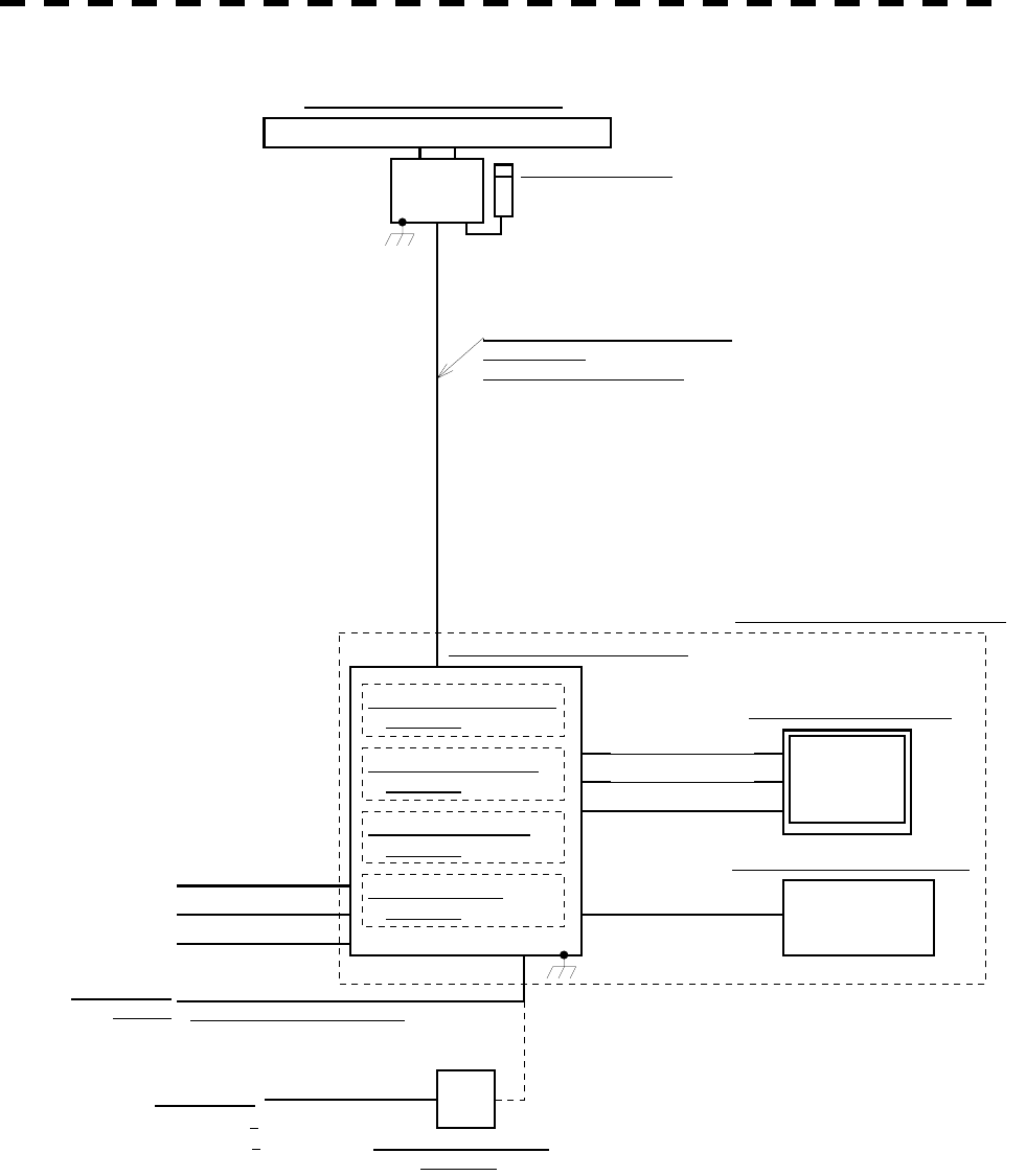
NKE-2252-9 空中線
NJU-64 パフォーマンスモニタ
(オプション)
19芯シールド付複合ケーブル
CFQ-6912-10
最大径 φ14.5 (JRC支給)
NWZ-147 表示部
NCE-7699 操作部
NDC-1273 処理部
250V-TTYCS-1
GPS
250V-DPYCYS-1.25
LOG
250V-MPYCYS-5
GYRO NCT-59 NSK UNIT
(オプション)
NCA-877W ARPA UNIT
(オプション)
NDB-34 PLOTTER UNIT
(オプション)
船内電源
DC24V
NBA-3308 整流器
(オプション)
CFQ-6911
最大径 φ10 (JRC支給) 5m
船内電源
AC100/110/115V 50/60Hz 1φ
250V-DPYCYS-5.5
NQA-4250 AIS I/F UNIT
(オプション)
(JRC支給) 5m
(JRC支給) 5m
(JRC支給) 5m
(JRC支給) 5m
AC200/220/230V 50/60Hz 1φ
NCD-4510 指示機
Fig. 1.13 General System Diagram of Radar, Type JMA-5320-6HS
Note: Eliminating the interference on frequencies used for marine communications and navigation due to
operation of the radar.
All cables of the radar are to be run away from the cables of radio equipment.
(Ex. Radiotelephone. Communications receiver and direction finder, etc. )
Especially inter-wiring cables between scanner unit and display unit of the radar should not be run
parallel with the cables of radio equipment.
NKE-2252-6HS SCANNER UNIT
19 CORES COMPOSITE CABLE
CFQ-6912-20
MAX f14.5 (JRC SUPPLY)
NDC-1273 PROCESSING UNIT
NCD-4510 DISPLAY EQUIPMENT
(JRC SUPPLY) 5M
(JRC SUPPLY) 5M
(JRC SUPPLY) 5M
(JRC SUPPLY) 5M
NWZ-147 DISPLAY UNIT
NCE-7699 OPERATING UNIT
SHIP’S MAIN
24 VDC MAX f10 (JRC SUPPLY) 5M
SHIP’S MAIN
NBA-3308 RECTIFIER
(OPTION)
(OPTION)
(OPTION)
(OPTION)
(OPTION)
100/110/115 VAC 50/60HZ 1f
200/220/230 VAC 50/60HZ 1f
NJU-64 PM UNIT
1 - 20
1.5 GENERAL SYSTEM DIAGRAMS
1
NKE-1075 空中線
NJU-63 パフォーマンスモニタ
(オプション)
14芯シールド付複合ケーブル
H-2695110056
最大径 φ23 (JRC支給)
NQE-3151 接続ユニット660V-DPYCYS-5.5
AC100/110V 50/60Hz 1φ
AC220/230V 50/60Hz 1φ
船内電源
19芯シールド付複合ケーブル
CFQ-6912-10
最大径 φ14.5 (JRC支給)
NWZ-147 表示部
NCE-7699 操作部
NDC-1273 処理部
250V-TTYCS-1
GPS
250V-DPYCYS-1.25
LOG
250V-MPYCYS-5
GYRO NCT-59 NSK UNIT
(オプション)
NCA-877W ARPA UNIT
(オプション)
NDB-34 PLOTTER UNIT
(オプション)
船内電源
DC24V
NBA-3308 整流器
(オプション)
CFQ-6911
最大径 φ10 (JRC支給) 5m
船内電源
AC100/110/115V 50/60Hz 1φ
250V-DPYCYS-5.5
NQA-4250 AIS I/F UNIT
(オプション)
(JRC支給) 5m
(JRC支給) 5m
(JRC支給) 5m
(JRC支給) 5m
AC200/220/230V 50/60Hz 1φ
NCD-4510 指示機
Fig. 1.14 General System Diagram of Radar, Type JMA-5330-12
Note: Eliminating the interference on frequencies used for marine communications and navigation due to
operation of the radar.
All cables of the radar are to be run away from the cables of radio equipment.
(Ex. Radiotelephone. Communications receiver and direction finder, etc. )
Especially inter-wiring cables between scanner unit and display unit of the radar should not be run
parallel with the cables of radio equipment.
NKE-1075 SCANNER UNIT
14 CORES COMPOSITE CABLE
H-2695110056
MAX f23 (JRC SUPPLY)
NDC-1273 PROCESSING UNIT
NCD-4510 DISPLAY EQUIPMENT
(JRC SUPPLY) 5M
(JRC SUPPLY) 5M
(JRC SUPPLY) 5M
(JRC SUPPLY) 5M
NWZ-147 DISPLAY UNIT
NCE-7699 OPERATING UNIT
SHIP’S MAIN
24 VDC MAX f10 (JRC SUPPLY) 5M
SHIP’S MAIN
NBA-3308 RECTIFIER (OPTION)
(OPTION)
(OPTION)
(OPTION)
(OPTION)
SHIP’S MAIN NQE-3151 CONNECTING UNIT
19 CORES COMPOSITE CABLE
CFQ-6912-20
MAX f14.5 (JRC SUPPLY)
100/110/115 VAC 50/60HZ 1f
200/220/230 VAC 50/60HZ 1f
100/110/115 VAC 50/60HZ 1f
200/220/230 VAC 50/60HZ 1f
NJU-63 PM UNIT

SECTION 2
NAMES AND FUNCTIONS OF
CONTROL PANEL KEYS
AND FUNCTIONS OF SOFTWARE BUTTONS
2.1 NAMES AND FUNCTIONS OF CONTROL
PANEL KEYS..................................................2-1
2.2 FUNCTIONS OF SOFTWARE BUTTONS .....2-7
2─1
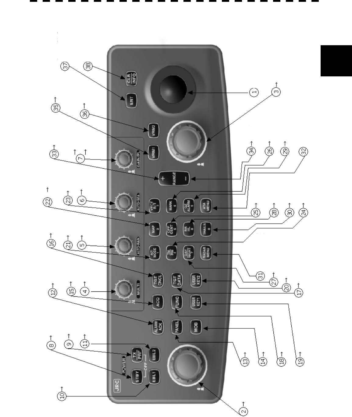
2.1 NAMES AND FUNCTIONS OF CONTROL
PANEL KEYS
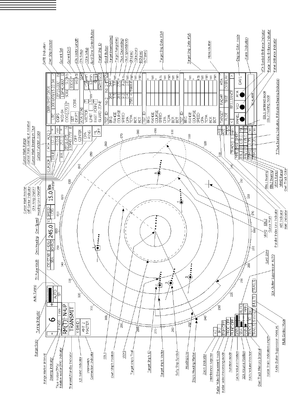
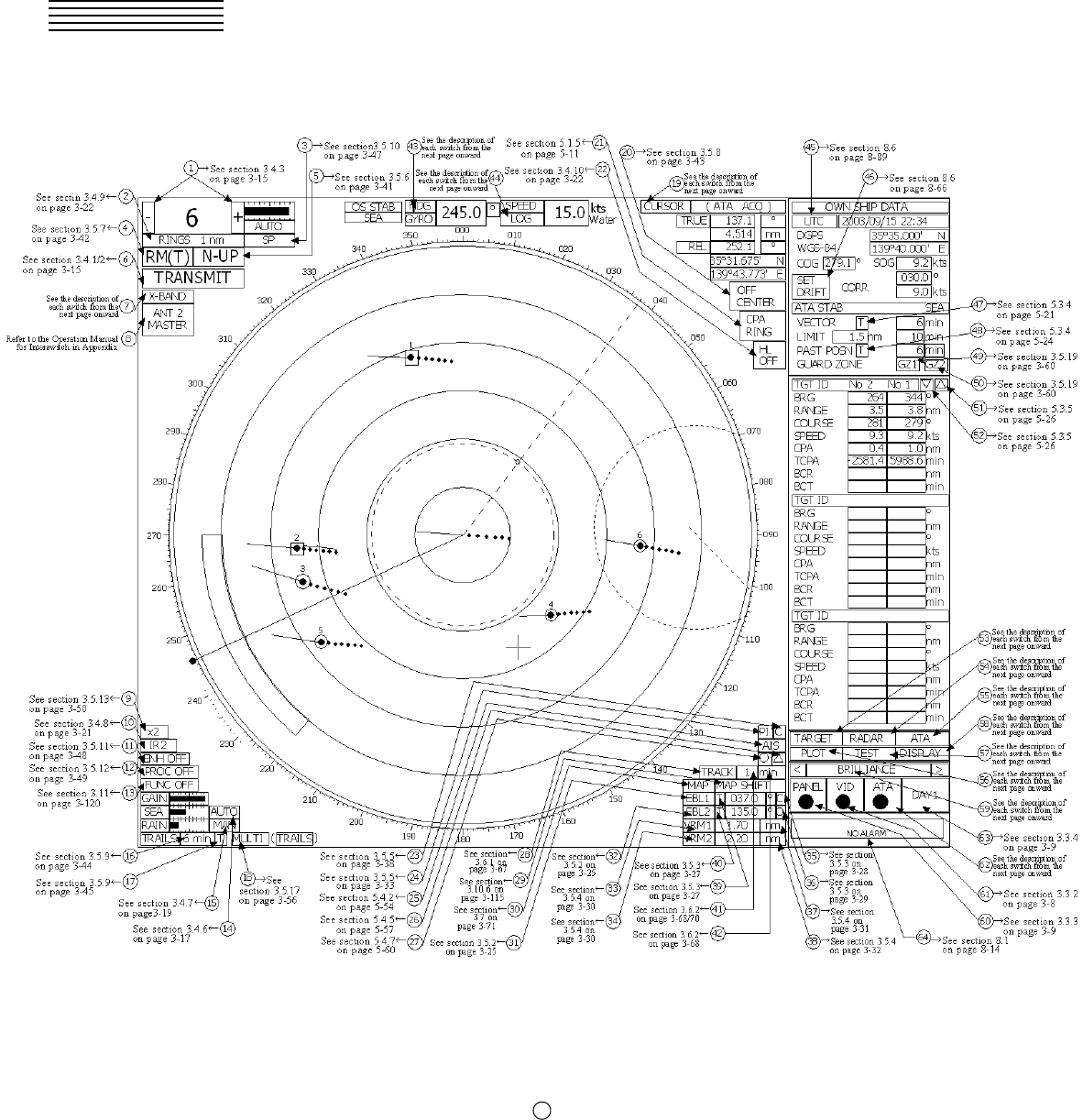
Example of Display
2─2
2
2.1 NAMES AND FUNCTIONS OF CONTROL
Names and Functions of Control Panel Keys
The following page describe name of buttons. The Sections and page numbers on the above indicate
pages where operation procedures and detailed descriptions are provided.
See the description
of each switch from
the next page
onward.
See section 3.5.4
on page 3-30.
See the description
of each switch from
the next page
onward.
See the description
of each switch from
the next page
onward.
See section
3.4.3 on page
3-15.
See section 3.5.15
on page 3-52.
See the description
of each switch from
the next page
onward.
See section
3.5.8 on page
3-.43
See section
3.4.9/10 on
p
age 3-22.
See section
3.5.9 on page
3-44.
See section
3.5.7 on page
3-42.
See the
description of each
switch from the next
p
age onward.
See section 3.3.4
on page 3-9.
See section 3.5.18
on page 3-58.
See section 5.3.5
on page 5-26.
See section
3.3.3 on
p
age 3-9.
See section
3.5.14 on page
3-51.
See section 3.11
on page 3-120.
See section 3.5.18
on page 3-58.
See section 3.5.2
on page 3-25.
See section
3.5.2 on page
3-25.
See section
3.4.2 on page
3-15.
See section
3.4.1 on page
3-15.
See section
3.5.2 on page
3-25.
See section 3.3.7
on page 3-11.
See section
5.3.1 on
page 5-17.
See section
3.5.17 on
p
age 3-56.
See section
5.3.2 on
page 5-19.
See section
3.5.6 on
p
age 3-41.
See section
3.4.7 on
page 3-19.
See section
3.7 on page
3-71.
See section
5.3.4 on
p
age 5-21.
See section
3.4.6 on
page 3-17.
See section
3.4.3 on
page 3-15.
See section
3.4.5 on
page 3-16.
See section
3.5.10 on
p
age 3-47.
See section
3.5.4 on
page 3-30.
See section
3.5.4 on
page 3-31.
See section 5.1.6
on page 5-12.

2─3
① Trackball
Use this trackball to move the cursor mark to an arbitrary point. The trackball can be used for
setting in each mode.
For example, use it to specify the center of a floating EBL or the off-center position.
®For setting cursor, see section 3.10.3 on page 3-102.
② [EBL] (Electric Bearing Line) Control
Rotates the bearing of an EBL.
The selected EBL status switches back and forth between “center fixed” and “floating” each time
the control is pressed.
®See section 3.5.2 on page 3-25.
③ [VRM] (Variable Range Marker) Control
Changes the range of a VRM.
®See section 3.5.4 on page 3-30.
④ [MULTI] (Multi-function) Control
Each time you press this control, you can change items registered in the multi-function control
function.
An item to switch to is shown put in parentheses in the lower left area of the screen. Give a long
press of the control to open the setup screen for registering items. Give a long press of the control
button again to close this setup screen.
®See section 3.5.17 on page 3-56.
⑤ [AUTO-RAIN] (Rain/Snow Clutter Suppression) Control
Suppresses the clutter echo from rain or snow.
To heighten a suppressing effect, turn the control clockwise.
The clutter suppression mode switches back and forth between MANUAL and AUTO each
time the control is pressed.
®See section 3.4.7 on page 3-19.
⑥ [AUTO-SEA] (Sea Clutter Suppression) Control
Suppresses the clutter echo from the sea surface.
To heighten a suppressing effect, turn the control clockwise.
The clutter suppression mode switches back and forth between MANUAL and AUTO each
time the control is pressed.
®See section 3.4.6 on page 3-17.
⑦ [GAIN/PL] (Receiving Sensitivity/Pulse Width) Control
Controls the radar’s receiving sensitivity.
To get higher sensitivity, turn the control clockwise.
To change the transmitter pulse width, press the control.
®For sensitivity, see section 3.4.5 on page 3-16.
®For pulse width, see section 3.5.10 on page 3-47.
⑧ [STBY] (Standby) Key
Use this key to change the power-off state to the power-on state, or the transmission state to the
standby state.
To turn off the power, press the [STBY] key and [TX/PRF] key together.
®See section 3.4.2 on page 3-15.
⑨ [TX/PRF] (Transmit/Transmitting Repetition Frequency) Key
PREHEAT at the upper left of the radar display changes to STANDBY about three minutes
after the power is turned on.
Then, press this key to start transmission.
To fine-tune the transmitting repetition frequency, press the key during transmission.

2─4
2
2.1 NAMES AND FUNCTIONS OF CONTROL
Use of this function with the interference rejector function heightens an interference suppressing
effect.
®See section 3.4.1 on page 3-15.
⑩ [EBL1] (Electric Bearing Line 1) Key
Use this key to display and select EBL1.
Holding down the key for two seconds or more displays the menu for EBL1 setting.
®See section 3.5.2 on page 3-25.
®For EBL1 setting, see section 3.5.3 on page 3-27 onward.
⑪ [EBL2] (Electric Bearing Line 2) Key
Use this key to display and select EBL2.
Holding down the key for two seconds or more displays the menu for EBL2 setting.
®See section 3.5.2 on page 3-25.
®For EBL2 setting, see section 3.5.3 on page 3-27 onward.
⑫ [ALARM ACK] (Alarm Acknowledgment) Key
Use this key to acknowledge a failure, target’s approach, or collision alarm.
Press the key to stop an audible alarm.
If more than one alarm has occurred, the key needs to be pressed the number of times equivalent to
the number of alarms.
®See section 3.3.7 on page 3-11.
⑬ [PANEL] (Operation Panel Brilliance) Key
Controls the brilliance for the controls and Keys on the operation panel.
The brilliance changes cyclically each time the key is pressed.
®See section 3.3.3 on page 3-9.
⑭ [MOB] (Marker) Key
A marker is set to the latitude and longitude of the own ship’s position at the point of pressing this
key.
For example, use the key to store the own ship’s position at the moment when somebody falls from
the ship.
Holding down the key for two seconds or more erases the marker.
®See section 3.5.14 on page 3-51.
⑮ [ACQ] (Manual Acquisition) Key
Enables the manual ATA acquisition mode for the target on which the cursor sits.
®See section 5.3.1 on page 5-17.
⑯ [TGT CNCL] (Tracking Target Cancel) Key
Cancels the symbol and vector of a target under tracking, and stops tracking the target.
Holding down the key for two seconds or more erases all the acquisitions of ATA.
®See section 5.3.2 on page 5-19.
⑰ [TGT DATA] (Target Data Setup) Key
Use this key to view the numeric data of the ATA under tracking or the currently displayed AIS.
®See section 5.3.5 on page 5-26.

2─5
⑱ [FUNC] (Function Call) Key
Calls predefined signal processing setting when pressed.
The selection changes in the following sequence each time the key is pressed:
Function Off ® Function 1 ® Function 2 ® Function 3 ® Function 4 ®
Function Off
Holding down the key for two seconds or more displays the function setting menu.
®See section 3.11 on page 3-120.
⑲ [USER KEY1] (User Registration 1) Key
Directly displays a pre-registered menu position when pressed.
®See section 3.5.18 on page 3-58.
⑳ [USER KEY2] (User Registration 2) Key
Directly displays a pre-registered menu position when pressed.
®See section 3.5.18 on page 3-58.
[AZI MODE] [1] (Bearing Mode Select/1) Key
Selects the North-up (true bearing), Head-up (relative bearing), or Course-up bearing display mode.
This key serves as the numeric key [1] during menu operation.
®See section 3.5.6 on page 3-41.
[MAP] [2] (Map Display/2) Key
Selects whether to display charts, shorelines or depth contours on the radar map.
This key serves as the numeric key [2] during menu operation.
®For displaying charts, see section 3.7 on page 3-71 onward.
[VECT R/T] [3] (Vector Mode/3) Control
Selects the ATA vector display mode (true/relative).
This key serves as the numeric key [3] during menu operation.
®See section 5.3.4 on page 5-21.
[TM/RM] [4] (True Motion/Relative Motion) Key
Switches back and forth between the TM display mode and RM display mode.
This key serves as the numeric key [4] during menu operation.
®See section 3.5.7 on page 3-42.
[OFF CENT] [5] (Off Center/5) Key
Shifts the own ship’s position within a desired direction (within 66% of the scope’s radius) from the
scope’s center to expand the display portion.
This key serves as the numeric key [5] during menu operation.
®See section 3.5.8 on page 3-43.
[MARK] [6] (Mark/6) Key
Displays a mark at an arbitrary position or erases the mark on the display.
This key serves as the numeric key [6] during menu operation.
®See section 3.5.15 on page 3-52.
[DAY/NIGHT] [7] (Day/Night Mode Select/7) Key
Selects a preset color and brilliance of the display screen.
This key serves as the numeric key [7] during menu operation.
®See section 3.3.4 on page 3-9.
21
22
23
24
25
27
26

2─6
2
2.1 NAMES AND FUNCTIONS OF CONTROL
[RR/HL] [8] (Fixed Range Marker/Heading Line Off/8) Key
The ship’s HL (heading line) is erased while this key is held down.
The fixed range marker display switches back and forth between display and non-display
each time the key is pressed.
This key serves as the numeric key [8] during menu operation.
®For displaying Fixed Range Marker, see section 3.4.9 on page 3-22.
®For Heading Line Off, see section 3.4.10 on page 3-22.
[GZ ALARM] [9] (Guard Zone/9) Key
Sets a guard zone on the radar display.
This key serves as the numeric key [9] during menu operation.
®See section 5.1.6 on page 5-12.
[TRAILS] [0] (Radar Trails/0) Key
The radar trails time length is switched each time the key is pressed.
This key serves as the numeric key [0] during menu operation.
®See section 3.5.9 on page 3-44.
[RADAR MENU] (Radar Menu) Key
Displays the radar menu when pressed.
[ATA MENU] (ATA Menu) Key
Displays the ATA menu when pressed.
[RANGE+] (Range Scale +) Key
Expands the observation range scale when pressed.
®See section 3.4.3 on page 3-15.
[RANGE-] (Range Scale -) Key
Shrinks the observation range scale when pressed.
®See section 3.4.3 on page 3-15.
[VRM1] (Variable Range Marker 1) Key
Use this key to display and select VRM1.
Holding down the key for two seconds or more displays the menu for VRM1 setting.
®See section 3.5.4 on page 3-30.
®For VRM1 setting, see page 3-31.
[VRM2] (Variable Range Marker 2) Key
Use this key to display and select VRM2.
Holding down the key for two seconds or more displays the menu for VRM2 setting.
®See section 3.5.4 on page 3-31.
®For VRM2 setting, see page 3-32.
[ENT] (Enter) Key
Use this key to determine menu selection or value input.
Pressing the key has the same effect as left-clicking the trackball.
[CLR/INFO] (Clear/Information) Key
Use this key to cancel menu selection or value input.
Pressing the key has the same effect as right-clicking the trackball
28
29
30
31
32
33
34
35
36
37
38
2─7
2.2 FUNCTIONS OF SOFTWARE BUTTONS
This radar provides the software buttons on the display which can be used to set several important functions
directly and swiftly from the display without opening the corresponding menu.
The names of buttons are described on the following pages. See the following pages. The Sections and page
numbers on the above indicate pages where operation procedures and detailed descriptions are provided.
A-4 size screen pages are also provided in the appendix at the end of this description.
By positioning the arrow cursor to a button at to in the figure above and then clicking the left button of
the trackball, the setting can be changed as shown below.
64
2─8
2
2.2 FUNCTIONS OF SOFTWARE BUTTONS
①: Range selection
Switches a radar range.
“+”: Increments the range scale. (96 or 120 nm at maximum)
“-”: Decrements the range scale. (0.125 nm at minimum)
®See section 3.4.3 on page 3-15.
②: Selection of RINGS display
Turns on/off the fixed range marker display. While it is on, the range ring interval is displayed.
While it is off, “OFF” is displayed.
®See section 3.4.9 on page 3-22.
③: Selection of transmitter pulse width
Selects a transmitter pulse width. There are three types of pulses, short pulse (SP), middle pulse
(MP), and long pulse (LP). The pulse width to be selected varies depending on the current range.
If the pulse width cannot be changed, the display disappears. The pulse width setting is stored for
each range.
®See section 3.5.10 on page 3-47.
④: Selection of motion mode
Selects the true motion (TM) or relative motion (RM) mode for the radar display.
The display switches back and forth between “TM” and “RM” each time the button is clicked.
RM (R) indicates relative trails; RM (T) indicates true trails.
®See section 3.5.7 on page 3-42.
⑤: Selection of bearing mode
Selects North-up (true bearing), Head-up (relative bearing), or Course-up bearing mode.
This button operates similarly to the “AZI MODE” key.
The selection changes in the following sequence each time the button is clicked:
N UP Þ C UP Þ H UP
®See section 3.5.6 on page 3-41.
⑥: Selection of Transmit/Standby
PREHEAT at the upper left of the radar display changes to STANDBY about three minutes
after the power is turned on.
STANDBY : Indicates the standby state. Clicking the button in this state changes to the
transmission state.
TRANSMIT : Indicates the transmission state. Clicking the button in this state changes to the
standby state.
®For how to start transmission, see Section 3.4.1 on page 3-15.
®For how to stop transmission, see Section 3.4.2 on page 3-15.
⑦: Indication of band
This button is fixed depending on the type of the antenna. X-BAND or S-BAND is
displayed.
⑧: Change of interswitch connection
This button is displayed when an interswitch is connected. The display indicates the connection
between the indicator and the scanner. Clicking the button displays the menu for changing the
indicator-scanner connection.
The indicator-scanner connection cannot be changed unless the master indicator is in standby state.
®For the setting procedure, refer to the Operation Manual for Interswitch in Appendix. The
interswitch is an option. Only when an interswitch is connected, this button is to be displayed.
⑨: Zoom selection
Doubles the size of display specified with the cursor.
®See section 3.5.13 on page 3-50.
2─9
⑩: Selection of radar interference rejector function
Turns on/off the radar interference rejector function (IR). The selection changes in the following
sequence each time the button is clicked.
IR OFF ® IR LOW ® IR MEDIUM ® IR HIGH
®See section 3.4.8 on page 3-21.
⑪: Selection of radar video enhance function (ENH)
Turns on/off the radar video enhance function. The selection changes in the following sequence
each time the button is clicked:
ENH OFF ® ENH LEVEL1 ® ENH LEVEL2 ® ENH LEVEL3
®See section 3.5.11 on page 3-48.
⑫: Selection of radar video processing function (PROC)
Selects a video processing mode. The selection changes in the following sequence each time
the button is clicked:
PROC OFF ® 3SCAN CORR ® 4SCAN CORR ® 5SCAN CORR ®
REMAIN ® PEAK HOLD
®See section 3.5.12 on page 3-49.
⑬: Selection of processing setting function (FUNC)
Selects a processing setting mode. The selection changes in the following sequence each time
the button is clicked:
FUNC OFF ® FUNC1 ® FUNC2 ® FUNC3 ® FUNC4
The currently selected function mode name is shown on the button.
®See section 3.11 on page 3-120.
⑭: Selection of MANUAL/AUTO for sea clutter suppression function (SEA)
Selects whether to use the sea clutter suppression function in manual or automatic mode. The
bar shown at left indicates the control setting position.
®See section 3.4.6 on page 3-17.
⑮: Selection of MANUAL/AUTO for rain/snow clutter suppression function (RAIN)
Selects whether to use the rain/snow clutter suppression function in manual or automatic mode.
The bar shown at left indicates the control setting position.
®See section 3.4.7 on page 3-19.
⑯: Selection of radar trail display function (TRAILS)
Sets up the trail time of the radar to be displayed. The setting of trail time can be changed.
®See section 3.5.9 on page 3-44.
®For the selection of trail time length, see section 3.10.2 on page 3-85.
⑰: Selection of radar trail mode
Selects the true-motion trail mode or relative-motion trail mode in which the radar trail function
is to operate.
T is displayed when the true-motion trail mode is selected; R is displayed when the
relative-motion trail mode is selected.
This selection is limited by the radar video motion mode.
While relative motion (RM) is indicated, the true-motion trail mode or relative-motion trail mode
can be selected.
While true motion (TM) is indicated, only the true-motion trail mode can be selected.
®See section 3.5.9 on page 3-45.
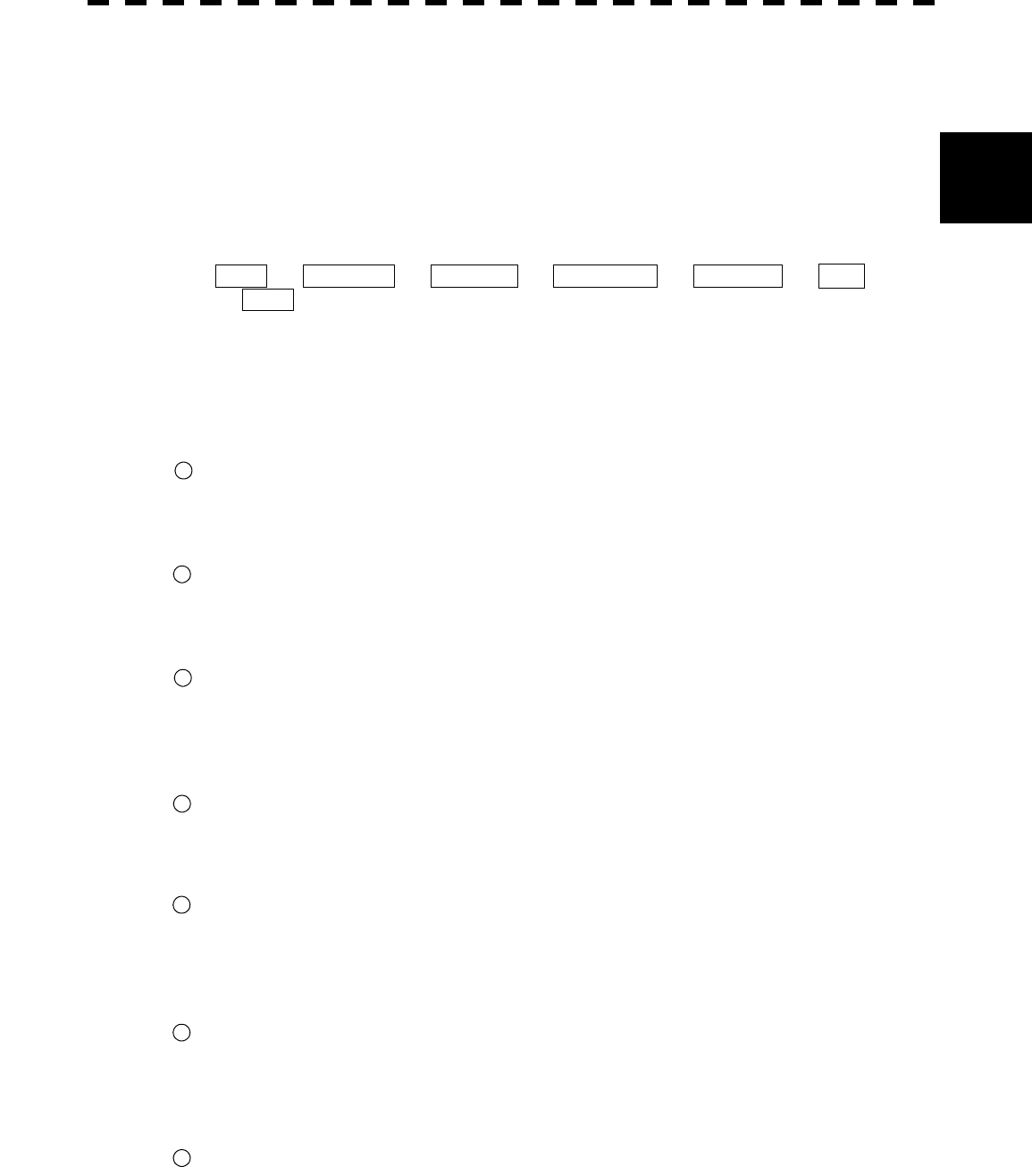
2─10
2
2.2 FUNCTIONS OF SOFTWARE BUTTONS
⑱: Multi-function Control Mode
Each time you press this button, you can change the item registered in the multi-function control
function.
A switched item is displayed put in parentheses. Give a long press of the control to open the
setup screen for registering items. Give a long press of the control button again to close this
setup screen.
®See section 3.5.17 on page 3-56.
⑲: Cursor mode selection
Selects a mode in which the cursor is to move. The selection changes in the following sequence
each time the button is clicked:
OFF ® ACQ ATA ® ACT AIS ® TGT DATA ® CANCEL ® □
® OFF
⑳: Selection of off-center mode
This button operates similarly to the [OFF CENT] key. To shift the center of the own ship to
the cursor position, press the button to move the cursor and left-click. The center of the own
ship can be shifted within 66% of the scope’s radius.
®See section 3.5.8 on page 3-43.
: Selection of CPA RING display
Turns on/off the CPA RING display.
CPA RING cannot be turned on while TRUE is selected for the vector mode.
®See section 5.1.5 on page 5-11.
: Selection of HL Off
This button operates similarly to the [RR/HL] key.
The heading line (HL) display is off while the button is held down.
®See section 3.4.10 on page 3-22.
: Starting point mode of parallel cursor
Determines whether the starting point of parallel cursor is placed at the center of the own ship or
at an arbitrary position on the radar display screen.
You can select from the following three types: C: CENTER, 0: OFFSET, and L: L/L FIX.
®See section 3.5.5 on page 3-38.
: Selection of parallel index line display
Turns on/off the parallel index line display. The selection (on/off) changes each time the button
is pressed.
®See section 3.5.5 on page 3-33.
: Selection of AIS display function
Turns on/off the AIS display function. The selection status is changed each time the button is
pressed.
®See section 5.4.2 on page 5-54.
* This function is available only when the AIS I/F (option) is connected.
: Selection of AIS symbol display
Turns on/off the AIS symbol display. The selection (on/off) changes each time the button is
pressed.
®See section 5.4.5 on page 5-57.
* This function is available only when the AIS I/F (option) is connected.
: Selection of ARPA symbol display
Turns on/off the ARPA symbol display to distinguish the symbol from the AIS symbol. The
selection changes each time the button is pressed.
®See section 5.4.7 on page 5-60.
* This function is available only when the AIS I/F (option) is connected.
21
27
22
23
24
25
26
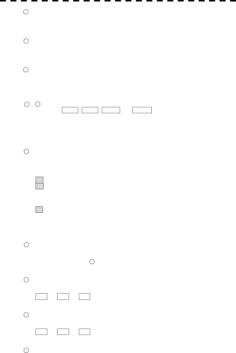
2─11
: Selection of own ship’s track display function (TRACK)
Turns on/off the own ship’s track display function, and enables the setting of track memory
intervals.
®See section 3.6.1 on page 3-67.
: Selection of map display position correction
Turns on/off the map display position correction. The setup menu is open each time the button
is pressed.
®See section 3.10.6 on page 3-115.
: Selection of map display
Turns on/off the map display. The selection (on/off) changes each time the button is pressed.
A card containing map information needs to be inserted into the card slot in the processor in
advance.
®See section 3.7 on page 3-71.
- : EBL and VRM setting
The buttons EBL1 , EBL2 , VRM1 , and VRM2 are provided to turn on/off the display
and get operation authority.
They operate similarly to the keys [EBL1], [EBL2], [VRM1], and [VRM2] on the control panel.
To move an EBL or VRM, use the control on the panel.
®For turning on/off EBL, see section 3.5.2 on page 3-25.
®For turning on/off VRM, see section 3.5.4 on page 3-30.
: Starting point mode of EBL1
Determines whether the EBL1 starting point is placed at the center of the own ship or at an
arbitrary position on the radar display.
The [EBL] control on the control panel operates similarly to this button.
C : CENTER indicates that the EBL1 starting point is placed at the center of the own ship.
O : OFFSET indicates that the EBL1 starting point is not placed at the center of the own ship.
In this status, the starting point is at the cursor position or is fixed to an arbitrary position
on the radar display. The starting point becomes the cursor position when the button is
clicked, and it is fixed to the cursor position when the button is left-clicked subsequently.
L : L/L FIX indicates that after the EBL1 starting point is moved, the latitude and longitude at
the starting point are fixed.
When the starting point gets out of the radar display, the reset function automatically works for
the starting point to return to the center of the own ship.
®See section 3.5.3 on page 3-28.
: Starting point mode of EBL2
Determines whether the EBL2 starting point is placed at the center of the own ship or at an
arbitrary position on the radar display.
For other information, see Starting point mode of EBL1.
®See section 3.5.3 on page 3-28.
: Units of VRM1 range display
Selects units of VRM1 range display. The selection changes in the following sequence each
time the button is pressed:
nm ® km ® sm
®See section 3.5.4 on page 3-31.
: Units of VRM2 range display
Selects units of VRM2 range display. The selection changes in the following sequence each
time the button is pressed:
nm ® km ® sm
®See section 3.5.4 on page 3-32.
: Numeric data display mode of EBL1
28
29
30
31 34
35
35
36
37
38
39
2─12
2
2.2 FUNCTIONS OF SOFTWARE BUTTONS
Selects the numeric data display mode of EBL1 depending on the true or relative bearing. The
selection changes each time the button is pressed.
T is displayed while true bearing is selected; R is displayed while relative bearing is
selected.
®See section 3.5.3 on page 3-27.
: Numeric data display mode of EBL2
Selects the numeric data display mode of EBL2 depending on the true or relative bearing. The
selection changes each time the button is pressed.
T is displayed while true bearing is selected; R is displayed while relative bearing is
selected.
®See section 3.5.3 on page 3-27.
: Memory intervals for own ship track display
Selects track data memory intervals for own ship. The setting changes each time the button is
pressed.
®See section 3.6.2 on page 3-68/70.
: Selection of units of memory intervals for own ship’s track display
Selects units of memory intervals for own ship’s track display. The selection switches back and
forth between
sec ® min and nm each time the button is clicked.
®See section 3.6.2 on page 3-68.
: Selection of bearing sensor
The bearing sensor in use is displayed.
: Selection of speed sensor
Selects a speed sensor. The selection changes in the following sequence each time the button is
pressed.
MANUAL ® LOG ® 2AXW ® 2AXG
(Manual) (1-axis log) (2-axis log water) (2-axis ground)
An alarm occurs if a speed sensor not connected to the radar is selected.
While MANUAL is selected for the speed sensor, a value can be entered by moving the
cursor to the value area and left-clicking.
: Selection of time display mode
Selects UTC or LOCAL for the time display mode. The selection changes each time the
button is pressed.
UTC: Universal time coordinated
LOCAL: Local time
®See section 8.6 on page 8-89.
43
44
45
40
41
42

2─13
: SET/DRIFT
Turns on/off the SET/DRIFT correction.
If CORRECTION is on, CORR is displayed beside the button. In this case, the values
shown to the right of CORR are valid. CORRECTION can be selected only when
MANUAL or LOG (1-axis log) is selected for the speed sensor.
SET setting
To enter a value, move the cursor to the value area and left-click.
This setting is valid only when CORRECTION is set to ON.
DRIFT setting
To enter a value, move the cursor to the value area and left-click.
This setting is valid only when CORRECTION is set to ON.
®See section 8.6 on page 8-66.
: ATA vector mode
Selects a vector mode for ATA symbol display.
T: Indicates true vector. R: Indicates relative vector.
This selection changes with the PAST POSN (past position) display mode.
®See section 5.3.4 on page 5-21.
: PAST POSN display mode
Selects a display mode for ATA’s PAST POSN.
T : Indicates true past position. R : Indicates relative past position.
This selection changes with the ATA vector mode.
®See section 5.3.4 on page 5-24.
: Guard zone 1 function ON/OFF
Sets the guard zone 1 function to ON or OFF.
®See section 3.5.19 on page 3-60.
: Guard zone 2 function ON/OFF
Sets the guard zone 2 function to ON or OFF.
®See section 3.5.19 on page 3-60.
, : Scroll of ATA numeric data display
Pressing either of the buttons scrolls the target ship IDs in the ATA numeric data display area.
®See section 5.3.5 on page 5-26.
: ATA TARGET display
Displays the ATA numeric data display screen when pressed while the menu screen is open.
: RADAR menu
This button operates similarly to the [RADAR MENU] key on the control panel.
Press the button to open the “MAIN MENU” screen.
: ATA menu
This button operates similarly to the [ATA MENU] key on the control panel.
Press the button to open the “ATA MENU” screen.
Use this menu screen to set the ATA function and AIS function.
: PLOT menu
Press this button to open the “PLOT MENU” screen.
Use this menu screen to set the plotter function.
46
47
48
49
50
51 52
53
54
55
56
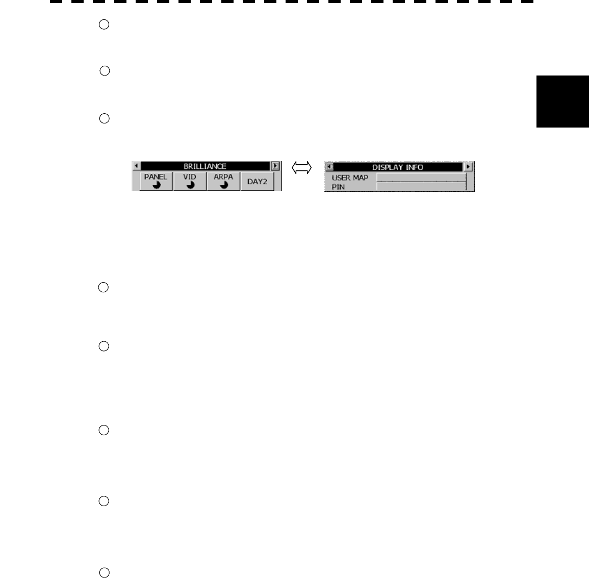
2─14
2
2.2 FUNCTIONS OF SOFTWARE BUTTONS
: TEST menu
Press this button to open the “TEST MENU” screen.
Use this menu screen to operate the self-diagnostic function in the radar.
: DISPLAY screen
Press this button to display optional information such as navigation information.
For the setting of information to be displayed, see section 3.10.4 on page 3-87.
: Selection of display item
The display switches back and forth between the brilliance control screen and the display
information setting screen each time this button is pressed.
DISPLAY INFO
USER MAP: Navigation information readout function
The menu for calling a user-created map opens.
PIN (Personal Information):
Personal code call function
The PIN menu opens. Use this menu to load, save, and delete data.
: PANEL brilliance
Sets the brilliance of operation panel illumination. Five brilliance levels are set each time this
button is pressed.
®See section 3.3.3 on page 3-9.
: VID brilliance
Controls the video level of echoes.
Brilliance changes each time this button is pressed. Four brilliance levels are switched in the
following sequence:
1 ® 2 ® 3 ® 4 ® 1
®See section 3.3.2 on page 3-8.
: ATA brilliance
Controls the brilliance of ATA symbols.
Brilliance changes each time this button is pressed. Five brilliance levels are switched in the
following sequence:
OFF ® 1 ® 2 ® 3 ® 4 ® OFF
: DAY/NIGHT mode
Selects a DAY/NIGHT mode. Brilliance changes according to the selected mode each time this
button is pressed. Four brilliance levels are set in the following sequence:
DAY1 ® DAY2 ® NIGHT1 ® NIGHT2
®See section 3.3.4 on page 3-9.
: ALM ACK (Alarm acknowledgment function)
Press this button to stop the alarm buzzing and the alarm lamp flashing. If more than one alarm
has occurred, the next alarm to be acknowledged is indicated.
The uppercase displays an alarm that can be acknowledged by pressing the key.
The lowercase displays current alarms one by one.
®See section 3.3.7 on page 3-11.
57
58
59
61
60
62
63
64
SECTION 3
BASIC OPERATION
3.1 FLOW OPERATION ......................................................................................3-1
3.1.1 Power ON and Start the System ......................................................3-2
3.1.2 Observe and Adjust Video................................................................ 3-3
3.1.3 Acquire and Measure Data ............................................................... 3-3
3.1.4 End the Operation and Stop the System.........................................3-4
3.2 MENU COMPOSITION..................................................................................3-5
3.2.1 Overview of Menu Structure............................................................. 3-5
3.2.2 Basic Menu Operation ......................................................................3-6
3.3 PREPARATION .............................................................................................3-8
3.3.1 Adjust Display Brilliance .................................................................. 3-8
3.3.2 Adjust Contrast .................................................................................3-8
3.3.3 Adjust Operation Panel Brilliance [PANEL] ....................................3-9
3.3.4 Switch Day/Night Mode [DAY/NIGHT].............................................. 3-9
3.3.5 Adjust Brilliance of Information on Radar Display
(Brilliance Setting) ..........................................................................3-10
3.3.6 Adjust Sound Volume (Buzzer Volume) ........................................ 3-11
3.3.7 Reset Alarm Buzzer [ALARM ACK]................................................ 3-11
3.3.8 Set Display Color ............................................................................3-12
3.4 BASIC OPERATIONS .................................................................................3-15
3.4.1 Start Transmission [TX/PRF].......................................................... 3-15
3.4.2 Stop Transmission [STBY] .............................................................3-15
3.4.3 Change Range (Observation Range Scale) [RANGE+/-]..............3-15
3.4.4 Tune..................................................................................................3-16
3.4.5 Control Sensitivity [GAIN/PL] ........................................................3-16
3.4.6 Suppress Sea Clutter [AUTO-SEA]................................................ 3-17
3.4.7 Suppress Rain/Snow Clutter [AUTO-RAIN]...................................3-19
3.4.8 Reject Radar Interference [IR]........................................................ 3-21
3.4.9 Hide/Display Range Rings (RINGS) ...............................................3-22
3.4.10 Hide Ship’s Heading Line (HL OFF)...............................................3-22
3.4.11 Hide Graphics Information on Radar Display
(Graphic Display) ............................................................................3-23
3.5 GENERAL OPERATIONS ........................................................................... 3-24
3.5.1 Move Cross Cursor Mark by Trackball..........................................3-24
3.5.2 Use EBLs (Electronic Bearing Lines) [EBL1/2].............................3-25
3.5.3 Set EBL Operation (EBL1 /2 Setting)............................................. 3-27
3.5.4 Display Variable Range Markers [VRM1/VRM2]............................3-30
3.5.5 Display Parallel Index Lines (Parallel Index Line) ........................ 3-33
3.5.6 Switch Bearing Display Mode [AZI MODE] ...................................3-41
3.5.7 Switch True/Relative Motion Display Mode [TM/RM] ...................3-42
3.5.8 Move Own Ship’s Display Position [OFF CENT] ..........................3-43
3.5.9 Display Other Ships’ Trails [TRAILS].............................................3-44
3.5.10 Switch Pulse Length (GAIN/PL) .....................................................3-47
3.5.11 Expand Targets (Target Enhance)..................................................3-48
3.5.12 Use Video Process (Process).........................................................3-49
3.5.13 Zoom................................................................................................ 3-50
3.5.14 Use Marker [MOB]........................................................................... 3-51
3.5.15 Marking [MARK].............................................................................. 3-52
3.5.16 Operate EBL Maneuver Function (EBL Maneuver) ...................... 3-53
3.5.17 Operate Multi-Function Control [MULTI]....................................... 3-56
3.5.18 Operate User Key Switches [User Key 1/2] .................................. 3-58
3.5.19 Operation of Guard Zone [ATA Guard Zone] ................................ 3-60
3.5.20 Radar Alarm (Radar Alarm) ............................................................ 3-63
3.6 DISPLAY OWN SHIP’S TRACK ................................................................. 3-67
3.6.1 Display Own Ship’s Track (Display Own Track)........................... 3-67
3.6.2 Set Own Ship’s Track Data Storage Interval
(Own Track Interval) ....................................................................... 3-68
3.6.3 Clear Own Ship’s Track Data (Clear Own Track).......................... 3-69
3.6.4 Cancel Storing of Own Ship’s Track Data
(Own Track Memory) ...................................................................... 3-70
3.7 DISPLAY CHARTS...................................................................................... 3-71
3.7.1 Display Coastline ROM Card Produced by JRC........................... 3-71
3.7.2 Display ERC Card ........................................................................... 3-72
3.7.3 Fill Charts (Fill Land Area) ............................................................. 3-73
3.8 DISPLAY NAVIGATION INFORMATION..................................................... 3-74
3.8.1 Display Waypoint Marks (Waypoint Display)................................ 3-74
3.8.2 Display Navigation Information (NAV Display Setting) ............... 3-75
3.8.3 Create/Edit Navigation Information (Edit User Map).................... 3-76
3.8.4 Set Navigation Information (User Map Setting)............................ 3-82
3.8.5 Set and Display Geodetic System................................................. 3-89
3.9 OPERATE PERFORMANCE MONITOR (PM DISPLAY) ............................ 3-91
3.9.1 Operation Procedures .................................................................... 3-91
3.10 APPLIED OPERATIONS............................................................................. 3-97
3.10.1 Set Radar Signal Processing (Process Setting)........................... 3-97
3.10.2 Set Radar Trails (RADAR Trails Setting)..................................... 3-100
3.10.3 Set Cursor (Cursor Setting) ......................................................... 3-102
3.10.4 Set Screen ..................................................................................... 3-103
3.10.5 Set Scanner (TRX Setting) ........................................................... 3-107
3.10.6 Set Chart Display (Map Setting) .................................................. 3-109
3.10.7 Set LORAN C (LORAN C Correction) .......................................... 3-119
3.11 USE FUNCTION SWITCH [FUNC] ........................................................... 3-120
3.11.1 Operation Procedures .................................................................. 3-120
3.11.2 Function Setting Menu Items....................................................... 3-121
3.11.3 Overview of Function Operations ............................................... 3-122
3.11.4 Overview of Stored Function Setting Data ................................. 3-125
3.11.5 Personal Information (PIN Setting) ............................................. 3-126
3.12 USING CARD............................................................................................ 3-129
3.12.1 Save in and Transfer to Card (MEM CAPA/Copy)....................... 3-129
3.12.2 Erase/Initialize Card Memory (CLR MEM INIT Card).................. 3-133
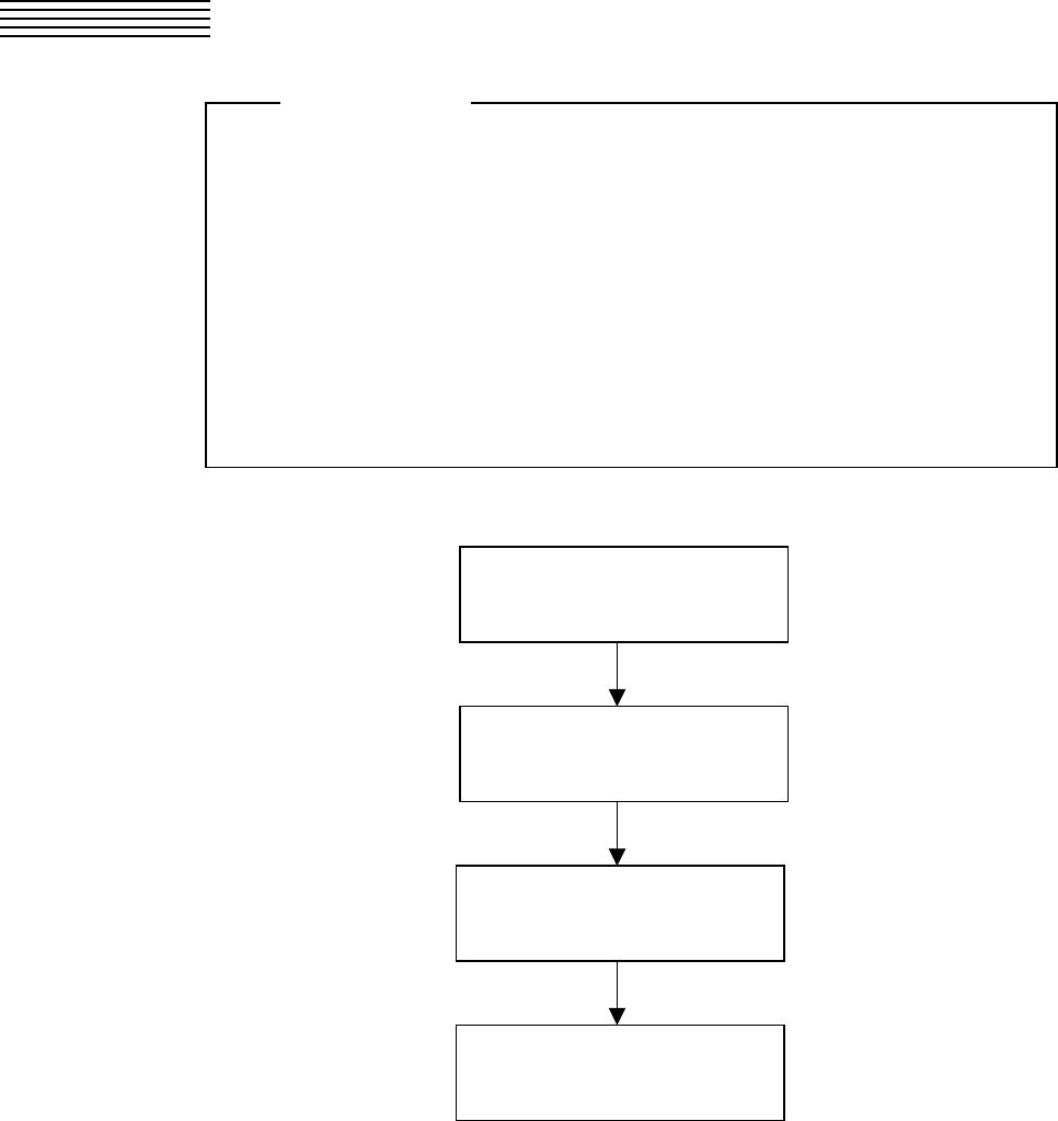
3─1
3.1 FLOW OPERATION
Each operation is described in detail below.
l Do not put anything on the operation panel.
If you put anything hot on it, it may be deformed.
l Do not give any impact to the operation panel,
trackball, or controls.
Otherwise, any failure or damage may result.
Attention
POWER ON AND
START THE SYSTEM
OBSERVE AND
ADJUST VIDEO
ACQUIRE AND
MEASURE DATA
END THE OPERATION AND
STOP THE SYSTEM
3─2
3
3.1 FLOW OPERATION
l Wait for about 2 seconds before turning on the
power again.
l Immediately after the radar is installed, at start of the
system after it has not been used for a long time, or
after the magnetron is replaced, preheat the
equipment in the standby state for 20 to 30 minutes
before setting it into the transmit state.
l If the preheating time is short, the magnetron
causes sparks, resulting in its unstable oscillation.
Start transmission on a short-pulse range and
change the range to the longer pulse ranges in turn.
If the transmission is unstable in the meantime,
immediately place the system back into the standby
state and maintain it in the standby state for 5 to 10
minutes before restarting the operation.
Repeat these steps until the operation is stabilized.
3.1.1 Power ON and Start the System
Attention
A malfunction may occur if the power in the
ship is instantaneously interrupted during
operation of the radar. In this case, the powe
r
should be turned on again.
Caution
3─3
Procedures 1 Check that the ship’s mains are turned on.
2 Press [STBY] key.
The system is turned on, and the preheating time is displayed.
PREHEAT is indicated at the upper left of the radar display.
3 Wait until the preheating time is over.
When the preheating time is over, the preheating time screen disappears, and PREHEAT
at the upper left of the radar display changes to STANDBY .
4 Press [TX/PRF] key.
The radar will start transmission and the antenna will start rotating.
STANDBY at the upper left of the radar display changes to TRANSMIT .
Note: The radar does not start transmission if you press [TX/PRF] key while PREHEAT is
indicated.
3.1.2 Observe and Adjust Video
Procedures 1 Press [RANGE+] key or [RANGE-] key to set the range to the scale
required for target observation.
2 Turn the controls [GAIN], [SEA], and [RAIN] to obtain the clearest
targets.
Refer to
[GAIN]→3-16
[SEA]→3-17
[RAIN]→3-19
for how to use each control.
3.1.3 Acquire and Measure Data
For details on data acquisition and measurement, refer to Section 3.4 “BASIC OPERATIONS” and Section 4
“MEASUREMENT OF RANGE AND BEARING.”
3─4
3
3.1 FLOW OPERATION
3.1.4 End the Operation and Stop the System
Exit 1 Press [STBY] key.
The radar will stop transmission and the antenna will stop rotating.
TRANSMIT at the upper left of the radar display changes to STANDBY .
Maintain the standby state if radar observation is restarted in a relatively short time.
Only pressing the [TX/PRF] key starts observation.
2 Press the [STBY] key and the [TX/PRF] key together.
The system will be turned off.
When conducting maintenance work, make sure to turn
off the power and unplug the power connector J1 of the
processor so that the power supply to the equipment is
completely cut off.
Some equipment components can carry electrical
current even after the power switch is turned off, and
conducting maintenance work without unplugging the
power connector may result in electrocution,
equipment failure, or accidents.
Warning
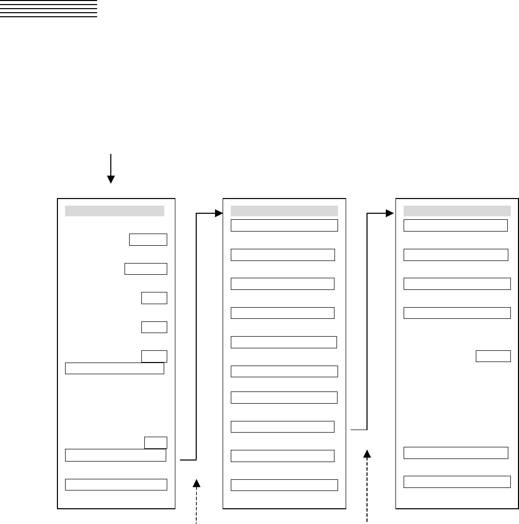
3─5
3.2 MENU COMPOSITION
The Menu system of this radar equipment consists of the main menu and the submenus up to the lower 2 levels.
You can jump to each menu by pressing the menu button at the lower right of the radar display or the switch on
the operation panel.
3.2.1 Overview of Menu Structure
Press [RADAR MENU] key.
Press [RADAR MENU] key or [9]. Press [8].
Use the Main Menu to change the settings of signal processing functions, use the radar menu to change the
settings of other detailed information, and use the Radar Submenus to change the less frequently used settings
or run the system’s self-diagnostic program.
Main Menu
1. IR
IR OFF
2. Process
PROC OFF
3. Target Enhance
OFF
4. Zoom
OFF
5. SART
OFF
6. NAV Information >
7.
8. Graphic Display
ON
9. Radar Menu(→Plot) >
0. EXIT
RADAR Menu
1. Process Setting >
2. RADAR Trails Setting >
3. Marker Setting >
4. Screen Setting >
5. TRX Setting >
6. Inter Switch Setting >
7. NAV Equipment Setting>
8. RADAR Sub Menu >
9. Plot Menu >
0. EXIT
RADAR Sub Menu
1. PIN Setting >
2. Multi Dial Setting >
3. User Key Setting >
4. Date/Time Setting >
5. Buzzer Volume
LEVEL3
9. Test Menu >
0. EXIT
3─6
3
3.2 MENU COMPOSITION
3.2.2 Basic Menu Operation
To open the menu:
Press [RADAR MENU] key.
To close the menu:
Press [RADAR MENU] key.
Alternatively, hold down [0] key until the menu closes.
* Button 54 on the radar display on page 2-7 is also available to switch between ON and OFF.
To move to a lower level of the menu:
The menu is in hierarchical structure. Press the numeric keys [1]-[9] corresponding to the desired
menu item number. Control will move to the lower level.
Alternatively, place the cursor over the item and then press [ENT] key.
> is shown at the right end of a menu item having a lower level.
To move to a higher level of the menu:
Press [0] key while the menu is open. Control will return to the higher level from the lower level.
Alternatively, place the cursor over the 0.EXIT item and then press [ENT] key.
To determine an item:
Press the numeric keys [1]-[9] corresponding to the desired item number. The selected item will be
displayed. Alternatively, place the cursor over the item you want to change, and then press [ENT]
key.
To determine the selected item:
Press the numeric keys [1]-[9] corresponding to the selected item number. Alternatively, place the
cursor over the selected item and then press [ENT] key. If you do not change the setting of the
selected item, press [CLR/INFO] key.
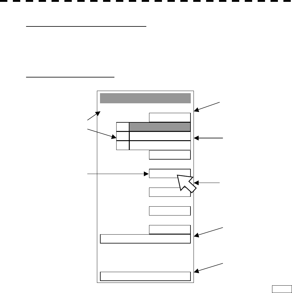
3─7
Menu Operation with the Trackball
The menu items are software buttons that can be operated with the trackball.
An item can be selected by pointing the trackball cursor to the item and pressing [ENT] key, instead
of using the numeric key.
Example of menu display
Process Settin
g
1. Video Latitude
NORMAL
2. VD Noise Re
j
ection
LOW
3. Auto DR Control
ON
4. Process Switch
OFF
5. 2nd Process Mode
REMAIN
6.Process Switch Ran
g
e
6.2nm
7. Fast Tar
g
et Detection
OFF
8. User Function Settin
g
>
0. EXIT
NORMAL1.
WIDE2.
NARROW3.
Item number
Software button
The selected item is
displayed by pressing the
corresponding numeric
key.
An item can be selected by
p
ressing the corresponding
numeric key.
An item can also be
selected by the trackball
and by pressing [ENT]
ke
y
.
An item can also be
selected by pointing the
trackball cursor to the item
and pressing [ENT] key.
Press [8] key to move to
the lower level.
Movement to the lower
level can also be done by
pointing the trackball
cursor to the item and
p
ressing [ENT] key.
Press [0] key move to the
higher level. Movement
to the higher level can also
be done by pointing the
trackball cursor to 0.EXIT
and pressing [ENT] key.
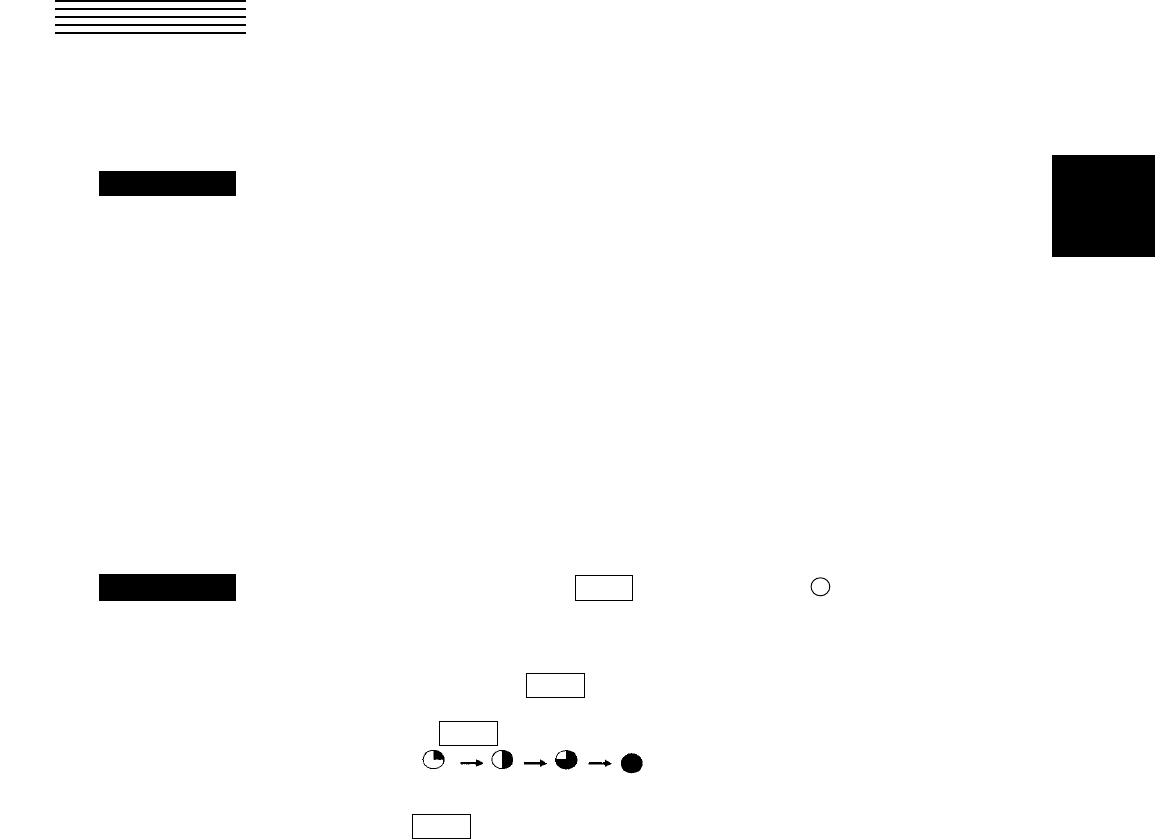
3─8
3
3.3 PREPARATION
3.3.1 Adjust Display Brilliance
Procedures 1 Obtain the best-to-see display with optimum brilliance by turning the
[BRILL] control at the lower right of the display unit.
Turning the [BRILL] control clockwise increases the brilliance of the entire display.
Conversely, turning the [BRILL] control counterclockwise decreases the brilliance of the
entire display.
In consideration of the ambient brightness, adjust display brilliance that is high enough to
easily observe the radar display but does not glare.
3.3.2 Adjust Contrast
Adjust the contrast of the radar video display.
Procedures 1 Point the trackball to the VID button (* Button 61 on the radar display
on page 2-7) at the lower right of the radar display, press [ENT] key, and
then make adjustment to obtain the best-to-see video.
Point the trackball to the VID button at the lower right of the radar display and then
press [ENT] key to adjust the contrast of the radar video display at four levels.
Each time the VID button is clicked, the contrast level changes in the following
sequence:
Adjust the VID button to obtain the best-to-see video with optimum contrast.

3─9
3.3.3 Adjust Operation Panel Brilliance [PANEL]
Procedures 1 Press [PANEL] key to adjust the brilliance of the operation panel light.
There are five brilliance levels, and brilliance increases by one level each time the
[PANEL] key is pressed. When it reaches the highest level, it is resumed to the lowest
level.
In consideration of the ambient brightness, adjust panel brilliance that is high enough to
read the characters on the operation panel but does not glare.
The [PANEL] key lamp lights up irrespective of panel brilliance adjustment.
* Button 60 on the radar display on page 2-7 is also available for switching.
3.3.4 Switch Day/Night Mode [DAY/NIGHT]
The day/night mode changes in the following sequence each time the [DAY/NIGHT] key is pressed:
DAY1 ® DAY2 ® NIGHT1 ® NIGHT2
The current mode is indicated at the lower right of the radar display.
The brilliance level in accordance with the selected mode is saved. For brilliance adjustment, refer to page
next page. For day/night mode switching, refer to 3-12page Section 3.3.8 “Set Display Color.”
* Button 63 on the radar display on page 2-7 is also available for switching.
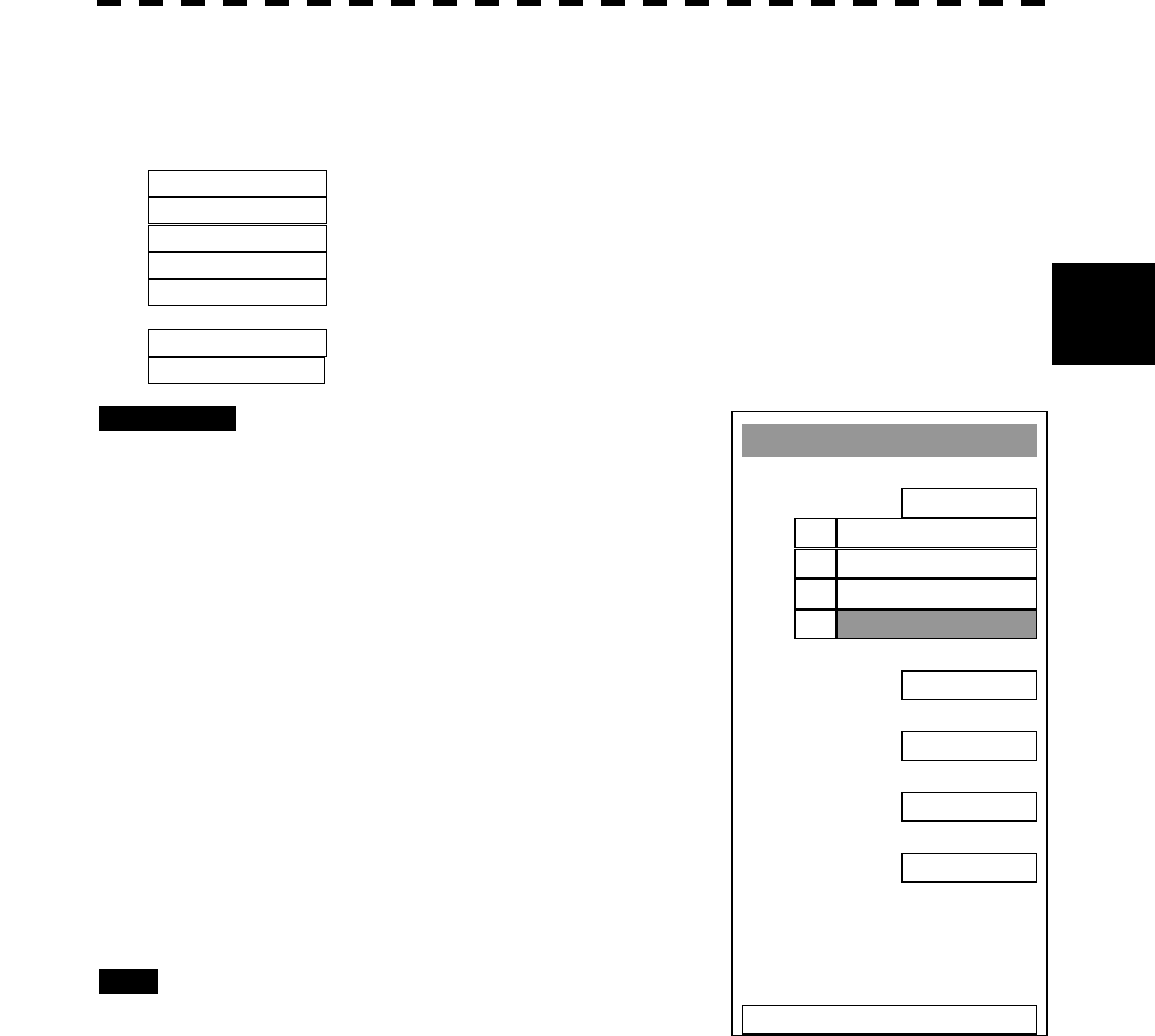
3─10
3
3.3 PREPARATION
Brilliance Settin
g
1. RADAR Video
LEVEL4
2. RADAR Trails
LEVEL4
3. ATA/AIS
LEVEL3
4. Fix Marker
LEVEL2
5. EBL
/
VRM
LEVEL2
6. Character
LEVEL4
7. Panel
LEVEL4
0. EXIT
LEVEL11.
LEVEL22.
LEVEL33.
LEVEL44.
3.3.5 Adjust Brilliance of Information on Radar Display
(Brilliance Setting)
Brilliance can be adjusted for each item of information on the radar display by operating the menu.
RADAR Video Adjusts the brilliance of radar echoes.
RADAR Trails Adjusts the brilliance of radar trails.
ATA/AIS Adjusts the brilliance of ATA symbols and AIS symbols.
FIX Marker Adjusts the brilliance of fixed range markers.
EBL/VRM Adjusts the brilliance of variable range markers (VRM1 and VRM2) and
electronic bearing lines (EBL1 and EBL2).
Character Adjusts the brilliance of characters.
Panel Adjusts the brilliance of operation panel.
Procedures 1 Press [RADAR MENU] key twice.
Press [4] key.
Press [2] key.
The Brilliance Setting Menu will appear.
2 Select the item for which brilliance is
to be adjusted, pressing the numeric
keys [1] to [7].
The pull-down menu will appear showing the
brilliance levels.
3 Select the brilliance level number to be
set, pressing the numeric key.
The selected brilliance level will be set.
To change the setting of another item, repeat
steps 2 and 3.
Exit 1 Press [RADAR MENU] key.
The menu will be closed.
Note: The brilliance levels set here are saved in accordance with the day/night mode.
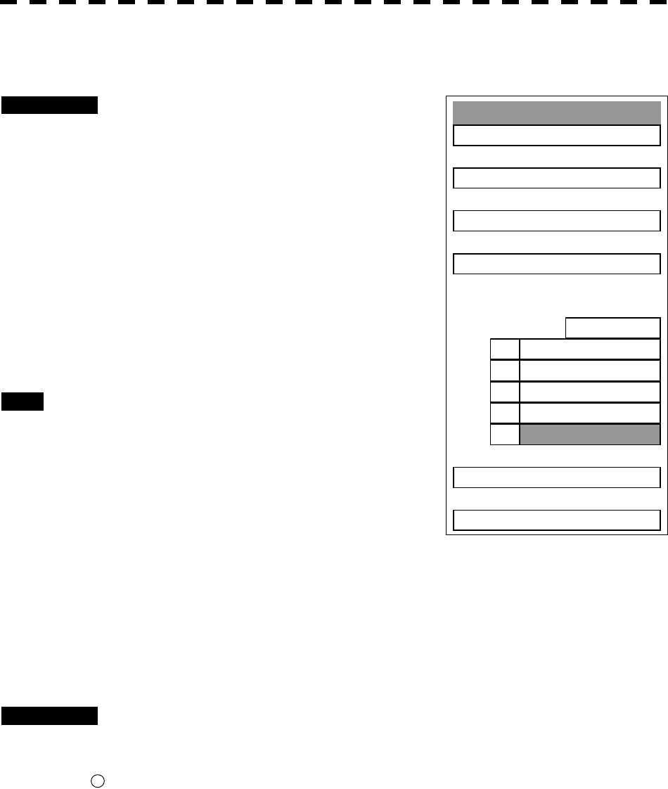
3─11
3.3.6 Adjust Sound Volume (Buzzer Volume)
Procedures 1 Press [RADAR MENU] key twice.
Press [8] key.
The RADAR Sub Menu will appear.
2 Press [5] key to select Buzzer Volume.
The pull-down menu will appear showing the
volume levels.
3 Select the volume level number to be
set, pressing the numeric keys [1] to
[5].
The selected volume level will be set.
Exit 1 Press [RADAR MENU] key.
The menu will be closed.
3.3.7 Reset Alarm Buzzer [ALARM ACK]
When an audible alarm is issued, use ALARM ACK to acknowledge the alarm information, stop the alarm
buzzing, and stop the alarm lamp flashing. (If more than one alarm has occurred, press the switch for each
alarm indication.) The alarm stops buzzing, but the alarm indication does not disappear.
Procedures 1 Press [ALARM ACK] key.
The alarm will stop buzzing.
* Button 64 on the radar display on page 2-7 is also available to stop buzzing the alarm.
RADAR Sub Menu
1. PIN Settin
g
2. Multi Dial Settin
g
3. User Key Settin
g
4. Date/Time Settin
g
5. Buzzer Volume
LEVEL4
9. Test Menu
0. EXIT
LEVEL4
1. OFF
5.
2. LEVEL1
3. LEVEL2
4. LEVEL3
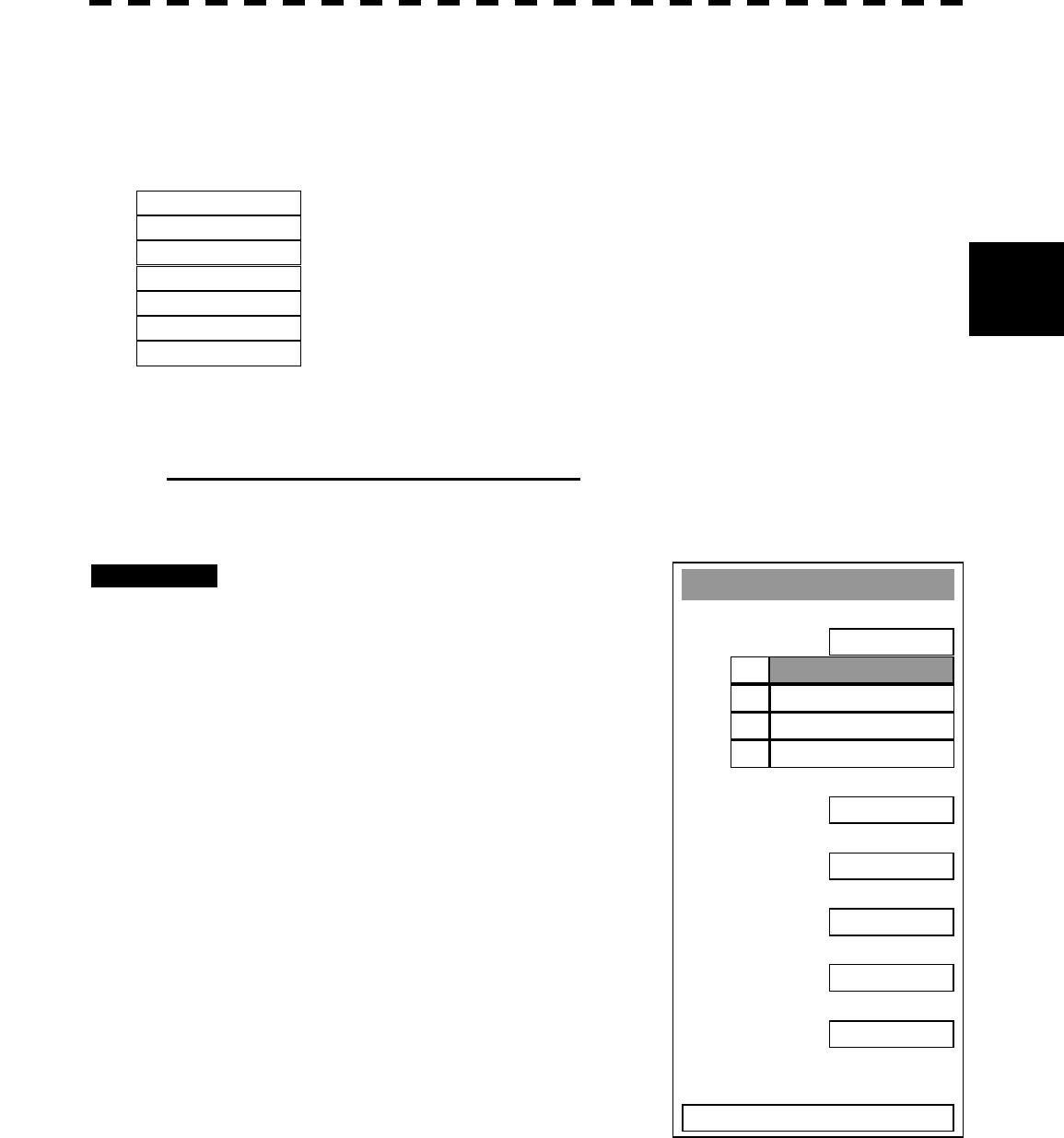
3─12
3
3.3 PREPARATION
3.3.8 Set Display Color
For each day/night mode, set the colors of the background outside the bearing scale, the background inside the
bearing scale, characters, radar echoes, and radar trails.
Color Adjustment by Menu Operation
Day/Night Registers the switching of a day/night mode.
Color Scheme Calls a preset color scheme pattern.
Outer PPI Adjusts the background color outside the bearing scale.
Inner PPI Adjusts the background color inside the bearing scale.
Character Adjusts the colors of characters and bearing scales.
RADAR Echo Adjusts the colors of radar echoes.
RADAR Trails Adjusts the colors of radar trails.
Time: Display interval time is selected.
Cont: Continuous display
Selecting a Day/Night Mode (Day/Night)
Select the mode for which color setting is to be changed.
Procedures 1 Press [RADAR MENU] key twice.
Press [4] key.
Press [1] key.
The Display Color Setting Menu will appear.
2 Press [1] key.
The Day/Night mode selection screen will
appear.
3 Select the mode number for color
adjustment, pressing the numeric keys
[1] to [4].
The mode will be selected.
Display Color Settin
g
1. Day/Ni
g
ht
DAY1
2. Color Scheme
ORIGINAL
3. Outer PPI
GRAY
4. Inner PPI
BLAC
K
5. Character
WHITE
6. RADAR Echo
YELLOW
7. RADAR Trails ( Time )
CYAN
8. RADAR Trails ( Cont )
WHITE
0. EXIT
DAY11.
DAY22.
NIGHT13.
NIGHT24.
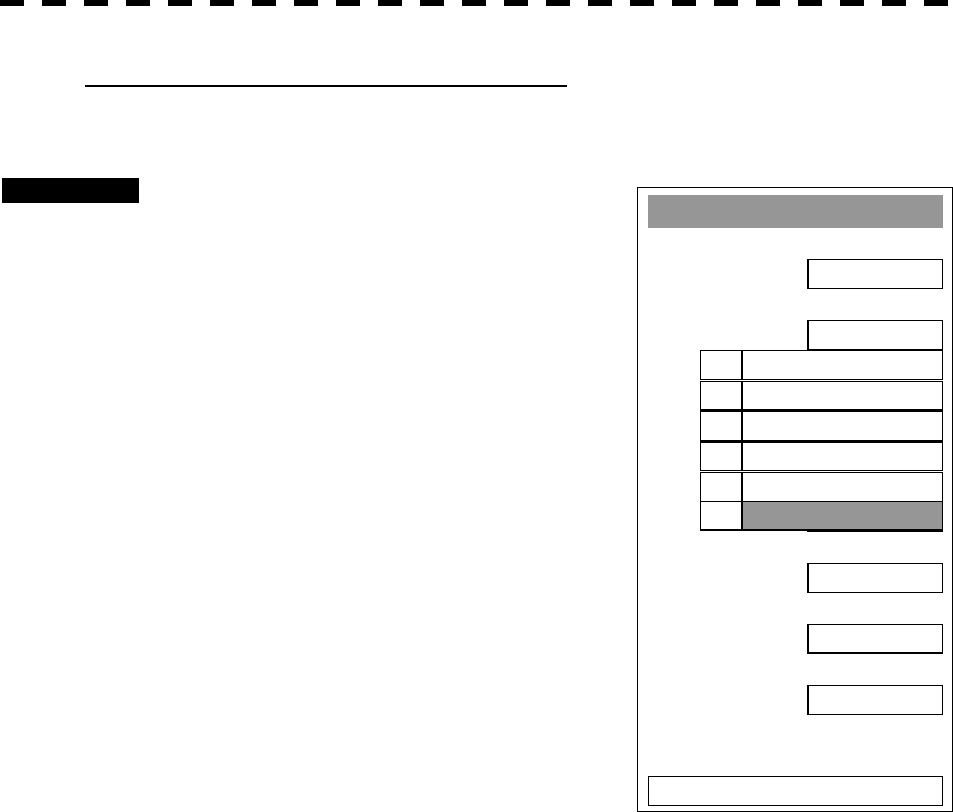
3─13
Calling of a Color Scheme (Color Scheme)
Call a preset color scheme pattern.
Procedures 1 Press [2] key while the Display Color
Setting Menu is open.
The Color Scheme Menu will appear.
2 Select the pattern number to be set,
pressing the numeric keys [1] to [6].
The selected color scheme pattern will be set.
Display Color Settin
g
1. Day/Ni
g
ht
DAY1
2. Color Scheme
ORIGINAL
3. Outer PPI
GRAY
4. Inner PPI
BLAC
K
5. Character
WHITE
6. RADAR Echo
YELLOW
7. RADAR Trails ( Time )
CYAN
8. RADAR Trails ( Cont )
WHITE
0. EXIT
STANDARD
1.
FLASHY2.
PLANE3.
70
’
s4.
SAFARI5.
ORIGINAL6.
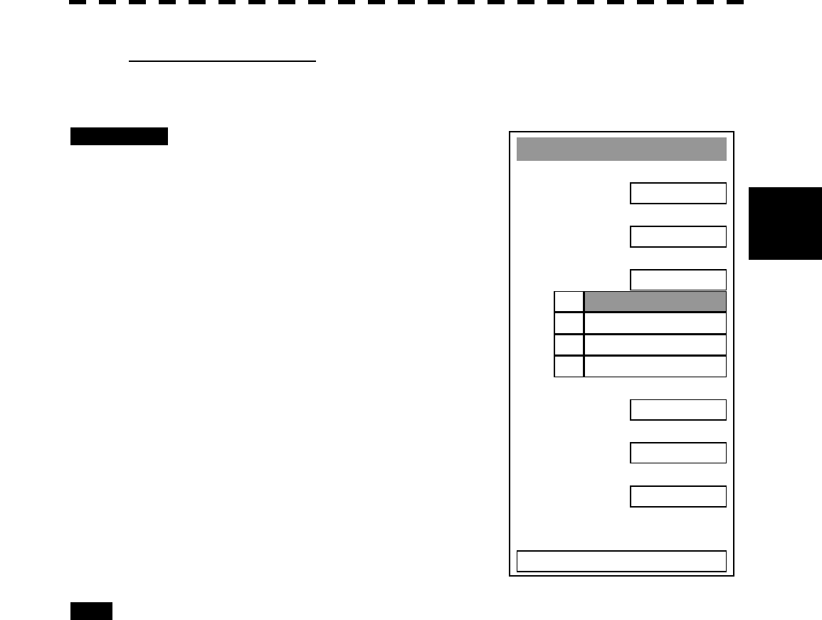
3─14
3
3.3 PREPARATION
Setting Colors of Items
Set the display color of each item.
Procedures 1 While the Display Color Setting Menu
is open, select the item number for
color setting, pressing the numeric
keys [3] to [8].
The color selection screen will appear.
3. Outer PPI: Adjusts the background color outside the
bearing scale.
4. Inner PPI: Adjusts the background color inside the
bearing scale.
5. Character: Adjusts the colors of characters and
bearing scales.
6. RADAR Echo: Adjusts the colors of radar echoes.
7. 8. RADAR Trails: Adjusts the colors of radar trails.
Time: Display interval time is selected.
Cont: Continuous display
2 Select the color number to be set,
pressing the numeric key.
The selected color will be set.
To set more than one color, repeat steps 1
and 2.
Exit 1 Press [RADAR MENU] key.
The menu will be closed.
Display Color Settin
g
1. Day /Ni
g
ht
DAY1
2. Color Scheme
ORIGINAL
3. Outer PPI
GRAY
4. Inner PPI
BLAC
K
5. Character
WHITE
6. RADAR Echo
YELLOW
7. RAD
A
R Trails ( Time )
CYAN
8. RADAR Trails ( Cont )
WHITE
0. EXIT
1.
BLUE2.
DARK BLUE3.
BLAC
K
4.
GRAY
3─15
3.4 BASIC OPERATIONS
3.4.1 Start Transmission [TX/PRF]
Procedures 1 Press [TX/PRF] key.
The radar will start transmission and the antenna will start rotating.
The indication STANDBY at the upper left of the radar display changes to
TRANSMIT .
Note: The radar does not start transmission if you press [TX/PRF] key while PREHEAT is
indicated.
3.4.2 Stop Transmission [STBY]
Procedures 1 Press [STBY] key.
The radar will stop transmission and the antenna will stop rotating.
The indication TRANSMIT at the upper left of the radar display changes to
STANDBY .
* Button 6 on the radar display on page 2-7 is also available to start/stop transmission.
3.4.3 Change Range (Observation Range Scale) [RANGE+/-]
Procedures 1 Press [RANGE+] key or [RANGE-] key to set the range to the scale
required for target observation.
To observe long-range targets, press [RANGE+] key.
To zoom and observe a short-range target near the own ship, press [RANGE-] key.
* Button 1 on the radar display on page 2-7 is also available to switch the range.

3─16
3
3.4 BASIC OPERATIONS
3.4.4 Tune
This system tunes the transmitting frequency and receiving frequency under automatic control, so it does not
need any tuning by hand
3.4.5 Control Sensitivity [GAIN/PL]
Procedures 1 Control noise on the radar display by turning the [GAIN/PL] control until
targets can be easily observed.
Turning [GAIN/PL] control clockwise increases sensitivity.
Turning [GAIN/PL] control counterclockwise decreases sensitivity.
Turning the [GAIN/PL] control clockwise increases receiving sensitivity and extends the
radar observation range. If the sensitivity is too high, the receiver noise increases reducing
the contrast between the targets and the background video. As a result, the targets become
obscure on the radar display.
To observe densely crowded targets or short-range targets, turn the [GAIN/PL] control
counterclockwise to reduce the sensitivity so that the targets are easy to observe. However,
be careful not to overlook important small targets.
3─17
3.4.6 Suppress Sea Clutter [AUTO-SEA]
Procedures 1 Control the sea clutter returns on the radar display by turning the
[AUTO-SEA] control until targets can be easily observed.
Turning [AUTO-SEA] control clockwise suppresses sea clutter returns.
Turning [AUTO-SEA] control counterclockwise intensifies sea clutter returns.
The sea clutter suppression function suppresses sea clutter returns by decreasing the receiving
sensitivity on a short range.
Turning the [AUTO-SEA] control clockwise heightens the effect of sea clutter suppression.
However, be careful that excessive suppression causes low signal-strength targets such as
buoys and boats to disappear from the radar display.
Before sea clutter returns can be suppressed in accordance with their intensity, the automatic
sea clutter suppression mode must be selected by pressing the [AUTO-SEA] control. Use
this automatic mode when sea clutter returns vary in direction.
To change back to the manual mode, press the [AUTO-SEA] control again.
Note: The AUTO SEA (automatic sea clutter suppression) mode and the AUTO RAIN (automatic
rain/snow clutter suppression) mode cannot be used at the same time.
Using AUTO SEA (automatic sea clutter suppression function)
Procedures 1 Press the [AUTO-SEA] control.
AUTO SEA is selected, and SEA AUTO is indicated at the lower left of the radar
display. If AUTO SEA is selected, rotating the AUTO RAIN control and AUTO SEA
control can make fine adjustments manually.
When using the [AUTO SEA] function, never set the
suppression level too high canceling out all image
noises from the sea surface at close range.
Detection of not only echoes from waves but also
targets such as other ships or dangerous objects will
become inhibited.
When using the [AUTO SEA] function, make sure to
choose the most appropriate image noise suppression
level.
Caution

3─18
3
3.4 BASIC OPERATIONS
Note: When AUTO SEA is selected, AUTO RAIN is switched to the manual mode.
AUTO SEA and AUTO RAIN cannot be selected at the same time.
Cancellation 1 Press the [AUTO-SEA] control.
AUTO SEA is deselected, SEA AUTO at the lower left of the radar display changes to
SEA MAN , and AUTO SEA is cancelled.
* Button 14 on the radar display on page 2-7 is also available to switch AUTO/MANUAL.
3─19
3.4.7 Suppress Rain/Snow Clutter [AUTO-RAIN]
Procedures 1 Control the rain/snow clutter returns on the radar display by turning the
[AUTO-RAIN] control until targets can be easily observed.
Turning [AUTO-RAIN] control clockwise suppresses rain/snow clutter returns.
Turning [AUTO-RAIN] control counterclockwise intensifies rain/snow clutter returns.
When the [AUTO-RAIN] control is turned clockwise, the rain/snow clutter suppression
function suppresses rain/snow clutter returns and gets targets hidden by rain/snow clutter
returns to appear on the radar display. However, be careful that excessive suppression may
cause small targets to be overlooked. Since the rain/snow clutter suppression function also
has the effect of suppressing sea clutter, the suppression efficiency improves when the
[AUTO-RAIN] control is used with the [AUTO-SEA] control. In general, turn the
[AUTO-RAIN] control fully to the left.
Before rain/snow clutter returns can be suppressed in accordance with their intensity, the
automatic rain/snow clutter suppression mode must be selected by pressing the
[AUTO-RAIN] control.
To change back to the manual mode, press the [AUTO-RAIN] control again.
Note: The AUTO SEA (automatic sea clutter suppression) mode and the AUTO RAIN (automatic
rain/snow clutter suppression) mode cannot be used at the same time.
Using AUTO RAIN (automatic rain/snow clutter suppression function):
Procedures 1 Press the [AUTO-RAIN] control.
AUTO RAIN is selected, and RAIN AUTO is indicated at the lower left of the radar
display. Rotating the AUTO RAIN control and AUTO SEA control can make fine
adjustments manually.
When using the [AUTO RAIN] function, never set the
suppression level too high canceling out all image
noises from the rain or snow at the close range.
Detection of not only echoes from the rain or snow bu
t
also targets such as other ships or dangerous objects
will become inhibited.
When using the [AUTO RAIN] function, make sure to
choose the most appropriate image noise suppression
level.
Caution

3─20
3
3.4 BASIC OPERATIONS
Note: When AUTO RAIN is selected, AUTO SEA is switched to the manual mode.
AUTO SEA and AUTO RAIN cannot be selected at the same time.
Cancellation 1 Press the [AUTO-RAIN] control.
AUTO RAIN is deselected, RAIN AUTO at the lower left of the radar display
changes to RAIN MAN , and AUTO RAIN is cancelled.
* Button 15 on the radar display on page 2-7 is also available to switch AUTO/MANUAL.
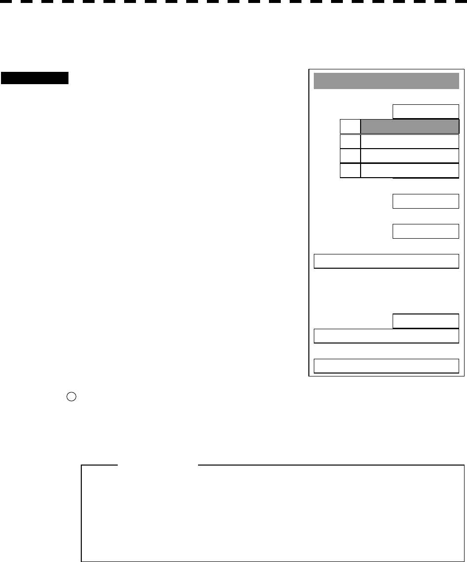
3─21
3.4.8 Reject Radar Interference [IR]
Procedures 1 Press [RADAR MENU] key.
The Main Menu will appear.
2 Press [1] key.
The IR Menu will appear.
3 Select the level number to be set,
pressing the numeric keys [1] to [4].
The selected level will be set.
Rejection levels of the interference rejector
IR OFF: Interference rejector off
IR LOW: Interference rejection level - low
IR MEDIUM: Interference rejection level -
moderate
IR HIGH: Interference rejection level - high
When a high interference rejection level is selected,
the radar’s ability of detecting small targets such as
buoys and small boats lowers.
In general, [IR LOW] should be selected.
* Button 10 on the radar display on page 2-7 is also available to switch IR settings.
l When viewing a radar beacon or SART signal, select
IR OFF (Interference Rejector OFF) because IR
processing suppresses the video.
Attention
Main Menu
1. I
R
IR OFF
2. PROCES
PROC OFF
3. TARGET ENHANCE
OFF
4. Zoom
OFF
5. SART
OFF
6. NAV Information
7.
8. Graphic Display
ON
9. RADAR Menu (Plot)
0. EXIT
IR OFF1.
IR LOW2.
IR MEDIUM3.
IR HIGH4.

3─22
3
3.4 BASIC OPERATIONS
3.4.9 Hide/Display Range Rings (RINGS)
Procedures 1 Press [RR/HL] key.
The range rings display switches back and forth between display and non-display each
time [RR/HL] key is pressed.
Refer to page 3-10 for how to change the brilliance of range rings.
* Button 2 on the radar display on page 2-7 is also available to switch between ON and OFF.
3.4.10 Hide Ship’s Heading Line (HL OFF)
Procedures 1 Hold down [RR/HL] key.
The ship’s heading line is hidden while [RR/HL] key is held down.
The ship’s heading line (HL) that presents the course of own ship is always shown on the radar
display. The heading line is hidden while [RR/HL] key is held down, so the targets on the
heading line can be easily observed.
* Button 22 on the radar display on page 2-7 is also available to switch between ON and OFF.
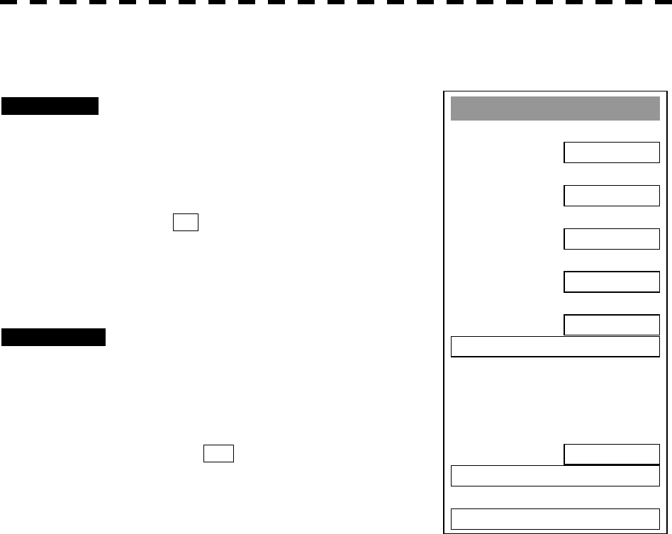
3─23
Main Menu
1. I
R
IR OFF
2. Process
PROC OFF
3. Tar
g
et Enhance
OFF
4. Tar
g
et Enhance
OFF
5. SART
OFF
6. NAV Information
7.
8. Graphic Display
ON
9. RADAR Menu ( Plot )
0. EXIT
3.4.11 Hide Graphics Information on Radar Display (Graphic Display)
Procedures 1 Press [RADAR MENU] key.
The Main Menu will appear.
2 Press [8] key.
The setting of Graphic Display will be changed
to ON .
Graphics information other than VRMs, EBLs, HL,
cross cursor mark, and range rings on the radar
display is temporarily hidden.
Cancellation 1 Press [RADAR MENU] key.
The Main Menu will appear.
2 Press [8] key.
The setting of Graphic Display will be changed
back to OFF .
Temporarily hidden graphics information is
displayed again.
Various graphics information such as ATA/AIS symbols, NAV lines, and MAP information is
shown on the radar display of this system, and may make it difficult to view the radar video.
In this case, use this function to temporarily hide unnecessary graphics information.
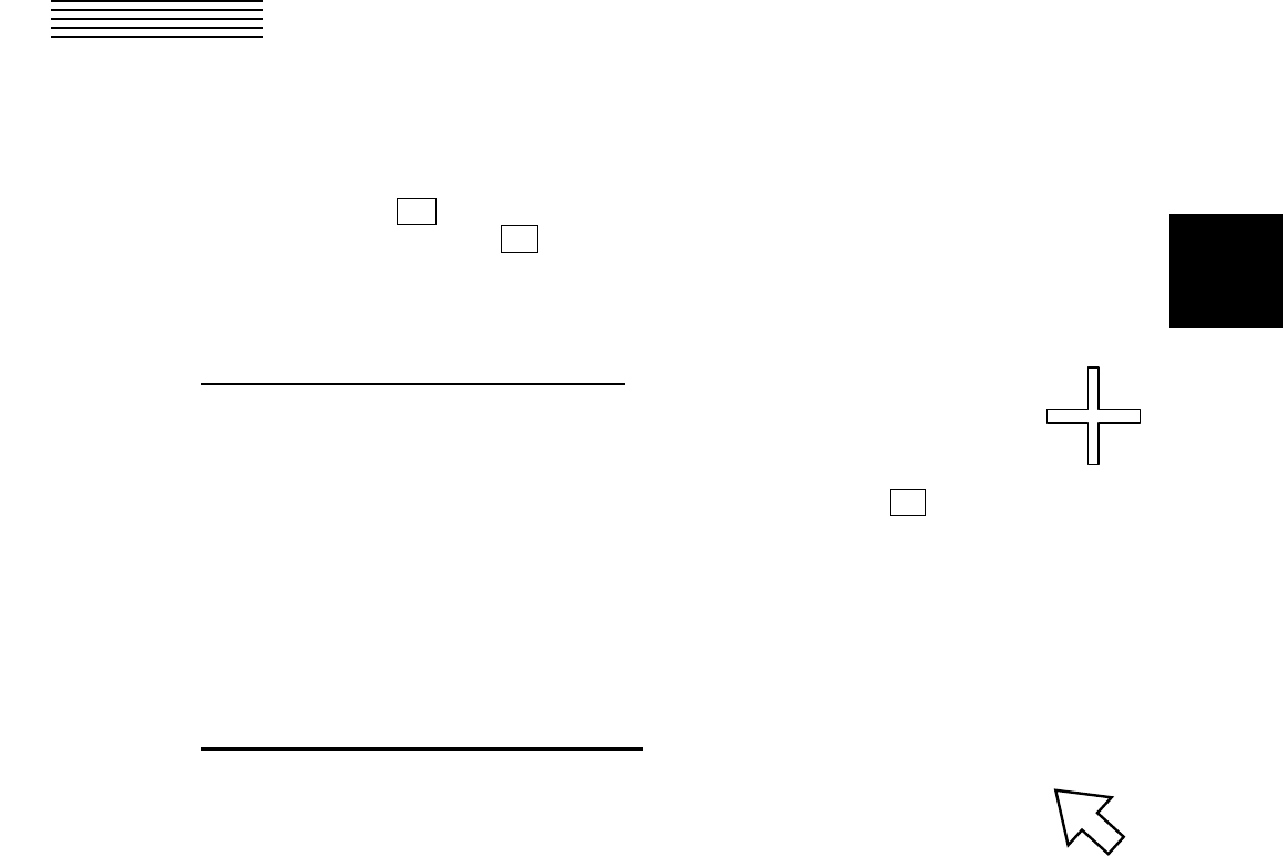
3─24
3
3.5 GENERAL OPERATIONS
3.5.1 Move Cross Cursor Mark by Trackball
The cross cursor mark + is used for position designation and other purposes in various operating
procedures. The cross cursor mark + moves in coupling with the trackball. If the trackball is rotated up
and down or right and left, the cross cursor mark follows the move of the trackball.
Operators must be familiar with trackball operation before running the system.
Operation inside Radar Video PPI
The cross cursor mark as shown at right is displayed inside the radar video PPI.
1) The distance and bearing between own ship and the cross cursor mark + , and the degrees of
latitude and longitude are digitally indicated at the upper right of the radar display.
2) When moving the current center position, use the cross cursor mark to designate a new center
position.
3) Use the cross cursor mark to create marks and lines.
4) When the ATA function is installed as an option, use the cross cursor mark to acquire targets in
manual mode.
Operation outside Radar Video PPI
As shown at right, the cursor mark changes into the pointer
outside the radar video PPI.
1) Use the pointer to operate software buttons.
2) Use the pointer to select menu items.
* The EBL/VRL dial is available for operating the cursor mark. Pressing the EBL dial for two seconds can
perform switching to the trackball operation. For details, refer to Page 3-102.

3─25
3.5.2 Use EBLs (Electronic Bearing Lines) [EBL1/2]
EBLs (Electronic Bearing Lines) are indispensable to the measurement of bearings.
Operators must be familiar with the operation of EBLs beforehand.
EBL1 Operation
If EBL2 is selected or EBL1 is not displayed, press [EBL1] key to select EBL1 before starting operation.
(The currently selected EBL is shown in reverse video at the lower right of the radar display.)
Procedures 1 Press [EBL1] key.
EBL1 at the lower right of the radar display will be shown in reverse video, and EBL1
becomes operable.
2 Press [EBL1] key again.
The EBL1 display will disappear.
* Button 31 on the radar display on page 2-7 is also available to switch EBL1 between ON and OFF.
EBL2 Operation
If EBL1 is selected or EBL2 is not displayed, press [EBL2] key to select EBL2 before starting operation.
(The currently selected EBL is shown in reverse video at the lower right of the radar display.)
Procedures 1 Press [EBL2] key.
EBL2 at the lower right of the radar display will be shown in reverse video, and EBL2
becomes operable.
2 Press [EBL2] key again.
The EBL2 display will disappear.
* Button 32 on the radar display on page 2-7 is also available to switch EBL1 between ON and OFF.
Operation procedures are described on the following pages. For how to measure distance and
bearing, see Section 4.
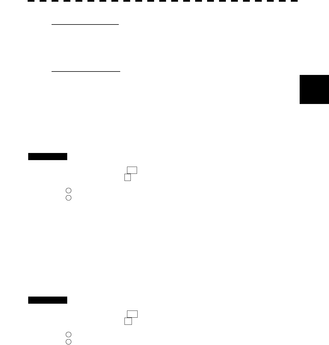
3─26
3
3.5 BASIC OPERATIONS
EBL Bearing Display
The bearing values of EBL1 and EBL2 currently displayed on the PPI are indicated at the lower right of
the radar display.
The currently operable EBL1 or EBL2 is shown in reverse video beside the bearing value.
Starting Point of EBL
The starting point of the currently operating EBL can be switched from the center of the radar display
(CENTER) to any offset position (OFFSET).
Note: The offset position of the EBL’s starting point can be fixed on the radar display or at specific
latitude and longitude. (For details, refer to page 3-28.)
[I] Offsetting the starting point of EBL1 while EBL1 is operating:
Procedures 1 Press the [EBL] control.
The indication C to the right of the EBL value at the lower right of the radar display
will change to O , and “OFFSET” will be set.
* Button 35 on the radar display on page 2-7 is also available to switch the offset of EBL1.
* Button 36 on the radar display on page 2-7 is also available to switch the offset of EBL2.
2 Move the starting point of EBL1 with the trackball.
3 Press [ENT] key at the starting point of EBL1 you want to move.
The starting point of EBL1 will be determined.
If EBL2 is operating, the starting point of EBL2 is offset.
[II] Moving the starting point of EBL1 to the own ship’s position while EBL1 is
operating:
Procedures 1 Press the [EBL] control twice.
The indication O to the right of the EBL value at the lower right of the radar display
will change to C , and “CENTER” will be set.
* Button 35 on the radar display on page 2-7 is also available to switch EBL1 CENTER.
* Button 36 on the radar display on page 2-7 is also available to switch EBL2 CENTER.
If EBL2 is operating, the starting point of EBL2 moves to the own ship’s position.
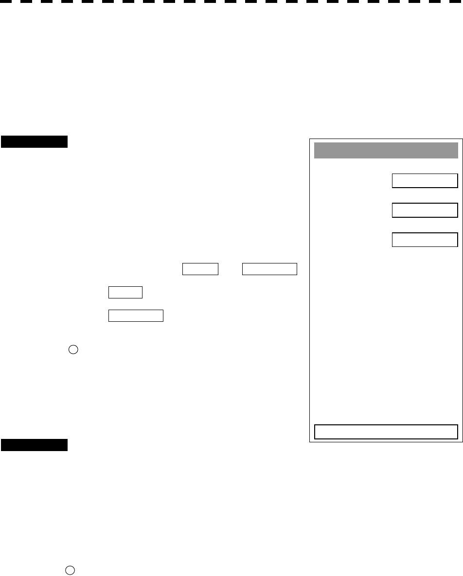
3─27
3.5.3 Set EBL Operation (EBL1 /2 Setting)
[I] Setting the bearing display mode of EBL1 (EBL1 Bearing REF)
Determine whether to display EBLs (Electronic Bearing Lines) in true bearing mode or relative bearing
mode.
Procedures 1 Press [RADAR MENU] key twice.
Press [3] key
Press [1] key.
The EBL1 Setting Menu will appear.
2 Press [1] key.
The setting of EBL1 Bearing REF will be
switched between TRUE and RELATIVE .
TRUE : EBL1 is displayed in true
bearing mode.
RELATIVE : EBL2 is displayed in relative
bearing mode.
* Button 39 on the radar display on page 2-7 is also available to
switch the display mode of EBL1.
[II] Setting the bearing display mode of EBL2
(EBL2 Bearing REF)
Procedures 1 Press [RADAR MENU] key twice.
Press [3] key.
Press [2] key.
The EBL2 Setting Menu will appear.
Subsequently, set the bearing display mode of EBL2 performing the same operation as
explained in [I].
* Button 40 on the radar display on page 2-7 is also available to switch the display mode of EBL2.
EBL1 Settin
g
1. EBL1 Bearin
g
REF
TRUE
2. EBL1 Floatin
g
OFF
3. EBL1 Bearin
g
Fix
SCREEN
0. EXIT
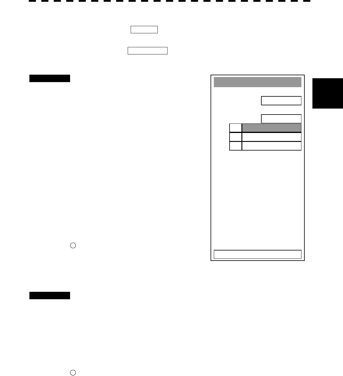
3─28
3
3.5 BASIC OPERATIONS
[III] Setting the mode to move the starting point of EBL1 (EBL1 Floating)
When this function is set to L/L FIX and the starting point of an EBL is moved to a position, the
starting point can be fixed at the latitude and longitude of that position. The function is effective when
the bearing from a certain point is repeatedly measured.
When the function is set to SCREEN FIX , the starting point of an EBL is fixed on the radar display.
The starting point is always indicated at the same position on the radar display even when the own ship
has moved.
Procedures 1 Press [RADAR MENU] key twice.
Press [3] key
Press [1] key.
The EBL1 Setting Menu will appear.
2 Press [2] key.
The EBL1 Floating Setting Menu will appear.
3 Select the mode number to be set,
pressing the numeric keys [1] to [3].
The selected mode will be set.
OFF: Floating mode off
SCREEN FIX: The starting point of EBL1 is
fixed on the radar display.
L/L FIX: The starting point of EBL1 is
fixed at specific latitude and
longitude.
* Button 35 on the radar display on page 2-7 is also available to
switch the Screen Fix and L/L Fix of EBL1.
[IV] Setting the mode to move the starting point of EBL2 (EBL2 Floating)
Procedures 1 Press [RADAR MENU] key twice.
Press [3] key.
Press [2] key.
The EBL2 Setting Menu will appear.
Subsequently, set the EBL2’s starting point move mode performing the same operation as
explained in [III].
* Button 36 on the radar display on page 2-7 is also available to switch the Screen Fix and L/L Fix of EBL2.
Notes: · The course data and the own ship’s latitude and longitude data are required for activating the L/L Fix
mode.
· While the L/L Fix mode is active, the starting point of an EBL will be returned to the center if it
disappears from the radar display when moved.
EBL1 Settin
g
1. EBL1 Bearin
g
REF
TRUE
2. EBL1 Floatin
g
OFF
3. EBL1 Bearin
g
Fix
SCREEN
0. EXIT
OFF1.
SCREEN FI
X
2.
3. L/L FI
X
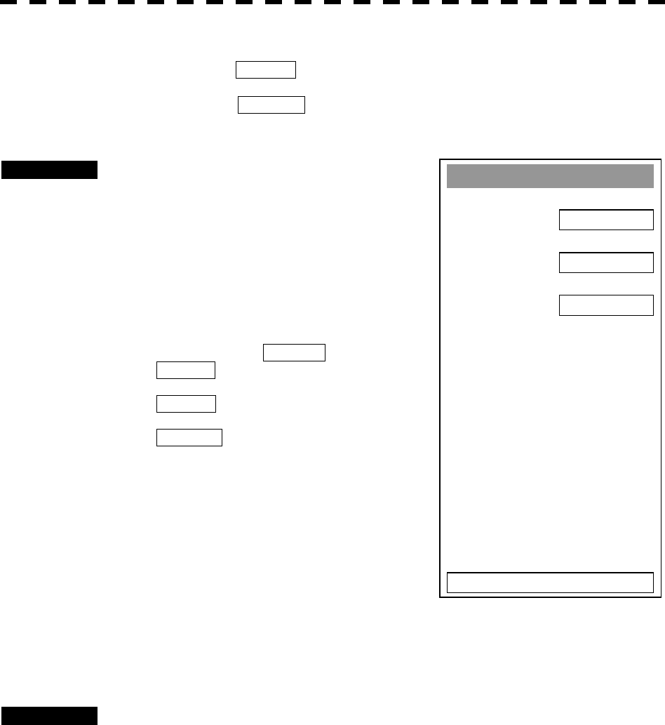
3─29
[V] Setting the EBL1 bearing fix mode (EBL1 Bearing FIX)
While this function is set to ANGLE , an EBL is fixed to the preset bearing. For example, if the true
bearing 020° is preset, the EBL is fixed to the true bearing 020° even when the own ship turns.
While the function is set to SCREEN , the EBL is fixed on the radar display. The starting point is
always indicated at the same position on the radar display even when the own ship has moved.
Procedures 1 Press [RADAR MENU] key twice.
Press [3] key
Press [1] key.
The EBL1 Setting Menu will appear.
2 Press [3] key.
The setting of EBL1 Bearing Fix will be
switched between ANGLE and
SCREEN .
ANGLE : EBL1 bearing is fixed to the
preset value.
SCREEN : EBL1 bearing is fixed on the
radar display.
[VI] Setting the EBL2 bearing fix mode (EBL2 Bearing Fix)
Procedures 1 Press [RADAR MENU] key twice.
Press [3] key.
Press [2] key.
The EBL2 Setting Menu will appear.
Subsequently, set the EBL2 bearing fix mode performing the same operation as explained in
[V].
Note: The course data is required for activating this function.
EBL1 Settin
g
1. EBL1 Bearin
g
REF
TRUE
2. EBL1 Floatin
g
OFF
3. EBL1 Bearin
g
Fix
SCREEN
0. EXIT
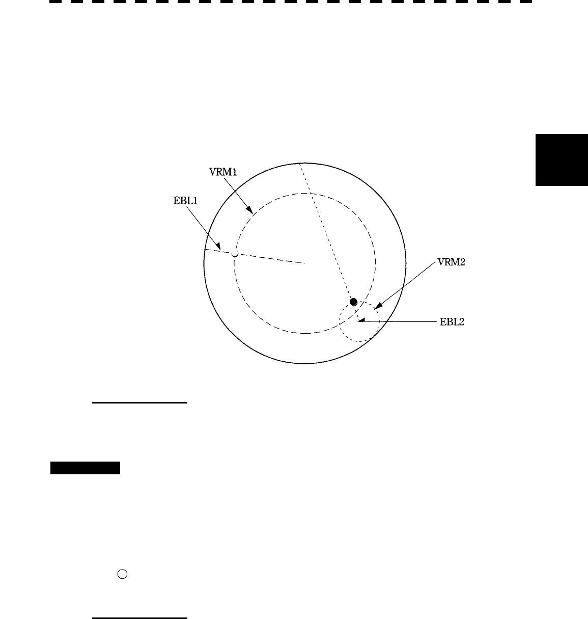
3─30
3
3.5 BASIC OPERATIONS
3.5.4 Display Variable Range Markers [VRM1/VRM2]
This function is to display and select variable range markers (VRMs). Two VRMs are available: VRM1 is
represented as a broken line, and VRM2 as a dotted line. When EBL1 is displayed, VRM1 marker appears on
the EBL1. When EBL2 is displayed, VRM2 marker appears on the EBL2. If the starting point of an EBL is
offset, the center of a VRM marker is positioned at the starting point of the EBL.
VRM markers displayed on EBL1/EBL2
○ mark: VRM1
● mark: VRM2
VRM1 Operation
If VRM2 is selected or VRM1 is not displayed, press [VRM1] to select VRM1 before starting operation.
(The currently selected VRM is shown in reverse video at the lower right of the radar display.)
Procedures 1 Press [VRM1] key.
VRM1 at the lower right of the radar display will be shown in reverse video, and VRM1
becomes operable.
2 Press [VRM1] key again.
The VRM1 display will disappear.
* Button 33 on the radar display on page 2-7 is also available to switch VRM1 between ON and OFF.
VRM Operations
The variable range markers are displayed centering around own ship. Turning the [VRM] control
clockwise makes the VRM larger. Turning the [VRM] control counterclockwise makes the VRM
smaller.
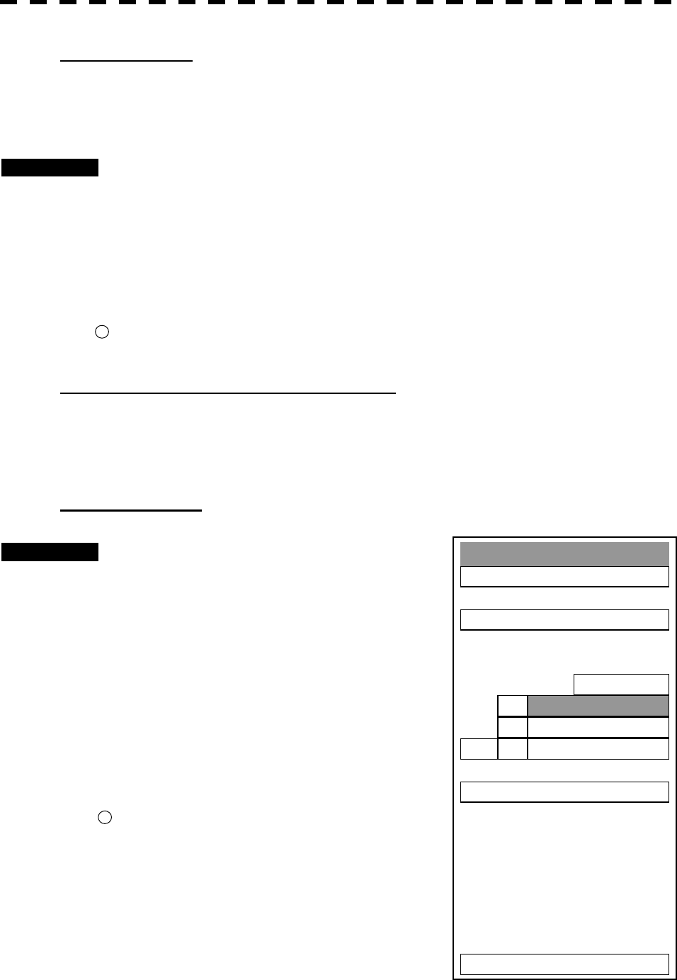
3─31
VRM2 Operation
If VRM1 is selected or VRM2 is not displayed, press [VRM2] key to select VRM2 before starting
operation.
(The currently selected VRM is shown in reverse video at the lower right of the radar display.)
Procedures 1 Press [VRM2] key.
VRM2 at the lower right of the radar display will be shown in reverse video, and VRM2
becomes operable.
2 Press [VRM2] key again.
The VRM2 display will disappear.
* Button 34 on the radar display on page 2-7 is also available to switch VRM2 between ON and OFF.
VRM Range Display (VRM 1/2 Range Unit)
The values of VRM1 and VRM2 currently displayed on the PPI are indicated at the lower right of the
radar display.
The currently operable VRM1 or VRM2 is shown in reverse video beside the range value.
VRM1 Range Unit
Procedures 1 Press [RADAR MENU] key twice.
Press [3] key.
The Marker Setting Menu will appear.
2 Press [3] key.
The VRM1 Range Unit Setting Menu will
appear.
3 Select the unit number to be set,
pressing the numeric keys [1] to [3].
The selected unit will be set.
* Button 37 on the radar display on page 2-7 is also available to
switch VRM1 range unit.
2.
Marker Settin
g
1. EBL1 Settin
g
2. EBL2 Settin
g
3. VRM1 Ran
g
e Unit
nm
4. VRM2 Ran
g
e Unit
nm
5. Parallel Index Line
6. Cursor Settin
g
7. EBL Maneuver Settin
g
0. EXIT
nm1.
km
sm3.
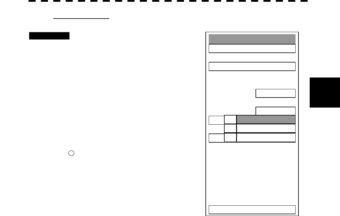
3─32
3
3.5 BASIC OPERATIONS
VRM2 range unit
Procedures 1 Press [RADAR MENU] key twice.
Press [3] key.
The Marker Setting Menu will appear.
2 Press [4] key.
The VRM2 Range Unit Setting Menu will
appear.
3 Select the item you want to set,
pressing the numeric keys [1] to
[3].
The selected item will be set.
* Button 38 on the radar display on page 2-7 is also available to
switch the VRM2 range unit.
2.
Marker Settin
g
1. EBL1 Settin
g
2. EBL2 Settin
g
3. VRM1 Ran
g
e Unit
nm
4. VRM2 Ran
g
e Unit
nm
5. Parallel Index Line
6. Cursor Settin
g
7. EBL Maneuver Settin
g
0. EXIT
nm1.
km
sm3.
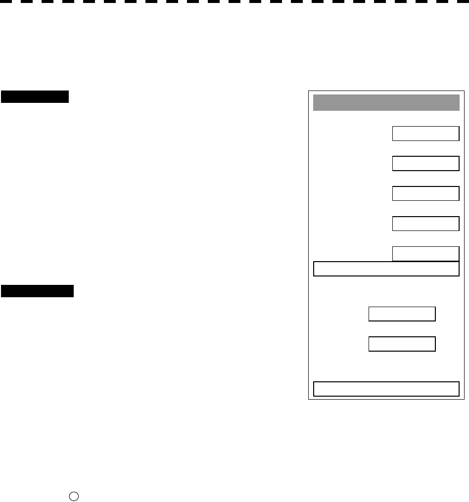
3─33
3.5.5 Display Parallel Index Lines (Parallel Index Line)
Parallel index lines can be displayed.
Procedures 1 Press the [VRM] control.
Parallel index lines and the PI Individual Menu
will appear.
To change the direction of parallel index lines,
turn the [EBL] control.
To change the line intervals, turn the [VRM]
control.
The bearing and interval of parallel index lines
are displayed in the menu area.
2 Press the [VRM] control again.
The parallel index line cursor will be fixed.
Cancellation 1 Press the [VRM] control again.
The parallel index lines display will disappear.
Note: Parallel index lines can be operated only while the parallel index line menu is open. After the menu
closes, the parallel index lines display remains, but the settings of the bearing and interval cannot be
adjusted any more. To adjust the bearing or interval in this case, press the [VRM] control twice to
open the parallel index line menu.
* Button 24 on the radar display on page 2-7 is also available to switch the parallel index lines between ON
and OFF.
Parallel Index Line
1. Display
ON
2. Ran
g
e Link
OFF
3. PI Bearin
g
REF
TRUE
4. PI Floatin
g
OFF
5. PI Bearin
g
Fix
SCREEN
6. PI Individual
PI Bearin
g
°
Interval
nm
0. EXIT
1.00
T 000.0
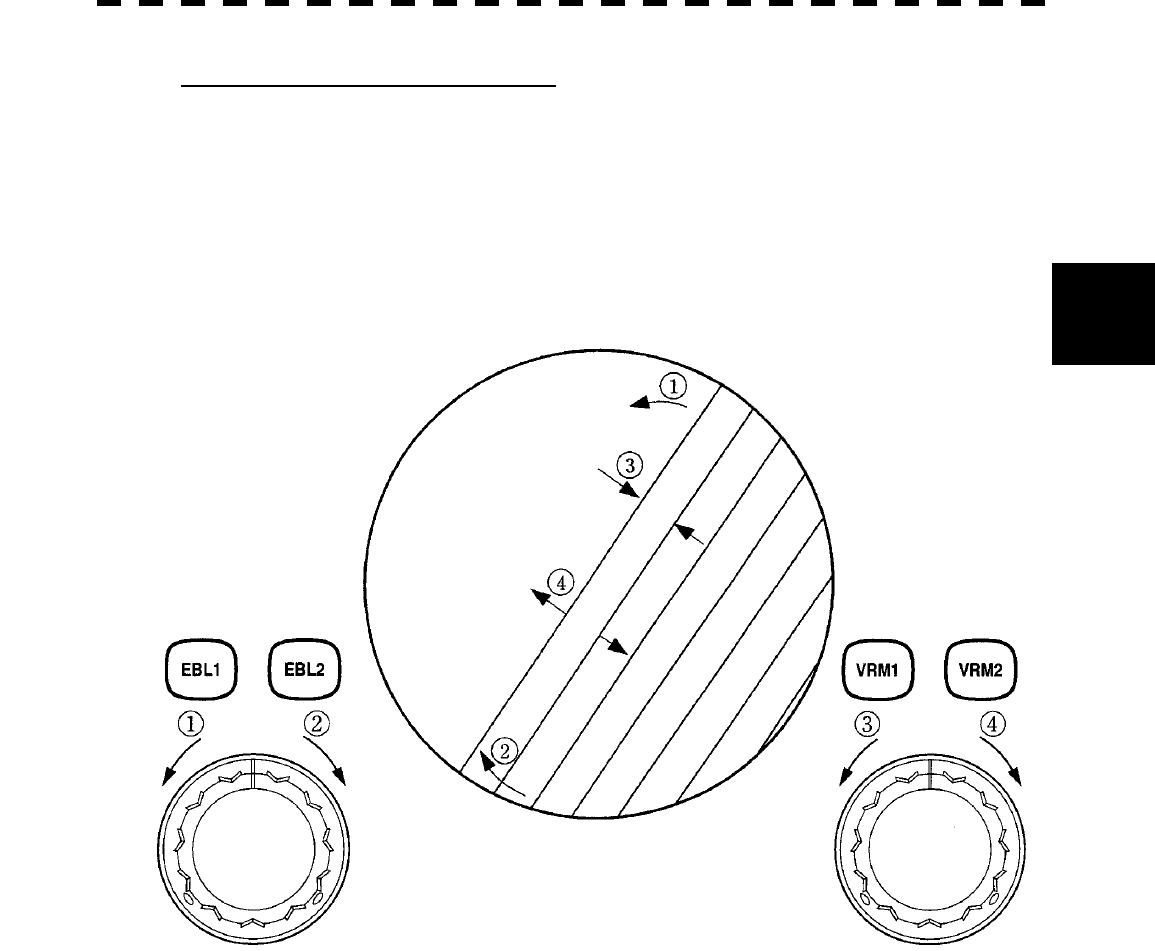
3─34
3
3.5 BASIC OPERATIONS
Operation of Parallel Index Lines
◎ Parallel index lines rotate in the same direction as you turn the [EBL] control.
(①, ②)
◎ The intervals of parallel index lines narrow when you turn the [VRM] control counterclockwise (③),
and widen when you turn the [VRM] control clockwise (④).
Display of Parallel Index Lines
◎ When [RADAR MENU] key is pressed, the parallel index line menu closes and the parallel index
lines are fixed.
During the operation of parallel index lines, pressing the [EBL1] control or [EBL2] control prevents
operating in rotation directions. Pressing the [VRM1] control or [VRM2] control prevents
operation at parallel index line intervals.
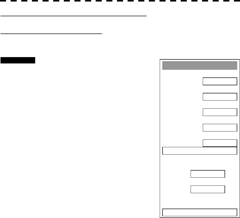
3─35
Parallel Index Line
1. Display
ON
2. Ran
g
e Link
OFF
3. PI Bearin
g
REF
TRUE
4. PI Floatin
g
OFF
5. PI Bearin
g
Fix
SCREEN
6. PI Individual
PI Bearin
g
Interval
0. EXIT
1.00
T 000.0
Setting of Parallel Index Lines (Parallel Index Line)
[I] Parallel Index Line Display (Display)
In the radar menu, you can switch parallel index line display between ON and OFF.
Procedures 1 Press [RADAR MENU] key twice.
Press [3] key.
Press [5] key.
The Parallel Index Line Menu will appear.
2 Press [1].
Parallel Index Line Display is switched between
ON and OFF each time you press [1] key.
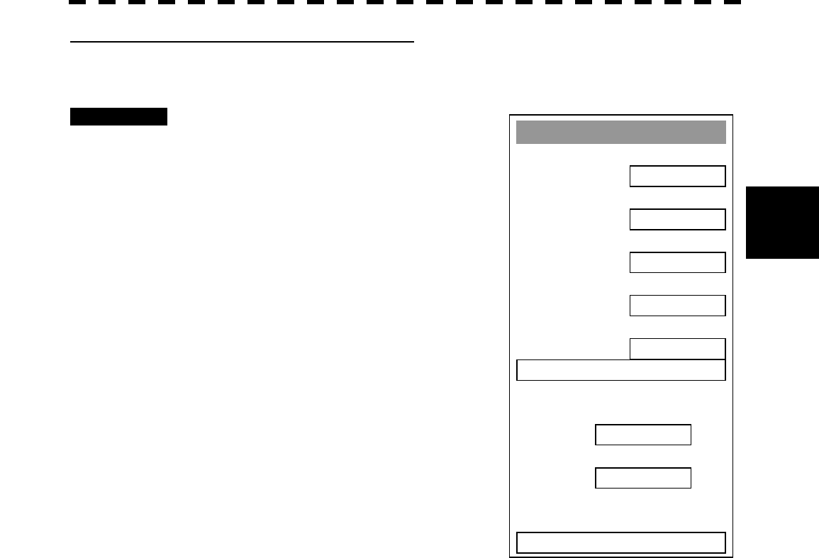
3─36
3
3.5 BASIC OPERATIONS
Parallel Index Line
1. Display
ON
2. Ran
g
e Link
OFF
3. PI Bearin
g
REF
TRUE
4. PI Floatin
g
OFF
5. PI Bearin
g
Fix
SCREEN
6. PI Individual
PI Bearin
g
Interval
0. EXIT
1.00
T 000.0
[II] Parallel Index Line Range Link (Range Link)
When a range is switched, parallel index lines links to a radar range scale and displayed.
Procedures 1 Press [RADAR MENU] key twice.
Press [3] key.
Press [5] key.
The Parallel Index Line Menu will appear.
2 Press [2] key.
Range Link is switched between ON and OFF
each time you press [2] key.
Range Link ON:
If the range is switched, the width between
parallel index lines changes in accordance with
the radar range scale.
Range Link OFF:
If the range is switched, the width between
parallel index lines remains fixed.
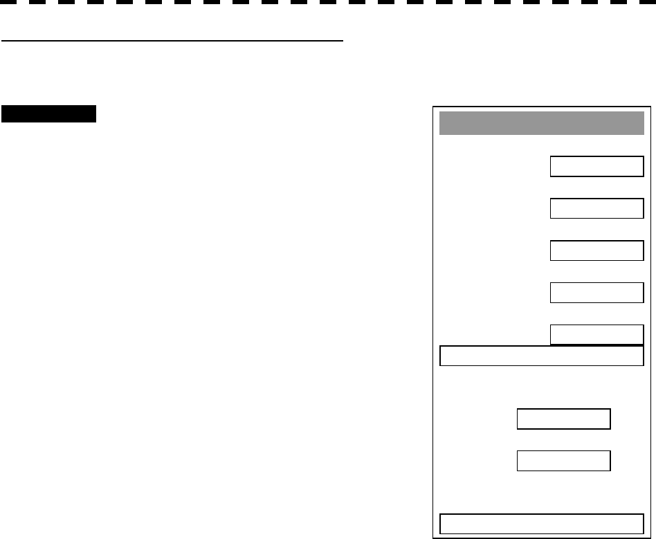
3─37
Parallel Index Line
1. Display
ON
2. Ran
g
e Link
OFF
3. PI Bearin
g
REF
TRUE
4. PI Floatin
g
OFF
5. PI Bearin
g
Fix
SCREEN
6. PI Individual
PI Bearin
g
Interval
0. EXIT
1.00
T 000.0
[III] Parallel Index Line Bearing (PI Bearing REF)
Parallel index line bearing mode can be switched.
Procedures 1 Press [RADAR MENU] key twice.
Press [3] key.
Press [5] key.
The Parallel Index Line Menu will appear.
2 Press [3] key.
The PI Bearing REF mode is switched between
true bearing and relative bearing each time you
press [3] key.
* PI bearing in the parallel index line menu will show which is
selected, true bearing or relative bearing.
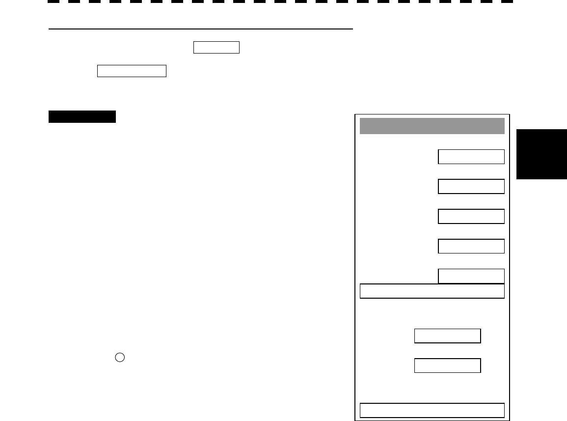
3─38
3
3.5 BASIC OPERATIONS
Parallel Index Line
1. Display
ON
2. Ran
g
e Link
OFF
3. PI Bearin
g
REF
TRUE
4. PI Floatin
g
OFF
5. PI Bearin
g
Fix
SCREEN
6. PI Individual
PI Bearin
g
Interval
0. EXIT
1.00
T 000.0
[IV] Parallel Index Line Start Point Display Mode (PI Floating)
If this function is set to L/L FIX, and the start point of parallel index line moves, the start point of the
parallel index line can be fixed to the latitude/longitude of the start point. If the function is set to
SCREEN FIX, the start point of parallel index line is fixed within the radar display, and the start point
is fixed to the same place on the display even after the own ship moves.
Procedures 1 Press [RADAR MENU] key twice.
Press [3] key.
Press [5] key.
The Parallel Index Line Menu will appear.
2 Press [4] key.
The PI Floating Setting Menu will appear.
3 Select the item you want to display,
pressing the numeric keys [1] to [3].
OFF: Floating mode OFF
SCREEN FIX: Fixes the start point of parallel
index line to the radar display.
L/L FIX: Fixes the parallel index line
with latitude and longitude.
* Button 23 on the radar display on page 2-7 is also available for
switching.
Note: Setting the function to the L/L Fix mode needs course data and latitude/longitude data.
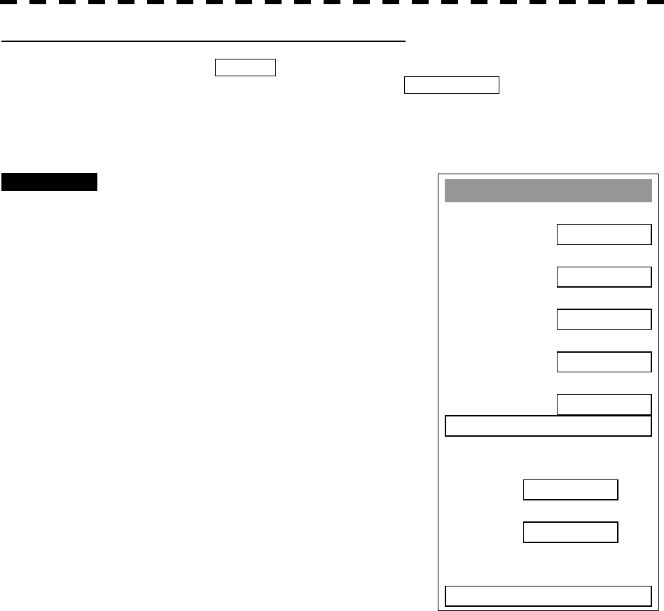
3─39
Parallel Index Line
1. Display
ON
2. Ran
g
e Link
OFF
3. PI Bearin
g
REF
TRUE
4. PI Floatin
g
OFF
5. PI Bearin
g
Fix
SCREEN
6. PI Individual
PI Bearin
g
Interval
0. EXIT
1.00
T 000.0
[V] Parallel Index Line Bearing Fix Mode (PI Bearing Fix)
If this function is set to ANGLE , the parallel index line also rotates in accordance with the bearing
while the own ship is turning. If the function is set to SCREEN FIX , the parallel index lines are
fixed within the radar display even while the own ship is turning. The parallel index lines are displayed
at the same place even while the own ship is turning.
Procedures 1 Press [RADAR MENU] key twice.
Press [3] key.
Press [5] key.
The Parallel Index Line Menu will appear.
2 Press [5] key.
The PI Bearing Fix Setting Menu will appear.
ANGLE: Links the parallel index lines
with the bearing of the own
ship.
SCREEN FIX: Fixes the parallel index lines
to the radar display.

3─40
3
3.5 BASIC OPERATIONS
PI Individual
1. Line 1
ON
2. Line 2
ON
3. Line 3
ON
4. Line 4
ON
5. Line 5
ON
6. Line 6
7. Line 7
0. EXIT
ON
ON
[VI] Individual Display of Parallel Index Line (PI Individual)
Individual parallel index lines can be switched between ON and OFF.
Procedures 1 Press [RADAR MENU] key twice.
Press [3] key.
Press [5] key.
The Parallel Index Line Menu will appear.
2 Press [6] key.
The PI Individual Setting Menu will appear.
3 Select the item for which you want to
display or not to display, pressing the
numeric keys [1] to [7].
Individual setteing is switched between ON
and OFF each time you press each numeric
keys.
ON: Displayed
OFF : Not displayed
* The line nearest to the own ship is specified as Line1.
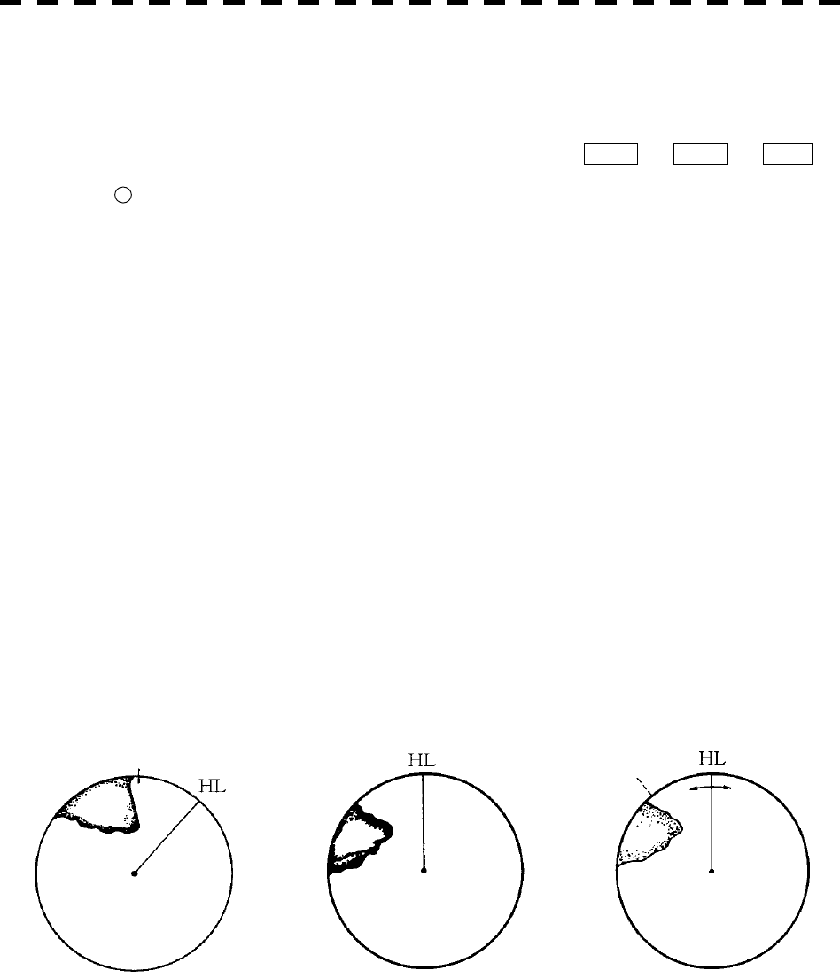
3─41
3.5.6 Switch Bearing Display Mode [AZI MODE]
The bearing display mode is switched in the sequence of [NORTH UP] (true bearing), [HEAD UP] (relative
bearing), and [COURSE UP] (course-up bearing) each time [AZI MODE] key is pressed.
The indication at the upper left of the radar display changes in sequence of HUP ® NUP ® CUP .
* Button 5 on the radar display on page 2-7 is also available to switch the radar bearing display.
True Bearing Mode [North Up]
The video is displayed so that the zenith of the PPI (0° on range rings) points to the due north. Fixed
targets do not flicker and are easily identified on the chart, and the true bearing of a target can easily
be read out.
Relative Bearing Mode [Head Up]
The video is displayed so that the ship’s heading line points to the zenith of the PPI (0° on range
rings). Since targets are displayed in their directions relative to the ship’s heading line, the operator
can view the video in the same field of view as in operating the ship at sea. This mode is suitable
for watching over other ships.
Course-up Bearing Mode [Course Up]
By pressing [AZI MODE] key, the own ship’s course is fixed pointing to the zenith of the PPI (0° on
range rings) points to the due north. In the same way as in the North-up mode, fixed targets do not
flicker, and are stabilized even if the ship is yawing. The bearing of the heading line varies by the
same shift of own ship’s course. To change the course, press [AZI MODE] key several times to
select the Course-up mode, and set a new course.
N
orth
N
orth
North Head-up Mode Course-up Mode
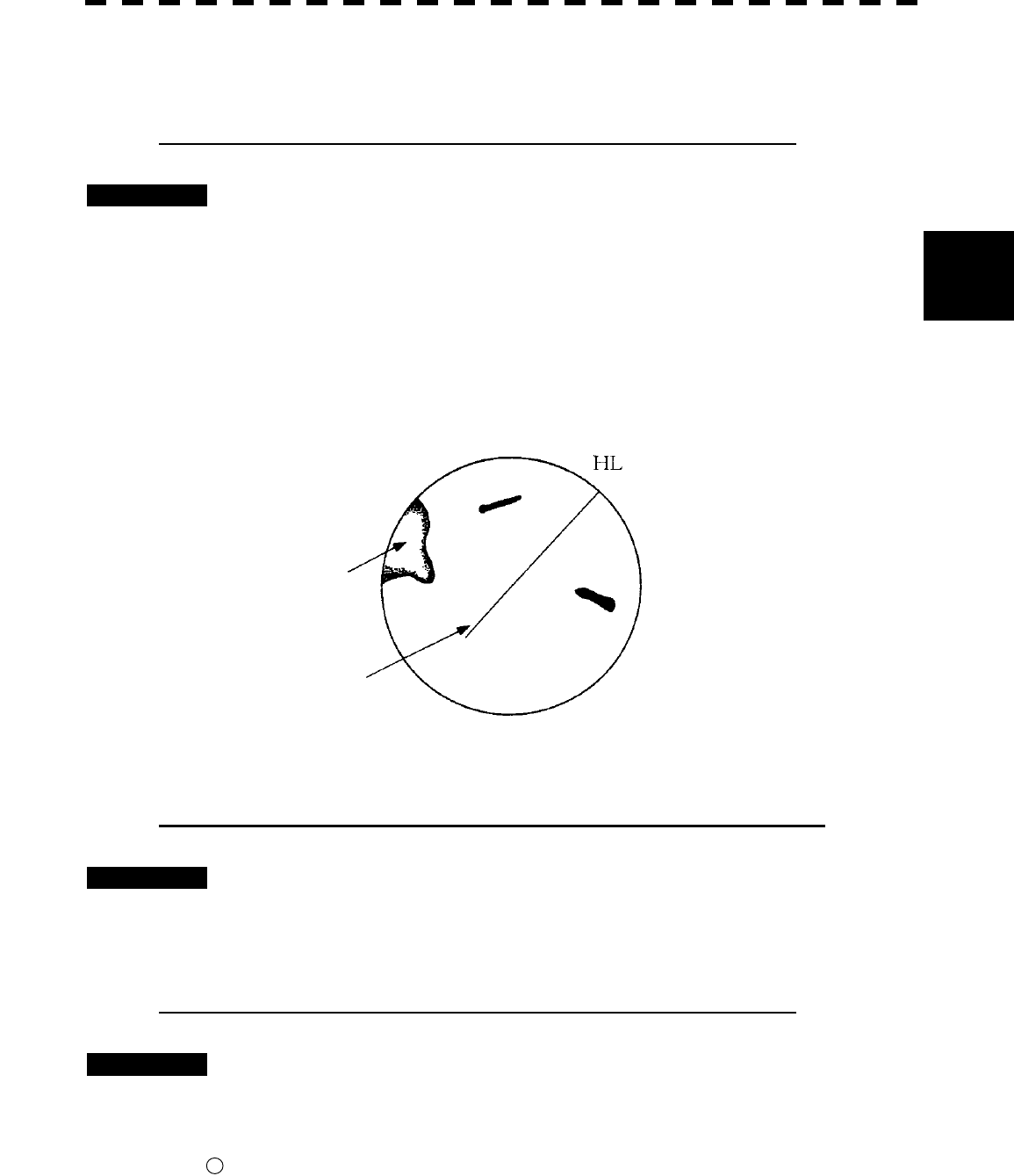
3─42
3
3.5 BASIC OPERATIONS
3.5.7 Switch True/Relative Motion Display Mode [TM/RM]
Switching Relative Motion (RM) Mode to True Motion (TM) Mode
Procedures 1 Press [TM/RM] key.
The true motion mode will be selected. In the true motion mode, the own ship’s position
on the radar display moves depending upon its speed and course and the influence of the
current. Land and other fixed targets are fixed on the radar display and only actually
moving targets move on the radar display. When the true motion mode is selected, the
own ship’s position is set to about 60% of the display radius in the opposite direction to its
course allowing for the influence of the current. Own ship starts moving depending
upon its speed and course and the influence of the current. Subsequently, when own ship
arrives at the position of about 66% of the display radius, it is automatically reset to its
initial position at about 60% of the display radius in the opposite direction to its course
allowing for the influence of the current.
Resetting Own Ship to its Initial Position in True Motion (TM) Mode
Procedures 1 Press [TM/RM] key for 2 seconds.
Own ship will be reset to its initial position as established when the relative motion mode
is changed to the true motion mode. The ship starts moving from that position.
Switching True Motion (TM) Mode to Relative Motion (RM) Mode
Procedures 1 Press [TM/RM] key.
The relative motion mode will be selected. Own ship returns to the center of the radar
display.
* Button 4 on the radar display on page 2-7 is also available to switch between true motion and relative
motion. Keep pressing the button for two seconds can reset the position of the own ship during true
motion.
Fixed on the radar display
Moving depending on own
ship’s speed
True Motion Display
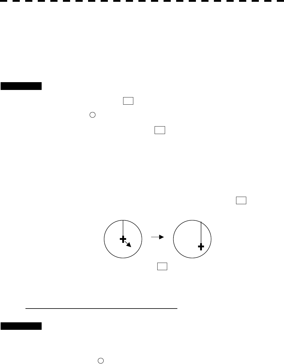
3─43
3.5.8 Move Own Ship’s Display Position [OFF CENT]
The own ship’s position can be moved from the display center to any position within 66% of the display radius.
This function is convenient for observing a wide coverage in any direction.
Note: This function is not available on the 96 NM range.
Procedures 1 Press [OFF CENT] key.
The cross cursor mark + will appear at the own ship’s position on the radar display.
* Button 20 on the radar display on page 2-7 is also available to activate OFF Center.
2 Move the cross cursor mark + (own ship’s display position) to a
desired position by using the trackball.
While the cross cursor mark is moving, the own ship’s display position moves following
the cross cursor mark.
When it moves to a position outside 66% of the display radius, the center position is
limited to a position within 66% of the display radius.
3 Press [ENT] key.
The own ship’s display position will be fixed to the cross cursor mark + .
Returning Own Ship’s Position to the Center
Procedures 1 Press [OFF CENT] key for 2 seconds.
Note: Close the menu before using this function. While the menu is open, the function cannot be
used.
* You can keep pressing button 20 on the radar display for two seconds on page 2-7 to return the own ship
position to the center.
HL HL
Move the cross cursor mark +
to a desired position.
Press [ENT] key.
The own ship’s display position
will be fixed.
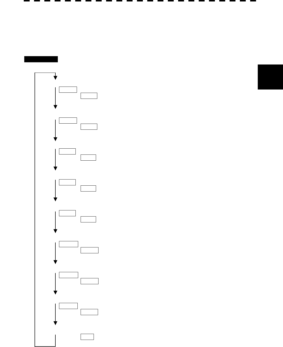
3─44
3
3.5 BASIC OPERATIONS
3.5.9 Display Other Ships’ Trails [TRAILS]
Other ships’ movements and speeds can be monitored from the lengths and directions of their trails, serving for
collision avoidance. The trail length varies according to setting.
The setting is described on the next page.
Procedures
Trail length setting in SHORT mode:
Press [TRAILS] key.
15 sec will be selected.
“TRAILS 15 sec ” will appear at the lower left of the radar display.
The trails (15 sec in length) will appear after other ships’ symbols.
Press [TRAILS] key.
30 sec will be selected.
“TRAILS 30 sec ” will appear at the lower left of the radar display.
The trails (30 sec in length) will appear after other ships’ symbols.
Press [TRAILS] key.
1 min will be selected.
“TRAILS 1 min ” will appear at the lower left of the radar display.
The trails (1 min in length) will appear after other ships’ symbols.
Press [TRAILS] key.
3 min will be selected.
“TRAILS 3 min ” will appear at the lower left of the radar display.
The trails (3 min in length) will appear after other ships’ symbols.
Press [TRAILS] key.
6 min will be selected.
“TRAILS 6 min ” will appear at the lower left of the radar display.
The trails (6 min in length) will appear after other ships’ symbols.
Press [TRAILS] key.
10 min will be selected.
“TRAILS 10 min ” will appear at the lower left of the radar display.
The trails (10 min in length) will appear after other ships’ symbols.
Press [TRAILS] key.
15 min will be selected.
“TRAILS 15 min ” will appear at the lower left of the radar display.
The trails (15 min in length) will appear after other ships’ symbols.
Press [TRAILS] key.
CONT will be selected.
“TRAILS CONT ” will appear at the lower left of the radar display.
The trails (in unlimited length) will appear after other ships’ symbols.
Press [TRAILS] key.
“TRAILS OFF ” will appear at the lower left of the radar display.
The trails of other ships will disappear.
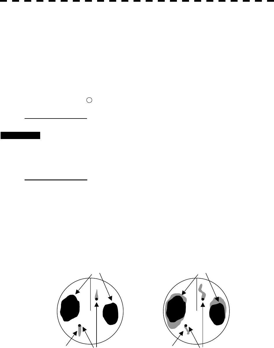
3─45
SHORT mode: 15 sec, 30 sec, 1 min, 3 min, 6 min, 10 min, 15 min, and CONT
MID mode: 30 sec, 1 min, 3 min, 6 min, 10 min, 15 min, 30 min, and CONT
LONG mode: 1 min, 3 min, 6 min, 10 min, 15 min, 30 min, 60 min, and CONT
SUPER LONG mode: 30 min, 1 hr, 2 hr, 3 hr, 4 hr, 5 hr, 6 hr, 7 hr, 8 hr, 9 hr, 10 hr, 11 hr, 12 hr and
CONT
A trail length can also be changed by using the multi-function control. (Refer to page 3-56.)
Stored trails cannot be erased even when the trail lengths are changed by using [TRAILS] key. Even
after the trails display is turned off, the past trails can be displayed traced back by setting a desired time.
The system is plotting trails even while the trails display is off.
* Button 16 on the radar display on page 2-7 is also available to change trail length.
Erasing Trails Data
Procedures 1 Hold down [TRAILS] key for 5 seconds.
All the stored trails data will be erased. The system starts plotting trails in initial state.
When [TRAILS] key is pushed for 2 seconds, a RADAR Trails Setting menu will be
displayed. Furthermore, data will be erased if it continues pushing.
Trails Motion Mode
There are two types of trails: relative motion trails and true motion trails.
Relative motion trails: The system plots the trails of a target at a position relative to the own ship.
The operator can easily judge whether the target is approaching the own
ship.
While the own ship is moving, the system also plots the trails of land and
other fixed targets.
True motion trails: The system plots the absolute motion trails of a target, irrespective of the
own ship’s position.
The operator can easily judge the course and speed of the target.
The system does not plot the trails of land and other fixed targets.
Land
Ship
Trails
Land
Ship
Trails
True Motion Trails Relative Motion Trails
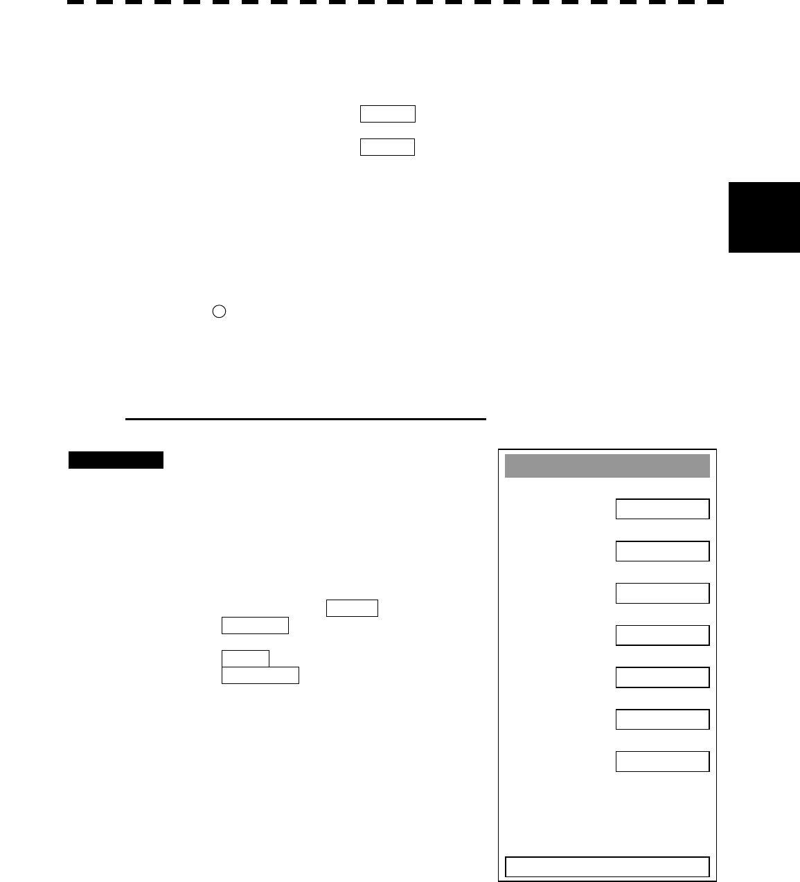
3─46
3
3.5 BASIC OPERATIONS
Trails modes provided with this system vary depending on the motion mode.
With true motion (TM) mode: Only the true motion trails mode is available.
With relative motion (RM) mode: The relative motion trails mode or true motion trails mode is
selectable.
RM(R) is indicated while the relative motion trails mode is
active.
RM(T) is indicated while the true motion trails mode is
active.
While the true motion trails mode is active, this system enables the continuous use of true motion
trails even if any of the following operations is performed:
· Motion display mode change [TM/RM] key
· TM reset [TM/RM] key
· Bearing display mode change [AZI MODE] key
· Center move [OFF CENT] key
· MAP display on/off [MAP] key
* Button 17 on the radar display on page 2-7 is also available to change trial motion mode.
Note: Accurate true bearing signals and speed signals are necessary for using the true motion trails
mode.
Changing Motion Mode of Trails (Trails mode)
Procedures 1 Press [RADAR MENU] key twice.
Press [2] key.
The RADAR Trails Setting Menu will appear.
2 Press [2] key.
The setting of radar trails display mode will be
switched between TRUE and
RELATIVE.
TRUE : True motion trails
RELATIVE : Relative motion trails
® For other settings, see section 3.10.2, page 3-100
RADAR Trails Settin
g
1. Trails Interval
6 min
2. Trails Mode
TRUE
3. Trails REF Level
LEVEL2
4. Trails Reduction
OFF
5. Time/Cont Combine
OFF
6. Trails Process
OFF
7. Max Interval
SHORT
0. EXIT

3─47
3.5.10 Switch Pulse Length (GAIN/PL)
Procedures 1 Press [GAIN/PL] control.
The transmitter pulse length changes cyclically in the following sequence each time
[GAIN/PL] control is pressed:
SP ® MP ® LP ® SP The currently selected pulse length is indicated at
the upper left of the radar screen.
The pulse length can be changed only when the range is set to 0.75, 1.5, 3, 6, or 12 NM.
With SP selected:
The transmitter pulse becomes shorter, and the range resolution improves.
The effect of suppressing sea clutter returns and rain/snow clutter returns heightens.
Recommended condition for selection:
In bays/harbors where targets are densely crowded
Rough sea state due to torrential rain or stormy weather
With MP selected:
The normal transmitter pulse length is set.
Both range resolution and sensitivity are appropriately set.
Recommended condition for selection:
General navigation
With LP selected:
The transmitter pulse becomes longer, and sensitivity improves.
Small targets are zoomed and are easy to observe.
Recommended condition for selection:
Detection of small targets in good weather conditions
* Button 3 on the radar display on page 2-7 is also available to switch pulse width.
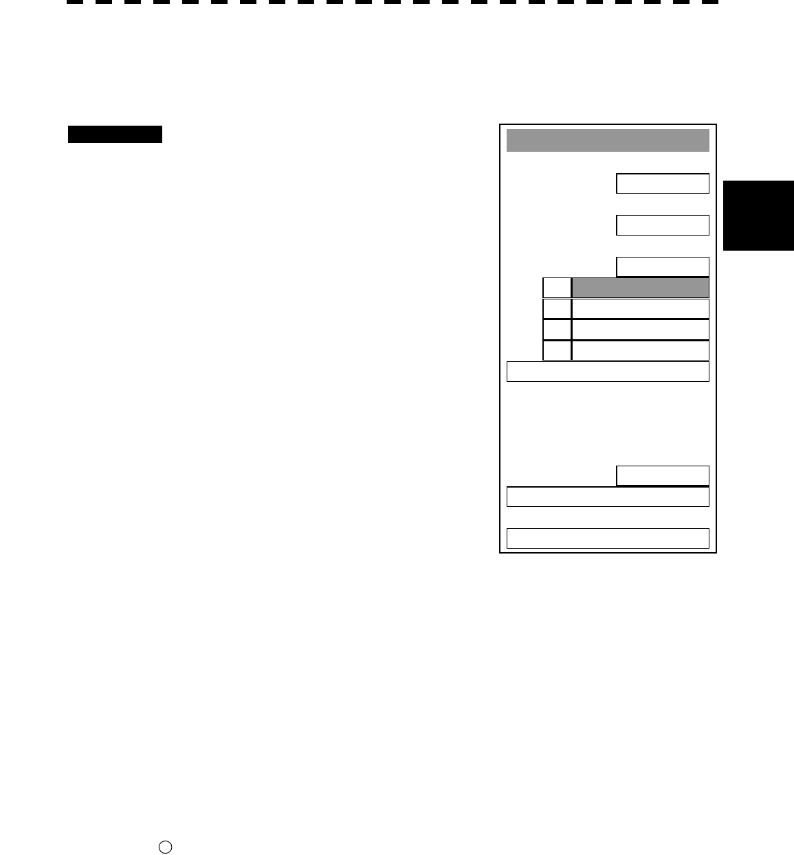
3─48
3
3.5 BASIC OPERATIONS
Main Menu
1. I
R
IR OFF
2. Process
PROC OFF
3. Tar
g
et Enhance
OFF
4. ZOOM
OFF
5. START
OFF
6. NAV Information >
7.
8. Graphic Display
ON
9. RAD
A
R Menu ( Plot )
0. EXIT
ENH OFF1.
ENH LEVEL12.
ENH LEVEL23.
ENH LEVEL34.
3.5.11 Expand Targets (Target Enhance)
This function expands targets shown on the radar display.
Procedures 1 Press [RADAR MENU] key.
The Main Menu will appear.
2 Press [3] key.
The Target Enhance Selection Menu will
appear.
3 Select the mode number to be set,
pressing the numeric keys [1] to [4].
Target expansion modes
ENH OFF Expansion off: Select this mode particularly when resolution is required.
ENH LEVEL1 Expansion - small: Select this mode in general.
Radar echoes are expanded by 1 scale in all directions.
ENH LEVEL2 Expansion - medium: Select this mode to easily view the radar video.
Radar echoes are expanded by 2 scales in all directions on the
display.
ENH LEVEL3 Expansion - large: Select this mode to detect small targets such as buoys.
The expansion near a screen center is added to ENH LEVEL2.
Note: When ENH LEVEL3 is selected, sea clutter returns and rain/snow clutter returns are apt to be
expanded. When using this expansion mode, operate [AUTO-SEA] control and
[AUTO-RAIN] control to suppress sea clutter returns and rain/snow clutter returns.
In general, ENH LEVEL1 or ENH LEVEL2 should be selected.
* Button 11 on the radar display on page 2-7 is also available to switch the target enhance mode.
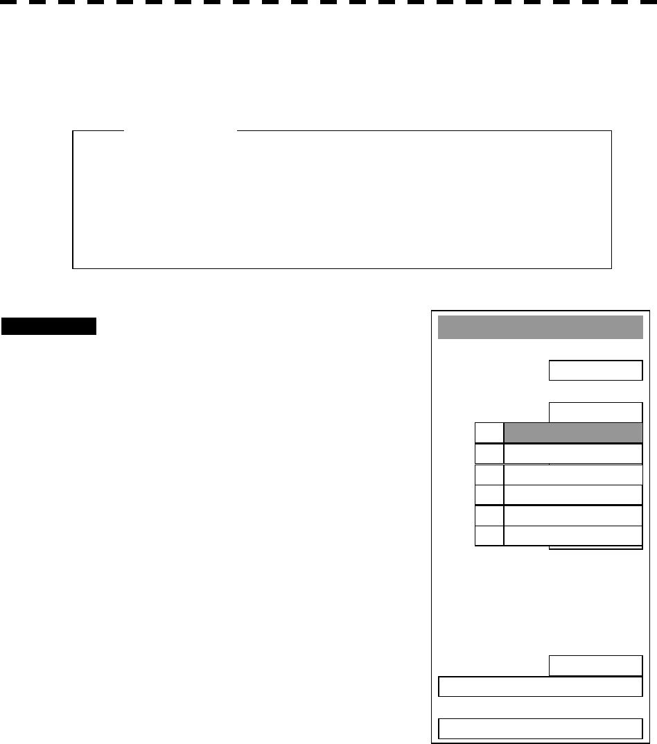
3─49
l When viewing a radar beacon, SART signal, or fast
moving target on the radar display, select PROCESS
OFF (video process off).
Main Menu
1. I
R
IR OFF
2. Process
PROC OFF
3. Tar
g
et Enhance
OFF
4. Zoom
OFF
5. SART
OFF
6. NAV Information
7
.
8. Graphic Display
ON
9. RADAR Menu ( Plot )
0. EXIT
4SCAN COR
R
3.
5SCAN COR
R
4.
PROC OFF1.
3SCAN COR
R
2.
REMAIN5.
PEAK HOLD6.
3.5.12 Use Video Process (Process)
This function reduces unnecessary noise to highlight targets.
Procedures 1 Press [RADAR MENU] key.
The Main Menu will appear.
2 Press [2] key.
The Process Selection Menu will appear.
3 Select the mode number to be set,
pressing the numeric keys [1] to [6].
The selected mode will be set.
Video process modes
PROC OFF Video process off: Select this mode in general.
3SCAN CORR Correlative process 1: Select this mode when many rain/snow clutter returns are
detected.
4SCAN CORR Correlative process 2: Select this mode to highlight targets while suppressing sea clutter
returns.
5SCAN CORR Correlative process 3: Select this mode to detect small targets hidden by sea clutter
returns.
REMAIN Video process 4: Select this mode when own ship yaws wildly.
PEAK HOLD Video process 5: Select this mode to detect small targets of which detection
probability is low.
Attention
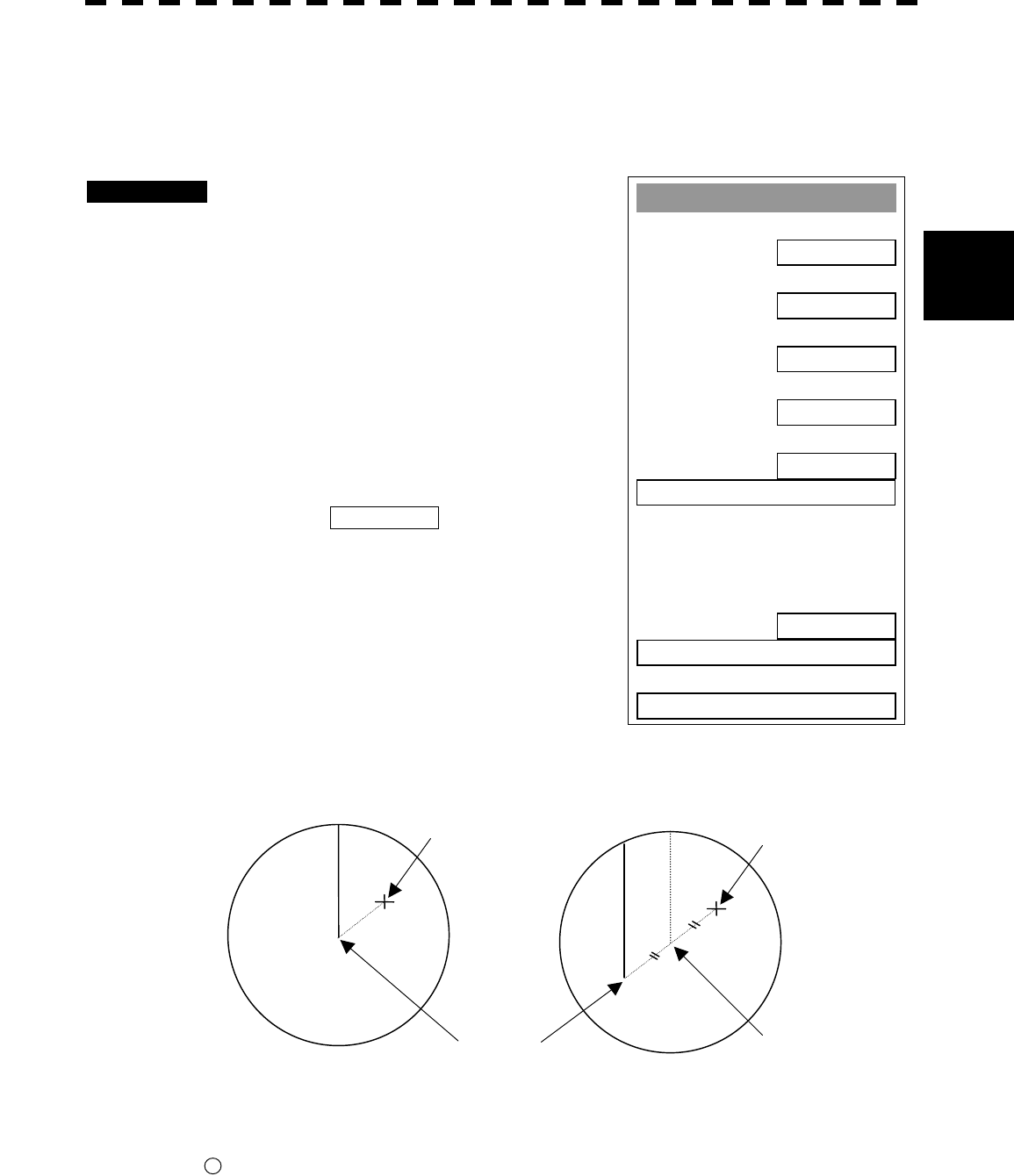
3─50
3
3.5 BASIC OPERATIONS
3.5.13 Zoom
This function doubles the size of radar video near a specified position.
Attention If the range is 0.125 NM, this function is not available.
Procedures 1 Press [RADAR MENU] key.
The Main Menu will appear.
2 Press [4] key.
The setting of the zoom mode will be switched
between ON and OFF.
OFF : Not zoomed
ON : Zoomed
This function is not available at places where
the size exceeds 66% of the radius of the
display.
3 With ZOOM ON selected, move
the cross cursor mark to the position
to be zoomed, and press [ENT] key.
The position will be zoomed.
Using the cross cursor mark as reference, the zoom function doubles the size of a radar video
with the midpoint between the cursor mark and own ship’s position being set to the center of
radar display.
* Button 9 on the radar display on page 2-7 is also available to switch the zoom function between ON and
OFF. "x" blinks at the screen lower right during a ZOOM display.
Cross cursor mark
Own ship’s position Center of radar display
Cross cursor mark
Own Ship’s Position before
Zooming position Own Ship’s Position after
Zooming
Main Menu
1. I
R
IR OFF
2. Process
PROC OFF
3. Tra
g
et Enhance
OFF
4. Zoom
OFF
5. SART
OFF
6. NAV Information
8. Graphic Display
ON
9. RADAR Menu ( Plot )
0. EXIT

3─51
3.5.14 Use Marker [MOB]
The marker function displays a dotted line from the marker input position to the own ship’s position, and
indicates the range, bearing, and required time from the own ship to the marker.
Procedures 1 Press [MOB] key.
A marker will be displayed at the own ship’s position on the radar display at the moment
when [MOB] key is pressed.
The own ship and the marker are connected with a dotted line.
Even when the own ship moves, the marker is fixed at the latitude and longitude. Thus,
if a marker is put to an important position, the ship can return to the position regarding the
marker as a target.
Cancellation 1 Hold down [MOB] key for 2 seconds.
The marker will disappear.
3─52
3
3.5 BASIC OPERATIONS
3.5.15 Marking [MARK]
A maximum of 20 marks can be indicated at arbitrary positions on the radar display.
A mark created on the radar display holds the latitude and longitude.
[I] Creating Marks
Procedures 1 Press [MARK] key.
[□] will appear in the CURSOR field at the upper right of the radar display.
2 Put the cross cursor mark + on the position where a mark is to be
created, and press [ENT] key.
The cross cursor mark + will be changed into the [□] mark and fixed on the radar
display. To enter more [□] marks, repeat step 2.
Up to 20 marks can be entered.
Note: If more than 20 marks are created, the oldest mark is cleared and the newly created mark is
displayed.
[II] Clearing Marks
Procedures 1 Press [MARK] key.
The [□] mark will appear in the CURSOR field at the upper right of the radar display.
2 Put the cross cursor mark + on the mark to be cleared.
The [□] mark will disappear. To clear another [□] mark, repeat step 2.
To clear all [□] marks, press [MARK] key and then hold down [CLR] key.
* Pressing button 19 on the radar display on page 2-7 changes the cursor mode. When "□" appears, the cross
cursor is available to create "□" mark.
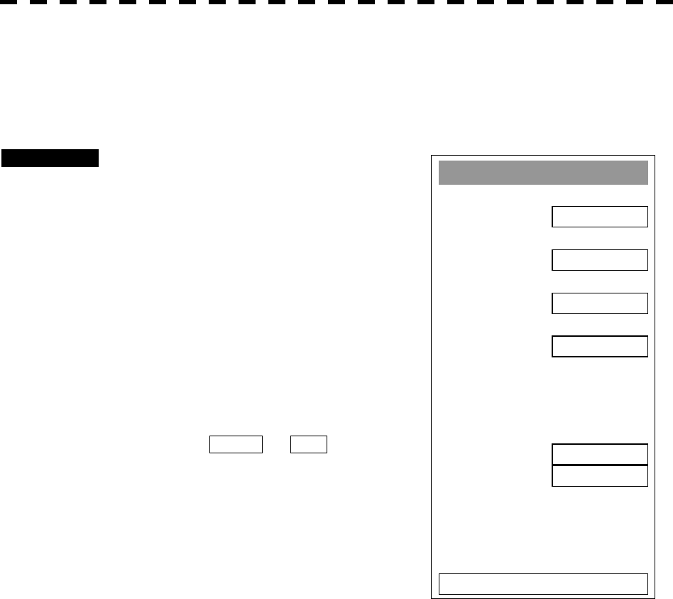
3─53
3.5.16 Operate EBL Maneuver Function (EBL Maneuver)
[I] Initial Setting (Reach,Turn Mode, Turn Set)
Procedures 1 Press [RADAR MENU] key twice.
Press [3] key.
Press [7] key.
The EBL Maneuver Setting Menu will
appear.
2 Press [2] key.
The CODE INPUT Menu will appear.
Enter the Reach value and select ENT.
3 Press [3] to select Turn Mode.
The setting of turn mode will be switched
between RADIUS and RATE.
RADIUS: Constant turn diameter (NM)
RATE: Constant turn speed (deg/min)
4 Press [4] key.
The CODE INPUT Menu will appear.
Enter the Turn Set value and select ENT.
Note: If the initial setting is not correct, the maneuver curve is affected.
EBL Maneuver
1. EBL Maneuver
OFF
2. Reach
1000 m
3. Turn Mode
RADIUS
4. Turn Set
1.0 nm
HEADING
R **.* °
WOL
*** nm
0. EXIT
T **.* °

3─54
3
3.5 BASIC OPERATIONS
[II] Creating Maneuver Curve (EBL Maneuver)
Procedures 1 Press [1] key while the EBL Maneuver menu is open.
EBL Maneuver will be set to ON.
A supplemental line, a maneuver curve, and WOL will appear on the radar display.
2 Set the starting point of the supplemental line using the trackball, and
set the bearing of the supplemental line using the [EBL] control.
The bearing of the supplemental line will be the final bearing in which the own ship is to
move.
The position of WOL will change depending on the bearing of the supplemental line.
If the WOL is behind the own ship’s position, the line color of WOL will change.
3 Press [ENT] key.
The setting will be determined. However, if the WOL is behind the own ship’s position
at this point, the pressing of [ENT] key is rejected, and the setting is not determined.
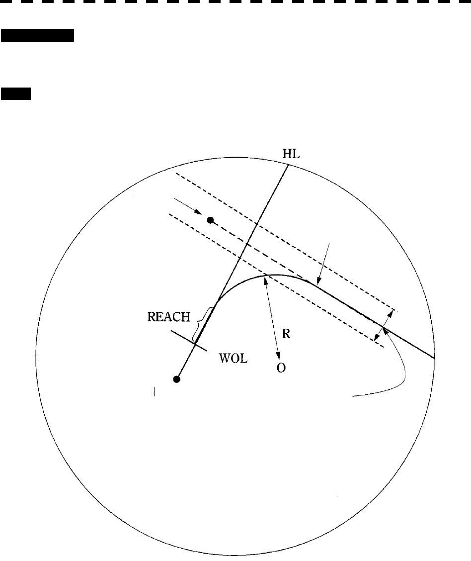
3─55
Cancellation 1 Press [1] key.
The EBL Maneuver function will be set to OFF.
Exit 1 Press [RADAR MENU] key.
The EBL Maneuver Menu will close.
WOL: Steering point
REACH: Distance from when the wheel is steered to when the ship begins to turn
R: Turning radius
Supplemental line
Maneuver curve
Own ship’s position Scheduled route
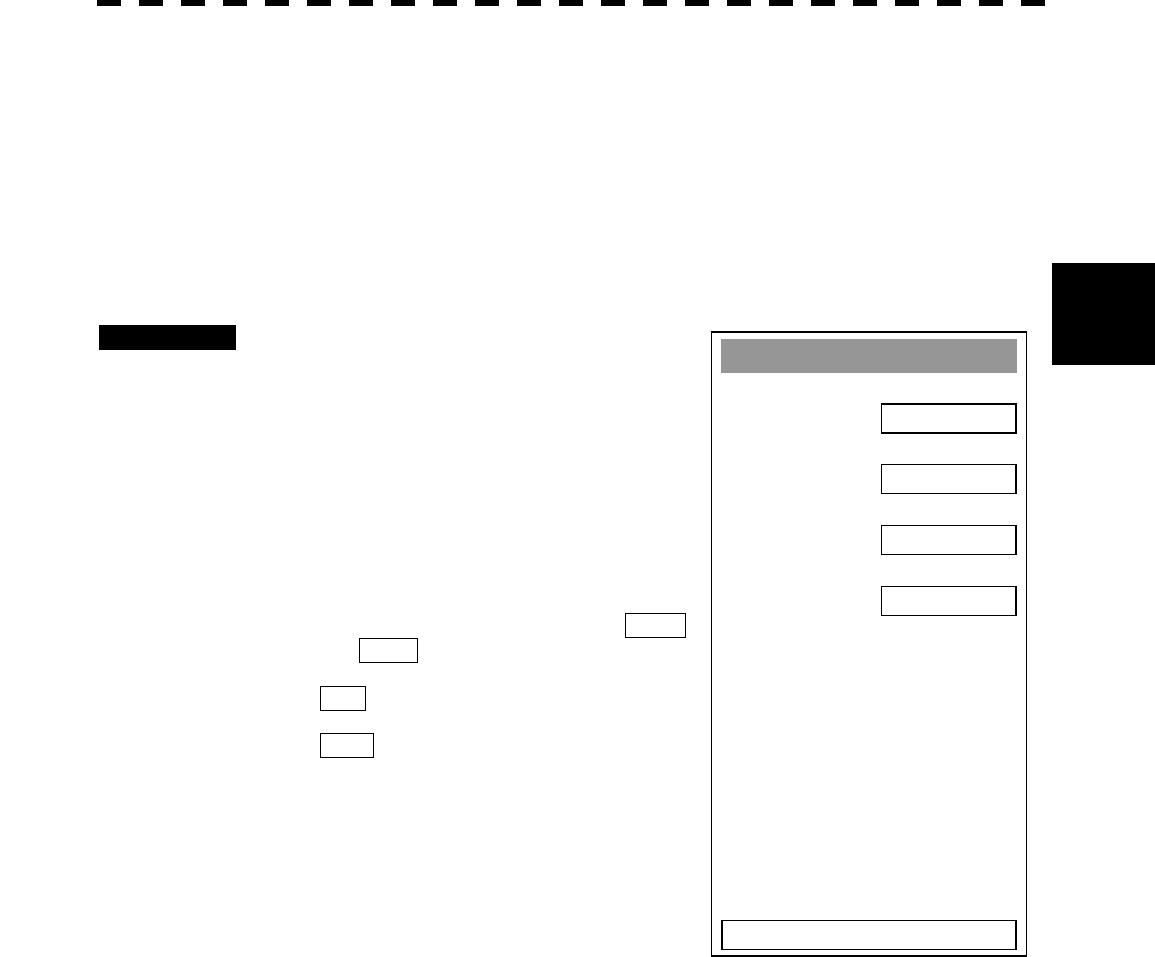
3─56
3
3.5 BASIC OPERATIONS
3.5.17 Operate Multi-Function Control [MULTI]
The multi-function control [MULTI] is provided to change the settings of parameters such as the length of
radar trails. Turn the control to select a parameter. Radar operation is simplified by using the control.
[I] Initial Setting (Multi Dial Setting)
Set parameters that can be operated with the multi-function control.
A parameter set to ON can be called by turning [MULTI] control.
Procedures 1 Press [RADAR MENU] key twice.
Press [8] key.
Press [2] key.
The Multi Dial Setting Menu will appear.
2 Press the numeric key of the number
of the parameter whose setting is to
be changed.
The setting will be switched between ON
and OFF .
ON : Can be operated with the
multi-function control.
OFF : Cannot be operated with the
multi-function control.
Parameters
1. Vector Length: Vector length of ARPA/ATA
2. Trails Length: Length of radar trails
3. ATA TGT Display No.: ARPA/ATA target number for which values are to be
displayed
4. C-UP Angle: Course in course-up mode bearing mode
Multi Dial Settin
g
1.
V
ector Len
g
th
ON
2. Trails Len
g
th
ON
3. ATA TGT Display No.
ON
4.
C
-UP An
g
le
OFF
0. EXIT
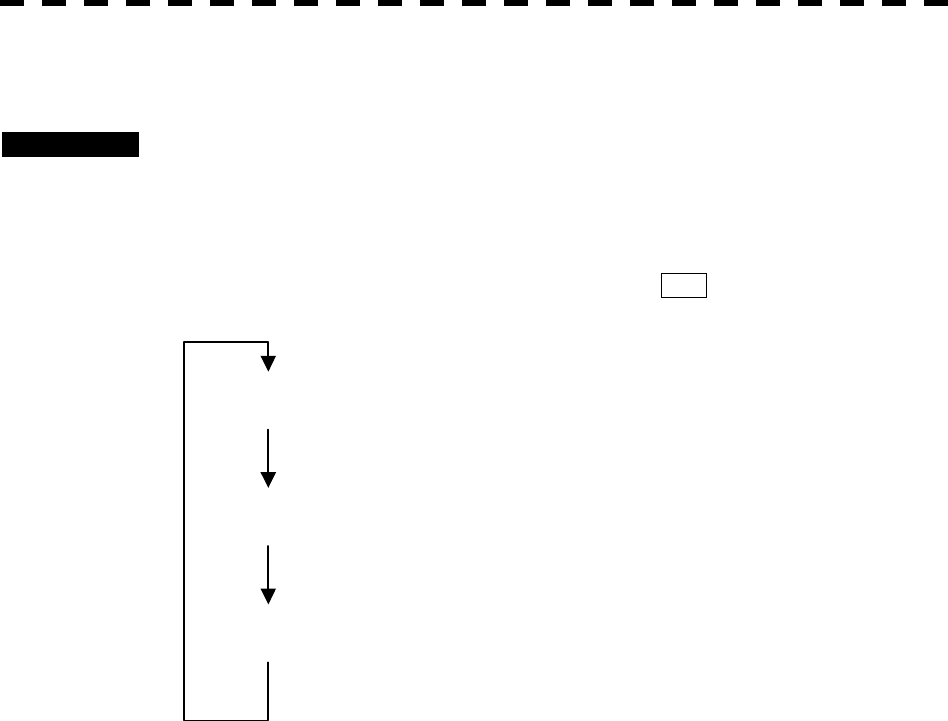
3─57
[II] Using Multi-function Control
Procedures 1 Press the [MULTI] control to select the parameter whose setting is to be
changed.
Parameters will be selected sequentially each time the [MULTI] control is pressed.
The currently selected parameter is indicated at the lower right of the radar display.
For example, if three parameter 1-3 are initially set to ON , they are selected in the
following sequence each time the [MULTI] control is pressed:
MULTI (VECTOR)
Press the [MULTI] control.
MULTI (TRAILS)
Press the [MULTI] control.
MULTI (TGT No.)
Press the [MULTI] control.
2 Turn the [MULTI] control to change the setting.
The preset values of the selected parameter will change sequentially.
Stop turning the control when the desired value appears.
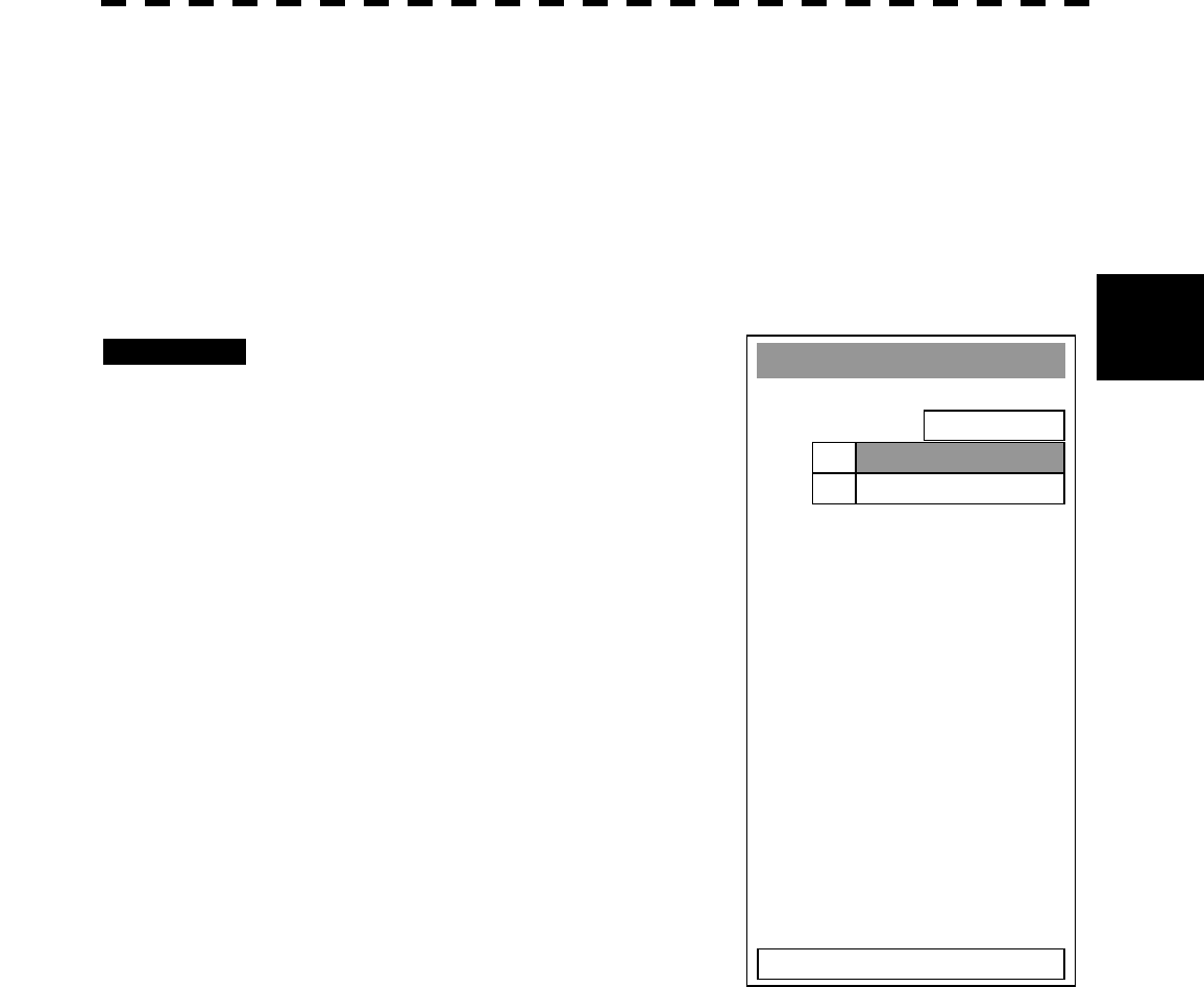
3─58
3
3.5 BASIC OPERATIONS
3.5.18 Operate User Key Switches [User Key 1/2]
Users can freely make settings with [USER KEY1] key and [USER KEY2] key.
By using the switches, users can open a frequently used menu by only single operation, or assign special
functions, which are not on the standard operation panel, to the user key switches.
[I] Initial Setting (User Key Setting)
Set functions that can be performed with the user key switches.
Procedures 1 Press [RADAR MENU] key twice.
Press [8] key.
Press [3] key.
The User Key Setting Menu will appear.
2 Press the numeric keys [1] or [2] to
select the user key switch whose
setting is to be changed.
The pull-down menu will appear showing the
functions.
User Key1: [1] key
User Key2: [2] key
3 Press the numeric key to select the
function that is to be assigned to the
user key switch.
The function will be selected.
Pull-down menu items
1. MENU: Directly displays a specified menu.
2. ZOOM: Sets the zoom function to ON/OFF.
User Key Settin
g
1. User Key 1
MENU
2. User Key 2
MENU S.C.
0. EXIT
MENU
ZOOM
1.
2.

3─59
[II] Using User Key Switches (Directly displaying a specified menu)
Preset the menu that is to be displayed with the user key switch.
Setting the menu that is to be displayed with User Key 1:
Procedures 1 Perform the general menu open procedure to open the menu that is to
be directly displayed with User Key 1.
2 While the menu is open, hold down [USER KEY1] key for 2 seconds.
The menu will be assigned to [USER KEY1] key.
Setting the menu that is to be displayed with User Key 2:
Procedures 1 Perform the general menu open procedure to open the menu that is to
be directly displayed with User Key 2.
2 While the menu is open, hold down [USER KEY2] key for 2 seconds.
The menu will be assigned to [USER KEY2] key.
Directly displaying the menus assigned to the User Keys:
Procedures 1 Press [USER KEY1] key.
The menu assigned to [USER KEY1] key will appear.
Subsequently, general menu operation can be performed.
Procedures 1 Press [USER KEY2] key.
The menu assigned to [USER KEY2] key will appear.
Subsequently, general menu operation can be performed.
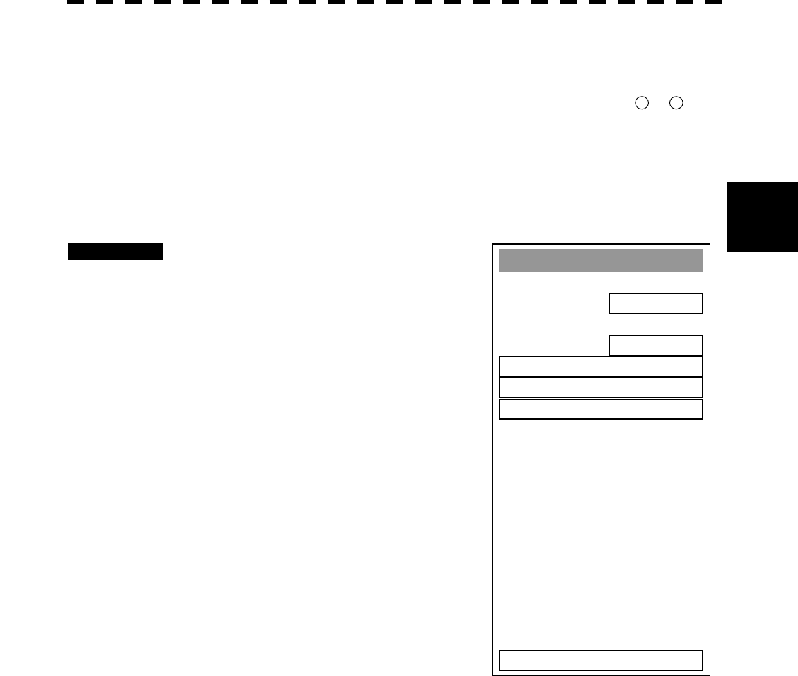
3─60
3
3.5 BASIC OPERATIONS
A
TA Guard Zone
1. Guard Zone 1
ON
2. Guard Zone 2
OFF
3. Make Guard
Z
one 1
5. ENT
0. EXIT
4. Make Guard Zone 2
3.5.19 Operation of Guard Zone [ATA Guard Zone]
A fan-shaped guard zone can be set to watch for other ships and targets to invade or to automatically
track other invading ships.
The guard zone function can be switched between ON and OFF by placing the cursor on 49 or 50 on the
radar display on page 2-7 and pressing [ENT]. In this case, the guard zone set previously will be ON.
[I] Making Guard Zone (Make Guard Zone 1/2)
Set a fan-shaped operation area of the guard zone.
Procedures 1 Press [ATA MENU] key.
Press [4] key.
Press [1] key.
The ATA Guard Zone Menu will appear.
2 Select the guide zone where you
want to make an area, pressing the
numeric key [3] to [4].
The Guard Zone selection mode is activated.
GUARD ZONE 1: [3] key
GUARD ZONE 2: [4] key
3 Using the [EBL] and [VRM] controls,
put the start position of the guard
zone at a desired position, and then
press ENT.
The start position of the guard zone will be
set.
4 Using the [EBL] and [VRM] controls,
put the end position of the guard
zone at a desired position, and then press ENT.
The end position of the guard zone will be set.
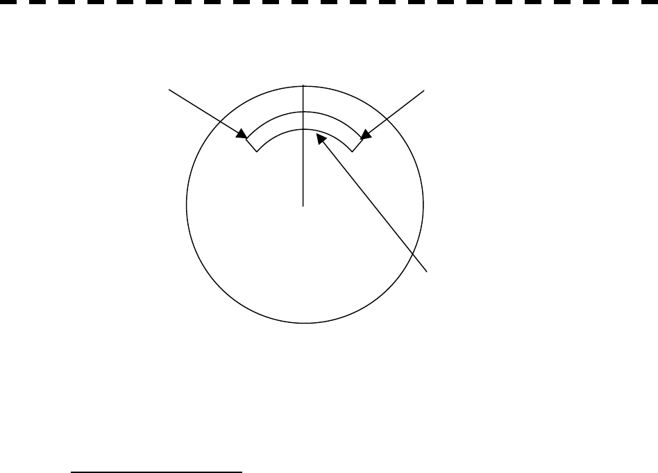
3─61
Attention Guard zones 1 and 2 can be set in the range of 0.5 to 32 nm.
The width of distance of the guard zone is fixed to 0.5 nm.
Operation of Guard zone
· If a target is found within the fan-shaped area of the guard zone, an alarm is generated and the▽mark
is displayed on the target. After approximately 1 minute, the tracking status is activated.
· If a guard zone is made, and the guard zone adopts the same point for the start point and end point, the
guard zone will be a circle.
· Guard zone is displayed only when radar transmission takes place.
Note that guard zone will not appear during preparation.
HL
Start point: Determined by the first [ENT] End point: Determined by the second [ENT]
Guard zone
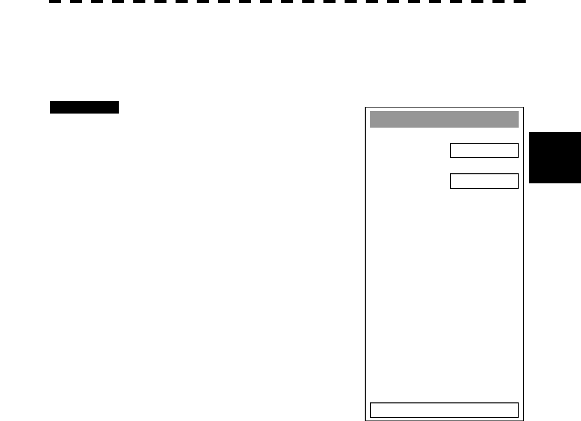
3─62
3
3.5 BASIC OPERATIONS
Guard Zone
1. Guard Zone 1
ON
2. Guard Zone 2
OFF
0. EXIT
[II] Set [GZALARM] key (Set GZ Alarm key)
Set a guard zone that is turned ON/OFF when the [GZ ALARM] key is pressed.
Such a guard zone can be simply called by assigning this key to a guard zone to be used on a steady
basis.
Procedures 1 Press [ATA MENU] key.
Press [4] key.
Press [3] key.
Press [1] key.
The Guard Zone Menu will appear.
2 Pressing [1] or [2], set the operation to
be performed with the [GZ ALARM]
key pressed.
GUARD ZONE1: [1] key is used for operation.
ON: Each time the [GZ ALARM] key
is pressed, guard zone 1 is turned
ON/OFF.
OFF: If the [GZ ALARM] key is
pressed, guard zone 1 is not turned
ON/OFF.
GUARD ZONE2: [2] key is used for operation.
ON: Each time the [GZ ALARM] key
is pressed, guard zone 2 is turned
ON/OFF.
OFF: If the [GZ ALARM] key is
pressed, guard zone 2 is not turned
ON/OFF.

3─63
RADAR Alarm
1. Sector RADAR Alarm >
3. Make Sector Alarm >
5. Radar Alarm Mode
IN
6. Sensitivity Level
4
0. EXIT
3.5.20 Radar Alarm (Radar Alarm)
With a fan-shaped range made, the radar alarm can give an alarm to ships that invade or depart from the
range.
[I] Set Radar Alarm Mode (Radar Alarm Mode)
For alarm issuing conditions for the radar alarm, set either entry or departure.
Procedures 1 Press [ATA MENU] key.
The ATA Menu will appear.
2 Press [4] key.
Press [2] key.
The Radar Alarm Menu will appear.
3 Press [5] key.
The radar alarm mode will be switched between
ON and OFF.
IN: Issues an alarm when ship enters.
OUT: Issues an alarm when ship departs.
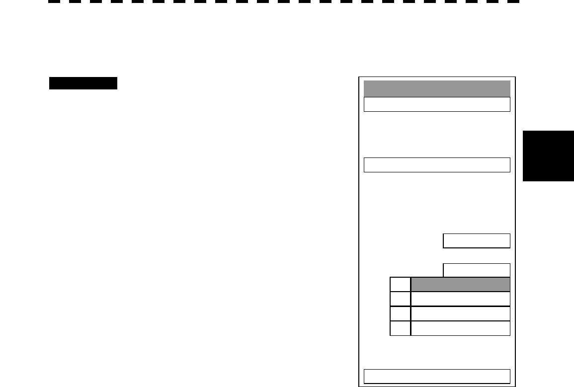
3─64
3
3.5 BASIC OPERATIONS
RADAR Alarm
1. Sector RADAR Alarm >
3. Make Sector Alarm >
5. Radar Alarm Mode
IN
6. Sensitivity Level
4
0. EXIT
1. 1
2. 2
3. 3
4. 4
[II] Set Radar Alarm Detection Level (Sensitivity Level)
Detection levels can be set to issue alarms from the radar alarm.
Procedures 1 Press [ATA MENU] key.
The ATA Menu will appear.
2 Press [4] key.
Press [2] key.
The Radar Alarm Menu will appear.
3 Press [6] key.
When a detection level appears, select the
number you want to set, pressing the numeric
keys [1] to [4].
* As the numeric value for detection level is
larger, echo needs to be stronger for detection.
If the numeric value for detection level is low,
detection can be made with weak echo to
issue an alarm.
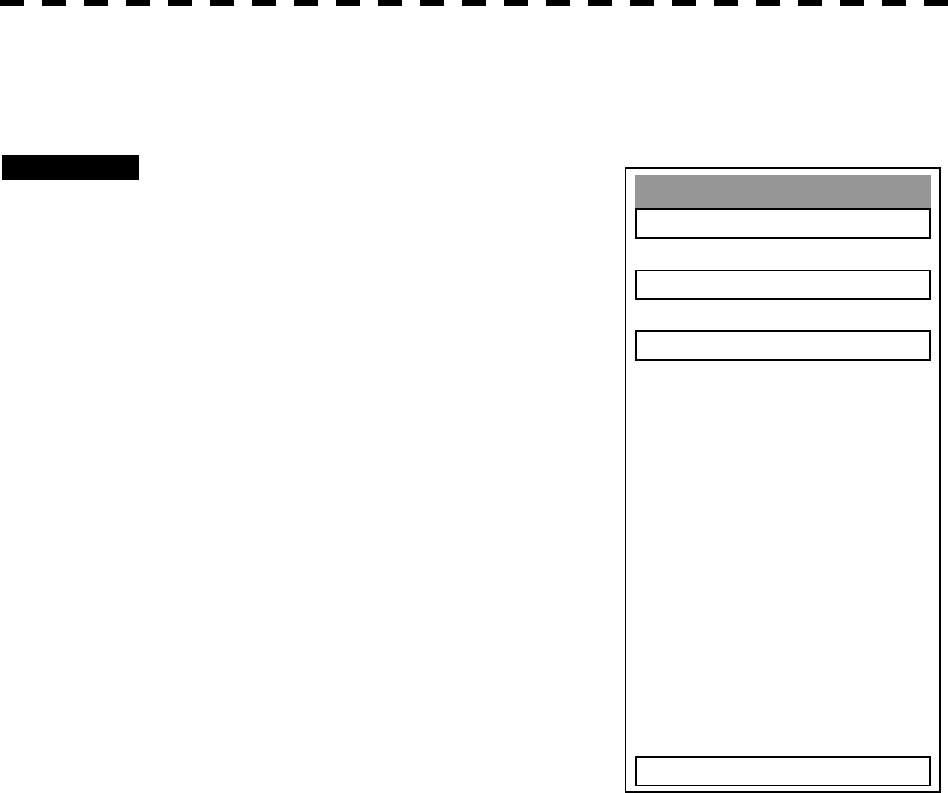
3─65
Make Sctor Alarm
1. Sector Alarm 1
2. Sector Alarm 2
3. ENT
0. EXIT
[III] Make Sector Alarm (Make Sector Alarm)
Sector alarms that can be made are divided into the two types.
Procedures 1 Press [ATA MENU] key.
The ATA Menu will appear.
2 Press [4] key.
Press [2] key.
The Radar Alarm Menu will appear.
3 Press [3] key.
The Make Sector Alarm Menu will appear.
4 Press numeric key [1] or [2] in
accordance with the Sector Alarm to
be made.
5 Place the start position of the sector
alarm at a desired position by
operating the EBL/VRM dial, and then
select ENT.
The start position of the Sector Alarm will be
set.
6 Place the end position of the Sector
Alarm at a desired position by
operating the EBL/VRM dial, and then select ENT.
The end position of the Sector Alarm will be set.

3─66
3
3.5 BASIC OPERATIONS
Sector RADAR Alarm
1. Sector Alarm 1
ON
2. Sector Alarm 2
ON
[IV] Display Sector Alarm (Sector Alarm 1, 2)
Display a created Sector Alarm.
Procedures 1 Press [ATA MENU] key.
The ATA Menu will appear.
2 Press [4] key.
Press [2] key.
The Radar Alarm Menu will appear.
3 Press [1] key.
The Sector Radar Alarm Menu will appear.
4 Press numeric key [1] or [2] in
accordance with the Sector Alarm to
be displayed.
The display sector alarm mode will be
switched between ON and OFF.
ON: Displayed
OFF : Not displayed
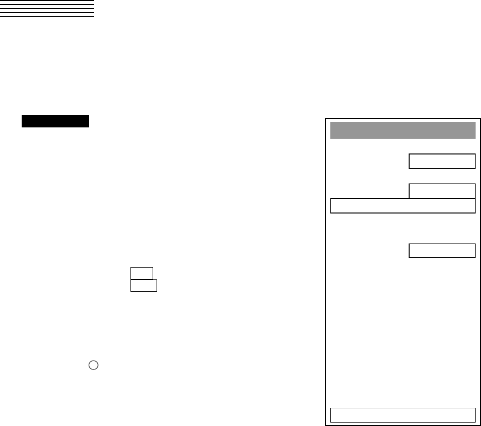
3─67
3.6 DISPLAY OWN SHIP’S TRACK
3.6.1 Display Own Ship’s Track (Display Own Track)
If navigation equipment is connected, this system records data received from the navigation equipment and
displays the own ship’s track.
Procedures 1 Press [RADAR MENU] key twice.
Press [9] key.
Press [1] key.
The Own Track Setting Menu will appear.
2 Press [2] key.
The setting of Display Own Track will be
switched between ON and OFF.
ON : The own ship’s track is displayed.
OFF : The own ship’s track is not displayed.
* Button 28 on the radar display on page 2-7 is also available to
switch the Display Own Track between ON and OFF.
Note: The own ship’s track can be displayed even while Own Track Memory is set to OFF. In this
case, if rewrite operation such as changing of the display range is performed for the radar
display, the own ship’s track display is erased and the track is not plotted again.
If DISP Own Track is set to OFF when Own Track Memory is ON, the own ship’s track is not
shown on the radar display but the system stores own ship’s track data at specified intervals.
Own Track Settin
g
1. Own Track Interval
1 min
2. Display Own Track
ON
3. Clear Own Track
4. Own Track Memory
ON
0. EXIT
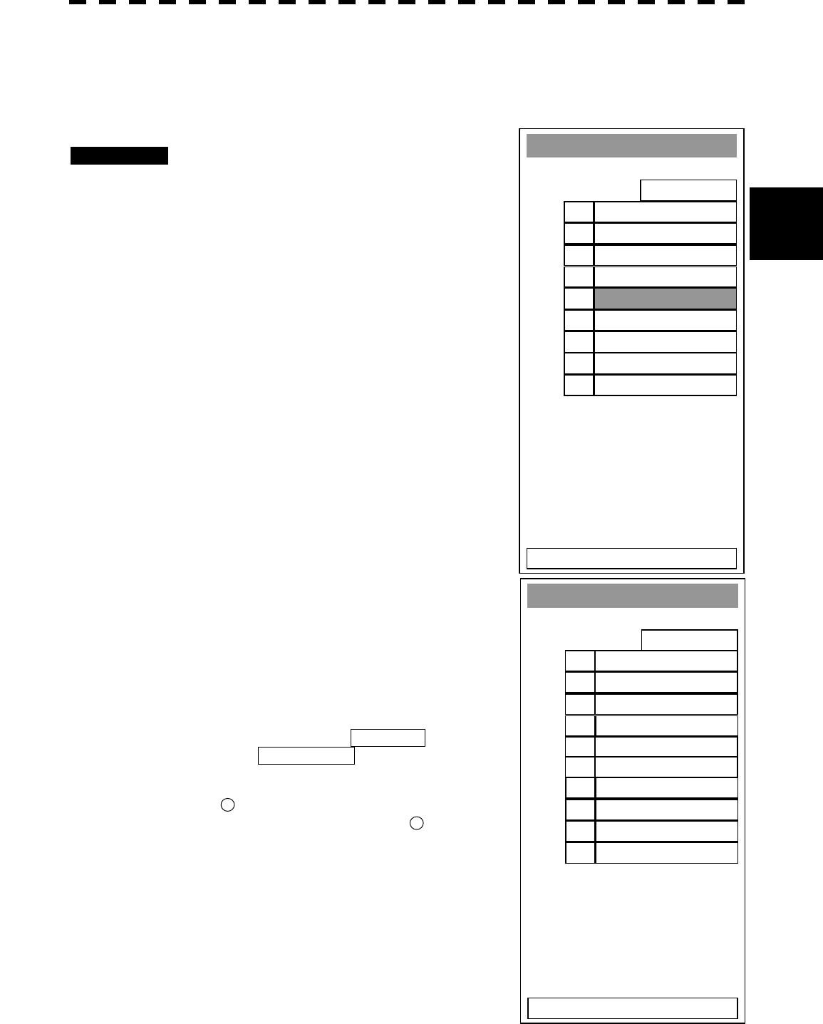
3─68
3
3.6 DISPLAY OWN SHIP’S TRAC
K
3.6.2 Set Own Ship’s Track Data Storage Interval (Own Track Interval)
There are 10 preset time intervals and 4 preset range intervals that can be selected for storing own ship’s track
data.
Procedures 1 Press [RADAR MENU] key twice.
Press [9] key.
Press [1] key.
The Own Track Setting Menu will appear.
2 Press [1] key.
The Own Track Interval Setting Menu will
appear.
3 Select the storage interval number to
be set, pressing the numeric key.
The selected storage interval will be set.
A preset time interval or preset distance interval can be selected
as the storage interval.
Storage intervals that can be selected
Time: 3 sec, 5 sec, 10 sec, 30 sec, 1 min, 3 min, 5 min, 10
min, 30 min, and 60 min
Range: 1 nm, 3 nm, 5 nm, and 10 nm
The pull-down menu consists of 2 pages.
To switch between the pages, select Next Page pressing the
numeric key [9], or Previous Page pressing the numeric key
[0].
* Pressing button 41 on the radar display on page 2-7, you can
switch track data storage intervals, and pressing 42 button on the
radar display on page 2-7, you can switch of a memory unit.
Setting the button to OFF cancels the storing of data.
Own Track Settin
g
1. Own Track Interval
1 min
2. DISP Own TRK Color
A
LL
3. CLR Own TRK Color
WHITE
4. Own TRK Memory
OFF
0. EXIT
3 sec1.
5 sec2.
10 sec3.
30 sec4.
1 min5.
3 min6.
5 min7.
10 min8.
Next Pa
g
e9.
Own Track Settin
g
1. Own Track Interval
1 min
2. DISP Own TRK Colour
A
LL
3. CLR Own TRK Colour
WHITE
4. Own TRK Memory
OFF
0. EXIT
30 min1.
60 min2.
1 nm3.
3 nm4.
5 nm5.
10 nm6.
7.
8.
9.
Previous Pa
g
e0.
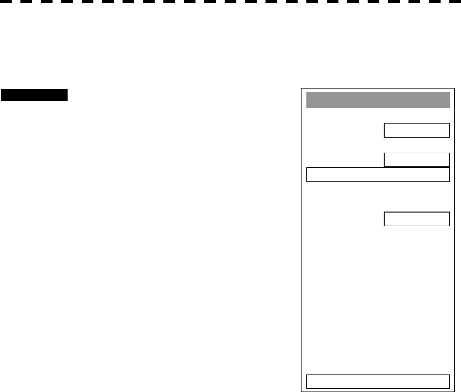
3─69
3.6.3 Clear Own Ship’s Track Data (Clear Own Track)
This function clears own ship’s track data from memory.
Procedures 1 Press [RADAR MENU] key twice.
Press [9] key.
Press [1] key.
The Own Track Setting Menu will appear.
2 Press [3] key.
The Clear Own Track Confirmation Menu will
appear.
3 Press [1] key.
The own ship’s track data will be cleared.
Own Track Settin
g
1. Own Track Interval
1 min
2. Display Own Track
ON
3. Clear Own Track
4. Own Track Memory
ON
0. EXIT

3─70
3
3.6 DISPLAY OWN SHIP’S TRAC
K
3.6.4 Cancel Storing of Own Ship’s Track Data (Own Track Memory)
This function cancels the storing of own ship’s track data.
Procedures 1 Press [RADAR MENU] key twice.
Press [9] key.
Press [1] key.
The Own Track Setting Menu will appear.
2 Press [4] key.
The setting of Own Track Memory will be
switched between ON and OFF.
ON : Own ship’s track data is stored.
OFF : Own ship’s track data is not stored.
* Button 41 on the radar display on page 2-7 is also available for
switching Track Data Storage Intervals. Setting the button to OFF cancels own track memory.
Note: The own ship’s track can be displayed even while Own Track Memory is set to OFF. In this
case, if rewrite operation such as changing of the display range is performed for the radar
display, the own ship’s track display is erased and the track is not plotted again.
If Display Own Track is set to OFF when Own Track Memory is ON, the own ship’s track is not
shown on the radar display but the system stores own ship’s track data at specified intervals.
Own Track Settin
g
1. Own Track Interval
1 min
2. Display Own Track
ON
3. Clear Own Track
4. Own Track Memory
ON
0. EXIT
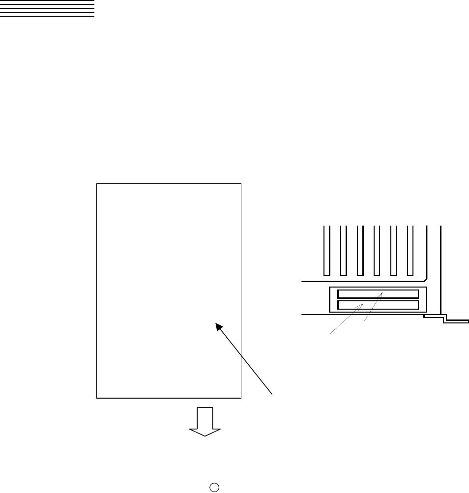
3─71
3.7 DISPLAY CHARTS
3.7.1 Display Coastline ROM Card Produced by JRC
l Insert the Coastline ROM card produced by JRC with the top surface upward into card slot 1 (lower)
or 2 (upper) as shown in the figure below. Press [MAP] key, and the coastlines will be displayed
automatically.
l Two Coastline ROM cards can be inserted into card slots 1 and 2 at the same time.
l For ranges including detailed coastlines, refer to the Coastline ROM card catalog.
l Do not insert an ERC card (provided by Japan Hydrographic Association) or C-MAP card into a card
slot while JRC’s Coastline ROM card is in the other slot. Doing so causes display trouble.
処理部前面
上段:カードスロット2
下段:カードスロット1
* Insert the card and then press button 30 on the radar display on page 2-7 to switch Display Charts between
ON and OFF.
JRC
CDD-612JKA
Coastline ROM Card
Area: Kanto and Tokai Districts
(1) Kanto
Japan Radio Co., Ltd.
Top surface
Insert into card slot 1 or 2.
Front view of the processor
Upper: Card slot 2
Lower: Card slot 1
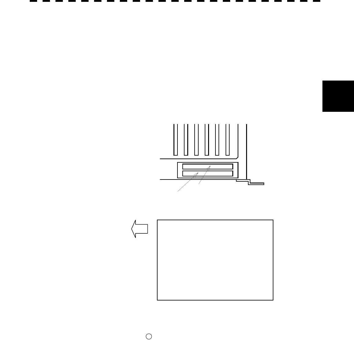
3─72
3
3.7 DISPLAY CHART
3.7.2 Display ERC Card
l Insert the ERC card (provided by Japan Hydrographic Association) with the top surface upward into
card slot 1 (lower) or 2 (upper) as shown in the figure below. Press [MAP] key, and the coastlines will
be displayed automatically.
l Two ERC cards can be inserted into card slots 1 and 2 at the same time.
l For ranges of charts to be displayed, refer to the catalog issued by Japan Hydrographic Association.
l Do not insert JRC’s Coastline ROM card or C-MAP card into a card slot while the ERC card is in the
other slot. Doing so causes display trouble.
処理部前面
上段:カードスロット2
下段:カードスロット1
* Insert the card and then press button 30 on the radar display on page 2-7 to switch Display Charts between
ON and OFF.
Electronic Reference Charts for Navigation
R-300 Tokyo Bay and Vicinity
★North of Tokyo Bay
★Uraga Channel and Vicinity
★South of Tokyo Bay – Ohshima
★Taitohsaki - Irohzaki
Front view of the processor
Upper: Card slot 2
Lower: Card slot 1
Insert into card slot 1 or 2.
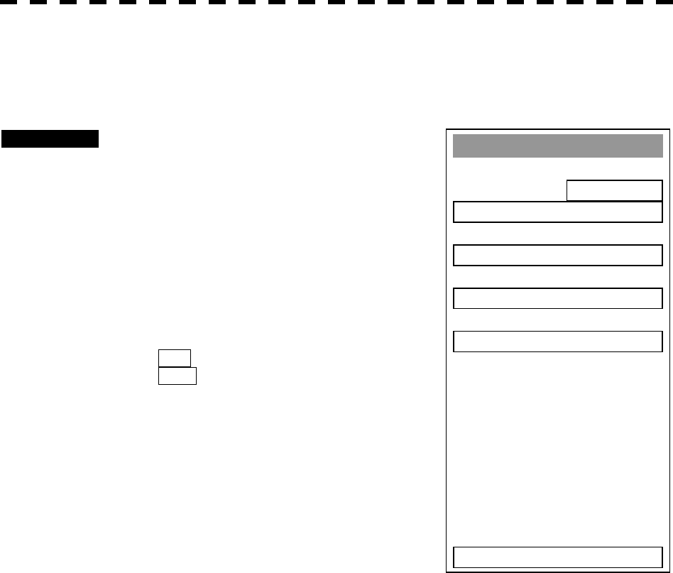
3─73
3.7.3 Fill Charts (Fill Land Area)
This function fills the chart when JRC/ERC card is in use.
Procedures 1 Press [RADAR MENU] key twice.
Press [9] key.
Press [5] key.
The Map Setting Menu will appear.
2 Press [1] key.
The setting of Fill Land Area will be switched
between ON and OFF.
ON : Charts are filled.
OFF : Charts are not filled.
Map Settin
g
1. Fill Land Area
ON
2.
C
-MAP Settin
g
3. JRC/ERC Card Settin
g
4. Contour Settin
g
5. Map Display Settin
g
0. EXIT
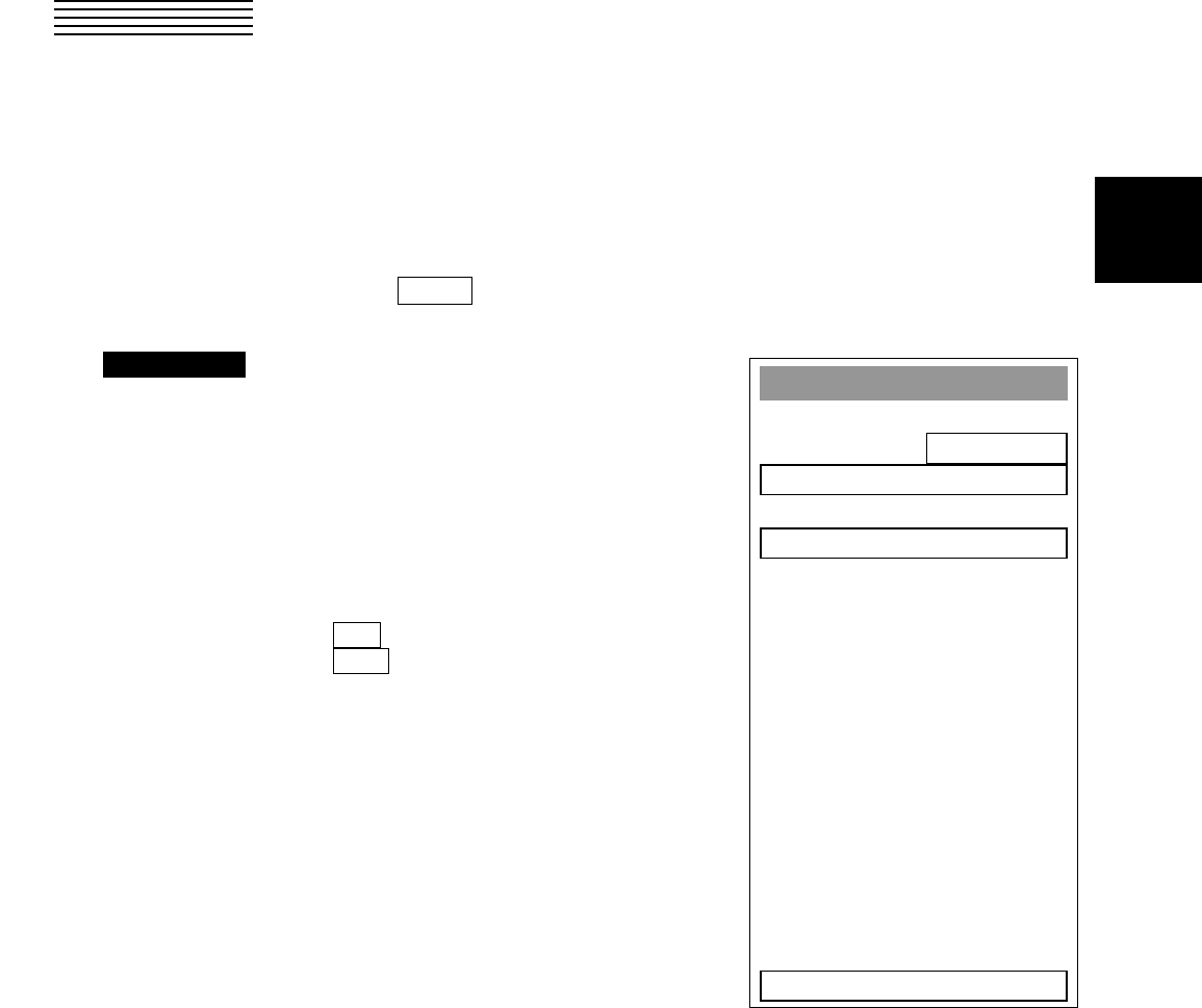
3─74
3
3.8 DISPLAY NAVIGATION INFORMATION
Navigation information such as waypoint marks, and a maximum of 256 points of NAV lines, coastlines, depth
contours, and NAV marks can be displayed, created, read, saved, corrected, and deleted. (This function is
available only when navigation equipment is connected with the system.)
3.8.1 Display Waypoint Marks (Waypoint Display)
When waypoint information is received from the navigation equipment, the waypoint mark appears on the
radar display. In this case, ○WP is indicated as the waypoint mark on the radar display.
Procedures 1 Press [RADAR MENU] key twice.
Press [6] key.
The NAV Information Menu will appear.
2 Press [1] key.
The setting of Waypoint Display will be
switched between ON and OFF.
ON : Displays waypoint marks.
OFF : Does not display waypoint marks.
Waypoint marks are displayed only when NMEA sentences are used to receive Waypoint
information. A plotter function (option) is needed to make Waypoint in this radar.
NAV Information
1. Waypoint Display
ON
2. NAV Display Settin
g
>
3. User Map Settin
g
>
4. Geodetic
WGS-8400
0. EXIT
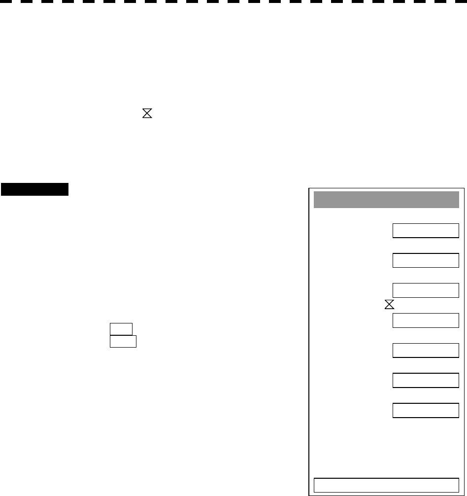
3─75
3.8.2 Display Navigation Information (NAV Display Setting)
The navigation information below can be displayed (ON) or hidden (OFF) individually.
NAV lines [NAV Line] ―
Coastlines [Coast Line] ----
Depth contours [Contour] ‐―
Mark 1 [Mark 1]
Mark 2 [Mark 2] ★
Mark 3 [Mark 3] +
Mark 4 [Mark 4] Y
Procedures 1 Press [RADAR MENU] key.
Press [6] key.
Press [2] key.
The NAV Display Setting Menu will appear.
To determine whether to display each type of
navigation information, press the corresponding
numeric key.
ON : Displays the navigation information.
OFF : Does not display the navigation
information.
NAV Display Settin
g
1. NAV Line ―
ON
2. Coast Line ----
ON
3. Contour ‐―
ON
4. Mark1
ON
5. Mark2 ★
ON
6. Mark3 +
ON
7. Mark4 Y
ON
0. EXIT
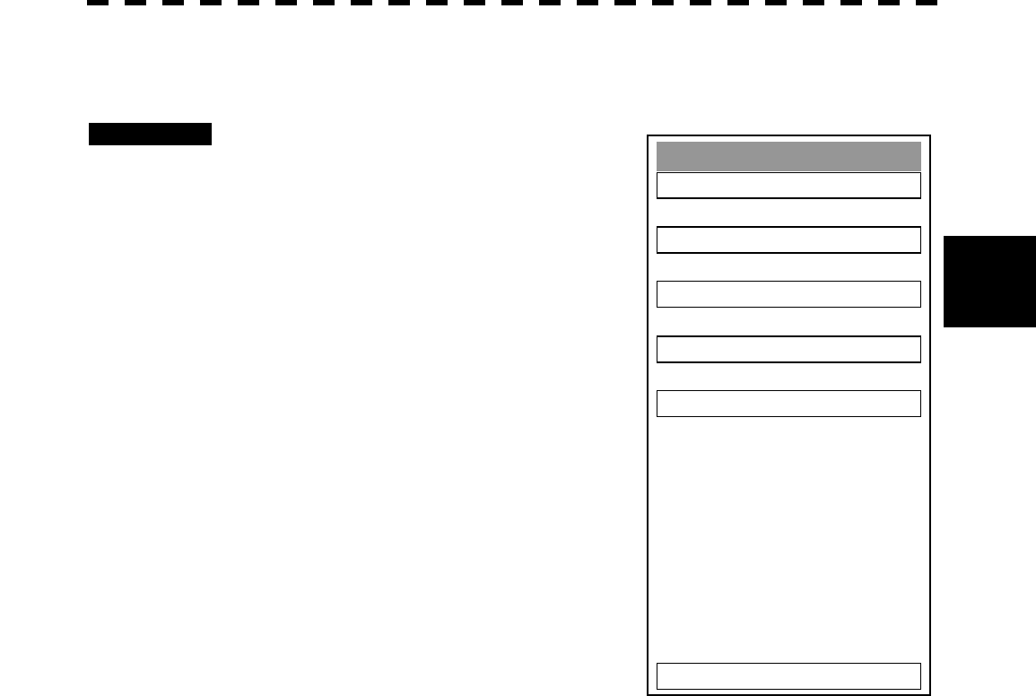
3─76
3
3.8 DISPLAY NAVIGATION INFORMATION
3.8.3 Create/Edit Navigation Information (Edit User Map)
Procedures 1 Press [RADAR MENU] key.
Press [6] key.
Press [3] key.
Press [6] key.
The Edit User Map Menu will appear.
The Edit User Map enables the operations of
the functions below.
Clear Map Object: Clears all or an item of
navigation information.
Make Map Object: Creates navigation
information.
Correct: Corrects navigation information.
Delete: Deletes one point from navigation
information.
Insert: Inserts an element into a line of each
type
Edit User Map
1. Clear Map Ob
j
ect >
2. Make Map Object >
3. Correct
4. Delete
5. Insert
0. EXIT
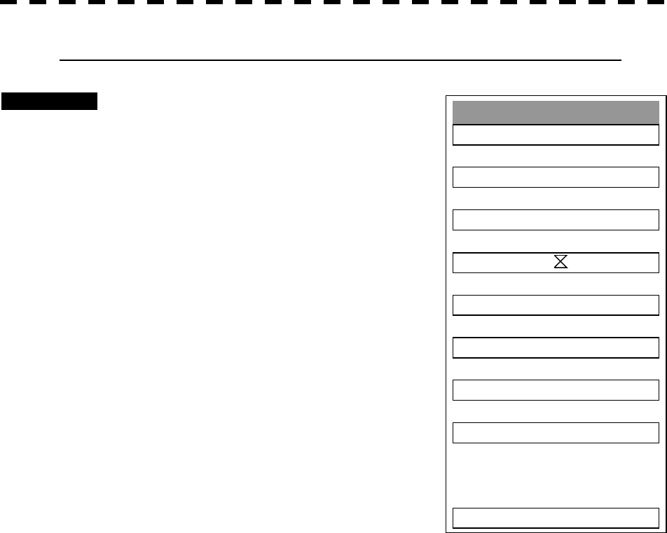
3─77
1 Clearing all or an item of navigation information (Clear Map Object)
Procedures 1 Press [1] key while the Edit User MAP
Menu is open.
The Clear Map Object Menu will appear.
Select the type of navigation information to be
cleared, pressing the corresponding numeric key.
NAV Line: Clears NAV lines.
Coast Line: Clears coastlines.
Contour: Clears contour lines.
Mark1: Clears Mark 1.
Mark2: Clears Mark 2.
Mark3: Clears Mark 3.
Mark4: Clears Mark 4.
All: Clears all items of navigation information.
Clear Map Ob
j
ect
1. NAV Line ―
2. Coast Line ----
3. Contour ‐―
4. Mark1
5. Mark2 ★
6. Mark3 +
7. Mark4 Y
8. All
0. EXIT
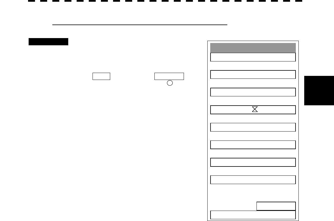
3─78
3
3.8 DISPLAY NAVIGATION INFORMATION
2 Making navigation information (Make Map Object)
Procedures 1 Press [2] key while the Edit User MAP
Menu is open.
The Make Map Object Menu will appear.
MAKE will appear in the CURSOR mode
field at the radar display button 19 .
2 Select the type of navigation
information to be made, pressing the
corresponding numeric key.
3 Use the trackball to move the cross
cursor mark to the starting point of a
line or a point where a mark is to be
made, and press [ENT] key.
The starting point of a line or one point of a
mark will be determined.
4 Repeat step 3, and press [8] key
when finishing the making of the line
or mark.
The line or mark make mode will terminate.
5 To make another line or mark, repeat
steps 2 to 4.
6 Press [0] key when finishing the making of all navigation information.
The Edit User Map Menu will reappear.
Note: Navigation information can be created with a maximum of 256 points being plotted.
The number of points that can still be plotted (REMAIN POINT in the menu) is decremented
each time a line or mark is plotted.
Make Map Ob
j
ect
1. NAV Line ―
2. Coast Line ----
3. Contour ‐―
4. Mark1
5. Mark2 ★
6. Mark3 +
7. Mark4 Y
8. ENTE
R
Remain Point
256
0. EXIT
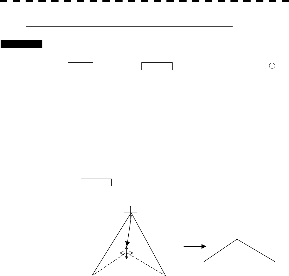
3─79
3 Correcting a continuous line or moving a mark (Correct)
Procedures 1 Press [3] key while the Edit User Map Menu is open.
The navigation information correction mode will be activated.
Correct will appear in the CURSOR mode field at the radar display button 19 .
2 Use the trackball to move the pointer to the vertex in a line to be
corrected or the mark to be moved, and press [ENT] key.
The cross cursor mark will appear on the selected line or mark.
3 Use the trackball to move the cross cursor mark to a new point to which
the line is corrected or the mark is moved.
The selected line will be corrected to the new point, or the mark will be moved there.
4 To correct another line or mark, repeat steps 2 and 3.
5 Press [3] key when finishing the correction of lines and marks.
The CURSOR mode at the upper right of the radar display will change to the general
operation mode, terminating the navigation information correction mode.
(Example)
Select a top
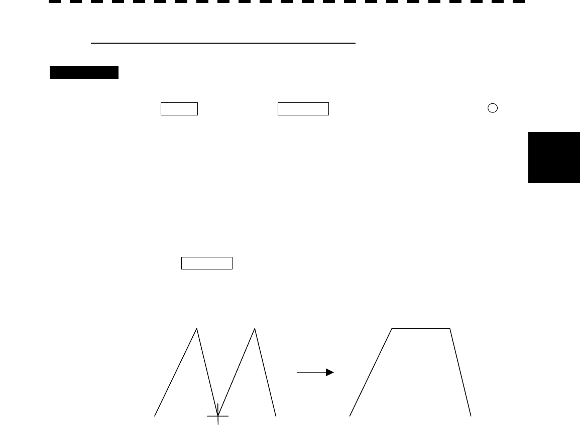
3─80
3
3.8 DISPLAY NAVIGATION INFORMATION
4 Deleting a continuous line or mark (Delete)
Procedures 1 Press [4] key while the Edit User Map Menu is open.
The navigation information deletion mode will be activated.
Delete will appear in the CURSOR mode field at the radar display button 19 .
2 Use the trackball to move the pointer to the vertex in a line or the mark
to be deleted, and press [ENT] key.
The selected line or mark will be deleted.
Note: A line drawn by joining two points is all deleted.
3 To delete another line or mark, repeat step 2.
4 Press [0] key when finishing the deletion of lines and marks.
The CURSOR mode at the upper right of the radar display will change to the general
operation mode, terminating the navigation information deletion mode.
(Example) Deletion of a vertex from a line
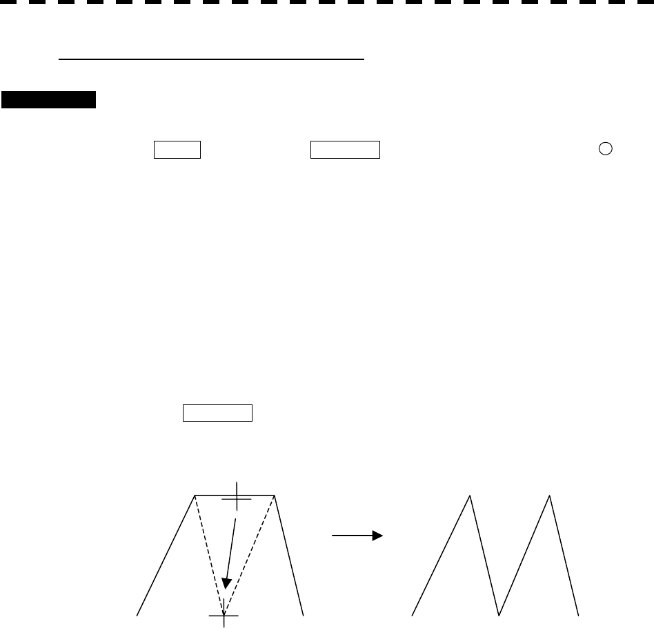
3─81
5 Inserting a vertex into a line (Insert)
Procedures 1 Press [5] key while the Edit User MAP Menu is open.
The navigation information insertion mode will be activated.
Insert will appear in the CURSOR mode field at the radar display button 19 .
2 Use the trackball to move the pointer to the line that is to become a
vertex, and press [ENT] key.
The cross cursor mark will appear on the selected point.
3 Use the trackball to move the cross cursor mark to a new point where a
vertex is to be formed, and press [ENT] key.
A vertex will be inserted into the selected line.
4 To insert another vertex, repeat steps 2 and 3.
5 Press [0] key when finishing the insertion of all vertices.
The CURSOR mode at the upper right of the radar display will change to the general
operation mode, terminating the navigation information insertion mode.
(Example)
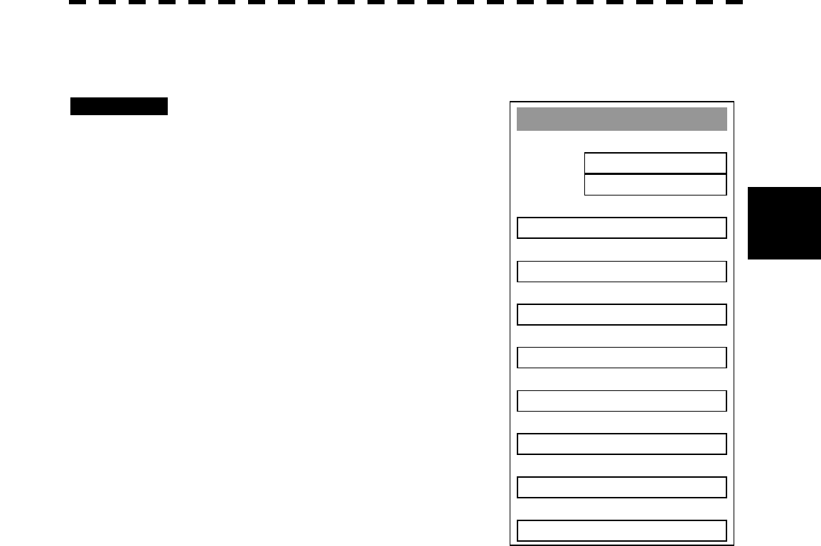
3─82
3
3.8 DISPLAY NAVIGATION INFORMATION
3.8.4 Set Navigation Information (User Map Setting)
Procedures 1 Press [RADAR MENU] key.
Press [6] key.
Press [3] key.
The User Map Setting Menu will appear.
Select operation for navigation information,
pressing the corresponding numeric key. The
selected operation will be performed.
Load: Loads navigation information.
Unload: Unloads navigation information.
Save: Saves navigation information.
Erase: Erases navigation information.
Edit User Map:Edits navigation information.
Shift: Shifts the display position of
navigation information.
Shift Clear: Clears position correction
information.
User Map Settin
g
1. Own Ship Position
N 35°23.000’
E139°22.345’
2. Load >
3. Unload
4. Save >
5. Erase >
6. Edit User Map >
7. Shift
8. Shift Clear
0. EXIT

3─83
[I] Entering the own ship’s position in manual mode (Own Ship Position)
Use this function to edit the navigation information of any positions other than the own ship’s position.
Procedures 1 Press [1] key while the User Map Setting Menu is open.
The CODE INPUT Menu for entering latitude and longitude of the own ship position will
appear.
2 Enter a value as the latitude (xx° xxx.xx’) using the numeric keys [0] to
[9].
3 To switch between north latitude and south latitude, turn the [MULTI]
control.
Each time the control is turned, N (north latitude) is changed to S (south latitude), or vice
versa.
4 Press [ENT] key.
The latitude entered in manual mode will be determined.
Subsequently, enter the longitude.
5 Enter a value as the longitude (xx° xxx.xx’) using the numeric keys [0] to
[9].
6 To switch between east longitude and west longitude, turn the [MULTI]
control.
Each time the control is turned, E (east longitude) is changed to W (west longitude), or
vice versa.
7 Press [ENT] key.
The longitude entered in manual mode will be determined.
* Button on the CODE INPUT Menu is also available instead of the numeric keys.
Note: The own ship’s position manually entered by using the function above is valid only in the User
MAP Setting Menu. When control exits from the menu, the manually entered position data is
invalidated.
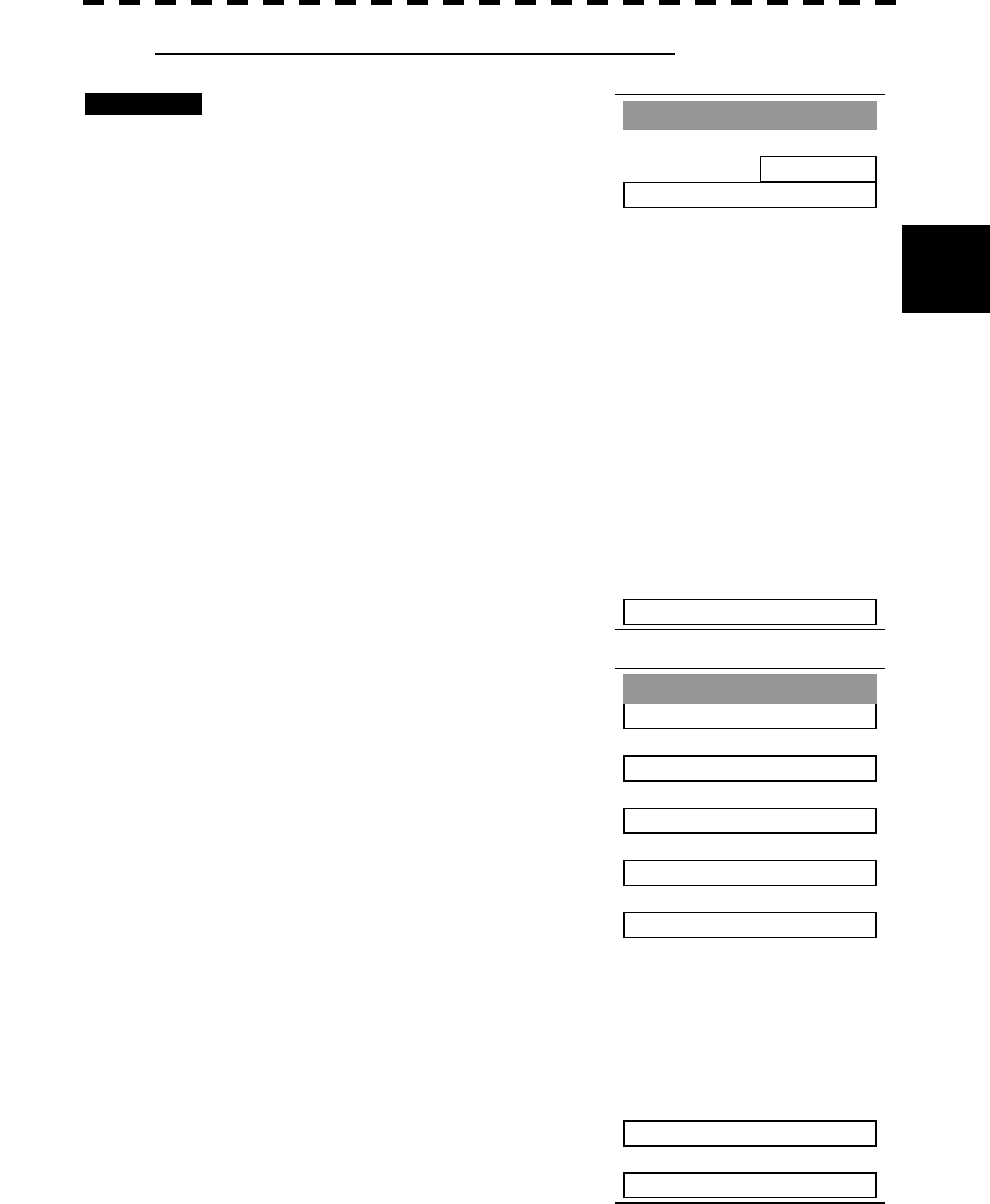
3─84
3
3.8 DISPLAY NAVIGATION INFORMATION
[II] Loading navigation information (Load User Map)
Procedures 1 Press [2] key while the User Map
Setting Menu is open.
The Load User Map Menu will appear.
2 Press [2] key.
The list of navigation information files saved
in the system will appear.
* Each time you press [1] key, the Device item is switched between
INTERNAL and CARD2.
INTERNAL: Reads saved data from the processor.
CARD2: Reads saved data from CARD2.
To select CARD2, insert the flash memory card, in which data has
been saved, into card slot 2 (upper stage).
3 Select the number of the file to be
loaded, pressing the numeric key.
The selected navigation information will be
loaded and shown on the radar display.
Load User Map
1. TOKYO
2. OSAK
A
3. SENDAI
4. NEW YOR
K
5. SEATLE
9. Next Pa
g
e
0. EXIT
Load User Map
1. Device
INTERNAL
2. Load User MAP >
0. EXIT
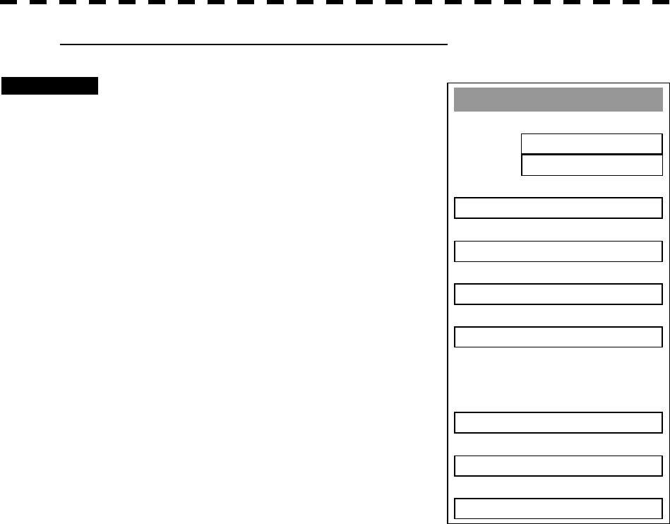
3─85
User MAP Settin
g
1. Own Ship Position
35°23.000’ N
139°22.345’ E
2. Load >
3. Unload
4. Save >
5. Erase >
7. Shift
8. Shift Clear
0. EXIT
[III] Initializing Navigation Information (Unload)
Procedures 1 Press [3] key while the User Map
Setting Menu is open.
Display the window to select whether or not the
information is to be initialized.
2 Press [1] key.
The navigation information is initialized.
This function can be executed for files that have
been read and new navigation information currently
being entered.
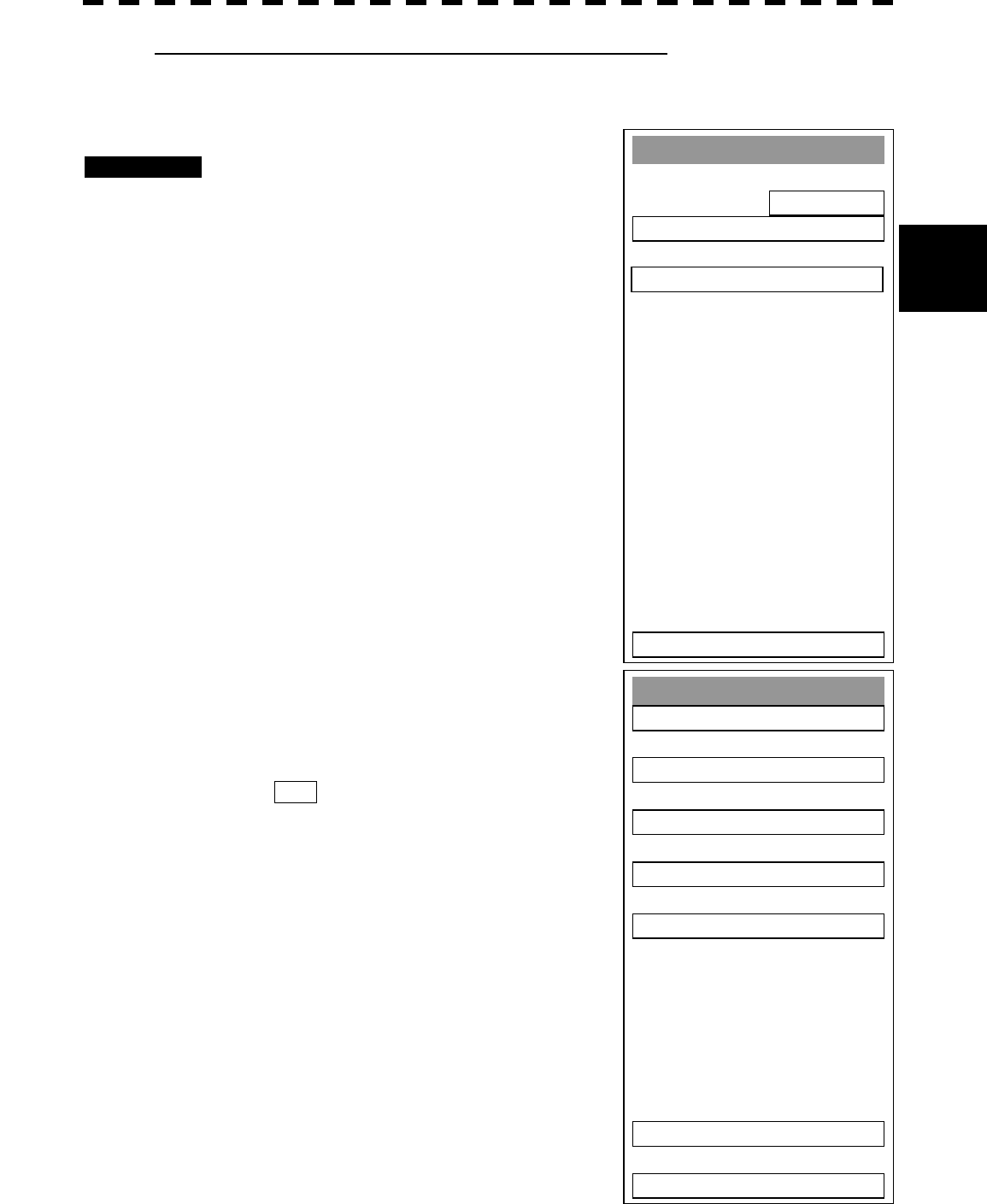
3─86
3
3.8 DISPLAY NAVIGATION INFORMATION
[IV] Saving navigation information (Save User Map)
This function is available only when navigation equipment is connected with the system or the own
ship’s position is entered in manual mode.
Procedures 1 Press [4] key while the User Map
Setting Menu is open.
2 Press [2] key.
The Save User Map Menu will appear.
* Each time you press [1] key, the Device item is switched between
INTERNAL and CARD2.
INTERNAL: Saves data in the processor.
CARD2: Saves data in CARD2.
To select CARD2, insert the flash memory card, in which data has
been saved, into card slot 2 (upper stage).
3 Select the number of the file to be
saved, pressing the numeric key.
The Name Input Menu will appear.
4 Use the trackball to select an
alphabetic character A-Z or 0-9 shown
in the menu and press [ENT] key on
your required characters.
A maximum of 10 characters can be entered.
5 Repeat step 4 until the file name to be
saved is created, move the cursor to
ENT , and press [ENT] key.
The currently displayed navigation information
will be saved.
Save User Map
1. TOKYO
2. OSAK
A
3. SENDAI
4. NEW YOR
K
5. SEATLE
9. Next Pa
g
e
0. EXIT
Save User Map
1. Device
INTERNAL
2. Save User MAP >
0. EXIT
3.
A
ll Files to Card 2 >
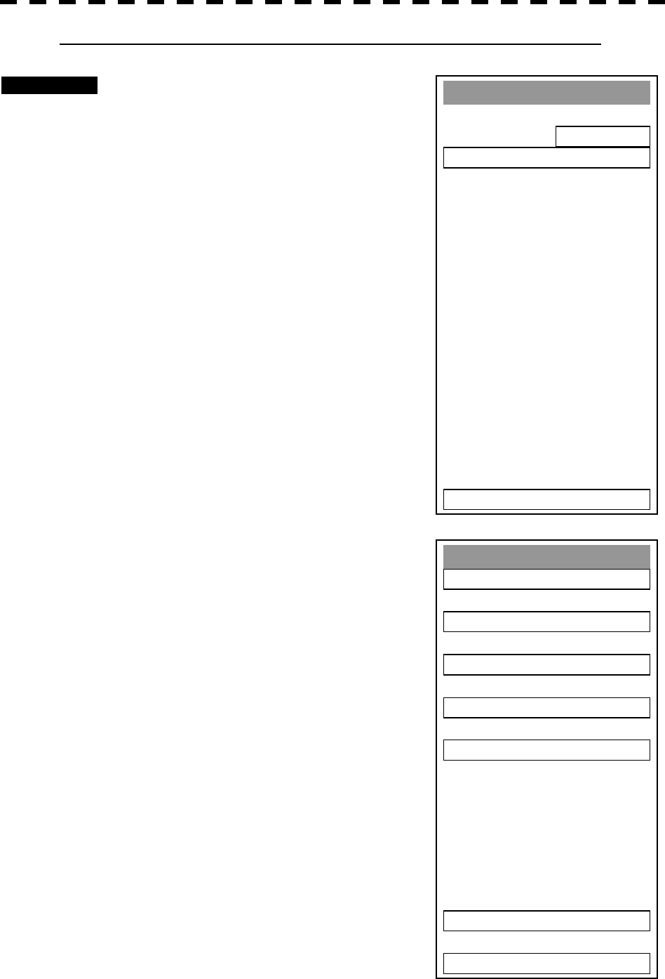
3─87
Erase User Map
1. TOKYO
2. OSAK
A
3. SENDAI
4. NEW YOR
K
5. SEATLE
9. Next Pa
g
e
0. EXIT
[V] Erasing navigation information from memory (Erase User Map)
Procedures 1 Press [5] key while the User Map
Setting Menu is open.
2 Press [2] key.
The Erase User Map Menu will appear.
* Each time you press [1] key, the Device item is switched between
INTERNAL and CARD2.
INTERNAL: Erases saved data from the processor.
CARD2: Erases saved data from CARD2.
To select CARD2, insert the flash memory card, in which data has
been saved, into card slot 2 (upper stage).
3 Select the number of the file you want
to erase, pressing the numeric keys
[1] to [5].
The navigation information file will be erased
from the memory, and the file name will
disappear from the file list.
Erase User Map
1. Device
INTERNAL
2. Erase User MAP >
0. EXIT
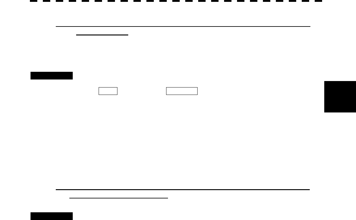
3─88
3
3.8 DISPLAY NAVIGATION INFORMATION
[VI] Shifting the display position of navigation information to a correct
position (Shift)
If the display position of navigation information is incorrect, it can be shifted to the correct position in
manual mode.
Procedures 1 Press [7] key while the User Map Setting Menu is open.
Shift will appear in the CURSOR mode field at the upper right of the radar display,
and the navigation information shift mode is activated.
2 Use the trackball to move the pointer to a mark or a point on a NAV line,
coastline, or depth contour line, and press [ENT] key.
3 Use the trackball to move the cross cursor mark to the position to which
the mark or line is shifted, and press [ENT] key.
All the marks and lines currently displayed will be shifted to their correct positions.
[VII] Shifting the corrected display position of navigation information
back to original (Shift Clear)
Procedures 1 Press [8] key while the User Map Setting Menu is open.
Only the latest display position correction information (for a single operation) will be
cleared, and the navigation information is displayed at the original position.
Note: Only the latest correction information is cleared, and correction information older than that
cannot be cleared any more.
Once operation such as creation, move, deletion, insertion, or batch deletion is done after the
correction of a navigation information display position, the latest correction information cannot
be restored to original any more.
3─89
3.8.5 Set and Display Geodetic System
To create navigation information, set the geodetic system that is used with the connected navigation equipment.
When navigation information is loaded, the geodetic system used when the navigation information was saved,
is displayed. Make sure that the displayed geodetic system is identical to the one used with the navigation
equipment. If the two geodetic systems are different, the positions of navigation information on the radar
display will be shifted. Therefore, it is important to set the geodetic system of the navigation equipment.
Procedures 1 Press [RADAR MENU] key.
Press [6] key.
The NAV Information Menu will appear.
2 Press [4] key.
The geodetic system input ten-key screen will
appear.
3 Enter the number of the target
geodetic system, pressing the
numeric keys.
4 The entered geodetic system number
can be changed by turning the
[MULTI] control.
5 Press [ENT] key.
The entered geodetic system will be
determined.
NAV Information
1. Way Point Display
ON
2. NAV Display Setting >
3. User Map Settin
g
>
4. Geodetic
WGS-8400
0. EXIT

3─90
3
3.8 DISPLAY NAVIGATION INFORMATION
Geodetic System List
No. Name
0 WGS-84
1 WGS-72
2 Japan
3 North American 1927(U.S)
4 North American 1927(Canada & Alaska)
5 European 1950 (Europe)
6 Australian geodetic 1966 (Australia)
7 Ordance Survery of Great Britain (England)
8 NAD-83
9 - (No Use)
10 - (No Use)
11 ADINDAN (Etiopia & Sudan)
12 ARC 1950 (Botswana)
13 AUSTRALIAN GEODETIC 1984 (Australia)
14 BERMUDA 1957 (the Bermudas)
15 BOGOTA OBSERVATORY (Columbia)
16 CAMPO INCHAUSPE
17 CHATHAM 1971
18 CHUAASTRO (Paraguay)
19 CORREGO ALEGRE (Brazil)
20 DJAKARTA (VATAVIA) (Sumata)
21 EUROPEAN 1979 (Europe)
22 GEODETIC DATUM 1949 (New Zeland)
23 GUAM 1963 (Guam)
24 HAYFORD 1910 (Finland)
25 HJORSEY 1955 (Ice land)
26 INDIAN (India & Nepal)
27 IRELAND1965 (Ireland)
28 KERTAU 1948 (West Malaysia)
29 L.C.5 ASTRO (Cayman Black Island)
30 LIBERIA 1964 (Liberia)
31 LUZON (Philippines)
32 MERCHICH (Morocco)
33 MINNA (Cameroon)
34 NAHRWAN (Oman)
35 NAPARIMA, BWI (Trinidad & Tobago)
36 OLD EGYPTIAN (Egypt)
37 OLD HAWAIIAN (Hawaii)
38 PCO DE LAS NIEVES (Canary)
39 PROVISIONAL SOUTH AMERICAN 1956 (South America)
40 PROVISIONAL SOUTH CHILEAN 1963 (South Chile)
41 PUERTO RICO (Puerto Rico & Virgin Islands)
42 QORNOQ (South Greenland)
43 RT90 (Sweden)
44 SANTA BRAZ (San Miguel island & Saint Mary islands)
45 SOUTH AMERICAN 1969 (South America)
46 SOUTHWEST BASE (Faial & Sao Jorge & Pico & Graciosa & Terceira island)
47 TIMBALAI 1948 (Brunei & East Malaysia)
48 - (No Use)
49 - (No Use)
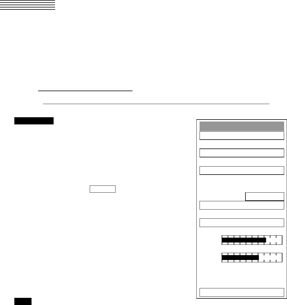
3─91
3.9 OPERATE PERFORMANCE MONITOR
(PM DISPLAY)
3.9.1 Operation Procedures
This function is available only when the radar equipment is equipped with the NJU-63/64 Performance
Monitor.
1 Preparation for Operation
If the equipment is provided with a radar interswitch, set the interswitch to the Master Radar mode.
Procedures 1 Press [RADAR MENU] key twice.
Press [8] key.
Press [9] key.
The Test Menu will appear.
2 Press [4] key.
The TX LVL indicator bar-graph in the menu
indicates the performance monitor status. Use
this bar graph to check for the transmitted power.
(The following are automatically set for the
radar:
Relative motion (RM)
OFF CENTER OFF
IR OFF
PROCESS OFF
TGT ENH OFF
FUNCTION OFF, and
24 NM range
At the same time, the PM pattern for checking
the receiver system is shown on the radar
display.)
Exit 1 Press [RADAR MENU] key.
The Test Menu will be closed.
Notes: · When PM is set to ON, all target acquisitions by ARPA functions are cancelled.
Once the target acquisitions are cancelled, they are not recovered.
· The radar image is suppressed for the operator to easily view the PM image. Thus, be sure to
close the TEST MENU when having checked for the PM.
Test Menu
1. Self Test
2. Monitor Test
3. Panel Test
4. PM Display
ON
5. Error Lo
gg
in
g
6. System INFO
MAGI
T
XLVL
0. EXIT
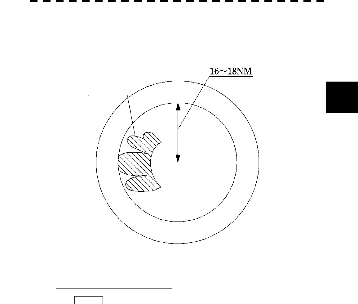
3─92
3
3.9 OPERATE PERFORMANCE MONITOR
2 Checking Transmitter System
The TX LVL indicator bar-graph in the menu indicates the value corresponding to the transmitted
power. If the currently indicated bar is extremely shorter than when initially checked, the transmitter
system needs to be inspected by the service engineer.
PM pattern
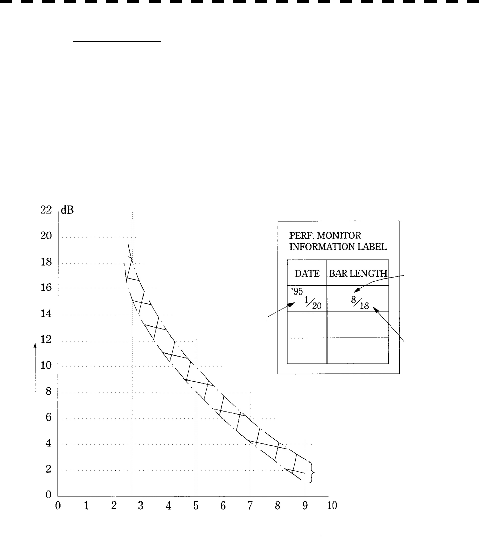
3─93
Check Procedure
Read the value A of the current bar length.
Referring to the Calibration Curve I, obtain the relative attenuation d (B) for the
initial bar length B shown on the INFORMATION LABEL.
Referring to the Calibration Curve I, obtain the relative attenuation d (A) for the value
A. The result of d (A) - d (B) indicates the current attenuation of transmitted power
compared with the initially specified value.
When d (A) - d (B) indicates attenuation of 10 dB or more (due to the end of
magnetron’s life), the transmitter system needs to be inspected by the service
engineer.
Figure 1
Calibration Curve I
Relative Attenuation d
Date and time of
initial setting
Initial bar length
Maximum range of
PM pattern
Measuring accuracy
Current Bar Length l
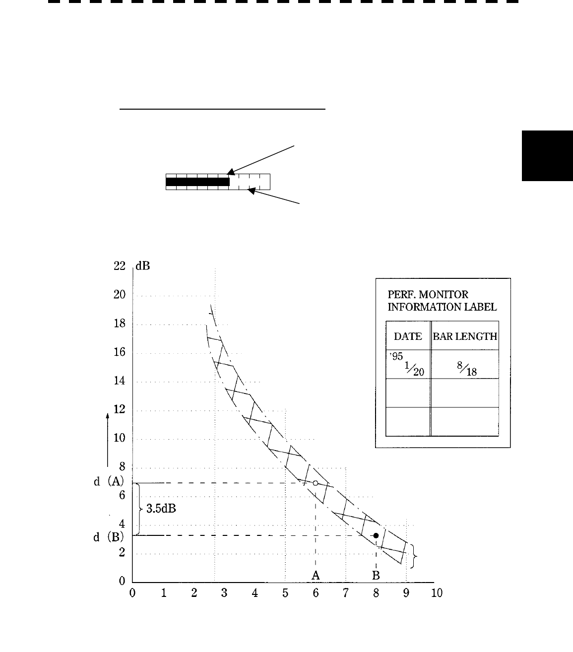
3─94
3
3.9 OPERATE PERFORMANCE MONITOR
(Example) When the initial bar length B = 8 and the current bar length A = 6, the relative attenuation is
obtained as d (B) = 3.5 dB and d (A) = 7 dB according to the Calibration Curve I. Thus, d
(A) - d (B) = 3.5 dB. This proves that the current attenuation of transmitted power is about
3.5 dB.
Example of Checking Transmitter System
Figure 2
T
XLVL
Current bar length A = 6
Initial bar length B = 8
Calibration Curve I
Relative Attenuation d
Measuring accuracy
Current Bar Length l
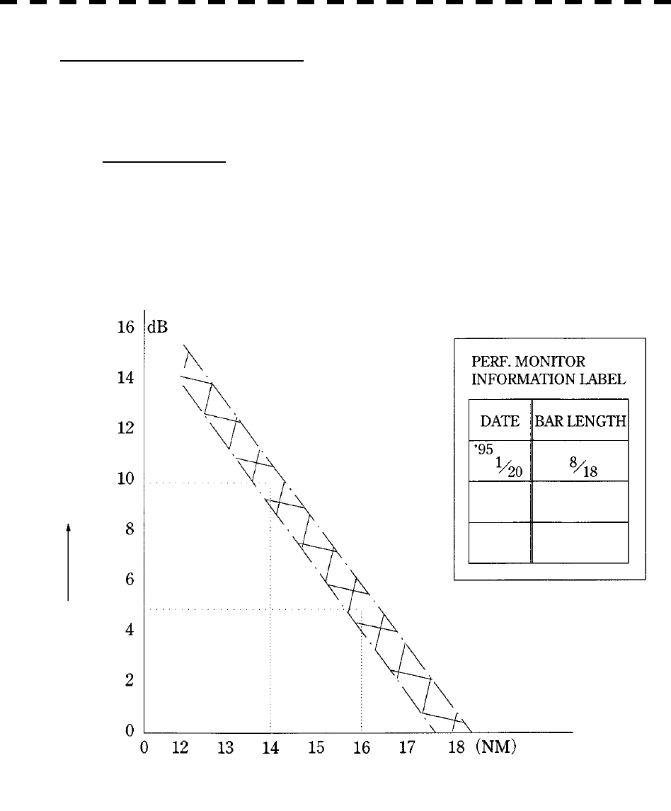
3─95
3 Checking Receiver System
The maximum range of the PM pattern on the display indicates that the receiver system’s sensitivity has
reduced.
Check Procedure
Measure the maximum range rmax from the PPI center to the PM pattern on the
display by using a VRM (Variable Range Marker).
Referring to the Calibration Curve II, obtain the reduction of sensitivity R (rmax).
The value R (rmax) indicates the current reduction of receiver system’s sensitivity.
Figure 3
Calibration Curve II
Reduction of Sensitivity R (rmax)
Maximum Range of PM Pattern (rmax)
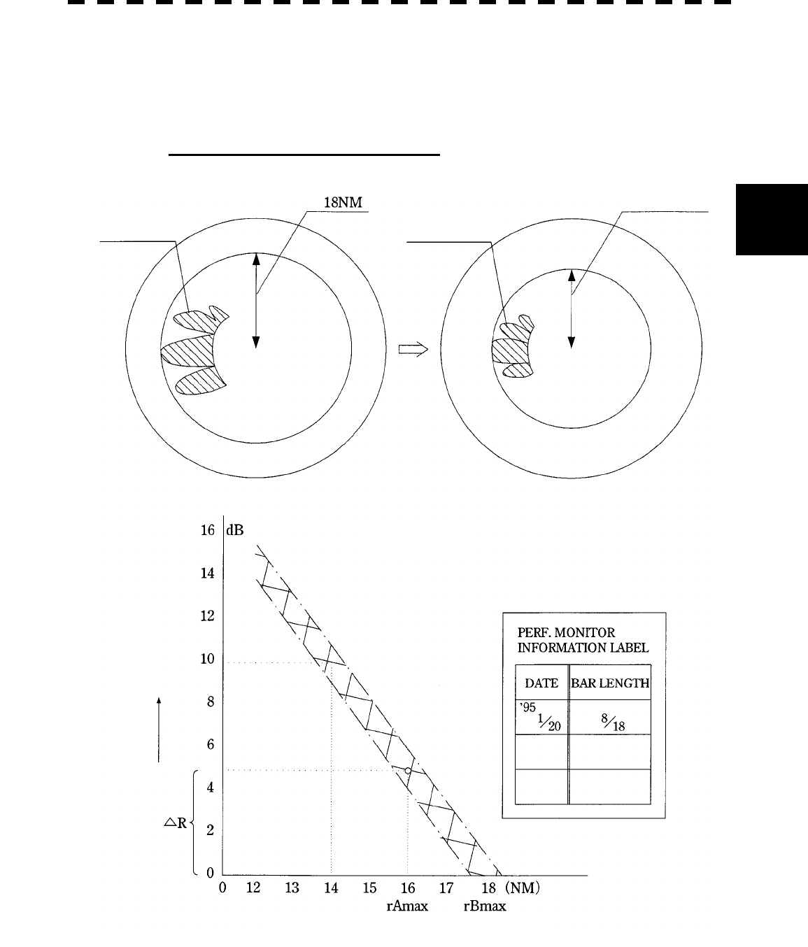
3─96
3
3.9 OPERATE PERFORMANCE MONITOR
(Example) When the maximum range of the initial PM pattern rBmax = 18 NM as shown on the
INFORMATION LABEL and the maximum range of the current PM pattern rAmax = 16
NM, the reduction of sensitivity DR (rmax) = 5 dB is obtained according to the Calibration
Curve II. This proves that the receiver system’s sensitivity has reduced by about 5 dB.
Example of Checking Receiver System
Figure 4
Calibration Curve II
Reduction of Sensitivity R (rmax)
Maximum Range of PM Pattern (rmax)
Initial PM pattern Current PM pattern
About 16 NM
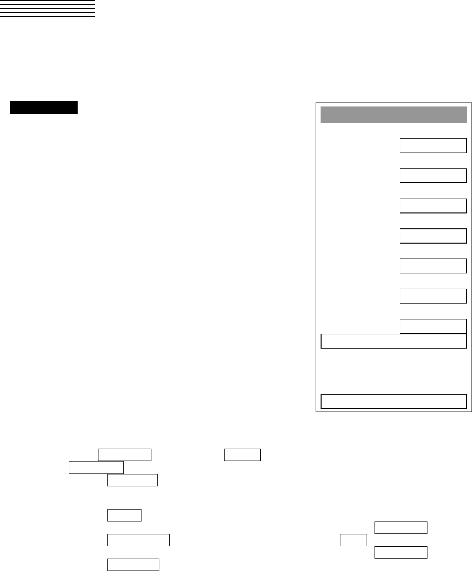
3─97
3.10 APPLIED OPERATIONS
3.10.1 Set Radar Signal Processing (Process Setting)
This function enables the setting of detail information about radar signal processing.
Procedures 1 Press [RADAR MENU] key twice.
Press [1] key.
The Process Setting Menu will appear.
Detail information about radar signal
processing can be set by changing the settings
of the menu items.
Note: After the settings for radar signal processing are
changed, small targets may not be displayed or
unwanted waves may not be suppressed. Thus, do
not make a significant change in the settings.
[1] Video Latitude
· Select the dynamic range in which receiving signals are to be shown on the radar display.
· Select NORMAL in standard, and WIDE in rainy weather.
· NARROW clearly displays short-range videos when STC is used in manual mode.
NORMAL : Standard setting
The dynamic range varies depending on the actual range:
Short range > long range
WIDE : Use this mode when rainy weather intensifies unwanted waves.
The dynamic range is about twice as wide as when NORMAL is selected.
SUPER WIDE : Use this mode when rain cloud remain at WIDE mode.
The dynamic range is about twice as wide as when NORMAL is selected.
NARROW : Narrows the dynamic range at short range.
Process Settin
g
1. Video Latitude
NORMAL
2. Video Noise Re
j
ection
LEVEL1
3. Auto DR Control
ON
4. Process Switch
OFF
5. 2nd Process Mode
REMAIN
6. Process Switch Ran
g
e
6.2nm
7. Fast Tar
g
et Detection
OFF
8. User Function Settin
g
0. EXIT

3─98
3
3.10
A
PPLIED OPERATIONS
[2] Video Noise Rejection
· This function rejects signals that assumed as noise and clutter in radar videos.
· Select OFF to display radar videos like analog signals.
· Select LEVEL1 or LEVEL2 to suppress noise and clutter.
· Select LEVEL1 or LEVEL2 to superimpose-display the chart.
OFF : Turns off the noise rejection function, and displays all signals.
Targets are popped up from noise and displayed like analog signals.
LEVEL1 : Rejects the signals of definitely unwanted waves (noise and clutter).
When detection of targets or unwanted waves is not definite, the signals are
displayed.
When detection of targets is definite, the signals are displayed.
LEVEL2 : Rejects the signals of definitely unwanted waves (noise and clutter).
When detection of targets or unwanted waves is not definite, the signals are
rejected.
Only when detection of targets is definite, the signals are displayed.
[3] Auto DR Control
· This function automatically controls the dynamic range of radar videos when the AUTO SEA/RAIN
clutter suppression mode is used.
· When the AUTO SEA clutter suppression mode is used, this function improves sensitivity by widening
the dynamic range of only areas where sea clutter is strong, and narrowing the dynamic range of areas
where sea clutter is not detected.
· When the AUTO RAIN clutter suppression mode is used, this function improves sensitivity by
widening the dynamic range of areas where sea clutter or rain/snow clutter is strong, and narrowing the
dynamic range of the other areas.
· Land videos become obscure when the AUTO RAIN clutter suppression mode is used.
OFF : Does not control the dynamic range automatically.
The dynamic range is set in the same manner as when the MANUAL
SEA/RAIN clutter suppression mode is used.
ON : Automatically controls the dynamic range. (Standard setting)
[4] Process Switch
· This function sets a specific area and switches the video process mode between the inside and outside
of the area.
· In [5] 2nd Process Mode, set the second video process mode for the area outside the boundary.
· In [2] PROCESS of Main Menu , set the first video process mode for the area inside the boundary.
· Sensitivity at a distance can be improved by suppressing near sea clutter through the correlative
process.
· There are two methods for setting an area:
OFF : Disables the Process Switching function. (Standard setting)
RANGE FIX : Sets a boundary at a constant range from the center.
Set the boundary range in [6] Process Switch Range.
The specific area turns out to be a circle with the own ship’s position as
the center.
AUTO : Automatically sets a specific area.
The area subject to many clutter returns is inside the boundary, and the
area less subject to clutter returns is outside the boundary.

3─99
[5] 2nd Process Mode
· Set the second video process mode for the outside of a specific area.
· This function is enabled when RANGE FIX or AUTO is selected in [4] Process Switching.
Video process modes
PROC OFF Video process off: Select this mode in general.
3SCAN CORR Correlative process 1: Select this mode when many rain/snow clutter returns are
detected.
4SCAN CORR Correlative process 2: Select this mode to highlight targets while suppressing sea
clutter returns.
5SCAN CORR Correlative process 3: Select this mode to detect small targets hidden by sea clutter
returns.
REMAIN Video process 4: Select this mode when own ship yaws wildly.
PEAK HOLD Video process 5: Select this mode to detect small targets of which detection
probability is low.
[6] Process Switch Range
· Set the boundary range of a specific area.
· This function is enabled when RANGE FIX is selected in [4] Process Switch.
· The specific area turns out to be a circle with the own ship’s position as the center.
· The boundary range can be set in units of 0.1 nm, ranging 0.1 to 25.5 nm.
· After selecting PROC Switch Range, adjust the range using the [MULTI] control.
· When finishing the adjustment, press [ENT] key to determine the video process switching range.
[7] Fast Target Detection
· This function displays fast moving targets that are suppressed in scan-correlative process mode.
· This function is enabled when 3SCAN CORR , 4SCAN CORR , or 5SCAN CORR is selected
as the video process mode.
· If unwanted waves remain on the radar display, suppress them by using the [SEA], [RAIN], or
[GAIN] control, or adjusting the interference rejection mode.
OFF : Disables the Fast Target Detection function.
ON : Enables the Fast Target Detection function.
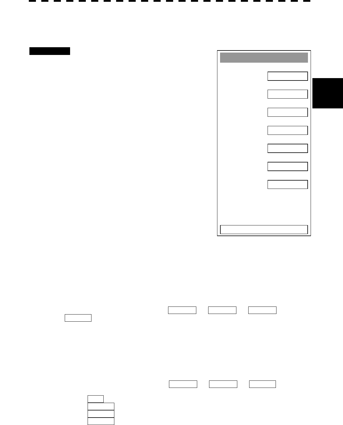
3─100
3
3.10
A
PPLIED OPERATIONS
3.10.2 Set Radar Trails (RADAR Trails Setting)
This function enables the setting of detail information about radar trails processing.
Procedures 1 Press [RADAR MENU] key twice.
Press [2] key.
The RADAR Tails Setting Menu will appear.
Detail information about radar trails processing
can be set by changing the settings of the menu
items.
Note: After the settings for radar trails processing are changed,
targets’ trails may not be displayed or trails may be plotted
with unwanted waves. Thus, do not make a significant
change in the settings.
[1] Trails Interval
· Set the trail intervals at which radar trails are displayed.
· Selection items of trail intervals change depending on the
setting of maximum value of radar trail display time.
· The Multi-function control is also available for setting.
· For the decision branches of trail interval, see Section 3.5.9
on page 3-45.
[2] Trails Mode
· Set the radar trail display mode.
· Each time the button is pressed, you can switch between True and Relative.
· For details on the trail mode, see Section 3.5.9 on page 3-45.
[3] Trails REF Level
· Select a radar video level required for plotting radar trails.
· The radar video level increases in order of LEVEL1 ® LEVEL2 ® LEVEL3 ®
LEVEL4 .
· To plot radar trails with unwanted waves, change to a higher level.
· To thin radar trails, change to a higher level.
· If radar trails are plotted in snatches, change to a lower level.
[4] Trails Reduction
· Make a setting for thinning radar trails.
· The effect of thinning increases in order of LEVEL1 ® LEVEL2 ® LEVEL3 .
· Radar videos do not become obscure because of the thinning of radar trails.
OFF : Disables the Trails Reduction function.
LEVEL1 : Enables the Trails Reduction function. (Effect: Low)
LEVEL2 : Enables the Trails Reduction function. (Effect: Modest)
LEVEL3 : Enables the Trails Reduction function. (Effect: High)
RADAR Trails Settin
g
1. Trails Interval
6 min
2. Trails Mode
TRUE
3. Trails REF Level
LEVEL2
4. Trails Reduction
OFF
5. Time/Cont Combine
OFF
6. Trails Process
OFF
7. Max Interval
SHORT
0. EXIT
3─101
[5] Time/Cont Combine
· This function superimpose-displays time radar trails and continuous radar trails.
· Operators can distinguish time radar trails from continuous radar trails by setting different colors for
both types of trails.
OFF : Disables the Time/Cont Combine function.
ON : Enables the Time/Cont Combine function.
[6] Trails Process
· Determine whether to use the video process with radar signals for plotting radar trails.
· When Trails Process is ON , radar trails are never plotted with unwanted waves, but the radar trails
of fast moving targets may not be plotted.
· When Trails Process is OFF , radar trails may be plotted with unwanted waves, but the radar trails of
fast moving targets are always plotted.
OFF : Disables the Trails Process function.
ON : Enables the Trails Process function.
[7] MAX Interval
· Select the maximum time for displaying radar trails.
· Select SHORT when short radar trails are often used in bays and the likes.
· Select LONG when long radar trails are necessary for ocean navigation.
· MEDIUM is for specification between SHORT and LONG .
· Continuous trails are available with all the options.
SHORT : Sets 15 minutes as the maximum time for radar trails display.
MEDIUM : Sets 30 minutes as the maximum time for radar trails display.
LONG : Sets 60 minutes as the maximum time for radar trails display.
SUPER LONG : Sets 12 hours as the maximum time for radar trails display.
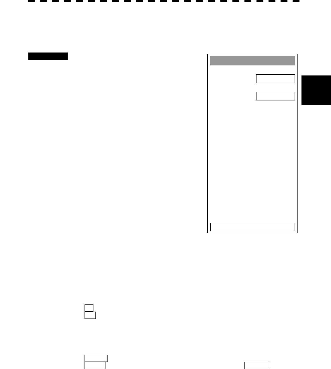
3─102
3
3.10
A
PPLIED OPERATIONS
3.10.3 Set Cursor (Cursor Setting)
This function enables the setting of detail information about cursor operation and display.
Procedures 1 Press [RADAR MENU] key twice.
Press [3] key.
Press [6] key.
The Cursor Setting Menu will appear.
Detail information about cursor operation and
display can be set by changing the settings of
the menu items.
[1] EBL/VRM Control CURS (device for cursor
operation)
· This function is switched between ON and OFF of EBL/VRM Control CRUS function
· The trackball is provided as a standard device. If the trackball malfunctions, the cursor can be moved
by using the [EBL] control and [VRM] control.
· The cursor moves horizontally when [EBL] is operated, and moves vertically when [VRM] is
operated.
· To switch between EBL/VRM operation and cursor operation while ON is selected, hold down the
[EBL] control for 2 seconds.
ON: Cursor is operated using a [EBL] [VRM] control.
OFF: Cursor is operated using a trackball.
[2] Cursor Length
· Set the length of the cross cursor mark on the radar display.
SHORT : Cuts the cross cursor mark in length.
LONG : Makes the cross cursor mark twice as long as when SHORT is selected.
Cursor Settin
g
1. EBL/VRM Control CURS
OFF
2. Cursor Len
g
th
LONG
0. EXIT
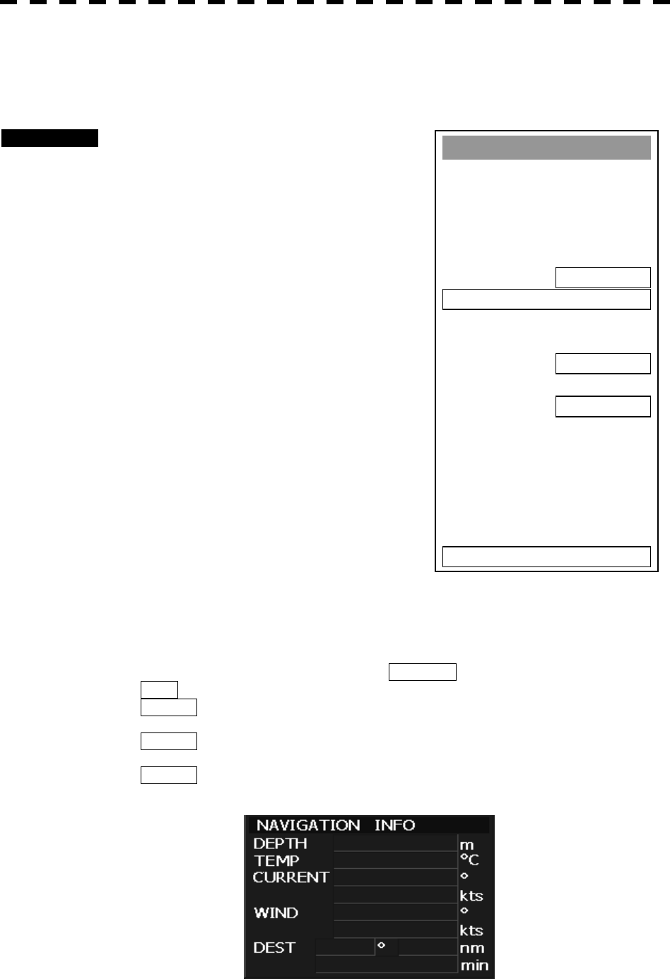
3─103
3.10.4 Set Screen(Screen Setting)
This function enables the setting of detail information about screen display.
Procedures 1 Press [RADAR MENU] key twice.
Press [4] key.
The Screen Setting Menu will appear.
Detail information about screen display can be
set by changing the settings of the menu
items.
[3] Numeric NAV INFO
· Determine whether to display the numeric values of
received navigation information.
· The values are displayed in one of three ATA/ARPA’s numeric data display areas.
· When the navigation information is displayed, the sizes of the ARPA’s numeric data display areas are
exclusively decreased.
· Navigation information of the water depth, water temperature, tidal current, wind direction/velocity,
and destination is displayed with numeric values.
· Numeric NAV INFO is set to ON/OFF each time the OPTION button on the screen is pressed.
OFF : Does not display the numeric values of navigation information.
AREA1 : Displays the numeric values of navigation information in numeric
data display area 1.
AREA2 : Displays the numeric values of navigation information in numeric
data display area 2.
AREA3 : Displays the numeric values of navigation information in numeric
data display area 3.
Screen Settin
g
1. Display Color Settin
g
2. Brilliance Settin
g
3. Numeric NAV INFO
OFF
4. Depth Graph Settin
g
5. Wind/Current Graph
OFF
6. DIR/DIST E
X
P Display
OFF
0. EXIT
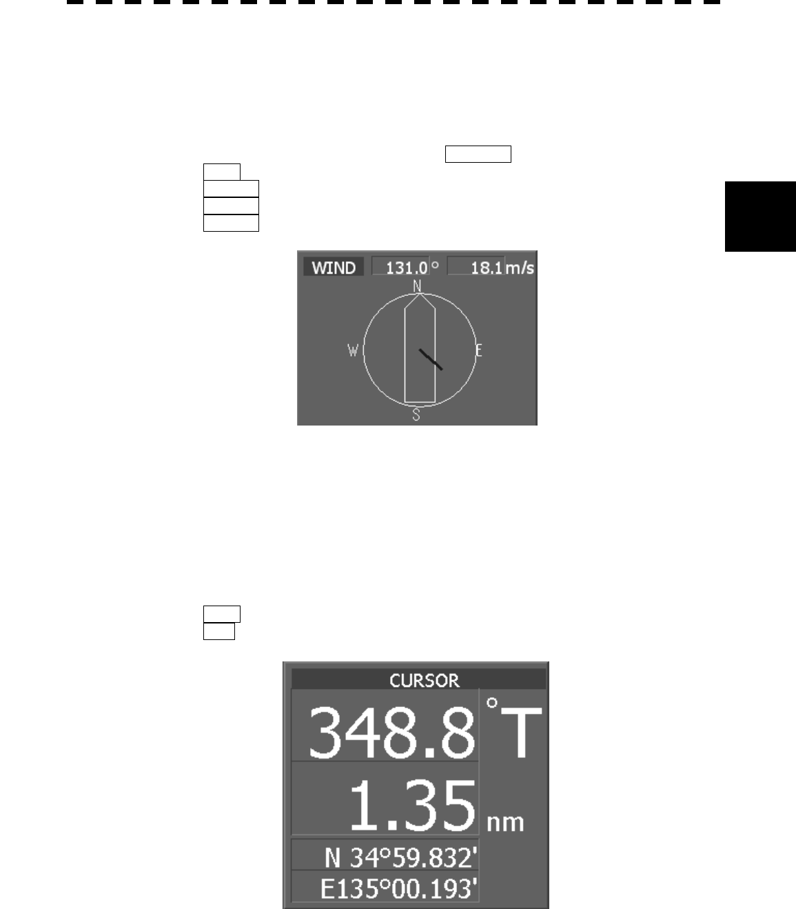
3─104
3
3.10
A
PPLIED OPERATIONS
[5] Wind/Current Graph
· Determine whether to display received wind direction/velocity information with a graph.
· The graph is displayed in one of three ATA/ARPA’s numeric data display areas.
· When the wind direction/velocity information is displayed, the sizes of the ATA/ARPA’s numeric data
display areas are exclusively decreased.
· Wind/Current Graph is set to ON/OFF each time the OPTION button on the screen is pressed.
OFF : Does not display the wind direction/velocity graph.
AREA1 : Displays the wind direction/velocity graph in numeric data display area 1.
AREA2 : Displays the wind direction/velocity graph in numeric data display area 2.
AREA3 : Displays the wind direction/velocity graph in numeric data display area 3.
[6] DIR/DIST EXP Display
· Determine whether to expand the value display of cursor, EBL, and VRM.
· The value display is expanded in ATA/ARPA’s numeric data display area 3.
· When the cursor mark moves on the PPI, the display of cursor information is expanded.
· When an EBL or VRM is operated, the value display of each marker is expanded.
· The expanded display remains for 5 seconds after the operation of each marker, and then it will
disappear.
· While the menu is open, any display is not expanded.
OFF : Does not expand any display.
ON : Expands the display in numeric data display area 3.
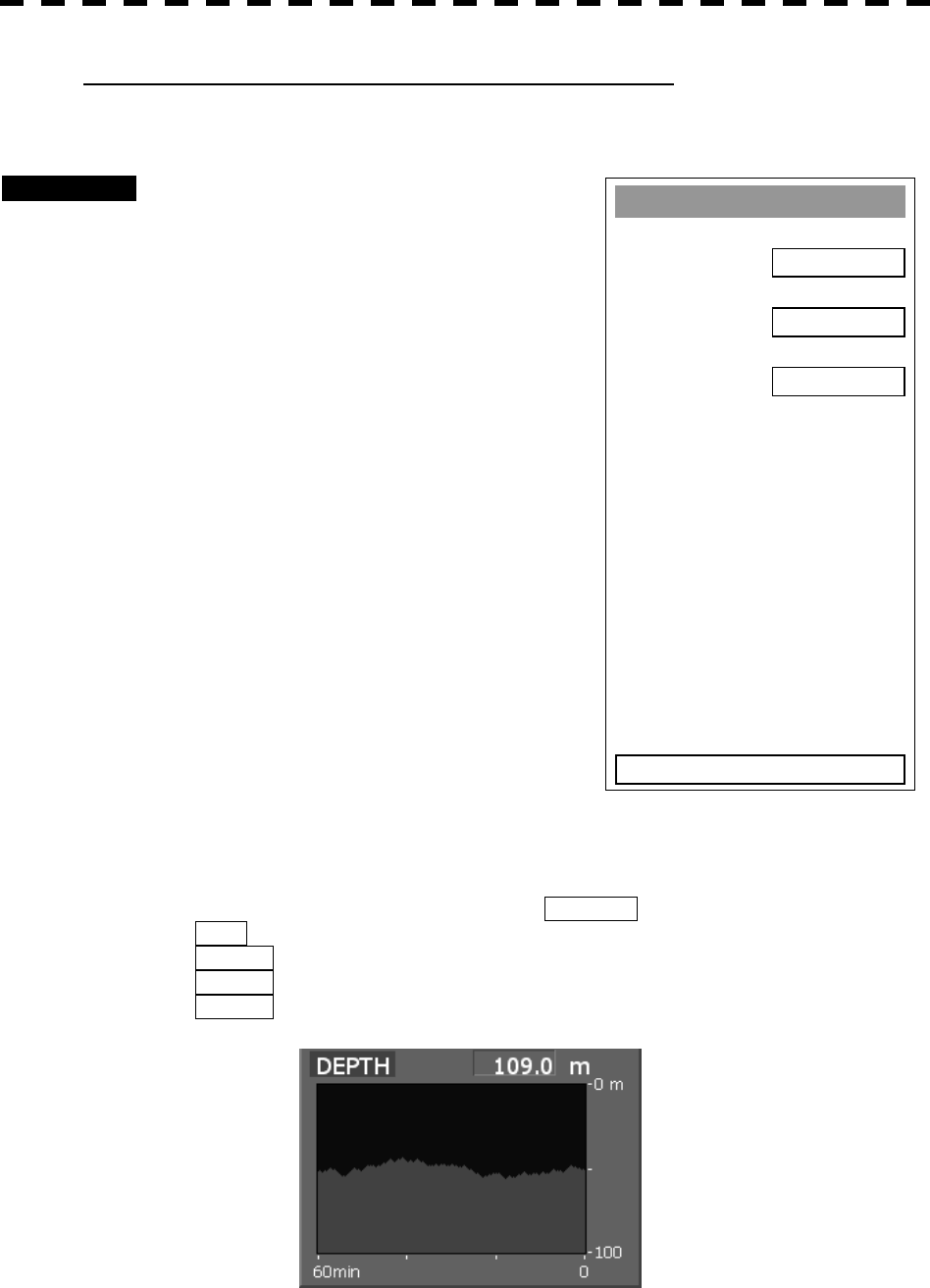
3─105
Displaying Water Depth Graph (Depth Graph Setting)
· Displays a water depth graph using received water depth information.
Procedures 1 Press [RADAR MENU] key twice.
Press [4] key.
Press [4] key.
The Depth Graph Setting Menu will appear.
Detail information about screen display can be
set by changing the settings of the menu items.
[1] Depth Graph Display
· Determine whether to display received water depth
information with a graph.
· The graph is displayed in one of three ATA/ARPA’s numeric data display areas.
· When the water depth graph is displayed, the sizes of the ATA/ARPA’s numeric data display areas are
exclusively decreased.
· Depth Graph Display is set to ON/OFF each time the OPTION button on the screen is pressed.
OFF : Does not display a water depth graph.
AREA1 : Displays the water depth graph in numeric data display area 1.
AREA2 : Displays the water depth graph in numeric data display area 2.
AREA3 : Displays the water depth graph in numeric data display area 3.
Depth Graph Settin
g
1. Depth Graph Display
OFF
2. Depth Ran
g
e
50 m
3. Time Ran
g
e
10 min
0. EXIT
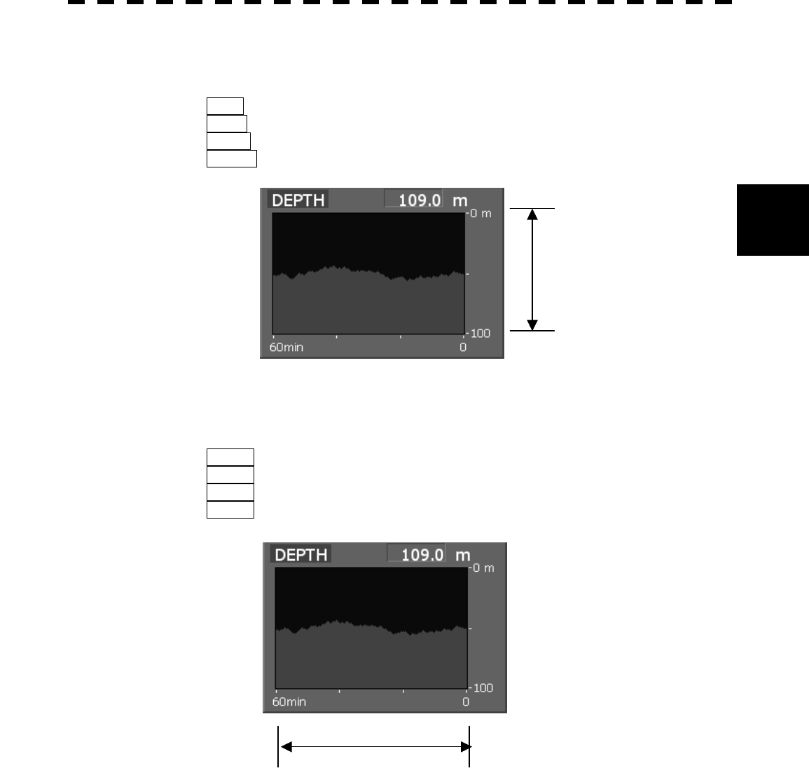
3─106
3
3.10
A
PPLIED OPERATIONS
[2] Depth Range
· Select the depth range on the water depth graph.
50m : Sets 50 m as the depth range.
100m : Sets 100 m as the depth range.
250m : Sets 250 m as the depth range.
AUTO : Uses the depth range in the DPT sentence included in received data.
[3] Time Table
· Select the time range on the water depth graph.
10min : Sets 10 minutes as the time range.
15min : Sets 15 minutes as the time range.
30min : Sets 30 minutes as the time range.
60min : Sets 60 minutes as the time range.
Depth range
Time range
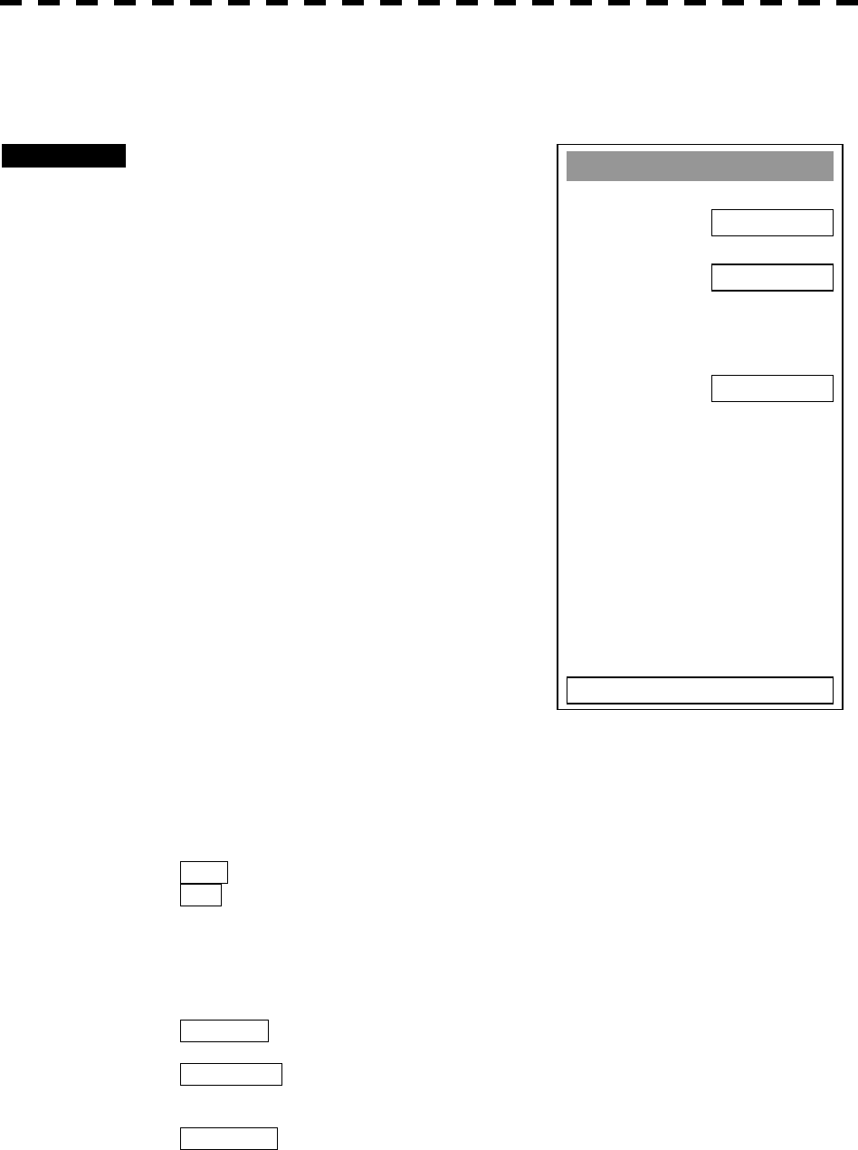
3─107
3.10.5 Set Scanner (TRX Setting)
This function enables the setting of detail information about a scanner
Procedures 1 Press [RADAR MENU] key twice.
Press [5] key.
The TRX Setting Menu will appear.
Detail information about antenna operation
can be set by changing the settings of the
menu items.
[1] PRF Fine Tuning
· Fine-tune the transmitting repetition frequency of the
transmitter in the range 90 to 100%.
· If radar’s interference patterns are concentrically displayed,
increment or decrement the set value by 3 to 4 in order to
heighten the effect of interference rejection.
· The same operation can be performed by pressing the
[TX/STBY] key several times.
· One of 32 levels 0-31 can be set.
[2] Jamming
· Use the jamming function to control the transmitting repetition frequency of the transmitter.
· This function is effective when interference patterns caused by radar equipment of the same model do
not disappear.
OFF : Disables the jamming function.
ON : Enables the jamming function.
[3] XMIT Repitation FREQ
· Select the operation mode the transmitting repetition frequency of the transmitter.
NORMAL Standard mode: Both appropriate sensitivity and magnetron’s life
expectancy are maintained.
ECONOMY Power saving mode: Sensitivity slightly lowers, but the service life of
magnetron is prolonged when short pulses are
used.
HI POWER High sensitivity mode: Sensitivity improves when long pulses are used,
but the service life of magnetron is slightly
shortened.
TRX Settin
g
1. PRF Fine Tunin
g
0
2. Jammin
g
OFF
4. XMIT Repitation FREQ
6. Band Select
0. EXIT
NORMAL

3─108
3
3.10
A
PPLIED OPERATIONS
[6] Band Select
· Select band of antenna. This item is effective only when the antenna in connection supports two
frequencies.
X-Band : Selects the X-band side from the two frequencies.
S-Band : Selects the S-band side from the two frequencies.
X/S-band : Supports the two frequencies.
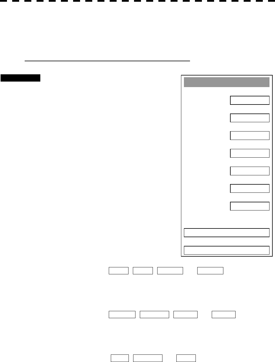
3─109
3.10.6 Set Chart Display (Map Setting)
This function enables the setting of detail information about chart display.
Setting JRC/ERC Chart Display (JRC/ERC Setting)
Procedures 1 Press [RADAR MENU] key twice.
Press [9] key.
Press [5] key.
Press [3] key.
The JRC/ERC Setting Menu will appear.
Detail information about the colors and
brilliance of JRC/ERC chart display can be set
by changing the settings of the menu items.
The data of colors and brilliance can be stored
for each day/night mode.
[1] Day/Night
· Select a desired display mode before setting the colors and
brilliance of chart display.
· There are four selection items: DAY1 , DAY2 , NIGHT1 , and NIGHT2 .
[2] Color of Land
· Select the color of land display.
· There are four selection items: BROWN , YELLOW , GREEN , and WHITE .
[3] Bright of Land
· Select the brilliance of land display.
· There are three selection items: LOW , MEDIUM , and HIGH .
JRC/ERC Settin
g
1. Day/Ni
g
ht
DAY1
2. Color of Land
YELLOW
3. Bri
g
ht of Land
HIGH
4. Color of Sea
BLUE
5. Bri
g
ht of Sea
HIGH
6. Color of Name
WHITE
7. Bri
g
ht of Name
HIGH
9. Next Pa
g
e
0. EXIT
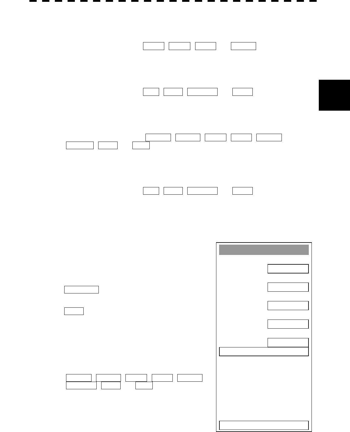
3─110
3
3.10
A
PPLIED OPERATIONS
[4] Color of Sea
· Select the color of sea display.
· There are four selection items: GRAY , CYAN , BLUE , and GREEN .
[5] Bright of Sea
· Select the brilliance of sea display.
· There are four selection items: OFF , LOW , MEDIUM , and HIGH .
[6] Color of Name
· Select the color of a location name.
· There are eight selection items: BLACK , WHITE , CYAN , BLUE , GREEN ,
YELLOW , PINK , and RED .
[7] Bright of Name
· Select the brilliance of location name display.
· There are four selection items: OFF , LOW , MEDIUM , and HIGH .
[9] Next Page
· Moves to the next page.
· The next page of the JRC/ERC Setting Menu will appear.
[1] LAT/LON Line
· Select the mode to display latitude and longitude lines.
· There are two selection items:
LINE NUM : Displays both latitude/longitude lines
and values indicating the latitude and
longitude.
NUM : Displays only the values indicating the
latitude and longitude.
[2] Color of L/L Line
· Select the colors that are to represent latitude and longitude
lines.
· There are eight selection items:
BLACK , WHITE , CYAN , BLUE , GREEN ,
YELLOW , PINK , and RED .
JRC/ERC Settin
g
1. LAT/LON Line
LINE NUM
2. Color of L/L Line
BLUE
3. Bri
g
ht of L/L Line
HIGH
4. ERC Display Request
ON
5. ERC Mark
SMALL
6. JRC Card Display Settin
g
0. EXIT
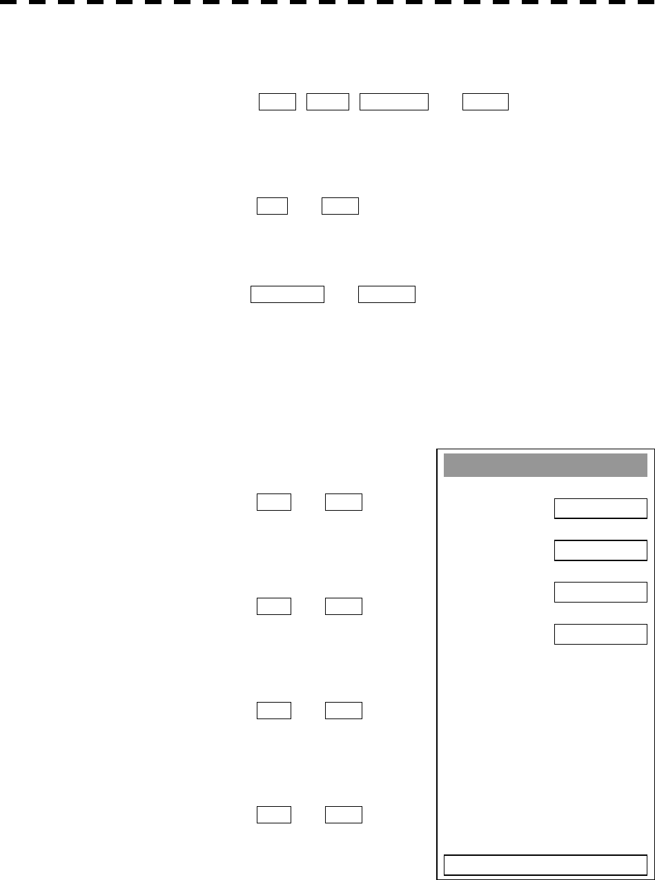
3─111
[3] Bright of L/L Line
· Select the brilliance of latitude/longitude line display.
· There are four selection items: OFF , LOW , MEDIUM , and HIGH .
[4] ERC Display Request
· Display of the information within ERC can be switched between ON and OFF .
· There are two selection items: ON , and OFF .
[5] ERC Mark
· Select the size of mark display on the ERC chart.
· There are two slection items: NORMAL and SMALL .
[6] JRC Card Display
· Sets the display contents of the JRC card.
· The JRC Card Display Setting Menu will appear.
[1] Light House
· Determine whether to display lighthouses.
· There are two selection items: ON and OFF .
[2] Buoy
· Determine whether to display buoys.
· There are two selection items: ON and OFF .
[3] Rough Line
· Determine whether to display rough lines.
· There are two selection items: ON and OFF .
[4] Other Line
· Determine whether to display other lines.
· There are two selection items: ON and OFF .
JRC Card Display Settin
g
1. Li
g
ht House
ON
2. Buoy
ON
3. Rou
g
h Line
ON
4. Other Line
ON
0. EXIT
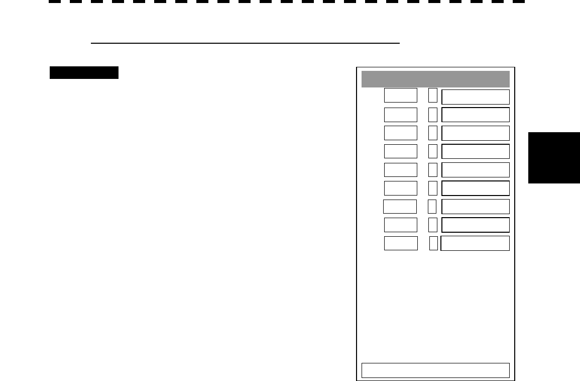
3─112
3
3.10
A
PPLIED OPERATIONS
Setting Contour Lines on JRC Chart (Contour Setting)
Procedures 1 Press [RADAR MENU] key twice.
Press [9] key.
Press [5] key.
Press [4] key.
The Contour Setting Menu will appear.
Depths and display colors can be set for 9
contour lines in total: 8 for depth specification
and 1 for other depths.
2 Select the number of depth to be
changed, pressing the numeric key.
The depth input screen will appear. Enter
the value as the depth to be set.
Subsequently, the display line list will appear.
3 Select the number of display line to
be set, pressing the numeric key.
Subsequently, the display color list will
appear.
4 Select the number of display color to be set, pressing the numeric key.
The selected color to represent the contour lines of the depth will be set.
To change the settings of other depths, repeat steps 2 and 3.
Contour Settin
g
1. 10m -- GREEN
2. 20m -- BLUE
3. 30m -- BLUE
4. 40m -- BLUE
5. 50m -- BLUE
6. 60m -- BLUE
7. 70m -- BLUE
8. 80m -- BLUE
9. Other -- BLUE
0. EXIT
1-99:
100-999:
1000-9999:
3─113
Set C-MAP Display
Procedures 1 Press [RADAR MENU] key twice.
Press [9] key.
The Plot Menu will appear.
2 Press [5] key.
The MAP Setting Menu will appear.
3 Press [2] key.
The C-MAP Setting Menu will appear.
[1] Grid Display
· Sets whether or not latitudinal longitudinal lines are displayed with C-MAP.
· Each time you press [1] key, the grid display item is switched between ON and OFF.
· ON: Displayed
OFF: Not displayed
[2] Sounding Display
· Sets whether or not soundings values are displayed with C-MAP.
· Each time you press [2] key, the souding display item is switched between ON and OFF.
· ON: Displayed
OFF: Not displayed
C
-Map Settin
g
1. Grid Display
ON
2. Soundin
g
Display
ON
3. Soundin
g
Unit
FEET
4. Li
g
ht Sectors Display
ON
5. Li
g
ht Sectors Level
H
0. EXIT

3─114
3
3.10
A
PPLIED OPERATIONS
[3] Sounding Unit
· Sets the units when soundings values are displayed with C-MAP.
· Press [3] key to display a list of units.
· 1: FEET
2: FATHOM
3: METERS
4: DECIMAL FATHOM
You can select one from the above four items. Select the item you want to set, pressing the numeric keys
[1] to [4].
[4] Light Sectors Display
· Sets whether or not the light sectors are displayed.
· Each time you press [4] key, the light sectors display item is switched between ON and OFF.
· ON: Displayed
OFF: Not displayed
[5] Light Sectors Level
· Sets levels when light sectors are displayed with C-MAP.
· Press [5] key to display a list of levels.
· Selects one from level settings A to H.
3─115
Correcting Chart Position (Map Display Setting)
Procedures 1 Press [RADAR MENU] key twice.
Press [9] key.
Press [5] key.
Press [5] key.
The Map Display Setting Menu will appear.
There are three methods for correcting the chart
position.
[1] Shift Coast Line 1
Set the correction value by operating the cursor.
1 Press [1] key while the Map Display
Setting Menu is open.
2 Move the cursor to the chart on which
a position is to be corrected, and
press [ENT] key.
3 Move the cursor to the radar video of
which position is to be corrected, and
press [ENT] key.
SETTING (correcting) will be indicated for Shift Coast Line 1.
At this time, MAP SHIFT will appear at the radar display button 29 on page 2-7,
indicating that the position is being corrected.
Cancellation of Shift Coast Line 1
1 Press [1] key while the MAP Display Setting Menu is open.
DELETE (no correction) will be indicated for Shift Coast Line 1.
At this time, MAP SHIFT will disappear from the lower right of the radar display.
Map Display Settin
g
1. Shift Coast Line 1
SETTING
2. Shift Coast Line 2
N0.000
’
E0.000
’
3. LAT/LON Correction
N0.000
’
E0.000
’
N 35°00.000’
E140°00.000’
5. LORAN C Correction
0. EXIT
4. MAP Center Position
6. LORAN A Correction

3─116
3
3.10
A
PPLIED OPERATIONS
[2] Shift Coast Line 2
Set a correction value pressing the numeric values.
A correction value can be entered in the range -9.999’ to +9.999’.
1 Press [2] key while the Map Display Setting Menu is open.
The chart position correction value input screen will appear.
2 Enter the correction value for the latitudinal direction, pressing the
numeric keys.
To switch between the north and south, turn the [MULTI] control.
3 Press [ENT] key.
The correction value for the latitudinal direction will be determined.
4 Enter the correction value for the longitudinal direction, pressing the
numeric keys.
To switch between the east and west, turn the [MULTI] control.
5 Press [ENT] key.
The correction value for the longitudinal direction will be determined.
At this time, MAP SHIFT will appear at the radar display button 29 on page 2-7,
indicating that the position is being corrected.
Cancellation of Shift Coast Line 2
1 Press [2] key while the MAP Display Setting Menu is open.
The chart position correction value input screen will appear.
2 Press [0] key, and then [ENT] key.
The correction value for the latitudinal direction will be set to 0.
3 Press [0] key, and then [ENT] key.
The correction value for the longitudinal direction will be set to 0.
At this time, MAP SHIFT will disappear from the lower right of the radar display.

3─117
[3] LAT/LON Correction
This method corrects a chart position by changing the values of latitude and longitude that are sent by the
navigation equipment.
Only our service engineers are to use this correction method because the contents of data such as trails
data to be saved are changed when the method is used.
A correction value can be entered in the range -9.999’ to +9.999’.
1 Press [3] while the MAP Display Setting Menu is open.
The latitude/longitude correction value input screen will appear.
2 Enter the correction value for the latitudinal direction, pressing the
numeric keys.
To switch between the north and south, turn the [MULTI] control.
3 Press [ENT] key.
The correction value for the latitudinal direction will be determined.
4 Enter the correction value for the longitudinal direction, pressing the
numeric keys.
To switch between the east and west, turn the [MULTI] control.
5 Press [ENT] key.
The correction value for the longitudinal direction will be determined.
Cancellation of LAT/LON Correction
1 Press [3] key while the MAP Display Setting Menu is open.
The latitude/longitude correction value input screen will appear.
2 Press [0] key, and then [ENT] key.
The correction value for the latitudinal direction will be set to 0.
3 Press [0] key, and then [ENT] key.
The correction value for the longitudinal direction will be set to 0.

3─118
3
3.10
A
PPLIED OPERATIONS
[4] MAP Center Position
This method corrects a chart position by entering the values of latitude and longitude at own ship’s
position in manual mode.
If latitude and longitude data sent by the navigation equipment has been entered, the data has priority
over the manually entered values.
1 Press [4] key while the MAP Display Setting Menu is open.
The latitude/longitude correction value input screen will appear.
2 Enter the value as latitudinal, pressing the numeric keys.
To switch between the north latitude and south latitude, turn the [MULTI] control.
3 Press [ENT] key.
The entered value will be determined as latitude.
4 Enter the value as longitude, pressing the numeric keys.
To switch between the east longitude and west longitude, turn the [MULTI] control.
5 Press [ENT] key.
The entered value will be determined as longitude.
3─119
3.10.7 Set LORAN C (LORAN C Correction)
This function enables LORAN C time difference display for the own ship’s position and cursor position.
Setting LORAN C
Procedures 1 Press [RADAR MENU] key twice.
Press [9] key.
Press [5] key.
Press [5] key.
Press [5] key.
The LORAN C Correction Menu will appear.
The chain and time difference for LORAN C
time difference display can be set by changing
the settings of the menu items.
[1] Chain
· Set the chain.
· Enter the value in the range 0000 to 9999 by using the numeric keys.
· Only a value in the table can be entered.
[2] TD1, [3] TD2
· Enter the TD value for slave station 1/2.
[4] TD1 Correction, [5] TD2 Correction
· Enter the sound velocity time correction value for the TD value of slave station 1/2.
LORAN C Correction
1. Chain
9970
2. TD1
13
3. TD2
58
4. TD1 Correction
0.1 uS
5. TD2 Correction
0.2 uS
0. EXIT

3─120
3
3.11 USE FUNCTION SWITCH [FUNC]
“Radar Function Setting” is provided for always obtaining the best radar video by storing complex radar signal
processing settings in the optimum status by use, and calling the setting in accordance with the conditions for
using the function.
Functions are factory-set for general use, and the settings can be fine adjusted by operating the menu.
Four function modes are available, and they are factory-set as follows:
Function 1: COAST Useful for observing short-range videos
Function 2: DEEP SEA Suitable for general ocean navigation
Function 3: FISH NET Useful for small target.
Function 4: STORM Useful for observing videos in stormy weather
3.11.1 Operation Procedures
Calling a Function
Procedures 1 Press the [FUNC] key.
Each time the [FUNC] key is pressed, the selection changes cyclically as follows:
Function Off ® Function 1 ® Function 2 ® Function 3 ® Function 4 ® Function Off
The currently called function mode will be indicated at the lower left of the radar display.
* Switching can be done each time button 13 on the radar display on page 2-7 is pressed.
Changing Function Setting (temporary change)
· When radar signal processing setting is changed by using the menu or button on the radar
display while function 1 to 4 is called, the change is temporarily reflected to the operating state.
· Since this method does not change the memory contents, the new setting is deleted as soon as
another function is called.
· When the previous function is called again, operation is performed according to the memory
contents.
Changing Function Setting (memory contents change)
· To change the memory contents of functions 1 to 4, use the function setting menu.
· To display the function setting menu, press [RADAR MENU] twice, [1] key, and then [8] key.
· Press the numeric key corresponding to the target function number.
· The function setting menu consists of five pages. To switch between the pages, select [0] key
Previous Page or [9] key Next Page.

3─121
3.11.2 Function Setting Menu Items
The function setting menu has the items below.
Page 1
Page 2
Page 3
Page 4
Page 5
1. Mode Name of the mode to be used
2. IR Radar interference rejection OFF/LOW/MEDIUM/HIGH
3. Process Video process OFF/・・・・
4. Target Enhance Target expansion OFF/ LEVEL1/LEVEL2/LEVEL3
5. Auto STC/FTC Automatic clutter suppression OFF/AUTO SEA/AUTO RAIN
7. Save Present State Saving of the present state
1. PL 0.75nm Standard pulse length of 0.75 nm range SP/MP
2. PL 1.5nm Standard pulse length of 1.5 nm range SP/MP/LP
3. PL 3/4nm Standard pulse length of 3 nm range SP/MP/LP
4. PL 6/8nm Standard pulse length of 6 nm range SP/MP/LP
5. PL 12nm Standard pulse length of 12 nm range SP/MP/LP
6. PL 16nm Standard pulse length of 16 nm range SP/MP/LP
1. Video Latitude Dynamic range of radar video NORMAL/WIDE/NARROW
/SUPER WIDE
2. Video Noise Rejection Radar video noise rejection OFF/LEVEL1/LEVEL2
3. Auto DR Control Automatic dynamic range control OFF/ON
4. Process Switch Radar video process switching OFF/RANGE FIX/AUTO
5. 2nd Process Mode Second video process mode OFF/・・・・
6. Process Switch Range Video process switching range Range setting
7. Fast Target Detection Fast moving target detection OFF/ON
1. Trails Interval Radar trails length OFF/・・・・
2. Trails Mode Radar trails mode TRUE/RELATIVE
3. Trails REF Level Radar trails plotting threshold LEVEL1-4
4. Trails Reduction Thinning of radar trails OFF/LEVEL1-3
5. Time/Cont Combine Superimpose-display of time radar
trails and continuous radar trails OFF/ON
6. Trails Process Radar trails video process OFF/ON
7. Max Interval Maximum time for radar trails display SHORT/MEDIUM/LONG/SUPER LONG
1. Gain Offset Sensitivity correction Correction value setting
2. XMIT Repitation FREQ Transmitting repetition frequency NORMAL/ECONOMY/HIPOWER
3. Small Buoy Detection Small target detection mode OFF/ON
4. Fishnet Detection Fishnet detection mode OFF/ON
5. Antenna Height Antenna height DEFAULT/-5m/5-10m/10-20m/20m

3─122
3
3.11 USE FUNCTION SWITCH
3.11.3 Overview of Function Operations
The following outlines the operation of each function selected from the function setting menu:
[Page 1] [1] MODE (Mode)
· Selects the function name to be indicated at the lower left of the radar display when the function is
selected.
· When the setting is changed back to the factory setting, the initial value of the selected mode is
called.
· The following 11 modes are provided:
COAST: Use this mode to monitor a relatively short range, for example, bays and coasts
where many boats and ships are running. (Importance is attached to resolution.)
DEEPSEA: Use this mode to monitor a relatively long range, for example, the open sea.
(Importance is attached to long-range sensitivity.)
FISHNET: Use this mode to detect small targets such as fishnets of round haul netters hidden
by sea clutter returns. (Importance is attached to sea clutter suppression, and
sensitivity to moving targets lowers.)
STORM: Use this mode when many rain/snow clutter returns or sea clutter returns are
detected in stormy weather. (Importance is attached to rain/snow clutter and sea
clutter suppression, and sensitivity slightly lowers.)
CALM: Use this mode when only a few rain/snow clutter returns or sea clutter returns are
detected.
RAIN: Use this mode when sea clutter is not strong but rain/snow clutter is strong.
(Importance is attached to rain/snow clutter suppression, and sensitivity slightly
lowers.)
BIRD: Use this mode to detect tens of seabirds at low altitude during coastal navigation
or hundreds of seabirds at high altitude during ocean navigation.
LONG: Use this mode to detect small targets at relatively long distance in the open sea.
BUOY: Use this mode to detect small targets like radio buoys in areas outside the sea
clutter area. (This mode displays targets of which detection probability is low.)
USER1: General mode used when the nine modes above are not applicable
USER2: General mode used when the nine modes above are not applicable
[Page 1] [2] IR (radar interference rejection)
· Same function as IR in the Main Menu
[Page 1] [3] Process (video process)
· Same function as PROCESS in the Main Menu
[Page 1] [4] Target Enhance
· Same function as TARGET ENHANCE in the Main Menu

3─123
[Page 1] [5] Auto SEA/RAIN (Auto STC/FTC)
· Detects unwanted waves such as rain/snow clutter and sea clutter and automatically suppresses them.
· When the sea state or weather changes, this function automatically performs suppression processing
in accordance with the situation.
· Suppression processing is not full automatic, and requires the operator to control the afterimages of
unwanted waves.
· To control the afterimage of sea clutter, use the [SEA] control.
· To control the afterimage of rain/snow clutter, use the [RAIN] control.
· In areas where the density of unwanted waves is low, unwanted waves may remain being judged as
targets. Thus, use the automatic clutter suppression mode together with the video process mode.
· Characteristics of the automatic clutter suppression function:
OFF: Disables the automatic clutter suppression function.
Select OFF when rain/snow clutter and sea clutter are not strong or when the ship
is in a bay.
AUTO SEA: Automatically detects the strength of sea clutter, and performs the most suitable
sea clutter suppression processing.
Even when the strength of sea clutter varies depending on the wind direction,
AUTO SEA performs the most suitable suppression processing.
Land like islands can be displayed naturally.
Since rain clouds outside sea clutter areas are recognized as land, there is no effect
of suppressing rain/snow clutter.
AUTO RAIN: Along with AUTO SEA, AUTO RAIN automatically detects the strength of
rain/snow clutter, and performs the most suitable rain/snow clutter suppression
processing.
When rain clouds are scattered about, AUTO RAIN performs rain/snow clutter
suppression processing for only the rain-cloud areas.
Since land is recognized as rain clouds, land videos become obscure.
[Page 2] [1]-[7] PL (Pulse Width)
· Sets the standard transmitter pulse length in each range.
· When the range is called, the pulse range is used.
[Page 3] [1]-[7] Radar signal processing settings (Process Setting)
· Same functions as those in the Process Setting Menu generally used
[Page 4] [1]-[7] Radar trails settings (Trails Setting)
· Same functions as in the Trails Setting of the RADAR Menu generally used

3─124
3
3.11 USE FUNCTION SWITCH
[Page 5] [1] Gain Offset
· Corrects sensitivity while the function mode is called.
· Since the displayed noise level varies depending on the combination of the video process mode and
the interference rejection level, sensitivity needs fine adjustment for always obtaining the highest
level.
· The sensitivity correction function saves the correction value set by the sensitivity control in each
function mode, so it can obtain the highest sensitivity without the sensitivity control being operated
when the function mode is changed.
· To set high sensitivity, set a value on the “+” side.
· To set low sensitivity, set a value on the “-” side.
· When the radar interference rejection level is increased, the noise level is lowered. Thus, set a
sensitivity correction value to the “+” side.
· When the video process mode 3SCAN CORR, 4SCAN CORR, or 5SCAN CORR is used, the noise
level is lowered. Thus, set a sensitivity correction value to the “+” side.
· When the video process mode REMAIN or PEAK HOLD is used, noise is hard to disappear. Thus,
set a sensitivity correction value to the “-” side.
[Page 5] [2] XMIT Repitation FREQ.
· Same function as in the TRX Setting of the RADAR Menu generally used
[Page 5] [3] Small Buoy Detection
· Reduces the loss of signal processing during detection of small targets.
OFF: Activates the general signal processing mode.
ON: Activates the small buoy detection mode that reduces the loss of signal processing.
[Page 5] [4] FishNet Detection
· Use this mode to detect small targets hidden by sea clutter returns.
· This function becomes more effective when the AUTO RAIN clutter suppression function is used
together.
OFF: Activates the general signal processing mode.
ON: Activates the fishnet detection mode.
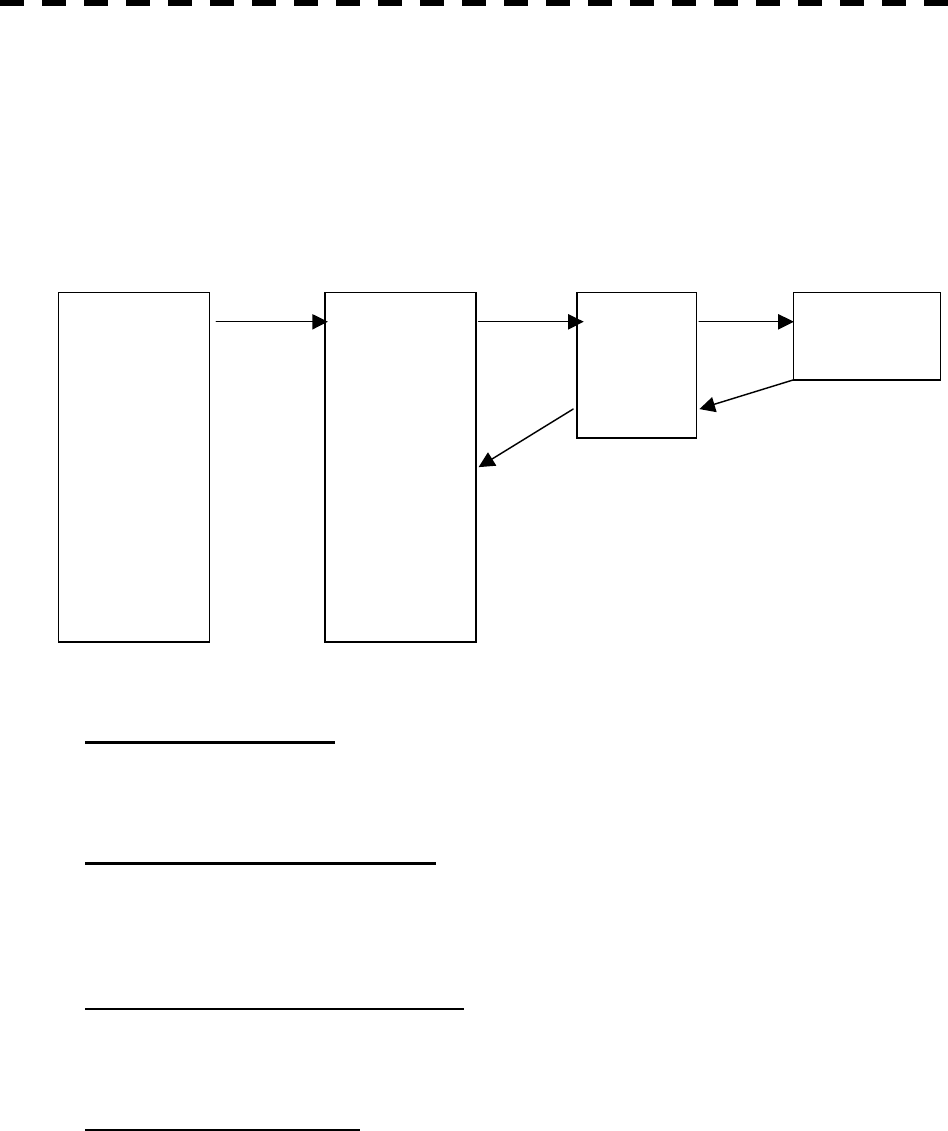
3─125
3.11.4 Overview of Stored Function Setting Data
The overview of stored function setting data is as follows:
· Factory-set data: Stored data that general operation cannot change
· Default data: Standard data of each function mode that users can change
· Data that can be called: Stored data that can be called by pressing the [FUNC] key
[Page 1] [1] Call Mode
· Calls the standard setting of the mode, and stores it for the function number.
[Page 1] [6] Save Present State
· The currently operating state can be stored for the function number.
· Use this function to store the state of good setting that will be frequently used.
[Page 5] [7] Save Default of Mode
· Stores the setting of the current function number, as the default setting of the mode.
[Page 5] [8] Initialization
· Changes the memory contents of the mode, which is used with the current function number, back to
the factory setting.
COAST
DEEPSEA
FISHNET
STORM
CALM
RAIN
BIRD
LONG
BUOY
USER1
USER2
COAST
DEEPSEA
FISHNET
STORM
CALM
RAIN
BIRD
LONG
BUOY
USER1
USER2
FUNC1
FUNC2
FUNC3
FUNC4
PRESENT
[5]-[8] [1]-[1]
[5]-[7]
[FUNC]
[1]-[7]
Function Setting
Factory-set data
Function Setting
Default data
Function Setting
Data that can be called Current data
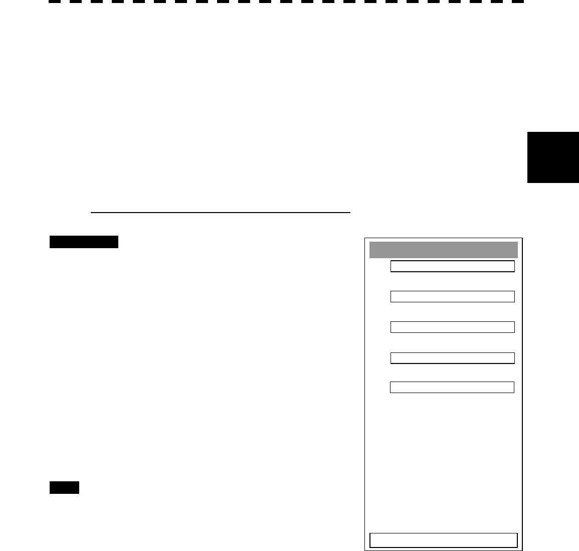
3─126
3
3.11 USE FUNCTION SWITCH
Load PIN Data
1.
2.
3.
4.
5.
0. EXIT
3.11.5 Personal Information (PIN Setting)
The operation status of the radar is recorded. If the system is operated by more than one operator, the
operators can register operation status as suitable for them and call the status. Operation status for up to
five operations can be registered, and a name can be assigned to each status. (Up to 10 alphanumeric
characters)
* Data stored as personal information
· Day/Night mode setting
· Brilliance
· Alarm volume
· Vector length/mode
· Various types of image processing (IR, ENH, PROC, FUNC)
[1] Calling Operation Status (Load PIN Data)
Procedures 1 Press [RADAR MENU] key twice.
Press [8] key.
The Radar Sub Menu will appear.
2 Press [1] key.
The PIN Setting Menu will appear.
3 Press [1] key.
The Load PIN Data Menu will appear.
4 Select the item you want to load,
pressing the numeric keys [1] to [5].
The Load Execution Check Menu will appear.
Select “Yes” for loading.
Exit 1 Press [RADAR MENU] key.
The Target Information Display Menu will
reappear.
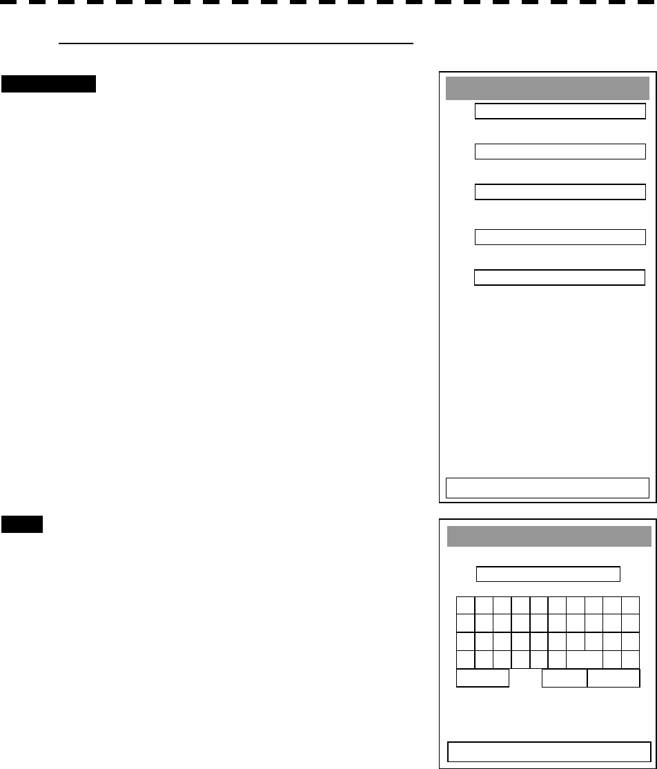
3─127
Save PIN Data
1.
2.
3.
4.
5.
0. EXIT
[II] Saving Operation Status (Save PIN Data)
Procedures 1 Press [RADAR MENU] key twice.
Press [8] key.
The Radar Sub Menu will appear.
2 Press [1] key.
The PIN Setting Menu will appear.
3 Press [2] key.
The Save PIN Data Menu will appear.
4 Select the number corresponding to
the place where you want to save
status, pressing the numeric keys [1]
to [5].
The Code Input Menu will appear.
5 Using numeric key, enter the name and
then press [ENT] key.
Data will be saved with the entered name.
Exit 1 Press [RADAR MENU] key.
The Target Information Display Menu will
reappear.
1 2 34 5 6 7 8 90
B C DE F G H I JA
L M N O P Q R S TK
V W X Y Z SP < >U
DEL ENT BS
Save PIN Data
EXIT
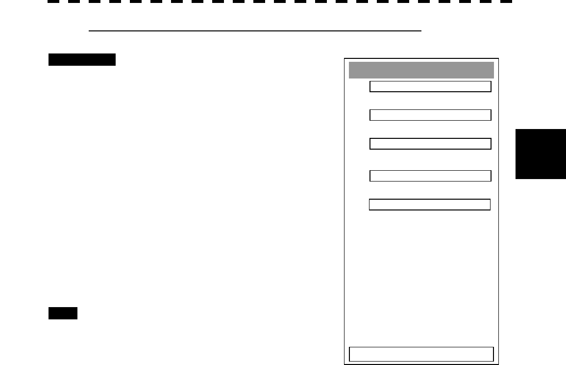
3─128
3
3.11 USE FUNCTION SWITCH
[III] Erasing Registered Operation Status (Delete PIN Data)
Procedures 1 Press [RADAR MENU] key twice.
Press [8] key.
The Radar Sub Menu will appear.
2 Press [1] key.
The PIN Setting Menu will appear.
3 Press [3] key.
The Delete PIN Data Menu will appear.
4 Select the file you want to erase,
pressing the numeric keys [1] to [5].
The Delete Execution Check Menu will
appear.
Select “Yes” for deletion.
Exit 1 Press [RADAR MENU] key.
The Target Information Display Menu will
reappear.
Delete PIN Data
1.
2.
3.
4.
5.
0. EXIT
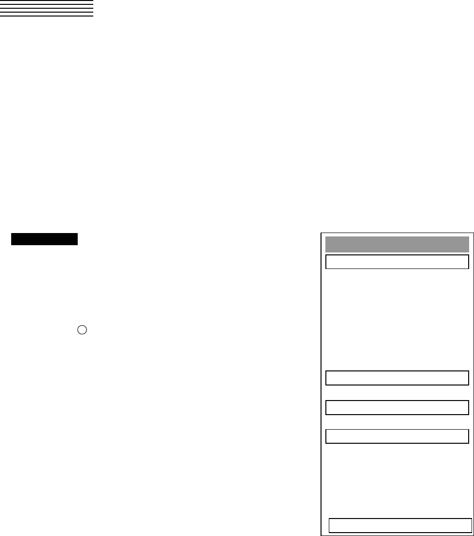
3─129
Plot Menu
1. Own Track Settin
g
5. Map Settin
g
6. MEM CAPA/Copy
7. CLR MEM INIT Card
0. EXIT
3.12 USING CARD
This radar has two card slots. Inserting a flash memory card (option) into a card slot, you can save the
following contents, saved in the processor, in the card or can read data from the card to the processor.
· Trails of own ship: 7000 points maximum
· Track of other ship: 20 target×1500 points
· Mark Line (including mark lines created by user map): 20000 points maximum (plotter option)
· Waypoint: 99 points maximum (plotter option)
· Route: 10 routes maximum (plotter option)
These pieces of information can be saved in a flash memory card as a file. The internal capacity is as
large as only a file. An internally created file can be saved until the flash memory card is full.
3.12.1 Save in and Transfer to Card (MEM CAPA/Copy)
Procedures 1 Press [RADAR MENU] key twice.
The Radar Menu will appear.
2 Press [9] key.
The Plot Menu will appear.
* Button 56 on the radar display on page 2-7 is also available to save
and transfer data.
3 Press [6] key.
The MEM CAPA/Copy window will appear.
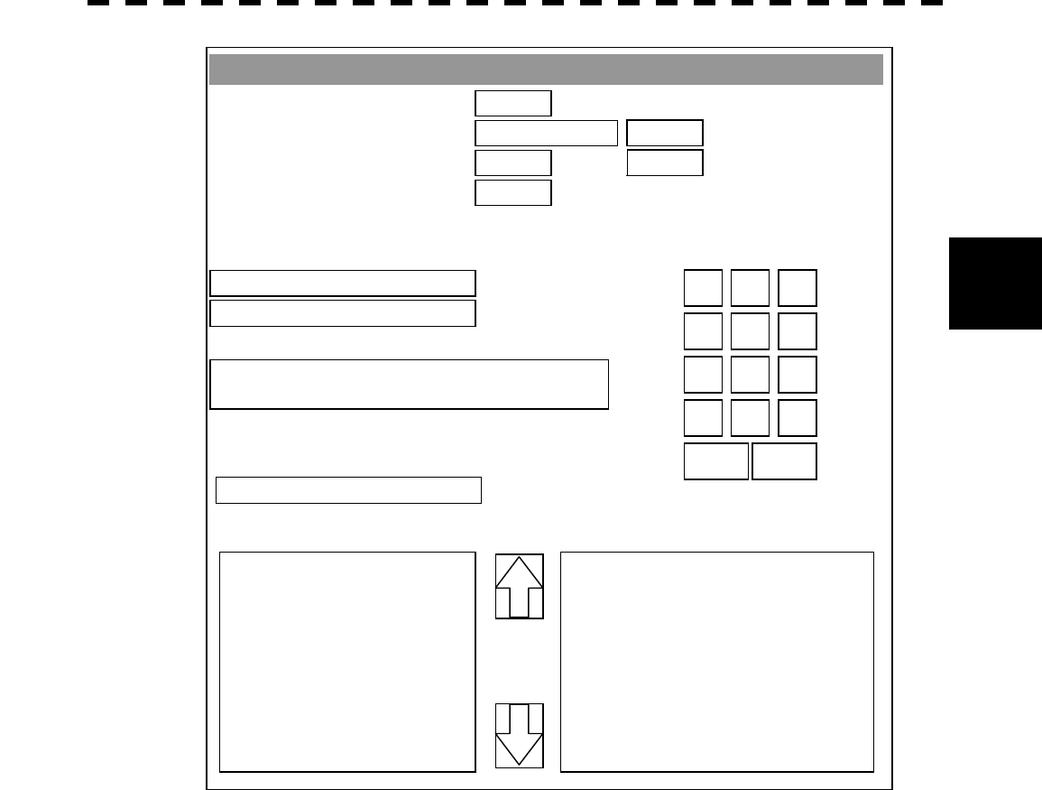
3─130
3
3.12 Using CARD
· Information saved in the processor is displayed in the Memory Content.
Total: Total number of data points
Track: Number of data points for own ship's track (7000 points maximum)
Remain: Number of remaining data points of own ship's track that can be saved
Mark/Line: Number of mark and line points made with user map (20000 points maximum only
when a plotter option is installed)
Remain: Number of remaining data points of marks and lines that can be saved
WPT: Number of data points of created waypoints (99 points maximum)
Remain: Remaining waypoints that can be saved
Route: Number of data points of created routes (10 routes maximum)
Remain: Remaining routes that can be saved
· File names and information saved in the card is displayed in Card 2.
· Arrows next to Card 2 are used to scroll the contents of Card 2.
· Numeric key is used to give a file name.
MEM CAPA/Copy
1. Copy Internal -> Card 2
2. Copy Card 2 -> Internal
3. Copy Card 1 -> Card 2
4. Clear File
0. EXIT
7. Show Card 1
8. Show Card 2
0000
OVER WRITE
0000
0000
0000
0000
->
4 5 6
1 2 3
7 8 9
- 0
+
CL
R
ENT
Memory Content
T
OTAL
T
RAC
K
Remain
MARK/LINE
Remain
WPT
Remain
ROUTE
Remain
CARD Remain
Card 2

3─131
[I] Copy Internal Information to Card 2 (Copy Internal ® Card 2)
Procedures 1 Press [1] key while the CAPA/Copy Menu is open.
A file name to copy Internal information to Card 2 can be entered.
2 Using the numeric key, enter a file name.
After enter a file name, select ENT.CLR will be cancelled.
The system writes internal information into Card 2 with an entered number used as a file
name.
The capacity of information that can be saved in the internal portion is limited to the
maximum number of points in items described on the previous page. For the capacity of
information that can be saved in a card, the system can save information in a card until the
card capacity is filled with a file, counting the information saved in the internal portion as
a file.
[II] Read Information from Card 2 to Internal Portion(Copy Card 2 ®
Internal)
Procedures 1 Press [2] key while the CAPA/Copy Menu is open.
A file name to copy information from Internal portion to Card 2 can be entered.
Read the file name displayed in the Card 2 window.
2 Using the numeric key, enter a file name.
After having enter the name, select ENT.CLR will be cancelled.
The entered file name is read from Card 2 to the internal portion.
When information is to be transferred from Card 2 to the internal portion in the ADD mode, the
information can be copied from multiple files. However, information cannot be read when the number
of points for an item has reached the maximum. In the ADD mode, the WPT and Route are overwritten.
[III] Copy Information from Card 1 to Card 2 (Copy Card 1 ® Card 2)
Procedures 1 Press [3] key while the CAPA/Copy Menu is open.
A file name to copy information from Card 1 to Card 2 can be entered.
2 Using the numeric key, enter a file name.
Using the numeric key, euter a file name to be copied.
After having enter the name, select ENT. CLR will be cancelled.
3 Using the numeric key, enter a file name to copy.
After having enter the name, select ENT.CLR will be cancelled.
The entered file number is copied from Card 1 to Card 2.

3─132
3
3.12 Using CARD
[IV] Delete File from Card 2 (Clear File)
Procedures 1 Press [4] key while the CAPA/Copy Menu is open.
A file name to clear file can be entered.
2 Using the numeric key, enter a file name.
After having enter the name, select ENT.CLR will be cancelled.
The entered file number is deleted from Card 2.
[VI, VII] View Information in Card (Show Card)
Procedures 1 Press [7] or [8] key while the CAPA/Copy Menu is open.
7: Card slot 1
8: Card slot 2
Select a card to be displayed.
Exit 1 Press [0] key.
The MEM CAPA/Copy window will be closed.
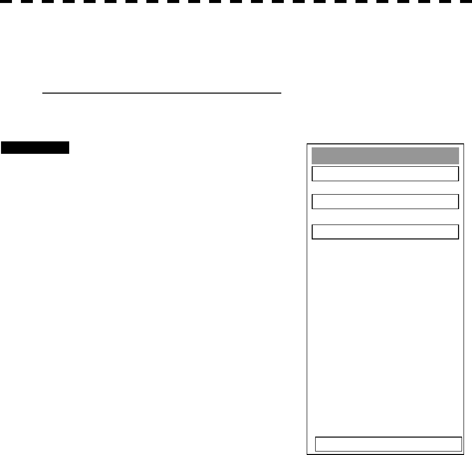
3─133
3.12.2 Erase/Initialize Card Memory (CLR MEM/INIT Card)
Erase saved information from inside the processor.
[I] Erase Mark/Line (CLR Mark/Line Data)
Erase saved mark/line from inside the processor.
Procedures 1 Press [RADAR MENU] key twice.
The Radar Menu will appear.
2 Press [9] key.
The Plot Menu will appear.
3 Press [7] key.
The CLR MEM INT Menu will appear.
4 Press [1] key.
A window will appear to select whether or not
marks/lines should be erased.
1. Erased
2: Cancel
CLR MEM/ INIT Card
1. CLR Mark/Line Data
2.CLR WPT/Route Data
3. Format Card 2
0. EXIT

3─134
3
3.12 Using CARD
[II] Erase Waypoint/Route (CLR WPT/Route Data)
Erase saved WPT/Route from inside the processor.
Procedures 1 Press [RADAR MENU] key twice.
The Radar Menu will appear.
2 Press [9] key.
The Plot Menu will appear.
3 Press [7] key.
The CLR MEM INIT Card Menu will appear.
4 Press [2] key.
The Waypoint/Route Erase Execution window will appear.
1. Erase
2: Cancel
[III] Initialize Card 2 (Format Card 2)
Initialize Card 2.
Procedures 1 Press [RADAR MENU] key twice.
The Radar Menu will appear.
2 Press [9] key.
The Plot Menu will appear.
3 Press [7] key.
The CLR MEM INIT Card Menu will appear.
4 Press [3] key.
The window to select whether or not Card 2 is initialized will appear.
1. Initialize
2: Cancel