Japan Radio NKE2252 25KW X-Band Radar Transceiver User Manual
Japan Radio Co Ltd. 25KW X-Band Radar Transceiver
Contents
- 1. Instruction manual 1 of 3
- 2. Instruction manual 2 of 3
- 3. Instruction manual 3 of 3
Instruction manual 3 of 3

SECTION 9
AFTER-SALES SERVICE

9─1
・・・・・・ When you Request for Repair・・・・・・・・・・・・・・・・・・・・・・・・・・・・・・・
If you suppose the product may be out of order, read the description in Section 8 carefully and
check the suspected point again.
If it is still out of order, you are recommended to stop operation of the equipment and consult with
the dealer from whom you purchased the product, or our branch office in your country or district,
the sales department in our main office in Tokyo.
Repair within the Warranty Period
If any failure occurs in the product during its normal operation in accordance with the
instruction manual, the dealer or JRC will repair free of charge. In case that any failure is
caused due to misuse, faulty operation, negligence or force major such as natural disaster and
fire, the product will be repaired with charges.
Repair after the Warranty Period
If any defective function of the product is recoverable by repair, the repair of it will be made at
your own charge upon your request.
Necessary Information for Repair
☆ Product name, model, manufacturing date and serial number
☆ Trouble conditions (as detailed as possible. Refer to “Radar Failure Check List” in page
9-2. )
☆ Name of company/organization, address and telephone number
・・・・・・ Recommended Maintenance ・・・・・・・・・・・・・・・・・・・・・・・・・・・・・・・
The performance of the product may deteriorate due to the secular change of the parts used in it,
though such deterioration depends upon the conditions of operation.
So checkup and maintenance is recommendable for the product in addition to your daily care.
For maintenance, consult with the near-by dealer or our sales department.
Such maintenance will be made with charges.
For further details of after-sale service, contact the JRC Offices in the list at the
end of this manual.

9─2
AFTER-SALES SERVICE
9
Radar Failure Check List
When placing an order for repair of the product, it is requested that you could confirm the check
items and fill the results and sent the sheet to our contact.
If there is any unclear items, contact the ship on which the product is installed, and give the
correct information on the product.
Ship name: Phone: Fax:
Radar general model name: JMA- Serial No. :
(Write the full model name correctly)
(1) Check the following items in the order of the number, and circle the applicable answer
between YES or NO. If the item cannot be determined as YES or NO, explain in detail in
the item (18), others.
(2) If any of the items (1) to (5) is marked as NO, check the fuse of the product (refer to Section
8.2 and 8.3).
(3) Check the items (4) to (17) while the transmission (TX) is ON.
* Functions mentioned in the items (14), (15) and (17) may be optional, answer is not
necessary.
No. Check Item Result
(1) Power can be turned on. (The lamp on the operation panel is lit) YES NO
(2) A few minutes after powering-on, it will become standby status (TX
Ready). YES NO
(3) When powering-on (or TX ON), CRT displays something (CRT is
lit). YES NO
(4) The scanner rotates at the transmission (TX) ON.
(Check the following items while transmission is ON) YES NO
(5) Current is supplied to the magnetron. (Refer to the instruction
manual) YES NO
(6) Turning is enabled. (Check with the range of 6 NM or more) YES NO
(7) Fixed marker is displayed. YES NO
(8) VRM is displayed. YES NO
(9) While noise is displayed while set at STC and FTC minimum, GAIN
maximum, IR-OFF and range 48 NM. YES NO
(10) Target reflection echo is displayed. YES NO
(11) Sensitivity of reflection echo is normal. YES NO
(12) EBL is displayed. YES NO
(13) Cursor mark moves. YES NO
*(14) GYRO course can be set and normally displayed. YES NO
*(15) LOG speed can be normally displayed. YES NO
(16) ARPA works normally. YES NO
*(17)
If equipped with an interswitch, when switching from the straight
mode (II) to (X), the failures (items marked NO) in the above (1) to
(16), are switched over to the other unit.
YES NO
(18) Others (Error message, etc. )

SECTION 10
DISPOSAL
10.1 DISPOSAL OF THE UNIT ...................10-1
10.2 DISPOSAL OF USED BATTERIES..... 10-2
10.3 DISPOSAL OF USED MAGNETRON . 10-3

10─1
DISPOSAL
10.1 DISPOSAL OF THE UNIT
When disposing of this unit, be sure to follow the local laws and regulations for the place of
disposal.
10─2
10
10.2 DISPOSAL OF USED BATTERIES
WARNING
When disposing of used lithium batteries, be sure to insulate the batteries by
taping the Å and ○ terminals.
Otherwise, heat generation, explosion or a fire may occur.
In this unit, Lithium batteries are used for the following parts:
Radar Processing circuit (CDC-1198): BT1 (Maxell: CR2450)
Do not store used lithium batteries. Dispose of them in accordance with regulations of local
government.
When disposing of used lithium batteries be sure to insulate the batteries by taping the Å and
○ terminals. For disposal of batteries, be sure to follow the local laws and regulations.
For detail, consult with the dealer you purchased the product our business office, or local
government.
-
-

10─3
10.3 DISPOSAL OF USED MAGNETRON
Magnetron is used in the Scanner (NKE-2102/2252/1075A)
When the magnetron is replaced with a new one, return the used magnetron to our dealer or
business office.
For detail, consult with our dealer or business office.

SECTION 11
SPECIFICATIONS
11.1 JMA-5310-6 TYPE RADAR ............................................... 11-1
11.2 JMA-5320-7/9/6HS TYPE RADAR .................................... 11-2
11.3 JMA-5330-12 TYPE RADAR ............................................. 11-3
11.4 SCANNER (NKE-2102)...................................................... 11-4
11.5 SCANNER (NKE-2252-7/9)................................................ 11-5
11.6 SCANNER (NKE-1075A) ................................................... 11-6
11.7 SCANNER (NKE-2252-6HS).............................................. 11-7
11.8 DISPLAY UNIT(NCD-4510)................................................ 11-8
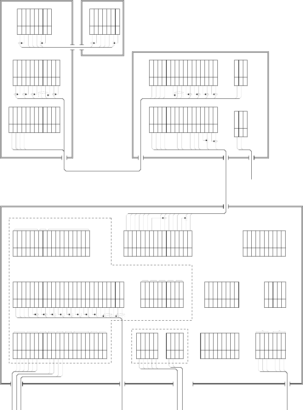
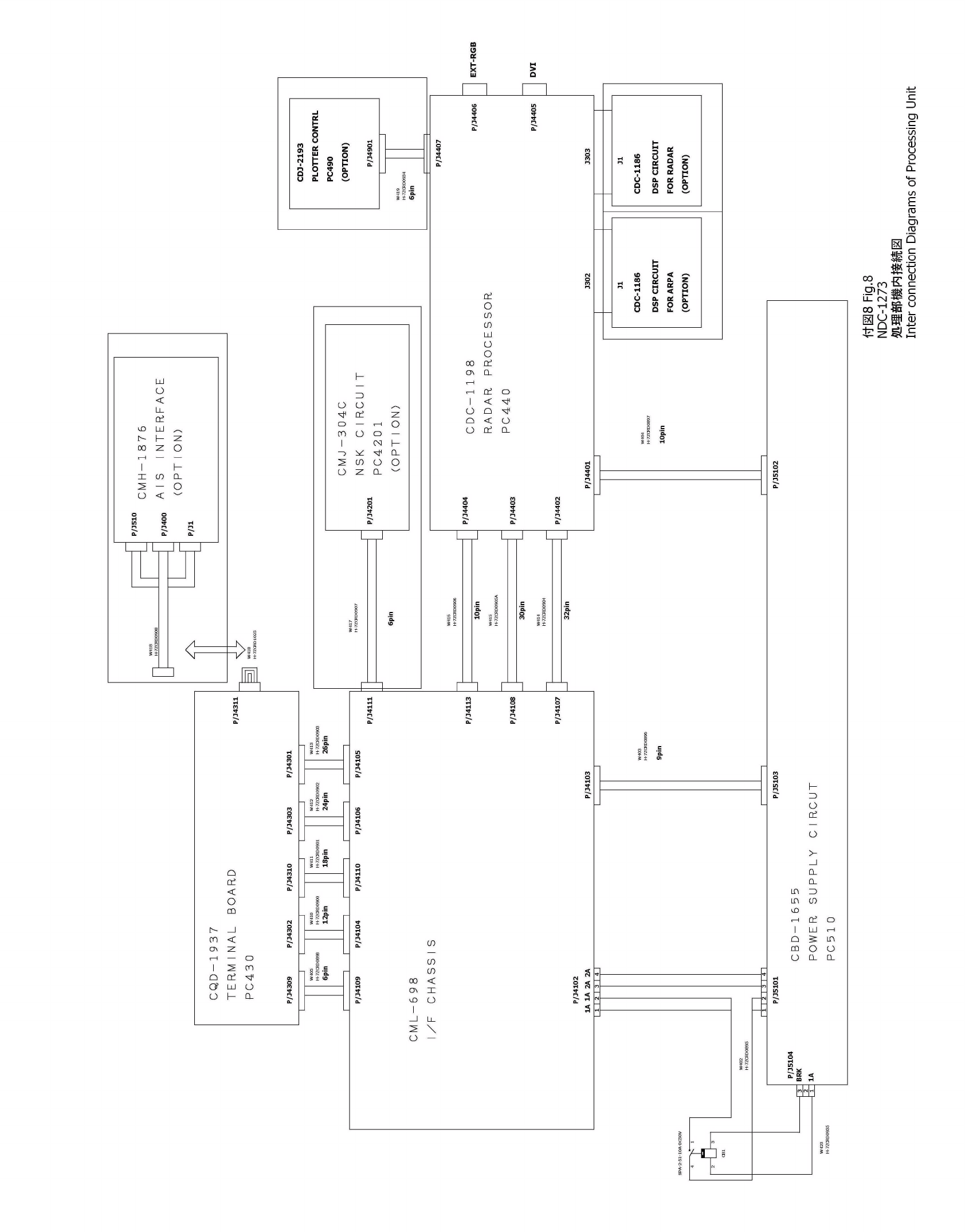
11.9 PROCESSOR UNIT(NDC-1273) ........................................ 11-9
11.10 PLOTTER UNIT................................................................ 11-11
11.11 ARPA-1 (HIGH PERFORMANCE ARPA) ........................ 11-13
11.12 ARPA-2 (NORMAL EDITION ATA) .................................. 11-14
11.13 KEYBOARD UNIT(NCE-7699) ........................................ 11-15
11.14 INPUT ENABLE SIGNAL................................................. 11-16
11.15 OUTPUT ENABLE SIGNAL............................................. 11-17
11.16 STANDARD CONFIGURATION....................................... 11-18
11.17 EQUIPMENT DISTANCE BETWEEN OTHER
INSTRUMENTS ................................................................ 11-19
11.18 OTHERS (OPTION).......................................................... 11-20

11─1
11.1 JMA-5310-6 TYPE RADAR
(1) Type of Emission P0N
(2) Display Color Raster Scan
(3) Screen 18.1-inch Color LCD
Effective diameter of radar display, more than 250 mm
(4) Range Scale 0.125, 0.25, 0.5, 0.75, 1.5, 3, 6, 12, 24, 48, 96nm
(5) Range Resolution Less than 25m
(6) Minimum Detective Range Less than 28m
(7) Range Accuracy Less than 1% of the maximum distance of the range scale in use or
less than 15m whichever is larger
(8) Bearing Accuracy Less than 1°
(9) Bearing Indication Relative Motion mode: Head-up/Course-up/North-up
True Motion mode: Course-up/North-up
(10) Ambient Condition According to IEC60945-4
Temperature
Scanner: -25 to +55℃
(Storage Temperature: -25 to +70℃)
Other Unit except Scanner: -15 to +55℃
Relative Humidity 93% at +40℃
Vibration 2 to 13.2Hz, amplitude ±1mm ±10%
13.2 to 100Hz, Gravity acceleration 0.7m/s2
Velocity of the wind 51.5m/s(100kt)
(11) Power Supply Input +24VDC (Display Unit)
+24VDC (Scanner)
* Display Unit and Scanner correspond to 100VAC/220VAC
when use NBA-3308.
(12) Power Consumption Approx. 300W (In maximum wind velocity)
(13) Power Supply Voltage +24VDC –10/+30% (Display Unit)
Fluctuation +24VDC –10/+30% (Scanner Unit)
(14) Pre-heating Time Approx. Within 1min30sec

11─2
11
11.2 JMA-5320-7/9/6HS TYPE RADAR
(1) Type of Emission P0N
(2) Display Color Raster Scan
(3) Screen 18.1-inch Color LCD
Effective diameter of radar display, more than 250 mm
(4) Range Scale 0.125, 0.25, 0.5, 0.75, 1.5, 3, 6, 12, 24, 48, 96nm
(5) Range Resolution Less than 25m
(6) Minimum Detective Range Less than 28m
(7) Range Accuracy Less than 1% of the maximum distance of the range scale in use or
less than 15m whichever is larger
(8) Bearing Accuracy Less than 1°
(9) Bearing Indication Relative Motion mode: Head-up/Course-up/North-up
True Motion mode: Course-up/North-up
(10) Ambient Condition According to IEC60945-4
Temperature
Scanner: -25 to +55℃
(Storage Temperature: -25 to +70℃)
Other Unit except Scanner: -15 to +55℃
Relative Humidity 93% at +40℃
Vibration 2 to 13.2Hz, amplitude ±1mm ±10%
13.2 to 100Hz, Gravity acceleration 0.7m/s2
Velocity of the wind 51.5m/s (100kt)
(11) Power Supply Input +24VDC (Display Unit)
+24VDC (Scanner)
* Display Unit and Scanner correspond to 100VAC/220VAC
when use NBA-3308.
(12) Power Consumption Approx. 400W (In maximum wind velocity)
(13) Power Supply Voltage +24VDC –10/+30% (Display Unit)
Fluctuation +24VDC –10/+30% (Scanner Unit)
(14) Pre-heating Time Approx. Within 3min

11─3
11.3 JMA-5330-12 TYPE RADAR
(1) Type of Emission P0N
(2) Display Color Raster Scan
(3) Screen 18.1-inch Color LCD
Effective diameter of radar display, more than 250 mm
(4) Range Scale 0.125, 0.25, 0.5, 0.75, 1.5, 3, 6, 12, 24, 48, 96nm
(5) Range Resolution Less than 25m
(6) Minimum Detective Range Less than 28m
(7) Range Accuracy Less than 1% of the maximum distance of the range scale in use or
less than 15m whichever is larger
(8) Bearing Accuracy Less than 1°
(9) Bearing Indication Relative Motion mode: Head-up/Course-up/North-up
True Motion mode: Course-up/North-up
(10) Ambient Condition According to IEC60945-4
Temperature
Scanner: -25 to +55℃
(Storage Temperature: -25 to +70℃)
Other Unit except Scanner: -15 to +55℃
Relative Humidity 93% at +40℃
Vibration 2 to 13.2Hz, amplitude ±1mm ±10%
13.2 to 100Hz, Gravity acceleration 0.7m/s2
Velocity of the wind 51.5m/s(100kt)
(11) Power Supply Input +24VDC (Display Unit)
230VAC, 1Φ, 50/60Hz (Scanner)
* Display Unit correspond to 100VAC/220VAC
when use NBA-3308.
(12) Power Consumption Approx. 100W(+600VA) (In maximum wind velocity)
(13) Power Supply Voltage +24VDC –10/+30% (Display Unit)
Fluctuation 220VAC ±10% (Scanner Unit)
(14) Pre-heating Time Approx. Within 3min

11─4
11
11.4 SCANNER (NKE-2102)
(1) Dimensions Height 440mm´Swing Circle 1910mm
(2) Mass Approx. 31kg
(3) Polarization Horizontal Polarization
(4) Directional Characteristic Horizontal Beam Width: 1.2° (-3dB width)
Vertical Beam Width: 20° (-3dB width)
Sidelobe Level: Below –26dB (within ±10°)
Below –30dB (outside ±10°)
(5) Revolution Approx. 27rpm (Normal)
(6) Peak Power 10kW
(7) Transmitting Frequency 9410 ±30MHz
(8) Transmitting Tube Magnetron [MSF1425B]
(9) Pulse width/Repetition Frequency
Short Middle Long
0.125nm 0.08mS/2250Hz
0.25nm 0.08mS/2250Hz
0.5nm 0.08mS/2250Hz
0.75nm 0.08mS/2250Hz 0.25mS/1700Hz
1.5nm 0.08mS/2250Hz 0.25mS/1700Hz 0.5mS/1200Hz
3nm 0.25mS/1700Hz 0.5mS/1200Hz 0.8mS/750Hz
6nm 0.5mS/1200Hz 0.8mS/750Hz 1.0mS/650Hz
12nm 0.5mS/1200Hz 0.8mS/750Hz 1.0mS/650Hz
24nm 1.0mS/650Hz
48nm 1.0mS/650Hz
96nm 1.0mS/520Hz
(10) Duplexer Circulator + Diode Limiter
(11) Mixer MIC Front End
(12) Intermediate Frequency Amplifier Intermediate Frequency: 60MHz
Band Width: 20MHz(0.08mS)
6MHz(0.25mS)
3MHz(0.5mS, 0.8mS, 1mS)
Gain: More than 90dB
Amplifying Characteristics: Logarithmic Amplifier
(13) Overall Noise Figure 6dB(Average)

11─5
11.5 SCANNER (NKE-2252-7/9)
(1) Dimensions 25kW-7ft: Height 440mm´Swing Circle 2270mm
25kW-9ft: Height 440mm´Swing Circle 2825mm
(2) Mass 25kW-7ft: Approx. 54 kg
25kW-9ft: Approx. 56 kg
(3) Polarization Horizontal Polarization
(4) Directional Characteristics Horizontal Beam Width: 1.0° (7ft, -3dB width)
0.8° (9ft, -3dB width)
Vertical Beam Width 20° (7/9ft, -3dB width)
Sidelobe Level: Below –26dB
(7/9ft, within ±10°)
Below –30dB
(7/9ft, outside ±10°)
(5) Revolution 24rpm (7/9ft, Normal)
(6) Peak Power 25kW ±50%
(7) Transmitting Frequency 9410 ±30MHz
(8) Transmitting Tube Magnetron [M1568B(J)]
(9) Pulse Width/Repetition Frequency
Short Middle Long
0.125nm 0.07mS/2200Hz
0.25nm 0.07mS/2200Hz
0.5nm 0.07mS/2200Hz
0.75nm 0.07mS/2200Hz 0.2mS/2200Hz
1.5nm 0.07mS/2200Hz 0.2mS/2200Hz 0.4mS/1400Hz
3nm 0.2mS/2200Hz 0.4mS/1400Hz 0.8mS/750Hz
6nm 0.4mS/1400Hz 0.8mS/750Hz 1.0mS/650Hz
12nm 0.4mS/1400Hz 0.8mS/750Hz 1.0mS/650Hz
24nm 1.0mS/650Hz
48nm 1.0mS/650Hz
96nm 1.2mS/520Hz
(10) Duplexer Circulator + Diode Limiter
(11) Mixer MIC Front End
(12) Intermediate Frequency Amplifier Intermediate Frequency: 60MHz
Band Width: 20MHz(0.08mS)
6MHz(0.2mS, 0.4mS)
3MHz(0.8mS, 1mS, 1.2mS)
Gain: More than 90dB
Amplifying Characteristics: Logarithmic Amplifier
(13) Overall Noise Figure 6dB(Average)

11─6
11
11.6 SCANNER (NKE-1075A)
(1) Dimensions Height 837mm´Swing Circle 3758mm
(2) Mass Approx. 163kg
(3) Polarization Horizontal Polarization
(4) Directional Characteristics Horizontal Beam Width 12ft: 1.9°
Vertical Beam Width 12ft: 30°
Sidelobe Level: Below –26dB (within ±10°)
Below –30dB (outside ±10°)
(5) Revolution 24/21rpm (60/50Hz)
(6) Peak Power 30kW ±50%
(7) Transmitting Frequency 3050 ±30MHz
(8) Transmitting Tube Magnetron [M1302]]
(9) Pulse Width/Repetition Frequency
Short Middle Long
0.125nm 0.07mS/1900Hz
0.25nm 0.0mS/1900Hz
0.5nm 0.0mS/1900Hz
0.75nm 0.07mS/1900Hz 0.2mS/1900Hz
1.5nm 0.07mS/1900Hz 0.2mS/1900Hz 0.3mS/1900Hz
3nm 0.2mS/1900Hz 0.3mS/1900Hz 0.6mS/1100Hz
6nm 0.3mS/1900Hz 0.6mS/1100Hz 1.2mS/570Hz
12nm 0.3mS/1900Hz 0.6mS/1100Hz 1.2mS/570Hz
24nm 1.2mS/570Hz
48nm 1.2mS/570Hz
96nm 1.2mS/570Hz
(10) Duplexer Circulator + TRHPL
(11) Mixer MIC Front End
(12) Intermediate Frequency Amplifier Intermediate Frequency: 60MHz
Band Width: 20MHz(0.07uS)
6MHz(0.2mS, 0.3mS)
3MHz(0.6mS, 1.2mS)
Gain: More than 90dB
Amplifying Characteristics: Logarithmic Amplifier
(13) Overall Noise Figure 5dB(Average)

11─7
11.7 SCANNER (NKE-2252-6HS)
(1) Dimensions 25kW-6ft: Height 440mm´Swing Circle 1920mm
(2) Mass Approx. 52 kg
(3) Polarization Horizontal Polarization
(4) Directional Characteristics Horizontal Beam Width: 1.2°
Vertical Beam Width 20° (-3dB width)
Sidelobe Level: Below –26dB
(within ±10°)
Below –30dB
(outside ±10°)
(5) Revolution 48rpm (Normal)
(6) Peak Power 25kW ±50%
(7) Transmitting Frequency 9410 ±30MHz
(8) Transmitting Tube Magnetron [M1568B(J)]
(9) Pulse Width/Repetition Frequency
Short Middle Long
0.125nm 0.07mS/2200Hz
0.25nm 0.07mS/2200Hz
0.5nm 0.07mS/2200Hz
0.75nm 0.07mS/2200Hz 0.2mS/2200Hz
1.5nm 0.07mS/2200Hz 0.2mS/2200Hz 0.4mS/1400Hz
3nm 0.2mS/2200Hz 0.4mS/1400Hz 0.8mS/750Hz
6nm 0.4mS/1400Hz 0.8mS/750Hz 1.0mS/650Hz
12nm 0.4mS/1400Hz 0.8mS/750Hz 1.0mS/650Hz
24nm 1.0mS/650Hz
48nm 1.0mS/650Hz
96nm 1.2mS/520Hz
(10) Duplexer Circulator + Diode Limiter
(11) Mixer MIC Front End
(12) Intermediate Frequency Amplifier Intermediate Frequency: 60MHz
Band Width: 20MHz(0.08mS)
6MHz(0.2mS, 0.4mS)
3MHz(0.8mS, 1mS, 1.2mS)
Gain: More than 90dB
Amplifying Characteristics: Logarithmic Amplifier
(13) Overall Noise Figure 6dB(Average)

11─8
11
11.8 DISPLAY UNIT(NCD-4510)
(1) Structure Desk Top Type
(LCD Monitor Unit/Keyboard Unit/Processor Unit Separation Structure)
(2) Screen 18.1-inch Color LCD 1280x1024 dot (SXGA)
(3) Display mode Radar mode
Synthesis mode (Synthesis Radar echo and Coastline)
Plotter mode (Require Plotter Unit (option))
(4) Range Scale 0.125, 0.25, 0.5, 0.75, 1.5, 3, 6, 12, 24, 48, 96nm
(5) Range Marker 0.025, 0.05, 0.1, 0.25, 0.25, 0.5, 1, 2, 4, 8, 16nm
(6) Bearing Indication Rader mode/Synthesis mode
Relative motion: North-up, Course-up, Head-up
True motion: North-up, Course-up
True motion (Plotter mode (Option)): N-up, C-up
(7) Variable Range Maker 2VRM (Digital Display)
VRM unit of Display: nm, km
VRM Range:0.000 to 295nm (0.000 to 547.0km)
(8) Electric Bearing lines 2EBL(Digital Display)
Each EBL can be floating displayed.
EBL unit of Display: 0.1°
EBL Range: 0.000°to 359.9°
Bearing Indication: Relative bearing and True bearing can be switched.
(9) Cursor Target Range, Bearing and Latitude presentation can be possible to move
with trackball.

11─9
11.9 PROCESSOR UNIT(NDC-1273)
(1) Structure Desk Top Type (Horizontal putting and length putting using
combinedly)
(2) Dimensions Height 170mm´Width 300mm´Depth 320mm
(3) Mass Approx. Below 10kg
(4) Tune Method Auto(Bar-graph indicate)
* Manual operation can be adjusted in maintenance mode.
(5) STC (SEA) AUTO/MANUAL
(6) FTC (RAIN) AUTO/MANUAL
(7) Radar Interference Rejection Built-in (The effect can be adjusted by three stages.)
(8) Scan Correlation Function1/2/3, 2 Peak Hold Processing
Automatic change of processing method.
(Target range synchronize/Clutter synchronize)
Rq scan correlation can be done by the addition high performance
signal processing board.
(9) Bearing Marker 360° in 1° digit.
Relative motion: Fixation
True motion: Rewrite at a position correct in every scan.
(10) Heading Line Electronic (Stern Line can be displayed.)
(11) Guard Zone Alarm (Radar Alarm) Invasion, Secession, OFF can be Selected.
With buzzer sound.(Possible to output to External buzzer. )
Zone-1: Ring.(0.1 to 32nm, Relative position)
Zone-2: Arbitrary polygon.(Limitation within range of
display. Longitude and latitude are fixed. )
Number of zone: Can be memorized up to 16 and can be used
simultaneously.
Structure of zone: 16 corner or less.
Automatically acquisition by ATA described in
Section “ARPA”.
(12) Off Center Within 66% of the radius of any range. (Except 96nm)
Can be operated in all mode in relative motion.
Trail is succeed at Off Center mode.
(13) True motion Unit Built-in (Except 96nm)
(14) True motion reset position 66% of radius of any range.
Possible to manual reset.

11─10
11
(15) Twice zoom The zoom center is 66% radius of any range. (Except 0.125nm)
(16) Radar trails indication True motion: (Only true motion)
Relative motion:
True motion trails and relative motion trails can be selected.
Trail time length:
15 sec/30 sec/1 min/3 min/6 min/10 min/15 min/30 min/60
min/Continuous/OFF
Arbitrary trail time length can be displayed at any time.
Possible to display time series trail and continuous trail by color
classification.
Built-in Trail thinning process.
Trail function can be use at true motion reset.
When range is changed, Trail function can be use.
Trail function can be use at Off Center. (Relative motion)
When motion indication and bearing indication changed, Trail
function can be use.(Only true motion trails indication.)
(17) Variety of Pulse width Long/Middle/Short (0.75, 1.5, 3,6,12 nm)
(18) Target enhance 3 stages can be changed.
(19) Correct position When synthesis Radar and Coastline is displayed, position can be
corrected by manually.
(20) Display color Radar echo: 16 stages (Yellow, Green, Orange, Color)
Radar trails: 16 stages (White, Light blue, Green)
Fixed Maker: Monochrome (white)
VRM1/VRM2/EBL1/EBL2: Monochrome (Cyan)
Character/Bearing Marker: 2 stages (White, Green, Orange)
Heading Line/Cursor: Monochrome (White)
Own Ship’s track/Another Ship’s track: 7 stages
Coastline/Isobaths: 16 stages

11─11
11.10 PLOTTER UNIT
(1) Plotter (Normal) (Synthesis mode)
Projection: Mercator projection (Latitude 70 degree or less.)
Scale: Radar synchronize range scale
Own ship trail: Color of 1 stage.
Interval of storage 10/30 sec, 1/3/5/10/30/60 min or
every 1/3/5 nm and OFF
Cursor mark : Storage Capacity 7,000 point
Coastline data : Coastline ROM Card(Option) (ERC, JRC, C-Map NT+)
One selected isobath can be displayed.
Painting out: ON/OFF can be selected.
(2) Plotter (Option) (Synthesis mode)
Projection: Mercator projection (Latitude 70 degree or less.)
Scale: Synchronize range scale
Own ship trail: Color of 7 stages.
Interval of storage: 10/30 sec, 1/3/5/10/30/60 min or every
1/3/5 nm and OFF
Storage capacity of Own ship trail: 7,000 point
Cursor mark: Color of 7 stages
Storage capacity of cursor mark: 20,000 point
Variety of cursor Mark: 19
Event mark: Color of 7 stages
Storage capacity of event mark: Include in cursor mark
Variety of event mark: 3 kinds, (Two kinds can be switched.
/8 form to selection.)
Variety of external event mark: One kind, Monochrome
Line: Color of 7 stage
Storage capacity of line: Include in cursor mark
Variety of line: Solid line, broken line, alternate long and
short dash line
Coast line data: Coast line ROM card (Option)(ERC, JRC, C-Map NT+)
Selected one isoline can be displayed.
Painting out: ON/OFF can be selected.
External memory: Memory card (Option)
Destination and sea route: Destination can be set up to 99 point.
Information of destination: Azimuth, distance and the time
to required destination.
Setting of sea route: 10 sea routes. (10 destination for one
sea route can be set.)
Alarm of sea route: Destination, Secession, Invetion,
Secession
Position compensation: Radar display synchronize range scale coast line by manual.

11─12
11
(3) Plotter (Option) (Synthesis mode)
Projection: Mercator projection (Latitude 85 degree or less.)
Scale: 1/1,000 to 1/10,000,000 are continuously selected.
10 stage can be changed (Preset can be used)
Own ship trail: Color of 7 stages.
Interval of storage: 3/5/10/30 sec, 1/3/5/10/30/60 min
Every 1/3/5 nm and OFF
Storage capacity of Own ship trail: 7,000 point
Cursor mark: Color of 7 stages
Storage capacity of cursor mark: 20,000 point
Variety of cursor Mark: 19
Event mark: Color of 7 stages
Storage capacity of event mark: Include in cursor mark
Variety of event mark: 3 kinds, (Two kinds can be switched.
/8 form to selection.)
Variety of external event mark: One kind, Monochrome
Line: Color of 7 stage
Storage capacity of line: Include in cursor mark
Variety of line: Solid line, broken line, alternate long and
short dash line
Coast line data: Coast line ROM card (Option)(ERC, JRC, C-Map NT+)
Selected one isoline can be displayed.
Painting out: ON/OFF can be selected.
External memory: Memory card (Option)
Own ship trail, another ship trail, cursor mark, event mark,
line, destination, sea route can be memorized.
Destination and sea route: Destination can be set up to 99 point.
Information of destination: Azimuth, distance and the time
to required destination.
Setting of sea route: 10 sea routes. (10 destination for one
sea route can be set.)
Alarm of sea route: Destination, Secession, Invetion,
Secession

11─13
11.11 ARPA-1 (HIGH PERFORMANCE ARPA)
Radar mode, synthesis mode
Manual acquisition, Automatically acquisition(by two of guard ring)
Automatic tracking of 100 targets can be done.
Maximum tracking range: 32nm
Display of tracking data: 6 at the same time. (Can be scroll.)
Naming function: Possible to name by the alphabet up to 8 character to each target.
The range, azimuth, CPA, TCPA, true course, true speed, BCR, BCT of
target can be displayed.
(When naming is displayed, BCR/BCT can’t be displayed.)
Vector display: True/Relative
Past position: Exclusive display and another ship trail.
Alarm of danger ship: Depends on CPA/TCPA setting.
Synthesis mode
Another ship trail: 20 targets. 1000 point per one target can be displayed. (Own ship trail and
marks are another.)
Display color: Color of 7 stages (The display color of each target can be set.)
(The display color of all targets can be set by the batch. In this case, the
display color is one color.)
Interval of storage: 3/5/10/30 sec, 1/3/5/10/130/160 min, 1/3/5/10 nm Possible to storage in
memory card(Option).

11─14
11
11.12 ARPA-2 (NORMAL EDITION ATA)
Radar mode, synthesis mode
Manual acquisition, Automatically acquisition(by two of guard ring)
Automatic tracking of 30 targets can be done.
Maximum tracking range: 32nm
Display of tracking data: 6 at the same time. (Can be scroll.)
Naming function: Possible to name by the alphabet up to 8 character to each target.
The range, azimuth, CPA, TCPA, true course, true speed, BCR, BCT of
target can be displayed.
(When naming is displayed, BCR/BCT can’t be displayed.)
Vector display: True/Relative
Past position: Exclusive display and another ship trail.
Alarm of danger ship: Depends on CPA/TCPA setting.
Synthesis mode
Another ship trail: 20 target.s 1500 point per one target can be displayed. (Own ship trail and
marks are another.)
Display color: Color of 7 stages (The display color of each target can be set.)
(The display color of all targets can be set by the batch. In this case, the
display color is one color.)
Interval of storage: 3/5/10/30 sec, 1/3/5/10/60 min, 1/3/5/10 nm Possible to storage in memory
card(Option).

11─15
11.13 KEYBOARD UNIT(NCE-7699)
(1) Structure Structure of keyboard unit is separate from processor unit.
Desk-Top type
Correspond Flush mount
(2) Switch Gain (Transmit pulse width can be changed by PUSH-SW.)
SEA (AUTO/MANU can be changed by PUSH-SW.)
RAIN (AUTO/MANU can be changed by PUSH-SW.)
MULTI (Adjustment item can be changed by PUSH-SW)
EBL (Floating EBL ON/OFF can be changed by PUSH-SW.)
VRM
Trackball
(3) Operation switch
STBY/OFF (Standby/Power off): Stop transmit, Power off.
TX/OFF (Transmit start/Power off): Start transmit, Power off
PANEL(Brightness of keyboard adjustment): Brightness of keyboard switch adjust.
ALARM ACK(Stop Alarm): Acknowledge and stop alarm.
EBL1(EBL1): Selection display and non-display of EBL1.
EBL2(EBL2): Selection display and non-display of EBL2.
VRM1(VRM1): Selection display and non-display of VRM1.
VRM2(VRM2): Selection display and non-display of VRM2.
RANGE+(Increase display range): Increase display range.
RANGE-(decrease display range): decrease display range.
ACQ(acquisition): ATA target acquisition
TGT DATA(Numeric display): Numeric display of tracking target.
TGT CNCL(Release of selection): Release of selection of tracking target.
MOB(Marker): Turning on and release marker.
ENT(Enter): Left side button of trackball.
CLR/INFO(Release/Information): Right side of trackball.
MAP(Display mode): Selection display and non-display of MAP(NAV
LINE, etc…).
Selection of Rader, Synthesis and Plotter mode.
AZI MODE(Display azimuth): Selection of North-up, Course-Up, Head-Up.
TM/RM(True/Relative Motion): Selection true motion, relative motion.
RR/HL(Fixed ring/Heading Line): Selection display and non-display of fixed ring and
heading line.
OFF CENT(Off Center): Off center operation
GZ ALARM (Guard zone alarm): Setting and release of guard zone.
VECT T/R (True/Relative motion vector): Selection of true motion and relative motion of
vector.
TRAILS (Trails): Selection display and non-display of trails.
Day/Night(Brightness of screen switch): Selection of screen arrangement of color.
FUNC(Function): Selection of signal processing.
USER KEY1(User key1): User assignment key1.
USER KEY2(User key2): User assignment key2.
RADAR MENU(Radar menu): Rader menu.
MARK(MARK): Selection display and non-display of mark.
ATA M E N U ( ATA m e n u ) : ATA me n u.

11─16
11
11.14 INPUT ENABLE SIGNAL
(1) Navigation equipment: NMEA0183
Receive capability sentence.
Longitude/Latitude: GGA>RMC>RMA>GNS/GLL
Waypoint: RMB>BWC(BWR)
COG/SOG: RMC>RMA>VTG
SPEED: VBW
Day/Time information: ZDA
(2) Bearing signal: GYRO-SYNC: 360X, 180X, 90X, 30X. (Require optional NSK
unit)
GYRO-STEP: 360X, 180X, 90X, 30X. (Require optional NSK
unit)
JRC-NSK format (JLR-10)
IEC61162-2 38400bps: HDT
IEC61162-1: HDT>HDG>HDM>VHW
※Can’t be use for ATA.
(3) Speed signal: LOG-SYNC: 360X, 180X,90X, 30X. (Require optional NSK
unit)
LOG-PULSE: 800, 400, 200, 100. (Require optional NSK unit)
(4) External event mark: Contact input by way of terminal board.
(5) Radar buoy: Negative input
(6) Depth: DPT>DBK>DBT>DBS
(7) Water temperature: MTW
(8) Tendency: CUR, JRC format
(9) Direction of wind, velocity of wind: MWV, MWD

11─17
11.15 OUTPUT ENABLE SIGNAL
(1) Slave video Radar video: TIY, VD, BP(2048p), BZ
(2) Navigation information NMEA0183
Radar system data: RSD
Own ship data: OSD
ARPA data: TTM
Target data latitude/longitude: TLL
Alarm: ALR
(3) External alarm Contact output by way of terminal board
(4) External monitor Multi scan monitor, Analog RGB, HD15pin Connector

11─18
11
11.16 STANDARD CONFIGURATION
(1) Scanner 1
(2) Display unit 1 (Processor unit, LCD unit, Keyboard unit)
(3) Equipment cable 10/25kW (Both end was connectors.)
Standard:20m, Option: 30m
30kW (The end of display unit is a connector.)
Display unit to Power supply unit Standard:20m, Option:30m
Power supply unit to scanner Standard:15m, Option:50m(Maximum)
(4) Equipment reserve parts 1
(5) Instruction manual 1 (Japanese or English)

11─19
11.17 EQUIPMENT DISTANCE BETWEEN
OTHER INSTRUMENTS
Maximum Standard
(1) LCD monitor to processor unit 5m 5m
(2) Keyboard unit to processor unit 5m 5m
(3) Scanner to display unit (10/25kw) 30m 20m
(4) Scanner to power supply unit (30kW) 50m 20m
(5) Power supply unit to display unit(30kW) 30m 20m

11─20
11
11.14 OUTPUT ENABLE SIGNAL
11.18 OTHERS (OPTION)
· High performance ARPA unit (Built-in)
· Normal edition ATA unit (Built-in)
· NSK unit (Built-in)
· Plotter (Built-in)
· AIS interface (Built-in)
· Coast line ROM card
· Memory card
· Inter Switch
APPENDIX
INTER-SWITCH (Option)
NQE-3141
Instruction Manual
1. Overview .............................................................A-1
1.1 Overview ····················································A-1
1.2 Configuration·············································A-1
2. Operation ............................................................A-2
2.1 Operation Flow ··········································A-2
2.2 Inter Switch Menu ·····································A-3
2.2.1 Switching an Inter-Switch Pattern·······A-4
2.3 Reading Inter-switch Patterns ···············A-10
2.4 Saving Inter-switch patterns·················· A-11
2.5 Naming Indicators···································A-12
2.6 Naming Scanners····································A-13
3. Reference..........................................................A-14
A - 1
1. OVERVIEW
1.1 OVERVIEW
The inter-switch enables switching connections between multiple radar indicators that are
installed on a bridge and multiple antennas of different characteristics.
The NQE-3141 switches connections between multiple indicators and multiple transceivers/
scanners (referred to as MTR henceforth) on the JMA-5300 Series radar equipment.
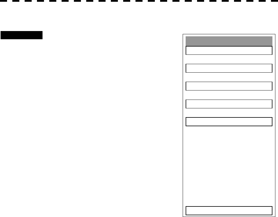
1.2 CONFIGURATION
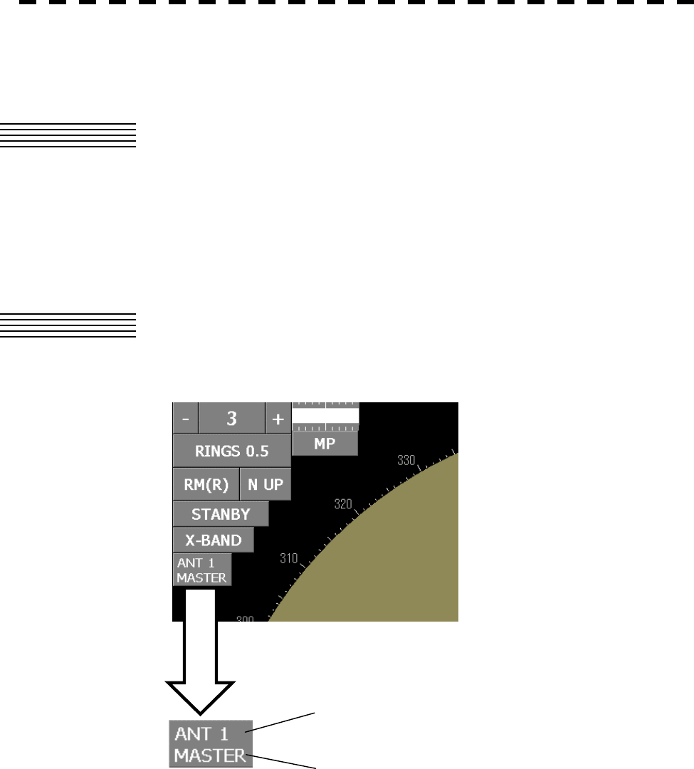
Connections can be switched easily using the button on the screen.
c indicates the channel number that is connected.
d indicates MASTER or SLAVE.
When MASTER is displayed, the indicator can control the scanner.
When SLAVE is displayed, the indicator cannot control the scanner.
In SLAVE mode, transmission/stop and pulse width switching cannot be changed. The usage
range is also restricted.
c
d
Button on the screen
A - 2
APPENDIX
APPENDI
X
Click on .
Change the indicator to which the scanner is connected and click on
.
Click on the switch on the top-left corner of the screen.
When the switch on the top-left corner of the screen is set to ,
set it to by clicking on the left button.
2. OPERATION
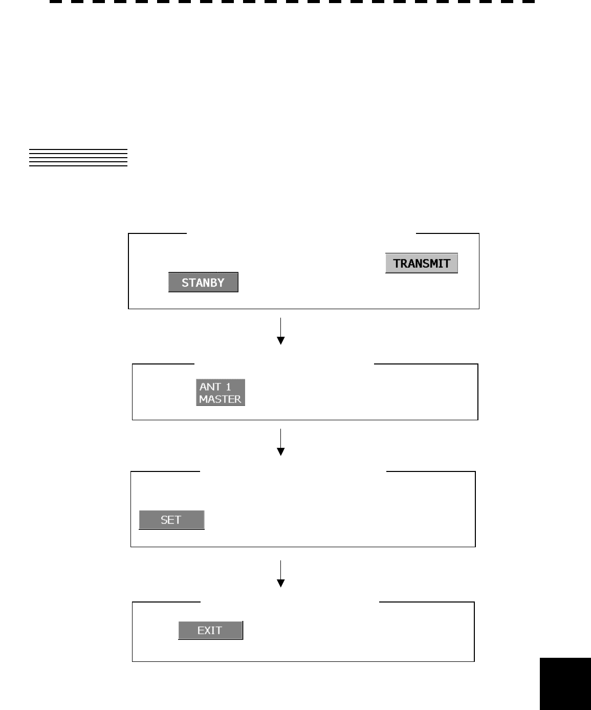
When switching an inter-switch pattern, set the inter-switch to STANDBY and operate the
switches on the indicator panel according to the following flow.
2.1 OPERATION FLOW
Flow from opening to the closing of the menu
[Close the Inter Switch menu]
[Set the inter-switch to a standby state]
[Switch the inter-switch pattern]
[Open the Inter Switch menu]
A - 3
0EXIT
INFORMATION
DOWNLOAD
SET
X-BAND
10kW
X-BAND
SLAVE
No1
MASTER No2 No1
No2
To close this menu, Click EXIT button or (0) key.
25kW
INTER SWITCH
TRX
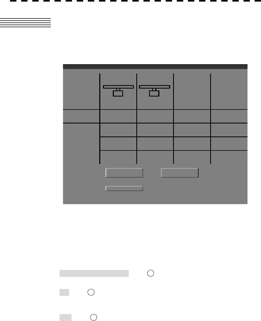
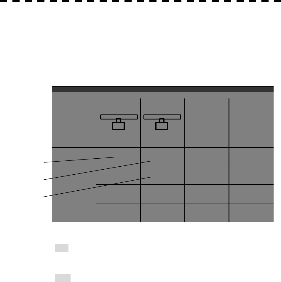
2.2 INTER SWITCH MENU
The Inter Switch menu can be opened only when the radar is in a standby mode. The Inter
Switch menu can be opened during transmission, however, in this case, transmission
automatically stops and the radar is set to a standby mode.
When the button on the screen is clicked on, the Inter Switch menu is displayed as shown above.
c indicates the scanner format.
d Indicates the master indicator and e indicates the slave indicator.
Functions of the three switches that are provided at the bottom of the Inter Switch menu are
described below.
• DOWNLOAD INFORMATION button ( A)
Updates information.
• SET button ( B)
Sets a pattern at switching of an inter-switch pattern. See Section 2.2.1, “Switching an
Inter-Switch Pattern” for details.
• EXIT button ( C)
Closes the Inter Switch menu.
A - 4
APPENDIX
APPENDI
X
2.2.1 Switching an Inter-Switch Pattern····················································
This section uses an example that controls two indicators and two scanners.
[1] Switching two indicators (cross connection)
Procedure
1. Press the [RADAR MENU] key twice.
Press the [6] key.
The Inter Switch Setting menu is opened.
Press the [1] key.
The Change Pattern screen is displayed.
* Indicators can also be switched by using the 2-9P radar
screen j button.
Inter Switch Setting
1. Change Pattern
2. Load Pattern >
3. Save Pattern >
4. Input IND. Name >
5. Input TRX Name >
0. EXIT
A - 5
X-BAND
10kW
X-BAND
No2
MASTER No1 No2
SLAVE
25kW
INTER SWITCH
TRX
No1
c
d
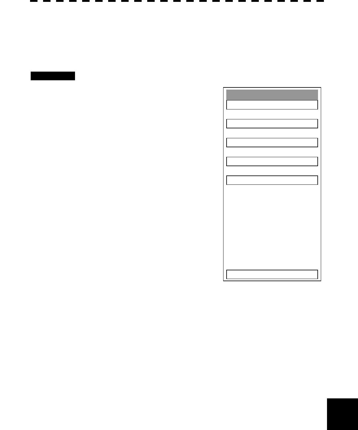
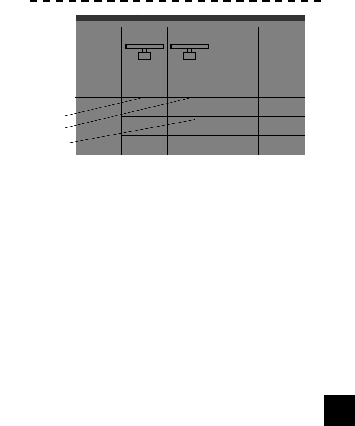
2. Set the cursor to the panel of the indicator to be switched and press the [ENT]
key.
Select the panel in which the indicator name is displayed within the bold frame as shown above. Panels
of the indicators that are not displayed cannot be selected.
Example: Set the cursor to panel c and press the [ENT] key.
The panel of the selected indicator is displayed in reverse video.
A - 6
APPENDIX
APPENDI
X
3. Set the cursor to the panel of another indicator and press the [ENT] key.
Example: Set the cursor to panel d and press the [ENT] key.
Indicator d and indicator c are switched.
The names of indicators c and d are switched as follows.
4. Click on SET at the bottom of the Inter Switch menu.
The inter-switch pattern switching is set.
5. Click on EXIT at the bottom of the Inter Switch menu.
The Inter Switch menu is closed.
25kW
INTER SWITCH
TRX
No1
MASTER No2 No1
SLAVE
No2
X-BAND
10kW
X-BAND
c
d
A - 7
Inter Switch Setting
1. Change Pattern
2. Load Pattern >
3. Save Pattern >
4. Input IND. Name >
5. Input TRX Name >
0. EXIT
[II] Setting one indicator as a slave of another indicator (slave connection)
Procedure
1. Press the [RADAR MENU] key twice.
Press the [6] key.
The Inter Switch Setting menu is opened.
Press the [1] key.
The Change Pattern screen is displayed.
* Indicators can also be switched by using the 2-9P radar
screen j button.
A - 8
APPENDIX
APPENDI
X
X-BAND
10kW
X-BAND
No2
MASTER No1 No2
SLAVE
25kW
INTER SWITCH
TRX
No1
c
d
e
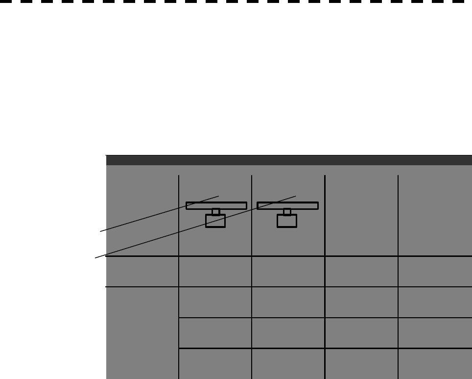
2. Set the cursor to the panel of the indicator to be set as a slave and press the
[ENT] key.
Select the panel in which the indicator name is displayed within the bold frame as shown above. Panels
of the indicators that are not displayed cannot be selected.
Example: Set the cursor to panel c and press the [ENT] key.
The panel of the selected indicator is displayed in reverse video.
A - 9
25kW
INTER SWITCH
TRX
No1
MASTER No2
SLAVE
No1
No2
X-BAND
10kW
X-BAND
c
d
e
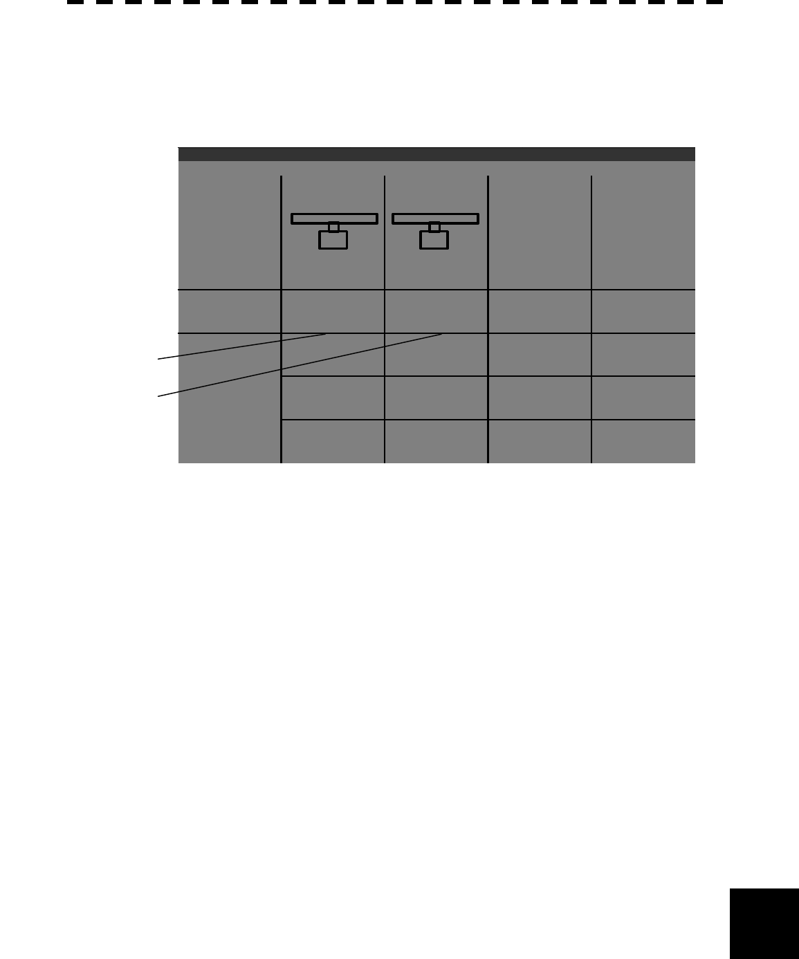
3. Set the cursor to the panel under the indicator that is to be set as a master and
press the [ENT] key.
Example: Set the cursor to panel e and press the [ENT] key.
Indicator c moves to position e.
Indicator c is set to a slave of indicator d as shown below.
4. Click on SET at the bottom of the Inter Switch menu.
The inter-switch pattern switching is set.
5. Click on EXIT at the bottom of the Inter Switch menu.
The Inter Switch menu is closed.

A - 10
APPENDIX
APPENDI
X
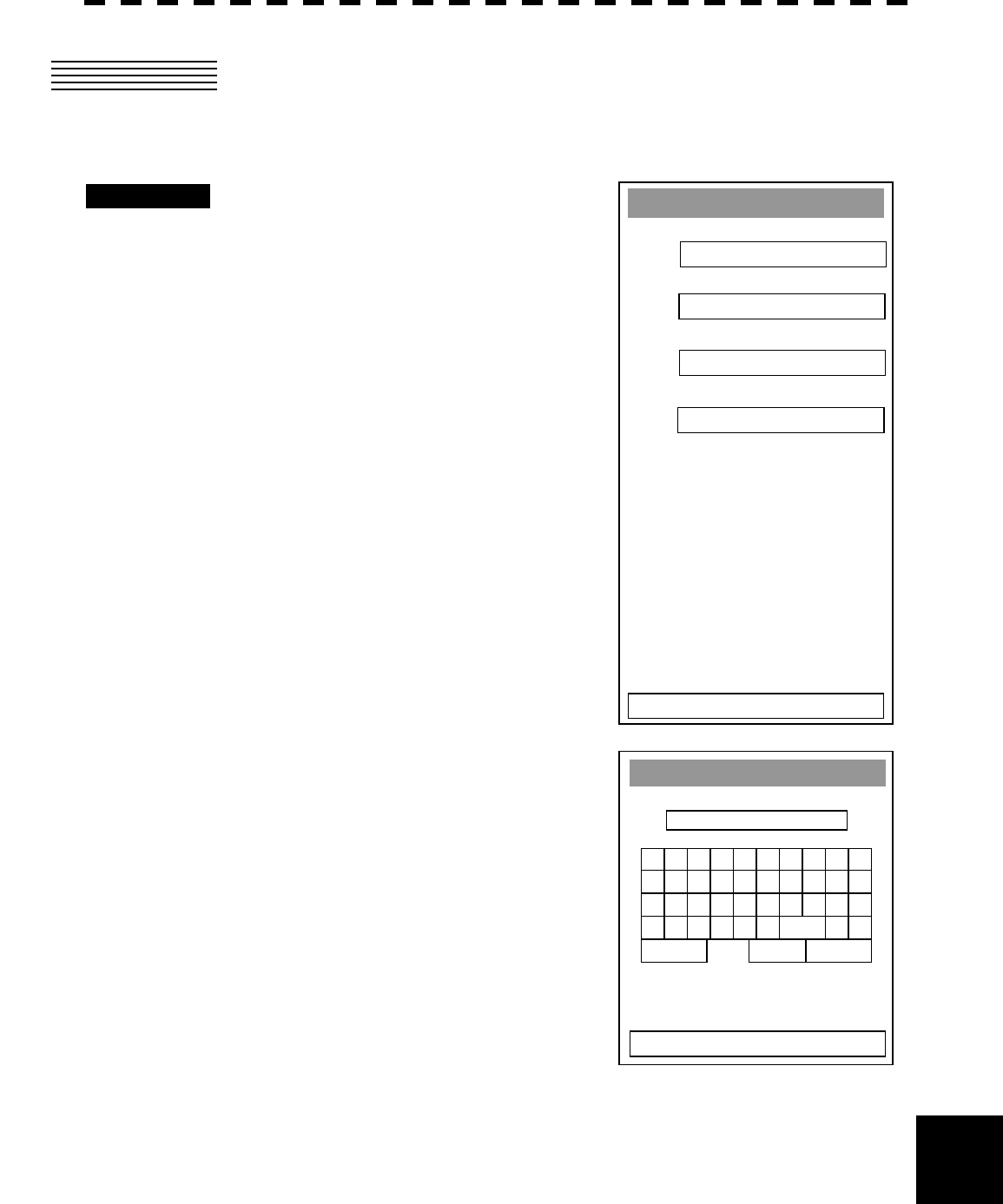
2.3 READING INTER-SWITCH PATTERNS
Inter-switch patterns that have been saved can be read.
Procedure
1. Press the [RADAR MENU] key twice.
Press the [6] key.
The Inter Switch Setting menu is opened.
Press the [2] key.
The Load Pattern screen is displayed.
2. Select the number of the file to which the
pattern is to be loaded using any of the
numeric keys [1] to [5].
The loaded inter-switch pattern is reflected.
Load Pattern
1.
2.
3.
4.
5.
0. EXIT
9. NEXT >
A - 11
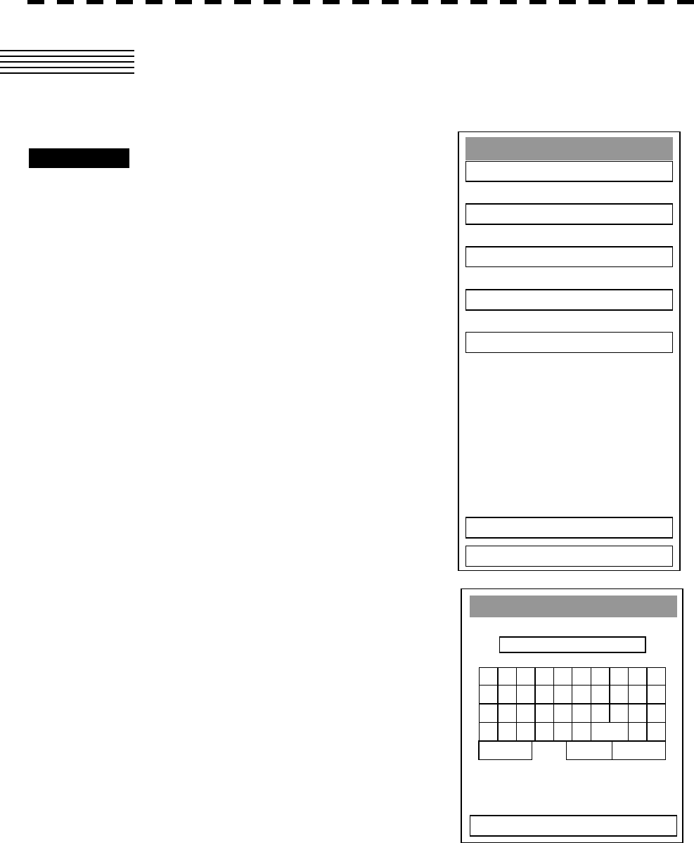
2.4 SAVING INTER-SWITCH PATTERNS
Inter-switch patterns can be saved.
Procedure
1. Press the [RADAR MENU] key twice.
Press the [6] key.
The Inter Switch Setting menu is opened.
Press the [3] key.
The Save Pattern screen is displayed.
2. Select the number of the file in which the
pattern is to be saved using any of numeric
keys [1] to [5].
An alphanumeric key screen is displayed.
3. Enter a name using alphanumeric keys and
press the ENT button.
The data is saved under the file name that was entered.
9. NEXT >
Save Pattern
1.
2.
3.
4.
5.
0. EXIT
1 2 34 5 6 7 8 90
B C DE F G H I JA
L M N O P Q R S TK
V W X Y Z SP < >U
DEL ENT BS
Save Pattern
EXIT
A - 12
APPENDIX
APPENDI
X
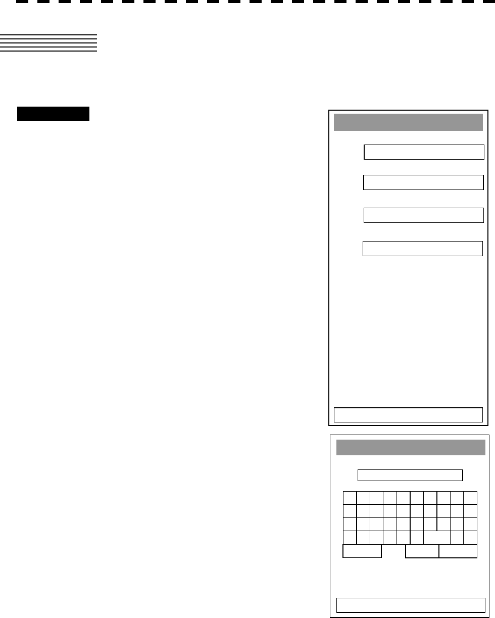
2.5 NAMING INDICATORS
Names can be assigned to indicators.
Procedure
1. Press the [RADAR MENU] key twice.
Press the [6] key.
The Inter Switch Setting menu is opened.
Press the [3] key.
The Input IND. Name screen is displayed.
2. Select the number of the indicator to be named
using any of numeric keys [1] to [4].
An alphanumeric key screen is displayed.
3. Enter a name using alphanumeric keys and
press the ENT button.
The name that was entered is reflected in the indicator.
* Up to four indicators can be named.
1 2 34567890
B C DE F G H I JA
L M N O P Q R S TK
V W X Y Z SP < >U
DEL ENT BS
No.1
EXIT
Input IND. Name
1. No.1
2. No.2
3. No.3
4. No.4
0. EXIT
IND.1
IND.2
IND.3
IND.4
A - 13
2.6 NAMING SCANNERS
Names can be assigned to scanners.
Procedure
1. Press the [RADAR MENU] key twice.
Press the [6] key.
The Inter Switch Setting menu is opened.
Press the [4] key.
The Input TRX Name screen is displayed.
2. Select the number of the scanner to be named
using any of numeric keys [1] to [4].
An alphanumeric key screen is displayed.
3. Enter a name using alphanumeric keys and
press the ENT button.
The name that was entered is reflected in the scanner.
* Up to four scanners can be named.
1 2 34 5 6 7 8 90
B C DE F G H I JA
L M N O P Q R S TK
V W X Y Z SP < >U
DEL ENT BS
No.1
EXIT
Input TRX Name
1. No.1
2. No.2
3. No.3
4. No.4
0. EXIT
T
RX1
T
RX2
T
RX3
T
RX4

A - 14
APPENDIX
APPENDI
X
3. REFERENCE
Preheating time required after pattern switching
A preheating time is required in some cases as indicated below after completion of an inter-switch
pattern switching since the preheating time varies according to the connection state between the
scanner (MTR) and the indicator before switching.
This delay is to protect the electron tube that delivers radiowaves.
(a) Connection was not changed to a new connection state: No preheating required
(b) Connection was changed to a new connection state and a scanner has been used before the
change: No preheating required
(c) Connection was changed to a new connection state and a scanner has not been used before
the change: Preheating required
Notes on pattern switching
Pattern switching may not be enabled immediately after completion of the previous pattern
switching.
This is because it takes some time to prepare for the next switching after completion of the
previous pattern switching. Wait for several seconds before starting the next pattern switching.

A - 15
Notes on master/slave connection mode
Master/slave connection refers to the connection where the indicator that is connected to a scanner
is defined as a master and the indicator that is connected to the master indicator is defined as a
slave indicator.
A slave indicator cannot be set to a transmission mode unless the master indicator is in a
transmission mode. When the mode of a master indicator is changed from a transmission mode
to a standby mode, “MTR ST-BY” is displayed in the message area and an alarm sound is emitted.
A slave indicator is not capable of tuning control. Tuning is controlled by a master indicator.
“SLAVE” is displayed on the tuning display at the top-left corner of the screen.
The range change of a slave indicator is restricted by the range of the master indicator. In
principle, the range of a slave indicator cannot exceed the range of the master indicator.
However, some range may be greater than the range of the master indicator if it is within the same
transmission pulse width/transmission pulse rate.
Setting at installation
The inter-switch must be installed according to the installation guide that is provided separately.
The setting tables are provided below.
A - 16
APPENDIX
APPENDI
X
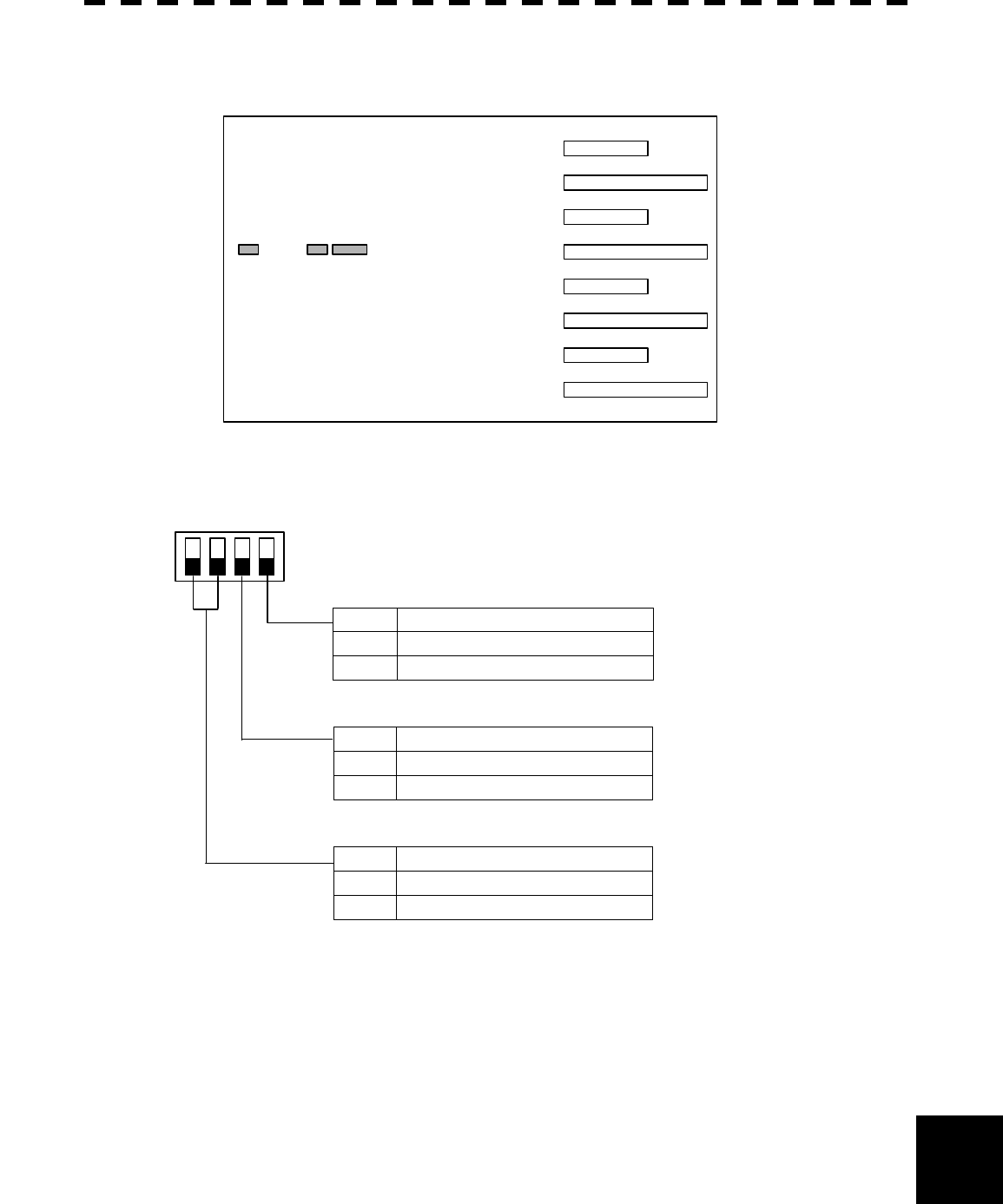
• Setting the inter-switch circuit (CCL-304)
The contents of DIP switches SW11, SW12, and SW13 are shown below.
SW 11 SW 13 SW 12
Inter-switch circuit PCB
CCL-304
(1) Setting SW11 (extension mode, master/slave setting)
1234
ON
OFF
Extension mode setting
4 Contents
ON Extension mode
OFF Normal mode
Master/Slave setting
3 Contents
ON Slave
OFF Master
Unused
1, 2 Contents
ON Unused
OFF Unused
Set the mode to OFF when
connecting 4 indicators or less.
Set the mode to ON when using
the ISW circuit board on the slave
side in extension mode.
N
ormally set to OFF.
A - 17
(2) Setting SW12 (radar connection setting)
1234
ON
OFF
5768
Radar connection setting
ON No.1 indicator connected
1
OFF No.1 indicator not connected
2 ON No.1 Scanner connected
OFF No.1 Scanner not connected
ON No.2 indicator connected 3
OFF No.2 indicator not connected
ON No.2 Scanner connected 4
OFF No.2 Scanner not connected
ON No.3 indicator connected 5
OFF No.3 indicator not connected
ON No.3 Scanner connected 6
OFF No.3 Scanner not connected
ON No.4 indicator connected 7
OFF No.4 indicator not connected
ON No.4 Scanner connected 8
OFF No.4 Scanner not connected
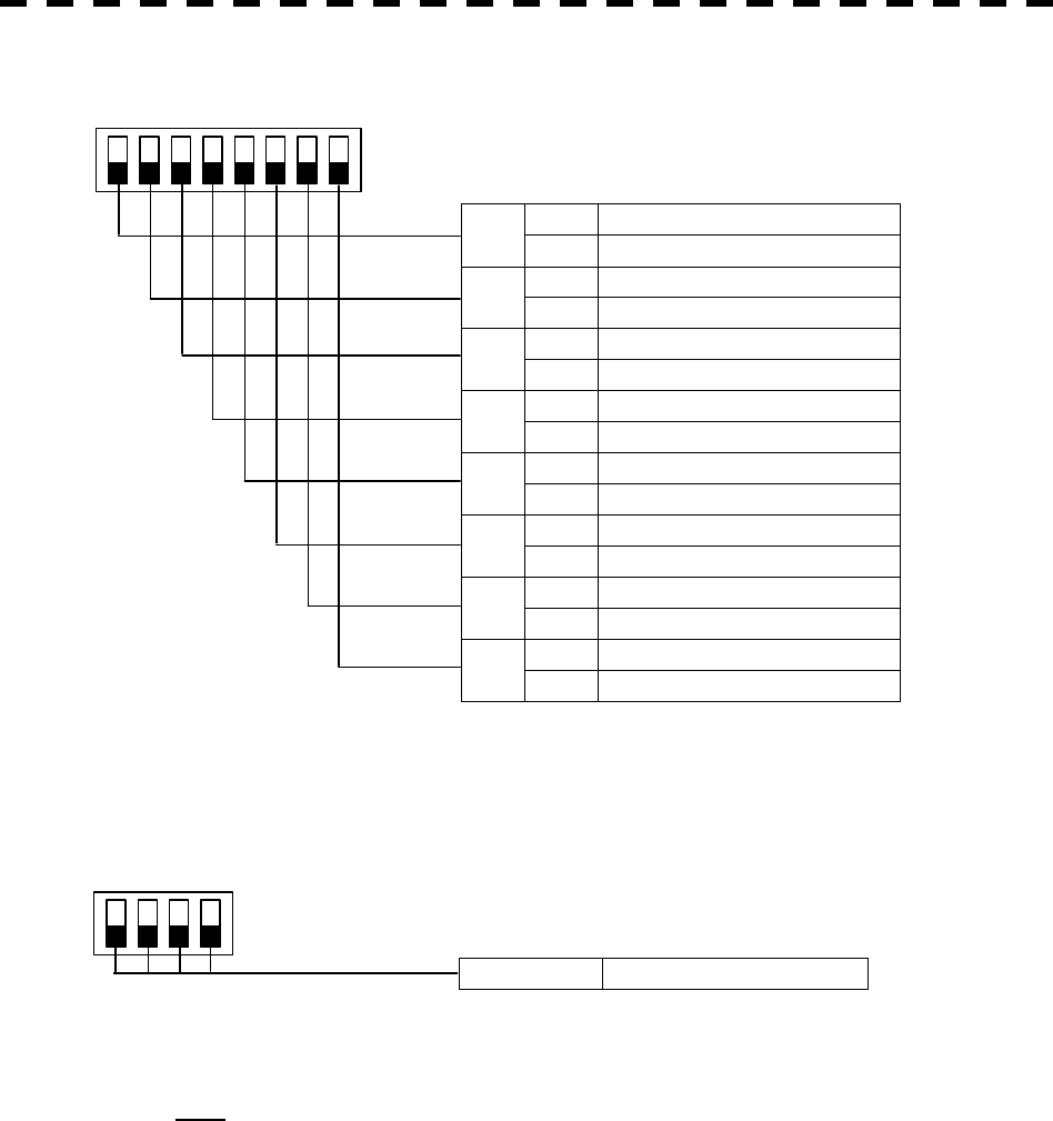
(3) SW13 (Unused)
1234
ON
OFF
1, 2, 3, 4 Unused (all OFF)
Note Before setting the DIP switches of the ISW circuit, ensure that safety procedures are
followed by referencing the Installation Guide.
MIC IF AMP BPF LOG
AMP
LOG
AMP MIX
TUNE
indicater
DAC
LO Control
BW Control
CPUPower Supply
HV
+15V
+8V
-7V
Filter
Power Supply
P12V
+12V
-12V
+5V
+3.3V
buffer
ISW
SEL
TI MTR+/- VD BP/BZ
Relay
BP/BZ
VD
TI
MTR+/-
PWRCNT
ADC
ISW unit
BP/BZ
VD
TI
Signal proc ASIC
STC/FTC/CFAR
IR/AVE/GZ alarm
DSP
radar
DSP
ARPA
option
option
sweep memory
Radar draw ASIC
Scan convert
Scan correlation
Trail process
Radar echo
Radar trails
Frame
sub
CPU
MULTI RAIN SEA GAIN
EBL VRM
Encoder
CPU
TrackBall
Buzer Key matrix
RS422
I/F
PWR
SW
RS485
I/F
RS485
I/F
P12V
+12V
+5V
MTR+/-
PWRCNT
PWRCNT
NSK
unit
option
NMEA
I/F
SEL
RS232C
I/F
RS422
I/F
Main CPU
comunication
User I/F
Main Control
SDRAM FROM
work program
+12V
LDI
RGB
I/F
SIO
SIO
NMEA
I/F
18.1inch LCD
AnalogRGB
DC24V
-10%
GYRO
LOG
GPS
compas
GPS
+12V
PC
32bit bus
Monitor Unit NWZ-147
Keyboard Unit NCE-7699
Scanner Unit NKE-2102/2252
Processor Unit NDC-1273
External
Display
NMEA
I/F
SIO
SIO
NMEA
I/F
NAV
NAV
SRAM
Back up
memory
Graphics ASIC
MAP draw
Graphics draw
MAP
Graphics
Frame
memory
32bit bus
+30%
Radiater
Rotary
Joint
Circu-
later
DL
MAG
Pulse
Trans
SE
Motor
Motor
Cont.
TX
Cont.
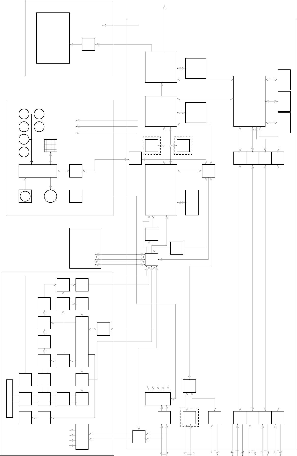
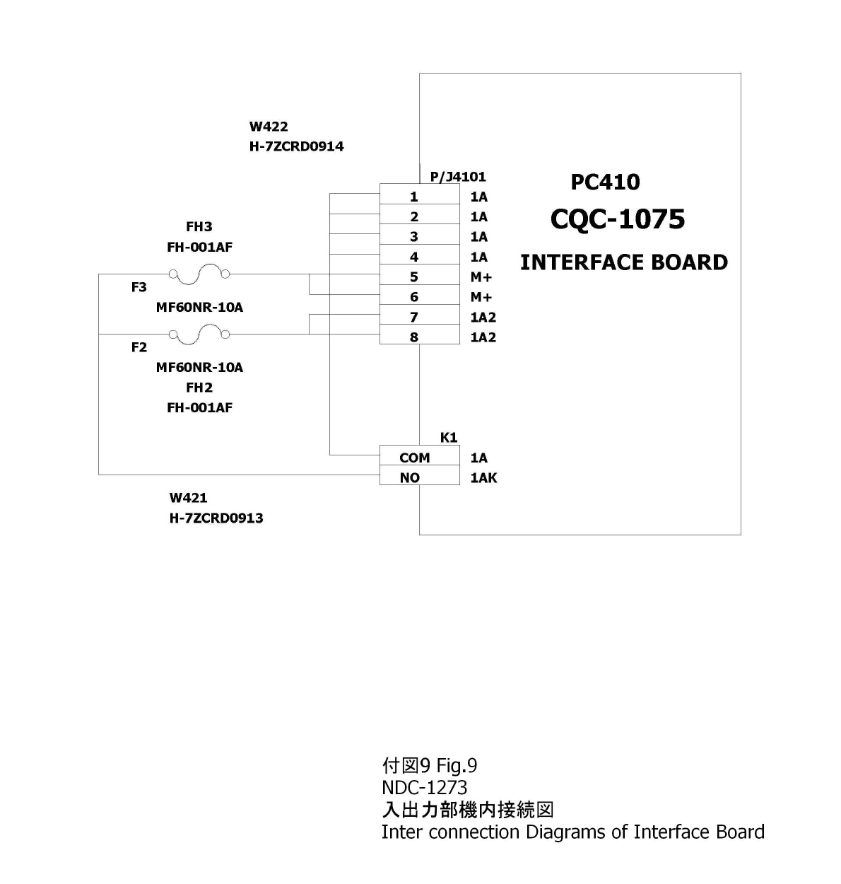
付図 1 Fi
g
.1
JMA-5310-6/5320-7/9
レーダー装置回路動作説明図
Block Diagrams of RADAR JMA-5310-6/5320-7/9
Radiater
Rotary
Joint
Circu-
later
DL MIC
MAG
Pulse
Trans
SE
Motor
Motor
Cont. IF AMP BPF LOG
AMP
LOG
AMP MIX
TUNE
indicater
DAC
TX
Cont.
LO Control
BW Control
CPUPower Supply
HV
+15V
+8V
-7V
Filter
Power Supply
P12V
+12V
-12V
+5V
+3.3V
buffer
ISW
SEL
TI MTR+/- VD BP/BZ
Relay
BP/BZ
VD
TI
MTR+/-
PWRCNT
ADC
ISW unit
BP/BZ
VD
TI
Signal proc ASIC
STC/FTC/CFAR
IR/AVE/GZ alarm
DSP
radar
DSP
ARPA
option
option
sweep memory
Radar draw ASIC
Scan convert
Scan correlation
Trail process
Radar echo
Radar trails
Frame
sub
CPU
MULTI RAIN SEA GAIN
EBL VRM
Encoder
CPU
TrackBall
Buzer Key matrix
RS422
I/F
PWR
SW
RS485
I/F
RS485
I/F
P12V
+12V
+5V
MTR+/-
PWRCNT
PWRCNT
NSK
unit
option
NMEA
I/F
SEL
RS232C
I/F
RS422
I/F
Main CPU
comunication
User I/F
Main Control
SDRAM FROM
work program
+12V
LDI
RGB
I/F
SIO
SIO
NMEA
I/F
18.1inch LCD
AnalogRGB
DC24V
-10%
GYRO
LOG
GPS
compas
GPS
+12V
PC
32bit bus
Monitor Unit NWZ-147
Keyboard Unit NCE-7699
Scanner Unit NKE-1075
Processor Unit NDC-1273
External
Display
NMEA
I/F
SIO
SIO
NMEA
I/F
NAV
NAV
SRAM
Back up
memory
Graphics ASIC
MAP draw
Graphics draw
MAP
Graphics
Frame
memory
32bit bus
+30%
AC220V
-10%
+10%
50/60Hz
JUNCTION UNIT
NQE-3151
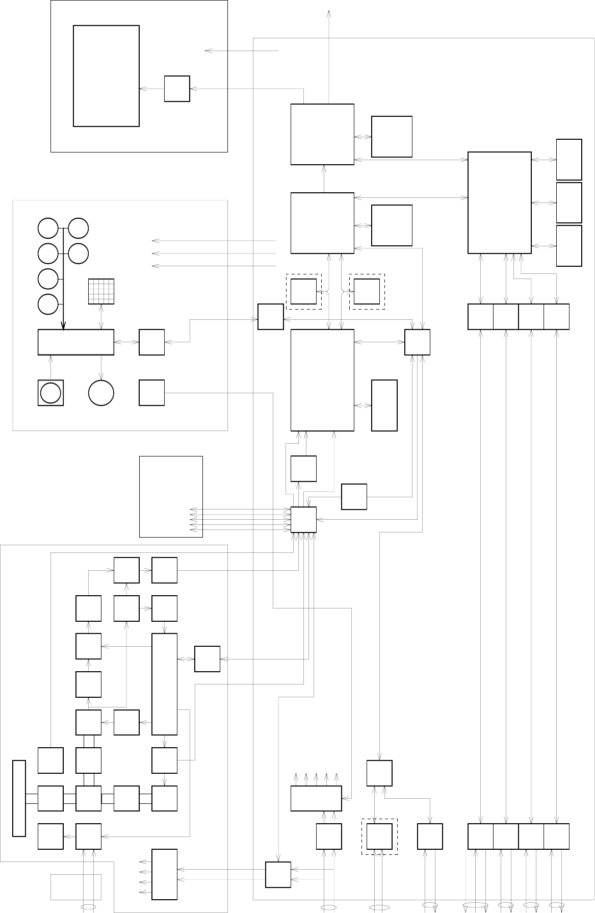
付図 2 Fi
g
.2
JMA-5330-12
レーダー装置回路動作説明図
Block Diagrams of RADAR JMA-5330-12
付図 3 Fi
g
.3
JMA-5310-6
盤間配線図
T
erminal Dia
g
rams of JM
A
-5310-6
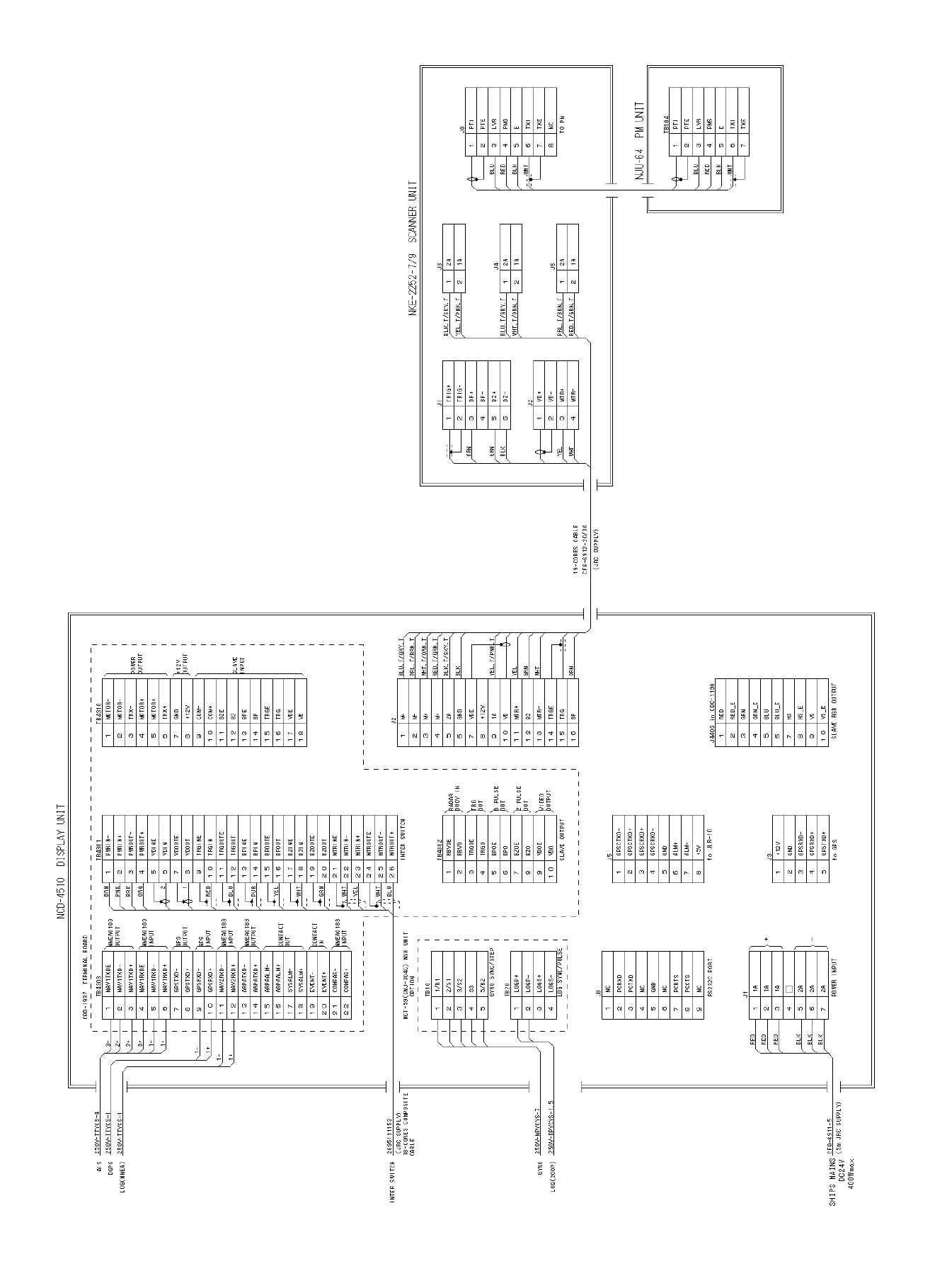
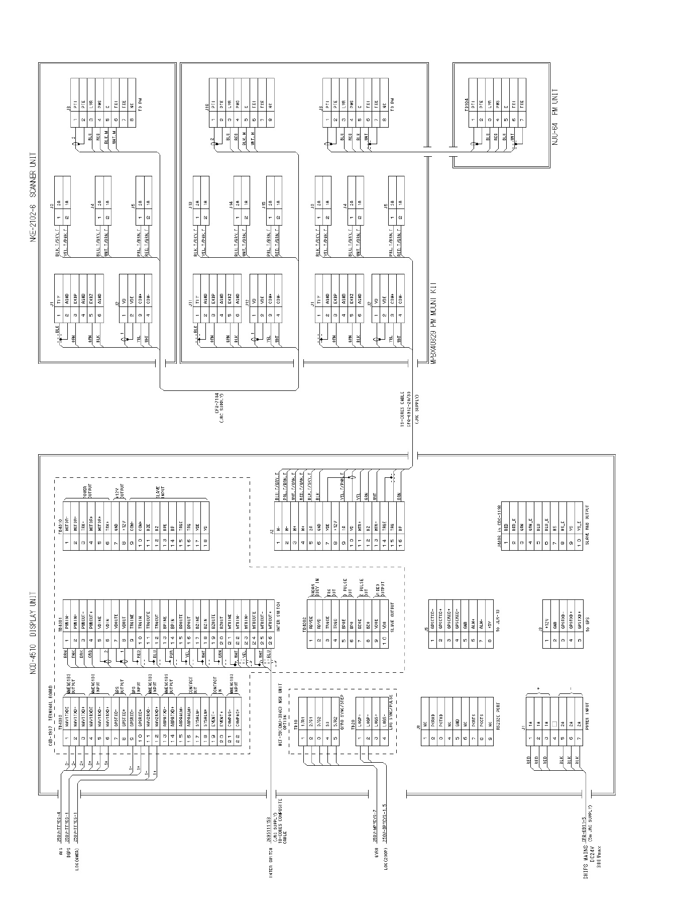
付図 4 Fi
g
.4
JMA-5320-7/9
盤間配線図
T
erminal Dia
g
rams of JM
A
-5320-7/9
1 PWRIN-
2 PWRIN+
3 PWROUT-
4 PWROUT+
5 VDINE
6VDIN
7 VDOUTE
8 VDOUT
9 TRGINE
10 TRGIN
11 TRGOUTE
12 TRGOUT
13 BPINE
14 BPIN
15 BPOUTE
16 BPOUT
17 BZINE
18 BZIN
19 BZOUTE
20 BZOUT
21 MTRINE
22 MTRIN-
23 MTRIN+
24 MTROUTE
25 MTROUT-
26 MTROUT+
TB4301
MOTOR-
MOTOR-
TRX-
MOTOR+
MOTOR+
TRX+
GND
+12V
COM-
COM+
BZE
BZ
BPE
BP
TRGE
TRG
VDE
VD
1
2
3
4
5
6
7
8
9
10
11
12
13
14
15
16
17
18
TB4310
NAV1TXDE
NAV1TXD-
NAV1TXD+
NAV1RXDE
NAV1RXD-
NAV1RXD+
GPSTXD-
GPSTXD+
GPSRXD-
GPSRXD+
NAV2RXD-
NAV2RXD+
ARPATXD-
ARPATXD+
ARPAALM-
ARPAALM+
SYSALM-
SYSALM+
1
2
3
4
5
6
7
8
9
10
11
12
13
14
15
16
17
18
TB4303
EVENT-
19
EVENT+
20
COMPAS-
21
COMPAS+
22
RBVDE
RBVD
TRGOE
TRGO
BPOE
BPO
BZOE
BZO
VDOE
VDO
1
2
3
4
5
6
7
8
9
10
TB4302
1A
1A
1A
2A
2A
2A
1
2
3
4
5
6
7
J1
M-
M-
M+
M+
2A
GND
VDE
+12V
1A
VD
MTR+
BZ
MTR-
TRGE
TRG
BP
1
2
3
4
5
6
7
8
9
10
11
12
13
14
15
16
J2
GPSCTXD-
GPSCTXD+
GPSCRXD+
GPSCRXD-
GND
ALM+
ALM-
+5V
1
2
3
4
5
6
7
8
J5
+12V
GND
GPSRXD-
GPSRXD+
GPSTXD+
1
2
3
4
5
J3
NC
PCRXD
PCTXD
NC
GND
NC
PCRTS
PCCTS
NC
1
2
3
4
5
6
7
8
9
J8
1/R1
2/S1
3/S2
S3
5/R2
1
2
3
4
5
TB10
LOGP+
LOGP-
LOGS+
LOGS-
1
2
3
4
TB20
NCT-59(CMJ-304C) NSK UNIT
to JLR-10
to GPS
CQD-1937 TERMINAL BOARD
RED
RED
RED
BLK
BLK
BLK
+
-
CFQ-6911-5
RS232C PORT
POWER INPUT
INTER SWITCH
SLAVE OUTPUT
GYRO SYNC/STEP
LOG SYNC/PULSE
PTI
PTE
LVR
PMS
GND
TXI
TXE
NC
1
2
3
4
5
6
7
8
J8
TO PM
PTI
PTE
LVR
PMS
GND
TXI
TXE
1
2
3
4
5
6
7
TB104
BLU
RED
BLK
WHT
BLU
RED
BLK
WHT
NJU-63 PM UNIT
NKE-1075/A SCANNER UNIT
BLU.T/GRY.T
PRL.T/BRN.T
WHT.T/ORN.T
RED.T/GRN.T
BLK.T/SKY.T
BLK
YEL.T/PNK.T
YEL
GRN
WHT
ORN
OPTION
NCD-4510 DISPLAY UNIT
SHIPS MAINS
DC24V
19-CORES CABLE
CFQ-6912-10
(JRC SUPPLY)
RADAR
BUOY IN
TRG
OUT
B PULSE
OUT
Z PULSE
OUT
VIDEO
OUTPUT
GYRO
LOG(200P)
250V-MPYCYS-7
250V-DPYCYS-1.5
NMEA0183
OUTPUT
NMEA0183
INPUT
GPS
OUTPUT
GPS
INPUT
NMEA0183
INPUT
NMEA0183
OUTPUT
CONTACT
OUT
CONTACT
IN
NMEA0183
INPUT
POWER
OUTPUT
SLAVE
INPUT
+12V
OUTPUT
(5m JRC SUPPLY)
400Wmax
3-
2-
2+
3+
1-
1+
1-
1+
1-
1+
AIS
DGPS
250V-TTYCS-4
250V-TTYCS-1
LOG(NMEA) 250V-TTYCS-1
INTER SWITCH 2695111153
(JRC SUPPLY)
18-CORES COMPOSITE
CABLE
TRX-
TRX-
TRX+
TRX+
GND
COME
COM-
COM+
BZE
BZ
BPE
BP
TRGE
TRG
VDE
VD
1
2
3
4
5
6
7
8
9
10
11
12
13
14
15
16
TB811
U0
V0
W0
1
2
3
TB801
AC MAIN IN
BP+
BP-
BZ+
BZ-
TRG+
TRG-
MTR+
MTR-
MTRE
VD+
VD-
1
2
3
4
5
6
7
8
9
10
11
TB101A
+48V
+48VG
U1
V1
W1
1
2
3
4
UTH
U
1
2
3
4
5
6
7
8
9
10
11
TB102
V
12
1
3
4
2
ORN
WHT
TRX-
TRX-
TRX+
TRX+
GND
COME
COM-
COM+
BZE
BZ
BPE
BP
TRGE
TRG
VDE
VD
1
2
3
4
5
6
7
8
9
10
11
12
13
14
15
16
TB812
U2
V2
W2
1
2
3
TB803
AC MOTOR POWER
RED.T/PRL
BLU.T/BLK
YEL.TT
GRN.TT
BLU.T/GRY.T
PRL.T/BRN.T
WHT.T/ORN.T
RED.T/GRN.T
WHT
YEL
GRN
BLK
ORN
WHT
ORN
4
3
2
1
BLU.T
RED.T
YEL.TT
GRN.TT
2695110056
(JRC SUPPLY)
14-CORES CABLE
0.6/1kV-DPYC-6
SHIP'S MAIN
AC100/220V
50/60Hz 1φ
NQE-3151 JUNCTION UNIT
BRN
PNK
BRK
ORG
2
1
RED
BLU
PUR
YEL
WHT
GRN
WHT
YEL
WHT
BLU
BLK
PRL
RED
RED_E
GRN
GRN_E
BLU
BLU_E
HS
HS_E
VS
VS_E
1
2
3
4
5
6
7
8
9
10
J4406 in CDC-1198
SLAVE RGB OUTPUT
付図5 Fig.5
JMA-5330-12
盤間接続図
Terminal Diagrams of JMA-5330-12
付図 6 Fig.6
JMA-5310-6/5320-7/9
電源系統図
Primary power supply block of RADAR JMA-5310-6/5320-7/9
Filter
P12V
±12V
AVR
+5V AVR
+3.3V AVR
Pol
y
-sw
PWR
CNT
Relay
Filter
Motor
Control Motor
AVR
Filter
F2
F3
PWR
SENSE
PWR-ON
Pol
y
-sw
-12V 0.2A
+12V 1.0A
Analog
Analog
4A
7A
Logic
Logic
4A 18.1 inch LCD
NWZ-147
Keyboad Unit
NCE-7699
To GPS(6W)
PowerSW
Scanner Unit NKE-2102/2252
Processin
g
Unit NDC-1273
DC24V +30%
-10%
0.5A
0.5A
付図 7 Fig.7
JMA-5330-12
電源系統図
Primary power supply block of RADAR JMA-5330-12
Filter
P12V
±12V
AVR
+5V AVR
+3.3V AVR
Pol
y
-sw
PWR
CNT
Relay
Filter
Motor
Control Motor
AVR
Filter
F2
PWR
SENSE
PWR-ON
Pol
y
-sw
-12V 0.2A
+12V 1.0A
Analog
Analog
4A
7A
Logic
Logic
4A 18.1 inch LCD
NWZ-147
To GPS(6W)
Scanner Unit NKE-1075A
Processin
g
Unit NDC-1273
DC24V +30%
-10%
0.5A
0.5A
JUNCTION UNIT
NQE-3151
AC100/110V 50/60Hz
AC220/230V 50/60Hz
Keyboad Unit
NCE-7699
PowerSW
1
2
4
6
8
7
3
5
9
10
11
12
13
14
15
17
20
43
29
30
31
32
33
35
21
22
50
51
52
44
48
49
53
54
57
45
46
47
19
16
41
25
26
27
28
39
37
36
56
61
60
59
58
RINGS 1 nm
-+
RM(T) N-UP
TRANSMIT
X-BAND
ANT 2
MASTER
6
SP
AUTO 000
245.0
HDG
GYRO
OS STAB
SEA °SPEED
LOG 15.0 kts
010
020
030
040
050
060
070
080
090
100
110
120
130
140
150
160
170
180
190
200
210
220
230
240
250
260
270
280
290
300
310
320
330
340
350
TRAILS 6min T
RAIN
SEA
GAIN
MAN
AUTO
FUNC OFF
PROC OFF
ENH OFF
IR2
x2
nm2.20VRM2
nm1.70VRM1
EBL2
EBL1 T C°037.0
TO°135.0
MAP MAP SHIFT
△○
PI
CURSOR ( ATA ACQ )
°TRUE
nm
137.1
4.514
°REL 252.1
35°31.675' N
139°43.773' E
OFF
CENTER
CPA
RING
HL
OFF
NO ALARM
PANEL VID ATA DAY1
< >BRILLIANCE
TARGET
PLOT
RADAR
TEST
ATA
DISPLAY
TGT ID ▽ △
°BRG
nmRANGE
°
COURSE
kts
SPEED
nmCPA
minTCPA
nm
BCR
min
BCT
TGT ID
°BRG
nmRANGE
°
COURSE
kts
SPEED
nmCPA
minTCPA
nm
BCR
min
BCT
TGT ID
°BRG
nmRANGE
°
COURSE
kts
SPEED
nmCPA
minTCPA
nm
BCR
min
BCT
OWN SHIP DATA
UTC 2003/09/15 22:34
35°35.000' N
139°40.000' E
DGPS
WGS-84
ATA STAB SEA
COG SOG kts°279.1 9.2
°030.0
kts9.0
SET
DRIFT CORR
min6
min10
VECTOR T
LIMIT nm1.5
PAST POSN Tmin
GUARD ZONE GZ1 GZ2
6
No 2 No 1
264
3.5
281
9.3
0.4
-2581.4
344
3.8
279
9.2
1.0
5988.6
1
2
3
5
4
6
min1TRACK
C
MULTI TRAILS
()
Water
→See section 3.4.3
on page 3-15
→See section3.5.10
on page 3-47
See sectin 3.4.9 ←
on page 3-22
See section 3.5.7←
on page 3-42
See section 3.4.1/2 ←
on page 3-15
See section 3.5.13←
on page 3-50
See section 3.4.8 ←
on page 3-21
See section 3.5.11←
on page 3-48
See section 3.5.12 ←
on page 3-49
See section 3.11 ←
on page 3-120
See section 3.5.9←
on page 3-44
See section 3.5.9←
on page 3-45
See section 3.4.6←
on page 3-17
See section 3.4.7←
on page3-19
→See section 3.5.8
on page 3-43
See section 5.1.5←
on page 5-11
See section 3.4.10 ←
on page 3-22
→See section 3.5.6
on page 3-41
23
24
See section 3.5.5←
on page 3-33
AIS
See section 3.5.5←
on page 3-38
See section 5.4.2←
on page 5-54
See section 5.4.5←
on page 5-57
See section 5.4.7←
on
p
age 5-60
See section←
page 3-67
See section 3.5.2 ←
o
n
p
a
g
e3-25
40
→See section 8.6
on page 8-89
→See section 8.6
on page 8-66
→See section 5.3.4
on page 5-21
→See section 5.3.4
on page 5-24
→See section 3.5.19
on page 3-60
→See section 3.5.19
on page 3-60
→See section 5.3.5
on page 5-26
→See section 5.3.5
on page 5-26
55
62
63
64 →See section 8.1
on page 8-14
Refer to the Operation Manual
for Interswitch in Appendix
See the description of
next page onward
eachswitchfromthe
→See section 3.3.3
on page 3-9
→See section 3.3.2
on page 3-8
→See section 3.3.4
on page 3-9
18 →See
section 3.5.17
38 →See section 3.5.4
on page 3-32
42
34
See the description of
next page onward
eachswitchfromthe See the description of
next page onward
each switch from the
See the description of
next page onward
each switch from the
See the description of
next page onward
each switch from the
See the description of
next page onward
each switch from the
See the description of
next page onward
each switch from the
See the description of
next page onward
each switch from the
See the description of
next page onward
each switch from the
See the description of
next page onward
each switch from the
See the description of
next page onward
each switch from the
See the description of
next page onward
each switch from the
on page 3-56
3.6.1 on
See section ←
page 3-115
3.10.6 on
See section←
page 3-71
3.7 on
See section←
page 3-25
3.5.2 on
See section ←
page 3-30
3.5.4 on
See section ←
page 3-30
3.5.4 on
See section 3.5.3 ←
on page 3-27
See section 3.5.3 ←
on page 3-27
See section 3.6.2←
on page 3-68/70
See section 3.6.2←
on page 3-68
→See section
page 3-28
3.5.3 on
→See section
page 3-29
3.5.3 on
→See section
page 3-31
3.5.4 on
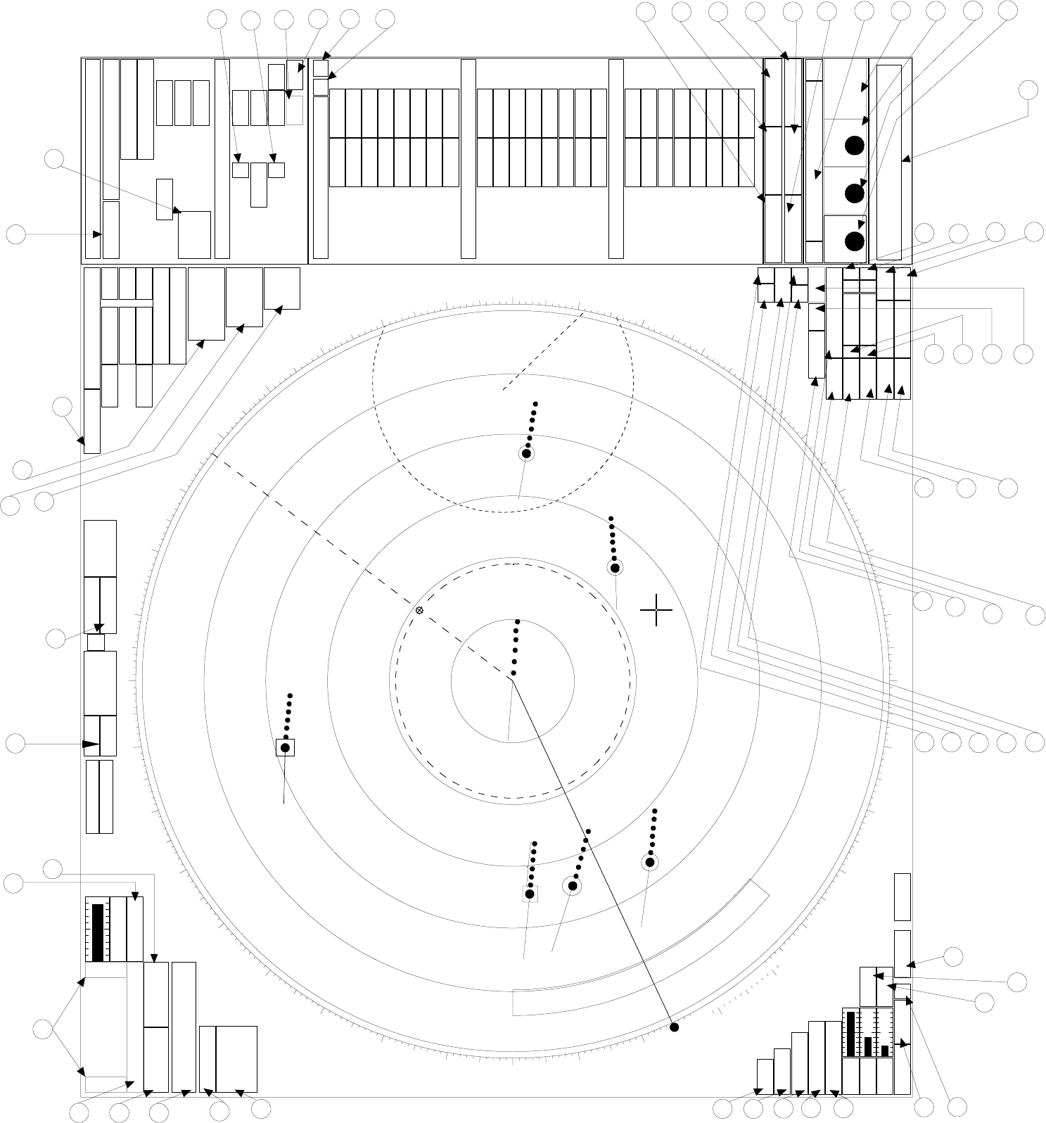
付図12 Fig.12
レーダー画面
RADAR Display

Main Menu - 1IR →
2 Process →
3 Target Enhance →
4 Zoom →
5 SART →
6 NAV Information - 1 Waypoint Display →
→
Section 3.8 page 3-74
2 NAV Display Setting - 1 NAV Line
→
Section 3.8.2 page 3-75
2 Coast Line
3 Contour
4 Mark1
5 Mark2
6 Mark3
7 Mark4
-3 User Map Setting - 1 Own Ship Position →
→
Section 3.8.4 page 3-82
2 Load →
Section 3.8.4 page 3-
- 1 Device
2 Load User Map
3 Unload →
Section 3.8.4 page
4 Save →
Section 3.8.4 page 3-
- 1 Device
2 Save User Map
3 All Files to Card2
5 Erase →
Section 3.8.4 page 3-
- 1 Device
2 Erase User Map
6 Edit User Map - 1 Clear Map Object - 1 NAV Line
→
Section 3.8.3 page 3-76
→
Section 3.8.3 page
2 Coast Line
3 Contour
4 Mark1
5 Mark2
6 Mark3
7 Mark4
8 All
2 Make Map Object - 1 NAV Line
→
Section 3.8.3 page
2 Coast Line
3 Contour
4 Mark1
5 Mark2
6 Mark3
7 Mark4
8 Enter
3 Correct →
4 Delete →
5 Insert →
7 Shift →
8 Shift Clear →
4Geodetic →
7
8 Graphic Display →
9 RADAR Menu(→Plot)
0 EXIT
RADAR Menu -1 Process Setting - 1 Video Latitude →
→
Section 3.10.1 page 3-
2 Video Noise Rejection →
3 Auto DR Control →
4 Process Switch →
5 2nd Process Mode →
6 Process Switch Range →
7 Fast Target Detection →
8 User Function Setting - 1 Function1 Setting -1 Mode
→
Section 3.11 page 3-120
2IR
3 Process
4 Target Enhance
5 Auto STC/FTC
7 Save Present State
8
9 NEXT
↓
1 Pulse Width 0.75nm
2 Pulse Width 1.5nm
3 Pulse Width 3/4nm
4 Pulse Width 6/8nm
5 Pulse Width 12nm
6 Pulse Width 16nm
9 NEXT
↓
1 Video Latitude
2 Video Noise Rejection
3 Auto DR Control
4 Process Switch
5 2nd Process Mode
6 Process Switch Range
7 Fast Target Detection
9 NEXT
↓
1 Trails Interval
2 Trails Mode
3 Trails REF Level
4 Trails Reduction
5 Time/CONT Combine
6 Trails Process
7 MAX Interval
9 NEXT
↓
1 Gain Offset
2 XMIT Repetition FREQ
3 Small Bouy Detect
4 Fishnet Detection
5 Antenna Height
8 Set Mode Default
9 Initialize
2 Function2 Setting
3 Function3 Setting
4 Function4 Setting
付図13
レ
ー
ダ
ー
メ
ニュー
階層
Fig.13 Over View of RADAR Menu
Section 3.8.3 page 3-79
Section 3.8.3 page 3-80
Section 3.8.3 page 3-81
Section 3.4.8 page 3-21
Section 3.5.12 page 3-49
Section 3.5.11 page 3-48
Section 6.5 page 6-9
Section 3.8.1 page 3-74
Section 3.5.13 page 3-50
Sectin 3.4.11 page 3-23
Section 3.10.1 page 3-98
Section 3.10.1 page 3-99
Section 3.10.1 page 3-99
Section 3.10.1 page 3-99
Section 3.10.1 page 3-97
Section 3.10.1 page 3-98
Section 3.10.1 page 3-98
Section 3.8.4 page 3-83
Section 3.8.4 page 3-88
Section 3.8.4 page 3-88
Section 3.8.5 page 3-89

2 RADAR Trails Setting - 1 Trails Interval →
→
Section 3.10.2 page 3-
2 Trails Mode →
3 Trails REF Level →
4 Trails Reduction →
5 Time/CONT Combine →
6 Trails Process →
7 MAX Interval →
3 Marker Setting - 1 EBL1 Setting - 1 EBL1 Bearing →
→
Section 3.5.3 page 3-27
2 EBL1 Floating →
3 EBL1 Bearing Fix →
2 EBL2 Setting - 1 EBL2 Bearing →
→
Section 3.5.3 page 3-27
2 EBL2 Floating →
3 EBL2 Bearing Fix →
3 VRM1 Range Unit →
4 VRM2 Range Unit →
5Parallel Index Line - 1 Display →
→
Section 3.5.5 page 3-33
2 Range Link →
3 PI Bearing REF →
4 PI Floating →
5 PI Bearing Fix →
6 PI Individual - 1 Line 1
→
Section 3.5.5 page 3-40
2 Line 2
3 Line 3
4 Line 4
5 Line 5
6 Line 6
7 Line 7
6 Cursor Setting - 1 EBL/VRM Control Cursor →
→
Section 3.10.3 page 3-102
2 Cursor Length →
7 EBL Maneuver Setting - 1 EBL Maneuver
→3.5.16章 page 3-55P 2 Reach
3 Turn Mode
4 Turn Set
4 Screen Setting - 1 Display Color Setting - 1 Day/Night →
→
Section 3.3.8 page 3-12
2 Color Scheme →
3 Outer PPI →
4 Inner PPI →
5 Character →
6 RADAR Echo →
7 RADAR Trails(Time) →
8 RADAR Trails(CONT) →
2 Brilliance Setting - 1 RADAR Video
→
Section 3.3.5 page 3-10
2 RADAR Trails
3 ATA/AIS
4 Fix Marker
5 EBL/VRM
6 Character
7 Panel
3 Numeric NAV INFO →
4 Depth Graph Setting - 1 Depth Graph Display →
2 Depth Range →
3 Time Range →
5 Wind/Current Graph →
6 DIR/DIST EXP Display →
5 TRX Setting - 1 PRF Fine Tuning →
2 Jamming →
4 XMIT Repetition FREQ →
6 Band Select →
6 Inter Switch Setting - 1 Change Pattern
→
Refer to the Operation
2 Load Pattern
Manual of Inter Switch
3 Save Pattern
In Appendix
4 Input IND. Name - 1 No.1
2 No.2
3 No.3
4 No.4
5 Input TRX Name - 1 No.1
2 No.2
3 No.3
4 No.4
Section 3.3.8 page 3-14
Section 3.3.8 page 3-14
Section 3.3.8 page 3-14
Section 3.3.8 page 3-14
Section 3.5.5 page 3-35
Section 3.5.5 page 3-36
Section 3.5.5 page 3-37
Section 3.5.5 page 3-38
Section 3.5.5 page 3-39
Section 3.10.4 page 3-106
Section 3.10.4 page 3-106
Section 3.3.8 page 3-12
Section 3.3.8 page 3-13
Section 3.3.8 page 3-14
Section 3.10.3 page 3-102
Section 3.10.3 page 3-102
Section 3.10.4 page 3-105
Section 3.10.4 page 3-104
Section 3.5.9 page 3-44
Section 3.10.2 page 3-100
Section 3.5.9 page 3-46
Section 3.5.4 page 3-32
Section 3.10.4 page 3-103
Section 3.5.3 page 3-27
Section 3.5.3 page 3-28
Section 3.5.3 page 3-27
Section 3.10.2 page 3-101
Section 3.10.2 page 3-101
Section 3.10.2 page 3-101
Section 3.10.2 page 3-100
Section 3.5.3 page 3-28
Section 3.5.3 page 3-29
Section 3.5.3 page 3-29
Section 3.5.4 page 3-31
Section 3.10.5 page 3-107
Section 3.10.5 page 3-108
Section 3.10.5 page 3-107
Section 3.10.4 page 3-104
Section 3.10.5 page 3-107
Section 3.3.8 page 3-14

7 NAV Equipment Setting - 1 Set GYRO →
3 Speed Equipment →
4 Manual Speed →
5 MAG Compass Setting - 1 Heading Correction →
→
Section 8.6 page 8-65
2 Correct Value →
6 Set/Drift Setting - 1 Correction →
→
Section 8.6 page 8-66
2 Set →
3 Drift →
7 GPS Setting -1
GPS Process Setting - 1 Position →
→
Section 8.6 page 8-68
2 Exclusion →
3 Geodetic →
4 Antenna Height →
5 Fix Mode →
6 DOP Level →
7 Position Average →
8 Master Reset →
9 Send Date
2DGPS Setting - 1 Mode →
→
Section 8.6 page 8-77
2 Frequency →
3 Baud Rate(BPS) →
4 DGPS Mode →
5 Send Data
3WAAS Setting - 1 Mode →
→
Section 8.6 page 8-81
2 Ranging →
3 NG WAAS →
4 WAAS Select Mode →
5 WAAS No. →
6 Send Data
4 GPS Status →
8 RADAR Sub Menu -1PIN Setting - 1 Load PIN Data →
→
Section 3.11.5 page 3-126
2 Save PIN Data →
3 Delete PIN Data →
2Multi Dial Setting 1 Vector Length →
→
Section 3.5.17 page 3-56
2 Trails Length →
3 ATA TGT Display No. →
4 C-UP Angle →
3User Key Setting - 1 User Key1
→
Section 3.5.18 page 3-58
2 User Key2
4 Date/Time Setting - 1 UTC/Local →
→
Section 8.6 page 8-89
2 Local Date →
3 Local Time →
4 Time Zone →
5 Buzzer Volume →
9Test Menu - 1 Self Test - 1 Memory Test →
→
Section 8.1 page 8-2
→
Section 8.1 page 8-3
2 Sensor Test →
3 Line Test →
2 Monitor Test - 1 Pattern 1 →
→
Section 8.1 page 8-7
2 Pattern 2 →
3 Pattern 3 →
4 Pattern 4 →
5 Pattern 5 →
6 Pattern 6 →
3 Panel Test - 1 Key Test →
→
Section 8.1 page 8-8
2 Buzzer Test →
3 Light →
4 PM Display →
5 Error Logging →
6 System INFO →
9Plot Menu
0EXIT
Section 3.9.1 page 3-91, Section 8.1 page 8-12
ection 3.5.17 page 3-56
ection 3.5.17 page 3-56
Section 8.1 page 8-7
Section 8.6 page 8-89
Section 8.1 page 8-4
Section 8.1 page 8-5
Section 8.1 page 8-6
Section 3.11.5 page 3-127
Section 3.11.5 page 3-128
ection 3.5.17 page 3-56
ection 3.5.17 page 3-56
Section 8.6 page 8-84
Section 8.6 page 8-85
Section 8.6 page 8-86
Section 3.11.5 page 3-126
Section 8.6 page 8-80
Section 8.6 page 8-81
Section 8.6 page 8-82
Section 8.6 page 8-83
Section 8.6 page 8-76
Section 8.6 page 8-77
Section 8.6 page 8-78
Section 8.6 page 8-79
Section 8.6 page 8-72
Section 8.6 page 8-73
Section 8.6 page 8-74
Section 8.6 page 8-75
Section 8.6 page 8-66
Section 8.6 page 8-68
Section 8.6 page 8-69
Section 8.6 page 8-70
Section 8.6 page 8-66
Section 8.6 page 8-65
Section 8.6 page 8-66
Section 8.6 page 8-65
Section 8.6 page 8-90
Section 8.6 page 8-90
Section 8.1 page 8-17
Section 8.6 page 8-89
Section 3.3.6 page 3-11
Section 8.6 page 8-62
Section 8.6 page 8-63
Section 8.6 page 8-64
Section 8.1 page 8-9
Section 8.1 page 8-7
Section 8.1 page 8-7
Section 8.1 page 8-7
Section 8.1 page 8-7
Section 8.1 page 8-7
Section 8.1 page 8-10
Section 8.1 page 8-11
Section 8.1 page 8-13

Plot Menu -1 Own Track Setting - 1 Own Track Internval →
2 Display Own Track →
3 Clear Own Track →
4 Own Track Memory →
5 Map Setting 1 Fill Land Area →
2 C-MAP Setting - 1 Grid Display →
→
Section 3.10.6 page 3-113
2 Sounding Display →
3 Soundings Unit →
4 Light Sectors Display →
5 Light Sectors Level →
3 JRC/ERC Card Setting - 1 Day/Night →
→
Section 3.10.6 page 3-109
2 Color of Land →
3 BRT of Land →
4 Color of Sea →
5 BRT of Sea →
6 Color of Name →
7 BRT of Name →
9 NEXT
↓
1 LAT/LON Line →
2 Color of L/L Line →
3 BRT of L/L Line →
4 ERC Display Request →
5 ERC Mark →
6 JRC Card Display - 1 Lighthouse →
2 Bouy →
3 Rough Line →
4 Other Line →
4 Contour Setting - 1 10m
→
Section 3.10.6 page 3-112
2 20m
3 30m
4 40m
5 50m
6 60m
7 70m
8 80m
9 Other
5 Map Display Setting - 1 Shift Coast Line 1 →
→
Section 3.10.6 page 3-115
2 Shift Coast Line 2 →
3 LAT/LON Correction →
4 Map Center Position →
5 Loran C Correction - 1 Chain
→
Section 3.10.6 page 3-119
2 TD1
3 TD2
4 TD1 Correction
5 TD2 Correction
6 MEM CAPA/Copy - 1 Copy Internal -> Card2 →
→
Section 3.12.1 page 3-
2 Copy Card2 -> Internal →
3 Copy Card1->Card2 →
4 Clear File →
7 Show Card1 →
8 Show Card2 →
7 CLR MEM/INIT Card - 1 CLR Mark/Line Data →
→
Section 3.12.2 page 3-
3 Format Card2 →
0 EXIT
Section 3.10.6 page 3-109
Section 3.10.6 page 3-109
Section 3.12.1 page 3-132
Section 3.12.2 page 3-133
Section 3.12.2 page 3-133
Section 3.12.1 page 3-131
Section 3.10.6 page 3-110
Section 3.10.6 page 3-110
Section 3.10.6 page 3-110
Section 3.10.6 page 3-113
Section 3.10.6 page 3-114
Section 3.10.6 page 3-114
Section 3.10.6 page 3-114
Section 3.10.6 page 3-109
Section 3.10.6 page 3-110
Section 3.12.1 page 3-131
Section 3.6.3 page 3-69
Section 3.6.4 page 3-70
Section 3.6.1 page 3-67
Section 3.6.2 page 3-68
Section 3.7.3 page 3-73
Section 3.10.6 page 3-111
Section 3.10.6 page 3-110
Section 3.10.6 page 3-110
Section 3.10.6 page 3-111
Section 3.10.6 page 3-111
Section 3.10.6 page 3-111
Section 3.10.6 page 3-111
Section 3.10.6 page 3-113
Section 3.10.6 page 3-111
Section 3.10.6 page 3-111
Section 3.10.6 page 3-115
Section 3.10.6 page 3-116
Section 3.10.6 page 3-117
Section 3.10.6 page 3-118
Section 3.12.1 page 3-132
Section 3.12.1 page 3-132
Section 3.12.1 page 3-131

ATA Menu - 1 ATA Setting - 1 Vector Time →
2 Past Position →
3 CPA Limit →
4 TCPA Limit →
5 CPA Ring →
6 Trial - 1 Trial
→
Section 5.3.7 page 5-37
2 Course
3 Speed
9 Target Number Display →
1 EPA Setting - 1 Vector Time →
(ATAなし時) 2 Plot Number →
3 CPA Limit →
4 TCPA Limit →
5 CPA Ring →
6 Audible Warning →
2 AIS Setting - 1 AIS Function →
2 AIS Symbol Display →
3 ATA Symbol Display →
4 CPA Limit →
5 TCPA Limit →
6 AIS Filter Setting - 1 Filter Type →
2 Make AIS Filter →
3 Filter Display →
4 ENT
7 Identical Distance →
3 ATA Track Setting - 1 Track Function →
2 Track Color - 1 All
→
Section 5.3.9 page 5-45
2 ATA Track No.1
3 ATA Track No.2
4 ATA Track No.3
5 ATA Track No.4
6 ATA Track No.5
7 ATA Track No.6
8 ATA Track No.7
9 NEXT
↓
1 ATA Track No.8
2 ATA Track No.9
3 ATA Track No.10
4 Other
3 Track Display - 1 All
→
Section 5.3.9 page 5-46
2 ATA Track No.1
3 ATA Track No.2
4 ATA Track No.3
5 ATA Track No.4
6 ATA Track No.5
7 ATA Track No.6
8 ATA Track No.7
9 NEXT
↓
1 ATA Track No.8
2 ATA Track No.9
3 ATA Track No.10
4 Other
4 Track Memory Interval →
5 Clear Track Color →
6 Clear Track Number →
7 CARD2 Track Display →
4 Guard Zone Setting - 1 ATA Guard Zone - 1 Guard Zone 1 →
2 Guard Zone 2 →
3 Make Guard Zone 1 →
4 Make Guard Zone 2 →
5 ENT
2 RADAR Alarm - 1 Sector RADAR Alarm - 1 Sector Alarm1
→
Section 3.5.20 page 3-63
→
Section 3.5.20 page 3-66
2 Sector Alarm2
3 Make Sector Alarm - 1 Sector Alarm1
→
Section 3.5.20 page 3-65
2 Sector Alarm2
3 ENT
5 RADAR Alarm Mode →
6 Sensitivity Level →
3 Set GZ Alarm Key - 1 Guard Zone - 1 Guard Zone 1
→
Section 5.1.6 page 5-12
2 Guard Zone 2
2 Sector RADAR Alarm - 1 Sector Alarm1
→
Section 5.1.6 page 5-12
2 Sector Alarm2
5 Test Menu - 1 Test Video →
→
Section 5.3.8 page 5-
2 ATA Simulator →
3 Status →
4 Gate Display →
Section 5.3.4 page 5-21
Section 5.3.8 page 5-39
Section 5.4.7 page 5-60
Section 5.1.5 page 5-11
Section 5.1.5 page 5-11
Section 5.3.3 page5-21
3.5.20章 page 3-65P
3.5.20章 page 3-66P
Section 3.5.19 page 3-60
Section 3.5.19 page 3-60
Section 3.5.19 page 3-60
Section 5.3.9 page 5-50
Section 5.3.9 page 5-47
Section 5.3.9 page 5-48
Section 5.3.9 page 5-49
Section 3.5.19 page 3-60
Section 5.1.3 page 5-9
Section 5.1.4 page 5-10
Section 5.3.9 page 5-44
Section 5.1.3 page 5-9
Section 5.1.3 page 5-9
Section 5.1.4 page 5-10
Section 5.2.4 page 5-15
Section 5.4.2 page 5-54
Section 5.4.5 page 5-57
Section 5.4.1 page 5-52
Section 5.4.1 page 5-52
Section 5.1.3 page 5-9
Section 5.3.8 page 5-42
Section 5.4.8 page 5-61
Section 5.4.8 page 5-62
Section 5.4.8 page 5-63
Sectioon 5.4.9 page 5-64
Section 5.2.5 page 5-17
Section 5.3.8 page 5-40
Section 5.3.8 page 5-43

Adjust Menu -1 Equipment Setup - 1 Bearing Adjustment →
2 Range Adjustment →
3 Tune Adjustment →
4 TRX Setting - 1 Antenna Height →
2 Tune Peak Adjust
3 Tune Indicator Adjust
4 PM Adjustment →
5 MBS Level
6 MBS Area
7 Output Pulse →
8 Antenna Location →
5 COM Port Setting - 1 Baud Rate -1 COM1(GPS)
→
Section 8.5 pge 8-39
→
Section 8.5 pge 8-39
2 COM2(PC)
3 COM3(NAV1)
4 COM4(NAV2)
5 COM5(COMPASS)
2 RX Sentence -1 GPS(LL/COG/SOG)
→
Section 8.5 page 8-40
2 GPS(WPT/Time)
3 Depth
3 TX Port -1 TTM(ATA Target)
→
Section 8.5 page 8-41
2 TLL(ATA Target)
3 OSD
4 RSD
5 ALR
6 AIS
7 TTM(AIS Target)
8 TLL(AIS Target)
4 RX Port -1 GPS
→
Section 8.5 page 8-42
2 DLOG
3 Depth
4 Temperture
5 Wind
6 Current
6 NAV Setting - 1 SEL NAV Equipment →
→
Section 8.5 page 8-43
2 GPS ANT Location →
7 Sector Blank - 1 Sector1 →
→
Section 8.5 page 8-46
2 Sector2 →
3 Sector3 →
4 Make Sector1 →
5 Make Sector2 →
6 Make Sector3 →
9 Language →
2 Maintenance Menu 1 Safety Switch →
→
Section 8.5 page 8-49
2 Partial Master Reset →
3 ALL Master Reset →
4 Internal To Card2 →
5 Card2 To Internal →
9 SP/ATA INIT Setup - 1 Noise Level - 1 Main →
→
Section 8.5 page 8-54
3 Setting Mode →
2 ATA - 1 Vector Constant →
→
Section 8.5 page 8-56
2 Video TD Level →
3 Video High Level
4 Video Low Level
5 Gate Size
6 Limit Ring
3 MBS - 1 MBS Level →
2 MBS Area →
Section 8.5 page 8-59
Section 8.5 page 8-53
Section 8.5 page 8-54
Section 8.5 page 8-55
Section 8.5 page 8-49
Section 8.5 page 8-50
Section 8.5 page 8-51
Section 8.5 page 8-58
Section 8.5 page 8-52
Section 8.5 page 8-36
Section 8.5 page 8-46
Section 8.5 page 8-46
Section 8.5 page 8-47
Section 8.5 page 8-43
Section 8.5 page 8-44
Section 8.5 page 8-37
Section 8.5 page 8-47
Section 8.5 page 8-48
Section 8.5 page 8-46
Section 8.5 page 8-56
Section 8.5 page 8-57
Section 8.6 page 8-91
Section 8.5 page 8-32
Section 8.5 page 8-33
Section 8.5 page 8-34
Section 8.5 page 8-35
Section 8.5 page 8-47

For further information contact:
Since1915
HEAD OFFICE & Nittochi Nishi-shinjuku bldg,
SALES DEPT. 10-1,Nishi-Shinjuku 6-chome,Shinjuku-ku,
Tokyo 160-8328 JAPAN
Phone :+81-3-3348-0151
Fax :+81-3-3348-3648
MAIN PLANT 1-1,Shimorenjaku 5-chome,Mitaka-shi,
Tokyo 181-8510 JAPAN
Phone :+81-422-45-9111
Fax :+81-422-45-9110
FIRS T EDITION
AUG. 2004
CODE No.7ZPRD0597 JRC