Japan Radio NKE2252 25KW X-Band Radar Transceiver User Manual
Japan Radio Co Ltd. 25KW X-Band Radar Transceiver
UserManual.wiki
>
Japan Radio
>
NKE2252 User Manual
>
Instruction manual 3 of 3
Contents
1.
Instruction manual 1 of 3
2.
Instruction manual 2 of 3
3.
Instruction manual 3 of 3
Instruction manual 3 of 3
Navigation menu
Upload a User Manual
Namespaces
Wiki Guide
HTML
PDF
Info
Views
User Manual
Discussion / Help
Navigation
![11─4 11 11.4 SCANNER (NKE-2102) (1) Dimensions Height 440mm´Swing Circle 1910mm (2) Mass Approx. 31kg (3) Polarization Horizontal Polarization (4) Directional Characteristic Horizontal Beam Width: 1.2° (-3dB width) Vertical Beam Width: 20° (-3dB width) Sidelobe Level: Below –26dB (within ±10°) Below –30dB (outside ±10°) (5) Revolution Approx. 27rpm (Normal) (6) Peak Power 10kW (7) Transmitting Frequency 9410 ±30MHz (8) Transmitting Tube Magnetron [MSF1425B] (9) Pulse width/Repetition Frequency Short Middle Long 0.125nm 0.08mS/2250Hz 0.25nm 0.08mS/2250Hz 0.5nm 0.08mS/2250Hz 0.75nm 0.08mS/2250Hz 0.25mS/1700Hz 1.5nm 0.08mS/2250Hz 0.25mS/1700Hz 0.5mS/1200Hz 3nm 0.25mS/1700Hz 0.5mS/1200Hz 0.8mS/750Hz 6nm 0.5mS/1200Hz 0.8mS/750Hz 1.0mS/650Hz 12nm 0.5mS/1200Hz 0.8mS/750Hz 1.0mS/650Hz 24nm 1.0mS/650Hz 48nm 1.0mS/650Hz 96nm 1.0mS/520Hz (10) Duplexer Circulator + Diode Limiter (11) Mixer MIC Front End (12) Intermediate Frequency Amplifier Intermediate Frequency: 60MHz Band Width: 20MHz(0.08mS) 6MHz(0.25mS) 3MHz(0.5mS, 0.8mS, 1mS) Gain: More than 90dB Amplifying Characteristics: Logarithmic Amplifier (13) Overall Noise Figure 6dB(Average)](https://usermanual.wiki/Japan-Radio/NKE2252.Instruction-manual-3-of-3/User-Guide-482880-Page-13.png)
![11─5 11.5 SCANNER (NKE-2252-7/9) (1) Dimensions 25kW-7ft: Height 440mm´Swing Circle 2270mm 25kW-9ft: Height 440mm´Swing Circle 2825mm (2) Mass 25kW-7ft: Approx. 54 kg 25kW-9ft: Approx. 56 kg (3) Polarization Horizontal Polarization (4) Directional Characteristics Horizontal Beam Width: 1.0° (7ft, -3dB width) 0.8° (9ft, -3dB width) Vertical Beam Width 20° (7/9ft, -3dB width) Sidelobe Level: Below –26dB (7/9ft, within ±10°) Below –30dB (7/9ft, outside ±10°) (5) Revolution 24rpm (7/9ft, Normal) (6) Peak Power 25kW ±50% (7) Transmitting Frequency 9410 ±30MHz (8) Transmitting Tube Magnetron [M1568B(J)] (9) Pulse Width/Repetition Frequency Short Middle Long 0.125nm 0.07mS/2200Hz 0.25nm 0.07mS/2200Hz 0.5nm 0.07mS/2200Hz 0.75nm 0.07mS/2200Hz 0.2mS/2200Hz 1.5nm 0.07mS/2200Hz 0.2mS/2200Hz 0.4mS/1400Hz 3nm 0.2mS/2200Hz 0.4mS/1400Hz 0.8mS/750Hz 6nm 0.4mS/1400Hz 0.8mS/750Hz 1.0mS/650Hz 12nm 0.4mS/1400Hz 0.8mS/750Hz 1.0mS/650Hz 24nm 1.0mS/650Hz 48nm 1.0mS/650Hz 96nm 1.2mS/520Hz (10) Duplexer Circulator + Diode Limiter (11) Mixer MIC Front End (12) Intermediate Frequency Amplifier Intermediate Frequency: 60MHz Band Width: 20MHz(0.08mS) 6MHz(0.2mS, 0.4mS) 3MHz(0.8mS, 1mS, 1.2mS) Gain: More than 90dB Amplifying Characteristics: Logarithmic Amplifier (13) Overall Noise Figure 6dB(Average)](https://usermanual.wiki/Japan-Radio/NKE2252.Instruction-manual-3-of-3/User-Guide-482880-Page-14.png)
![11─6 11 11.6 SCANNER (NKE-1075A) (1) Dimensions Height 837mm´Swing Circle 3758mm (2) Mass Approx. 163kg (3) Polarization Horizontal Polarization (4) Directional Characteristics Horizontal Beam Width 12ft: 1.9° Vertical Beam Width 12ft: 30° Sidelobe Level: Below –26dB (within ±10°) Below –30dB (outside ±10°) (5) Revolution 24/21rpm (60/50Hz) (6) Peak Power 30kW ±50% (7) Transmitting Frequency 3050 ±30MHz (8) Transmitting Tube Magnetron [M1302]] (9) Pulse Width/Repetition Frequency Short Middle Long 0.125nm 0.07mS/1900Hz 0.25nm 0.0mS/1900Hz 0.5nm 0.0mS/1900Hz 0.75nm 0.07mS/1900Hz 0.2mS/1900Hz 1.5nm 0.07mS/1900Hz 0.2mS/1900Hz 0.3mS/1900Hz 3nm 0.2mS/1900Hz 0.3mS/1900Hz 0.6mS/1100Hz 6nm 0.3mS/1900Hz 0.6mS/1100Hz 1.2mS/570Hz 12nm 0.3mS/1900Hz 0.6mS/1100Hz 1.2mS/570Hz 24nm 1.2mS/570Hz 48nm 1.2mS/570Hz 96nm 1.2mS/570Hz (10) Duplexer Circulator + TRHPL (11) Mixer MIC Front End (12) Intermediate Frequency Amplifier Intermediate Frequency: 60MHz Band Width: 20MHz(0.07uS) 6MHz(0.2mS, 0.3mS) 3MHz(0.6mS, 1.2mS) Gain: More than 90dB Amplifying Characteristics: Logarithmic Amplifier (13) Overall Noise Figure 5dB(Average)](https://usermanual.wiki/Japan-Radio/NKE2252.Instruction-manual-3-of-3/User-Guide-482880-Page-15.png)
![11─7 11.7 SCANNER (NKE-2252-6HS) (1) Dimensions 25kW-6ft: Height 440mm´Swing Circle 1920mm (2) Mass Approx. 52 kg (3) Polarization Horizontal Polarization (4) Directional Characteristics Horizontal Beam Width: 1.2° Vertical Beam Width 20° (-3dB width) Sidelobe Level: Below –26dB (within ±10°) Below –30dB (outside ±10°) (5) Revolution 48rpm (Normal) (6) Peak Power 25kW ±50% (7) Transmitting Frequency 9410 ±30MHz (8) Transmitting Tube Magnetron [M1568B(J)] (9) Pulse Width/Repetition Frequency Short Middle Long 0.125nm 0.07mS/2200Hz 0.25nm 0.07mS/2200Hz 0.5nm 0.07mS/2200Hz 0.75nm 0.07mS/2200Hz 0.2mS/2200Hz 1.5nm 0.07mS/2200Hz 0.2mS/2200Hz 0.4mS/1400Hz 3nm 0.2mS/2200Hz 0.4mS/1400Hz 0.8mS/750Hz 6nm 0.4mS/1400Hz 0.8mS/750Hz 1.0mS/650Hz 12nm 0.4mS/1400Hz 0.8mS/750Hz 1.0mS/650Hz 24nm 1.0mS/650Hz 48nm 1.0mS/650Hz 96nm 1.2mS/520Hz (10) Duplexer Circulator + Diode Limiter (11) Mixer MIC Front End (12) Intermediate Frequency Amplifier Intermediate Frequency: 60MHz Band Width: 20MHz(0.08mS) 6MHz(0.2mS, 0.4mS) 3MHz(0.8mS, 1mS, 1.2mS) Gain: More than 90dB Amplifying Characteristics: Logarithmic Amplifier (13) Overall Noise Figure 6dB(Average)](https://usermanual.wiki/Japan-Radio/NKE2252.Instruction-manual-3-of-3/User-Guide-482880-Page-16.png)
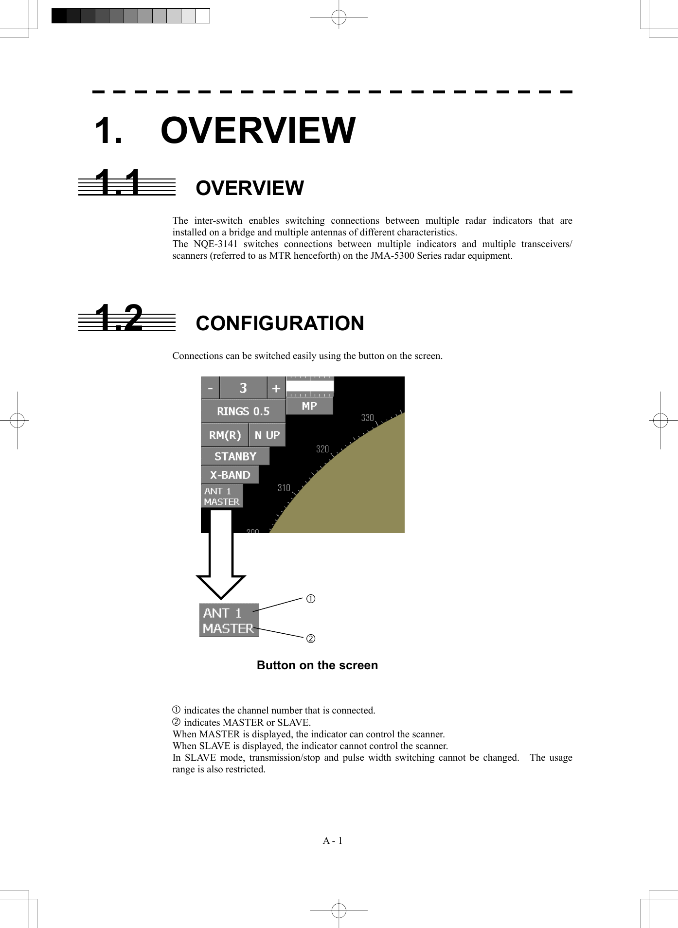
![A - 2 APPENDIX APPENDIX Click on . Change the indicator to which the scanner is connected and click on . Click on the switch on the top-left corner of the screen. When the switch on the top-left corner of the screen is set to , set it to by clicking on the left button. 2. OPERATION When switching an inter-switch pattern, set the inter-switch to STANDBY and operate the switches on the indicator panel according to the following flow. 2.1 OPERATION FLOW Flow from opening to the closing of the menu [Close the Inter Switch menu] [Set the inter-switch to a standby state] [Switch the inter-switch pattern] [Open the Inter Switch menu]](https://usermanual.wiki/Japan-Radio/NKE2252.Instruction-manual-3-of-3/User-Guide-482880-Page-33.png)
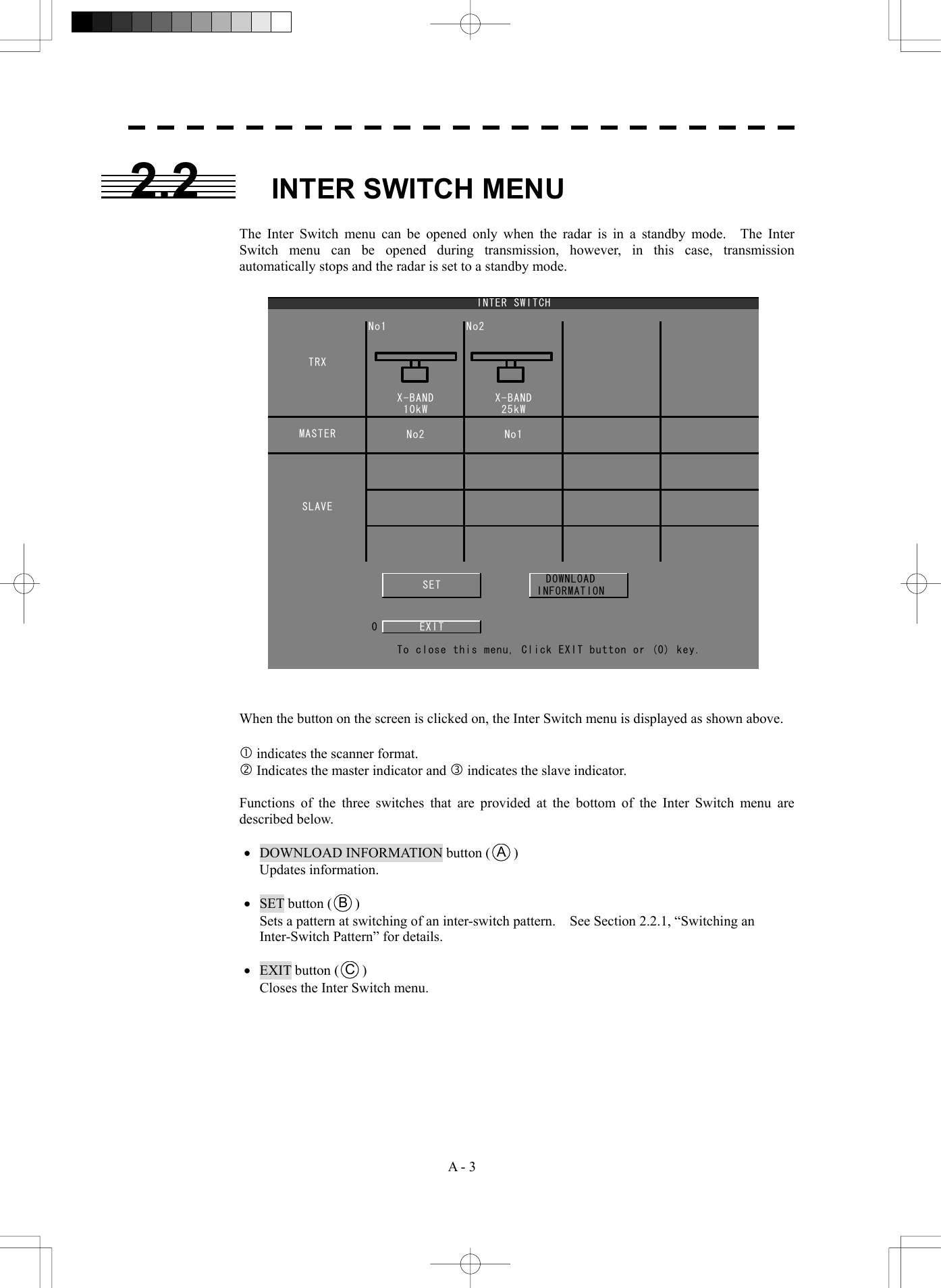
![A - 4 APPENDIX APPENDIX 2.2.1 Switching an Inter-Switch Pattern···················································· This section uses an example that controls two indicators and two scanners. [1] Switching two indicators (cross connection) Procedure 1. Press the [RADAR MENU] key twice. Press the [6] key. The Inter Switch Setting menu is opened. Press the [1] key. The Change Pattern screen is displayed. * Indicators can also be switched by using the 2-9P radar screen j button. Inter Switch Setting1. Change Pattern2. Load Pattern >3. Save Pattern >4. Input IND. Name >5. Input TRX Name >0. EXIT](https://usermanual.wiki/Japan-Radio/NKE2252.Instruction-manual-3-of-3/User-Guide-482880-Page-35.png)
![A - 5 X-BAND10kWX-BANDNo2MASTER No1 No2SLAVE25kWINTER SWITCHTRXNo1c d 2. Set the cursor to the panel of the indicator to be switched and press the [ENT] key. Select the panel in which the indicator name is displayed within the bold frame as shown above. Panels of the indicators that are not displayed cannot be selected. Example: Set the cursor to panel c and press the [ENT] key. The panel of the selected indicator is displayed in reverse video.](https://usermanual.wiki/Japan-Radio/NKE2252.Instruction-manual-3-of-3/User-Guide-482880-Page-36.png)
![A - 6 APPENDIX APPENDIX 3. Set the cursor to the panel of another indicator and press the [ENT] key. Example: Set the cursor to panel d and press the [ENT] key. Indicator d and indicator c are switched. The names of indicators c and d are switched as follows. 4. Click on SET at the bottom of the Inter Switch menu. The inter-switch pattern switching is set. 5. Click on EXIT at the bottom of the Inter Switch menu. The Inter Switch menu is closed. 25kWINTER SWITCHTRXNo1MASTER No2 No1SLAVENo2X-BAND10kWX-BANDc d](https://usermanual.wiki/Japan-Radio/NKE2252.Instruction-manual-3-of-3/User-Guide-482880-Page-37.png)
![A - 7 Inter Switch Setting1. Change Pattern2. Load Pattern >3. Save Pattern >4. Input IND. Name >5. Input TRX Name >0. EXIT [II] Setting one indicator as a slave of another indicator (slave connection) Procedure 1. Press the [RADAR MENU] key twice. Press the [6] key. The Inter Switch Setting menu is opened. Press the [1] key. The Change Pattern screen is displayed. * Indicators can also be switched by using the 2-9P radar screen j button.](https://usermanual.wiki/Japan-Radio/NKE2252.Instruction-manual-3-of-3/User-Guide-482880-Page-38.png)
![A - 8 APPENDIX APPENDIX X-BAND10kWX-BANDNo2MASTER No1 No2SLAVE25kWINTER SWITCHTRXNo1c d e 2. Set the cursor to the panel of the indicator to be set as a slave and press the [ENT] key. Select the panel in which the indicator name is displayed within the bold frame as shown above. Panels of the indicators that are not displayed cannot be selected. Example: Set the cursor to panel c and press the [ENT] key. The panel of the selected indicator is displayed in reverse video.](https://usermanual.wiki/Japan-Radio/NKE2252.Instruction-manual-3-of-3/User-Guide-482880-Page-39.png)
![A - 9 25kWINTER SWITCHTRXNo1MASTER No2SLAVENo1No2X-BAND10kWX-BANDc d e 3. Set the cursor to the panel under the indicator that is to be set as a master and press the [ENT] key. Example: Set the cursor to panel e and press the [ENT] key. Indicator c moves to position e. Indicator c is set to a slave of indicator d as shown below. 4. Click on SET at the bottom of the Inter Switch menu. The inter-switch pattern switching is set. 5. Click on EXIT at the bottom of the Inter Switch menu. The Inter Switch menu is closed.](https://usermanual.wiki/Japan-Radio/NKE2252.Instruction-manual-3-of-3/User-Guide-482880-Page-40.png)
![A - 10 APPENDIX APPENDIX 2.3 READING INTER-SWITCH PATTERNS Inter-switch patterns that have been saved can be read. Procedure 1. Press the [RADAR MENU] key twice. Press the [6] key. The Inter Switch Setting menu is opened. Press the [2] key. The Load Pattern screen is displayed. 2. Select the number of the file to which the pattern is to be loaded using any of the numeric keys [1] to [5]. The loaded inter-switch pattern is reflected. Load Pattern1. 2. 3. 4. 5. 0. EXIT 9. NEXT >](https://usermanual.wiki/Japan-Radio/NKE2252.Instruction-manual-3-of-3/User-Guide-482880-Page-41.png)
![A - 11 2.4 SAVING INTER-SWITCH PATTERNS Inter-switch patterns can be saved. Procedure 1. Press the [RADAR MENU] key twice. Press the [6] key. The Inter Switch Setting menu is opened. Press the [3] key. The Save Pattern screen is displayed. 2. Select the number of the file in which the pattern is to be saved using any of numeric keys [1] to [5]. An alphanumeric key screen is displayed. 3. Enter a name using alphanumeric keys and press the ENT button. The data is saved under the file name that was entered. 9. NEXT >Save Pattern1. 2. 3. 4. 5. 0. EXIT 1 2 34 5 6 7 8 90 B C DE F G H I JA L M N O P Q R S TK V W X Y Z SP < >U DEL ENT BS Save PatternEXIT](https://usermanual.wiki/Japan-Radio/NKE2252.Instruction-manual-3-of-3/User-Guide-482880-Page-42.png)
![A - 12 APPENDIX APPENDIX 2.5 NAMING INDICATORS Names can be assigned to indicators. Procedure 1. Press the [RADAR MENU] key twice. Press the [6] key. The Inter Switch Setting menu is opened. Press the [3] key. The Input IND. Name screen is displayed. 2. Select the number of the indicator to be named using any of numeric keys [1] to [4]. An alphanumeric key screen is displayed. 3. Enter a name using alphanumeric keys and press the ENT button. The name that was entered is reflected in the indicator. * Up to four indicators can be named. 1 2 34567890 B C DE F G H I JA L M N O P Q R S TK V W X Y Z SP < >U DEL ENT BS No.1EXITInput IND. Name1. No.1 2. No.2 3. No.3 4. No.4 0. EXIT IND.1IND.2IND.3IND.4](https://usermanual.wiki/Japan-Radio/NKE2252.Instruction-manual-3-of-3/User-Guide-482880-Page-43.png)
![A - 13 2.6 NAMING SCANNERS Names can be assigned to scanners. Procedure 1. Press the [RADAR MENU] key twice. Press the [6] key. The Inter Switch Setting menu is opened. Press the [4] key. The Input TRX Name screen is displayed. 2. Select the number of the scanner to be named using any of numeric keys [1] to [4]. An alphanumeric key screen is displayed. 3. Enter a name using alphanumeric keys and press the ENT button. The name that was entered is reflected in the scanner. * Up to four scanners can be named. 1 2 34 5 6 7 8 90 B C DE F G H I JA L M N O P Q R S TK V W X Y Z SP < >U DEL ENT BS No.1EXITInput TRX Name1. No.1 2. No.2 3. No.3 4. No.4 0. EXIT TRX1TRX2TRX3TRX4](https://usermanual.wiki/Japan-Radio/NKE2252.Instruction-manual-3-of-3/User-Guide-482880-Page-44.png)