Japan Radio NKE2252 25KW X-Band Radar Transceiver User Manual
Japan Radio Co Ltd. 25KW X-Band Radar Transceiver
UserManual.wiki
>
Japan Radio
>
NKE2252 User Manual
>
Instruction manual 2 of 3
Contents
1.
Instruction manual 1 of 3
2.
Instruction manual 2 of 3
3.
Instruction manual 3 of 3
Instruction manual 2 of 3
Navigation menu
Upload a User Manual
Namespaces
Wiki Guide
HTML
PDF
Info
Views
User Manual
Discussion / Help
Navigation
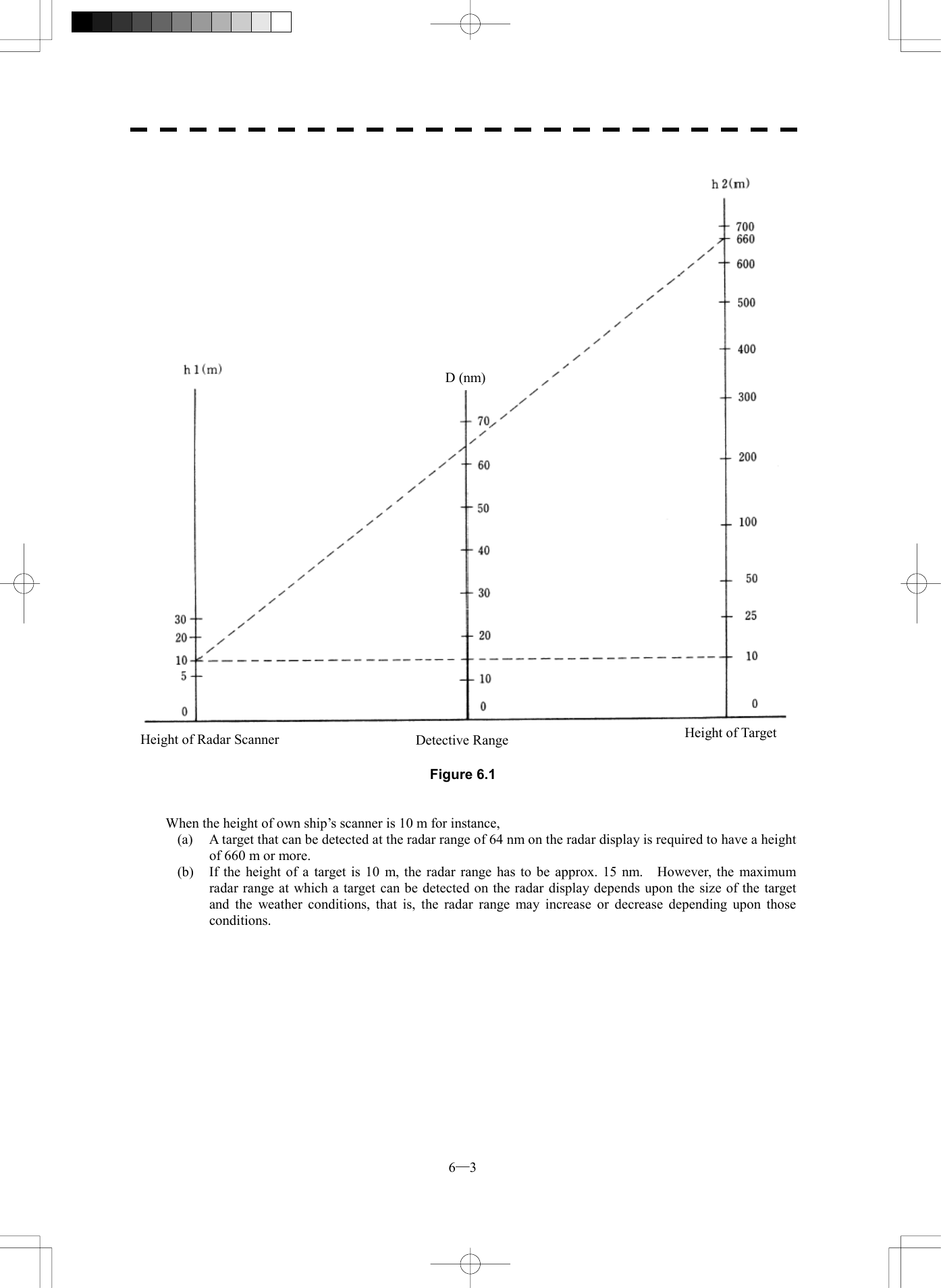
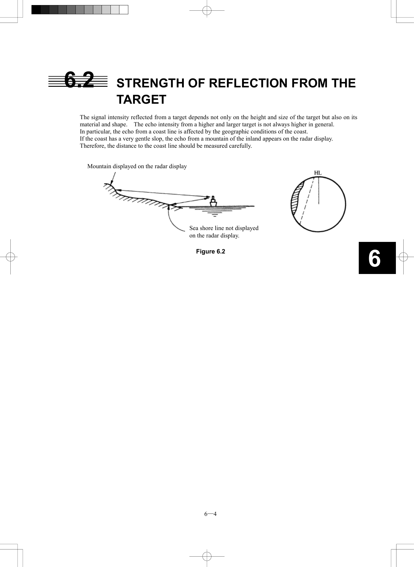
![4─2 4 4.2 MEASUREMENT BY RANGE RINGS Procedures 1 Press [RR/HL] key. The Range Rings will appear on the radar display. The range between the target and own ships can be determined by visually measuring the target’s position that lies between two range rings. (The range ring interval is fixed and indicated within the radar display on page 2-9.)](https://usermanual.wiki/Japan-Radio/NKE2252.Instruction-manual-2-of-3/User-Guide-482879-Page-3.png)
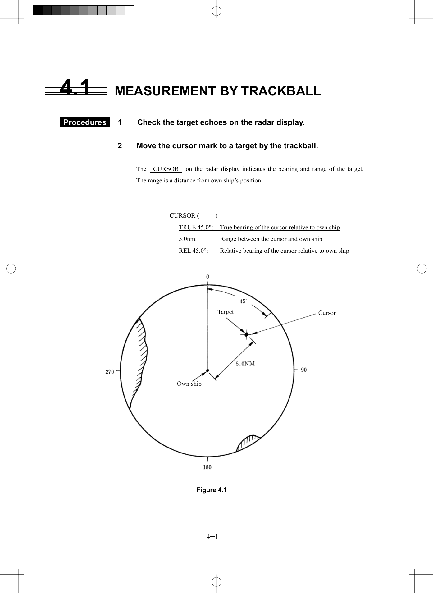
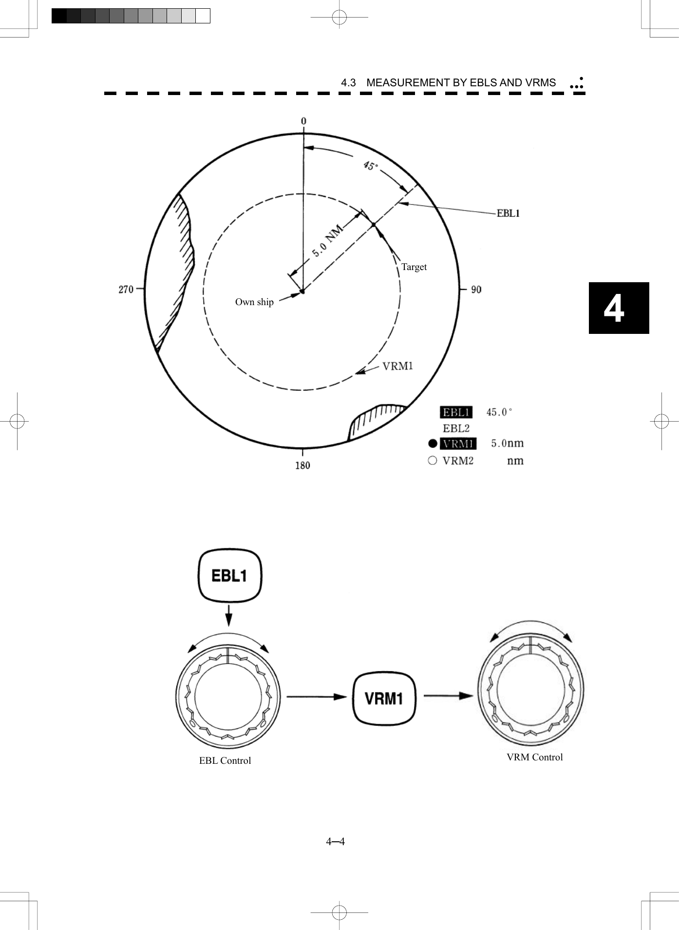
![4─3 4.3 MEASUREMENT BY EBLS AND VRMS ・・ Procedures 1 Press [EBL1] key to select EBL1 display and operation. The EBL1 indication at the lower right of the radar display will be selected and the EBL1 will appear as a broken-line on the PPI display. 2 Turn the [EBL] control to put EBL1 on a target. The bearing of the EBL1 will appear at the lower right of the radar display. The EBL1 bearing represents the target’s bearing. 3 Press [VRM1] key to select VRM1 display and operation. The VRM1 indication at the lower right of the radar display will be selected and the VRM1 will appear as a broken-line circle on the PPI display. 4 Move the broken-line VRM1 to the target by using the [VRM] control. The range of the VRM1 from own ship will appear at the lower right of the radar display. The range of VRM1 signifies a distance between the target and own ship. Refer to Figure 4.2 in the next page. In this Figure 4.2, the range and bearing are; Range: 5.0nm Bearing: 45.0°](https://usermanual.wiki/Japan-Radio/NKE2252.Instruction-manual-2-of-3/User-Guide-482879-Page-4.png)
![4─5 123.4EBL1 T °C004.3EBL2 T °C4.4 MEASUREMENT BETWEEN TWO OPTIONAL POINTS Procedures 1 Press [EBL2] key to select EBL2 display and operation. The EBL2 indication at the lower right of the radar display will be selected and the EBL2 will appear as a dotted-line on the PPI display. 2 Point the cursor to the C switch of EBL2 at the lower right of the radar display, and press [ENT] key. The EBL cursor mode changes each time O or L is pressed. 3 Using the trackball, move the starting point of EBL2 to one (A) of the two points and press [ENT] key. (See Figure 4.3.) 4 Turn the [EBL] control to move EBL2 to the other point (B). (See Figure 4.3.) 5 Press [VRM2] key to select VRM2 display and operation. ¡ (VRM marker) will appear on a dotted-line of the EBL2. 6 Using the [VRM] control, move the VRM2 marker on a dotted-line of EBL2 to the point B. The bearing and range between the two points will appear in the VRM2 and EBL2 area on the lower right of the radar display.](https://usermanual.wiki/Japan-Radio/NKE2252.Instruction-manual-2-of-3/User-Guide-482879-Page-6.png)
![4─6 4 4.4 MEASUREMENT BETWEEN TWO OPTIONAL POINTS RINGS Figure 4.3 It is also possible to use EBL1 instead of EBL2 in measuring the bearing and range between two optional points. In this case, read EBL2 as EBL1 and VRM2 as VRM1 in the procedure above, point the cursor to C of EBL2 in step 2, and then press [ENT] key. EBL Control Starting point of EBL2CapeBVRM2 MarkerOwn shipAVRM Control](https://usermanual.wiki/Japan-Radio/NKE2252.Instruction-manual-2-of-3/User-Guide-482879-Page-7.png)

![5─1 USAGE OF ARPA l There are the following limitations on use of the target acquisition and tracking functions of ARPA. [I] Resolution between adjacent targets and swapping during automatic tracking Depending on the particular distance and echo size, resolution between adjacent targets during automatic tracking usually ranges somewhere between 0.03 to 0.05 nm. If multiple targets approach each other, resolution will become about 0.03 nm and this may cause the system to regard them as one target and thus to swap them or lose part of them. Such swapping or less of targets may also occur if the picture of the target being tracked is affected by rain/snow clutter returns or sea clutter returns or moves very close to land. [II] Intensity of echoes and the tracking function The intensity of echoes and the tracking function have a correlationship,and thus the target will be lost if no echoes are detected during six scans in succession. If a lost target exists, therefore, radar gain must be increased to support detection of the target. If, however, radar gain is increased too significantly, sea clutter returns or other noise may be erroneously detected and tracked as a target, and resultingly, a false alarm may be issued. [III] Adverse effects of error sources on automatic tracking To execute accurate tracking, it becomes necessary first to appropriatelyadjust the [GAIN], [SEA] and [RAIN] controls of the radar so that the target to be acquired and tracked id clearly displayed on the radar display. Inappropriate settings of these controls reduce the reliability/accuracy of automatic tracking. Attention](https://usermanual.wiki/Japan-Radio/NKE2252.Instruction-manual-2-of-3/User-Guide-482879-Page-10.png)
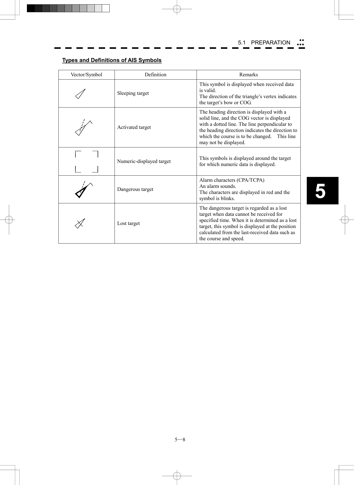
![5─7 5.1.2 Definitions of Symbols Types and Definitions of EPA, ATA, and ARPA Symbols Vector/Symbol Definition Remarks Safe target Dangerous target Alarm characters (CPA/TCPA) appear and an alarm sounds. The vector and symbol blinks with red lamp. Target for which numeric data is displayed When numeric data is displayed, the target symbol is changed into □. Initial acquisition mark (EPA) This symbol is displayed when the first plotting is performed. (ATA/ARPA) This symbol is displayed until the vector is displayed after target acquisition. Target that has intruded into the guard zone Alarm characters (GZ) appear and an alarm sounds. The characters blinks with red lamp. Lost target (a target that can not be tracked for any reason) Alarm characters (LOST) appear and an alarm sounds. The symbol blinks. No vector is displayed. Trackball cross cursor mark This mark is used to designate a target when acquiring manually and canceling it and indicating its numerical data. A target’s past positions The symbol and vector is displayed only when [PAST POSN] is ON. The position interval can be set to OFF/0.5min/1min/2min/4min 0.1nm/0.2nm/0.5nm/1nm M Plot data modification This symbol is displayed only for (EPA). “M” is shown beside the symbol indicating that plotted target data is being modified. The previous plotting position is displayed. U Plot data update request This symbol is displayed only for (EPA). This symbol is displayed when plotted target data is not updated for 10 minutes. When it is not updated, the symbol disappears after 5 minutes. A LOST alarm sounds.](https://usermanual.wiki/Japan-Radio/NKE2252.Instruction-manual-2-of-3/User-Guide-482879-Page-16.png)
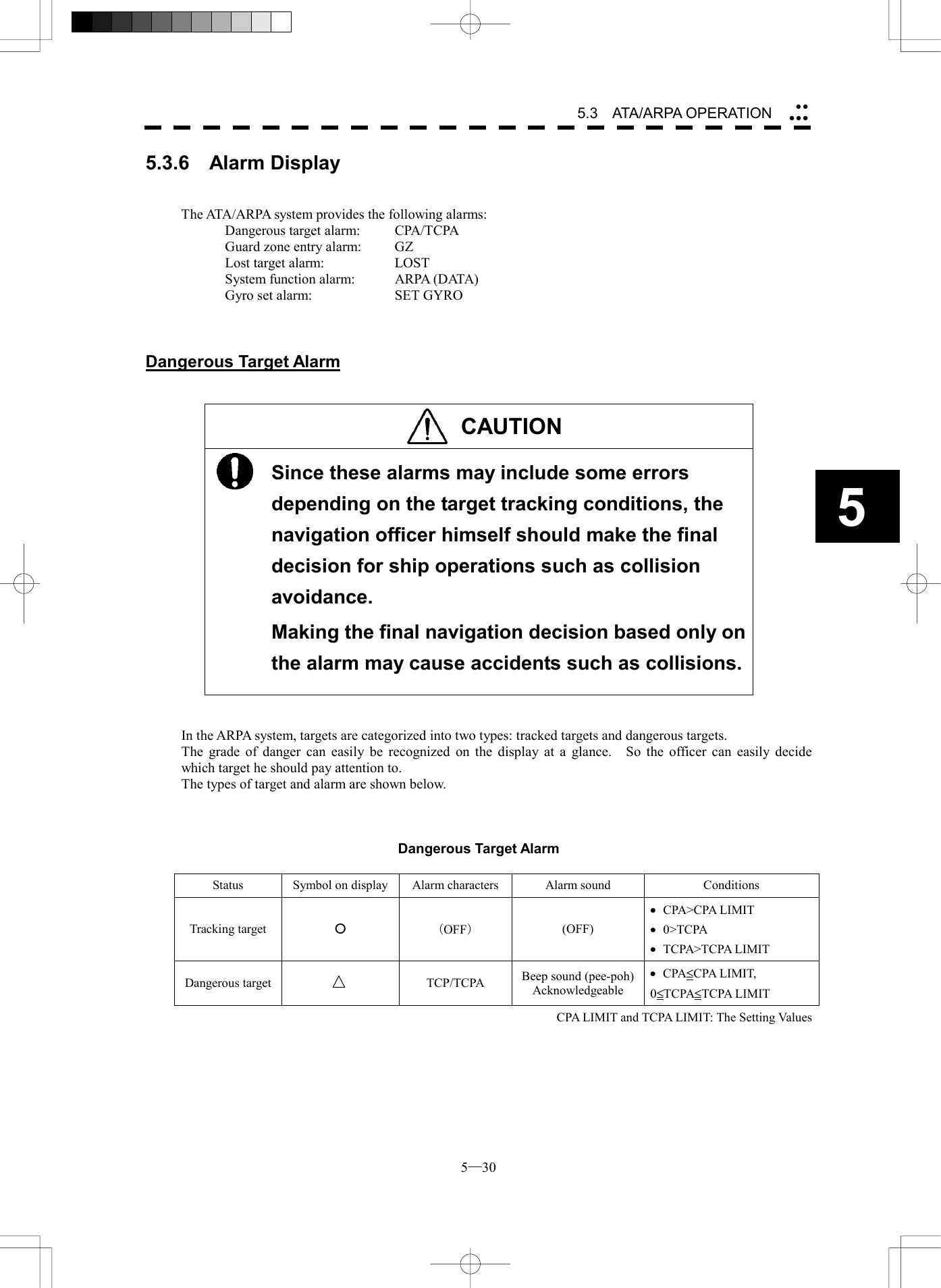
![5─9 ATA Setting1. Vector Time6 min2. Past PositionOFF3. CPA Limit10 nm4. TCPA Limit1 min5. CPA RingON6. Trial > 9. Target Number Display0. EXIT ON5.1.3 Setting Collision Decision Criteria (CPA/TCPA Limit) For details on each operation, see 3.4 BASIC OPERATION and 4 MEASUREMENT OF RANGE AND BEARING. Set and check collision decision criteria before operating the ARPA system. Procedures 1 Press [ATA MENU] key. 2 Press [1]. The ATA Setting menu will appear. 3 Press [3]. The ten-key screen will appear. 4 Select the value to be set pressing the numeric key, and press [ENT]. The selected CPA Limit value will be determined. 5 Press [4]. The ten-key screen will appear. 6. Select the value to be set pressing the numeric key, and press [ENT]. The selected TCPA Limit value will be determined. l Set the optimum values of collision decision conditions, depending upon vessel type, water area, weather and oceanographic conditions. (For the relations between those conditions and alarms, refer to section 5.3.6 Alarm Display. ) Attention](https://usermanual.wiki/Japan-Radio/NKE2252.Instruction-manual-2-of-3/User-Guide-482879-Page-18.png)
![5─10 55.1 PREPARATION ATA Setting1. Vector Time6min2. Past PositionOFF3. CPA Limit10 nm4. TCPA Limit1 min5. CPA RingON6. Trial > 9. Target Number Display0. EXITON5.1.4 Setting Vectors (Vector Time) Vector time can be set in minutes in the range 1 to 60 min. A true (T) vector mode or relative (R) vector mode can be selected. Setting vector time using the menu Procedures 1 Press [ATA MENU] key. 2 Press [1]. The ATA Setting menu will appear. 3 Press [1]. The ten-key screen will appear. 4 Select the vector time to be set pressing the numeric key, and press [ENT]. The selected vector time will be determined. Setting vector time using the multi-function control Procedures 1 Press the [MULTI] control several times to activate the VECTOR mode. VECTOR will appear in the MULTI mode field at the lower left of the radar display. 2 Turn the [MULTI] control to set the vector time. Setting vector mode Procedures 1 Press the [VECT] key to select the vector mode. T or R will appear indicating the vector mode in the ARPA information display area at the upper right of the radar display.](https://usermanual.wiki/Japan-Radio/NKE2252.Instruction-manual-2-of-3/User-Guide-482879-Page-19.png)
![5─11 ATA Setting1. Vector Time6 min2. Past PositionOFF3. CPA Limit10 nm4. TCPA Limit1 min5. CPA RingON6. TRIAL > 9. Target Number Display0. EXIT ON5.1.5 Setting CPA Ring (CPA Ring) Procedures 1 Press [ATA MENU] key. 2 Press [1]. The ATA Setting menu will appear. 3 Press [5]. The setting of CPA Ring will change between ON and OFF. ON: Displays the CPA ring. OFF: Hides the CPA ring. While the CPA ring is displayed, CPA RING is shown at the upper right of the radar display. While the distance of the specified CPA Limit value is used as the radius, the CPA ring is displayed with a red circle of which center is the own ship’s position. Note: The CPA ring is not displayed when the true (T) vector mode is selected. * The CPA ring switch to Display or Hide within the radar display 21 on page 2-7.](https://usermanual.wiki/Japan-Radio/NKE2252.Instruction-manual-2-of-3/User-Guide-482879-Page-20.png)
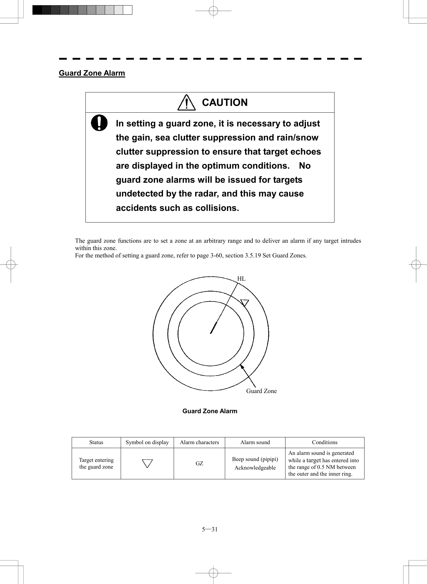
![5─12 55.1 PREPARATION Guard Zone Alarm Key Setting1. Guard Zone 1ON2. Guard Zone 2OFF 0. EXIT5.1.6 Setting Automatic Acquisition Key Assignment (GZ Alarm Key Setting) This section explains how to set a guard zone that is to be assigned to the [GZ ALARM] key. The setting enables the operator to select ON/OFF for a generally used guard zone by simply operating the [GZ ALARM] key on the control panel. Procedures 1 Press [ATA MENU] key. Press [4]. Press [3]. Press [1]. Guard Zone menu will appear. ON: Turns on the guard zone when the [GZ ALARM] key is pressed. OFF: Does not turn on the guard zone when the [GZ ALARM] key is pressed. The same function also as RADAR Alarm (Sector Alarm) can be given. Procedures 1 Press [ATA MENU] key. Press [4]. Press [3]. Press [2]. * The setting method is the same as the method of a guard zone. For the creation method of sector alarm, refer to 3-67P and Chapter 3.5.20 for the creation method of sector alarm. .](https://usermanual.wiki/Japan-Radio/NKE2252.Instruction-manual-2-of-3/User-Guide-482879-Page-21.png)
![5─13 5.2 EPA OPERATION This section explains how to use the EPA function. The EPA function is available when the ATA and ARPA options are not installed. The EPA function stores/displays vectors as the courses and speeds of target ships. The data of up to 10 target ships (plot/ID numbers 0-9) can be specified. The EPA function calculates CPA/TCPA, and issues an alarm. The data of plotted target ships is erased from memory when the power is turned off. The EPA function does not display any past plot data. * The same setting procedure for ATA/ARPA applies to the following settings. See the ATA/ARPA setting procedure. 1. Vector Time 2. Past Position 3. CPA Limit 4. TCPA Limit 5. CPA Ring 5.2.1 Plotting Targets Vectors are displayed when a target is plotted twice. A course and speed are calculated from the two plotting positions, and the plotted target moves in the course at the speed. The plot can be modified. The plot number (target ID number) is not displayed while Display ID Number is set to OFF. Procedures 1 Move the cross cursor mark onto the target on the radar display, and press the [ACQ] key to start the first plotting. 2 Enter the plot number (target ID number), pressing the numeric key(s) [0] to [9]. 3 Press [ENT] to finish the first plotting. The acquisition symbol and plot number will be displayed at the plotting position. 4 When 30 seconds to 15 minutes has passed after the first acquisition, move the cross cursor mark onto the current target position, and take steps 1 to 3 to perform the second plotting. When finishing the second plotting, the system clears the symbol and plot number that were displayed at the end of the first plotting, and displays the symbol (vector) and plot number at the second plotting position. The plotted target (symbol and plot/ID number) moves in a specified course at a specified speed. The course and speed are calculated from the two plotting positions. At this time, the CPA and TCPA at positions where the plotted target moves are calculated, and an alarm is issued when the plotted target goes into the guard zone.](https://usermanual.wiki/Japan-Radio/NKE2252.Instruction-manual-2-of-3/User-Guide-482879-Page-22.png)
![5─14 5.2 EPA OPERATION 55.2.2 Modifying Plotted Target Data The system modifies specified plotted target data. It clears the specified data, and displays the plotted target immediately before it moves to the clear position until re-acquiring a target. Procedures 1 Press the [ACQ] key. 2 Enter the plot number (target ID number) for modification, pressing the numeric key(s) [0] to [9]. 3 Press the [CLR] key. The previously updated status will be displayed. “M” is also displayed beside the mark, indicating that modification is in progress. 4 Move the cross cursor mark to the modification position to re-acquire a target. At this time, specify the plot number you entered in step 2. ([ACQ], [0]-[9], [ENT]) 5.2.3 Canceling Plotted Target Data The system cancels the display of specified plotted target data. Once plotted target data is canceled, it cannot be restored any more. Procedures 1 Press the [ACQ] key. 2 Enter the plot number for cancellation, pressing the numeric key(s) [0] to [9]. 3 Press the [TGT CNCL] key. The plotted target data of the specified plot number will be canceled. Canceling all plotted targets Procedures 1 Hold down the [TGT CNCL] key for 5 seconds or more. The plotted targets of all the plot numbers will be canceled.](https://usermanual.wiki/Japan-Radio/NKE2252.Instruction-manual-2-of-3/User-Guide-482879-Page-23.png)
![5─15 5.2.4 Displaying Numeric Data of Plotted Targets The following data is displayed for a specified plotted target: TGT ID Plot number BRG Bearing: 0.1° unit RANGE Range: 0.1 nm unit COURSE Target’s true course: 0.1° unit SPEED Target’s true speed: 0.1 knot unit CPA CPA: 0.1 nm unit TCPA TCPA: 0.1 min unit TIME Elapsed time: 0.1 min unit Procedures 1 Press the [TGT DATA] key. 2 Enter the plot number pressing the numeric keys [0] to [9]. 3 Press [ENT] key. The data of the specified plot number will be displayed. The mark of the target for which numeric data is displayed is changed into “□”.](https://usermanual.wiki/Japan-Radio/NKE2252.Instruction-manual-2-of-3/User-Guide-482879-Page-24.png)
![5─16 5.2 EPA OPERATION 5EPA Setting1. Vector Time6 min2. Past PositionOFF3. CPA Limit10 nm4. TCPA Limit1 min5. CPA RingON6. Audible Warning0. EXITON5.2.5 Setting EPA Alarm (Audible Warning) Alarm that may sound during the use of EPA can be set to ON/OFF. Procedures 1 Press [ATA MENU] key. Press [1] key. The EPA Setting menu will appear. 2 Press [6] key. EPA alarm sound is switched ON or OFF. ON: Sets the EPA alarm sound to ON. OFF: Sets the EPA alarm sound to OFF. Note: When this function turns off and CPA/TCPA alarm occurs, alarm does not sound. Take care for maneuvering the ship.](https://usermanual.wiki/Japan-Radio/NKE2252.Instruction-manual-2-of-3/User-Guide-482879-Page-25.png)
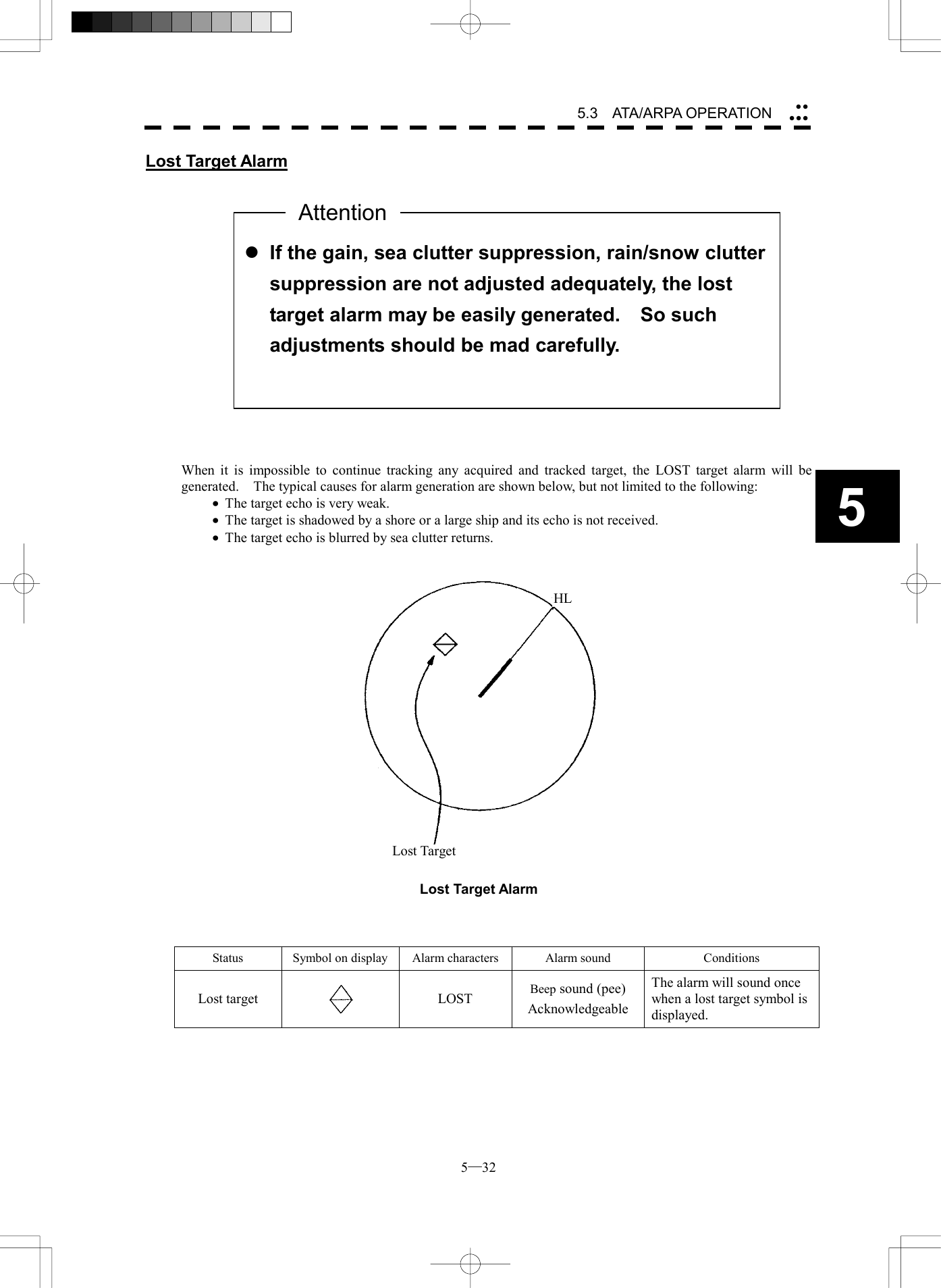
![5─17 l If untracked targets intrude into the guard zone in theconditions that maximum number of targets is under tracking, the targets acquired automatically will be cancelled in the order of lower levels of danger. 5.3 ATA/ARPA OPERATION This section explains how to use the ATA and ARPA functions. Each function is available only when the ATA or ARPA option is installed. The functions automatically track a target, and store/display vectors as the course and speed. They calculate CPA and TCPA, and issue an alarm. The basic operations of ATA and ARPA are the same, but available functions are different. The ATA function can track up to 30 ships; the ARPA function can track up to 100 ships. Both functions set a guard zone for automatic acquisition. The ARPA function permits the use of the trial maneuvering function (TRIAL). (The ATA does not.) When the power is turned off or the transmit/standby mode is activated, tracking data is erased from memory. 5.3.1 Acquiring Target Target acquisition can be performed on two modes, AUTO and MANUAL, and both modes can be used at the same time. Automatic Acquisition [AUTO] Procedures 1 Press the [GZ ALARM] key. Automatic acquisition will be started. The mark “ ” and target ID number are put to an acquired target, and they move together with the target. The vectors are displayed within one minute. 2 Press the [GZ ALARM] key again. Automatic acquisition will be turned off, and the guard zone disappears from the radar display. However, automatically acquired ships are continuously tracked. For the guard zone to be called by using the [GZ ALARM] key, refer to Section 5.1.6 Setting Automatic Acquisition Key Assignment. * The guard zone can be called by using buttons and shown in the radar display on page 2-7. Attention49 50](https://usermanual.wiki/Japan-Radio/NKE2252.Instruction-manual-2-of-3/User-Guide-482879-Page-26.png)
![5─18 5.3 ATA/ARPA OPERATION 5Manual Acquisition [MANUAL] Procedures 1 Move the cross cursor mark onto the target to be acquired, and press the [ACQ] key. The target will be acquired. The initial acquisition mark and target ID number are put to the acquired target, and the vectors are displayed within one minute. When using only the manual acquisition mode alone, press the [GZ ALARM] key to turn off the automatic acquisition mode. Use of Automatic and Manual Acquisition Modes [ACQ AUTO] / [ACQ MANUAL] Use the manual acquisition mode while the automatic acquisition mode is on. Manually acquire the target to which particular attention should be paid, and get the other targets automatically acquired. If a new target appears exceeding the maximum number of targets, the manually acquired target is displayed even in the background until it gets out of the display. However, automatically acquired targets are canceled starting far distance from own ship. l If more targets are acquired manually in the condition that the maximum number of targets are under tracking, the targets under tracking will be cancelled in the order of lower level of danger in order to track the manually acquired targets. AttentionTarget manually captured. The initial capture symbol is displayed. Target that has intruded the zone for 1 min. The capture symbol and vector are displayed.](https://usermanual.wiki/Japan-Radio/NKE2252.Instruction-manual-2-of-3/User-Guide-482879-Page-27.png)
![5─19 5.3.2 Canceling Unwanted Targets Unwanted targets can be canceled one by one in the following cases: · Tracking is no longer necessary for targets with which vectors/symbols are displayed after being acquired and tracked. · The number of vectors on the radar display needs to be reduced for easy observation. When targets are to be re-acquired from the beginning, all the current vectors can also be canceled. Canceling targets one by one Procedures 1 Move the cross cursor mark onto the target to be canceled. 2 Press the [TGT CNCL] key. The target’s vectors and symbols will disappear, and only the radar video remains. Canceling all targets collectively Procedures 1 Hold down the [TGT CNCL] key. The vectors and symbols of all the targets will disappear, and only the radar videos remain. Note: When all the targets have been canceled, the system stops tracking them. Thus, you need to re-acquire targets in manual or automatic acquisition mode. Do not cancel all the targets unless otherwise required.](https://usermanual.wiki/Japan-Radio/NKE2252.Instruction-manual-2-of-3/User-Guide-482879-Page-28.png)
![5─20 5.3 ATA/ARPA OPERATION 5ATA Setting1. Vector Time6 min2. Past PositionOFF3. CPA Limit10 nm4. TCPA Limit1 min5. CPA RingON6. Trial > 9. Target Number DisplayON0. EXIT5.3.3 Displaying Target ID No. (Target Number Display) A target ID number is a value displayed beside the acquisition symbol when a target is acquired. ID numbers are assigned to targets in acquisition order. When the ATA function is used, ID numbers 1 to 30 are automatically assigned. When the ARPA function is used, ID numbers 1 to 100 are automatically assigned. Each target is identified by the assigned ID number until it is lost or its acquisition is canceled. Procedures 1 Press [ATA MENU] key. 2 Press [1] key. The ATA Setting menu will appear. 3 Press [9] key. The Target Number Display is switched ON or OFF. ON: Displays target ID numbers. OFF: Hides target ID numbers. ARPA TRACK: Displays target ID number with ARPA track. If there are many tracking targets and their symbol display is confusing, set Target Number Display to OFF to view the radar display easily. Note: An ID number is always displayed for only targets with which numeric data is displayed.](https://usermanual.wiki/Japan-Radio/NKE2252.Instruction-manual-2-of-3/User-Guide-482879-Page-29.png)
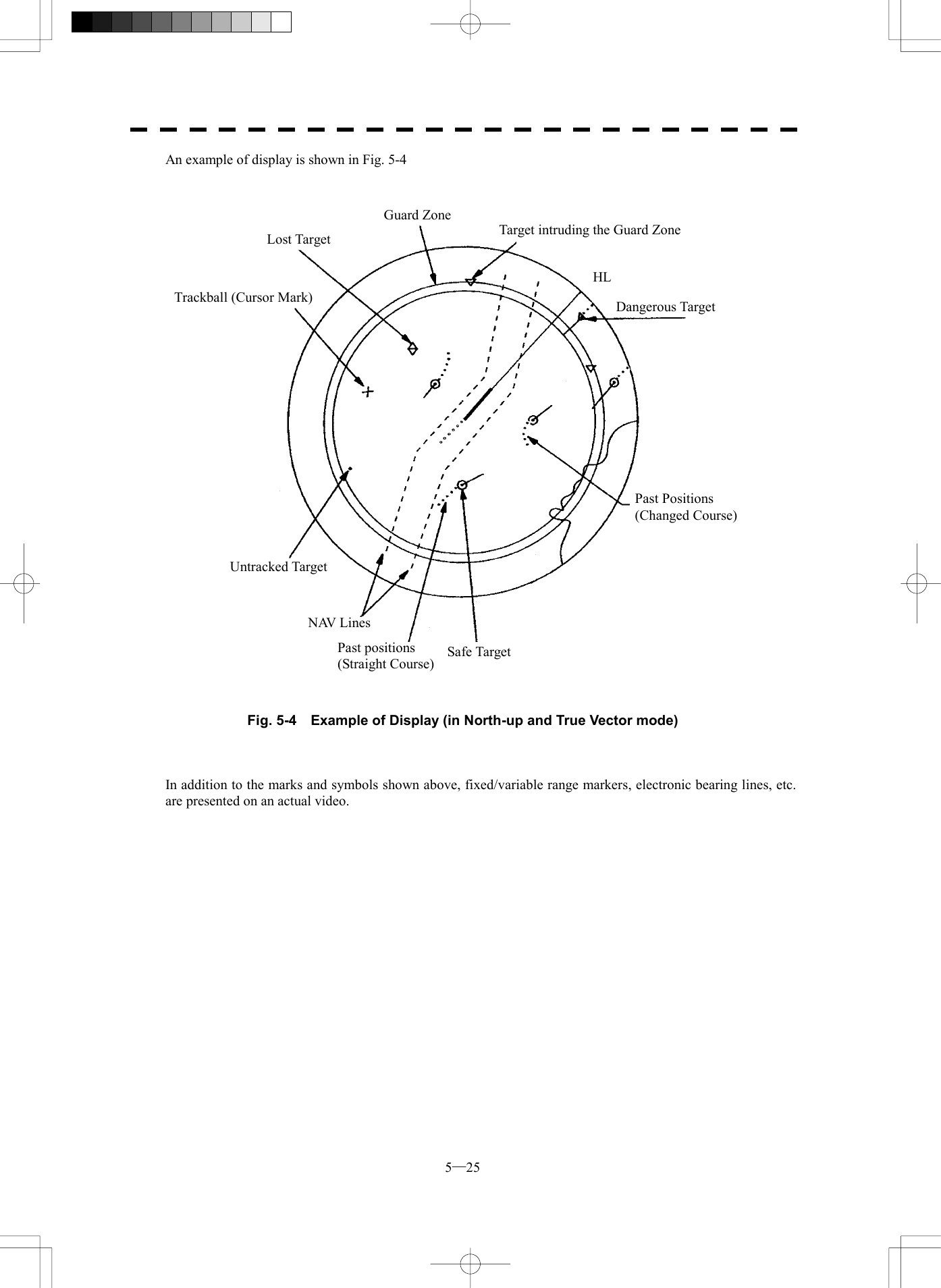
![5─21 5.3.4 ATA/ARPA Data Display (Refer to Example of Display in page 2-1. ) Display of Vectors A vector to represent a target’s predicted position can presented in the True vector or Relative vector mode. In each mode, a vector length can be freely changed for a time interval of 1 to 60 minutes. The True and Relative vector can be switched by using buttons47 shown in the radar display on page 2-7. [I] Vector Mode Selection True Vector Mode In the true vector mode, the direction of a target vector indicates the true course of the target and its vector length is proportional to its speed. In this mode, own ship’s vector is displayed as shown below. In this mode, the movements of other ships around own ship can be accurately and easily monitored. However, no CPA RING can appear in this mode. l When a target or own ship changes a course, or whena target is acquired, its vector may not reach a given level of accuracy until three minutes or more has passed after such course change or target acquisition. Even if three minutes or more has passed, the vector may include an error depending upon the tracking conditions. AttentionOwn Ship’s Vector True VectorThe relative vector is not displayedHL](https://usermanual.wiki/Japan-Radio/NKE2252.Instruction-manual-2-of-3/User-Guide-482879-Page-30.png)
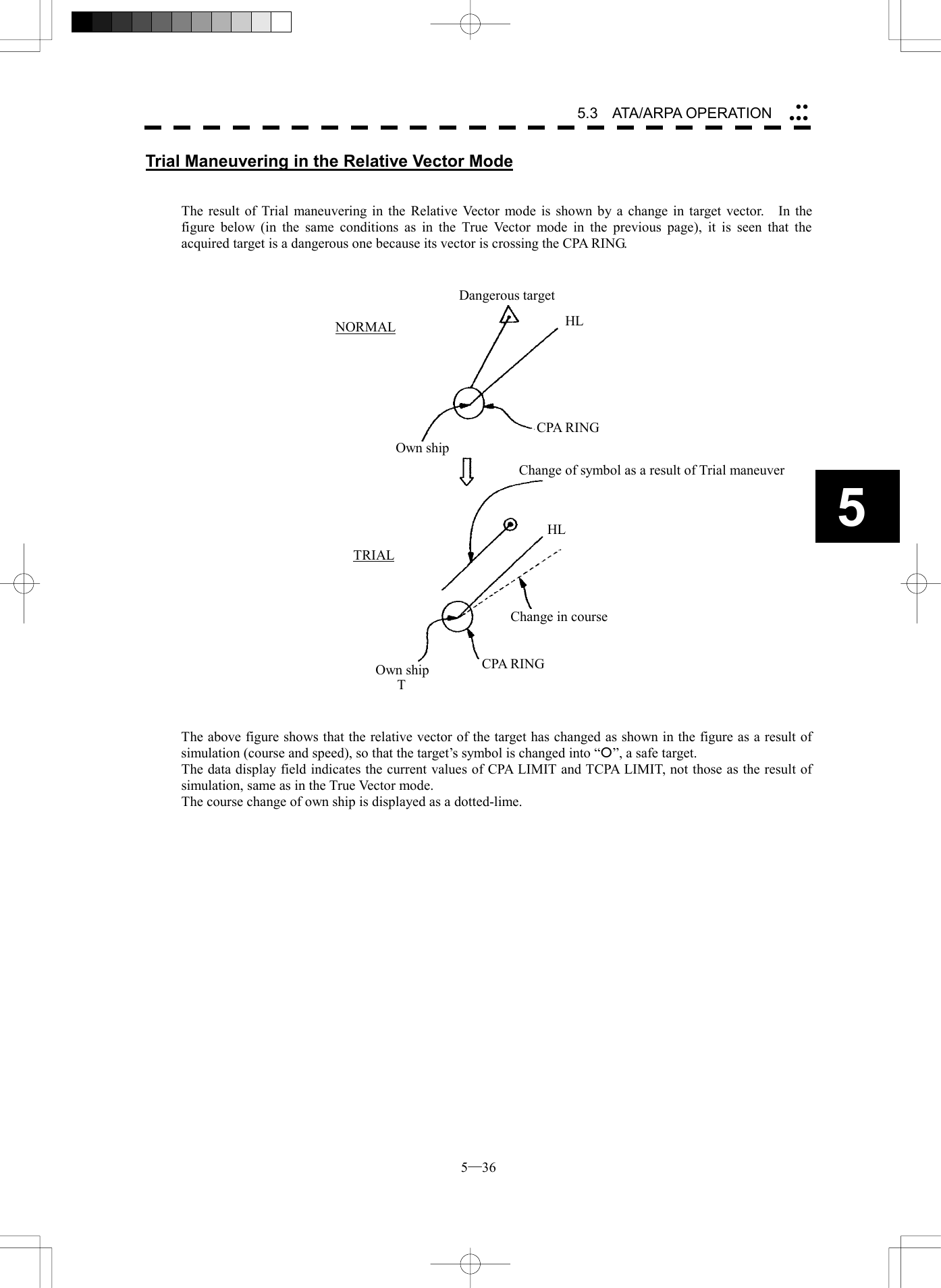
![5─22 5.3 ATA/ARPA OPERATION 5Relative Vector Mode In displaying the relative vector of a target, press the [VECT R/T] key to select the Relative Vector mode. The relative vector does not represent the true motion of the target, but its relative relation with own ship. This means that a target with its relative vector directed to own ship (passing through the CPA LIMIT ring) will be a dangerous target. In the Relative Vector mode, it can be seen at a glance where the CPA LIMIT of the dangerous target is. Therefore, the TRUE/REL mode shall optionally be used for the purpose of observation: the TRUE vector mode for grasping the true aspect of a target, and the REL vector mode for grasping a target’s closest point of approach (CPA) CPA ringRelative VectorThe true vector is not displayed HL](https://usermanual.wiki/Japan-Radio/NKE2252.Instruction-manual-2-of-3/User-Guide-482879-Page-31.png)
![5─23 [II] Vector Length: VECTOR TIME The vector length of a target is proportional to its speed, and the vector time can be switched in a range of 1 to 60 minutes by used for ten-key. The diagram below illustrates a vector length of a target for six minutes, and the tip of the vector represents the target’s position expected to reach six minutes later. Refer to Section 5.1.4 Setting Vectors for how to change the vector time. Current Position Future Predicted Position (6 min later in this example)HL](https://usermanual.wiki/Japan-Radio/NKE2252.Instruction-manual-2-of-3/User-Guide-482879-Page-32.png)
![5─24 5.3 ATA/ARPA OPERATION 5ATASetting1. Vector Time6 min2. Past PositionOFF3. CPA Limit10 nm4. TCPA Limit1 nm5. CPA RingON6. TRIAL 9. Target Number DisplayON0. EXIT1. OFF2. 0.5 min3. 1 min4. 2 min5. 4 min6. 0.1 nm7. 0.2 nm8. 0.5 nm9. 1 nmDisplay of Past Positions [PAST POSN] Procedures 1 Press [ATA MENU] key. 2 Press [1] key. The ATA Setting menu will appear. 3 Press [2] key. The Past Position screen will appear. 4 Select the past position display interval to be set, pressing the numeric key. The selected past position display interval will be set. OFF: Hides past positions. Time/Range: Past positions are displayed at the set intervals. The ATA/ARPA Past Position function can display up to 6 past positions of a target. The display interval can be set to specified time intervals of 0.5, 1, 2, or 4 minutes, or specified range intervals of 0.1, 0.2, 0.5, or 1 nm. The specified interval is shown on the right of PAST POSN in the ARPA information display area. When OFF is shown, Past Position is set to OFF in the menu. Switching between the True and Relative Vector modes takes place at the same time the vector mode is switched. In relative mode, target’s relative tracks displayed. HL](https://usermanual.wiki/Japan-Radio/NKE2252.Instruction-manual-2-of-3/User-Guide-482879-Page-33.png)
![5─26 5.3 ATA/ARPA OPERATION 55.3.5 Target Data Display Type of Data Display Target Data Target identification (TGT ID) ID number of the target True bearing: BEARING 0.1° unit Range: RANGE 0.1 NM unit True course: COURSE 0.1° unit True speed: SPEED 0.1 knot unit Closest point of approach (CPA) 0.1 NM unit Time to CPA (TCPA) 0.1 min unit Bow crossing range (BCR) 0.1 NM unit Bow crossing time (BCT) 0.1 min unit The target for which its numeric data is displayed is marked with a symbol “ ” to distinguish from other targets. If a target’s data is displayed, but without the symbol “ ”, such a target exists outside the currently displayed radar display. [I] Method of Displaying Target Data [TGT DATA] Procedures 1 Move the cross cursor mark onto the target for which numeric data is to be displayed, and press the [TGT DATA] key. Then, the data of the designated target will appear, it will be marked with a symbol “ ”. The target data will remain on the radar display until the target is lost and its vector disappears, or until another target is designated. If a target with the mark “ ” is designated, only its true bearing (BEARING) and range (RANGE) will appear until its vector appears. * Buttons and on the radar display on page 2-7 are available to switch target numbers of numeric data. l When a target or own ship changes its course, or when a newtarget is acquired, its vector may not reach a given level of accuracy until three minutes or more has passed after such course change or target acquisition. Even if three minutes or more has passed, the vector may include an error depending upon the. tracking conditions. Attention5152](https://usermanual.wiki/Japan-Radio/NKE2252.Instruction-manual-2-of-3/User-Guide-482879-Page-35.png)
![5─27 ATA Target INFO 1. Name 2. Track Color Target ID 0. EXIT [II] Input of target information (ATA Target INFO) This radar enables name inputs and target track color changes for individual ATA/ARPA targets acquired. * EPA is not available to make this setting. Procedures 1 Turn OFF the cursor mode. Button on the radar display is available to change the cursor mode. 2 Place the cursor over the target and then press [CLR/INFO] key. The ATA Target INFO screen opens. * This function is available only when the cursor mode is set to OFF. Target information screen Item overview Target ID: Target ID currently selected. Name: The name of the target. It is blanked in the initial status. The user is to enter a name. Track Color: Determines a target track color. 19](https://usermanual.wiki/Japan-Radio/NKE2252.Instruction-manual-2-of-3/User-Guide-482879-Page-36.png)
![5─28 5.3 ATA/ARPA OPERATION 5Name entry (Name) Procedures 1 While the ATA Target INFO screen is open, press [1] key. 2 For the entry of a new name ® 2. INPUT For the selection of a name from names that have already been entered ® 1. DATA BASE. For new entry Selecting INPUT displays the screen shown below. After making an entry, place the cursor over [ENT] key and then press it. When the name entered with INPUT is changed to a target name, it is saved in DATA BASE. * Up to eight characters can be entered as a name. For calling a name from the names that have been entered Selecting DATA BASE lists INPUT names that have already been entered. From the list, select a name you want to use. * Names for 30 ships can be saved in DATA BASE. 1 234 5 6 7 8 90 B CDE F G H I JA L M N O P Q R S TK V W X Y Z SP < >U DEL ENT BS NameEXITATA Target INFO 1. Name 2. Track Color Target ID 0. EXIT1. DATA BASE2. INPUT3. OFF](https://usermanual.wiki/Japan-Radio/NKE2252.Instruction-manual-2-of-3/User-Guide-482879-Page-37.png)
![5─29 1. OFF2. 1-CYAN3. 2-WHITE4. 3-BULE5. 4-GREEN6. 5-YELLOW7. 6-RED8. 7-PINK9. NEXT PageATA Target INFO 1. Name 2. Track Color Target ID 0. EXIT Track Color Setting (Track Color) Procedures 1 While the ATA Target INFO screen is open, press [2] key. 2 Pressing numeric key(s), select a color number you want to set. Colors selectable with Track Color are colors that have been set within the ATA Track Setting. When colors are set, individual colors can be set for 10 ships. For the 11th to 20th ships, 10 ships are to be set collectively. On this screen, selection of the 1st track is to select CYAN. For target tracks, up to 20 ships can be displayed. For color settings selected with Track Color, see page 5-45 in Section 5.3.9.](https://usermanual.wiki/Japan-Radio/NKE2252.Instruction-manual-2-of-3/User-Guide-482879-Page-38.png)
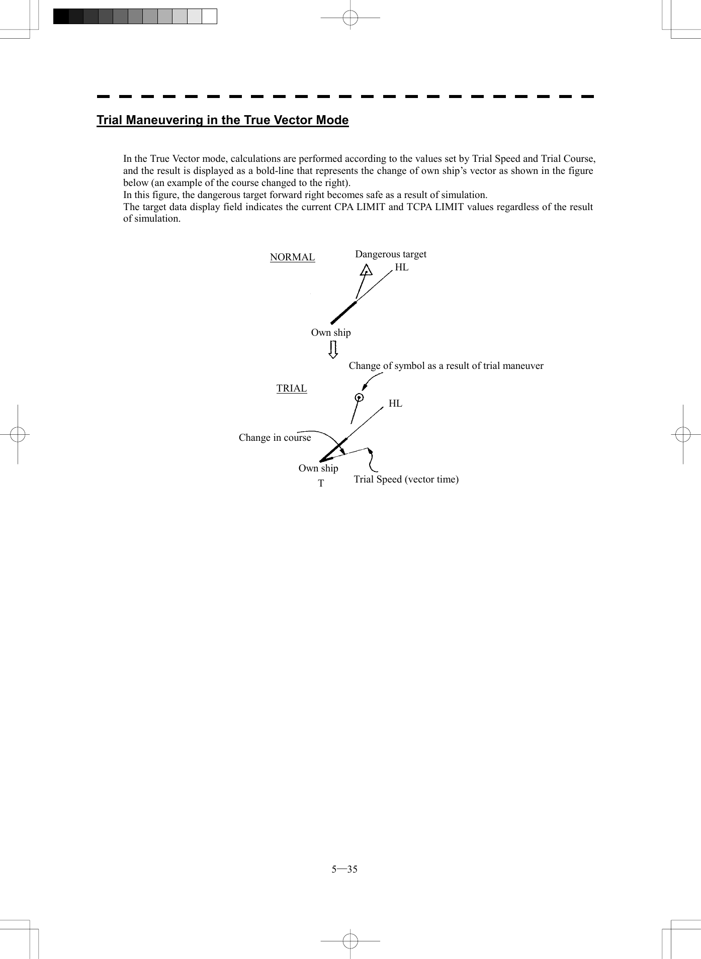
![5─34 5.3 ATA/ARPA OPERATION 55.3.7 Trial Maneuvering (Trial) Attention: Trial maneuvering can be done only when the ARPA option is installed. Trial maneuvering is unavailable if the ATA option is installed. The trial maneuvering is the function of simulating own ship’s course and speed for collision avoidance when a dangerous target appears. When manually entering own ship’s course and speed against the data of the acquired target, it is checked whether the situation is dangerous or not. The ranges of course and speed to be entered manually: Course: 360° (in 0.1° intervals)........................................................................... [EBL] control Velocity: 0 to 100 knots (in 0.1 knot steps)........................................................... [VRM] control l Trial maneuvering is to simulate own ship’s course and speed in the conditions that the course and speed of a target ship are unchanged as they are. As the situation is different from any actual ship maneuvering, set values with large margins to CPA Limit and TCPA Limit. Attention](https://usermanual.wiki/Japan-Radio/NKE2252.Instruction-manual-2-of-3/User-Guide-482879-Page-43.png)
![5─37 Trial1. Trial OFF2. Course000.0°3. Speed 20.0 kts 0. EXIT Executing the TRIAL Function Procedures 1 Press [ATA MENU] key. 2 Press [1] key. 3 Press [6] key. The TRIAL Menu will appear. 4 Press [1] key. “Trial” will be set to “ON” and a character “T” blinks under own ship’s mark on display to indicate the trial maneuvering mode. 5 Set a course by rotating the [EBL] control and a speed by rotating the [VRM] control. 6 As the symbol of plot data, dangerous target is marked with “ ” and a safe target with “¡“. Exit 1 Press [1] key. “Trial” will be set to “OFF” and the normal display will be restored.](https://usermanual.wiki/Japan-Radio/NKE2252.Instruction-manual-2-of-3/User-Guide-482879-Page-46.png)
![5─38 5.3 ATA/ARPA OPERATION 55.3.8 ATA/ARPA Simulation CAUTION Simulation is a function to check whether the ATA/ARPA system is operating normally. Do not use this function except when checking the ATA/ARPA operation. In particular, if this mode is used during navigation, pseudo targets appear on the radar display, which may be confused with the actual targets. Do not use this mode during navigation. Otherwise, this may cause accidents. The following simulation to be used for ATA/ARPA can be referred to and modified: [I] Test Video: Test video for use in checking the operation of the target detection circuit. [II] ATA Simulator: Pseudo targets are generated on the radar display to check whether the ARPA functions are operating normally. [III] Status: Displays the ATA status. [IV] Gate Display: Gate size to acquire and track targets.](https://usermanual.wiki/Japan-Radio/NKE2252.Instruction-manual-2-of-3/User-Guide-482879-Page-47.png)
![5─39 ATA TEST MENU1. Test VideoOFF2. ATA SimulatorOFF3. Status 4. Gate DisplayOFF 0. EXIT OFF1. VDG2. VDH3. VDL4. VDIN5. [I] Test Video Test Video is used to check whether the video signals under target acquisition and tracking are inputted to and processed in the target processing circuit normally. However, it is sufficient to check that VDH in TEST VIDEO is displayed. The start of the Test Video mode is available only in the Standby mode. Procedures 1 Press [STBY] key. The equipment will enter the standby state. 2 Press [ATA MENU] key. Press [5] key. The ATA Test Menu will appear. 3 Press [1] key. The Test Video setting screen will appear. 4 Press a numeric key to select a video signal you want to set. The selected test video will be set. The test video is displayed in the background of the radar display. In general, VDH is sufficient for target display checks in test video mode. If any target displayed clearly in the radar display is not displayed in the Test Video mode, the target detection circuit of the ARPA system may have a trouble. l TEST VIDEO may not appear for targets that are not acquired nor tracked, or if the [GAIN] and [SEA] controls are adjusted properly Attention](https://usermanual.wiki/Japan-Radio/NKE2252.Instruction-manual-2-of-3/User-Guide-482879-Page-48.png)
![5─40 5.3 ATA/ARPA OPERATION 5ATA TEST MENU1. TEST VideoOFF2. ATA SimulatorOFF3. Status4. Gate DisplayOFF 0. EXITOFF1.SCENARIO12.SCENARIO23.SCENARIO34.SCENARIO45.SCENARIO56.SCENARIO67.[II] ATA Simulator Pseudo targets can be generated in certain known positions to check whether the ARPA processing circuits are operating normally. Since the pseudo targets move depending on known parameters, the values for these pseudo targets can be compared with the known value if the pseudo targets are acquired and tracked, and displayed. Thus, it can be checked if the ARPA system is operating normally. Procedures 1 Press the [STBY] key. The equipment will enter the standby state. 2 Press [ATA MENU] key. Press [5] key. The ATA Test Menu will appear. 3 Press [2] key. The ATA Simulator screen will appear. 4 Select the simulator to be set, pressing the numeric key. The selected simulator will be set. 5 Press the [TX/PRF] key. The simulator will be activated and generate pseudo targets. The characters "XX" at the bottom of the radar display blinks indicating that the simulation mode is active. ARPA simulator/scenario TARGET START POINT TARGET END POINT SCENARIO DISTANCE BEARING DISTANCE BEARING TARGET SPEED 1 3.2NM 10° 1NM 90° 20kts 2 6NM 0° 0NM 0° 10kts 3 6NM every 18° 1NM every 18° 10kts 4 6NM 45° 1NM 45° 105kts 5 6NM 45° 6NM 150° 20kts 6 6NM 45° 6NM 150° 20kts Note: When the range between own ship and the pseudo target is 0, the target will disappear.](https://usermanual.wiki/Japan-Radio/NKE2252.Instruction-manual-2-of-3/User-Guide-482879-Page-49.png)
![5─41 Exit 1 Press the [STBY] key. The equipment will enter the standby state. 2 Press [2] key while the ATA Test Menu is open. The ATA Simulator screen will appear. 3 Press [1] key to select OFF. The ATA Simulator is turned off.](https://usermanual.wiki/Japan-Radio/NKE2252.Instruction-manual-2-of-3/User-Guide-482879-Page-50.png)
![5─42 5.3 ATA/ARPA OPERATION 5Status* Constant 5* Video Level TD* Video Level HI* Video Level Low* Gate Size* Tracking 0. EXIT1581NARROW1[III] Status The current ATA/ARPA status will appear. Procedures 1 Press [ATA MENU] key. The ATA Menu will appear Press [5] key. The ATA Test Menu will appear. 2 Press [3] key. The Status screen will appear.. *Constant: Vector response *Video Level TD: Threshold value used for tracking *Video Level HI: VD threshold value used for guard zone *Video Level Low: Unused *Gate Size: Size of gate used for tracking *Tracking: Number of targets currently acquired](https://usermanual.wiki/Japan-Radio/NKE2252.Instruction-manual-2-of-3/User-Guide-482879-Page-51.png)
![5─43 ATA TEST MENU1. TEST VideoOFF2. ATA SimulatorOFF3. Status4. Gate DisplayOFF 0. EXIT [IV] Gate Display The gate displays an area monitoring a target using the ATA/ARPA function. This radar equipment allows the gate size to change automatically according to target distance and size. User can check the gate size using the following function. Procedures 1 Press [ATA MENU] key. Press [5] key. The ATA Test Menu will appear. 2 Press [4] key. The gate display mode is switched. ON: Gate is displayed OFF: Gate is not displayed 3 The gate displays data of a target you want to check using the cursor and [TGT DATA] key. (See Section 5.3.5 Target Data Display.) The data is displayed, and the gate is displayed around the ATA/ARPA symbol in green. Note: The ATA/ARPA function can display the gate of two targets simultaneously. ARPA/ATA symbol Vector Echo Gate (displayed in green)](https://usermanual.wiki/Japan-Radio/NKE2252.Instruction-manual-2-of-3/User-Guide-482879-Page-52.png)
![5─44 5.3 ATA/ARPA OPERATION 5ATA Track Setting1. Track FunctionON2. Track Color >3. Track Display >4. Track Memory Interval3 sec5. Clear Track ColorWHITE6. Clear Track Number7. Card2 Track Display00000. EXITWHITE5.3.9 Setting ATA/ARPA Tracks (ATA Track Setting) Track information on acquired ATA/ARPA targets can be set. This radar can acquire target tracks of up to 20 ships. [I] Turning ON/OFF the target track function (Track Function) Procedures 1 Press [ATA MENU] key. 2 Press [3] key. The ATA Track Setting Menu will appear. 3 Press [1] key. The ATA/ARPA Track function is switched between ON and OFF. ON: Sets the ATA/ARPA Track function to ON. OFF: Sets the ATA/ARPA Track function to OFF. * When this function turn off, all target track functions to OFF(Including track memory), If so, checking cannot be done later.](https://usermanual.wiki/Japan-Radio/NKE2252.Instruction-manual-2-of-3/User-Guide-482879-Page-53.png)
![5─45 Track Color1. All 2. ATA Track No.13. ATA Track No.24. ATA Track No.3PINK5. ATA Track No.4RED6. ATA Track No.57. ATA Track No.6OFF0. EXIT WHITE8. ATA Track No.79. NEXT INDIVIDUALYELLOWGREENCYAN1. INDIVIDUAL2. WHITE3. CYAN4. BLUE5. GREEN6. YELLOW 7. PINK 8. RED 9. NEXT[II] Setting target track colors (Track Color) The same color can be selected for all target tracks, or different colors can be set to ships whose track numbers are 1 to 10. In such cases, 10 ships, whose track numbers are 11 to 20, are to be set collectively. Procedures 1 Press [2] key while the ATA Track Setting Menu is open. Track color can be set. 2 Press [1] key. Which is to be selected, setting individual colors or setting the same color for all ships, is to be determined depending on the setting for the ALL item. Setting individual colors: Select INDIVIDUAL Setting the same color for all ships: Select a color number For setting individual colors Selecting INDIVIDUAL makes it effective to set track numbers from ATA Track No.1 to ATA Track No.10 as well as individual settings for Other. Set a color for each target. When pressing the item number of the target to be set displays a list of colors, select desired colors from the list. Eight colors are selectable: OFF, WHITE, CYAN, BLUE, GREEN, YELLOW, PINK and RED. ATA Track No.1 to ATA Track No.10: 1st ship to 10th ship Other: 11th ship to 20th ship Settings are made as shown above. * Note that individual settings are effective only when INDIVIDUAL has been set. For setting the same color for all ships This setting is determined when you select a color displayed with ALL selected. The types of colors are the same as those to be used for setting individual colors.](https://usermanual.wiki/Japan-Radio/NKE2252.Instruction-manual-2-of-3/User-Guide-482879-Page-54.png)
![5─46 5.3 ATA/ARPA OPERATION 5Track Display1. All 2. ATA Track No.13. ATA Track No.24. ATA Track No.3ON5. ATA Track No.4ON6. ATA Track No.57. ATA Track No.6ON0. EXITON8. ATA Track No.6ON9. NEXTONONINDIVIDUAL1. INDIVIDUAL2. ON3. OFF[III] Setting Display of Target Tracks (Track Display) The display of target tracks can be set to ON/OFF. For the display of tracks, setting for display/nondisplay of all ships or for individual ships can be made. Procedures 1 Press [3] key while the ATA Track Setting Menu is open. Track display can be set. 2 Press [1] key. Which is to be selected, setting individual tracks or display/nondisplay for all ships, is to be determined depending on the setting for the ALL item. Setting individual tracks: Select INDIVIDUAL Setting display for all ships: Select ON Setting nondisplay for all ships: Select OFF For setting individual tracks Selecting INDIVIDUAL makes it effective to set track numbers from ATA Track No.1 to ATA Track No.10 as well as individual settings for Other. Select display/nondisplay for each target. Each time ON/OFF window is pressed, a decision branch is switched to another. ATA Track No.1 to ATA Track No.10: 1st ship to 10th ship Other: 11th ship to 20th ship Settings are made as shown above. * Note that individual settings are effective only when INDIVIDUAL has been set.](https://usermanual.wiki/Japan-Radio/NKE2252.Instruction-manual-2-of-3/User-Guide-482879-Page-55.png)
![5─47 ATA Track Setting1. Track Function2. Track Color >3. Track Display >4. Track Memory Interval3 sec5. Clear Track ColorWHITE6. Clear Track Number7. Card2 Track Display00000. EXIT 00001. OFF2. 3 sec3. 5 sec4. 10 sec5. 30 sec6. 1 min7. 3 min8. 5 min9. NEXT[IV] Setting target track memory intervals (Track Memory Interval) Target track memory intervals can be set. * Note that this function is available only when the Target Track function is set to ON. Procedures 1 Press [4] key while the ATA Track Setting Menu is open. The Track Memory Interval setting items are displayed. 2 Select a number for a memory interval you want to set. Settable intervals Select from the following intervals: OFF, 3 sec, 5 sec, 10 sec, 30 sec, 1 min, 3 min, 5 min, 10 min, 30 min, 60 min, 1 nm, 3 nm, 5 nm and 10 nm * Setting this function to ON saves target tracks even though Target Display is set to OFF.](https://usermanual.wiki/Japan-Radio/NKE2252.Instruction-manual-2-of-3/User-Guide-482879-Page-56.png)
![5─48 5.3 ATA/ARPA OPERATION 5ATA Track Setting1. Track Function2. Track Color >3. Track Display >4. Track Memory Interval3 sec5. Clear Track Color6. Clear Track Number7. Card2 Track Display00000. EXIT WHITEWHITE1. ALL2. WHITE3. CYAN4. BLUE5. GREEN6. YELLOW7. PINK8. RED9. NEXT[IV] Erasing target tracks (Clear Track) Target tracks can be erased. You can select an erasing method by color setting or an erasing method by track number setting. Erasing tracks by color setting (Clear Track Color) Procedures 1 Press [5] key while the ATA Track Setting Menu is open. 2 Select the number of the color you want to erase.](https://usermanual.wiki/Japan-Radio/NKE2252.Instruction-manual-2-of-3/User-Guide-482879-Page-57.png)
![5─49 ATA Track Setting1. Track Function2. Track Color >3. Track Display >4. Track Memory Interval3 sec5. Clear Track Color6. Clear Track Number7. Card2 Track Display00000. EXIT WHITE11. ALL2. ATA Track No.13. ATA Track No.24. ATA Track No.35. ATA Track No.46. ATA Track No.57. ATA Track No.68. ATA Track No.79. NEXT PageErasing tracks by track number (Clear Track Number) Procedures 1 Press [6] key while the ATA Track Setting Menu is open. 2 Select the track number you want to erase.](https://usermanual.wiki/Japan-Radio/NKE2252.Instruction-manual-2-of-3/User-Guide-482879-Page-58.png)
![5─50 5.3 ATA/ARPA OPERATION 5ATA Track Setting1. Track Function2. Track Color >3. Track Display >4. Track Memory Interval3 sec5. Clear Track Color6. Clear Track Number7. Card2 Track Display00000. EXITWHITE1[V] Reading target track saved in CARD2 (Card2 Track Display) Saved target tracks can be read from CARD2. Reading targets by color setting Procedures 1 Press [7] key while the ATA Track Setting Menu is open. 2 Enter the number you want to read with the numeric key, and then press the ENT key. * For how to save targets in CARD2, see page 3-131, section 3.12.1.](https://usermanual.wiki/Japan-Radio/NKE2252.Instruction-manual-2-of-3/User-Guide-482879-Page-59.png)
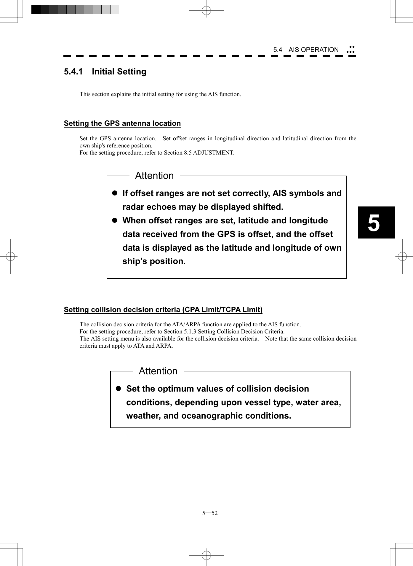
![5─51 5.4 AIS OPERATION * Use of this function requires AIS I/F (option). There are the following limitations on use of the AIS function, system, and operation: [I] This system can display a maximum of 50 AIS targets. Thereare two types of filters for increasing the display priority. (Refer to Section 5.4.6 AIS FILTER SETTING.) [II] Keep in mind that the following restrictions are placed on useof the AIS function: 1) The AIS function cannot be turned on in the following cases: · MANUAL is selected for the speed sensor. · LOG or 2-axis LOG is used for the speed sensor, and SET and DRIFT are selected. 2) LOG or 2-axis LOG cannot be selected for the speed sensor inthe following case: · SET or DRIFT is set while the AIS function is on. 3) MANUAL cannot be selected for the speed sensor in the following case: · The AIS function is on. 4) SET/DRIFT (current offset) cannot be turned on in the followingcase: · The AIS function is turned on, and LOG or 2-axis LOG is selected for the speed sensor. Attention](https://usermanual.wiki/Japan-Radio/NKE2252.Instruction-manual-2-of-3/User-Guide-482879-Page-60.png)
![5─53 AIS Setting1. AIS FunctionOFF2. AIS Symbol DisplayOFF3. ATA Symbol DisplayON4. CPA Limit1 nm5. TCPA Limit1 min6. AIS Filter Setting >7. Identical Distance100 m0. EXIT Procedures 1 Press [ATA MENU] key. 2 Press [2] key. The AIS Setting Menu will appear. 3 Press [4] key. The ten-key screen will appear. 4 Using numeric keys, enter the CPA value you want to set, and then press [ENT] key. The entered CPA Limit value is determined. 5 Press [5] key. The ten-key screen will appear. 6 Using numeric keys, enter the TCPA value you want to set, and then press [ENT] key. The entered TCPA Limit value is determined. * The collision decision criteria set on the AIS side are also available on ATA/ARPA.](https://usermanual.wiki/Japan-Radio/NKE2252.Instruction-manual-2-of-3/User-Guide-482879-Page-62.png)
![5─54 5.4 AIS OPERATION 55.4.2 Setting AIS Display Function (AIS Function) Switch the AIS symbol display function to ON/OFF. Procedures 1 Press [ATA MENU] key. Press [2] key. The AIS Setting menu will appear. 2 Press [1] key. The AIS Function is switched between ON and OFF. ON: Enables the AIS display function. OFF: Disables the AIS display function. * Button on the radar display on page 2-7 is also available to switch the display functions. * Note that turning OFF this function switches all AIS display functions to OFF. l When the AIS display function is set to OFF, no AIS symbols are displayed. l The AIS display function itself is turned OFF. l Once the AIS display function is set to OFF, it is not automatically switched to ON even if a dangerous target exists. AttentionAIS Setting1. AIS FunctionOFF2. AIS Symbol DisplayOFF3. ATA Symbol DisplayON4. CPA Limit1 nm5. TCPA Limit1 min6. AIS Filter Setting >7. Identical Distance100 m 0. EXIT 25](https://usermanual.wiki/Japan-Radio/NKE2252.Instruction-manual-2-of-3/User-Guide-482879-Page-63.png)
![5─55 5.4.3 Activating AIS Targets Activate an AIS target, and display the target’s vector and make a collision decision. Manual activation Activate an AIS target*1 in manual mode to display the vector and HL. Procedures 1 Press the CURSOR button at the upper right of the radar display several times until ACT AIS appears. The cursor mode is set to the AIS activation mode. 2 Move the cross cursor mark onto the inactive AIS target that is to be activated*1, and press [ENT] key. The selected AIS target will be activated*1. Automatic activation Activate an AIS target in automatic mode to display the vector and HL. If the guard zone function is in use, an AIS target is activated automatically when it has entered the guard zone. Dangerous targets are also activated automatically. The guard zone is the same as for ATA/ARPA. For the setting procedure, refer to “Setting Guard Zone” in 3.4 BASIC OPERATION of the instruction manual. Reference If an AIS target is activated but the vector is not displayed, refer to Section 5.4.5 Setting AIS Symbol Display. *1 For activation of targets, refer to Section 5.1.2 Definitions of Symbols.](https://usermanual.wiki/Japan-Radio/NKE2252.Instruction-manual-2-of-3/User-Guide-482879-Page-64.png)
![5─56 5.4 AIS OPERATION 5 l The operation above is effective only for active targets. 5.4.4 Deactivating AIS Targets Deactivate an AIS target*2 and clear the display of the vector and HL. Procedures 1 Press the CURSOR button at the upper right of the radar display several times until CANCEL appears. The cursor mode is set to the deactivation mode. 2 Move the cross cursor mark onto the active AIS target that is to be deactivated*2, and press [ENT] key. The selected AIS target will be deactivated*2 . *2 For deactivation of targets, refer to Section 5.1.2 DEFINITIONS OF SYMBOLS. Attention](https://usermanual.wiki/Japan-Radio/NKE2252.Instruction-manual-2-of-3/User-Guide-482879-Page-65.png)
![5─57 5.4.5 Setting AIS Symbol Display Function (AIS Symbol Display) Switch ON or OFF to set the AIS symbol display function. Procedures 1 Press [ATA MENU] key. Press [2] key. The AIS Setting menu will appear. 2 Press [2] key. The AIS Symbol Display is switched between ON and OFF. ON: Enables the AIS symbol display function. OFF: Disables the AIS symbol display function. * Button on the radar display on page 2-7 is also available for switching. AIS Setting1. AIS FunctionOFF2. AIS Symbol DisplayOFF3. ATA Symbol DisplayON4. CPA Limit1 nm5. TCPA Limit1 min6. AIS Filter Setting >7. Identical Distance100 m 0. EXIT 26](https://usermanual.wiki/Japan-Radio/NKE2252.Instruction-manual-2-of-3/User-Guide-482879-Page-66.png)
![5─58 5.4 AIS OPERATION 55.4.6 Displaying Numeric Data of AIS Targets Display the numeric data of active AIS targets. Types of numeric data displayed There are two modes (simple and detail) to display the numeric data of AIS targets. The display items are different between the two modes. Display Item Detail mode Simple mode NAME (ship name) Up to 20 characters CALL SIGN Up to 7 characters MMSI Up to 9 characters COG (course over ground) 0.1° unit SOG (speed over ground) 0.1 knot unit CPA (closest point of approach) 0.1 nm unit TCPA (time to CPA) 0.1 min unit BRG (true bearing) 0.1° unit RANGE 0.1 nm unit HDG (heading bearing) 0.1° unit ROT (course change speed) 0.1°/min L/L (latitude/longitude) 0.001’ unit Not displayed The detail mode displays the numeric data of only a single ship; the simple mode can display the numeric data of up to three ships. Displaying numeric data Procedures 1 Press the CURSOR button at the upper right of the radar display several times until TGT DATA appears. The cursor mode is set to the numeric data display mode. 2 Move the cross cursor mark onto the active AIS target for which numeric data is to be displayed, and press [ENT] key. The values of the selected AIS target will appear on the right side of the radar display. The mark is displayed around the symbol. Reference: If the values are displayed but the mark . is not on the radar display, the target is outside the radar display.](https://usermanual.wiki/Japan-Radio/NKE2252.Instruction-manual-2-of-3/User-Guide-482879-Page-67.png)
![5─59 Clearing numeric data Procedures 1 Press the CURSOR button at the upper right of the radar display several times until TGT DATA appears. The cursor mode is set to the numeric data display mode. 2 Move the cross cursor mark onto the active AIS target for which numeric data is to be cleared, and press [CLR] key. The values of the selected AIS target will be cleared from the right side of the radar display, and the mark displayed around the symbol will also disappear. Selecting the detail/simple mode to display numeric data 1 Move the pointer to the button W, W at the upper right of the AIS target’s numeric data display area, and press [ENT] key. 2 The detail mode or the simple mode is switched each time the button is clicked. Switched each time the button is clicked Display sample in detail mode Display sample in simple mode Procedures](https://usermanual.wiki/Japan-Radio/NKE2252.Instruction-manual-2-of-3/User-Guide-482879-Page-68.png)
![5─60 5.4 AIS OPERATION 55.4.7 Setting ATA/ARPA Symbol Display Function (ATA Symbol Display) Set the ATA/ARPA symbol display function to ON/OFF. This function is effective only when the AIS display function (option) is set to ON. This function is unavailable when the AIS display function is set to OFF. This function holds data even though the ATA/ARPA display is set to OFF. For the AIS display function, see Section 5.4.2 on page 5-54. Procedures 1 Press [ATA MENU] key. Press [2] key. The AIS Setting menu will appear. 2 Press [3] key. The ATA/ARPA Symbol Display Function is switched ON or OFF. ON Enables the ATA/ARPA symbol display function. OFF: Disables the ATA/ARPA symbol display function. * Button on the radar display on page 2-7 is also available to switch between ON and OFF. AIS Setting1. AIS FunctionOFF2. AIS Symbol DisplayOFF3. ATA Symbol DisplayON4. CPA Limit1 nm5. TCPA Limit1 min6. AIS Filter Setting >7. Identical Distance100 m0. EXIT 27](https://usermanual.wiki/Japan-Radio/NKE2252.Instruction-manual-2-of-3/User-Guide-482879-Page-69.png)
![5─61 5.4.8 Setting AIS Filter (AIS Filter Setting) About an AIS filter The setting of an AIS filter enables the priority display of AIS targets in the area. The filter is initially set in a circle having a radius of 20 [nm] from the own ship’s position. If 51 or more targets exist in the filter range, they are displayed according to the priority explained in Section 5.4.11 Displaying AIS Symbols - Maximum number of targets and the display priority. Type of AIS filters (Filter Type) There are the following three types of AIS filters: 1) RANGE........ A filter is set in a circle with a set range as the radius. 2) SECTOR ...... A filter is set in a sector formed by two bearings with the bow as reference. 3) ZONE........... A filter is set in a zone formed by two bearings and two ranges with the bow as reference. Procedures 1 Press [ATA MENU] key. Press [2] key. Press [6] key. The ATA Filter Setting menu will appear. 2 Press [1] key. The Filter type selection screen will appear. 3 Select the AIS filter type to be set, pressing the numeric key. The selected AIS filter type will be determined. AIS Filter Setting1. Filter TypeRANGE2. Make AIS Filter3. Filter DisplayON 0. EXIT 1. RANGE2. SECTOR3. ZONE](https://usermanual.wiki/Japan-Radio/NKE2252.Instruction-manual-2-of-3/User-Guide-482879-Page-70.png)
![5─62 5.4 AIS OPERATION 5Making an AIS filter (Make AIS Filter) Procedures 1 Press [2] key while the ATA Filter Setting menu is open. The Make AIS Filter screen will appear. [I] Setting a RANGE filter 2 Turn the [VRM] key control to set a filter range, and press [ENT] key. The range of a RANGE filter will be set. AIS targets in the set circle are displayed by priority. [II] Setting a SECTOR filter 2 Turn the [EBL] key control to set the bearing of the port side, and press [ENT] key. 3 Turn the [EBL] key control to set the bearing of the starboard, and press [ENT] key. A SECTOR filter will be set. AIS targets in the area formed by the two set bearings are displayed by priority. [III] Setting a ZONE filter 2 Turn the [EBL] key and [VRM] key controls to set the bearing and range of the port side, and press [ENT] key. 3 Turn the [EBL] key and [VRM] key controls to set the bearing and range of the starboard, and press [ENT] key. A ZONE filter will be set. AIS targets in the area formed by the two set bearings and ranges are displayed by priority. AIS Filter Setting1. Filter TypeRANGE2. Make AIS Filter3. Filter DisplayON 0. EXIT](https://usermanual.wiki/Japan-Radio/NKE2252.Instruction-manual-2-of-3/User-Guide-482879-Page-71.png)
![5─63 Setting the AIS filter display function to ON/OFF (Filter Display) Procedures 1 Press [3] key while the ATA Filter Setting menu is open. The setting of AIS Filter display will be switched ON or OFF. ON: Displays the AIS filter. OFF: Hides the AIS filter. l When the guard zone function is enabled, the system automatically corrects the filter range to cover the guard zone. Thus, the guard zone is always inside the filter range. AttentionAIS Filter Setting1. Filter TypeRANGE2. Make AIS Filter3. Filter DisplayON 0. EXIT](https://usermanual.wiki/Japan-Radio/NKE2252.Instruction-manual-2-of-3/User-Guide-482879-Page-72.png)
![5─64 5.4 AIS OPERATION 55.4.9 Deciding AIS Target and ARPA Target as the Same One (Identical Distance) Setting a range in which an AIS target and ARPA target are regarded as the same one An AIS target and an ARPA target in the set range are regarded as the same one, and the ARPA symbol is not displayed. At this time, the AIS symbol is automatically activated. Procedures 1 Press [ATA MENU] key. Press [2] key. The AIS Setting menu will appear. 2 Press [7] key. The ten-key will appear. 3 Select the distance to be set pressing the numeric key, and press [ENT] key. The range in which an AIS target and ARPA target are regarded as the same one will be set. l To display the hidden ARPA symbol, set the AIS symbol display function to OFF. (For the setting procedure, refer to Section 5.4.5) l Set 0 not to regard an AIS target and ARPA target as the same one. AttentionAIS Setting1. AIS FunctionOFF2. AIS Symbol DisplayOFF3. ATA Symbol DisplayON4. CPA Limit1 nm5. TCPA Limit1 min6. AIS Filter Setting >7. Identical Distance 0. EXIT](https://usermanual.wiki/Japan-Radio/NKE2252.Instruction-manual-2-of-3/User-Guide-482879-Page-73.png)
![5─66 5.4 AIS OPERATION 55.4.10 Conditions for Deciding AIS Target to be Lost About a lost target When the data of an AIS target cannot be received for a specified time, the target is decided to be lost and the target data is deleted. As shown in the table below, the time until target data is deleted varies depending on the class of receive data and the target status. [SOLAS ship] (Class A) Target Status Time until data deletionVessel below 3 knots and it is now at anchor or on the berth 18 min Vessel of 3 knots or more and it is now at anchor or on the berth 60 sec Vessel of 0 to 14 knots 60 sec Vessel of 0 to 14 knots and it is now changing the course 60 sec Vessel of 14 to 23 knots 36 sec Vessel of 14 to 23 knots and it is now changing the course 36 sec Vessel of 23 knots or more 12 sec Vessel of 23 knots or more and it is now changing the course 12 sec [Non-SOLAS ship] (Class B) Target Status Time until data deletionVessel below 2 knots 18 min Vessel of 2 to 14 knots 180 sec Vessel of 14 to 23 knots 90 sec Vessel of 23 knots or more 30 sec Reference: · When a dangerous target ship is lost, a lost alarm is issued and the symbol changes to a lost symbol. The system calculates the current position from the last-received data and continues displaying the symbol for a maximum of one minute. If the system cannot receive any data within one minute or the ALARM ACK switch is pressed, the symbol is cleared. · When a safe target ship is lost, the system does not issue a lost alarm, display a lost symbol, or calculate the current position.](https://usermanual.wiki/Japan-Radio/NKE2252.Instruction-manual-2-of-3/User-Guide-482879-Page-75.png)
![6─6 66.4 FALSE ECHOES The radar observer may be embarrassed with some echoes that do not exist actually. These false echoes appear by the following causes that are well known: [I] Shadow When the radar scanner is installed near a funnel or mast, the echo of a target that exists in the direction of the funnel or mast cannot appear on the radar display because the radar beam is reflected on the funnel or mast. Whether there are some false echoes due to shadows can be checked monitoring the sea clutter returns, in which there may be a part of weak or no returns. Such shadows appear always in the same directions, which the operator should have in mind in radar operation. [II] Side Lobe Effect A broken-line circular arc may appear at the same range as the main lobe of the radar beam on the radar display. This type of false echo can easily be discriminated when a target echo appears isolated. (See Figure 6.3) Figure 6.3 [III] False Echo by Secondary Reflection When a target exists near own ship, two echoes from the single target may appear on the radar display. One of those echoes is the direct echo return from the target and the other is the secondary reflection return from a mast or funnel that stands in the same direction as shown in Figure 6.4. Figure 6.4 Direct microwaveRadar scanner Funnel Actual target Secondary reflection of microwave False echo from funnel](https://usermanual.wiki/Japan-Radio/NKE2252.Instruction-manual-2-of-3/User-Guide-482879-Page-85.png)
![6─7 [IV] False Echo by Multiple Reflection When there is a large structure or ship with a high vertical surface near own ship as shown in Figure 6.5, multiple refection returns may appear on the radar display. These echoes appear in the same intervals, of which the nearest echo is the true echo of the target. Figure 6.5 [V] Abnormal Propagation The maximum radar detection range depends upon the height of the scanner and the height of a target as described in the section of “The Horizon for Radar Beam Radiation”. If a so-called “duct” occurs on the sea surface due to a certain weather condition, however, the radar beam may propagate to a abnormally long distance, at which a target may be detected by the radar. For instance, assuming that the radar range is 6 NM (on the repetition frequency of 1100 Hz), the first pulse is reflected from a target at about 76 NM or more and received during the next pulse repetition time. In this case, a false echo appears at a position that is about 76 NM shorter than the actual distance. If the false echo appears at 5 NM on the radar display, the true distance of the target is 5+76=81 NM. On the radar range scale of 1.5 NM (on the repetition frequency of 1900 Hz), a false echo may appear at a position that is about 43 NM shorter than the actual distance. This type of false echo can be discriminated by changing over the range scale (the repetition frequency), because the distance of the target changes accordingly.](https://usermanual.wiki/Japan-Radio/NKE2252.Instruction-manual-2-of-3/User-Guide-482879-Page-86.png)
![6─8 6.4 FALSE ECHOES6[VI] Radar Interference When another radar equipment using the same frequency band as that on own ship is near own ship, a radar interference pattern may appear on the radar display. This interference pattern consists of a number of spots which appear in various forms. In many cases, these spots do not always appear at the same places, so that they can be discriminated from the target echoes. (See Figure 6.6) Figure 6.6 If radar equipment causing an interference pattern and this radar are of the same model, their transmitting repetition frequency is nearly the same. As a result, interference patterns may be displayed concentrically. In this case, the interference patterns cannot be eliminated by using only the interference reflector function, so press [TX/PRF] several times to fine-tune the transmitting repetition frequency. An interference suppressing effect can be heightened by applying a different transmitting repetition frequency to the interference pattern source radar and this radar.](https://usermanual.wiki/Japan-Radio/NKE2252.Instruction-manual-2-of-3/User-Guide-482879-Page-87.png)
![6─9 6.5 DISPLAY OF RADAR TRANSPONDER (SART) The SART (Search and rescue Radar Transponder) is a survival device authorized by the GMDSS (Global Maritime Distress and Safety System), which is used for locating survivors in case that a distress accident occurs at sea. The SART is designed to operate in the 9 GHz frequency band. When receiving the 9 GHz radar signal (interrogating signal) transmitted from the radar equipment on a rescue ship or search aircraft, the SART transmit a series of response signals to inform the distress position to the rescue and search party. * This radar provides a shortcut item to make settings for SART signal reception. Execution of this item automatically switches to the setting for SART reception. Procedures 1 Press [RANGE +] or [RANGE -] to set the radar range to 6 NM or 12 NM. 2 Press [RADAR MENU]. The Main Menu will appear. 3 Press [5]. Each time the key is pressed, switching between ON and OFF takes place. MAIN MENU1. IR IR OFF2. ProcessPROC OFF3. Target EnhanceOFF4. Zoom OFF5. SART ON6. NAV Information > 8. Graphic DisplayON9. RADAR MENU(→Plot)0. EXIT](https://usermanual.wiki/Japan-Radio/NKE2252.Instruction-manual-2-of-3/User-Guide-482879-Page-88.png)
![6─10 6.4 FALSE ECHOES6With the SART display mode set to ON, settings as shown below are made automatically. (1) Sea clutter control: Minimum (Most counterclockwise) (2) AUTO SEA function: OFF (3) Rain and Snow Clutter Control (RAIN): minimum (4) Auto Rain and Snow Clutter function (AUTO RAIN): OFF (5) TUNE control: No tuning (to weaken clutter echoes) (6) Interference rejector (IR): OFF (7) PROCESS: OFF [Example of Display] SART code Position of SART Position of the rescue craft Other ships Landl When the SART function is set to ON to detect the SART signal, small targets around own ship will disappear from the radar display. So it is necessary to exercise full surveillance over the conditions around own ship by visual watch in order to avoid any collision or stranding. If two or more sets of radar equipment are installed on own ship, use one set of 9 GHz band radar for detection of the SART signal and operate others as normal radars for avoiding collision, monitoring targets around own ship, and checking on own ship’s position and avoidance of stranding. After end of detecting the START signal, turn the START display off. Then the radar returns normally to the nautical mode. Attention](https://usermanual.wiki/Japan-Radio/NKE2252.Instruction-manual-2-of-3/User-Guide-482879-Page-89.png)
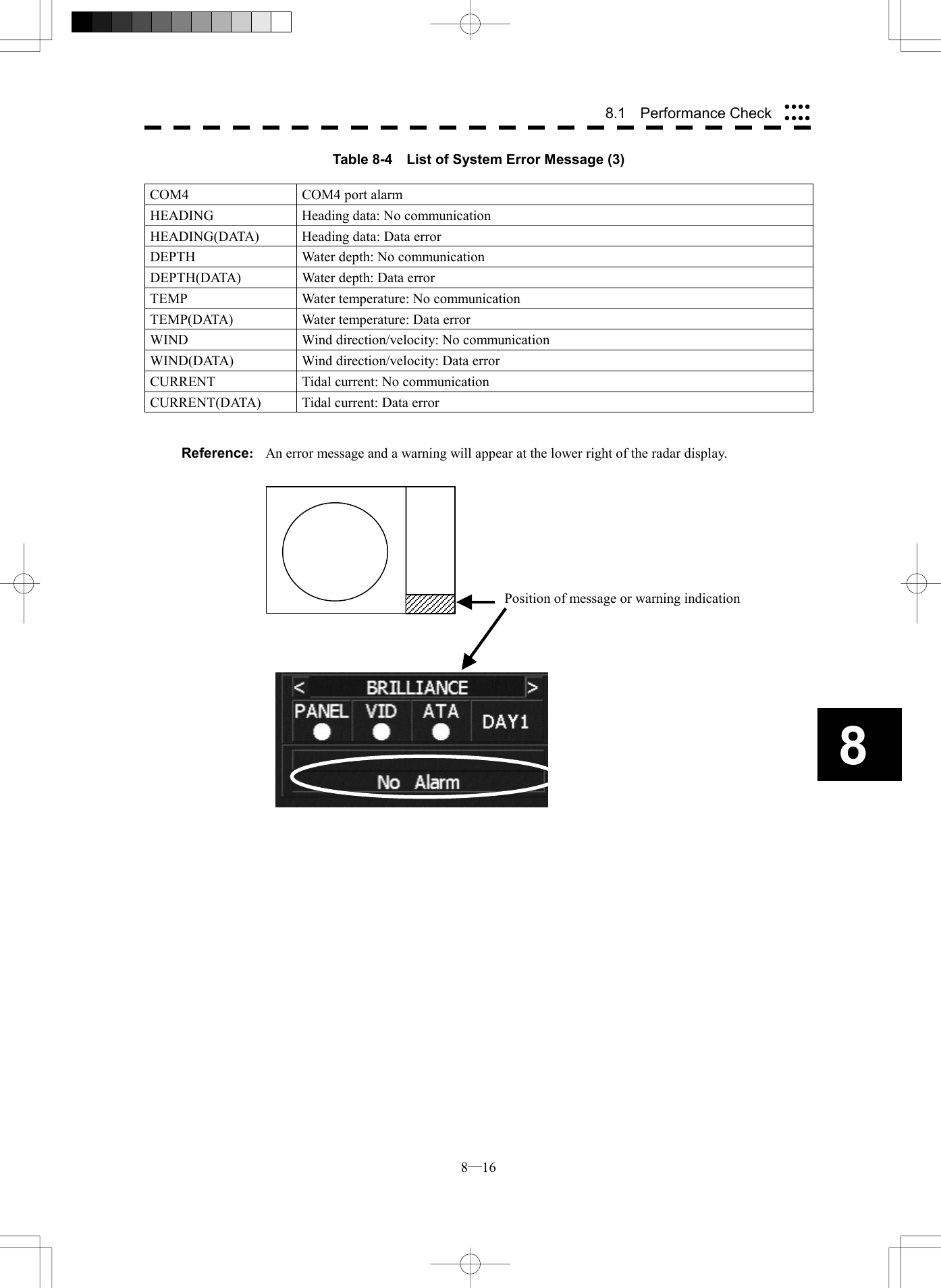
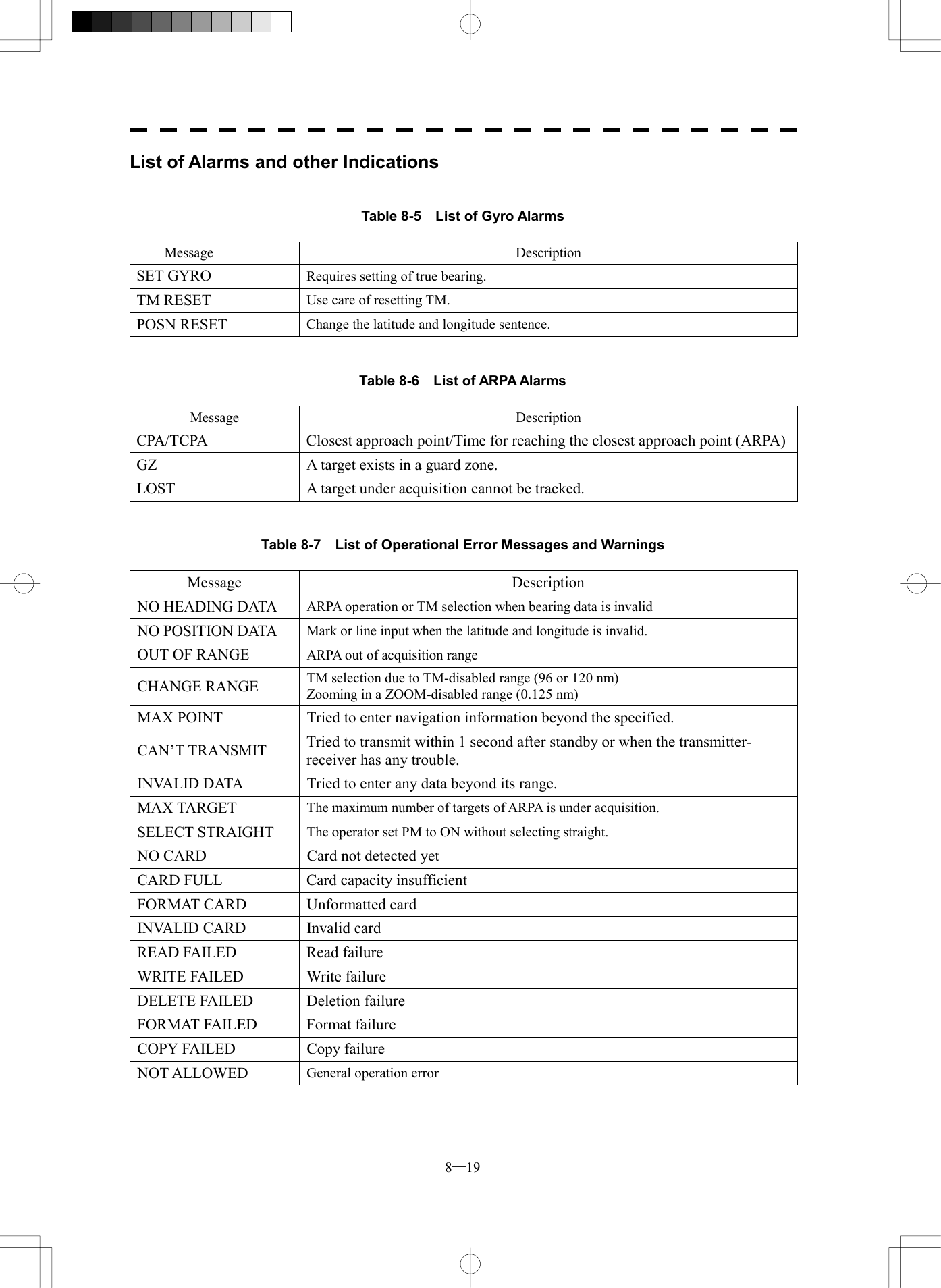
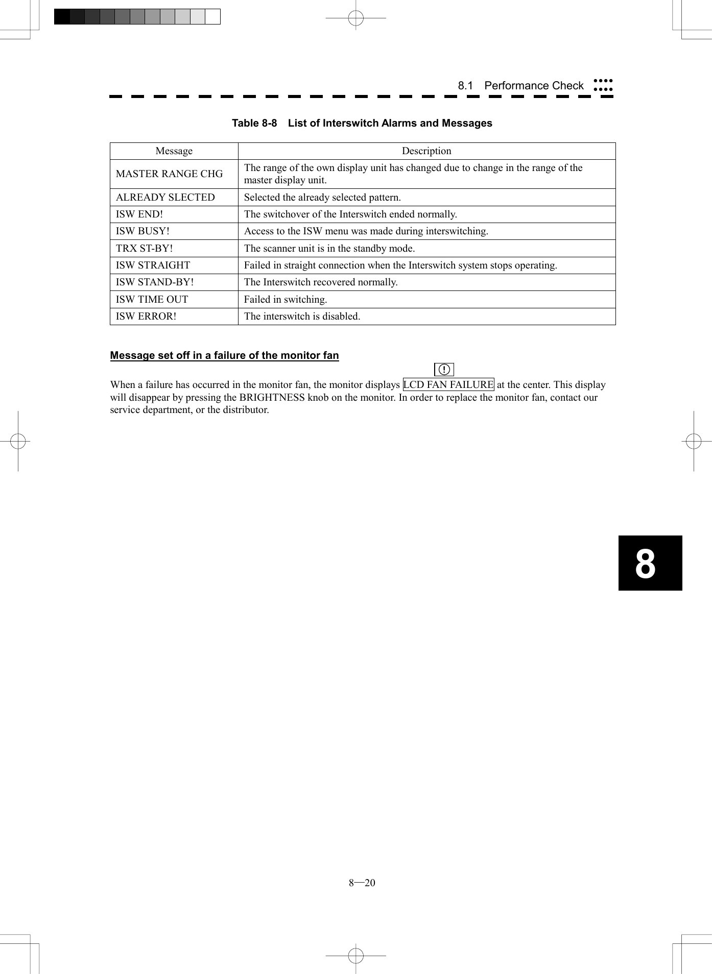
![8─2 88.1 Performance Check Test Menu1. Self Test2. Monitor Test3. Keyboard Test4. PM DisplayON5. Error Logging6. System INFO 0. EXIT MAGI Check Performance on Test Menu The performance status of this radar equipment can be checked on the TEST Menu. Self Test [I] Self-diagnostic function Monitor Test [II] Monitor check Keyboard Test [III] Operation panel check PM Display [IV] Performance monitor Error Logging [V] Error log display System INFO [VI] System information display MAGI [VII] Indication of magnetron current * Execution of PM Display requires a PM unit. Procedures 1 Press [RADAR MENU] key twice. Press [8] key. Press [9] key. The TEST Menu will appear. * Button 57 on the radar display on page 2-7 is also available. 2 Select the check item you want to check, pressing the numeric keys [1] to [6] on Test Menu. The list of check items will appear. Exit 1 Press [RADAR MENU] key. The TEST Menu will be closed.](https://usermanual.wiki/Japan-Radio/NKE2252.Instruction-manual-2-of-3/User-Guide-482879-Page-103.png)
![8─3 Self Test1. Memory Test2. Sensor Test3. Line Test 0. EXIT [I] Self-diagnosis function Check of Memory, Scanner Unit, and Communications Lines Memory Test 1) Memory check Sensor Test 2) Antenna check Line Test 3) Communication line check Procedures 1 Press [1] key while the Test Menu is open. The SELF TEST Menu will appear. 2 Select the item you want to check, pressing numeric keys [1] to [3] . The SELF CHECK Menu will appear. Exit 1 Press [RADAR MENU] key. The Self Test Menu will be closed.](https://usermanual.wiki/Japan-Radio/NKE2252.Instruction-manual-2-of-3/User-Guide-482879-Page-104.png)
![8─4 88.1 Performance Check Memory Test1. SDRAMOK2. SRAMOK3. FLASH ROMOK4. GRAPHICOK 0. EXIT 1) Memory Test Checks for the performance of built-in memory. SDRAM SDRAM check SRAM SRAM check FLASH ROM Flash ROM check GRAPHIC Graphic check Procedures 1 Press [1] key while the Self Test menu is open. The Memory Test Menu will appear. 2 Select the item you want to check, pressing numeric keys [1] to [4]. When no abnormality is found, OK is displayed. When an abnormality is found, NG is displayed. Exit 1 Press [RADAR MENU] key. The menu will be closed.](https://usermanual.wiki/Japan-Radio/NKE2252.Instruction-manual-2-of-3/User-Guide-482879-Page-105.png)
![8─5 Sensor TestOK※ Safety Switch 0. EXIT OK※ AZI PulseOK※ HL PulseOK※ MH CurrentOK※ TriggerOK※ Video 2) Sensor Test Checks for signals from the antenna. Safety Switch Antenna’s safety switch check AZI Pulse Antenna rotation signal check HL Pulse Heading line signal check MH Current Check on the load current of high voltage in the modulator Trigger Radar trigger signal check Video Radar video check Procedures 1 Press [2] key while the Self Test menu is open. The Sensor Test menu will appear. When no abnormality is found, OK is displayed. When an abnormality is found, NG is displayed. In standby, ** will appear. Exit 1 Press [RADAR MENU] key. The menu will be closed.](https://usermanual.wiki/Japan-Radio/NKE2252.Instruction-manual-2-of-3/User-Guide-482879-Page-106.png)
![8─6 88.1 Performance Check 3) Check of Communication Lines Check the status of communications with options. MTR Check on connection with the transmitter-receiver SIG.PROC Check on connection with the signal processing circuit ATA Check on connection with the ARPA processing circuit NSK Check on connection with the NSK unit GPS Compass Check on connection with the GPS compass ISW Check on connection with the interswitch COM1 Check on connection with COM1 COM2 Check on connection with COM2 COM3 Check on connection with COM3 COM4 Check on connection with COM4 Procedures 1 Press [3] key with the Self Test menu open. The Line Test menu will appear. When no abnormality is found, OK is displayed. When an abnormality is found, NG is displayed. The status display field of equipment not connected is left blank. Exit 1 Press [RADAR MENU] key. The menu will be closed. Line TestOK※ MTR 0. EXITOK※ SIG.PROCOK※ ATA OK※ NSKOK※ GPS CompassOK※ ISWOK※ COM1OK※ COM2OK※ COM3OK※ COM4](https://usermanual.wiki/Japan-Radio/NKE2252.Instruction-manual-2-of-3/User-Guide-482879-Page-107.png)
![8─7 Monitor Test1. Pattern 12. Pattern 23. Pattern 34. Pattern 45. Pattern 5 0. EXIT [II] Monitor Test Checks for the monitor. Procedures 1 Press [2] key while the Test Menu is open. The Monitor Test Menu will appear. 2 Select the item number you want to display, pressing numeric keys [1] to [5] of the test pattern. The selected test pattern will be displayed. Pattern 1: All colors are filled with white. Pattern 2: A white box is displayed on the black background of 1280 ´ 1024 dots. Pattern 3: Displays rectangle ´ 2, circle ´ 2, and cross-shape´ 13 (white lines on the black background). Pattern 4: Displays “H” of 9 dots ´ 9 dots on the entire screen (white character on the black background). Pattern 5: Gray scale display (16 levels) Pattern 6: Displays a color bar. 3 To return to the original display, press any key. If errors occur in the monitor, no test pattern will appear. Exit 1 Press [RADAR MENU] key. The menu will be closed.](https://usermanual.wiki/Japan-Radio/NKE2252.Instruction-manual-2-of-3/User-Guide-482879-Page-108.png)
![8─8 88.1 Performance Check Keyboard Test1. Key Test2. Buzzer Test3. Light 0. EXIT[III] Operation Panel Test Checks for the controls and switches of the operation panel. Key Test 1) Key check Buzzer Test 2) Buzzer check Light 3) Keyboard light check Procedures 1 Press [3] key while the Test Menu is open. The Keyboard Test Menu will appear. 2 Select the item number you want to check, pressing numeric keys [1] to [3] of the item. The check contents will be displayed. Exit 1 Press [RADAR MENU] key. The menu will be closed.](https://usermanual.wiki/Japan-Radio/NKE2252.Instruction-manual-2-of-3/User-Guide-482879-Page-109.png)
![8─9 1) Key Check Checks for the controls and switches of the operation panel. Procedures 1 Press [1] key while the Keyboard Test menu is open. The operation panel image will appear at the upper left of the display. Each key on the operation panel on the display is shown in reverse video at the same time the key is pressed, and the name of the pressed key is displayed. 2 To return to the normal display, move the cursor onto “EXIT” on the left side of the display, and press [ENT] key. Exit 1 Press [0] key. The menu will be closed. Keyboard Test1. Key Test2. Buzzer Test3. Light 0. EXIT](https://usermanual.wiki/Japan-Radio/NKE2252.Instruction-manual-2-of-3/User-Guide-482879-Page-110.png)
![8─10 88.1 Performance Check Keyboard Test1. Key Test2. Buzzer Test3. Light 0. EXIT2) Buzzer Test Checks for the operation panel buzzer. Procedures 1 Press [2] key while the Keyboard Test menu is open. The buzzer will sound. 2 The buzzer will sound for a given length of time. Exit 1 Press [RADAR MENU] key. The menu will be closed.](https://usermanual.wiki/Japan-Radio/NKE2252.Instruction-manual-2-of-3/User-Guide-482879-Page-111.png)
![8─11 3) Light Checks for the operation panel light. Procedures 1 Press [3] key while the Keyboard Test menu is open. The brightness of the operation panel is gradually intensified at four levels. Exit 1 Press [RADAR MENU] key. The menu will be closed. Keyboard Test1. Key Test2. Buzzer Test3. Light 0. EXIT](https://usermanual.wiki/Japan-Radio/NKE2252.Instruction-manual-2-of-3/User-Guide-482879-Page-112.png)
![8─12 88.1 Performance Check Test Menu1. Self Test2. Monitor Test3. Keyboard Test4. PM DisplayON5. Error Logging6. System INFO 0. EXITMAGIPM [IV] PM Display Displays the bar indicating the performance monitor status. * Execution of this item needs a PM unit. Procedures 1 Press [4] key while the Test Menu is open, and set PM Display to ON. The PM bar will appear under the MAGI bar. The setting of PM Display is switched back and forth between ON and OFF each time [4] is pressed. Exit 1 Press [RADAR MENU] key. The menu will be closed.](https://usermanual.wiki/Japan-Radio/NKE2252.Instruction-manual-2-of-3/User-Guide-482879-Page-113.png)
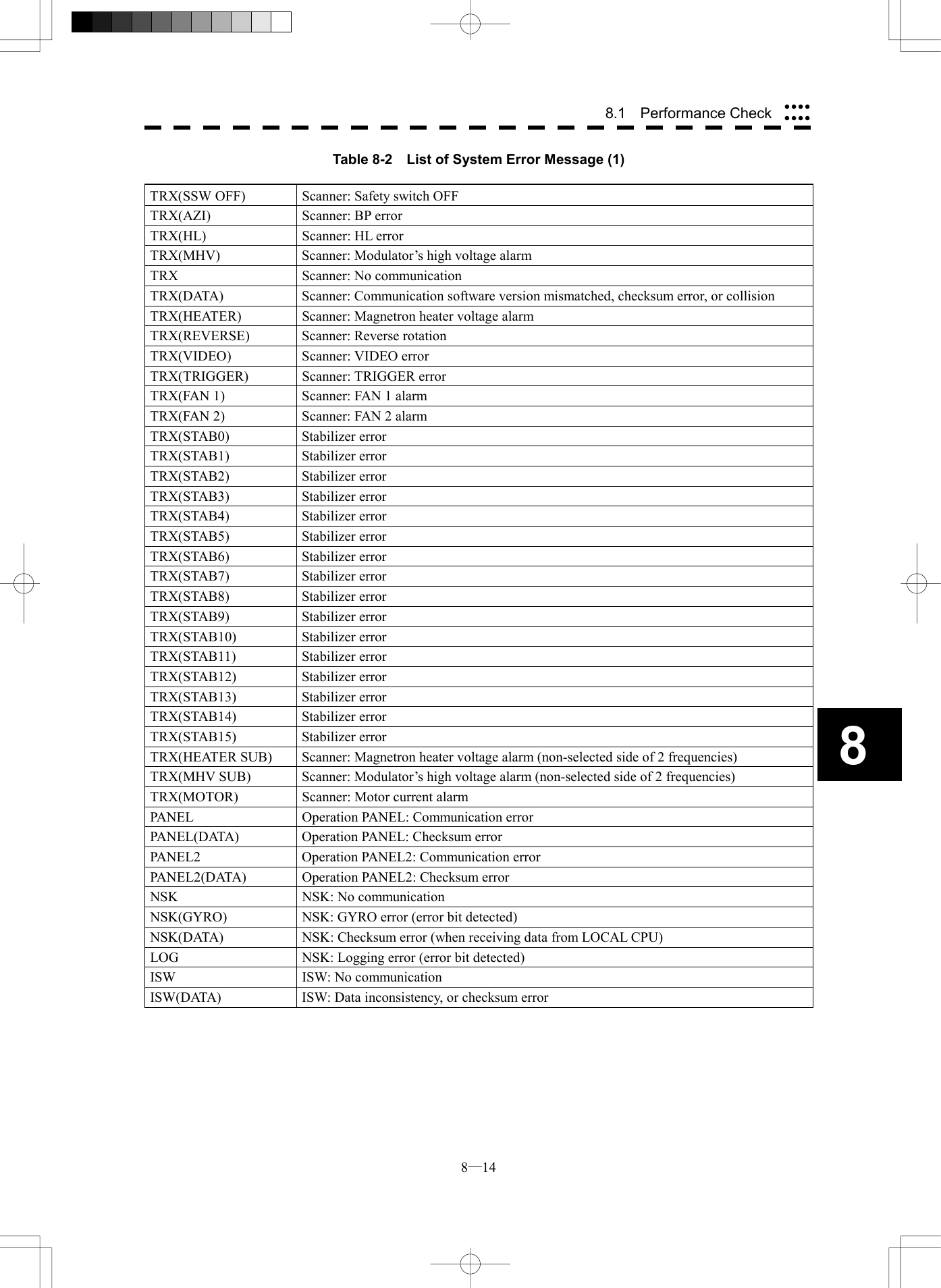
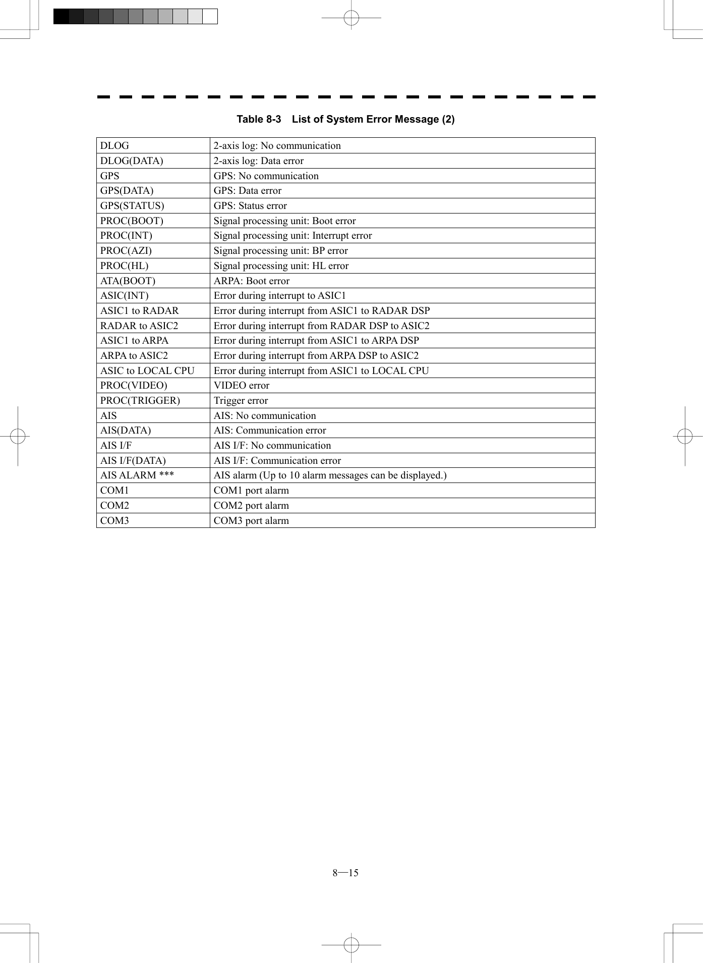
![8─13 Error Logging 0. EXIT 1. All Clear[V] Error Logging When a system error occurs, this function shows the error communication line in reverse video. Errors that have been reset are also displayed in time series. Procedures 1 Press [5] key while the Test Menu is open. The Error Logging Menu will appear. 2 Error logs will be displayed in the dotted area in the figure at right. For the display contents, refer to Table 8-2. Press [1] key to clear all the error logs. Exit 1 Press [RADAR MENU] key. The menu will be closed.](https://usermanual.wiki/Japan-Radio/NKE2252.Instruction-manual-2-of-3/User-Guide-482879-Page-114.png)
![8─17 System INFO※ Indicator Ver.xx.xx EXIT※ MTR Ver.xx.xx※ System No. No. xxxxx※TX TIME Xx hoursX-BANDXx hoursS-BAND※ Total Time Xx hours[VI] System INFO Displays the current system information. Indicator Processor software version information MTR Scanner software version information System No. System number TX Time Total transmitting time (Total time during which radar was transmitted) Tot al Ti me Total operating time (Total power-on time) Procedures 1 Press [6] key while the Test Menu is open. The System INFO Menu will appear. Exit 1 Press [RADAR MENU] key. The menu will be closed.](https://usermanual.wiki/Japan-Radio/NKE2252.Instruction-manual-2-of-3/User-Guide-482879-Page-118.png)
![8─18 88.1 Performance Check Test Menu1. Self Test2. Monitor Test3. Keyboard Test4. PM DisplayON5. Error Logging6. System INFO 0. EXITMAGI [VII] MAGI Displays the MAGI bar indicating the magnetron current to check. Procedures 1 Check if the MAGI bar in the Test Menu reads the value below in a range of 24 NM. 10 kW: 4 to 5 scale marks 25 kW: 5 to 8 scale marks Exit 1 Press [RADAR MENU] key. The menu will be closed.](https://usermanual.wiki/Japan-Radio/NKE2252.Instruction-manual-2-of-3/User-Guide-482879-Page-119.png)
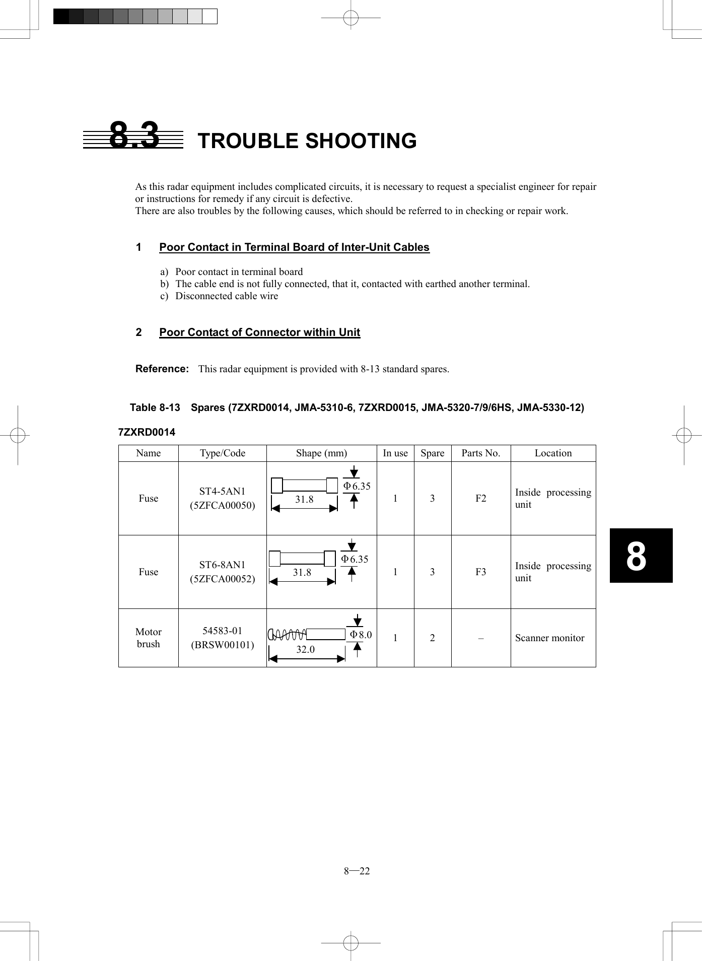
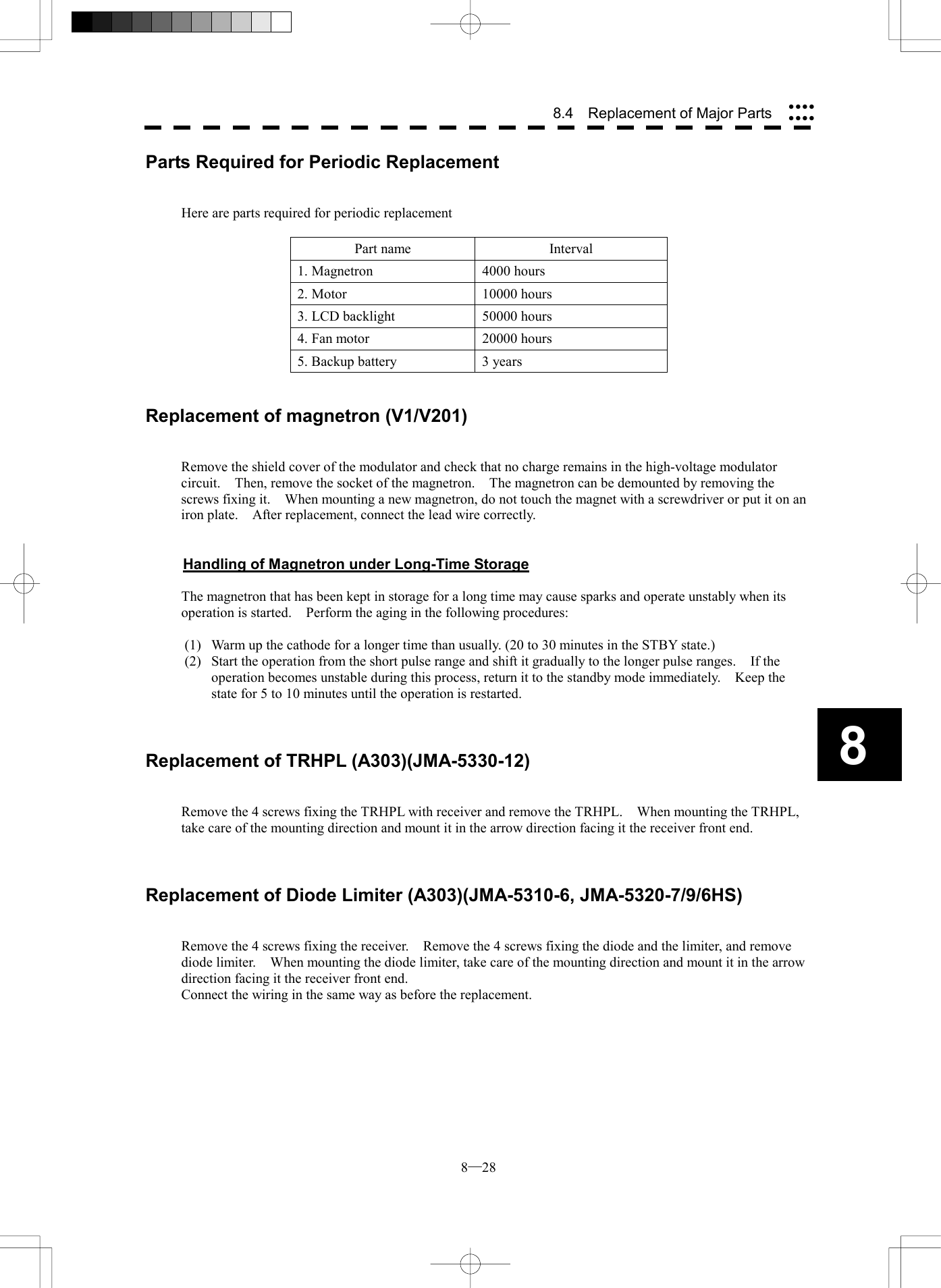
![8─23 7ZXRD0015 Name Type/Code Shape (mm) In use Spare Parts No. Location Fuse ST6-10AN1 (5ZFCA00053) 1 3 F2 Inside processing unit Fuse ST6-10AN1 (5ZFCA00053) 1 3 F3 Inside processing unit Table 8-14 Special Parts [I] JMA-5310-6 Parts No. Name Type Manufacturer Location Code V101 Magnetron MSF1425B NJRC Scanner 5VMAA00051 A101 Circulator FCX68 Toshiba Scanner 6AJRD00001 A102 Diode Limiter NJS6930 NJRC Scanner 5EZAA00024 [II] JMA-5320-7/9/6HS Parts No. Name Type Manufacturer Location Code V1 Magnetron M1568B(J) NJRC Scanner 5VMAA00082 A101/A102 Circulator FCX68 Toshiba Scanner 6AJRD00001 A303 Diode Limiter NJS6930 NJRC Scanner 5EZAA00024 [III] JMA-5330-12 Parts No. Name Type Manufacturer Location Code V1 Magnetron M1302 NJRC Scanner 5VMAA00032 A101 Circulator NJC3320 NJRC Scanner 5AJBV00004 A303 TRHPL TL378A NJRC Scanner 5VLAA00032 31.8 Φ6.3531.8 Φ6.35](https://usermanual.wiki/Japan-Radio/NKE2252.Instruction-manual-2-of-3/User-Guide-482879-Page-124.png)
![8─30 8Code InputPress “0” and “ENT” to Adjust Menu 1 2 34 5 67 8 9+ 0 -CLRENT8.5 ADJUSTMENTS This section describes the electrical adjustments of the equipment as the adjustment procedures to be carried out by service persons at the time of installation. CAUTION Do not carry out the adjustments of the equipment except authorized service persons. If wrong setting is carried out, this may cause unstable operation. Do not carry out the adjustments during navigation. Otherwise, the radar performance may be affected, resulting in an accident or trouble. Tuning, bearing and range adjustments can be made from the operation panel. Start the adjustment mode in the following procedures. How to open the Adjust Menu Procedures 1 Continue to press [RADAR MENU] key. The Code Input Menu will appear. 2 Press [0] key. 3 Move the cursor onto the “ENT” button in the Code Input menu, and press [ENT] key. The Adjust Menu will appear.](https://usermanual.wiki/Japan-Radio/NKE2252.Instruction-manual-2-of-3/User-Guide-482879-Page-131.png)
![8─31 4 Press [1] key. The Equipment Setup Menu will appear. Exit 1 Press [RADAR MENU] key. The Main Menu will reappear. Adjust Menu1. Equipment Setup2. Maintenance Menu9. SP/ATA INIT Setup0. EXITEquipment Setup1. Bearing Adjustment0.0°2. Range Adjustment000. EXIT 3. Tune Adjustment4. TRX Setting5. COM Port Setting6. NAV Setting7. Sector Blank9. LanguageENGLISH](https://usermanual.wiki/Japan-Radio/NKE2252.Instruction-manual-2-of-3/User-Guide-482879-Page-132.png)
![8─32 8.5 Adjustments 8Tuning Adjustment Procedures 1 Open the Equipment Setup Menu. 2 Press [3] key. The Code Input Menu will appear. 3 Using numeric pad, enter the value and then press “ENT” button, and press “EXIT” button to determine the value. The multi-function control can also be used to enter the value. 4 Repeat Step 3, and adjust the bar-graph of the tuning indicator on the upper left of the display so that it becomes the longest. Exit 1 Press [RADAR MENU] key. The Main Menu will reappear. Equipment Setup1. Bearing Adjustment0.0°2. Range Adjustment000. EXIT3. Tune Adjustment4. TRX Setting5. COM Port Setting6. NAV Setting7. Sector Blank9. LanguageENGLISH](https://usermanual.wiki/Japan-Radio/NKE2252.Instruction-manual-2-of-3/User-Guide-482879-Page-133.png)
![8─33 Bearing Adjustment Adjust the bearing so that bearing of the target measured with the ship’s compass matches that of the target echo on the radar display. Procedures 1 Press AZI MODE to select the relative bearing presentation [H UP] mode. Set Image Processing to OFF. [AZI MODE] ® Button 5on the Radar Menu Image Processing ® Button 12 in the Radar Menu 2 Measure the bearing of an adequate target (for example, a ship at anchor, a breakwater or a buoy) relative to own ship’s heading. 3 Open the Equipment Setup Menu. 4 Press [1] key. The Code Input Menu will appear. 5 Using numeric key, enter the value and then press “ENT” button, and press “EXIT” button to determine the value. The multi-function control can also be used to enter the value. 6 Repeat Step 5 above, and adjust to display the target measured in Step 2 to the measured bearing. Exit 1 Press [RADAR MENU] key. The Main Menu will reappear. Equipment Setup1. Bearing Adjustment0.0°2. Range Adjustment000. EXIT 3. Tune Adjustment4. TRX Setting5. COM Port Setting6. NAV Setting7. Sector Blank9. LanguageENGLISH](https://usermanual.wiki/Japan-Radio/NKE2252.Instruction-manual-2-of-3/User-Guide-482879-Page-134.png)
![8─34 8.5 Adjustments 8Range Adjustment Adjust the range so that the range of the target on the radar video is indicated correctly. Procedures 1 Search the radar display for a target of which range is already known. 2 Open the Equipment Setup Menu. 3 Press [2] key. The Code Input Menu will appear. 4 Using numeric pad, enter the value and then press “ENT” button, and press “EXIT” button to determine the value. The multi-function control can also be used to enter the value. 5 Repeat step 4, and adjust until the target range measured in step 1 and the range on the radar display become identical. Exit 1 Press [RADAR MENU] key. The Main Menu will reappear. Equipment Setup1. Bearing Adjustment0.0°2. Range Adjustment000. EXIT3. Tune Adjustment4. TRX Setting5. COM Port Setting6. NAV Setting7. Sector Blank9. LanguageENGLISH](https://usermanual.wiki/Japan-Radio/NKE2252.Instruction-manual-2-of-3/User-Guide-482879-Page-135.png)
![8─35 Antenna Height Adjustment Set the antenna height above the sea level, but change this setting carelessly. Procedures 1 Measure the height from the sea level to the antenna in advance. 2 Open the Equipment Setup Menu. 3 Press [4] key. The TRX Setting Menu will appear. 4 Press [1] key. The Antenna Height Set Value window will appear. 5 Select the antenna height measured in step 1 from the pull-down menu by pressing the numeric key [1] to [4]. The antenna height will be determined. Exit 1 Press [RADAR MENU] key. The Main Menu will reappear. TRX Setting1. Antenna Height5-10m8. Antenna Location04. PM Adjustment20487. Output Pulse0m 0m0. EXIT](https://usermanual.wiki/Japan-Radio/NKE2252.Instruction-manual-2-of-3/User-Guide-482879-Page-136.png)
![8─36 8.5 Adjustments 8Bearing Pulse Output Adjustment (Output Pulse) Set the output value of bearing pulse. This radar can set the output value to 2048 pulses and 4096 pulses. This setting is allowed only when a 25 kw antenna is used. Procedures 1 Open the Equipment Setup Menu. 2 Press [4] key. The TRX Setting Menu will appear. 3 Press [7] key. 4 Select a set value to be used. Exit 1 Press [RADAR MENU] key. The Main Menu will reappear. TRX Setting1. Antenna Height5-10m0. EXIT04. PM Adjustment0 7. Output Pulse2048 8. Antenna Location0m 0m](https://usermanual.wiki/Japan-Radio/NKE2252.Instruction-manual-2-of-3/User-Guide-482879-Page-137.png)
![8─37 Scanner Antenna Location Adjustment (Antenna Location) Set the position at which the scanner is installed. Procedures 1 Open the Equipment Setup Menu. 3 Press [4] key. The TRX Setting Menu will appear. 4 Press [8] key. The Antenna Location Menu will appear. TRX Setting1. Antenna Height5-10m0. EXIT 04. PM Adjustment7. Output Pulse2048 8. Antenna Location0m 0m](https://usermanual.wiki/Japan-Radio/NKE2252.Instruction-manual-2-of-3/User-Guide-482879-Page-138.png)
![8─38 8.5 Adjustments 8 5 Enter two values, a and b. With a > 0, the antenna is installed in the ship’s heading direction. With a < 0, the antenna is installed in the ship’s stem direction. With b > 0, the antenna is installed in the ship’s starboard side direction. With b < 0, the antenna is to be installed in the ship’s port side direction. Pressing T, LT, L, LB, B, RB, R, or RT in the own ship gives ±sign, appropriate to the place, to values a and b. Press CLR for cancellation. Press ENT to determine the value. 6 Press [0] key. Entry will end. Exit 1 Press [RADAR MENU] key. The Main Menu will reappear. b aa: 35mb: -5m4 5 61 2 37 8 9- 0+CLRENT(-500 to 500 [m])Antenna Location1. SET 0. EXIT Set Location RoughlyTLTLLBBRTRRB](https://usermanual.wiki/Japan-Radio/NKE2252.Instruction-manual-2-of-3/User-Guide-482879-Page-139.png)
![8─39 Baud Rate1. COM1 (GPS)4800bps2. COM2 (PC)4800bps384000bp0. EXIT 3. COM3 (NAV1)4800bps4. COM4 (NAV2)5. COM5 (COMPASS)4800bps 1. 1200bps2. 4800bps3. 38400bpsCOM Port Setting External sensor signals are to be entered to this radar via a COM port. This radar has five COM ports. Input of signals from sensors or output of signals to sensors needs to adjust the COM port in accordance with the sensors. [I] Baud Rate Setting Set the baud rate of the signal to be entered into the COM port. Procedures 1 Open the Equipment Setup Menu. 2 Press [5] key. The COM Port Setting Menu will appear. 3 Press [1] key. The Baud Rate Setting Menu will appear. 4 Select the port number you want to set, pressing the numeric keys [1] to [5]. The Baud Rate Selection menu will appear. 5 In the selection menu, select the baud rate you want to set, pressing the numeric key. Selection value 1. COM1 (GPS): 1200/4800/*38400 bps 2. COM2 (PC): 1200/4800/ 38400/115200 bps 3. COM3 (NAV1): 1200/4800/38400 bps 4. COM4 (NAV2): 1200/4800/*38400 bps 5. COM5 (COMPASS): 4800/38400 bps * If COM1/COM4 is set to 38400 bps, signals can only be transmitted. The baud rate for reception can be set to up to 4800 bps. COM5 can be used for receive port only. It is dedicated for COMPASS signal. This means that the port is unavailable for other signals. The GPS, PC, NAV1, NAV2, COMPASS in the parentheses are the standard ports connecting to the external sensors. Exit 1 Press [RADAR MENU] key. The Main Menu will reappear.](https://usermanual.wiki/Japan-Radio/NKE2252.Instruction-manual-2-of-3/User-Guide-482879-Page-140.png)
![8─40 8.5 Adjustments 8GPS (LL/COG/SOG) 1. GGAUSE2. RMCUSEUSE0. EXIT3. RMAUSE4. GNS5. GLL6. VTGUSEUSE[II] Reception Sentence Setting (RX Sentence) Set signal sentences to be received from sensors. Procedures 1 Open the Equipment Setup Menu. 2 Press [5] key. The COM Port Setting Menu will appear. 3 Press [2] key. The RX Sentence Menu will appear. 4 Select the signal you want to set, pressing the numeric keys [1] to [3]. The Setting Menu for each signal will appear. Settable signal 1. GPS (LL/COG/SOG) 2. GPS (WPT/Time) 3. Depth 4. Wind 5. Current ¯ ¯ 5 Select whether or not you want to use sentence for the signal. Types of sentences to be used GPS (LL/COG/SOG): GGA/RMC/RMA/GNS/ GLL/VTG GPS (WPT/Time): GGA/RMC/RMB/ BWC/BWR/ZDA Depth: DPT/DBK/DBT/DBS Wind: MWV/MWD Current: CUR After having selected a signal, choose the number of the sentence for which you want to set whether or not it is used, pressing the numeric key. As concerns current, set data set number and layer number of CUR sentence. Exit 1 Press [RADAR MENU] key. The Main Menu will reappear. RX Sentence 1. GPS (LL/COG/SOG) >2. GPS (WPT/Time) >0. EXIT3. Depth > 5. Current >4. Wind >](https://usermanual.wiki/Japan-Radio/NKE2252.Instruction-manual-2-of-3/User-Guide-482879-Page-141.png)
![8─41 [III] Transmission Port Setting (TX Port) Set the number of the port via which signals are transmitted to sensors. Procedures 1 Open the Equipment Setup Menu. 2 Press [5] key. The COM Port Setting Menu will appear. 3 Press [3] key. The TX Port Menu will appear. 4 Select the signal you want to set, pressing the numeric keys [1] to [8]. The Output Port Setting Menu for each signal will appear. Settable signals 1. TTM (ATA Target) 2. TLL (ATA Target) 3. OSD 4. RSD 5. ALR 6. AIS 7. TTM (AIS Target) 8. TLL (AIS Target) 5 Select which port you want to use for output. Types of ports to be used 1. OFF 2. COM1 (GPS) 3. COM2 (PC) 4. COM3 (NAV1) 5. COM4 (NAV2) Select the number of the port to be used, pressing the numeric key. Exit 1 Press [RADAR MENU] key. The Main Menu will reappear. * Note that, if you set COM1 and COM4 for transmission, they cannot be used as reception ports. TX Port1. TTM (ATA Target)2. TLL(ATA Target) 0. EXIT 3. OSD OFFOFFOFFOFFOFFAUTO4. RSD 5. ALR 6. AIS OFF7. TTM (AIS Target)OFF8. TTL (AIS Target)1. OFF2. COM1 (GPS)3. COM2 (PC)4. COM3 (NAV1)5. COM4 (NAV2)](https://usermanual.wiki/Japan-Radio/NKE2252.Instruction-manual-2-of-3/User-Guide-482879-Page-142.png)
![8─42 8.5 Adjustments 8RX Port1. GPS 2. DLOG0. EXIT3. Depth AUTOAUTOOFFAUTOAUTOAUTO4. Temperature5. Wind6. Current 1.AUTO2. COM1 (GPS)3. COM2 (PC)4. COM3 (NAV1)5. COM4 (NAV2)[IV] Reception Port Setting (RX Port) Set the number of the port via which signals are received from sensors. Procedures 1 Open the Equipment Setup Menu. 2 Press [5] key. The COM Port Setting Menu will appear. 3 Press [4] key. The RX Port Menu will appear. 4 Select the signal you want to set, pressing the numeric keys [1] to [6]. The Reception Port Setting Menu for each signal will appear. Settable signals 1. GPS 2. DLOG 3. Depth 4. Temperature 5. Wind 6. Current 5 Select which port you want to use for output. Types of ports to be used 1. AUTO 2. COM1 (GPS) 3. COM2 (PC) 4. COM3 (NAV1) 5. COM4 (NAV2) * For AUTO, the initial value will be selected. Select the number of the port to be used, pressing the numeric key. Exit 1 Press [RADAR MENU] key. The Main Menu will reappear.](https://usermanual.wiki/Japan-Radio/NKE2252.Instruction-manual-2-of-3/User-Guide-482879-Page-143.png)
![8─43 NAV Setting1. Sel NAV EquipmentINT GPS2. GPS ANT. Location0. EXIT 0m 0mNavigator Setting (NAV Setting) JRC’s GPS adopts connector connections on the backside of the processing unit. However, a GPS produced by other manufacturers uses terminal strip inputs in the processing unit. To do so, input area settings are needed. In addition, GPS antenna installation position can be set. [1] Navigator Setting (Sel NAL Equipment) Set whether the navigator to be connected is to be installed inside (JRC’s GPS) or outside (other manufacturer’s GPS). Procedures 1 Open the Equipment Setup Menu. 2 Press [6] key. The NAV Setting Menu will appear. 3 Press [1] key. Switching between inside and outside is done each time the key is pressed. INT GPS: JRC’s GPS (connection on the backside of the processing unit) EXT: Other manufacturer’s GPS (Terminal strip connection inside the processing unit) Exit 1 Press [RADAR MENU] key. The Main Menu will reappear.](https://usermanual.wiki/Japan-Radio/NKE2252.Instruction-manual-2-of-3/User-Guide-482879-Page-144.png)
![8─44 8.5 Adjustments 8NAV Setting1. Sel NAV EquipmentINT GPS2. GPS ANT. Location0. EXIT 0m 0m[II] GPS Antenna Location Setting (GPS ANT. Location) Set the GPS antenna installation position. Procedures 1 Open the Equipment Setup Menu. 2 Press [6] key. The NAV Setting Menu will appear. 3 Press [2] key. The GPS Antenna Location Menu will appear.](https://usermanual.wiki/Japan-Radio/NKE2252.Instruction-manual-2-of-3/User-Guide-482879-Page-145.png)
![8─45 5 Enter two values, a and b. With a > 0, GPS antenna is installed in the ship’s heading direction. With a < 0, GPS antenna is installed in the ship’s stem direction. With b > 0, GPS antenna is installed in the ship’s starboard side direction. With b < 0, GPS antenna is to be installed in the ship’s port side direction. Pressing T, LT, L, LB, B, RB, R, or RT in the own ship gives ±sign, appropriate to the place, to values a and b. Press CLR for cancellation. Press ENT to determine the value. 6 Press [0] key. Entry will end. Exit 1 Press [RADAR MENU] key. The Main Menu will reappear. baa: 35mb: -5m4 5 61 2 37 8 9- 0+CLR ENT(-500 to 500 [m])Antenna Location1. SET 0. EXIT Set Location RoughlyTLTLLBBRTRRB](https://usermanual.wiki/Japan-Radio/NKE2252.Instruction-manual-2-of-3/User-Guide-482879-Page-146.png)
![8─46 8.5 Adjustments 8Sector Blank1. Sector 1ON2. Sector2ONON0. EXIT3. Sector34. Make Sector 15. Make Sector 26. Make Sector 37. ENT Sector Blank Function (Sector Blank) Set a sector range, preventing displaying the radar echo only within the area. Three types of sector can be created. [I] Turning ON/OFF the Sector function (Sector 1, 2 and 3) Procedures 1 Open the Equipment Setup Menu. 2 Press [7] key. The Sector Blank Menu will appear. 3 Select the number you want to excuted sector blank, Pressing the numeric keys [1] to [3]. Switching between ON and OFF is done each time the key is pressed. ON: Execution of sector blank OFF: Cancel Exit 1 Press [RADAR MENU] key. The Main Menu will reappear. Note: This function can be performed only when the scanner is connected to NKE-2252 and 1075A.](https://usermanual.wiki/Japan-Radio/NKE2252.Instruction-manual-2-of-3/User-Guide-482879-Page-147.png)
![8─47 Sector Blank1. Sector 1ON2. Sector2ONON0. EXIT 3. Sector34. Make Sector 15. Make Sector 26. Make Sector 3 7. ENT [II] Making Sector Function (Make Sector 1, 2, 3) Procedures 1 Open the Equipment Setup Menu. 2 Press [7] key. The Sector Blank Menu will appear. 3 Slect the number you want to make sector blank, pressing the numeric keys [4] to [6]. The sector blank for the numeric key pressed will be made. 4 Set the start point of the sector blank by operating the [EBL] dial, and then press ENT. The start angle of the sector blank will be set. 5 Set the end point of the sector blank by operating the [EBL] dial, and then press ENT. The end angle of the sector blank will be set. Exit 1 Press [RADAR MENU] key. The Main Menu will reappear.](https://usermanual.wiki/Japan-Radio/NKE2252.Instruction-manual-2-of-3/User-Guide-482879-Page-148.png)
![8─48 8.5 Adjustments 8Baud Rate1. Bearing Adjustment0.0°2. Range Adjustment503320. EXIT3. Tune Adjustment4. TRX Setting >5. COM Port Setting >ENGLISH6. Nav Setting > 7. Sector Blank >9. Language 1. ENGLISH2. JAPANESE3. OTHERLanguage Setting (Language) You can switch between Japanese and English. Procedures 1 Open the Equipment Setup Menu. 2 Press [9]. The Language Selection window will appear. 3 Select the language you want to display, pressing the numeric keys [1] to [3]. 1. English 2. Japanese 3. Other “Other” in 3. is a language corresponding to characters created in overseas agents. To confirm whether or not your language is supported, contact overseas agents or our sales department. To make the set language effective, turn off the power supply and then restart. Exit 1 Press [RADAR MENU] key. The Main Menu will reappear.](https://usermanual.wiki/Japan-Radio/NKE2252.Instruction-manual-2-of-3/User-Guide-482879-Page-149.png)
![8─49 Maintenance Menu1. Safety SwitchSTANDBY2. Partial Master Reset0. EXIT 3. All Master Reset4. Internal To Card25. Card2 To Internal Maintenance Menu This item is provided for equipment maintenance, including settings of antenna safety switch, master reset, etc. CAUTION Only our service engineers are to make the adjustment. Neglecting this caution may cause accidents and failures. Do not make the adjustments during navigation. Otherwise, adjustments may affect the radar functions, causing accidents and failures. [1] Scanner Safety Switch Setting (Safety Switch) Procedures 1 Open the Adjust Menu. 2 Press [2] key. The Maintenance Menu will appear. 3 Press [1] key. Setting items for the scanner safety switch will appear. 4 Select the item you want to set, pressing the numeric key [1] to [4]. 1. TX OFF: Stops transmission. (The screen remains in the transmission status.) 2. STANDBY: Stops transmission. (The screen switches to the standby status) 3. TX-ON: Continues transmission without changes. (However, errors in bearing signals etc. are to occur due to safety switch-off.) 4. IGNORE ERROR: Continues transmission without changes.(Errors in bearing signals etc. due to safety switch-off are also ignored.) Exit 1 Press [RADAR MENU] key. The Main Menu will reappear.](https://usermanual.wiki/Japan-Radio/NKE2252.Instruction-manual-2-of-3/User-Guide-482879-Page-150.png)
![8─50 8.5 Adjustments 8Maintenance Menu1. Safety SwitchSTANDBY2. Partial Master Reset0. EXIT3. All Master Reset4. Internal To Card25. Card2 To Internal [II] Partial Master Reset Procedures 1 Open the Maintenance Menu. 2 Press [2] key. The Partial Master Reset Execution Check window will appear. 1 YES: Execution of Partial Master Reset 2 NO: Cancellation Partial Master Reset resets items except for those set in the initialization menu. Exit 1 Press [RADAR MENU] key. The Main Menu will reappear.](https://usermanual.wiki/Japan-Radio/NKE2252.Instruction-manual-2-of-3/User-Guide-482879-Page-151.png)
![8─51 Maintenance Menu1. Safety SwitchSTANDBY2. Partial Master Reset0. EXIT 3. All Master Reset4. Internal To Card25. Card2 To Internal [III] All Master Reset (All Master Reset) Procedures 1 Open the Maintenance Menu. 2 Press [3] key. The All Master Reset Execution Check window will appear. 1 YES: Execution of All Master Reset 2 NO: Cancellation All Master Reset resets all items. Exit 1 Press [RADAR MENU] key. The Main Menu will reappear.](https://usermanual.wiki/Japan-Radio/NKE2252.Instruction-manual-2-of-3/User-Guide-482879-Page-152.png)
![8─52 8.5 Adjustments 8Maintenance Menu1. Safety SwitchSTANDBY2. Partial Master Reset0. EXIT3. All Master Reset4. Internal To Card25. Card2 To Internal [IV] Copy Internal Settings to Card2 (Internal To Card2) Execution of this item requires a memory flash card (option). Procedures 1 Insert a flash memory card into the CARD slot 2. 2 Open the Maintenance Menu. 3 Press [4] key. The execution check window will open to check whether or not you want to copy the internal settings to Card2. 1 YES: Execution of copy 2 NO: Cancellation Exit 1 Press [RADAR MENU] key. The Main Menu will reappear.](https://usermanual.wiki/Japan-Radio/NKE2252.Instruction-manual-2-of-3/User-Guide-482879-Page-153.png)
![8─53 Maintenance Menu1. Safety SwitchSTANDBY2. Partial Master Reset0. EXIT 3. All Master Reset4. Internal To Card25. Card2 To Internal [V] Read internal settings from Card2. Execution of this item requires a memory flash card (option). Procedures 1 Insert the memory flash card, in which internal settings have been saved, into Card slot 2. 2 Open the Maintenance Menu. 3 Press [5] key. The execution check window will open to check whether or not you want to read the internal settings from Card2. 1 YES: Read 2 NO: Cancellation Exit 1 Press [RADAR MENU] key. The Main Menu will reappear.](https://usermanual.wiki/Japan-Radio/NKE2252.Instruction-manual-2-of-3/User-Guide-482879-Page-154.png)
![8─54 8.5 Adjustments 8Noise Level1. Main140 0. EXIT2. Setting Mode OFFNoise Level Setting (Noise Level) [1] Setting the noise level for signal processing (Main) Procedures 1 When the Adjust Menu appears, press [9] key. The SP/ATA INIT Setup Menu will appear. 2 Press [1] key. The Noise Level Menu will appear. 3 Press [1] key. The Code Input Menu will open to change the noise level value. 4 Change the value to display echo correctly. In addition to the entry on the Code Input menu, the Multi-functional Dial Control is available to change the value. Exit 1 Press [RADAR MENU] key. The Main Menu will reappear.](https://usermanual.wiki/Japan-Radio/NKE2252.Instruction-manual-2-of-3/User-Guide-482879-Page-155.png)
![8─55 [II] Noise Level Adjustment Mode (Setting Mode) Procedures 1 When the Adjust Menu appears, press [9] key. The SP/ATA INIT Setup Menu will appear. 2 Press [1] key. Options for Setting Mode will appear. 3 Press [3] key. Switching between Setting Mode ON and OFF is done each time the key is pressed. Exit 1 Press [RADAR MENU] key. The Main Menu will reappear. Noise Level1. Main 1400. EXIT 2. Setting Mode OFF](https://usermanual.wiki/Japan-Radio/NKE2252.Instruction-manual-2-of-3/User-Guide-482879-Page-156.png)
![8─56 8.5 Adjustments 8ATA1. Vector Const52. Video TD Level1580. EXIT3. Video High Level14. Video Low LevelNARROW5. Gate SizeOFF6. Limit RingVector Constant Procedures 1 Press [9] key while the Adjust Menu is open. The SP/ATA INIT Setup Menu will appear. 2 Press [2] key. The ATA Menu will appear. 3 Press [1] key. The window for setting vector constants will appear. 4 Select the value you want to set, pressing the numeric keys [1] to [8]. Exit 1 Press [RADAR MENU] key. The Main Menu will reappear. l Do not change the set value carelessly. The vector constant shall be set to 5 normally. If thevector constant value is higher, a target’s vector will be better followed up when the target and own ship change their course or speed, but the vector accuracy will be lower on the contrary. Attention](https://usermanual.wiki/Japan-Radio/NKE2252.Instruction-manual-2-of-3/User-Guide-482879-Page-157.png)
![8─57 ATA1. Vector Const52. Video TD Level1580. EXIT 3. Video High Level14. Video Low LevelNARROW5. Gate SizeOFF6. Limit RingVideo TD Level CAUTION Do not change the set quantization level carelessly. If the level deviates from the proper value, the ARPA acquisition and tracking functions will deteriorate. Otherwise, this may cause accidents. The quantization level determines the minimum signal level of the input video to the ARPA target detection circuit. In this test, the value of the quantization level can be set in a range of 1 to 63. If the value is set to a lower level, weak target echoes will be inputted to the ARPA target detection circuit, but much radar noise will also be inputted to the circuit together, and target acquisition and tracking may be disabled. Therefore, it is important to set a value that is 4 or 5 higher than the detected noise level. Procedures 1 Press [9] key while the Adjust Menu is open. The SP/ATA INIT Setup Menu will appear. 2 Press [2] key. The ATA Menu will appear. 3 Press [2] key. The Code Input Menu will appear. 4 Enter the Video TD Level value. The multi-function control can also be used to enter the value. After having entered the value, press ENT. Exit 1 Press [RADAR MENU] key. The Main Menu will reappear.](https://usermanual.wiki/Japan-Radio/NKE2252.Instruction-manual-2-of-3/User-Guide-482879-Page-158.png)
![8─58 8.5 Adjustments 8MBS1. MBS Level02. MBS Area00. EXITMain Bang Suppression Level Adjustment (MBS Level) Main Bang Suppression is adjusted to suppress main bang, a reflection signal from 3D circuit including wave guide tube, that generally appears as a circular image focusing on the center of the radar display. Optimum adjustment allows main bang image to remain lightly on the display. CAUTION Do not change this adjusted level carelessly. Incorrect adjustment may erase targets in point-blank range and cause collision, resulting in death or serious injury. This adjustment is made for settings in the processing circuit of the display unit. Procedures 1 Perform the following operation before setting. · Set the range to 0.125 nm. · Set the radar video enhance function. · Set the correlation processing function to OFF. · Rotate the [AUTO-SEA] control to achieve the strength with which main bang can be judged. · Rotate [AUTO-RAIN] control to the minimum position (counterclockwise fully). · Rotate [GAIN/PL] control to the maximum position (clockwise fully). 2 Display the SP/ATA INIT Setup Menu. 3 Press [3] key. The MBS Menu will appear. 4 Press [1] key. The Code Input Menu will appear. 5 Enter the Main Bung Suppression Level value. Adjust the value to erase the main bang. Exit 1 Press [RADAR MENU] key. The Main Menu will reappear.](https://usermanual.wiki/Japan-Radio/NKE2252.Instruction-manual-2-of-3/User-Guide-482879-Page-159.png)
![8─59 MBS1. MBS Level02. MBS Area00. EXIT Main Bang Suppression Area Adjustment (MBS Area) Adjust the main bang suppression area. CAUTION Do not change this adjusted level carelessly. Incorrect adjustment may erase targets in point-blank range and cause collision, resulting in death or serious injury. Procedures 1 Perform the following operation before setting. · Set the range to 0.125 nm. · Set the radar video enhance function. · Set the correlation processing function to OFF. · Rotate the [AUTO-SEA] control to achieve the strength with which main bang can be judged. · Rotate [AUTO-RAIN] control to the minimum position (counterclockwise fully). · Rotate [GAIN/PL] control to the maximum position (clockwise fully). 2 Display the SP/ATA INIT Setup Menu. 3 Press [3] key. The MBS Menu will appear. 4 Press [1] key. The Code Input Menu will appear. 5 Enter the Main Bung Suppression Level value. Adjust the value to erase the main bang. Exit 1 Press [RADAR MENU] key. The Main Menu will reappear.](https://usermanual.wiki/Japan-Radio/NKE2252.Instruction-manual-2-of-3/User-Guide-482879-Page-160.png)
![8─60 8.5 Adjustments 8Adjustment of NSK Unit to GYRO Compass and Log The NSK Unit of the radar equipment is designed to be compatible with almost all types of gyro compass by switch operation (For the step motor type, 24 VDC to 100 VDC, and for the synchro-motor type, the primary excitation voltage is 50 VAC to 115 VAC). Before power-on operation, the switches S1, S2, S5 and jumper JP1 on the NSK Unit (PC4201) shall be set to the type of gyro compass in use in accordance with the procedures as described below. The gyro select switch on the NSK Unit is set to the gyration ratio of 360X and to be compatible with the synchro type before delivery from factory. Check the type of the gyro compass used in own ship and make settings in the procedures below. (1) Set the switches of the NSK Unit (PC4201) before turning on the radar equipment. · S1: Set it to [OFF]. · S2: There are two types of gyro compasses: a compass of one type outputs a step signal, and the other outputs a synchro signal. Make sure of the type of gyro compass used with the own ship before setting S2. [SYNC] .......................................Synchro signal [STEP].........................................Step signal · S5: Set S5 depending on the type of the gyro compass currently in use, according to the S5 setting table. S5-1: ..................................Set this switch assembly according to the particular type of gyro. [OFF]...........................................Synchro signal [ON] ............................................Step signal S5-2, -3................................Gyration ratio 360X 180X 90X 36X S5-2 OFF OFF ON ON S5-3 OFF ON OFF ON S5-4.....................................Gyration direction [OFF]...........................................Normal (clockwise) [ON] ............................................Reverse (counterclockwise) S5-5.....................................Log type-1 [OFF]...........................................Pulse signal [ON] ............................................Synchro signal S5-6.....................................Not used](https://usermanual.wiki/Japan-Radio/NKE2252.Instruction-manual-2-of-3/User-Guide-482879-Page-161.png)
![8─61 S5-7, -8............................... Log ratio Pulse/NM (pulse signal) 800 400 200 100 Gyration/NM (synchro signal) 360X 180X 90X 36X S5-7 OFF OFF ON ON S5-8 OFF ON OFF ON · S6:Log test. Set it to [NORMAL]. · S7: Normal or BSH(IMO) specifications selection. Set it to [NORMAL]. · Set JP1 according to the particular gyro. [SYNC]....................................... Synchro signal [STEP] ........................................ Step signal (2) Connect the gyro signal and the log signal cables to the NSK Circuit. (PC4201) (3) Set S1 to [ON]. * After power-on operation, the switch S5-4 shall be set to [ON] if the radar video and the indicated value of COURSE (own ship’s true bearing) is reversed. Table 8-17 Gyro and Log Select Switches (S5 Dip Switch) S5 Setting Table 1 2 3 4 5 6 7 8 SYNC 0 STEP 1 360X 0 0 180X 0 1 90X 1 0 36X 1 1 Normal (NOR) 0 GYRO SIG. DIRECTION Reverse (REV) 1 PULSE 0 TYPE SYNCHRO 1 0 800P/360X 0 0 400P/180X 0 1 200P/90X 1 0 LOG SIG. PULSE/NM 100P/30X 1 1](https://usermanual.wiki/Japan-Radio/NKE2252.Instruction-manual-2-of-3/User-Guide-482879-Page-162.png)
![8─62 88.6 SETTING True Bearing Setting (Set GYRO) Adjust the bearing that the bearing angle of the radar is the same as that of the gyro. Procedures 1 Press [RADAR MENU] key twice. The Main Menu will appear. 2 Press [7] key. The NAV Equipment Setting Menu will appear. 3 Press [1] key. The Code Input Menu will appear. 4 Adjust true bearing value. Adjust the bearing that the bearing angle of the radar is the same as that of the gyro. The multi-function control can also be used to enter the value. After having entered the value, press ENT. Exit 1 Press [RADAR MENU] key. The menu will be closed. NAV Equipment Setting1. Set GYRO0.0°2. Heading EquipmentGYROMAN0. EXIT3. Speed Equipment0.0kts4. Manual Speed5. MAG Compass Setting6. Set/Drift Setting7. GPS Setting](https://usermanual.wiki/Japan-Radio/NKE2252.Instruction-manual-2-of-3/User-Guide-482879-Page-163.png)
![8─63 NAV Equipment Setting1. Set GYRO0.0°2. Heading EquipmentGYROMAN0. EXIT 3. Speed Equipment0.0kts4. Manual Speed5. MAG Compass Setting6. Set/Drift Setting7. GPS SettingShip Speed Equipment Setting (Speed Equipment) Procedures 1 Press [RADAR MENU] key twice. The RADAR Menu will appear. 2 Press [7] key. The NAV Equipment Setting Menu will appear. 3 Press [3] key. 4 Select a ship speed sensor from the pull-down menu. Types of selectable speed sensors: 1: Manual 2: Log 3: 2-axis log (NMEA signal: Speed over water) 4: 2-axis log (NMEA signal: Speed over ground) Exit 1 Press [RADAR MENU] key. The menu will be closed. l The manually entered speed is effective only when “MANUAL” is set. l 2-axis log cannot be effective when the sentence VBW of NMEA0183 is not entered. Attention](https://usermanual.wiki/Japan-Radio/NKE2252.Instruction-manual-2-of-3/User-Guide-482879-Page-164.png)
![8─64 88.6 Setting NAV Equipment Setting1. Set GYRO0.0°2. Heading EquipmentGYROMAN0. EXIT3. Speed Equipment0.0kts4. Manual Speed5. MAG Compass Setting6. Set/Drift Setting7. GPS SettingManual Speed Setting (Manual Speed) Procedures 1 Press [RADAR MENU] key twice. 2 Press [7] key. NAV Equipment Setting Menu will appear. 3 Press [4] key. The Code Input menu will appear. 4 Pressing a numeric key, enter the value and select “ENT.” The multi-function control is also available for the entry. Note: The manually entered speed is effective only when “MANUAL” is set.](https://usermanual.wiki/Japan-Radio/NKE2252.Instruction-manual-2-of-3/User-Guide-482879-Page-165.png)
![8─65 MAG Compass Setting1. Heading CorrectionOFF2. Correct Value0.0°E0. EXIT MAG Compass Setting Set the MAG compass. Procedures 1 Press [RADAR MENU] key twice. The Radar Menu will appear. 2 Press [7] key. NAV Equipment Setting Menu will appear. 3 Press [5] key. MAG Compass Setting Menu will appear. 4 Press [1] key. This item is set as to whether or not the heading bearing is to be corrected. Switching between ON and OFF is done each time you press [1] key. 5 Press [2] key. The Code Input Menu will appear. 6 Pressing a numeric key, enter the value. Select “ENT” and then determine the value. The correction direction and angle will be set. On the screen, press “+” to make correction in the eastern direction, and press “-” to make correction in the western direction. Also enter a correction angle, pressing the numeric key. The multi-function control is also available for the entry. To do so, enter the correction direction, press the multi-function control, enter the correction angle, and then set ENT in order. Exit 1 Press [RADAR MENU] key. The menu will be closed.](https://usermanual.wiki/Japan-Radio/NKE2252.Instruction-manual-2-of-3/User-Guide-482879-Page-166.png)
![8─66 88.6 Setting Set/Drift Setting1. CorrectionOFF2. Set 0.0°0.0kts0. EXIT3. DriftCurrent Correction (SET/DRIFT) Setting The current set and drift will be set. Procedures 1 Press [RADAR MENU] key twice. The RADAR Menu will appear. 2 Press [7] key. The NAV Equipment Setting Menu will appear. 3 Press [6] key. The Set/Drift Setting Menu will appear. 4 Press [1] key to enable Correction. The setting of Correction is switched back and forth between ON and OFF each time [1] key is pressed. 5 Press [2] key. The Code Input Menu will appear. 6 Enter the direction of tendency. The direction of tendency will be set. The multi-function control is also available for the entry. After having entered the direction, press ENT. l The manually entered speed is effective only when 1.MANUAL or 2. 1AXIS is set in 2. SELECT SPEED of SETTING1 Menu. Attention](https://usermanual.wiki/Japan-Radio/NKE2252.Instruction-manual-2-of-3/User-Guide-482879-Page-167.png)
![8─67 7 Press [3] key. The Code Input Menu will appear. 8 Enter the speed of tendency. The speed of tendency will be set. The multi-function control is also available for the entry. After having enter the value, press ENT. Exit 1 Press [RADAR MENU] key. The menu will be closed.](https://usermanual.wiki/Japan-Radio/NKE2252.Instruction-manual-2-of-3/User-Guide-482879-Page-168.png)
![8─68 88.6 Setting GPS Process Setting1. Position00’00.000000’00.0000. EXIT00 3. GeodeticNE2. Exclution00 00 00 00 00 00WGS-844. Antenna Height0m5. Fix Mode 2D6. DOP LevelUp to 57. Position AverageLONG8. Master ResetOFF9. Send DataSetting in GPS Receiver (GPS Process Setting) Set an initial value in the GPS receiver (our GPS receiver). [I] Own ship position setting Procedures 1 Press [RADAR MENU] key twice. The Radar Menu will appear. 2 Press [7] key. NAV Equipment Setting Menu will appear. 3 Press [7] key. GPS Setting Menu will appear. 4 Press [1] key. GPS Process Setting Menu will appear. 5 Press [1] key. The Code Input menu will appear. Enter the latitude, press ENT, enter the longitude, and then press ENT in order. The multi-function control is also available to enter the values. 6 After having entered the values, press [9] key, and transmit the setting contents to the GPS receiver. Exit 1 Press [RADAR MENU] key. The Main Menu will reappear.](https://usermanual.wiki/Japan-Radio/NKE2252.Instruction-manual-2-of-3/User-Guide-482879-Page-169.png)
![8─69 GPS Process Setting1. Position00’00.000000’00.0000. EXIT 00 3. GeodeticNE2. Exclution00 00 00 00 00 00WGS-844. Antenna Height0m5. Fix Mode 2D6. DOP LevelUp to 57. Position AverageLONG8. Master ResetOFF9. Send Data[II] Setting of Banned Satellite (Excltion) Procedures 1 Press [RADAR MENU] key twice. The Radar Menu will appear. 2 Press [7] key. NAV Equipment Setting Menu will appear. 3 Press [7] key. GPS Setting Menu will appear. 4 Press [1] key. GPS Process Setting Menu will appear. 5 Press [2] key. The Code Input menu will appear. Enter the number of the banned satellite. The multi-function control is also available to enter the values. 6 After having entered the value, press [9] key, and transmit the setting contents to the GPS receiver. Exit 1 Press [RADAR MENU] key. The Main Menu will reappear.](https://usermanual.wiki/Japan-Radio/NKE2252.Instruction-manual-2-of-3/User-Guide-482879-Page-170.png)
![8─70 88.6 Setting GPS Process Setting1. Position00’00.000000’00.0000. EXIT003. GeodeticNE2. Exclution00 00 00 00 00 00WGS-844. Antenna Height0m5. Fix Mode 2D6. DOP LevelUp to 57. Position AverageLONG8. Master ResetOFF9. Send Data[III] Geodetic System Setting (Geodetic) Set the geodetic system in which the own ship is currently existent. Procedures 1 Press [RADAR MENU] key twice. The Radar Menu will appear. 2 Press [7] key. NAV Equipment Setting Menu will appear. 3 Press [7] key. GPS Setting Menu will appear. 4 Press [1] key. GPS Process Setting Menu will appear. 5 Press [3] key. The Code Input menu will appear. Enter the geodetic system in accordance with the table on the following page. The multi-function control is also available to enter the values. 6 After having entered the values, press [9] key to transmit the setting contents to the GPS receiver. Exit 1 Press [RADAR MENU] key. The Main Menu will reappear.](https://usermanual.wiki/Japan-Radio/NKE2252.Instruction-manual-2-of-3/User-Guide-482879-Page-171.png)
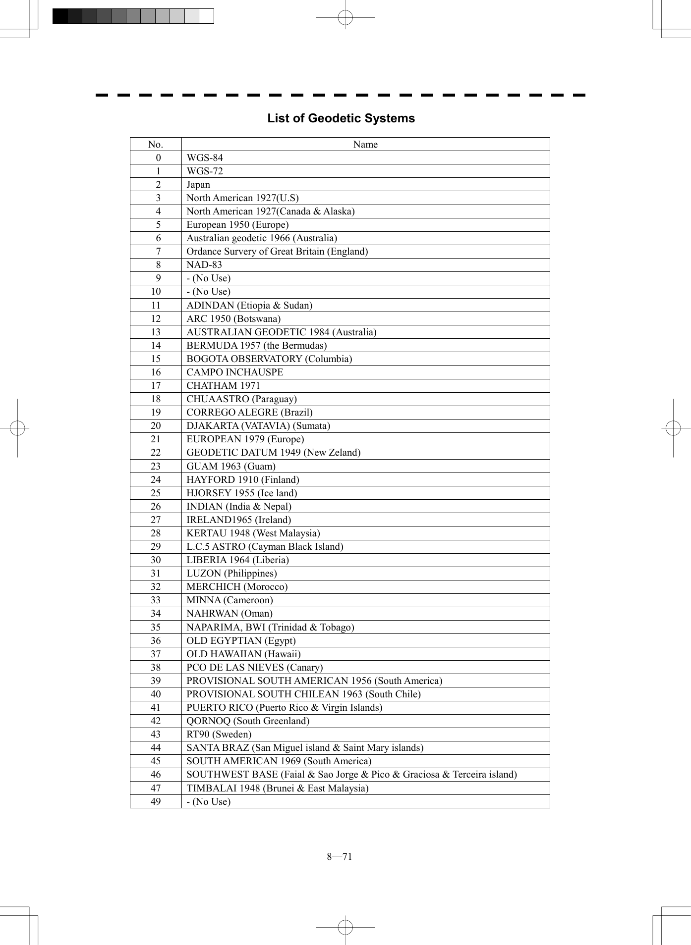
![8─72 88.6 Setting GPS Process Setting1. Position00’00.000000’00.0000. EXIT003. GeodeticNE2. Exclution00 00 00 00 00 00WGS-844. Antenna Height0m5. Fix Mode 2D6. DOP LevelUp to 57. Position AverageLONG8. Master ResetOFF9. Send Data[IV] Antenna Height Setting (Antenna Height) Procedures 1 Press [RADAR MENU] key twice. The Radar Menu will appear. 3 Press [7] key. NAV Equipment Setting Menu will appear. 4 Press [7] key. GPS Setting Menu will appear. 5 Press [1] key. GPS Process Setting Menu will appear. 6 Press [4] key. The Code Input menu will appear. Enter the antenna height of the own ship. The multi-function control is also available to enter the values. 7 After having entered the value, press [9] key, and transmit the contents of the settings to the GPS receiver. Exit 1 Press [RADAR MENU] key. The Main Menu will reappear.](https://usermanual.wiki/Japan-Radio/NKE2252.Instruction-manual-2-of-3/User-Guide-482879-Page-173.png)
![8─73 GPS Process Setting1. Position00’00.000000’00.0000. EXIT 00 3. GeodeticNE2. Exclution00 00 00 00 00 00WGS-844. Antenna Height0m5. Fix Mode 2D6. DOP LevelUp to 57. Position AverageLONG8. Master ResetOFF9. Send Data[V] Fix Mode Setting (Fix Mode) Set the GPS fix mode. Procedures 1 Press [RADAR MENU] key twice. The Radar Menu will appear. 2 Press [7] key. NAV Equipment Setting Menu will appear. 3 Press [7] key. GPS Setting Menu will appear. 4 Press [1] key. GPS Process Setting Menu will appear. 5 Press [5] key. From the pull-down menu, you can select the following modes. 2D: 2D positioning only. Height cannot be acquired. 3D: 3D positioning can be done with height acquired. AUTO: 2D positioning and 3D positioning can automatically be selected with optimum. 7 After having entered the values, press [9] key to transmit the setting contents to the GPS receiver. Exit 1 Press [RADAR MENU] key. The Main Menu will reappear.](https://usermanual.wiki/Japan-Radio/NKE2252.Instruction-manual-2-of-3/User-Guide-482879-Page-174.png)
![8─74 88.6 Setting GPS Process Setting1. Position00’00.000000’00.0000. EXIT003. GeodeticNE2. Exclution00 00 00 00 00 00WGS-844. Antenna Height0m5. Fix Mode 2D6. DOP LevelUp to 57. Position AverageLONG8. Master ResetOFF9. Send Data[VI] HDOP Level Setting (DOP Level) Set the HDOP level of the GPS receiver. Procedures 1 Press [RADAR MENU] key twice. The Radar Menu will appear. 2 Press [7] key. NAV Equipment Setting Menu will appear. 3 Press [7] key. GPS Setting Menu will appear. 4 Press [1] key. GPS Process Setting Menu will appear. 5 Press [6] key. From the pull-down menu, you can select a desired level. As the value is smaller, the precision becomes higher, but positioning grows more difficult. 6 After having entered the values, press [9] key to transmit the setting contents to the GPS receiver. Exit 1 Press [RADAR MENU] key. The Main Menu will reappear.](https://usermanual.wiki/Japan-Radio/NKE2252.Instruction-manual-2-of-3/User-Guide-482879-Page-175.png)
![8─75 GPS Process Setting1. Position00’00.000000’00.0000. EXIT 00 3. GeodeticNE2. Exclution00 00 00 00 00 00WGS-844. Antenna Height0m5. Fix Mode 2D6. DOP LevelUp to 57. Position AverageLONG8. Master ResetOFF9. Send Data[VII] Average Level Setting (Position Average) Set the time to average position information etc. output from the GPS receiver. Procedures 1 Press [RADAR MENU] key twice. The Radar Menu will appear. 2 Press [7] key. NAV Equipment Setting Menu will appear. 3 Press [7] key. GPS Setting Menu will appear. 4 Press [1] key. GPS Process Setting Menu will appear. 5 Press [7] key. From the pull-down menu, select the following: LONG, STANDARD, and NONE. The degree of average becomes small in order of LONG, STANDARD and NONE. As the degree of average is smaller, the update speed of position information is higher but dispersion is larger. 6 After having entered the values, press [9] key to transmit the setting contents to the GPS receiver. Exit 1 Press [RADAR MENU] key. The Main Menu will reappear.](https://usermanual.wiki/Japan-Radio/NKE2252.Instruction-manual-2-of-3/User-Guide-482879-Page-176.png)
![8─76 88.6 Setting GPS Process Setting1. Position00’00.000000’00.0000. EXIT00 3. GeodeticNE2. Exclution00 00 00 00 00 00WGS-844. Antenna Height0m5. Fix Mode 2D6. DOP LevelUp to 57. Position AverageLONG8. Master ResetOFF9. Send Data[VII] Master Reset (Master Reset) Transmit the master reset to the GPS receiver to initialize the GPS receiver. Procedures 1 Press [RADAR MENU] key twice. The Radar Menu will appear. 2 Press [7] key. NAV Equipment Setting Menu will appear. 3 Press [7] key. GPS Setting Menu will appear. 4 Press [1] key. GPS Process Setting Menu will appear. 5 Press [8] key. Switching between ON and OFF is done each time you press [8] key Select ON to transmit the reset. 6 After having entered the values, press [9] key to transmit the setting contents to the GPS receiver. Exit 1 Press [RADAR MENU] key. The Main Menu will reappear.](https://usermanual.wiki/Japan-Radio/NKE2252.Instruction-manual-2-of-3/User-Guide-482879-Page-177.png)
![8─77 DGPS Setting1. Mode AUTO0. EXIT 2. Frequency5. Send Data275.0KHz3. Baud Rate (BPS)50 4. DGPS ModeON Status No Beacon RCV connectionFrequency --- KHzBaud Rate --- BaudRSSI ---Setting in DGPS Receiver (DGPS Setting) Set an initial value in the DGPS receiver (our DGPS receiver). [I] DGPS Mode Setting (Mode) Procedures 1 Press [RADAR MENU] key twice. The Radar Menu will appear. 2 Press [7] key. NAV Equipment Setting Menu will appear. 3 Press [7] key. GPS Setting Menu will appear. 4 Press [2] key. DGPS Setting Menu will appear. 5 Press [1] key. Each time [1] key is pressed, AUTO/MANUAL is toggled. Auto: Automatically sets the working frequency of Beacon station. Manual: Manually sets the working frequency. (From the next page) 6 After having entered the value, press [5] key to transmit the setting contents to the DGPS receiver. Exit 1 Press [RADAR MENU] key. The Main Menu will reappear.](https://usermanual.wiki/Japan-Radio/NKE2252.Instruction-manual-2-of-3/User-Guide-482879-Page-178.png)
![8─78 88.6 Setting DGPS Setting1. ModeAUTO0. EXIT2. Frequency5. Send Data275.0KHz3. Baud Rate (BPS)50 4. DGPS ModeON Status No Beacon RCV connectionFrequency --- KHzBaud Rate --- BaudRSSI ---[II] Setting of Working Frequency of Beacon Station (Frequency) This setting can be made only when Manual is selected in 1. Mode. Procedures 1 Press [RADAR MENU] key twice. The Radar Menu will appear. 2 Press [7] key. NAV Equipment Setting Menu will appear. 3 Press [7] key. GPS Setting Menu will appear. 4 Press [2] key. DGPS Setting Menu will appear. 5 Press [2] key. The Code Input menu will appear. Enter the working frequency of the Beacon station. The multi-function control is also available for the entry. 6 After having entered the value, press [5] key to transmit the setting contents to the DGPS receiver. Exit 1 Press [RADAR MENU] key. The Main Menu will reappear.](https://usermanual.wiki/Japan-Radio/NKE2252.Instruction-manual-2-of-3/User-Guide-482879-Page-179.png)
![8─79 DGPS Setting1. Mode AUTO0. EXIT 2. Frequency5. Send Data275.0KHz3. Baud Rate (BPS)50 4. DGPS ModeON Status No Beacon RCV connectionFrequency --- KHzBaud Rate --- BaudRSSI ---[III] Setting of Communication Baud Rate with Beacon Station (BPS) This setting can be made only when Manual is selected in 1. Mode. Procedures 1 Press [RADAR MENU] key twice. The Radar Menu will appear. 3 Press [7] key. NAV Equipment Setting Menu will appear. 4 Press [7] key. GPS Setting Menu will appear. 5 Press [2] key. DGPS Setting Menu will appear. 6 Press [3] key. From the pull-down menu, you can select the following transmission speeds. 50bps 100bps 200bps Set the desired communication speed. 7 After having entered the value, press [5] key to transmit the setting contents to the DGPS receiver. Exit 1 Press [RADAR MENU] key. The Main Menu will reappear.](https://usermanual.wiki/Japan-Radio/NKE2252.Instruction-manual-2-of-3/User-Guide-482879-Page-180.png)
![8─80 88.6 Setting DGPS Setting1. ModeAUTO0. EXIT2. Frequency5. Send Data275.0KHz3. Baud Rate (BPS)50 4. DGPS ModeON Status No Beacon RCV connectionFrequency --- KHzBaud Rate --- BaudRSSI ---[IV] DGPS Mode Setting (DGPS Mode) Set the DGPS mode to ON/OFF. Setting the mode to ON allows you to acquire highly precise position information by using information from the Beacon station. Setting the mode to OFF allows you to acquire position information with the same precision as that of GPS. Procedures 1 Press [RADAR MENU] key twice. The Radar Menu will appear. 2 Press [7] key. NAV Equipment Setting Menu will appear. 3 Press [7] key. GPS Setting Menu will appear. 4 Press [2] key. DGPS Setting Menu will appear. 5 Press [4] key. Switching between ON and OFF is done each time you press [4] key. 6 After having entered the value, press [5] key to transmit the setting contents to the DGPS receiver. Exit 1 Press [RADAR MENU] key. The Main Menu will reappear.](https://usermanual.wiki/Japan-Radio/NKE2252.Instruction-manual-2-of-3/User-Guide-482879-Page-181.png)
![8─81 WAAS Setting1. Mode AUTO0. EXIT 2. Ranging6. Send DataON 3. NG WAASNOT USE4. WAAS Select ModeAUTO 5. WAAS No.120 Setting in WAAS Receiver (WAAS Setting) Make settings in the WAAS receiver (our WAAS receiver). Because the information the WAAS receiver receives from the satellite also includes the same information as that from DGPS Beacon station, it can perform positioning with higher precision than GPS. [I] WAAS Mode Setting (Mode) Set whether or not differential information of the WAAS receiver is acquired from the Beacon or satellite. Procedures 1 Press [RADAR MENU] key twice. The Radar Menu will appear. 2 Press [7] key. NAV Equipment Setting Menu will appear. 3 Press [7] key. GPS Setting Menu will appear. 4 Press [3] key. WAAS Setting Menu will appear. 5 Press [1] key. From the pull-down menu, select the following: BEACON, WAAS, or AUTO. 6 After having made entry, press [6] key to transmit the setting contents to the WAAS receiver. Exit 1 Press [RADAR MENU] key. The Main Menu will reappear.](https://usermanual.wiki/Japan-Radio/NKE2252.Instruction-manual-2-of-3/User-Guide-482879-Page-182.png)
![8─82 88.6 Setting WAAS Setting1. ModeAUTO 0. EXIT2. Ranging6. Send DataON 3. NG WAASNOT USE4. WAAS Select ModeAUTO 5. WAAS No.120 [II] Positioning Satellite Selection/Setting (Ranging) Set whether or not the WAAS satellite is to be used as a positioning satellite. Procedures 1 Press [RADAR MENU] key twice. The Radar Menu will appear. 2 Press [7] key. NAV Equipment Setting Menu will appear. 3 Press [7] key. GPS Setting Menu will appear. 4 Press [3] key. WAAS Setting Menu will appear. 5 Press [2] key. Switching between ON (use) and OFF (not use) is done each time you press [2] key. 6 After having made entry, press [6] key to transmit the setting contents to the WAAS receiver. Exit 1 Press [RADAR MENU] key. The Main Menu will reappear.](https://usermanual.wiki/Japan-Radio/NKE2252.Instruction-manual-2-of-3/User-Guide-482879-Page-183.png)
![8─83 WAAS Setting1. Mode AUTO 0. EXIT 2. Ranging6. Send DataON 3. NG WAASNOT USE4. WAAS Select ModeAUTO 5. WAAS No.120 [III] Setting of Availability of Banned Satellite (NG WAAS) Set whether or not the information from the banned WAAS satellite is to be used. Procedures 1 Press [RADAR MENU] key twice. The Radar Menu will appear. 2 Press [7] key. NAV Equipment Setting Menu will appear. 3 Press [7] key. GPS Setting Menu will appear. 4 Press [3] key. WAAS Setting Menu will appear. 5 Press [2] key. Switching between USE (use) and NOT USE (not use) is done each time you press [2] key. 6 After having made entry, press [6] key to transmit the setting contents to the WAAS receiver. Exit 1 Press [RADAR MENU] key. The Main Menu will reappear.](https://usermanual.wiki/Japan-Radio/NKE2252.Instruction-manual-2-of-3/User-Guide-482879-Page-184.png)
![8─84 88.6 Setting WAAS Setting1. ModeAUTO0. EXIT2. Ranging6. Send DataON 3. NG WAASNOT USE4. WAAS Select ModeAUTO 5. WAAS No.120 [IV] Satellite Number Setting (WAAS Select Mode) Set the number of the WAAS satellite to be used. Procedures 1 Press [RADAR MENU] key twice. The Radar Menu will appear. 2 Press [7] key. NAV Equipment Setting Menu will appear. 3 Press [7] key. GPS Setting Menu will appear. 4 Press [3] key. WAAS Setting Menu will appear. 5 Press [4] key. Switching between Auto and Manual is done each time you press [4] key. 6 After having made entry, press [6] key to transmit the setting contents to the WAAS receiver. Exit 1 Press [RADAR MENU] key. The Main Menu will reappear.](https://usermanual.wiki/Japan-Radio/NKE2252.Instruction-manual-2-of-3/User-Guide-482879-Page-185.png)
![8─85 WAAS Setting1. Mode AUTO0. EXIT 2. Ranging6. Send DataON 3. NG WAASNOT USE4. WAAS Select ModeAUTO 5. WAAS No.120 [V] Satellite Number Setting (WAAS Select Mode) Set the number of the WAAS satellite to be used. Procedures 1 Press [RADAR MENU] key twice. The Radar Menu will appear. 2 Press [7] key. NAV Equipment Setting Menu will appear. 3 Press [7] key. GPS Setting Menu will appear. 4 Press [3] key. WAAS Setting Menu will appear. 5 Press [5] key. The Code Input menu will appear. Enter numeric values between Nos.120 and 138. The multi-function control is also available to enter the values. 6 After having made entry, press [6] key to transmit the setting contents to the WAAS receiver. Exit 1 Press [RADAR MENU] key. The Main Menu will reappear.](https://usermanual.wiki/Japan-Radio/NKE2252.Instruction-manual-2-of-3/User-Guide-482879-Page-186.png)
![8─86 88.6 Setting GPS Setting1. GPS Process Setting0. EXIT 2. DGPS Setting3. WAAS Setting4. GPS StatusGPS Reception Status Display (GPS Status) Display the reception status of the GPS receiver (GPS, DGPS and WAAS receivers) currently connected. Seize the status of satellites that are currently performing positioning. Procedures 1 Press [RADAR MENU] key twice. The Radar Menu will appear. 2 Press [7] key. NAV Equipment Setting Menu will appear. 3 Press [7] key. GPS Setting Menu will appear. 4 Press [4] key. GPS Status Menu will appear. Exit 1 Press [0] key. The Status Menu will be closed. 2 Press [RADAR MENU] key. The menu will be closed.](https://usermanual.wiki/Japan-Radio/NKE2252.Instruction-manual-2-of-3/User-Guide-482879-Page-187.png)
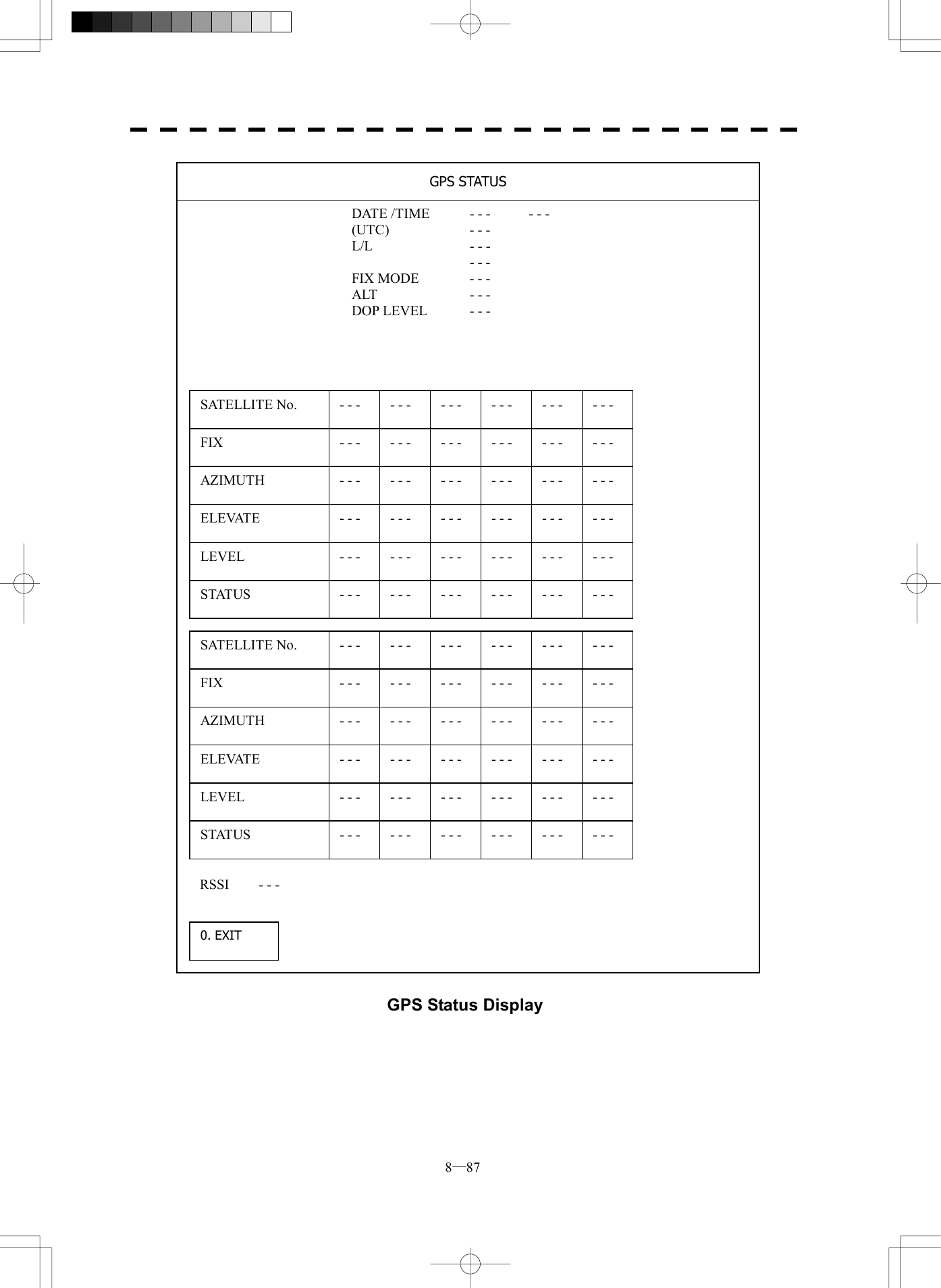
![8─89 Date/Time Setting1. UTC/LOCALOFF2. Local Date1971/01/0100:000. EXIT 3. Local Time+00:004. Time ZoneDate/Time Display Setting (Date/Time Setting) In displaying the time, it is necessary to set the LOCAL TIME, LOCAL DATE and GMT+/-. Procedures 1 Press [RADAR MENU] key twice. The RADAR Menu will appear. 2 Press [8] key. The RADAR SUB Menu will appear. 3 Press [4] key. The Date/Time Setting Menu will appear. 4 Press [1] key. 1. UTC/LOCAL will be selected. The setting is switched back and forth between UTC (Coordinate Universal Time) and LOCAL (local time) each time [1] key is pressed. 5 Press [2] key. The Code Input Menu will appear. 6 Enter the date. The date will be set. The multi-function control is also available for the entry. After having enter the date, press ENT. 7 Press [3] key. The Code Input Menu will appear.](https://usermanual.wiki/Japan-Radio/NKE2252.Instruction-manual-2-of-3/User-Guide-482879-Page-190.png)
![8─90 88.6 Setting 8 Enter the time. The time will be set. The multi-function control is also available for the entry. After having enter the time, press ENT. 9 Press [4] key. The Code Input Menu will appear. 10 Enter the time difference. The time difference will be set. The multi-function control is also available for the entry. After having enter the value, press ENT. Exit 1 Press [RADAR MENU] key. The menu will be closed. l Time correction is not available when the “ZDA” sentence of NMEA0183 is not received. Attention](https://usermanual.wiki/Japan-Radio/NKE2252.Instruction-manual-2-of-3/User-Guide-482879-Page-191.png)
![8─91 Adjustment of Performance Monitor (NJU-63/64) * Execution of this item needs a PM unit (option). Procedures 1 Set the radar to Master Radar when the Interswitch is installed. 2 Press VRM1 key to display VRM1 and set the range of VRM1 to 10-18* NM. 3 The Equipment Setup Menu will appear in accordance with the instructions of section 8.5. 4 Press [4] key. The TRX Setting Menu will appear. 5 Press [4] key. The Code Input Menu will appear. 6 Enter a set value. Adjust the PM pattern so that its outer edge is within 10 to 18 NM. The multi-function control is also available for the entry. After having enter the value, press ENT. 7 Attach the INFORMATION LABEL provided with the performance monitor to an appropriate position on the display unit. TRX Setting1. Antenna Height5-10m8. Antenna Location0. EXIT 04. PM Adjustment20487. Output Pulse0m 0m](https://usermanual.wiki/Japan-Radio/NKE2252.Instruction-manual-2-of-3/User-Guide-482879-Page-192.png)
![8─92 88.6 Setting 8 Press [RADAR MENU] key twice. The RADAR Menu will appear. 9 Press [8] key. The RADAR Sub Menu will appear. 10 Press [9] key. The Test Menu will appear. 11 Press [4] key, and set PM Display to ON. The PM bar will appear. 12 Write the value indicated by the PM bar and the check date to the INFORMATION LABEL you have attached to the display unit in step 7. Test Menu 1. Self Test2. Monitor Test3. Panel Test4. PM DisplayON5. Error Logging6. System INFO0. EXITMAGI PM](https://usermanual.wiki/Japan-Radio/NKE2252.Instruction-manual-2-of-3/User-Guide-482879-Page-193.png)
![8─93 Exit 1 Press [RADAR MENU] key. The menu will be closed. Note: · All target acquisitions by ARPA functions will be cancelled when PM is ON. The target acquisition cancelled will not be recovered. · The radar image is suppressed to make the PM image easier to see. Therefore, the PM Display should be turned OFF after PM check is completed. Adjust the PM pattern using the ten-key or multi-function control so that its outer edge is within 10 to 18 NM. PM Pattern 10 to 18 NMHL](https://usermanual.wiki/Japan-Radio/NKE2252.Instruction-manual-2-of-3/User-Guide-482879-Page-194.png)