Japan Radio NKE2252 25KW X-Band Radar Transceiver User Manual
Japan Radio Co Ltd. 25KW X-Band Radar Transceiver
Contents
- 1. Instruction manual 1 of 3
- 2. Instruction manual 2 of 3
- 3. Instruction manual 3 of 3
Instruction manual 2 of 3
SECTION 4
MEASUREMENT OF
RANGE AND BEARING
4.1 Measurement by Trackball ............................. 4-1
4.2 Measurement by Range Rings ....................... 4-2
4.3 Measurement by EBLs and VRMs ................. 4-3
4.4 Measurement between Two Optional Points. 4-5
4─1
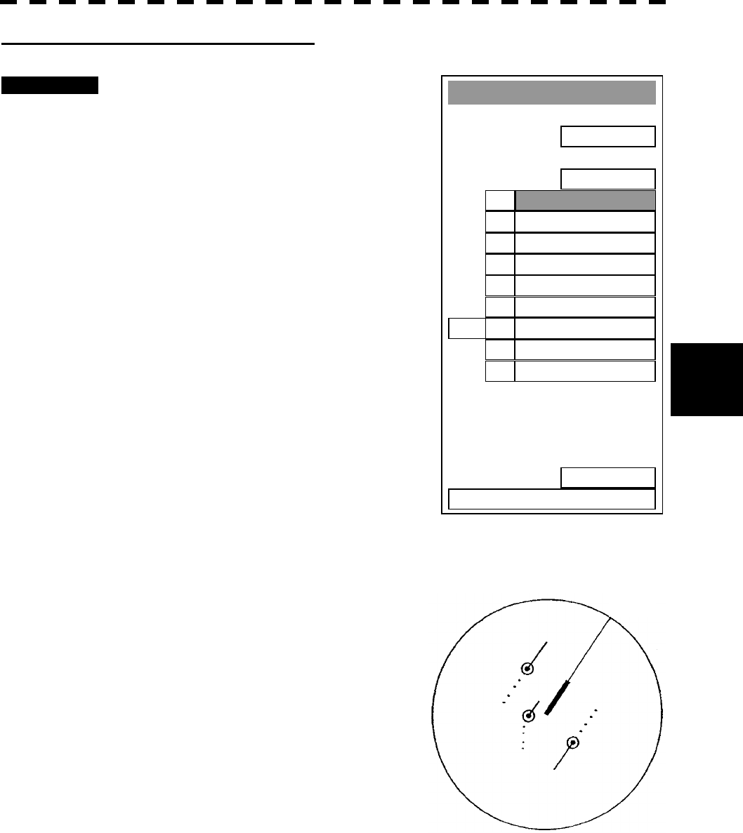
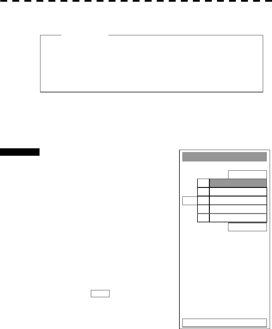
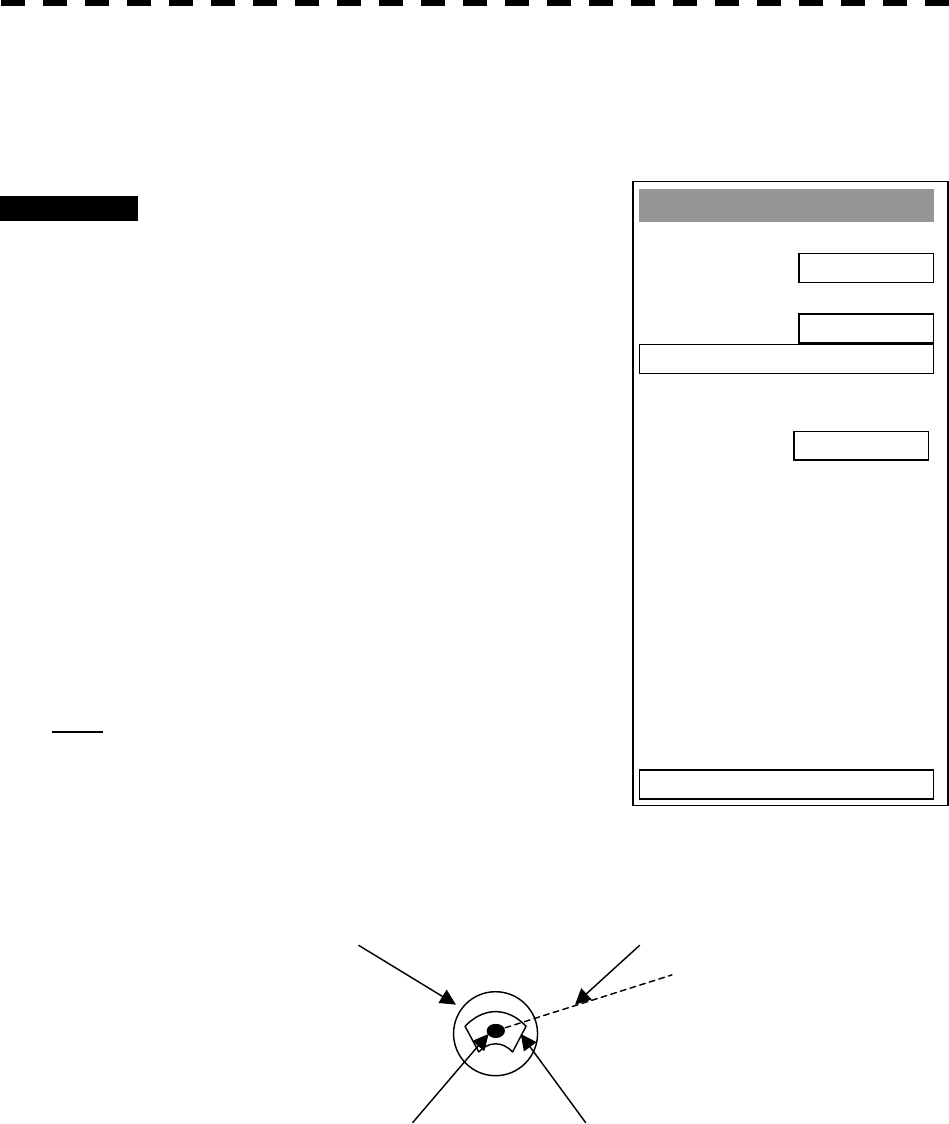
4.1 MEASUREMENT BY TRACKBALL
Procedures 1 Check the target echoes on the radar display.
2 Move the cursor mark to a target by the trackball.
The CURSOR on the radar display indicates the bearing and range of the target.
The range is a distance from own ship’s position.
CURSOR ( )
TRUE 45.0°: True bearing of the cursor relative to own ship
5.0nm: Range between the cursor and own ship
REL 45.0°: Relative bearing of the cursor relative to own ship
Figure 4.1
Target Curso
r
Own ship

4─2
4
4.2 MEASUREMENT BY RANGE RINGS
Procedures 1 Press [RR/HL] key.
The Range Rings will appear on the radar display.
The range between the target and own ships can be determined by visually measuring
the target’s position that lies between two range rings.
(The range ring interval is fixed and indicated within the radar display on page 2-9.)
4─3
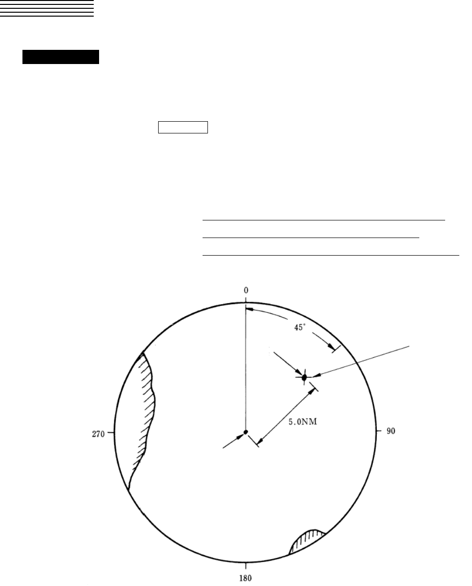
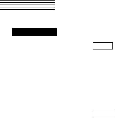
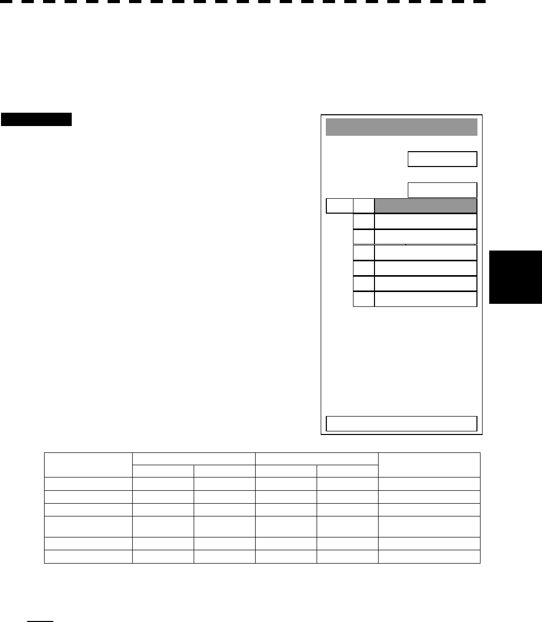
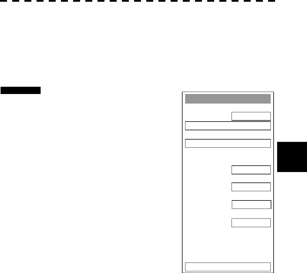
4.3 MEASUREMENT BY EBLS AND VRMS ・・
Procedures 1 Press [EBL1] key to select EBL1 display and operation.
The EBL1 indication at the lower right of the radar display will be selected and the
EBL1 will appear as a broken-line on the PPI display.
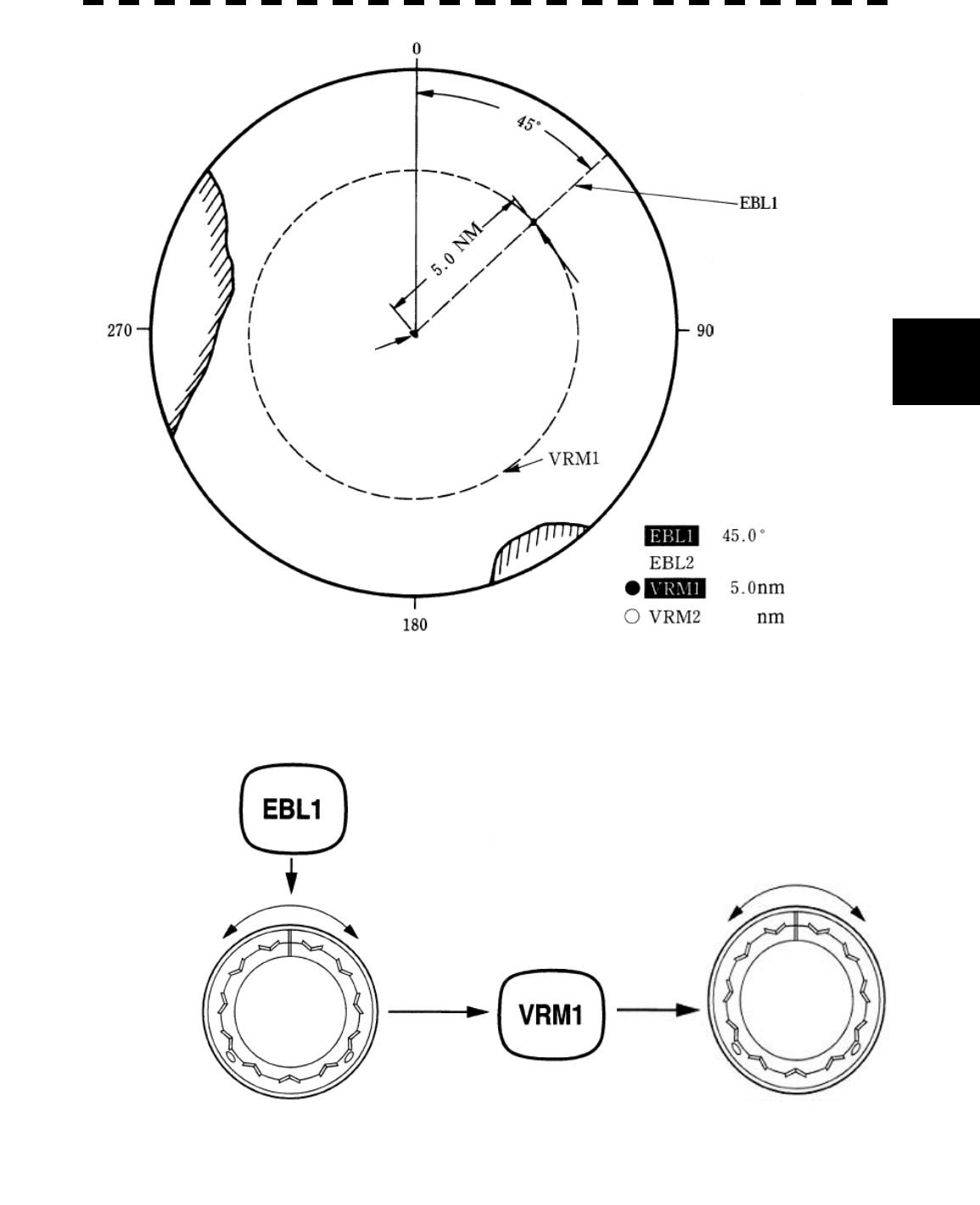
2 Turn the [EBL] control to put EBL1 on a target.
The bearing of the EBL1 will appear at the lower right of the radar display. The EBL1
bearing represents the target’s bearing.
3 Press [VRM1] key to select VRM1 display and operation.
The VRM1 indication at the lower right of the radar display will be selected and the
VRM1 will appear as a broken-line circle on the PPI display.
4 Move the broken-line VRM1 to the target by using the [VRM]
control.
The range of the VRM1 from own ship will appear at the lower right of the radar
display. The range of VRM1 signifies a distance between the target and own ship.
Refer to Figure 4.2 in the next page.
In this Figure 4.2, the range and bearing are;
Range: 5.0nm
Bearing: 45.0°
4─4
4
4.3 MEASUREMENT BY EBLS AND VRMS
Figure 4.2
VRM Control
EBL Control
Target
Own ship
4─5
123.4EBL1 T °C
004.3EBL2 T °C
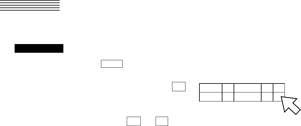
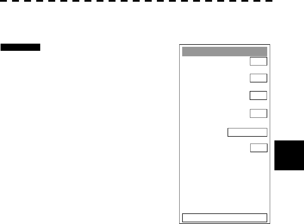
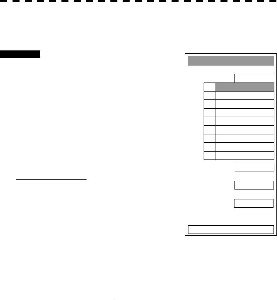
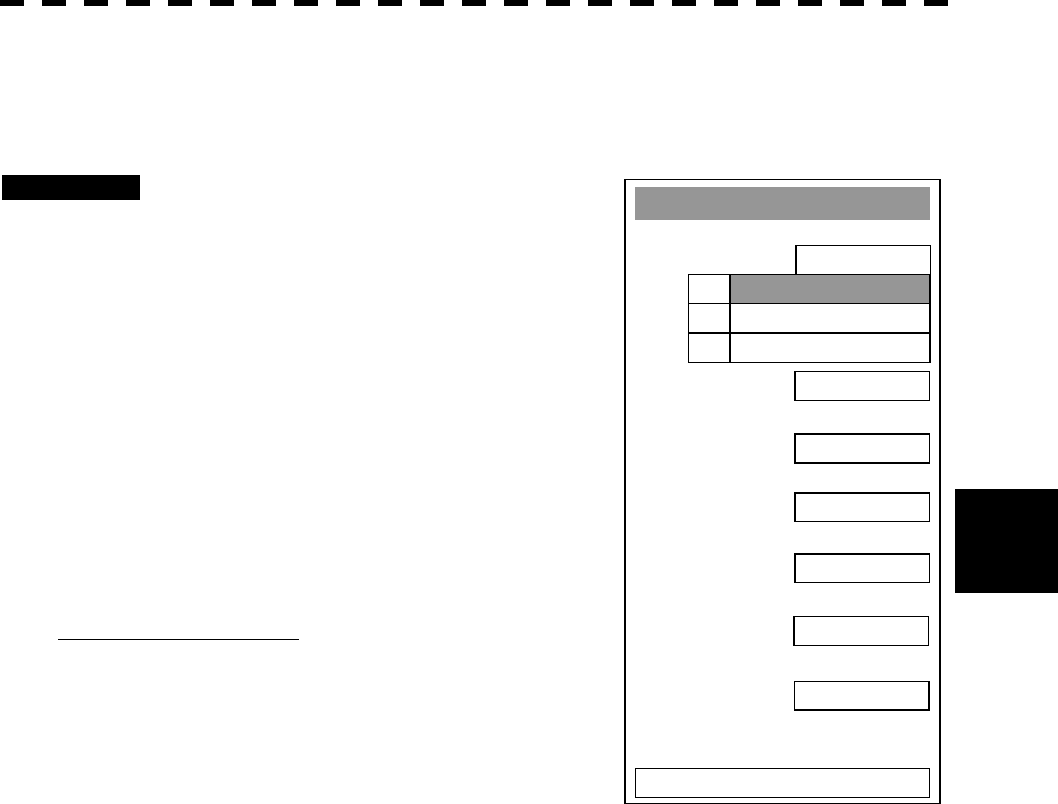
4.4 MEASUREMENT BETWEEN TWO
OPTIONAL POINTS
Procedures 1 Press [EBL2] key to select EBL2 display and operation.
The EBL2 indication at the lower right of the radar display will be selected and the
EBL2 will appear as a dotted-line on the PPI display.
2 Point the cursor to the C
switch of EBL2 at the lower
right of the radar display, and
press [ENT] key. The EBL cursor mode changes
each time O or L is pressed.
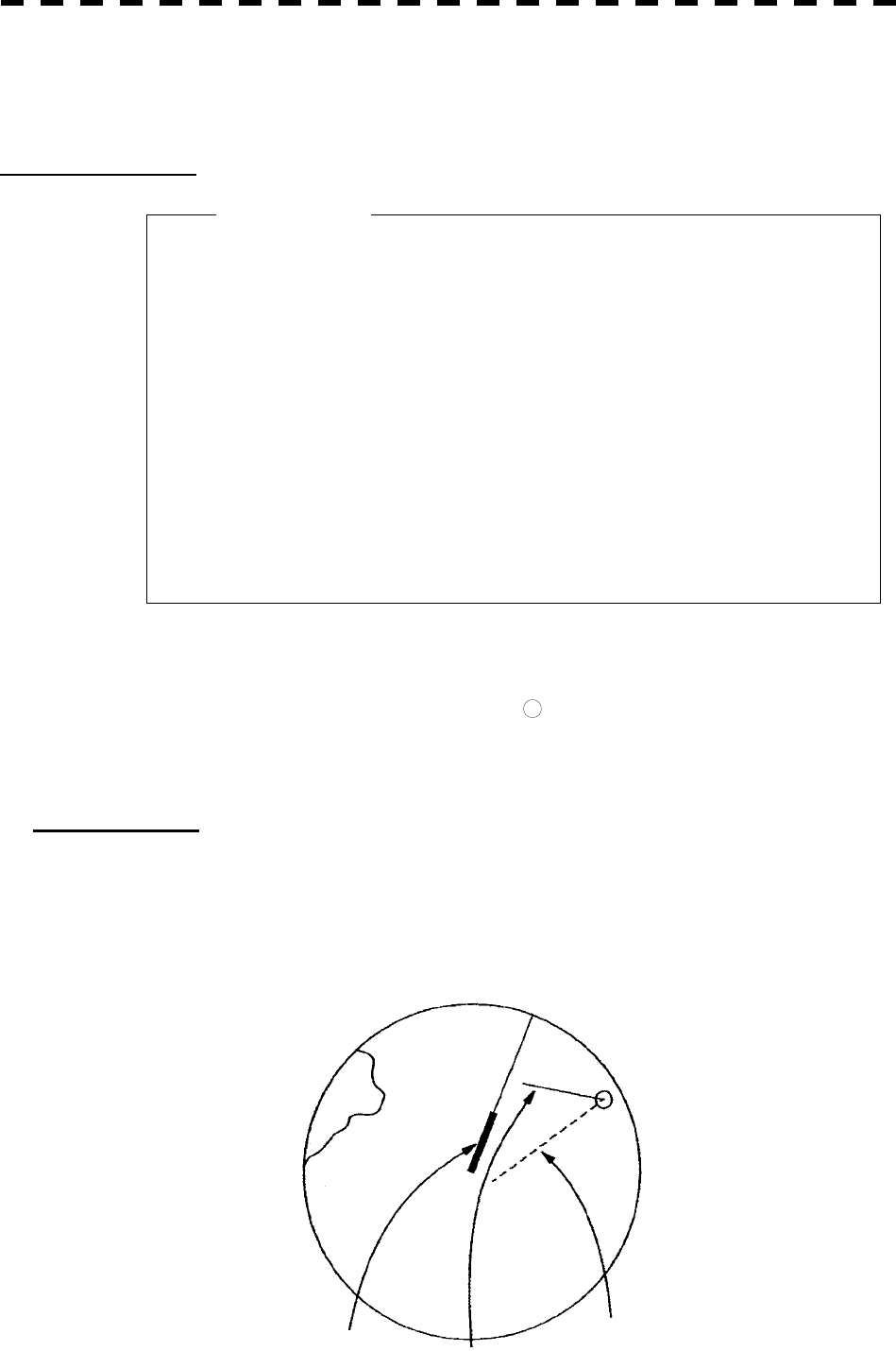
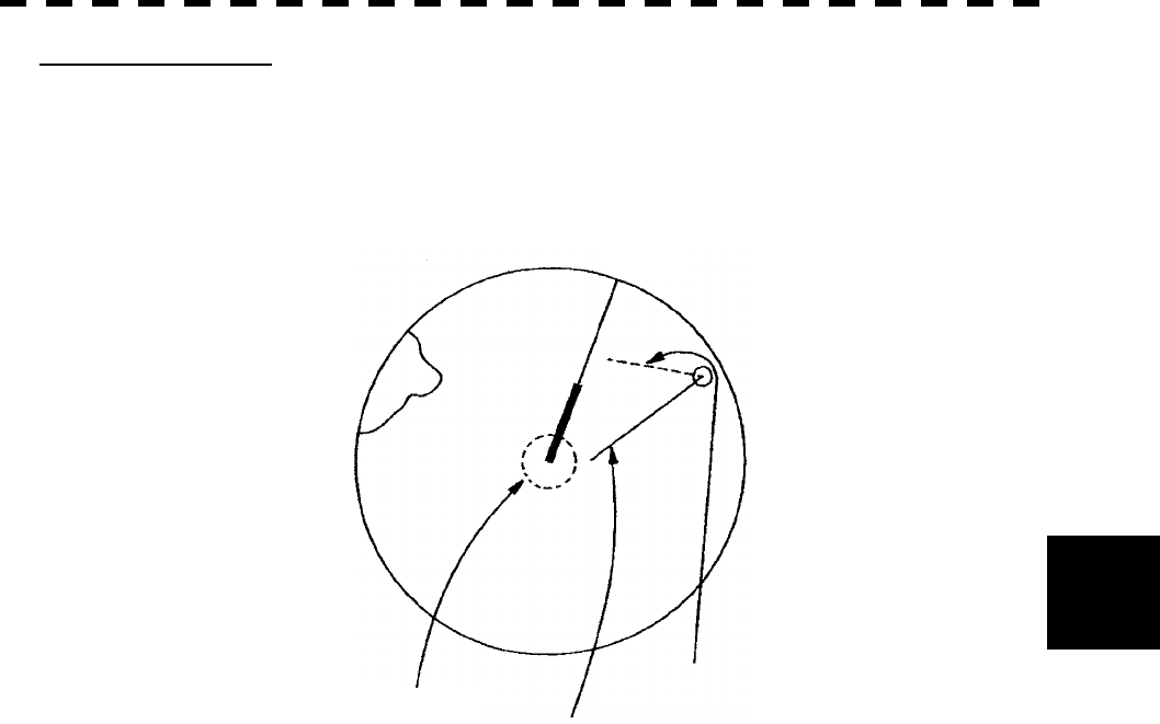
3 Using the trackball, move the starting point of EBL2 to one
(A) of the two points and press [ENT] key.
(See Figure 4.3.)
4 Turn the [EBL] control to move EBL2 to the other point (B).
(See Figure 4.3.)
5 Press [VRM2] key to select VRM2 display and operation.
¡ (VRM marker) will appear on a dotted-line of the EBL2.
6 Using the [VRM] control, move the VRM2 marker on a
dotted-line of EBL2 to the point B.
The bearing and range between the two points will appear in the VRM2 and EBL2 area
on the lower right of the radar display.
4─6
4
4.4 MEASUREMENT BETWEEN TWO OPTIONAL POINTS RINGS
Figure 4.3
It is also possible to use EBL1 instead of EBL2 in measuring the bearing and range
between two optional points.
In this case, read EBL2 as EBL1 and VRM2 as VRM1 in the procedure above, point the
cursor to C of EBL2 in step 2, and then press [ENT] key.
EBL Control
Starting point of EBL2
Cape
B
VRM2 Marker
Own ship
A
VRM Control

SECTION 5
OPERATION OF
ARPA AND AIS
5.1 PREPARATION........................................................... 5-2
5.1.1 Collision Avoidance ............................................ 5-4
5.1.2 Definitions of Symbols ....................................... 5-7
5.1.3 Setting Collision Decision Criteria
(CPA/TCPA Limit)................................................. 5-9
5.1.4 Setting Vectors (Vector Time)........................... 5-10
5.1.5 Setting CPA Ring (CPA Ring).............................5-11
5.1.6 Setting Automatic Acquisition Key Assignment
(GZ Alarm Key Setting) ................................... 5-12
5.2 EPA OPERATION ..................................................... 5-13
5.2.1 Plotting Targets ................................................. 5-13
5.2.2 Modifying Plotted Target Data .......................... 5-14
5.2.3 Canceling Plotted Target Data.......................... 5-14
5.2.4 Displaying Numeric Data of Plotted Targets.... 5-15
5.2.5 Setting EPA Alarm (Audible Warning).............. 5-16
5.3 ATA/ARPA OPERATION........................................... 5-17
5.3.1 Acquiring Target................................................ 5-17
5.3.2 Canceling Unwanted Targets............................ 5-19
5.3.3 Displaying Target ID No.
(Target Number Display) ................................... 5-20
5.3.4 ATA/ARPA Data Display .................................... 5-21
5.3.5 Target Data Display........................................... 5-26
5.3.6 Alarm Display .................................................... 5-30
5.3.7 Trial Maneuvering (Trial) ................................... 5-34
5.3.8 ATA/ARPA Simulation........................................ 5-38
5.3.9 Setting ATA/ARPA Tracks (ATA Track Setting). 5-44
5.4 AIS OPERATION....................................................... 5-51
5.4.1 Initial Setting...................................................... 5-52
5.4.2 Setting AIS Display Function (AIS Function)... 5-54
5.4.3 Activating AIS Targets....................................... 5-55
5.4.4 Deactivating AIS Targets................................... 5-56
5.4.5 Setting AIS Symbol Display Function
(AIS Symbol Display)......................................... 5-57
5.4.6 Displaying Numeric Data of AIS Targets .......... 5-58
5.4.7 Setting ATA/ARPA Symbol Display Function
(ATA Symbol Display) ........................................ 5-60
5.4.8 Setting AIS Filter (AIS Filter Setting)................ 5-61
5.4.9 Deciding AIS Target and ARPA Target as the
Same One (Identical Distance).......................... 5-64
5.4.10 Conditions for Deciding AIS Target to be Lost
............................................................................ 5-66
5.4.11 Displaying AIS Symbols.................................. 5-67
5.4.12 AIS Alarm Display............................................ 5-68
5.4.13 Restrictions...................................................... 5-69

5─1
USAGE OF ARPA
l There are the following limitations on use of the target acquisition and
tracking functions of ARPA.
[I] Resolution between adjacent targets and swapping during
automatic tracking
Depending on the particular distance and echo size, resolution between
adjacent targets during automatic tracking usually ranges somewhere
between 0.03 to 0.05 nm. If multiple targets approach each other,
resolution will become about 0.03 nm and this may cause the system to
regard them as one target and thus to swap them or lose part of them.
Such swapping or less of targets may also occur if the picture of the
target being tracked is affected by rain/snow clutter returns or sea
clutter returns or moves very close to land.
[II] Intensity of echoes and the tracking function
The intensity of echoes and the tracking function have a correlationship,
and thus the target will be lost if no echoes are detected during six
scans in succession. If a lost target exists, therefore, radar gain must
be increased to support detection of the target. If, however, radar gain is
increased too significantly, sea clutter returns or other noise may be
erroneously detected and tracked as a target, and resultingly, a false
alarm may be issued.
[III] Adverse effects of error sources on automatic tracking
To execute accurate tracking, it becomes necessary first to appropriatel
y
adjust the [GAIN], [SEA] and [RAIN] controls of the radar so that the
target to be acquired and tracked id clearly displayed on the radar
display. Inappropriate settings of these controls reduce the
reliability/accuracy of automatic tracking.
Attention

5─2
5
5.1 PREPARATION
This section explains the features of EPA/ATA/ARPA and AIS functions, and the initial setting for using each
function.
The four plotting functions below are available with this radar equipment.
An optional device is necessary for using each of the ATA, ARPA, and AIS functions.
EPA (Electronic Plotting Aid) function
The EPA function calculates the course and speed of a target from the positions of the target that have
been entered manually at specified intervals.
The EPA function is available when the ATA and ARPA options are not installed.
ATA (Automatic Tracking Aid) function
The ATA function calculates the course and speed of a target by automatically tracking the target’s move.
The ATA function enables automatic acquisition of targets by using the guard zone function.
The ATA function is available when the ATA option is installed.
(This function cannot be used with the ARPA option.)
ARPA (Automatic Radar Plotting Aid) function
The ARPA function calculates the course and speed of a target by automatically tracking the target’s
move.
The ARPA function enables automatic acquisition of targets by using the guard zone function.
The ARPA function also enables the simulation of the maneuvering method for avoiding collision by
using the trial maneuvering function.
The ARPA function is available when the ARPA option is installed.
The ARPA function provides higher-level functions than the ATA function.
(This function cannot be used with the ATA option.)
AIS (Automatic Identification System) function
The AIS function shows the target’s information on the radar display, using other ships’ information sent
out from the AIS unit.
The AIS function is available when the optional AIS interface is installed.

5─3
l The menu display is changed to “ATA” or “ARPA” according
to option provided in this radar equipment. Where the ARPA
option is provided, the ARPA Setting is displayed in the menu.
Also where the ATA option is provided, the ATA Setting is
displayed in the menu.
This manual basically displays using “ATA”.
Attention
5─4
5
5.1 PREPARATION
5.1.1 Collision Avoidance
Problems of Collision Avoidance in Navigation
Marine collision avoidance is one of the problems that have been recognized from of old. Now, it will be
described briefly who the collision avoidance is positioned among the navigational aid problems.
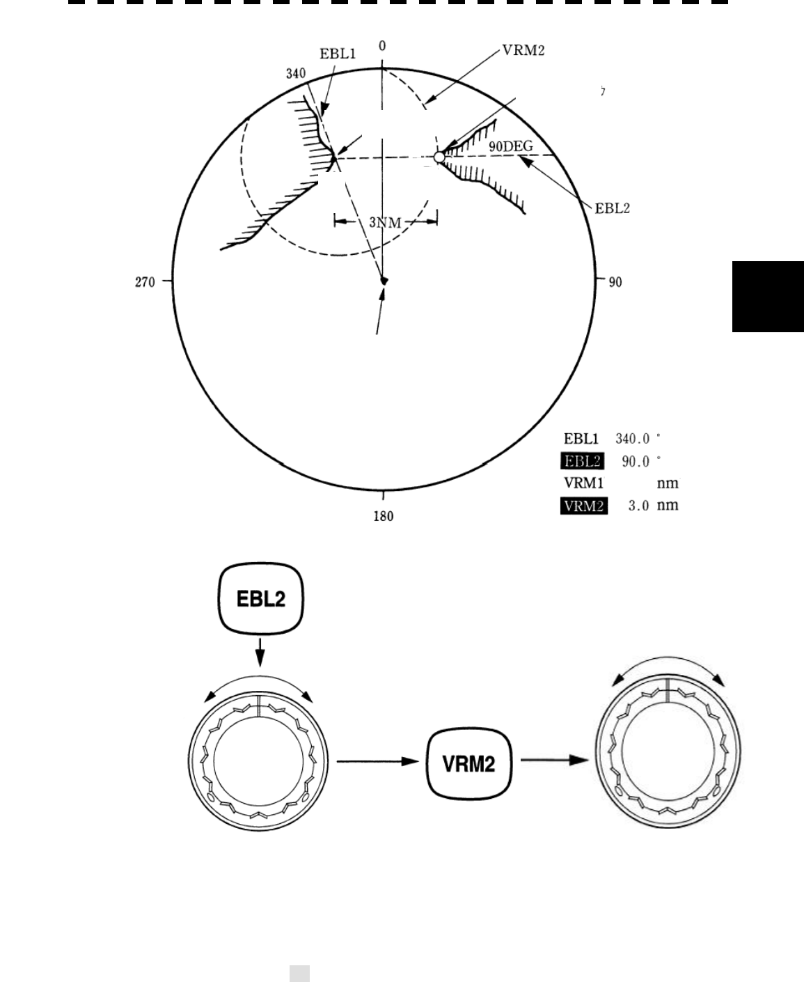
The navigation pattern of all mobile craft constitutes a system with some closed loops regardless of the media
through which the mobile craft travels, whether air, water, the boundary between air and water, or space. This
pattern consists of two closed loops in principle, one of which is a collision with another mobile craft and the
other is a loop of finding a right and safe way to reach a predeterminate destination. Fig. 5-1 shows the
conceptual diagram of navigation pattern by MR. E.W. Anderson. The closed loop of collision avoidance is
shown on the left side and the closed loop of finding a right course on the right side.
Fig. 5-1 Navigation Pattern
Marine Accidents and Collisions
Among marine accidents, collision accidents have been highlighted as the tonnages and speeds of ships become
higher along with the increase in traffic at sea. If a tanker carrying dangerous articles such as crude oil
collides with any other vessel, then not only the vessels involved with the accident but other vessels in the
vicinity, port facilities, inhabitants in the coastal area as well as marine resources may also suffer immeasurable
damages and troubles. Collision accidents have a high percentage of the marine accidents that have occurred
in recent years. To cope with these problems, any effective measures are needed and some equipment to
achieve collision avoidance requirements have been developed at rapid strides.
5─5
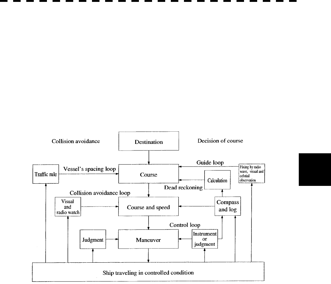
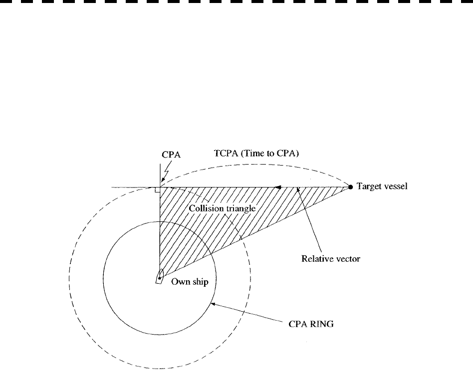
Basic Concept of Collision Avoidance
There are two aspects in collision avoidance: collision prediction and avoidance. Collision prediction is to
predict that two or more vessels will happen to occupy the same point at the same time, while collision
avoidance is to maneuver vessels not to occupy the same point at the same time.
In practical operation of vessels, a spot of collision has to be deemed to be a single point but a closed zone.
This closed zone is conceptually defined as a CPA (Closest Point of Approach). In collision prediction, the
time to be taken until a ship reaches the CPA is defined as a TCPA (Time to CPA).
Fig. 5-2 shows a diagram caked “Collision Triangle”.
Fig. 5-2 Collision Triangle
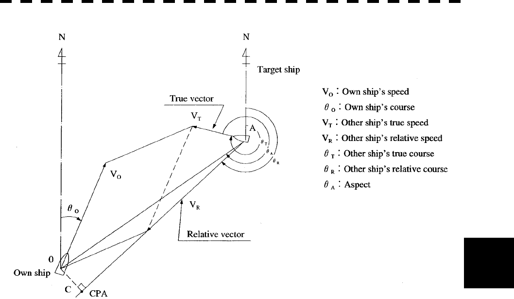
Relative Vector and True Vector
From two points of view, collision prediction and avoidance, it is necessary to obtain the relative vector of other
ship for prediction and the true vector of other ship for collision avoidance in order to grasp other ship’s aspect.
The relationship between the relative vector and true vector is shown in Fig. 5-3
Both rough CPA and TCPA can be obtained easily from the relative speed vector of other ship. This method
has an advantage that the risks of collision with all other ships within the radar range can be seen at a glance.
On the other hand, the course and speed of other ship can easily be obtained from its true speed vector, enabling
other ship’s aspect to be seen at a glance. Thus, the aspects of other ships (transverse, outsail, parallel run,
reverse run, etc. ) as described in the Act of Prevention of Collision at Sea can be readily grasped. If there is a
risk of collision with other ship, the operator can determine which rule to be applied and how to operate own
ship.
5─6
5
5.1 PREPARATION
Fig. 5-3 Relative Vector and True vector
Radar and Collision Avoidance
Radar is still playing an important roll for collision prevention and positioning. A plotter is used to further
enhance the radar functionality. The plotter is capable of plotting other positions of other ships in 3 to 6
minute intervals to monitor their movement. The plots of other ships represent their tracks relative to own
ship, and it is shown whether there is a risk of collision, namely CPA and TCPA can be obtained. This method
using a plotter is fairly effective, but the number of target ship, which are manually plotted, is limited and it
takes several minutes to measure those.
5─7
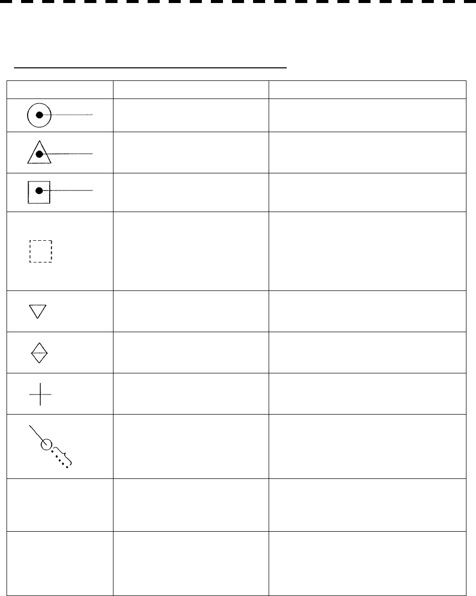
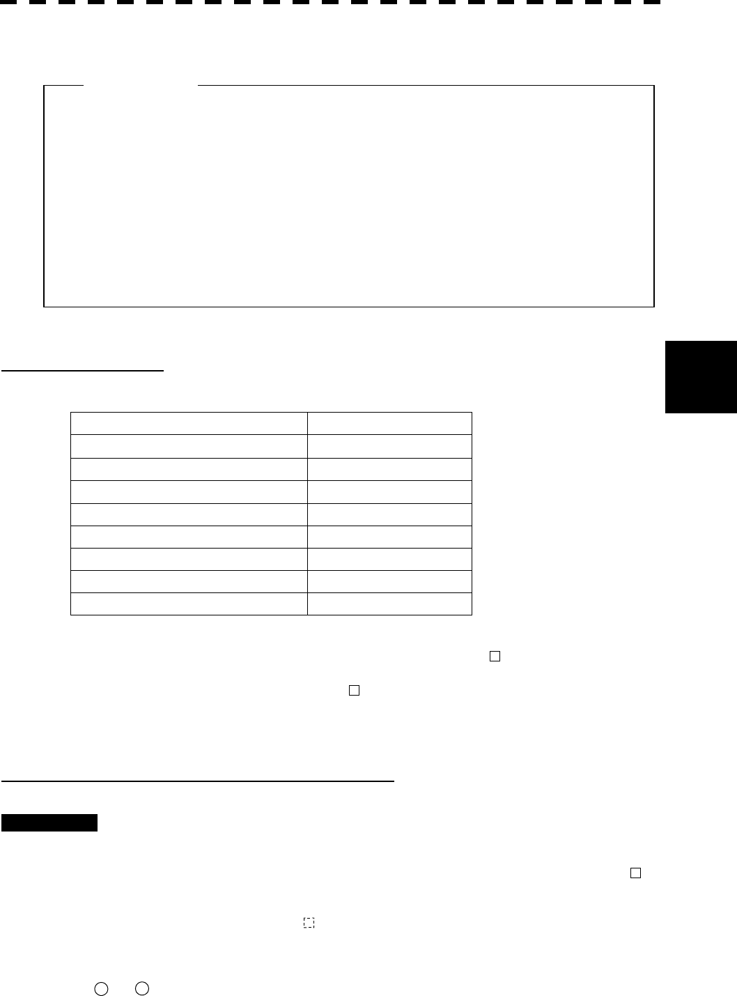
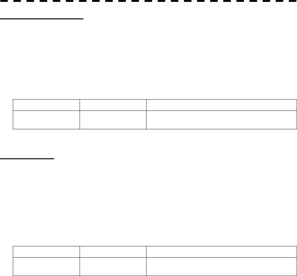
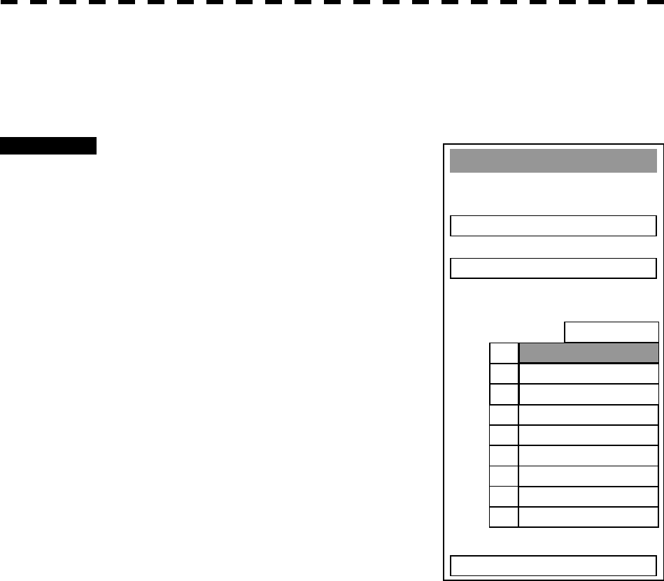
5.1.2 Definitions of Symbols
Types and Definitions of EPA, ATA, and ARPA Symbols
Vector/Symbol Definition Remarks
Safe target
Dangerous target
Alarm characters (CPA/TCPA) appear and an
alarm sounds.
The vector and symbol blinks with red lamp.
Target for which numeric data is
displayed
When numeric data is displayed, the target
symbol is changed into □.
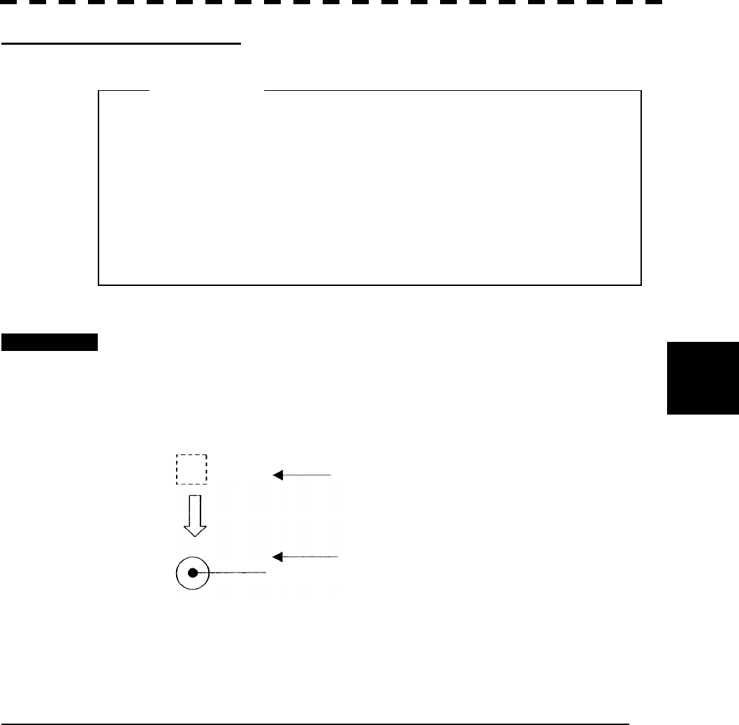
Initial acquisition mark
(EPA)
This symbol is displayed when the first
plotting is performed.
(ATA/ARPA)
This symbol is displayed until the vector is
displayed after target acquisition.
Target that has intruded into the
guard zone
Alarm characters (GZ) appear and an alarm
sounds.
The characters blinks with red lamp.
Lost target (a target that can not be
tracked for any reason)
Alarm characters (LOST) appear and an alarm
sounds. The symbol blinks. No vector is
displayed.
Trackball cross cursor mark
This mark is used to designate a target when
acquiring manually and canceling it and
indicating its numerical data.
A target’s past positions
The symbol and vector is displayed only when
[PAST POSN] is ON. The position interval
can be set to
OFF/0.5min/1min/2min/4min
0.1nm/0.2nm/0.5nm/1nm
M Plot data modification
This symbol is displayed only for (EPA).
“M” is shown beside the symbol indicating
that plotted target data is being modified.
The previous plotting position is displayed.
U Plot data update request
This symbol is displayed only for (EPA).
This symbol is displayed when plotted target
data is not updated for 10 minutes. When it is
not updated, the symbol disappears after 5
minutes. A LOST alarm sounds.
5─8
5
5.1 PREPARATION
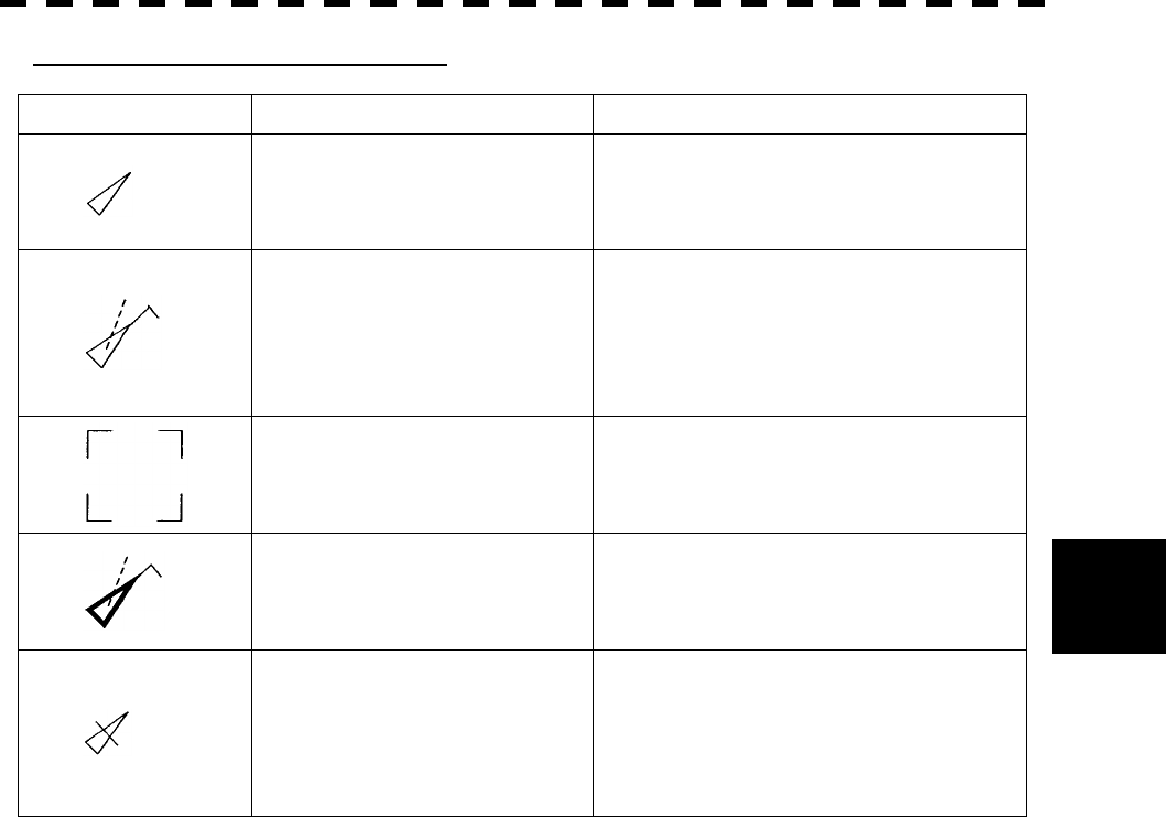
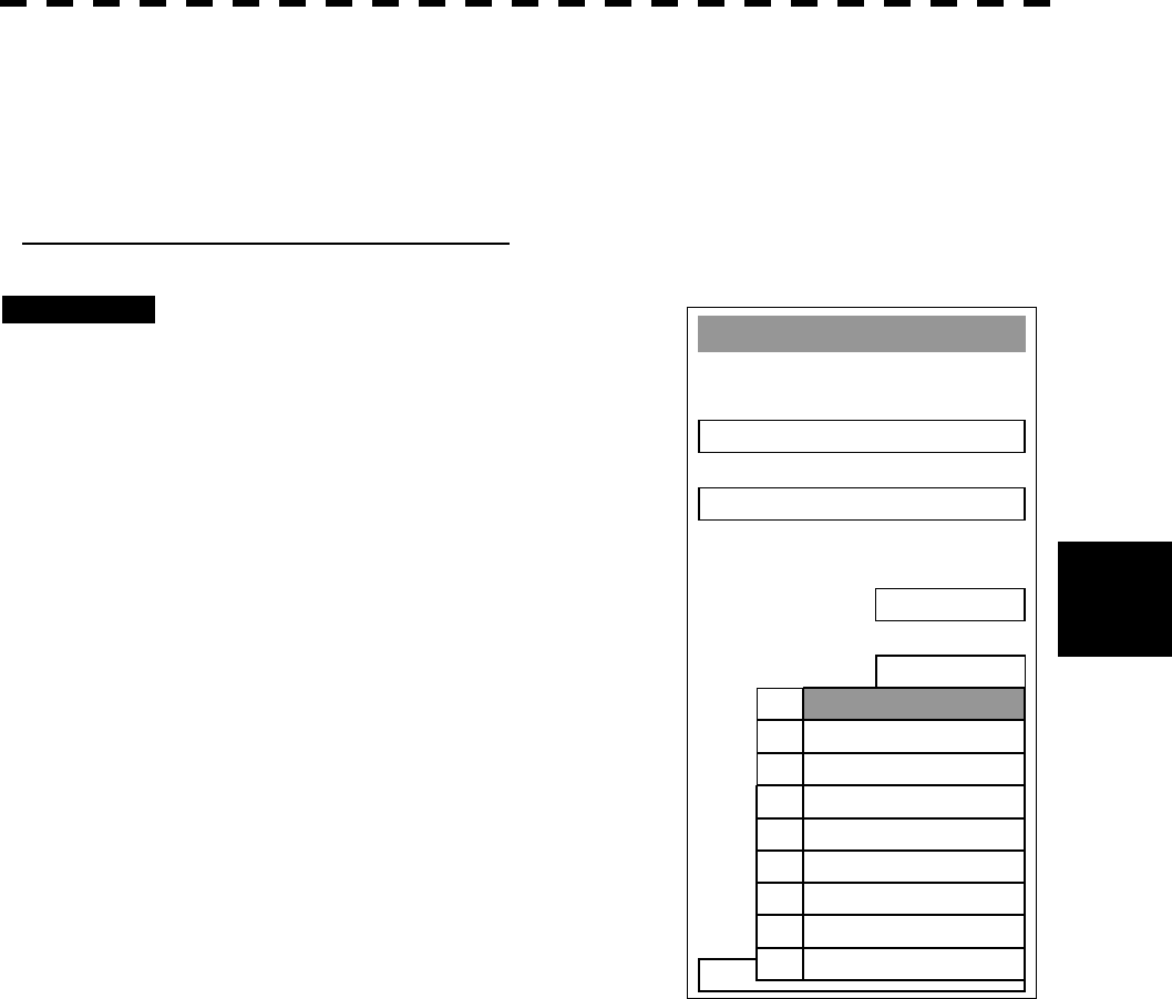
Types and Definitions of AIS Symbols
Vector/Symbol Definition Remarks
Sleeping target
This symbol is displayed when received data
is valid.
The direction of the triangle’s vertex indicates
the target’s bow or COG.
Activated target
The heading direction is displayed with a
solid line, and the COG vector is displayed
with a dotted line. The line perpendicular to
the heading direction indicates the direction to
which the course is to be changed. This line
may not be displayed.
Numeric-displayed target This symbols is displayed around the target
for which numeric data is displayed.
Dangerous target
Alarm characters (CPA/TCPA)
An alarm sounds.
The characters are displayed in red and the
symbol is blinks.
Lost target
The dangerous target is regarded as a lost
target when data cannot be received for
specified time. When it is determined as a lost
target, this symbol is displayed at the position
calculated from the last-received data such as
the course and speed.
5─9
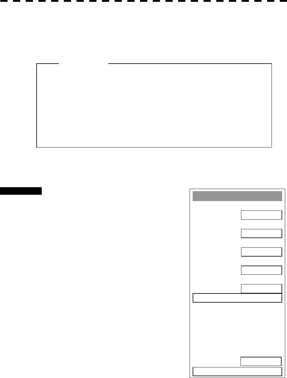
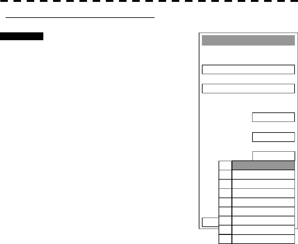
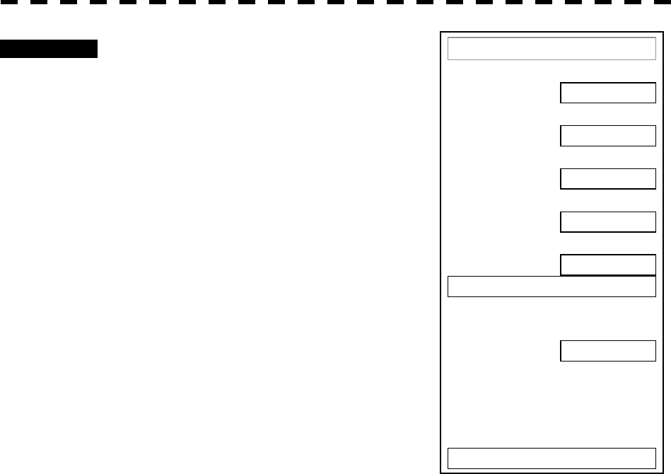
A
TA Settin
g
1. Vector Time
6 min
2. Past Position
OFF
3. CPA Limit
10 nm
4. TCPA Limit
1 min
5. CPA Rin
g
ON
6. Trial >
9. Tar
g
et Number Display
0. EXIT
ON
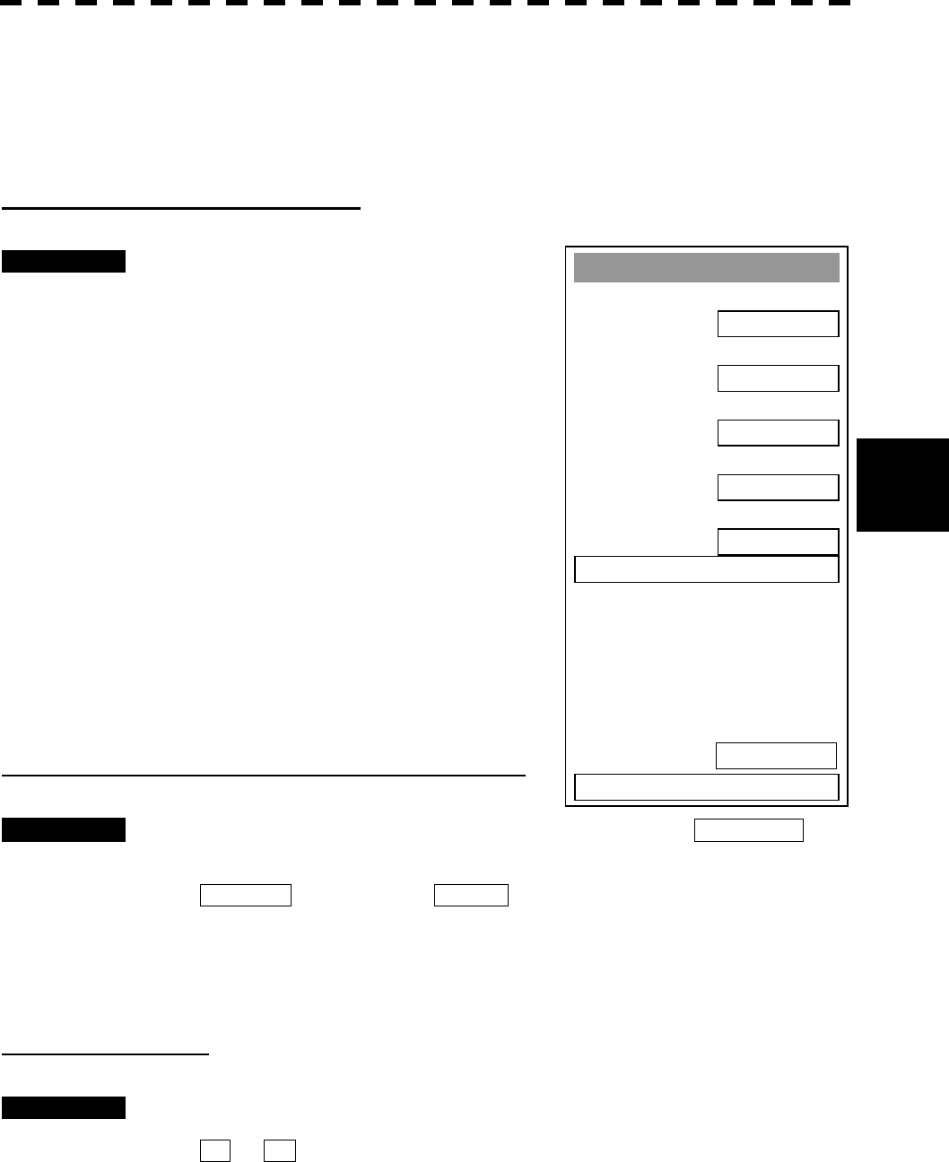
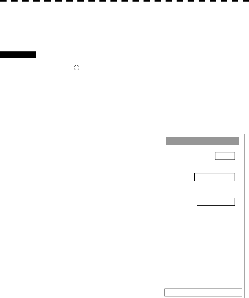
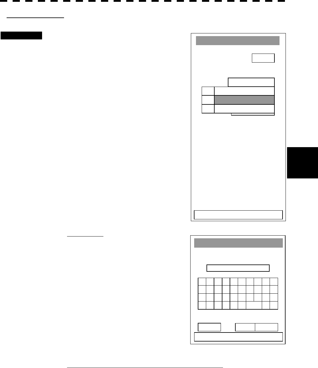
5.1.3 Setting Collision Decision Criteria (CPA/TCPA Limit)
For details on each operation, see 3.4 BASIC OPERATION and 4 MEASUREMENT OF RANGE AND
BEARING.
Set and check collision decision criteria before operating the ARPA system.
Procedures 1 Press [ATA MENU] key.
2 Press [1].
The ATA Setting menu will appear.
3 Press [3].
The ten-key screen will appear.
4 Select the value to be set pressing the
numeric key, and press [ENT].
The selected CPA Limit value will be
determined.
5 Press [4].
The ten-key screen will appear.
6. Select the value to be set pressing the
numeric key, and press [ENT].
The selected TCPA Limit value will be
determined.
l Set the optimum values of collision decision
conditions, depending upon vessel type, water area,
weather and oceanographic conditions.
(For the relations between those conditions and
alarms, refer to section 5.3.6 Alarm Display. )
Attention
5─10
5
5.1 PREPARATION
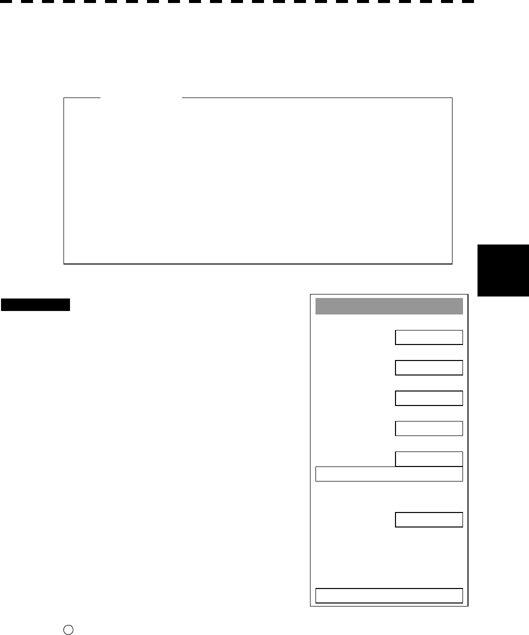
A
TA Settin
g
1. Vector Time
6min
2. Past Position
OFF
3. CPA Limit
10 nm
4. TCPA Limit
1 min
5. CPA Rin
g
ON
6. Trial >
9. Tar
g
et Number Display
0. EXIT
ON
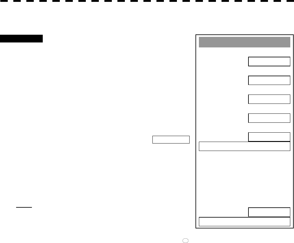
5.1.4 Setting Vectors (Vector Time)
Vector time can be set in minutes in the range 1 to 60 min.
A true (T) vector mode or relative (R) vector mode can be selected.
Setting vector time using the menu
Procedures 1 Press [ATA MENU] key.
2 Press [1].
The ATA Setting menu will appear.
3 Press [1].
The ten-key screen will appear.
4 Select the vector time to be set
pressing the numeric key, and press
[ENT].
The selected vector time will be determined.
Setting vector time using the multi-function control
Procedures 1 Press the [MULTI] control several times to activate the VECTOR
mode.
VECTOR will appear in the MULTI mode field at the lower left of the radar
display.
2 Turn the [MULTI] control to set the vector time.
Setting vector mode
Procedures 1 Press the [VECT] key to select the vector mode.
T or R will appear indicating the vector mode in the ARPA information display
area at the upper right of the radar display.
5─11
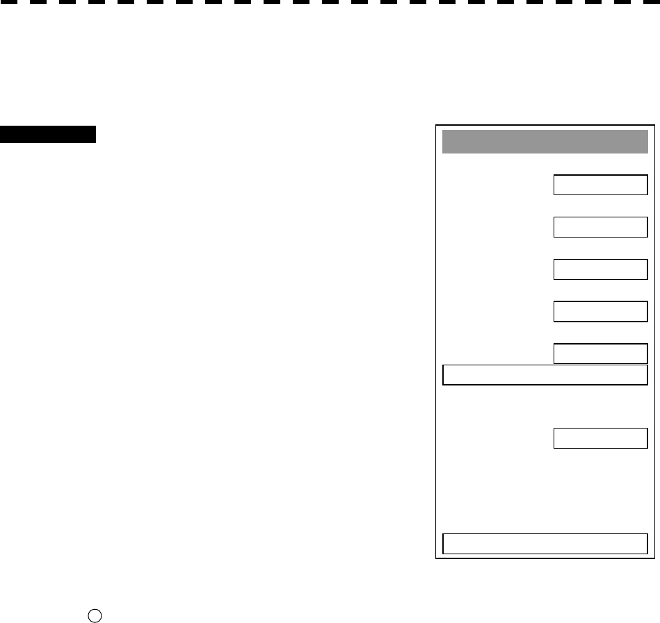
A
TA Settin
g
1. Vector Time
6 min
2. Past Position
OFF
3. CPA Limit
10 nm
4. TCPA Limit
1 min
5. CPA Rin
g
ON
6. TRIAL >
9. Tar
g
et Number Display
0. EXIT
ON
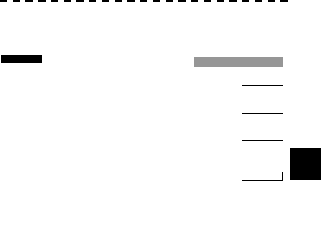
5.1.5 Setting CPA Ring (CPA Ring)
Procedures 1 Press [ATA MENU] key.
2 Press [1].
The ATA Setting menu will appear.
3 Press [5].
The setting of CPA Ring will change between
ON and OFF.
ON: Displays the CPA ring.
OFF: Hides the CPA ring.
While the CPA ring is displayed, CPA RING
is shown at the upper right of the radar display.
While the distance of the specified CPA Limit
value is used as the radius, the CPA ring is
displayed with a red circle of which center is the
own ship’s position.
Note: The CPA ring is not displayed when the true (T) vector mode
is selected.
* The CPA ring switch to Display or Hide within the radar display
21
on page 2-7.
5─12
5
5.1 PREPARATION
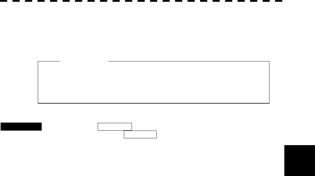
Guard Zone Alarm Key Settin
g
1. Guard Zone 1
ON
2. Guard Zone 2
OFF
0. EXIT
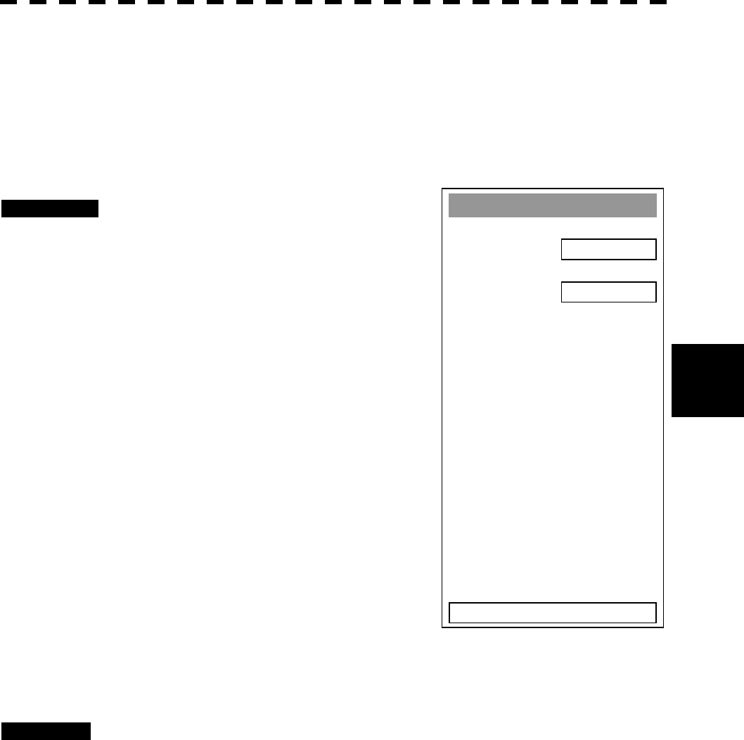
5.1.6 Setting Automatic Acquisition Key Assignment
(GZ Alarm Key Setting)
This section explains how to set a guard zone that is to be assigned to the [GZ ALARM] key.
The setting enables the operator to select ON/OFF for a generally used guard zone by simply operating the
[GZ ALARM] key on the control panel.
Procedures 1 Press [ATA MENU] key.
Press [4].
Press [3].
Press [1].
Guard Zone menu will appear.
ON: Turns on the guard zone when the [GZ
ALARM] key is pressed.
OFF: Does not turn on the guard zone when
the [GZ ALARM] key is pressed.
The same function also as RADAR Alarm (Sector Alarm) can be given.
Procedures 1 Press [ATA MENU] key.
Press [4].
Press [3].
Press [2].
* The setting method is the same as the method of a guard zone.
For the creation method of sector alarm, refer to 3-67P and Chapter 3.5.20 for the creation
method of sector alarm. .

5─13
5.2 EPA OPERATION
This section explains how to use the EPA function.
The EPA function is available when the ATA and ARPA options are not installed.
The EPA function stores/displays vectors as the courses and speeds of target ships.
The data of up to 10 target ships (plot/ID numbers 0-9) can be specified.
The EPA function calculates CPA/TCPA, and issues an alarm.
The data of plotted target ships is erased from memory when the power is turned off.
The EPA function does not display any past plot data.
* The same setting procedure for ATA/ARPA applies to the following settings. See the ATA/ARPA setting
procedure.
1. Vector Time
2. Past Position
3. CPA Limit
4. TCPA Limit
5. CPA Ring
5.2.1 Plotting Targets
Vectors are displayed when a target is plotted twice.
A course and speed are calculated from the two plotting positions, and the plotted target moves in the course at
the speed.
The plot can be modified.
The plot number (target ID number) is not displayed while Display ID Number is set to OFF.
Procedures 1 Move the cross cursor mark onto the target on the radar display, and
press the [ACQ] key to start the first plotting.
2 Enter the plot number (target ID number), pressing the numeric key(s) [0]
to [9].
3 Press [ENT] to finish the first plotting.
The acquisition symbol and plot number will be displayed at the plotting position.
4 When 30 seconds to 15 minutes has passed after the first acquisition,
move the cross cursor mark onto the current target position, and take
steps 1 to 3 to perform the second plotting.
When finishing the second plotting, the system clears the symbol and plot number that
were displayed at the end of the first plotting, and displays the symbol (vector) and plot
number at the second plotting position.
The plotted target (symbol and plot/ID number) moves in a specified course at a specified
speed. The course and speed are calculated from the two plotting positions. At this
time, the CPA and TCPA at positions where the plotted target moves are calculated, and an
alarm is issued when the plotted target goes into the guard zone.

5─14
5.2 EPA OPERATION
5
5.2.2 Modifying Plotted Target Data
The system modifies specified plotted target data.
It clears the specified data, and displays the plotted target immediately before it moves to the clear position
until re-acquiring a target.
Procedures 1 Press the [ACQ] key.
2 Enter the plot number (target ID number) for modification, pressing the
numeric key(s) [0] to [9].
3 Press the [CLR] key.
The previously updated status will be displayed. “M” is also displayed beside the mark,
indicating that modification is in progress.
4 Move the cross cursor mark to the modification position to re-acquire a
target.
At this time, specify the plot number you entered in step 2.
([ACQ], [0]-[9], [ENT])
5.2.3 Canceling Plotted Target Data
The system cancels the display of specified plotted target data.
Once plotted target data is canceled, it cannot be restored any more.
Procedures 1 Press the [ACQ] key.
2 Enter the plot number for cancellation, pressing the numeric key(s) [0] to
[9].
3 Press the [TGT CNCL] key.
The plotted target data of the specified plot number will be canceled.
Canceling all plotted targets
Procedures 1 Hold down the [TGT CNCL] key for 5 seconds or more.
The plotted targets of all the plot numbers will be canceled.

5─15
5.2.4 Displaying Numeric Data of Plotted Targets
The following data is displayed for a specified plotted target:
TGT ID Plot number
BRG Bearing: 0.1° unit
RANGE Range: 0.1 nm unit
COURSE Target’s true course: 0.1° unit
SPEED Target’s true speed: 0.1 knot unit
CPA CPA: 0.1 nm unit
TCPA TCPA: 0.1 min unit
TIME Elapsed time: 0.1 min unit
Procedures 1 Press the [TGT DATA] key.
2 Enter the plot number pressing the numeric keys [0] to [9].
3 Press [ENT] key.
The data of the specified plot number will be displayed.
The mark of the target for which numeric data is displayed is changed into “□”.
5─16
5.2 EPA OPERATION
5
EPA Settin
g
1. Vector Time
6 min
2. Past Position
OFF
3. CPA Limit
10 nm
4. TCPA Limit
1 min
5. CPA Rin
g
ON
6.
A
udible Warnin
g
0. EXIT
ON
5.2.5 Setting EPA Alarm (Audible Warning)
Alarm that may sound during the use of EPA can be set to ON/OFF.
Procedures 1 Press [ATA MENU] key.
Press [1] key.
The EPA Setting menu will appear.
2 Press [6] key.
EPA alarm sound is switched ON or OFF.
ON: Sets the EPA alarm sound to ON.
OFF: Sets the EPA alarm sound to OFF.
Note: When this function turns off and CPA/TCPA alarm occurs, alarm does not sound. Take care for
maneuvering the ship.

5─17
l If untracked targets intrude into the guard zone in the
conditions that maximum number of targets is under
tracking, the targets acquired automatically will be
cancelled in the order of lower levels of danger.
5.3 ATA/ARPA OPERATION
This section explains how to use the ATA and ARPA functions.
Each function is available only when the ATA or ARPA option is installed.
The functions automatically track a target, and store/display vectors as the course and speed.
They calculate CPA and TCPA, and issue an alarm.
The basic operations of ATA and ARPA are the same, but available functions are different.
The ATA function can track up to 30 ships; the ARPA function can track up to 100 ships.
Both functions set a guard zone for automatic acquisition.
The ARPA function permits the use of the trial maneuvering function (TRIAL). (The ATA does not.)
When the power is turned off or the transmit/standby mode is activated, tracking data is erased from memory.
5.3.1 Acquiring Target
Target acquisition can be performed on two modes, AUTO and MANUAL, and both modes can be used at the
same time.
Automatic Acquisition [AUTO]
Procedures 1 Press the [GZ ALARM] key.
Automatic acquisition will be started. The mark “ ” and target ID number are put to
an acquired target, and they move together with the target. The vectors are displayed
within one minute.
2 Press the [GZ ALARM] key again.
Automatic acquisition will be turned off, and the guard zone disappears from the radar
display. However, automatically acquired ships are continuously tracked.
For the guard zone to be called by using the [GZ ALARM] key, refer to Section 5.1.6
Setting Automatic Acquisition Key Assignment.
* The guard zone can be called by using buttons and shown in the radar display on page 2-7.
Attention
49 50
5─18
5.3 ATA/ARPA OPERATION
5
Manual Acquisition [MANUAL]
Procedures 1 Move the cross cursor mark onto the target to be acquired, and press the
[ACQ] key.
The target will be acquired. The initial acquisition mark and target ID number are put to
the acquired target, and the vectors are displayed within one minute.
When using only the manual acquisition mode alone, press the [GZ ALARM] key to turn
off the automatic acquisition mode.
Use of Automatic and Manual Acquisition Modes [ACQ AUTO] / [ACQ MANUAL]
Use the manual acquisition mode while the automatic acquisition mode is on.
Manually acquire the target to which particular attention should be paid, and get the other targets automatically
acquired. If a new target appears exceeding the maximum number of targets, the manually acquired target is
displayed even in the background until it gets out of the display. However, automatically acquired targets are
canceled starting far distance from own ship.
l If more targets are acquired manually in the
condition that the maximum number of targets are
under tracking, the targets under tracking will be
cancelled in the order of lower level of danger in
order to track the manually acquired targets.
Attention
Target manually captured.
The initial capture symbol is displayed.
Target that has intruded the zone for 1 min.
The capture symbol and vector are displayed.

5─19
5.3.2 Canceling Unwanted Targets
Unwanted targets can be canceled one by one in the following cases:
· Tracking is no longer necessary for targets with which vectors/symbols are displayed after being acquired
and tracked.
· The number of vectors on the radar display needs to be reduced for easy observation.
When targets are to be re-acquired from the beginning, all the current vectors can also be canceled.
Canceling targets one by one
Procedures 1 Move the cross cursor mark onto the target to be canceled.
2 Press the [TGT CNCL] key.
The target’s vectors and symbols will disappear, and only the radar video remains.
Canceling all targets collectively
Procedures 1 Hold down the [TGT CNCL] key.
The vectors and symbols of all the targets will disappear, and only the radar videos
remain.
Note: When all the targets have been canceled, the system stops tracking them. Thus, you need to re-acquire
targets in manual or automatic acquisition mode. Do not cancel all the targets unless otherwise
required.

5─20
5.3 ATA/ARPA OPERATION
5
A
TA Settin
g
1. Vector Time
6 min
2. Past Position
OFF
3. CPA Limit
10 nm
4. TCPA Limit
1 min
5. CPA Rin
g
ON
6. Trial >
9. Tar
g
et Number Display
ON
0. EXIT
5.3.3 Displaying Target ID No. (Target Number Display)
A target ID number is a value displayed beside the acquisition symbol when a target is acquired.
ID numbers are assigned to targets in acquisition order. When the ATA function is used, ID numbers 1 to 30
are automatically assigned. When the ARPA function is used, ID numbers 1 to 100 are automatically assigned.
Each target is identified by the assigned ID number until it is lost or its acquisition is canceled.
Procedures 1 Press [ATA MENU] key.
2 Press [1] key.
The ATA Setting menu will appear.
3 Press [9] key.
The Target Number Display is switched ON or
OFF.
ON: Displays target ID numbers.
OFF: Hides target ID numbers.
ARPA TRACK: Displays target ID number
with ARPA track.
If there are many tracking targets and their
symbol display is confusing, set Target Number
Display to OFF to view the radar display easily.
Note: An ID number is always displayed for only targets with which numeric data is displayed.
5─21
5.3.4 ATA/ARPA Data Display
(Refer to Example of Display in page 2-1. )
Display of Vectors
A vector to represent a target’s predicted position can presented in the True vector or Relative vector mode. In
each mode, a vector length can be freely changed for a time interval of 1 to 60 minutes.
The True and Relative vector can be switched by using buttons
47
shown in the radar display on page 2-7.
[I] Vector Mode Selection
True Vector Mode
In the true vector mode, the direction of a target vector indicates the true course of the target and its vector
length is proportional to its speed.
In this mode, own ship’s vector is displayed as shown below.
In this mode, the movements of other ships around own ship can be accurately and easily monitored.
However, no CPA RING can appear in this mode.
l When a target or own ship changes a course, or when
a target is acquired, its vector may not reach a given
level of accuracy until three minutes or more has
passed after such course change or target
acquisition.
Even if three minutes or more has passed, the vector
may include an error depending upon the tracking
conditions.
Attention
Own Ship’s Vector True Vector
The relative vector is not displayed
HL
5─22
5.3 ATA/ARPA OPERATION
5
Relative Vector Mode
In displaying the relative vector of a target, press the [VECT R/T] key to select the Relative Vector mode.
The relative vector does not represent the true motion of the target, but its relative relation with own ship.
This means that a target with its relative vector directed to own ship (passing through the CPA LIMIT ring) will
be a dangerous target. In the Relative Vector mode, it can be seen at a glance where the CPA LIMIT of the
dangerous target is.
Therefore, the TRUE/REL mode shall optionally be used for the purpose of observation: the TRUE vector
mode for grasping the true aspect of a target, and the REL vector mode for grasping a target’s closest point of
approach (CPA)
CPA ring
Relative Vector
The true vector is not displayed
HL
5─23
[II] Vector Length: VECTOR TIME
The vector length of a target is proportional to its speed, and the vector time can be switched in a range of 1 to
60 minutes by used for ten-key.
The diagram below illustrates a vector length of a target for six minutes, and the tip of the vector represents the
target’s position expected to reach six minutes later.
Refer to Section 5.1.4 Setting Vectors for how to change the vector time.
Current Position Future Predicted Position
(6 min later in this example)
HL
5─24
5.3 ATA/ARPA OPERATION
5
A
T
A
Settin
g
1. Vector Time
6 min
2. Past Position
OFF
3. CPA Limit
10 nm
4. TCPA Limit
1 nm
5. CPA Rin
g
ON
6. TRIAL
9. Tar
g
et Number Display
ON
0. EXIT
1. OFF
2. 0.5 min
3. 1 min
4. 2 min
5. 4 min
6. 0.1 nm
7. 0.2 nm
8. 0.5 nm
9. 1 nm
Display of Past Positions [PAST POSN]
Procedures 1 Press [ATA MENU] key.
2 Press [1] key.
The ATA Setting menu will appear.
3 Press [2] key.
The Past Position screen will appear.
4 Select the past position display
interval to be set, pressing the
numeric key.
The selected past position display interval will
be set.
OFF: Hides past positions.
Time/Range: Past positions are displayed at the
set intervals.
The ATA/ARPA Past Position function can display up to 6 past positions of a target. The display interval can
be set to specified time intervals of 0.5, 1, 2, or 4 minutes, or specified range intervals of 0.1, 0.2, 0.5, or 1 nm.
The specified interval is shown on the right of PAST POSN in the ARPA information display area. When OFF
is shown, Past Position is set to OFF in the menu.
Switching between the True and Relative Vector modes takes place
at the same time the vector mode is switched. In relative mode,
target’s relative tracks displayed.
HL
5─25
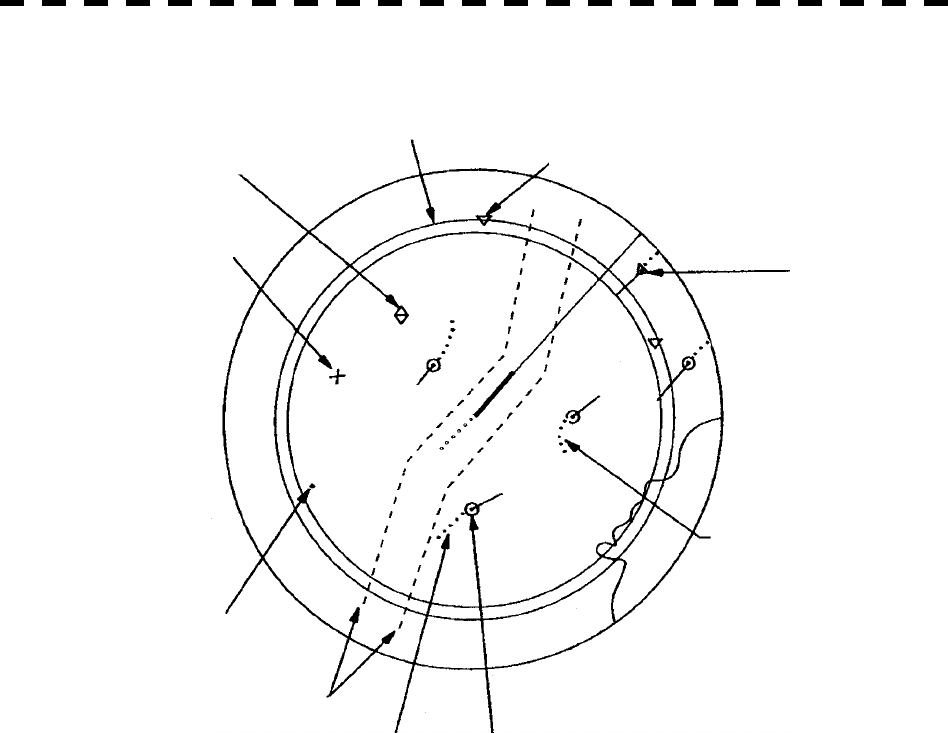
An example of display is shown in Fig. 5-4
Fig. 5-4 Example of Display (in North-up and True Vector mode)
In addition to the marks and symbols shown above, fixed/variable range markers, electronic bearing lines, etc.
are presented on an actual video.
Trackball (Cursor Mark)
Lost Target
Guard Zone
Target intruding the Guard Zone
Dangerous Target
Past Positions
(Changed Course)
Safe Target
Past positions
(Straight Course)
N
AV L i n e s
Untracked Target
HL
5─26
5.3 ATA/ARPA OPERATION
5
5.3.5 Target Data Display
Type of Data Display
Target Data
Target identification (TGT ID) ID number of the target
True bearing: BEARING 0.1° unit
Range: RANGE 0.1 NM unit
True course: COURSE 0.1° unit
True speed: SPEED 0.1 knot unit
Closest point of approach (CPA) 0.1 NM unit
Time to CPA (TCPA) 0.1 min unit
Bow crossing range (BCR) 0.1 NM unit
Bow crossing time (BCT) 0.1 min unit
The target for which its numeric data is displayed is marked with a symbol “ ” to distinguish from other
targets.
If a target’s data is displayed, but without the symbol “ ”, such a target exists outside the currently displayed
radar display.
[I] Method of Displaying Target Data [TGT DATA]
Procedures 1 Move the cross cursor mark onto the target for which numeric data is to
be displayed, and press the [TGT DATA] key.
Then, the data of the designated target will appear, it will be marked with a symbol “ ”.
The target data will remain on the radar display until the target is lost and its vector
disappears, or until another target is designated.
If a target with the mark “ ” is designated, only its true bearing (BEARING) and range
(RANGE) will appear until its vector appears.
* Buttons and on the radar display on page 2-7 are available to switch target numbers of numeric data.
l When a target or own ship changes its course, or when a new
target is acquired, its vector may not reach a given level of
accuracy until three minutes or more has passed after such
course change or target acquisition.
Even if three minutes or more has passed, the vector may
include an error depending upon the. tracking conditions.
Attention
51
52
5─27
A
TA Tar
g
et INFO
1. Name
2. Track Color
T
ar
g
et ID
0. EXIT
[II] Input of target information (ATA Target INFO)
This radar enables name inputs and target track color changes for individual ATA/ARPA targets acquired.
* EPA is not available to make this setting.
Procedures 1 Turn OFF the cursor mode.
Button on the radar display is available to change the cursor mode.
2 Place the cursor over the target and then press [CLR/INFO] key.
The ATA Target INFO screen opens.
* This function is available only when the cursor mode is set to OFF.
Target information screen
Item overview
Target ID: Target ID currently selected.
Name: The name of the target. It is
blanked in the initial status. The
user is to enter a name.
Track Color: Determines a target track color.
19
5─28
5.3 ATA/ARPA OPERATION
5
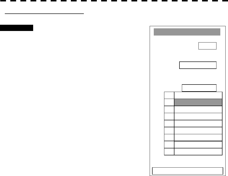
Name entry (Name)
Procedures 1 While the ATA Target INFO screen is
open, press [1] key.
2 For the entry of a new name
® 2. INPUT
For the selection of a name from
names that have already been
entered
® 1. DATA BASE.
For new entry
Selecting INPUT displays the screen shown
below.
After making an entry, place the cursor over
[ENT] key and then press it.
When the name entered with INPUT is
changed to a target name, it is saved in DATA
BASE.
* Up to eight characters can be entered as a
name.
For calling a name from the names that have been entered
Selecting DATA BASE lists INPUT names that have already been entered. From the list,
select a name you want to use.
* Names for 30 ships can be saved in DATA BASE.
1 234 5 6 7 8 90
B CDE F G H I JA
L M N O P Q R S TK
V W X Y Z SP < >U
DEL ENT BS
Name
EXIT
A
TA Tar
g
et INFO
1. Name
2. Track Color
T
ar
g
et ID
0. EXIT
1. DATA BASE
2. INPUT
3. OFF
5─29
1. OFF
2. 1-CYAN
3. 2-WHITE
4. 3-BULE
5. 4-GREEN
6. 5
-
YELLOW
7. 6-RED
8. 7-PIN
K
9. NEXT Pa
g
e
A
TA Tar
g
et INFO
1. Name
2. Track Color
T
ar
g
et ID
0. EXIT
Track Color Setting (Track Color)
Procedures 1 While the ATA Target INFO screen is
open, press [2] key.
2 Pressing numeric key(s), select a
color number you want to set.
Colors selectable with Track Color are colors
that have been set within the ATA Track Setting.
When colors are set, individual colors can be
set for 10 ships. For the 11th to 20th ships, 10
ships are to be set collectively.
On this screen, selection of the 1st track is to
select CYAN.
For target tracks, up to 20 ships can be
displayed.
For color settings selected with Track Color,
see page 5-45 in Section 5.3.9.

5─30
5.3 ATA/ARPA OPERATION
5
5.3.6 Alarm Display
The ATA/ARPA system provides the following alarms:
Dangerous target alarm: CPA/TCPA
Guard zone entry alarm: GZ
Lost target alarm: LOST
System function alarm: ARPA (DATA)
Gyro set alarm: SET GYRO
Dangerous Target Alarm
CAUTION
Since these alarms may include some errors
depending on the target tracking conditions, the
navigation officer himself should make the final
decision for ship operations such as collision
avoidance.
Making the final navigation decision based only on
the alarm may cause accidents such as collisions.
In the ARPA system, targets are categorized into two types: tracked targets and dangerous targets.
The grade of danger can easily be recognized on the display at a glance. So the officer can easily decide
which target he should pay attention to.
The types of target and alarm are shown below.
Dangerous Target Alarm
Status Symbol on display Alarm characters Alarm sound Conditions
Tracking target ¡ (OFF) (OFF)
· CPA>CPA LIMIT
· 0>TCPA
· TCPA>TCPA LIMIT
Dangerous target TCP/TCPA Beep sound (pee-poh)
Acknowledgeable
· CPA£CPA LIMIT,
0£TCPA£TCPA LIMIT
CPA LIMIT and TCPA LIMIT: The Setting Values
5─31
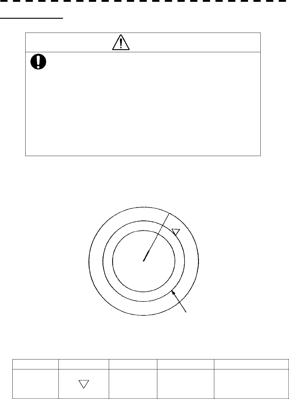
Guard Zone Alarm
CAUTION
In setting a guard zone, it is necessary to adjust
the gain, sea clutter suppression and rain/snow
clutter suppression to ensure that target echoes
are displayed in the optimum conditions. No
guard zone alarms will be issued for targets
undetected by the radar, and this may cause
accidents such as collisions.
The guard zone functions are to set a zone at an arbitrary range and to deliver an alarm if any target intrudes
within this zone.
For the method of setting a guard zone, refer to page 3-60, section 3.5.19 Set Guard Zones.
Guard Zone Alarm
Status Symbol on display Alarm characters Alarm sound Conditions
Target entering
the guard zone GZ Beep sound (pipipi)
Acknowledgeable
An alarm sound is generated
while a target has entered into
the range of 0.5 NM between
the outer and the inner ring.
Guard Zone
HL
5─32
5.3 ATA/ARPA OPERATION
5
Lost Target Alarm
When it is impossible to continue tracking any acquired and tracked target, the LOST target alarm will be
generated. The typical causes for alarm generation are shown below, but not limited to the following:
· The target echo is very weak.
· The target is shadowed by a shore or a large ship and its echo is not received.
· The target echo is blurred by sea clutter returns.
Lost Target Alarm
Status Symbol on display Alarm characters Alarm sound Conditions
Lost target
LOST Beep sound (pee)
Acknowledgeable
The alarm will sound once
when a lost target symbol is
displayed.
l If the gain, sea clutter suppression, rain/snow clutter
suppression are not adjusted adequately, the lost
target alarm may be easily generated. So such
adjustments should be mad carefully.
Attention
Lost Target
HL
5─33
System Function Alarm
When an abnormal state of an input signal or a trouble in the processing circuitry occurs, an character or alarm
is generated. When an alarm occurs against any ARPA function, ARPA (DATA) will appear in the WARNING
display area, but no indication is made in the ARPA information display. This status means that there is any
operational trouble in the ARPA system. Please, contact the service depot or the manufactures.
System Function Alarm
Alarm characters Alarm sound Conditions
ARPA(DATA) Beep sound (pipipi) An alarm sound is generated when an ARPA circuit error
occurs.
Gyro Set Alarm
The North Stabilizing Kit (NSK) in this system receives signals from a gyro. Even if the power is turned off,
the system will follow up the gyro. However, the system stops the follow-up operation when the power of the
master gyro is turned off or when any trouble occurs to the line. When the power of the master gyro is
recovered, the SET GYRO alarm will be generated.
If this alarm occurs, set the gyro.
Gyro Set Alarm
Alarm characters Alarm sound Conditions
SET GYRO Beep sound (pipipi) The signals from the gyro are stopped, but the gyro is
recovered.

5─34
5.3 ATA/ARPA OPERATION
5
5.3.7 Trial Maneuvering (Trial)
Attention: Trial maneuvering can be done only when the ARPA option is installed. Trial maneuvering is
unavailable if the ATA option is installed.
The trial maneuvering is the function of simulating own ship’s course and speed for collision avoidance when a
dangerous target appears. When manually entering own ship’s course and speed against the data of the
acquired target, it is checked whether the situation is dangerous or not.
The ranges of course and speed to be entered manually:
Course: 360° (in 0.1° intervals)........................................................................... [EBL] control
Velocity: 0 to 100 knots (in 0.1 knot steps)........................................................... [VRM] control
l Trial maneuvering is to simulate own ship’s course
and speed in the conditions that the course and
speed of a target ship are unchanged as they are.
As the situation is different from any actual ship
maneuvering, set values with large margins to CPA
Limit and TCPA Limit.
Attention
5─35
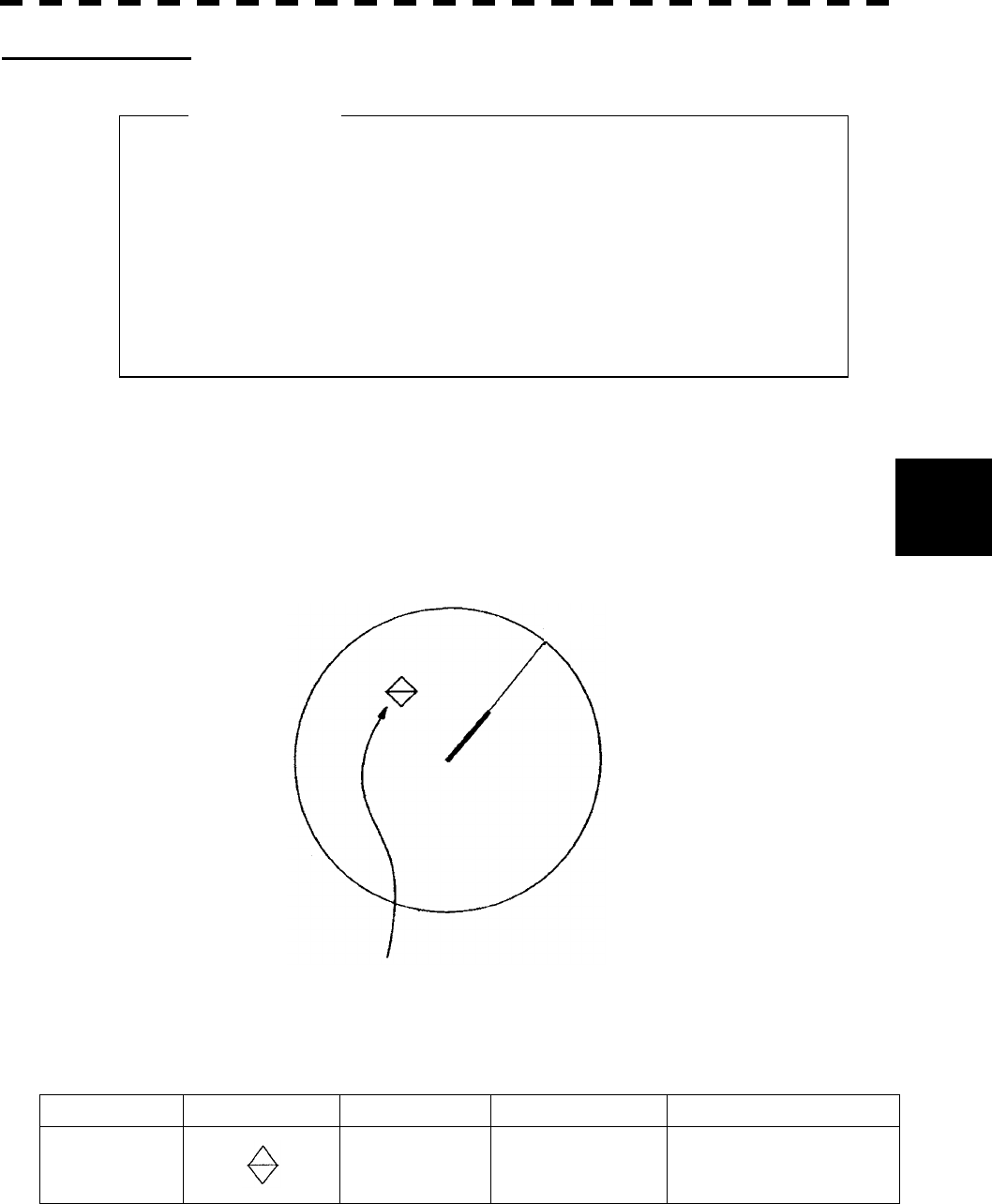
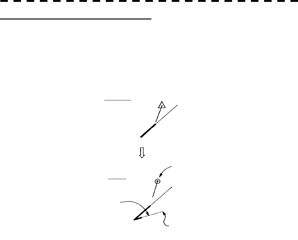
Trial Maneuvering in the True Vector Mode
In the True Vector mode, calculations are performed according to the values set by Trial Speed and Trial Course,
and the result is displayed as a bold-line that represents the change of own ship’s vector as shown in the figure
below (an example of the course changed to the right).
In this figure, the dangerous target forward right becomes safe as a result of simulation.
The target data display field indicates the current CPA LIMIT and TCPA LIMIT values regardless of the result
of simulation.
Dangerous target
Own ship
Change of symbol as a result of trial maneuver
Change in course
Trial Speed (vector time)
Own ship
HL
HL
TRIAL
N
ORMAL
T
5─36
5.3 ATA/ARPA OPERATION
5
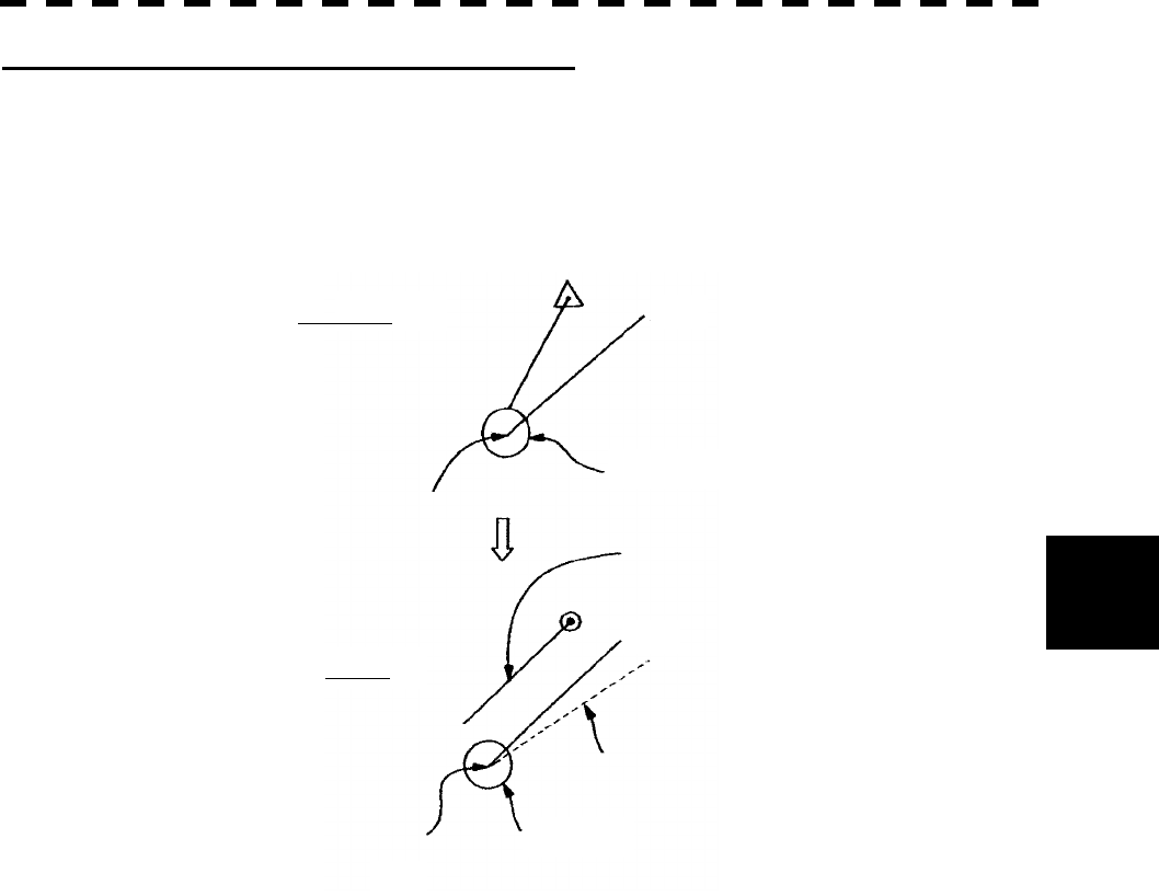
Trial Maneuvering in the Relative Vector Mode
The result of Trial maneuvering in the Relative Vector mode is shown by a change in target vector. In the
figure below (in the same conditions as in the True Vector mode in the previous page), it is seen that the
acquired target is a dangerous one because its vector is crossing the CPA RING.
The above figure shows that the relative vector of the target has changed as shown in the figure as a result of
simulation (course and speed), so that the target’s symbol is changed into “¡”, a safe target.
The data display field indicates the current values of CPA LIMIT and TCPA LIMIT, not those as the result of
simulation, same as in the True Vector mode.
The course change of own ship is displayed as a dotted-lime.
Dangerous target
Own ship
Change of symbol as a result of Trial maneuver
Change in course
Own ship
HL
HL
TRIAL
N
ORMAL
T
CPA RING
CPA RING
5─37
Trial
1. Trial
OFF
2. Course
000.0°
3. Speed
20.0 kts
0. EXIT
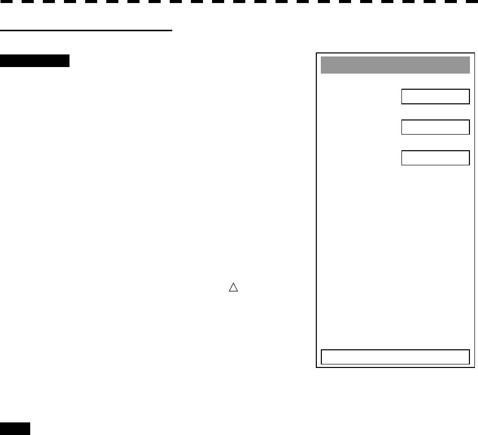
Executing the TRIAL Function
Procedures 1 Press [ATA MENU] key.
2 Press [1] key.
3 Press [6] key.
The TRIAL Menu will appear.
4 Press [1] key.
“Trial” will be set to “ON” and a character “T”
blinks under own ship’s mark on display to
indicate the trial maneuvering mode.
5 Set a course by rotating the [EBL]
control and a speed by rotating the
[VRM] control.
6 As the symbol of plot data, dangerous
target is marked with “ ” and a safe
target with “¡“.
Exit 1 Press [1] key.
“Trial” will be set to “OFF” and the normal display will be restored.
5─38
5.3 ATA/ARPA OPERATION
5
5.3.8 ATA/ARPA Simulation
CAUTION
Simulation is a function to check whether the
ATA/ARPA system is operating normally. Do not
use this function except when checking the
ATA/ARPA operation.
In particular, if this mode is used during
navigation, pseudo targets appear on the radar
display, which may be confused with the actual
targets. Do not use this mode during navigation.
Otherwise, this may cause accidents.
The following simulation to be used for ATA/ARPA can be referred to and modified:
[I] Test Video: Test video for use in checking the operation of the target detection circuit.
[II] ATA Simulator: Pseudo targets are generated on the radar display to check whether the ARPA
functions are operating normally.
[III] Status: Displays the ATA status.
[IV] Gate Display: Gate size to acquire and track targets.
5─39
A
TA TEST MENU
1. Test Video
OFF
2. ATA Simulator
OFF
3. Status
4. Gate Display
OFF
0. EXIT
OFF1.
V
DG2.
V
DH3.
V
DL4.
V
DIN5.
[I] Test Video
Test Video is used to check whether the video signals under target acquisition and tracking are inputted to and
processed in the target processing circuit normally.
However, it is sufficient to check that VDH in TEST VIDEO is displayed.
The start of the Test Video mode is available only in the Standby mode.
Procedures 1 Press [STBY] key.
The equipment will enter the standby state.
2 Press [ATA MENU] key.
Press [5] key.
The ATA Test Menu will appear.
3 Press [1] key.
The Test Video setting screen will appear.
4 Press a numeric key to select a video
signal you want to set.
The selected test video will be set.
The test video is displayed in the background of
the radar display.
In general, VDH is sufficient for target
display checks in test video mode.
If any target displayed clearly in the radar display is not displayed in the Test Video mode, the target detection
circuit of the ARPA system may have a trouble.
l TEST VIDEO may not appear for targets that are not
acquired nor tracked, or if the [GAIN] and [SEA]
controls are adjusted properly
Attention
5─40
5.3 ATA/ARPA OPERATION
5
A
TA TEST MENU
1. TEST Video
OFF
2. ATA Simulator
OFF
3. Status
4. Gate Display
OFF
0. EXIT
OFF1.
SCENARIO12.
SCENARIO23.
SCENARIO34.
SCENARIO45.
SCENARIO56.
SCENARIO67.
[II] ATA Simulator
Pseudo targets can be generated in certain known positions to check whether the ARPA processing circuits are
operating normally. Since the pseudo targets move depending on known parameters, the values for these
pseudo targets can be compared with the known value if the pseudo targets are acquired and tracked, and
displayed. Thus, it can be checked if the ARPA system is operating normally.
Procedures 1 Press the [STBY] key.
The equipment will enter the standby state.
2 Press [ATA MENU] key.
Press [5] key.
The ATA Test Menu will appear.
3 Press [2] key.
The ATA Simulator screen will appear.
4 Select the simulator to be set,
pressing the numeric key.
The selected simulator will be set.
5 Press the [TX/PRF] key.
The simulator will be activated and generate
pseudo targets. The characters "XX" at the
bottom of the radar display blinks indicating
that the simulation mode is active.
ARPA simulator/scenario
TARGET START POINT TARGET END POINT
SCENARIO DISTANCE BEARING DISTANCE BEARING TARGET SPEED
1 3.2NM
10° 1NM 90° 20kts
2 6NM
0° 0NM 0° 10kts
3 6NM
every 18° 1NM every 18° 10kts
4 6NM
45° 1NM 45° 105kts
5 6NM
45° 6NM 150° 20kts
6 6NM
45° 6NM 150° 20kts
Note: When the range between own ship and the pseudo target is 0, the target will disappear.

5─41
Exit 1 Press the [STBY] key.
The equipment will enter the standby state.
2 Press [2] key while the ATA Test Menu is open.
The ATA Simulator screen will appear.
3 Press [1] key to select OFF.
The ATA Simulator is turned off.
5─42
5.3 ATA/ARPA OPERATION
5
Status
* Constant 5
* Video Level TD
* Video Level HI
* Video Level Low
* Gate Size
* Trackin
g
0. EXIT
15
8
1
NARROW
1
[III] Status
The current ATA/ARPA status will appear.
Procedures 1 Press [ATA MENU] key.
The ATA Menu will appear
Press [5] key.
The ATA Test Menu will appear.
2 Press [3] key.
The Status screen will appear..
*Constant: Vector response
*Video Level TD: Threshold value used for
tracking
*Video Level HI: VD threshold value used
for guard zone
*Video Level Low: Unused
*Gate Size: Size of gate used for
tracking
*Tracking: Number of targets
currently acquired
5─43
A
TA TEST MENU
1. TEST Video
OFF
2. ATA Simulator
OFF
3. Status
4. Gate Display
OFF
0. EXIT
[IV] Gate Display
The gate displays an area monitoring a target using the ATA/ARPA function. This radar equipment allows the
gate size to change automatically according to target distance and size. User can check the gate size using the
following function.
Procedures 1 Press [ATA MENU] key.
Press [5] key.
The ATA Test Menu will appear.
2 Press [4] key.
The gate display mode is switched.
ON: Gate is displayed
OFF: Gate is not displayed
3 The gate displays data of a target you
want to check using the cursor and
[TGT DATA] key. (See Section 5.3.5
Target Data Display.)
The data is displayed, and the gate is displayed
around the ATA/ARPA symbol in green.
Note: The ATA/ARPA function can display the gate of two targets
simultaneously.
ARPA/ATA symbol Vector
Echo Gate (displayed in green)
5─44
5.3 ATA/ARPA OPERATION
5
A
TA Track Settin
g
1. Track Function
ON
2. Track Color >
3. Track Display >
4. Track Memory Interval
3 sec
5. Clear Track Color
WHITE
6. Clear Track Number
7. Card2 Track Display
0000
0. EXIT
WHITE
5.3.9 Setting ATA/ARPA Tracks (ATA Track Setting)
Track information on acquired ATA/ARPA targets can be set.
This radar can acquire target tracks of up to 20 ships.
[I] Turning ON/OFF the target track function (Track Function)
Procedures 1 Press [ATA MENU] key.
2 Press [3] key.
The ATA Track Setting Menu will appear.
3 Press [1] key.
The ATA/ARPA Track function is switched
between ON and OFF.
ON: Sets the ATA/ARPA Track function to
ON.
OFF: Sets the ATA/ARPA Track function to
OFF.
* When this function turn off, all target track functions to OFF(Including track memory), If so, checking
cannot be done later.
5─45
Track Color
1. All
2. ATA Track No.1
3. ATA Track No.2
4. ATA Track No.3
PIN
K
5. ATA Track No.4
RED
6. ATA Track No.5
7. ATA Track No.6
OFF
0. EXIT
WHITE
8. ATA Track No.7
9. NEXT
INDIVIDUA
L
YELLOW
GREEN
CYAN
1. INDIVIDUAL
2. WHITE
3. CYAN
4. BLUE
5. GREEN
6.
Y
ELLOW
7. PIN
K
8. RED
9. NEXT
[II] Setting target track colors (Track Color)
The same color can be selected for all target tracks, or different colors can be set to ships whose track numbers
are 1 to 10. In such cases, 10 ships, whose track numbers are 11 to 20, are to be set collectively.
Procedures 1 Press [2] key while the ATA Track
Setting Menu is open.
Track color can be set.
2 Press [1] key.
Which is to be selected, setting individual colors
or setting the same color for all ships, is to be
determined depending on the setting for the ALL
item.
Setting individual colors: Select INDIVIDUAL
Setting the same color for all ships:
Select a color number
For setting individual colors
Selecting INDIVIDUAL makes it effective to set track numbers
from ATA Track No.1 to ATA Track No.10 as well as individual
settings for Other. Set a color for each target.
When pressing the item number of the target to be set displays a
list of colors, select desired colors from the list.
Eight colors are selectable: OFF, WHITE, CYAN, BLUE,
GREEN, YELLOW, PINK and RED.
ATA Track No.1 to
ATA Track No.10: 1st ship to 10th ship
Other: 11th ship to 20th ship
Settings are made as shown above.
* Note that individual settings are effective only when INDIVIDUAL has been set.
For setting the same color for all ships
This setting is determined when you select a color displayed with ALL selected. The types of colors are
the same as those to be used for setting individual colors.
5─46
5.3 ATA/ARPA OPERATION
5
Track Display
1. All
2. ATA Track No.1
3. ATA Track No.2
4. ATA Track No.3
ON
5. ATA Track No.4
ON
6. ATA Track No.5
7. ATA Track No.6
ON
0. EXIT
ON
8. ATA Track No.6
ON
9. NEXT
ON
ON
INDIVIDUA
L
1. INDIVIDUAL
2. ON
3. OFF
[III] Setting Display of Target Tracks (Track Display)
The display of target tracks can be set to ON/OFF. For the display of tracks, setting for display/nondisplay of
all ships or for individual ships can be made.
Procedures 1 Press [3] key while the ATA Track
Setting Menu is open.
Track display can be set.
2 Press [1] key.
Which is to be selected, setting individual
tracks or display/nondisplay for all ships, is to
be determined depending on the setting for the
ALL item.
Setting individual tracks: Select INDIVIDUAL
Setting display for all ships: Select ON
Setting nondisplay for all ships: Select OFF
For setting individual tracks
Selecting INDIVIDUAL makes it effective to set track numbers
from ATA Track No.1 to ATA Track No.10 as well as individual
settings for Other. Select display/nondisplay for each target.
Each time ON/OFF window is pressed, a decision branch is
switched to another.
ATA Track No.1 to
ATA Track No.10: 1st ship to 10th ship
Other: 11th ship to 20th ship
Settings are made as shown above.
* Note that individual settings are effective only when INDIVIDUAL has been set.
5─47
A
TA Track Settin
g
1. Track Function
2. Track Color >
3. Track Display >
4. Track Memory Interval
3 sec
5. Clear Track Color
WHITE
6. Clear Track Number
7. Card2 Track Display
0000
0. EXIT
0000
1. OFF
2. 3 sec
3. 5 sec
4. 10 sec
5. 30 sec
6. 1 min
7. 3 min
8. 5 min
9. NEXT
[IV] Setting target track memory intervals (Track Memory Interval)
Target track memory intervals can be set.
* Note that this function is available only when the Target Track function is set to ON.
Procedures 1 Press [4] key while the ATA Track
Setting Menu is open.
The Track Memory Interval setting items are
displayed.
2 Select a number for a memory interval
you want to set.
Settable intervals
Select from the following intervals:
OFF, 3 sec, 5 sec, 10 sec, 30 sec, 1 min, 3 min, 5
min, 10 min, 30 min, 60 min, 1 nm, 3 nm, 5 nm
and 10 nm
* Setting this function to ON saves target tracks
even though Target Display is set to OFF.
5─48
5.3 ATA/ARPA OPERATION
5
A
TA Track Settin
g
1. Track Function
2. Track Color >
3. Track Display >
4. Track Memory Interval
3 sec
5. Clear Track Color
6. Clear Track Number
7. Card2 Track Display
0000
0. EXIT
WHITE
WHITE
1.
A
LL
2. WHITE
3. CYAN
4. BLUE
5. GREEN
6.
Y
ELLOW
7. PIN
K
8. RED
9. NEXT
[IV] Erasing target tracks (Clear Track)
Target tracks can be erased. You can select an erasing method by color setting or an erasing method by track
number setting.
Erasing tracks by color setting (Clear Track Color)
Procedures 1 Press [5] key while the ATA Track
Setting Menu is open.
2 Select the number of the color you
want to erase.
5─49
A
TA Track Settin
g
1. Track Function
2. Track Color >
3. Track Display >
4. Track Memory Interval
3 sec
5. Clear Track Color
6. Clear Track Number
7. Card2 Track Display
0000
0. EXIT
WHITE
1
1.
A
LL
2.
A
TA Track No.1
3.
A
TA Track No.2
4.
A
TA Track No.3
5.
A
TA Track No.4
6.
A
TA Track No.5
7.
A
TA Track No.6
8.
A
TA Track No.7
9. NEXT Pa
g
e
Erasing tracks by track number (Clear Track Number)
Procedures 1 Press [6] key while the ATA Track
Setting Menu is open.
2 Select the track number you want to
erase.
5─50
5.3 ATA/ARPA OPERATION
5
A
TA Track Settin
g
1. Track Function
2. Track Color >
3. Track Display >
4. Track Memory Interval
3 sec
5. Clear Track Color
6. Clear Track Number
7. Card2 Track Display
0000
0. EXIT
WHITE
1
[V] Reading target track saved in CARD2 (Card2 Track Display)
Saved target tracks can be read from CARD2.
Reading targets by color setting
Procedures 1 Press [7] key while the ATA Track
Setting Menu is open.
2 Enter the number you want to read
with the numeric key, and then press
the ENT key.
* For how to save targets in CARD2, see page 3-131, section 3.12.1.

5─51
5.4 AIS OPERATION
* Use of this function requires AIS I/F (option).
There are the following limitations on use of the AIS function,
system, and operation:
[I] This system can display a maximum of 50 AIS targets. There
are two types of filters for increasing the display priority.
(Refer to Section 5.4.6 AIS FILTER SETTING.)
[II] Keep in mind that the following restrictions are placed on use
of the AIS function:
1) The AIS function cannot be turned on in the following cases:
· MANUAL is selected for the speed sensor.
· LOG or 2-axis LOG is used for the speed sensor, and SET
and DRIFT are selected.
2) LOG or 2-axis LOG cannot be selected for the speed sensor in
the following case:
· SET or DRIFT is set while the AIS function is on.
3) MANUAL cannot be selected for the speed sensor in the
following case:
· The AIS function is on.
4) SET/DRIFT (current offset) cannot be turned on in the following
case:
· The AIS function is turned on, and LOG or 2-axis LOG is
selected for the speed sensor.
Attention

5─52
5.4
A
IS OPERATION
5
5.4.1 Initial Setting
This section explains the initial setting for using the AIS function.
Setting the GPS antenna location
Set the GPS antenna location. Set offset ranges in longitudinal direction and latitudinal direction from the
own ship's reference position.
For the setting procedure, refer to Section 8.5 ADJUSTMENT.
Setting collision decision criteria (CPA Limit/TCPA Limit)
The collision decision criteria for the ATA/ARPA function are applied to the AIS function.
For the setting procedure, refer to Section 5.1.3 Setting Collision Decision Criteria.
The AIS setting menu is also available for the collision decision criteria. Note that the same collision decision
criteria must apply to ATA and ARPA.
l If offset ranges are not set correctly, AIS symbols and
radar echoes may be displayed shifted.
l When offset ranges are set, latitude and longitude
data received from the GPS is offset, and the offset
data is displayed as the latitude and longitude of own
ship’s position.
Attention
l Set the optimum values of collision decision
conditions, depending upon vessel type, water area,
weather, and oceanographic conditions.
Attention
5─53
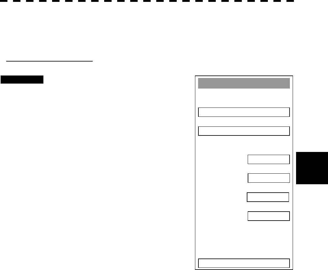
A
IS Settin
g
1. AIS Function
OFF
2. AIS Symbol Display
OFF
3. ATA Symbol Display
ON
4. CPA Limit
1 nm
5. TCPA Limit
1 min
6. AIS Filter Settin
g
>
7. Identical Distance
100 m
0. EXIT
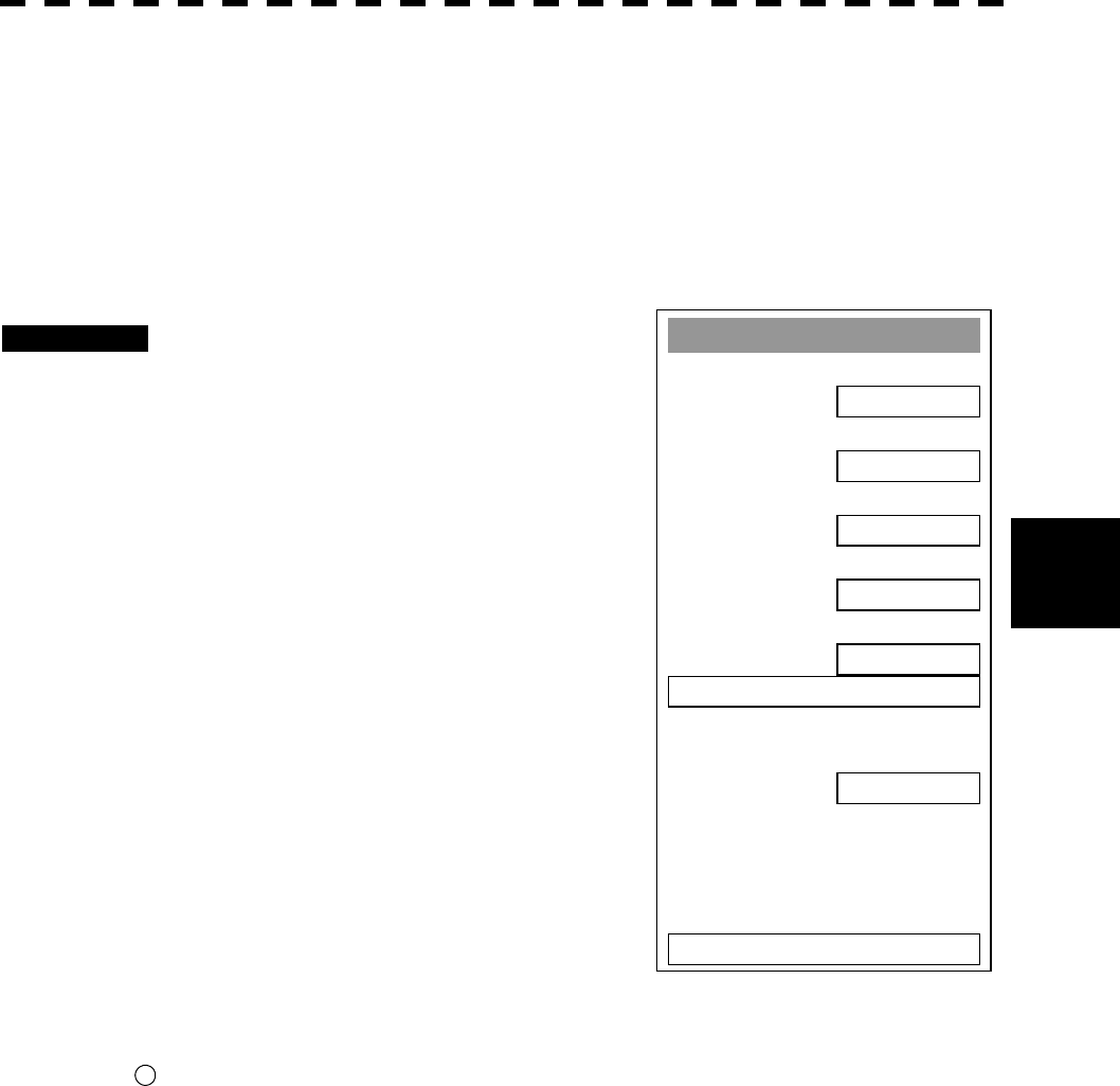
Procedures 1 Press [ATA MENU] key.
2 Press [2] key.
The AIS Setting Menu will appear.
3 Press [4] key.
The ten-key screen will appear.
4 Using numeric keys, enter the CPA
value you want to set, and then press
[ENT] key.
The entered CPA Limit value is determined.
5 Press [5] key.
The ten-key screen will appear.
6 Using numeric keys, enter the TCPA
value you want to set, and then press
[ENT] key.
The entered TCPA Limit value is determined.
* The collision decision criteria set on the AIS side are also available on ATA/ARPA.
5─54
5.4
A
IS OPERATION
5
5.4.2 Setting AIS Display Function (AIS Function)
Switch the AIS symbol display function to ON/OFF.
Procedures 1 Press [ATA MENU] key.
Press [2] key.
The AIS Setting menu will appear.
2 Press [1] key.
The AIS Function is switched between ON and
OFF.
ON: Enables the AIS display function.
OFF: Disables the AIS display function.
* Button on the radar display on page 2-7 is also available to switch the display functions.
* Note that turning OFF this function switches all AIS display functions to OFF.
l When the AIS display function is set to OFF, no AIS
symbols are displayed.
l The AIS display function itself is turned OFF.
l Once the AIS display function is set to OFF, it is not
automatically switched to ON even if a dangerous
target exists.
Attention
A
IS Settin
g
1. AIS Function
OFF
2. AIS Symbol Display
OFF
3. ATA Symbol Display
ON
4. CPA Limit
1 nm
5. TCPA Limit
1 min
6. AIS Filter Settin
g
>
7. Identical Distance
100 m
0. EXIT
25

5─55
5.4.3 Activating AIS Targets
Activate an AIS target, and display the target’s vector and make a collision decision.
Manual activation
Activate an AIS target*1 in manual mode to display the vector and HL.
Procedures 1 Press the CURSOR button at the upper right of the radar display
several times until ACT AIS appears.
The cursor mode is set to the AIS activation mode.
2 Move the cross cursor mark onto the inactive AIS target that is to be
activated*1, and press [ENT] key.
The selected AIS target will be activated*1.
Automatic activation
Activate an AIS target in automatic mode to display the vector and HL.
If the guard zone function is in use, an AIS target is activated automatically when it has entered the guard zone.
Dangerous targets are also activated automatically.
The guard zone is the same as for ATA/ARPA. For the setting procedure, refer to “Setting Guard Zone” in 3.4
BASIC OPERATION of the instruction manual.
Reference If an AIS target is activated but the vector is not displayed, refer to Section 5.4.5 Setting AIS
Symbol Display.
*1 For activation of targets, refer to Section 5.1.2 Definitions of Symbols.
5─56
5.4
A
IS OPERATION
5
l The operation above is effective only for active
targets.
5.4.4 Deactivating AIS Targets
Deactivate an AIS target*2 and clear the display of the vector and HL.
Procedures 1 Press the CURSOR button at the upper right of the radar display
several times until CANCEL appears.
The cursor mode is set to the deactivation mode.
2 Move the cross cursor mark onto the active AIS target that is to be
deactivated*2, and press [ENT] key.
The selected AIS target will be deactivated*2 .
*2 For deactivation of targets, refer to Section 5.1.2 DEFINITIONS OF SYMBOLS.
Attention
5─57
5.4.5 Setting AIS Symbol Display Function (AIS Symbol Display)
Switch ON or OFF to set the AIS symbol display function.
Procedures 1 Press [ATA MENU] key.
Press [2] key.
The AIS Setting menu will appear.
2 Press [2] key.
The AIS Symbol Display is switched between
ON and OFF.
ON: Enables the AIS symbol display
function.
OFF: Disables the AIS symbol display
function.
* Button on the radar display on page 2-7 is also available for switching.
A
IS Settin
g
1. AIS Function
OFF
2. AIS Symbol Display
OFF
3. ATA Symbol Display
ON
4. CPA Limit
1 nm
5. TCPA Limit
1 min
6. AIS Filter Settin
g
>
7. Identical Distance
100 m
0. EXIT
26
5─58
5.4
A
IS OPERATION
5
5.4.6 Displaying Numeric Data of AIS Targets
Display the numeric data of active AIS targets.
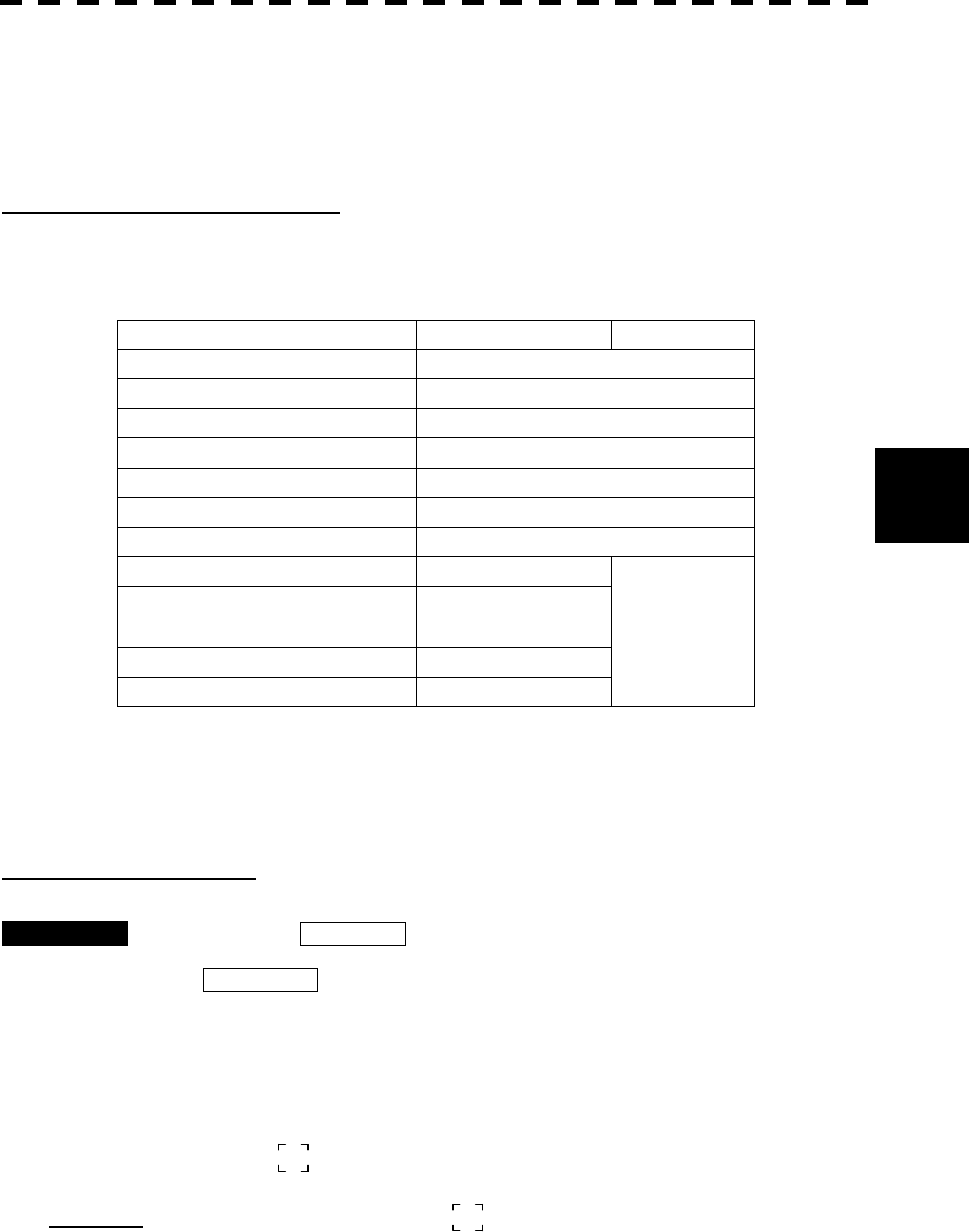
Types of numeric data displayed
There are two modes (simple and detail) to display the numeric data of AIS targets. The display items are
different between the two modes.
Display Item Detail mode Simple mode
NAME (ship name) Up to 20 characters
CALL SIGN Up to 7 characters
MMSI Up to 9 characters
COG (course over ground) 0.1° unit
SOG (speed over ground) 0.1 knot unit
CPA (closest point of approach) 0.1 nm unit
TCPA (time to CPA) 0.1 min unit
BRG (true bearing) 0.1° unit
RANGE 0.1 nm unit
HDG (heading bearing) 0.1° unit
ROT (course change speed) 0.1°/min
L/L (latitude/longitude) 0.001’ unit
Not displayed
The detail mode displays the numeric data of only a single ship; the simple mode can display the numeric data
of up to three ships.
Displaying numeric data
Procedures 1 Press the CURSOR button at the upper right of the radar display
several times until
TGT DATA appears.
The cursor mode is set to the numeric data display mode.
2 Move the cross cursor mark onto the active AIS target for which numeric
data is to be displayed, and press [ENT] key.
The values of the selected AIS target will appear on the right side of the radar display.
The mark is displayed around the symbol.
Reference: If the values are displayed but the mark . is not on the radar display, the target is outside the
radar display.
5─59
Clearing numeric data
Procedures 1 Press the CURSOR button at the upper right of the radar display
several times until TGT DATA appears.
The cursor mode is set to the numeric data display mode.
2 Move the cross cursor mark onto the active AIS target for which numeric
data is to be cleared, and press [CLR] key.
The values of the selected AIS target will be cleared from the right side of the radar
display, and the mark displayed around the symbol will also disappear.
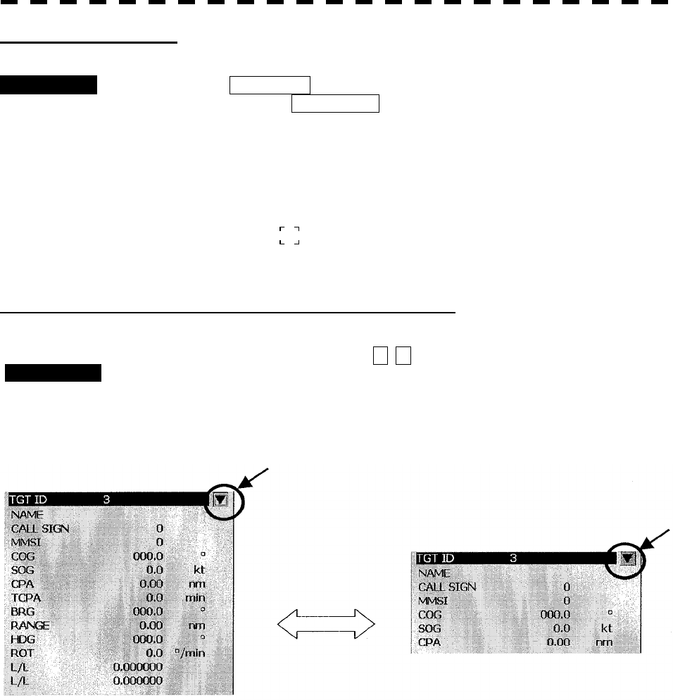
Selecting the detail/simple mode to display numeric data
1 Move the pointer to the button W, W at the upper right of the AIS target’s
numeric data display area, and press [ENT] key.
2 The detail mode or the simple mode is switched each time the button is
clicked.
Switched each time
the button is clicked
Display sample in detail mode Display sample in simple mode
Procedures
5─60
5.4
A
IS OPERATION
5
5.4.7 Setting ATA/ARPA Symbol Display Function
(ATA Symbol Display)
Set the ATA/ARPA symbol display function to ON/OFF.
This function is effective only when the AIS display function (option) is set to ON.
This function is unavailable when the AIS display function is set to OFF.
This function holds data even though the ATA/ARPA display is set to OFF.
For the AIS display function, see Section 5.4.2 on page 5-54.
Procedures 1 Press [ATA MENU] key.
Press [2] key.
The AIS Setting menu will appear.
2 Press [3] key.
The ATA/ARPA Symbol Display Function is
switched ON or OFF.
ON Enables the ATA/ARPA symbol display
function.
OFF: Disables the ATA/ARPA symbol display
function.
* Button on the radar display on page 2-7 is also available to switch between ON and OFF.
A
IS Settin
g
1. AIS Function
OFF
2. AIS Symbol Display
OFF
3. ATA Symbol Display
ON
4. CPA Limit
1 nm
5. TCPA Limit
1 min
6. AIS Filter Settin
g
>
7. Identical Distance
100 m
0. EXIT
27
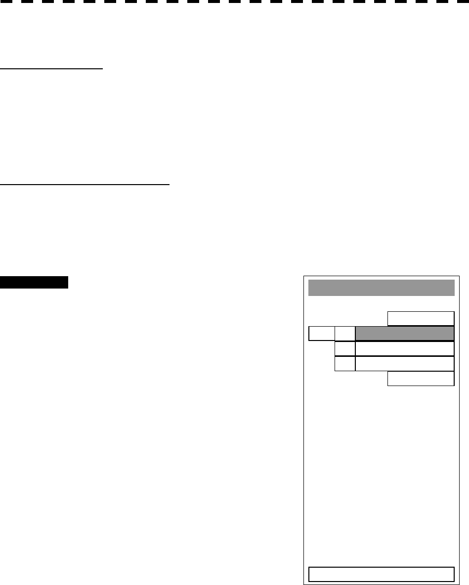
5─61
5.4.8 Setting AIS Filter (AIS Filter Setting)
About an AIS filter
The setting of an AIS filter enables the priority display of AIS targets in the area. The filter is initially set in a
circle having a radius of 20 [nm] from the own ship’s position. If 51 or more targets exist in the filter range,
they are displayed according to the priority explained in Section 5.4.11 Displaying AIS Symbols - Maximum
number of targets and the display priority.
Type of AIS filters (Filter Type)
There are the following three types of AIS filters:
1) RANGE........ A filter is set in a circle with a set range as the radius.
2) SECTOR ...... A filter is set in a sector formed by two bearings with the bow as reference.
3) ZONE........... A filter is set in a zone formed by two bearings and two ranges with the bow as reference.
Procedures 1 Press [ATA MENU] key.
Press [2] key.
Press [6] key.
The ATA Filter Setting menu will appear.
2 Press [1] key.
The Filter type selection screen will appear.
3 Select the AIS filter type to be set,
pressing the numeric key.
The selected AIS filter type will be
determined.
A
IS Filter Settin
g
1. Filter Type
RANGE
2. Make AIS Filter
3. Filter Display
ON
0. EXIT
1. RANGE
2. SECTO
R
3. ZONE
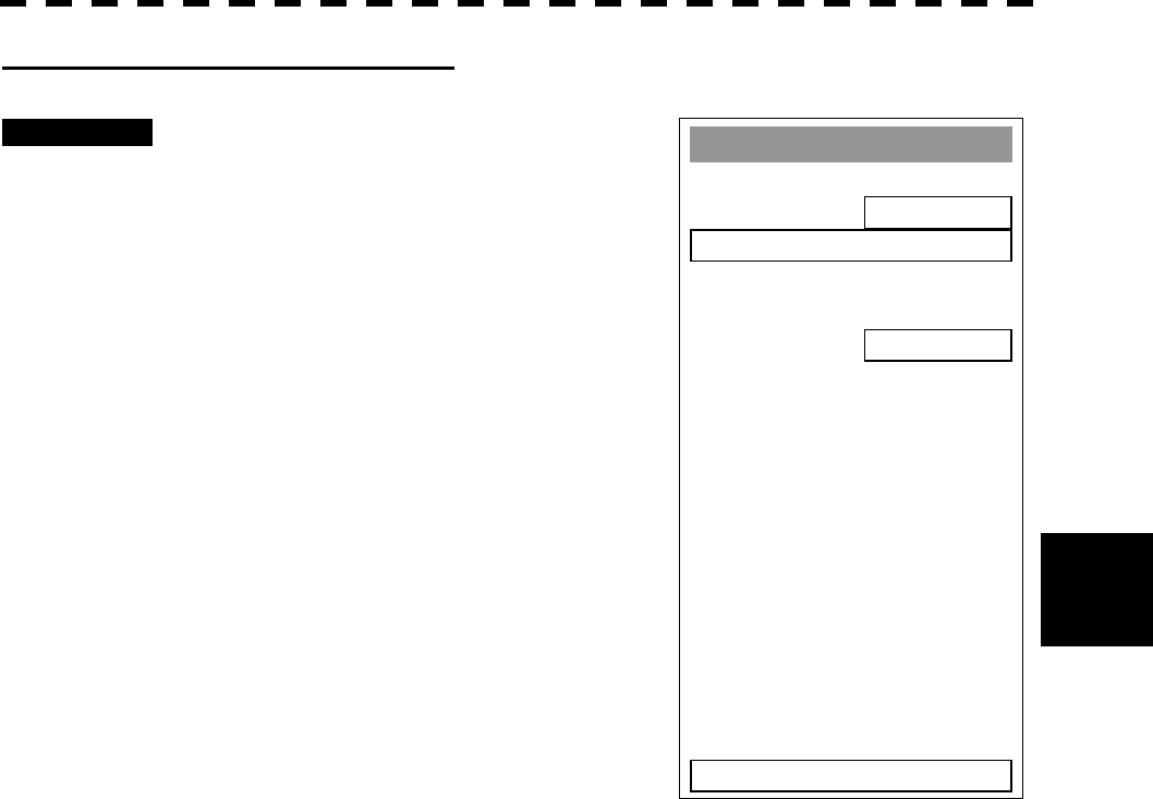
5─62
5.4
A
IS OPERATION
5
Making an AIS filter (Make AIS Filter)
Procedures 1 Press [2] key while the ATA Filter
Setting menu is open.
The Make AIS Filter screen will appear.
[I] Setting a RANGE filter
2 Turn the [VRM] key control to set a
filter range, and press [ENT] key.
The range of a RANGE filter will be set.
AIS targets in the set circle are displayed by
priority.
[II] Setting a SECTOR filter
2 Turn the [EBL] key control to set the
bearing of the port side, and press
[ENT] key.
3 Turn the [EBL] key control to set the
bearing of the starboard, and press
[ENT] key.
A SECTOR filter will be set.
AIS targets in the area formed by the two set bearings are displayed by priority.
[III] Setting a ZONE filter
2 Turn the [EBL] key and [VRM] key controls to set the bearing and range
of the port side, and press [ENT] key.
3 Turn the [EBL] key and [VRM] key controls to set the bearing and range
of the starboard, and press [ENT] key.
A ZONE filter will be set.
AIS targets in the area formed by the two set bearings and ranges are displayed by priority.
A
IS Filter Settin
g
1. Filter Type
RANGE
2. Make AIS Filter
3. Filter Display
ON
0. EXIT
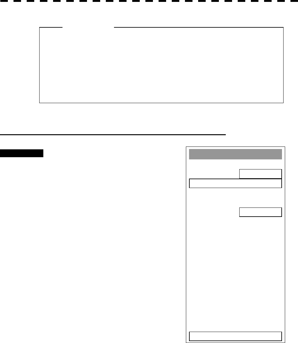
5─63
Setting the AIS filter display function to ON/OFF (Filter Display)
Procedures 1 Press [3] key while the ATA Filter
Setting menu is open.
The setting of AIS Filter display will be
switched ON or OFF.
ON: Displays the AIS filter.
OFF: Hides the AIS filter.
l When the guard zone function is enabled, the system
automatically corrects the filter range to cover the
guard zone. Thus, the guard zone is always inside
the filter range.
Attention
A
IS Filter Settin
g
1. Filter Type
RANGE
2. Make AIS Filter
3. Filter Display
ON
0. EXIT
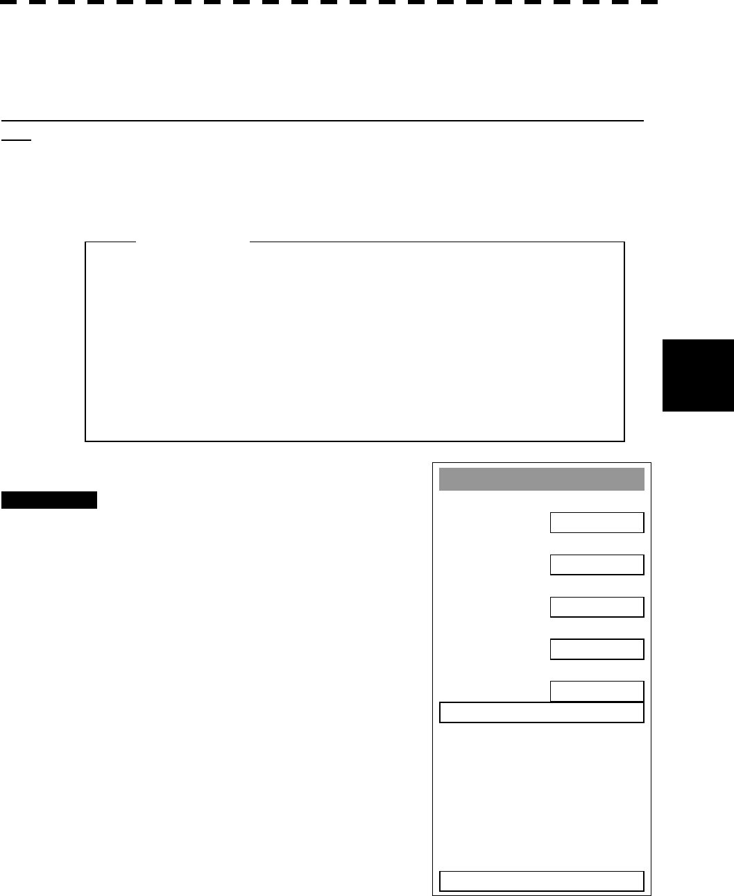
5─64
5.4
A
IS OPERATION
5
5.4.9 Deciding AIS Target and ARPA Target as the Same One
(Identical Distance)
Setting a range in which an AIS target and ARPA target are regarded as the same
one
An AIS target and an ARPA target in the set range are regarded as the same one, and the ARPA symbol is not
displayed. At this time, the AIS symbol is automatically activated.
Procedures 1 Press [ATA MENU] key.
Press [2] key.
The AIS Setting menu will appear.
2 Press [7] key.
The ten-key will appear.
3 Select the distance to be set pressing
the numeric key, and press [ENT] key.
The range in which an AIS target and ARPA
target are regarded as the same one will be set.
l To display the hidden ARPA symbol, set the AIS
symbol display function to OFF. (For the setting
procedure, refer to Section 5.4.5)
l Set 0 not to regard an AIS target and ARPA target as
the same one.
Attention
A
IS Settin
g
1. AIS Function
OFF
2. AIS Symbol Display
OFF
3. ATA Symbol Display
ON
4. CPA Limit
1 nm
5. TCPA Limit
1 min
6. AIS Filter Settin
g
>
7. Identical Distance
0. EXIT
5─65
CAUTION
When setting large values in determining the
distance to the same target, the ARPA target near
the AIS target may be not displayed.
For example, when a pilot ship with AIS function,
which is a small target, not ARPA target,
approaches to a cargo ship without ARPA
function, which is an ARPA target, the cargo ship’s
ARPA symbol may not be displayed.
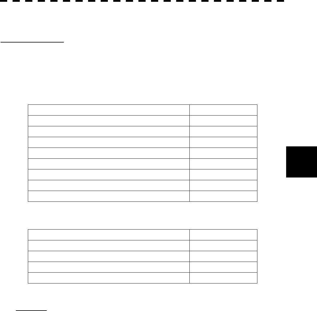
5─66
5.4
A
IS OPERATION
5
5.4.10 Conditions for Deciding AIS Target to be Lost
About a lost target
When the data of an AIS target cannot be received for a specified time, the target is decided to be lost and the
target data is deleted. As shown in the table below, the time until target data is deleted varies depending on the
class of receive data and the target status.
[SOLAS ship] (Class A)
Target Status Time until data deletion
Vessel below 3 knots and it is now at anchor or on the berth 18 min
Vessel of 3 knots or more and it is now at anchor or on the berth 60 sec
Vessel of 0 to 14 knots 60 sec
Vessel of 0 to 14 knots and it is now changing the course 60 sec
Vessel of 14 to 23 knots 36 sec
Vessel of 14 to 23 knots and it is now changing the course 36 sec
Vessel of 23 knots or more 12 sec
Vessel of 23 knots or more and it is now changing the course 12 sec
[Non-SOLAS ship] (Class B)
Target Status Time until data deletion
Vessel below 2 knots 18 min
Vessel of 2 to 14 knots 180 sec
Vessel of 14 to 23 knots 90 sec
Vessel of 23 knots or more 30 sec
Reference:
· When a dangerous target ship is lost, a lost alarm is issued and the symbol changes to a lost symbol. The
system calculates the current position from the last-received data and continues displaying the symbol for a
maximum of one minute. If the system cannot receive any data within one minute or the ALARM ACK
switch is pressed, the symbol is cleared.
· When a safe target ship is lost, the system does not issue a lost alarm, display a lost symbol, or calculate the
current position.

5─67
l If a vector is not displayed even when the AIS symbol
is activated, probable causes are as follows:
1. COG/SOG from the GPS has not been entered.
2. The selected speed sensor is malfunctioning.
5.4.11 Displaying AIS Symbols
Maximum number of targets and the display priority
A radar of the JMA-5300 series displays AIS symbols for a maximum of 50 targets. When 51 AIS targets or
more exist, they are displayed according to the following priority:
1. Target for which numeric data is displayed
2. Target displayed by the AIS target search function
3. arget in the AIS filter
(Targets closer to the own ship in the filter have higher priority.)
4. Target whose CPA/TCPA is the set value or less.
(Target for which a dangerous ship alarm has been issued)
5. Targets other than the above, which are outside the AIS filter
(Targets closer to the own ship in the filter have higher priority.)
Displaying the vectors of AIS symbols
The vector of an AIS symbol is to be displayed as a vector over water or over ground, depending on the speed
sensor setting and current offset setting. The type of the currently displayed vector is confirmed in the own
ship’s information display area at the upper right of the radar display.
When “GND” is displayed to the right of OS STAB: Vector over ground
When “SEA” is displayed to the right of OS STAB: Vector over water
When the vector of an AIS symbol is displayed as a vector over water, the system has converted the AIS
symbol’s vector over ground to the vector over water according to the data received from the AIS and the own
ship’s information.
l When the system receives the data of the 51-th target
ship, it displays AIS MAX TARGET at the right lower
of the radar display, and issues audible alarm (beep
sound of pipi).
Attention
Attention
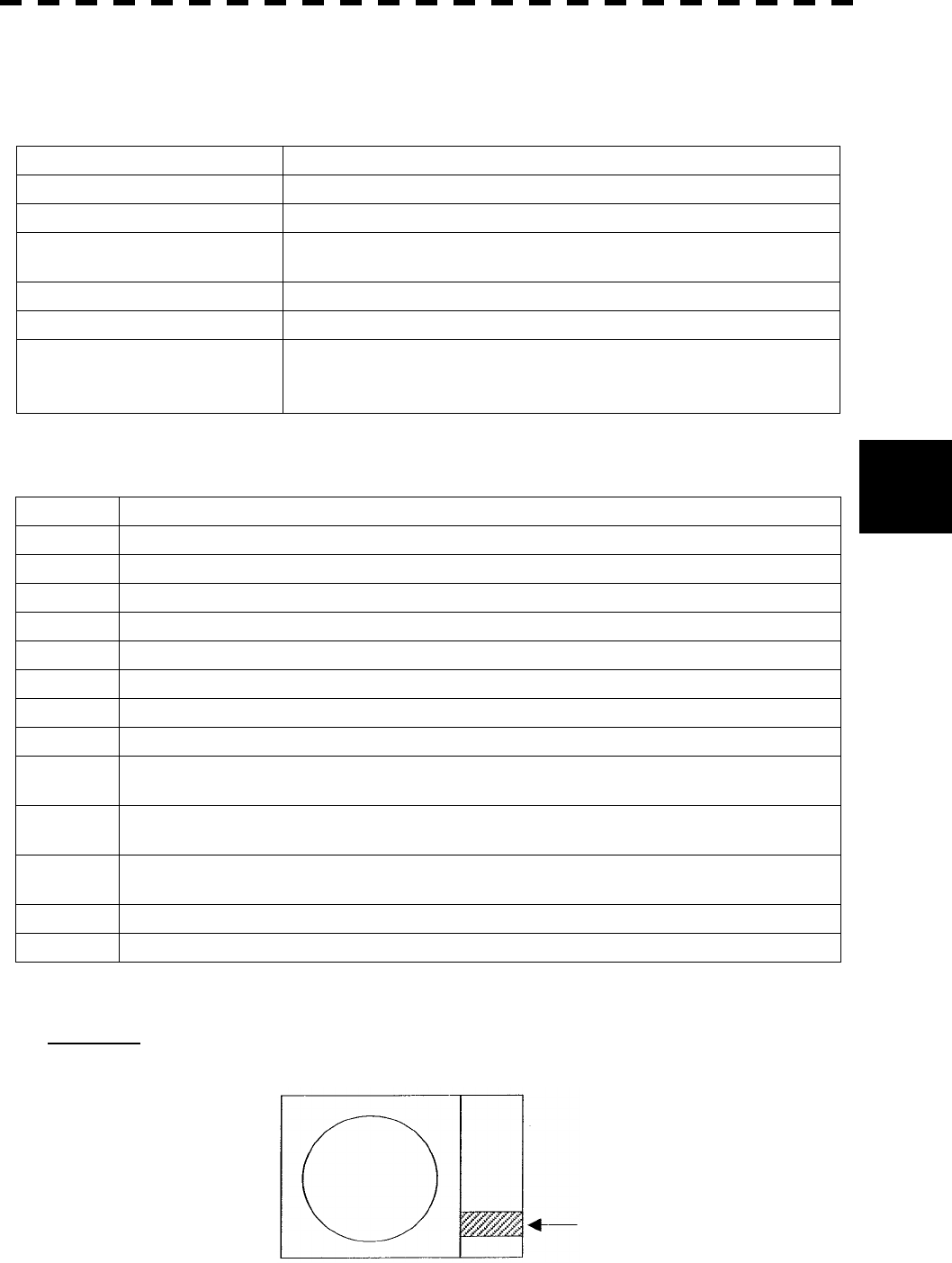
5─68
5.4
A
IS OPERATION
5
5.4.12 AIS Alarm Display
Alarm messages for the AIS system:
Error Message Description
COA/TCPA There is a dangerous target.
LOST There is a lost target.
AIS MAX TARGET The system received data (of the 51-th ship) over the specified maximum
number of AIS symbols.
AIS (DATA) The AIS is not connected correctly, or the power is off.
AIS I/F (DATA) The AIS interface is not connected to the radar correctly, or it is faulty.
AIS ALARM ***
Alarm information issued with the ALR sentence by the AIS
*** is a 3-digit number which is Local Alarm No in the ALR sentence.
For AIS alarms, refer to the table below.
Numbers and definitions of AIS alarms which might appear on the radar display
Alarm No. Definition
001 Transmission alarm
002 VSWR calculation result alarm
003 Receive channel 1 alarm
004 Receive channel 2 alarm
005 Receive channel 70 alarm
006 General error
008 Connection alarm between the transponder and controller
025 External EPFS connection alarm
026 The internal GPS is disabled, and latitude/longitude data has not been received from the external
sensor or the data is invalid.
029 The internal GPS is disabled, and SOG data has not been received from the external sensor or the
data is invalid
030 The internal GPS is disabled, and the COG command below has not been received from the
external sensor or the data is invalid.
032 Course data has not been received from the external sensor, or the data is invalid.
035 ROT data has not been received from the external sensor, or the data is invalid.
Reference: An error message is displayed at the lower right of the radar display.
Error message display area

5─69
5.4.13 Restrictions
The following restrictions are placed on use of the AIS function:
The AIS function is unavailable in the following cases:
· “MANUAL” is selected for the speed sensor.
· SET or DRIFT is set while LOG or 2AXW is selected for the speed sensor.
LOG or 2AXW cannot be selected for the speed sensor in the following case:
· SET or DRIFT is set while the AIS function is on.
MANUAL cannot be selected for the speed sensor in the following case:
· The AIS function is on.
Current offset (SET/DRIFT) cannot be turned on in the following case:
· LOG or 2AXW is selected for the speed sensor while the AIS function is on.

SECTION 6
TRUE AND FALSE ECHOES
ON DISPLAY
6.1 Radar Wave with the Horizon....................6-2
6.2 Strength of Reflection from the Targets ..6-4
6.3 Sea Clutters ................................................6-5
6.4 False Echoes ..............................................6-6
6.5 Display of Radar Transponder (SART).....6-9

6─1
The radar operator has a role of interpreting the radar displays to provide his best aid in maneuvering the ship.
For this purpose, the operator has to observe the radar displays after fully understanding the advantages and
disadvantages that the radar has. For better interpretation of radar display, it is important to gain more
experiences by operating the radar equipment in fair weathers and comparing the target ships watched with the
naked eyes and their echoes on the radar display.
The radar is mainly used to monitor the courses of own ship and other ships in open seas, to check buoys and
other nautical marks when entering a port, to measure own ship’s position in the coastal waters relative to the
bearings and ranges of the shore or islands using a chart, and to monitor the position and movement of a heavy
rain if it appears on the radar display.
Various types of radar display will be explained below.
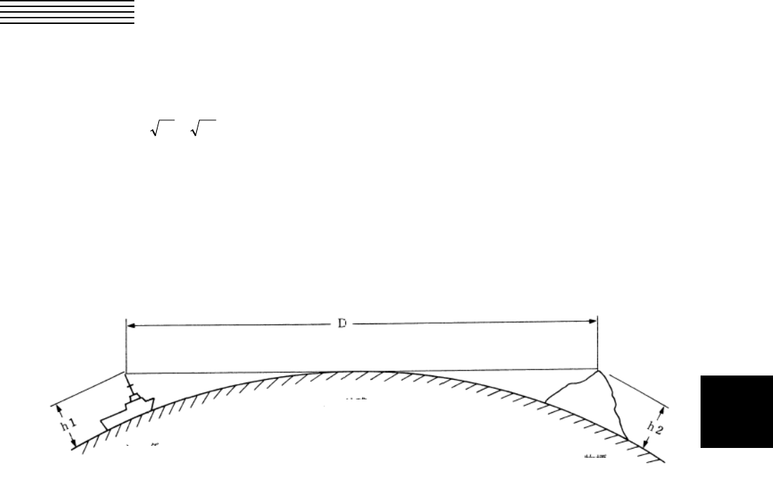
6─2
6
6.1 RADAR WAVE WITH THE HORIZON
Radar beam radiation has the nature of propagating nearly along the curved surface of the earth.
The propagation varies with the property of the air layer through which the radar beam propagates.
In the normal propagation, the distance (D) of the radar wave to the horizon is approximately 10% longer than
the distance to the optical horizon. The distance (D) is given by the following formula:
D=2.23( h2h1 +)(nm)
h1: Height (m) of radar scanner above sea level
h2: Height (m) of a target above sea level
Figure 6.1 is a diagram for determining the maximum detection range of a target that is limited by the curve of
the earth surface in the normal propagation.
Radar
Earth
Targets
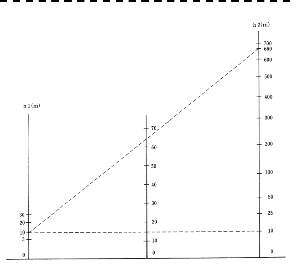
6─3
Figure 6.1
When the height of own ship’s scanner is 10 m for instance,
(a) A target that can be detected at the radar range of 64 nm on the radar display is required to have a height
of 660 m or more.
(b) If the height of a target is 10 m, the radar range has to be approx. 15 nm. However, the maximum
radar range at which a target can be detected on the radar display depends upon the size of the target
and the weather conditions, that is, the radar range may increase or decrease depending upon those
conditions.
Height of Radar Scanner Detective Range Height of Target
D (nm)
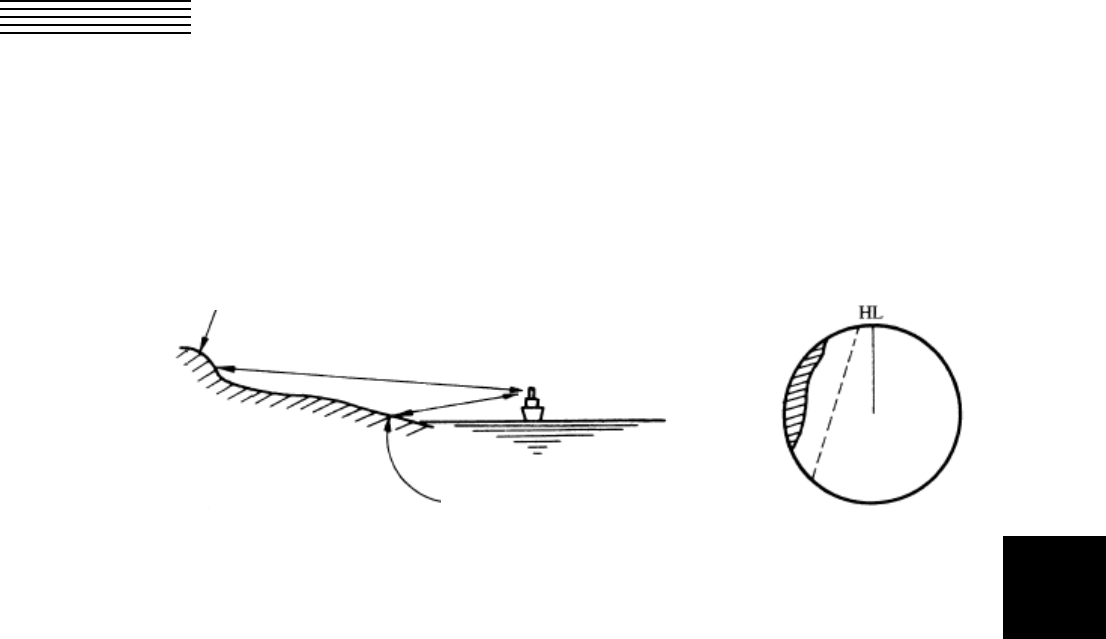
6─4
6
6.2 STRENGTH OF REFLECTION FROM THE
TARGET
The signal intensity reflected from a target depends not only on the height and size of the target but also on its
material and shape. The echo intensity from a higher and larger target is not always higher in general.
In particular, the echo from a coast line is affected by the geographic conditions of the coast.
If the coast has a very gentle slop, the echo from a mountain of the inland appears on the radar display.
Therefore, the distance to the coast line should be measured carefully.
Figure 6.2
Mountain displayed on the radar display
Sea shore line not displayed
on the radar display.

6─5
6.3 SEA CLUTTERS
When the sea surface ruffles, bright echo returns spread around the center of the radar display.
The higher the waves are, the echo returns are larger.
Swirling currents may appear as a smooth line like a coastal line.
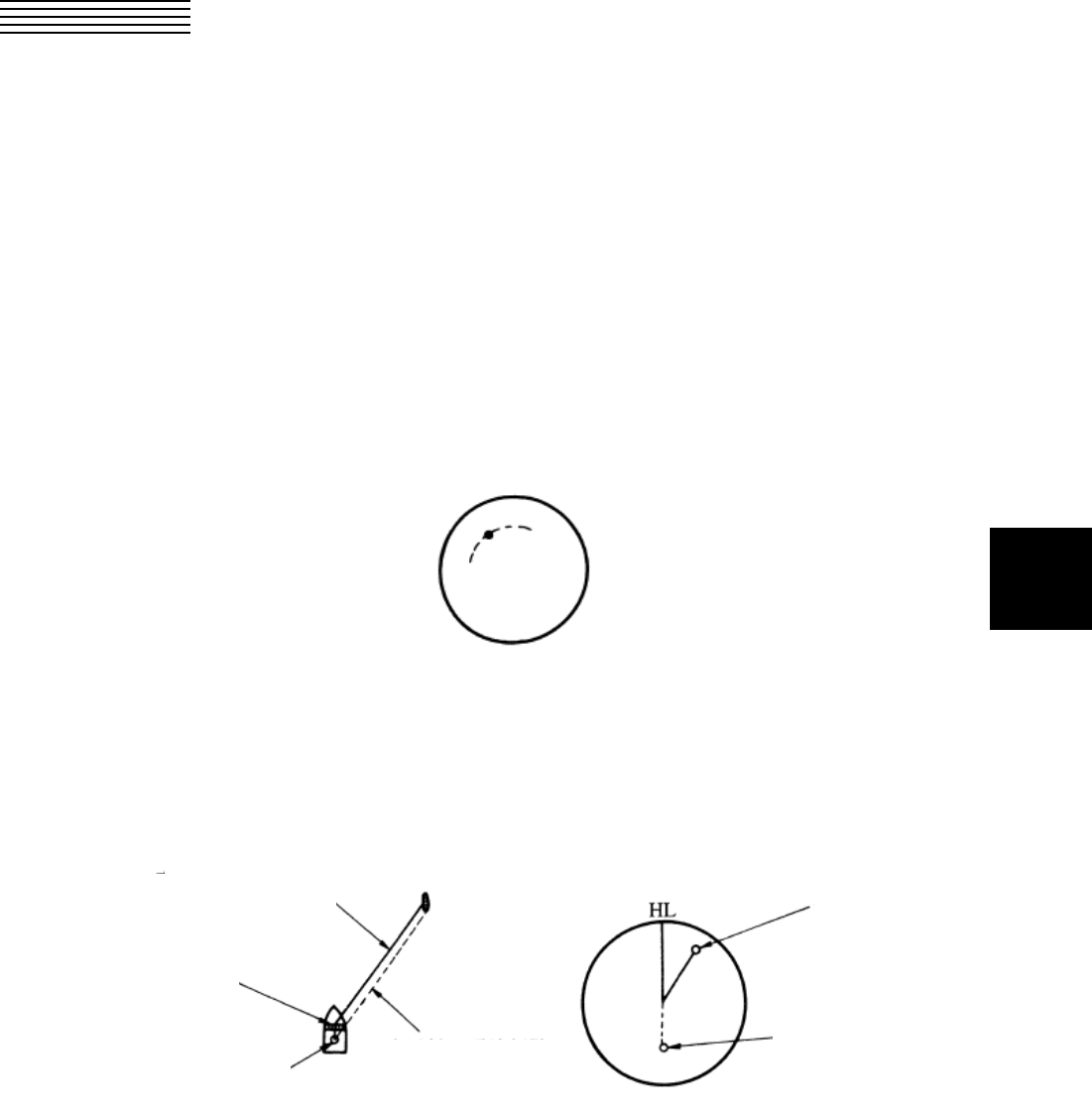
6─6
6
6.4 FALSE ECHOES
The radar observer may be embarrassed with some echoes that do not exist actually. These false echoes
appear by the following causes that are well known:
[I] Shadow
When the radar scanner is installed near a funnel or mast, the echo of a target that exists in the direction of
the funnel or mast cannot appear on the radar display because the radar beam is reflected on the funnel or
mast. Whether there are some false echoes due to shadows can be checked monitoring the sea clutter
returns, in which there may be a part of weak or no returns.
Such shadows appear always in the same directions, which the operator should have in mind in radar
operation.
[II] Side Lobe Effect
A broken-line circular arc may appear at the same range as the main lobe of the radar beam on the radar
display. This type of false echo can easily be discriminated when a target echo appears isolated. (See
Figure 6.3)
Figure 6.3
[III] False Echo by Secondary Reflection
When a target exists near own ship, two echoes from the single target may appear on the radar display.
One of those echoes is the direct echo return from the target and the other is the secondary reflection return
from a mast or funnel that stands in the same direction as shown in Figure 6.4.
Figure 6.4
Direct microwave
Radar scanner
Funnel
Actual target
Secondary reflection
of microwave
False echo from funnel
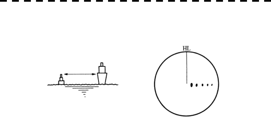
6─7
[IV] False Echo by Multiple Reflection
When there is a large structure or ship with a high vertical surface near own ship as shown in Figure 6.5,
multiple refection returns may appear on the radar display. These echoes appear in the same intervals, of
which the nearest echo is the true echo of the target.
Figure 6.5
[V] Abnormal Propagation
The maximum radar detection range depends upon the height of the scanner and the height of a target as
described in the section of “The Horizon for Radar Beam Radiation”. If a so-called “duct” occurs on the
sea surface due to a certain weather condition, however, the radar beam may propagate to a abnormally
long distance, at which a target may be detected by the radar.
For instance, assuming that the radar range is 6 NM (on the repetition frequency of 1100 Hz), the first
pulse is reflected from a target at about 76 NM or more and received during the next pulse repetition time.
In this case, a false echo appears at a position that is about 76 NM shorter than the actual distance.
If the false echo appears at 5 NM on the radar display, the true distance of the target is 5+76=81 NM. On
the radar range scale of 1.5 NM (on the repetition frequency of 1900 Hz), a false echo may appear at a
position that is about 43 NM shorter than the actual distance.
This type of false echo can be discriminated by changing over the range scale (the repetition frequency),
because the distance of the target changes accordingly.
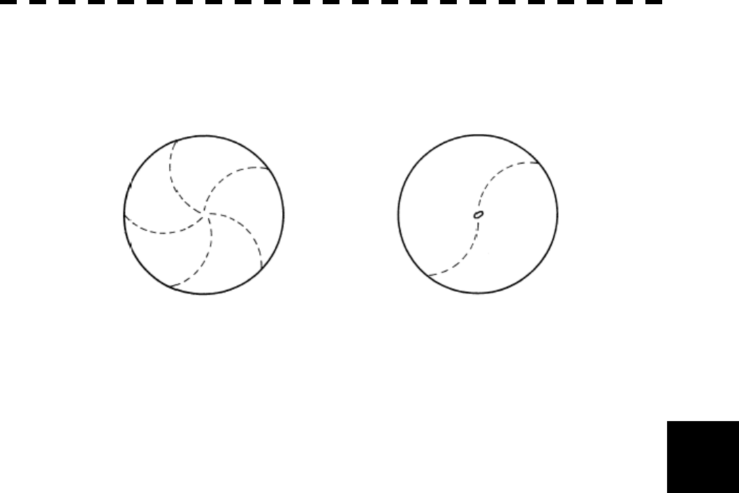
6─8
6.4 FALSE ECHOES
6
[VI] Radar Interference
When another radar equipment using the same frequency band as that on own ship is near own ship, a
radar interference pattern may appear on the radar display. This interference pattern consists of a number
of spots which appear in various forms. In many cases, these spots do not always appear at the same
places, so that they can be discriminated from the target echoes. (See Figure 6.6)
Figure 6.6
If radar equipment causing an interference pattern and this radar are of the same model, their transmitting
repetition frequency is nearly the same. As a result, interference patterns may be displayed
concentrically.
In this case, the interference patterns cannot be eliminated by using only the interference reflector function,
so press [TX/PRF] several times to fine-tune the transmitting repetition frequency.
An interference suppressing effect can be heightened by applying a different transmitting repetition
frequency to the interference pattern source radar and this radar.
6─9
6.5 DISPLAY OF RADAR TRANSPONDER
(SART)
The SART (Search and rescue Radar Transponder) is a survival device authorized by the GMDSS (Global
Maritime Distress and Safety System), which is used for locating survivors in case that a distress accident
occurs at sea. The SART is designed to operate in the 9 GHz frequency band.
When receiving the 9 GHz radar signal (interrogating signal) transmitted from the radar equipment on a rescue
ship or search aircraft, the SART transmit a series of response signals to inform the distress position to the
rescue and search party.
* This radar provides a shortcut item to make settings for SART signal reception. Execution of this item
automatically switches to the setting for SART reception.
Procedures 1 Press [RANGE +] or [RANGE -] to
set the radar range to 6 NM or 12
NM.
2 Press [RADAR MENU].
The Main Menu will appear.
3 Press [5].
Each time the key is pressed, switching between
ON and OFF takes place.
MAIN MENU
1. I
R
IR OFF
2. Process
PROC OFF
3. Tar
g
et Enhance
OFF
4. Zoom
OFF
5. SART
ON
6. NA
V
Information >
8. Graphic Display
ON
9. RADAR MENU(→Plot)
0. EXIT

6─10
6.4 FALSE ECHOES
6
With the SART display mode set to ON, settings as shown below are made automatically.
(1) Sea clutter control: Minimum (Most counterclockwise)
(2) AUTO SEA function: OFF
(3) Rain and Snow Clutter Control (RAIN): minimum
(4) Auto Rain and Snow Clutter function (AUTO RAIN): OFF
(5) TUNE control: No tuning (to weaken clutter echoes)
(6) Interference rejector (IR): OFF
(7) PROCESS: OFF
[Example of Display]
SART code
Position of SART
Position of the rescue craft
Other ships
Land
l When the SART function is set to ON to detect the SART signal, small
targets around own ship will disappear from the radar display. So it is
necessary to exercise full surveillance over the conditions around own
ship by visual watch in order to avoid any collision or stranding.
If two or more sets of radar equipment are installed on own ship, use
one set of 9 GHz band radar for detection of the SART signal and
operate others as normal radars for avoiding collision, monitoring
targets around own ship, and checking on own ship’s position and
avoidance of stranding.
After end of detecting the START signal, turn the START display off.
Then the radar returns normally to the nautical mode.
Attention
SECTION 7
MAINTEMANCE
7.1 Routine Maintenance .................................... 7-1
7.2 Maintenance on Each Unit ........................... 7-2
Scanner Unit NKE-2102/2252/1075A............ 7-2
Display Unit NCD-4510 ................................. 7-8
7─1
7.1 ROUTINE MAINTENANCE
WARNING
Never carry out internal inspection or repair work
of the equipment by users.
Inspection or repair work by unauthorized
personnel may result in fire hazard or electric
shock.
Ask the nearest branch, business office or a dealer
for inspection and repair.
Turn off the main power before maintenance work.
Otherwise, an electric shock may result.
Turn off the main power before cleaning the
equipment. Especially, make sure to turn off the
indicator if a rectifier is used. Otherwise,
equipment failure, or death or serious injury due to
electric shock may result, because voltage is
outputted from the rectifier even when the radar is
not operating.
For operating the radar equipment in the good conditions, it is necessary to make the maintenance work as
described below. If maintenance is made properly, troubles will reduce. It is recommended to make regular
maintenance work.
Common points of maintenance for each unit are as follow:
Clean the equipment.
Remove the dust, dirt, and sea water rest on the equipment cabinet with a piece of dry cloth.
Especially, clean the air vents with a brush for good ventilation.
7─2
7
7.2 MAINTENANCE ON EACH UNIT
Scanner Unit NKE-2102/2252/1075A
WARNING
Turn off the main power source before starting
maintenance.
Otherwise, an electric shock or injury may be
caused.
Turn off the main power if you need to be near the
scanner unit for maintenance or inspection
purposes. Direct exposure to electromagnetic
waves at close range in death or serious injury.
Set the safety switch for stopping the scanner unit
to the OFF position.
Otherwise, an accidental contact with the rotating
scanner unit may cause injury.

7─3
CAUTION
Do not put watches, clocks, or magnetic cards
close to the modulator unit since this unit holds
magnetrons having strong magnetic force.
Failure or data destruction of the above devices
may result.
After finishing the maintenance work, reset the safety switch to the ON position.
Precautions in Mounting the Cover
When the cover is removed for regular checkup and replacement of parts and refitted after such work, the
procedures of fastening bolts shall be taken with the following precautions:
(a) The proper fastening torque of the fitting bolts (M8) is 1176 to 1470 N•cm (120 to 150kgf•cm) (which
makes the inside water-tight and protects the packings against permanent compressive strain).
The packings start producing from the cover at a torque of approximately 1470N•cm (150kgf•cm).
Do not fasten the bolts with a torque exceeding the specified value. Otherwise, the screws may be
broken.
(b) Use an offset wrench of 11 mm ´ 13 mm or a double-ended wrench of 13 mm ´ 17 mm (not longer than
200 mm).
(c) Screw all the bolts by hand first to prevent them playing, then fasten them evenly in order not to cause
one-sided fastening. (Fasten the bolts with 25% of the required torque at the first step.)
*: Fasten the bolts in the diagonal order.
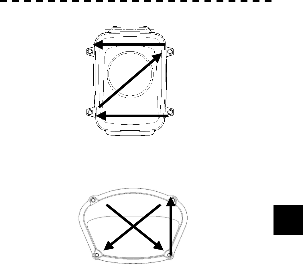
7─4
7.2 Maintenance on each Uni
t
7
Top View of NKE-2102
Bolt Tightening Procedure of NKE-2102 Cover
Side View of NKE-2252
Bolt Tightening Procedure of NKE-2252 Cover
④ ③
② ①
① ③
④ ②
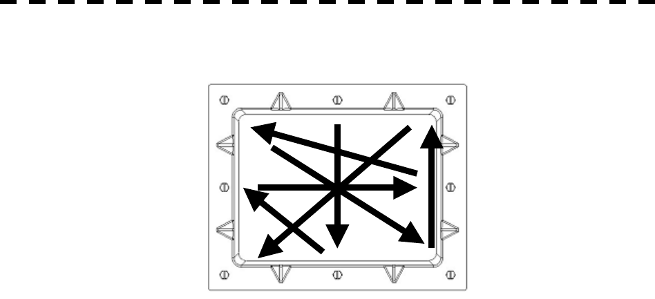
7─5
Side View of NKE-1075A
Bolt Tightening Procedure of NKE-1075A Cover
①
③ ④
②
⑤
⑥
⑦
⑧

7─6
7.2 Maintenance on each Uni
t
7
(1) Radiator
Check up and clean the radiator.
l If the radiator front face (radiation plane) is soiled
with smoke, salt, dust, paint or birds’ droppings,
wipe it with a piece of soft cloth wetted with alcohol
or water and try to keep it clean at all times.
Otherwise, radar beam radiation may attenuate or
reflect on it, resulting in deterioration of radar
performance.
l Never use solvents of gasoline, benzine,
trichloroethylene and ketone for cleaning.
Otherwise, the radiation plane may deteriorate.
Attention

7─7
(2) Rotating section
(a) Supply Oil Seal
When there is not a grease nipple, the replenishment of grease oil is unnecessary.
Remove the cap on the grease nipple located on the side of the X band radar or on the front of S
band radar at which the radiator is supported, and grease with a grease gun.
Make the oiling every six months. The oil quantity shall be approximately 100 g, which is as much
as the grease comes out of the oil seal. Use the grease of Mobilux 2 of Mobil Oil.
(b) Oiling gears
Apply grease evenly to the tooth surfaces of the main shaft drive gear and the encoder drive gear
with a spreader or brush. Oiling in short intervals is more effective to prevent the gears from wear
and tear and extend their service life, but oil at least every six months.
Use Mobilux2 of Mobile Oil.
(c) Mounting legs
Check the mounting legs and mounting bolts of the scanner unit case for corrosion at intervals and
maintain them to prevent danger. Apply paint to them once a half year because painting is the best
measure against corrosion.

7─8
7.2 Maintenance on each Uni
t
7
Display Unit NCD-4510 ・・・・・・・・・・・・・・・・・・・・・・・・・・・・・・・・・・・・・・・・・・・・・・・・・・・・・
WARNING
When cleaning the screen, do not wipe it too
strongly with a dry cloth. Also, do not use
gasoline or thinner to clean the screen. Otherwise
the screen surface may be damaged.
Dust accumulated on the screen will reduce clarity and darken the video. For cleaning it, wipe it with a piece
of soft cloth (flannel or cotton). Do not wipe it strongly with a piece of dry cloth nor use gasoline or thinner.

SECTION 8
TROUBLE SHOOTING
AND ADJUSTMENT
8.1 Performance Check..........................8-1
8.2 Fault Finding...................................8-21
8.3 Trouble Shooting ............................ 8-22
8.4 Replacement of Major Parts .......... 8-27
8.5 Adjustments....................................8-30
8.6 Setting ............................................. 8-62
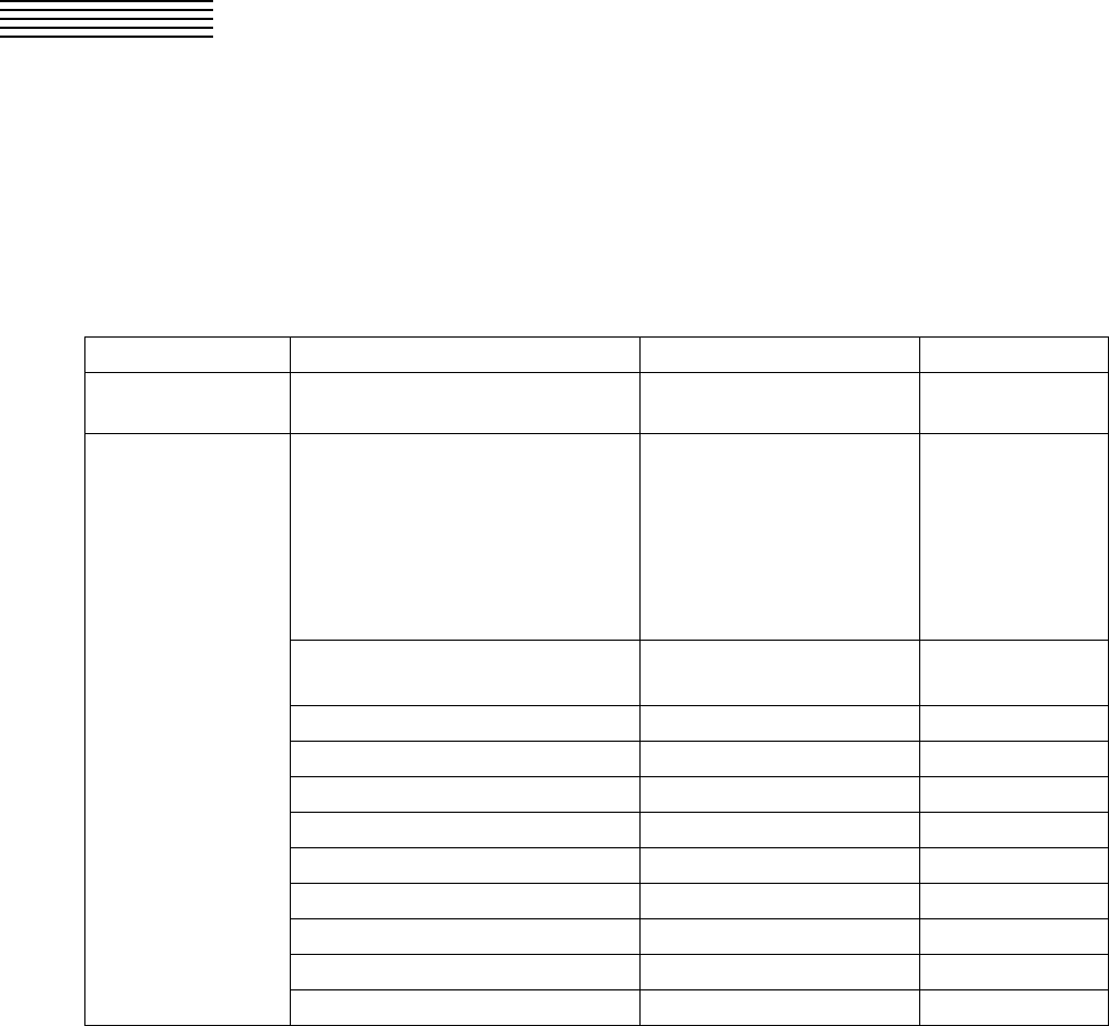
8─1
8.1 PERFORMANCE CHECK
Make operational check on the radar equipment regularly and if any problem is found, investigate it
immediately. Pay special attention to the high voltage sections in checking and take full care that no trouble is
caused by any error or carelessness in measurement. Take note of the results of checking, which can be used
effectively in the next check work.
Operational check shall be made in accordance with Table 8-1 Function Check List in the order as specified in
it.
Table 8-1 Check List
Equipment Item to be checked Criteria Remarks
Transmitter-receiver
Unit Tuning LED of Receiver The LED is lighting during
operation 48NM range
Video and echoes on the screen
Sensitivity
LCD brilliance can be controlled
correctly
Various markers
Various numerical indications
Lighting
Can be correctly controlled
Safety Switch
Various Currents and Voltages See 8-5.
Communications Lines See 8-6.
Memory See 8-4.
Panel See 8-8, -9, -10, -11.
Monitor See 8-7.
ARPA See 8-42.
Magnetron current See 8-18.
Performance Monitor See 8-12.
Error Logging Display See 8-13.
Display Unit
System Information Display See 8-17.
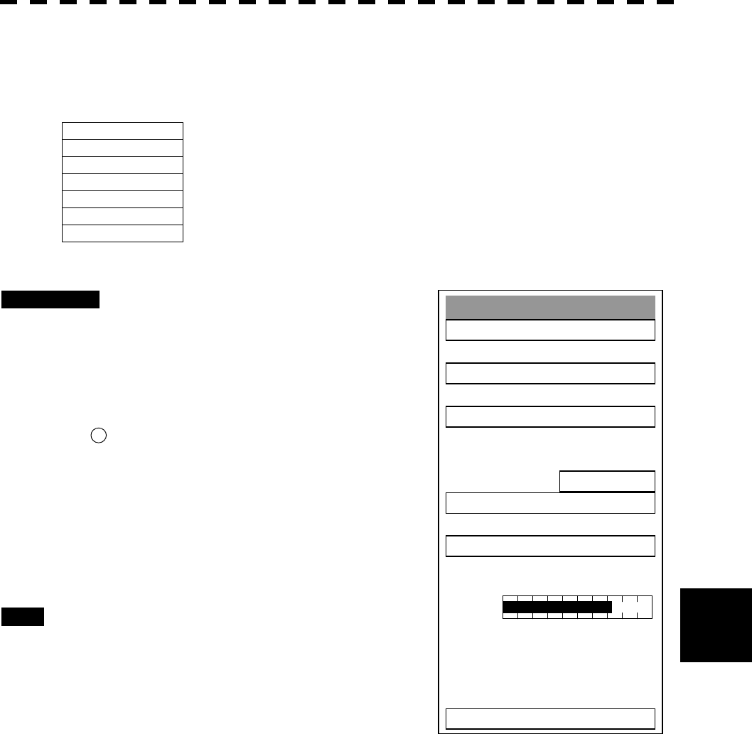
8─2
8
8.1 Performance Check
Test Menu
1. Self Test
2. Monitor Test
3. Keyboard Test
4. PM Display
ON
5. Error Lo
gg
in
g
6. System INFO
0. EXIT
MAGI
Check Performance on Test Menu
The performance status of this radar equipment can be checked on the TEST Menu.
Self Test [I] Self-diagnostic function
Monitor Test [II] Monitor check
Keyboard Test [III] Operation panel check
PM Display [IV] Performance monitor
Error Logging [V] Error log display
System INFO [VI] System information display
MAGI
[VII] Indication of magnetron current
* Execution of PM Display requires a PM unit.
Procedures 1 Press [RADAR MENU] key twice.
Press [8] key.
Press [9] key.
The TEST Menu will appear.
* Button 57 on the radar display on page 2-7 is also available.
2 Select the check item you want to
check, pressing the numeric keys [1]
to [6] on Test Menu.
The list of check items will appear.
Exit 1 Press [RADAR MENU] key.
The TEST Menu will be closed.
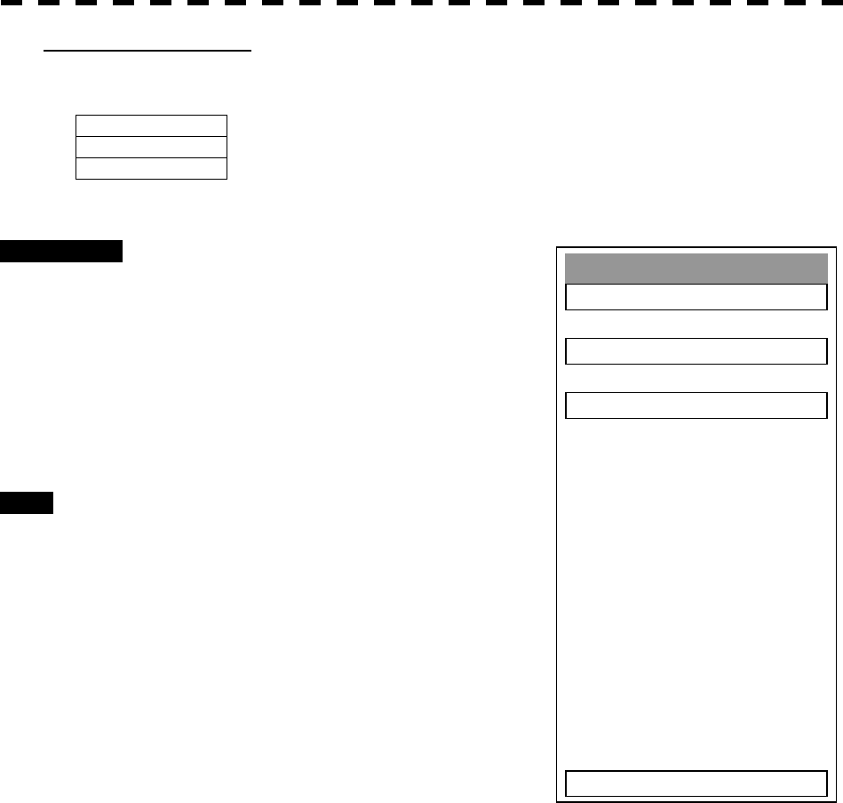
8─3
Self Test
1. Memory Test
2. Sensor Test
3. Line Test
0. EXIT
[I] Self-diagnosis function
Check of Memory, Scanner Unit, and Communications Lines
Memory Test 1) Memory check
Sensor Test 2) Antenna check
Line Test
3) Communication line check
Procedures 1 Press [1] key while the Test Menu is
open.
The SELF TEST Menu will appear.
2 Select the item you want to check,
pressing numeric keys [1] to [3] .
The SELF CHECK Menu will appear.
Exit 1 Press [RADAR MENU] key.
The Self Test Menu will be closed.
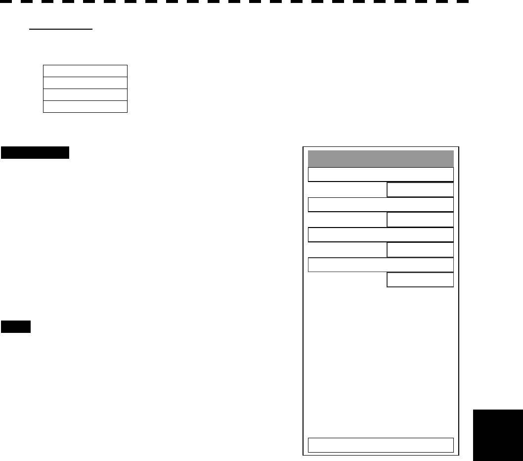
8─4
8
8.1 Performance Check
Memory Test
1. SDRAM
O
K
2. SRAM
O
K
3. FLASH ROM
O
K
4. GRAPHIC
O
K
0. EXIT
1) Memory Test
Checks for the performance of built-in memory.
SDRAM SDRAM check
SRAM SRAM check
FLASH ROM Flash ROM check
GRAPHIC
Graphic check
Procedures 1 Press [1] key while the Self Test
menu is open.
The Memory Test Menu will appear.
2 Select the item you want to check,
pressing numeric keys [1] to [4].
When no abnormality is found, OK is
displayed.
When an abnormality is found, NG is
displayed.
Exit 1 Press [RADAR MENU] key.
The menu will be closed.
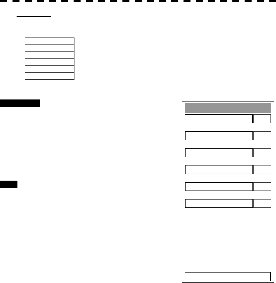
8─5
Sensor Test
O
K
※ Safety Switch
0. EXIT
O
K
※ AZI Pulse
O
K
※ HL Pulse
O
K
※ MH Current
O
K
※ Tri
gg
er
O
K
※ Video
2) Sensor Test
Checks for signals from the antenna.
Safety Switch Antenna’s safety switch check
AZI Pulse Antenna rotation signal check
HL Pulse Heading line signal check
MH Current Check on the load current of high voltage in the modulator
Trigger Radar trigger signal check
Video
Radar video check
Procedures 1 Press [2] key while the Self Test menu
is open.
The Sensor Test menu will appear.
When no abnormality is found, OK is
displayed.
When an abnormality is found, NG is
displayed.
In standby, ** will appear.
Exit 1 Press [RADAR MENU] key.
The menu will be closed.
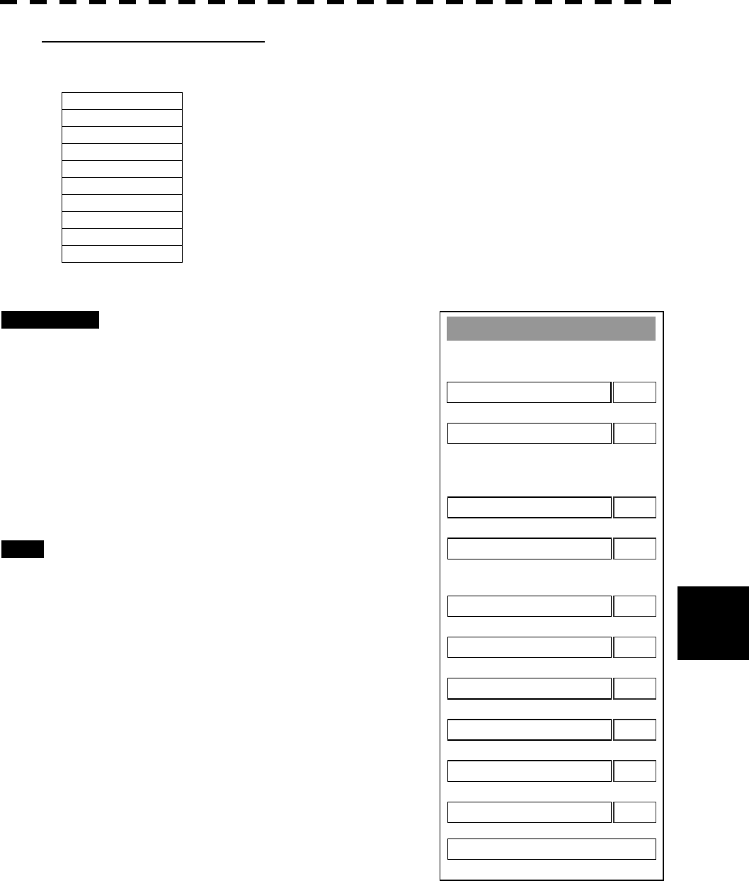
8─6
8
8.1 Performance Check
3) Check of Communication Lines
Check the status of communications with options.
MTR Check on connection with the transmitter-receiver
SIG.PROC Check on connection with the signal processing circuit
ATA Check on connection with the ARPA processing circuit
NSK Check on connection with the NSK unit
GPS Compass Check on connection with the GPS compass
ISW Check on connection with the interswitch
COM1 Check on connection with COM1
COM2 Check on connection with COM2
COM3 Check on connection with COM3
COM4
Check on connection with COM4
Procedures 1 Press [3] key with the Self Test menu
open.
The Line Test menu will appear.
When no abnormality is found, OK is
displayed.
When an abnormality is found, NG is
displayed.
The status display field of equipment not
connected is left blank.
Exit 1 Press [RADAR MENU] key.
The menu will be closed.
Line Test
O
K
※ MT
R
0. EXIT
O
K
※ SIG.PROC
O
K
※ AT
A
O
K
※ NS
K
O
K
※ GPS Compass
O
K
※ ISW
O
K
※ COM1
O
K
※ COM2
O
K
※ COM3
O
K
※ COM4
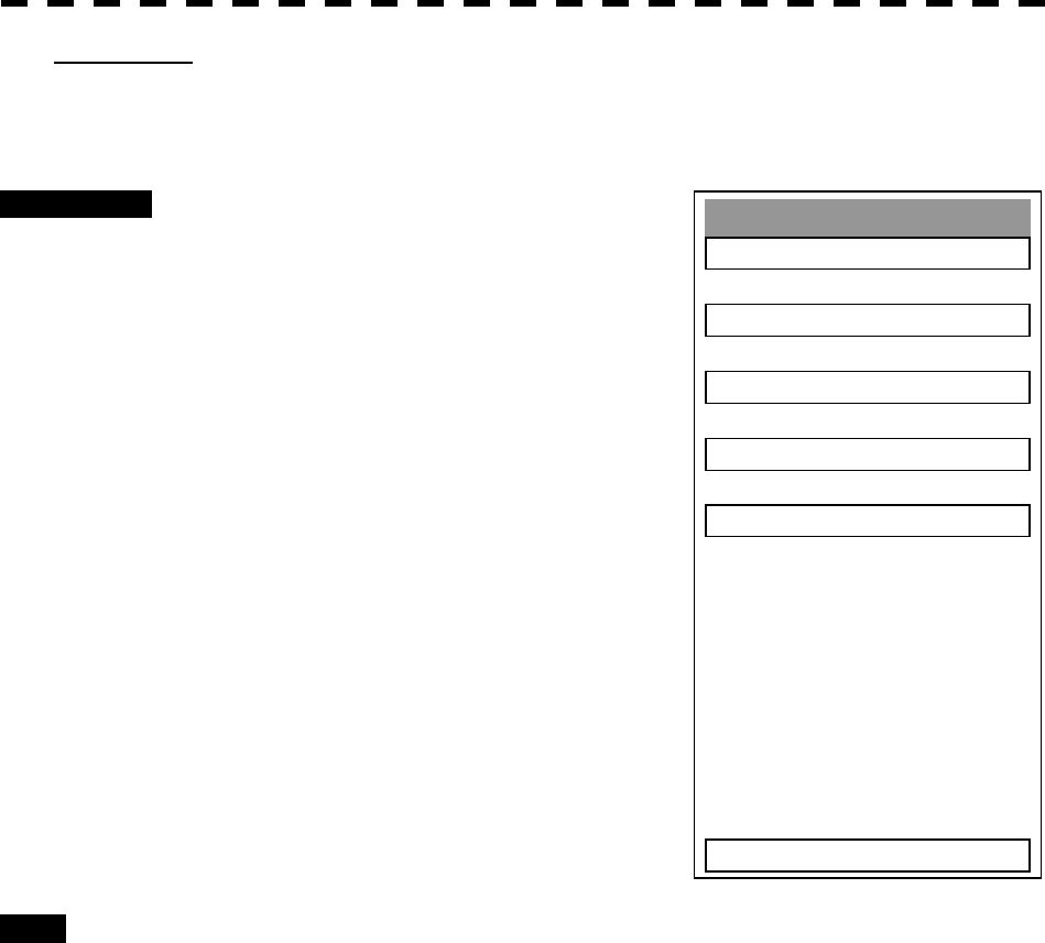
8─7
Monitor Test
1. Pattern 1
2. Pattern 2
3. Pattern 3
4. Pattern 4
5. Pattern 5
0. EXIT
[II] Monitor Test
Checks for the monitor.
Procedures 1 Press [2] key while the Test Menu is
open.
The Monitor Test Menu will appear.
2 Select the item number you want to
display, pressing numeric keys [1] to
[5] of the test pattern.
The selected test pattern will be displayed.
Pattern 1: All colors are filled with white.
Pattern 2: A white box is displayed on the black background of
1280 ´ 1024 dots.
Pattern 3: Displays rectangle ´ 2, circle ´ 2, and cross-shape´
13 (white lines on the black background).
Pattern 4: Displays “H” of 9 dots ´ 9 dots on the entire screen
(white character on the black background).
Pattern 5: Gray scale display (16 levels)
Pattern 6: Displays a color bar.
3 To return to the original display, press
any key.
If errors occur in the monitor, no test pattern
will appear.
Exit 1 Press [RADAR MENU] key.
The menu will be closed.
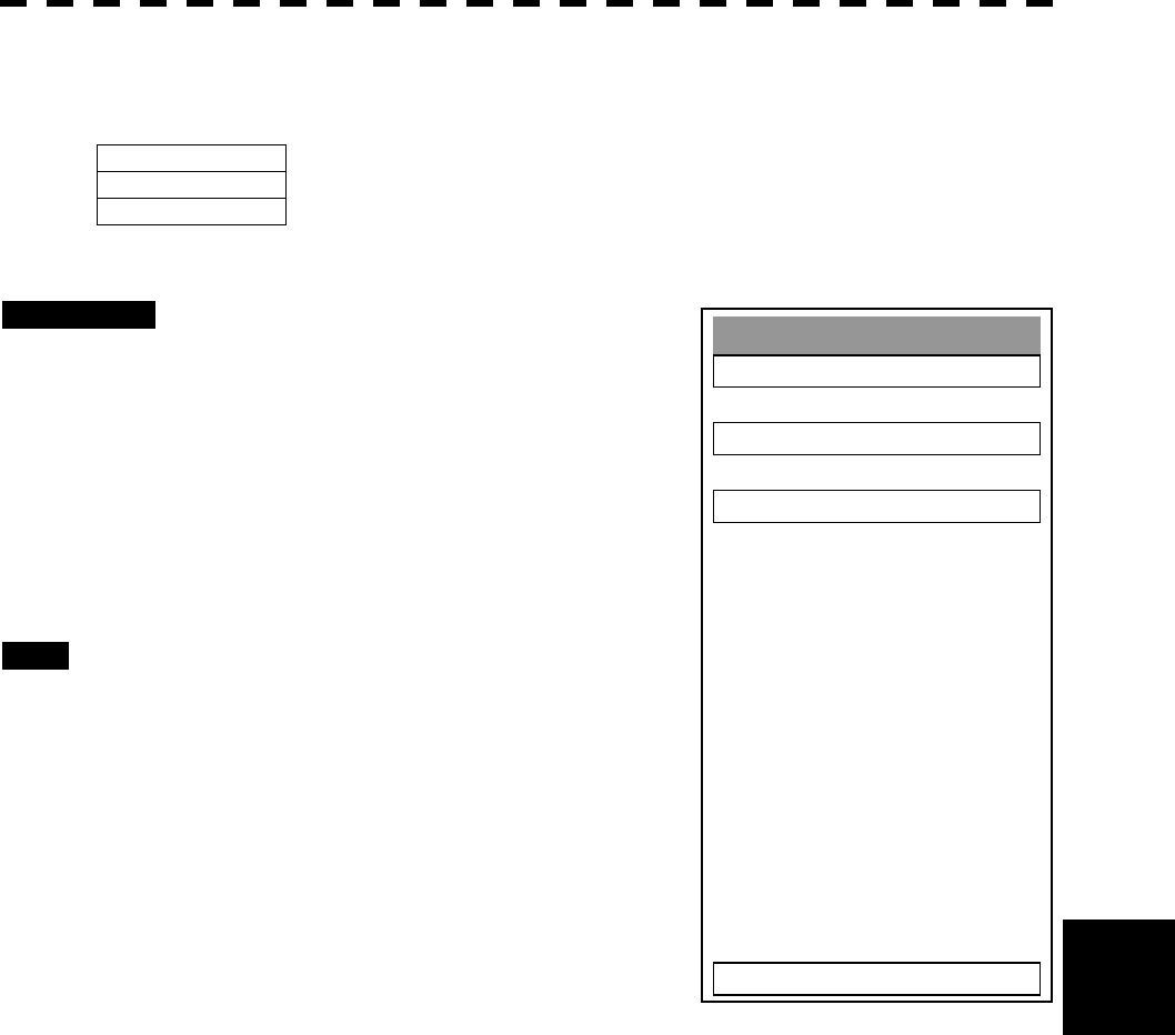
8─8
8
8.1 Performance Check
Keyboard Test
1. Key Test
2. Buzzer Test
3. Li
g
ht
0. EXIT
[III] Operation Panel Test
Checks for the controls and switches of the operation panel.
Key Test 1) Key check
Buzzer Test 2) Buzzer check
Light
3) Keyboard light check
Procedures 1 Press [3] key while the Test Menu is
open.
The Keyboard Test Menu will appear.
2 Select the item number you want to
check, pressing numeric keys [1] to [3]
of the item.
The check contents will be displayed.
Exit 1 Press [RADAR MENU] key.
The menu will be closed.

8─9
1) Key Check
Checks for the controls and switches of the operation panel.
Procedures 1 Press [1] key while the Keyboard Test
menu is open.
The operation panel image will appear at the
upper left of the display.
Each key on the operation panel on the display is
shown in reverse video at the same time the key
is pressed, and the name of the pressed key is
displayed.
2 To return to the normal display, move
the cursor onto “EXIT” on the left side
of the display, and press [ENT] key.
Exit 1 Press [0] key.
The menu will be closed.
Keyboard Test
1. Key Test
2. Buzzer Test
3. Li
g
ht
0. EXIT
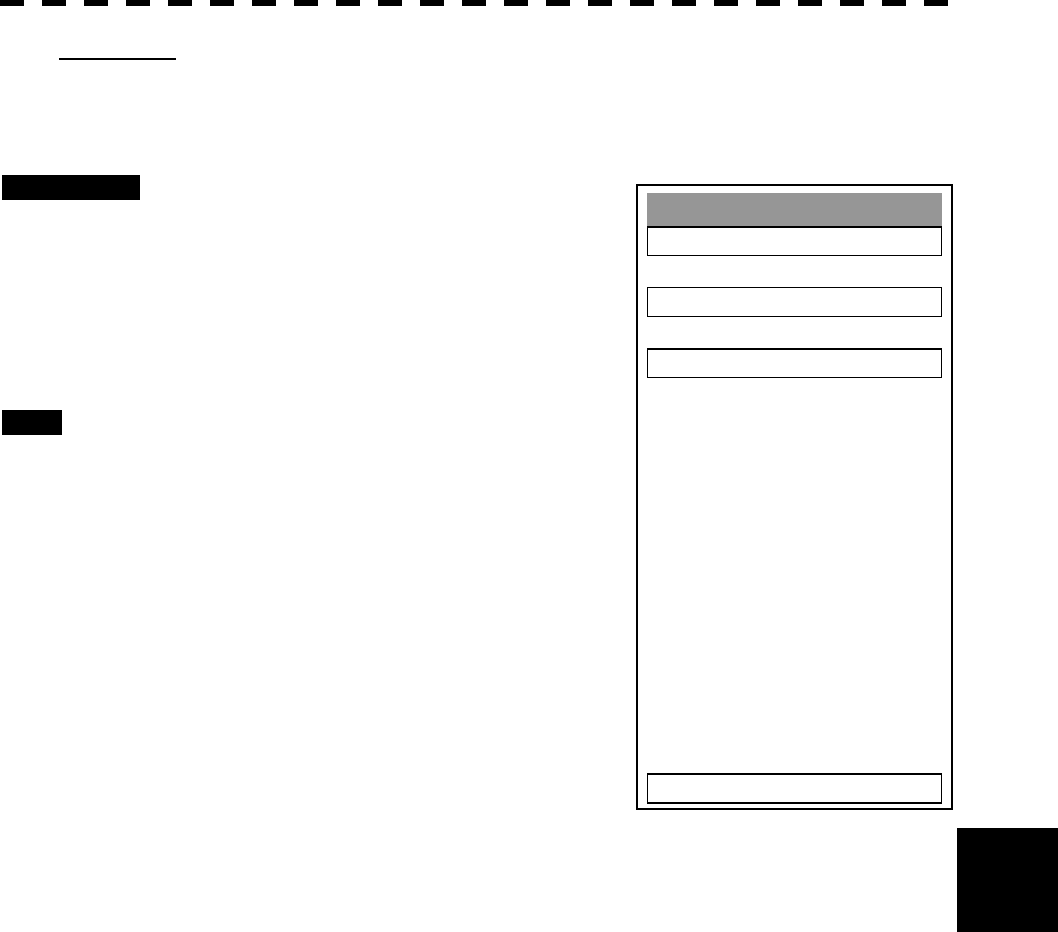
8─10
8
8.1 Performance Check
Keyboard Test
1. Key Test
2. Buzzer Test
3. Li
g
ht
0. EXIT
2) Buzzer Test
Checks for the operation panel buzzer.
Procedures 1 Press [2] key while the Keyboard Test
menu is open.
The buzzer will sound.
2 The buzzer will sound for a given
length of time.
Exit 1 Press [RADAR MENU] key.
The menu will be closed.

8─11
3) Light
Checks for the operation panel light.
Procedures 1 Press [3] key while the Keyboard Test
menu is open.
The brightness of the operation panel is
gradually intensified at four levels.
Exit 1 Press [RADAR MENU] key.
The menu will be closed.
Keyboard Test
1. Key Test
2. Buzzer Test
3. Li
g
ht
0. EXIT
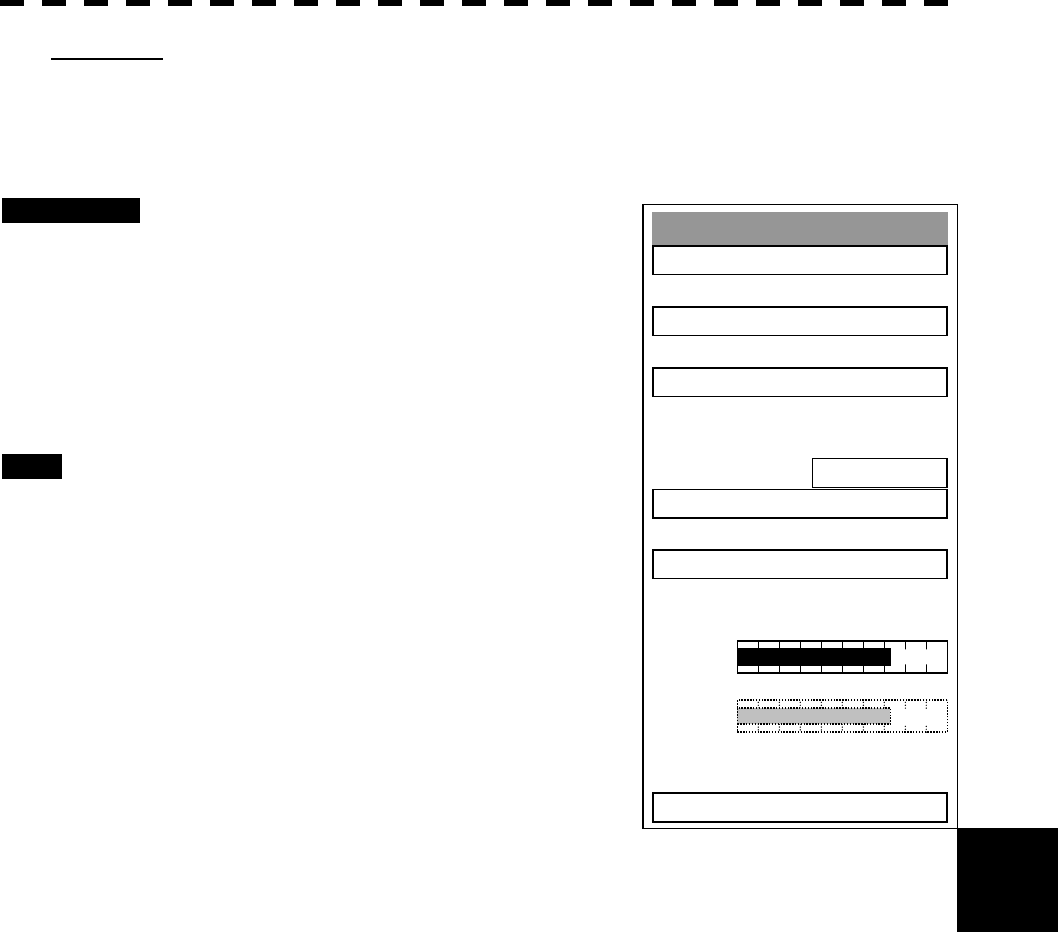
8─12
8
8.1 Performance Check
Test Menu
1. Self Test
2. Monitor Test
3. Keyboard Test
4. PM Display
ON
5. Error Lo
gg
in
g
6. System INFO
0. EXIT
MAGI
PM
[IV] PM Display
Displays the bar indicating the performance monitor status.
* Execution of this item needs a PM unit.
Procedures 1 Press [4] key while the Test Menu is
open, and set PM Display to ON.
The PM bar will appear under the MAGI bar.
The setting of PM Display is switched back and
forth between ON and OFF each time [4] is
pressed.
Exit 1 Press [RADAR MENU] key.
The menu will be closed.
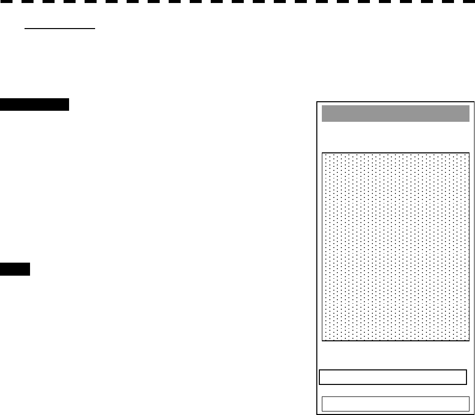
8─13
Error Lo
gg
in
g
0. EXIT
1. All Clear
[V] Error Logging
When a system error occurs, this function shows the error communication line in reverse video. Errors that have
been reset are also displayed in time series.
Procedures 1 Press [5] key while the Test Menu is
open.
The Error Logging Menu will appear.
2 Error logs will be displayed in the
dotted area in the figure at right.
For the display contents, refer to Table 8-2.
Press [1] key to clear all the error logs.
Exit 1 Press [RADAR MENU] key.
The menu will be closed.

8─14
8
8.1 Performance Check
Table 8-2 List of System Error Message (1)
TRX(SSW OFF) Scanner: Safety switch OFF
TRX(AZI) Scanner: BP error
TRX(HL) Scanner: HL error
TRX(MHV) Scanner: Modulator’s high voltage alarm
TRX Scanner: No communication
TRX(DATA) Scanner: Communication software version mismatched, checksum error, or collision
TRX(HEATER) Scanner: Magnetron heater voltage alarm
TRX(REVERSE) Scanner: Reverse rotation
TRX(VIDEO) Scanner: VIDEO error
TRX(TRIGGER) Scanner: TRIGGER error
TRX(FAN 1) Scanner: FAN 1 alarm
TRX(FAN 2) Scanner: FAN 2 alarm
TRX(STAB0) Stabilizer error
TRX(STAB1) Stabilizer error
TRX(STAB2) Stabilizer error
TRX(STAB3) Stabilizer error
TRX(STAB4) Stabilizer error
TRX(STAB5) Stabilizer error
TRX(STAB6) Stabilizer error
TRX(STAB7) Stabilizer error
TRX(STAB8) Stabilizer error
TRX(STAB9) Stabilizer error
TRX(STAB10) Stabilizer error
TRX(STAB11) Stabilizer error
TRX(STAB12) Stabilizer error
TRX(STAB13) Stabilizer error
TRX(STAB14) Stabilizer error
TRX(STAB15) Stabilizer error
TRX(HEATER SUB) Scanner: Magnetron heater voltage alarm (non-selected side of 2 frequencies)
TRX(MHV SUB) Scanner: Modulator’s high voltage alarm (non-selected side of 2 frequencies)
TRX(MOTOR) Scanner: Motor current alarm
PANEL Operation PANEL: Communication error
PANEL(DATA) Operation PANEL: Checksum error
PANEL2 Operation PANEL2: Communication error
PANEL2(DATA) Operation PANEL2: Checksum error
NSK NSK: No communication
NSK(GYRO) NSK: GYRO error (error bit detected)
NSK(DATA) NSK: Checksum error (when receiving data from LOCAL CPU)
LOG NSK: Logging error (error bit detected)
ISW ISW: No communication
ISW(DATA) ISW: Data inconsistency, or checksum error

8─15
Table 8-3 List of System Error Message (2)
DLOG 2-axis log: No communication
DLOG(DATA) 2-axis log: Data error
GPS GPS: No communication
GPS(DATA) GPS: Data error
GPS(STATUS) GPS: Status error
PROC(BOOT) Signal processing unit: Boot error
PROC(INT) Signal processing unit: Interrupt error
PROC(AZI) Signal processing unit: BP error
PROC(HL) Signal processing unit: HL error
ATA(BOOT) ARPA: Boot error
ASIC(INT) Error during interrupt to ASIC1
ASIC1 to RADAR Error during interrupt from ASIC1 to RADAR DSP
RADAR to ASIC2 Error during interrupt from RADAR DSP to ASIC2
ASIC1 to ARPA Error during interrupt from ASIC1 to ARPA DSP
ARPA to ASIC2 Error during interrupt from ARPA DSP to ASIC2
ASIC to LOCAL CPU Error during interrupt from ASIC1 to LOCAL CPU
PROC(VIDEO) VIDEO error
PROC(TRIGGER) Trigger error
AIS AIS: No communication
AIS(DATA) AIS: Communication error
AIS I/F AIS I/F: No communication
AIS I/F(DATA) AIS I/F: Communication error
AIS ALARM *** AIS alarm (Up to 10 alarm messages can be displayed.)
COM1 COM1 port alarm
COM2 COM2 port alarm
COM3 COM3 port alarm
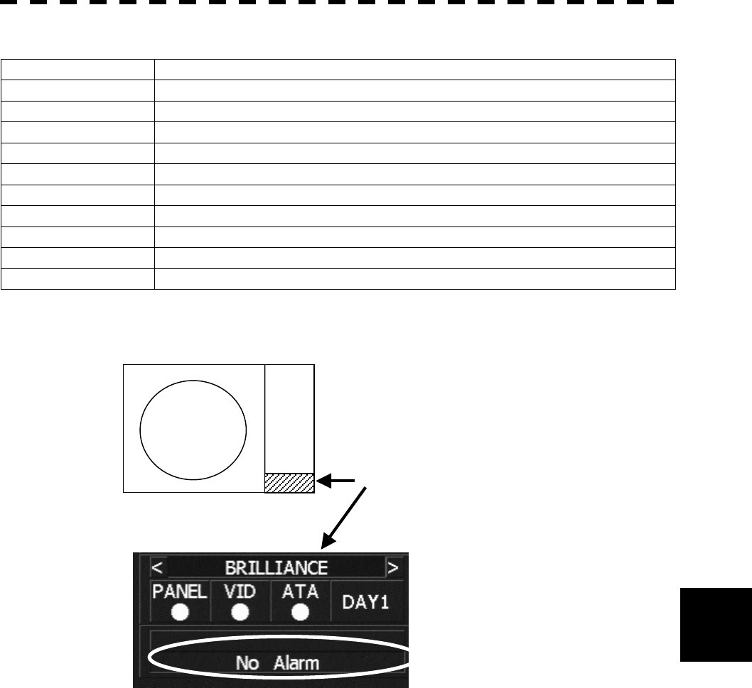
8─16
8
8.1 Performance Check
Table 8-4 List of System Error Message (3)
COM4 COM4 port alarm
HEADING Heading data: No communication
HEADING(DATA) Heading data: Data error
DEPTH Water depth: No communication
DEPTH(DATA) Water depth: Data error
TEMP Water temperature: No communication
TEMP(DATA) Water temperature: Data error
WIND Wind direction/velocity: No communication
WIND(DATA) Wind direction/velocity: Data error
CURRENT Tidal current: No communication
CURRENT(DATA) Tidal current: Data error
Reference: An error message and a warning will appear at the lower right of the radar display.
Position of message or warning indication
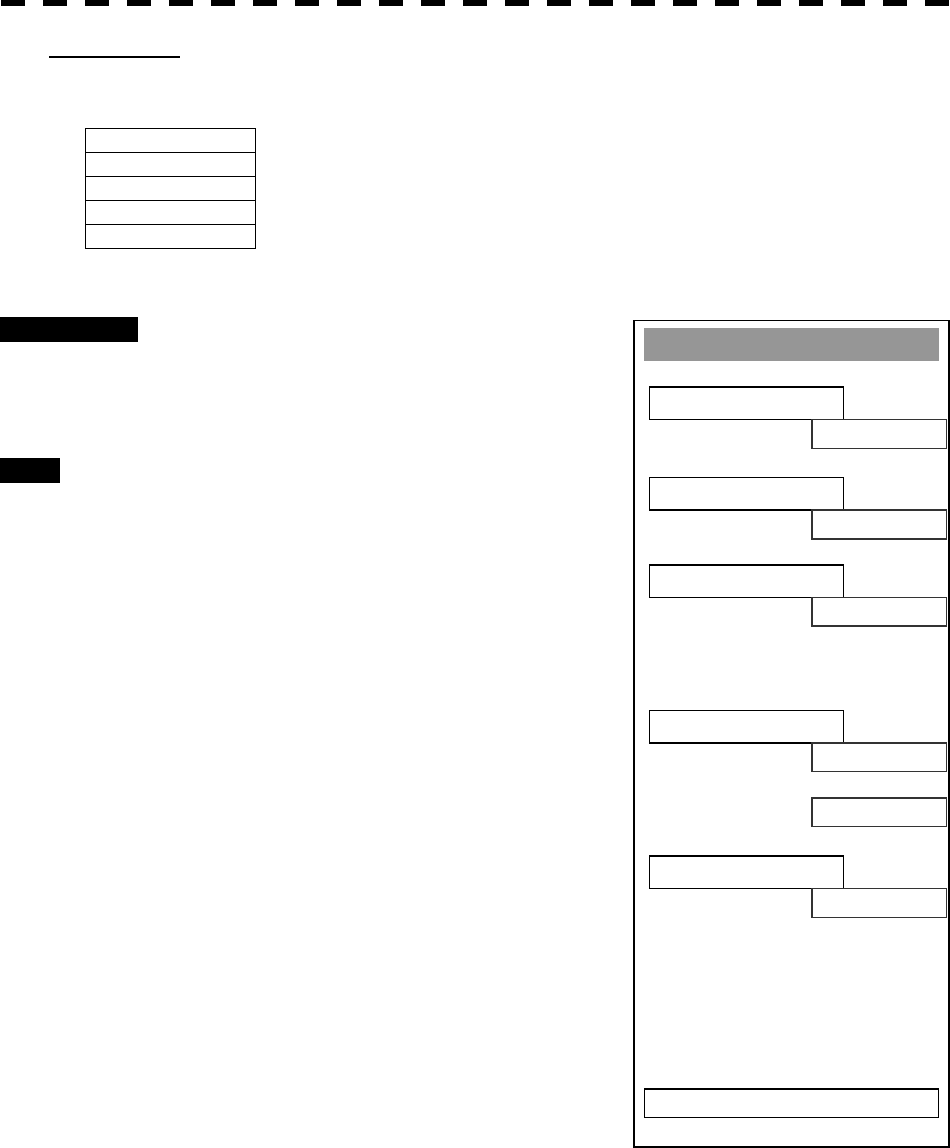
8─17
System INFO
※ Indicator
V
er.xx.xx
EXIT
※ MTR
V
er.xx.xx
※ System No.
No. xxxxx
※TX TIME
Xx hours
X
-BAND
Xx hours
S-BAND
※ Total Time
Xx hours
[VI] System INFO
Displays the current system information.
Indicator Processor software version information
MTR Scanner software version information
System No. System number
TX Time Total transmitting time (Total time during which radar was transmitted)
Tot al Ti me
Total operating time (Total power-on time)
Procedures 1 Press [6] key while the Test Menu is
open.
The System INFO Menu will appear.
Exit 1 Press [RADAR MENU] key.
The menu will be closed.
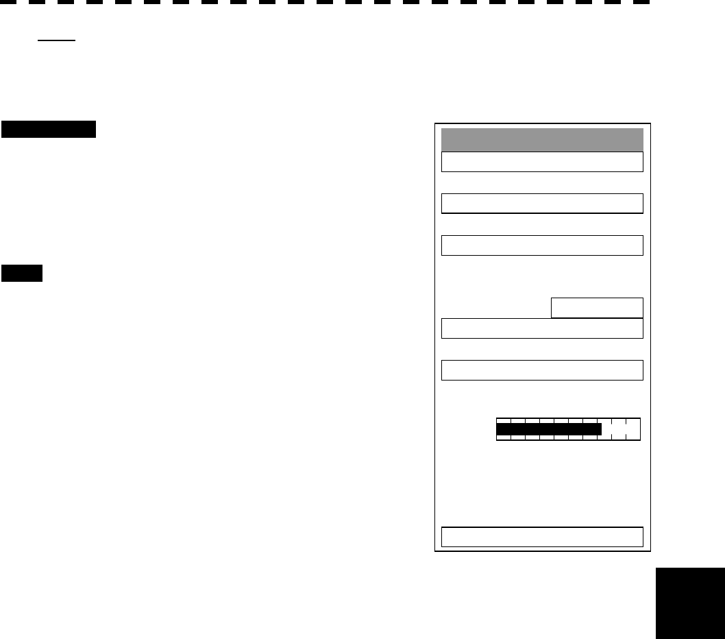
8─18
8
8.1 Performance Check
Test Menu
1. Self Test
2. Monitor Test
3. Keyboard Test
4. PM Display
ON
5. Error Lo
gg
in
g
6. System INFO
0. EXIT
MAGI
[VII] MAGI
Displays the MAGI bar indicating the magnetron current to check.
Procedures 1 Check if the MAGI bar in the Test Menu
reads the value below in a range of 24
NM.
10 kW: 4 to 5 scale marks
25 kW: 5 to 8 scale marks
Exit 1 Press [RADAR MENU] key.
The menu will be closed.

8─19
List of Alarms and other Indications
Table 8-5 List of Gyro Alarms
Message Description
SET GYRO Requires setting of true bearing.
TM RESET Use care of resetting TM.
POSN RESET Change the latitude and longitude sentence.
Table 8-6 List of ARPA Alarms
Message Description
CPA/TCPA Closest approach point/Time for reaching the closest approach point (ARPA)
GZ A target exists in a guard zone.
LOST A target under acquisition cannot be tracked.
Table 8-7 List of Operational Error Messages and Warnings
Message Description
NO HEADING DATA ARPA operation or TM selection when bearing data is invalid
NO POSITION DATA Mark or line input when the latitude and longitude is invalid.
OUT OF RANGE ARPA out of acquisition range
CHANGE RANGE TM selection due to TM-disabled range (96 or 120 nm)
Zooming in a ZOOM-disabled range (0.125 nm)
MAX POINT Tried to enter navigation information beyond the specified.
CAN’T TRANSMIT Tried to transmit within 1 second after standby or when the transmitter-
receiver has any trouble.
INVALID DATA Tried to enter any data beyond its range.
MAX TARGET The maximum number of targets of ARPA is under acquisition.
SELECT STRAIGHT The operator set PM to ON without selecting straight.
NO CARD Card not detected yet
CARD FULL Card capacity insufficient
FORMAT CARD Unformatted card
INVALID CARD Invalid card
READ FAILED Read failure
WRITE FAILED Write failure
DELETE FAILED Deletion failure
FORMAT FAILED Format failure
COPY FAILED Copy failure
NOT ALLOWED General operation error

8─20
8
8.1 Performance Check
Table 8-8 List of Interswitch Alarms and Messages
Message Description
MASTER RANGE CHG The range of the own display unit has changed due to change in the range of the
master display unit.
ALREADY SLECTED Selected the already selected pattern.
ISW END! The switchover of the Interswitch ended normally.
ISW BUSY! Access to the ISW menu was made during interswitching.
TRX ST-BY! The scanner unit is in the standby mode.
ISW STRAIGHT Failed in straight connection when the Interswitch system stops operating.
ISW STAND-BY! The Interswitch recovered normally.
ISW TIME OUT Failed in switching.
ISW ERROR! The interswitch is disabled.
Message set off in a failure of the monitor fan
!
When a failure has occurred in the monitor fan, the monitor displays LCD FAN FAILURE at the center. This display
will disappear by pressing the BRIGHTNESS knob on the monitor. In order to replace the monitor fan, contact our
service department, or the distributor.

8─21
8.2 FAULT FINDING
In case of semiconductor circuits, it is deemed that there are few cases in which the used semiconductor devices
have inferior quality or performance deterioration except due to insufficient design or inspection or by other
external and artificial causes. In general, the relatively many causes are disconnection in a high-value resistor
due to moisture, a defective variable resistor and poor contact of a switch or relay.
Some troubles are caused by defective parts, imperfect adjustment (such as tuning adjustment) or insufficient
service (such as poor cable contact). It will also be effective to check and readjust these points.
Melted fuses are caused by any clear cause. When a fuse is replaced, it is necessary to check the related
circuits even if there is no trouble. In checking, note that there is some dispersion in the fusing characteristics.
Table 8-12 shows a list of fuses used in the equipment.
Table 8-12 Fuse List
Location Parts No. Current Rating Protection Circuit Type
Transmitter-receiver Unit F1 1A Rectifier circuit PC1001 MF51NN-1A
Display Unit F2 to F3 10A I/O circuit PC410 MF60NR-10A
LOG.NSK circuit F1 to F4 0.5A LOG.NSK circuit PC4201 MF60NR-0.5A
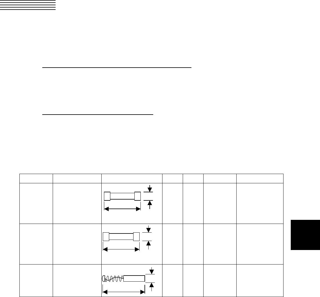
8─22
8
8.3 TROUBLE SHOOTING
As this radar equipment includes complicated circuits, it is necessary to request a specialist engineer for repair
or instructions for remedy if any circuit is defective.
There are also troubles by the following causes, which should be referred to in checking or repair work.
1 Poor Contact in Terminal Board of Inter-Unit Cables
a) Poor contact in terminal board
b) The cable end is not fully connected, that it, contacted with earthed another terminal.
c) Disconnected cable wire
2 Poor Contact of Connector within Unit
Reference: This radar equipment is provided with 8-13 standard spares.
Table 8-13 Spares (7ZXRD0014, JMA-5310-6, 7ZXRD0015, JMA-5320-7/9/6HS, JMA-5330-12)
7ZXRD0014
Name Type/Code Shape (mm) In use Spare Parts No. Location
Fuse ST4-5AN1
(5ZFCA00050)
1 3 F2
Inside processing
unit
Fuse ST6-8AN1
(5ZFCA00052)
1 3 F3
Inside processing
unit
Motor
brush
54583-01
(BRSW00101)
1 2 – Scanner monitor
31.8
Φ6.35
31.8
Φ6.35
32.0
Φ8.0
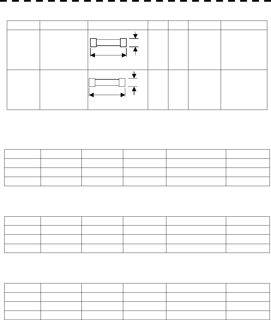
8─23
7ZXRD0015
Name Type/Code Shape (mm) In use Spare Parts No. Location
Fuse ST6-10AN1
(5ZFCA00053)
1 3 F2
Inside processing
unit
Fuse ST6-10AN1
(5ZFCA00053)
1 3 F3
Inside processing
unit
Table 8-14 Special Parts
[I] JMA-5310-6
Parts No. Name Type Manufacturer Location Code
V101 Magnetron MSF1425B NJRC Scanner 5VMAA00051
A101 Circulator FCX68 Toshiba Scanner 6AJRD00001
A102 Diode Limiter NJS6930 NJRC Scanner 5EZAA00024
[II] JMA-5320-7/9/6HS
Parts No. Name Type Manufacturer Location Code
V1 Magnetron M1568B(J) NJRC Scanner 5VMAA00082
A101/A102 Circulator FCX68 Toshiba Scanner 6AJRD00001
A303 Diode Limiter NJS6930 NJRC Scanner 5EZAA00024
[III] JMA-5330-12
Parts No. Name Type Manufacturer Location Code
V1 Magnetron M1302 NJRC Scanner 5VMAA00032
A101 Circulator NJC3320 NJRC Scanner 5AJBV00004
A303 TRHPL TL378A NJRC Scanner 5VLAA00032
31.8
Φ6.35
31.8
Φ6.35

8─24
8.3 Trouble Shooting
8
Table 8-15 Circuit Block to be Repaired (JMA-5310-6)
Location Circuit Block Type Remarks
Scanner Motor with gear CBP-139 DC brush motor (ordinary)
Scanner Modulator CPA-248 Excluding Magnetron
Scanner Receiver NRG-226 Including CAE-475-1
Scanner Power supply circuit CBD-1645
Processor Radar processing circuit CDC-1198 PC440
Processor DSP circuit (ARPA) CDC-1186A PCI (Option)
Processor DSP circuit (MARPA) CDC-1186B PCI (Option)
Processor NSK/LOG I/F circuit CMJ-304C PC4201 (Option)
Processor Terminal board circuit CQD-1937 PC430
Processor I/O circuit CQC-1075 PC410
Processor Power circuit CBD-1655 PC510
Operation panel unit Operation panel unit CCK-905 PC600
Operation panel unit PS2 connector circuit CQC-1095 PC610
Multi-function control Operation circuit CCK-914 PC601 (Option)
Multi-function control PS2 connector circuit CQC-1109 PC610 (Option)
Junction Box Interface circuit CMH-1994 PCI (Option)
Display Monitor fan 109R0812H4D01

8─25
Table 8-16 Circuit Block to be Repaired (JMA-5320-7/9/6HS)
Location Circuit Block Type Remarks
Scanner Motor with gear H-7BDR0044 DC brushless motor (ordinary
speed)
Scanner Motor with gear H-7BDRD0045 DC brushless motor (high speed)
Scanner Modulator NMA-499-1
Including CPA-209-1
Including CFR-161
Excluding Magnetron
Scanner Receiver NRG-154 Including CAE-344
Scanner Power supply circuit CBD-1682
Scanner T/R control circuit CMC-1205
Scanner Motor power supply circuit CBH-3
Scanner Motor power supply circuit CSA-283
Processor Radar processing circuit CDC-1198 PC440
Processor DSP circuit (ARPA) CDC-1186A PCI (Option)
Processor DSP circuit (MARPA) CDC-1186B PCI (Option)
Processor NSK/LOG I/F circuit CMJ-304C PC4201 (Option)
Processor Terminal board circuit CQD-1937 PC430
Processor I/O circuit CQC-1075 PC410
Processor Power circuit CBD-1655 PC510
Operation panel unit Operation panel unit CCK-905 PC600
Operation panel unit PS2 connector circuit CQC-1095 PC610
Multi-function control Operation circuit CCK-914 PC601 (Option)
Multi-function control PS2 connector circuit CQC-1109 PC610 (Option)
Display Monitor fan 109R0812H4D01

8─26
8.3 Trouble Shooting
8
Table 8-17 Circuit Block to be Repaired (JMA-5330-12)
Location Circuit Block Type Remarks
Scanner Motor with gear MPEM30030 220VAC 3-phase
Scanner Motor with gear MPEM30110 220VAC 3-phase
Scanner Motor with gear MPEM30092 110VAC 1-phase
Scanner Modulator NMA-534-1
Including CPA-209
Including CFR-161
Excluding Magnetron
Scanner Receiver NRG-222
Including CAE-344-4
Including CAF-424
Including CGH-205
Including CBD-1274
Scanner T/R control circuit CMC-1205 PC1101
Scanner Power supply circuit CHD-1682
Processor Signal processing circuit CDC-1198 PC440
Processor DSP circuit (ARPA) CDC-1186A PCI (Option)
Processor DSP circuit (MARPA) CDC-1186B PCI (Option)
Processor NSK/LOG I/F circuit CMJ-304C PC4201 (Option)
Processor Terminal board circuit CQD-1937 PC430
Processor I/O circuit CQC-1075 PC410
Processor Power circuit CBD-1655 PC510
Operation panel unit Operation panel unit CCK-905 PC600
Operation panel unit PS2 connector circuit CQC-1095 PC610
Multi-function control Operation circuit CCK-914 PC601 (Option)
Multi-function control PS2 connector circuit CQC-1109 PC610 (Option)
Display Monitor fan 109R0812H4D01
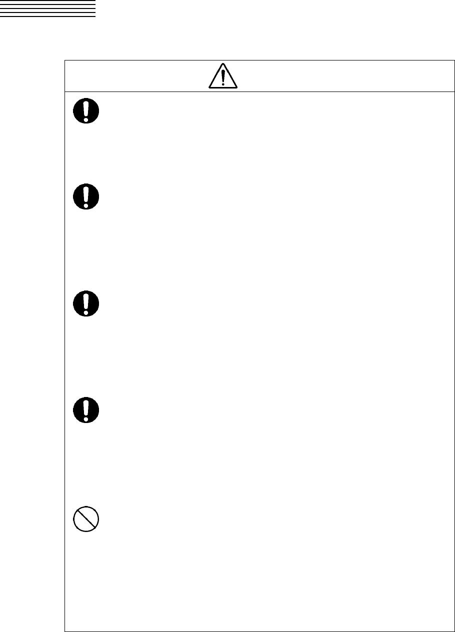
8─27
8.4 REPLACEMENT OF MAJOR PARTS
CAUTION
Turn off the main power source before replacing
parts. Otherwise, an electric shock or trouble
may be caused.
Before replacing the magnetron, turn off the main
power source and wait for 5 minutes or more until
the high voltage circuits are discharged.
Otherwise, an electric shock may be caused.
Take off your wrist watch when bringing your
hands close to the magnetron.
Otherwise, your watch may be damaged because
the magnetron is a strong magnet.
Two or more persons shall replace the liquid
crystal monitor.
If only one person does this work, he may drop the
LCD, resulting in injury.
Even after the main power source is turned off,
some high voltages remain for a while.
Do not contact the inverter circuit in the LCD with
bare hands. Otherwise, an electric shock may be
caused.

8─28
8.4 Replacement of Major Parts
8
Parts Required for Periodic Replacement
Here are parts required for periodic replacement
Part name Interval
1. Magnetron 4000 hours
2. Motor 10000 hours
3. LCD backlight 50000 hours
4. Fan motor 20000 hours
5. Backup battery 3 years
Replacement of magnetron (V1/V201)
Remove the shield cover of the modulator and check that no charge remains in the high-voltage modulator
circuit. Then, remove the socket of the magnetron. The magnetron can be demounted by removing the
screws fixing it. When mounting a new magnetron, do not touch the magnet with a screwdriver or put it on an
iron plate. After replacement, connect the lead wire correctly.
Handling of Magnetron under Long-Time Storage
The magnetron that has been kept in storage for a long time may cause sparks and operate unstably when its
operation is started. Perform the aging in the following procedures:
(1) Warm up the cathode for a longer time than usually. (20 to 30 minutes in the STBY state.)
(2) Start the operation from the short pulse range and shift it gradually to the longer pulse ranges. If the
operation becomes unstable during this process, return it to the standby mode immediately. Keep the
state for 5 to 10 minutes until the operation is restarted.
Replacement of TRHPL (A303)(JMA-5330-12)
Remove the 4 screws fixing the TRHPL with receiver and remove the TRHPL. When mounting the TRHPL,
take care of the mounting direction and mount it in the arrow direction facing it the receiver front end.
Replacement of Diode Limiter (A303)(JMA-5310-6, JMA-5320-7/9/6HS)
Remove the 4 screws fixing the receiver. Remove the 4 screws fixing the diode and the limiter, and remove
diode limiter. When mounting the diode limiter, take care of the mounting direction and mount it in the arrow
direction facing it the receiver front end.
Connect the wiring in the same way as before the replacement.

8─29
Replacement of LCD Monitor
1 JMA-5310-6, JMA-5320-7/9/6HS, JMA-5330-12 (Display Unit: NCD-4510)
(1) Disconnect the cables from the connectors “VIDEO” and “VIDEO DC OUT” on the rear of the processor.
(2) Softly place the LCD monitor on a desk covered with a soft cloth.
(3) Attach a new LCD monitor in the reverse sequence as described above.
l When replacing the LCD monitor, which is easily
broken by a little impact, handle it carefully and do
not hit any article against it or put it on a hard article.
Attention
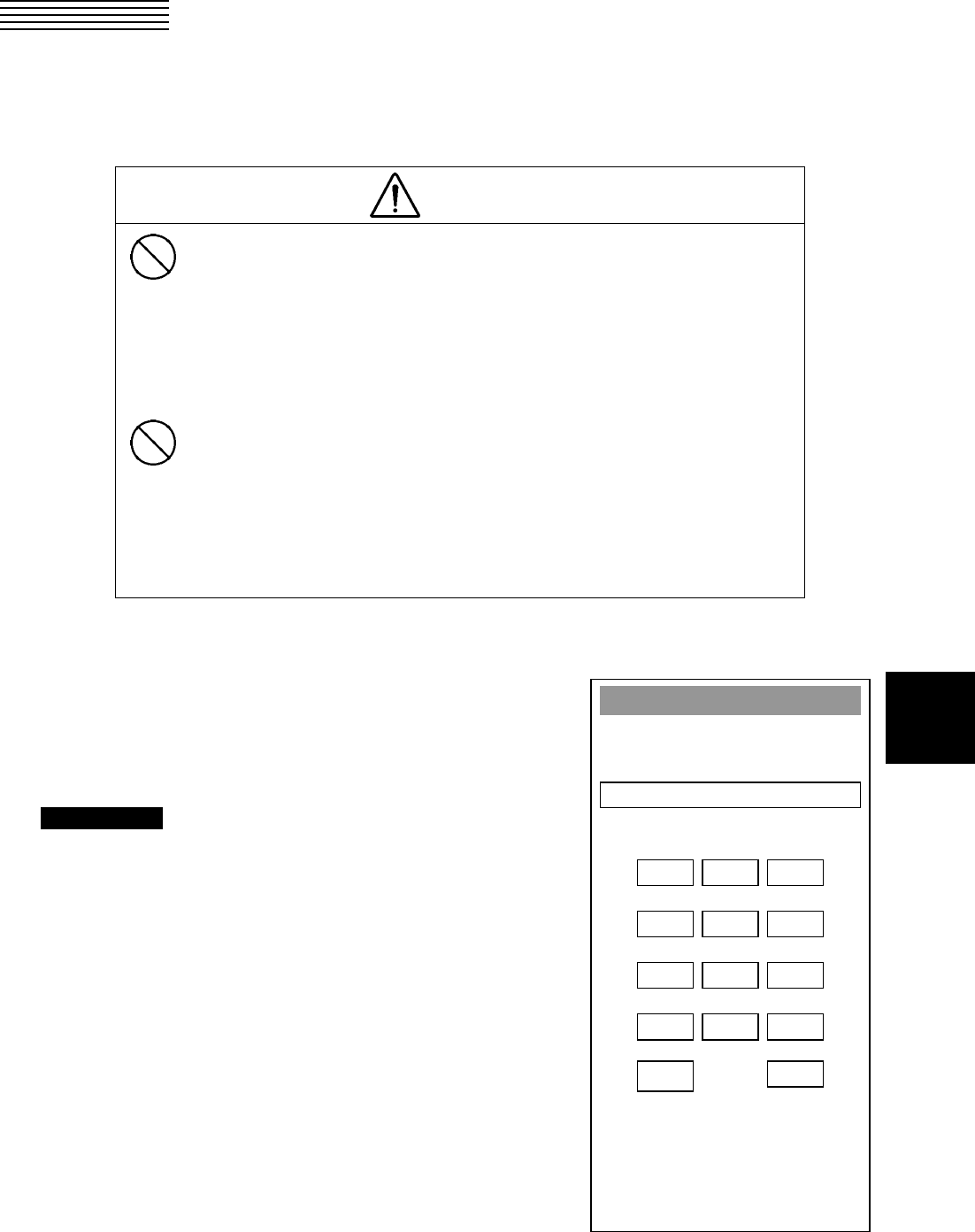
8─30
8
Code Input
Press “0” and “ENT”
to Adjust Menu
1 2 3
4 5 6
7 8 9
+ 0 -
CL
R
ENT
8.5 ADJUSTMENTS
This section describes the electrical adjustments of the equipment as the adjustment procedures to be carried
out by service persons at the time of installation.
CAUTION
Do not carry out the adjustments of the equipment
except authorized service persons. If wrong
setting is carried out, this may cause unstable
operation.
Do not carry out the adjustments during
navigation. Otherwise, the radar performance
may be affected, resulting in an accident or
trouble.
Tuning, bearing and range adjustments can be made from the operation panel. Start the adjustment mode in
the following procedures.
How to open the Adjust Menu
Procedures 1 Continue to press [RADAR MENU]
key.
The Code Input Menu will appear.
2 Press [0] key.
3 Move the cursor onto the “ENT”
button in the Code Input menu, and
press [ENT] key.
The Adjust Menu will appear.
8─31
4 Press [1] key.
The Equipment Setup Menu will appear.
Exit 1 Press [RADAR MENU] key.
The Main Menu will reappear.
A
d
j
ust Menu
1. Equipment Setup
2. Maintenance Menu
9. SP/ATA INIT Setup
0. EXIT
Equipment Setup
1. Bearin
g
Ad
j
ustment
0.0°
2. Ran
g
e Ad
j
ustment
0
0
0. EXIT
3. Tune Ad
j
ustment
4. TRX Settin
g
5. COM Port Settin
g
6. NAV Settin
g
7. Sector Blank
9. Lan
g
ua
g
e
ENGLISH
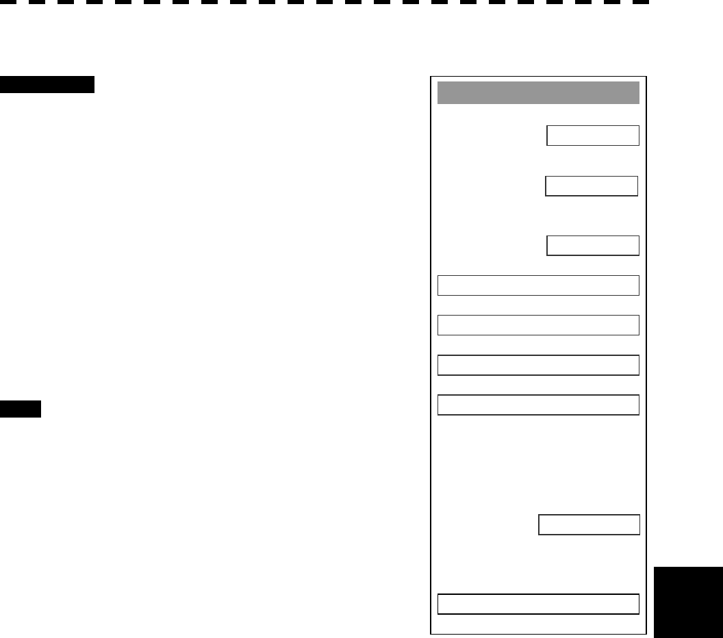
8─32
8.5 Adjustments
8
Tuning Adjustment
Procedures 1 Open the Equipment Setup Menu.
2 Press [3] key.
The Code Input Menu will appear.
3 Using numeric pad, enter the value and
then press “ENT” button, and press
“EXIT” button to determine the value.
The multi-function control can also be used to
enter the value.
4 Repeat Step 3, and adjust the
bar-graph of the tuning indicator on
the upper left of the display so that it
becomes the longest.
Exit 1 Press [RADAR MENU] key.
The Main Menu will reappear.
Equipment Setup
1. Bearin
g
Ad
j
ustment
0.0°
2. Ran
g
e Ad
j
ustment
0
0
0. EXIT
3. Tune Ad
j
ustment
4. TRX Settin
g
5. COM Port Settin
g
6. NAV Settin
g
7. Sector Blank
9. Lan
g
ua
g
e
ENGLISH
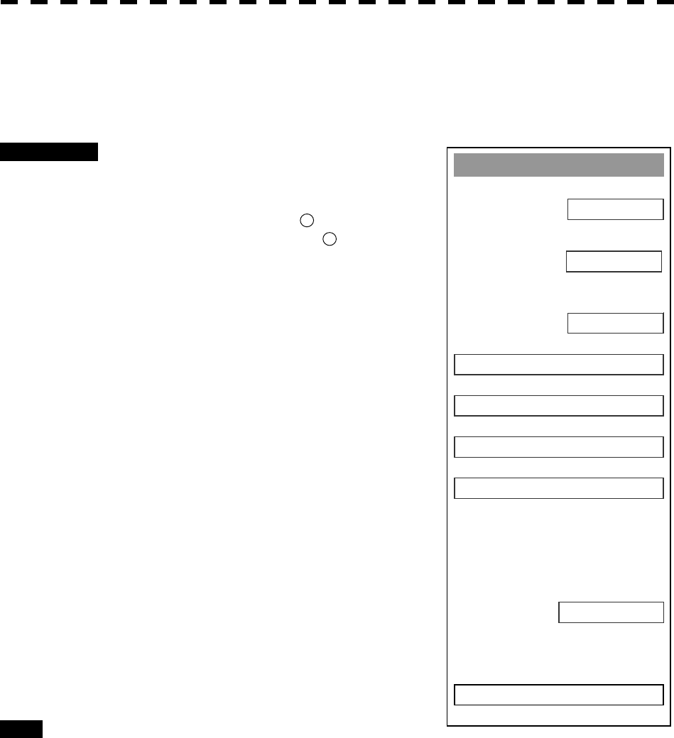
8─33
Bearing Adjustment
Adjust the bearing so that bearing of the target measured with the ship’s compass matches that of the target
echo on the radar display.
Procedures 1 Press AZI MODE to select the relative
bearing presentation [H UP] mode. Set
Image Processing to OFF.
[AZI MODE] ® Button 5on the Radar Menu
Image Processing ® Button 12 in the Radar
Menu
2 Measure the bearing of an adequate
target (for example, a ship at anchor, a
breakwater or a buoy) relative to own
ship’s heading.
3 Open the Equipment Setup Menu.
4 Press [1] key.
The Code Input Menu will appear.
5 Using numeric key, enter the value and
then press “ENT” button, and press
“EXIT” button to determine the value.
The multi-function control can also be used to
enter the value.
6 Repeat Step 5 above, and adjust to
display the target measured in Step 2
to the measured bearing.
Exit 1 Press [RADAR MENU] key.
The Main Menu will reappear.
Equipment Setup
1. Bearin
g
Ad
j
ustment
0.0°
2. Ran
g
e Ad
j
ustment
0
0
0. EXIT
3. Tune Ad
j
ustment
4. TRX Settin
g
5. COM Port Settin
g
6. NAV Settin
g
7. Sector Blank
9. Lan
g
ua
g
e
ENGLISH
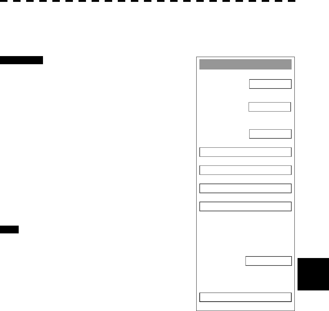
8─34
8.5 Adjustments
8
Range Adjustment
Adjust the range so that the range of the target on the radar video is indicated correctly.
Procedures 1 Search the radar display for a target of
which range is already known.
2 Open the Equipment Setup Menu.
3 Press [2] key.
The Code Input Menu will appear.
4 Using numeric pad, enter the value and
then press “ENT” button, and press
“EXIT” button to determine the value.
The multi-function control can also be used to
enter the value.
5 Repeat step 4, and adjust until the
target range measured in step 1 and
the range on the radar display become
identical.
Exit 1 Press [RADAR MENU] key.
The Main Menu will reappear.
Equipment Setup
1. Bearin
g
Ad
j
ustment
0.0°
2. Ran
g
e Ad
j
ustment
0
0
0. EXIT
3. Tune Ad
j
ustment
4. TRX Settin
g
5. COM Port Settin
g
6. NAV Settin
g
7. Sector Blank
9. Lan
g
ua
g
e
ENGLISH
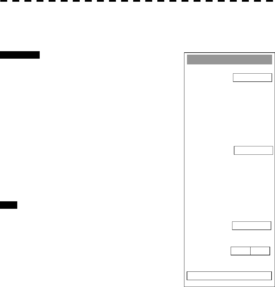
8─35
Antenna Height Adjustment
Set the antenna height above the sea level, but change this setting carelessly.
Procedures 1 Measure the height from the sea level to
the antenna in advance.
2 Open the Equipment Setup Menu.
3 Press [4] key.
The TRX Setting Menu will appear.
4 Press [1] key.
The Antenna Height Set Value window will
appear.
5 Select the antenna height measured in
step 1 from the pull-down menu by
pressing the numeric key [1] to [4].
The antenna height will be determined.
Exit 1 Press [RADAR MENU] key.
The Main Menu will reappear.
TRX Settin
g
1. Antenna Hei
g
ht
5-10m
8. Antenna Location
0
4. PM Ad
j
ustment
2048
7. Output Pulse
0m 0m
0. EXIT
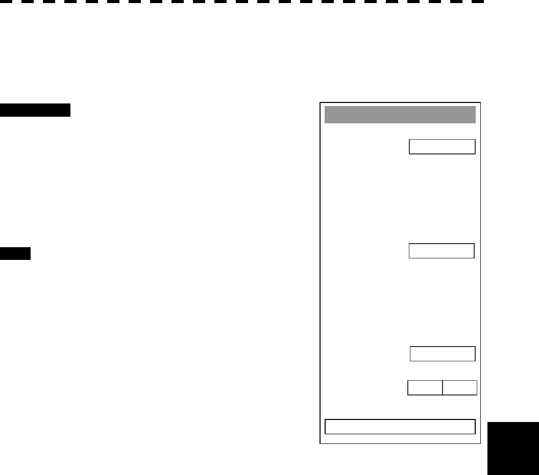
8─36
8.5 Adjustments
8
Bearing Pulse Output Adjustment (Output Pulse)
Set the output value of bearing pulse. This radar can set the output value to 2048 pulses and 4096 pulses.
This setting is allowed only when a 25 kw antenna is used.
Procedures 1 Open the Equipment Setup Menu.
2 Press [4] key.
The TRX Setting Menu will appear.
3 Press [7] key.
4 Select a set value to be used.
Exit 1 Press [RADAR MENU] key.
The Main Menu will reappear.
TRX Settin
g
1. Antenna Hei
g
ht
5-10m
0. EXIT
0
4. PM Ad
j
ustment
0
7. Output Pulse
2048
8. Antenna Location
0m 0m
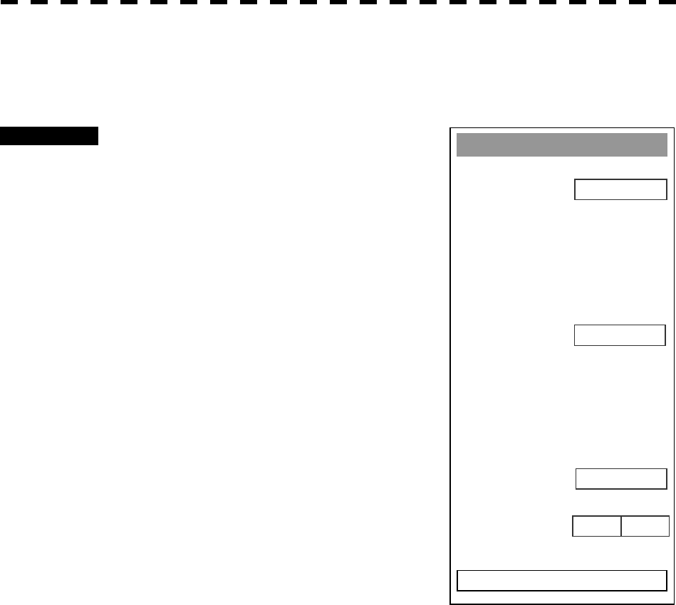
8─37
Scanner Antenna Location Adjustment (Antenna Location)
Set the position at which the scanner is installed.
Procedures 1 Open the Equipment Setup Menu.
3 Press [4] key.
The TRX Setting Menu will appear.
4 Press [8] key.
The Antenna Location Menu will appear.
TRX Settin
g
1. Antenna Hei
g
ht
5-10m
0. EXIT
0
4. PM Ad
j
ustment
7. Output Pulse
2048
8. Antenna Location
0m 0m
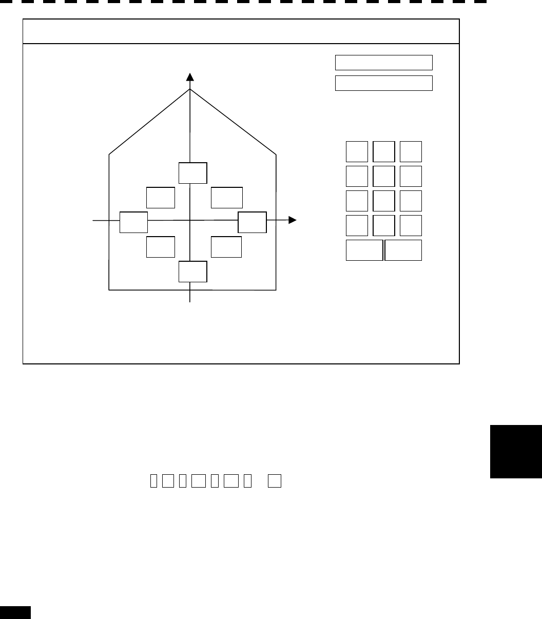
8─38
8.5 Adjustments
8
5 Enter two values, a and b.
With a > 0, the antenna is installed in the ship’s heading direction.
With a < 0, the antenna is installed in the ship’s stem direction.
With b > 0, the antenna is installed in the ship’s starboard side direction.
With b < 0, the antenna is to be installed in the ship’s port side direction.
Pressing T, LT, L, LB, B, RB, R, or RT in the own ship gives ±sign, appropriate to the
place, to values a and b.
Press CLR for cancellation. Press ENT to determine the value.
6 Press [0] key.
Entry will end.
Exit 1 Press [RADAR MENU] key.
The Main Menu will reappear.
b
aa: 35m
b: -5m
4 5 6
1 2 3
7 8 9
- 0
+
CL
R
ENT
(-500 to 500 [m])
A
ntenna Location
1. SET
0. EXIT
Set Location Rou
g
hly
T
LT
L
LB
B
RT
R
RB
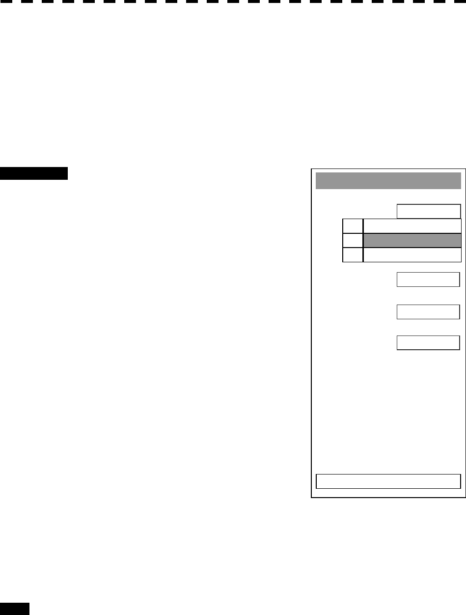
8─39
Baud Rate
1. COM1 (GPS)
4800bps
2. COM2 (PC)
4800bps
384000bp
0. EXIT
3. COM3 (NAV1)
4800bps
4. COM4 (NAV2)
5. COM5 (COMPASS)
4800bps
1. 1200bps
2. 4800bps
3. 38400bps
COM Port Setting
External sensor signals are to be entered to this radar via a COM port. This radar has five COM ports. Input
of signals from sensors or output of signals to sensors needs to adjust the COM port in accordance with the
sensors.
[I] Baud Rate Setting
Set the baud rate of the signal to be entered into the COM port.
Procedures 1 Open the Equipment Setup Menu.
2 Press [5] key.
The COM Port Setting Menu will appear.
3 Press [1] key.
The Baud Rate Setting Menu will appear.
4 Select the port number you want to set,
pressing the numeric keys [1] to [5].
The Baud Rate Selection menu will appear.
5 In the selection menu, select the baud
rate you want to set, pressing the
numeric key.
Selection value
1. COM1 (GPS): 1200/4800/*38400 bps
2. COM2 (PC): 1200/4800/
38400/115200 bps
3. COM3 (NAV1): 1200/4800/38400 bps
4. COM4 (NAV2): 1200/4800/*38400 bps
5. COM5 (COMPASS): 4800/38400 bps
* If COM1/COM4 is set to 38400 bps, signals
can only be transmitted. The baud rate for reception can be set to up to 4800 bps.
COM5 can be used for receive port only. It is dedicated for COMPASS signal. This
means that the port is unavailable for other signals.
The GPS, PC, NAV1, NAV2, COMPASS in the parentheses are the standard ports
connecting to the external sensors.
Exit 1 Press [RADAR MENU] key.
The Main Menu will reappear.
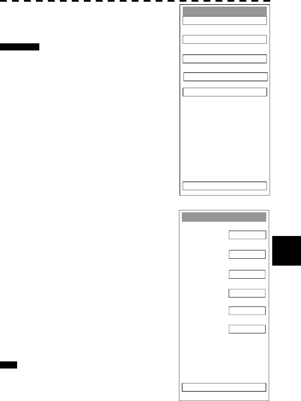
8─40
8.5 Adjustments
8
GPS (LL/COG/SOG)
1. GG
A
USE
2. RMC
USE
USE
0. EXIT
3. RM
A
USE
4. GNS
5. GLL
6. VTG
USE
USE
[II] Reception Sentence Setting (RX Sentence)
Set signal sentences to be received from sensors.
Procedures 1 Open the Equipment Setup Menu.
2 Press [5] key.
The COM Port Setting Menu will appear.
3 Press [2] key.
The RX Sentence Menu will appear.
4 Select the signal you want to set,
pressing the numeric keys [1] to [3].
The Setting Menu for each signal will appear.
Settable signal
1. GPS (LL/COG/SOG)
2. GPS (WPT/Time)
3. Depth
4. Wind
5. Current
¯
¯
5 Select whether or not you want to use
sentence for the signal.
Types of sentences to be used
GPS (LL/COG/SOG): GGA/RMC/RMA/GNS/
GLL/VTG
GPS (WPT/Time): GGA/RMC/RMB/
BWC/BWR/ZDA
Depth: DPT/DBK/DBT/DBS
Wind: MWV/MWD
Current: CUR
After having selected a signal, choose the
number of the sentence for which you want to
set whether or not it is used, pressing the
numeric key.
As concerns current, set data set number and
layer number of CUR sentence.
Exit 1 Press [RADAR MENU] key.
The Main Menu will reappear.
RX Sentence
1. GPS (LL/COG/SOG) >
2. GPS (WPT/Time) >
0. EXIT
3. Depth >
5. Current >
4. Wind >
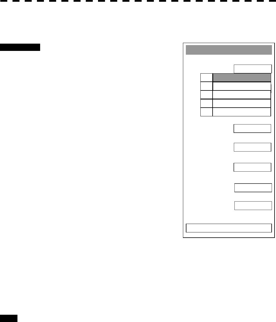
8─41
[III] Transmission Port Setting (TX Port)
Set the number of the port via which signals are transmitted to sensors.
Procedures 1 Open the Equipment Setup Menu.
2 Press [5] key.
The COM Port Setting Menu will appear.
3 Press [3] key.
The TX Port Menu will appear.
4 Select the signal you want to set,
pressing the numeric keys [1] to [8].
The Output Port Setting Menu for each signal
will appear.
Settable signals
1. TTM (ATA Target)
2. TLL (ATA Target)
3. OSD
4. RSD
5. ALR
6. AIS
7. TTM (AIS Target)
8. TLL (AIS Target)
5 Select which port you want to use for
output.
Types of ports to be used
1. OFF
2. COM1 (GPS)
3. COM2 (PC)
4. COM3 (NAV1)
5. COM4 (NAV2)
Select the number of the port to be used, pressing the numeric key.
Exit 1 Press [RADAR MENU] key.
The Main Menu will reappear.
* Note that, if you set COM1 and COM4 for transmission, they cannot be used as reception ports.
TX Port
1. TTM (ATA Tar
g
et)
2. TLL(ATA Target)
0. EXIT
3. OSD
OFF
OFF
OFF
OFF
OFF
A
UTO
4. RSD
5.
A
L
R
6.
A
IS
OFF
7. TTM (AIS Tar
g
et)
OFF
8. TTL (AIS Tar
g
et)
1. OFF
2. COM1 (GPS)
3. COM2 (PC)
4. COM3 (NAV1)
5. COM4 (NAV2)
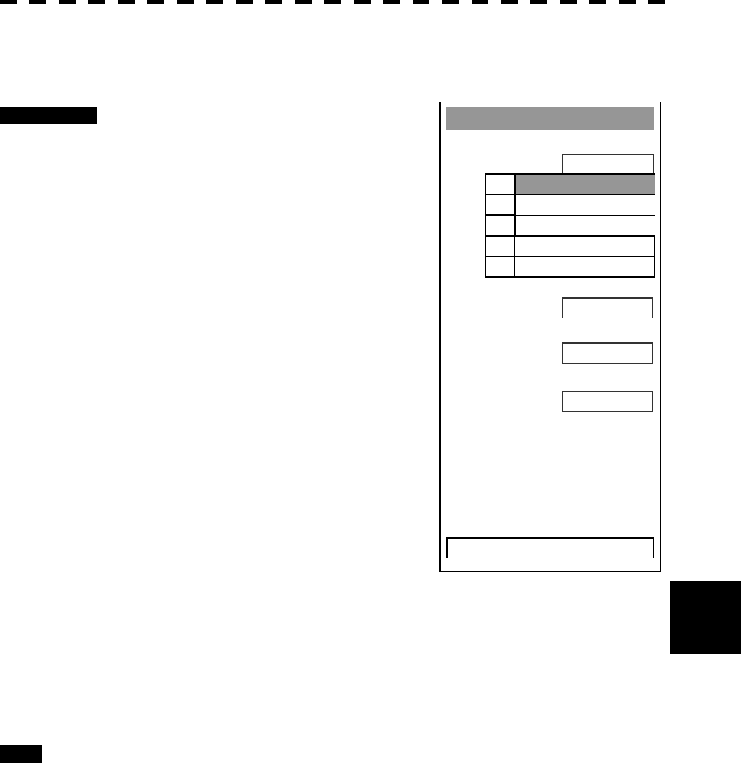
8─42
8.5 Adjustments
8
RX Port
1. GPS
2. DLOG
0. EXIT
3. Depth
A
UTO
A
UTO
OFF
A
UTO
A
UTO
A
UTO
4. Temperature
5. Wind
6. Current
1.
A
UTO
2. COM1 (GPS)
3. COM2 (PC)
4. COM3 (NAV1)
5. COM4 (NAV2)
[IV] Reception Port Setting (RX Port)
Set the number of the port via which signals are received from sensors.
Procedures 1 Open the Equipment Setup Menu.
2 Press [5] key.
The COM Port Setting Menu will appear.
3 Press [4] key.
The RX Port Menu will appear.
4 Select the signal you want to set,
pressing the numeric keys [1] to [6].
The Reception Port Setting Menu for each
signal will appear.
Settable signals
1. GPS
2. DLOG
3. Depth
4. Temperature
5. Wind
6. Current
5 Select which port you want to use for
output.
Types of ports to be used
1. AUTO
2. COM1 (GPS)
3. COM2 (PC)
4. COM3 (NAV1)
5. COM4 (NAV2)
* For AUTO, the initial value will be selected.
Select the number of the port to be used, pressing the numeric key.
Exit 1 Press [RADAR MENU] key.
The Main Menu will reappear.
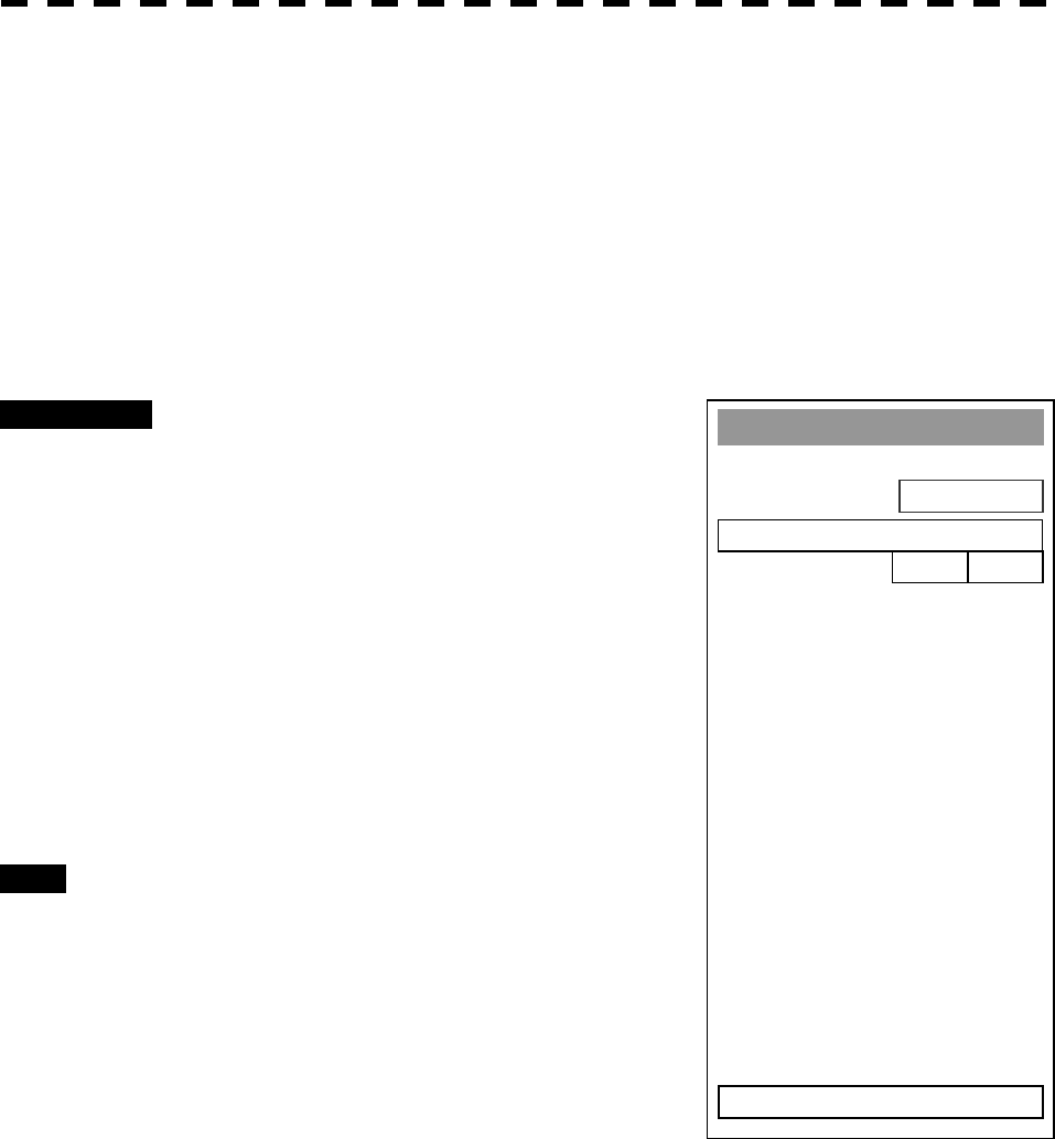
8─43
NAV Settin
g
1. Sel NAV Equipment
INT GPS
2. GPS ANT. Location
0. EXIT
0m 0m
Navigator Setting (NAV Setting)
JRC’s GPS adopts connector connections on the backside of the processing unit. However, a GPS produced
by other manufacturers uses terminal strip inputs in the processing unit. To do so, input area settings are
needed. In addition, GPS antenna installation position can be set.
[1] Navigator Setting (Sel NAL Equipment)
Set whether the navigator to be connected is to be installed inside (JRC’s GPS) or outside (other
manufacturer’s GPS).
Procedures 1 Open the Equipment Setup Menu.
2 Press [6] key.
The NAV Setting Menu will appear.
3 Press [1] key.
Switching between inside and outside is done
each time the key is pressed.
INT GPS: JRC’s GPS (connection on the
backside of the processing unit)
EXT: Other manufacturer’s GPS (Terminal
strip connection inside the processing
unit)
Exit 1 Press [RADAR MENU] key.
The Main Menu will reappear.
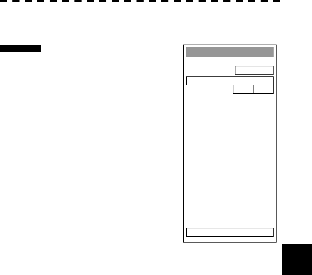
8─44
8.5 Adjustments
8
NAV Settin
g
1. Sel NAV Equipment
INT GPS
2. GPS ANT. Location
0. EXIT
0m 0m
[II] GPS Antenna Location Setting (GPS ANT. Location)
Set the GPS antenna installation position.
Procedures 1 Open the Equipment Setup Menu.
2 Press [6] key.
The NAV Setting Menu will appear.
3 Press [2] key.
The GPS Antenna Location Menu will appear.
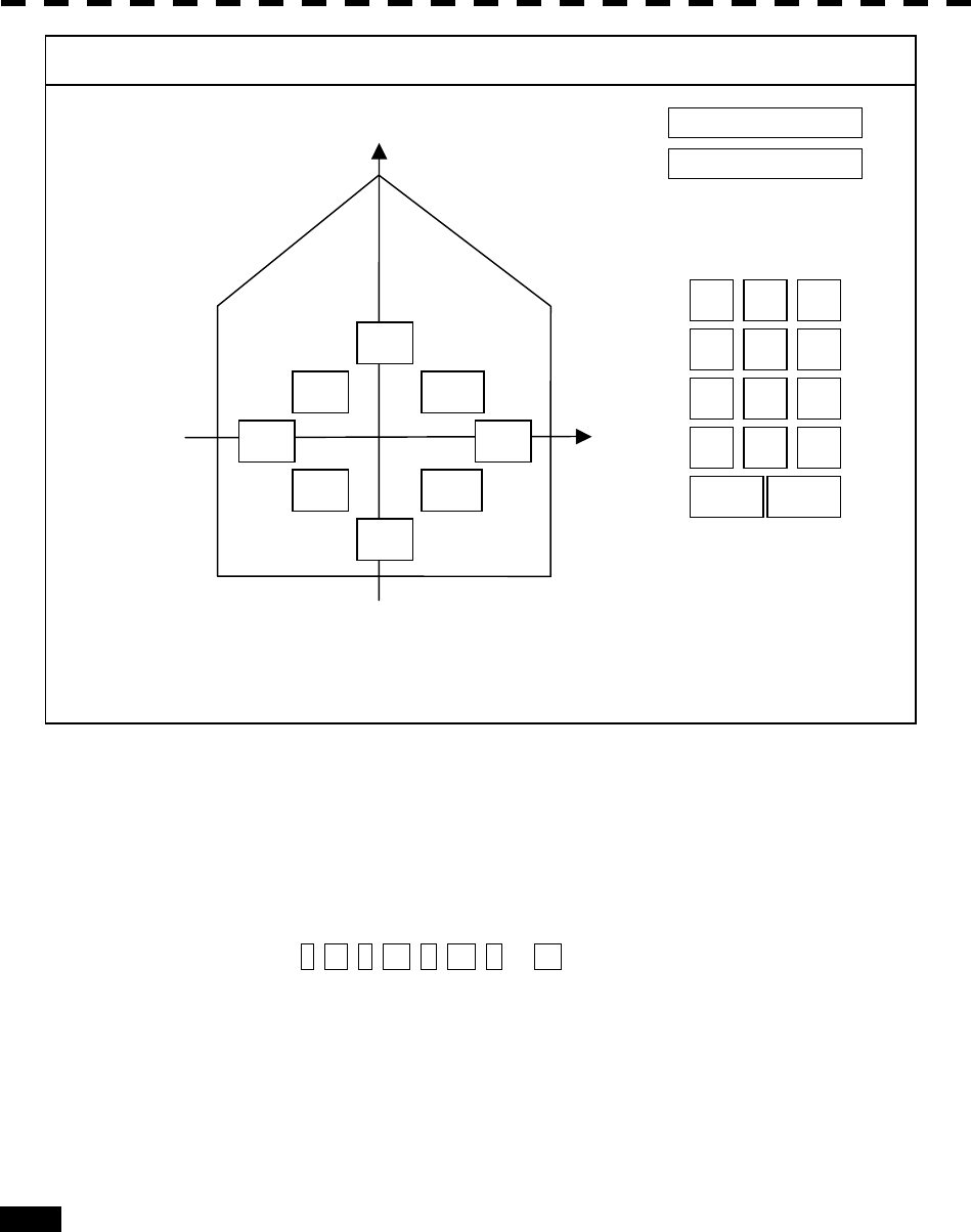
8─45
5 Enter two values, a and b.
With a > 0, GPS antenna is installed in the ship’s heading direction.
With a < 0, GPS antenna is installed in the ship’s stem direction.
With b > 0, GPS antenna is installed in the ship’s starboard side direction.
With b < 0, GPS antenna is to be installed in the ship’s port side direction.
Pressing T, LT, L, LB, B, RB, R, or RT in the own ship gives ±sign, appropriate to the
place, to values a and b.
Press CLR for cancellation. Press ENT to determine the value.
6 Press [0] key.
Entry will end.
Exit 1 Press [RADAR MENU] key.
The Main Menu will reappear.
b
aa: 35m
b: -5m
4 5 6
1 2 3
7 8 9
- 0
+
CL
R
ENT
(-500 to 500 [m])
A
ntenna Location
1. SET
0. EXIT
Set Location Rou
g
hly
T
LT
L
LB
B
RT
R
RB
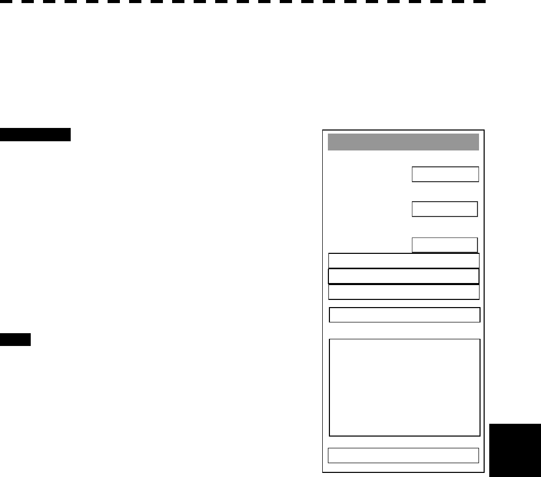
8─46
8.5 Adjustments
8
Sector Blank
1. Sector 1
ON
2. Sector2
ON
ON
0. EXIT
3. Sector3
4. Make Sector 1
5. Make Sector 2
6. Make Sector 3
7. ENT
Sector Blank Function (Sector Blank)
Set a sector range, preventing displaying the radar echo only within the area. Three types of sector can be
created.
[I] Turning ON/OFF the Sector function (Sector 1, 2 and 3)
Procedures 1 Open the Equipment Setup Menu.
2 Press [7] key.
The Sector Blank Menu will appear.
3 Select the number you want to excuted
sector blank, Pressing the numeric
keys [1] to [3].
Switching between ON and OFF is done each
time the key is pressed.
ON: Execution of sector blank
OFF: Cancel
Exit 1 Press [RADAR MENU] key.
The Main Menu will reappear.
Note: This function can be performed only when the scanner
is connected to NKE-2252 and 1075A.
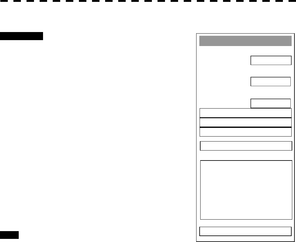
8─47
Sector Blank
1. Sector 1
ON
2. Sector2
ON
ON
0. EXIT
3. Sector3
4. Make Sector 1
5. Make Sector 2
6. Make Sector 3
7. ENT
[II] Making Sector Function (Make Sector 1, 2, 3)
Procedures 1 Open the Equipment Setup Menu.
2 Press [7] key.
The Sector Blank Menu will appear.
3 Slect the number you want to make
sector blank, pressing the numeric
keys [4] to [6].
The sector blank for the numeric key pressed
will be made.
4 Set the start point of the sector blank
by operating the [EBL] dial, and then
press ENT.
The start angle of the sector blank will be set.
5 Set the end point of the sector blank
by operating the [EBL] dial, and then
press ENT.
The end angle of the sector blank will be set.
Exit 1 Press [RADAR MENU] key.
The Main Menu will reappear.
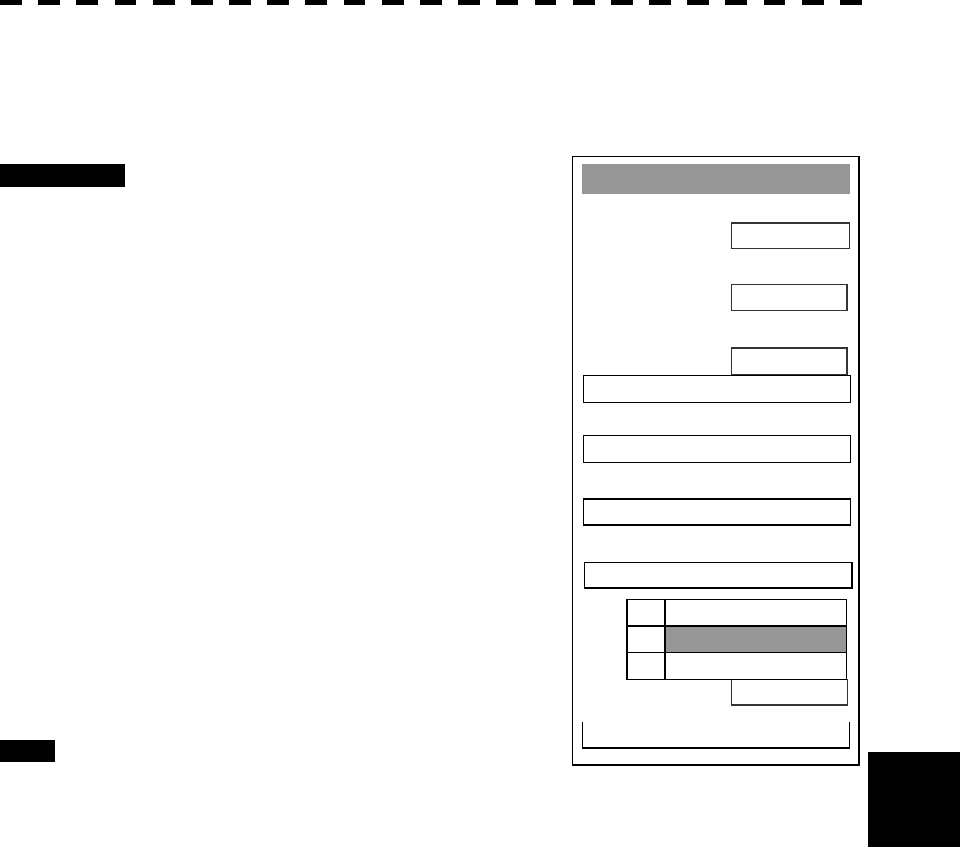
8─48
8.5 Adjustments
8
Baud Rate
1. Bearin
g
Ad
j
ustment
0.0°
2. Ran
g
e Ad
j
ustment
503
32
0. EXIT
3. Tune Ad
j
ustment
4. TRX Settin
g
>
5. COM Port Settin
g
>
ENGLISH
6. Nav Settin
g
>
7. Sector Blank >
9. Lan
g
ua
g
e
1. ENGLISH
2. JAPANESE
3. OTHE
R
Language Setting (Language)
You can switch between Japanese and English.
Procedures 1 Open the Equipment Setup Menu.
2 Press [9].
The Language Selection window will appear.
3 Select the language you want to
display, pressing the numeric keys [1]
to [3].
1. English
2. Japanese
3. Other
“Other” in 3. is a language
corresponding to characters created in
overseas agents.
To confirm whether or not your language is
supported, contact overseas agents or our sales
department.
To make the set language effective, turn off the
power supply and then restart.
Exit 1 Press [RADAR MENU] key.
The Main Menu will reappear.
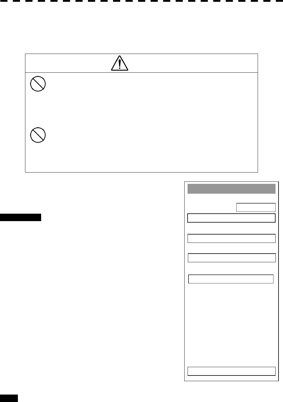
8─49
Maintenance Menu
1. Safety Switch
STANDBY
2. Partial Master Reset
0. EXIT
3. All Master Reset
4. Internal To Card2
5. Card2 To Internal
Maintenance Menu
This item is provided for equipment maintenance, including settings of antenna safety switch, master reset, etc.
CAUTION
Only our service engineers are to make the
adjustment. Neglecting this caution may cause
accidents and failures.
Do not make the adjustments during navigation.
Otherwise, adjustments may affect the radar
functions, causing accidents and failures.
[1] Scanner Safety Switch Setting (Safety Switch)
Procedures 1 Open the Adjust Menu.
2 Press [2] key.
The Maintenance Menu will appear.
3 Press [1] key.
Setting items for the scanner safety switch will
appear.
4 Select the item you want to set,
pressing the numeric key [1] to [4].
1. TX OFF: Stops transmission. (The screen
remains in the transmission status.)
2. STANDBY: Stops transmission. (The
screen switches to the standby status)
3. TX-ON: Continues transmission without
changes. (However, errors in bearing
signals etc. are to occur due to safety
switch-off.)
4. IGNORE ERROR: Continues transmission
without changes.(Errors in bearing signals
etc. due to safety switch-off are also ignored.)
Exit 1 Press [RADAR MENU] key.
The Main Menu will reappear.
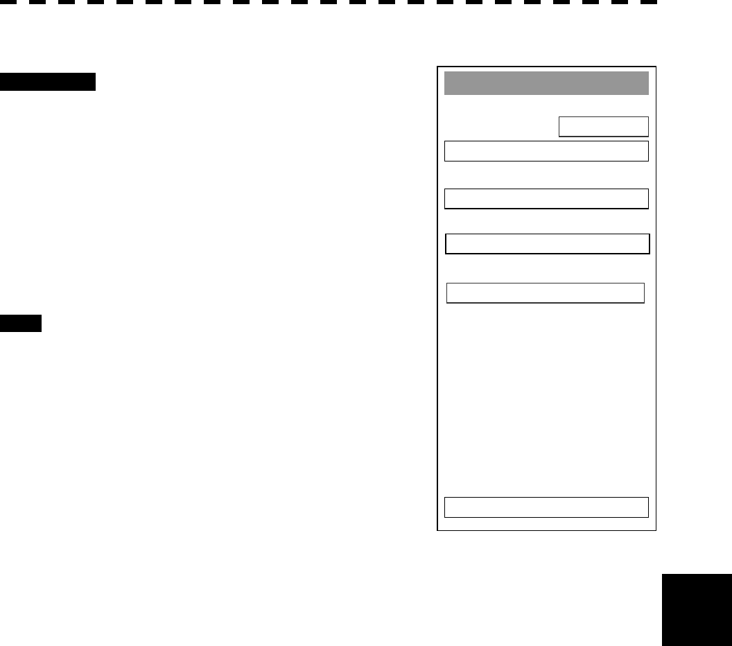
8─50
8.5 Adjustments
8
Maintenance Menu
1. Safety Switch
STANDBY
2. Partial Master Reset
0. EXIT
3. All Master Reset
4. Internal To Card2
5. Card2 To Internal
[II] Partial Master Reset
Procedures 1 Open the Maintenance Menu.
2 Press [2] key.
The Partial Master Reset Execution Check
window will appear.
1 YES: Execution of Partial Master Reset
2 NO: Cancellation
Partial Master Reset resets items except for
those set in the initialization menu.
Exit 1 Press [RADAR MENU] key.
The Main Menu will reappear.

8─51
Maintenance Menu
1. Safety Switch
STANDBY
2. Partial Master Reset
0. EXIT
3. All Master Reset
4. Internal To Card2
5. Card2 To Internal
[III] All Master Reset (All Master Reset)
Procedures 1 Open the Maintenance Menu.
2 Press [3] key.
The All Master Reset Execution Check window
will appear.
1 YES: Execution of All Master Reset
2 NO: Cancellation
All Master Reset resets all items.
Exit 1 Press [RADAR MENU] key.
The Main Menu will reappear.
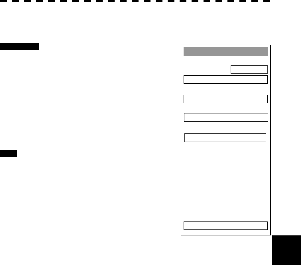
8─52
8.5 Adjustments
8
Maintenance Menu
1. Safety Switch
STANDBY
2. Partial Master Reset
0. EXIT
3. All Master Reset
4. Internal To Card2
5. Card2 To Internal
[IV] Copy Internal Settings to Card2 (Internal To Card2)
Execution of this item requires a memory flash card (option).
Procedures 1 Insert a flash memory card into the
CARD slot 2.
2 Open the Maintenance Menu.
3 Press [4] key.
The execution check window will open to check
whether or not you want to copy the internal
settings to Card2.
1 YES: Execution of copy
2 NO: Cancellation
Exit 1 Press [RADAR MENU] key.
The Main Menu will reappear.
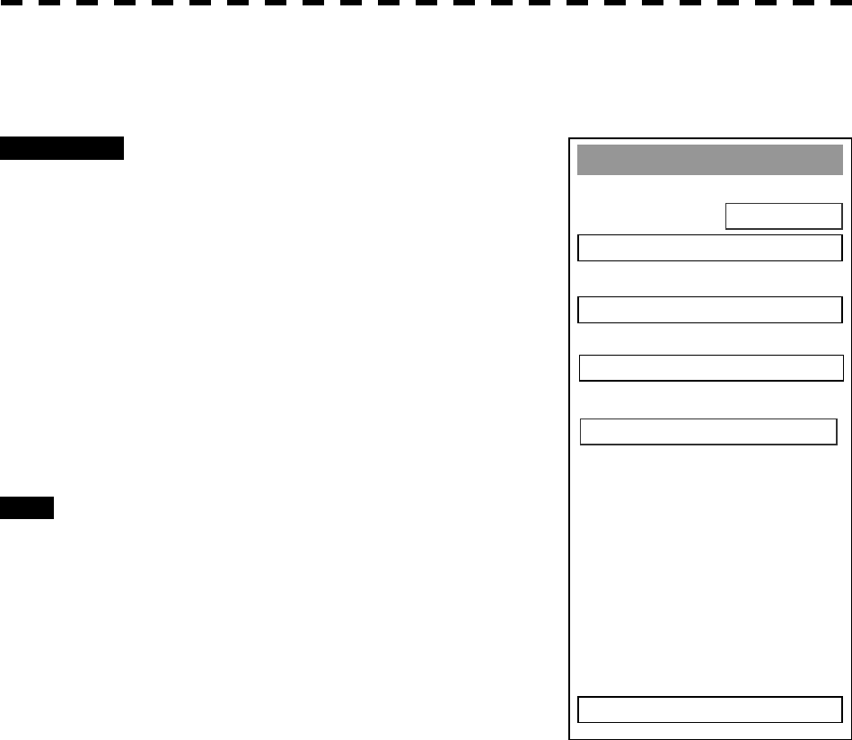
8─53
Maintenance Menu
1. Safety Switch
STANDBY
2. Partial Master Reset
0. EXIT
3. All Master Reset
4. Internal To Card2
5. Card2 To Internal
[V] Read internal settings from Card2.
Execution of this item requires a memory flash card (option).
Procedures 1 Insert the memory flash card, in which
internal settings have been saved, into
Card slot 2.
2 Open the Maintenance Menu.
3 Press [5] key.
The execution check window will open to check
whether or not you want to read the internal
settings from Card2.
1 YES: Read
2 NO: Cancellation
Exit 1 Press [RADAR MENU] key.
The Main Menu will reappear.

8─54
8.5 Adjustments
8
Noise Level
1. Main
140
0. EXIT
2. Settin
g
Mode
OFF
Noise Level Setting (Noise Level)
[1] Setting the noise level for signal processing (Main)
Procedures 1 When the Adjust Menu appears, press
[9] key.
The SP/ATA INIT Setup Menu will appear.
2 Press [1] key.
The Noise Level Menu will appear.
3 Press [1] key.
The Code Input Menu will open to change the
noise level value.
4 Change the value to display echo
correctly.
In addition to the entry on the Code Input menu,
the Multi-functional Dial Control is available to
change the value.
Exit 1 Press [RADAR MENU] key.
The Main Menu will reappear.

8─55
[II] Noise Level Adjustment Mode (Setting Mode)
Procedures 1 When the Adjust Menu appears, press
[9] key.
The SP/ATA INIT Setup Menu will appear.
2 Press [1] key.
Options for Setting Mode will appear.
3 Press [3] key.
Switching between Setting Mode ON and OFF
is done each time the key is pressed.
Exit 1 Press [RADAR MENU] key.
The Main Menu will reappear.
Noise Level
1. Main
140
0. EXIT
2. Settin
g
Mode
OFF
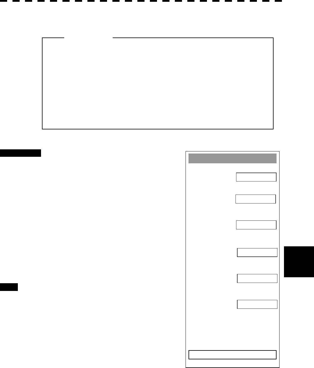
8─56
8.5 Adjustments
8
A
T
A
1. Vector Const
5
2. Video TD Level
15
8
0. EXIT
3. Video Hi
g
h Level
1
4. Video Low Level
NARROW
5. Gate Size
OFF
6. Limit Rin
g
Vector Constant
Procedures 1 Press [9] key while the Adjust Menu is
open.
The SP/ATA INIT Setup Menu will appear.
2 Press [2] key.
The ATA Menu will appear.
3 Press [1] key.
The window for setting vector constants will
appear.
4 Select the value you want to set,
pressing the numeric keys [1] to [8].
Exit 1 Press [RADAR MENU] key.
The Main Menu will reappear.
l Do not change the set value carelessly.
The vector constant shall be set to 5 normally. If the
vector constant value is higher, a target’s vector will
be better followed up when the target and own ship
change their course or speed, but the vector
accuracy will be lower on the contrary.
Attention
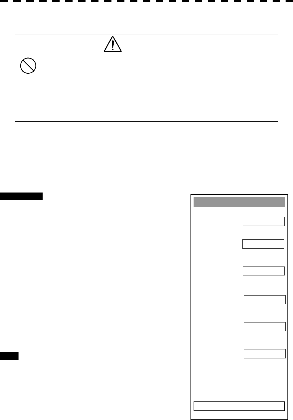
8─57
A
T
A
1. Vector Const
5
2. Video TD Level
15
8
0. EXIT
3. Video Hi
g
h Level
1
4. Video Low Level
NARROW
5. Gate Size
OFF
6. Limit Rin
g
Video TD Level
CAUTION
Do not change the set quantization level carelessly. If
the level deviates from the proper value, the ARPA
acquisition and tracking functions will deteriorate.
Otherwise, this may cause accidents.
The quantization level determines the minimum signal level of the input video to the ARPA target detection
circuit. In this test, the value of the quantization level can be set in a range of 1 to 63.
If the value is set to a lower level, weak target echoes will be inputted to the ARPA target detection circuit, but
much radar noise will also be inputted to the circuit together, and target acquisition and tracking may be
disabled. Therefore, it is important to set a value that is 4 or 5 higher than the detected noise level.
Procedures 1 Press [9] key while the Adjust Menu is
open.
The SP/ATA INIT Setup Menu will appear.
2 Press [2] key.
The ATA Menu will appear.
3 Press [2] key.
The Code Input Menu will appear.
4 Enter the Video TD Level value.
The multi-function control can also be used to
enter the value.
After having entered the value, press ENT.
Exit 1 Press [RADAR MENU] key.
The Main Menu will reappear.
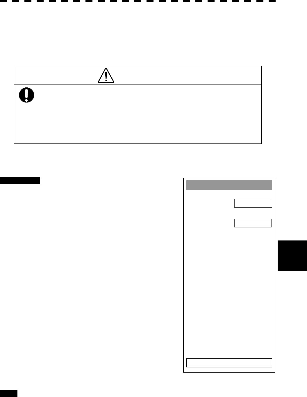
8─58
8.5 Adjustments
8
MBS
1. MBS Level
0
2. MBS Area
0
0. EXIT
Main Bang Suppression Level Adjustment (MBS Level)
Main Bang Suppression is adjusted to suppress main bang, a reflection signal from 3D circuit including wave
guide tube, that generally appears as a circular image focusing on the center of the radar display. Optimum
adjustment allows main bang image to remain lightly on the display.
CAUTION
Do not change this adjusted level carelessly.
Incorrect adjustment may erase targets in point-blank
range and cause collision, resulting in death or serious
injury.
This adjustment is made for settings in the processing circuit of the display unit.
Procedures 1 Perform the following operation before
setting.
· Set the range to 0.125 nm.
· Set the radar video enhance function.
· Set the correlation processing function to
OFF.
· Rotate the [AUTO-SEA] control to achieve
the strength with which main bang can be
judged.
· Rotate [AUTO-RAIN] control to the
minimum position (counterclockwise fully).
· Rotate [GAIN/PL] control to the maximum
position (clockwise fully).
2 Display the SP/ATA INIT Setup Menu.
3 Press [3] key.
The MBS Menu will appear.
4 Press [1] key.
The Code Input Menu will appear.
5 Enter the Main Bung Suppression
Level value.
Adjust the value to erase the main bang.
Exit 1 Press [RADAR MENU] key.
The Main Menu will reappear.
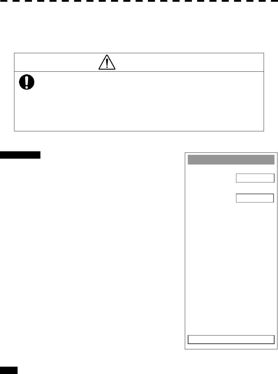
8─59
MBS
1. MBS Level
0
2. MBS Area
0
0. EXIT
Main Bang Suppression Area Adjustment (MBS Area)
Adjust the main bang suppression area.
CAUTION
Do not change this adjusted level carelessly.
Incorrect adjustment may erase targets in point-blank
range and cause collision, resulting in death or serious
injury.
Procedures 1 Perform the following operation before
setting.
· Set the range to 0.125 nm.
· Set the radar video enhance function.
· Set the correlation processing function to
OFF.
· Rotate the [AUTO-SEA] control to achieve
the strength with which main bang can be
judged.
· Rotate [AUTO-RAIN] control to the
minimum position (counterclockwise fully).
· Rotate [GAIN/PL] control to the maximum
position (clockwise fully).
2 Display the SP/ATA INIT Setup Menu.
3 Press [3] key.
The MBS Menu will appear.
4 Press [1] key.
The Code Input Menu will appear.
5 Enter the Main Bung Suppression
Level value.
Adjust the value to erase the main bang.
Exit 1 Press [RADAR MENU] key.
The Main Menu will reappear.

8─60
8.5 Adjustments
8
Adjustment of NSK Unit to GYRO Compass and Log
The NSK Unit of the radar equipment is designed to be compatible with almost all types of gyro compass by
switch operation (For the step motor type, 24 VDC to 100 VDC, and for the synchro-motor type, the primary
excitation voltage is 50 VAC to 115 VAC).
Before power-on operation, the switches S1, S2, S5 and jumper JP1 on the NSK Unit (PC4201) shall be set to
the type of gyro compass in use in accordance with the procedures as described below. The gyro select switch
on the NSK Unit is set to the gyration ratio of 360X and to be compatible with the synchro type before delivery
from factory.
Check the type of the gyro compass used in own ship and make settings in the procedures below.
(1) Set the switches of the NSK Unit (PC4201) before turning on the radar equipment.
· S1: Set it to [OFF].
· S2: There are two types of gyro compasses: a compass of one type outputs a step signal, and the other
outputs a synchro signal. Make sure of the type of gyro compass used with the own ship before
setting S2.
[SYNC] .......................................Synchro signal
[STEP].........................................Step signal
· S5: Set S5 depending on the type of the gyro compass currently in use, according to the S5 setting
table.
S5-1: ..................................Set this switch assembly according to the particular type of gyro.
[OFF]...........................................Synchro signal
[ON] ............................................Step signal
S5-2, -3................................Gyration ratio
360X 180X 90X 36X
S5-2 OFF OFF ON ON
S5-3 OFF ON OFF ON
S5-4.....................................Gyration direction
[OFF]...........................................Normal (clockwise)
[ON] ............................................Reverse (counterclockwise)
S5-5.....................................Log type-1
[OFF]...........................................Pulse signal
[ON] ............................................Synchro signal
S5-6.....................................Not used
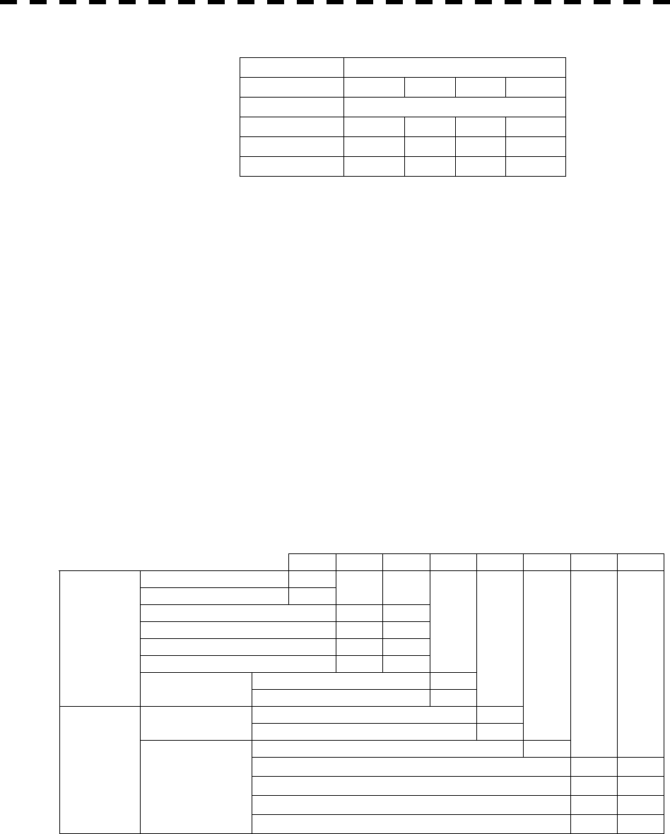
8─61
S5-7, -8............................... Log ratio
Pulse/NM (pulse signal)
800 400 200 100
Gyration/NM (synchro signal)
360X 180X 90X 36X
S5-7 OFF OFF ON ON
S5-8 OFF ON OFF ON
· S6:Log test. Set it to [NORMAL].
· S7: Normal or BSH(IMO) specifications selection. Set it to [NORMAL].
· Set JP1 according to the particular gyro.
[SYNC]....................................... Synchro signal
[STEP] ........................................ Step signal
(2) Connect the gyro signal and the log signal cables to the NSK Circuit. (PC4201)
(3) Set S1 to [ON].
* After power-on operation, the switch S5-4 shall be set to [ON] if the radar video and the indicated value of
COURSE (own ship’s true bearing) is reversed.
Table 8-17 Gyro and Log Select Switches (S5 Dip Switch)
S5 Setting Table
1 2 3 4 5 6 7 8
SYNC 0
STEP 1
360X 0 0
180X 0 1
90X 1 0
36X 1 1
Normal (NOR) 0
GYRO SIG.
DIRECTION Reverse (REV) 1
PULSE 0
TYPE SYNCHRO 1
0
800P/360X 0 0
400P/180X 0 1
200P/90X 1 0
LOG SIG.
PULSE/NM
100P/30X 1 1
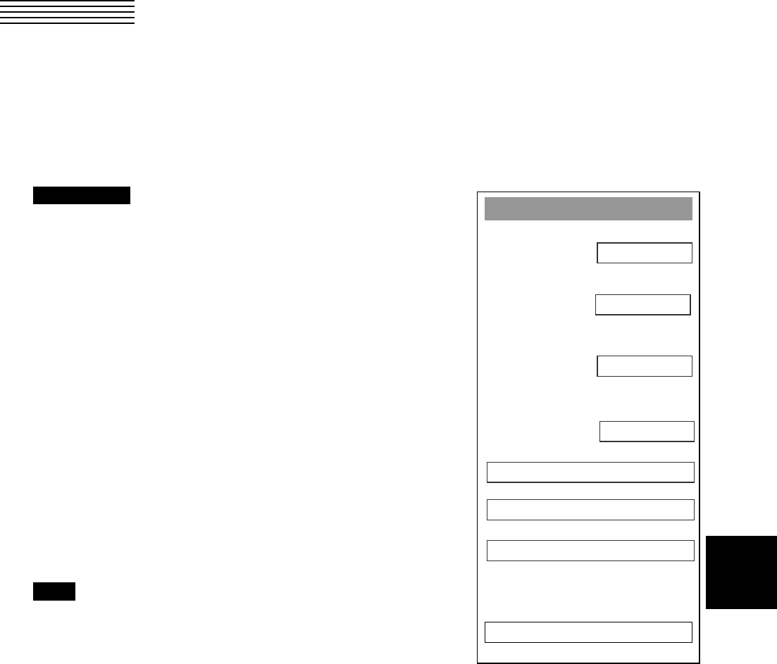
8─62
8
8.6 SETTING
True Bearing Setting (Set GYRO)
Adjust the bearing that the bearing angle of the radar is the same as that of the gyro.
Procedures 1 Press [RADAR MENU] key twice.
The Main Menu will appear.
2 Press [7] key.
The NAV Equipment Setting Menu will appear.
3 Press [1] key.
The Code Input Menu will appear.
4 Adjust true bearing value.
Adjust the bearing that the bearing angle of the
radar is the same as that of the gyro.
The multi-function control can also be used to
enter the value.
After having entered the value, press ENT.
Exit 1 Press [RADAR MENU] key.
The menu will be closed.
NAV Equipment Settin
g
1. Set GYRO
0.0°
2. Headin
g
Equipment
GYRO
MAN
0. EXIT
3. Speed Equipment
0.0kts
4. Manual Speed
5. MAG Compass Settin
g
6. Set/Drift Settin
g
7. GPS Settin
g
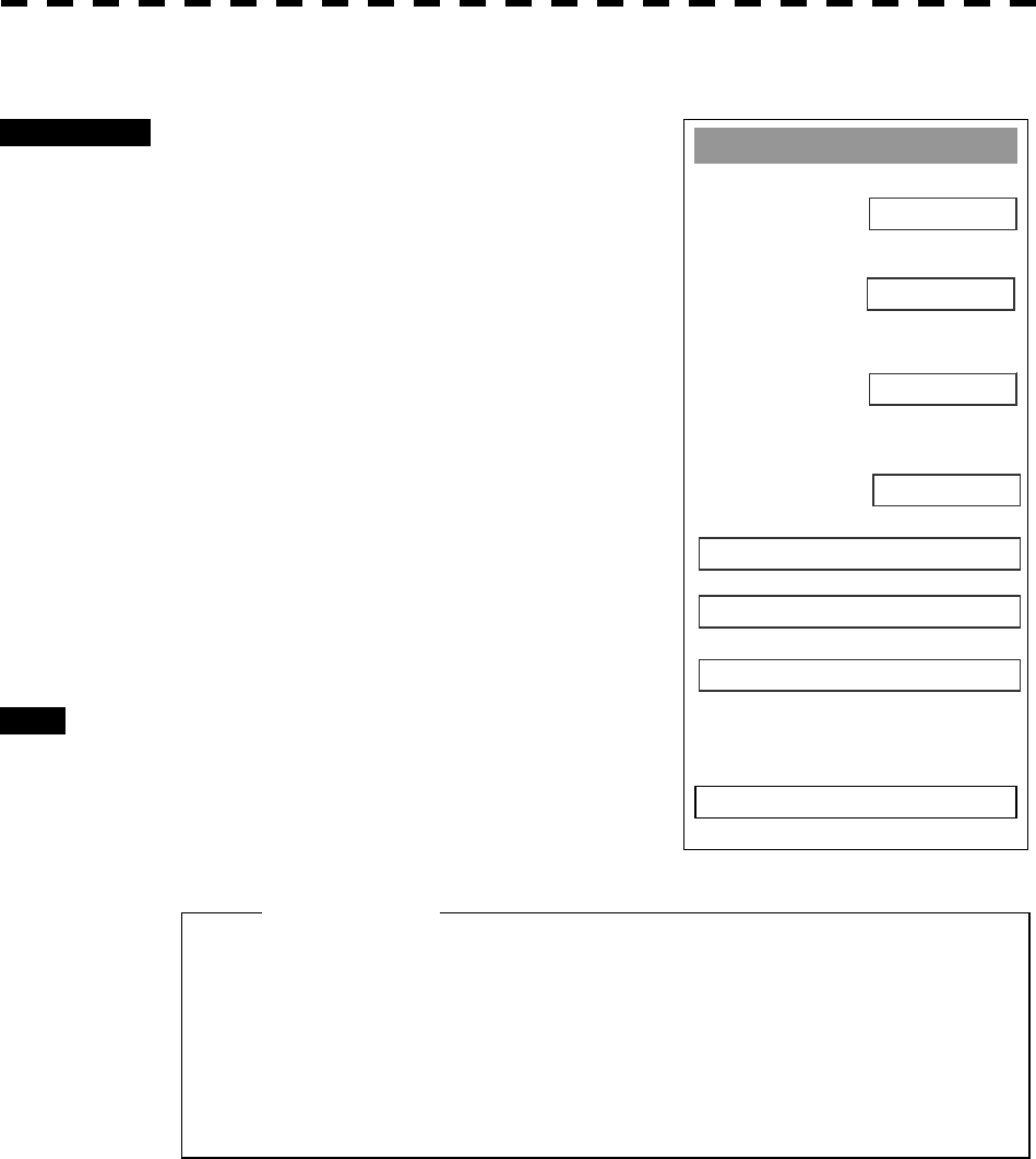
8─63
NAV Equipment Settin
g
1. Set GYRO
0.0°
2. Headin
g
Equipment
GYRO
MAN
0. EXIT
3. Speed Equipment
0.0kts
4. Manual Speed
5. MAG Compass Settin
g
6. Set/Drift Settin
g
7. GPS Settin
g
Ship Speed Equipment Setting (Speed Equipment)
Procedures 1 Press [RADAR MENU] key twice.
The RADAR Menu will appear.
2 Press [7] key.
The NAV Equipment Setting Menu will appear.
3 Press [3] key.
4 Select a ship speed sensor from the
pull-down menu.
Types of selectable speed sensors:
1: Manual
2: Log
3: 2-axis log (NMEA signal: Speed over water)
4: 2-axis log (NMEA signal: Speed over
ground)
Exit 1 Press [RADAR MENU] key.
The menu will be closed.
l The manually entered speed is effective only when
“MANUAL” is set.
l 2-axis log cannot be effective when the sentence
VBW of NMEA0183 is not entered.
Attention

8─64
8
8.6 Setting
NAV Equipment Settin
g
1. Set GYRO
0.0°
2. Headin
g
Equipment
GYRO
MAN
0. EXIT
3. Speed Equipment
0.0kts
4. Manual Speed
5. MAG Compass Settin
g
6. Set/Drift Settin
g
7. GPS Settin
g
Manual Speed Setting (Manual Speed)
Procedures 1 Press [RADAR MENU] key twice.
2 Press [7] key.
NAV Equipment Setting Menu will appear.
3 Press [4] key.
The Code Input menu will appear.
4 Pressing a numeric key, enter the
value and select “ENT.”
The multi-function control is also available for
the entry.
Note: The manually entered speed is effective only when
“MANUAL” is set.
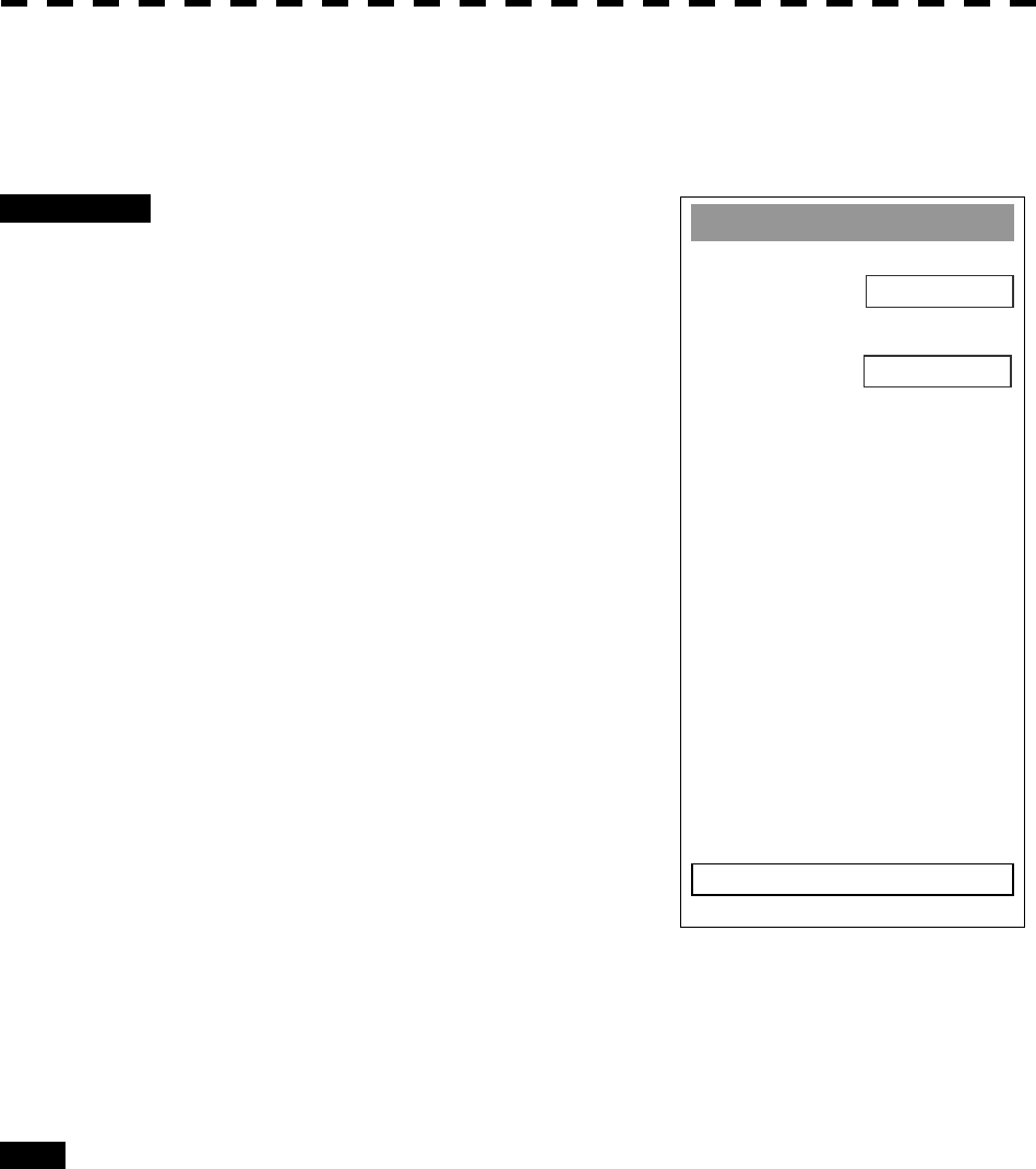
8─65
MAG Compass Settin
g
1. Headin
g
Correction
OFF
2. Correct Value
0.0°E
0. EXIT
MAG Compass Setting
Set the MAG compass.
Procedures 1 Press [RADAR MENU] key twice.
The Radar Menu will appear.
2 Press [7] key.
NAV Equipment Setting Menu will appear.
3 Press [5] key.
MAG Compass Setting Menu will appear.
4 Press [1] key.
This item is set as to whether or not the
heading bearing is to be corrected. Switching
between ON and OFF is done each time you
press [1] key.
5 Press [2] key.
The Code Input Menu will appear.
6 Pressing a numeric key, enter the
value. Select “ENT” and then
determine the value.
The correction direction and angle will be set.
On the screen, press “+” to make correction in
the eastern direction, and press “-” to make correction in the western direction. Also
enter a correction angle, pressing the numeric key.
The multi-function control is also available for the entry. To do so, enter the correction
direction, press the multi-function control, enter the correction angle, and then set ENT in
order.
Exit 1 Press [RADAR MENU] key.
The menu will be closed.
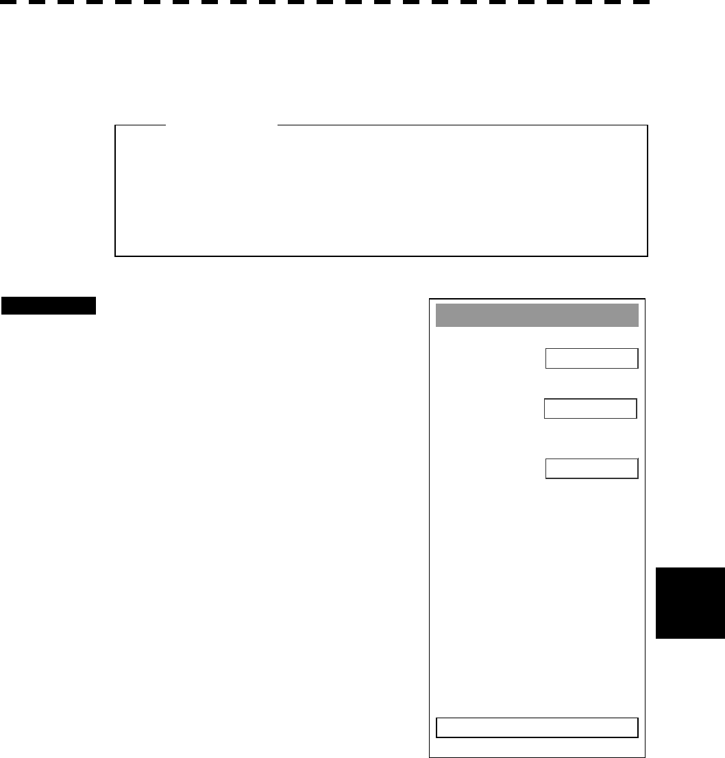
8─66
8
8.6 Setting
Set/Drift Settin
g
1. Correction
OFF
2. Set
0.0°
0.0kts
0. EXIT
3. Drift
Current Correction (SET/DRIFT) Setting
The current set and drift will be set.
Procedures 1 Press [RADAR MENU] key twice.
The RADAR Menu will appear.
2 Press [7] key.
The NAV Equipment Setting Menu will appear.
3 Press [6] key.
The Set/Drift Setting Menu will appear.
4 Press [1] key to enable Correction.
The setting of Correction is switched back and
forth between ON and OFF each time [1] key is
pressed.
5 Press [2] key.
The Code Input Menu will appear.
6 Enter the direction of tendency.
The direction of tendency will be set. The
multi-function control is also available for the
entry.
After having entered the direction, press ENT.
l The manually entered speed is effective only when 1.
MANUAL or 2. 1AXIS is set in 2. SELECT SPEED of
SETTING1 Menu.
Attention

8─67
7 Press [3] key.
The Code Input Menu will appear.
8 Enter the speed of tendency.
The speed of tendency will be set. The multi-function control is also available for the
entry.
After having enter the value, press ENT.
Exit 1 Press [RADAR MENU] key.
The menu will be closed.
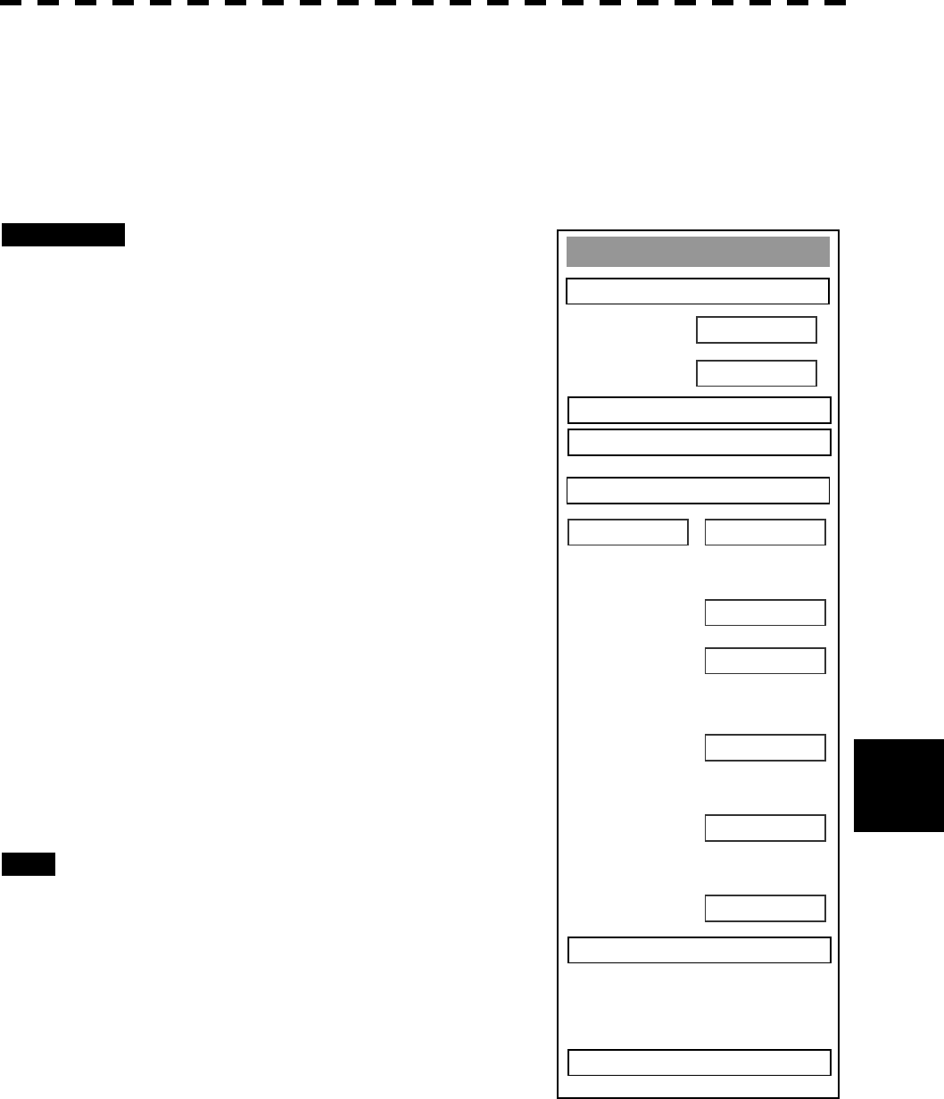
8─68
8
8.6 Setting
GPS Process Settin
g
1. Position
00
’
00.000
000
’
00.000
0. EXIT
00
3. Geodetic
N
E
2. Exclution
00 00 00 00 00 00
WGS-84
4. Antenna Hei
g
ht
0m
5. Fix Mode 2D
6. DOP Level
Up to 5
7. Position Avera
g
e
LONG
8. Master Reset
OFF
9. Send Data
Setting in GPS Receiver (GPS Process Setting)
Set an initial value in the GPS receiver (our GPS receiver).
[I] Own ship position setting
Procedures 1 Press [RADAR MENU] key twice.
The Radar Menu will appear.
2 Press [7] key.
NAV Equipment Setting Menu will appear.
3 Press [7] key.
GPS Setting Menu will appear.
4 Press [1] key.
GPS Process Setting Menu will appear.
5 Press [1] key.
The Code Input menu will appear.
Enter the latitude, press ENT, enter the
longitude, and then press ENT in order.
The multi-function control is also available to
enter the values.
6 After having entered the values, press
[9] key, and transmit the setting
contents to the GPS receiver.
Exit 1 Press [RADAR MENU] key.
The Main Menu will reappear.
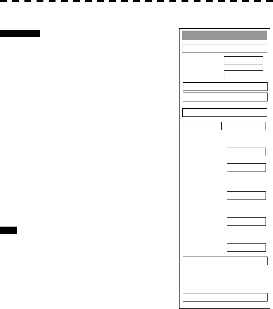
8─69
GPS Process Settin
g
1. Position
00
’
00.000
000
’
00.000
0. EXIT
00
3. Geodetic
N
E
2. Exclution
00 00 00 00 00 00
WGS-84
4. Antenna Hei
g
ht
0m
5. Fix Mode 2D
6. DOP Level
Up to 5
7. Position Avera
g
e
LONG
8. Master Reset
OFF
9. Send Data
[II] Setting of Banned Satellite (Excltion)
Procedures 1 Press [RADAR MENU] key twice.
The Radar Menu will appear.
2 Press [7] key.
NAV Equipment Setting Menu will appear.
3 Press [7] key.
GPS Setting Menu will appear.
4 Press [1] key.
GPS Process Setting Menu will appear.
5 Press [2] key.
The Code Input menu will appear.
Enter the number of the banned satellite.
The multi-function control is also available to
enter the values.
6 After having entered the value, press
[9] key, and transmit the setting
contents to the GPS receiver.
Exit 1 Press [RADAR MENU] key.
The Main Menu will reappear.
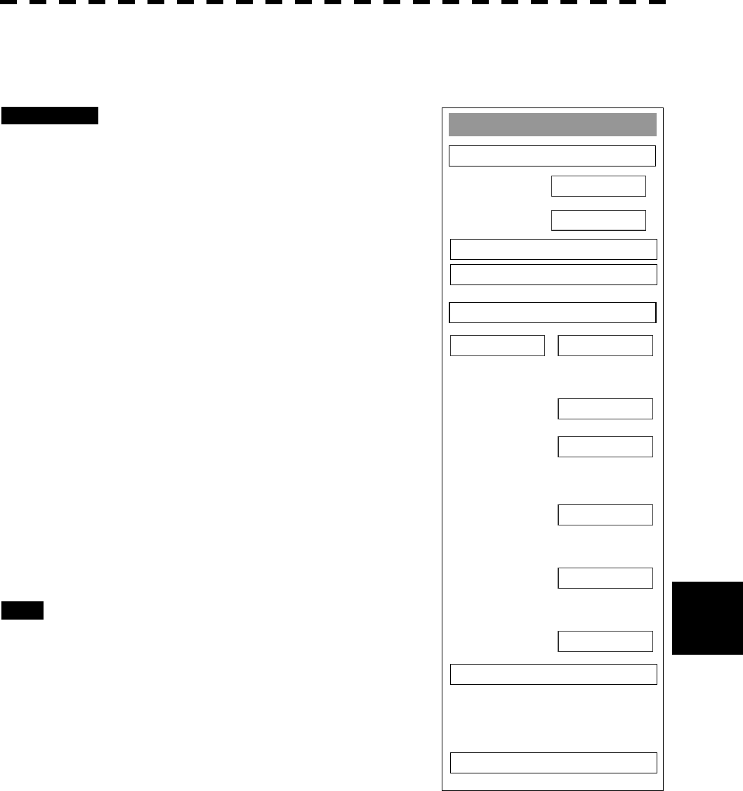
8─70
8
8.6 Setting
GPS Process Settin
g
1. Position
00
’
00.000
000
’
00.000
0. EXIT
00
3. Geodetic
N
E
2. Exclution
00 00 00 00 00 00
WGS-84
4. Antenna Hei
g
ht
0m
5. Fix Mode 2D
6. DOP Level
Up to 5
7. Position Avera
g
e
LONG
8. Master Reset
OFF
9. Send Data
[III] Geodetic System Setting (Geodetic)
Set the geodetic system in which the own ship is currently existent.
Procedures 1 Press [RADAR MENU] key twice.
The Radar Menu will appear.
2 Press [7] key.
NAV Equipment Setting Menu will appear.
3 Press [7] key.
GPS Setting Menu will appear.
4 Press [1] key.
GPS Process Setting Menu will appear.
5 Press [3] key.
The Code Input menu will appear.
Enter the geodetic system in accordance with
the table on the following page.
The multi-function control is also available to
enter the values.
6 After having entered the values, press
[9] key to transmit the setting contents
to the GPS receiver.
Exit 1 Press [RADAR MENU] key.
The Main Menu will reappear.

8─71
List of Geodetic Systems
No. Name
0 WGS-84
1 WGS-72
2 Japan
3 North American 1927(U.S)
4 North American 1927(Canada & Alaska)
5 European 1950 (Europe)
6 Australian geodetic 1966 (Australia)
7 Ordance Survery of Great Britain (England)
8 NAD-83
9 - (No Use)
10 - (No Use)
11 ADINDAN (Etiopia & Sudan)
12 ARC 1950 (Botswana)
13 AUSTRALIAN GEODETIC 1984 (Australia)
14 BERMUDA 1957 (the Bermudas)
15 BOGOTA OBSERVATORY (Columbia)
16 CAMPO INCHAUSPE
17 CHATHAM 1971
18 CHUAASTRO (Paraguay)
19 CORREGO ALEGRE (Brazil)
20 DJAKARTA (VATAVIA) (Sumata)
21 EUROPEAN 1979 (Europe)
22 GEODETIC DATUM 1949 (New Zeland)
23 GUAM 1963 (Guam)
24 HAYFORD 1910 (Finland)
25 HJORSEY 1955 (Ice land)
26 INDIAN (India & Nepal)
27 IRELAND1965 (Ireland)
28 KERTAU 1948 (West Malaysia)
29 L.C.5 ASTRO (Cayman Black Island)
30 LIBERIA 1964 (Liberia)
31 LUZON (Philippines)
32 MERCHICH (Morocco)
33 MINNA (Cameroon)
34 NAHRWAN (Oman)
35 NAPARIMA, BWI (Trinidad & Tobago)
36 OLD EGYPTIAN (Egypt)
37 OLD HAWAIIAN (Hawaii)
38 PCO DE LAS NIEVES (Canary)
39 PROVISIONAL SOUTH AMERICAN 1956 (South America)
40 PROVISIONAL SOUTH CHILEAN 1963 (South Chile)
41 PUERTO RICO (Puerto Rico & Virgin Islands)
42 QORNOQ (South Greenland)
43 RT90 (Sweden)
44 SANTA BRAZ (San Miguel island & Saint Mary islands)
45 SOUTH AMERICAN 1969 (South America)
46 SOUTHWEST BASE (Faial & Sao Jorge & Pico & Graciosa & Terceira island)
47 TIMBALAI 1948 (Brunei & East Malaysia)
49 - (No Use)
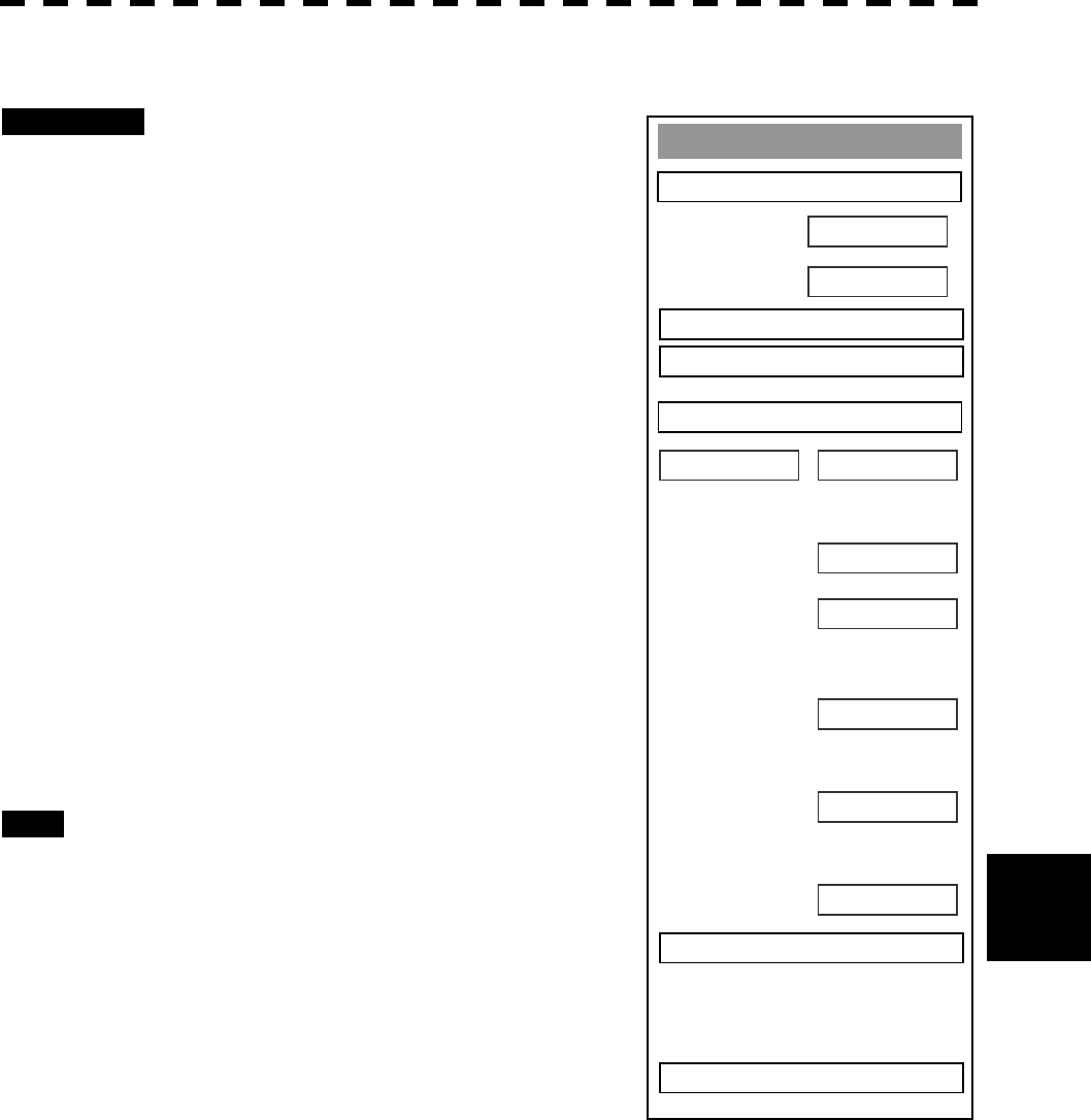
8─72
8
8.6 Setting
GPS Process Settin
g
1. Position
00
’
00.000
000
’
00.000
0. EXIT
00
3. Geodetic
N
E
2. Exclution
00 00 00 00 00 00
WGS-84
4. Antenna Hei
g
ht
0m
5. Fix Mode 2D
6. DOP Level
Up to 5
7. Position Avera
g
e
LONG
8. Master Reset
OFF
9. Send Data
[IV] Antenna Height Setting (Antenna Height)
Procedures 1 Press [RADAR MENU] key twice.
The Radar Menu will appear.
3 Press [7] key.
NAV Equipment Setting Menu will appear.
4 Press [7] key.
GPS Setting Menu will appear.
5 Press [1] key.
GPS Process Setting Menu will appear.
6 Press [4] key.
The Code Input menu will appear.
Enter the antenna height of the own ship.
The multi-function control is also available to
enter the values.
7 After having entered the value, press
[9] key, and transmit the contents of
the settings to the GPS receiver.
Exit 1 Press [RADAR MENU] key.
The Main Menu will reappear.
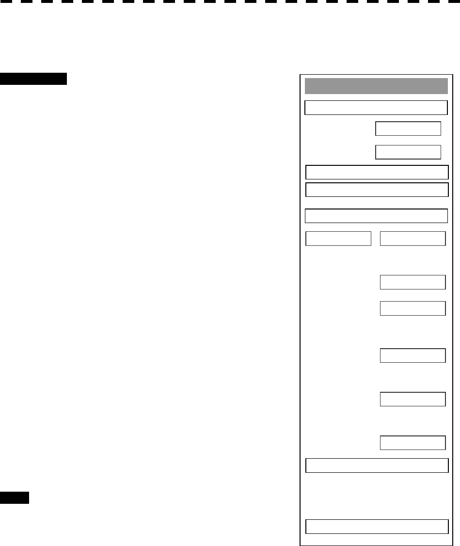
8─73
GPS Process Settin
g
1. Position
00
’
00.000
000
’
00.000
0. EXIT
00
3. Geodetic
N
E
2. Exclution
00 00 00 00 00 00
WGS-84
4. Antenna Hei
g
ht
0m
5. Fix Mode 2D
6. DOP Level
Up to 5
7. Position Avera
g
e
LONG
8. Master Reset
OFF
9. Send Data
[V] Fix Mode Setting (Fix Mode)
Set the GPS fix mode.
Procedures 1 Press [RADAR MENU] key twice.
The Radar Menu will appear.
2 Press [7] key.
NAV Equipment Setting Menu will appear.
3 Press [7] key.
GPS Setting Menu will appear.
4 Press [1] key.
GPS Process Setting Menu will appear.
5 Press [5] key.
From the pull-down menu, you can select the
following modes.
2D: 2D positioning only. Height cannot
be acquired.
3D: 3D positioning can be done with
height acquired.
AUTO: 2D positioning and 3D positioning
can automatically be selected with
optimum.
7 After having entered the values, press
[9] key to transmit the setting
contents to the GPS receiver.
Exit 1 Press [RADAR MENU] key.
The Main Menu will reappear.
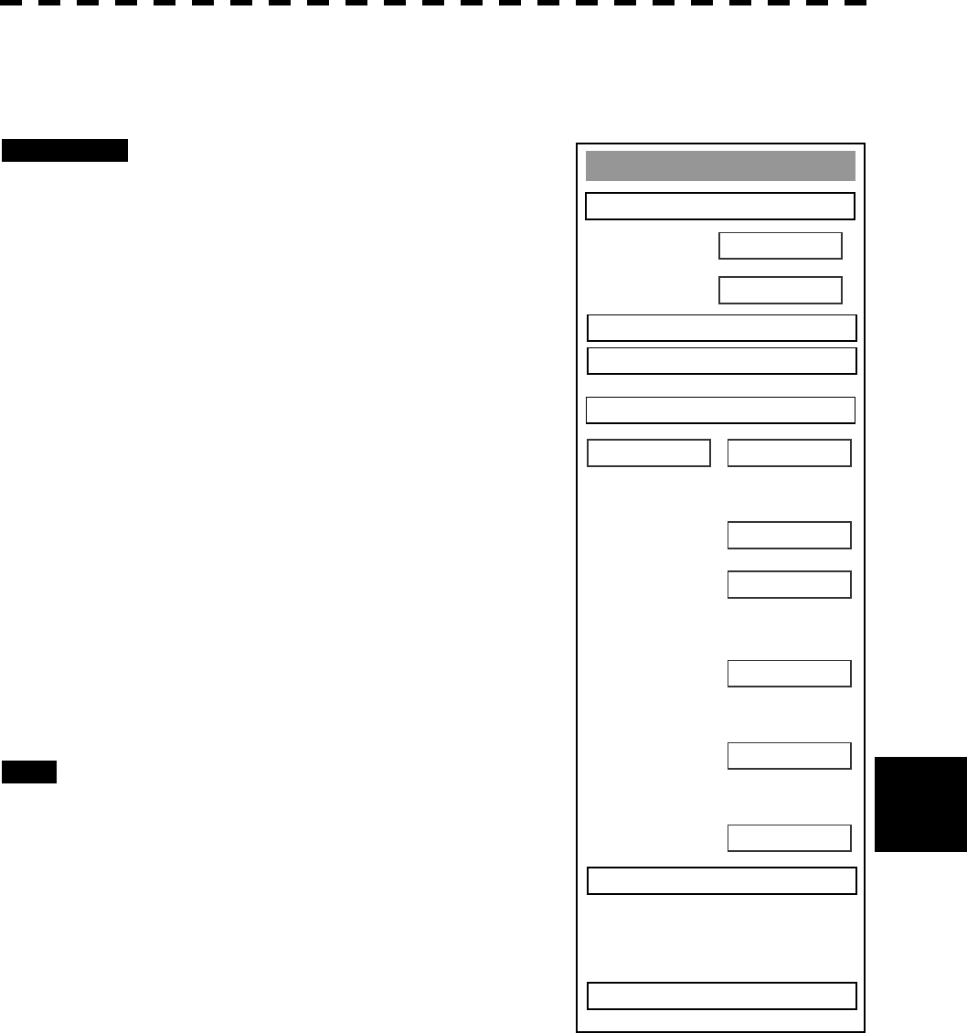
8─74
8
8.6 Setting
GPS Process Settin
g
1. Position
00
’
00.000
000
’
00.000
0. EXIT
00
3. Geodetic
N
E
2. Exclution
00 00 00 00 00 00
WGS-84
4. Antenna Hei
g
ht
0m
5. Fix Mode 2D
6. DOP Level
Up to 5
7. Position Avera
g
e
LONG
8. Master Reset
OFF
9. Send Data
[VI] HDOP Level Setting (DOP Level)
Set the HDOP level of the GPS receiver.
Procedures 1 Press [RADAR MENU] key twice.
The Radar Menu will appear.
2 Press [7] key.
NAV Equipment Setting Menu will appear.
3 Press [7] key.
GPS Setting Menu will appear.
4 Press [1] key.
GPS Process Setting Menu will appear.
5 Press [6] key.
From the pull-down menu, you can select a
desired level. As the value is smaller, the
precision becomes higher, but positioning grows
more difficult.
6 After having entered the values, press
[9] key to transmit the setting contents
to the GPS receiver.
Exit 1 Press [RADAR MENU] key.
The Main Menu will reappear.
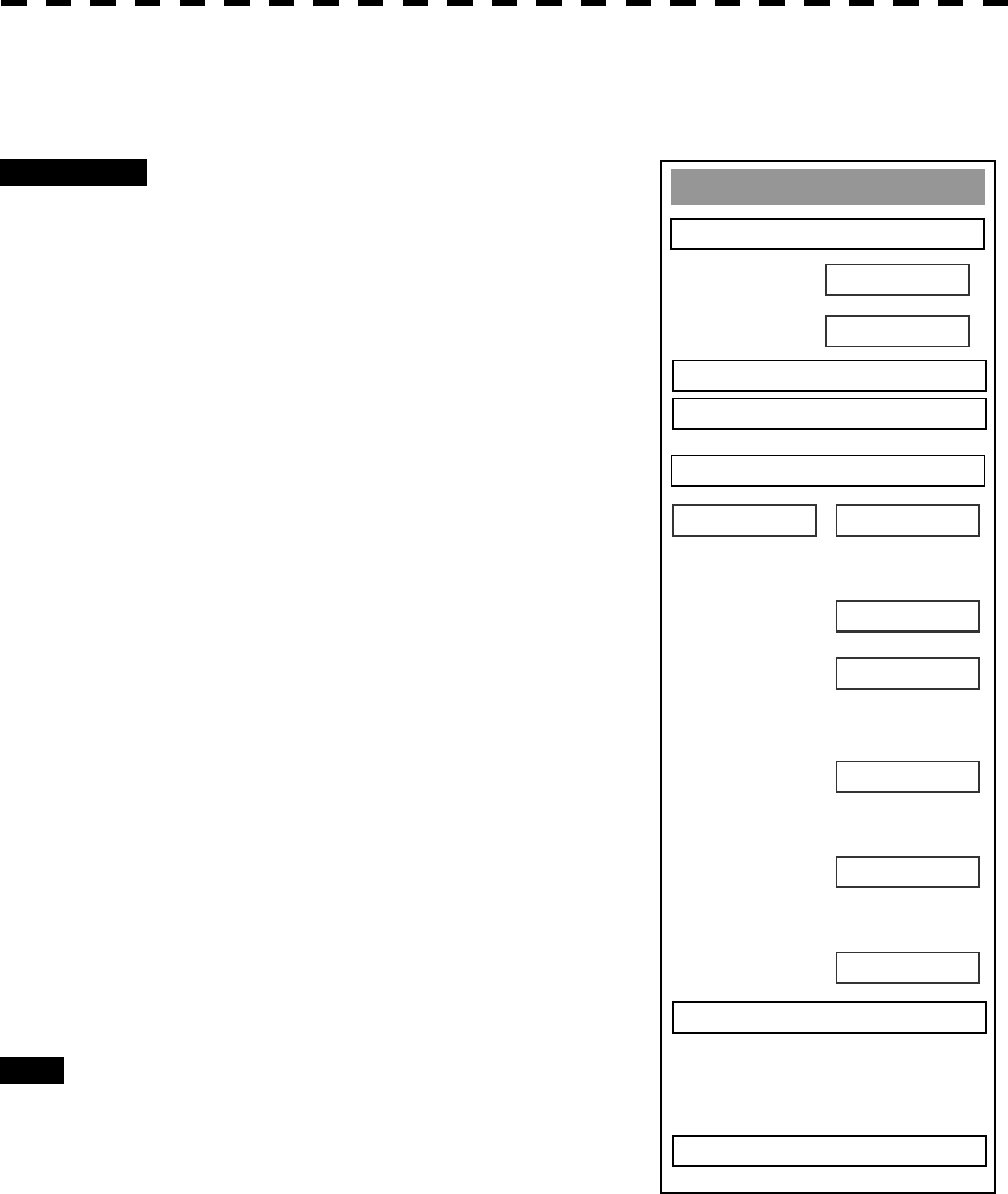
8─75
GPS Process Settin
g
1. Position
00
’
00.000
000
’
00.000
0. EXIT
00
3. Geodetic
N
E
2. Exclution
00 00 00 00 00 00
WGS-84
4. Antenna Hei
g
ht
0m
5. Fix Mode 2D
6. DOP Level
Up to 5
7. Position Avera
g
e
LONG
8. Master Reset
OFF
9. Send Data
[VII] Average Level Setting (Position Average)
Set the time to average position information etc. output from the GPS receiver.
Procedures 1 Press [RADAR MENU] key twice.
The Radar Menu will appear.
2 Press [7] key.
NAV Equipment Setting Menu will appear.
3 Press [7] key.
GPS Setting Menu will appear.
4 Press [1] key.
GPS Process Setting Menu will appear.
5 Press [7] key.
From the pull-down menu, select the
following:
LONG,
STANDARD, and
NONE.
The degree of average becomes small in order
of LONG, STANDARD and NONE. As the
degree of average is smaller, the update speed
of position information is higher but dispersion
is larger.
6 After having entered the values, press
[9] key to transmit the setting
contents to the GPS receiver.
Exit 1 Press [RADAR MENU] key.
The Main Menu will reappear.
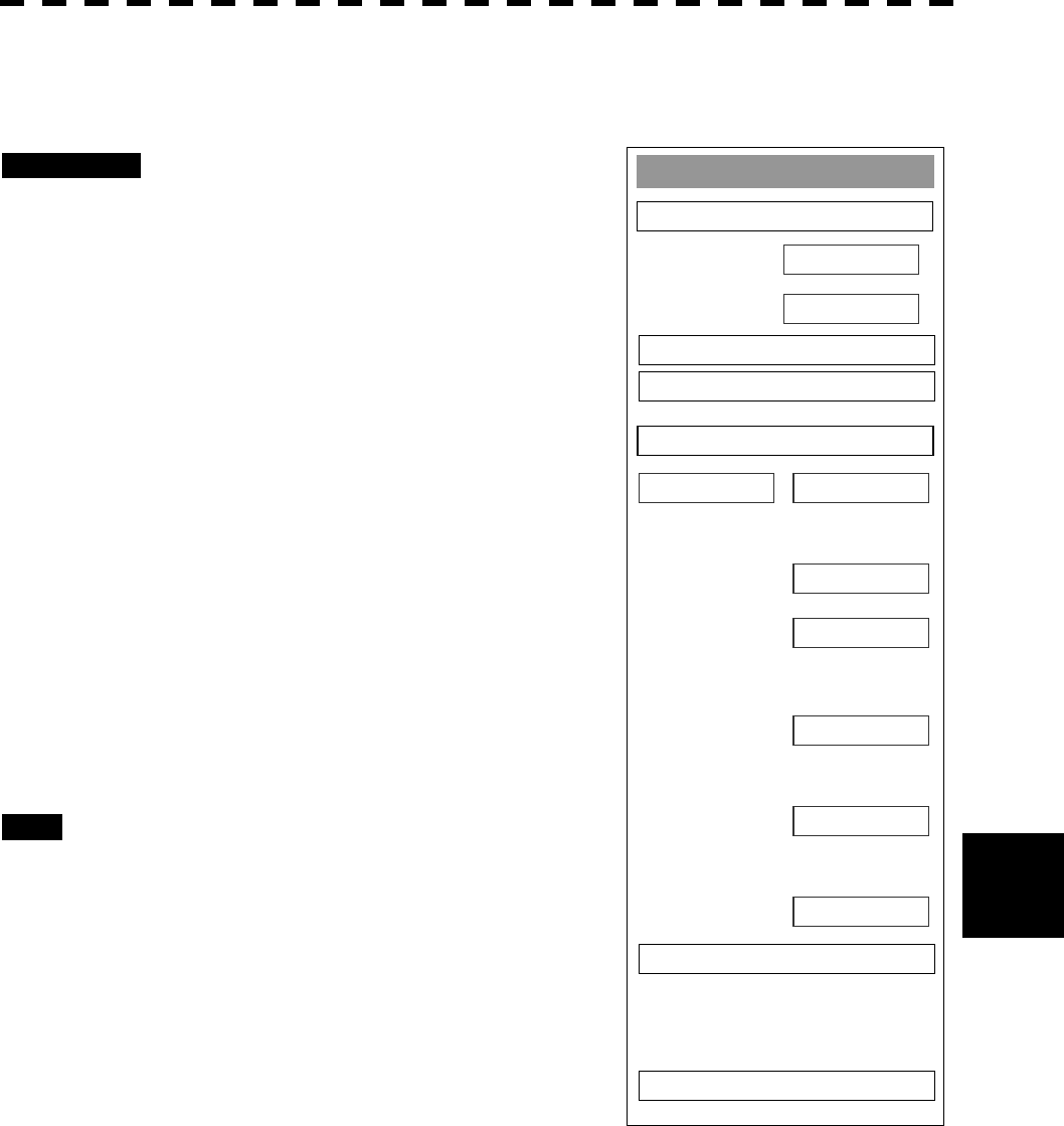
8─76
8
8.6 Setting
GPS Process Settin
g
1. Position
00
’
00.000
000
’
00.000
0. EXIT
00
3. Geodetic
N
E
2. Exclution
00 00 00 00 00 00
WGS-84
4. Antenna Hei
g
ht
0m
5. Fix Mode 2D
6. DOP Level
Up to 5
7. Position Avera
g
e
LONG
8. Master Reset
OFF
9. Send Data
[VII] Master Reset (Master Reset)
Transmit the master reset to the GPS receiver to initialize the GPS receiver.
Procedures 1 Press [RADAR MENU] key twice.
The Radar Menu will appear.
2 Press [7] key.
NAV Equipment Setting Menu will appear.
3 Press [7] key.
GPS Setting Menu will appear.
4 Press [1] key.
GPS Process Setting Menu will appear.
5 Press [8] key.
Switching between ON and OFF is done each
time you press [8] key Select ON to transmit
the reset.
6 After having entered the values, press
[9] key to transmit the setting
contents to the GPS receiver.
Exit 1 Press [RADAR MENU] key.
The Main Menu will reappear.
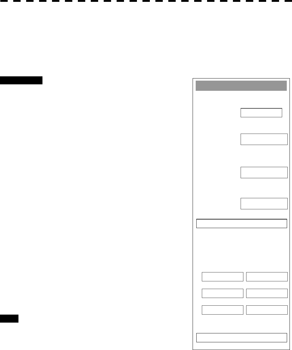
8─77
DGPS Settin
g
1. Mode
A
UTO
0. EXIT
2. Frequency
5. Send Data
275.0KHz
3. Baud Rate (BPS)
50
4. DGPS Mode
ON
Status
No Beacon RCV connection
Frequency --- KHz
Baud Rate --- Baud
RSSI ---
Setting in DGPS Receiver (DGPS Setting)
Set an initial value in the DGPS receiver (our DGPS receiver).
[I] DGPS Mode Setting (Mode)
Procedures 1 Press [RADAR MENU] key twice.
The Radar Menu will appear.
2 Press [7] key.
NAV Equipment Setting Menu will appear.
3 Press [7] key.
GPS Setting Menu will appear.
4 Press [2] key.
DGPS Setting Menu will appear.
5 Press [1] key.
Each time [1] key is pressed, AUTO/MANUAL
is toggled.
Auto: Automatically sets the working
frequency of Beacon station.
Manual: Manually sets the working
frequency.
(From the next page)
6 After having entered the value, press
[5] key to transmit the setting contents
to the DGPS receiver.
Exit 1 Press [RADAR MENU] key.
The Main Menu will reappear.
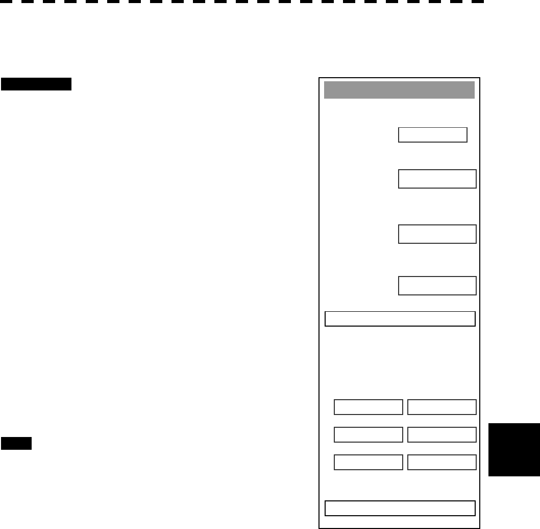
8─78
8
8.6 Setting
DGPS Settin
g
1. Mode
A
UTO
0. EXIT
2. Frequency
5. Send Data
275.0KHz
3. Baud Rate (BPS)
50
4. DGPS Mode
ON
Status
No Beacon RCV connection
Frequency --- KHz
Baud Rate --- Baud
RSSI ---
[II] Setting of Working Frequency of Beacon Station (Frequency)
This setting can be made only when Manual is selected in 1. Mode.
Procedures 1 Press [RADAR MENU] key twice.
The Radar Menu will appear.
2 Press [7] key.
NAV Equipment Setting Menu will appear.
3 Press [7] key.
GPS Setting Menu will appear.
4 Press [2] key.
DGPS Setting Menu will appear.
5 Press [2] key.
The Code Input menu will appear.
Enter the working frequency of the Beacon
station.
The multi-function control is also available for
the entry.
6 After having entered the value, press
[5] key to transmit the setting
contents to the DGPS receiver.
Exit 1 Press [RADAR MENU] key.
The Main Menu will reappear.
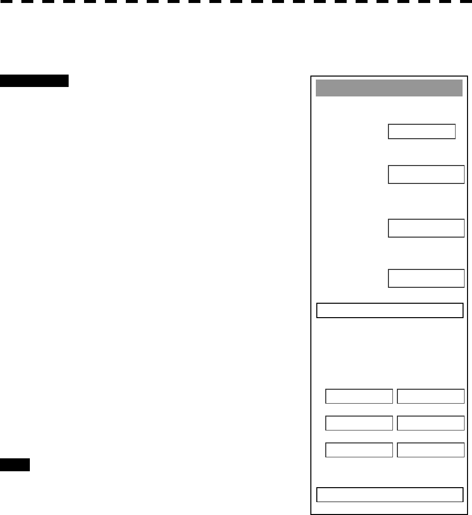
8─79
DGPS Settin
g
1. Mode
A
UTO
0. EXIT
2. Frequency
5. Send Data
275.0KHz
3. Baud Rate (BPS)
50
4. DGPS Mode
ON
Status
No Beacon RCV connection
Frequency --- KHz
Baud Rate --- Baud
RSSI ---
[III] Setting of Communication Baud Rate with Beacon Station (BPS)
This setting can be made only when Manual is selected in 1. Mode.
Procedures 1 Press [RADAR MENU] key twice.
The Radar Menu will appear.
3 Press [7] key.
NAV Equipment Setting Menu will appear.
4 Press [7] key.
GPS Setting Menu will appear.
5 Press [2] key.
DGPS Setting Menu will appear.
6 Press [3] key.
From the pull-down menu, you can select the
following transmission speeds.
50bps
100bps
200bps
Set the desired communication speed.
7 After having entered the value, press
[5] key to transmit the setting contents
to the DGPS receiver.
Exit 1 Press [RADAR MENU] key.
The Main Menu will reappear.
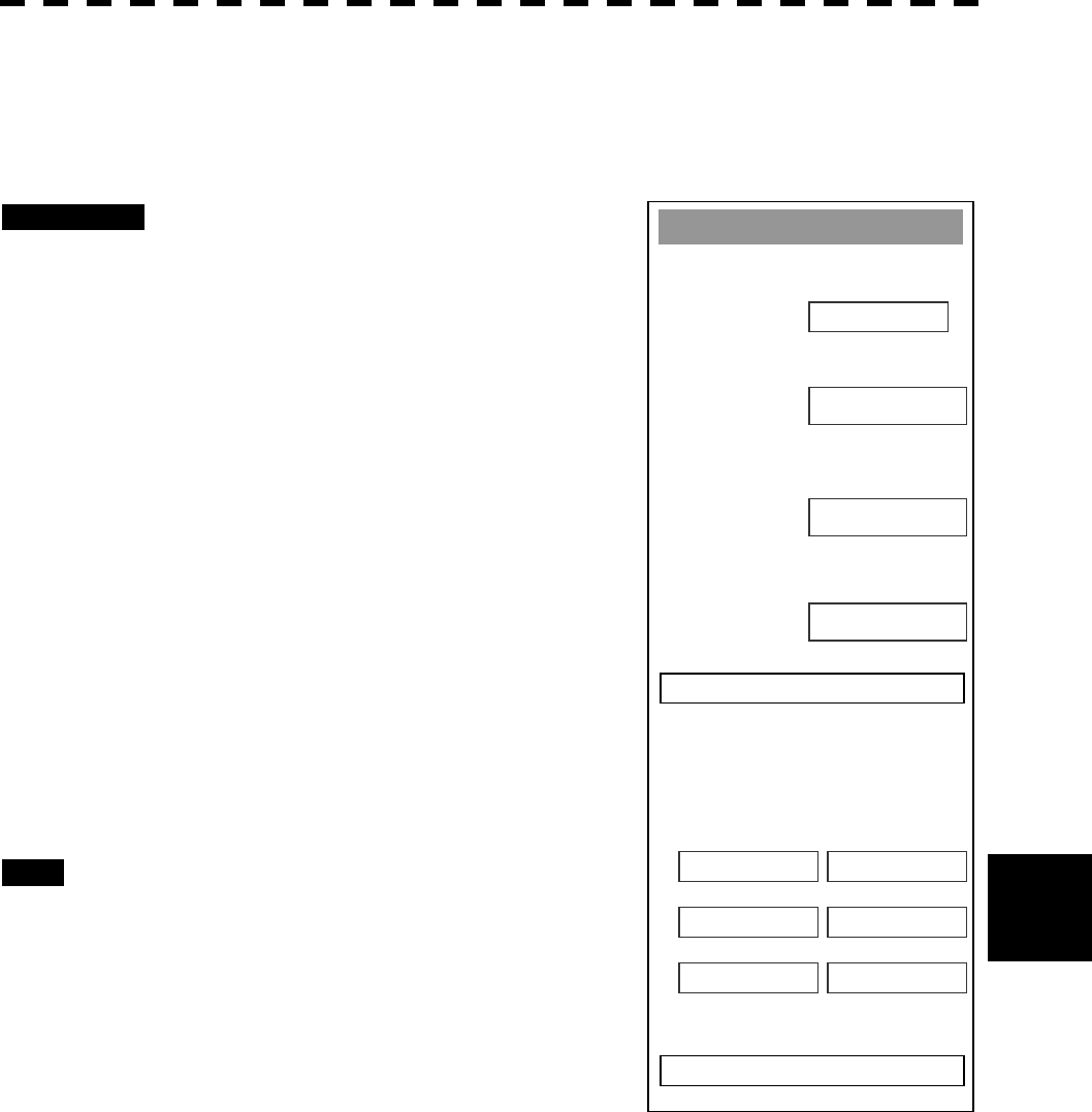
8─80
8
8.6 Setting
DGPS Settin
g
1. Mode
A
UTO
0. EXIT
2. Frequency
5. Send Data
275.0KHz
3. Baud Rate (BPS)
50
4. DGPS Mode
ON
Status
No Beacon RCV connection
Frequency --- KHz
Baud Rate --- Baud
RSSI ---
[IV] DGPS Mode Setting (DGPS Mode)
Set the DGPS mode to ON/OFF. Setting the mode to ON allows you to acquire highly precise position
information by using information from the Beacon station. Setting the mode to OFF allows you to acquire
position information with the same precision as that of GPS.
Procedures 1 Press [RADAR MENU] key twice.
The Radar Menu will appear.
2 Press [7] key.
NAV Equipment Setting Menu will appear.
3 Press [7] key.
GPS Setting Menu will appear.
4 Press [2] key.
DGPS Setting Menu will appear.
5 Press [4] key.
Switching between ON and OFF is done each
time you press [4] key.
6 After having entered the value, press
[5] key to transmit the setting contents
to the DGPS receiver.
Exit 1 Press [RADAR MENU] key.
The Main Menu will reappear.
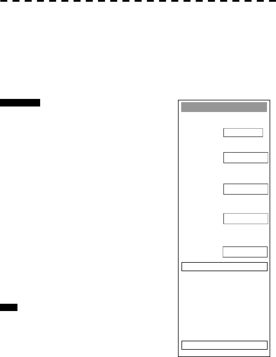
8─81
WAAS Settin
g
1. Mode
A
UTO
0. EXIT
2. Ran
g
in
g
6. Send Data
ON
3. NG WAAS
NOT USE
4. WAAS Select Mode
AUTO
5. WAAS No.
120
Setting in WAAS Receiver (WAAS Setting)
Make settings in the WAAS receiver (our WAAS receiver).
Because the information the WAAS receiver receives from the satellite also includes the same information as
that from DGPS Beacon station, it can perform positioning with higher precision than GPS.
[I] WAAS Mode Setting (Mode)
Set whether or not differential information of the WAAS receiver is acquired from the Beacon or satellite.
Procedures 1 Press [RADAR MENU] key twice.
The Radar Menu will appear.
2 Press [7] key.
NAV Equipment Setting Menu will appear.
3 Press [7] key.
GPS Setting Menu will appear.
4 Press [3] key.
WAAS Setting Menu will appear.
5 Press [1] key.
From the pull-down menu, select the
following:
BEACON,
WAAS, or
AUTO.
6 After having made entry, press [6]
key to transmit the setting contents
to the WAAS receiver.
Exit 1 Press [RADAR MENU] key.
The Main Menu will reappear.
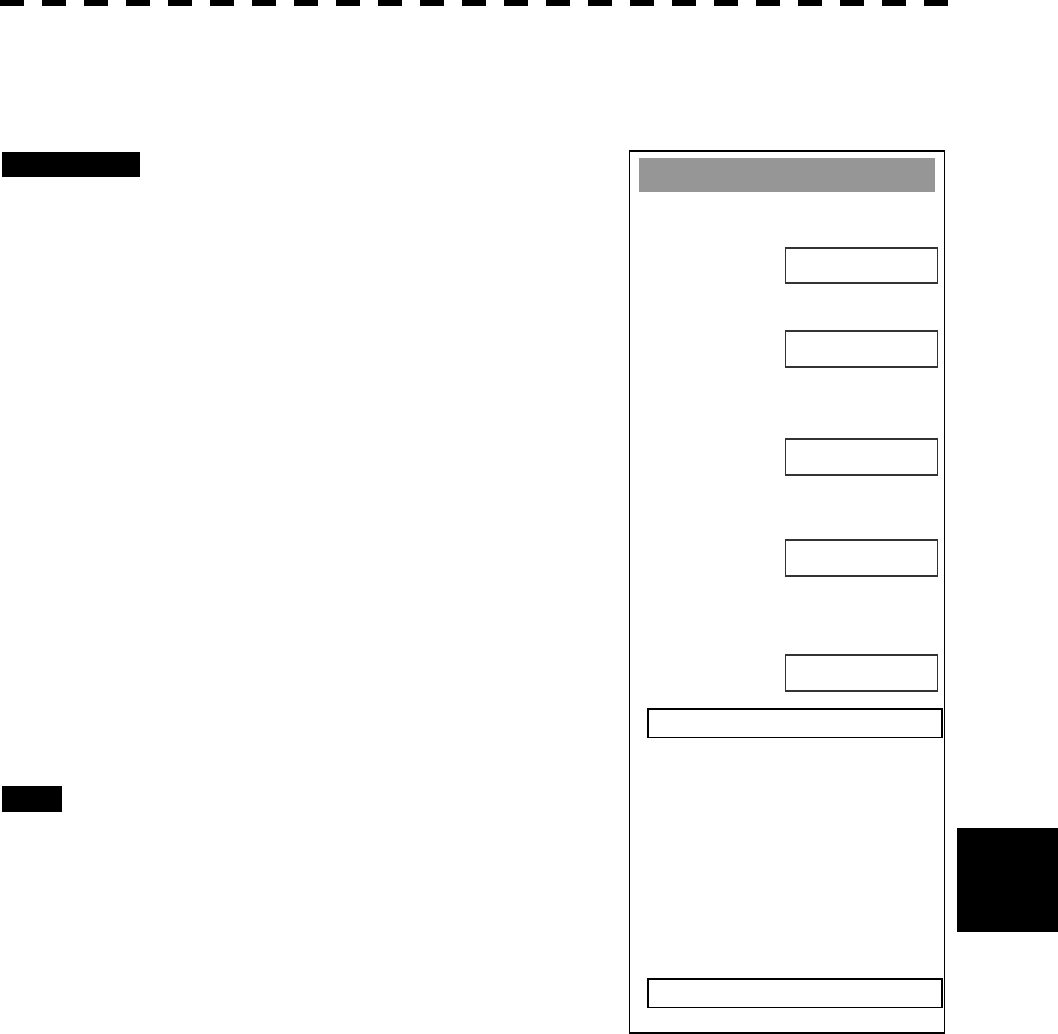
8─82
8
8.6 Setting
WAAS Settin
g
1. Mode
AUTO
0. EXIT
2. Ran
g
in
g
6. Send Data
ON
3. NG W
A
A
S
NOT USE
4. WAAS Select Mode
AUTO
5. WAAS No.
120
[II] Positioning Satellite Selection/Setting (Ranging)
Set whether or not the WAAS satellite is to be used as a positioning satellite.
Procedures 1 Press [RADAR MENU] key twice.
The Radar Menu will appear.
2 Press [7] key.
NAV Equipment Setting Menu will appear.
3 Press [7] key.
GPS Setting Menu will appear.
4 Press [3] key.
WAAS Setting Menu will appear.
5 Press [2] key.
Switching between ON (use) and OFF (not use)
is done each time you press [2] key.
6 After having made entry, press [6] key
to transmit the setting contents to the
WAAS receiver.
Exit 1 Press [RADAR MENU] key.
The Main Menu will reappear.
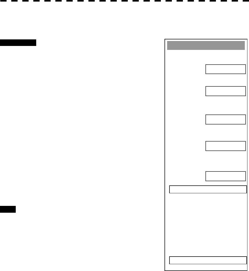
8─83
WAAS Settin
g
1. Mode
AUTO
0. EXIT
2. Ran
g
in
g
6. Send Data
ON
3. NG WAAS
NOT USE
4. WAAS Select Mode
AUTO
5. WAAS No.
120
[III] Setting of Availability of Banned Satellite (NG WAAS)
Set whether or not the information from the banned WAAS satellite is to be used.
Procedures 1 Press [RADAR MENU] key twice.
The Radar Menu will appear.
2 Press [7] key.
NAV Equipment Setting Menu will appear.
3 Press [7] key.
GPS Setting Menu will appear.
4 Press [3] key.
WAAS Setting Menu will appear.
5 Press [2] key.
Switching between USE (use) and NOT USE
(not use) is done each time you press [2] key.
6 After having made entry, press [6] key
to transmit the setting contents to the
WAAS receiver.
Exit 1 Press [RADAR MENU] key.
The Main Menu will reappear.
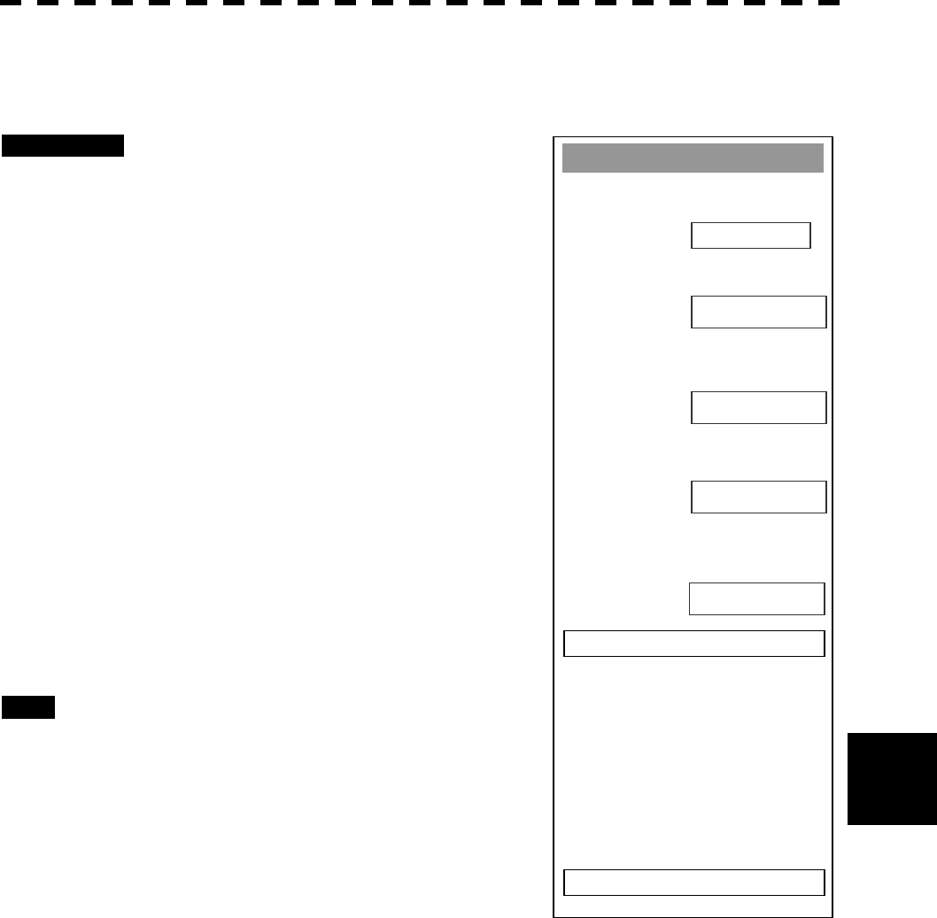
8─84
8
8.6 Setting
WAAS Settin
g
1. Mode
A
UTO
0. EXIT
2. Ran
g
in
g
6. Send Data
ON
3. NG WAAS
NOT USE
4. WAAS Select Mode
AUTO
5. WAAS No.
120
[IV] Satellite Number Setting (WAAS Select Mode)
Set the number of the WAAS satellite to be used.
Procedures 1 Press [RADAR MENU] key twice.
The Radar Menu will appear.
2 Press [7] key.
NAV Equipment Setting Menu will appear.
3 Press [7] key.
GPS Setting Menu will appear.
4 Press [3] key.
WAAS Setting Menu will appear.
5 Press [4] key.
Switching between Auto and Manual is done
each time you press [4] key.
6 After having made entry, press [6] key
to transmit the setting contents to the
WAAS receiver.
Exit 1 Press [RADAR MENU] key.
The Main Menu will reappear.
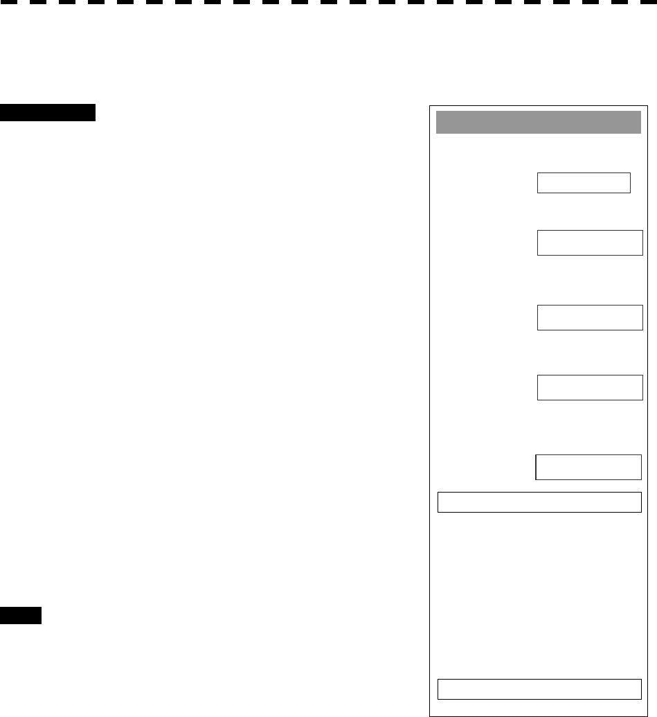
8─85
WAAS Settin
g
1. Mode
A
UTO
0. EXIT
2. Ran
g
in
g
6. Send Data
ON
3. NG WAAS
NOT USE
4. WAAS Select Mode
AUTO
5. WAAS No.
120
[V] Satellite Number Setting (WAAS Select Mode)
Set the number of the WAAS satellite to be used.
Procedures 1 Press [RADAR MENU] key twice.
The Radar Menu will appear.
2 Press [7] key.
NAV Equipment Setting Menu will appear.
3 Press [7] key.
GPS Setting Menu will appear.
4 Press [3] key.
WAAS Setting Menu will appear.
5 Press [5] key.
The Code Input menu will appear.
Enter numeric values between Nos.120 and
138.
The multi-function control is also available to
enter the values.
6 After having made entry, press [6] key
to transmit the setting contents to the
WAAS receiver.
Exit 1 Press [RADAR MENU] key.
The Main Menu will reappear.

8─86
8
8.6 Setting
GPS Settin
g
1. GPS Process Settin
g
0. EXIT
2. DGPS Settin
g
3. WAAS Settin
g
4. GPS Status
GPS Reception Status Display (GPS Status)
Display the reception status of the GPS receiver (GPS, DGPS and WAAS receivers) currently connected.
Seize the status of satellites that are currently performing positioning.
Procedures 1 Press [RADAR MENU] key twice.
The Radar Menu will appear.
2 Press [7] key.
NAV Equipment Setting Menu will appear.
3 Press [7] key.
GPS Setting Menu will appear.
4 Press [4] key.
GPS Status Menu will appear.
Exit 1 Press [0] key.
The Status Menu will be closed.
2 Press [RADAR MENU] key.
The menu will be closed.
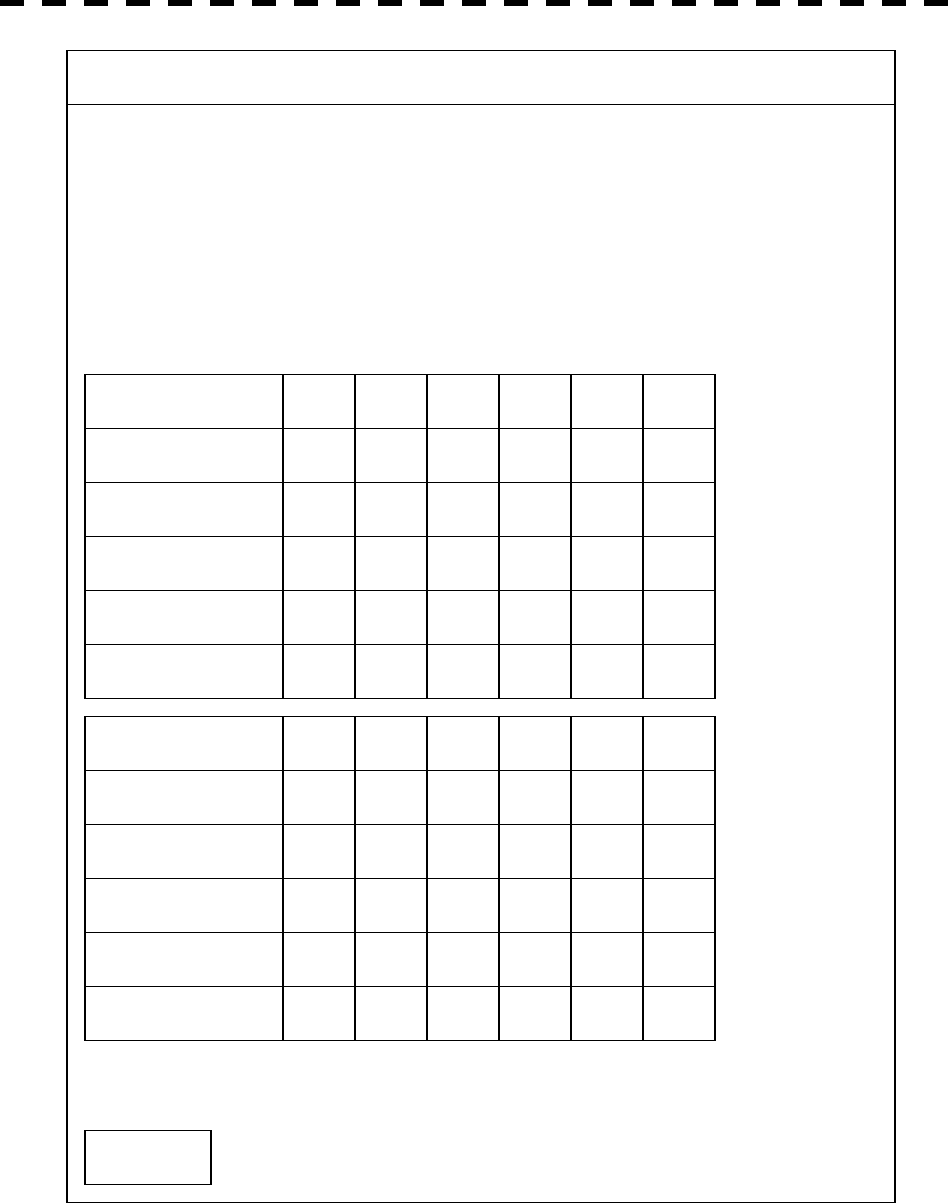
8─87
GPS Status Display
DATE /TIME - - - - - -
(UTC) - - -
L/L - - -
- - -
FIX MODE - - -
ALT - - -
DOP LEVEL - - -
SATELLITE No.
FIX
AZIMUTH
ELEVATE
LEVEL
STATUS
- - - - - - - - - - - - - - - - - -
- - - - - - - - - - - - - - - - - -
- - - - - - - - - - - - - - - - - -
- - - - - - - - - - - - - - - - - -
- - - - - - - - - - - - - - - - - -
- - - - - - - - - - - - - - - - - -
SATELLITE No.
FIX
AZIMUTH
ELEVATE
LEVEL
STATUS
- - - - - - - - - - - - - - - - - -
- - - - - - - - - - - - - - - - - -
- - - - - - - - - - - - - - - - - -
- - - - - - - - - - - - - - - - - -
- - - - - - - - - - - - - - - - - -
- - - - - - - - - - - - - - - - - -
0. EXIT
RSSI - - -
GPS STATUS

8─88
8
8.6 Setting
The following items are to appear on the Status display.
DATE/TIME : Local date and time
(UTC) : Greenwich Mean Time
L/L : Current latitude and longitude
FIX MODE : Fix Mode (2D positioning/3D positioning)
ALT : Altitude of own ship. Setting the Fix Mode to 2D displays the antenna height initially
set.
DOP LEVEL : Precision of positioning results. As the value is smaller, the indicated precision is
higher.
SATELLITE No. : Satellite No.
FIX : Is positioning data used?
AZIMUTH : Azimuthal angle of satellite
ELEVATE : Elevation angle of satellite
LEVEL : Reception signal level
STATUS : Current status of satellite
RSSI : Reception intensity of Beacon station
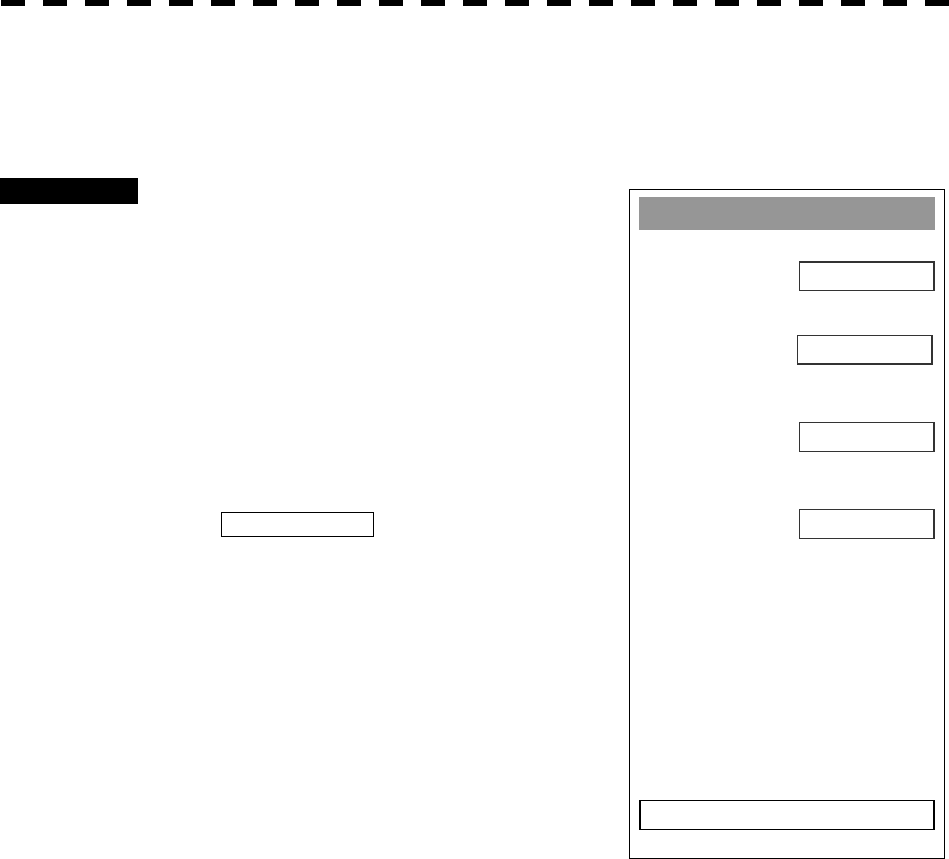
8─89
Date/Time Settin
g
1. UTC/LOCAL
OFF
2. Local Date
1971/01/01
00:00
0. EXIT
3. Local Time
+00:00
4. Time Zone
Date/Time Display Setting (Date/Time Setting)
In displaying the time, it is necessary to set the LOCAL TIME, LOCAL DATE and GMT+/-.
Procedures 1 Press [RADAR MENU] key twice.
The RADAR Menu will appear.
2 Press [8] key.
The RADAR SUB Menu will appear.
3 Press [4] key.
The Date/Time Setting Menu will appear.
4 Press [1] key.
1. UTC/LOCAL will be selected.
The setting is switched back and forth between
UTC (Coordinate Universal Time) and LOCAL
(local time) each time [1] key is pressed.
5 Press [2] key.
The Code Input Menu will appear.
6 Enter the date.
The date will be set. The multi-function control
is also available for the entry.
After having enter the date, press ENT.
7 Press [3] key.
The Code Input Menu will appear.

8─90
8
8.6 Setting
8 Enter the time.
The time will be set. The multi-function control is also available for the entry.
After having enter the time, press ENT.
9 Press [4] key.
The Code Input Menu will appear.
10 Enter the time difference.
The time difference will be set. The multi-function control is also available for the entry.
After having enter the value, press ENT.
Exit 1 Press [RADAR MENU] key.
The menu will be closed.
l Time correction is not available when the “ZDA”
sentence of NMEA0183 is not received.
Attention
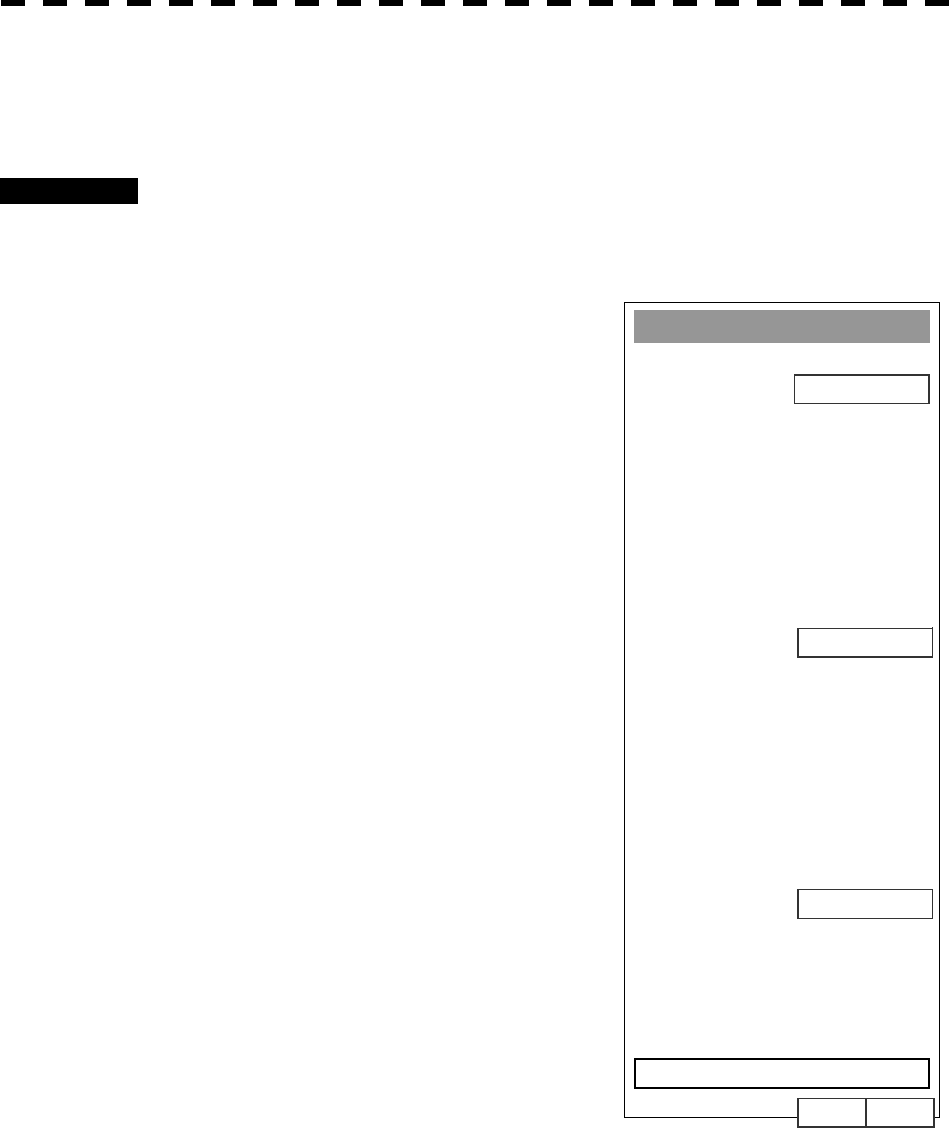
8─91
Adjustment of Performance Monitor (NJU-63/64)
* Execution of this item needs a PM unit (option).
Procedures 1 Set the radar to Master Radar when the Interswitch is installed.
2 Press VRM1 key to display VRM1 and set the range of VRM1 to 10-18*
NM.
3 The Equipment Setup Menu will
appear in accordance with the
instructions of section 8.5.
4 Press [4] key.
The TRX Setting Menu will appear.
5 Press [4] key.
The Code Input Menu will appear.
6 Enter a set value.
Adjust the PM pattern so that its outer edge is
within 10 to 18 NM. The multi-function control
is also available for the entry. After having
enter the value, press ENT.
7 Attach the INFORMATION LABEL
provided with the performance
monitor to an appropriate position on
the display unit.
TRX Settin
g
1. Antenna Hei
g
ht
5-10m
8. Antenna Location
0. EXIT
0
4. PM Ad
j
ustment
2048
7. Output Pulse
0m 0m
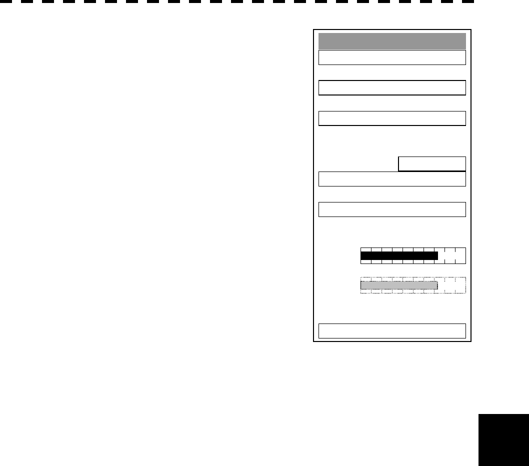
8─92
8
8.6 Setting
8 Press [RADAR MENU] key twice.
The RADAR Menu will appear.
9 Press [8] key.
The RADAR Sub Menu will appear.
10 Press [9] key.
The Test Menu will appear.
11 Press [4] key, and set PM Display to
ON.
The PM bar will appear.
12 Write the value indicated by the PM
bar and the check date to the
INFORMATION LABEL you have
attached to the display unit in step 7.
Test Menu
1. Self Test
2. Monitor Test
3. Panel Test
4. PM Display
ON
5. Error Lo
gg
in
g
6. System INFO
0. EXIT
MAGI
PM
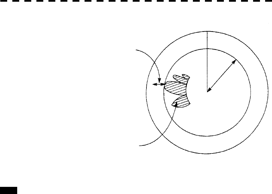
8─93
Exit 1 Press [RADAR MENU] key.
The menu will be closed.
Note: · All target acquisitions by ARPA functions will be cancelled when PM is ON.
The target acquisition cancelled will not be recovered.
· The radar image is suppressed to make the PM image easier to see.
Therefore, the PM Display should be turned OFF after PM check is completed.
Adjust the PM pattern using the ten-key
or multi-function control so that its outer
edge is within 10 to 18 NM.
PM Pattern
10 to
18 NM
HL