Japan Radio NKE2632 Solid State S-Band Marine Radar User Manual Instruction Manual Operation Part 1
Japan Radio Co Ltd. Solid State S-Band Marine Radar Instruction Manual Operation Part 1
Contents
- 1. Installation Manual Part 1
- 2. Installation Manual Part 2
- 3. Installation Manual Part 3
- 4. Installation Manual Part 4
- 5. Installation Manual Part 5
- 6. Installation Manual Part 6
- 7. Installation Manual Part 7
- 8. Installation Manual Part 8
- 9. Installation Manual Part 9
- 10. Installation Manual Part 10
- 11. Installation Manual Part 11
- 12. Instruction Manual Operation Part 1
- 13. Instruction Manual Operation Part 2
- 14. Instruction Manual Operation Part 3
- 15. Instruction Manual Operation Part 4
- 16. Instruction Manual Funtion Part 1
- 17. Instruction Manual Funtion Part 2
- 18. Instruction Manual Funtion Part 3
- 19. Instruction Manual Funtion Part 4
- 20. Instruction Manual Funtion Part 5
- 21. Instruction Manual Funtion Part 6
Instruction Manual Operation Part 1

Overview
1
Name and Function of Each Unit
2
Common Basic Operations
3
Range and Bearing Measurement Methods
4
Basic Operation of the Radar
5
Target Tracking and AIS
6
True and False Echoes on Display
7
Functions of the ECDIS (Option)
8
Route Planning
9
Route Monitoring
10
Monitoring a Dragging Anchor
11
Automatic Sailing (Option)
12
Operating a Chart (Option)
13
Creating a User Map/ Updating a Chart
Manually
14
Logbook
15
Setting Up Screen View
16
Setting Up Alerts
17
Setting Up the Operation Mode
18
Adjusting and Setting Up Equipment (for
Services)
19
Playing Back Data Recorded During
Navigation [Playback]
20
Maintenance & Inspection
21
Failures and After-Sale Services
22
About Disposal
23
Specifications
24
Radar Antenna Block Diagrams
APP A
Alert List
APP B
Setting the Interswitch
APP C
Menu List and Materials
APP D
JMR-7230-S3/S
JMR-7225-7X3/9X3/6X/9X/6XH
JMR-7210-6X/6XH
JMR-7272-S
JMR-7282-S/SH
JMR-9230-S3/S
JMR-9225-7X3/9X3/6X/9X/6XH
JMR-9210-6X/6XH
JMR-9272-S
JMR-9282-S/SH
Marine Radar Equipment
Instruction Manual
<Basic Operation>
iii
PREFACE
Thank you for purchasing the JRC Multi Function Display JMR-7200/JMR-9200 Series.
This equipment meets the performance standards of the IMO (International Maritime
Organization) and the IHO (International Hydro graphic Organization), and serves to improve
safety, reduce fuel combustion, concentrate voyage information as the main device of the INS
(Integrated Navigation System).
z For the best operation, read this manual thoroughly before use.
z Keep this manual in a convenient place for future reference.
Make use of this manual when experiencing operation difficulties.
z The LCD of this equipment uses thin film transistors (TFT). If some pixels on the screen
are not clear, the color is different, or the screen is brighter than usual, it is not because of
defect, instead it is because of inherent characteristic of the TFT display technology.
z The information in this manual is subject to change without notice at any time.
7ZPNA4446A

iv
Safety Cautions
Cautions for High Voltage
High voltages, ranging from several hundreds to tens of thousands of volts, are used in
electronic apparatus, such as radio and radar instruments. These voltages are totally harmless
in most operations. However, touching a component inside the unit is very dangerous. (Any
person other than authorized service engineers should not maintain, inspect, or adjust the unit.)
High voltages on the order of tens of thousand volts are most likely to cause instant deaths from
electrical shocks. At times, even voltages on the order of several hundred volts could lead to
electrocution. To defend against electrical shock hazards, don't put your hand into the inside of
apparatus.
When you put in a hand unavoidably in case of urgent, it is strongly suggested to turn off the
power switch and allow the capacitors, etc. to discharge with a wire having its one end positively
grounded to remove residual charges. Before you put your hand into the inside of apparatus,
make sure that internal parts are no longer charged. Extra protection is ensured by wearing dry
cotton gloves at this time. Another important precaution to observe is to keep one hand in your
pocket at a time, instead of using both hands at the same time. It is also important to select a
secure footing to work on, as the secondary effects of electrical shock hazards can be more
serious. In the event of electrical shocks, disinfect the burnt site completely and obtain medical
care immediately.
Precautions for Rescue of Victim
of Electric Shock
When a victim of electric shock is found, turn off the power source and ground the circuit
immediately. If this is impossible, move the victim away from the unit as quick as possible without
touching him or her with bare hands. He or she can safely be moved if an insulating material
such as dry wood plate or cloth is used.
It is necessary to perform first aid immediately.
Breathing may stop if current flows through the respiration center of brain due to electric shock. If
the electric shock is not large, breathing can be restored by artificial respiration. A victim of
electric shock looks pale and his or her pulse may become very weak or stop, resulting in
unconsciousness and rigidity at worst.
Emergency Measures

v
Method of First-Aid Treatment
Precautions for First-Aid Treatments
Apply artificial respiration to the person who collapsed, minimizing moving as much as
possible avoiding risks. Once started, artificial respiration should be continued rhythmically.
(1) Refrain from touching the patient carelessly as a resultof the accident; the first-aider
could suffer from electrical shocks by himself or herself.
(2) Turn off the power calmly and certainly, and move the patient apart from the cable
gently.
(3) Call or send for a physician or ambulance immediately, or ask someone to call doctor.
(4) Lay the patient on the back, loosening the necktie, clothes, belts and so on.
(5) (a) Feel the patient's pulse.
(b) Check the heartbeat by bringing your ear close to the patient's heart.
(c) Check for respiration by bringing your face or the back of your hand to the patient's
face.
(d) Check the size of patient's pupils.
(6) Opening the patient's mouth, remove artificial teeth, cigarettes, chewing gum, etc. if
any. With the patient's mouth open, stretch the tongue and insert a towel or the like into
the mouth to prevent the tongue from being withdrawn into the throat. (If the patient
clenches the teeth so tight that the mouth won't open, use a screwdriver or the like to
force the mouth open and then insert a towel or the like into the mouth.)
(7) Wipe off the mouth to prevent foaming mucus and saliva from accumulating.

vi
Treatment to Give When the Patient Has a
Pulse Beating but Has Ceased to Breathe
∗ Performing mouth-to-mouth artificial respiration
(1) Bend the patient's face backward until it is directed to look back. (A pillow may be
placed under the neck.)
(2) Pull up the lower jaw to open up the airway. (To spread the airway)
(3) Pinching the patient's nose, breathe deeply and blow your breath into the patient's
mouth strongly, with care to close it completely. Then, move your mouth away and
take a deep breath, and blow into his or her mouth. Repeat blowing at 10 to 15 times
a minute (always with the patient's nostrils closed).
(4) Continue artificial respiration until natural respiration is restored.
(5) If the patient's mouth won't open easily, insert a pipe, such as one made of rubber or
vinyl, into either nostril. Then, take a deep breath and blow into the nostril through
the pipe, with the other nostril and the mouth completely closed.
(6) The patient may stand up abruptly upon recovering consciousness. Keep the patient
lying calmly, giving him or her coffee, tea or any other hot drink (but not alcoholic
drink) to keep him or her warm.
Mouth-to-mouth artificial respiration with the patient's head lifted
[1]
(1) Lift the back part of the patient's
head. Support the forehead with one
of your hand and the neck with the
other hand.→ [1].
Many patients will have their airways
opened by lifting their head in this
way to ease mouth-to-mouth
artificial respiration.
[2]
(2)
Closing the patient's mouth with your
mouth, press your cheek against the
patient's nose→ [2].
Alternatively, hold the patient's nose
with your finger to prevent air leak
→ [3].
[3]
(3) Blowing air into the patient's lungs.
Blow air into the patient's lungs until
chest is seen to rise. The first 10
breaths must be blown as fast as
possible.
Fig. 1 Mouth-to-mouth artificial respiration
vii
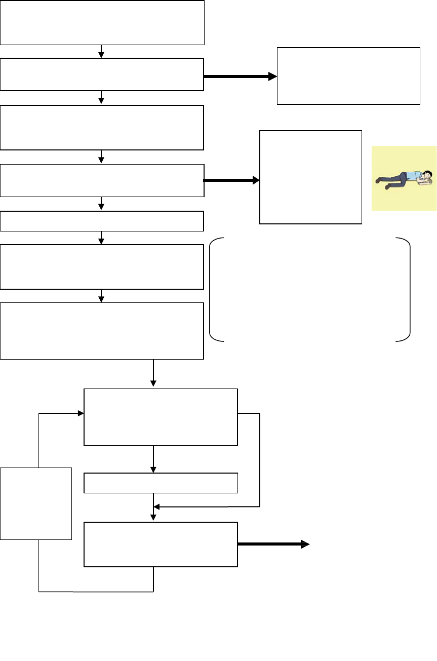
Flow of Cardiopulmonary Resuscitation (CPR)
A person is collapsing.
- Secure the safety of the surrounding area.
- Prevent secondary disasters.
Check for response.
-
Call while tapping the shoulder.
Breathing
Recovery position
- Lay the injured or
ill person on
his/her side and
wait for the arrival
of the emergency
services.
Not responding
Ask for help.
- Make an emergency call.
-
Ask to bring an AED.
Listen to the appeal of the
injured or ill person and give
the necessary first-aid
treatment.
Responding
Not breathing
Give 2 rescue breaths; omittable Note(
1
)
Give CPR.
- 30 chest compressions
-
Give 2 rescue breaths; omittable Note(
1
)
Note(1) Omission of rescue breathing:
If there is a fear of infection because the
injured or ill person has an intraoral injury,
you are hesitant about giving mouth
-to-
mouth
resuscitation,
or preparing the mouthpiece for
rescue breathing takes too long, omit rescue
breathing and proceed to the next step.
Open the airway.
-
Check for breathing.
Arrival of an AED
- Turn on the power.
- Use the AED by following its voice prompts.
Fitting of the electrode pads, etc.
Automatic electrocardiogram
analysis
- Do not touch the injured or ill
person.
Electric shock is needed.
Electric shock is not needed.
Delivery of electric shock
Resume CPR from chest
compressions by following the
voice prompts of the AED.
When the injured or ill
person has been
handed over to the
emergency services or
has started moaning or
breathing normally, lay
him/her on his/her side
in a recovery position
and wait for the arrival
of emergency services.
When to
stop CPR
A person is collapsing.
- Secure the safety of the surrounding area.
- Prevent secondary disasters.
The AED
automatically
analyzes the
heart rhythm
every 2 min.

viii
Specific Procedures for Cardiopulmonary Resuscitation (CPR)
1. Check the scene for safety to prevent secondary disasters
a) Do not touch the injured or ill person in panic when an accident
has occurred. (Doing so may cause electric shock to the
first-aiders.)
b) Do not panic and be sure to turn off the power. Then, gently move
the injured or ill person to a safe place away from the electrical
circuit.
2. Check for responsiveness
a) Tap the shoulder of the injured or ill and shout in the ear saying, "Are you OK?"
b) If the person opens his/her eyes or there is some response or gesture, determine it as
"responding." But, if there is no response or gesture, determine it as "not responding."
3. If responding
a) Give first-aid treatment.
4. If not responding
a) Ask for help loudly. Ask somebody to make an emergency call
and bring an AED.
• Somebody has collapsed. Please help.
• Please call an ambulance.
• Please bring an AED.
• If there is nobody to help, call an ambulance yourself.
5. Open the airway
a) Touch the forehead with one hand. Lift the chin with the two fingers
of the middle finger and forefinger of the other hand and push down
on the forehead as you lift the jaw to bring the chin forward to open
the airway. If neck injury is suspected, open the airway by lifting the
lower jaw.
6. Check for breathing
a) After opening the airway, check quickly for breathing for no more than
10 seconds. Put your cheek down by the mouth and nose area of the
injured or ill person, look at his/her chest and abdomen, and check the following three points.
• Look to see if the chest and abdomen are rising and falling.
• Listen for breathing.
• Feel for breath against your cheek.
Are you OK?
Please call an
ambulance.
Please bring an AED.
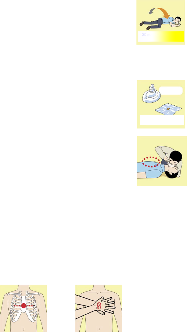
ix
b) If the injured or ill person is breathing, place him/her in the recovery
position and wait for the arrival of the emergency services.
• Position the injured or ill person on his/her side, maintain a clear
and open airway by pushing the head backward while positioning
their mouth downward. To maintain proper blood circulation, roll
him/her gently to position them in the recovery position in the
opposite direction every 30 minutes.
7. Give 2 rescue breaths (omittable)
a) If opening the airway does not cause the injured or ill person to begin
to breathe normally, give rescue breaths.
b) If there is a fear of infection because the injured or ill person has an
intraoral injury, you are hesitant about giving mouth-to-mouth
resuscitation, or getting and preparing the mouthpiece for rescue
breathing takes too long, omit rescue breathing and perform chest
compressions.
c) When performing rescue breathing, it is recommended to use a
mouthpiece for rescue breathing and other protective devices to
prevent infections.
d) While maintaining an open airway, pinch the person's nose shut with
your thumb and forefinger of the hand used to push down the
forehead.
e) Open your mouth widely to completely cover the mouth of the injured or ill person so that no air
will escape. Give rescue breathing twice in about 1 second and check if the chest rises.
8. Cardiopulmonary resuscitation (CPR) (combination of chest compressions and
rescue breaths)
a) Chest compressions
1) Position of chest compressions
• Position the heel of one hand in the center of the chest, approximately between the
nipples, and place your other hand on top of the one that is in position.
Roll gently in the opposite
direction every 30 minutes.
CPR mask
Mouthpiece for rescue
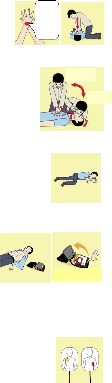
x
2) Perform chest compressions
• Perform uninterrupted chest compressions of
30 at the rate of about 100 times per minute.
While locking your elbows positioning yourself
vertically above your hands.
• With each compression, depress the chest wall to a depth of approximately 4 to 5 cm.
b) Combination of 30 chest compressions and 2 rescue breaths
1) After performing 30 chest compressions, give 2 rescue
breaths. If rescue breathing is omitted, perform only chest
compressions.
2) Continuously perform the combination of 30 chest
compressions and 2 rescue breaths without interruption.
3) If there are two or more first-aiders, alternate with each other
approximately every two minutes (five cycles of compressions
and ventilations at a ratio of 30:2) without interruption.
9. When to stop cardiopulmonary resuscitation (CPR)
a) When the injured or ill person has been handed over to the
emergency services
b) When the injured or ill person has started moaning or breathing
normally, lay him/her on his/her side in a recovery position and wait
for the arrival of emergency services.
10. Arrival and preparation of an AED
a) Place the AED at an easy-to-use position. If
there are multiple first-aiders, continue CPR
until the AED becomes ready.
b) Turn on the power to the AED unit.
Depending on the model of the AED, you
may have to push the power on button, or the AED automatically turns on when you open the
cover.
c) Follow the voice prompts of the AED.
11. Attach the electrode pads to the injured or ill person's bare chest
a) Remove all clothing from the chest, abdomen, and arms.
b) Open the package of electrode pads, peel the pads off and securely
place them on the chest of the injured or ill person, with the adhesive
side facing the chest. If the pads are not securely attached to the chest,
the AED may not function. Paste the pads exactly at the positions
30 times
Compress
with these
parts (the
heels of
both
hands).
2 times
Turn on the power.

xi
indicated on the pads, If the chest is wet with water, wipe dry with a dry
towel and the like, and then paste the pads. If there is a pacemaker or
implantable cardioverter defibrillator (ICD), paste the pads at least 3cm
away from them. If a medical patch or plaster is present, peel it off and
then paste the pads. If the injured or ill person's chest hair is thick,
paste the pads on the chest hair once, peel them off to remove the
chest hair, and then paste new pads.
c) Some AED models require to connect a connector by following voice prompts.
d) The electrode pads for small children should not be used for children over the age of 8 and for
adults.
12. Electrocardiogram analysis
a) The AED automatically analyzes electrocardiograms. Follow the
voice prompts of the AED and ensure that nobody is touching the
injured or ill person while you are operating the AED.
b) On some AED models, you may need to push a button to analyze
the heart rhythm.
13. Electric shock (defibrillation)
a) If the AED determines that electric shock is needed, the voice
prompt saying, "Shock is needed" is issued and charging starts
automatically.
b) When charging is completed, the voice prompt saying, "Press the
shock button" is issued and the shock button flashes.
c) The first-aider must get away from the injured or ill person, make
sure that no one is touching him/her, and then press the shock button.
d) When electric shock is delivered, the body of the injured or ill person may jerk.
14. Resume cardiopulmonary resuscitation (CPR).
Resume CPR consisting of 30 chest compressions
and 2 rescue breaths by following the voice
prompts of the AED.
15. Automatic electrocardiogram analysis
a) When 2 minutes have elapsed since you resumed cardiopulmonary resuscitation (CPR), the
AED automatically analyzes the electrocardiogram.
b) If you suspended CPR by following voice prompts and AED voice prompt informs you that
shock is needed, give electric shock again by following the voice prompts.
If AED voice prompt informs you that no shock is needed, immediately resume CPR.
Press the shock button.

xii
16. When to stop CPR (Keep the electrode pads on.)
a) When the injured or ill person has been handed over to the emergency services
b) When the injured or ill person has started moaning or breathing normally, lay him/her on
his/her side in a recovery position and wait for the arrival of emergency services.
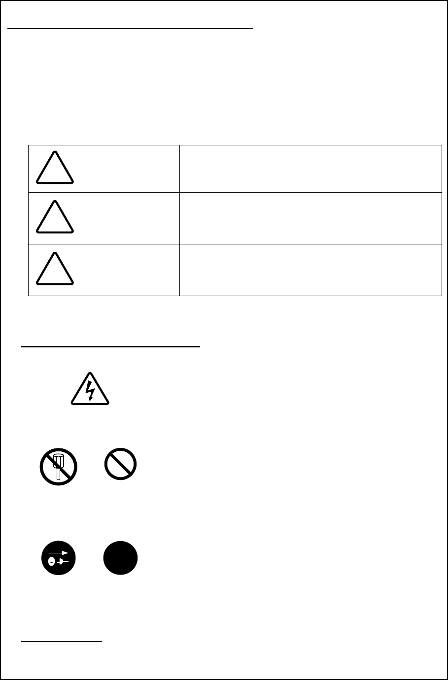
xiii
Pictorial Indication
Meanings of Pictorial Indication
Various pictorial indications are included in this manual and
are shown on this equipment so that you can operate them
safely and correctly and prevent any danger to you and / or
to other persons and any damage to your property during
operation. Such indications and their meanings are as
follows.
Please understand them before you read this manual:
DANGER This indication is shown where incorrect equipment
operation due to negligence may cause death or serious
injuries.
WARNING
This indication is shown where any person is supposed to
be in danger of being killed or seriously injured if this
indication is neglected and this equipment is not operated
correctly.
CAUTION
This indication is shown where any person is supposed to
be injured or any property damage is supposed to occur if
this indication is neglected and this equipment is not
operated correctly.
Examples of Pictorial Indication
Electric Shock
The mark represents CAUTION (including DANGER and
WARNING).
Detailed contents of CAUTION ("Electric Shock" in the example
on the left) is shown in the mark.
Disassembling
Prohibited
The mark represents prohibition.
Detailed contents of the prohibited action ("Disassembling
Prohibited" in the example on the left) is shown in the mark.
Disconnect
the power plug
!
The mark represents instruction.
Detailed contents of the instruction ("Disconnect the power plug"
in the example on the left) is shown in the mark.
Warning Label
There is a warning label on the top cover of the equipment.
Do not try to remove, break or modify the label.
!
!
!
xiv
Precautions upon Equipment Operation
DANGER
Never attempt to check or repair the inside of the equipment.
Checking or repair by an unqualified person may cause a fire or an electric
shock.
Contact our head office, or a nearby branch or local office to request
servicing.
Never remove the cover of this equipment.
Touching the high-voltage section inside will cause an electric shock.
Do not attempt to disassemble or tamper with this equipment.
Otherwise, a fire, an electric shock, or a malfunction may occur.
When conducting maintenance, make sure to turn the main power off.
Failure may result in electric shock.
Turn off all the main powers before cleaning the equipment. Make sure to turn
it off since voltage is still outputted from the rectifier even after the indicator
and the radar are turned off. Failure may result in equipment failure, or death
or serious injury due to electric shock.
When conducting maintenance work on the radar antenna, make sure to turn
all the main powers off.
Failure may result in electric shock or injuries.
Make sure to turn off the radar antenna safety switch. Failure may result in
injuries caused by physical contact with the rotating radar antenna.
xv
When turning off the power supply, do not hold down the power button of the
operation unit.
Otherwise, a trouble may occur due to termination failure.
Never directly touch the internal components of the radar antenna or
indicator. Direct contact with these high-voltage components may cause
electric shock. For maintenance, inspection, or adjustment of equipment
components, consult with our branch office, branch shop, sales office, or our
distributor in your district.
Do not get close to the radiant section of the radar antenna. It is a rotating
part, and it may cause injuries if it suddenly starts rotating and consequently
hits the body. It is recommended that the radiant section be installed at a high
place such as on the roof of the wheelhouse, on the flying bride, on the
trestle, or on the radar mast so that no one can get close to it.
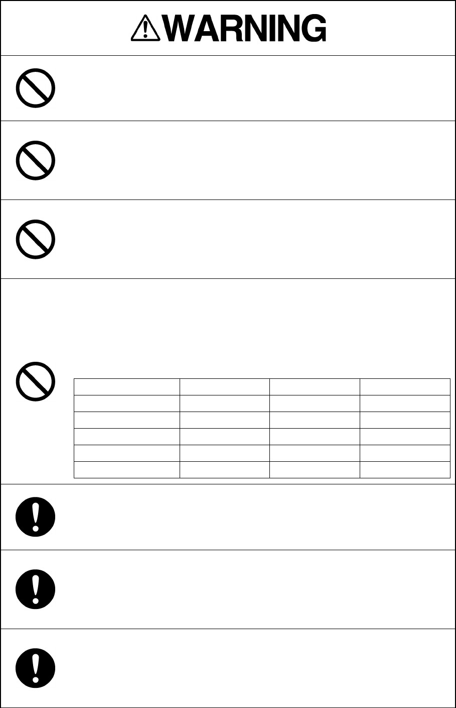
Microwave radiation level of the radar antenna:
Keep away from the radar antenna during transmission.
Microwaves are generated from the front center of the radiant section of the
radar antenna at the levels indicated in the table below. Exposure to
microwaves at close range can result in injury (especially damage to eyes).
Microwave radiation level of the radar antenna
System
50 W/m2
20 W/m2
2.5 W/m2
NKE-2103
n/a
26 cm
123 cm
NKE-1125/1129/2254
5 cm
81 cm
162 cm
NKE-1130/1139
11 cm
76 cm
181 cm
NKE-2632
1.4 cm
3.1 cm
209.8 cm
NKE-1632
1.5 cm
3.3 cm
128.4 cm
Make sure to install the radar antenna at a place higher than human height.
Direct exposure to electromagnetic wave at close range will have adverse
effects on the human body.
When it is necessary to get close to the radar antenna for maintenance or
inspection purposes, make sure to turn the power switch of the display unit to
"OFF" or "STBY".
Direct exposure to electromagnetic waves at close range will have adverse
effects on the human body.
When conducting maintenance work, make sure to turn off the power so that
the power supply to the equipment is completely cut off.
Some equipment components can carry electrical current even after the
power switch is turned off, and conducting maintenance work may result in
electric shock, equipment failure, or accidents.
xvi
When cleaning the display screen, do not wipe it too strongly with a dry cloth.
Also, do not use gasoline or thinner to clean the screen. Failure will result in
damage to the screen surface.
Do not change Initial Level/Area Offset unless absolutely necessary.
Incorrect adjustment will result in deletion of nearby target images and thus
collisions may occur resulting in death or serious injuries.
Confirm computer virus does not exist in USB flash memory beforehand
when reading and writing of the file by using USB flash memory.
Influences other equipment when the display unit is infected with the virus,
and it may cause a breakdown.
Do not remove USB flash memory while the access lamp (in USB flash drive)
is flashing.
Data may be damaged when the USB flash memory is inserted or removed
while accessing it, and it may cause a breakdown.
Do not place a glass or cup containing water, etc., or a small metal object on
this equipment.
If water or such object gets inside, a fire, an electric shock, or a malfunction
may occur.
In case water or a metal object gets inside the equipment, turn off the power
immediately, unplug the power supply cable from an electric outlet, and
contact our head office, or a nearby branch or local office to request servicing.
Keeping the equipment in operation under such condition may cause a fire,
an electric shock or a malfunction.
In case you find smoke, unusual odor or extreme high heat coming from the
equipment, turn off the power immediately, unplug the power supply cable
from an electric outlet, and contact our head office, or a nearby branch or
local office to request servicing.
Keeping the equipment in operation under such condition may cause a fire or
an electric shock.
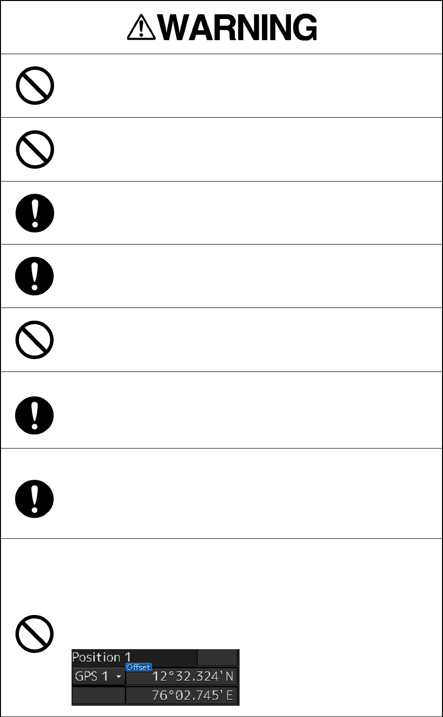
Do not use the offset function during navigation.
If the equipment is used with the offset value entered as the own ship position
(deviated from the actual position), accidents may result.
When the offset values are entered, the [Offset] badge is displayed at the
position display on the Own Ship Information. Check the indication, and
cancel the offset function if necessary. Also, the message "Position Shift" is
displayed in the message display area.
xvii
Before starting automatic sailing, be sure to check the safety of the route and
the safety when crossing safety contour.
Otherwise, accidents may result.
If the own ship has arrived at the boundary of a WPT during automatic sailing,
be sure to check the safety and perform turning manually by the operator
him/herself.
Otherwise, the ship keeps the course with the leg bearing, and accidents may
result.
Input the ship’s parameter accurately according to the specification of the
ship.
Otherwise, accidents may result.
Change of the color of the Day/Night button, particularly the use of the [Night]
color, may interfere with the recognition of display information.
When moving the dialog box, move to the position that does not cover the
operation area. If the dialog box covers the operation area, it may interfere
the recognition of the display information.
Do not apply strong shock to the coaxial cable by striking it with a tool or
hammering it.
Otherwise, an open circuit failure may result.
Do not place anything heavy on the coaxial cable.
Otherwise, an open circuit failure may result.
Do not twist or pull the coaxial cable.
Otherwise, an open circuit failure may result.
xviii
Use the radar only as a navigation aid.
The final navigation decision must always be made by the operator
him/herself.
Making the final navigation decision based only on the radar display
information may cause accidents such as collisions or running aground.
A malfunction as the screen is disordered or unshown may occur if the power
in the ship is instantaneously interrupted during operation of the radar. In this
case, the power should be turned on again.
Use Target Tracking (TT) function only as a navigation aid. The final
navigation decision must always be made by the operator him/herself.
Making the final navigation decision based only on tracking target information
may cause accidents.
Tracking target information such as vector, target numerical data, and alarms
may contain some errors. Also, targets that are not detected by the radar
cannot be acquired or tracked.
Making the final navigation decision based only on the radar display may
cause accidents such as collisions or running aground.
In the short distance range, do not set the sea clutter suppression function so
that all reflections from the sea are suppressed. This suppresses not only the
echo from waves, etc., but also the echo from floating objects such as ships
or dangerous objects, etc., and obstructs their detection.
When using the sea clutter suppression function, always make the best
suppression setting.
Do not set the rain/snow clutter suppression setting to an excessive level,
because not only the echo from rain or snow but also the echo from floating
objects such as ships or dangerous objects, etc., and obstructs their
detection.
When using the rain/snow clutter suppression function, always make the best
suppression setting.
When setting a guard zone, make sure to properly adjust gain, sea-surface
reflection suppression level, and rain/snow reflection suppression level so
that the optimal target images are always on the radar screen. The guard
zone alarm will not be activated for targets undetected by the radar, and it
may result in accidents such as collisions.
The simulation function is used exclusively for deciding whether or not target
tracking is properly operating. Therefore, never use this function unless you
wish to check target tracking operations.
Note especially that, if this function is used during actual navigation,
simulated targets are displayed and may become confused with other actual
targets. Therefore, never use this function during actual navigation.
xix
Since these alarms may include some errors depending on the target tracking
conditions, the navigation officer himself should make the final decision for
ship operations such as collision avoidance.
Making the final navigation decision based only on the alarm may cause
accidents such as collisions.
Optimal values have been set for VD Level and Constant; therefore, never
change their values unless absolutely necessary. Failure may result in
accidents that would lower target tracking performance.
When replacing magnetrons, make sure to shut off the main power and let
the equipment stand for more than 5 minutes to discharge the high-voltage
circuit.
Failure may result in electric shock.
Make sure to take off your watch when your hand must get close to the
magnetron.
Failure may result in damage to the watch since the magnetron is a strong
magnet.
Make sure that two or more staff member work together when replacing the
LCD. If only one person attempts to replace the LCD, he/she may drop it and
become injured.
Do not directly touch the inverter circuit of the LCD display with a bare hand
since high voltage temporarily remains in the circuit even after the main
power is shut off.
Failure may result in electric shock.
Any adjustments must be made by specialized service personnel.
Incorrect settings may result in unstable operation, and this may lead to
accidents or equipment failure.
Do not make any adjustments during navigation.
Failure may result in adverse effects on the radar function which may lead to
accidents or equipment failure.
Do not change the quantization level settings unless absolutely necessary.
If set at an inappropriate value, the acquisition of target tracking function and
the tracking function deteriorate, and this may lead to accidents.
Do not use or leave the equipment under direct sunlight for a long time or in
the temperatures above 55°C.
Otherwise, a fire or a malfunction may occur.
xx
Do not block the ventilation opening of the equipment.
Otherwise, heat may accumulate inside to cause a fire or a malfunction.
This equipment is intended for use as an aid to navigation only.
• If no backup measures, such as using another ECDIS unit for
confirmation, are taken, be sure to use official marine charts together with
this equipment to make any navigational decision.
• This equipment is not designed to assess the positional information
automatically.
The positional information should always be checked by the operator.
Otherwise, accidents may result.
Do not touch the equipment with hands or gloves wet with water.
Otherwise, an electric shock or a malfunction may occur.
Do not leave the disc in the DVD drive.
Malfunctions of the drives may result.
• Do not place any object on the operation panel.
In particular, if a hot object is placed on the operation panel, it can cause
deformation of the surface of the operation panel.
• Do not apply any undue shock on the operation panel, trackball and dials.
Otherwise, a malfunction may result.
Make sure that the main power is turned off before inspection or replacement
of parts.
Otherwise, an electric shock, a fire, or a malfunction may occur.
• If a fan alarm or CPU temperature rise alarm has occurred, immediately
turn off the power.
Keeping the equipment in operation under such condition may cause a fire
or a malfunction.
After turning off the power, contact our head office, or a nearby branch or
local office to request servicing.
Edit routes in accordance with the world geodetic system (WGS-84).
Use of routes edited with any other geodetic systems may cause accidents.

xxi
During sailing, be sure to check the own ship’s position and bearing as often
as necessary, regardless of whether the automatic sailing is in operation or
not.
Otherwise, accidents may result.
Do not turn off the power during Backup/Restore.
Otherwise, a function may fail, and an accident may occur.
Do not do the backup operation of data while sailing.
The radar application should be ended to begin the data backup. It becomes
impossible to observe using radar and this may lead to accidents.
The backup power supply (DC power supply, etc.) of the equipment must be
connected when recovery of the C drive image is performed. If the power
supply stops during recovery, an equipment activation fault occurs, causing
an accident.
Do not turn off the power supply during recovery of C drive image.
Otherwise, a function fault occurs, causing an accident.
Since the image within the previous observation range is displayed by
expanding/contracting for the period from immediately after switching of the
observation range from the next image updating, do not use this image for
navigation.
If this image is used for navigation, an accident may occur.
In the case of turning on the power under the condition of low temperature, do
pre-heat more than 30 minutes.
Otherwise, an operation failure may occur and an accident may occur.
Normally, use the automatic tuning mode.
If you use the manual tuning mode, an accident may be caused by a
transmission/reception problem.
Use the manual tuning mode only when you cannot bet the best tuning
conditions in the automatic tuning mode.
Always keep the sensitivity adjusted to the best condition.
If you raise the sensitivity excessively, the visibility of the target will be
reduced by unwanted signals including receiver noise and pseudo image.
This may cause an accident.
If the sensitivity is reduced excessively, detection of a target such as a ship or
hazardous material will be interrupted.

xxii
Adjust the preset of the observation scene according to the oceanographic
condition, with the thorough understanding of the features of the radar signal
processing setting. The optimum radar performance
may not be able to be
demonstrated due to the contents of the changed setting or the
oceanographic condition at that time.
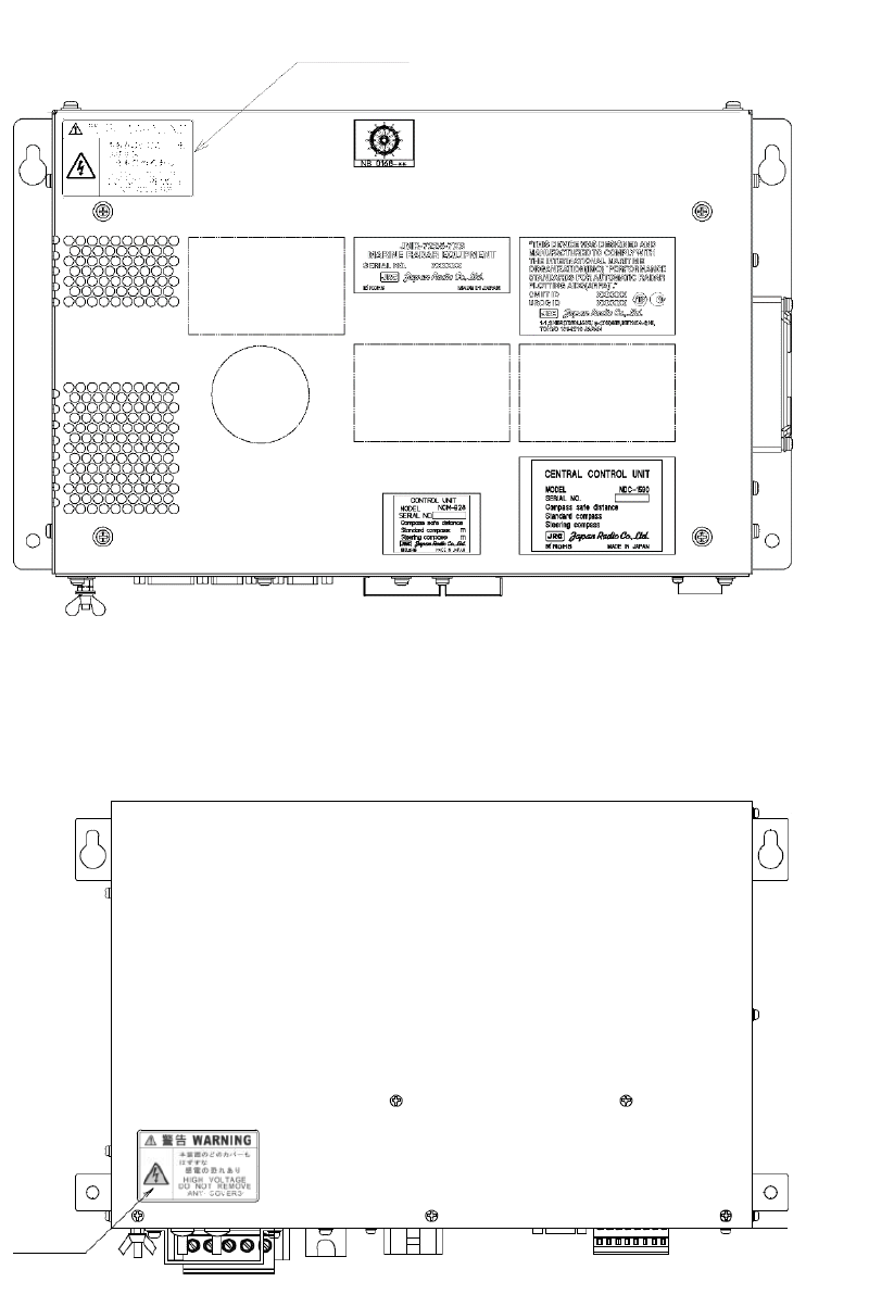
xxiii
The Mounting Point of the Warning Label
NDC-1590 Central Processing Unit
NBD-913 Power Supply Unit
Warning Label
Warning
Label
xxiv
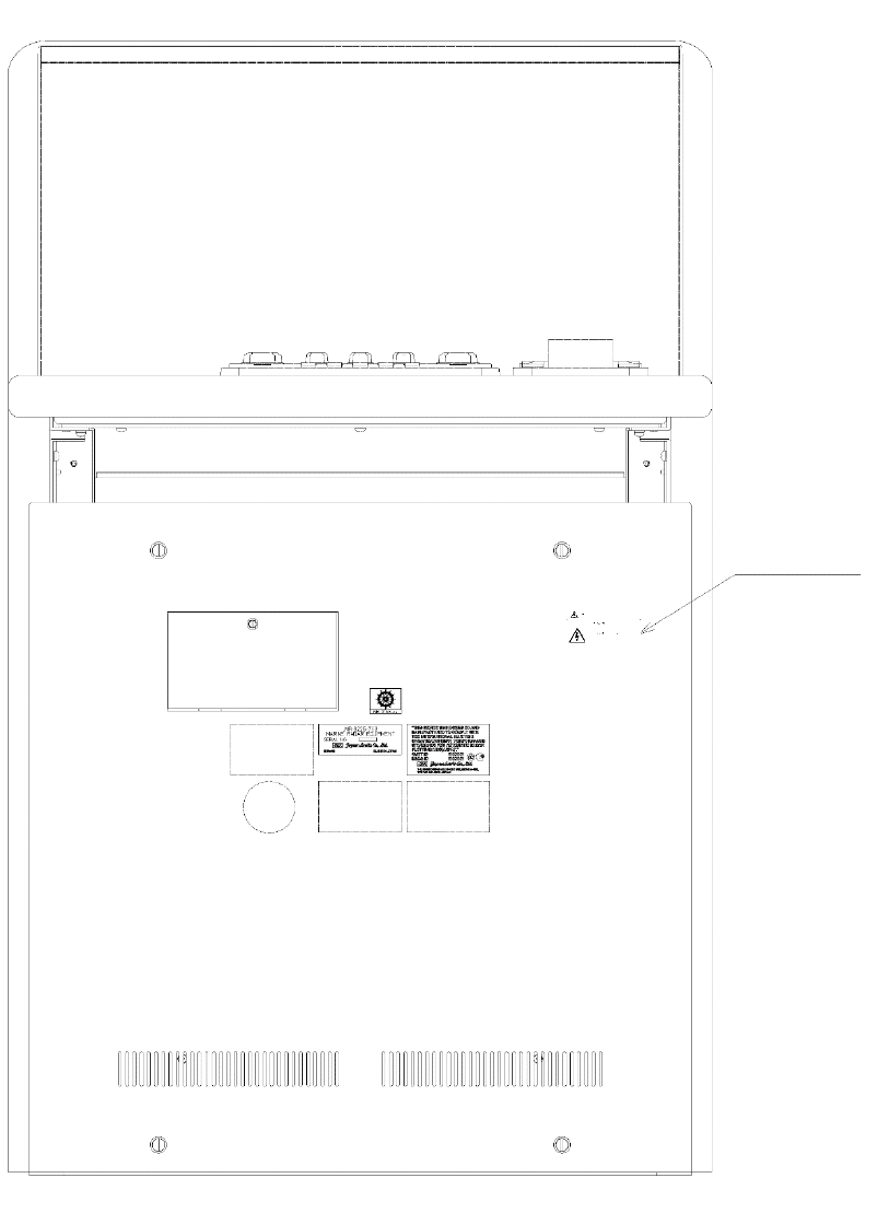
CWA-246 26inch Display Unit Mount Kit
Warning Label
xxv
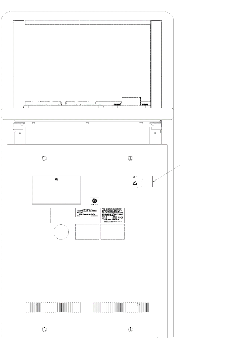
CWA-245 19inch Display Unit Mount Kit
Warning Label
xxvi
NQE-3141-4A/8A Interswitch Unit
Warning Label
xxvii
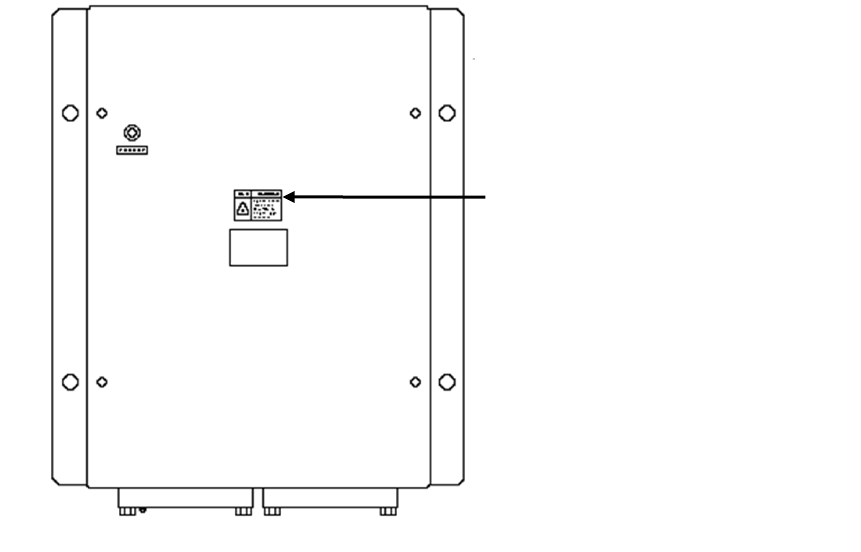
Warning Label
Warning Label
xxviii
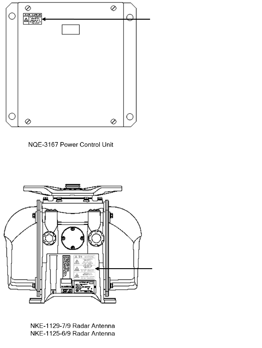
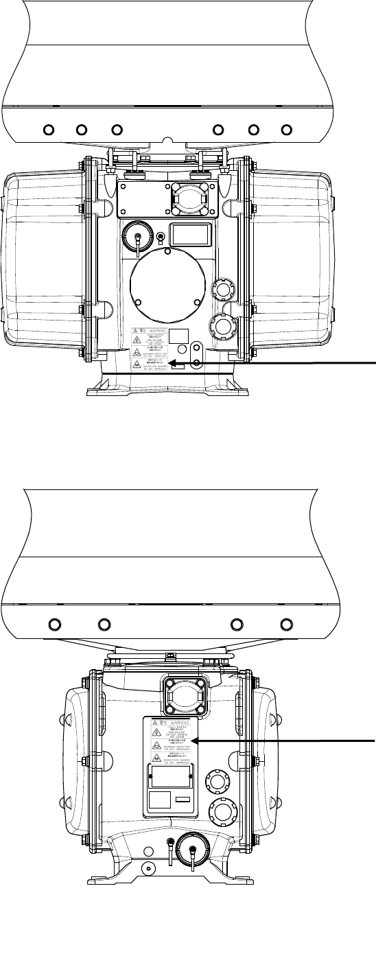
Warning Label
Warning Label
NKE-1139/1130 Radar Antenna
xxix
Warning Label
NKE-1632 Radar Antenna
Warning Label
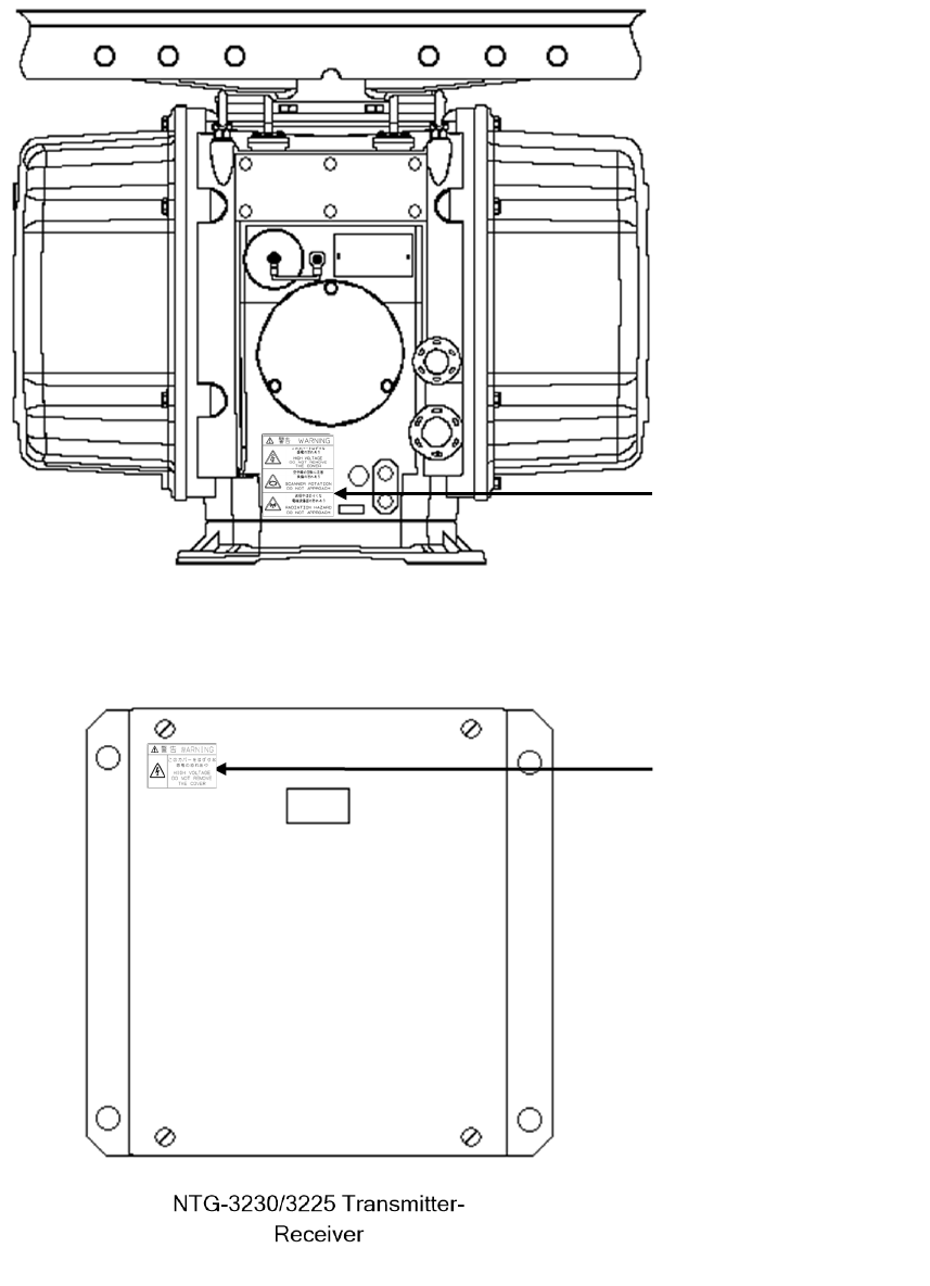
NKE-2632/2632-H Radar Antenna
xxx
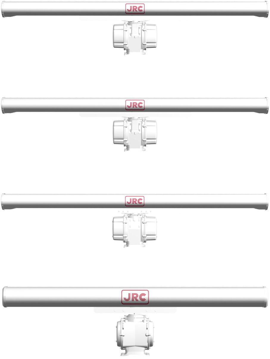
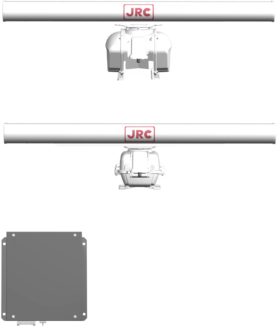
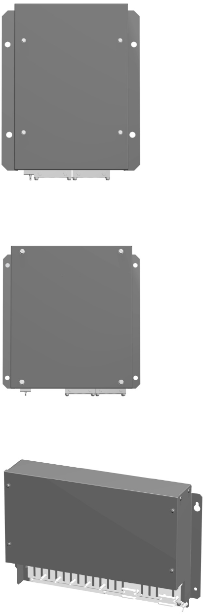
EQUIPMENT APPEARANCE
NKE-1139 Radar Antenna (12 feet)
NKE-1130 Radar Antenna (12 feet)
NKE-1632 Radar Antenna (12 feet)
NKE-2632/2632-H Radar Antenna (8 feet)

xxxi
NTG-3230 Transmitter-Receiver (30 kW)
xxxii
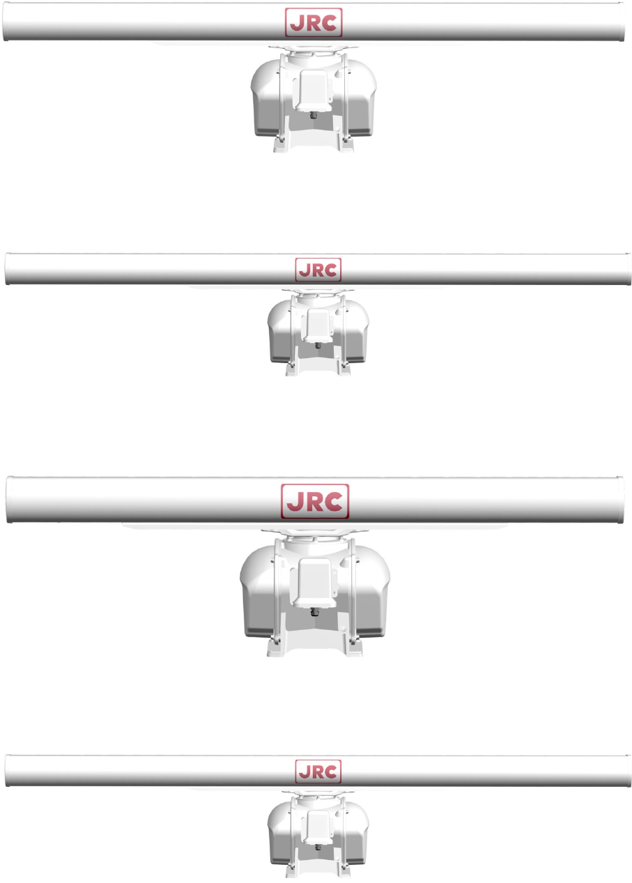
NKE-1129-7 Radar Antenna (7 feet)
NKE-1129-9 Radar Antenna (9 feet)
NKE-1125-6 Radar Antenna (6 feet)
NKE-1125-9 Radar Antenna (9 feet)
xxxiii
NKE-2254-6HS
NKE-2103/2103-6HS
NTG-3225 Transmitter-Receiver (25 kW)
xxxiv
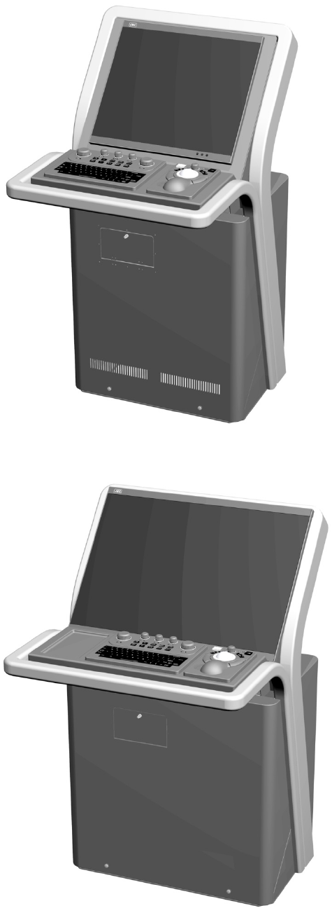
CWA-245 Display Unit
CWA-246 Display Unit
xxxv
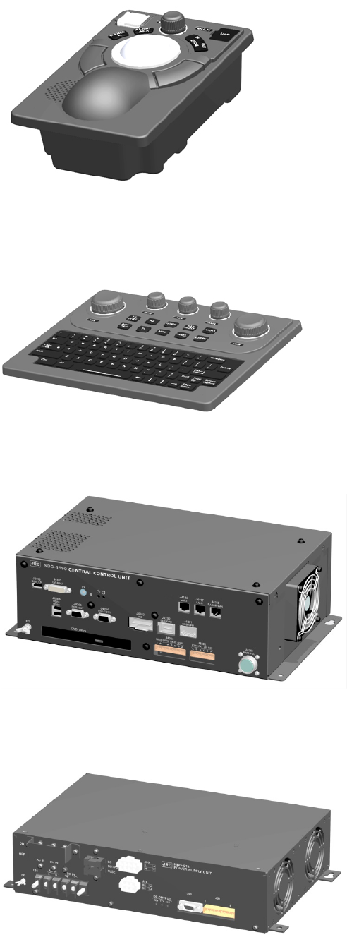
NCE-5605 Trackball Operation Unit
NCE-5625 Keyboard Operation Unit (Option)
NDC-1590 Central Processing Unit
NBD-913 Power Supply Unit
xxxvi
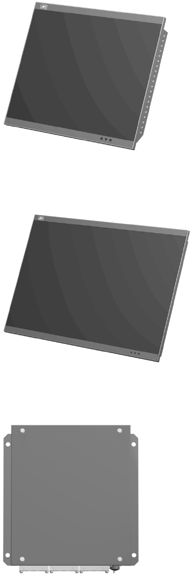
NWZ-207 19inch Display
NWZ-208 26inch Display
NQE-3167 Power Control Unit (Option)
xxxvii
NQE-3141-4A Interswitch Unit (Option)
NQE-3141-8A Interswitch Unit (Option)
NQE-1143 Junction Box
Glossary
AIO : Admiralty Information Overlay published by United Kingdom
Hydrographic Office (UKHO).
AIS : Automatic Identification System
ARCS : Admiralty Raster Chart Service. A raster chart published by UKHO
ARPA : Automatic Radar Plotting Aid
Autosail : The system automatically navigates to keep the scheduled route.
Same as automatic sailing.
AZ : Acquisition/Activation zone
Anti-clutter rain : Rain/snow clutter suppression
Anti-clutter sea : Sea clutter suppression
AZI : AZImuth stabilization mode
Base CD : Chart CD containing a complete chart data
BCR/BCT : Bow Crossing Range/Bow Crossing Time
Cell Permit : A file containing an encryption key for S-63 chart. Supplied by UKHO,
PRIMAR STAVANGER, and Hydrographic and Oceanographic
Department of Japan Coast Guard.
Chart Maintenance : Software to manage the charts. Imports and updates the charts.
C-MAP Ed.3 : C-MAP Edition 3. A digital chart format by Jeppesen (formerly, C-M A P,
Norway)
C-MAP : Digital chart data by Jeppesen (formerly, C-M A P, Norway)
CTS : Course To Steer. Heading command.
COG : Course Over the Ground
C UP : Course up. Own ship’s course is pointed to the top center of the radar
display.
CCRP : Consistent Common Reference Point. The own ship position, to which
all horizontal measurements such as target range, bearing, relative
course, relative speed, CPA or TCPA are referenced, typically the
conning position of the bridge.
CORREL : CORRELation
xxxix
CPA/TCPA : Distance to the Closest Point of Approach/Time to the Closest Point of
Approach.
CTW : Course Through Water. The direction of the ship's movement through
the water
Data Server : Organization providing S-63 chart
DIST : Distance
DR : Dead Reckoning
Dynamic License : Dynamic licensing of C-Map chart license by Jeppesen
DNV : Det Norske Veritas
DRIFT : The current velocity for manual correction or the current speed on the
horizontal axis of the 2-axis log is displayed.
EBL : Electronic Bearing Line
ECDIS : Electronic Chart Display and Information System
ENC : Electronic Navigation Chart. Meaning S-57 and S-63.
ETA : Estimated Time of Arrival
ETD : Estimated Time of Departure
ENH : Enhance
F.ETA : Final Estimated Time of Arrival. Estimated time of arrival to the last
WPT
GC : Great Circle
GPS : Global Positioning System
HDG : Heading. Ship’s heading
HL : Heading Line
HSC : High Speed Craft. Vessels which comply with the definition in SOLAS
for high speed craft
H UP : Head up. Own ship’s heading line is always pointed to the top center
of the radar display.
IHO : International Hydrographic Office
IMO : International Maritime Organization
IR : Radar Interference Rejecter
xl
ISW : InterSWitch unit
LMT : Local Mean Time
LON : Longitude
LAT : Latitude
LP : Long Pulse
MED : Marine Equipment Directive. Request standard for standardization of
marine equipment within the EU region
MFD : Abbreviation of this equipment name. The formal name is Multi
Function Display. The navigation support functions such as radar,
ECDIS, CID, and AMS with this equipment can be executed by
switching.
MMSI : Maritime Mobile Service Identity
MOB : Man Over Board
MON : Performance MOnitor
MP : Medium Pulse
NM : Nautical Mile 1 nm=1852 m
N UP : The north is always pointed to the top center of the radar display.
(North up)
P0N : Unmodulated pulse, which is a type of transmission radio wave. While
it is a type of radio wave usually used by radars equipped with
magnetrons, radio waves with a short pulse length are used also by
solid-state radars for short-range detection.
PRIMAR STAVENGER : A Norwegian company supplying charts. Publisher of encrypted charts,
S-63
PI : Parallel Index line
Past positions : Equally time-spaced past position marks of a tracked or AIS target and
the own ship.
POSN : POSitioN
PRF : Pulse Repetition Frequency. The number of radar pulses transmitted
each second.
PROC : PROCess. Radar signal processing function
Q0N : A type of radio wave with intra-pulse frequency modulation. It is used
for solid-state pulse compression radars.
xli
RL : Rhumb Line
RR : Range Rings
Relative vector : A predicted movement of a target relative to own ship’s motion
RM : Relative Motion. A display on which the position of own ship remains
fixed, and all targets move relative to own ship.
RM(R) : Relative Motion. Relative Trails
RM(T) : Relative Motion. True Trails
ROT : Rate Of Turn. Change of heading per time unit
Route : A set of waypoints
S-57 : IHO Transfer Standard for Digital Hydrographic Data
S-63 : IHO Data Protection Scheme
SA Certificate file : An electronic file certifying the supplier of S-63 chart. Required for
import/ update of S-63 chart.
SENC : System Electronic Navigational Chart
SOG : Speed Over the Ground
SART : Search And Rescue Transponder
SET : The current direction for manual correction or the current speed on the
horizontal axis of the 2-axis log is displayed.
SP : Short Pulse
STAB : STABilization
STW : Speed Through Water
TCS : Track Control Systems
TCPA : Time to Closest Point of Approach to own ship
TM : True Motion. A display across which the own ship and targets move
with their own true motions.
To WP T : To Waypoint (To WPT)
Trails : Tracks displayed by the radar echoes of targets in the form of an
afterglow
Trial maneuver : A graphical simulation facility used to assist the operator to perform a
proposed maneuver for navigation and collision avoidance purposes
xlii
True vector : A vector representing the predicted true motion of a target, as a result
of input of the course and speed of the own ship
TT : Target Tracking
TTG : Time To Go. Time to next waypoint.
TXRX : Transmitter-Receiver Unit
UKHO : United Kingdom Hydrographic Office
Update CD : Chart CD containing the chart data updated from Base CD. This can
be used when Base CD data has been imported.
USER CODE : A user-specific code assigned by JRC. Required in using ARCS and
S-63 charts.
UTC : Universal Time, Coordinated
VRM : Variable Range Marker
VDR : Voyage Data Recorder
WOL : Wheel Over Line
WOP : Wheel Over Point
WPT : Waypoint
WPT-WPT : The division of the leg specified by two points. Displays data between
two consecutive waypoints.
XTD : Cross Track Distance
XTL : Cross Track Limit
Activated target : A target representing the automatic or manual activation of a sleeping
AIS target for the display of additional information
Associated target : A target simultaneously representing a tracked target and a AIS target
which are decided as the same
Chirp : A type of transmission waveform with intra-pulse frequency
modulation used by solid-state radars. Its radio wave type is classified
as Q0N.
Clutter : Unwanted reflections on a radar screen, from sea surface, rain or
snow.
Display : Screen displayed on the LCD

xliii
Frequency deviation range : The range of variation of the Q0N frequency used for transmission
waves of a solid-state radar. Generally, the greater the frequency
deviation range, the higher the resolution in the range direction.
Hydrographic and Oceanographic Department :
Hydrographic and Oceanographic Department of Japan Coast Guard. Publisher of ENC
Import (Chart Maintenance) : A procedure of enabling the chart supplied by Base CD to be
displayed on ECDIS
Interswitch Unit : A device to switch over two or more radar display units and two or
more radar antennas
Leg : Line between two consecutive waypoints
Lost AIS target : A target symbol representing the last valid position of an AIS target
before the reception of its data was lost, or its last dead-reckoned
position.
Lost tracked target : One for which target information is no longer available due to poor, lost
or obscured signals.
Power amplifier : A radio frequency amplifier circuit consisting of semiconductor
elements used for solid-state radars. It employs a high frequency, high
power FET.
Primary : Main positioning sensor
Pulse compression : Correlation processing performed when a transmitted chirp signal is
received by a solid-state radar after reflecting off the target. This
processing gain enables the radar to have necessary detection
capability even when a transmission power is low.
Radar beacon : A navigation aid which responds to the radar transmission and
generates radio wave
Range : An area of the chart displayed on the screen. Represented by one half
of the length of the chart display screen.
Range side lobe : False image that is generated as a result of pulse compression
processing in the solid-state radar when there is a large target such as
a large ship in the vicinity.
Reference target : A fixed target specified to calculate the speed over the ground
Report : User report to be issued periodically for using the Dynamic License
method of Jeppesen continuously
Rubber band : Border that indicates the selected range.
Scale : The display scale
xliv
Sea state : The average height of the wave expressed by dividing into several
classes.
Ship-avoiding operation : To operate the ship in order to avoid obstacles during automatic
navigation, regardless of the scheduled route
Sleeping AIS target : A target indicating the presence and orientation of a vessel equipped
with AIS
Spot depth : Numeric representation of depth
SSR: Solid State Radar : Radar that uses semiconductor elements instead of magnetron, which
requires periodic replacement. It is built with a system that ensures
necessary detection capability even when a transmission output is low,
by using chirp signals with a long pulse length upon transmission and
performing pulse compression upon reception
Update (Chart Maintenance) : A procedure of reflecting the update data supplied by Update CD on
the imported chart.

xlv
How to Use This Manual
Structure of this manual
This manual is structured as shown below. Read the necessary section according to the purpose.
Item Contents
Preface Describes the purposes of using this equipment.
Safety Cautions
Emergency Measures
Describes the cautions for a high voltage, precautions
for rescue of victims of an electric shock, and the
method of First-Aid treatment.
Pictorial Indication
Precautions Upon Equipment Operation
Describes the safety precautions and warning on this
equipment.
The Mounting Point of the Warning
Label
Describes the warning label attachment position on
this equipment.
Equipment Appearance Describes the appearance of this equipment.
Glossary Describes the special terminologies and
equipment-specific terminologies that are used in this
manual.
How to use this manual This page
<Basic Operation >
Section 1 Overview Describes the overview of this equipment.
Section 2
Name and Function of Each Unit
Describes the name and function of each unit of this
equipment.
Section 3
Common Basic Operations
Describes the common basic operations of RADAR
and ECDIS.
Section 4
Range and Bearing Measurement
Methods
Describes the measuring methods of range and
bearing using the measuring tools.
<Function>
Section 5
Basic Operation of the Radar
Describes the basic RADAR operations.
Section 6
Target Tracking and AIS
Describes the methods of using target tracking and
AIS.
Section 7
True and False Echoes on Display
Describes how to check the radar screen.
Section 8
Functions of the ECDIS (Option)
Describes the basic ECDIS operations.
Section 9
Route Planning
Describes route planning.
Section 10
Route Monitoring
Describes route monitoring.
Section 11
Monitoring a Dragging Anchor
Describes anchor monitoring.

xlvi
<Function>
Section 12
Automatic Sailing (Option)
Describes automatic sailing.
Section 13
Operating a Chart (Option)
Describes chart operations.
Section 14
Creating a User Map/ Updating a Chart
Describes creation of user maps and automatic chart
updating.
Section 15
Logbook
Describes the logbook.
Section 16
Setting Up Screen View
Describes the detail setting of screen display.
<Reference>
Section 17
Setting Up Alerts
Describes the alert detail setting for avoiding dangers.
Section 18
Setting Up the Operation Mode
Describes the detail setting of the operation modes of
this equipment.
Section 19
Adjusting and Setting Up Equipment (for
Services)
Describes the equipment adjustments and setting that
are performed by the maintenance engineers.
Section 20
Playing Back Data Recorded During
Navigation [Playback]
Describes playback of the data recorded during
sailing.
Section 21
Maintenance & Inspection
Describes the maintenance and inspection of this
equipment.
Section 22
Failures and After-Sale Services
Describes the failure handling measures and
aftercare services of this equipment.
Section 23
About Disposal
Describes the cautions on disposing of this
equipment.
Section 24
Specifications
Describes the specification of this equipment.
Appendix A
Radar Antenna Block Diagrams
Describes various block diagrams, connection
diagrams, schematic diagrams, and setting tables.
Appendix B
Alert List
Describes the alert list.
Appendix C
Setting the Interswitch
Describes the interswitch setting.
Appendix D
Menu List and Materials
Describes the materials such as the menu list.

xlvii
Notations
Operation notations
Trackball operations on the operation panel are expressed as follows.
Operation Notation
Click the left button. Click
Example: Click on the object.
Double-click the left button. Double-click
Example: Determine the drawing by double-click.
Click the right button Click the right mouse button
Example: Display the context menu by clicking the right mouse
button.
The buttons and dialog boxes on the screen are expressed as follows.
Button type Notation
Button with button name indicated Example: → [AUTO] (automatic) button
Button with an indication other than the
button name such as an icon
Shown as follows.
Example: → Task switching button
A series menu selection operations is expressed as follows.
Click on [User Map] - [Information Mark Property] - [Position] on the menu.
Touch panel operation
In this manual, the use of a trackball is applied as the precondition of the operation explanation.
When the optional touch panel is used, read the notations in this manual as follows.
Trackball operation Touch panel operation
(Left) click Single tap
Double-click Double tap
Right click Long tap
For the operations that can be executed by touch panel operations, refer to the section "3.20
Touch Panel (Option)".
xlviii

(1) Contents
2
3
4
5
6
7
8
9
10
11
12
13
14
15
16
17
18
19
20
21
22
23
24
25
26
27
Contents
Basic Operation
Section 1 Overview ........................................................................................ 1-1
1.1 Functions ............................................................................................................................... 1-2
1.2 Features ................................................................................................................................ 1-5
1.3 Components .......................................................................................................................... 1-8
1.4 Structure .............................................................................................................................. 1-13
1.5 General System Diagrams .................................................................................................. 1-42
Section 2 Name and Function of Each Unit ................................................. 2-1
2.1 Name and Main Function of the Operation Unit ................................................................... 2-1
2.1.1 Trackball operation unit ................................................................................................. 2-1
2.1.2 Keyboard operation unit (Option) .................................................................................. 2-2
2.1.3 Display unit ................................................................................................................... 2-4
2.2 Names and Main Functions of the Task Screen Common Sections ..................................... 2-5
2.2.1 Right Toolbar ................................................................................................................. 2-6
2.2.2 Left Toolbar ................................................................................................................... 2-7
2.2.2.1 Buttons that are normally displayed ....................................................................... 2-8
2.2.2.2 Buttons that are normally hidden ............................................................................ 2-9
2.2.3 Alert notification area .................................................................................................... 2-9
2.2.4 Key assignment indication area .................................................................................. 2-10
2.2.5 Navigation tools .......................................................................................................... 2-10
2.2.6 Own Ship Information ................................................................................................. 2-11
2.3 Common Information Window ............................................................................................. 2-14
2.3.1 Information monitor windows ...................................................................................... 2-15
2.3.1.1 Target INFO .......................................................................................................... 2-16
2.3.1.2 TT List ................................................................................................................... 2-20
2.3.1.3 AIS List ................................................................................................................. 2-20
2.3.1.4 AIS Detail INFO .................................................................................................... 2-21
2.3.1.5 2nd PPI ................................................................................................................. 2-24
2.3.1.6 Wave Analysis (option) ......................................................................................... 2-26
2.3.1.7 Current/Wind Block ............................................................................................... 2-34
2.3.1.8 Conning ................................................................................................................ 2-38
2.3.2 Information reference windows ................................................................................... 2-40
2.3.2.1 Switching between a standard window and an extended window ....................... 2-41
2.3.2.2 AIS MSG Tray ....................................................................................................... 2-43
2.3.2.3 NAVTEX ................................................................................................................ 2-44
2.3.2.4 Active Alert ............................................................................................................ 2-46
2.3.2.5 Alert History .......................................................................................................... 2-47

Contents (2)
2.3.2.6 AIS ........................................................................................................................ 2-48
2.4 Names and Main Functions of Each Section of the RADAR Screen .................................. 2-50
2.4.1 Presentation and mode information ............................................................................ 2-51
2.4.2 Radar signal information ............................................................................................. 2-52
2.4.3 Radar system information ........................................................................................... 2-53
2.4.4 Own track information ................................................................................................. 2-54
2.4.5 Other ship information................................................................................................. 2-55
2.4.6 Display inside the PPI ................................................................................................. 2-56
2.5 Names and Main Functions of Each Section of the ECDIS Screen (Option) ..................... 2-57
2.5.1 Chart Information Area (ENC/C-MAP) ........................................................................ 2-58
2.5.2 Chart Information Area (RNC) .................................................................................... 2-60
2.5.3 Sub Information Area .................................................................................................. 2-61
2.5.4 ARCS PIN input dialog box ......................................................................................... 2-64
Section 3
Common Basic Operations
........................................................................ 3-1
3.1 Powering On and Starting ..................................................................................................... 3-1
3.2 Starting Each Mode ............................................................................................................... 3-3
3.3 Basic Operations when using a Trackball ............................................................................. 3-5
3.3.1 Basic trackball operations ............................................................................................. 3-5
3.3.2 Basic click operations ................................................................................................... 3-5
3.3.2.1 Selecting a button ................................................................................................... 3-5
3.3.2.2 Selecting a single object ......................................................................................... 3-5
3.3.2.3 Selecting multiple objects ....................................................................................... 3-6
3.3.3 Basic operations of double-clicking .............................................................................. 3-6
3.3.4 Basic operations of clicking the right button ................................................................. 3-6
3.3.5 Displaying simplified information and operational guide of objects .............................. 3-7
3.3.6 Cursor types .................................................................................................................. 3-8
3.4 Basic Menu Operations ....................................................................................................... 3-10
3.4.1 Opening the menu ...................................................................................................... 3-10
3.4.2 Menu list ...................................................................................................................... 3-14
3.4.3 Closing the menu ........................................................................................................ 3-14
3.5 Basic Dialog Box Operations .............................................................................................. 3-15
3.5.1 Changing dialog box settings ...................................................................................... 3-15
3.5.2 Closing a dialog box.................................................................................................... 3-16
3.5.3 Title Bar ....................................................................................................................... 3-17
3.6 Operation of the Information Monitor Window .................................................................... 3-18
3.6.1 Opening the information monitor window ................................................................... 3-18
3.6.2 Displaying an information monitor window from other than the "Page Selection"
dialog box .................................................................................................................... 3-21
3.7 Confirming and Acknowledging an Alert ............................................................................. 3-22
3.7.1 Stopping a buzzer ....................................................................................................... 3-23
3.7.2 Confirming alert contents ............................................................................................ 3-23
3.7.3 Acknowledging the alert .............................................................................................. 3-26

(3) Contents
2
3
4
5
6
7
8
9
10
11
12
13
14
15
16
17
18
19
20
21
22
23
24
25
26
27
3.7.4 Displaying alert list and alert history ........................................................................... 3-27
3.8 Switching the Day/Night Mode ............................................................................................ 3-32
3.9 Adjusting the Brightness of the Screen and Operation Unit ............................................... 3-34
3.10 MOB (Man Over Board) ...................................................................................................... 3-36
3.11 Electronic Bearing Line (EBL) and Variable Range Marker (VRM) .................................... 3-39
3.11.1 Electronic Bearing Line (EBL) and Variable range marker (VRM) ............................. 3-39
3.11.2 Displaying the EBL and VRM buttons ......................................................................... 3-40
3.11.2.1 RADAR ................................................................................................................. 3-40
3.11.2.2 ECDIS ................................................................................................................... 3-41
3.11.3 Basic manipulation of EBL/VRM ................................................................................. 3-42
3.11.3.1 Switching the control right of EBL/VRM ............................................................... 3-42
3.11.3.2 Setting up the measurement starting points ......................................................... 3-43
3.11.3.3 Setting the EBL bearing to True/Relative display ................................................. 3-44
3.11.3.4 Setting up the range unit of VRM ......................................................................... 3-44
3.11.3.5 Operating the intersecting point between EBL and VRM ..................................... 3-45
3.12 Cursor AUTO Mode ............................................................................................................. 3-46
3.12.1 No object ..................................................................................................................... 3-47
3.12.2 AIS .............................................................................................................................. 3-47
3.12.3 TT ................................................................................................................................ 3-48
3.12.4 (AZ) Acquisition/Activation Zone ................................................................................. 3-49
3.12.5 AIS filter ...................................................................................................................... 3-50
3.12.6 User map .................................................................................................................... 3-50
3.12.6.1 Non-selected object .............................................................................................. 3-50
3.12.6.2 Selected object ..................................................................................................... 3-51
3.12.7 Mariner's Mark/Line .................................................................................................... 3-55
3.12.7.1 Object in the non-selected state ........................................................................... 3-55
3.12.7.2 Object in selected state ........................................................................................ 3-55
3.12.8 Manual updating ......................................................................................................... 3-57
3.12.8.1 Unsaved object ..................................................................................................... 3-57
3.12.8.2 Saved object ......................................................................................................... 3-57
3.12.9 Buoy object ................................................................................................................. 3-57
3.12.10 Light object .................................................................................................................. 3-57
3.12.11 EBL ............................................................................................................................. 3-57
3.12.12 VRM ............................................................................................................................ 3-57
3.12.13 EBL/VRM intersecting point ........................................................................................ 3-58
3.12.14 Node Fixed EBL/VRM ................................................................................................. 3-58
3.12.15 PI ................................................................................................................................. 3-58
3.12.16 WPT of monitored route .............................................................................................. 3-58
3.12.17 Monitoring dragging anchor ........................................................................................ 3-58
3.12.17.1 Object in the unselected state .......................................................................... 3-58
3.12.17.2 Selected state ................................................................................................... 3-58
3.12.18 Planned route .............................................................................................................. 3-59

Contents (4)
3.13 Saving the screen that is currently displayed...................................................................... 3-61
3.14 [MULTI] Dial ......................................................................................................................... 3-62
3.14.1 Functions of [MULTI] dial ............................................................................................ 3-62
3.14.2 Functions assigned to [MULTI] dial ............................................................................. 3-62
3.14.2.1 Displaying a screen for setting the function that is assigned ............................... 3-62
3.14.2.2 Changing the function that is assigned ................................................................ 3-62
3.15 Basic Operations of the Software Keyboard ....................................................................... 3-64
3.15.1 Starting a software keyboard ...................................................................................... 3-64
3.15.2 Name and function of each section of the keyboard .................................................. 3-65
3.15.3 Numeric value input example ..................................................................................... 3-68
3.15.4 Character input example ............................................................................................. 3-70
3.16 Setting a Date and a Time (Calendar Operation) ............................................................... 3-73
3.16.1 Details and usage of a calendar picker and a time picker .......................................... 3-74
3.16.1.1 Details of a calendar ............................................................................................. 3-74
3.16.1.2 How to use a calendar .......................................................................................... 3-75
3.17 Help ..................................................................................................................................... 3-76
3.18 Password Input ................................................................................................................... 3-80
3.19 Managing Files with File Manager ...................................................................................... 3-82
3.19.1 Displaying the "File Manager" dialog box ................................................................... 3-82
3.19.2 File management ........................................................................................................ 3-83
3.19.3 Loading and saving files ............................................................................................. 3-86
3.19.3.1 Loading files ......................................................................................................... 3-86
3.19.3.2 Unloading data (clearing data from the data screen) ........................................... 3-88
3.19.3.3 Saving files ........................................................................................................... 3-89
3.20 Touch Panel (Option) .......................................................................................................... 3-90
3.21 Returning to a Task Menu by Ending the Operation ........................................................... 3-91
3.22 Terminating this equipment ................................................................................................. 3-93
3.23 Using a DVD Drive .............................................................................................................. 3-94
Section 4 Range and Bearing Measurement Methods ................................ 4-1
4.1 List of Measuring Tools ......................................................................................................... 4-1
4.2 Target Position ...................................................................................................................... 4-2
4.3 Using the Cross-hair Cursor.................................................................................................. 4-3
4.3.1 Cursor readout information area display position ......................................................... 4-3
4.3.1.1 RADAR ................................................................................................................... 4-3
4.3.1.2 ECDIS ..................................................................................................................... 4-4
4.3.2 Measuring the bearing and the range from the own ship’s position to the target by
using the cross-hair cursor ........................................................................................... 4-5
4.3.2.1 Measuring by using the cursor information that is displayed by placing the
cursor inside of PPI (RADAR only) ......................................................................... 4-5
4.3.2.2 Measuring by using the "Cursor readout" dialog .................................................... 4-6
4.3.2.3 Switching the cursor bearing between True/Relative ............................................. 4-7

(5) Contents
2
3
4
5
6
7
8
9
10
11
12
13
14
15
16
17
18
19
20
21
22
23
24
25
26
27
4.3.2.4 Switching the cursor range unit .............................................................................. 4-7
4.4 Using the Range Rings ......................................................................................................... 4-8
4.5 Using the Electronic Bearing Line (EBL) and Variable Range Marker (VRM) .................... 4-10
4.5.1 Measuring a range and a bearing with EBL and VRM ............................................... 4-10
4.5.1.1 Measuring in the trackball operation unit .............................................................. 4-10
4.5.1.2 Measuring with the [EBL] or [VRM] dial on the keyboard operation unit .............. 4-11
4.5.2 Measuring between arbitrary two points ..................................................................... 4-14
4.5.3 Manipulating EBL/VRM with the context menu (ECDIS only) .................................... 4-16
4.5.3.1 Manipulating EBL/VRM with [Dropped EBL/VRM] - [Make EBL1/VRM1] or
[Make EBL2/VRM2] .............................................................................................. 4-17
4.5.3.2 Manipulating EBL with [Dropped EBL/VRM] - [Make EBL1] or [Make EBL2] ...... 4-18
4.5.3.3 Manipulating VRM with [Dropped EBL/VRM] - [Make VRM1] or [Make VRM2] ... 4-19
4.5.3.4 Manipulating EBL/VRM with [Dropped EBL/VRM] - [Move base point of
EBL1/VRM1] or [Move base point of EBL2/VRM2] .............................................. 4-19
4.5.3.5 Manipulating EBL/VRM with [CCRP EBL/VRM] - [Make EBL1/VRM1] or
[Make EBL2/VRM2] .............................................................................................. 4-20
4.5.3.6 Manipulating EBL with [CCRP EBL/VRM] - [Make EBL1] or [Make EBL2] .......... 4-21
4.5.3.7 Manipulating VRM with [CCRP EBL/VRM] - [Make VRM1] or [Make VRM2] ...... 4-21
4.6 Using Parallel Index Lines (PI) ............................................................................................ 4-22
4.6.1 Description of a parallel index line .............................................................................. 4-22
4.6.2 Displaying parallel index lines ..................................................................................... 4-22
4.6.2.1 Displaying parallel index lines in the trackball operation unit ............................... 4-22
4.6.2.2 Displaying parallel index lines in the keyboard operation unit .............................. 4-23
4.6.2.3 Description of the "PI Menu" dialog ...................................................................... 4-24
4.6.3 Setting all the parallel index lines concurrently (All mode) ......................................... 4-28
4.6.3.1 Changing the bearing/interval of parallel index lines in the trackball operation
unit (All mode) ...................................................................................................... 4-30
4.6.4 Setting parallel index lines individually (Individual mode) ........................................... 4-31
4.6.4.1 Changing the bearing/interval/end point of parallel index lines in the trackball
operation unit (Individual mode) ........................................................................... 4-34
4.6.5 Displaying lines at equal interval on the left and right sides of the own ship’s
position (Track mode) ................................................................................................. 4-35
4.6.5.1 Changing the bearing/interval of parallel index lines with the trackball (Track
mode) .................................................................................................................... 4-37
4.6.6 Displaying two intersecting lines (Equiangular mode) ................................................ 4-38
4.6.6.1 Changing the bearing of two intersecting lines in the trackball operation unit
(Equiangular mode) .............................................................................................. 4-39
4.6.7 Setting parallel index lines in the keyboard operation unit ......................................... 4-40
4.6.7.1 Operation in All mode ........................................................................................... 4-40
4.6.7.2 Operation in Individual mode ................................................................................ 4-41
4.6.7.3 Operation in Track mode ...................................................................................... 4-41
4.6.7.4 Operation in Equiangular mode ............................................................................ 4-42
4.7 Using the EBL Maneuver .................................................................................................... 4-43

Contents (6)
4.7.1 Displaying the EBL Maneuver Setting dialog box ....................................................... 4-43
4.7.2 Clearing the display of maneuver curve ..................................................................... 4-44
4.7.3 Setting the creation conditions of the EBL Maneuver ................................................. 4-44
4.7.4 Creating an EBL maneuver curve ............................................................................... 4-45
4.8 Connecting Own Ship and the Specified Fixed Position with EBL and the VRM Marker (Node
Fixed EBL/VRM Function) ................................................................................................... 4-47
4.8.1 Displaying the "Node Fixed EBL/VRM" dialog box ..................................................... 4-47
4.8.2 Description of "Node Fixed EBL/VRM" dialog box ..................................................... 4-48
4.8.3 Creating a new Node Fixed EBL/VRM ....................................................................... 4-48
4.8.4 Cancelling the Node Fixed EBL/VRM function ........................................................... 4-49
4.9 Measuring the Own Ship’s Position Manually (LOPs Fixing Function of Manual position fix)4-50
4.9.1 Displaying the "Manual position fix" dialog box .......................................................... 4-50
4.9.2 Description of the "LOPs Fixing" tab of the "Manual position fix" dialog box ............. 4-51
4.9.3 Creating LOP .............................................................................................................. 4-53
4.9.3.1 Creating bearing LOP ........................................................................................... 4-53
4.9.3.2 Creating distance LOP ......................................................................................... 4-55
4.9.4 Measuring the own ship’s position in cross bearing fix ............................................... 4-56
4.9.4.1 Automatic position fixing ....................................................................................... 4-57
4.9.4.2 Automatic offset .................................................................................................... 4-58
4.9.4.3 Manual position fixing ........................................................................................... 4-60
4.9.4.4 When there are three or more LOPs or TPLs ...................................................... 4-61
4.9.4.5 Setting a plotted position ...................................................................................... 4-63
4.9.5 Measuring the own ship’s position with Running Fix .................................................. 4-64
4.9.6 Measuring the own ship’s position with other methods .............................................. 4-68
4.10 Offsetting the Own Ship’s Position Manually (Position Offset Function of Manual position fix)4-69
4.10.1 Displaying the "Manual position fix" dialog box .......................................................... 4-69
4.10.2 Description of the [Position Offset] tab of the "Manual position fix" dialog box .......... 4-71
4.10.3 Setting the offset amount that is input in the "Enter Offset" dialog as the offset
position ........................................................................................................................ 4-72
4.10.4 Setting the position on the chart on which the mouse button was clicked as the
offset position .............................................................................................................. 4-73
4.10.5 Recording LOPs Fixing operation in the logbook ....................................................... 4-74
4.10.6 Offsetting the own ship position .................................................................................. 4-76
1-1 Section 1 Overview
1
2
3
4
5
6
7
8
9
10
11
12
13
14
15
16
17
18
19
20
21
22
23
24
25
26
27
付録
Section 1 Overview
Do not put any container with water or small metallic object on this equipment.
Water may spill or metal may enter the equipment, causing fire, electric shock or
other troubles.
Should water or metal have entered the equipment, turn off the circuit breaker and
contact our sales division, branch office, service center or representative located
nearest to you.
If you continue to use the equipment without taking required
action, fire, electric
shock or other troubles may occur.
Should you find out smoke, offensive smell or extreme heat on the equipment, turn off
the switch and circuit breaker immediately. Then contact our sales division, branch
office, service center or representative located nearest to you.
If you continue to use the equipment without taking required action, fire or electric
shock may occur.
Do not use or leave the equipment where there is a direct sunshine and high humidity
or the temperature exceeds 55°C.
Otherwise, fire or other troubles may occur.
Do not block the ventilation port of the equipment.
Otherwise, fire or other troubles may be caused by heat accumulation.
Use this equipment as your navigation aid.
• If you install two ECDIS's
without backup system, be sure to use the specified
marine chart for your navigational decision.
• This equipment does not provide automatic decision on the positional information.
Decision on the positional information must be made by the ship operator himself.
A trouble will occur if checkup is neglected.
Do not touch the equipment when your
hands or gloves are wet with fresh water or
seawater.
Otherwise, electric shock or other troubles may occur.
Section 1 Overview 1-2
• When there is an alarm of fan failure or CPU
temperature rise, turn off the power
immediately.
If you continue to use the equipment without taking required action, fire or other
troubles may occur.
Contact our sales division, branch office, service center or representative located
nearest to you.
1.1 Functions
Marine radar equipment (referred to as "this equipment" in this manual) is navigation equipment that
satisfies the following IMO performance standards.
• IMO Resolution MSC192(79): Performance standards for radar equipment
• IMO Resolution MSC232(82): Performance standards for electronic chart display and information
systems (ECDIS)*1
• IMO Resolution MSC191(79): Performance standards for the presentation of navigation related
information on shipborne navigational displays
• IMO Resolution MSC74(69): Annex 2: TCS*2 performance standards
• IMO Resolution A.694(17): General requirements for shipborne radio equipment
• IMO Resolution MSC302(87): Bridge Alert Management
*1: Case where the ECDIS function is added as the option
*2: Case where the TCS function is added as the option
Any of the following task functions can be added to this equipment as the option, enabling the
equipment to be used as a multi-function display.
• ECDIS
• Conning Display
Main functions of the RADAR mode
• Sensitivity adjustment, sea clutter and rain/snow clutter suppression
• Interference rejection
• Bearing and range measurement using a cursor, fixed/variable range markers, and electronic
bearing line
• Colored own track display
• User map creation and display
• TM (True Motion) presentation
• Self-diagnostic facilities
• Radar performance monitoring (Performance Monitor)
• Target tracking functions (manual/automatic target acquisition and tracking, vector and trail displays
and alarm displays)
• 8-unit switchover (Interswitch) function (Option)
• Electronic navigational chart display*1 (Option)
*1: The following databases can be displayed (ARCS cannot be displayed.)

1-3 Section 1 Overview
1
2
3
4
5
6
7
8
9
10
11
12
13
14
15
16
17
18
19
20
21
22
23
24
25
26
27
付録
- S-57 Ed3.0/3.1
- S-63
- C-Map Ed3.0 Professional/Professional+
- C-Map ENC
- Jeppesen PRIMAR ECDIS Service
Main functions of the ECDIS mode
• The following databases can be displayed.
- S-57 Ed3.0/3.1
- S-63
- C-Map Ed3.0 Professional/Professional+
- C-Map ENC
- Jeppesen PRIMAR ECDIS Service
- ARCS
• Own ship’s track display and planned-route display on the electronic chart
• Automatic checking of the safety contours and dangerous areas of the own ship (not available for
ARCS)
• TT target display and AIS target display on the electronic chart
• Overlay of radar echo on the electronic chart
• True/Relative motion display
• North-up/Course-up/Head-up/Waypoint-up display
• Display of route information such as latitude/longitude at destinations, bearings/ranges up to
waypoints, and planned arrival time
• Availability of two EBLs/VRMs
• Writing of memos with alphabetic characters into the electronic chart
• Display of information such as the date/time, current position, heading, and ship’s speed
• Selection of colors (conforming to the IMO/IHO) suitable for the daytime, nighttime, dawn and
evening
• Editing of route information
Addition, deletion, and modification of WPTs on the electronic chart or the list
Calculation of the distance between WPTs, bearings, and planned arrival time
Up to 512 WPTs per route
Checking on the crossing of the safety contours and dangerous areas on created routes
• Route tracking (option)
• Course change
• Safety contours crossing alarm
• Dangerous areas approaching warning
• Waypoint arrival warning
• Off-track warning
• Logging of navigation information onto the SSD
• Own ship’s playback using logged data

Section 1 Overview 1-4
Note
This manual describes the methods of handling the RADAR mode and the ECDIS mode, however,
this manual does not describe the handling method of the Conning mode. For the handling of the
conning mode, refer to the “JAN-7202/9202 Conning Display Instruction Manual”.

1-5 Section 1 Overview
1
2
3
4
5
6
7
8
9
10
11
12
13
14
15
16
17
18
19
20
21
22
23
24
25
26
27
付録
1.2 Features
This MFD has the following features:
Common functions:
Utilization of an icon menu
Intuitive operation system based on the workflow
High-resolution large screen
Message reception notification function
Notifies arrival of a new AIS message and so on with a sound and a badge.
Utilization of a common information window
Enables display of target information and simple conning information (wind direction/wind speed
information, etc.) with a simple switching operation.
Display of chart information read results by grouping
Enables immediate access to the required information.
Display of the cause of alert as well as the action guideline
Equipped with the Help function
The built-in HTML Help enables the search of operation methods in this equipment instead of the
hardcopy manual whenever required.
Visual highlight of target symbols
Enables identification of the target that matches the condition such as the sailing direction, ship’s
length, and ship’s type by highlighted display.
Wave analysis function (option)
Analyzes and displays information on the surrounding waves (height, length, cycle, and direction
of waves) and enables monitoring of dangerous waves for ships.
Equipped with the white list type virus protection function of Trend Micro Incorporated
RADAR function:
Realized a clear large screen with its high resolution.
By using the high definition 26inch color LCD of 1920×1200 pixels, radar image display of
diameter 320mm or more is secured. Image presentation of high resolution is also possible in
near ranges.

Section 1 Overview 1-6
Equipped with high performance radar signal processing ASIC BLZZARD™ of new design
By eliminating unnecessary signals (clutters) from the radar video signals obtained from a wide
dynamic range receiver, target detection is enhanced.
Target tracking (TT) function by utilizing the latest technology
By using the latest high-speed DSP and tracking algorithm, the target acquisition/tracking
performance is improved, achieving stable operation for target tracking inside of clutters also.
- Acquisition and tracking of up to 100 targets as standard
- Expressing danger status with a sound and shape and color of a symbol
- Equipped with a trial maneuvering function
- Capable of 10-color coded display by storing target trails.
Background tracking function (Full-screen acquisition function)
Since detectable radar echoes are acquired and tracked automatically in background, the vector
can be displayed immediately after initial acquisition.
Top screen with strictly selected information
Information that is constantly displayed on the Top screen of the radar is strictly selected to enable
users to find the required information effortlessly.
Sortable TT/AIS list
Provides a sortable TT/AIS list (for instance in the TCPA descending order) to enable users to
check the ship in the highest danger.
Dual PPI display
Capable of monitoring of near-range images and far-range images concurrently with one radar
(JMR-9200 Series only).
Superimposed display of radar image, chart, and own ship’s trail
Capable of superimposed display of a user-created map, an imported chart of a coastline and
buoys, own ship’s trail, and other ship’s trails, radar images, and radar trails in all the display
modes including Head Up display.
Improved Day/Night function
The Day/Night function supports up to 5 types of display screen color combinations and enables
users to reproduce screen colors suitable for the user utilization environment with simple key
operations. The function provides easy-to-understand screens through color coded radar images
and a variety of graphics.
Built-in self-diagnosis program
By constantly monitoring all the system functions, this program displays a warning message on
the screen at detection of function deterioration and issues a warning sound. The system function
test can be performed easily during normal operation (excluding some tests).

1-7 Section 1 Overview
1
2
3
4
5
6
7
8
9
10
11
12
13
14
15
16
17
18
19
20
21
22
23
24
25
26
27
付録
Performance monitor function
This function monitors radar performance (transmission output and reception sensitivity) on the
screen.
Interswitch function (Option)
By connecting to the interswitch unit (optional), up to 8 radars can be inter-switched with simple
operations.
Up to 4 units: An interswitch unit separate type from the indicator and cable for connecting each
indicator are necessary.
Up to 8 units: An interswitch unit separate type from the indicator and cable for connecting each
indicator are necessary.
ECDIS function:
This function minimizes the information that is displayed constantly and expands the chart
display area.
- Can display vector charts (ENC and C-MAP) and raster chart (ARCS).
- Realizes safer sailing through the safety contour line and crossing and approaching danger
zone monitoring function. (Excluding ARCS)
- Realizes high operability through high-speed drawing and high-speed processing.
- Facilitates creation of user charts.
- Applies a multi-display screen that can display two charts concurrently. (ARCS and C-MAP
Ed.3 cannot be displayed concurrently with a chart of a different type)
- Enables a course plan with multi-view.
- Can display a wide view screen while a single chart or multi-view is displayed.
- Enables creation of a route plan with the table editing function and the graphic editing function.
- Can create an alternative route while sailing.
- Automatic sailing is enabled by connecting with Auto Pilot. (option)
- The playback function enables checking of the sailed routes.
- The S-57 chart can be updated. (Chart Maintenance)

Section 1 Overview 1-8
1.3 Components
A list of components and optional accessories is shown below.
Components of the Display Unit
Name Model Q'ty Remarks
Display unit
Main unit
Display
(JMR-72XX/JAN-72XX)
NWZ-207
1 Included in the main unit.
(JMR-92XX/JAN-92XX)
NWZ-208
Trackball operation unit NCE-5605 1 Included in the main unit.
Keyboard operation unit NCE-5625 1 Option
Central processing unit NDC-1590 1 Included in the main unit.
Power supply unit NBD-913 1 Included in the main unit.
Junction box NQE-1143 1 Included in the main unit.
Serial LAN I/F Interface
circuit
CMH-2370 1 Option
Analog Option circuit CMJ-560 1 Option
Gyro Interface circuit CMJ-554 1 Option
RADAR Interface circuit CQD-2273 1
Sensor LAN switch unit
NQA-2443
1
Option
26inch cradle frame
CWA-246
1
Option
19inch cradle frame
CWA-245
1
Option
26inch desktop frame
CWB-1595
1
Option
19inch desktop frame
CWB-1594
1
Option
Operation unit desktop frame
CWB-1596
1
Option
Interswitch unit (4ch)
NQE-3141-4A
1
Option
Interswitch unit (8ch)
NQE-3141-8A
1
Option
Power control unit
NQE-3167
1
Option
Instruction Manual (Japanese) 1
Instruction Manual (English) 1
Installation Manual (Japanese) 1 Option
Installation Manual (English) 1 Option
Canvas cover 1 Option
Hood
(JMR-72XX/JAN-72XX)
1 Option
(JMR-92XX/JAN-92XX)
Accessory CD cleaner 1 Packing in 1 box
Spare parts for the main unit 1 Packing in 1 box
Spare parts for the junction box 1 Option

1-9 Section 1 Overview
1
2
3
4
5
6
7
8
9
10
11
12
13
14
15
16
17
18
19
20
21
22
23
24
25
26
27
付録
List of Radar Antenna Types and Specifications
Radar antenna type Radio wave
type ft Transmitter-
receiver unit
Transmitting
power Band Power
supply
Rate of
revolution
NKE-1139
NKE-1130
NKE-1632
NKE-2632
NKE-2632-H
NKE-1129-7
NKE-1129-9
NKE-1125-6
NKE-1125-9
NKE-2254-6HS
NKE-2103-6
NKE-2103-6HS
P0N
P0N
P0N,Q0N
P0N,Q0N
P0N,Q0N
P0N
P0N
P0N
P0N
P0N
P0N
P0N
12
12
12
8
8
7
9
6
9
6
6
6
NTG-3230
-
-
-
-
NTG-3225
NTG-3225
-
-
-
-
-
30kW
30kW
250W
250W
250W
25kW
25kW
25kW
25kW
25kW
10kW
10kW
S
S
S
S
S
X
X
X
X
X
X
X
AC
AC
AC
AC
AC
AC
AC
AC
AC
DC
DC
DC
24rpm
24rpm
24rpm
24rpm
48rpm
24rpm
24rpm
24rpm
24rpm
48rpm
27rpm
48rpm

Section 1 Overview 1-10
List of General Type Names
General type
name Model Radar antenna Transmitter-
receiver unit Display Ship’s mains Category
JMR-9230-S3
RADAR/
MFD
NKE-1139
NTG-3230
26inch
NWZ-208
100-115VAC 50/60Hz 1φ
220-240VAC 50/60Hz 1φ
*Specify between the two
when ordering.
24VDC
(For backup)
CAT 1
JMR-9230-S
NKE-1130
-
CAT 1
JMR-9272-S*
NKE-1632
-
CAT 1
JMR-9282-S*
NKE-2632
-
CAT 1
JMR-9282-SH*
NKE-2632-H
-
CAT 1H
JMR-9225-7X3
NKE-1129-7
NTG-3225
CAT 1
JMR-9225-9X3
NKE-1129-9
NTG-3225
CAT 1
JMR-9225-6X
NKE-1125-6
-
CAT 1
JMR-9225-9X
NKE-1125-9
-
CAT 1
JMR-9225-6XH
NKE-2254-6HS
-
Wide range AC input
24VDC
(For backup)
CAT 1H
JMR-9210-6X
NKE-2103-6
-
CAT 1
JMR-9210-6XH
NKE-2103-6HS
-
CAT 1H
JAN-9201
ECDIS
-
-
-
JAN-9202
Conning
-
-
-
JMR-7230-S3
RADAR/
MFD
NKE-1139
NTG-3230
19inch
NWZ-207
100-115VAC 50/60Hz 1φ
220-240VAC 50/60Hz 1φ
*Specify between the two
when ordering.
24VDC
(For backup)
CAT 2
JMR-7230-S
NKE-1130
-
CAT 2
JMR-7272-S*
NKE-1632
-
CAT 2
JMR-7282-S*
NKE-2632
-
CAT 2
JMR-7282-SH*
NKE-2632-H
-
CAT 2H
JMR-7225-7X3
NKE-1129-7
NTG-3225
CAT 2
JMR-7225-9X3
NKE-1129-9
NTG-3225
CAT 2
JMR-7225-6X
NKE-1125-6
-
CAT 2
JMR-7225-9X
NKE-1125-9
-
CAT 2
JMR-7225-6XH
NKE-2254-6HS
-
Wide range AC input
24VDC
(For backup)
CAT 2H
JMR-7210-6X
NKE-2103-6
-
CAT 2
JMR-7210-6XH
NKE-2103-6HS
-
CAT 2H
JAN-7201
ECDIS
-
-
-
JAN-7202
Conning
-
-
-
*: JMR-9272-S and JMR-9282 S/SH are Solid State Radars.

1-11 Section 1 Overview
1
2
3
4
5
6
7
8
9
10
11
12
13
14
15
16
17
18
19
20
21
22
23
24
25
26
27
付録
Option list of radar antenna
Name
Model name
Remarks
Performance monitor
NJU-84 For S-band radars excluding NKE-1632, 2632
and 2632-H
NJU-85
For X-band radars
4 unit switching Interswitch Unit
NQE-3141-4A
Separate unit
8 unit switching Interswitch Unit
NQE-3141-8A
Separate unit (special order)
Power control unit
NQE-3167
Separate unit
Note:
1. The drive motor for the radar antenna is available in 100-115VAC 50/60 Hz 1
φ
or 220-240VAC
50/60 Hz 1
φ
type for NKE-1632/2632/1139/1130/1129/1125 series. Please specify the power
source type when ordering.
2. The radar antenna can be equipped with anti-icing system (neck heater) as an option
(NKE-2103 is not supported), and ‘-D’ shall be suffixed to the type name (‘-D’ or ‘-E’ shall be
suffixed to NKE-1632, NKE-2632, and NKE-2632-H.)
‘-D’ --- 100V AC (50/60Hz)
‘-E’ --- 200V AC (50/60Hz)
Reference:
The suffix(s) in the type name is/are changed by applying motor voltage, anti-icing system, etc.
(Example) NKE-1130-1D
3. When using the ship’s mains of 440VAC as the radar power source, a step-down transformer
shall be used.
4. The following are the each unit name on the one’s plate:
Rader antenna SCANNER UNIT
Transmitter-receiver unit TRANSMITTER-RECEIVER UNIT
Display section MONITOR UNIT
Trackball operation unit TRACKBALL OPERATION UNIT
Keyboard operation unit KEYBOARD OPERATION UNIT
Central processing unit CENTRAL CONTROL UNIT
Power supply unit POWER SUPPLY UNIT
Junction box JUNCTION BOX
Sensor LAN switch unit SENSOR LAN SWITCH UNIT
Cradle frame CRADLE FRAME
5. In JMR-9225-9X3/JMR-9225-7X3 and JMR-7225-9X3/JMR-7225-7X3, the following type
name of JRC is used for the waveguide between the transmitter-receiver unit and the radar
antenna.
Waveguide Length Type name of JRC
FR-9 20MT H-7AWRD0003
FR-9 30MT H-7AWRD0004
D: Attached anti-icing system
1: Motor voltage 100-115 V AC (50/60Hz)
2: Motor voltage 220-240 V AC (50/60Hz)

Section 1 Overview 1-12
6. In JMR-9230-S3 and JMR-7230-S3, the following type name of JRC is used for the coaxial
cable between the transmitter-receiver unit and the radar antenna.
Coaxial cable Length Type name of JRC
HF-20D 30MT HF-20D (30MT)
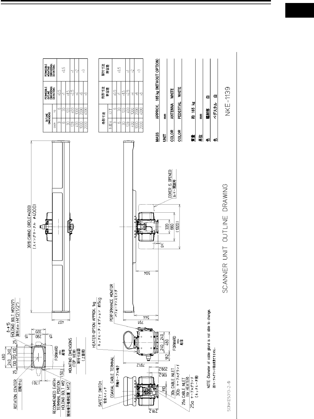
1-13 Section 1 Overview
1
2
3
4
5
6
7
8
9
10
11
12
13
14
15
16
17
18
19
20
21
22
23
24
25
26
27
付録
1.4 Structure
The dimensional outline drawing of this equipment is shown below.
Outline Drawing of Radar Antenna (NKE-1139)
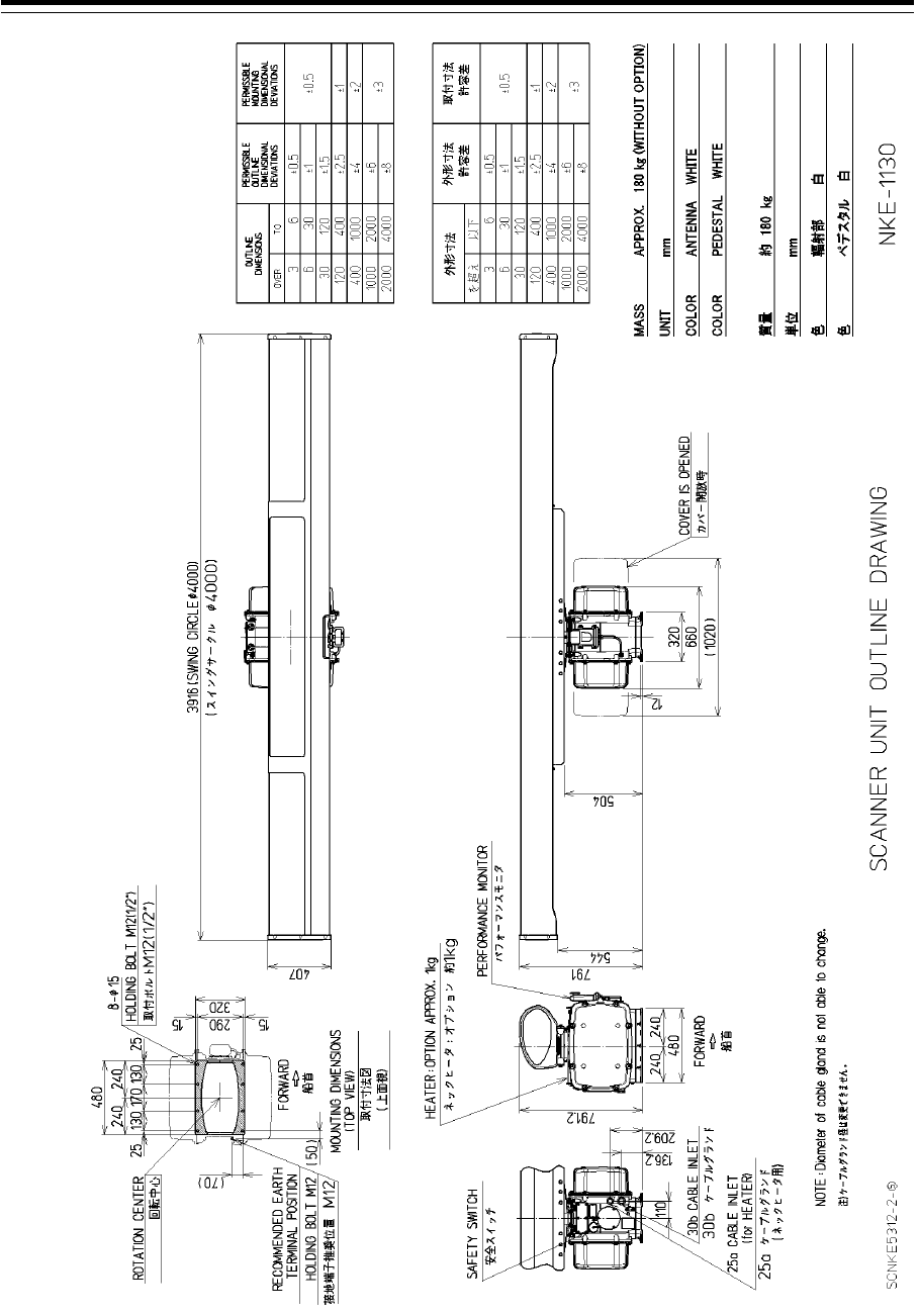
Section 1 Overview 1-14
Outline Drawing of Radar Antenna (NKE-1130)
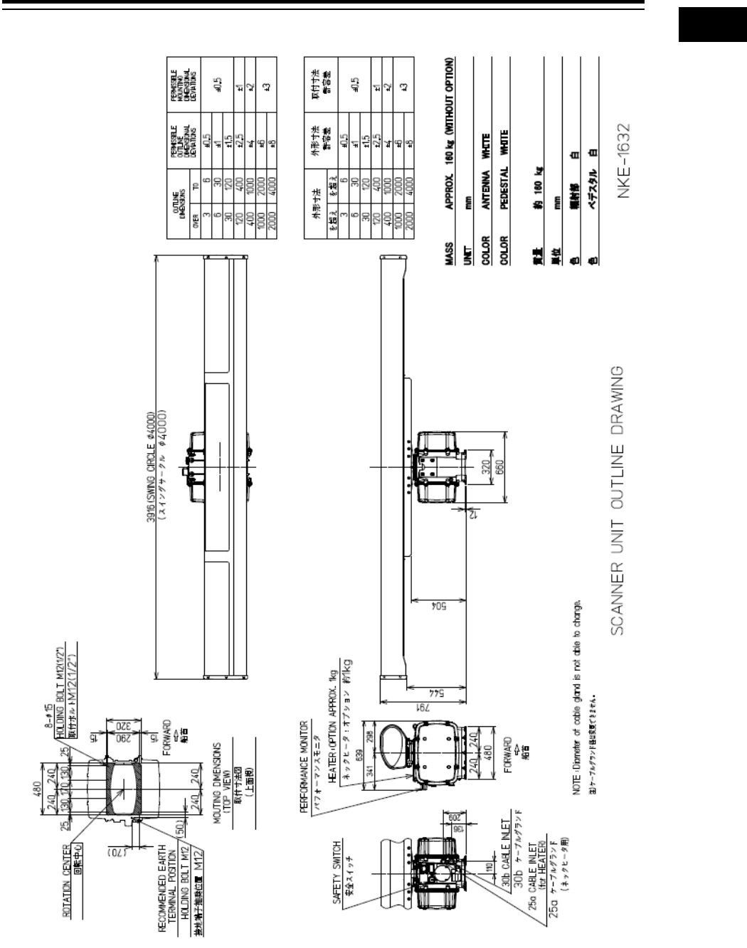
1-15 Section 1 Overview
1
2
3
4
5
6
7
8
9
10
11
12
13
14
15
16
17
18
19
20
21
22
23
24
25
26
27
付録
Outline Drawing of Radar Antenna (NKE-1632)
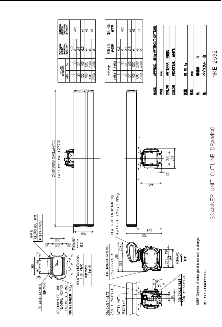
Section 1 Overview 1-16
Outline Drawing of Radar Antenna (NKE-2632)
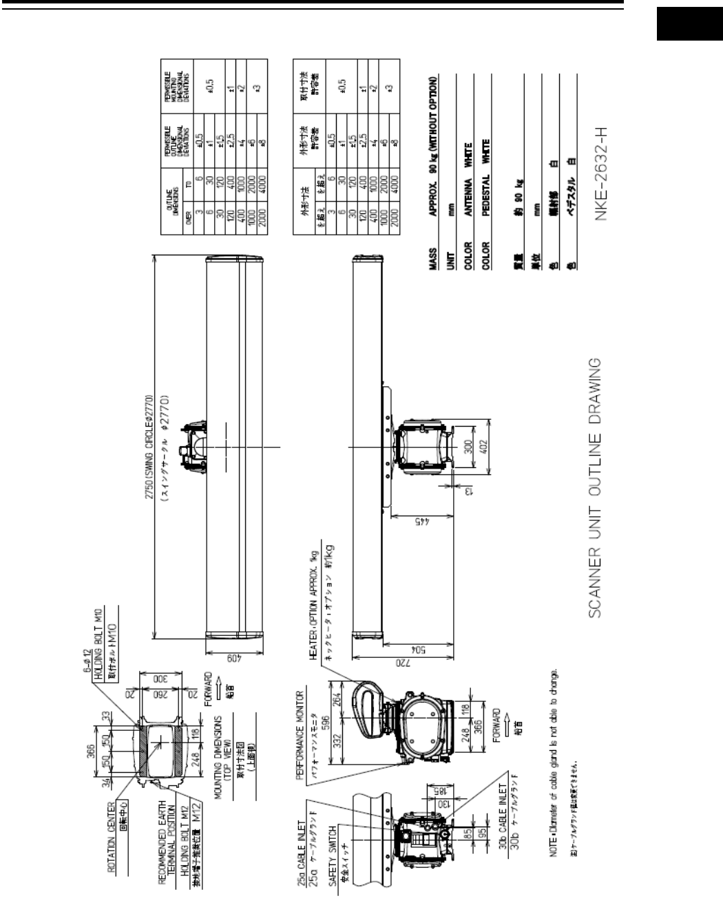
1-17 Section 1 Overview
1
2
3
4
5
6
7
8
9
10
11
12
13
14
15
16
17
18
19
20
21
22
23
24
25
26
27
付録
Outline Drawing of Radar Antenna (NKE-2632-H)
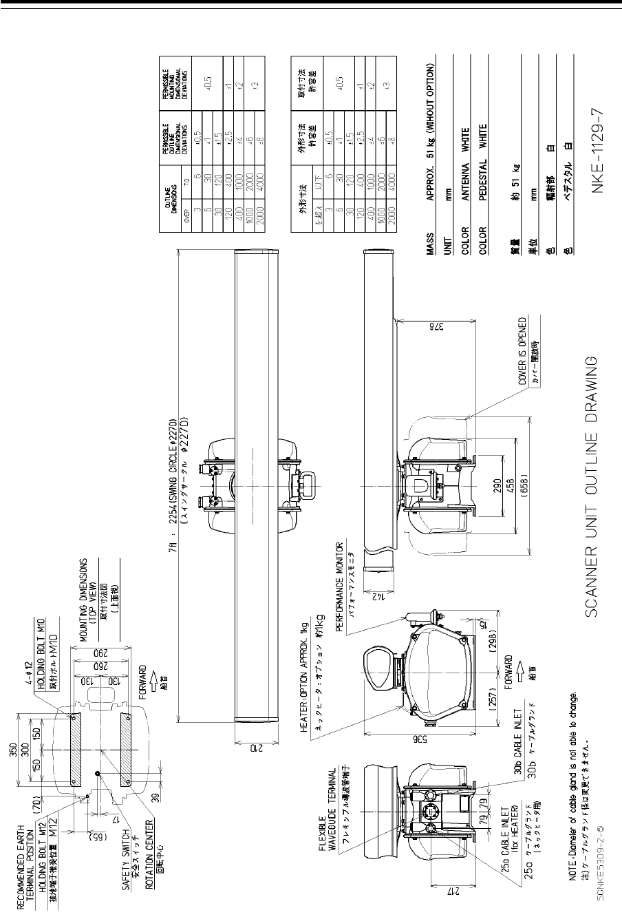
Section 1 Overview 1-18
Outline Drawing of Radar Antenna (NKE-1129-7)
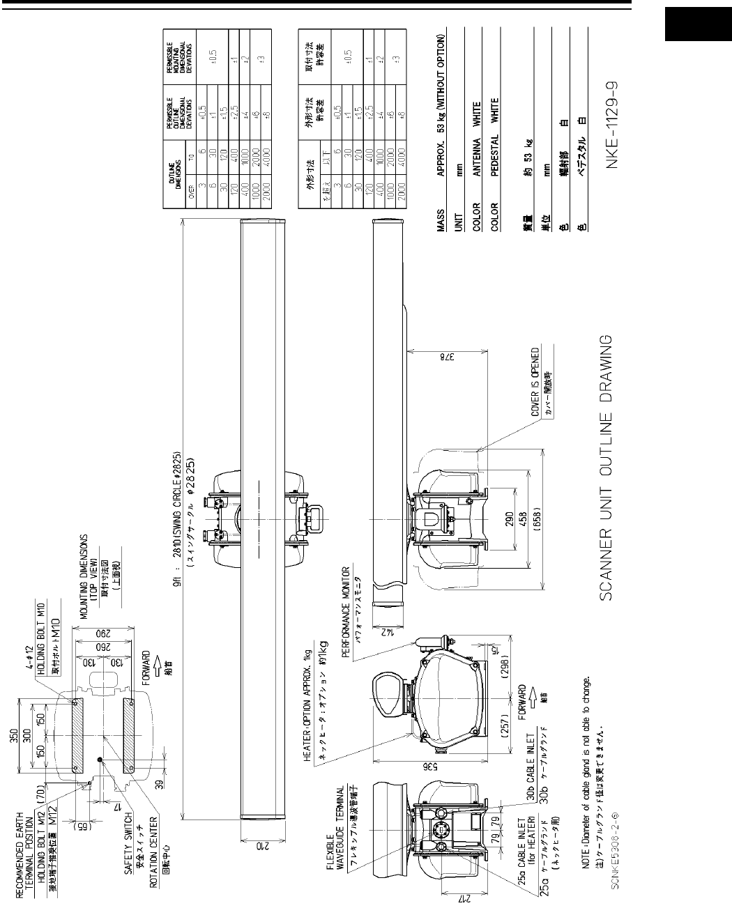
1-19 Section 1 Overview
1
2
3
4
5
6
7
8
9
10
11
12
13
14
15
16
17
18
19
20
21
22
23
24
25
26
27
付録
Outline Drawing of Radar Antenna (NKE-1129-9)
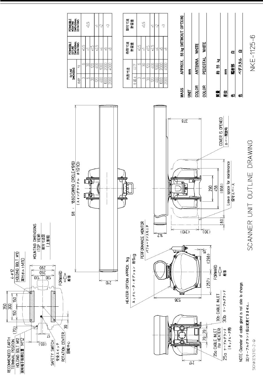
Section 1 Overview 1-20
Outline Drawing of Radar Antenna (NKE-1125-6)
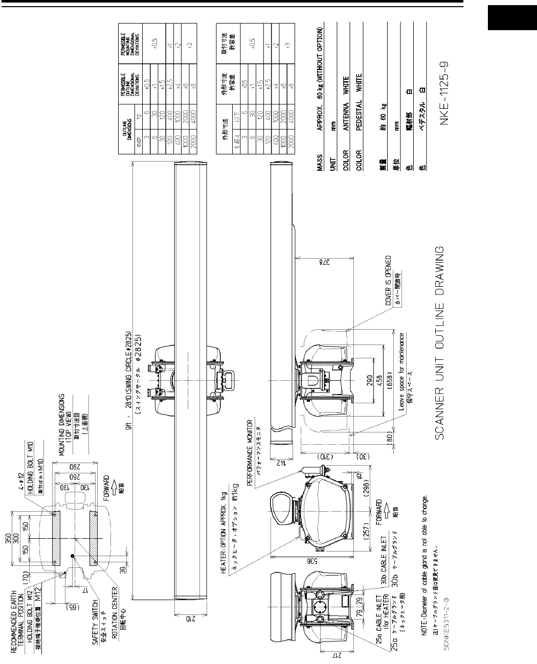
1-21 Section 1 Overview
1
2
3
4
5
6
7
8
9
10
11
12
13
14
15
16
17
18
19
20
21
22
23
24
25
26
27
付録
Outline Drawing of Radar Antenna (NKE-1125-9)
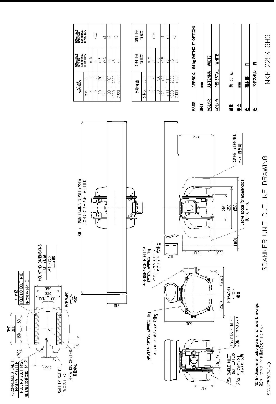
Section 1 Overview 1-22
Outline Drawing of Radar Antenna (NKE-2254-6HS)
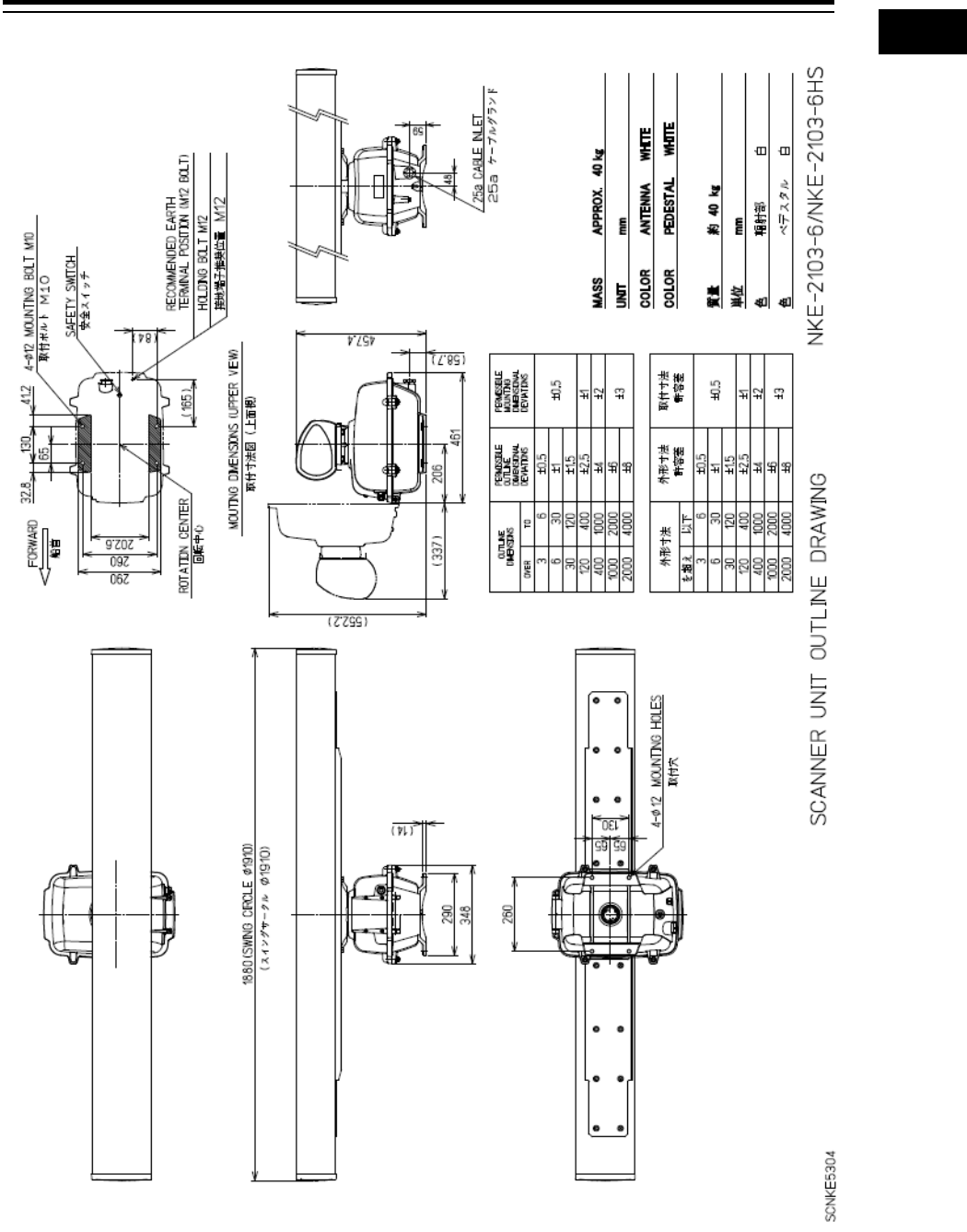
1-23 Section 1 Overview
1
2
3
4
5
6
7
8
9
10
11
12
13
14
15
16
17
18
19
20
21
22
23
24
25
26
27
付録
Outline Drawing of Radar Antenna (NKE-2103-6/6HS)
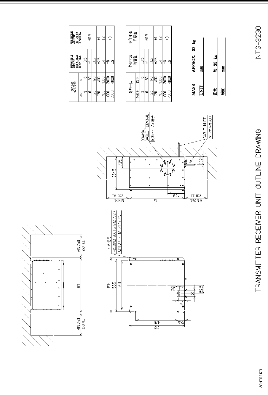
Section 1 Overview 1-24
Outline Drawing of Transmitter-Receiver Unit (NTG-3230)
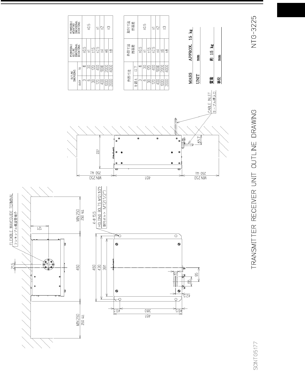
1-25 Section 1 Overview
1
2
3
4
5
6
7
8
9
10
11
12
13
14
15
16
17
18
19
20
21
22
23
24
25
26
27
付録
Outline Drawing of Transmitter-Receiver Unit (NTG-3225)
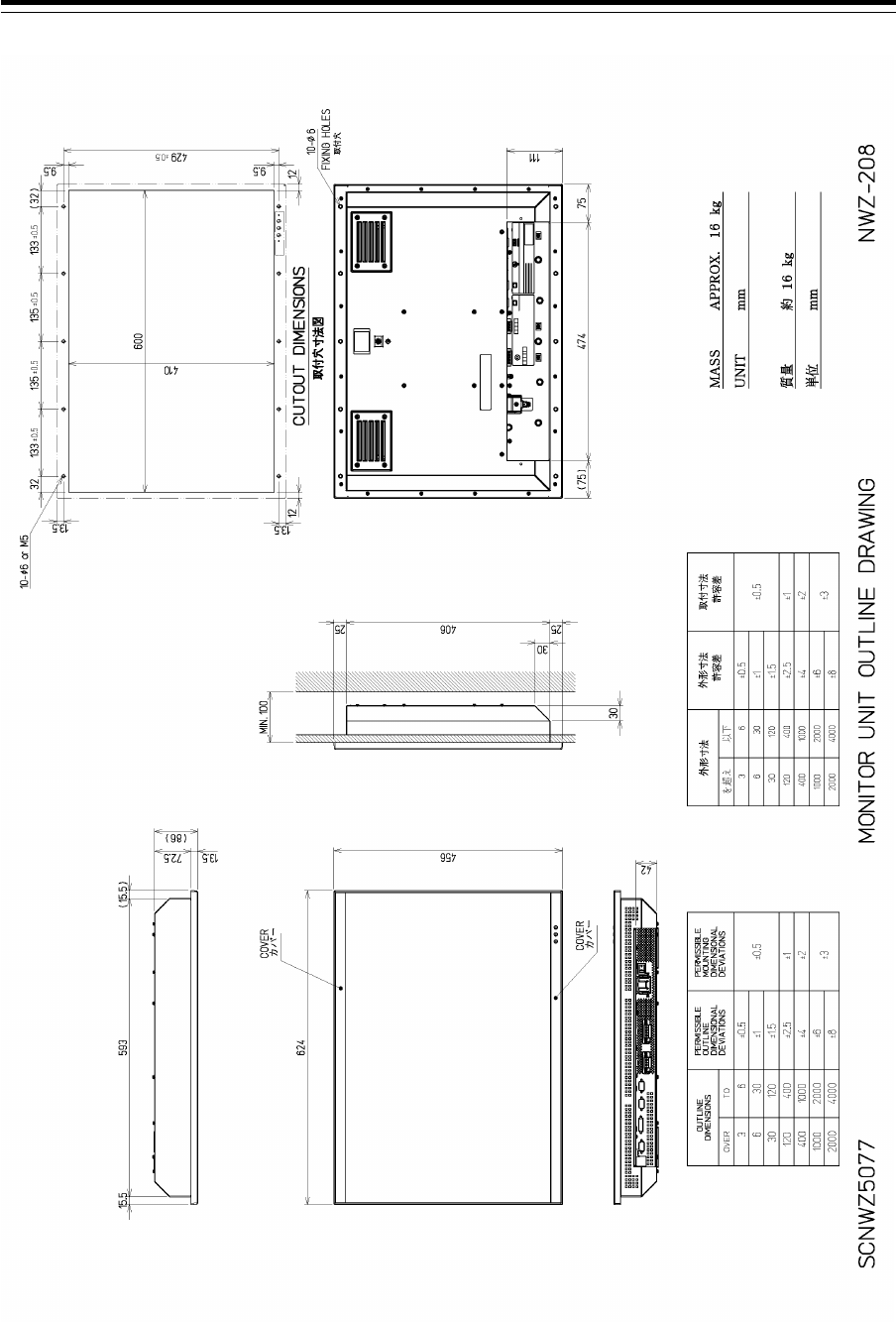
Section 1 Overview 1-26
Outline drawing of 26inch Display (NWZ-208)
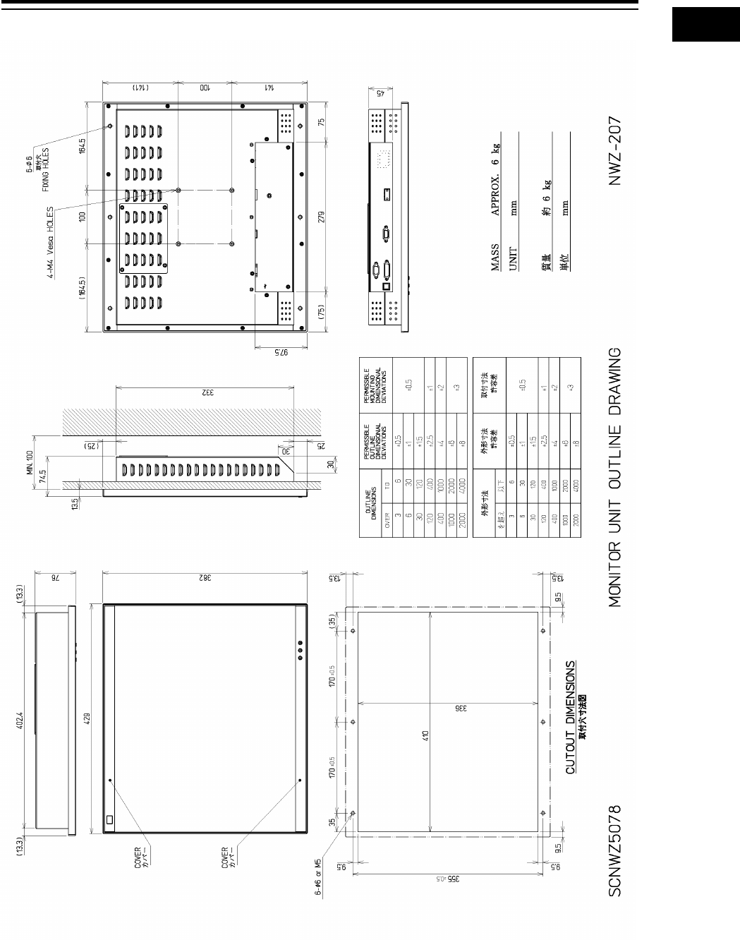
1-27 Section 1 Overview
1
2
3
4
5
6
7
8
9
10
11
12
13
14
15
16
17
18
19
20
21
22
23
24
25
26
27
付録
Outline drawing of 19inch Display (NWZ-207)
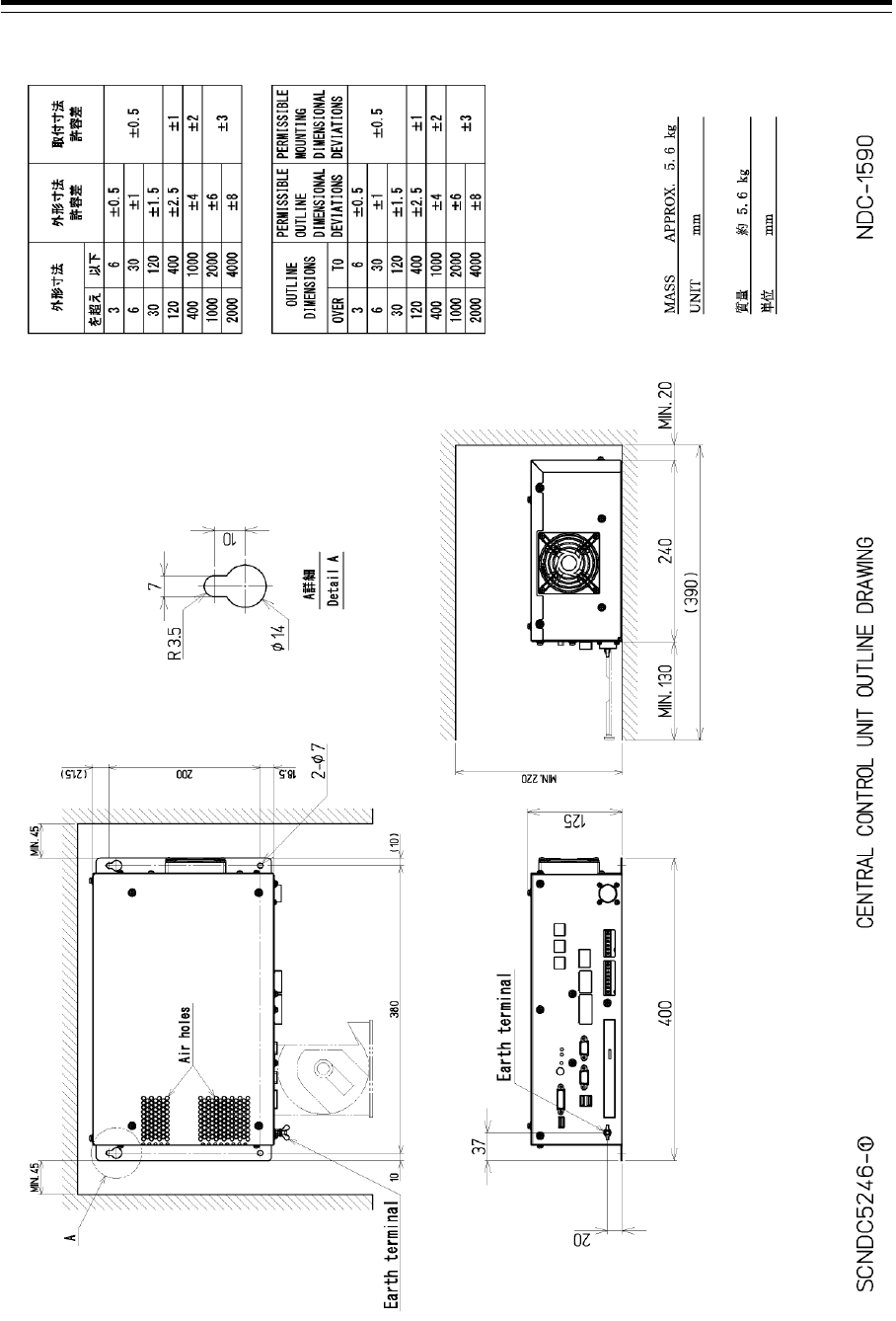
Section 1 Overview 1-28
Outline Drawing of Central Processing Unit (NDC-1590)
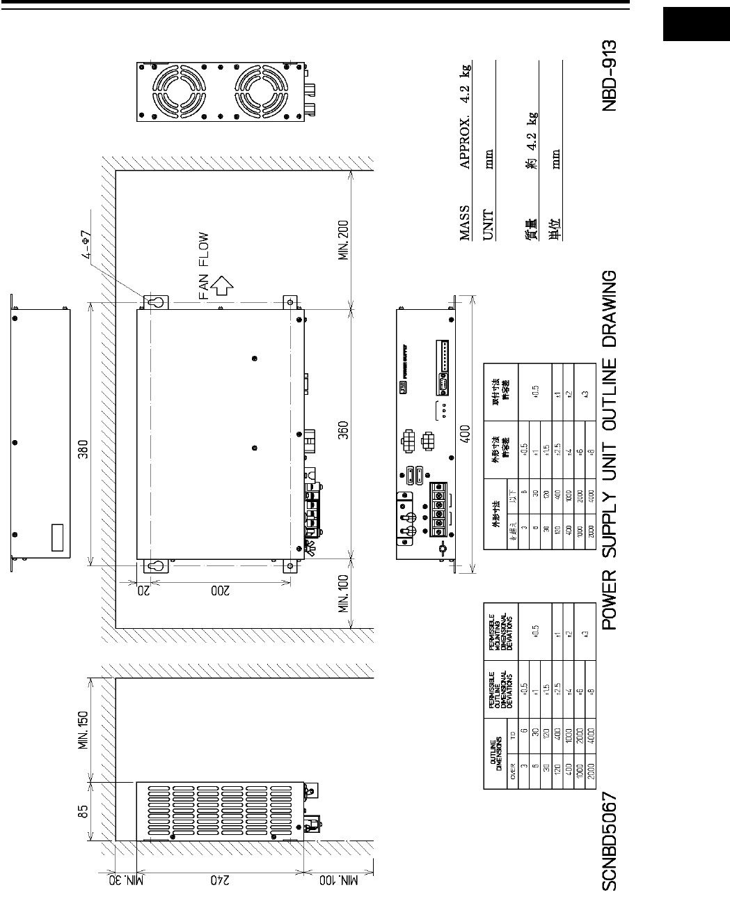
1-29 Section 1 Overview
1
2
3
4
5
6
7
8
9
10
11
12
13
14
15
16
17
18
19
20
21
22
23
24
25
26
27
付録
Outline Drawing of Power Supply Unit (NBD-913)
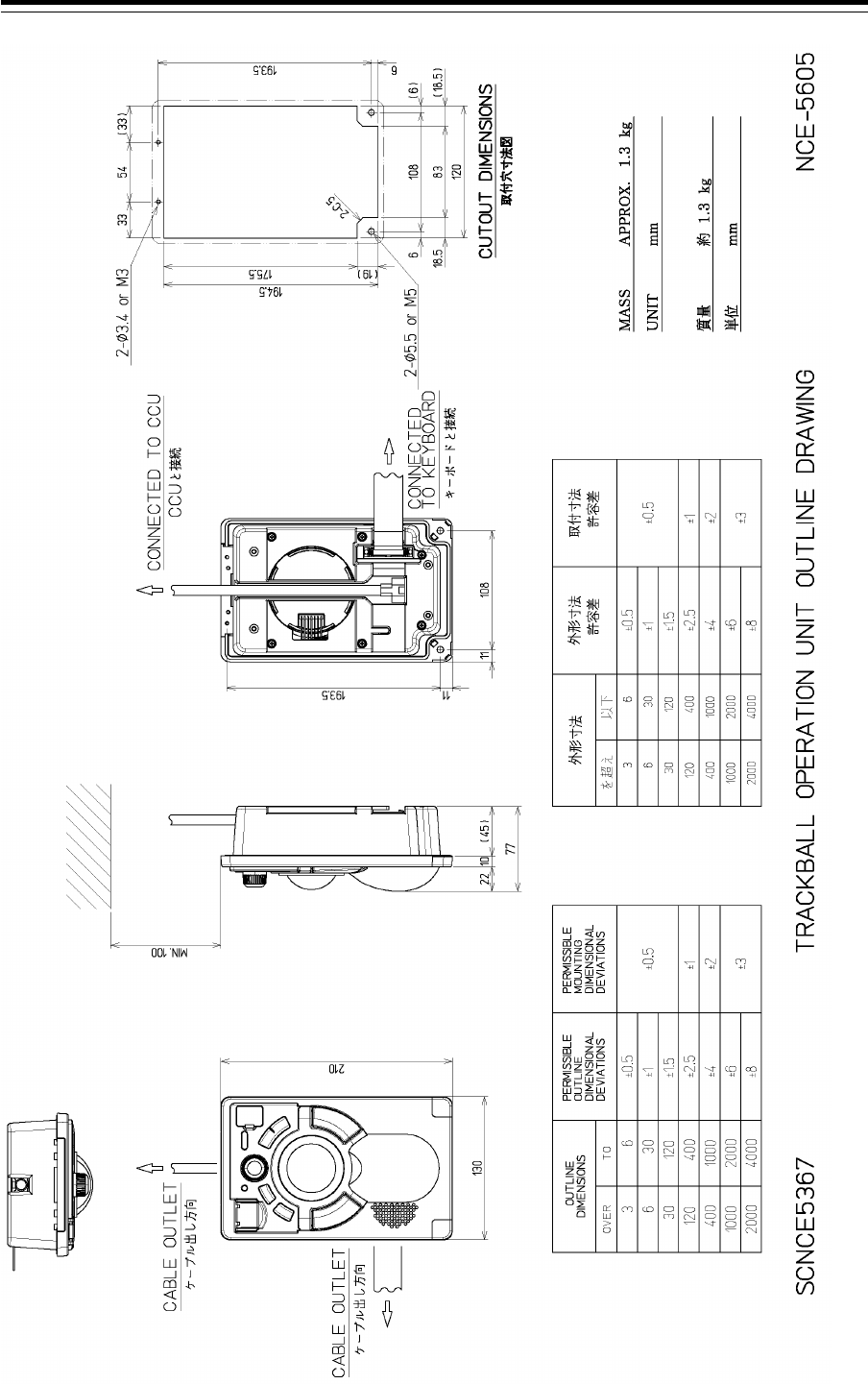
Section 1 Overview 1-30
Outline Drawing of Trackball Operation Unit (NCE-5605)
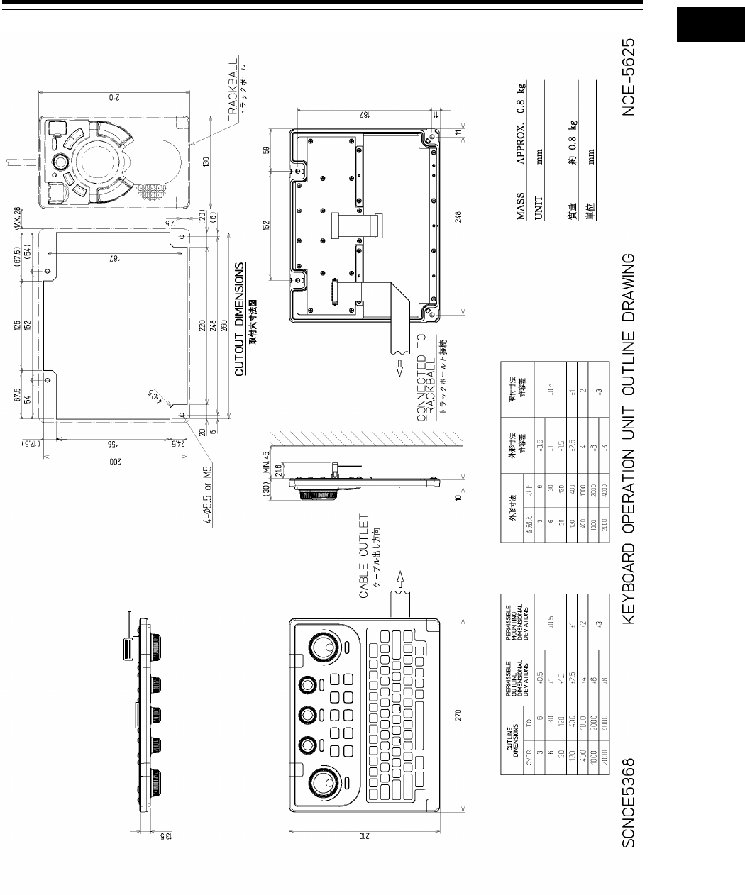
1-31 Section 1 Overview
1
2
3
4
5
6
7
8
9
10
11
12
13
14
15
16
17
18
19
20
21
22
23
24
25
26
27
付録
Outline Drawing of Keyboard Operation Unit (NCE-5625)
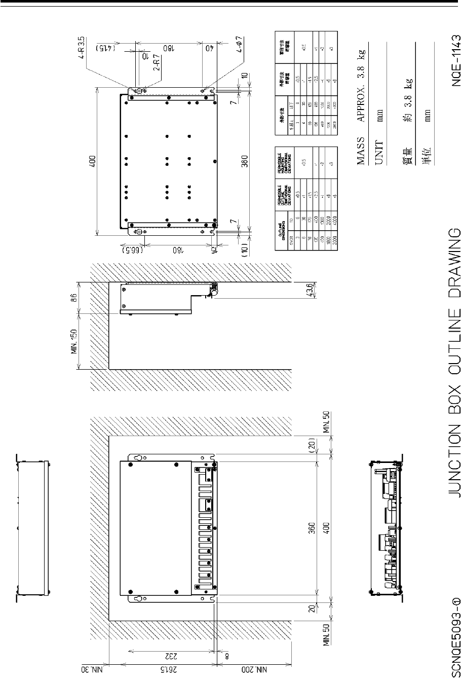
Section 1 Overview 1-32
Outline Drawing of Junction Box (NQE-1143)
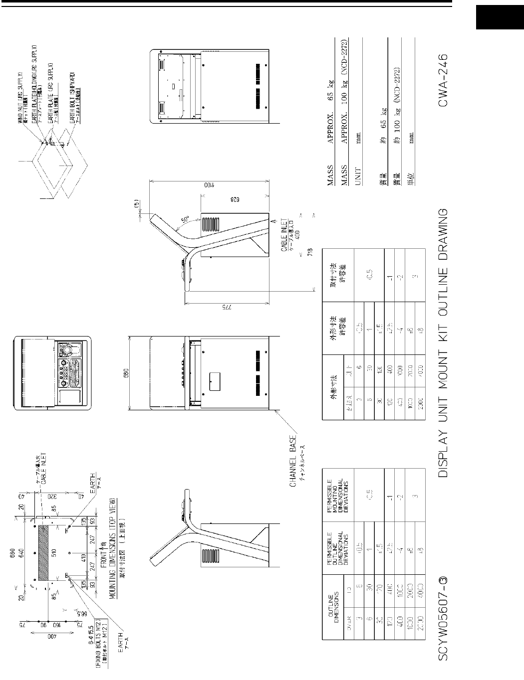
1-33 Section 1 Overview
1
2
3
4
5
6
7
8
9
10
11
12
13
14
15
16
17
18
19
20
21
22
23
24
25
26
27
付録
Outline Drawing of 26inch Cradle Frame (CWA-246)
(with display, trackball operation unit and keyboard operation unit installed)
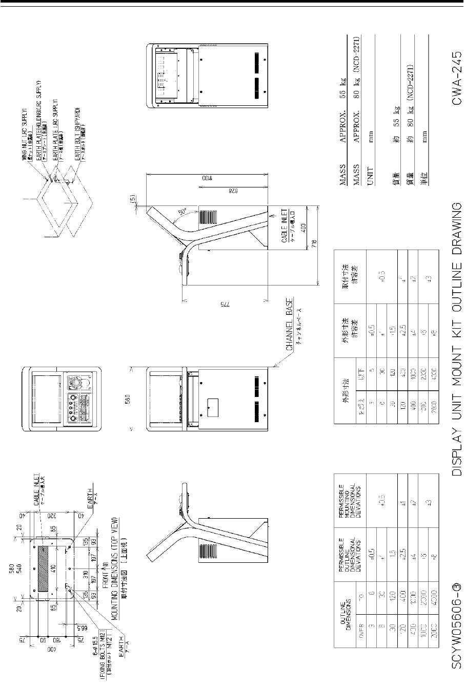
Section 1 Overview 1-34
Outline Drawing of 19inch Cradle Frame (CWA-245)
(with display, trackball operation unit and keyboard operation unit installed)
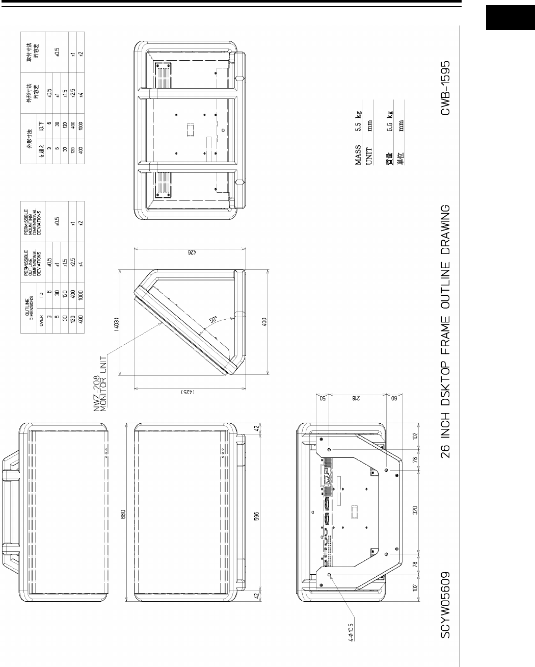
1-35 Section 1 Overview
1
2
3
4
5
6
7
8
9
10
11
12
13
14
15
16
17
18
19
20
21
22
23
24
25
26
27
付録
Outline Drawing of 26inch Desktop Frame (CWB-1595)
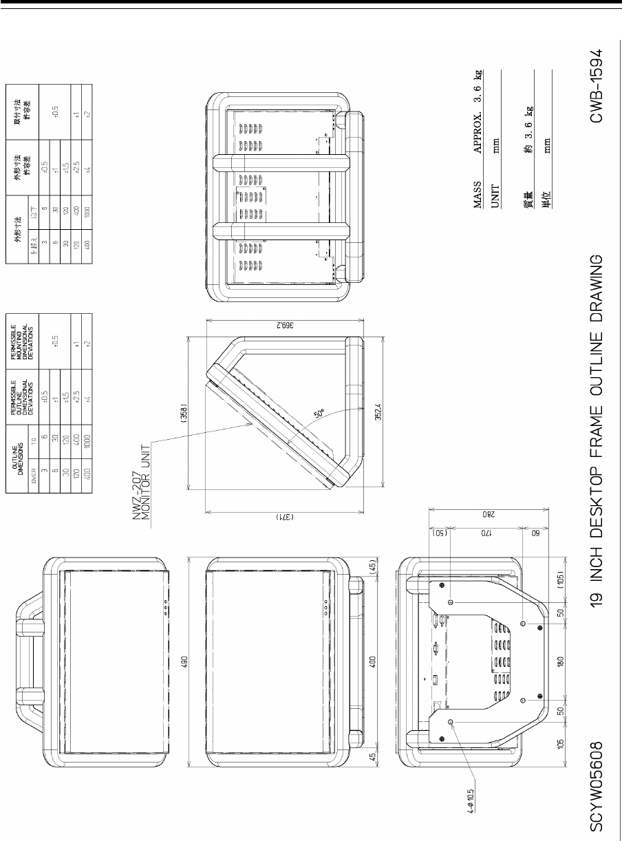
Section 1 Overview 1-36
Outline Drawing of 19inch Desktop Frame (CWB-1594)
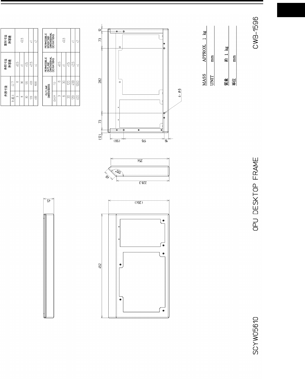
1-37 Section 1 Overview
1
2
3
4
5
6
7
8
9
10
11
12
13
14
15
16
17
18
19
20
21
22
23
24
25
26
27
付録
Outline Drawing of Operation Unit Desktop Frame (CWB-1596)
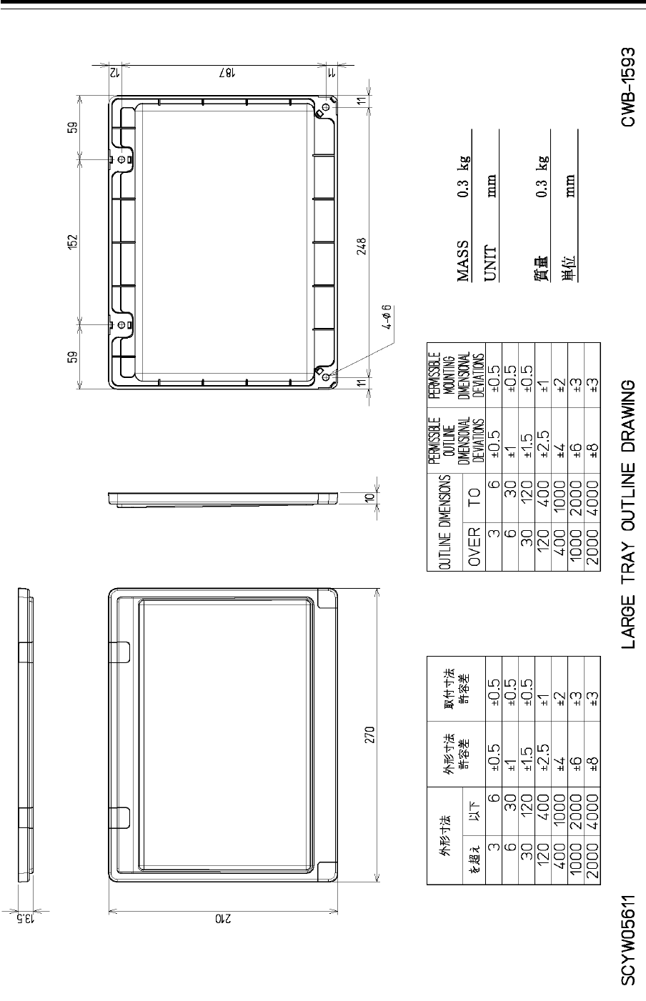
Section 1 Overview 1-38
Outline Drawing of Large Tray (CWB-1593)
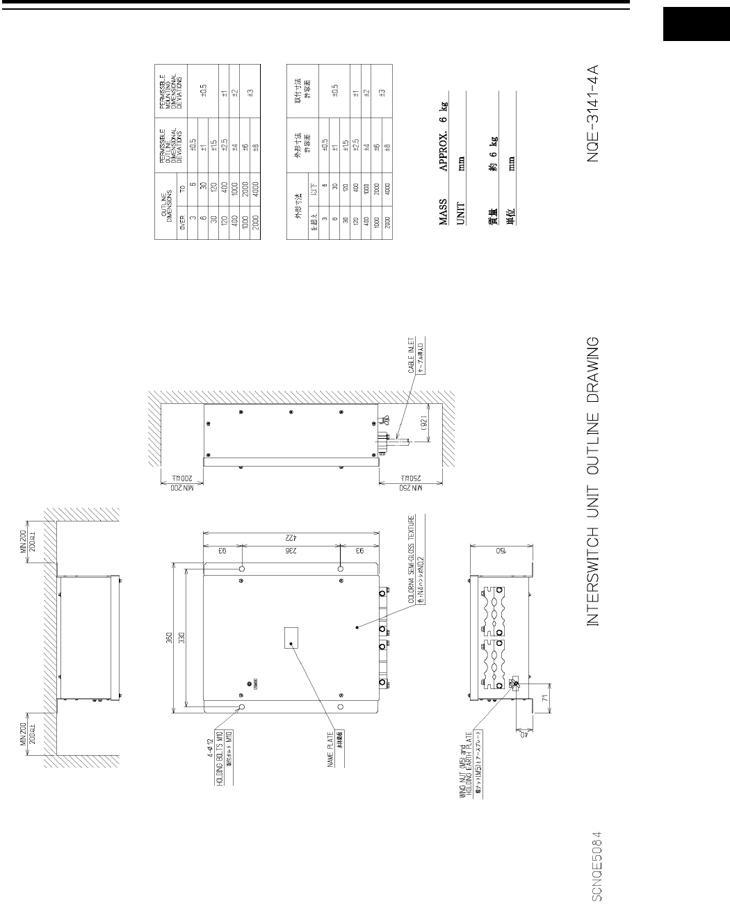
1-39 Section 1 Overview
1
2
3
4
5
6
7
8
9
10
11
12
13
14
15
16
17
18
19
20
21
22
23
24
25
26
27
付録
Outline Drawing of Interswitch Unit (NQE-3141-4A) (Option)
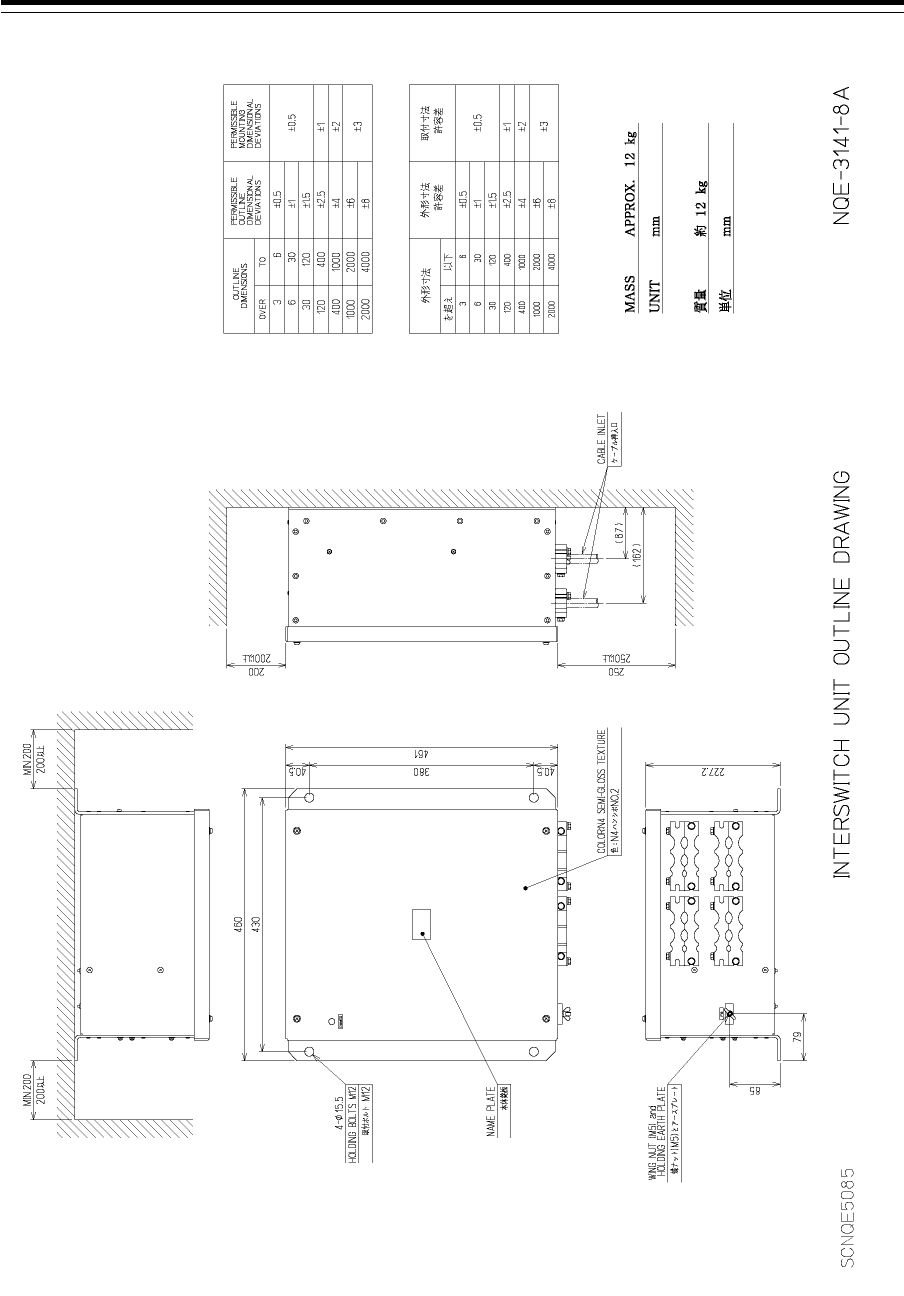
Section 1 Overview 1-40
Outline Drawing of Interswitch Unit (NQE-3141-8A) (Option)
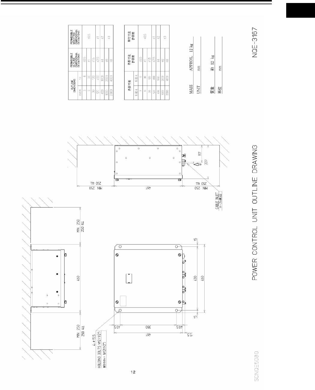
1-41 Section 1 Overview
1
2
3
4
5
6
7
8
9
10
11
12
13
14
15
16
17
18
19
20
21
22
23
24
25
26
27
付録
Outline Drawing of Power Control Unit (NQE-3167) (Option)
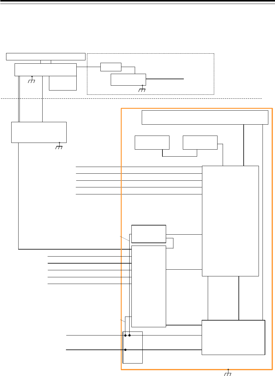
Section 1 Overview 1-42
1.5 General System Diagrams
Connection examples of this equipment are shown below.
150/250V TTYCSLA-4
AIS
(IEC61162-2)
GYRO COMPASS
(IEC61162-2)
No.1 DGPS
(IEC61162-1)
SDME
(IEC61162-1)
BNWAS
(Dry Contact)
CML-836AC
W851:7ZCNA4158(0.85m)
CML-836AC
W841:7ZCNA4164(1m)
CAT-5 LAN Cable
NQE-1143
Junction Box
(Option)
Upper Deck
Lower Deck
NKE-1139
Scanner Unit
NCE-5605
Trackball Operation Unit
NBD-913
Power Supply Unit
NJU-84
Performance
Monitor
2695110056 14 Cores Composite Cable
NOTE: ELIMINATING THE INTERFERENCE ON FREQUENCIES USED FOR MARINE COMMUNICATIONS AND
NAVIGATION DUE TO OPERATION OF THE RADAR,
ALL CABLES OF THE RADAR ARE TO BE RUN AWAY FROM THE CABLES OF RADIO EQUIPMENT.
(ex. RADIOTELEPHONE, COMMUNICATIONS RECEIVER and DIRECTION FINDER. etc..)
ESPECIALLY INTER-WIRING CABLES BETWEEN SCANNER UNIT AND DISPLAY UNIT OF THE RADAR
SHOULD NOT BE RUN PARALLEL WITH THE CABLES OF RADIO EQUIPMENT.
150/250V TTYCSLA-1
150/250V TTYCSLA-1
150/250V TTYCSLA-1
150/250V TTYCSLA-1
NWZ-208
26inch Monitor Unit
CML-901
W71:7ZCNA4147(0.65m)
CML-901
W61:7ZCNA4151(0.75m)
CML-901
W73:7ZCNA4149(1.05m)
(5A)
NBL-175
Step down Transformer
1600VA
0.6/1kV DPYCYS-1.5
Ship’s Main AC 220V
For Heater
Circuit Breaker
(Dock Supply)
Option
NTG-3230
Transmitter Receiver Unit
NCE-5625
Keyboard Operation Unit
(Option)
W64:7ZCNA4187(0.40m)
CWA-246 26inch Display Unit Mount Kit
Coaxial Cable
HF-20D
150/250V TTYCSLA-4
AIS
(IEC61162-2)
GYRO COMPASS
(IEC61162-2)
No.1 DGPS
(IEC61162-1)
SDME
(IEC61162-1)
BNWAS
(Dry Contact)
150/250V TTYCSLA-1
150/250V TTYCSLA-1
150/250V TTYCSLA-1
150/250V TTYCSLA-1
2695110056
14 Cores Composite Cable
CAT-5 LAN Cable
NDC-1590
Central Control Unit
CML-901
W53:7ZCNA4156A(0.55m)
CML-901
W51:7ZCNA4154(0.8m)
NQA-2443
Sensor LAN
Switch Unit
(Option)
Inner wiring
24VDC/Max2A
(For Junction Box:SLC)
Inner wiring
24VDC/Max0.4A
(For LAN Unit)
CQD-2312
Relay
Terminal
Transitional Source of
Emergency Electric Power
24VDC/Max300W
0.6/1kV DPYCYS-16
0.6/1kV DPYCY-6
Ship's Main
AC220V 1PH/Max1900VA
Inner wiring
24VDC
Inner wiring
AC220V 1PH
General System Diagram of JMR-9230-S3
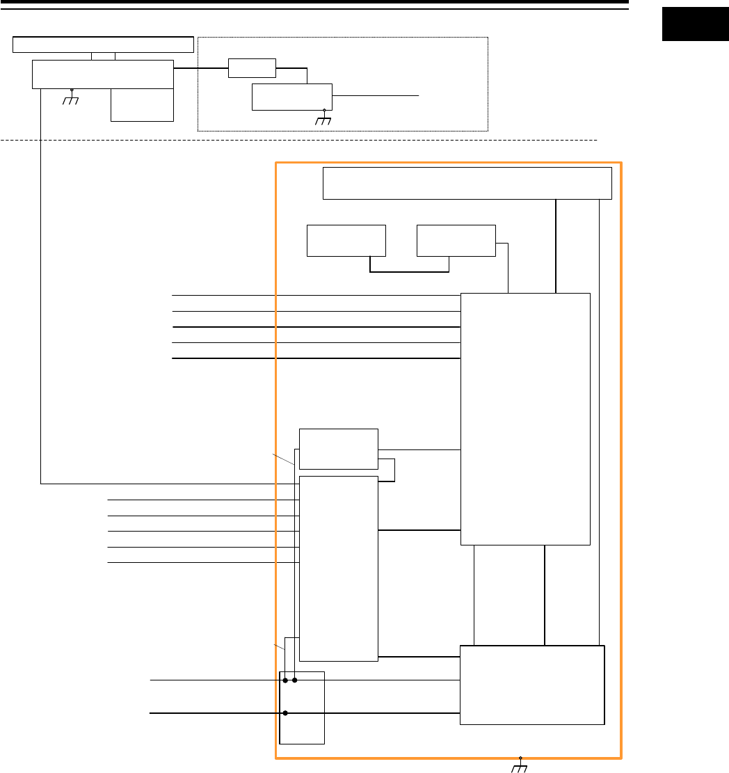
1-43 Section 1 Overview
1
2
3
4
5
6
7
8
9
10
11
12
13
14
15
16
17
18
19
20
21
22
23
24
25
26
27
付録
150/250V TTYCSLA-4
AIS
(IEC61162-2)
GYRO COMPASS
(IEC61162-2)
No.1 DGPS
(IEC61162-1)
SDME
(IEC61162-1)
BNWAS
(Dry Contact)
Upper Deck
Lower Deck
NKE-1130
Scanner Unit
NJU-84
Performance
Monitor
2695110056 14 Cores Composite Cable
150/250V TTYCSLA-1
150/250V TTYCSLA-1
150/250V TTYCSLA-1
150/250V TTYCSLA-1
(5A)
NBL-175
Step down Transformer
1600VA
0.6/1kV DPYCYS-1.5
Ship’s Main AC 220V
For Heater
Circuit Breaker
(Dock Supply)
Option
150/250V TTYCSLA-4
AIS
(IEC61162-2)
GYRO COMPASS
(IEC61162-2)
No.1 DGPS
(IEC61162-1)
SDME
(IEC61162-1)
BNWAS
(Dry Contact)
150/250V TTYCSLA-1
150/250V TTYCSLA-1
150/250V TTYCSLA-1
150/250V TTYCSLA-1
NOTE: ELIMINATING THE INTERFERENCE ON FREQUENCIES USED FOR MARINE COMMUNICATIONS AND
NAVIGATION DUE TO OPERATION OF THE RADAR,
ALL CABLES OF THE RADAR ARE TO BE RUN AWAY FROM THE CABLES OF RADIO EQUIPMENT.
(ex. RADIOTELEPHONE, COMMUNICATIONS RECEIVER and DIRECTION FINDER. etc..)
ESPECIALLY INTER-WIRING CABLES BETWEEN SCANNER UNIT AND DISPLAY UNIT OF THE RADAR
SHOULD NOT BE RUN PARALLEL WITH THE CABLES OF RADIO EQUIPMENT.
CML-836AC
W851:7ZCNA4158(0.85m)
CML-836AC
W841:7ZCNA4164(1m)
CAT-5 LAN Cable
NQE-1143
Junction Box
(Option)
NCE-5605
Trackball Operation Unit
NBD-913
Power Supply Unit
NWZ-208
26inch Monitor Unit
CML-901
W71:7ZCNA4147(0.65m)
CML-901
W61:7ZCNA4151(0.75m)
CML-901
W73:7ZCNA4149(1.05m)
NCE-5625
Keyboard Operation Unit
(Option)
W64:7ZCNA4187(0.40m)
CWA-246 26inch Display Unit Mount Kit
CAT-5 LAN Cable
NDC-1590
Central Control Unit
CML-901
W53:7ZCNA4156A(0.55m)
CML-901
W51:7ZCNA4154(0.8m)
NQA-2443
Sensor LAN
Switch Unit
(Option)
Inner wiring
24VDC/Max2A
(For Junction Box:SLC)
Inner wiring
24VDC/Max0.4A
(For LAN Unit)
CQD-2312
Relay
Terminal
Transitional Source of
Emergency Electric Power
24VDC/Max300W
0.6/1kV DPYCYS-16
0.6/1kV DPYCY-6
Ship's Main
AC220V 1PH/MAX1900VA
Inner wiring
24VDC
Inner wiring
AC220V 1PH
General System Diagram of JMR-9230-S
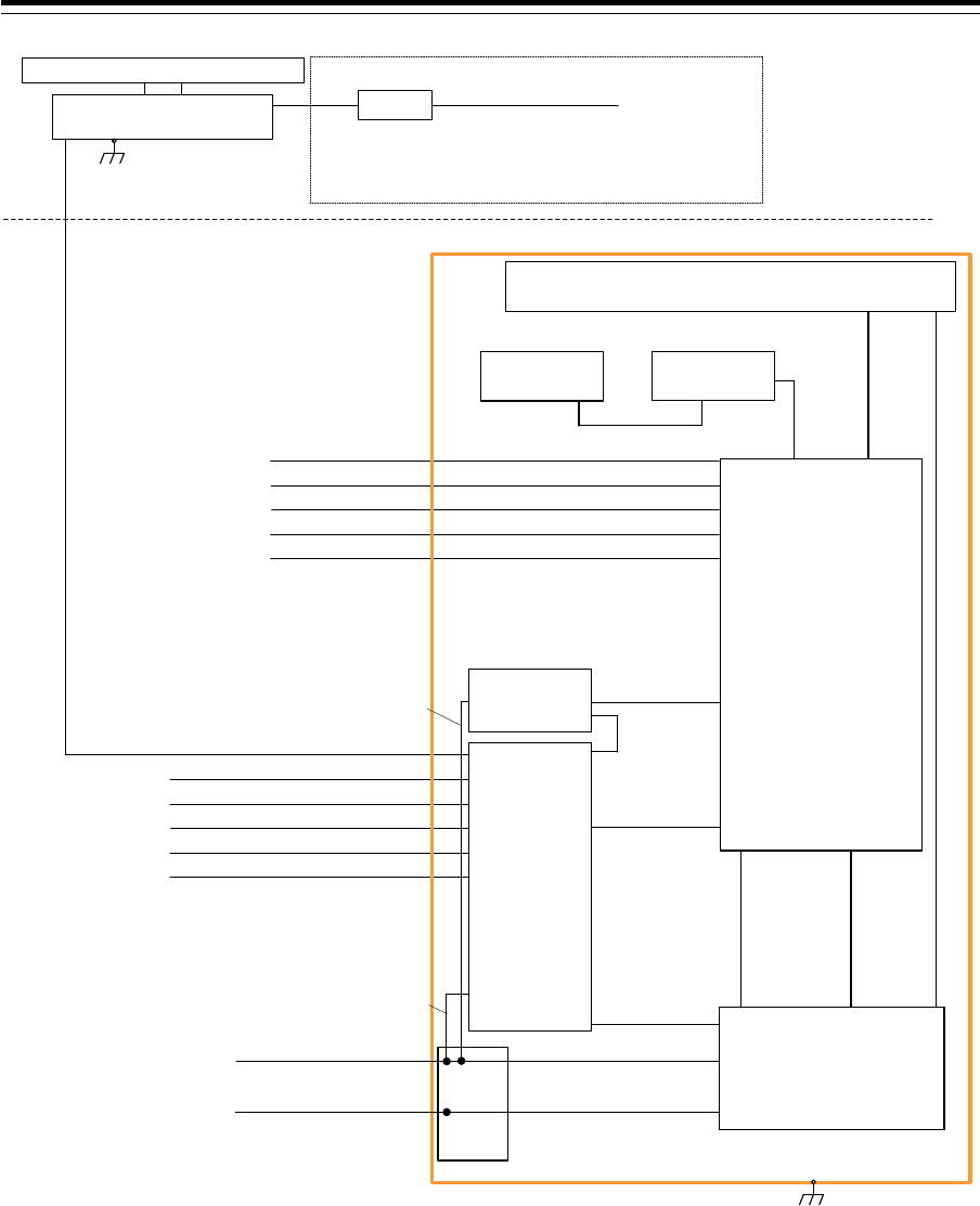
Section 1 Overview 1-44
150/250V TTYCSLA-4
AIS
(IEC61162-2)
GYRO COMPASS
(IEC61162-2)
No.1 DGPS
(IEC61162-1)
SDME
(IEC61162-1)
BNWAS
(Dry Contact)
Upper Deck
Lower Deck
NKE-1632
Scanner Unit
2695110056 14 Cores Composite Cable
150/250V TTYCSLA-1
150/250V TTYCSLA-1
150/250V TTYCSLA-1
150/250V TTYCSLA-1
150/250V TTYCSLA-4
AIS
(IEC61162-2)
GYRO COMPASS
(IEC61162-2)
No.1 DGPS
(IEC61162-1)
SDME
(IEC61162-1)
BNWAS
(Dry Contact)
150/250V TTYCSLA-1
150/250V TTYCSLA-1
150/250V TTYCSLA-1
150/250V TTYCSLA-1
(5A)
Circuit Breaker
(Dock Supply)
Option
0.6/1kV DPYCYS-1.5 Ship’s Main AC100V / 220V
For Heater
NOTE: ELIMINATING THE INTERFERENCE ON FREQUENCIES USED FOR MARINE COMMUNICATIONS AND
NAVIGATION DUE TO OPERATION OF THE RADAR,
ALL CABLES OF THE RADAR ARE TO BE RUN AWAY FROM THE CABLES OF RADIO EQUIPMENT.
(ex. RADIOTELEPHONE, COMMUNICATIONS RECEIVER and DIRECTION FINDER. etc..)
ESPECIALLY INTER-WIRING CABLES BETWEEN SCANNER UNIT AND DISPLAY UNIT OF THE RADAR
SHOULD NOT BE RUN PARALLEL WITH THE CABLES OF RADIO EQUIPMENT.
CML-836AC
W851:7ZCNA4158(0.85m)
CML-836AC
W841:7ZCNA4164(1m)
CAT-5 LAN Cable
NQE-1143
Junction Box
(Option)
NCE-5605
Trackball Operation Unit
NBD-913
Power Supply Unit
NWZ-208
26inch Monitor Unit
CML-901
W71:7ZCNA4147(0.65m)
CML-901
W61:7ZCNA4151(0.75m)
CML-901
W73:7ZCNA4149(1.05m)
NCE-5625
Keyboard Operation Unit
(Option)
W64:7ZCNA4187(0.40m)
CWA-246 26inch Display Unit Mount Kit
CAT-5 LAN Cable
NDC-1590
Central Control Unit
CML-901
W53:7ZCNA4156A(0.55m)
CML-901
W51:7ZCNA4154(0.8m)
NQA-2443
Sensor LAN
Switch Unit
(Option)
Inner wiring
24VDC/Max2A
(For Junction Box:SLC)
Inner wiring
24VDC/Max0.4A
(For LAN Unit)
CQD-2312
Relay
Terminal
Transitional Source of
Emergency Electric Power
24VDC/Max300W
0.6/1kV DPYCYS-16
0.6/1kV DPYCY-6
Ship's Main
AC220V 1PH/Max1900VA
Inner wiring
24VDC
Inner wiring
AC220V 1PH
General System Diagram of JMR-9272-S

1-45 Section 1 Overview
1
2
3
4
5
6
7
8
9
10
11
12
13
14
15
16
17
18
19
20
21
22
23
24
25
26
27
付録
150
/250V TTYCSLA-4
AIS
(IEC61162-2)
GYRO COMPASS
(IEC61162-2)
No.1 DGPS
(IEC61162-1)
SDME
(IEC61162-1)
BNWAS
(Dry Contact)
Upper Deck
Lower Deck
NKE-2632
Scanner Unit
2695110056 14 Cores Composite Cable
150/250V TTYCSLA-1
150/250V TTYCSLA-1
150/250V TTYCSLA-1
150/250V TTYCSLA-1
150/250V TTYCSLA-4
AIS
(IEC61162-2)
GYRO COMPASS
(IEC61162-2)
No.1 DGPS
(IEC61162-1)
SDME
(IEC61162-1)
BNWAS
(Dry Contact)
150/250V TTYCSLA-1
150/250V TTYCSLA-1
150/250V TTYCSLA-1
150/250V TTYCSLA-1
(5A)
Circuit Breaker
(Dock Supply)
Option
0.6/1kV DPYCYS-1.5 Ship’s Main AC100V / 220V
For Heater
NOTE: ELIMINATING THE INTERFERENCE ON FREQUENCIES USED FOR MARINE COMMUNICATIONS AND
NAVIGATION DUE TO OPERATION OF THE RADAR,
ALL CABLES OF THE RADAR ARE TO BE RUN AWAY FROM THE CABLES OF RADIO EQUIPMENT.
(ex. RADIOTELEPHONE, COMMUNICATIONS RECEIVER and DIRECTION FINDER. etc..)
ESPECIALLY INTER-WIRING CABLES BETWEEN SCANNER UNIT AND DISPLAY UNIT OF THE RADAR
SHOULD NOT BE RUN PARALLEL WITH THE CABLES OF RADIO EQUIPMENT.
CML-836AC
W851:7ZCNA4158(0.85m)
CML-836AC
W841:7ZCNA4164(1m)
CAT-5 LAN Cable
NQE-1143
Junction Box
(Option)
NCE-5605
Trackball Operation Unit
NBD-913
Power Supply Unit
NWZ-208
26inch Monitor Unit
CML-901
W71:7ZCNA4147(0.65m)
CML-901
W61:7ZCNA4151(0.75m)
CML-901
W73:7ZCNA4149(1.05m)
NCE-5625
Keyboard Operation Unit
(Option)
W64:7ZCNA4187(0.40m)
CWA-246 26inch Display Unit Mount Kit
CAT-5 LAN Cable
NDC-1590
Central Control Unit
CML-901
W53:7ZCNA4156A(0.55m)
CML-901
W51:7ZCNA4154(0.8m)
NQA-2443
Sensor LAN
Switch Unit
(Option)
Inner wiring
24VDC/Max2A
(For Junction Box:SLC)
Inner wiring
24VDC/Max0.4A
(For LAN Unit)
CQD-2312
Relay
Terminal
Transitional Source of
Emergency Electric Power
24VDC/Max300W
0.6/1kV DPYCYS-16
0.6/1kV DPYCY-6
Ship's Main
AC220V 1PH/Max1500VA
Inner wiring
24VDC
Inner wiring
AC220V 1PH
General System Diagram of JMR-9282-S
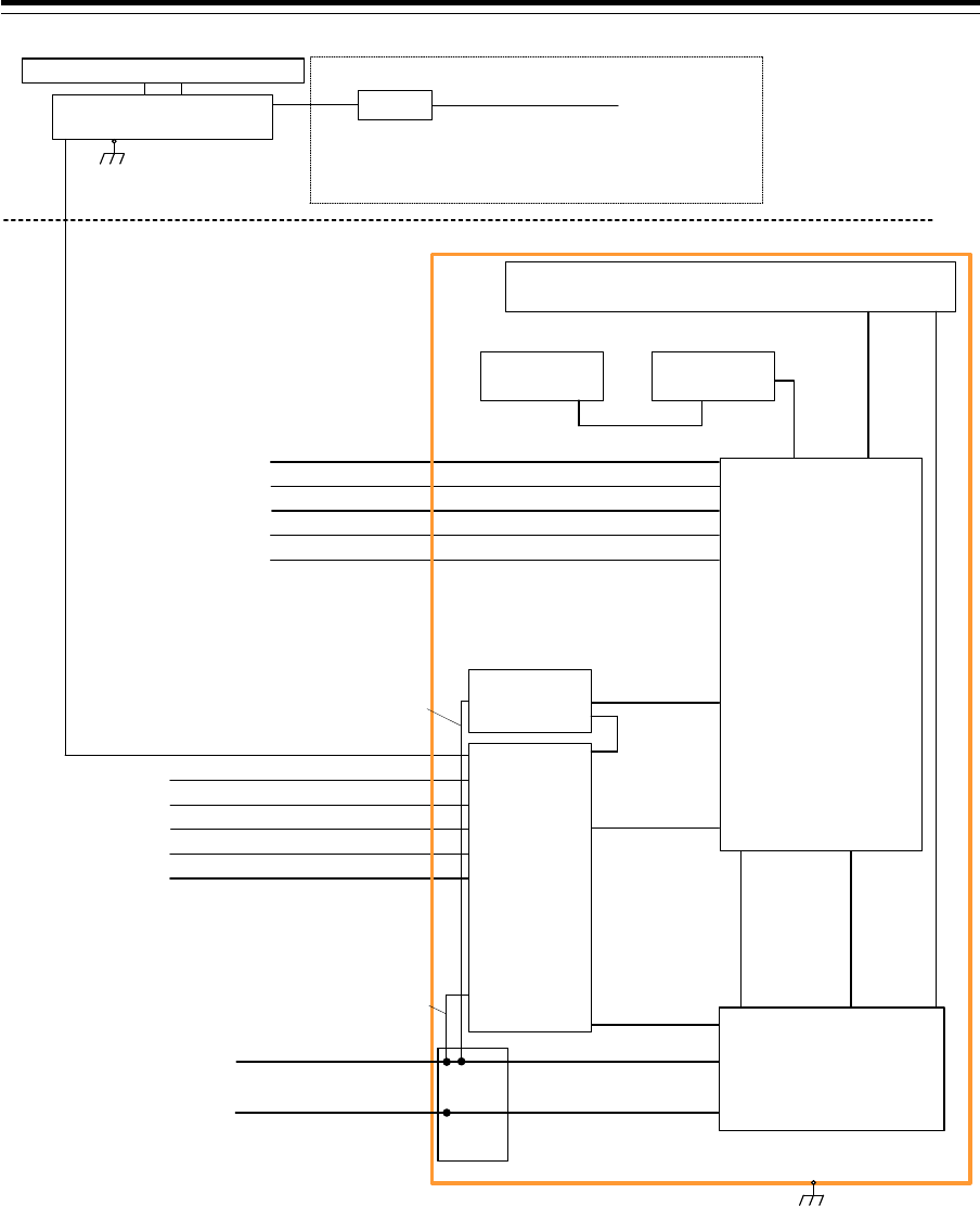
Section 1 Overview 1-46
150/250V TTYCSLA-4
AIS
(IEC61162-2)
GYRO COMPASS
(IEC61162-2)
No.1 DGPS
(IEC61162-1)
SDME
(IEC61162-1)
BNWAS
(Dry Contact)
Upper Deck
Lower Deck
NKE-2632-H
Scanner Unit
2695110056 14 Cores Composite Cable
150/250V TTYCSLA-1
150/250V TTYCSLA-1
150/250V TTYCSLA-1
150/250V TTYCSLA-1
150/250V TTYCSLA-4
AIS
(IEC61162-2)
GYRO COMPASS
(IEC61162-2)
No.1 DGPS
(IEC61162-1)
SDME
(IEC61162-1)
BNWAS
(Dry Contact)
150/250V TTYCSLA-1
150/250V TTYCSLA-1
150/250V TTYCSLA-1
150/250V TTYCSLA-1
(5A)
Circuit Breaker
(Dock Supply)
Option
0.6/1kV DPYCYS-1.5
Ship’s Main AC100V / 220V
For Heater
NOTE: ELIMINATING THE INTERFERENCE ON FREQUENCIES USED FOR MARINE COMMUNICATIONS AND
NAVIGATION DUE TO OPERATION OF THE RADAR,
ALL CABLES OF THE RADAR ARE TO BE RUN AWAY FROM THE CABLES OF RADIO EQUIPMENT.
(ex. RADIOTELEPHONE, COMMUNICATIONS RECEIVER and DIRECTION FINDER. etc..)
ESPECIALLY INTER-WIRING CABLES BETWEEN SCANNER UNIT AND DISPLAY UNIT OF THE RADAR
SHOULD NOT BE RUN PARALLEL WITH THE CABLES OF RADIO EQUIPMENT.
CML-836AC
W851:7ZCNA4158(0.85m)
CML-836AC
W841:7ZCNA4164(1m)
CAT-5 LAN Cable
NQE-1143
Junction Box
(Option)
NCE-5605
Trackball Operation Unit
NBD-913
Power Supply Unit
NWZ-208
26inch Monitor Unit
CML-901
W71:7ZCNA4147(0.65m)
CML-901
W61:7ZCNA4151(0.75m)
CML-901
W73:7ZCNA4149(1.05m)
NCE-5625
Keyboard Operation Unit
(Option)
W64:7ZCNA4187(0.40m)
CWA-246 26inch Display Unit Mount Kit
CAT-5 LAN Cable
NDC-1590
Central Control Unit
CML-901
W53:7ZCNA4156A(0.55m)
CML-901
W51:7ZCNA4154(0.8m)
NQA-2443
Sensor LAN
Switch Unit
(Option)
Inner wiring
24VDC/Max2A
(For Junction Box:SLC)
Inner wiring
24VDC/Max0.4A
(For LAN Unit)
CQD-2312
Relay
Terminal
Transitional Source of
Emergency Electric Power
24VDC/Max300W
0.6/1kV DPYCYS-16
0.6/1kV DPYCY-6
Ship's Main
AC220V 1PH/MAX1900VA
Inner wiring
24VDC
Inner wiring
AC220V 1PH
General System Diagram of JMR-9282-SH

1-47 Section 1 Overview
1
2
3
4
5
6
7
8
9
10
11
12
13
14
15
16
17
18
19
20
21
22
23
24
25
26
27
付録
150/250V TTYCSLA-4
AIS
(IEC61162-2)
GYRO COMPASS
(IEC61162-2)
No.1 DGPS
(IEC61162-1)
SDME
(IEC61162-1)
BNWAS
(Dry Contact)
Upper Deck
Lower Deck
NKE-1129-7
Scanner Unit
NJU-85
Performance
Monitor
2695110056 14 Cores Composite Cable
150/250V TTYCSLA-1
150/250V TTYCSLA-1
150/250V TTYCSLA-1
150/250V TTYCSLA-1
(5A)
NBL-175
Step down Transformer
1600VA
0.6/1kV DPYCYS-1.5
Ship’s Main AC 220V
For Heater
Circuit Breaker
(Dock Supply)
Option
NTG-3225
Transmitter Receiver Unit
Flexible
wave guide
FR-9
150/250V TTYCSLA-4
AIS
(IEC61162-2)
GYRO COMPASS
(IEC61162-2)
No.1 DGPS
(IEC61162-1)
SDME
(IEC61162-1)
BNWAS
(Dry Contact)
150/250V TTYCSLA-1
150/250V TTYCSLA-1
150/250V TTYCSLA-1
150/250V TTYCSLA-1
2695110056
14 Cores Composite Cable
NOTE: ELIMINATING THE INTERFERENCE ON FREQUENCIES USED FOR MARINE COMMUNICATIONS AND
NAVIGATION DUE TO OPERATION OF THE RADAR,
ALL CABLES OF THE RADAR ARE TO BE RUN AWAY FROM THE CABLES OF RADIO EQUIPMENT.
(ex. RADIOTELEPHONE, COMMUNICATIONS RECEIVER and DIRECTION FINDER. etc..)
ESPECIALLY INTER-WIRING CABLES BETWEEN SCANNER UNIT AND DISPLAY UNIT OF THE RADAR
SHOULD NOT BE RUN PARALLEL WITH THE CABLES OF RADIO EQUIPMENT.
CML-836AC
W851:7ZCNA4158(0.85m)
CML-836AC
W841:7ZCNA4164(1m)
CAT-5 LAN Cable
NQE-1143
Junction Box
(Option)
NCE-5605
Trackball Operation Unit
NBD-913
Power Supply Unit
NWZ-208
26inch Monitor Unit
CML-901
W71:7ZCNA4147(0.65m)
CML-901
W61:7ZCNA4151(0.75m)
CML-901
W73:7ZCNA4149(1.05m)
NCE-5625
Keyboard Operation Unit
(Option)
W64:7ZCNA4187(0.40m)
CWA-246 26inch Display Unit Mount Kit
CAT-5 LAN Cable
NDC-1590
Central Control Unit
CML-901
W53:7ZCNA4156A(0.55m)
CML-901
W51:7ZCNA4154(0.8m)
NQA-2443
Sensor LAN
Switch Unit
(Option)
Inner wiring
24VDC/Max2A
(For Junction Box:SLC)
Inner wiring
24VDC/Max0.4A
(For LAN Unit)
CQD-2312
Relay
Terminal
Transitional Source of
Emergency Electric Power
24VDC/Max300W
0.6/1kV DPYCYS-16
0.6/1kV DPYCY-6
Ship's Main
AC220V 1PH/Max1700VA
Inner wiring
24VDC
Inner wiring
AC220V 1PH
General System Diagram of JMR-9225-7X3
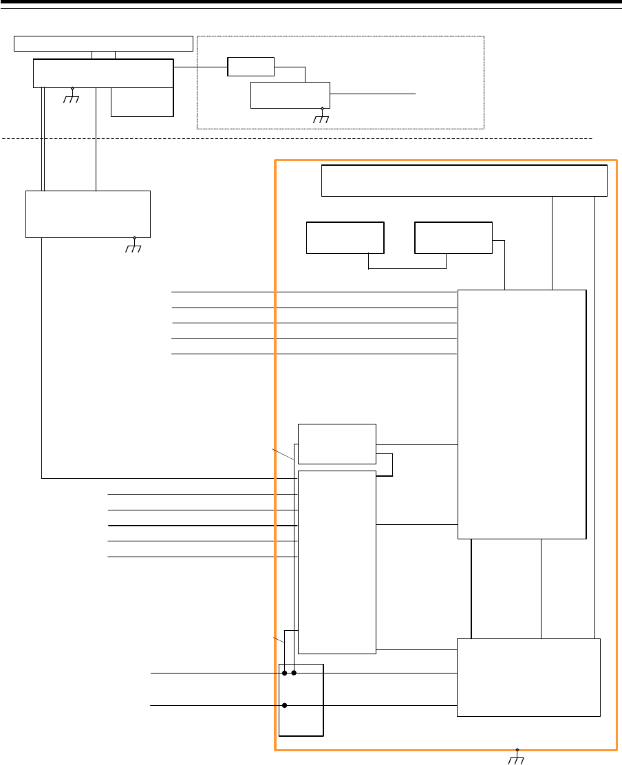
Section 1 Overview 1-48
150/250V TTYCSLA-4
AIS
(IEC61162-2)
GYRO COMPASS
(IEC61162-2)
No.1 DGPS
(IEC61162-1)
SDME
(IEC61162-1)
BNWAS
(Dry Contact)
Upper Deck
Lower Deck
NKE-1129-9
Scanner Unit
NJU-85
Performance
Monitor
2695110056 14 Cores Composite Cable
150/250V TTYCSLA-1
150/250V TTYCSLA-1
150/250V TTYCSLA-1
150/250V TTYCSLA-1
(5A)
NBL-175
Step down Transformer
1600VA
0.6/1kV DPYCYS-1.5 Ship’s Main AC 220V
For Heater
Circuit Breaker
(Dock Supply)
Option
NTG-3225
Transmitter Receiver Unit
Flexible
wave guide
FR-9
150/250V TTYCSLA-4
AIS
(IEC61162-2)
GYRO COMPASS
(IEC61162-2)
No.1 DGPS
(IEC61162-1)
SDME
(IEC61162-1)
BNWAS
(Dry Contact)
150/250V TTYCSLA-1
150/250V TTYCSLA-1
150/250V TTYCSLA-1
150/250V TTYCSLA-1
2695110056
14 Cores Composite Cable
NOTE: ELIMINATING THE INTERFERENCE ON FREQUENCIES USED FOR MARINE COMMUNICATIONS AND
NAVIGATION DUE TO OPERATION OF THE RADAR,
ALL CABLES OF THE RADAR ARE TO BE RUN AWAY FROM THE CABLES OF RADIO EQUIPMENT.
(ex. RADIOTELEPHONE, COMMUNICATIONS RECEIVER and DIRECTION FINDER. etc..)
ESPECIALLY INTER-WIRING CABLES BETWEEN SCANNER UNIT AND DISPLAY UNIT OF THE RADAR
SHOULD NOT BE RUN PARALLEL WITH THE CABLES OF RADIO EQUIPMENT.
CML-836AC
W851:7ZCNA4158(0.85m)
CML-836AC
W841:7ZCNA4164(1m)
CAT-5 LAN Cable
NQE-1143
Junction Box
(Option)
NCE-5605
Trackball Operation Unit
NBD-913
Power Supply Unit
NWZ-208
26inch Monitor Unit
CML-901
W71:7ZCNA4147(0.65m)
CML-901
W61:7ZCNA4151(0.75m)
CML-901
W73:7ZCNA4149(1.05m)
NCE-5625
Keyboard Operation Unit
(Option)
W64:7ZCNA4187(0.40m)
CWA-246 26inch Display Unit Mount Kit
CAT-5 LAN Cable
NDC-1590
Central Control Unit
CML-901
W53:7ZCNA4156A(0.55m)
CML-901
W51:7ZCNA4154(0.8m)
NQA-2443
Sensor LAN
Switch Unit
(Option)
Inner wiring
24VDC/Max2A
(For Junction Box:SLC)
Inner wiring
24VDC/Max0.4A
(For LAN Unit)
CQD-2312
Relay
Terminal
Transitional Source of
Emergency Electric Power
24VDC/Max300W
0.6/1kV DPYCYS-16
0.6/1kV DPYCY-6
Ship's Main
AC220V 1PH/Max1700VA
Inner wiring
24VDC
Inner wiring
AC220V 1PH
General System Diagram of JMR-9225-9X3

1-49 Section 1 Overview
1
2
3
4
5
6
7
8
9
10
11
12
13
14
15
16
17
18
19
20
21
22
23
24
25
26
27
付録
150/250V TTYCSLA-4
AIS
(IEC61162-2)
GYRO COMPASS
(IEC61162-2)
No.1 DGPS
(IEC61162-1)
SDME
(IEC61162-1)
BNWAS
(Dry Contact)
Upper Deck
Lower Deck
NKE-1125-6
Scanner Unit
NJU-85
Performance
Monitor
2695110056 14 Cores Composite Cable
150/250V TTYCSLA-1
150/250V TTYCSLA-1
150/250V TTYCSLA-1
150/250V TTYCSLA-1
(5A)
NBL-175
Step down Transformer
1600VA
0.6/1kV DPYCYS-1.5
Ship’s Main AC 220V
For Heater
Circuit Breaker
(Dock Supply)
Option
150/250V TTYCSLA-4
AIS
(IEC61162-2)
GYRO COMPASS
(IEC61162-2)
No.1 DGPS
(IEC61162-1)
SDME
(IEC61162-1)
BNWAS
(Dry Contact)
150/250V TTYCSLA-1
150/250V TTYCSLA-1
150/250V TTYCSLA-1
150/250V TTYCSLA-1
NOTE: ELIMINATING THE INTERFERENCE ON FREQUENCIES USED FOR MARINE COMMUNICATIONS AND
NAVIGATION DUE TO OPERATION OF THE RADAR,
ALL CABLES OF THE RADAR ARE TO BE RUN AWAY FROM THE CABLES OF RADIO EQUIPMENT.
(ex. RADIOTELEPHONE, COMMUNICATIONS RECEIVER and DIRECTION FINDER. etc..)
ESPECIALLY INTER-WIRING CABLES BETWEEN SCANNER UNIT AND DISPLAY UNIT OF THE RADAR
SHOULD NOT BE RUN PARALLEL WITH THE CABLES OF RADIO EQUIPMENT.
CML-836AC
W851:7ZCNA4158(0.85m)
CML-836AC
W841:7ZCNA4164(1m)
CAT-5 LAN Cable
NQE-1143
Junction Box
(Option)
NCE-5605
Trackball Operation Unit
NBD-913
Power Supply Unit
NWZ-208
26inch Monitor Unit
CML-901
W71:7ZCNA4147(0.65m)
CML-901
W61:7ZCNA4151(0.75m)
CML-901
W73:7ZCNA4149(1.05m)
NCE-5625
Keyboard Operation Unit
(Option)
W64:7ZCNA4187(0.40m)
CWA-246 26inch Display Unit Mount Kit
CAT-5 LAN Cable
NDC-1590
Central Control Unit
CML-901
W53:7ZCNA4156A(0.55m)
CML-901
W51:7ZCNA4154(0.8m)
NQA-2443
Sensor LAN
Switch Unit
(Option)
Inner wiring
24VDC/Max2A
(For Junction Box:SLC)
Inner wiring
24VDC/Max0.4A
(For LAN Unit)
CQD-2312
Relay
Terminal
Transitional Source of
Emergency Electric Power
24VDC/Max300W
0.6/1kV DPYCYS-16
0.6/1kV DPYCY-6
Ship's Main
AC220V 1PH/MAX1700VA
Inner wiring
24VDC
Inner wiring
AC220V 1PH
General System Diagram of JMR-9225-6X
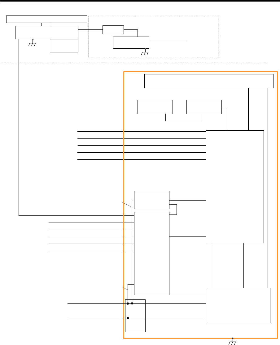
Section 1 Overview 1-50
150/250V TTYCSLA-4
AIS
(IEC61162-2)
GYRO COMPASS
(IEC61162-2)
No.1 DGPS
(IEC61162-1)
SDME
(IEC61162-1)
BNWAS
(Dry Contact)
Upper Deck
Lower Deck
NKE-1125-9
Scanner Unit
NJU-85
Performance
Monitor
2695110056 14 Cores Composite Cable
150/250V TTYCSLA-1
150/250V TTYCSLA-1
150/250V TTYCSLA-1
150/250V TTYCSLA-1
(5A)
NBL-175
Step down Transformer
1600VA
0.6/1kV DPYCYS-1.5 Ship’s Main AC 220V
For Heater
Circuit Breaker
(Dock Supply)
Option
150/250V TTYCSLA-4
AIS
(IEC61162-2)
GYRO COMPASS
(IEC61162-2)
No.1 DGPS
(IEC61162-1)
SDME
(IEC61162-1)
BNWAS
(Dry Contact)
150/250V TTYCSLA-1
150/250V TTYCSLA-1
150/250V TTYCSLA-1
150/250V TTYCSLA-1
NOTE: ELIMINATING THE INTERFERENCE ON FREQUENCIES USED FOR MARINE COMMUNICATIONS AND
NAVIGATION DUE TO OPERATION OF THE RADAR,
ALL CABLES OF THE RADAR ARE TO BE RUN AWAY FROM THE CABLES OF RADIO EQUIPMENT.
(ex. RADIOTELEPHONE, COMMUNICATIONS RECEIVER and DIRECTION FINDER. etc..)
ESPECIALLY INTER-WIRING CABLES BETWEEN SCANNER UNIT AND DISPLAY UNIT OF THE RADAR
SHOULD NOT BE RUN PARALLEL WITH THE CABLES OF RADIO EQUIPMENT.
CML-836AC
W851:7ZCNA4158(0.85m)
CML-836AC
W841:7ZCNA4164(1m)
CAT-5 LAN Cable
NQE-1143
Junction Box
(Option)
NCE-5605
Trackball Operation Unit
NBD-913
Power Supply Unit
NWZ-208
26inch Monitor Unit
CML-901
W71:7ZCNA4147(0.65m)
CML-901
W61:7ZCNA4151(0.75m)
CML-901
W73:7ZCNA4149(1.05m)
NCE-5625
Keyboard Operation Unit
(Option)
W64:7ZCNA4187(0.40m)
CWA-246 26inch Display Unit Mount Kit
CAT-5 LAN Cable
NDC-1590
Central Control Unit
CML-901
W53:7ZCNA4156A(0.55m)
CML-901
W51:7ZCNA4154(0.8m)
NQA-2443
Sensor LAN
Switch Unit
(Option)
Inner wiring
24VDC/Max2A
(For Junction Box:SLC)
Inner wiring
24VDC/Max0.4A
(For LAN Unit)
CQD-2312
Relay
Terminal
Transitional Source of
Emergency Electric Power
24VDC/Max300W
0.6/1kV DPYCYS-16
0.6/1kV DPYCY-6
Ship's Main
AC220V 1PH/Max1700VA
Inner wiring
24VDC
Inner wiring
AC220V 1PH
General System Diagram of JMR-9225-9X
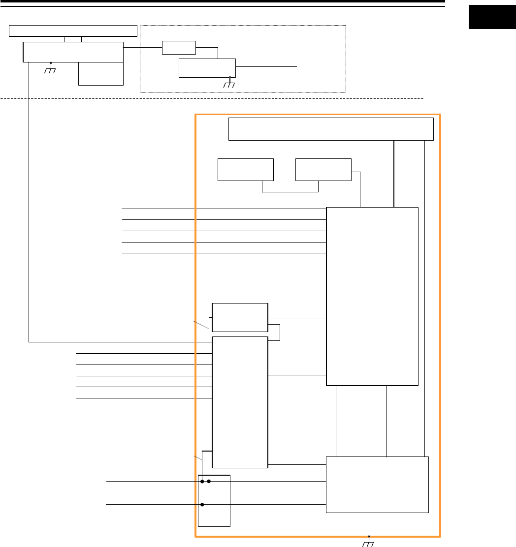
1-51 Section 1 Overview
1
2
3
4
5
6
7
8
9
10
11
12
13
14
15
16
17
18
19
20
21
22
23
24
25
26
27
付録
150/250V TTYCSLA-4
AIS
(IEC61162-2)
GYRO COMPASS
(IEC61162-2)
No.1 DGPS
(IEC61162-1)
SDME
(IEC61162-1)
BNWAS
(Dry Contact)
Upper Deck
Lower Deck
NKE-2254-6HS
Scanner Unit
NJU-85
Performance
Monitor
CFQ-6912 19 Cores Composite Cable
150/250V TTYCSLA-1
150/250V TTYCSLA-1
150/250V TTYCSLA-1
150/250V TTYCSLA-1
(5A)
NBL-175
Step down Transformer
1600VA
0.6/1kV DPYCYS-1.5
Ship’s Main AC 220V
For Heater
Circuit Breaker
(Dock Supply)
Option
150/250V TTYCSLA-4
AIS
(IEC61162-2)
GYRO COMPASS
(IEC61162-2)
No.1 DGPS
(IEC61162-1)
SDME
(IEC61162-1)
BNWAS
(Dry Contact)
150/250V TTYCSLA-1
150/250V TTYCSLA-1
150/250V TTYCSLA-1
150/250V TTYCSLA-1
NOTE: ELIMINATING THE INTERFERENCE ON FREQUENCIES USED FOR MARINE COMMUNICATIONS AND
NAVIGATION DUE TO OPERATION OF THE RADAR,
ALL CABLES OF THE RADAR ARE TO BE RUN AWAY FROM THE CABLES OF RADIO EQUIPMENT.
(ex. RADIOTELEPHONE, COMMUNICATIONS RECEIVER and DIRECTION FINDER. etc..)
ESPECIALLY INTER-WIRING CABLES BETWEEN SCANNER UNIT AND DISPLAY UNIT OF THE RADAR
SHOULD NOT BE RUN PARALLEL WITH THE CABLES OF RADIO EQUIPMENT.
CAT-5 LAN Cable
NQE-1143
Junction Box
(Option)
NCE-5605
Trackball Operation Unit
NBD-913
Power Supply Unit
NWZ-208
26inch Monitor Unit
CML-901
W71:7ZCNA4147(0.65m)
CML-901
W61:7ZCNA4151(0.75m)
CML-901
W73:7ZCNA4149(1.05m)
NCE-5625
Keyboard Operation Unit
(Option)
W64:7ZCNA4187(0.40m)
CWA-246 26inch Display Unit Mount Kit
CAT-5 LAN Cable
NDC-1590
Central Control Unit
CML-901
W53:7ZCNA4156A(0.55m)
CML-901
W51:7ZCNA4154(0.8m)
NQA-2443
Sensor LAN
Switch Unit
(Option)
Inner wiring
24VDC/Max2A
(For Junction Box:SLC)
Inner wiring
24VDC/Max0.4A
(For LAN Unit)
CQD-2312
Relay
Terminal
Transitional Source of
Emergency Electric Power
24VDC/Max660W
0.6/1kV DPYCYS-16
0.6/1kV DPYCY-6
Ship's Main
AC220V 1PH/Max240VA
Inner wiring
24VDC
Inner wiring
AC220V 1PH
CML-836DC
W853:7ZCNA4160(0.85m)
CML-836DC
W841:7ZCNA4164(1m)
General System Diagram of JMR-9225-6XH
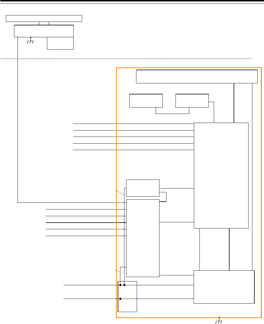
Section 1 Overview 1-52
150/250V TTYCSLA-4
AIS
(IEC61162-2)
GYRO COMPASS
(IEC61162-2)
No.1 DGPS
(IEC61162-1)
SDME
(IEC61162-1)
BNWAS
(Dry Contact)
Upper Deck
Lower Deck
NKE-2103-6
Scanner Unit
NJU-85
Performance
Monitor
CFQ-6912 19 Cores Composite Cable
150/250V TTYCSLA-1
150/250V TTYCSLA-1
150/250V TTYCSLA-1
150/250V TTYCSLA-1
150/250V TTYCSLA-4
AIS
(IEC61162-2)
GYRO COMPASS
(IEC61162-2)
No.1 DGPS
(IEC61162-1)
SDME
(IEC61162-1)
BNWAS
(Dry Contact)
150/250V TTYCSLA-1
150/250V TTYCSLA-1
150/250V TTYCSLA-1
150/250V TTYCSLA-1
NOTE: ELIMINATING THE INTERFERENCE ON FREQUENCIES USED FOR MARINE COMMUNICATIONS AND
NAVIGATION DUE TO OPERATION OF THE RADAR,
ALL CABLES OF THE RADAR ARE TO BE RUN AWAY FROM THE CABLES OF RADIO EQUIPMENT.
(ex. RADIOTELEPHONE, COMMUNICATIONS RECEIVER and DIRECTION FINDER. etc..)
ESPECIALLY INTER-WIRING CABLES BETWEEN SCANNER UNIT AND DISPLAY UNIT OF THE RADAR
SHOULD NOT BE RUN PARALLEL WITH THE CABLES OF RADIO EQUIPMENT.
CAT-5 LAN Cable
NQE-1143
Junction Box
(Option)
NCE-5605
Trackball Operation Unit
NBD-913
Power Supply Unit
NWZ-208
26inch Monitor Unit
CML-901
W71:7ZCNA4147(0.65m)
CML-901
W61:7ZCNA4151(0.75m)
CML-901
W73:7ZCNA4149(1.05m)
NCE-5625
Keyboard Operation Unit
(Option)
W64:7ZCNA4187(0.40m)
CWA-246 26inch Display Unit Mount Kit
CAT-5 LAN Cable
NDC-1590
Central Control Unit
CML-901
W53:7ZCNA4156A(0.55m)
CML-901
W51:7ZCNA4154(0.8m)
NQA-2443
Sensor LAN
Switch Unit
(Option)
Inner wiring
24VDC/Max2A
(For Junction Box:SLC)
Inner wiring
24VDC/Max0.4A
(For LAN Unit)
CQD-2312
Relay
Terminal
Transitional Source of
Emergency Electric Power
24VDC/Max510W
0.6/1kV DPYCYS-16
0.6/1kV DPYCY-6
Ship's Main
AC220V 1PH/Max240VA
Inner wiring
24VDC
Inner wiring
AC220V 1PH
CML-836DC
W853:7ZCNA4160(0.85m)
CML-836DC
W841:7ZCNA4164(1m)
General System Diagram of JMR-9210-6X
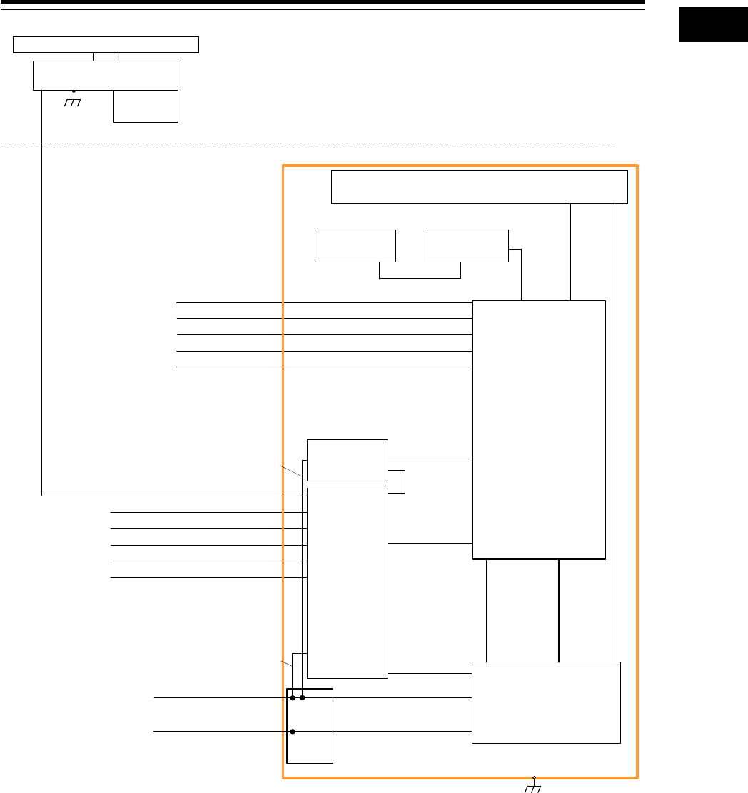
1-53 Section 1 Overview
1
2
3
4
5
6
7
8
9
10
11
12
13
14
15
16
17
18
19
20
21
22
23
24
25
26
27
付録
150/250V TTYCSLA-4
AIS
(IEC61162-2)
GYRO COMPASS
(IEC61162-2)
No.1 DGPS
(IEC61162-1)
SDME
(IEC61162-1)
BNWAS
(Dry Contact)
Upper Deck
Lower Deck
NKE-2103-6HS
Scanner Unit
NJU-85
Performance
Monitor
CFQ-6912 19 Cores Composite Cable
150/250V TTYCSLA-1
150/250V TTYCSLA-1
150/250V TTYCSLA-1
150/250V TTYCSLA-1
150/250V TTYCSLA-4
AIS
(IEC61162-2)
GYRO COMPASS
(IEC61162-2)
No.1 DGPS
(IEC61162-1)
SDME
(IEC61162-1)
BNWAS
(Dry Contact)
150/250V TTYCSLA-1
150/250V TTYCSLA-1
150/250V TTYCSLA-1
150/250V TTYCSLA-1
NOTE: ELIMINATING THE INTERFERENCE ON FREQUENCIES USED FOR MARINE COMMUNICATIONS AND
NAVIGATION DUE TO OPERATION OF THE RADAR,
ALL CABLES OF THE RADAR ARE TO BE RUN AWAY FROM THE CABLES OF RADIO EQUIPMENT.
(ex. RADIOTELEPHONE, COMMUNICATIONS RECEIVER and DIRECTION FINDER. etc..)
ESPECIALLY INTER-WIRING CABLES BETWEEN SCANNER UNIT AND DISPLAY UNIT OF THE RADAR
SHOULD NOT BE RUN PARALLEL WITH THE CABLES OF RADIO EQUIPMENT.
CAT-5 LAN Cable
NQE-1143
Junction Box
(Option)
NCE-5605
Trackball Operation Unit
NBD-913
Power Supply Unit
NWZ-208
26inch Monitor Unit
CML-901
W71:7ZCNA4147(0.65m)
CML-901
W61:7ZCNA4151(0.75m)
CML-901
W73:7ZCNA4149(1.05m)
NCE-5625
Keyboard Operation Unit
(Option)
W64:7ZCNA4187(0.40m)
CWA-246 26inch Display Unit Mount Kit
CAT-5 LAN Cable
NDC-1590
Central Control Unit
CML-901
W53:7ZCNA4156A(0.55m)
CML-901
W51:7ZCNA4154(0.8m)
NQA-2443
Sensor LAN
Switch Unit
(Option)
Inner wiring
24VDC/Max2A
(For Junction Box:SLC)
Inner wiring
24VDC/Max0.4A
(For LAN Unit)
CQD-2312
Relay
Terminal
Transitional Source of
Emergency Electric Power
24VDC/Max610W
0.6/1kV DPYCYS-16
0.6/1kV DPYCY-6
Ship's Main
AC220V 1PH/Max240VA
Inner wiring
24VDC
Inner wiring
AC220V 1PH
CML-836DC
W853:7ZCNA4160(0.85m)
CML-836DC
W841:7ZCNA4164(1m)
General System Diagram of JMR-9210-6XH
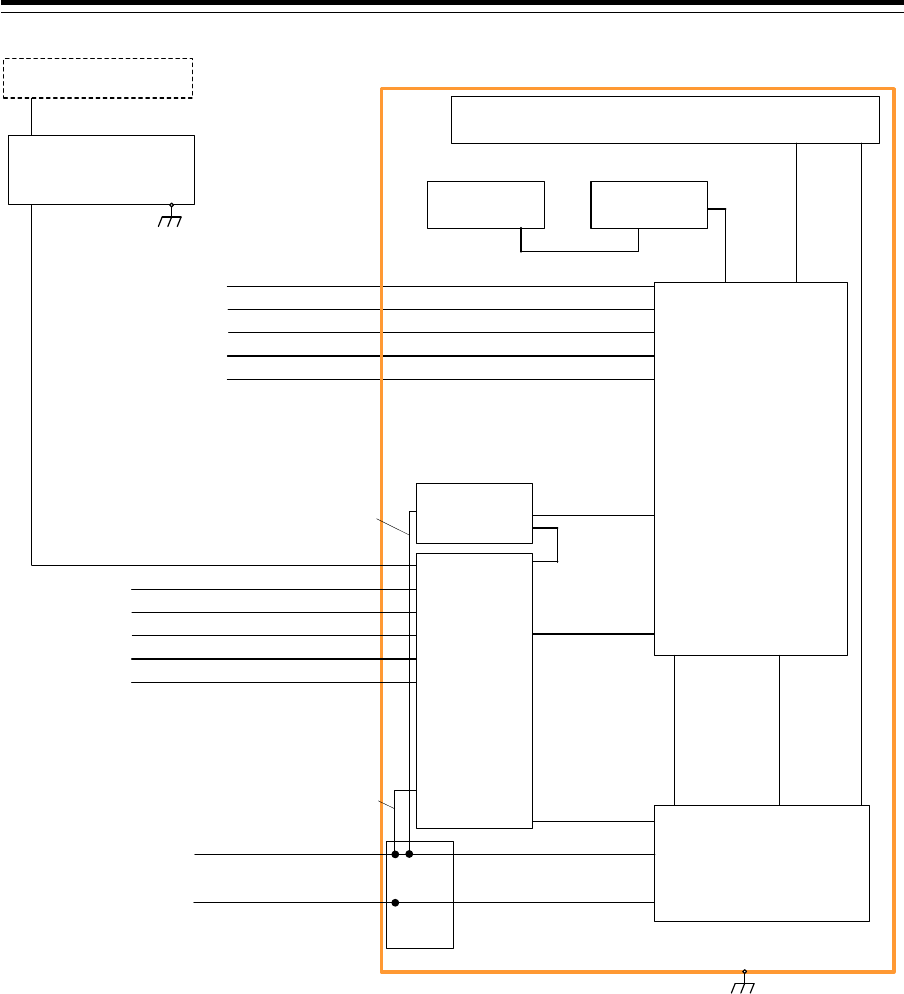
Section 1 Overview 1-54
150/250V TTYCSLA-4
AIS
(IEC61162-2)
GYRO COMPASS
(IEC61162-2)
No.1 DGPS
(IEC61162-1)
SDME
(IEC61162-1)
BNWAS
(Dry Contact)
CML-836AC
W851:7ZCNA4158(0.85m)
CML-836AC
W841:7ZCNA4164(1m)
CAT-5 LAN Cable
NQE-1143
Junction Box
(Option)
NCE-5605
Trackball Operation Unit
NBD-913
Power Supply Unit
NOTE: ELIMINATING THE INTERFERENCE ON FREQUENCIES USED FOR MARINE COMMUNICATIONS AND
NAVIGATION DUE TO OPERATION OF THE RADAR,
ALL CABLES OF THE RADAR ARE TO BE RUN AWAY FROM THE CABLES OF RADIO EQUIPMENT.
(ex. RADIOTELEPHONE, COMMUNICATIONS RECEIVER and DIRECTION FINDER. etc..)
ESPECIALLY INTER-WIRING CABLES BETWEEN SCANNER UNIT AND DISPLAY UNIT OF THE RADAR
SHOULD NOT BE RUN PARALLEL WITH THE CABLES OF RADIO EQUIPMENT.
150/250V TTYCSLA-1
150/250V TTYCSLA-1
150/250V TTYCSLA-1
150/250V TTYCSLA-1
NWZ-208
26inch Monitor Unit
(Option)
CML-901
W71:7ZCNA4147(0.65m)
CML-901
W61:7ZCNA4151(0.75m)
CML-901
W73:7ZCNA4149(1.05m)
NCE-5625
Keyboard Operation Unit
(Option)
W64:7ZCNA4187(0.40m)
CWA-246 26inch Display Unit Mount Kit
NQA-2443
Sensor LAN
Switch Unit
(Option)
150/250V TTYCSLA-4
AIS
(IEC61162-2)
GYRO COMPASS
(IEC61162-2)
No.1 DGPS
(IEC61162-1)
SDME
(IEC61162-1)
BNWAS
(Dry Contact)
150/250V TTYCSLA-1
150/250V TTYCSLA-1
150/250V TTYCSLA-1
150/250V TTYCSLA-1
CAT-5 LAN Cable
NDC-1590
Central Control Unit
CML-901
W53:7ZCNA4156A(0.55m)
CML-901
W51:7ZCNA4154(0.8m)
Inner wiring
24VDC/Max2A
(For Junction Box:SLC)
Inner wiring
24VDC/Max0.4A
(For LAN Unit)
CQD-2312
Relay
Terminal
0.6/1kV DPYCYS-16
0.6/1kV DPYCY-6
Transitional Source of
Emergency Electric Power
24VDC/Max300W
(For System Backup)
Ship's Main
AC220V 1PH/Max240VA
Inner wiring
24VDC
Inner wiring
AC220V 1PH
NQE-3141-4A/8A
Interswitch Unit
(Option)
Scanner Unit
(For Radar Overlay)
2695111153 Interswitch cable
General System Diagram of JAN-9201

1-55 Section 1 Overview
1
2
3
4
5
6
7
8
9
10
11
12
13
14
15
16
17
18
19
20
21
22
23
24
25
26
27
付録
150/250V TTYCSLA-4
AIS
(IEC61162-2)
GYRO COMPASS
(IEC61162-2)
No.1 DGPS
(IEC61162-1)
SDME
(IEC61162-1)
BNWAS
(Dry Contact)
CML-836AC
W851:7ZCNA4158(0.85m)
CML-836AC
W841:7ZCNA4164(1m)
CAT-5 LAN Cable
NQE-1143
Junction Box
(Option)
Upper Deck
Lower Deck
NKE-1139
Scanner Unit
NCE-5605
Trackball Operation Unit
NBD-913
Power Supply Unit
NJU-84
Performance
Monitor
2695110056 14 Cores Composite Cable
NOTE: ELIMINATING THE INTERFERENCE ON FREQUENCIES USED FOR MARINE COMMUNICATIONS AND
NAVIGATION DUE TO OPERATION OF THE RADAR,
ALL CABLES OF THE RADAR ARE TO BE RUN AWAY FROM THE CABLES OF RADIO EQUIPMENT.
(ex. RADIOTELEPHONE, COMMUNICATIONS RECEIVER and DIRECTION FINDER. etc..)
ESPECIALLY INTER-WIRING CABLES BETWEEN SCANNER UNIT AND DISPLAY UNIT OF THE RADAR
SHOULD NOT BE RUN PARALLEL WITH THE CABLES OF RADIO EQUIPMENT.
150/250V TTYCSLA-1
150/250V TTYCSLA-1
150/250V TTYCSLA-1
150/250V TTYCSLA-1
NWZ-207
19inch Monitor Unit
CML-901
W71:7ZCNA4147(0.65m)
CML-901
W61:7ZCNA4151(0.75m)
CML-901
W73:7ZCNA4149(1.05m)
(5A)
NBL-175
Step down Transformer
1600VA
0.6/1kV DPYCYS-1.5 Ship’s Main AC 220V
For Heater
Circuit Breaker
(Dock Supply)
Option
NTG-3230
Transmitter Receiver Unit
NCE-5625
Keyboard Operation Unit
(Option)
W64:7ZCNA4187(0.40m)
CWA-245 19inch Display Unit Mount Kit
Coaxial Cable
HF-20D
NQA-2443
Sensor LAN
Switch Unit
(Option)
150/250V TTYCSLA-4
AIS
(IEC61162-2)
GYRO COMPASS
(IEC61162-2)
No.1 DGPS
(IEC61162-1)
SDME
(IEC61162-1)
BNWAS
(Dry Contact)
150/250V TTYCSLA-1
150/250V TTYCSLA-1
150/250V TTYCSLA-1
150/250V TTYCSLA-1
2695110056
14 Cores Composite Cable
CAT-5 LAN Cable
NDC-1590
Central Control Unit
CML-901
W53:7ZCNA4156A(0.55m)
CML-901
W51:7ZCNA4154(0.8m)
Inner wiring
24VDC/Max2A
(For Junction Box:SLC)
Inner wiring
24VDC/Max 0.4A
(For LAN Unit)
CQD-2312
Relay
Terminal
Transitional Source of
Emergency Electric Power
24VDC/Max300W
0.6/1kV DPYCYS-16
0.6/1kV DPYCY-6
Ship's Main
AC220V 1PH/Max1900VA
Inner wiring
24VDC
Inner wiring
AC220V 1PH
General System Diagram of JMR-7230-S3
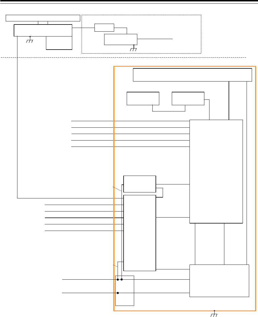
Section 1 Overview 1-56
150/250V TTYCSLA-4
AIS
(IEC61162-2)
GYRO COMPASS
(IEC61162-2)
No.1 DGPS
(IEC61162-1)
SDME
(IEC61162-1)
BNWAS
(Dry Contact)
Upper Deck
Lower Deck
NKE-1130
Scanner Unit
2695110056 14 Cores Composite Cable
150/250V TTYCSLA-1
150/250V TTYCSLA-1
150/250V TTYCSLA-1
150/250V TTYCSLA-1
(5A)
NBL-175
Step down Transformer
1600VA
0.6/1kV DPYCYS-1.5 Ship’s Main AC 220V
For Heater
Circuit Breaker
(Dock Supply)
Option
150/250V TTYCSLA-4
AIS
(IEC61162-2)
GYRO COMPASS
(IEC61162-2)
No.1 DGPS
(IEC61162-1)
SDME
(IEC61162-1)
BNWAS
(Dry Contact)
150/250V TTYCSLA-1
150/250V TTYCSLA-1
150/250V TTYCSLA-1
150/250V TTYCSLA-1
NOTE: ELIMINATING THE INTERFERENCE ON FREQUENCIES USED FOR MARINE COMMUNICATIONS AND
NAVIGATION DUE TO OPERATION OF THE RADAR,
ALL CABLES OF THE RADAR ARE TO BE RUN AWAY FROM THE CABLES OF RADIO EQUIPMENT.
(ex. RADIOTELEPHONE, COMMUNICATIONS RECEIVER and DIRECTION FINDER. etc..)
ESPECIALLY INTER-WIRING CABLES BETWEEN SCANNER UNIT AND DISPLAY UNIT OF THE RADAR
SHOULD NOT BE RUN PARALLEL WITH THE CABLES OF RADIO EQUIPMENT.
CML-836AC
W851:7ZCNA4158(0.85m)
CML-836AC
W841:7ZCNA4164(1m)
CAT-5 LAN Cable
NQE-1143
Junction Box
(Option)
NCE-5605
Trackball Operation Unit
NBD-913
Power Supply Unit
NWZ-207
19inch Monitor Unit
CML-901
W71:7ZCNA4147(0.65m)
CML-901
W61:7ZCNA4151(0.75m)
CML-901
W73:7ZCNA4149(1.05m)
NCE-5625
Keyboard Operation Unit
(Option)
W64:7ZCNA4187(0.40m)
CWA-245 19inch Display Unit Mount Kit
NQA-2443
Sensor LAN
Switch Unit
(Option)
CAT-5 LAN Cable
NDC-1590
Central Control Unit
CML-901
W53:7ZCNA4156A(0.55m)
CML-901
W51:7ZCNA4154(0.8m)
Inner wiring
24VDC/Max2A
(For Junction Box:SLC)
Inner wiring
24VDC/Max0.4A
(For LAN Unit)
CQD-2312
Relay
Terminal
Transitional Source of
Emergency Electric Power
24VDC/Max300W
0.6/1kV DPYCYS-16
0.6/1kV DPYCY-6
Ship's Main
AC220V 1PH/Max1900VA
Inner wiring
24VDC
Inner wiring
AC220V 1PH
NJU-84
Performance
Monitor
(Option)
General System Diagram of JMR-7230-S

1-57 Section 1 Overview
1
2
3
4
5
6
7
8
9
10
11
12
13
14
15
16
17
18
19
20
21
22
23
24
25
26
27
付録
150/250V TTYCSLA-4
AIS
(IEC61162-2)
GYRO COMPASS
(IEC61162-2)
No.1 DGPS
(IEC61162-1)
SDME
(IEC61162-1)
BNWAS
(Dry Contact)
Upper Deck
Lower Deck
NKE-1632
Scanner Unit
2695110056 14 Cores Composite Cable
150/250V TTYCSLA-1
150/250V TTYCSLA-1
150/250V TTYCSLA-1
150/250V TTYCSLA-1
150/250V TTYCSLA-4
AIS
(IEC61162-2)
GYRO COMPASS
(IEC61162-2)
No.1 DGPS
(IEC61162-1)
SDME
(IEC61162-1)
BNWAS
(Dry Contact)
150/250V TTYCSLA-1
150/250V TTYCSLA-1
150/250V TTYCSLA-1
150/250V TTYCSLA-1
(5A)
Circuit Breaker
(Dock Supply)
Option
0.6/1kV DPYCYS-1.5 Ship’s Main AC100V / 220V
For Heater
NOTE: ELIMINATING THE INTERFERENCE ON FREQUENCIES USED FOR MARINE COMMUNICATIONS AND
NAVIGATION DUE TO OPERATION OF THE RADAR,
ALL CABLES OF THE RADAR ARE TO BE RUN AWAY FROM THE CABLES OF RADIO EQUIPMENT.
(ex. RADIOTELEPHONE, COMMUNICATIONS RECEIVER and DIRECTION FINDER. etc..)
ESPECIALLY INTER-WIRING CABLES BETWEEN SCANNER UNIT AND DISPLAY UNIT OF THE RADAR
SHOULD NOT BE RUN PARALLEL WITH THE CABLES OF RADIO EQUIPMENT.
CML-836AC
W851:7ZCNA4158(0.85m)
CML-836AC
W841:7ZCNA4164(1m)
CAT-5 LAN Cable
NQE-1143
Junction Box
(Option)
NCE-5605
Trackball Operation Unit
NBD-913
Power Supply Unit
NWZ-207
19inch Monitor Unit
CML-901
W71:7ZCNA4147(0.65m)
CML-901
W61:7ZCNA4151(0.75m)
CML-901
W73:7ZCNA4149(1.05m)
NCE-5625
Keyboard Operation Unit
(Option)
W64:7ZCNA4187(0.40m)
CWA-245 19inch Display Unit Mount Kit
NQA-2443
Sensor LAN
Switch Unit
(Option)
CAT-5 LAN Cable
NDC-1590
Central Control Unit
CML-901
W53:7ZCNA4156A(0.55m)
CML-901
W51:7ZCNA4154(0.8m)
Inner wiring
24VDC/Max2A
(For Junction Box:SLC)
Inner wiring
24VDC/Max0.4A
(For LAN Unit)
CQD-2312
Relay
Terminal
Transitional Source of
Emergency Electric Power
24VDC/Max300W
0.6/1kV DPYCYS-16
0.6/1kV DPYCY-6
Ship's Main
AC220V 1PH/Max1800VA
Inner wiring
24VDC
Inner wiring
AC220V 1PH
General System Diagram of JMR-7272-S
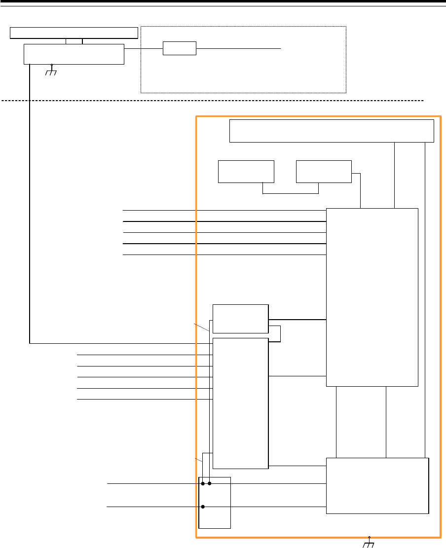
Section 1 Overview 1-58
150/250V TTYCSLA-4
AIS
(IEC61162-2)
GYRO COMPASS
(IEC61162-2)
No.1 DGPS
(IEC61162-1)
SDME
(IEC61162-1)
BNWAS
(Dry Contact)
Upper Deck
Lower Deck
NKE-2632
Scanner Unit
2695110056 14 Cores Composite Cable
150/250V TTYCSLA-1
150/250V TTYCSLA-1
150/250V TTYCSLA-1
150/250V TTYCSLA-1
150/250V TTYCSLA-4
AIS
(IEC61162-2)
GYRO COMPASS
(IEC61162-2)
No.1 DGPS
(IEC61162-1)
SDME
(IEC61162-1)
BNWAS
(Dry Contact)
150/250V TTYCSLA-1
150/250V TTYCSLA-1
150/250V TTYCSLA-1
150/250V TTYCSLA-1
(5A)
Circuit Breaker
(Dock Supply)
Option
0.6/1kV DPYCYS-1.5 Ship’s Main AC100V / 220V
For Heater
NOTE: ELIMINATING THE INTERFERENCE ON FREQUENCIES USED FOR MARINE COMMUNICATIONS AND
NAVIGATION DUE TO OPERATION OF THE RADAR,
ALL CABLES OF THE RADAR ARE TO BE RUN AWAY FROM THE CABLES OF RADIO EQUIPMENT.
(ex. RADIOTELEPHONE, COMMUNICATIONS RECEIVER and DIRECTION FINDER. etc..)
ESPECIALLY INTER-WIRING CABLES BETWEEN SCANNER UNIT AND DISPLAY UNIT OF THE RADAR
SHOULD NOT BE RUN PARALLEL WITH THE CABLES OF RADIO EQUIPMENT.
CML-836AC
W851:7ZCNA4158(0.85m)
CML-836AC
W841:7ZCNA4164(1m)
CAT-5 LAN Cable
NQE-1143
Junction Box
(Option)
NCE-5605
Trackball Operation Unit
NBD-913
Power Supply Unit
NWZ-207
19inch Monitor Unit
CML-901
W71:7ZCNA4147(0.65m)
CML-901
W61:7ZCNA4151(0.75m)
CML-901
W73:7ZCNA4149(1.05m)
NCE-5625
Keyboard Operation Unit
(Option)
W64:7ZCNA4187(0.40m)
CWA-245 19inch Display Unit Mount Kit
NQA-2443
Sensor LAN
Switch Unit
(Option)
CAT-5 LAN Cable
NDC-1590
Central Control Unit
CML-901
W53:7ZCNA4156A(0.55m)
CML-901
W51:7ZCNA4154(0.8m)
Inner wiring
24VDC/Max2A
(For Junction Box:SLC)
Inner wiring
24VDC/Max0.4A
(For LAN Unit)
CQD-2312
Relay
Terminal
Transitional Source of
Emergency Electric Power
24VDC/Max300W
0.6/1kV DPYCYS-16
0.6/1kV DPYCY-6
Ship's Main
AC220V 1PH/Max1400VA
Inner wiring
24VDC
Inner wiring
AC220V 1PH
General System Diagram of JMR-7282-S
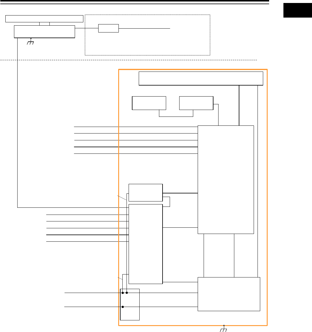
1-59 Section 1 Overview
1
2
3
4
5
6
7
8
9
10
11
12
13
14
15
16
17
18
19
20
21
22
23
24
25
26
27
付録
150/250V TTYCSLA-4
AIS
(IEC61162-2)
GYRO COMPASS
(IEC61162-2)
No.1 DGPS
(IEC61162-1)
SDME
(IEC61162-1)
BNWAS
(Dry Contact)
Upper Deck
Lower Deck
NKE-2632-H
Scanner Unit
2695110056 14 Cores Composite Cable
150/250V TTYCSLA-1
150/250V TTYCSLA-1
150/250V TTYCSLA-1
150/250V TTYCSLA-1
Inner wiring
24VDC/Max2A
(For Junction Box:SLC)
Inner wiring
24VDC/Max0.4A
(For LAN Unit)
150/250V TTYCSLA-4
AIS
(IEC61162-2)
GYRO COMPASS
(IEC61162-2)
No.1 DGPS
(IEC61162-1)
SDME
(IEC61162-1)
BNWAS
(Dry Contact)
150/250V TTYCSLA-1
150/250V TTYCSLA-1
150/250V TTYCSLA-1
150/250V TTYCSLA-1
(5A)
Circuit Breaker
(Dock Supply)
Option
0.6/1kV DPYCYS-1.5 Ship’s Main AC100V / 220V
For Heater
NOTE: ELIMINATING THE INTERFERENCE ON FREQUENCIES USED FOR MARINE COMMUNICATIONS AND
NAVIGATION DUE TO OPERATION OF THE RADAR,
ALL CABLES OF THE RADAR ARE TO BE RUN AWAY FROM THE CABLES OF RADIO EQUIPMENT.
(ex. RADIOTELEPHONE, COMMUNICATIONS RECEIVER and DIRECTION FINDER. etc..)
ESPECIALLY INTER-WIRING CABLES BETWEEN SCANNER UNIT AND DISPLAY UNIT OF THE RADAR
SHOULD NOT BE RUN PARALLEL WITH THE CABLES OF RADIO EQUIPMENT.
CML-836AC
W851:7ZCNA4158(0.85m)
CML-836AC
W841:7ZCNA4164(1m)
CAT-5 LAN Cable
NQE-1143
Junction Box
(Option)
NCE-5605
Trackball Operation Unit
NBD-913
Power Supply Unit
NWZ-207
19inch Monitor Unit
CML-901
W71:7ZCNA4147(0.65m)
CML-901
W61:7ZCNA4151(0.75m)
CML-901
W73:7ZCNA4149(1.05m)
NCE-5625
Keyboard Operation Unit
(Option)
W64:7ZCNA4187(0.40m)
CWA-245 19inch Display Unit Mount Kit
NQA-2443
Sensor LAN
Switch Unit
(Option)
CAT-5 LAN Cable
NDC-1590
Central Control Unit
CML-901
W53:7ZCNA4156A(0.55m)
CML-901
W51:7ZCNA4154(0.8m)
CQD-2312
Relay
Terminal
Transitional Source of
Emergency Electric Power
24VDC/Max300W
0.6/1kV DPYCYS-16
0.6/1kV DPYCY-6
Ship's Main
AC220V 1PH/Max1800VA
Inner wiring
24VDC
Inner wiring
AC220V 1PH
General System Diagram of JMR-7282-SH
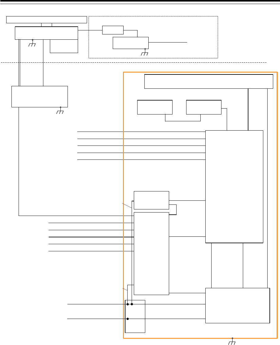
Section 1 Overview 1-60
150/250V TTYCSLA-4
AIS
(IEC61162-2)
GYRO COMPASS
(IEC61162-2)
No.1 DGPS
(IEC61162-1)
SDME
(IEC61162-1)
BNWAS
(Dry Contact)
Upper Deck
Lower Deck
NKE-1129-7
Scanner Unit
NJU-85
Performance
Monitor
2695110056 14 Cores Composite Cable
150/250V TTYCSLA-1
150/250V TTYCSLA-1
150/250V TTYCSLA-1
150/250V TTYCSLA-1
(5A)
NBL-175
Step down Transformer
1600VA
0.6/1kV DPYCYS-1.5
Ship’s Main AC 220V
For Heater
Circuit Breaker
(Dock Supply)
Option
NTG-3225
Transmitter Receiver Unit
Flexible
wave guide
FR-9
150/250V TTYCSLA-4
AIS
(IEC61162-2)
GYRO COMPASS
(IEC61162-2)
No.1 DGPS
(IEC61162-1)
SDME
(IEC61162-1)
BNWAS
(Dry Contact)
150/250V TTYCSLA-1
150/250V TTYCSLA-1
150/250V TTYCSLA-1
150/250V TTYCSLA-1
2695110056
14 Cores Composite Cable
NOTE: ELIMINATING THE INTERFERENCE ON FREQUENCIES USED FOR MARINE COMMUNICATIONS AND
NAVIGATION DUE TO OPERATION OF THE RADAR,
ALL CABLES OF THE RADAR ARE TO BE RUN AWAY FROM THE CABLES OF RADIO EQUIPMENT.
(ex. RADIOTELEPHONE, COMMUNICATIONS RECEIVER and DIRECTION FINDER. etc..)
ESPECIALLY INTER-WIRING CABLES BETWEEN SCANNER UNIT AND DISPLAY UNIT OF THE RADAR
SHOULD NOT BE RUN PARALLEL WITH THE CABLES OF RADIO EQUIPMENT.
CML-836AC
W851:7ZCNA4158(0.85m)
CML-836AC
W841:7ZCNA4164(1m)
CAT-5 LAN Cable
NQE-1143
Junction Box
(Option)
NCE-5605
Trackball Operation Unit
NBD-913
Power Supply Unit
NWZ-207
19inch Monitor Unit
CML-901
W71:7ZCNA4147(0.65m)
CML-901
W61:7ZCNA4151(0.75m)
CML-901
W73:7ZCNA4149(1.05m)
NCE-5625
Keyboard Operation Unit
(Option)
W64:7ZCNA4187(0.40m)
CWA-245 19inch Display Unit Mount Kit
NQA-2443
Sensor LAN
Switch Unit
(Option)
CAT-5 LAN Cable
NDC-1590
Central Control Unit
CML-901
W53:7ZCNA4156A(0.55m)
CML-901
W51:7ZCNA4154(0.8m)
Inner wiring
24VDC/Max2A
(For Junction Box:SLC)
Inner wiring
24VDC/Max0.4A
(For LAN Unit)
CQD-2312
Relay
Terminal
Transitional Source of
Emergency Electric Power
24VDC/Max300W
0.6/1kV DPYCYS-16
0.6/1kV DPYCY-6
Ship's Main
AC220V 1PH/Max1700VA
Inner wiring
24VDC
Inner wiring
AC220V 1PH
General System Diagram of JMR-7225-7X3

1-61 Section 1 Overview
1
2
3
4
5
6
7
8
9
10
11
12
13
14
15
16
17
18
19
20
21
22
23
24
25
26
27
付録
150/250V TTYCSLA-4
AIS
(IEC61162-2)
GYRO COMPASS
(IEC61162-2)
No.1 DGPS
(IEC61162-1)
SDME
(IEC61162-1)
BNWAS
(Dry Contact)
Upper Deck
Lower Deck
NKE-1129-9
Scanner Unit
NJU-85
Performance
Monitor
2695110056 14 Cores Composite Cable
150/250V TTYCSLA-1
150/250V TTYCSLA-1
150/250V TTYCSLA-1
150/250V TTYCSLA-1
(5A)
NBL-175
Step down Transformer
1600VA
0.6/1kV DPYCYS-1.5 Ship’s Main AC 220V
For Heater
Circuit Breaker
(Dock Supply)
Option
NTG-3225
Transmitter Receiver Unit
Flexible
wave guide
FR-9
150/250V TTYCSLA-4
AIS
(IEC61162-2)
GYRO COMPASS
(IEC61162-2)
No.1 DGPS
(IEC61162-1)
SDME
(IEC61162-1)
BNWAS
(Dry Contact)
150/250V TTYCSLA-1
150/250V TTYCSLA-1
150/250V TTYCSLA-1
150/250V TTYCSLA-1
2695110056
14 Cores Composite Cable
NOTE: ELIMINATING THE INTERFERENCE ON FREQUENCIES USED FOR MARINE COMMUNICATIONS AND
NAVIGATION DUE TO OPERATION OF THE RADAR,
ALL CABLES OF THE RADAR ARE TO BE RUN AWAY FROM THE CABLES OF RADIO EQUIPMENT.
(ex. RADIOTELEPHONE, COMMUNICATIONS RECEIVER and DIRECTION FINDER. etc..)
ESPECIALLY INTER-WIRING CABLES BETWEEN SCANNER UNIT AND DISPLAY UNIT OF THE RADAR
SHOULD NOT BE RUN PARALLEL WITH THE CABLES OF RADIO EQUIPMENT.
CML-836AC
W851:7ZCNA4158(0.85m)
CML-836AC
W841:7ZCNA4164(1m)
CAT-5 LAN Cable
NQE-1143
Junction Box
(Option)
NCE-5605
Trackball Operation Unit
NBD-913
Power Supply Unit
NWZ-207
19inch Monitor Unit
CML-901
W71:7ZCNA4147(0.65m)
CML-901
W61:7ZCNA4151(0.75m)
CML-901
W73:7ZCNA4149(1.05m)
NCE-5625
Keyboard Operation Unit
(Option)
W64:7ZCNA4187(0.40m)
CWA-245 19inch Display Unit Mount Kit
NQA-2443
Sensor LAN
Switch Unit
(Option)
CAT-5 LAN Cable
NDC-1590
Central Control Unit
CML-901
W53:7ZCNA4156A(0.55m)
CML-901
W51:7ZCNA4154(0.8m)
Inner wiring
24VDC/Max2A
(For Junction Box:SLC)
Inner wiring
24VDC/Max0.4A
(For LAN Unit)
CQD-2312
Relay
Terminal
Transitional Source of
Emergency Electric Power
24VDC/Max300W
0.6/1kV DPYCYS-16
0.6/1kV DPYCY-6
Ship's Main
AC220V 1PH/Max1700VA
Inner wiring
24VDC
Inner wiring
AC220V 1PH
General System Diagram of JMR-7225-9X3

Section 1 Overview 1-62
150/250V TTYCSLA-4
AIS
(IEC61162-2)
GYRO COMPASS
(IEC61162-2)
No.1 DGPS
(IEC61162-1)
SDME
(IEC61162-1)
BNWAS
(Dry Contact)
Upper Deck
Lower Deck
NKE-1125-6
Scanner Unit
NJU-85
Performance
Monitor
2695110056 14 Cores Composite Cable
150/250V TTYCSLA-1
150/250V TTYCSLA-1
150/250V TTYCSLA-1
150/250V TTYCSLA-1
(5A)
NBL-175
Step down Transformer
1600VA
0.6/1kV DPYCYS-1.5
Ship’s Main AC 220V
For Heater
Circuit Breaker
(Dock Supply)
Option
150/250V TTYCSLA-4
AIS
(IEC61162-2)
GYRO COMPASS
(IEC61162-2)
No.1 DGPS
(IEC61162-1)
SDME
(IEC61162-1)
BNWAS
(Dry Contact)
150/250V TTYCSLA-1
150/250V TTYCSLA-1
150/250V TTYCSLA-1
150/250V TTYCSLA-1
NOTE: ELIMINATING THE INTERFERENCE ON FREQUENCIES USED FOR MARINE COMMUNICATIONS AND
NAVIGATION DUE TO OPERATION OF THE RADAR,
ALL CABLES OF THE RADAR ARE TO BE RUN AWAY FROM THE CABLES OF RADIO EQUIPMENT.
(ex. RADIOTELEPHONE, COMMUNICATIONS RECEIVER and DIRECTION FINDER. etc..)
ESPECIALLY INTER-WIRING CABLES BETWEEN SCANNER UNIT AND DISPLAY UNIT OF THE RADAR
SHOULD NOT BE RUN PARALLEL WITH THE CABLES OF RADIO EQUIPMENT.
CML-836AC
W851:7ZCNA4158(0.85m)
CML-836AC
W841:7ZCNA4164(1m)
CAT-5 LAN Cable
NQE-1143
Junction Box
(Option)
NCE-5605
Trackball Operation Unit
NBD-913
Power Supply Unit
NWZ-207
19inch Monitor Unit
CML-901
W71:7ZCNA4147(0.65m)
CML-901
W61:7ZCNA4151(0.75m)
CML-901
W73:7ZCNA4149(1.05m)
NCE-5625
Keyboard Operation Unit
(Option)
W64:7ZCNA4187(0.40m)
CWA-245 19inch Display Unit Mount Kit
NQA-2443
Sensor LAN
Switch Unit
(Option)
CAT-5 LAN Cable
NDC-1590
Central Control Unit
CML-901
W53:7ZCNA4156A(0.55m)
CML-901
W51:7ZCNA4154(0.8m)
Inner wiring
24VDC/Max2A
(For Junction Box:SLC)
Inner wiring
24VDC/Max0.4A
(For LAN Unit)
CQD-2312
Relay
Terminal
Transitional Source of
Emergency Electric Power
24VDC/Max300W
0.6/1kV DPYCYS-16
0.6/1kV DPYCY-6
Ship's Main
AC220V 1PH/Max1700VA
Inner wiring
24VDC
Inner wiring
AC220V 1PH
General System Diagram of JMR-7225-6X
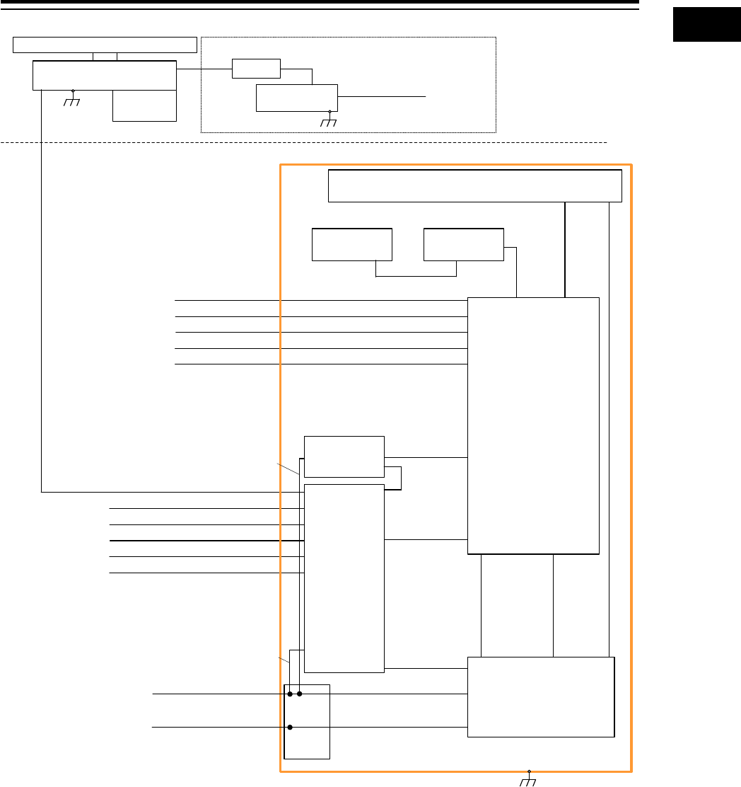
1-63 Section 1 Overview
1
2
3
4
5
6
7
8
9
10
11
12
13
14
15
16
17
18
19
20
21
22
23
24
25
26
27
付録
150/250V TTYCSLA-4
AIS
(IEC61162-2)
GYRO COMPASS
(IEC61162-2)
No.1 DGPS
(IEC61162-1)
SDME
(IEC61162-1)
BNWAS
(Dry Contact)
Upper Deck
Lower Deck
NKE-1125-9
Scanner Unit
NJU-85
Performance
Monitor
2695110056 14 Cores Composite Cable
150/250V TTYCSLA-1
150/250V TTYCSLA-1
150/250V TTYCSLA-1
150/250V TTYCSLA-1
(5A)
NBL-175
Step down Transformer
1600VA
0.6/1kV DPYCYS-1.5
Ship’s Main AC 220V
For Heater
Circuit Breaker
(Dock Supply)
Option
150/250V TTYCSLA-4
AIS
(IEC61162-2)
GYRO COMPASS
(IEC61162-2)
No.1 DGPS
(IEC61162-1)
SDME
(IEC61162-1)
BNWAS
(Dry Contact)
150/250V TTYCSLA-1
150/250V TTYCSLA-1
150/250V TTYCSLA-1
150/250V TTYCSLA-1
NOTE: ELIMINATING THE INTERFERENCE ON FREQUENCIES USED FOR MARINE COMMUNICATIONS AND
NAVIGATION DUE TO OPERATION OF THE RADAR,
ALL CABLES OF THE RADAR ARE TO BE RUN AWAY FROM THE CABLES OF RADIO EQUIPMENT.
(ex. RADIOTELEPHONE, COMMUNICATIONS RECEIVER and DIRECTION FINDER. etc..)
ESPECIALLY INTER-WIRING CABLES BETWEEN SCANNER UNIT AND DISPLAY UNIT OF THE RADAR
SHOULD NOT BE RUN PARALLEL WITH THE CABLES OF RADIO EQUIPMENT.
CML-836AC
W851:7ZCNA4158(0.85m)
CML-836AC
W841:7ZCNA4164(1m)
CAT-5 LAN Cable
NQE-1143
Junction Box
(Option)
NCE-5605
Trackball Operation Unit
NBD-913
Power Supply Unit
NWZ-207
19inch Monitor Unit
CML-901
W71:7ZCNA4147(0.65m)
CML-901
W61:7ZCNA4151(0.75m)
CML-901
W73:7ZCNA4149(1.05m)
NCE-5625
Keyboard Operation Unit
(Option)
W64:7ZCNA4187(0.40m)
CWA-245 19inch Display Unit Mount Kit
NQA-2443
Sensor LAN
Switch Unit
(Option)
CAT-5 LAN Cable
NDC-1590
Central Control Unit
CML-901
W53:7ZCNA4156A(0.55m)
CML-901
W51:7ZCNA4154(0.8m)
Inner wiring
24VDC/Max2A
(For Junction Box:SLC)
Inner wiring
24VDC/Max0.4A
(For LAN Unit)
CQD-2312
Relay
Terminal
Transitional Source of
Emergency Electric Power
24VDC/Max300W
0.6/1kV DPYCYS-16
0.6/1kV DPYCY-6
Ship's Main
AC220V 1PH/Max1700VA
Inner wiring
24VDC
Inner wiring
AC220V 1PH
General System Diagram of JMR-7225-9X
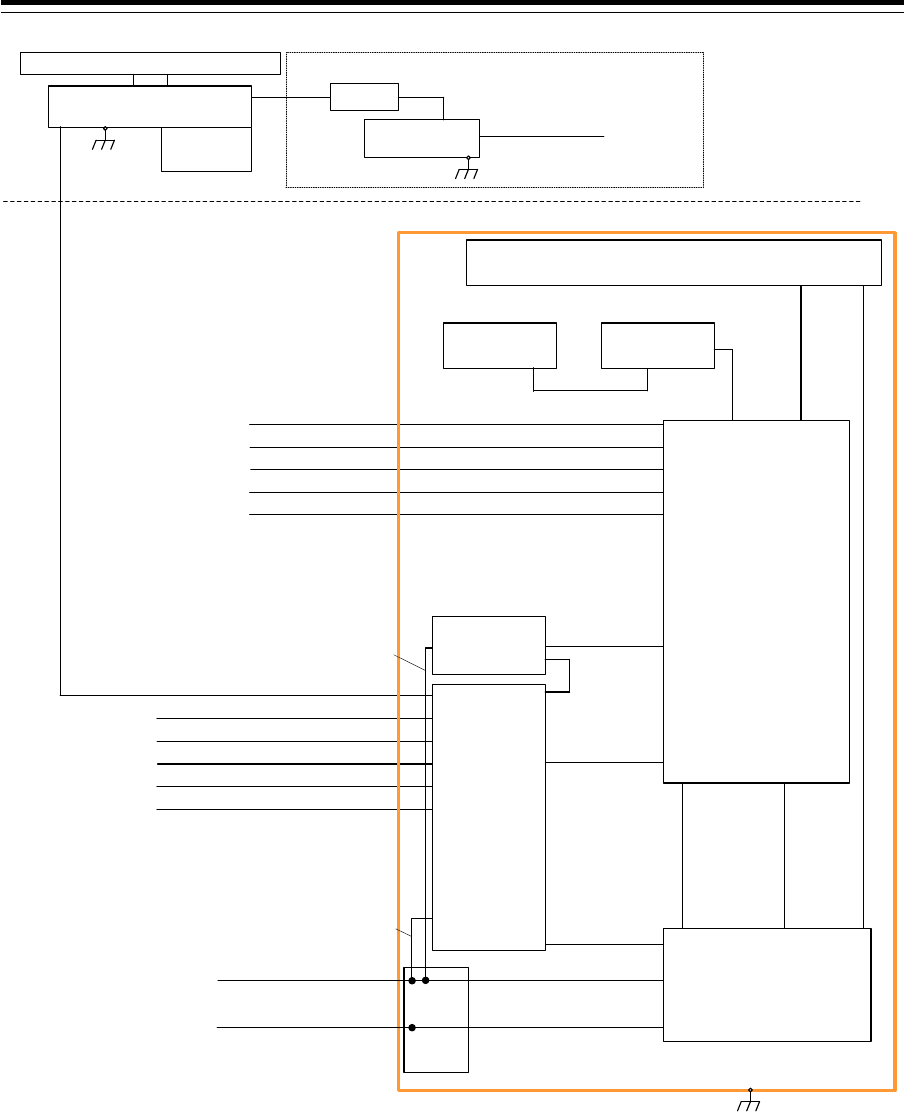
Section 1 Overview 1-64
150/250V TTYCSLA-4
AIS
(IEC61162-2)
GYRO COMPASS
(IEC61162-2)
No.1 DGPS
(IEC61162-1)
SDME
(IEC61162-1)
BNWAS
(Dry Contact)
Upper Deck
Lower Deck
NKE-2254-6HS
Scanner Unit
NJU-85
Performance
Monitor
CFQ-6912 19 Cores Composite Cable
150/250V TTYCSLA-1
150/250V TTYCSLA-1
150/250V TTYCSLA-1
150/250V TTYCSLA-1
(5A)
NBL-175
Step down Transformer
1600VA
0.6/1kV DPYCYS-1.5
Ship’s Main AC 220V
For Heater
Circuit Breaker
(Dock Supply)
Option
150/250V TTYCSLA-4
AIS
(IEC61162-2)
GYRO COMPASS
(IEC61162-2)
No.1 DGPS
(IEC61162-1)
SDME
(IEC61162-1)
BNWAS
(Dry Contact)
150/250V TTYCSLA-1
150/250V TTYCSLA-1
150/250V TTYCSLA-1
150/250V TTYCSLA-1
NOTE: ELIMINATING THE INTERFERENCE ON FREQUENCIES USED FOR MARINE COMMUNICATIONS AND
NAVIGATION DUE TO OPERATION OF THE RADAR,
ALL CABLES OF THE RADAR ARE TO BE RUN AWAY FROM THE CABLES OF RADIO EQUIPMENT.
(ex. RADIOTELEPHONE, COMMUNICATIONS RECEIVER and DIRECTION FINDER. etc..)
ESPECIALLY INTER-WIRING CABLES BETWEEN SCANNER UNIT AND DISPLAY UNIT OF THE RADAR
SHOULD NOT BE RUN PARALLEL WITH THE CABLES OF RADIO EQUIPMENT.
CML-836DC
W853:7ZCNA4160(0.85m)
CML-836DC
W841:7ZCNA4164(1m)
CAT-5 LAN Cable
NQE-1143
Junction Box
(Option)
NCE-5605
Trackball Operation Unit
NBD-913
Power Supply Unit
NWZ-207
19inch Monitor Unit
CML-901
W71:7ZCNA4147(0.65m)
CML-901
W61:7ZCNA4151(0.75m)
CML-901
W73:7ZCNA4149(1.05m)
NCE-5625
Keyboard Operation Unit
(Option)
W64:7ZCNA4187(0.40m)
CWA-245 19inch Display Unit Mount Kit
NQA-2443
Sensor LAN
Switch Unit
(Option)
CAT-5 LAN Cable
NDC-1590
Central Control Unit
CML-901
W53:7ZCNA4156A(0.55m)
CML-901
W51:7ZCNA4154(0.8m)
Inner wiring
24VDC/Max2A
(For Junction Box:SLC)
Inner wiring
24VDC/Max0.4A
(For LAN Unit)
CQD-2312
Relay
Terminal
Transitional Source of
Emergency Electric Power
24VDC/Max610W
0.6/1kV DPYCYS-16
0.6/1kV DPYCY-6
Ship's Main
AC220V 1PH/Max240VA
Inner wiring
24VDC
Inner wiring
AC220V 1PH
General System Diagram of JMR-7225-6XH
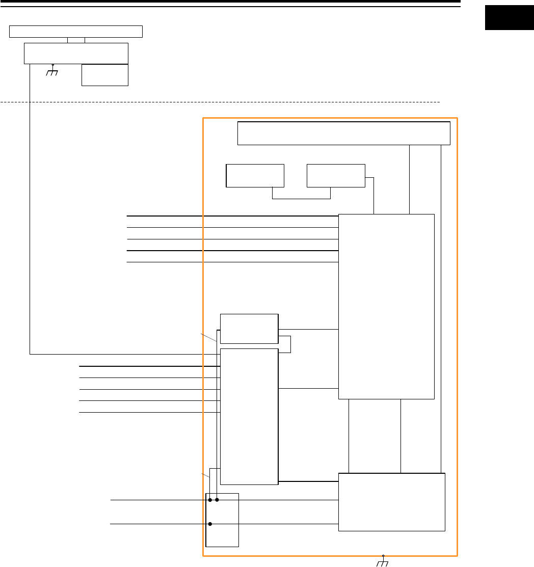
1-65 Section 1 Overview
1
2
3
4
5
6
7
8
9
10
11
12
13
14
15
16
17
18
19
20
21
22
23
24
25
26
27
付録
150/250V TTYCSLA-4
AIS
(IEC61162-2)
GYRO COMPASS
(IEC61162-2)
No.1 DGPS
(IEC61162-1)
SDME
(IEC61162-1)
BNWAS
(Dry Contact)
Upper Deck
Lower Deck
NKE-2103-6
Scanner Unit
NJU-85
Performance
Monitor
CFQ-6912 19 Cores Composite Cable
150/250V TTYCSLA-1
150/250V TTYCSLA-1
150/250V TTYCSLA-1
150/250V TTYCSLA-1
150/250V TTYCSLA-4
AIS
(IEC61162-2)
GYRO COMPASS
(IEC61162-2)
No.1 DGPS
(IEC61162-1)
SDME
(IEC61162-1)
BNWAS
(Dry Contact)
150/250V TTYCSLA-1
150/250V TTYCSLA-1
150/250V TTYCSLA-1
150/250V TTYCSLA-1
NOTE: ELIMINATING THE INTERFERENCE ON FREQUENCIES USED FOR MARINE COMMUNICATIONS AND
NAVIGATION DUE TO OPERATION OF THE RADAR,
ALL CABLES OF THE RADAR ARE TO BE RUN AWAY FROM THE CABLES OF RADIO EQUIPMENT.
(ex. RADIOTELEPHONE, COMMUNICATIONS RECEIVER and DIRECTION FINDER. etc..)
ESPECIALLY INTER-WIRING CABLES BETWEEN SCANNER UNIT AND DISPLAY UNIT OF THE RADAR
SHOULD NOT BE RUN PARALLEL WITH THE CABLES OF RADIO EQUIPMENT.
CAT-5 LAN Cable
NQE-1143
Junction Box
(Option)
NCE-5605
Trackball Operation Unit
NBD-913
Power Supply Unit
NWZ-207
19inch Monitor Unit
CML-901
W71:7ZCNA4147(0.65m)
CML-901
W61:7ZCNA4151(0.75m)
CML-901
W73:7ZCNA4149(1.05m)
NCE-5625
Keyboard Operation Unit
(Option)
W64:7ZCNA4187(0.40m)
CWA-245 19inch Display Unit Mount Kit
NQA-2443
Sensor LAN
Switch Unit
(Option)
CAT-5 LAN Cable
NDC-1590
Central Control Unit
CML-901
W53:7ZCNA4156A(0.55m)
CML-901
W51:7ZCNA4154(0.8m)
Inner wiring
24VDC/Max2A
(For Junction Box:SLC)
Inner wiring
24VDC/Max0.4A
(For LAN Unit)
CQD-2312
Relay
Terminal
Transitional Source of
Emergency Electric Power
24VDC/Max460W
0.6/1kV DPYCYS-16
0.6/1kV DPYCY-6
Ship's Main
AC220V 1PH/Max240VA
Inner wiring
24VDC
Inner wiring
AC220V 1PH
CML-836DC
W853:7ZCNA4160(0.85m)
CML-836DC
W841:7ZCNA4164(1m)
General System Diagram of JMR-7210-6X
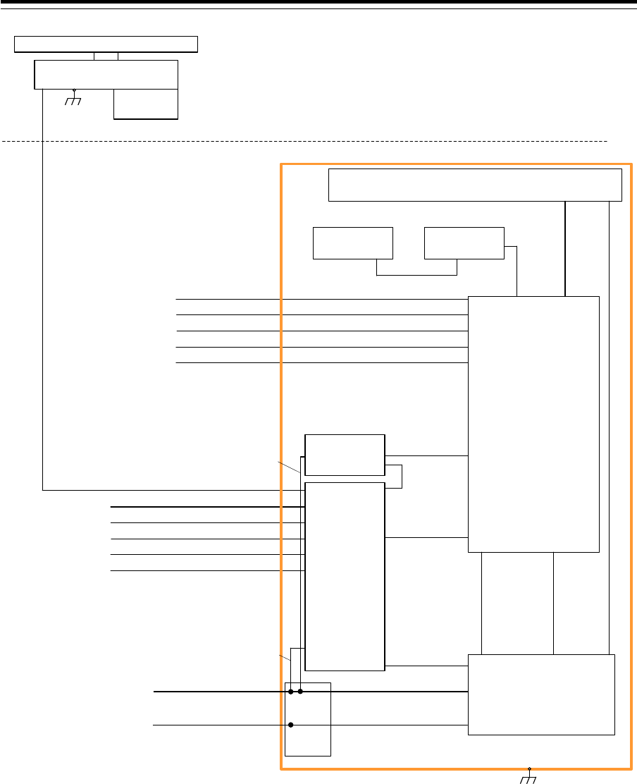
Section 1 Overview 1-66
150/250V TTYCSLA-4
AIS
(IEC61162-2)
GYRO COMPASS
(IEC61162-2)
No.1 DGPS
(IEC61162-1)
SDME
(IEC61162-1)
BNWAS
(Dry Contact)
Upper Deck
Lower Deck
NKE-2103-6HS
Scanner Unit
NJU-85
Performance
Monitor
CFQ-6912 19 Cores Composit Cable
150/250V TTYCSLA-1
150/250V TTYCSLA-1
150/250V TTYCSLA-1
150/250V TTYCSLA-1
150/250V TTYCSLA-4
AIS
(IEC61162-2)
GYRO COMPASS
(IEC61162-2)
No.1 DGPS
(IEC61162-1)
SDME
(IEC61162-1)
BNWAS
(Dry Contact)
150/250V TTYCSLA-1
150/250V TTYCSLA-1
150/250V TTYCSLA-1
150/250V TTYCSLA-1
NOTE: ELIMINATING THE INTERFERENCE ON FREQUENCIES USED FOR MARINE COMMUNICATIONS AND
NAVIGATION DUE TO OPERATION OF THE RADAR,
ALL CABLES OF THE RADAR ARE TO BE RUN AWAY FROM THE CABLES OF RADIO EQUIPMENT.
(ex. RADIOTELEPHONE, COMMUNICATIONS RECEIVER and DIRECTION FINDER. etc..)
ESPECIALLY INTER-WIRING CABLES BETWEEN SCANNER UNIT AND DISPLAY UNIT OF THE RADAR
SHOULD NOT BE RUN PARALLEL WITH THE CABLES OF RADIO EQUIPMENT.
CAT-5 LAN Cable
NQE-1143
Junction Box
(Option)
NCE-5605
Trackball Operation Unit
NBD-913
Power Supply Unit
NWZ-207
19inch Monitor Unit
CML-901
W71:7ZCNA4147(0.65m)
CML-901
W61:7ZCNA4151(0.75m)
CML-901
W73:7ZCNA4149(1.05m)
NCE-5625
Keyboard Operation Unit
(Option)
W64:7ZCNA4187(0.40m)
CWA-245 19inch Display Unit Mount Kit
NQA-2443
Sensor LAN
Switch Unit
(Option)
CAT-5 LAN Cable
NDC-1590
Central Control Unit
CML-901
W53:7ZCNA4156A(0.55m)
CML-901
W51:7ZCNA4154(0.8m)
Inner wiring
24VDC/Max2A
(For Junction Box:SLC)
Inner wiring
24VDC/Max0.4A
(For LAN Unit)
CQD-2312
Relay
Terminal
Transitional Source of
Emergency Electric Power
24VDC/Max560W
0.6/1kV DPYCYS-16
0.6/1kV DPYCY-6
Ship's Main
AC220V 1PH/Max240VA
Inner wiring
24VDC
Inner wiring
AC220V 1PH
CML-836DC
W853:7ZCNA4160(0.85m)
CML-836DC
W841:7ZCNA4164(1m)
General System Diagram of JMR-7210-6XH
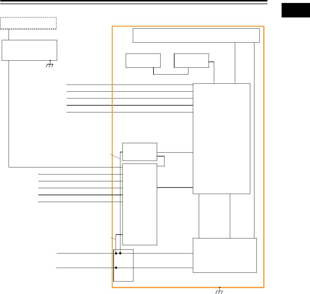
1-67 Section 1 Overview
1
2
3
4
5
6
7
8
9
10
11
12
13
14
15
16
17
18
19
20
21
22
23
24
25
26
27
付録
150/250V TTYCSLA-4
AIS
(IEC61162-2)
GYRO COMPASS
(IEC61162-2)
No.1 DGPS
(IEC61162-1)
SDME
(IEC61162-1)
BNWAS
(Dry Contact)
CML-836AC
W841:7ZCNA4164(1m)
CAT-5 LAN Cable
NQE-1143
Junction Box
(Option)
NCE-5605
Trackball Operation Unit
NBD-913
Power Supply Unit
NOTE: ELIMINATING THE INTERFERENCE ON FREQUENCIES USED FOR MARINE COMMUNICATIONS AND
NAVIGATION DUE TO OPERATION OF THE RADAR,
ALL CABLES OF THE RADAR ARE TO BE RUN AWAY FROM THE CABLES OF RADIO EQUIPMENT.
(ex. RADIOTELEPHONE, COMMUNICATIONS RECEIVER and DIRECTION FINDER. etc..)
ESPECIALLY INTER-WIRING CABLES BETWEEN SCANNER UNIT AND DISPLAY UNIT OF THE RADAR
SHOULD NOT BE RUN PARALLEL WITH THE CABLES OF RADIO EQUIPMENT.
150/250V TTYCSLA-1
150/250V TTYCSLA-1
150/250V TTYCSLA-1
150/250V TTYCSLA-1
NWZ-207
19inch Monitor Unit
(Option)
CML-901
W71:7ZCNA4147(0.65m)
CML-901
W61:7ZCNA4151(0.75m)
CML-901
W73:7ZCNA4149(1.05m)
NCE-5625
Keyboard Operation Unit
(Option)
W64:7ZCNA4187(0.40m)
CWA-245 19inch Display Unit Mount Kit
NQA-2443
Sensor LAN
Switch Unit
(Option)
150/250V TTYCSLA-4
AIS
(IEC61162-2)
GYRO COMPASS
(IEC61162-2)
No.1 DGPS
(IEC61162-1)
SDME
(IEC61162-1)
BNWAS
(Dry Contact)
150/250V TTYCSLA-1
150/250V TTYCSLA-1
150/250V TTYCSLA-1
150/250V TTYCSLA-1
CAT-5 LAN Cable
NDC-1590
Central Control Unit
CML-901
W53:7ZCNA4156A(0.55m)
CML-901
W51:7ZCNA4154(0.8m)
Inner wiring
24VDC/Max2A
(For Junction Box:SLC)
Inner wiring
24VDC/Max0.4A
(For LAN Unit)
CQD-2312
Relay
Terminal
Transitional Source of
Emergency Electric Power
24VDC/Max300W
(For System Backup)
0.6/1kV DPYCYS-16
0.6/1kV DPYCY-6
Ship's Main
AC220V 1PH/Max240VA
Inner wiring
24VDC
Inner wiring
AC220V 1PH
NQE-3141-4A/8A
Interswitch Unit
(Option)
Scanner Unit
(For Radar Overlay)
2695111153 Interswitch cable
General System Diagram of JAN-7201

Section 1 Overview 1-68