Japan Radio NKE2632 Solid State S-Band Marine Radar User Manual Installation Manual Part 1
Japan Radio Co Ltd. Solid State S-Band Marine Radar Installation Manual Part 1
Contents
- 1. Installation Manual Part 1
- 2. Installation Manual Part 2
- 3. Installation Manual Part 3
- 4. Installation Manual Part 4
- 5. Installation Manual Part 5
- 6. Installation Manual Part 6
- 7. Installation Manual Part 7
- 8. Installation Manual Part 8
- 9. Installation Manual Part 9
- 10. Installation Manual Part 10
- 11. Installation Manual Part 11
- 12. Instruction Manual Operation Part 1
- 13. Instruction Manual Operation Part 2
- 14. Instruction Manual Operation Part 3
- 15. Instruction Manual Operation Part 4
- 16. Instruction Manual Funtion Part 1
- 17. Instruction Manual Funtion Part 2
- 18. Instruction Manual Funtion Part 3
- 19. Instruction Manual Funtion Part 4
- 20. Instruction Manual Funtion Part 5
- 21. Instruction Manual Funtion Part 6
Installation Manual Part 1


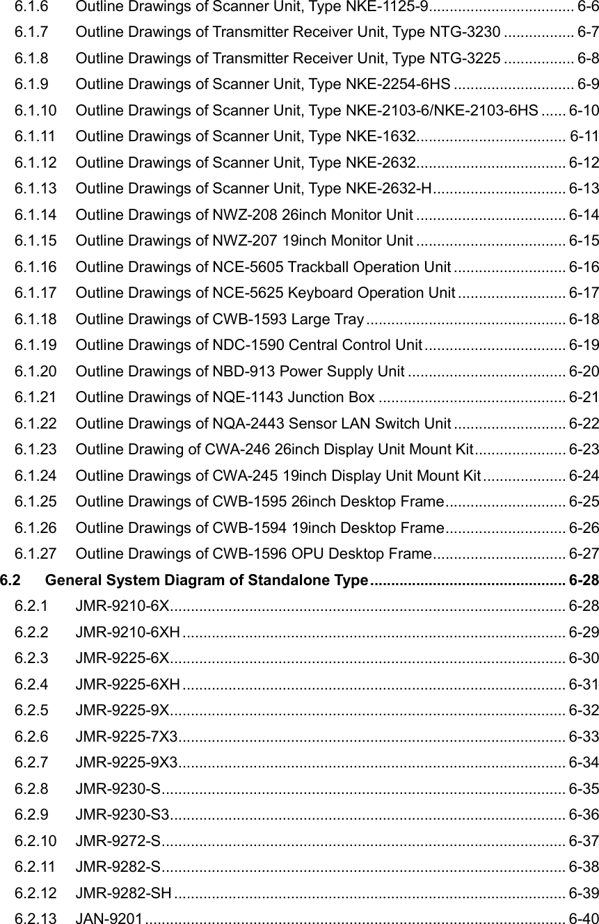
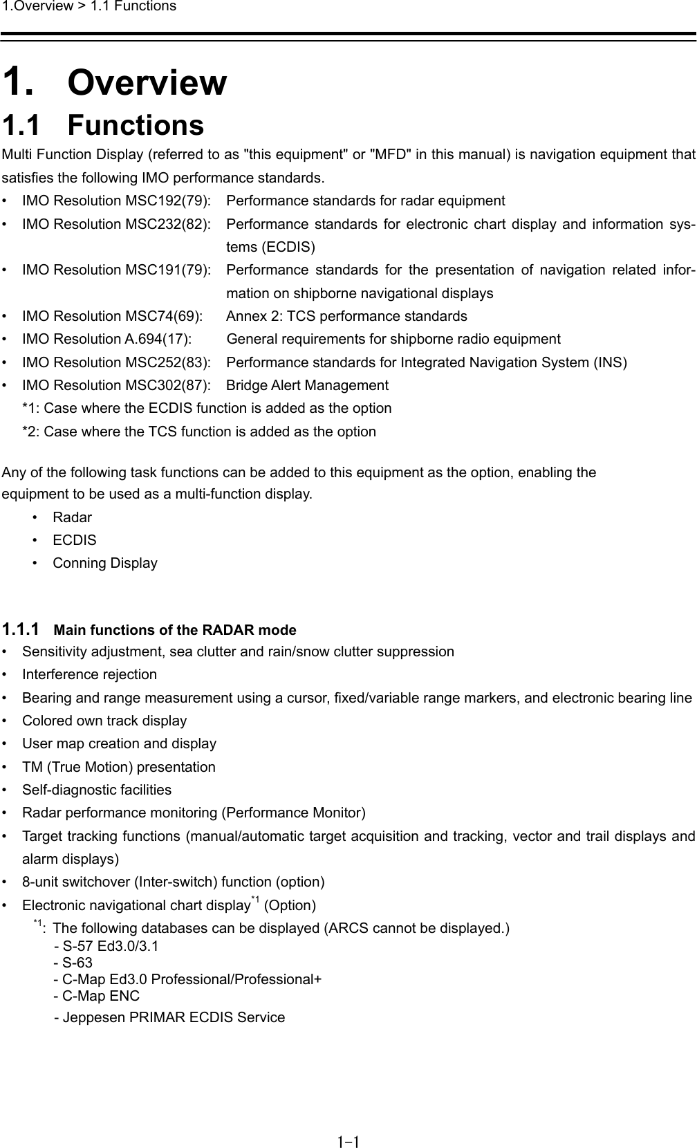
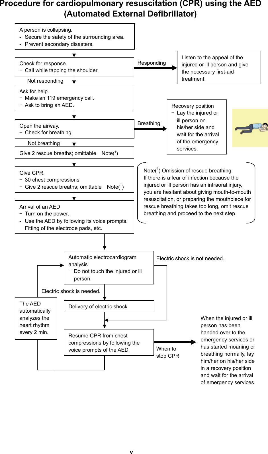
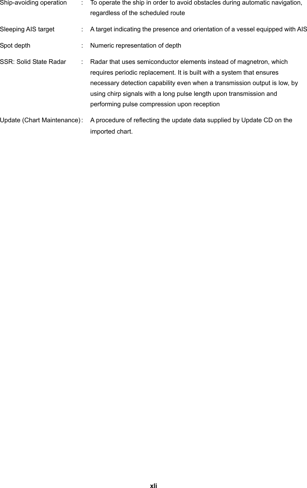
![iii Treatment to Give When the Patient Has a Pulse Beating but Has Ceased to Breathe Performing mouth-to-mouth artificial respiration - Fig. 1 (1) Bend the patient's face backward until it is directed to look back. (A pillow may be placed under the neck.) (2) Pull up the lower jaw to open up the airway. (To spread the airway) (3) Pinching the patient's nose, breathe deeply and blow your breath into the patient's mouth strongly, with care to close it completely. Then, move your mouth away and take a deep breath, and blow into his or her mouth. Repeat blowing at 10 to 15 times a minute (always with the patient's nostrils closed). (4) Continue artificial respiration until natural respiration is restored. (5) If the patient's mouth won't open easily, insert a pipe, such as one made of rubber or vinyl, into either nostril. Then, take a deep breath and blow into the nostril through the pipe, with the other nostril and the mouth completely closed. (6) The patient may stand up abruptly upon recovering consciousness. Keep the patient lying calmly, giving him or her coffee, tea or any other hot drink (but not alcoholic drink) to keep him or her warm. Mouth-to-mouth artificial respiration with the patient's head lifted [1] (1) Lift the back part of the patient's head. Support the forehead with one of your hand and the neck with the other hand.[1]. Many patients will have their airways opened by lifting their head in this way to ease mouth-to-mouth artificial respiration. [2] (2) Closing the patient's mouth with your mouth, press your cheek against the patient's nose [2]. Alternatively, hold the patient's nose with your finger to prevent air leak [3]. [3] (3) Blowing air into the patient's lungs. Blow air into the patient's lungs until chest is seen to rise. The first 10 breaths must be blown as fast as possible. Fig. 1 Mouth-to-mouth artificial respiration](https://usermanual.wiki/Japan-Radio/NKE2632.Installation-Manual-Part-1/User-Guide-2791034-Page-5.png)
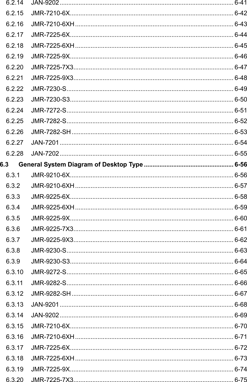
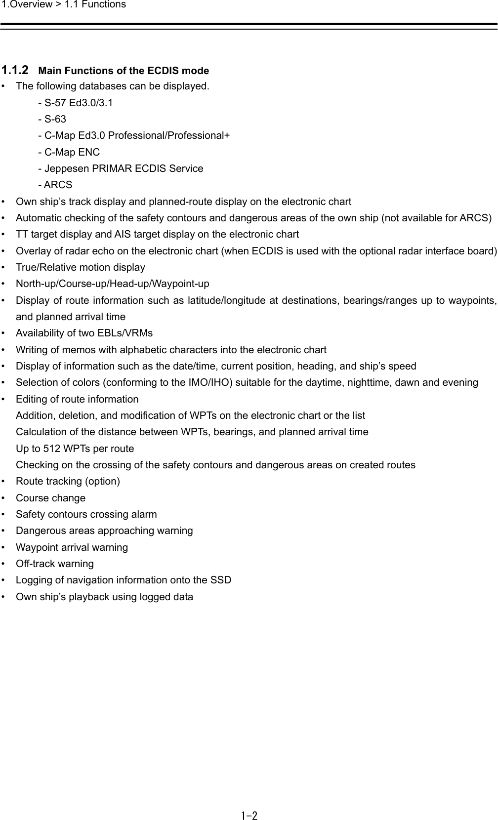
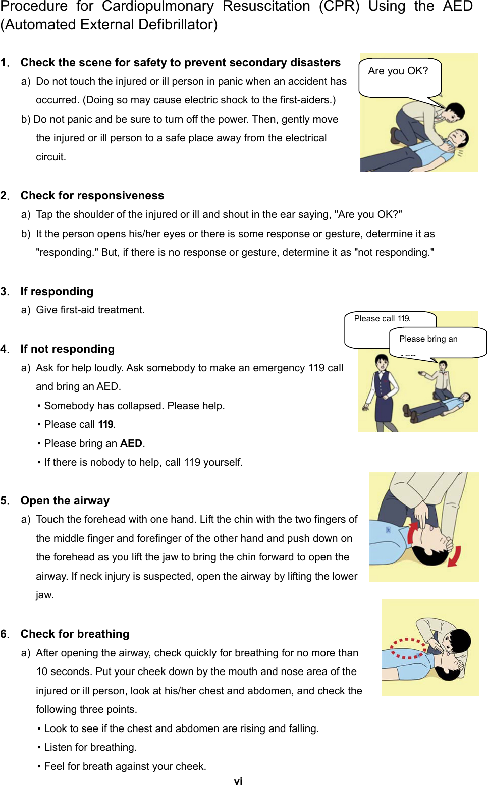
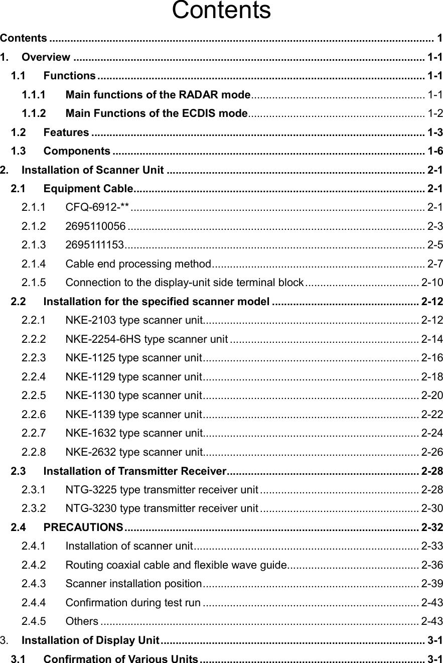
![iv Treatment to Give When the Patient Has No Pulse Beating and Has Ceased to Breathe Performing cardiac massage - Fig. 2 If the patient has no pulse beating, with the pupils open and no heartbeat being heard, the patient has a cardiac arrest and requires immediate artificial respiration. Continue this until a medical specialist arrives, and follow his or her directions after that. (1) Putting one hand on about the lower one third of the patient's ribs and the other hand over the back of the first, with your elbow fully stretched (with bended elbow, you can’t press to the extent the patient’s ribs are depressed), apply your body weight to the hands to press the patient's body until it is depressed about 2 cm (Repeat this about 50 times a minute). (Cardiac massage) (2) If only one first-aider is available, perform a cardiac massage about 15 times and then give mouth-to-mouth artificial respiration 2 times. Repeat this sequence. If two first-aiders are available, while one person performs a cardiac massage 15 times, the other should give mouth-to-mouth artificial respiration 2 times. Repeat this sequence. (Combined cardiac massage and mouth-to-mouth artificial respiration method) (3) Check the patient's pupils and feel the pulse from time to time. When the pupils are restored to normal and the pulse begins to beat regularly, stop treating and keep the patient calm while giving him or her coffee, tea or any other hot drink to keep him or her warm while watching him or her carefully. Fig. 2 Cardiac massage [1] [3] [2] [4]](https://usermanual.wiki/Japan-Radio/NKE2632.Installation-Manual-Part-1/User-Guide-2791034-Page-6.png)

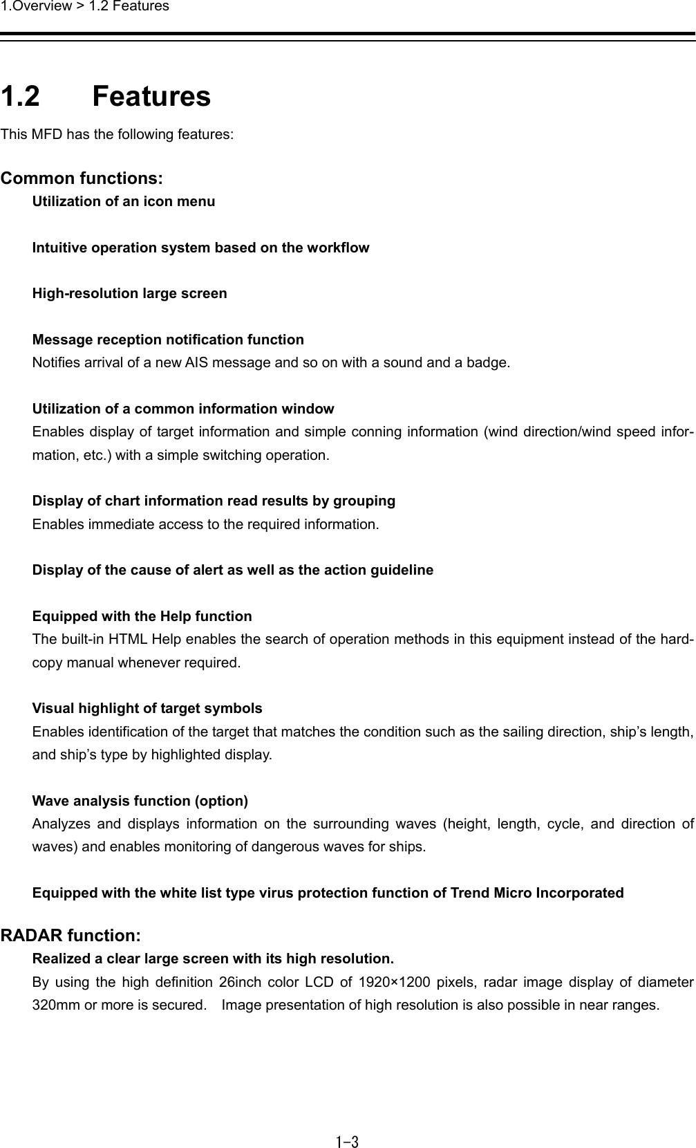
![xvi Do not use the offset function during navigation. If the equipment is used with the offset value entered as the own ship position (deviated from the actual position), accidents may result. When the offset values are entered, the [Offset] badge is displayed at the position display on the Own Ship Information. Check the indication, and cancel the offset function if necessary. Also, the message “Position Shift” is displayed in the message display area. If the LCD module breaks and the liquid inside spills out to stick to your skin, wash it off immediately under running water for more than 15 minutes. If you find any skin problem afterwards, consult a doctor immediately. If the liquid gets in your eye, wash it off immediately under running water for more than 15 minutes, and then, consult a doctor as soon as possible. Before starting automatic sailing, be sure to check the safety of the route and the safety when crossing safety contour. Otherwise, accidents may result. If the own ship has arrived at the boundary of a WPT during automatic sailing, be sure to check the safety and perform turning manually by the operator him/herself. Otherwise, the ship keeps the course with the leg bearing, and accidents may result. Input the ship’s parameter accurately according to the specification of the ship. Otherwise, accidents may result.](https://usermanual.wiki/Japan-Radio/NKE2632.Installation-Manual-Part-1/User-Guide-2791034-Page-18.png)
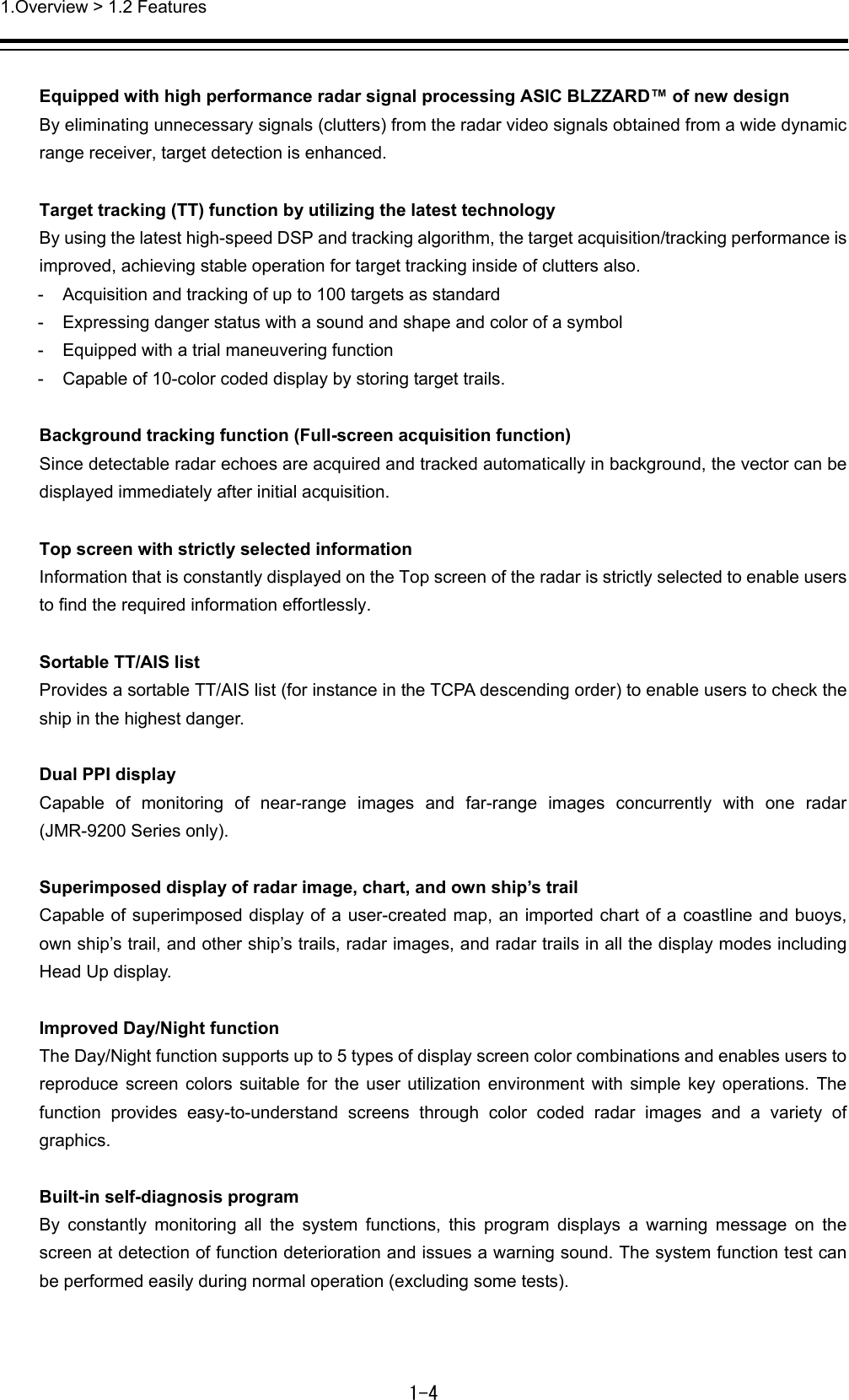
![xvii Use the radar only as a navigation aid. The final navigation decision must always be made by the operator him/herself. Making the final navigation decision based only on the radar display information may cause accidents such as collisions or running aground. A malfunction as the screen is disordered or unshown may occur if the power in the ship is instantaneously interrupted during operation of the radar. In this case, the power should be turned on again. Use Target Tracking (TT) function only as a navigation aid. The final navigation decision must always be made by the operator him/herself. Making the final navigation decision based only on tracking target information may cause accidents. Tracking target information such as vector, target numerical data, and alarms may contain some errors. Also, targets that are not detected by the radar cannot be acquired or tracked. Making the final navigation decision based only on the radar display may cause accidents such as collisions or running aground. When using the [AUTO SEA] function, never set the suppression level too high canceling out all image noises from the sea surface at close range. Detection of not only echoes from waves but also targets such as other ships or dangerous objects will become inhibited. When using the [AUTO SEA] function, make sure to choose the most appropriate image noise suppression level. When using the [AUTO RAIN] function, never set the suppression level too high. Detection of not only echoes from the rain or snow but also targets such as other ships or dangerous objects will become inhibited. When using the [AUTO RAIN] function, make sure to choose the most appropriate image noise suppression level. When setting a guard zone, make sure to properly adjust gain, sea-surface reflection suppression level, and rain/snow reflection suppression level so that the optimal target images are always on the radar screen. The guard zone alarm will not be activated for targets undetected by the radar, and it may result in accidents such as collisions. The simulation function is used exclusively for deciding whether or not target tracking is properly operating. Therefore, never use this function unless you wish to check target tracking operations. Note especially that, if this function is used during actual navigation, simulated targets are displayed and may become confused with other actual targets. Therefore, never use this function during actual navigation.](https://usermanual.wiki/Japan-Radio/NKE2632.Installation-Manual-Part-1/User-Guide-2791034-Page-19.png)
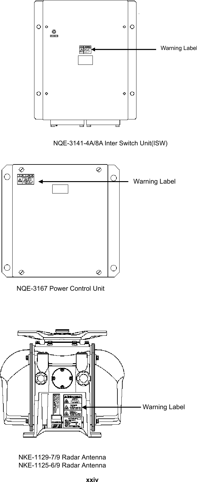
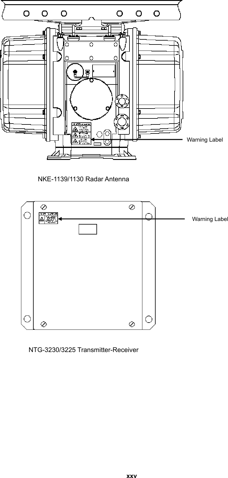
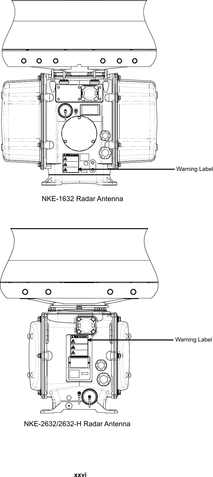
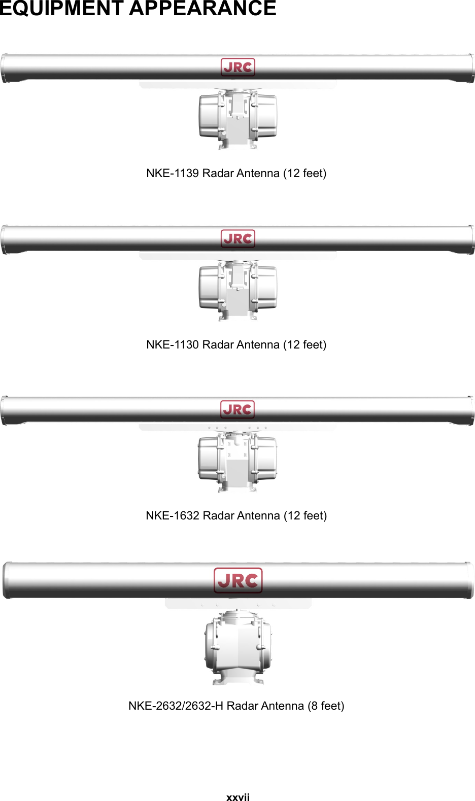

![3.6 Connections with Scanner and Transceiver .................................................. 3-99 3.6.1 NKE-1125, NKE-1129, NKE-1130, NKE-1139, NKE-1632, NKE-2632 SCANNERS ............................................................................................................. 3-100 3.6.2 NKE-2103, NKE-2254 SCANNERS .......................................................... 3-101 3.6.3 Settings for RADAR I/F Circuit .................................................................. 3-102 3.7 Connection with Sensors ............................................................................... 3-104 3.7.1 IEC61162-1 Connections ........................................................................... 3-105 3.7.2 IEC61162-2 Connections ........................................................................... 3-107 3.7.3 LAN Connection ......................................................................................... 3-110 3.7.4 Contact Input ............................................................................................. 3-114 3.7.5 Contact Output ........................................................................................... 3-115 3.7.6 Connections with Gyro Compasses and Electromagnetic Speed Logs ... 3-119 3.7.7 Settings for CMJ-554 GYRO I/F Circuit .................................................... 3-120 3.7.8 Connection with Analog Sensors ............................................................... 3-124 3.7.9 Backup of sensor signal ............................................................................ 3-127 3.8 Connection with ECDIS .................................................................................. 3-130 3.8.1 Radar Overlay ............................................................................................ 3-130 3.8.2 Target Tracking .......................................................................................... 3-131 3.9 Connection with RADAR ................................................................................ 3-132 3.9.1 Radar Overlay ............................................................................................ 3-132 3.9.2 Target Tracking .......................................................................................... 3-133 3.10 Connection with BNWAS ............................................................................... 3-134 3.11 Ground Connection ........................................................................................ 3-135 3.11.1 Shield for Equipment ................................................................................. 3-135 3.11.2 Cables for Equipment ................................................................................ 3-135 3.11.3 Mounting Location ..................................................................................... 3-135 3.11.4 Grounding .................................................................................................. 3-135 3.12 Installation of Power Cable ............................................................................ 3-136 3.12.1 Input Voltage Specification ........................................................................ 3-136 3.12.2 Connecting Power Cable ........................................................................... 3-137 3.13 Initialization for the specified model ............................................................ 3-138 3.14 Other Labels .................................................................................................... 3-147 3.14.1 Position of labels........................................................................................ 3-148 4. Initial Setting ............................................................................................................... 4-1 4.1 Service Menu [ALL] ............................................................................................. 4-2 4.2 Installation Information [ALL] ............................................................................ 4-7](https://usermanual.wiki/Japan-Radio/NKE2632.Installation-Manual-Part-1/User-Guide-2791034-Page-46.png)
![4.3 Setting Up a Language [ALL] ............................................................................. 4-9 4.4 Subsystem Installation [ALL] ........................................................................... 4-10 4.5 Setting Up CCRP (Consistent Common Reference Point) [ALL] ................. 4-15 4.6 Setting Up a Serial Port [ALL] .......................................................................... 4-17 4.7 Setting Contacts (Contact Input/Output) [ALL] ........................................... 4-28 4.8 CAM Configuration and Setting [ALL] ............................................................ 4-35 4.9 Setting A/D (Analog/Digital) [ALL] ................................................................... 4-45 4.10 Setting Data Output [RADAR][ECDIS] ................................................................... 4-51 4.11 Network Setting [ALL] ....................................................................................... 4-56 4.12 Redundancy Setting [ALL] ............................................................................... 4-62 4.13 Setting Ship’s Parameters [ALL] ........................................................................ 4-64 4.14 Setting Alert [ALL] ............................................................................................. 4-65 4.15 Operation Setting at AC Power Failure (Insufficient AC power supply) [ALL] 4-67 4.16 Setting Interswitch [RADAR] .............................................................................. 4-69 4.17 Setting VDR [RADAR][ECDIS] ................................................................................ 4-71 4.18 Setting Autosail (Automatic Sailing System) [ECDIS] .................................... 4-73 4.19 Setting AIS [RADAR][ECDIS] .................................................................................. 4-80 4.20 Setting Display Size [ALL] ................................................................................ 4-81 4.21 Tune Adjustment [RADAR] ................................................................................. 4-83 4.22 Bearing Adjustment [RADAR][ECDIS] ................................................................... 4-84 4.23 Range Adjustment [RADAR][ECDIS] ..................................................................... 4-85 4.24 Master/Slave Radar Operation Mode [RADAR][ECDIS] ....................................... 4-86 4.25 Setting an Antenna Height [RADAR][ECDIS] .......................................................... 4-87 4.26 Tune Peak Adjustment [RADAR] ....................................................................... 4-88 4.27 Setting a Tune Indicator (tuning indicator level) [RADAR] ............................. 4-89 4.28 Setting Output BP (Radar Antenna Bearing Pulse Output) [RADAR] ........... 4-90 4.29 Performance Monitor Adjustment [RADAR] ............................................................ 4-91 4.30 Setting Sector Blank (RADAR Screen Only) [RADAR] .................................... 4-99 4.31 Setting TNI Blank [RADAR] .............................................................................. 4-100 4.32 Setting Input BP Count [RADAR][ECDIS] ........................................................... 4-101 4.33 Setting Output BP Count [RADAR] ................................................................. 4-102 4.34 Echo Noise Level Adjustment [RADAR][ECDIS] ................................................ 4-103 4.35 TT (Target Tracking) Function Adjustment (RADAR Screen Only) [RADAR] .......... 4-104 4.36 Adjusting MBS [RADAR][ECDIS] ......................................................................... 4-110 4.37 Setting Cable Attenuation [ALL] ..................................................................... 4-111](https://usermanual.wiki/Japan-Radio/NKE2632.Installation-Manual-Part-1/User-Guide-2791034-Page-47.png)
![4.38 Verifying Storage [ALL] .................................................................................. 4-114 4.39 RADAR Adjustment (RADAR Screen Only) [RADAR] ................................... 4-115 4.40 Operating Time Setup [ALL] ........................................................................... 4-118 5. Option Unit .................................................................................................................. 5-1 5.1 Installation of Interswitch Unit .......................................................................... 5-1 5.1.1 End processing of Interswitch cable(2695111153) ........................................ 5-1 5.1.2 Connection of equipment cable ..................................................................... 5-2 5.1.3 NQE-3141-4A Inter-board connection diagram ............................................. 5-4 5.1.4 Installation of interswitch unit ........................................................................ 5-5 5.1.5 Settings of Interswitch ................................................................................... 5-7 5.1.6 Confirmation after installation ...................................................................... 5-12 5.2 Installation of Power Control Unit ................................................................... 5-13 5.2.1 Connection with NKE-2103 type and NKE-2254-6HS type scanner units .. 5-13 5.2.2 Connections to NKE-1125, NTG-3225, NKE-1130, NTG-3230, NKE-1632 and NKE-2632 ................................................................................................................... 5-15 5.2.3 End processing of 2695110056 cable ......................................................... 5-15 5.2.4 End processing of each cable core ............................................................. 5-15 5.2.5 Connection to display unit ........................................................................... 5-15 5.2.6 Outline Drawing of NQE-3167 Power Control Unit ..................................... 5-16 5.2.7 Inter –board connection diagram of power control unit ............................... 5-18 5.3 Connection of VDR ........................................................................................... 5-26 5.3.1 Connection with LAN (IEC61162-450) ........................................................ 5-26 5.3.2 Connection with Analog RGB ...................................................................... 5-26 5.4 Printer ................................................................................................................. 5-28 5.4.1 Printer Composition ..................................................................................... 5-28 5.4.2 Printer Assembly .......................................................................................... 5-29 5.4.3 Setting Printer .............................................................................................. 5-30 5.4.4 Equipment setup .......................................................................................... 5-38 5.4.5 Confirming Printing Operation ..................................................................... 5-40 6. Appendix ..................................................................................................................... 6-1 6.1 Outline Drawing .................................................................................................. 6-1 6.1.1 Outline Drawings of Scanner Unit, Type NKE-1139 ...................................... 6-1 6.1.2 Outline Drawings of Scanner Unit, Type NKE-1130 ...................................... 6-2 6.1.3 Outline Drawings of Scanner Unit, Type NKE-1129-7................................... 6-3 6.1.4 Outline Drawings of Scanner Unit, Type NKE-1129-9................................... 6-4 6.1.5 Outline Drawings of Scanner Unit, Type NKE-1125-6................................... 6-5](https://usermanual.wiki/Japan-Radio/NKE2632.Installation-Manual-Part-1/User-Guide-2791034-Page-48.png)