Japan Radio NKE2632 Solid State S-Band Marine Radar User Manual Instruction Manual Operation Part 2
Japan Radio Co Ltd. Solid State S-Band Marine Radar Instruction Manual Operation Part 2
Contents
- 1. Installation Manual Part 1
- 2. Installation Manual Part 2
- 3. Installation Manual Part 3
- 4. Installation Manual Part 4
- 5. Installation Manual Part 5
- 6. Installation Manual Part 6
- 7. Installation Manual Part 7
- 8. Installation Manual Part 8
- 9. Installation Manual Part 9
- 10. Installation Manual Part 10
- 11. Installation Manual Part 11
- 12. Instruction Manual Operation Part 1
- 13. Instruction Manual Operation Part 2
- 14. Instruction Manual Operation Part 3
- 15. Instruction Manual Operation Part 4
- 16. Instruction Manual Funtion Part 1
- 17. Instruction Manual Funtion Part 2
- 18. Instruction Manual Funtion Part 3
- 19. Instruction Manual Funtion Part 4
- 20. Instruction Manual Funtion Part 5
- 21. Instruction Manual Funtion Part 6
Instruction Manual Operation Part 2
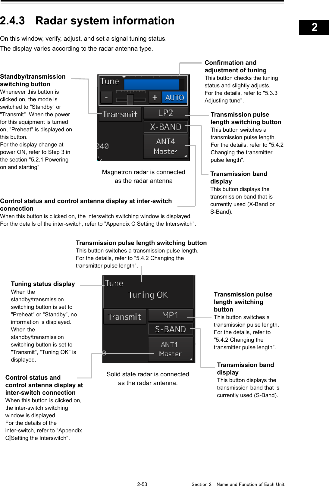
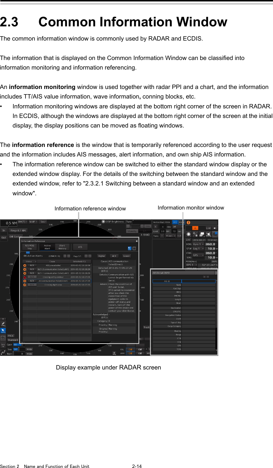
![2-1 Section 2 Name and Function of Each Unit 1 2 3 4 5 6 7 8 9 10 11 12 13 14 15 16 17 18 19 20 21 22 23 24 25 APP A APP B 1 Section 2 Name and Function of Each Unit 2.1 Name and Main Function of the Operation Unit 2.1.1 Trackball operation unit When turning off the power supply, do not hold down the power button of the operation unit. Otherwise, a trouble may occur due to termination failure. No. Name Function outline 1 Power supply button Use this button to turn on and off this equipment. 2 [MULTI] dial • Turn this dial to operate the function that is assigned to the [MULTI] dial such as the Display Brightness function. • If the [MULTI] dial is held down, the Display Brightness function is assigned to the [MULTI] dial forcibly. 3 USB terminal Connects a USB flash memory. 4 [SILENCE] key Stops the alert buzzer. 5 [ALERT ACK] key Acknowledging the alert. 6 [ZOOM IN] key • "Observation range" Setting will increment one step smaller in the case of RADAR. • "Scale" Setting will increment one step larger in the case of ECDIS. • When this key is held pressed, setting will step continuously until released. [1] [2] [3] [6] [7] [4] [5] [8] [9] [10]](https://usermanual.wiki/Japan-Radio/NKE2632.Instruction-Manual-Operation-Part-2/User-Guide-2791057-Page-1.png)
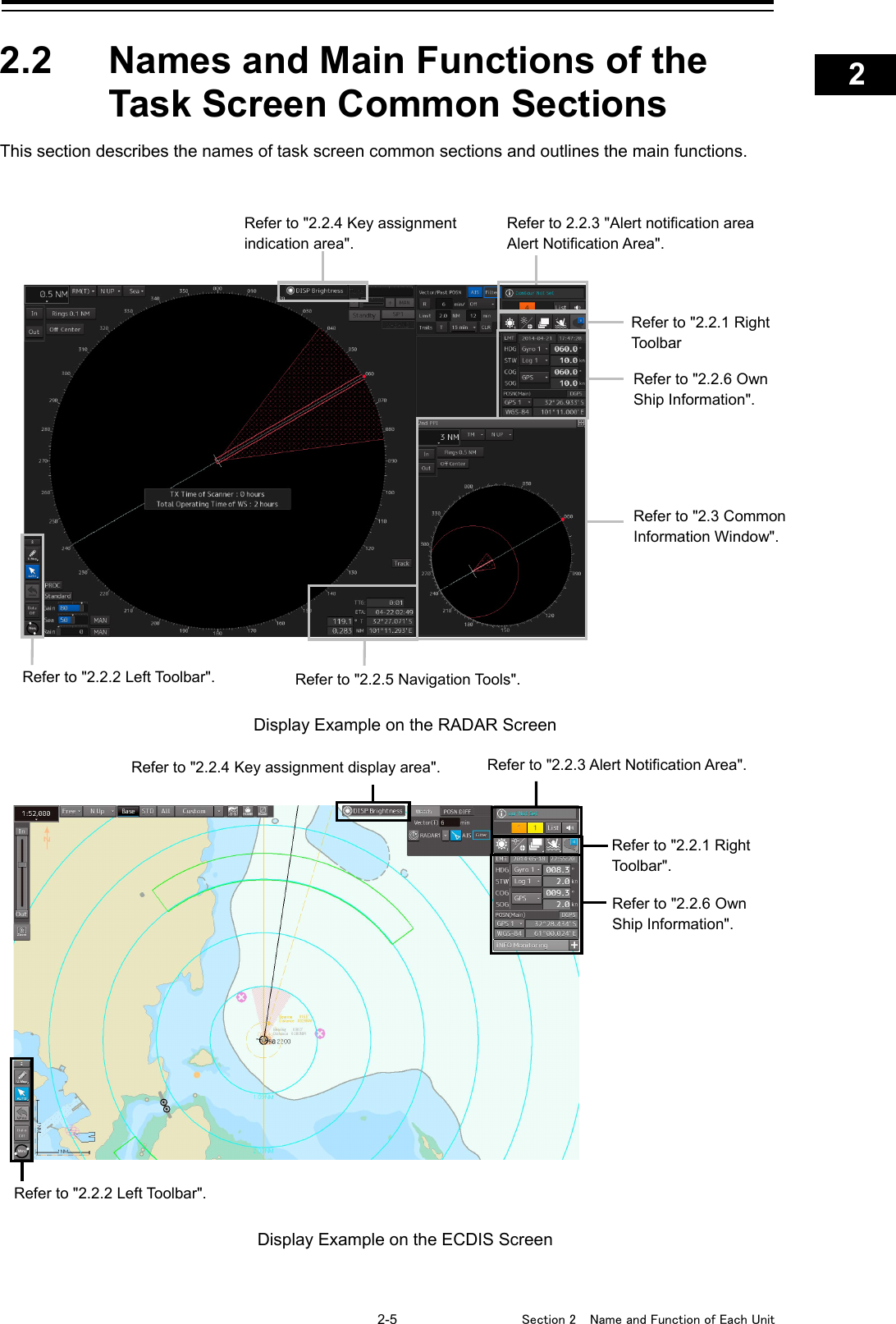
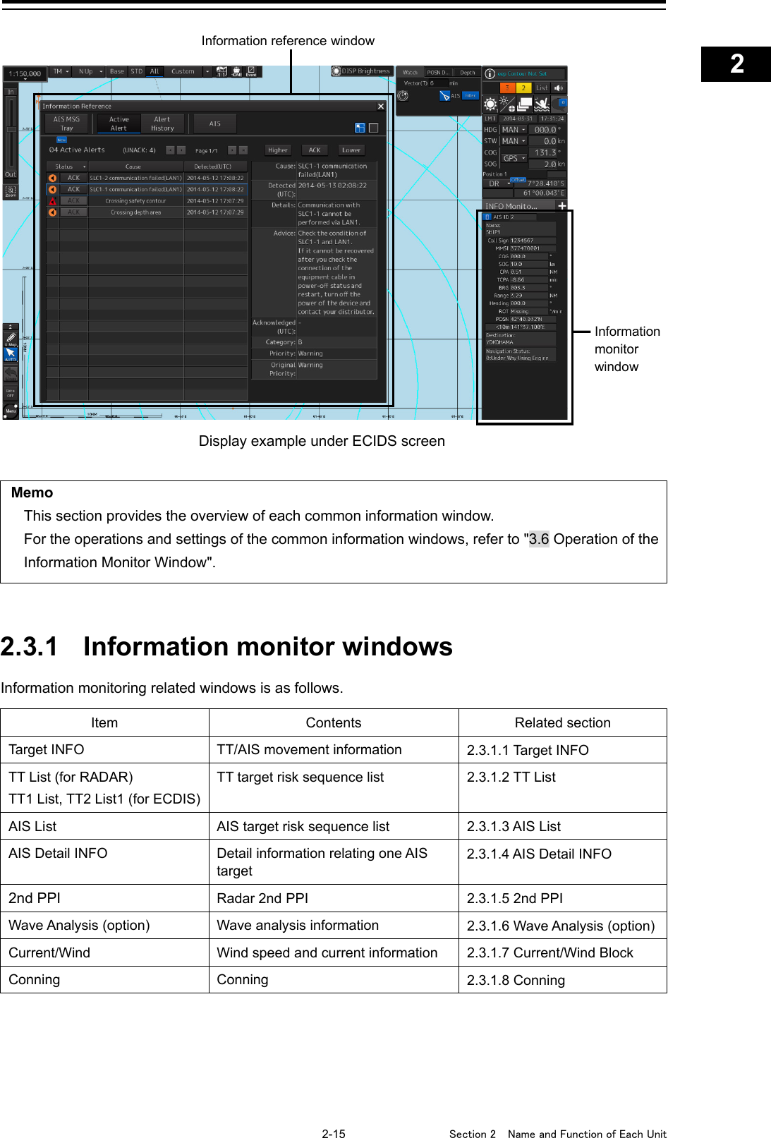
![Section 2 Name and Function of Each Unit 2-2 No. Name Function outline 7 [ZOOM OUT] key • "Observation range" Setting will increment one step larger in the case of RADAR. • "Scale" Setting will increment one step smaller in the case of ECDIS. • When this key is held pressed, setting will step continuously until released. 8 Track ball Moves the cursor on the screen. Use the track ball to specify a position or to perform various settings. 9 Left button • Use this button to select a function or determine the operation that is set. • The clicking of the left button once is referred to as "click" in this manual. • The clicking of the left button twice consecutively is referred to as "double click" in this manual. 10 Right button • Use this button to select a function or perform setting operation. • The clicking of the right button is referred to as "right click" in this manual. 2.1.2 Keyboard operation unit (Option) No. Name Function outline 1 [EBL] dial When this dial is turned, control moves in the EBL (PI) direction with control right. This dial also moves the cursor horizontally (in cursor move mode). 2 [VRM] dial When this dial is turned, control moves in the VRM (PI) direction with control right. This dial also moves the cursor vertically (in cursor move mode). 3 [RAIN] dial • When this dial is turned, the level of rain/snow clutters on the radar image is adjusted. • When this dial is pressed, the function mode is switched to manual/automatic. 4 [SEA] dial • When this dial is turned, the level of sea clutters on the radar image is adjusted. • When this dial is pressed, the function mode is switched to manual/automatic. 5 [GAIN] dial • When this dial is turned, the gain of the radar image is adjusted. • When this dial is pressed, the transmission pulse width is switched. 6 [TX STBY] key [For RADAR] • When this dial is pressed, the radar transmission status is switched to Standby or Transmit. [For ECDIS] When this dial is pressed, the radar image on the chart is switched to "On" or "Off". 7 [AZ] key • This key switches AZ to On/Off. • When this key is held down, the “[AZ] Key Assignment” dialog box appears. [1] [3] [15] [10] [2] [4] [5] [6] [9] [8] [14] [13] [12] [7] [11] [16]](https://usermanual.wiki/Japan-Radio/NKE2632.Instruction-Manual-Operation-Part-2/User-Guide-2791057-Page-2.png)
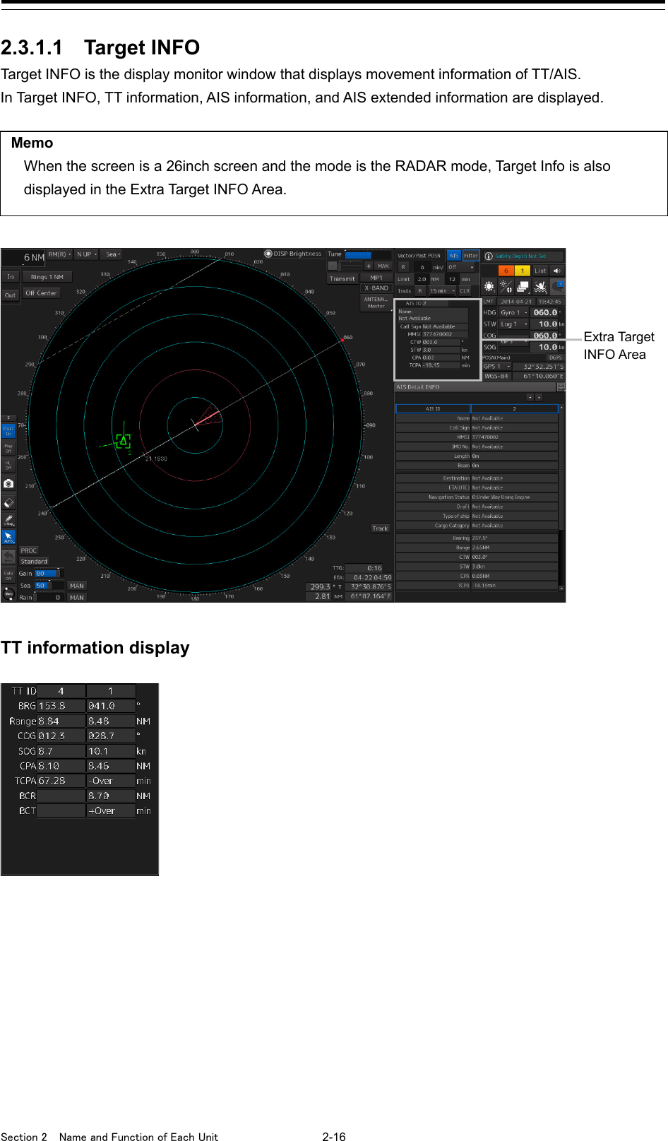
![2-3 Section 2 Name and Function of Each Unit 1 2 3 4 5 6 7 8 9 10 11 12 13 14 15 16 17 18 19 20 21 22 23 24 25 APP A APP B 1 No. Name Function outline 8 [HOME] key • Returns own ship to the home position within the display screen. - TM: Moves the own ship to the TM RESET position. - RM: Moves the own ship to the on-center position (when it is at off-center only). 9 [DAY NIGHT] key Switches the display color on the screen over 5 levels according to the brightness on the bridge. 10 [DISP OFF] key The assigned function is executed while the key is pressed. The function that can be assigned is Data Off or HL Off for RADAR and Data Off for ECDIS. 11 [PI] key • Switches the PI operation/display to On/Off. For PI operation, refer to "4.6 Using Parallel Index Lines (PI)". • When this key is held down, the cursor mode is changed to the floating PI mode. 12 [MOB] key • Displays the MOB symbol and the setting dialog box in the own ship’s position latitude/longitude. • When this key is held down, the MOB symbol and the setting dialog box are cleared. 13 [PANEL] key Whenever this key is pressed, the brightness of the panel on the operation unit is switched. 14 [USER1] key • Executes the function that is assigned to the key. • When this key is held down, the setting dialog box of the function that is assigned to the [USER1] key appears. 15 [USER2] key • Executes the function that is assigned to the key. • When this key is held down, the setting dialog box of the function that is assigned to the [USER2] key appears. 16 Keyboard The keyboard is used for input of numeric values and characters at operation of this equipment.](https://usermanual.wiki/Japan-Radio/NKE2632.Instruction-Manual-Operation-Part-2/User-Guide-2791057-Page-3.png)
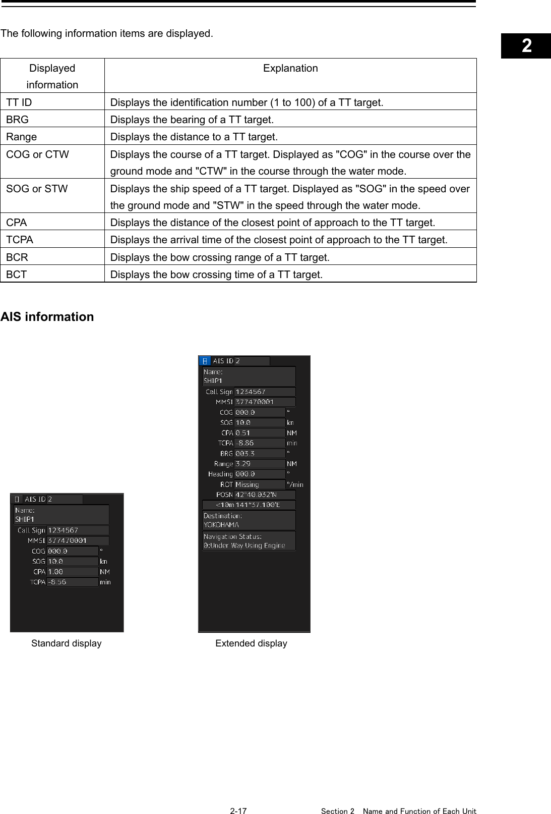
![Section 2 Name and Function of Each Unit 2-4 2.1.3 Display unit [Power] button When the Power button is pressed while the power of the display unit is turned off, the power is turned on. To turn off the power of the display unit, press the Power button for 5 seconds or longer. [Brightness Adjustment] buttons These buttons are used to adjust the brightness of the screen. The screen increases brightness by pressing the button. The screen decreases brightness by pressing the button. Memo Adjust the brightness of the screen to the extent it is not dazzling, taking into account the brightness of the surroundings and to the brightness which you can be easily observed the RADAR, the ECDIS screens. [Brightness Adjustment] [Power] button buttons](https://usermanual.wiki/Japan-Radio/NKE2632.Instruction-Manual-Operation-Part-2/User-Guide-2791057-Page-4.png)
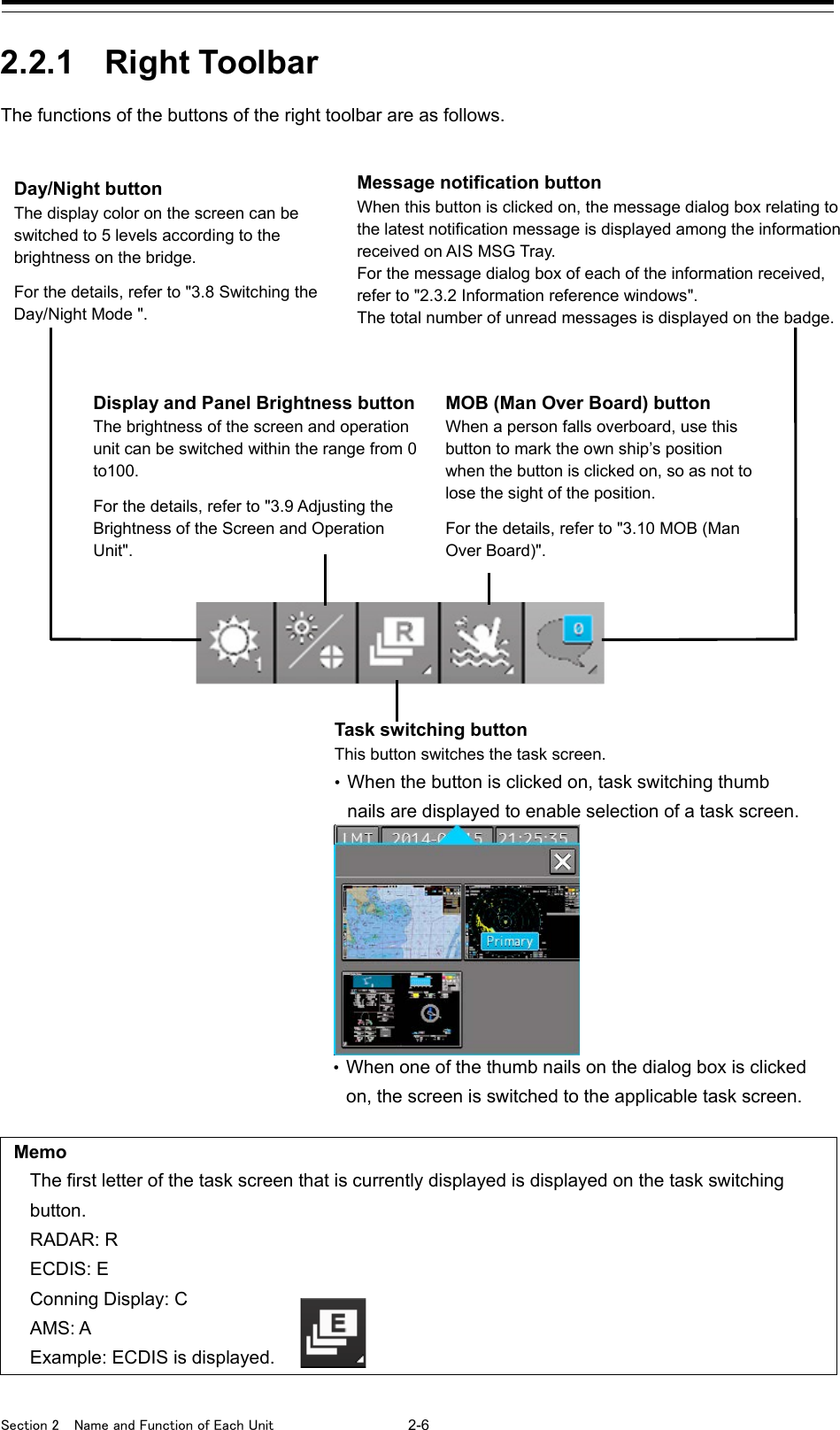
![Section 2 Name and Function of Each Unit 2-8 2.2.2.1 Buttons that are normally displayed [Auto] (Cursor mode selection) button When this button is clicked on, the cursor mode is switched to the AUTO mode. For the details of the cursor mode, refer to "3.12 Cursor AUTO Mode". PEN (Write tool) button Clicking on this button during user map creation, manual chart update or route planning brings up the corresponding operation mode. The mode name will be indicated on the button. Example: [U.Map] (User Map) mode [U. Map] (User Map) mode Clicking on the button when it indicates [U. Map] displays the drawing toolbar for user maps. *When this mode is used, the azimuth mode will be fixed to N UP (North UP). [Update] (Manual Update) mode Clicking on the button when it indicates [Update] displays the "Select Chart" dialog box if a chart to be manually updated has not been selected. If a chart to be manually updated is selected, the drawing toolbar for manual update will be displayed. *When this mode is used, the azimuth mode will be fixed to N UP (North UP). [Route] (Route Planning) mode Clicking on the button when it indicates [Route] brings up a new route planning mode if no route planning tab is open. If one or more route planning tabs are open, the system switches from the end of the routes currently being created to the WPT addition mode. [Undo] button Clicking on this button cancels the previous operation performed. -In user map creation mode -In manual update creation mode [Data OFF] button When this button is clicked on, only the main information is displayed from the screen display and other information is hidden. The following information items are displayed: RADAR - Echo/trail - Cursor ECDIS - Own ship’s symbol - Route - Temporary Route - Chart - Manual update object - EBL - VRM - Cursor *The chart is displayed when the display category is [Base]. [Menu] button When this button is clicked on, the top menu for the RADAR and ECDIS screens is displayed. For the details of the menu, refer to "3.4 Basic Menu Operations". Memo This equipment is operating normally when the [Menu] button is moving in animation mode. When this equipment is set to a freeze state, the Menu button stops and does not move. In this case, turn off the power once and turn it on again.](https://usermanual.wiki/Japan-Radio/NKE2632.Instruction-Manual-Operation-Part-2/User-Guide-2791057-Page-8.png)
![2-9 Section 2 Name and Function of Each Unit 1 2 3 4 5 6 7 8 9 10 11 12 13 14 15 16 17 18 19 20 21 22 23 24 25 APP A APP B 1 2.2.2.2 Buttons that are normally hidden 2.2.3 Alert notification area When an alert occurs, the alert status, the contents of the alert and the occurrence count are displayed in the alert notification area. For the details, refer to "3.7 Confirming and Acknowledging an Alert ". [Printer] button To print the screen, click on this button. (This button is displayed only when a printer is installed.) [Screen Capture] button When this button is clicked on, the screen that is currently displayed is captured. For the details, refer to "3.13 Saving the Screen that is Currently Displayed". [Map On/Off] button Clicking on this button switches to show or hide the user map. Even if the mode is set to Hide, the Mariner’s Mark/Line symbol and various Warning symbols are displayed. [Chart On/Off] button Clicking on this button switches to show or hide the chart. [HL Off] button When this button is clicked on, the Heading Line becomes hidden. For the details of the Heading Line, refer to "16.2.1 Setting up the Display of Own Ship Symbol". [Eraser tool] button When this button is clicked on, the User Map Erase mode is set, enabling continuous erasing.](https://usermanual.wiki/Japan-Radio/NKE2632.Instruction-Manual-Operation-Part-2/User-Guide-2791057-Page-9.png)
![Section 2 Name and Function of Each Unit 2-10 2.2.4 Key assignment indication area When the [MULTI] dial is turned, the assigned functions are operated. For the function assignment, refer to "3.14 [Multi] dial". 2.2.5 Navigation tools The tools that are used for measurement are displayed. [PI] button Use this button to operate the parallel index line cursor. For the details, refer to "4.6 Using Parallel Index Lines (PI)". [Cursor] (Cursor information display) button When this button is clicked on, the "Cursor Readout" dialog box appears. For the details, refer to "4.3 Using the Cross-hair Cursor". EBL/VRM operation button area Use this button to operate EBL/VRM. For the details, refer to "4.5.1 Measuring a range and a bearing with EBL and VRM"](https://usermanual.wiki/Japan-Radio/NKE2632.Instruction-Manual-Operation-Part-2/User-Guide-2791057-Page-10.png)
![2-11 Section 2 Name and Function of Each Unit 1 2 3 4 5 6 7 8 9 10 11 12 13 14 15 16 17 18 19 20 21 22 23 24 25 APP A APP B 1 2.2.6 Own Ship Information Do not use the offset function during navigation. If the equipment is used with the offset value entered as the own ship position (deviated from the actual position), accidents may result. When the offset values are entered, the [Offset] badge is displayed at the position display on the Own Ship Information. Check the indication, and cancel the offset function if necessary. Also, the message "Position Shift" is displayed in the message display area. This window displays the own ship’s information. • When using 1-axis log, heading speed component can be detected, but transverse speed component cannot be detected. Then leeway effect (component drifted by wind) cannot be detected. • When using 2-axes log, its accuracy in shallow waters may be deteriorated, and its speed in deep sea areas may be unable to be detected. • When using a GPS, COG accuracy is less than ±3° at speed: from 1kn to 17kn, and is less than ±1° at speed: more than 17kn. Sensor information Various sensor information items are displayed. [Sensor types] Sensor name Contents HDG Displays the value indicated by the ship’s heading sensor. STW Displays the value indicated by the speed through water sensor. COG/SOG Displays the value indicated by the speed over the ground sensor. [Sensor value background colors] Each background color represents the following meaning. Normal color: Normal sensor value Yellow: The reliability of the sensor value is deteriorating. Red: The sensor value is abnormal. UTC/Local date and time This button displays the current date and time. •When the button is clicked on, the time can be switched to the UTC time display or Local time display. •Set the time format by selecting [Maintenance] - [Date/Time/Time Zone]-[Display Style] on the menu. For the details, refer to "21.1.2 Setting Date/Time/Time Zone". See the next page.](https://usermanual.wiki/Japan-Radio/NKE2632.Instruction-Manual-Operation-Part-2/User-Guide-2791057-Page-11.png)
![Section 2 Name and Function of Each Unit 2-12 [Switching the sensor source] Select the sensor source in the [Source] combo box. The following sensor sources can be selected. When [Menu] is selected, the "Sensor Selection/Status" dialog is displayed. Sensor name Sensor source HDG MAN (Manual) *4, Gyro, Gyro 1*1*5, Gyro 2*1*5, MAG (MAG Compass)*5, G/C (GPS Compass) STW MAN (Manual) *4, Log, Log 1*2, Log 2*2 COG Log, Log 1*2, Log 2*2, GPSx*3 SOG *1: Only when there are two Gyros. *2: Only when there are two Logs. *3: When two or more GPS units are present, “x” indicates the unit number. *4: This can only be selected from the “Sensor Selection/Status” dialog. *5: When the Gyro Compass system that is used has the automatic switching function, the display of the sensor source changes automatically according to the switching condition. [1] The data name of the Position is displayed. [2] The sensor source of the Position is displayed. Select a sensor source in the [Source] combo box. Any of the following sensor sources can be selected. When [Menu] is selected, the “Sensor Selection/Status” dialog is displayed. Data name Sensor source POSN(Main) for ECDIS and Position for RADAR GPSx*, DR *: When two or more GPS units are present, “x” indicates the unit number. [1] [2] [3] [4] [5] See the previous page. Position Displays Position information.](https://usermanual.wiki/Japan-Radio/NKE2632.Instruction-Manual-Operation-Part-2/User-Guide-2791057-Page-12.png)
![2-13 Section 2 Name and Function of Each Unit 1 2 3 4 5 6 7 8 9 10 11 12 13 14 15 16 17 18 19 20 21 22 23 24 25 APP A APP B 1 [3] A geodetic positioning system is displayed. It is fixed to "WGS-84". [4] Positioning precision display When the positioning precision is differential positioning, "DGPS" is displayed. No information is displayed in the case of GPS single positioning. [5] Position (CCRP) The CCRP position indicated by the primary positioning sensor is displayed. Own ship’s position offset display When offset is set for the own ship’s position, the icon that indicates the offset status is displayed for the Position.](https://usermanual.wiki/Japan-Radio/NKE2632.Instruction-Manual-Operation-Part-2/User-Guide-2791057-Page-13.png)
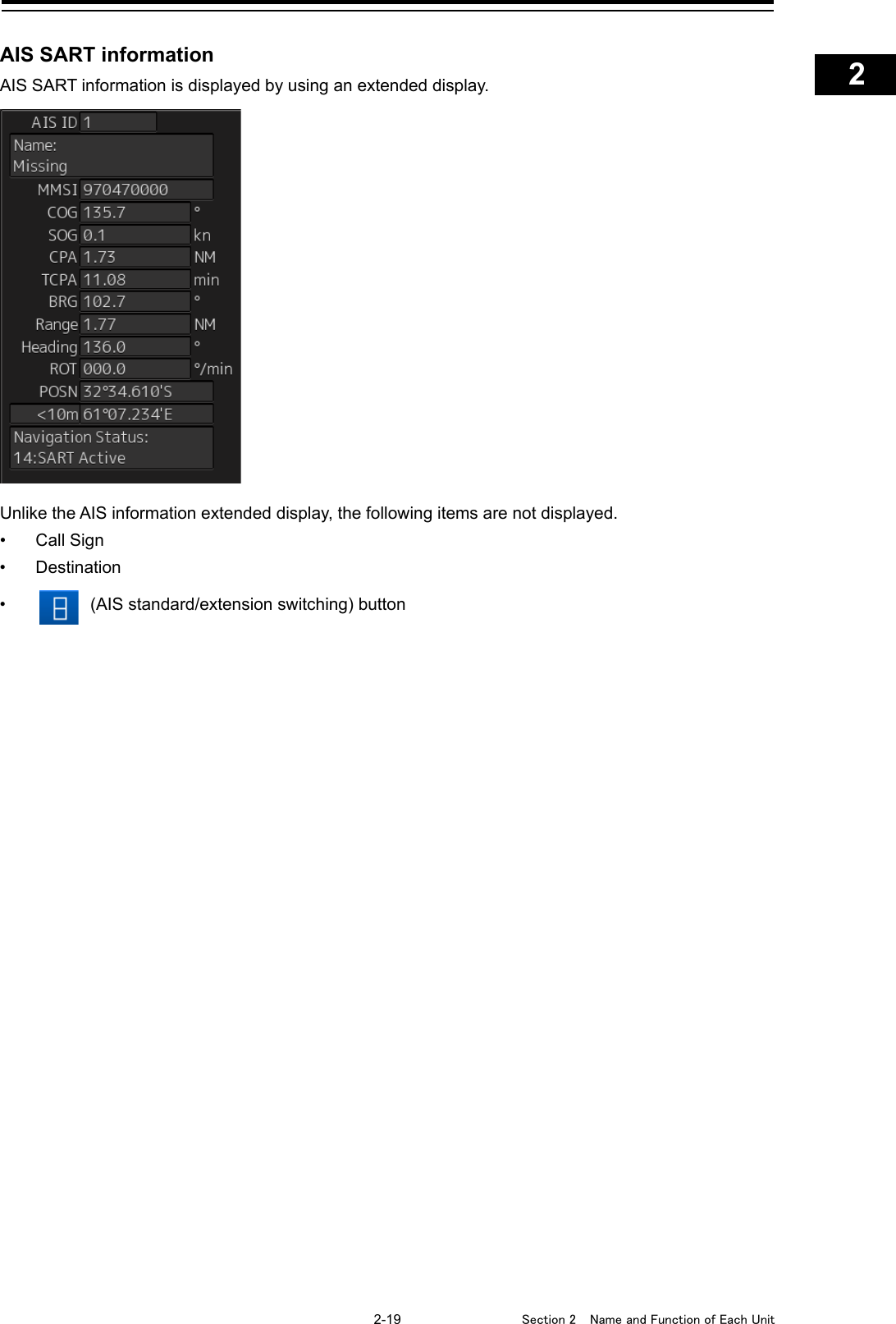
![Section 2 Name and Function of Each Unit 2-18 • AIS information of the target is displayed. • When the (AIS standard/extension switching) button is clicked on, the display is switched between the standard display and the extended display. • The following information items are displayed. Displayed information Explanation AIS ID Displays the identification number (1 to 1000) of an AIS target. *The maximum display number is 1000 as the option. Name Displays the ship name of an AIS target. Call Sign Displays a call sign. MMSI Displays a nine-digit identification number for a ship/ground station equipped with a DSC communication device. COG or Course Displays the course of an AIS target. Displayed as "COG" in the course over the ground mode and "Course" in the course through the water mode. SOG or STW Displays the ship speed of an AIS target. Displayed as "SOG" in the speed over the ground mode and "STW" in the speed through the water mode. CPA Displays the closest approach distance to an AIS target. TCPA Displays the time to reach the closest approach point to an AIS target. BRG* Displays the bearing of an AIS target. Range* Displays the distance to an AIS target. Heading* Displays the heading of an AIS target. ROT* Displays the turning speed of an AIS target. POSN and Position Accuracy* Displays the position of an AIS target and position-fix accuracy. When the position-fix accuracy is low, [>10m] is displayed. When the position-fix accuracy is high, [<10m] is displayed. Destination* Displays the destination of an AIS target. Navigation Status* Displays the navigation conditions of an AIS target. For detailed explanation, refer to "Navigation Status" in the table provided in "2.3.1.4 AIS Detail INFO". *: Extended display only](https://usermanual.wiki/Japan-Radio/NKE2632.Instruction-Manual-Operation-Part-2/User-Guide-2791057-Page-18.png)
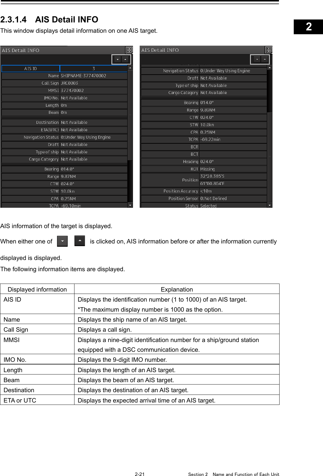
![2-23 Section 2 Name and Function of Each Unit 1 2 3 4 5 6 7 8 9 10 11 12 13 14 15 16 17 18 19 20 21 22 23 24 25 APP A APP B 1 Displayed information Explanation Cargo Category When the setting of the type of a ship is 2X, 4X, 6X, 7X, 8X or 9X, the digit shown at the end of the code represents the cargo/condition. X1 Category X(DG/HP/MP) X2 Category Y(DG/HP/MP) X3 Category Z(DG/HP/MP) X4 Category OS(DG/HP/MP) X9 No Additional Information X0 All Ships of This Type Bearing Displays the bearing of an AIS target. Range Displays the distance to an AIS target. COG or CSE Displays the course of an AIS target. Displayed as "COG" in the course over the ground mode and "CSE" in the course through the water mode. SOG or STW Displays the ship speed of an AIS target. Displayed as "SOG" in the speed over the ground mode and "STW" in the speed through the water mode. CPA Displays the closest approach distance to an AIS target. TCPA Displays the time to reach the closest approach point to an AIS target. BCR Displays the bow crossing range of an AIS target. BCT Displays the bow crossing time of an AIS target. Heading Displays the heading of an AIS target. ROT Displays the turning speed of an AIS target. Position Displays the position of an AIS target and position-fix accuracy. When the position-fix accuracy is low, [>10m] is displayed. When the position-fix accuracy is high, [<10m] is displayed. Position Sensor Displays the type of the position sensor used by an AIS target. 0: Not Defined 1: GPS 2: GLONASS 3: Combined GPS/GLONASS 4: Loran-C 5: Chayka 6: Integrated Navigation System 7: Surveyed 8: Galileo 15: Internal GNSS Status Status of an AIS target • Sleeping • Activated • Lost • Danger • Selected](https://usermanual.wiki/Japan-Radio/NKE2632.Instruction-Manual-Operation-Part-2/User-Guide-2791057-Page-23.png)
![Section 2 Name and Function of Each Unit 2-24 2.3.1.5 2nd PPI The setting items are the same as those of the main PPI setting except for the setting items that can be specifically set under 2nd PPI. For the details, refer to "2.4.1 Presentation and mode information". Note In “screen fixed display” (C mode), EBL/VRM is not displayed in the 2nd PPI. Memo When the numbers of the direction graduations become overlapped and cannot be distinguished, the numbers will be thinned out and displayed. [1] Range scale combo box Select a range scale from the combo box and set up the range scale. [2] [In] (Zoom In) button When this button is clicked on, the display is zoomed in by one level from the range scale. When the button is held down, the display is zoomed in continuously. RADAR Source ANT2 ▼[1] [2] [3] [5] [6] [7] [4]](https://usermanual.wiki/Japan-Radio/NKE2632.Instruction-Manual-Operation-Part-2/User-Guide-2791057-Page-24.png)
![2-25 Section 2 Name and Function of Each Unit 1 2 3 4 5 6 7 8 9 10 11 12 13 14 15 16 17 18 19 20 21 22 23 24 25 APP A APP B 1 [3] [Out] (Zoom Out) button When this button is clicked on, the display is zoomed out by one level from the range scale. When the button is held down, the display is zoomed out continuously. [4] Motion mode combo box Select a motion mode from the combo box and set up the motion mode. The mode operates by linking with the setting of the main PPI. [5] Bearing mode combo box Select a bearing mode from the combo box and set up the bearing mode The mode operates by linking with the setting of the main PPI. [6] Range rings display button When this button is clicked on, the range rings display surrounding the own ship is set to On/Off. [7] [Off Center] button When this button is clicked on, the off-center of the own ship’s position (CCRP) is set to On/Off.](https://usermanual.wiki/Japan-Radio/NKE2632.Instruction-Manual-Operation-Part-2/User-Guide-2791057-Page-25.png)
![Section 2 Name and Function of Each Unit 2-26 2.3.1.6 Wave Analysis (option) Wave Analysis analyzes sea clutters that are detected by a radar and measures the wave height, wave direction, cycle and wave length around own ship. 19inch screen [1] [4] [2] [6] [3] [5] [7] [8] [9]](https://usermanual.wiki/Japan-Radio/NKE2632.Instruction-Manual-Operation-Part-2/User-Guide-2791057-Page-26.png)
![2-27 Section 2 Name and Function of Each Unit 1 2 3 4 5 6 7 8 9 10 11 12 13 14 15 16 17 18 19 20 21 22 23 24 25 APP A APP B 1 26inch screen [1] [Mode] (Calculation execution mode) The calculation execution mode is displayed. Three modes are available, [Real Time], [Interval] and [Display]. • [Real Time] mode: Outputs analysis results at a 1-minute interval. • [Interval] mode: Outputs analysis results at the set interval (5 to 120 minutes). • [Display] mode: Displays the latest analysis result. Analysis is not performed. [2] [Rec RADAR] (Recording radar data log) Displays whether the recording of radar data log is set to ON or OFF. Radar echo data that is received from a sensor at the cycle of 2.4 seconds is saved in the png format (about 100KB/sheet) and inf file (about 1KB/sheet) as the log. The storing period can be set within the range from 1 to 300 days. [6] [1] [2] [4] [5] [8] [9] [7] [3]](https://usermanual.wiki/Japan-Radio/NKE2632.Instruction-Manual-Operation-Part-2/User-Guide-2791057-Page-27.png)
![Section 2 Name and Function of Each Unit 2-28 [3] [Last Update] (Analysis time) Displays the time when the last analysis was performed. Memo The time is displayed in the format that was set in [Display Style] after selecting [Maintenance] - [Date/Time/Time Zone] on the menu. [4] [DISP Mode] button Select a display mode of the wave direction. When displaying in North Up, set [N UP] by clicking on the button. When displaying in Head Up, set [H UP] by clicking on the button. [5] Analysis result Displays the analysis result. [Height] (wave height), [Length] (wave length), [Period] (wave cycle), and [Direction] (wave direction) are displayed for each Primary (primary waves) and Secondary (secondary waves) that come from multiple directions. [6] Status On the left column (19inch screen)/upper level (26inch screen), [Calc] (calculating), [Stopped] (stopping), or Interval (under interval) is displayed as the analysis status. On the right column (19-inch screen)/lower level (26-inch screen), [Success] (successful) or Halt [01] (not SP mode)) is displayed as the analysis result. [7] [Save Log] button When this button is clicked on, the save dialog of the analysis result log is displayed. To save the log, click on the [Save] button. The radar echo data (about 60 sheets) that was used for output of the analysis result that is currently displayed is saved. The contents are the same as for the png file and the inf file that are saved by [RecRADAR]. To delete the log that has been saved, select the log from the list and click on the [Delete] button. When the button is clicked on, a deletion confirmation dialog is displayed. To execute the deletion, click on the [OK] button.](https://usermanual.wiki/Japan-Radio/NKE2632.Instruction-Manual-Operation-Part-2/User-Guide-2791057-Page-28.png)
![2-29 Section 2 Name and Function of Each Unit 1 2 3 4 5 6 7 8 9 10 11 12 13 14 15 16 17 18 19 20 21 22 23 24 25 APP A APP B 1 Memo The log saving date and time are displayed in the format that is set in [Display Style] after selecting [Maintenance] - [Date/Time/Time Zone] on the menu. [8] [Show Spectrum] button When this button is clicked on, the "Wave Spectrum" window is displayed. The “Wave Spectrum” window displays the result of wave analysis using the RADAR in a spectrum. The angle on the circle indicates the angle of incoming wave and the concentric circle indicates the wave cycle. (a) [N UP] and [H UP] The wave direction is displayed with [N UP] (true bearing display) or [H UP] (relative bearing display). The display is linked to [Display Mode] of the "Wave Analysis" window. (b) (c) (a)](https://usermanual.wiki/Japan-Radio/NKE2632.Instruction-Manual-Operation-Part-2/User-Guide-2791057-Page-29.png)
![Section 2 Name and Function of Each Unit 2-30 (b) [Last Update] (analysis time) Displays the time when the last analysis was performed. Memo The time is displayed in the format that is set in [Display Style] after selecting [Maintenance] - [Date/Time/Time Zone] on the menu. (c) Analysis result Displays [Height] (wave height), [Length] (wave length), [Period] (wave direction), and [Direction] (wave direction) of Primary (primary wave). [9] [Adjustment] button Clicking this button causes the "Regression Coefficient Adjustment" (peak value regression coefficient adjustment) dialog to be displayed. (a) [Current Wave Height] The wave height determined by radar wave analysis is displayed. (b) [Observed Wave Height] (Observed peak value) Input the observed peak value. (c) [Set] button Clicking this button causes the current wave height value and observed peak value to be added to the peak value list. (a) (b) (c) (d) (e) (i) (f) (g) (h)](https://usermanual.wiki/Japan-Radio/NKE2632.Instruction-Manual-Operation-Part-2/User-Guide-2791057-Page-30.png)
![2-31 Section 2 Name and Function of Each Unit 1 2 3 4 5 6 7 8 9 10 11 12 13 14 15 16 17 18 19 20 21 22 23 24 25 APP A APP B 1 The added wave height value and observed peak value are automatically stored in the file. A maximum of 100 data items can be displayed. When the number of data items reaches 100, the pop-up menu appears to indicate that there are 100 data items when you have clicked the [Set] button. Clicking the [OK] button allows the pop-up menu to be closed. (d) Peak value list The current wave height value, observed peak value and time of observation is displayed. (e) [Delete Data] button The data selected on the peak value list will be deleted. Clicking this button causes the delete confirmation dialog to appear. To execute deflection, click the [OK] button. (f) [Save File] button This button is used to assign a file name to the data saved by clicking the [Set] button, and to save the same data, or to specify another destination location to the data there. Clicking this button causes the "Save File" dialog box to appear. After selecting the save destination in the [Drive] combo box and the folder of the save destination in the folder tree, enter the file name in the [File Name] input box. After checking that wvh is displayed in the [File of type] (file type) combo box, click on the [Save] button. When a display unit is selected in the [Drive] combo box, the save target folder cannot be changed. If the file having the same name is present in the destination location, a confirmation dialog will appear to ask you if overwriting is desired or not. If overwriting is required, click on the [Yes ] button. Folder tree](https://usermanual.wiki/Japan-Radio/NKE2632.Instruction-Manual-Operation-Part-2/User-Guide-2791057-Page-31.png)
![Section 2 Name and Function of Each Unit 2-32 (g) [Load File] button The file saved by the [Save File] button is read out. Clicking this button causes the "Load File" dialog to appear. Select the read destination on the [Drive] combo box, and select the folder on the read destination using the folder tree. After that, select from the file list the file to be read out. Then click on the [Load] button. When a display unit is selected in the [Drive] combo box, the read target folder cannot be changed. (h) [Delete File] button The save file is deleted. Clicking this button causes the "Delete File" dialog to appear. Select the location of the file to be deleted using the [Drive] combo box and the folder tree. After that, select the file to be deleted from the file list. Then click on the [Delete] button. Folder tree Folder tree](https://usermanual.wiki/Japan-Radio/NKE2632.Instruction-Manual-Operation-Part-2/User-Guide-2791057-Page-32.png)
![2-33 Section 2 Name and Function of Each Unit 1 2 3 4 5 6 7 8 9 10 11 12 13 14 15 16 17 18 19 20 21 22 23 24 25 APP A APP B 1 (i) [Show Scatter Plot] (scattergram indication) button Clicking this button causes the "Scatter Plot" (scattergram) window to be displayed. [a] Scattergram This horizontal axis represents the S/N and the vertical axis shows the observed peak value scattergram. [b] [Regression Coefficient 2A] (regression line α value) The α value (Gradient 'a' of regression line y=ax+b) of the regression line will be shown. [c] [Regression Coefficient 2B] (regression line β value) The β value (Contact 'b' of regression line y=ax+b) of the regression line will be shown. [a] [b] [c]](https://usermanual.wiki/Japan-Radio/NKE2632.Instruction-Manual-Operation-Part-2/User-Guide-2791057-Page-33.png)
![Section 2 Name and Function of Each Unit 2-34 2.3.1.7 Current/Wind Block The Wind/Current Block shows the wind speed and current information. [1] Wind/Current meter Displays the wind speed and current. The display varies depending on the setting of the [N-UP]/[H-UP] (N-UP/H-UP switching) button. [a] Wind bearing/speed Indicates the wind bearing/wind speed. Arrow feathers are shown when N-UP is selected. The arrowhead indicates a leeward direction. The number of feathers indicates the wind speed. Memo The number of feathers is based on the Beaufort scale. A triangle arrow is shown when N-UP is selected. The arrowhead indicates a leeward direction. [1] [2] [4] [3] [5] 26inch screen 19inch screen [6] [8] [7] [b] [a] [b] [a] [c] [d] [c] [d] N-UP display H-UP display](https://usermanual.wiki/Japan-Radio/NKE2632.Instruction-Manual-Operation-Part-2/User-Guide-2791057-Page-34.png)
![2-35 Section 2 Name and Function of Each Unit 1 2 3 4 5 6 7 8 9 10 11 12 13 14 15 16 17 18 19 20 21 22 23 24 25 APP A APP B 1 [b] Flow direction/speed Indicates the flow direction. The arrow indicates the direction of the current. [c] Ship’s heading Indicates the ship's heading. When N-UP is selected, the north of the direction ring of the meter is fixed on top, and the own ship symbol rotates to indicate the heading. When H-UP is selected, the ship's heading is fixed on top to show the direction. [d] Ground direction Indicates the ground direction. [2] [N-UP]/[H-UP] button (Displayed only for 26inch display) Used to change the display method for the ship's heading. When the [N-UP] button is clicked, the north of the direction ring of the meter is fixed on top, and the own ship symbol rotates to indicate the heading. When the [H-UP] button is clicked, the ship's heading is fixed on top to show the direction. [3] Legends Legends of the Wind/Current meter [4] Wind bearing/speed information Shows the wind bearing/speed information. Display varies depending on the ship's heading display method. For N-UP, [Bearing] (wind bearing), [Speed] (wind speed), and [BFT] (Beaufort scale) are shown as numerical values. When H-UP is selected, [Bearing] (wind direction) and [Speed] (wind velocity) are displayed in numerical values. For a 26-inch screen, either of the following symbol is also displayed. : Indicates the windward is on S (starboard) side. : Indicates the windward is on P (port) side. Memo No symbol is displayed with the wind bearing 0°or 180°. Ship's heading display is N-UP Ship's heading display is H-UP](https://usermanual.wiki/Japan-Radio/NKE2632.Instruction-Manual-Operation-Part-2/User-Guide-2791057-Page-35.png)
![Section 2 Name and Function of Each Unit 2-36 [Speed] (wind speed) is shown as a numerical value. [5] Tidal current information Shows the tidal current information. Display varies depending on the ship’s heading display method. [Set] (tidal current direction) and [SPD] (flow speed) are displayed in numerical values. For 26-inch screen, either of the following symbols is also displayed. : The downstream is on the S (starboard) side. : The downstream is on the P (port) side. Memo When the tidal current bearing is 0° or 180°, no symbol is displayed. [6] Wind bearing/speed information Shows the wind bearing/speed information. Display varies depending on the wind bearing true/relative display method. For True wind bearing, [Bearing] (wind bearing), [Speed] (wind speed), and [BFT] (Beaufort scale) are shown as numerical values. For display of a relative bearing, [Bearing] (wind direction) and [Speed] (wind velocity) are displayed in numerical values. [7] Tidal current information Shows the tidal current information. Tidal current information is displayed as follows according to the tidal current true/relative direction. Ship’s heading display is N-UP Ship’s heading display is H-UP True wind bearing Relative wind bearing](https://usermanual.wiki/Japan-Radio/NKE2632.Instruction-Manual-Operation-Part-2/User-Guide-2791057-Page-36.png)
![2-37 Section 2 Name and Function of Each Unit 1 2 3 4 5 6 7 8 9 10 11 12 13 14 15 16 17 18 19 20 21 22 23 24 25 APP A APP B 1 [Set] (current direction) and [Speed] (flow speed) are shown as numerical values. [8] [True]/[Relative] (True/Relative wind switching) button (Displayed only for 19inch display) Switches between True and Relative display for wind bearing and tidal current. Click the [True] (true wind bearing) button to show wind bearing and tidal current in the true direction. Click the [Relative] (relative wind bearing) button to show wind bearing and tidal current in the relative direction. True current direction Relative current direction](https://usermanual.wiki/Japan-Radio/NKE2632.Instruction-Manual-Operation-Part-2/User-Guide-2791057-Page-37.png)
![Section 2 Name and Function of Each Unit 2-38 2.3.1.8 Conning The Conning shows simple conning information. 1 Click [Conning] on the "Page Selection" dialog box. When [Conning] is not displayed, drag the scroll bar downwards. The [Conning] window is displayed. The [Conning] window consists of four blocks, and each block has a window switching button. Scroll bar](https://usermanual.wiki/Japan-Radio/NKE2632.Instruction-Manual-Operation-Part-2/User-Guide-2791057-Page-38.png)
![2-39 Section 2 Name and Function of Each Unit 1 2 3 4 5 6 7 8 9 10 11 12 13 14 15 16 17 18 19 20 21 22 23 24 25 APP A APP B 1 2 Click a window switching button to show the [Contents Selection] window. 3 Click the [Depth] or [ROT] (Rate Of Turn) button. On the [Conning] window, the [Depth] information or [ROT] information is shown. In this example, the [Depth] information is shown at top left, and the [ROT] information is shown at top right.](https://usermanual.wiki/Japan-Radio/NKE2632.Instruction-Manual-Operation-Part-2/User-Guide-2791057-Page-39.png)
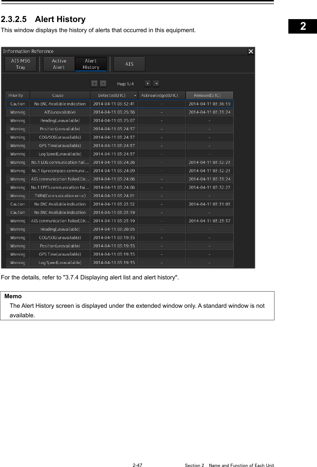
![Section 2 Name and Function of Each Unit 2-40 2.3.2 Information reference windows By clicking on the buttons in the window, the contents that are displayed in the window can be switched. Information reference related windows are listed below. Button Displayed content Related section [AIS MSG Tray] AIS message tray 2.3.2.2 AIS MSG Tray [NAVTEX] (Displayed only when NAVTEX is installed) NAVTEX message 2.3.2.3 NAVTEX [Active Alert] Active alert that occurred in the equipment 2.3.2.4 Active Alert [Alert History] Alert history that occurred in the equipment 2.3.2.5 Alert History [AIS] Own ship’s AIS information 2.3.2.6 AIS [AIS MSG Tray] button [Active Alert] button [Alert History] button [AIS] button [NAVTEX] button](https://usermanual.wiki/Japan-Radio/NKE2632.Instruction-Manual-Operation-Part-2/User-Guide-2791057-Page-40.png)
![2-41 Section 2 Name and Function of Each Unit 1 2 3 4 5 6 7 8 9 10 11 12 13 14 15 16 17 18 19 20 21 22 23 24 25 APP A APP B 1 When unread messages exist The number of unread messages is displayed on the [AIS MSG Tray] button as a badge. 2.3.2.1 Switching between a standard window and an extended window The information reference window can be switched to a standard window or an extended window. To switch to an extended window, click on the List extension button. To switch to a standard window, click on the List Standard button. [Example of extended window] List standard button List extension button](https://usermanual.wiki/Japan-Radio/NKE2632.Instruction-Manual-Operation-Part-2/User-Guide-2791057-Page-41.png)
![Section 2 Name and Function of Each Unit 2-42 [Example of standard window] A list screen and a detail screen are available for the standard window. To switch to the detail screen: Click on the [Detail] button. To switch to the list screen: Click on the [List] button. When the display contents overlap the top, bottom, left, or right side of the screen, a scroll bar is displayed. By dragging the scroll bar, the overlapped section can be displayed. Memo A standard window is displayed at the initial display. When the RADAR transmission status is Transmit in RADAR mode, the extended window cannot be displayed. [Detail] button [List] button Scroll bar Scroll bar](https://usermanual.wiki/Japan-Radio/NKE2632.Instruction-Manual-Operation-Part-2/User-Guide-2791057-Page-42.png)
![Section 2 Name and Function of Each Unit 2-44 2.3.2.3 NAVTEX The NAVTEX message is displayed. [1] NAVTEX message list NAVTEX messages are listed. When a message line is clicked on, the details are displayed in “(2) Message details”. (a) Date Received Displays a message received time. (b) Station ID Displays the message transmission source base station ID (A to Z). [1] [2] (a) (b) (c) (d)](https://usermanual.wiki/Japan-Radio/NKE2632.Instruction-Manual-Operation-Part-2/User-Guide-2791057-Page-44.png)
![2-45 Section 2 Name and Function of Each Unit 1 2 3 4 5 6 7 8 9 10 11 12 13 14 15 16 17 18 19 20 21 22 23 24 25 APP A APP B 1 (c) Message ID Displays the message ID (A to Z). (d) Disp check box When this check box is checked, the symbol is displayed. Sorting a message list When any of the items in the title line is clicked on, the messages are sorted based on the item. [2] Message details (a) Station ID Displays the message transmission source base station ID (A to Z) and the name. (b) Message ID Displays the message ID and name. (c) Expiration Date Set the expiration date of the message. • When the calendar icon is clicked on, a calendar picker is displayed. Set the expiration date by using the calendar picker. • The color of the Expiration Date changes for the expired message. (d) NAVTEX Message A message is displayed. (a) (b) (c) (d)](https://usermanual.wiki/Japan-Radio/NKE2632.Instruction-Manual-Operation-Part-2/User-Guide-2791057-Page-45.png)
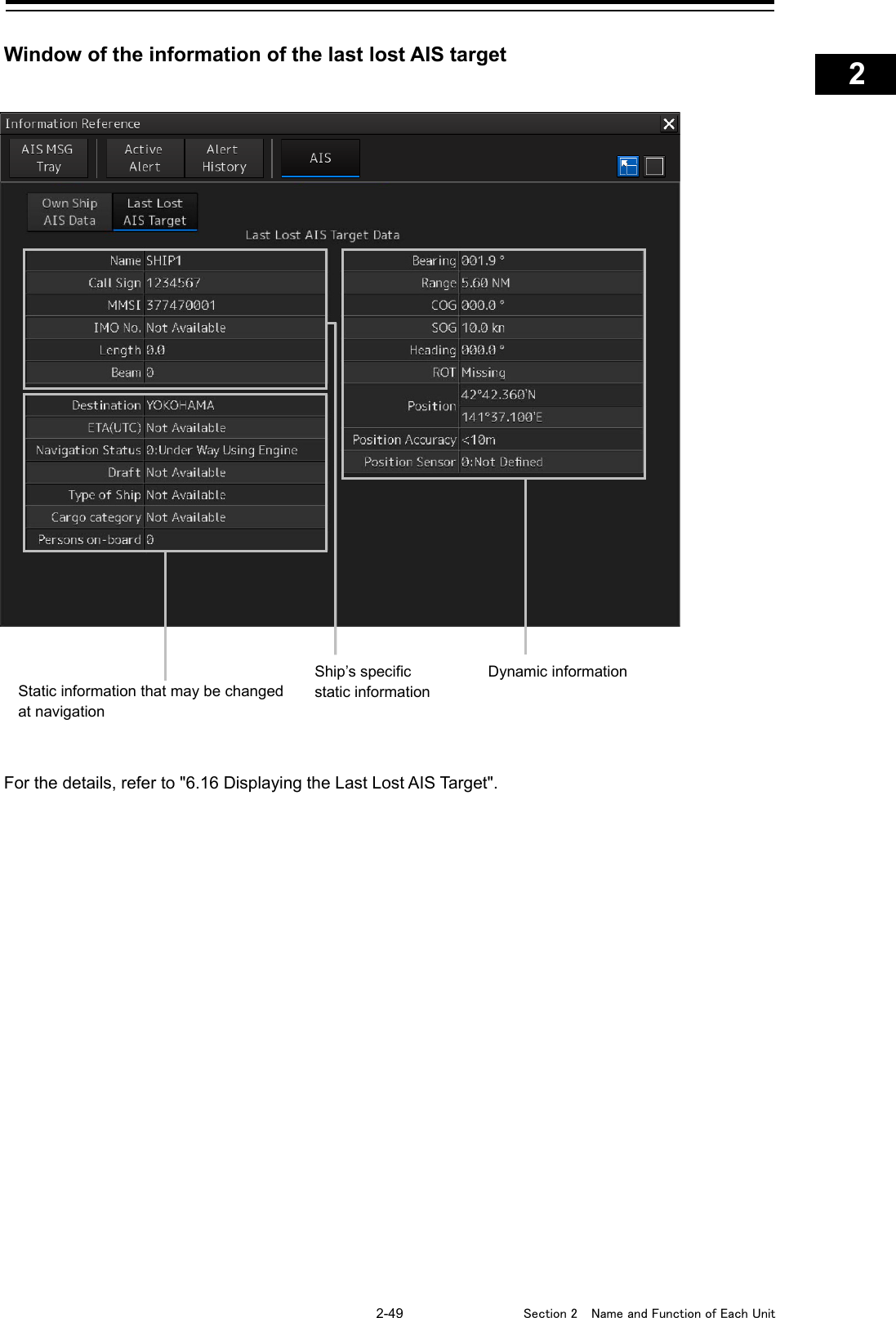
![Section 2 Name and Function of Each Unit 2-48 2.3.2.6 AIS This window displays AIS information. The AIS window includes the "Own Ship AIS Data" window that displays the AIS information of the own ship and "Last Lost AIS Target" window that displays the information of the last AIS target that is lost. Own Ship AIS Data window For the details, refer to "6.15 Confirming Own Ship's AIS Information". When the [Own Ship AIS Data] button is clicked on, the Own Ship AIS Data window is displayed. When the [Last Lost AIS Target] button is clicked on, the information window of the last lost AIS target is displayed. Ship’s specific static information Dynamic information Static information that may be changed at navigation](https://usermanual.wiki/Japan-Radio/NKE2632.Instruction-Manual-Operation-Part-2/User-Guide-2791057-Page-48.png)
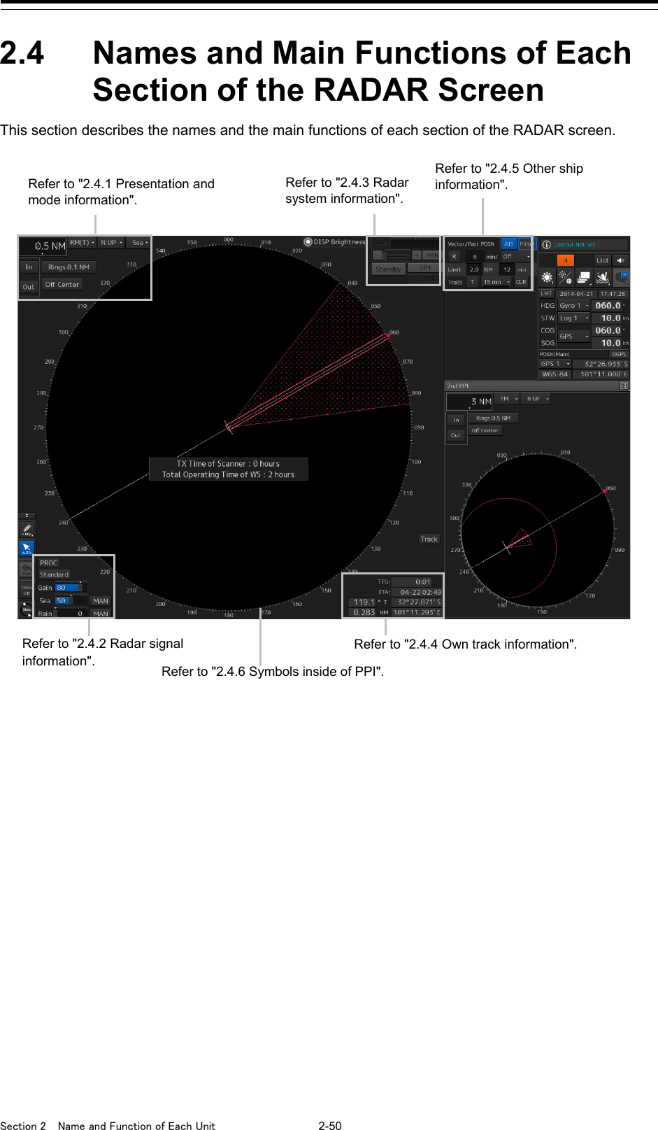
![2-51 Section 2 Name and Function of Each Unit 1 2 3 4 5 6 7 8 9 10 11 12 13 14 15 16 17 18 19 20 21 22 23 24 25 APP A APP B 1 2.4.1 Presentation and mode information Range scale combo box Set the observation range. For the details, refer to "5.3.2 Changing the observation range". Motion mode combo box Set the motion mode. For the details, refer to "5.4.6 Setting a motion mode". Bearing mode combo box Set the bearing mode. For the details, refer to "5.4.5 Setting the azimuth mode". Stabilization mode combo box Set the stabilization mode. For the details, refer to "5.4.7 Setting the Stabilization Mode". [Out] (Zoom Out) button Whenever this button is clicked on, the screen image is zoomed out by one level from the current range scale. When this button is held down, the image is zoomed out continuously. [In] (Zoom In) button Whenever this button is clicked on, the screen image is zoomed in by one level from the current range scale. When this button is held down, the image is zoomed in continuously. Range rings display button Use this button to switch range rings to On/Off. For the details, refer to "4.4 Using the Range Rings". [Off Center] button Use this button to set Off Center to On/Off for the display position of the own ship’s position (CCRP). For the details, refer to "5.4.8 Moving own ship’s display position (Off Center)".](https://usermanual.wiki/Japan-Radio/NKE2632.Instruction-Manual-Operation-Part-2/User-Guide-2791057-Page-51.png)
![Section 2 Name and Function of Each Unit 2-52 2.4.2 Radar signal information RADAR signal processing setting button This button sets RADAR signal processing. When this button is clicked on, a setting dialog box appears. [1] [X2 (Zoom)] button When this button is clicked on, the double scale zoom function is switched to On/Off. For the details, refer to "5.4.10 Doubling the size of radar image". [2] [IR] combo box This setting is enabled to set a radar interference rejection function from the list For the details, refer to "5.4.1 Interference Rejection (IR Function)". [3] [Target Enhance] combo box This setting is enabled to set a target enhancement function from the list For the details, refer to "5.4.3 Enhancing targets". [4] [Echo Process] combo box This setting is enabled to set a video processing function from the list For the details, refer to "5.4.4 Using video processing (Echo Process)". [5] [Chirp Channel] combo box This setting is enabled to set the Chirp Channel function by selecting On or Off from the combo box. *The Chirp Channel function can be set only when a small solid -state radar antenna is connected. By changing the transmission central frequency (channel) of Q0N (Chirp wave: Frequency modulation pulse) that is used for pulse compression, interferences can be controlled. [1] Reception sensitivity adjustment The reception sensitivity can be adjusted. For the details, refer to "5.3.4 Adjusting gain". [2] Sea clutter adjustment The sea clutter rejection level can be adjusted. For the details, refer to "5.3.5 Rejecting sea clutter (Sea)". [3] Rain and snow clutter adjustment The rain and snow clutter rejection level can be adjusted. For the details, refer to "5.3.6 Rejecting rain/snow clutter". Observation Scene Selection button This button sets an observation scene For the details, refer to "5.3.7 Adjusting to optimal images (Selection of observation scenes)". [1] [2] [3] [1] [2] [3] [4] [5]](https://usermanual.wiki/Japan-Radio/NKE2632.Instruction-Manual-Operation-Part-2/User-Guide-2791057-Page-52.png)