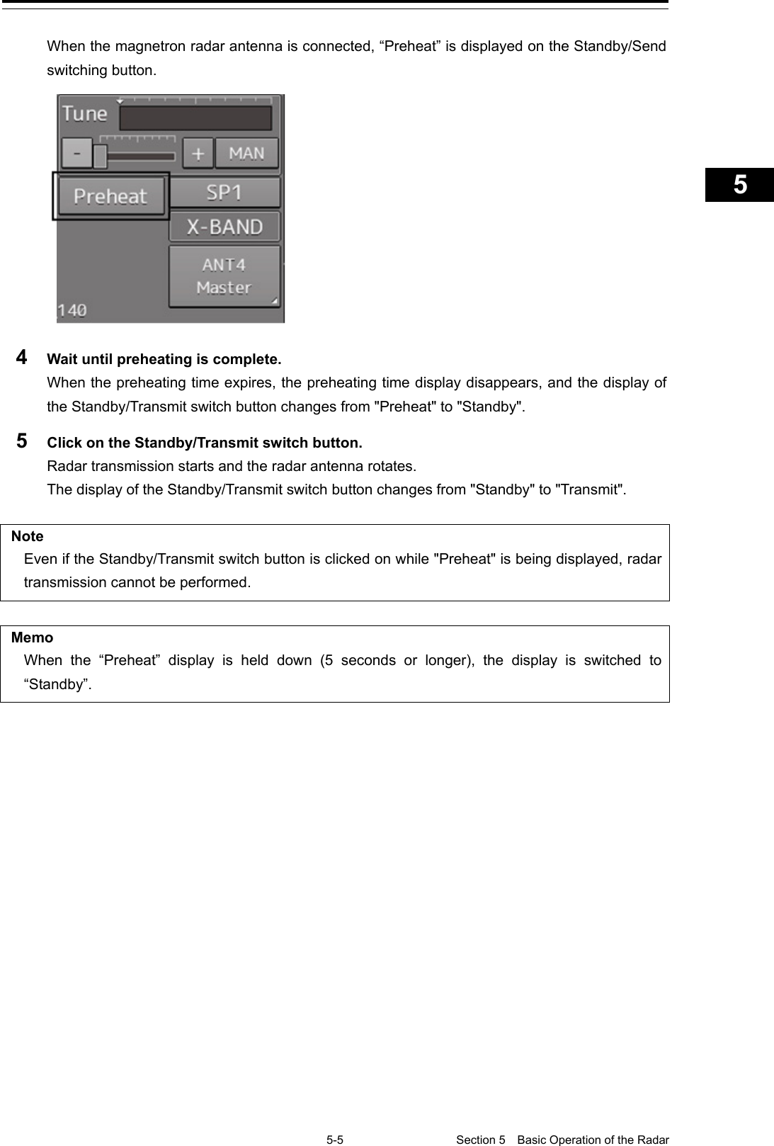
Japan Radio NKE2632 Solid State S-Band Marine Radar User Manual Instruction Manual Funtion Part 1
Japan Radio Co Ltd. Solid State S-Band Marine Radar Instruction Manual Funtion Part 1
Contents
- 1. Installation Manual Part 1
- 2. Installation Manual Part 2
- 3. Installation Manual Part 3
- 4. Installation Manual Part 4
- 5. Installation Manual Part 5
- 6. Installation Manual Part 6
- 7. Installation Manual Part 7
- 8. Installation Manual Part 8
- 9. Installation Manual Part 9
- 10. Installation Manual Part 10
- 11. Installation Manual Part 11
- 12. Instruction Manual Operation Part 1
- 13. Instruction Manual Operation Part 2
- 14. Instruction Manual Operation Part 3
- 15. Instruction Manual Operation Part 4
- 16. Instruction Manual Funtion Part 1
- 17. Instruction Manual Funtion Part 2
- 18. Instruction Manual Funtion Part 3
- 19. Instruction Manual Funtion Part 4
- 20. Instruction Manual Funtion Part 5
- 21. Instruction Manual Funtion Part 6
Instruction Manual Funtion Part 1
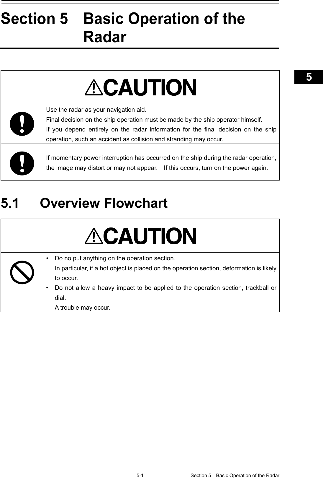
![Overview 1 Name and Function of Each Unit 2 Common Basic Operations 3 Range and Bearing Measurement Methods 4 Basic Operation of the Radar 5 Target Tracking and AIS 6 True and False Echoes on Display 7 Functions of the ECDIS 8 Route Planning 9 Route Monitoring 10 Monitoring a Dragging Anchor 11 Automatic Sailing 12 Operating a Chart 13 Creating a User Map/ Updating a Chart Manually 14 Logbook 15 Setting Up Screen View 16 Setting Up Alerts 17 Setting Up the Operation Mode 18 Adjusting and Setting Up Equipment (for Services) 19 Playing Back Data Recorded During Navigation [Playback] 20 Maintenance & Inspection 21 Failures and After-Sale Services 22 About Disposal 23 Specifications 24 Radar Antenna Block Diagrams APP A Alert List APP B Setting the Interswitch APP C Menu List and Materials APP D JMR-7230-S3/S JMR-7225-7X3/9X3/6X/9X/6XH JMR-7210-6X/6XH JMR-7272-S JMR-7282-S/SH JMR-9230-S3/S JMR-9225-7X3/9X3/6X/9X/6XH JMR-9210-6X/6XH JMR-9272-S JMR-9282-S/SH Marine Radar Equipment Instruction Manual <Function>](https://usermanual.wiki/Japan-Radio/NKE2632.Instruction-Manual-Funtion-Part-1/User-Guide-2791060-Page-1.png)
![㻌㻌㻌(1) Contents 2 3 4 5 6 7 8 9 10 11 12 13 14 15 16 17 18 19 20 21 22 23 24 25 26 27 Contents Function Section 5 Basic Operation of the Radar ....................................................... 5-1 5.1 Overview Flowchart ............................................................................................................... 5-1 5.2 Starting and Shutting Down the Radar .................................................................................. 5-3 5.2.1 Powering on and starting .............................................................................................. 5-3 5.2.2 Exiting radar operation .................................................................................................. 5-6 5.3 Observation Environment and Image Adjustment ................................................................ 5-7 5.3.1 Adjusting screen brightness .......................................................................................... 5-7 5.3.2 Changing the observation range ................................................................................... 5-7 5.3.3 Adjusting tune ............................................................................................................... 5- 9 5.3.4 Adjusting gain ............................................................................................................. 5-10 5.3.5 Rejecting sea clutter (Sea) ......................................................................................... 5-12 5.3.6 Rejecting rain/snow clutter .......................................................................................... 5-14 5.3.7 Adjusting to optimal images (Selection of observation scenes) ................................. 5-16 5.4 General Radar Operation .................................................................................................... 5-19 5.4.1 Interference Rejection (IRFunction) .......................................................................... 5-19 5.4.2 Changing the transmitter pulse length ........................................................................ 5-20 5.4.3 Enhancing targets ....................................................................................................... 5-21 5.4.4 Using video processing (Echo Process) ..................................................................... 5-22 5.4.5 Setting the azimuth mode ........................................................................................... 5-23 5.4.6 Setting a motion mode ................................................................................................ 5-25 5.4.6.1 Resetting Own Ship to its Initial Position in [TM] (True Motion display) Mode ..... 5-26 5.4.7 Setting the Stabilization Mode .................................................................................... 5-27 5.4.8 Moving own ship’s display position (Off Center) ......................................................... 5-27 5.4.9 Displaying other ship’s trails (Trails) ........................................................................... 5-28 5.4.9.1 Trails motion mode ............................................................................................... 5-28 5.4.9.2 Changing motion mode of trails ............................................................................ 5-30 5.4.9.3 Setting the length of the trail ................................................................................. 5-30 5.4.9.4 Clearing trails data ................................................................................................ 5-31 5.4.10 Doubling the size of radar image ................................................................................ 5-32 5.4.11 Hiding the heading line (HL OFF) ............................................................................... 5-34 5.4.12 Hiding graphics information on radar display ............................................................. 5-35 5.4.13 Setting true bearing ..................................................................................................... 5-35 5.4.14 Setting own ship speed ............................................................................................... 5-36 5.4.14.1 Switching own ship speed device ......................................................................... 5-36 5.4.14.2 Entering the ship’s heading/own ship’s speed manually ...................................... 5-38 Section 6 Target Tracking and AIS ............................................................... 6-1 7ZPNA4447A](https://usermanual.wiki/Japan-Radio/NKE2632.Instruction-Manual-Funtion-Part-1/User-Guide-2791060-Page-3.png)
![Contents (2) 6.1 Restrictions ........................................................................................................................... 6-2 6.2 Collision Avoidance Issue (Explanation) ............................................................................... 6-3 6.2.1 Collision Avoidance in Navigation ................................................................................. 6-3 6.2.2 Marine Accidents and Collisions ................................................................................... 6-3 6.2.3 Basic Concept of Collision Avoidance .......................................................................... 6-4 6.2.4 Relative Vector and True Vector ................................................................................... 6-5 6.2.5 Radar and Collision Avoidance ..................................................................................... 6-5 6.3 Displaying Symbols ............................................................................................................... 6-6 6.3.1 Displaying/hiding target tracking symbols/AIS target symbols ..................................... 6-6 6.3.2 Types and Definitions of Target Tracking Symbols ....................................................... 6-6 6.3.3 Types and Definitions of AIS Target Symbols ............................................................... 6-7 6.3.4 About AIS AtoN (Aids to Navigation) ........................................................................... 6-10 6.3.5 About AIS-SART Information ...................................................................................... 6-10 6.3.6 About Display Priority of AIS Targets .......................................................................... 6-10 6.3.7 Switching between Ground Vector and Water Vector ................................................. 6-11 6.3.8 Association Target Symbols ........................................................................................ 6-11 6.4 Preparation .......................................................................................................................... 6-12 6.4.1 Setting the Cursor Mode to AUTO Mode .................................................................... 6-12 6.4.2 Setting Vector .............................................................................................................. 6-12 6.4.2.1 Vector modes ........................................................................................................ 6-12 6.4.2.2 Setting vector mode .............................................................................................. 6-14 6.4.2.3 Vector Length (Vector Time) ................................................................................. 6-14 6.4.2.4 Setting the Vector Length ..................................................................................... 6-15 6.4.3 Setting collision decision criteria ................................................................................. 6-15 6.4.3.1 Setting CPA limit ................................................................................................... 6-15 6.4.3.2 Setting TCPA limit ................................................................................................. 6-16 6.4.4 Showing the CPA ring (RADAR only) ......................................................................... 6-17 6.5 Setting and Operating Target Tracking ............................................................................... 6-18 6.5.1 Acquiring target ........................................................................................................... 6-18 6.5.1.1 Automatic acquisition (automatic acquisition) mode ............................................ 6-18 6.5.1.2 ACQ MANUAL (manual acquisition) mode........................................................... 6-19 6.5.1.3 Using manual acquisition and auto acquisition together ...................................... 6-20 6.5.2 Setting up the automatic acquisition/activation zone (AZ) .......................................... 6-20 6.5.2.1 Using "New Target Warning" dialog box in the [Alert] menu ................................ 6-21 6.5.2.2 Using the cursor ................................................................................................... 6-22 6.5.2.3 Using the EBL/VRM dial for the setting ................................................................ 6-23 6.5.3 Tracked target information display .............................................................................. 6-24 6.5.4 Erasing unwanted tracked targets .............................................................................. 6-25 6.5.5 Displaying Target ID No. ............................................................................................. 6-26 6.5.6 Editing tracked target properties ................................................................................. 6-28 6.5.6.1 Adding Tracked Target ID Name .......................................................................... 6-28 6.5.6.2 Setting track color of tracked target ...................................................................... 6-30 6.5.7 Setting target for which ground is fixed to a reference target ..................................... 6-31](https://usermanual.wiki/Japan-Radio/NKE2632.Instruction-Manual-Funtion-Part-1/User-Guide-2791060-Page-4.png)
![(3) Contents 2 3 4 5 6 7 8 9 10 11 12 13 14 15 16 17 18 19 20 21 22 23 24 25 26 27 6.5.8 Operation Test for Target Tracking .............................................................................. 6-33 6.5.8.1 Test Video ............................................................................................................. 6-34 6.5.8.2 [TT Simulator] (Target tracking simulator) ............................................................ 6-35 6.5.8.3 [Gate Display] ....................................................................................................... 6-37 6.5.8.4 Status display ....................................................................................................... 6-39 6.6 Setting and Operating AIS................................................................................................... 6-40 6.6.1 Enabling AIS Function ................................................................................................ 6-40 6.6.2 Activating AIS targets (Activate AIS) ........................................................................... 6-40 6.6.2.1 Manual activation .................................................................................................. 6-40 6.6.2.2 Automatic activation ............................................................................................. 6-41 6.6.3 Deactivating AIS targets .............................................................................................. 6-41 6.6.4 Displaying AIS information .......................................................................................... 6-42 6.6.5 Displaying Target ID No. ............................................................................................. 6-50 6.6.6 Checking and setting AIS target property ................................................................... 6-51 6.6.6.1 Setting track color of AIS target ............................................................................ 6-51 6.6.7 Conditions for deciding AIS target to be lost ............................................................... 6-52 6.7 Alert Display ........................................................................................................................ 6-53 6.7.1 Danger target alarm (CPA/TCPA) ............................................................................... 6-54 6.7.2 Alarm for new target acquired in automatic acquisition guard zone (New target) ...... 6-55 6.7.3 Lost target notification (Lost) ...................................................................................... 6-56 6.7.4 Target Tracking function alarm (TT Data) ................................................................... 6-57 6.7.5 Gyro set notification (Set Gyro) .................................................................................. 6-57 6.8 Track Function ..................................................................................................................... 6-58 6.8.1 Setting the Past position ............................................................................................. 6-58 6.8.2 Setting the other ship's tracks ..................................................................................... 6-58 6.8.2.1 Setting track color ................................................................................................. 6-59 6.8.2.2 Turning on/off other ship's track function .............................................................. 6-59 6.8.2.3 Setting other ship's track colors ............................................................................ 6-59 6.8.2.4 Turning on/off other ship's track display ............................................................... 6-59 6.8.2.5 Setting up the display interval of other ship’s track .............................................. 6-60 6.8.2.6 Clearing other ship's track .................................................................................... 6-60 6.8.2.7 Saving and loading other ship's track data ........................................................... 6-60 6.9 Entering Own Ship's AIS Voyage Data ............................................................................... 6-61 6.10 Editing and Sending AIS Messages .................................................................................... 6-62 6.11 AIS Message Tray ............................................................................................................... 6-65 6.11.1 Displaying the AIS message tray ................................................................................ 6-65 6.11.2 Switching message display ......................................................................................... 6-67 6.11.3 Sending a message in the message tray after editing ................................................ 6-68 6.12 Highlighting TT/AIS Symbols .............................................................................................. 6-69 6.13 Trial Maneuvering ................................................................................................................ 6-71 6.13.1 Outline of Trial Maneuvering ....................................................................................... 6-71 6.13.2 Performing a trial maneuver ....................................................................................... 6-74](https://usermanual.wiki/Japan-Radio/NKE2632.Instruction-Manual-Funtion-Part-1/User-Guide-2791060-Page-5.png)
![Contents (4) 6.14 Displaying the TT/AIS Target List ........................................................................................ 6-76 6.14.1 Displaying TT/AIS List ................................................................................................. 6-76 6.14.1.1 Switching between a standard window and an extended window ....................... 6-77 6.14.2 TT List ......................................................................................................................... 6-79 6.14.3 AIS List ........................................................................................................................ 6-80 6.15 Confirming Own Ship's AIS Information .............................................................................. 6-82 6.16 Displaying the Last Lost AIS Target .................................................................................... 6-83 Section 7 True and False Echoes on Display .............................................. 7-1 7.1 Radar Wave with the Horizon ............................................................................................... 7-1 7.2 Intensity Reflected from the Target ....................................................................................... 7-3 7.3 Sea Clutter and Rain/Snow Clutter ....................................................................................... 7-5 7.3.1 Sea clutter ..................................................................................................................... 7-5 7.3.2 Rain and snow clutter ................................................................................................... 7-6 7.3.3 Coping with sea clutter and rain/snow clutter ............................................................... 7-8 7.4 False Echoes ........................................................................................................................ 7-9 7.4.1 Shadow ......................................................................................................................... 7-9 7.4.2 Side lobe effect ............................................................................................................. 7-9 7.4.3 False echo by secondary reflection ............................................................................ 7-10 7.4.4 False echo by multiple reflection ................................................................................ 7-11 7.4.5 Second time echoes ................................................................................................... 7-11 7.4.6 Radar interference ...................................................................................................... 7-12 7.5 Radar Transponder (SART) Screen Display ....................................................................... 7-13 7.6 Display of AIS-SART ........................................................................................................... 7-15 7.6.1 Radar screen display example ................................................................................... 7-15 7.6.2 Numeric data display example .................................................................................... 7-16 Section 8 Functions of the ECDIS (Option) ........................................................... 8-1 8.1 General Flowchart ................................................................................................................. 8-1 8.1.1 Work Flowchart While Sailing ....................................................................................... 8-2 8.2 Starting and Preparing the ECDIS ........................................................................................ 8-3 8.2.1 Powering on and starting .............................................................................................. 8-3 8.2.2 Starting the ECDIS ........................................................................................................ 8-4 8.2.2.1 Starting the ECDIS from the Task Menu ................................................................. 8-4 8.2.2.2 Starting ECDIS from a non-ECDIS task screen ..................................................... 8-5 8.2.3 Entering an ARCS PIN Number (ARCS Only) .............................................................. 8-6 8.3 Moving the Chart ................................................................................................................... 8-7 8.3.1 Moving the chart with the [HOME] button ..................................................................... 8-7 8.3.2 Moving the chart with the cross-hair cursor .................................................................. 8-8 8.3.3 Moving the chart with the hand cursor .......................................................................... 8-9 8.3.4 Switching a chart to be displayed by "My Port List" .................................................... 8-10 8.3.5 Displaying the chart by entering the position .............................................................. 8-11 8.4 Zooming In/Out the Chart.................................................................................................... 8-12](https://usermanual.wiki/Japan-Radio/NKE2632.Instruction-Manual-Funtion-Part-1/User-Guide-2791060-Page-6.png)
![(5) Contents 2 3 4 5 6 7 8 9 10 11 12 13 14 15 16 17 18 19 20 21 22 23 24 25 26 27 8.4.1 Enlarging a Selected Area (S-57/C-MAP Only) .......................................................... 8-12 8.4.2 Enlarging/reducing a chart with the Zoom function .................................................... 8-14 8.4.2.1 Enlarging/reducing with the [ZOOM IN]/[ZOOM OUT] key on the trackball operation unit (S-57/C-MAP only)......................................................................... 8-14 8.4.2.2 Enlarging/reducing with the zoom slider (S-57/C-MAP only) ............................... 8-14 8.4.2.3 Enlarging/reducing with the Large/Small buttons (RNC only) .............................. 8-15 8.4.3 Switching between scale and range (S-57/C-MAP only) ............................................ 8-16 8.5 Changing the Object Category (S-57/C-MAP Only)............................................................ 8-17 8.5.1 Switching object display .............................................................................................. 8-18 8.5.2 Customizing object display ......................................................................................... 8-19 8.6 Selecting Motion/Bearing Mode .......................................................................................... 8-21 8.6.1 Setting motion mode ................................................................................................... 8-22 8.6.2 Setting Bearing mode (S-57/C-MAP only) .................................................................. 8-24 8.7 Registering and Displaying My Port List ............................................................................. 8-26 8.7.1 Registering to My Port List .......................................................................................... 8-26 8.7.2 Deleting a port ............................................................................................................. 8-27 8.8 Selecting a S-57 chart ......................................................................................................... 8-28 8.9 Selecting an ARCS chart ..................................................................................................... 8-29 8.9.1 Selecting charts from all .............................................................................................. 8-29 8.9.2 Changing active panels (ARCS only) ......................................................................... 8-30 8.9.3 Changing a low resolution chart (ARCS only) ............................................................ 8-31 8.9.4 Changing a high resolution chart (ARCS only) ............................................................... 8-32 8.9.5 Displaying the note and diagram (ARCS only) ............................................................ 8-33 8.10 Multi View Display and Wide Range View Window Display of Charts ................................ 8-34 8.10.1 Display of multi view ................................................................................................... 8-35 8.10.1.1 Displaying multi view ............................................................................................ 8-35 8.10.1.2 Multi view operation procedure ............................................................................ 8-37 8.11 Verifying Object Information (Pick Report Function) ........................................................... 8-41 8.11.1 Pick Report of the S-57 chart ...................................................................................... 8-41 8.11.1.1 Displaying a Pick Report of the S-57 chart ........................................................... 8-41 8.11.1.2 Verifying Object Information ................................................................................. 8-43 8.11.1.3 Verifying Chart Information ................................................................................... 8-46 8.11.1.4 Verifying Chart Update History ............................................................................. 8-47 8.11.2 Pick report of the ARCS chart ..................................................................................... 8-48 8.11.3 Manual Update Pick Report ........................................................................................ 8-49 8.11.3.1 Displaying a Manual Update Pick Report ............................................................. 8-49 8.12 Marking the Position of Own Ship with an Event Mark ....................................................... 8-50 8.13 Displaying Radar Images on a Chart by Overlaying ........................................................... 8-51 8.13.1 Turning On/Off overlay display ................................................................................... 8-52 8.13.2 Turning On/Off range ring display ............................................................................... 8-54 8.13.3 Turning On/Off bearing scale ...................................................................................... 8-55 8.13.4 Radar image adjustment ............................................................................................. 8-56](https://usermanual.wiki/Japan-Radio/NKE2632.Instruction-Manual-Funtion-Part-1/User-Guide-2791060-Page-7.png)
![Contents (6) 8.14 Setting a true bearing .......................................................................................................... 8-57 8.15 Setting an own ship’s speed ............................................................................................... 8-58 8.15.1 Switching an own ship’s speed sensor ....................................................................... 8-58 8.15.2 Entering the ship’s heading/own ship’s speed manually ............................................ 8-59 Section 9 Route Planning .............................................................................. 9-1 9.1 Overview of the Route Planning Function ............................................................................. 9-2 9.2 Setting Route Display ............................................................................................................ 9-3 9.2.1 Setting [Route] after selecting [View] - [Options] on the menu ..................................... 9-3 9.2.2 Setting [Settings] - [Route] on the menu ....................................................................... 9-5 9.3 Starting and Ending the Route Planning Dialog Box ............................................................ 9-9 9.3.1 Starting the "Route Planning" dialog box ...................................................................... 9-9 9.3.2 Ending the "Route Planning" dialog box ....................................................................... 9-9 9.4 Name and Function of Each Section of the "Route Planning" Dialog Box ......................... 9-10 9.4.1 Route Planning bar ..................................................................................................... 9-10 9.4.2 Route planning tab ...................................................................................................... 9-15 9.5 Saving a Route .................................................................................................................... 9-17 9.6 Planning a Route by Using Table Editing ............................................................................ 9-21 9.6.1 Table editing operation flow ........................................................................................ 9-21 9.6.1.1 Creating a new route file ....................................................................................... 9-21 9.6.1.2 Editing a route ...................................................................................................... 9-22 9.6.2 Creating a new route file by table editing .................................................................... 9-23 9.6.3 Deleting WPT data ...................................................................................................... 9-25 9.6.4 Editing a route by table editing ................................................................................... 9-25 9.6.4.1 Inserting WPT ....................................................................................................... 9-28 9.6.4.2 Deleting WPT ....................................................................................................... 9-28 9.6.4.3 Dividing a leg ........................................................................................................ 9-29 9.6.4.4 Copying the entire route ....................................................................................... 9-29 9.6.4.5 Pasting the route .................................................................................................. 9-30 9.6.4.6 Inserting the other route ....................................................................................... 9-30 9.6.4.7 Insert the same WPT as the last WPT ................................................................. 9-31 9.7 Planning a New Route by Graphic Editing .......................................................................... 9-32 9.7.1 Graphic editing operation flow .................................................................................... 9-32 9.7.1.1 Creating a new route file ....................................................................................... 9-32 9.7.1.2 Editing a route file ................................................................................................. 9-33 9.7.2 Creating a new route file by graphic editing ............................................................... 9-34 9.7.2.1 Creating a route by using EBL/VRM .................................................................... 9-36 9.7.2.2 Creating a route by using the assistant circle function ......................................... 9-38 9.7.3 Editing a route by graphic editing ............................................................................... 9-40 9.7.3.1 Inserting a WPT between WPTs ........................................................................... 9-42 9.7.3.2 Moving a WPT ...................................................................................................... 9-43 9.7.3.3 Changing XTL (cross track limit) .......................................................................... 9-45 9.7.3.4 Adding WPT on the context menu ........................................................................ 9-46](https://usermanual.wiki/Japan-Radio/NKE2632.Instruction-Manual-Funtion-Part-1/User-Guide-2791060-Page-8.png)
![Contents (8) 11.1.1 Setting a dragging anchor monitoring circle ............................................................... 11-2 11.1.2 Setting a dragging anchor monitoring polygon ........................................................... 11-3 11.2 Starting and Ending Dragging Anchor Monitoring ............................................................... 11-5 11.2.1 Starting dragging anchor monitoring ........................................................................... 11-5 11.2.2 Ending dragging anchor monitoring ............................................................................ 11-6 11.3 Moving/Editing/Deleting a Dragging Anchor Monitoring Area on the Chart ........................ 11-7 11.3.1 Moving a dragging anchor monitoring circle on the chart ........................................... 11-7 11.3.2 Moving a dragging anchor monitoring circle on the context menu ............................. 11-8 11.3.3 Moving a dragging anchor monitoring polygon on the chart ...................................... 11-8 11.3.4 Moving a dragging anchor monitoring ploygon on the context menu ......................... 11-8 11.3.5 Changing a size of a dragging anchor monitoring circle on the chart ........................ 11-9 11.3.6 Changing a size of a dragging anchor monitoring circle on the context menu ......... 11-10 11.3.7 Changing a shape of a dragging anchor monitoring polygon on the chart ............... 11-10 11.3.8 Changing a shape of a dragging anchor monitoring polygon on the context menu .. 11-11 Section 12 Automatic Sailing (Option) ................................................................. 12-1 12.1 Flow of Starting Automatic Sailing ....................................................................................... 12-2 12.2 Selecting a Route ................................................................................................................ 12-6 12.2.1 Using the existing planned route ................................................................................ 12-6 12.2.2 Creating a new route .................................................................................................. 12-8 12.3 Selecting a Waypoint at which Automatic Sailing Starts ................................................... 12-10 12.4 Starting Automatic Sailing ................................................................................................. 12-12 12.5 Stopping Automatic Sailing ............................................................................................... 12-14 12.6 Alerts at Automatic Sailing ................................................................................................ 12-15 Section 13 Operating a Chart (option) .............................................................. 13-1 13.1 Updating a Chart Manually.................................................................................................. 13-3 13.2 Displaying/Searching an S-57 Chart [Select S-57 Chart] ................................................... 13-4 13.2.1 Displaying a chart ....................................................................................................... 13-4 13.2.2 Search a chart ............................................................................................................. 13-5 13.2.2.1 Searching the position that is clicked on by the cursor ........................................ 13-5 13.2.2.2 Searching by using a chart name ......................................................................... 13-6 13.3 Displaying a Chart by Inputting a Position .......................................................................... 13-7 13.4 Confirming/Accepting an S-57 Updated Chart .................................................................... 13-8 13.5 Displaying a Date-dependent Object .................................................................................. 13-9 13.6 Displaying a Chart Boundary ............................................................................................ 13-10 13.6.1 Setting a boundary to be displayed on the chart ...................................................... 13-10 13.6.2 Displaying chart information ..................................................................................... 13-11 13.7 Confirming Temporary/Preliminary Information of an ARCS Chart (ARCS Only) ............. 13-12 13.8 Adjusting an ARCS Chart Position (ARCS Only) .............................................................. 13-13 13.8.1 Offsetting an ARCS chart .......................................................................................... 13-13 13.8.2 Transforming a geodetic datum of an ARCS chart to WGS-84 ................................ 13-15](https://usermanual.wiki/Japan-Radio/NKE2632.Instruction-Manual-Funtion-Part-1/User-Guide-2791060-Page-10.png)
![Contents (10) 14.3.5 Displaying the object/redisplaying the hidden object ................................................ 14-29 14.4 How to Use the Map Creation Tools (for Manual Update) ................................................ 14-30 14.4.1 Deleting or hiding an object ...................................................................................... 14-30 14.4.2 Selecting an object type ............................................................................................ 14-31 14.5 Creating an Object ............................................................................................................ 14-32 14.5.1 Creating a symbol object (Symbol) ........................................................................... 14-33 14.5.1.1 Creating an object by specifying the latitude and longitude ............................... 14-33 14.5.1.2 Creating an object with EBL/VRM operation ...................................................... 14-34 14.5.2 Creating a simple line and a Warning line (Line object) ........................................... 14-35 14.5.2.1 Creating a vertex by entering the position .......................................................... 14-38 14.5.2.2 Creating an object with EBL/VRM operation ...................................................... 14-38 14.5.3 Creating a circle, ellipse, and an arc (Line object) .................................................... 14-40 14.5.3.1 Creating an object by specifying a position for the center and size of the object .................................................................................................................. 14-42 14.5.4 Creating a polygon and a Warning area (Area object) ............................................. 14-43 14.5.4.1 Creating a vertex by entering the position .......................................................... 14-45 14.5.4.2 Creating an object with EBL/VRM operation ...................................................... 14-46 14.5.5 Creating circle, ellipse, and fan areas (Area object) ................................................. 14-47 14.5.5.1 Creating an object by specifying the center position and the object size ........... 14-49 14.5.6 Creating a text (Text object) ...................................................................................... 14-50 14.5.6.1 Creating a text by specifying the latitude and longitude ..................................... 14-51 14.5.6.2 Creating a text with EBL/VRM operation ............................................................ 14-51 14.5.6.3 Editing a text ....................................................................................................... 14-52 14.5.6.4 Editing a template ............................................................................................... 14-52 14.5.6.5 Changing a text angle ......................................................................................... 14-54 14.5.7 Creating an arrow (Line object) ................................................................................ 14-55 14.5.7.1 Creating an object by specifying the starting point/ending point position coordinates ......................................................................................................... 14-56 14.5.7.2 Drawing an object with EBL/VRM operation ...................................................... 14-57 14.5.8 Creating Mariner's Mark/Line drawing objects (ECDIS screen only) ........................ 14-58 14.5.8.1 Information mark ................................................................................................. 14-58 14.5.8.2 Clearing line ........................................................................................................ 14-60 14.5.8.3 Tidal Stream mark ............................................................................................... 14-63 14.5.8.4 Highlighted display ............................................................................................. 14-65 14.6 Collective Deletion of Objects [Delete by Type/Color] ...................................................... 14-71 14.7 Managing/Editing Objects [Mark Line/List] ........................................................................ 14-72 14.7.1 Displaying the "Mark/Line List" dialog box ................................................................ 14-72 14.7.2 Displaying a user map list ......................................................................................... 14-73 14.7.2.1 Displaying an object on a chart .......................................................................... 14-73 14.7.2.2 Deleting an object ............................................................................................... 14-74 14.7.3 Displaying a Mariner's Mark/Line List (ECDIS screen only) ..................................... 14-74 14.7.3.1 Displaying an object on a chart .......................................................................... 14-74 14.7.3.2 Deleting an object ............................................................................................... 14-74](https://usermanual.wiki/Japan-Radio/NKE2632.Instruction-Manual-Funtion-Part-1/User-Guide-2791060-Page-12.png)
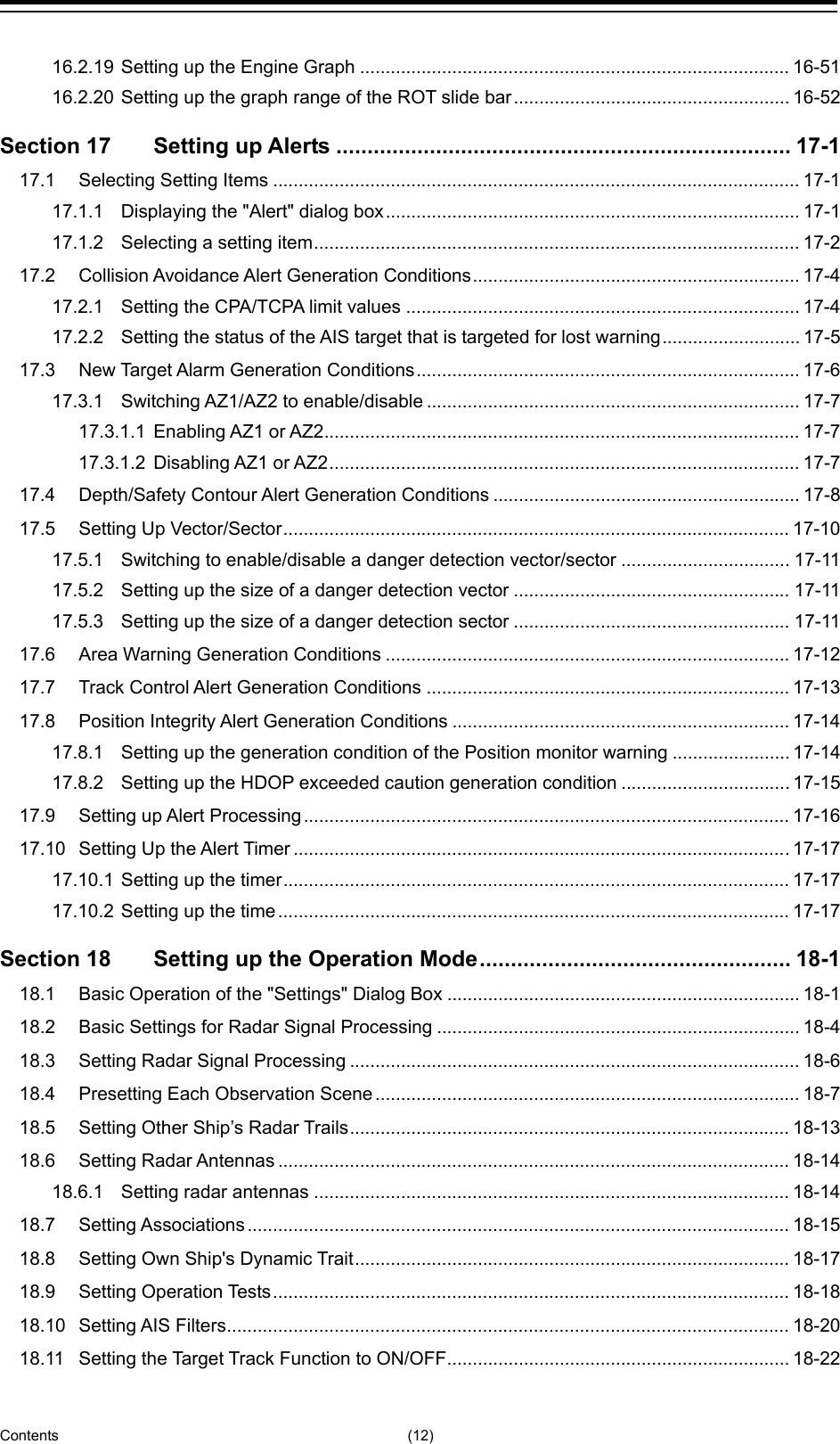

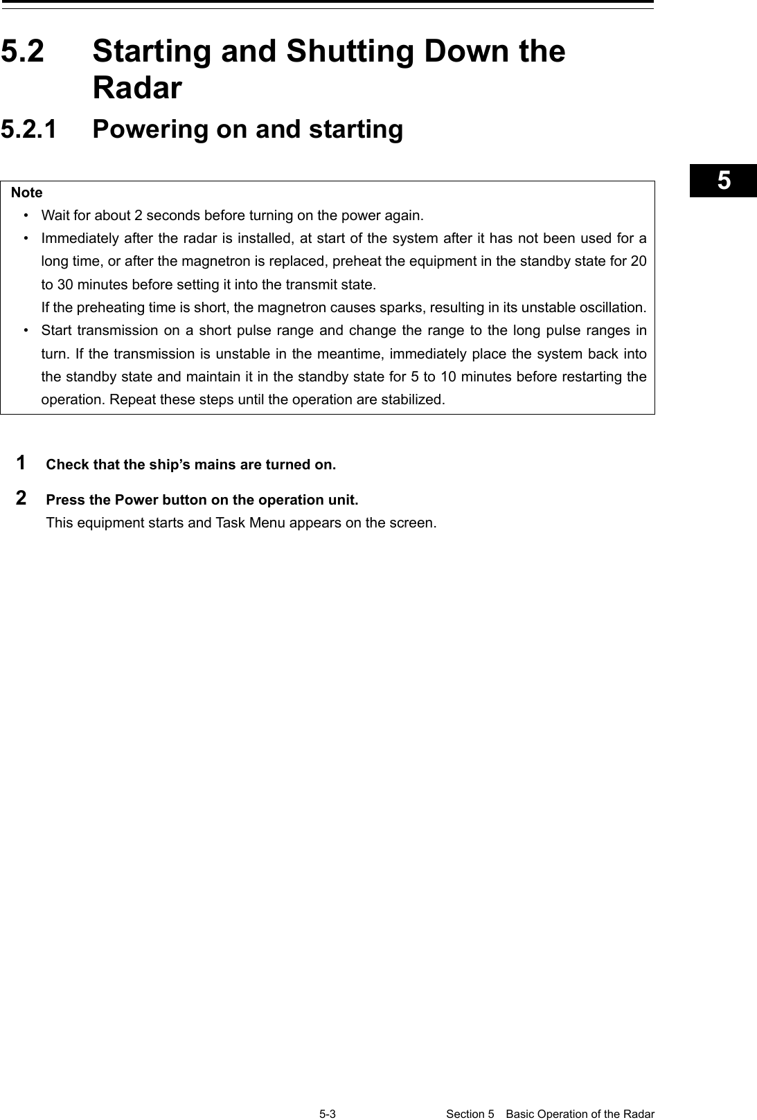
![Section 5 Basic Operation of the Radar 5-4 3 Click on the [Collision Avoidance (RADAR)] button on Task Menu. The RADAR screen appears. The preheating time is displayed at the center of the screen. Preheating time](https://usermanual.wiki/Japan-Radio/NKE2632.Instruction-Manual-Funtion-Part-1/User-Guide-2791060-Page-20.png)
![5-7 Section 5 Basic Operation of the Radar 1 2 3 4 5 5 7 8 9 10 11 12 13 14 15 16 17 18 19 20 21 22 23 24 25 APP A APP B 1 5.3 Observation Environment and Image Adjustment 5.3.1 Adjusting screen brightness 1 Adjust the screen brightness. For the details of the adjustment, refer to "3.9 Adjusting the Brightness of the Screen and Operation Unit". In consideration of the ambient brightness, adjust the brightness of the display that is high enough to easily observe the radar display but does not glare. 5.3.2 Changing the observation range 1 Click on the Range Scale button in Presentation and mode information, and then select Range from the pop-up menu. [Points on adjustments] Increasing the observation range will enable a wider range to be observed. However, a video image is small and the ability to detect targets near own ship decreases. Therefore, when observing the vicinity of own ship, use the smaller observation range. Decreasing the observation range will enable the vicinity of own ship to be enlarged. However, caution must be taken because video images of the area beyond the observation range cannot be displayed. Range Scale button](https://usermanual.wiki/Japan-Radio/NKE2632.Instruction-Manual-Funtion-Part-1/User-Guide-2791060-Page-23.png)
![5-9 Section 5 Basic Operation of the Radar 1 2 3 4 5 5 7 8 9 10 11 12 13 14 15 16 17 18 19 20 21 22 23 24 25 APP A APP B 1 5.3.3 Adjusting tune Normally, use the automatic tune mode. If you use the manual tuning mode, an accident may be caused by fluctuation of transmission and reception. Use the manual tune mode only when best tuning is not possible in the automatic tune mode due to deterioration of magnetron. This equipment has the automatic tuning mode that performs tuning of the transmission frequency and the reception frequency by automatic control, and the manual tuning mode in which the user performs tuning. Normally use the automatic tune mode. Only when the best tuning is not possible by the automatic tune mode due to the deterioration of magnetron, use the manual tune mode. The tuning mode currently being used is displayed on the Tuning Mode button in Radar system information. Note This function is effective when a magnetron radar antenna is connected. When using the automatic tune mode 1 Click on the tune mode button. [AUTO] (automatic) is displayed on the tune mode button. Whenever the button is clicked on, the mode is switched between [AUTO] (automatic) and [MAN] (manual). Tuning Mode button](https://usermanual.wiki/Japan-Radio/NKE2632.Instruction-Manual-Funtion-Part-1/User-Guide-2791060-Page-25.png)
![Section 5 Basic Operation of the Radar 5-10 Using the manual tune mode 1 Click on the tune mode button. [MAN] (manual) is displayed on the tune mode button. Each time this button is clicked on, the display switches between [AUTO] (automatic) and [MAN] (manual). 2 Move the fine tuning slider to the left and right sides. The tuning status is displayed on the tuning bar according to the movement of the fine tuning slider. Make adjustments so that the display on the tuning bar indicates the maximum (the state in which the tuning bar is positioned at the most right). 5.3.4 Adjusting gain Be sure to always adjust for the best gain. If the gain is too high, undesired signals including receiver noise and false echoes increase resulting in reduction of visibility of targets. Otherwise, accidents may result. On the contrary, if the gain is too low, targets including ships and dangerous objects may not be clearly indicated. Adjust the gain of the radar. Memo Set the optimum gain when making adjustments, giving consideration to the setting described in "5.3.7 Adjusting to optimal images (Selection of observation scenes)". This bar indicates the tuning state. Tuning indication peak line Indicates the maximum point of tuning. Fine tuning slider](https://usermanual.wiki/Japan-Radio/NKE2632.Instruction-Manual-Funtion-Part-1/User-Guide-2791060-Page-26.png)
![5-11 Section 5 Basic Operation of the Radar 1 2 3 4 5 5 7 8 9 10 11 12 13 14 15 16 17 18 19 20 21 22 23 24 25 APP A APP B 1 1 Drag the [Gain] (reception gain adjustment) slider dial in Radar signal information, turn the trackball, and set up reception gain. Moving the slider to the right increases gain. Moving the slider to the left decreases gain. The current reception gain level is indicated by the bar and a numeric value. [Points on adjustments] As reception gain is increased, the range in which radar images can be observed widens; however, if gain is increased too high, receiver noise, false echoes and other undesired signals will increase on the screen, lowering the visibility of targets. Also, it gets easier to see the screen display if gain is decreased to observe cluttered targets and close range, but be careful not to overlook small targets. Memo If the optimal setting value was lost, it is recommended to reset to the initial value and tune up again. The initial setting value is indicated as shown in the figure at right. Initial setting value [Gain] (reception gain adjustment) slider Current reception gain](https://usermanual.wiki/Japan-Radio/NKE2632.Instruction-Manual-Funtion-Part-1/User-Guide-2791060-Page-27.png)
![Section 5 Basic Operation of the Radar 5-12 5.3.5 Rejecting sea clutter (Sea) Never set the sea clutter suppression function before rejecting all the sea clutters at close range. Detection of not only echoes from the wave and so on but also targets such as other ships or dangerous objects may be suppressed. When using the sea clutter suppression function, make sure to choose the most appropriate setting for suppression. Memo Remove images by sea clutter by using the sea clutter suppression function. When using the sea clutter suppression function, make the optimum setting, giving considerating to the setting described in "5.3.7 Adjusting to optimal images (Selection of observation scenes)". 1 Drag the [Sea] (sea clutter adjustment) slider dial in Radar signal information, turn the trackball, and adjust the amount of images by sea clutter displayed on the screen so as to make display easy to observe. Moving the slider to the right decreases the amount of images by sea clutter. Moving the slider to the left increases the amount of images by sea clutter. The current level of sea clutter suppression is indicated by the bar and a numeric value. [Points on adjustments] The sea clutter suppression function decreases the amount of images by sea clutter by lowering reception gain at close range. When reception gain is lowered, the effectiveness of sea clutter suppression increases; however, if excessive effect is applied, please note that targets having weak signal strength such as buoys and small ships will disappear. [Sea] (sea clutter adjustment) slider Current level of sea clutter suppression](https://usermanual.wiki/Japan-Radio/NKE2632.Instruction-Manual-Funtion-Part-1/User-Guide-2791060-Page-28.png)
![5-13 Section 5 Basic Operation of the Radar 1 2 3 4 5 5 7 8 9 10 11 12 13 14 15 16 17 18 19 20 21 22 23 24 25 APP A APP B 1 Memo If the optimal setting value was lost, it is recommended to reset to the initial value and tune up again. The initial setting value is indicated as shown in the figure at right. Using the function of automatic sea clutter suppression mode The sea clutter suppression in accordance with the intensity of sea clutter is possible. Use this mode when the sea clutter's intensity differs according to directional orientation. 1 Click on the Automatic Sea Clutter Suppression button. [AUTO] (automatic) is displayed on the automatic sea clutter suppression button. Each time this button is clicked on, the display switches between [AUTO] (automatic) and [MAN] (manual). 2 Drag the sea clutter adjustment slider dial, turn the trackball, and adjust the amount of images by sea clutter displayed on the screen. Even while automatic sea clutter is being suppressed, the amount of images can be fine-adjusted manually. Canceling automatic sea clutter suppression 1 Click on the Automatic Sea Clutter Suppression button. [MAN] (manual) is displayed on the automatic sea clutter suppression button. Each time this button is clicked on, the display switches between [AUTO] (automatic) and [MAN] (manual). Initial setting value Auto Sea Clutter Suppression button](https://usermanual.wiki/Japan-Radio/NKE2632.Instruction-Manual-Funtion-Part-1/User-Guide-2791060-Page-29.png)
![Section 5 Basic Operation of the Radar 5-14 5.3.6 Rejecting rain/snow clutter Never set the rain/snow clutter suppression function too high. Detection of not only echoes from the rain or snow but also images targets such as other ships or dangerous objects may be suppressed. When using the rain/snow clutter suppression function, make sure to choose the most appropriate setting for suppression. Memo Remove images by rain/snow clutter by using the sea clutter suppression function. When using the rain/snow clutter suppression function, make the optimum setting giving considerating to the setting described in "5.3.7 Adjusting to optimal images (Selection of observation scenes)". 1 Drag the [Rain] rain/snow clutter adjustment slider dial in Radar signal information, turn the trackball, and adjust the amount of images by rain/snow clutter displayed on the screen so as to make display easy to observe. [Rain] (rain/snow clutter adjustment) slider](https://usermanual.wiki/Japan-Radio/NKE2632.Instruction-Manual-Funtion-Part-1/User-Guide-2791060-Page-30.png)
![5-15 Section 5 Basic Operation of the Radar 1 2 3 4 5 5 7 8 9 10 11 12 13 14 15 16 17 18 19 20 21 22 23 24 25 APP A APP B 1 Moving the slider to the right decreases the amount of images by rain/snow clutter. Moving the slider to the left increases the amount of images by rain/snow clutter. The current level of rain/snow clutter suppression is indicated by the bar and a numeric value. [Points on adjustments] When the amount of images by rain/snow clutter is decreased, the outlines of targets hidden by images of rain/snow will appear, but please note that small targets may be missed. Since this can also reduce sea clutter, it is effective to use it together with the sea clutter rejection function. Normally, set the level of rain/snow clutter suppression to 0. Memo If the optimal setting value was lost, it is recommended to reset to the initial value and tune up again. The initial setting value is indicated as shown in the figure at right. Using the automatic rain/snow clutter suppression mode The rain/snow clutter suppression in accordance with the intensity of rain/snow clutter is possible. Use this mode when the rain/snow clutter's intensity differs according to directional orientation. 1 Click on the Automatic Rain/Snow Clutter Suppression button. [AUTO] (automatic) is displayed on the automatic rain/snow clutter suppression button. Each time this button is clicked on, the display switches between [AUTO] (automatic) and [MAN] (manual). 2 Click the left mouse button of the button on the [Rain] (rain/snow clutter adjustment) slider, drag it with the trackball, and adjust the volume of the echo created by rain/snow clutter that is displayed on the screen. Even while auto rain/snow clutter is being suppressed, the amount of images can be fine-adjusted manually. Initial setting value Current level of rain/snow clutter suppression Auto Rain/Snow Clutter Suppression button](https://usermanual.wiki/Japan-Radio/NKE2632.Instruction-Manual-Funtion-Part-1/User-Guide-2791060-Page-31.png)
![Section 5 Basic Operation of the Radar 5-16 Canceling automatic rain/snow clutter suppression 1 Click on the Automatic Rain/Snow Clutter Suppression button. [MAN] (manual) is displayed on the automatic rain/snow clutter suppression button. Each time this button is clicked on, the display switches between [AUTO] (automatic) and [MAN] (manual). 5.3.7 Adjusting to optimal images (Selection of observation scenes) To obtain optimal images, it is necessary to understand the features of radar signal processing settings and perform adjustment according to the sea condition. When adjusting all setting values manually, such adjustment may sometimes difficult even for experienced operators. Thus, signal processing settings suitable for general usage are preset in the observation scene selection function at the time of factory shipment. In many cases, optimal images can be obtained quickly by selecting the observation scene corresponding to the current sea condition. 1 Click on the Observation Scene Selection button in Radar signal information. The "Observation Scene Selection" dialog is displayed. Observation Scene Selection button](https://usermanual.wiki/Japan-Radio/NKE2632.Instruction-Manual-Funtion-Part-1/User-Guide-2791060-Page-32.png)
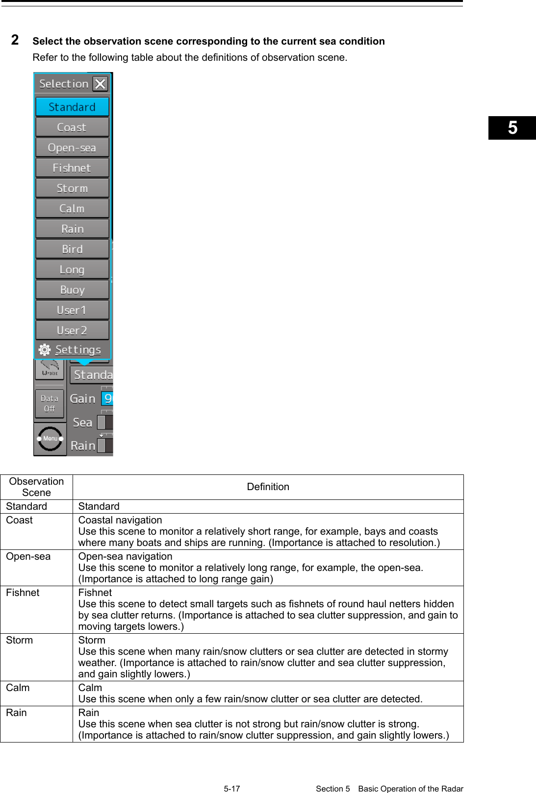
![Section 5 Basic Operation of the Radar 5-18 Observation Scene Definition Bird Bird Use this scene to detect a flock of sea birds. Long Long distance detection Use this scene to monitor utmost distances in the broad ocean. Buoy Buoy Use this scene to detect small targets such as radio buoys outside of sea clutter. (Targets having low detection probability are displayed.) User1 User 1 General scene used when the nine scenes above are not applicable. User2 User 2 General scene used when the nine scenes above are not applicable. 3 Adjust [Gain], [Sea] and [Rain] as necessary. Note When the setting value among the observation scene is changed from the initial value, underline is displayed for the observation scene selection button and a button corresponding to the "Selection" (observation scene selection) dialog is displayed. Memo If the optimal setting value was lost, it is recommended to reset to the initial value and tune up again. The initial setting value is indicated as shown in the figure at right. Initial setting value](https://usermanual.wiki/Japan-Radio/NKE2632.Instruction-Manual-Funtion-Part-1/User-Guide-2791060-Page-34.png)
![5-19 Section 5 Basic Operation of the Radar 1 2 3 4 5 5 7 8 9 10 11 12 13 14 15 16 17 18 19 20 21 22 23 24 25 APP A APP B 1 5.4 General Radar Operation 5.4.1 Interference Rejection (IR Function) By setting IR (Interference Rejection) function, Interference by other radars is rejected. Note To observe the radar beacon and the SART signal, IR processing may occasionally suppress these images, so set IR to Off (interference rejection function OFF). 1 Click on the RADAR Signal Processing Setting button in Radar signal information. The RADAR Process dialog box appears. 2 Click on [IR] and then select the interference rejection level from the list. Setting items Functions and effects [Off] Sets the IR function to Off. [IR Low] Sets the IR level to the low level. [IR Middle] Sets the IR level to the middle level. [IR High] Sets the IR level to the high level. [Points on setting] When a high interference rejection level is selected, the radar’s ability of detecting small targets such as buoys and small boats is lower. In general, [IR Low] should be selected. Radar signal processing setting button](https://usermanual.wiki/Japan-Radio/NKE2632.Instruction-Manual-Funtion-Part-1/User-Guide-2791060-Page-35.png)
![Section 5 Basic Operation of the Radar 5-20 5.4.2 Changing the transmitter pulse length 1 Click on the Transmitter Pulse Length switch button in Radar signal information. Each time this button is clicked on, the transmitter pulse length changes. Transmitter pulse length Functions and effects Recommended condition for selection [SP] The transmitter pulse becomes shorter, and the range resolution improves. The effect of suppressing sea clutter and rain/snow clutter improves. In bays/harbors where targets are densely crowded Rough sea state due to torrential rain or stormy weather [MP] The normal transmitter pulse length is set. Both range resolution and gain are appropriately set. General navigation [LP] The transmitter pulse becomes longer, and gain improves. Small targets are zoomed and are easy to observe. When the sea state is bad, detection performance decreases. Detection of small targets in good weather conditions Memo Usable transmitter pulse length differs according to the type of radar antenna being used and the observation range being used. Transmitter pulse length switch button. Example: [MP1] → [MP2] → [LP1] → [LP2]](https://usermanual.wiki/Japan-Radio/NKE2632.Instruction-Manual-Funtion-Part-1/User-Guide-2791060-Page-36.png)
![5-21 Section 5 Basic Operation of the Radar 1 2 3 4 5 5 7 8 9 10 11 12 13 14 15 16 17 18 19 20 21 22 23 24 25 APP A APP B 1 5.4.3 Enhancing targets This function enlarges the display sizes of images to enhance targets. 1 Click on the RADAR Signal Processing Setting button in Radar system information. The “RADAR Process” dialog box appears. 2 Select the target enhancement level from the list in [Target Enhance]. Setting items Functions and effects Recommended use condition [ENH Off] Sets the target enhancement function to OFF. Set this function to Off when resolution is particularly necessary. [ENH Level1] Enhances the radar echo by 1 level in the vertical and horizontal directions of the screen. Normal navigation [ENH Level2] Enhances the radar echo by 2 levels in the vertical and horizontal directions of the screen. Enhance the visibility of the radar image [ENH Level3] Enhances the radar echo by 3 levels in the vertical and horizontal directions of the screen. Detect small targets such as buoys [Setting points] When [ENH Level3] is selected, sea clutter and rain/snow clutter are apt to be enlarged. To use, suppress images of sea clutter and rain/snow clutter using the [Sea] (sea clutter adjustment) slider and the [Rain] (rain/snow clutter adjustment) slider. In general, [ENH Level1] or [ENH Level2] should be selected. Radar signal processing setting button](https://usermanual.wiki/Japan-Radio/NKE2632.Instruction-Manual-Funtion-Part-1/User-Guide-2791060-Page-37.png)
![Section 5 Basic Operation of the Radar 5-22 5.4.4 Using video processing (Echo Process) This function reduces undesirable noise and enhances targets. Note • When viewing a radar beacon, SART signal, or fast moving target on the radar display, select [Process Off] (video process off). • If video processing mode is set to [CORREL], a high speed target is less-visible . 1 Click on the RADAR Signal Processing Setting button in Radar signal information. The RADAR Process dialog box appears. 2 Select the video process mode from the list in [Echo Process]. Radar signal processing setting button](https://usermanual.wiki/Japan-Radio/NKE2632.Instruction-Manual-Funtion-Part-1/User-Guide-2791060-Page-38.png)
![5-23 Section 5 Basic Operation of the Radar 1 2 3 4 5 5 7 8 9 10 11 12 13 14 15 16 17 18 19 20 21 22 23 24 25 APP A APP B 1 Setting items Effects and recommended use conditions [Process Off] Sets the image processing function to Off. [3 Scan CORREL] Use when the rain/snow clutter images are heavy. [4 Scan CORREL] Use when enhancing the target while suppressing sea clutter images. [5 Scan CORREL] Use when detecting small targets in sea clutter images. [Remain] Use when own ship is rolling severely. [Peak Hold] Use for detection of small targets of low detection probability. 5.4.5 Setting the azimuth mode Set the bearing for the radar video to be displayed on the radar display. 1 Click on the Azimuth mode combo box in Presentation and mode information. 2 Select the Azimuth mode. Note Available combinations vary depending on the settings of the azimuth mode and the motion mode (refer to "5.4.6 Setting a motion mode".). Azimuth mode Motion mode N UP H UP C UP W UP C UP (Angle Setting) TM × × RM(T) or RM(R) Azimuth Mode combo box](https://usermanual.wiki/Japan-Radio/NKE2632.Instruction-Manual-Funtion-Part-1/User-Guide-2791060-Page-39.png)
![Section 5 Basic Operation of the Radar 5-24 The following azimuth modes can be set. Setting items Description Display image [N UP] North UP (North Up) • The video is displayed so that the zenith of the PPI points to the due north. • Fixed targets do not flicker and are easily identified on the chart, and the true bearing of a target can easily be read out. [H UP] Head UP (Head Up) • The video is displayed so that the ship’s heading line is displayed at the top of the screen. Since targets are displayed in their directions relative to the ship’s heading line, the operator can view the video in the same field of view as in operating the ship at sea. Therefore, This mode is suitable for watching over other ships • This is not available for TM (True Motion) mode. [C UP] Course UP (Course Up) • At the setting of Course Up, the ship’s heading (HDG) is fixed and displayed immediately above the screen. Similar to true bearing display, the positions of stationary targets will not deviate even if yawing occurs in the ship: targets are displayed stably and the bearing of the heading line moves only according to the amount of change in own ship's course. To change the course, select the Course UP display by clicking on the Azimuth mode combo box several times. A course can be set again. [W UP] Way Point UP (Waypoint Up) • The destination is displayed at the top of the screen. [C UP (Angle Setting)] Course UP by angle setting (Course Up by angle setting) • When C UP is selected, the "C UP (Angle Setting)" dialog box is displayed. The course angle that is set in the dialog box is displayed by being fixed at the top of the screen. - Input the angle of the ship’s heading in the [Angle] input box of the "C UP (Angle Setting)" dialog box. - The angle can also be input (increase/decrease) by operating the angle input slider. - After completing the setting, click on the [X] button. North North](https://usermanual.wiki/Japan-Radio/NKE2632.Instruction-Manual-Funtion-Part-1/User-Guide-2791060-Page-40.png)
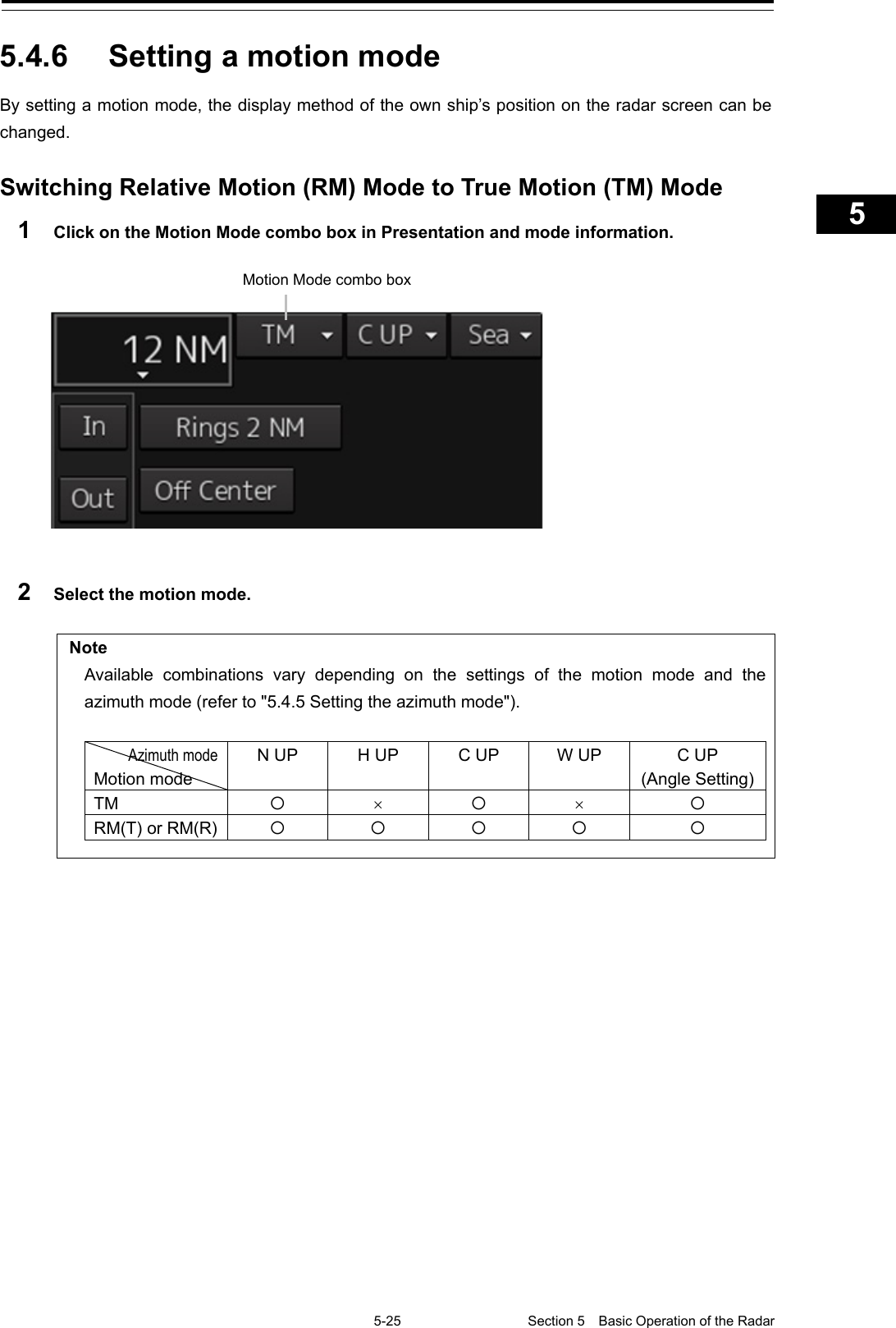
![Section 5 Basic Operation of the Radar 5-26 Setting items Description Display image [TM] True Motion Mode (True Motion display) • In Ground mode, the own ship’s display position moves according to the Speed Over the Ground (SOG) and fixed targets such as land are fixed on the radar screen. • In Water mode, the own ship’s display position moves according to the Speed Through Water (STW) and fixed targets such as land move according to the difference between the Speed Through Water (STW) and the Speed Over the Ground (SOG). • When the own ship reaches to the true motion status, the own ship’s position is set at the position of about 60% of the screen radius in direction opposite to the own ship’s course by adding the influence of the tidal current. The ship’s position starts to move according to the own ship’s speed, course, and influence of the tidal current. When the own ship’s position reaches the position of about 60% of the screen radius, the position is reset to the position of about 66% of the screen radius in the direction opposite to the own ship’s course (COG) by adding the influence of the tidal current at that time. [RM(T)] or [RM(R)] Relative Motion Mode (Relative Motion display) • Own ship is fixed at the center of the radar screen and fixed targets such as land move relatively. [TM Reset] TM Reset • The own ship’s position is reset in [TM] (true motion display) mode. For the details, refer to "5.4.6.1 Resetting Own Ship to its Initial Position in [TM] (True Motion display) Mode". 5.4.6.1 Resetting Own Ship to its Initial Position in [TM] (True Motion display) Mode 1 Select [TM Reset] from the Motion Mode. Own ship is reset to its initial position as established when the relative motion mode is changed to the true motion mode. The ship starts moving from that position. Fixed on the radar display Moving depending on own ship's speed](https://usermanual.wiki/Japan-Radio/NKE2632.Instruction-Manual-Funtion-Part-1/User-Guide-2791060-Page-42.png)
![5-27 Section 5 Basic Operation of the Radar 1 2 3 4 5 5 7 8 9 10 11 12 13 14 15 16 17 18 19 20 21 22 23 24 25 APP A APP B 1 5.4.7 Setting the Stabilization Mode 1 Click on the Stabilization Mode button in Presentation and mode information 2 Select the Stabilization Mode. [GND]: Use the ship speed relative to ground in the Stabilization Mode. [Sea]: Use the ship speed relative to water in the Stabilization Mode. 5.4.8 Moving own ship’s display position (Off Center) The own ship’s position can be moved from the display center to any position within 60% of the display radius. This function is convenient for observing a wide coverage in any direction. Note This function is not available on the 96 NM range. 1 Click on the [Off Center] button in Presentation and mode information to turn the Off Center mode to "On". The Off Center mode is switched to On/Off whenever the button is clicked on. Off Center mode is On: Off Center mode is Off: The cursor mode is set to the Off Center mode. Stabilization Mode combo box](https://usermanual.wiki/Japan-Radio/NKE2632.Instruction-Manual-Funtion-Part-1/User-Guide-2791060-Page-43.png)
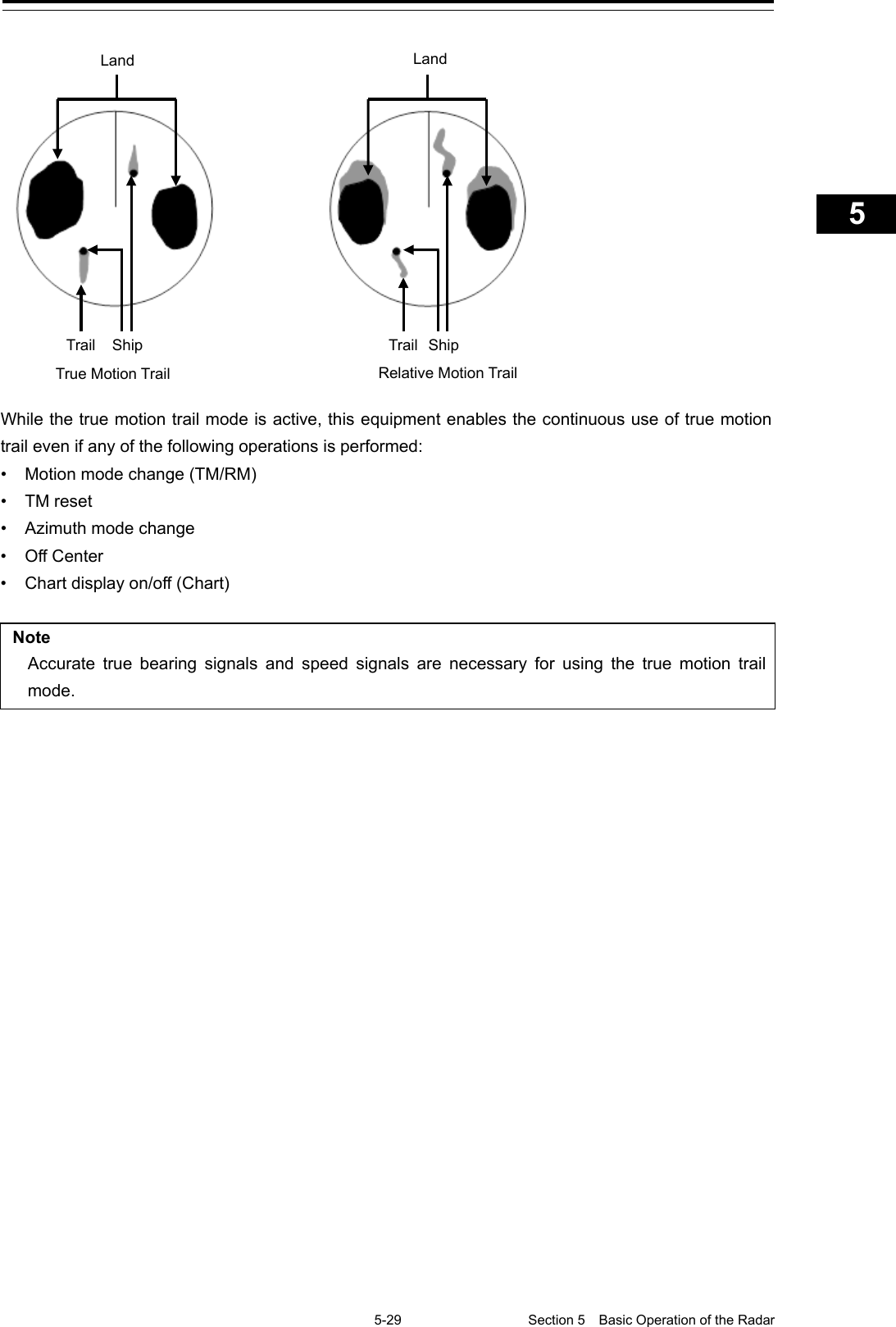
![Section 5 Basic Operation of the Radar 5-28 2 Place the cursor on the position you want to move and click on it. Own ship’s display position will be moved to the clicked position. Note An own ship display position can be moved within the range in which the own ship display position and the antenna position do not exceed 60% of the screen radius. Returning own ship’s position to the center of the display 1 Click on the [Off Center] button in Presentation and mode information to disable the Off Center mode. The own ship position is returned to the center of the display (on relative motion) or the position to be reset (on true motion). 5.4.9 Displaying other ship’s trails (Trails) Other ships’ movements and speeds can be monitored from the lengths and directions of their trails, serving for collision avoidance. 5.4.9.1 Trails motion mode There are two types of trails: relative motion trail and true motion trail. Relative motion trail: The system plots the trails of a target at a position relative to the own ship. The operator can easily judge whether the target is approaching the own ship. While the own ship is moving, the system also plots the trails of land and other fixed targets. True motion trail: The system plots the absolute motion trails of a target, irrespective of the own ship’s position. The operator can easily judge the course and speed of the target. The system does not plot the trails of land and other fixed targets. HL Clicking fixes own ship's position. HL Position the cursor on the destination.](https://usermanual.wiki/Japan-Radio/NKE2632.Instruction-Manual-Funtion-Part-1/User-Guide-2791060-Page-44.png)
![Section 5 Basic Operation of the Radar 5-30 5.4.9.2 Changing motion mode of trails The trail display mode can be switched by using the Trail true/relative switching button of other ship information. Note The available trail motion modes vary depending of the motion mode that is set. True motion display (TM): Only true motion trail is available. Relative motion display (RM): Relative motion trail and true motion trail can be selected. [RM(R)] is displayed when relative motion trail is used. [RM(T)] is displayed when true motion trail is used. 1 Click on the Trails True/Relative switch button. Each time this button is clicked on, the display mode of Trails switches between [T] and [R]. [T]: (True motion trail) [R]: (Relative motion trail) Foe the details of the motion mode of trails, refer to "5.4.9.1 Trails motion mode". 5.4.9.3 Setting the length of the trail 1 Click on the Trail Length switch combo box in [Trails] of other ships' information. Select a radar trail length. Short mode: Off, 15 sec, 30 sec, 1 min, 3 min, 6 min, 10 min, 15 min, 30 min, 60 min Long mode: Off, 30 min, 1 hr, 2 to 24 hrs (at 1 hr interval from 1 to 24 hrs)](https://usermanual.wiki/Japan-Radio/NKE2632.Instruction-Manual-Funtion-Part-1/User-Guide-2791060-Page-46.png)
![5-31 Section 5 Basic Operation of the Radar 1 2 3 4 5 5 7 8 9 10 11 12 13 14 15 16 17 18 19 20 21 22 23 24 25 APP A APP B 1 Memo Saved trails cannot be erased even when the trail lengths are changed the Trail Length switch combo box. Even after the trails display is turned off once, the past trails can be displayed traced back by setting a desired time. The plot of the trail starts when starting the transmission. The system is plotting trails even while the trails display is off. If only a short time has elapsed after the commencement of transmission, the display may not reach the specified value. The time not to reach is indicated by the length of the blue bar shown at the lower part of the Trail Length switch combo box. 5.4.9.4 Clearing trails data 1 Click on the [CLR] (clear trails) button. The confirmation dialog box appears. 2 Click on the [OK] button. All the saved trails data will be cleared. The system starts plotting trails in initial state. CLR (clear trails) button.](https://usermanual.wiki/Japan-Radio/NKE2632.Instruction-Manual-Funtion-Part-1/User-Guide-2791060-Page-47.png)
![Section 5 Basic Operation of the Radar 5-32 5.4.10 Doubling the size of radar image This function doubles the size of radar video near a specified position. Note If the range is 0.125 NM and the motion mode is in the TM mode, this function is not available. 1 Click on the radar signal process setting button in Radar signal information. "RADAR Process" dialog box appears. 2 Click on the [X2(Zoom)] (double zoom) button. Each time this button is clicked on, the double zoom function is switched On and Off. On display: Off display: When double zoom is set, the cursor mode changes to the off-set cursor. Radar signal process setting button](https://usermanual.wiki/Japan-Radio/NKE2632.Instruction-Manual-Funtion-Part-1/User-Guide-2791060-Page-48.png)
![5-33 Section 5 Basic Operation of the Radar 1 2 3 4 5 5 7 8 9 10 11 12 13 14 15 16 17 18 19 20 21 22 23 24 25 APP A APP B 1 3 Place the offset cursor on a location you want to zoom and click on it. Using the cursor position as the reference, the screen display is enlarged by a magnification of 2 so that the midpoint between the cursor and own ship's position comes at the center of the radar display. Canceling zoom display 1 Click on the [X2(Zoom)] button to turn the X2 Zoom function Off. Off display: Cursor mark Own ship's position Cursor mark Center of radar display Own Ship's Position before Zooming Position Own Ship's Position after Zooming Position](https://usermanual.wiki/Japan-Radio/NKE2632.Instruction-Manual-Funtion-Part-1/User-Guide-2791060-Page-49.png)
![Section 5 Basic Operation of the Radar 5-34 5.4.11 Hiding the heading line (HL OFF) 1 Click on the disclosure button on the left toolbar. When the left toolbar is set to expanded display, this operation is not required. 2 The ship’s heading line is hidden while the [HL Off] button is pressed down. When the button is released, the ship’s heading line is redisplayed.](https://usermanual.wiki/Japan-Radio/NKE2632.Instruction-Manual-Funtion-Part-1/User-Guide-2791060-Page-50.png)
![5-35 Section 5 Basic Operation of the Radar 1 2 3 4 5 5 7 8 9 10 11 12 13 14 15 16 17 18 19 20 21 22 23 24 25 APP A APP B 1 5.4.12 Hiding graphics information on radar display On the radar screen of this equipment, various types of graphics information such as TT/AIS symbol, user map, and chart information are displayed. When the visibility of the radar screen deteriorates due to excessive amount of graphic information displayed, the visibility of the screen can be improved by temporarily clearing the unnecessary graphic information by using this function. 1 While the [Data OFF] button on the left toolbar is being held down, graphic information other than the TT and AIS of danger targets, radar images, radar trails and cross cursors are hidden. When the button is released, graphics information is redisplayed. 5.4.13 Setting true bearing When the GYRO I/F is used to enter a gyro signal, there is a rare case in which a true bearing value indicated by the master gyro does not match the true bearing value indicated by this equipment. In that case, adjust the true bearing value of this system so that it matches the value indicated by the master gyro. 1 Click on the [Menu] button on the left toolbar. A menu is displayed. 2 Click [Settings] - [General] on the menu. The [General] dialog box appears.](https://usermanual.wiki/Japan-Radio/NKE2632.Instruction-Manual-Funtion-Part-1/User-Guide-2791060-Page-51.png)
![Section 5 Basic Operation of the Radar 5-36 3 Click on the input box of [GYRO Setting]. 4 Input a master gyro value on the software keyboard. 5.4.14 Setting own ship speed 5.4.14.1 Switching own ship speed device 1 Select the ship speed device from the STW Source combo box in the own ship information.](https://usermanual.wiki/Japan-Radio/NKE2632.Instruction-Manual-Funtion-Part-1/User-Guide-2791060-Page-52.png)
![Section 5 Basic Operation of the Radar 5-38 5.4.14.2 Entering the ship’s heading/own ship’s speed manually If any device such as LOG, etc., connected to this equipment malfunctions, it is possible to manually enter own ship’s heading/speed by the method described below to use the target tracking (TT) and true motion display functions. 1 Select [Menu] from the corresponding combo box. The [Sensor Selection/Status] dialog box is displayed. 2 When inputting a ship’s heading manually, select [MAN] from the [Heading] combo box. To input an own ship speed manually, select [MAN] from the [STW] combo box. 3 Click on the input box. 4 Enter a numeric value by using the software keyboard.](https://usermanual.wiki/Japan-Radio/NKE2632.Instruction-Manual-Funtion-Part-1/User-Guide-2791060-Page-54.png)
![Section 6 Target Tracking and AIS 6-6 6.3 Displaying Symbols This section describes the symbols that are used for target tracking and AIS. 6.3.1 Displaying/hiding target tracking symbols/AIS target symbols In the display setting at the time of shipment from the factory, the display of target tracking symbols and of the AIS target symbols is enabled. However, choosing [Options] – [Target] from the View menu can switch between display and hide. For the details, refer to "16.2.7 Setting up the display of TT/AIS target". 6.3.2 Types and Definitions of Target Tracking Symbols Symbol Definition Remarks Initial acquisition target This symbol is displayed until the vector is displayed after target acquisition. Target acquired in automatic acquisition zone The alarm sounds. The alarm message (New Target) turns orange and blinks. The symbol turns red and blinks. Tracked target This means a tracked target. Dangerous target The alarm sounds. The alarm message (CPA/TCPA) turns red and blinks. The symbol is enlarged and displayed in red. Numeric displayed target When the numeric data is displayed, the target symbol is enclosed in a square. Lost target The alarm sounds. The alarm message (Lost) turns orange and blinks. The symbol turns red. Past position The past positions of an AIS target are displayed as well as the target tracking symbol. Target track The track of another ship as an AIS target is displayed as well as the target tracking symbol. 12 12 12 12 251659264 12 12 12 12](https://usermanual.wiki/Japan-Radio/NKE2632.Instruction-Manual-Funtion-Part-1/User-Guide-2791060-Page-60.png)
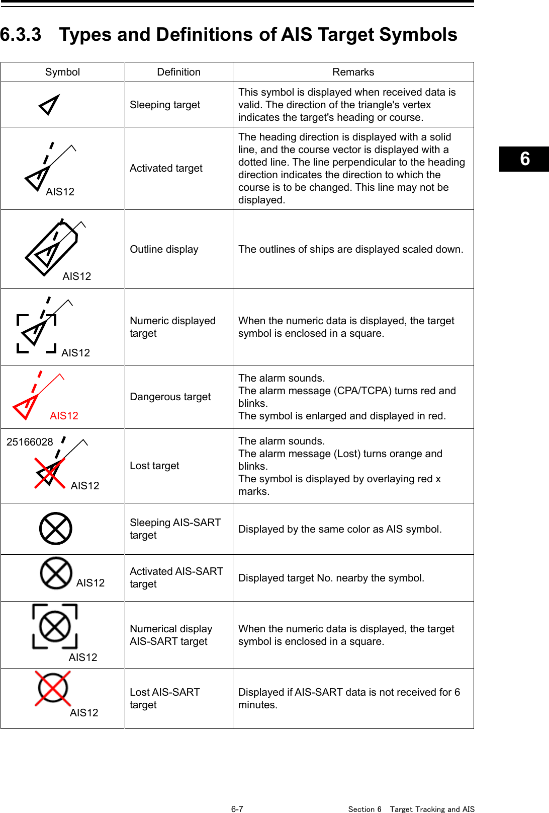
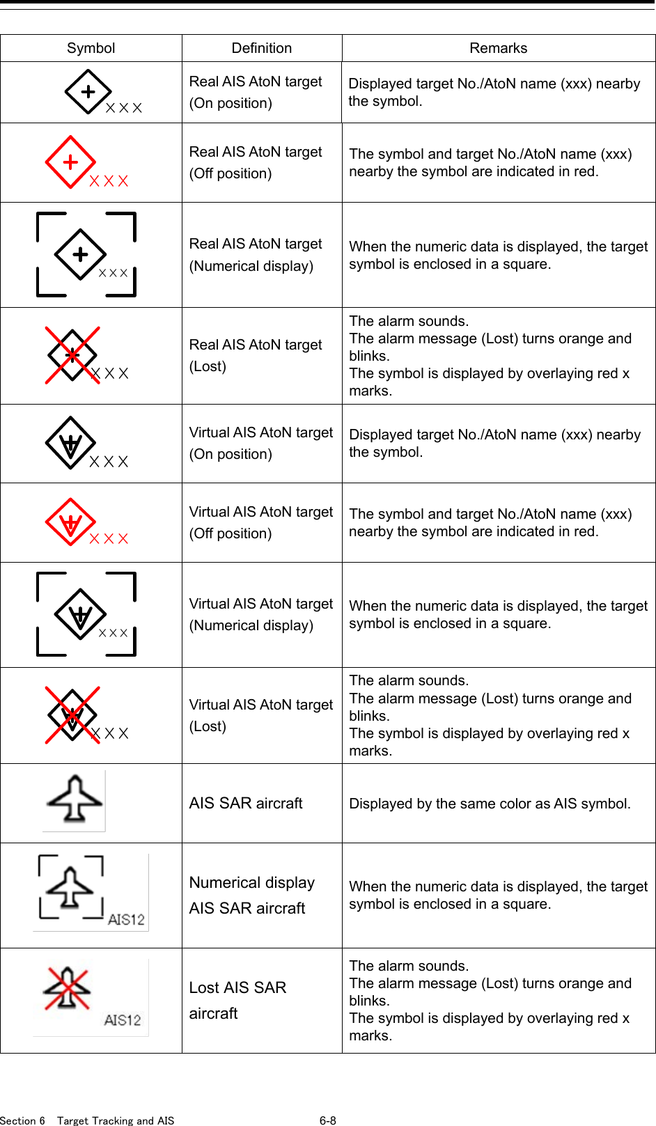
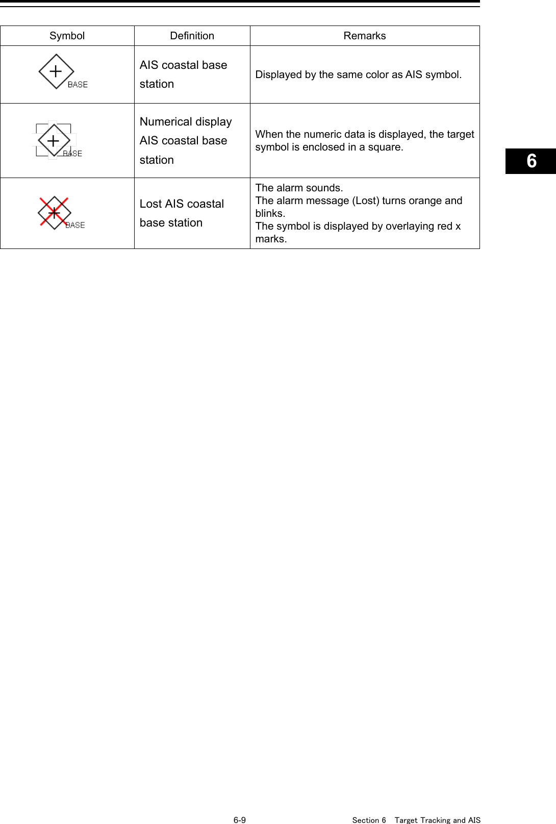
![6-11 Section 6 Target Tracking and AIS 1 2 3 4 5 6 7 8 9 10 11 12 13 14 15 16 17 18 19 20 21 22 23 24 25 26 27 6.3.7 Switching between Ground Vector and Water Vector The vector of an AIS target is to be displayed with a vector over ground or over water by switching the stabilization mode. The type of the currently displayed vector can be confirmed by viewing the setting of the stable mode. When [GND] is selected for the stabilization mode: Ground vector When [Sea] is displayed for the stabilization mode: Water vector When the vector of an AIS target is displayed with a vector over water, the system has converted the AIS target's vector over ground to the vector over water according to the data received from the AIS and the own ship's information. 6.3.8 Association Target Symbols When the TT target and AIS target are determined to be the same targets, the association symbols are displayed as follows. Symbol display for high-priority TT targets Symbol display for high-priority AIS targets When the TT target and AIS target are determined to be the same targets, the TT target or AIS target that are displayed on a higher priority basis can be set. 1 Right-click on the tracked target with association displayed. The context menu appears. 2 Click on [Property] in the context menu. The "TT Target INFO" or "AIS Target INFO" dialog appears. 3 Select [AIS] or [TT] from the [Priority] combo box. [AIS]: The AIS target is displayed on a higher priority basis. [TT]: The TT target is displayed on a higher priority basis. Association targets Association targets](https://usermanual.wiki/Japan-Radio/NKE2632.Instruction-Manual-Funtion-Part-1/User-Guide-2791060-Page-65.png)
![Section 6 Target Tracking and AIS 6-12 6.4 Preparation 6.4.1 Setting the Cursor Mode to AUTO Mode If the cursor mode is set to the AUTO mode, various TT/AIS functions can be executed quickly. 1 Click on the [AUTO] (cursor mode selection) button on the left toolbar. The cursor mode changes to the AUTO mode. The [AUTO] mode performs operation in accordance with the object at the cursor position when clicked. For the details, refer to "3.12 Cursor AUTO Mode". 6.4.2 Setting Vector A vector to represent a target's predicted position can be presented in the True vector or Relative vector mode. In each mode, a Vector Length can be freely changed for a time interval of 1 to 120 minutes. 6.4.2.1 Vector modes Different vector modes can be used as described below according to the purpose. To perceive the true state of the target: True Vector To perceive the closest approach point of the target: Relative Vector](https://usermanual.wiki/Japan-Radio/NKE2632.Instruction-Manual-Funtion-Part-1/User-Guide-2791060-Page-66.png)
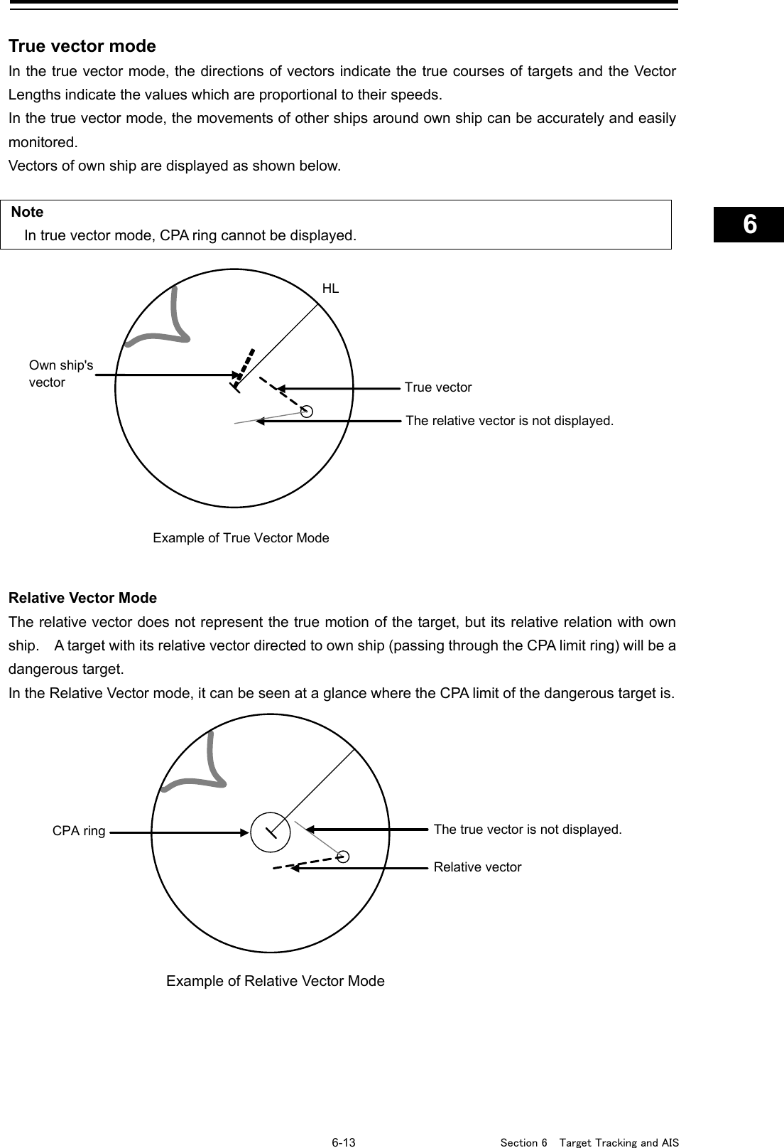
![Section 6 Target Tracking and AIS 6-14 6.4.2.2 Setting vector mode 1 Click on the trail true/relative selector button in the other ship information window. Each click switches track display mode between [T] and [R]. 6.4.2.3 Vector Length (Vector Time) The Vector Length of a target is proportional to its speed, and the vector time can be switched in a range of 1 to 120 minutes. The following figure shows an example in which the Vector Length is set to 6 min, and the tip of the vector represents the target's position expected to reach 6 minutes later. HL Current position Future predicted position (6 min later in this example) Example of Vector Length Trail true/relative selector button](https://usermanual.wiki/Japan-Radio/NKE2632.Instruction-Manual-Funtion-Part-1/User-Guide-2791060-Page-68.png)
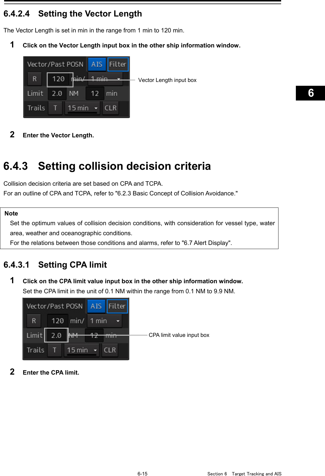
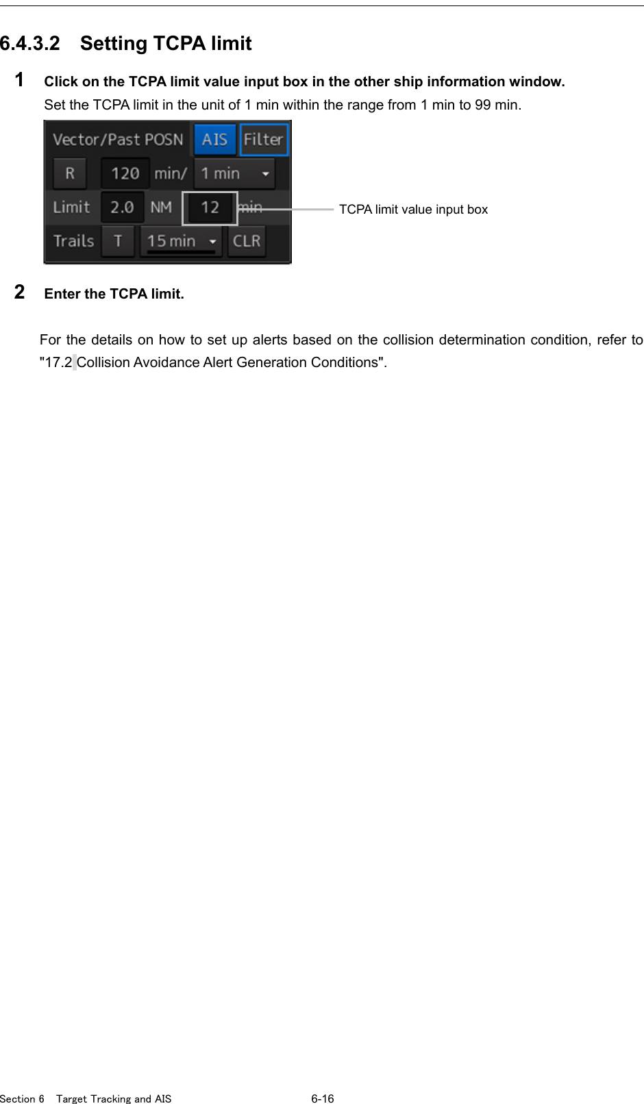
![6-17 Section 6 Target Tracking and AIS 1 2 3 4 5 6 7 8 9 10 11 12 13 14 15 16 17 18 19 20 21 22 23 24 25 26 27 6.4.4 Showing the CPA ring (RADAR only) The CPA ring is rendered as a red circle with the own ship centered and the CPA limit set distance used as the radius. 1 Click on the [Menu] button on the left toolbar. The menu is displayed. 2 Click on [View] - [Option] - [Target]. The [Target] dialog is displayed. 3 Select [CPA Ring (Only Relative mode)]. The CPA ring is shown. Note: When True is specified for the vector mode, [CPA Ring (Only Relative mode)] cannot be selected. [CPA Ring (Only Relative mode)]](https://usermanual.wiki/Japan-Radio/NKE2632.Instruction-Manual-Funtion-Part-1/User-Guide-2791060-Page-71.png)
![Section 6 Target Tracking and AIS 6-18 6.5 Setting and Operating Target Tracking The Target Tracking function automatically tracks the acquired targets and records and displays the course and speed of the targets as vector. Alerts can also be output based on the set collision decision criteria (CPA and TCPA). Note At power off and during preparation for transmission, tracking data records are deleted. 6.5.1 Acquiring target The methods for acquiring targets include Auto Acquisition (automatic acquisition) mode and ACQ MANUAL (manual acquisition) mode. Both modes can also be used concurrently. 6.5.1.1 Automatic acquisition (automatic acquisition) mode By setting up and enabling the automatic acquisition/activation zone (AZ), targets intruding into the AZ can automatically be acquired/tracked and also issue a new target warning. Note If manual acquisition is made in a state in which the number of targets being tracked has reached the maximum number of targets, the target with the lowest danger level among the targets that have been captured thus far automatically is erased successively. Take the following steps to enable automatic acquisition/activation zone (AZ). 1 Click on the [Menu] button on the left toolbar. The menu is displayed. 2 Click [Alert] - [New Target Alarm] on the menu. The "New Target Alarm" dialog is displayed.](https://usermanual.wiki/Japan-Radio/NKE2632.Instruction-Manual-Funtion-Part-1/User-Guide-2791060-Page-72.png)
![6-19 Section 6 Target Tracking and AIS 1 2 3 4 5 6 7 8 9 10 11 12 13 14 15 16 17 18 19 20 21 22 23 24 25 26 27 3 Check [Use AZ1] (automatic acquisition zone 1) or [Use AZ2] (automatic acquisition zone 2). Automatic acquisition/activation zone (AZ) includes AZ1 and AZ2. To enable AZ1, check [Use AZ1]. To enable AZ2, check [Use AZ2]. Memo For the details of "New Target Alarm" dialog box, refer to "17.3 New Target Alarm Generation Conditions". To automatic acquisition/activation zone (AZ): Clear the check of [Use AZ1] or [Use AZ2]. The AZ can also be enabled/disabled with the [AZ] key on the keyboard operation unit. For the details of function assignment to the [AZ] key, refer to "18.20 Setting Key Assignment". 6.5.1.2 ACQ MANUAL (manual acquisition) mode Note The manual acquisition mode does not function in the following states. State Action to Take The number of tracked targets has reached the maximum count. Erase unnecessary targets. The radar antenna is in the standby state. Wait until the radar antenna becomes ready. A PROC (Interrupt) warning is being generated. Clear the warning. A Gyro (I/F)/Gyro (Data)/Heading (Data) warning is being generated. The tracked target is located 32 NM away from own ship. The manual acquisition mode cannot be used. The tracked target is located less than 0.1 NM from own ship. To acquire the tracked target in the manual acquisition mode 1 Set the cursor mode to the AUTO mode. 2 Place the cursor on the target to be acquired and then click on. The target is acquired and the initial acquisition symbol is displayed. The vector is displayed within 1 minute.](https://usermanual.wiki/Japan-Radio/NKE2632.Instruction-Manual-Funtion-Part-1/User-Guide-2791060-Page-73.png)
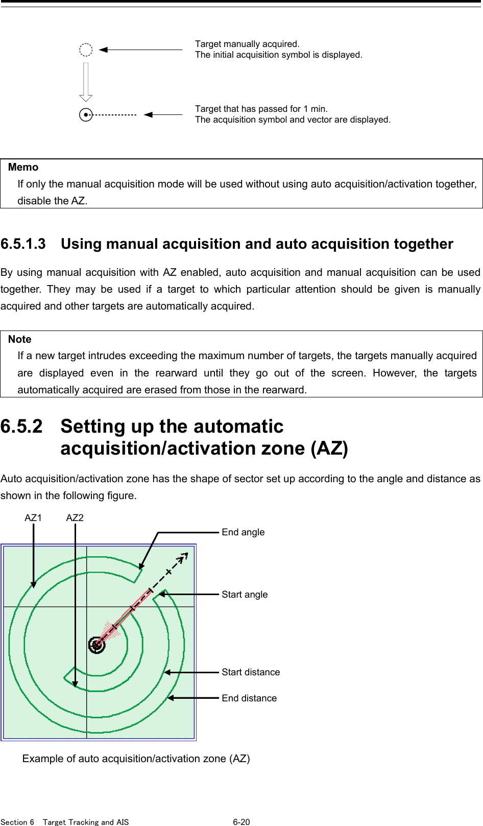
![6-21 Section 6 Target Tracking and AIS 1 2 3 4 5 6 7 8 9 10 11 12 13 14 15 16 17 18 19 20 21 22 23 24 25 26 27 Auto acquisition/activation zone (AZ) is set up using the following three methods. (1) Use the "New Target Warning" dialog in the [Alert] menu. (2) Use the cursor. (3) Use the EBL/VRM dial. 6.5.2.1 Using "New Target Warning" dialog box in the [Alert] menu 1 Click on the [Menu] button on the left toolbar. The menu is displayed. 2 Click [Alert] - [New Target Alarm] on the menu. The "New Target Alarm" dialog is displayed. 3 To set up AZ1, select the [Use AZ1] check box. To set up AZ2, select the [Use AZ2] check box. 4 To set up [Use AZ1], click on the [1] tab. To set up [Use AZ2], click on the [2] tab. Their respective setting items are displayed. 5 Enter the start angle, end angle, start distance and end distance of AZ. Start angle End angle Start distance End distance](https://usermanual.wiki/Japan-Radio/NKE2632.Instruction-Manual-Funtion-Part-1/User-Guide-2791060-Page-75.png)
![Section 6 Target Tracking and AIS 6-22 6.5.2.2 Using the cursor 1 Click on the [Menu] button on the left toolbar. The menu is displayed. 2 Click [Alert] - [New Target Alarm] on the menu. The "New Target Alarm" dialog is displayed. 3 Select AZ ([Use AZ1] or [Use AZ2]) to be set. 4 Click at the start angle position. The start angle is set. 5 Move the cursor and click at the end angle position. The line connecting the start angle and end angle appears. 6 Move the cursor and click at the start distance position. An arc appears at the start distance position. 7 Move the cursor and click at the end distance position. Auto acquisition/activation zone (AZ) with the shape of sector enclosed by start angle, end angle, start distance and end distance is created.](https://usermanual.wiki/Japan-Radio/NKE2632.Instruction-Manual-Funtion-Part-1/User-Guide-2791060-Page-76.png)
![6-23 Section 6 Target Tracking and AIS 1 2 3 4 5 6 7 8 9 10 11 12 13 14 15 16 17 18 19 20 21 22 23 24 25 26 27 6.5.2.3 Using the EBL/VRM dial for the setting 1 Click on the [Menu] button on the left toolbar. The menu is displayed. 2 Click [Alert] - [New Target Alarm] on the menu. The "New Target Alarm" dialog is displayed. 3 Select AZ ([Use AZ1] or [Use AZ2]) to be set. 4 Click on the [Make AZ1] button or [Make AZ2] button. The cursor enters the AZ creation mode. 5 Turn the EBL dial to set [Start Angle]. 6 Turn the VRM dial to set [Start Distance] 7 Press the EBL dial and the VRM dial. 8 Turn the EBL dial to set [End Angle]. Start angle Start distance](https://usermanual.wiki/Japan-Radio/NKE2632.Instruction-Manual-Funtion-Part-1/User-Guide-2791060-Page-77.png)
![Section 6 Target Tracking and AIS 6-24 9 Turn the VRM dial to set [End Distance]. 10 Press the EBL dial. 6.5.3 Tracked target information display Note When a target or own ship changes its course, or when a new target is acquired, its vector may not reach a given level of accuracy until 3 minutes or more has passed after such course change or target acquisition. Even if 3 minutes or more has passed, the vector may include an error depending upon the tracking conditions. 1 Set the cursor mode to the AUTO mode. 2 Click on the target of tracking whose numerical value is to be displayed. Numeric data for the specified target is displayed in the information monitoring window. Eng angle End distance](https://usermanual.wiki/Japan-Radio/NKE2632.Instruction-Manual-Funtion-Part-1/User-Guide-2791060-Page-78.png)
![6-25 Section 6 Target Tracking and AIS 1 2 3 4 5 6 7 8 9 10 11 12 13 14 15 16 17 18 19 20 21 22 23 24 25 26 27 The symbol display is changed to " ". The target data will remain on the radar display until the target is lost and its vector disappears, or until another target is designated. If a target with the mark " " is designated, only its true bearing and range appear until its vector appears. Cancellation of numeric data display 1 Set the cursor mode to the AUTO mode. 2 Place the cursor on the tracked target to cancel numeric value display and then click on. The numeric value disappears. Details on tracked target information Item Explanation TT ID ID No. of tracked target being displayed BRG True bearing Range Distance CTW (Course Through the Water stabilization mode)/ COG (Course Over the Ground stabilization mode) Course STW (Speed Through the Water stabilization mode) / SOG (Speed Over the Ground stabilization mode) Speed CPA Closest approach distance TCPA Time up to closest approach distance BCR Bow crossing distance BCT Bow crossing time 6.5.4 Erasing unwanted tracked targets If the vectors and symbols of the unwanted tracked targets remain displayed, the radar screen may become difficult to view. In such a case, unwanted tracked targets can be erased from the radar screen using the following method. To erase one target 1 Place the cursor on the tracked target to be cancelled and then right-click. The context menu is displayed. 2 Click on the [Cancel TT] on the context menu. The vector symbol of the tracked target disappears and only the radar image remains.](https://usermanual.wiki/Japan-Radio/NKE2632.Instruction-Manual-Funtion-Part-1/User-Guide-2791060-Page-79.png)
![Section 6 Target Tracking and AIS 6-26 To erase multiple targets 1 Place the cursor on the tracked target to be cancelled and then right-click. The context menu is displayed. 2 Click on the [Cancel TT mode] on the Context menu. The cursor changes to the selection cursor. 3 Place the cursor on another target to be cancelled and then click on. 4 Repeat the operation in step 3. The vector symbols of the clicked tracked targets disappear and only the radar image remains. To erase all targets 1 Place the cursor on the tracked target to be cancelled and then right-click. The context menu is displayed. 2 Click on the [Cancel all TT mode] on the Context menu. The vector symbols of all the tracked targets disappear and only the radar image remains. Note If all targets are cancelled, the tracking of all targets will stop; thus, automatic acquisition or manual acquisition must be performed newly. Unless necessary, do not cancel all targets. 6.5.5 Displaying Target ID No. A target ID number is a value displayed beside the acquisition symbol when a target is acquired. A target ID number 1 to 100 is automatically assigned to each target in acquisition order. Once a target ID number is assigned, it identifies the target until the target is lost or the target acquisition is canceled. Memo The ID number is always displayed for only targets with which numeric data is displayed. 1 Click on the [Menu] button on the left toolbar. The menu is displayed. 2 Click on [View] - [Options] - [Target]. The "Target" dialog is displayed.](https://usermanual.wiki/Japan-Radio/NKE2632.Instruction-Manual-Funtion-Part-1/User-Guide-2791060-Page-80.png)
![6-27 Section 6 Target Tracking and AIS 1 2 3 4 5 6 7 8 9 10 11 12 13 14 15 16 17 18 19 20 21 22 23 24 25 26 27 3 Select the method for displaying ID No. from the [TT Target ID] list. [On]: Displays target ID numbers. [Off]: Hides target ID numbers. [TT Track]: Displays ID numbers of only targets set for track of other ships. [Ship's Name]: When the ship’s name has been input in the “TT Target INFO” (property of tracked target) dialog box, that ship name is displayed. If the ship’s name has not been input, the identification number is displayed. Memo If there are many tracking targets and their symbol display is confusing, set Target Number Display to off to view the radar display easily. [TT Target ID] [TT Target ID] ECDIS screen RADAR screen](https://usermanual.wiki/Japan-Radio/NKE2632.Instruction-Manual-Funtion-Part-1/User-Guide-2791060-Page-81.png)
![Section 6 Target Tracking and AIS 6-28 6.5.6 Editing tracked target properties The tracked target property such as tracked target ID name can be arbitrarily edited for individual tracked targets acquired. The "TT Target INFO" dialog is used for editing. 6.5.6.1 Adding Tracked Target ID Name An ID name can be added to the tracked target acquired. 1 Right-click the cursor on the tracked target. The context menu is displayed. 2 Click on [Property] on the context menu. The "TT Target INFO" dialog box appears [Target ID] display [Name] input box [Edit Template] button Tracked target ID appears. Tracked target ID name is set. For the details, refer to "6.5.6.1 Adding Tracked Target ID Name". The track color of tracked target is set. For the details, refer to "6.5.6.2 Setting track color of tracked target". The target for which ground is fixed is set to a reference target. For the details, refer to "6.5.7 Setting target for which ground is fixed to a reference target" When a TT target and AIS target are determined to be the same targets, the TT target or AIS target to be displayed on a priority basis can be set. For the details, refer to "6.3.8 Association Target Symbols"](https://usermanual.wiki/Japan-Radio/NKE2632.Instruction-Manual-Funtion-Part-1/User-Guide-2791060-Page-82.png)
![6-29 Section 6 Target Tracking and AIS 1 2 3 4 5 6 7 8 9 10 11 12 13 14 15 16 17 18 19 20 21 22 23 24 25 26 27 3 Click on the [Name] input box or . The input method varies with the selected item. Input box : Enter a new name. When selected, the ship name ([Name]) entry window opens. Enter a ship name of up to 15 characters. : The names registered as templates are displayed in a list. Select a name from the list. To register ship names as templates 1 Click on the [Edit Template] button in the [TT Target INFO] dialog box. The [Edit Template] dialog box appears. 2 Enter the ship name to be registered as a template in the input text box. 3 Click on the [Register] button. The entered ship name is registered in the template list. 4 Repeat steps 2 and 3, and register necessary ship names. To cancel unwanted ship name registration 1 On the template list in the [Edit Template] dialog box, check the checkbox of the ship name whose registration to be canceled. 2 Click on the [Delete] button. The checked ship name is deleted from the template list. Input text box [Register] button Template list [Delete] button ](https://usermanual.wiki/Japan-Radio/NKE2632.Instruction-Manual-Funtion-Part-1/User-Guide-2791060-Page-83.png)
![Section 6 Target Tracking and AIS 6-30 6.5.6.2 Setting track color of tracked target The track color of tracked target is set. 1 Right-click on the cursor at the tracked target. 2 Click on the [Property] on the context menu. The "TT Target INFO" dialog box appears. 3 Select track color from the [Track Color] list. The selection items are as follows. Off, No.1-Color, No.2-Color, No.3-Color, No.4-Color, No.5-Color, No.6-Color, No.7-Color, No.8-Color, No.9-Color, No.10-Color, No.11 to 20-Color * In "Color," the track color name set by clicking [View] - [Options] - [Target Track] - [Plot] appears. For the details, refer to "16.2.8 Setting up the Display of Other Ship's Track"](https://usermanual.wiki/Japan-Radio/NKE2632.Instruction-Manual-Funtion-Part-1/User-Guide-2791060-Page-84.png)
![Section 6 Target Tracking and AIS 6-32 3 Click on [Property] in the context menu. The “TT Target INFO” dialog is opened. 4 To set the target to a reference target, check [Reference Target]. To not set the target to a reference target, uncheck [Reference Target]. 5 Select [TGT] from the COG/SOG source combo box in the own ship information at the top right corner of the screen. The ship speed is automatically calculated from the reference target and is displayed as the COG/SOG speed. When a reference target is set, the symbol display changes to “R ”. Note Only one target can be set as a reference target. When a new reference target is set, the previous reference target is cancelled. [Reference Target] check box](https://usermanual.wiki/Japan-Radio/NKE2632.Instruction-Manual-Funtion-Part-1/User-Guide-2791060-Page-86.png)
![6-33 Section 6 Target Tracking and AIS 1 2 3 4 5 6 7 8 9 10 11 12 13 14 15 16 17 18 19 20 21 22 23 24 25 26 27 6.5.8 Operation Test for Target Tracking Simulation is a function for determining if the target tracking function is working correctly or not. Accordingly, this function should be used only to check for the target tracking function operation. In particular, if this mode is used during navigation, a pseudo target will appear on the radar screen and cannot be easily identified from the real target. This may cause such an accident as collision. Do not use this mode during the navigation. The following operation test and checking are performed to check the operation of target tracking as required. The "TT Te st" dialog is used for operation. 1 Click on the [Menu] button on the left toolbar. The menu is displayed. 2 Click on the [Settings] - [TT Test] on the menu. The "TT Test" (Test for Target Tracking) dialog is displayed. A pseudo-target is generated on the radar screen to check that target tracking operates normally. For the details, refer to "6.5.8.2 Target tracking simulator (TT Simulator)". The gate size for acquiring and tracking targets are displayed. For the details, refer to "6.5.8.3 Gate display". The status of Target Tracking function is displayed. For the details, refer to "6.5.8.4 Status display". The operation of target detection circuit is checked. For the details, refer to "6.5.8.1 Test Video".](https://usermanual.wiki/Japan-Radio/NKE2632.Instruction-Manual-Funtion-Part-1/User-Guide-2791060-Page-87.png)
![Section 6 Target Tracking and AIS 6-34 6.5.8.1 Test Video Test Video is used to check whether the video signals under target acquisition and tracking are input to and processed in the target detection circuit normally. Normally, it is sufficient to just check that the VDIN of the Test Video is displayed. Note Test Video may not be displayed for a target which is not yet acquired or tracked. Test Video may not be displayed either if the [GAIN] dial or [SEA] dial is not properly adjusted. 1 Click on the [Menu] button on the left toolbar. The menu is displayed. 2 Click on the [Settings] - [TT Test] on the menu. The "TT Test" (Test for Target Tracking) dialog is displayed. 3 Select test video to be displayed from the [Test Video] combo box. The selected test video is displayed in the rearward of the radar image. If any target displayed clearly in the normal radar display is not displayed in the Test Video mode, the target detection circuit of the Target Tracking unit may have a trouble. To cancel test video 1 Select [Off] from the [Test Video] combo box. Test Video display turns off.](https://usermanual.wiki/Japan-Radio/NKE2632.Instruction-Manual-Funtion-Part-1/User-Guide-2791060-Page-88.png)
![6-35 Section 6 Target Tracking and AIS 1 2 3 4 5 6 7 8 9 10 11 12 13 14 15 16 17 18 19 20 21 22 23 24 25 26 27 6.5.8.2 [TT Simulator] (Target tracking simulator) Pseudo-targets are generated in certain known positions to check whether the target tracking units are operating normally. Since the pseudo-targets move depending on known parameters, the values for these pseudo-targets can be compared with the known value if the pseudo-targets are acquired and tracked, and displayed. Thus, it can be checked if the system is operating normally. 1 Click on the Standby/Transmit selector button for Radar system information to place the radar in the standby state. The button indication changes to [Standby]. 2 Click on the [Menu] button on the left toolbar. The menu is displayed. 3 Click on the [Settings] - [TT Test] on the menu. The "TT Test" (Test for Target Tracking) dialog is displayed. 4 Select simulator scenario from the [TT Simulator] combo box. Standby/Transmit selector button](https://usermanual.wiki/Japan-Radio/NKE2632.Instruction-Manual-Funtion-Part-1/User-Guide-2791060-Page-89.png)
![Section 6 Target Tracking and AIS 6-36 List of target tracking simulator/scenario Scenario Target No. Motion (true motion) Moving start point Speed [kn] Course [o] Range [NM] Bearing [o] Scenario1 1 28.3 45 9.5 270 2 22.4 27 1.12 333 3 15.3 293 9.25 45 Scenario2 1 30 135 8 23 2 20 270 5 135 Scenario3 1 45 180 5 23 2 0 - 3 340 3 30 0 8 180 Scenario4 1 0 0 2.02 31 2 70 225 7.01 37 Scenario5 1 20 45 4.47 288 2 30 45 5.1 304 3 40 45 6.71 288 4 0 - 7.07 307 5 60 200 12 352 6 20 225 11 315 7 40 190 14.4 349 8 - - 8 318 9 - - 9 318 10 - - 10 318 Scenario6 1 5 96 5 0 2 105 225 6 45 Note • When the simulator is operating, set 0° as the heading bearing 5 Click on the Standby/Transmit selector button to place the radar in the transmission state. The button indication changes to [Transmit]. The simulator turns on, the pseudo-target is generated, and the letter "X" appears on the lower side of the radar screen and near the pseudo-target to indicate that simulation mode is being executed. To cancel simulation 1 Click on the Standby/Transmit selector button to place the radar in the standby state. The button indication changes to [Standby] to enter transmission preparation state. 2 Select [Off] from the [TT Simulator] combo box in the "TT Test" dialog. TT Simulator display turns off.](https://usermanual.wiki/Japan-Radio/NKE2632.Instruction-Manual-Funtion-Part-1/User-Guide-2791060-Page-90.png)
![6-37 Section 6 Target Tracking and AIS 1 2 3 4 5 6 7 8 9 10 11 12 13 14 15 16 17 18 19 20 21 22 23 24 25 26 27 6.5.8.3 [Gate Display] The gate displays an area monitoring a target using the TT function. This equipment allows the gate size to change automatically according to target range and size. The gate size can be checked using the following function. 1 Click on the [Menu] button on the left toolbar. The menu is displayed. 2 Click on the [Settings] - [TT Test] on the menu. The "TT Test" (Test for Target Tracking) dialog is displayed. 3 Select the [Gate Display] checkbox. When [Gate Display] is selected, the gate is displayed. When [Gate Display] is cleared, the gate is not displayed. 4 Set the cursor mode to the AUTO mode.](https://usermanual.wiki/Japan-Radio/NKE2632.Instruction-Manual-Funtion-Part-1/User-Guide-2791060-Page-91.png)
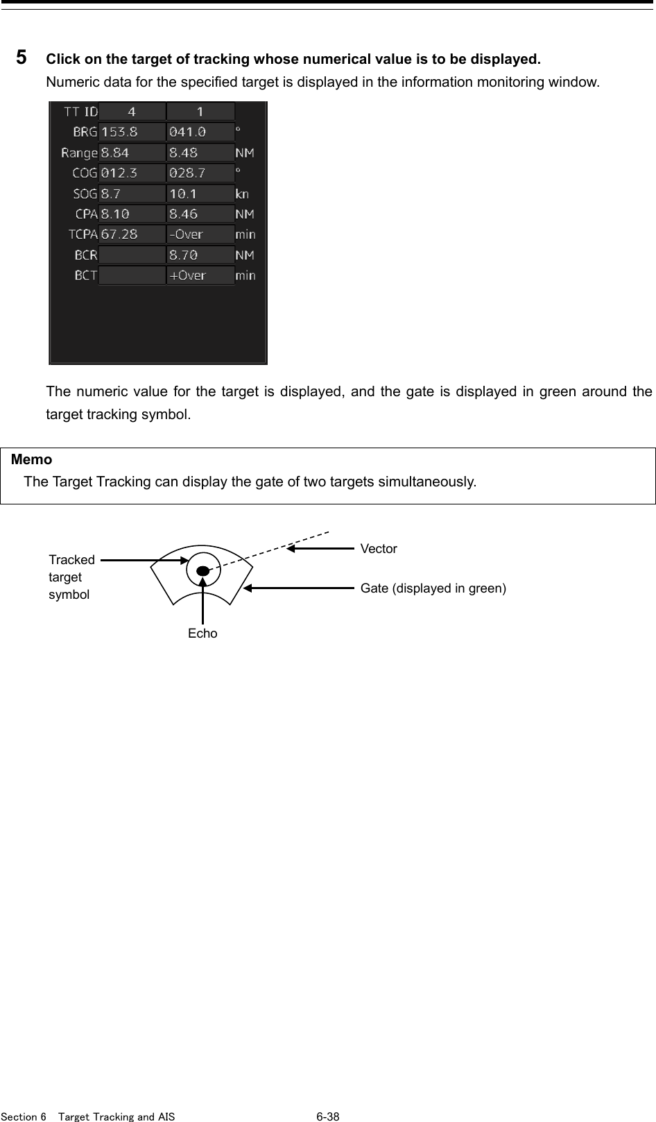
![6-39 Section 6 Target Tracking and AIS 1 2 3 4 5 6 7 8 9 10 11 12 13 14 15 16 17 18 19 20 21 22 23 24 25 26 27 6.5.8.4 Status display The status of the TT function is displayed. 1 Click on the [Menu] button on the left toolbar. The menu is displayed. 2 Click on the [Settings] - [TT/AIS] - [TT Test] on the menu. The "TT Test" (Test for Target Tracking) dialog is displayed. 3 Check the display of [Status]. [Vector Constant] : Vector response [VD Level Mode (Manual)] : Using quantization level on manual acquisition [VD Level (Manual)] : Quantization level on manual acquisition [Video Level (Auto)] : Quantization level on automatic acquisition [Gate Size] : Size of gate used for tracking [Tracking] : Number of targets currently acquired](https://usermanual.wiki/Japan-Radio/NKE2632.Instruction-Manual-Funtion-Part-1/User-Guide-2791060-Page-93.png)
![Section 6 Target Tracking and AIS 6-40 6.6 Setting and Operating AIS 6.6.1 Enabling AIS Function Note • When the AIS function is set to Off, the AIS display function is turned off and AIS symbols are no longer displayed. • Once AIS function is set to Off, even If a dangerous target exists, the function is not automatically switched to On. 1 Click on the [AIS] button for other ship information on the upper right of PPI. The button indication becomes ON and the AIS function becomes enabled. ON indication: The received AIS information is displayed on the screen. 6.6.2 Activating AIS targets (Activate AIS) Activates an AIS target, and displays the target's vector and make a collision decision. 6.6.2.1 Manual activation Activates an AIS target in manual mode to display the vector and heading line. 1 Set the cursor mode to the AUTO mode. 2 Place the cursor on the sleeping AIS symbol to be activated and then click on. The selected AIS target is activated.](https://usermanual.wiki/Japan-Radio/NKE2632.Instruction-Manual-Funtion-Part-1/User-Guide-2791060-Page-94.png)
![6-41 Section 6 Target Tracking and AIS 1 2 3 4 5 6 7 8 9 10 11 12 13 14 15 16 17 18 19 20 21 22 23 24 25 26 27 6.6.2.2 Automatic activation Activate an AIS target in automatic mode to display the vector and heading line. When the automatic activation function is used, AIS targets are automatically activated when they go into the automatic activation zone. The automatic activation zone is identical to the automatic acquisition zone (AZ) used for target tracking. For the zone setting, refer to "6.5.1.1 Automatic acquisition ". Note When the AIS target's symbol is activated but the vector is not displayed, the following are probable causes of the trouble: • COG/SOG is not input yet from the GPS. • The selected speed sensor is malfunctioning. Memo The bearing or range in the acquisition/activation zone shall be based on the position of the radar antenna. If there are more AIS targets than the allowable maximum, they are deactivated from the low-priority (Refer to "6.3 Displaying Symbols"). 6.6.3 Deactivating AIS targets Deactivates an AIS target and clear the display of the vector and heading line. [Deactivating one AIS target] 1 Right-click on the AIS target to be deactivated. The setting items for cursor modes are displayed. 2 Click on the [Deactivate] on the Context menu. The selected AIS target is deactivated. [Deactivating multiple AIS targets] 1 Right-click on the AIS target. The setting items for cursor modes are displayed. 2 Click on the [Deactivate mode] on the Context menu. The cursor changes to the selection cursor. 3 Click on the AIS target to be deactivated. The selected AIS target is deactivated. Note This operation is available only for an activated AIS target.](https://usermanual.wiki/Japan-Radio/NKE2632.Instruction-Manual-Funtion-Part-1/User-Guide-2791060-Page-95.png)
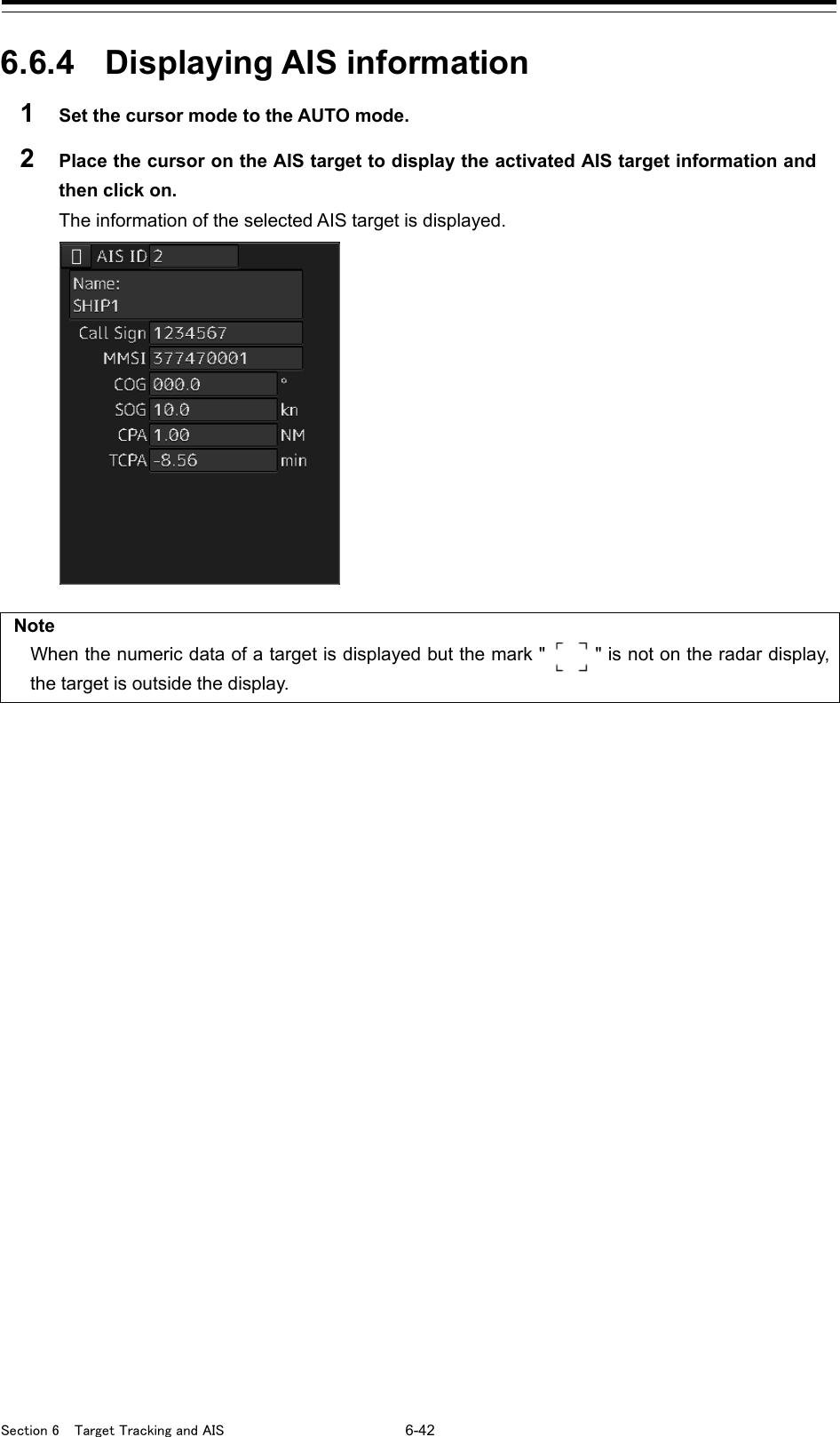
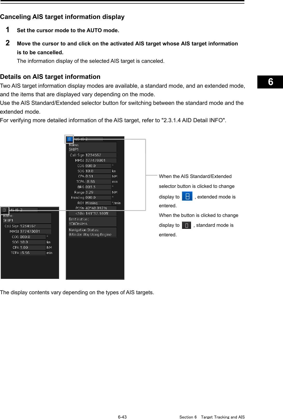
![Section 6 Target Tracking and AIS 6-44 [Normal AIS target] Item Explanation AIS ID ID No. of AIS target Name Ship name of AIS target Call Sign Call sign of AIS target MMSI Maritime Mobile Service Identity COG or CTW COG: Course Over the Ground CTW: Course Through Water * In ground mode, COG is displayed. In water mode, CTW is displayed. * Operates in fixed ground mode on the ECDIS screen. SOG or STW SOG: Speed Over the Ground STW: Speed Through Water *If the SOG or STW column is Over, the speed of other system is 102.2 kn or more. * In extended mode, the display area for two simple modes is used. * Operates in fixed ground mode on the ECDIS screen. CPA Closest approach distance TCPA Time up to closest approach distance BRG True direction * In standard mode, this item is not displayed. Range Distance * In standard mode, this item is not displayed. Heading Heading * In standard mode, this item is not displayed.](https://usermanual.wiki/Japan-Radio/NKE2632.Instruction-Manual-Funtion-Part-1/User-Guide-2791060-Page-98.png)
![Section 6 Target Tracking and AIS 6-46 [AIS SARTTarget] There is neither the Call Sign nor Destination item. The display of some items of Navigation Status is different. Otherwise, the display contents are the same as those of usual AIS target. Navigation Status Display 0 ~ 13: Same display as for the usual ship 14: AIS-SART ACTIVE(14) 15: AIS-SART TEST(15) Memo Switching between standard and extended modes is not provided.](https://usermanual.wiki/Japan-Radio/NKE2632.Instruction-Manual-Funtion-Part-1/User-Guide-2791060-Page-100.png)
![6-47 Section 6 Target Tracking and AIS 1 2 3 4 5 6 7 8 9 10 11 12 13 14 15 16 17 18 19 20 21 22 23 24 25 26 27 [AIS AtoN Target] Item Description AIS ID AIS target ID Name Ship name of AIS target MMSI Maritime Mobile Service Identity code BRG True bearing Range Range POSN Latitude/longitude >10m or <10m >10m:Position fixing accuracy low <10m:Position fixing accuracy high Type Displays the AtoN type. Fort he details, refer to the “Type” table. * Not displayed in standard mode. Virtual Flag Real AtoN: Real AtoN Virtual AtoN:Virtual AtoN (does not exist) * Not displayed in standard mode. Assigned Mode Autonomous and continuous:Operating in autonomous/continuous mode Assigned:Operating in assignment mode * Not displayed in standard mode. EPFS Displays the EPFS type. For the details, refer to the “EPFS” table. * Not displayed in standard mode.](https://usermanual.wiki/Japan-Radio/NKE2632.Instruction-Manual-Funtion-Part-1/User-Guide-2791060-Page-101.png)
![Section 6 Target Tracking and AIS 6-50 6.6.5 Displaying Target ID No. When an AIS target is activated, a target ID number is displayed next to the AIS target symbol. A target ID number 1 to 1000 is assigned to each target in the order of receiving targets by MFD. Once a target ID number is assigned, it identifies the AIS target until the AIS target is lost. 1 Click on the [Menu] button on the left toolbar. The menu is displayed. 2 Click on the [View] - [Options] - [Target] on the menu. The "Target" dialog is displayed. 3 Select the method for displaying ID No. from the [AIS Target ID] combo box. [On] : Displays target ID numbers. [Off] : Hides target ID numbers. [AIS Track] : Displays ID numbers of only targets set for track of other ships. [Ship's Name] : Displays the ship's name. Memo - ID number or ship's name is always displayed for only targets with which numeric value is displayed. - If there are many AIS targets and their symbol display is confusing, set Target Number Display to off to view the radar display easily. [AIS Target ID]](https://usermanual.wiki/Japan-Radio/NKE2632.Instruction-Manual-Funtion-Part-1/User-Guide-2791060-Page-104.png)
![6-51 Section 6 Target Tracking and AIS 1 2 3 4 5 6 7 8 9 10 11 12 13 14 15 16 17 18 19 20 21 22 23 24 25 26 27 6.6.6 Checking and setting AIS target property The AIS target property such as ID name can be checked for individual acquired AIS targets. The track color of AIS target can also be set. The "AIS Target INFO" dialog is used for editing. 6.6.6.1 Setting track color of AIS target The track color of AIS target is set. 1 Right-click on the AIS target. The context menu is displayed. 2 Click on [Property] on the context menu. The "AIS Target INFO" dialog box appears. AIS target ID appears. AIS target ID name appears. The track color of AIS target is set. For the details, refer to "6.6.6.1 Setting track color of AIS target". When a TT target and AIS target are determined to be the same targets, the TT target or AIS target to be displayed on a priority basis can be set. For the details, refer to "6.3.8 Association Target Symbols".](https://usermanual.wiki/Japan-Radio/NKE2632.Instruction-Manual-Funtion-Part-1/User-Guide-2791060-Page-105.png)
![Section 6 Target Tracking and AIS 6-52 3 Select the track color from the [Track No.] combo box. The selection items are as follows. Off, No.1-Color, No.2-Color, No.3-Color, No.4-Color, No.5-Color, No.6-Color, No.7-Color, No.8-Color, No.9-Color, No.10-Color, No.11 to 20-Color * In "Color," the track color name set by clicking [View] - [Options] - [Target Track] - [Plot] is displayed. For the details, refer to "16.2.8 Setting up the Display of Other Ship's Track". 6.6.7 Conditions for deciding AIS target to be lost About an AIS target lost When the data of a target cannot be received for a specified time, the target is decided to be lost and the target data is deleted. As shown in the table below, the time until target data is deleted varies depending on the class of received data and the target status. Note • Since the lost time and that of the AIS indicator are different, this equipment may display lost information earlier than the AIS display depending on the target status (speed, navigation status, etc.). • The target of lost target is continuously displayed until Lost Warning is approved. Since negligence of approval operation may hinder display of a new AIS target, perform approval operation as soon as possible. Conditions for Deciding Target to be Lost Targ et status Time until data is lost SOLAS ship (Class A) Non-SOLAS ship (Class B) Vessel below 3 kn (Class A) or 2 kn (Class B) and it is now at anchor or on the berth 18 min 18 min Vessel of 3 kn or more and it is now at anchor or on the berth 60 sec — Vessel of 0 to 14 kn (Class B: 2 to 14 knots) 60 sec 180 sec Vessel of 0 to 14 kn and it is now changing the course (Class B: 2 to 14 knots) 60 sec 180 sec Vessel of 14 to 23 knots 36 sec 180 sec Vessel of 14 to 23 kn and it is now changing the course 36 sec 180 sec Vessel of 23 kn or more 30 sec 180 sec Vessel of 23 kn or more and it is now changing the course 30 sec 180 sec AtoN (Aids to navigation) 18 min SART 6 min 6 min AIS-AtoN 18 min 18 min AIS SAR aircraft 60 sec AIS coastal base station 60 sec](https://usermanual.wiki/Japan-Radio/NKE2632.Instruction-Manual-Funtion-Part-1/User-Guide-2791060-Page-106.png)
![6-53 Section 6 Target Tracking and AIS 1 2 3 4 5 6 7 8 9 10 11 12 13 14 15 16 17 18 19 20 21 22 23 24 25 26 27 Note • When a dangerous target ship is lost, a lost alarm is issued and the symbol changes to a lost symbol. The system calculates the current position from the last-received data and continues displaying the symbol for eternity. • When the [AIS] button in the target ship information window is turned off, the symbol is canceled. 6.7 Alert Display Target tracking and AIS system have the following alerts. Message Description AIS ACT 95% Capacity The number of activated AIS targets reached 95% of tolerance. AIS 95% Capacity The number of AIS targets reached 95% of tolerance. CPA/TCPA(AIS) CPA/TCPA warning (AIS) Lost(AIS) The AIS target was lost. AIS MAX Target The number of AIS targets reached the maximum number of targets displayed. New Target(AIS) The AIS target was acquired and activated. Not Allowed(TT Out of Range) Out of TT acquisition range Trial Under the trial process. Occurs instead of a danger target alarm when the predicted route of the tracking target intersects with the CPA/TCPA limit range TT(95% Capacity) The number of TT targets reached 95% of tolerance. TT(CPA/TCPA) CPA/TCPA warning (TT) TT(Lost) Acquired TT was lost. TT(MAX Target) The number of TT targets reached the maximum number of targets. TT(New Target) TT was acquired. TT(Out of Range ) TT went out of 32NM. TT(Reference Lost) The TT reference target was lost.](https://usermanual.wiki/Japan-Radio/NKE2632.Instruction-Manual-Funtion-Part-1/User-Guide-2791060-Page-107.png)
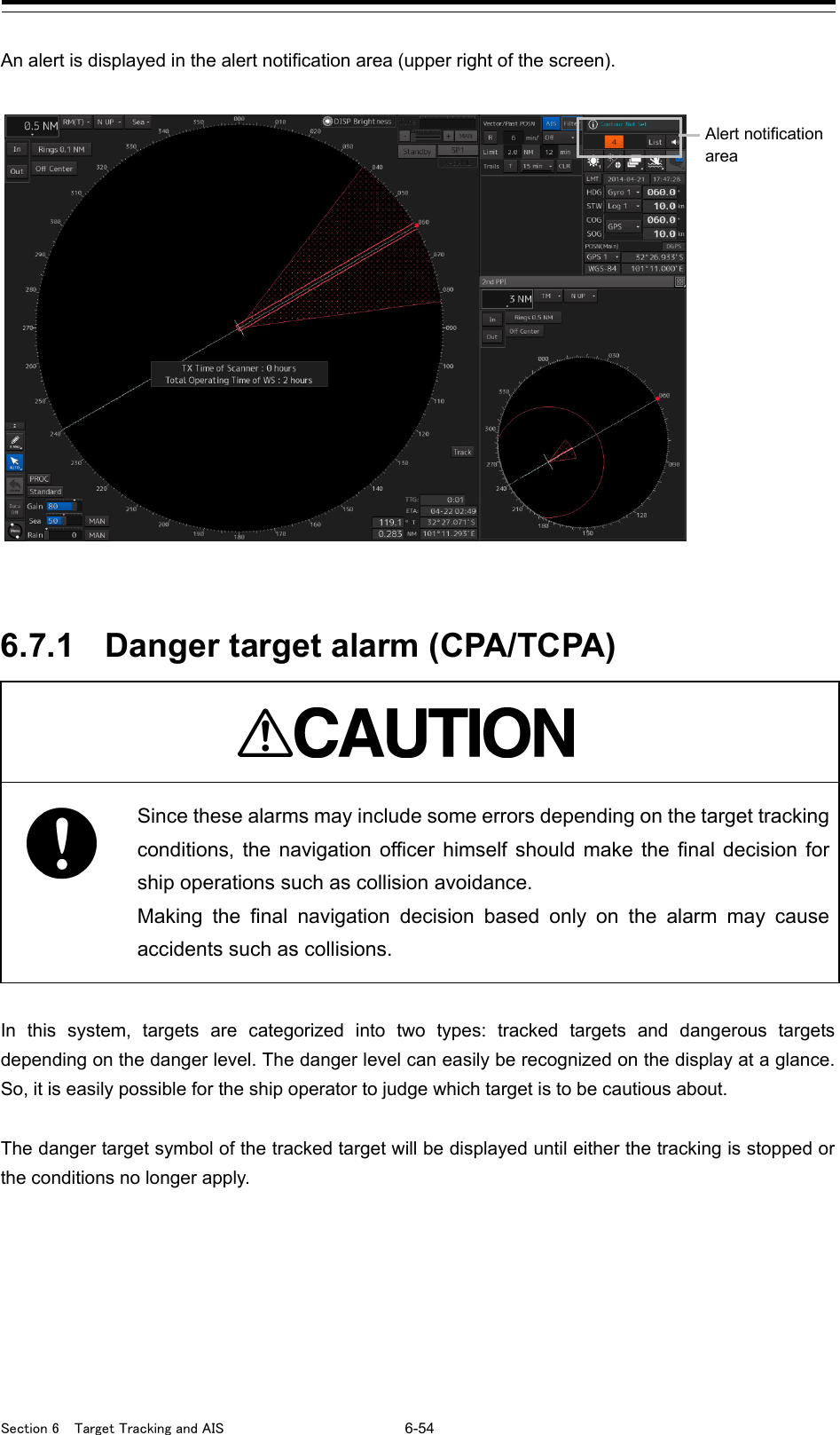
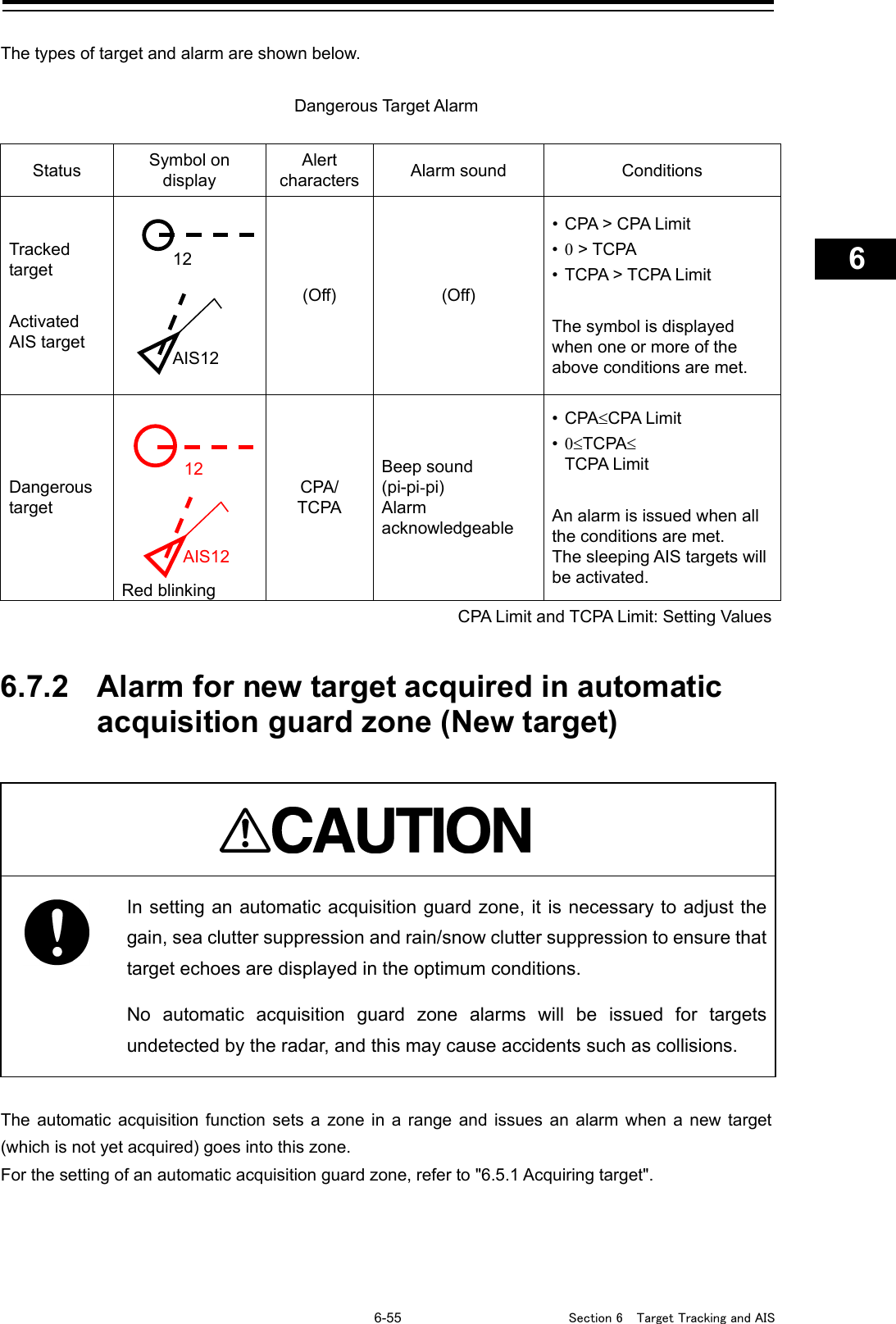
![Section 6 Target Tracking and AIS 6-56 Alarm for New Target Acquired in Automatic Acquisition Guard Zone Status Symbol on display Alert characters Alarm sound Conditions New target in automatic acquisition guard zone Red Blinking New Target Beep sound (pipi) Alarm acknowledgeable The alarm is issued when a new target is acquired in the automatic acquisition guard zone. Note When an already acquired target goes into automatic acquisition guard zone, the alarm for the new target acquired in automatic acquisition guard zone does not sound. 6.7.3 Lost target notification (Lost) Note If the gain, sea clutter suppression, rain/snow clutter suppression are not adjusted adequately, the lost target notification may be easily generated. So, such adjustments should be very carefully. When it is impossible to continue tracking any acquired and tracked target, or the data of AIS target cannot received for a specified time, the [Lost] notification will be issued. The typical causes for alarm are shown below: - The target echo is very weak. - The target is hidden by a shore or a large ship and its echo is not received. - The target echo is blurred by sea clutter or rain/snow clutter. If a target under tracking goes into a range over 32 NM and can no longer be tracked, it is canceled without a lost target notification being issued. Lost Target Notification Status Symbol on display Alert characters Alarm sound Conditions Lost target Red Blinking Lost Beep sound (pipi) notification acknowledgeable The notification will sound once when a lost target symbol is displayed. AIS12 12 12](https://usermanual.wiki/Japan-Radio/NKE2632.Instruction-Manual-Funtion-Part-1/User-Guide-2791060-Page-110.png)
![6-57 Section 6 Target Tracking and AIS 1 2 3 4 5 6 7 8 9 10 11 12 13 14 15 16 17 18 19 20 21 22 23 24 25 26 27 6.7.4 Target Tracking function alarm (TT Data) If some failure occurs in input signals or the processor circuits, an alarm will be issued. If an alarm is issued in the Target Tracking function, [TT(Data)] is displayed in the alarm indication and nothing is displayed in the indication of the target tracking information. Its cause is inferred that the Target Tracking function is malfunctioned. In that case, please consult with our branch office, branch shop, sales office, or our distributor in your district to repair it. Target Tracking function Alarm Alert characters Alarm sound Condition TT (Data) Beep sound (pipi) If the Target Tracking function has some abnormal condition, this alarm issues. 6.7.5 Gyro set notification (Set Gyro) The GYRO I/F in this system receives signals from a gyro. Even if the power is turned off, the system will follow up the gyro. However, the system stops the follow-up operation when the power of the master gyro is turned off or when any trouble occurs to the line. When the power of the master gyro is recovered, the [Set Gyro] notification will be issued. When this notification is issued, set the true bearing value of the gyro. For the details, refer to “5.4.13 True bearing”. Gyro Set Notification Alert characters Alarm sound Conditions Set Gyro Beep sound (pi-) The signals from the gyro are stopped, but the gyro is recovered.](https://usermanual.wiki/Japan-Radio/NKE2632.Instruction-Manual-Funtion-Part-1/User-Guide-2791060-Page-111.png)
![Section 6 Target Tracking and AIS 6-58 6.8 Track Function 6.8.1 Setting the Past position 1 Select the track display interval time from the past position interval selector combo box for other ship information at the upper right of PPI. The past position is set. [Off] : Tracks are not displayed. [Numeric] : Tracks are displayed at intervals of the specified value. The past position function can display up to ten past positions of a target under tracking. The past position display interval can be set to specified time intervals of 0.5, 1, 2, or 4 minutes, or specified range intervals of 0.1, 0.2, 0.5, or 1 NM. When [Off] is displayed, the track display function is turned off. The track mode operates in conjunction with the vector mode, and a true or relative track is displayed. In relative vector mode, the relative tracks of the target are displayed. In true vector mode, true tracks that are calculated from the relative bearing, range, own ship's course, and speed are displayed. Note When the target is acquired, past position of traced target is start plot. When the AIS target is displayed, past position of AIS target is start plot. If the past position plotted time or range is short, the indicated past position duration may not have achieved the specified time or range. 6.8.2 Setting the other ship's tracks This function makes settings for the tracks of tracked targets and AIS targets. This equipment can display the tracks of up to 20 target ships.](https://usermanual.wiki/Japan-Radio/NKE2632.Instruction-Manual-Funtion-Part-1/User-Guide-2791060-Page-112.png)
![6-61 Section 6 Target Tracking and AIS 1 2 3 4 5 6 7 8 9 10 11 12 13 14 15 16 17 18 19 20 21 22 23 24 25 26 27 6.9 Entering Own Ship's AIS Voyage Data Set the own ship's AIS voyage data. 1 Click on the [Menu] button on the left toolbar. The menu is displayed. 2 Click on [TT/AIS] - [AIS Voyage Data] on the menu. The "AIS Voyage Data" dialog box appears. In the "AIS Voyage Data" dialog box, information collected from AIS is displayed. 3 Enter information manually if not being displayed, or change the information being displayed. Item Setting Destination Enter the destination in the [Destination] input box (maximum 20 characters), or display the history list and click on the destination to enter. ETA (UTC) Click on the calendar icon to display the date picker, and enter the expected date (and time) of arrival by clicking. NAV Status Select the "Navigation Status" from the combo box. For the details of Navigation Status, refer to "6.6.4 Displaying AIS information". Draft Enter the draft in the [Draft] input box in the range between 0 and 25.5 m. The draft can be entered in increments of 0.1 m. If the draft is more than 25.5 m, enter 25.5 m. Cargo category Select the cargo category from the combo box. Persons on-board Enter the number of persons on board in the [Persons on-board] input box in the range between 0 and 8191. If the number of persons on board is more than 8191 persons, enter 8191. 4 Click on the [OK] button to save the input information.](https://usermanual.wiki/Japan-Radio/NKE2632.Instruction-Manual-Funtion-Part-1/User-Guide-2791060-Page-115.png)
![Section 6 Target Tracking and AIS 6-62 6.10 Editing and Sending AIS Messages AIS messages can be edited and sent. 1 Click on the [Menu] button on the left toolbar. The menu is displayed. 2 Click on [TT/AIS] - [Edit and Send AIS Message] on the menu. The "Edit and Send AIS Message" dialog box appears. 3 Specify whether a message will be sent by specifying an MMSI code or distributing a broadcast message. For the details, refer to "To send a message by specifying an MMSI code:" and "To distribute a broadcast message:". 4 Display the [Message Category] list and select the type of the message to send. To send a safety related message: Click on [Safety Message]. To send a routine message: Click on [Routine Message]. 5 Type a message in the message input area. To automatically enter own ship's latitude/longitude/UTC: Click on the [LL&Time] (latitude/longitude/time) button. To copy an existing message: Click on the [View Tray] button to display the contents of the AIS Message Tray. Select the message to copy to display it, and then copy it. The message can be copied from the beginning up to the maximum number of characters. Message input area](https://usermanual.wiki/Japan-Radio/NKE2632.Instruction-Manual-Funtion-Part-1/User-Guide-2791060-Page-116.png)
![6-63 Section 6 Target Tracking and AIS 1 2 3 4 5 6 7 8 9 10 11 12 13 14 15 16 17 18 19 20 21 22 23 24 25 26 27 Note The maximum number of characters that can be input changes depending on the transmission method and the message type. • Sending a message by specifying the MMSI code - Safety message: Up to 156 characters - Routine message: Up to 151 characters • Distributing a broadcast message - Safety message: Up to 161 characters - Routine message: Up to 156 characters 6 Click on the [Send] button to send the message. The message transmission confirmation dialog box appears. When sending a message by specifying an MMSI code: When distributing a broadcast message: 7 Click on the [OK] button to send the message. To cancel the transmission of the message, click on the [Cancel] button. The following dialog box appears while sending a message. The transmission of the message currently in progress can be stopped by clicking the [Cancel] button.](https://usermanual.wiki/Japan-Radio/NKE2632.Instruction-Manual-Funtion-Part-1/User-Guide-2791060-Page-117.png)
![Section 6 Target Tracking and AIS 6-64 The following dialog box appears when the transmission of a message completes. 8 Click on the [OK] button to close the dialog box. 9 To save an MMSI code and a typed message in the case of MMSI transmission, click on the [Save] button. 10 Click on the [x] button to close the dialog box. To send a message by specifying an MMSI code: 1 Click on the [Addressed MMSI] (specified MMSI code) button. 2 Type an MMSI code (9 digits) in the [MMSI] input box. The name of the ship having the entered MMSI code is displayed in the [Name] box. The identification number is displayed in the [Target ID] box. 3 Type a message in the message input area. In the case of a safety related message: Maximum 156 characters In the case of a routine message: Maximum 151 characters To distribute a broadcast message: 1 Click on the [Broadcast] button. 2 Type a message in the message input area. In the case of a safety related message: Maximum 161 characters In the case of a routine message: Maximum 156 characters](https://usermanual.wiki/Japan-Radio/NKE2632.Instruction-Manual-Funtion-Part-1/User-Guide-2791060-Page-118.png)
![6-65 Section 6 Target Tracking and AIS 1 2 3 4 5 6 7 8 9 10 11 12 13 14 15 16 17 18 19 20 21 22 23 24 25 26 27 6.11 AIS Message Tray The received, sent and saved AIS messages are displayed in AIS Message Tray in a list form. Memo The information reference window such as AIS message tray can be switched to standard window display or extended window display. In this example, extended window display is used. For the details of switching between standard window display and extended window display, refer to "2.3.2.1 Switching between a standard window and an extended window". 6.11.1 Displaying the AIS message tray 1 Click on the [Menu] button on the left toolbar. The menu is displayed. 2 Click on [TT/AIS] - [AIS Message Tray] on the menu. The "Information Reference" window appears. 3 Click on the [AIS MSG Tray] button. The AIS Message Tray is displayed. Memo The AIS message tray can also be displayed by clicking on the [View Tray] button in the "Edit and Send AIS Message" dialog.](https://usermanual.wiki/Japan-Radio/NKE2632.Instruction-Manual-Funtion-Part-1/User-Guide-2791060-Page-119.png)
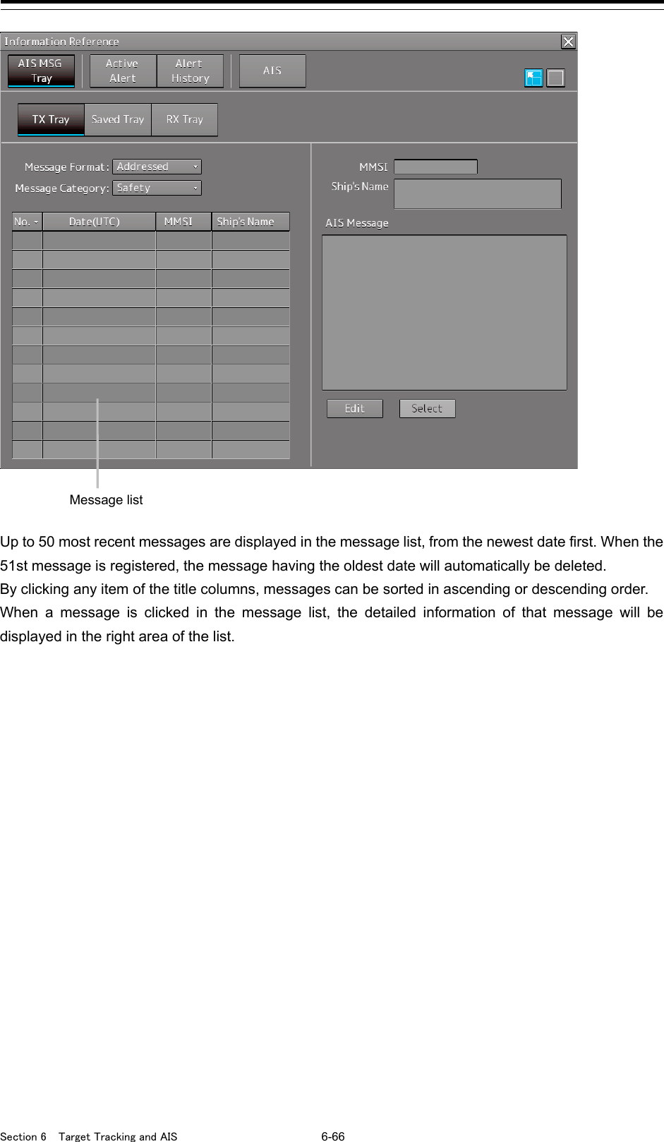
![6-67 Section 6 Target Tracking and AIS 1 2 3 4 5 6 7 8 9 10 11 12 13 14 15 16 17 18 19 20 21 22 23 24 25 26 27 6.11.2 Switching message display To display transmitted messages: Click on the [TX Tray] (Transmitted Tray) button. To display saved messages: Click on the [Saved Tray] button. To display received messages: Click on the [RX Tray] (Received Tray) button. Unread messages are displayed in boldface. To filter messages by specifying the transmission method: To display only messages sent/received by specifying an MMSI code: Click on the [Addressed] (address specification) button. To display only messages distributed through broadcasting: Click on the [Broadcast] button. When messages are not filtered by the transmission method: Click on the [All] (display all) button. To filter messages by specifying category: To display only safety related messages: Click on the [Safety] (safety related) button. To display only routine messages: Click on the [Routine] button. When messages are not filtered by category: Click on the [All] (display all) button.](https://usermanual.wiki/Japan-Radio/NKE2632.Instruction-Manual-Funtion-Part-1/User-Guide-2791060-Page-121.png)
![Section 6 Target Tracking and AIS 6-68 6.11.3 Sending a message in the message tray after editing 1 Click the message to copy in the message list. 2 Click on the [Edit] or [Select] button. When the AIS Message Tray is displayed by opening the AIS Message Tray submenu: Click the [Edit] button. The [Edit and Send AIS Message] dialog box appears, and the AIS message will be copied to the [Edit and Send AIS Message] dialog box. When a message is sent by specifying an MMSI code, the MMSI code will also be copied: When the AIS Message Tray was displayed by clicking the [View Tray] button in the [Edit and Send AIS Message] dialog box: Click the [Select] button. The AIS message will be copied to the [Edit and Send AIS Message] dialog box. The MMSI code is not copied by this method.](https://usermanual.wiki/Japan-Radio/NKE2632.Instruction-Manual-Funtion-Part-1/User-Guide-2791060-Page-122.png)
![6-69 Section 6 Target Tracking and AIS 1 2 3 4 5 6 7 8 9 10 11 12 13 14 15 16 17 18 19 20 21 22 23 24 25 26 27 6.12 Highlighting TT/AIS Symbols TT/AIS symbols can be searched by specifying criteria and highlight them. 1 Click on the [Menu] button on the left toolbar. The menu is displayed. 2 Click on [TT/AIS] - [Highlighting] on the menu. The "Highlighting" dialog box appears. 3 To include all search criterions as highlight targets, select the [Highlighting by the following search criteria] checkbox. To exclude all search criterions from highlight targets, clear the [Highlighting by the following search criteria] checkbox. 4 If the [Highlighting by the following search criteria] checkbox is selected in step 3 above, clear the checkboxes of the search criterion to be excluded from highlighting. MMSI MID Code input box Registry of ship display [TT/AIS] tab [AIS] tab](https://usermanual.wiki/Japan-Radio/NKE2632.Instruction-Manual-Funtion-Part-1/User-Guide-2791060-Page-123.png)
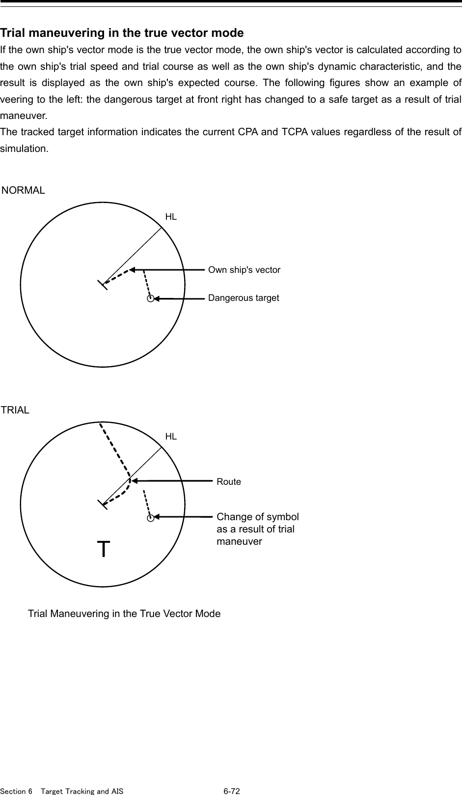
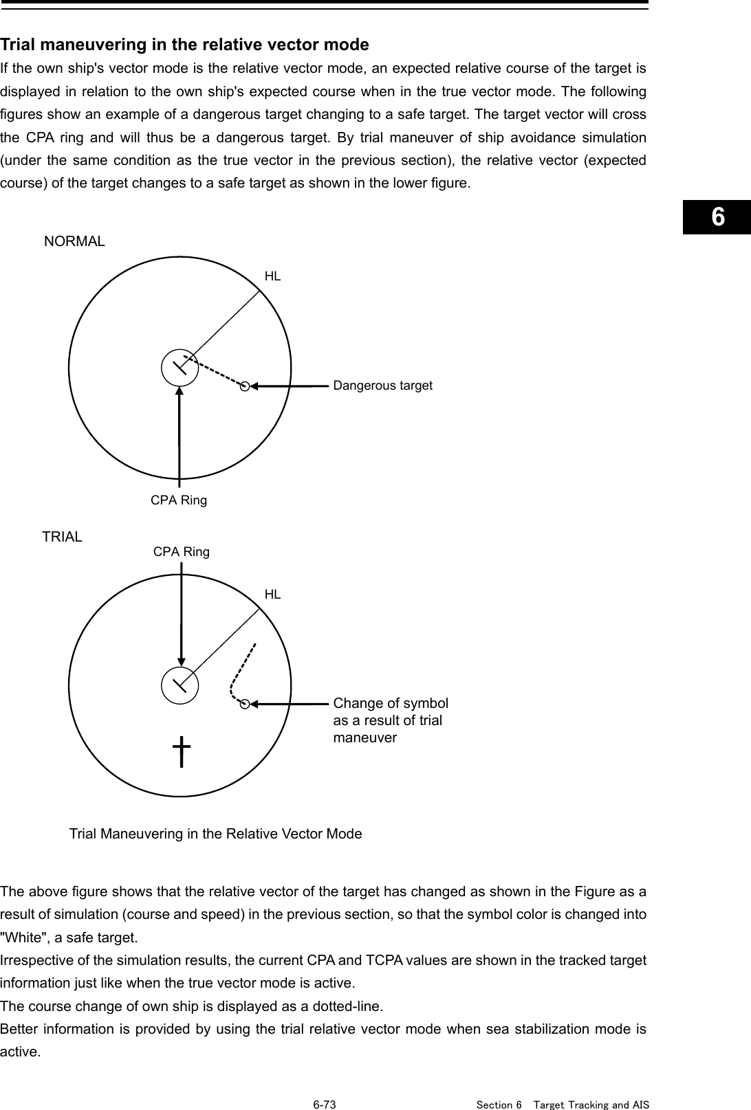
![Section 6 Target Tracking and AIS 6-74 6.13.2 Performing a trial maneuver 1 Click on the [Menu] button on the left toolbar. The menu is displayed. 2 Click on [TT/AIS] - [Trial Maneuver] on the menu. The "Trial Maneuver" dialog box appears. 3 Select the [Trial Function] checkbox. The trial function is turned on. When Trial Function is set to On, the character "T" blinks at the bottom of the own ship display field in the radar display and means a trial maneuver. 4 Enter a setting value in each of the [Course] and [Speed] input boxes. Memo [Course] can be set up by turning the [EBL] dial and [Speed] by turning the [VRM] dial. 5 Set other characteristics. [Vector Time]: Vector time (1 to 120 min) [Time to Maneuver]: Time until trial maneuvering is started (0 to 30 min) [Own Ship's Dynamic Trait]: When this item is clicked, the dialog is displayed to set own ship's dynamic trait. For the details, refer to "18.8 Setting own ship's dynamic trait". For the settings of [Own Ship's Dynamic Trait], refer to "18.5.2 Setting own ship's dynamic trait". The dangerous target symbol is displayed in red and the safe target symbol is displayed in white. The color of the safe target symbol can be changed with [Target Symbol] of [Settings] - [General] - [Color and Brightness]. For the details, refer to "18.18 Setting Colors and Brightness". Time countdown display](https://usermanual.wiki/Japan-Radio/NKE2632.Instruction-Manual-Funtion-Part-1/User-Guide-2791060-Page-128.png)
![6-75 Section 6 Target Tracking and AIS 1 2 3 4 5 6 7 8 9 10 11 12 13 14 15 16 17 18 19 20 21 22 23 24 25 26 27 Vector Time is valid only when Trial Function is set to On. If it is Off, the vector time before trial maneuvering is displayed. Time until the start of trial maneuvering is counted down directly after the input. The acceleration and deceleration are influenced depending on the relationship between the current speed and the input speed for trial maneuvering. If 0.0 kn/min is set for [Acceleration] when the speed for trial maneuvering is faster than the current speed, or for [Deceleration] when the speed for trial maneuvering is slower than the current speed, the system performs simulation on the assumption that the speed is changed directly after the time set for [Time to Maneuver]. To finish trial operation: 1 Clear the [Trial Function] checkbox.](https://usermanual.wiki/Japan-Radio/NKE2632.Instruction-Manual-Funtion-Part-1/User-Guide-2791060-Page-129.png)
![Section 6 Target Tracking and AIS 6-76 6.14 Displaying the TT/AIS Target List The information of targets being monitored with the TT and AIS functions can be displayed in a list on the information monitoring window. 6.14.1 Displaying TT/AIS List Take the following steps to display the TT list and AIS list. 1 Click on the [Menu] button on the left toolbar. The menu is displayed. 2 Click on [TT/AIS] - [TT/AIS List] on the menu. The "TT/AIS" list is displayed in the information monitoring window. - In RADAR, the [TT List] button is displayed. Clicking on the button displays TT information. - In ECDIS, the [TT1 List] and [TT2 List] buttons are displayed. Clicking on these buttons display TT1 and TT2 information. - Clicking on the [AIS List] button displays AIS information. When [BRG/RNG] is clicked, the Bearing and Range of the target from the own ship are displayed as the other ship's position in the row of the list. When [Lat/Lon] is clicked, Lat and Lon (latitude/longitude) is displayed as the other ship's position in the row of the list.](https://usermanual.wiki/Japan-Radio/NKE2632.Instruction-Manual-Funtion-Part-1/User-Guide-2791060-Page-130.png)
![6-77 Section 6 Target Tracking and AIS 1 2 3 4 5 6 7 8 9 10 11 12 13 14 15 16 17 18 19 20 21 22 23 24 25 26 27 6.14.1.1 Switching between a standard window and an extended window The TT/AIS list can be switched to a standard window or an extended window. To switch to an extended window, click on the List extension button. To switch to a standard window, click on the List Standard button. [Example of Extended window] List standard button List extension button](https://usermanual.wiki/Japan-Radio/NKE2632.Instruction-Manual-Funtion-Part-1/User-Guide-2791060-Page-131.png)
![Section 6 Target Tracking and AIS 6-78 [Example of standard window] By dragging the scroll bar, the overlapped section can be displayed. Memo A standard window is displayed at the initial display. When the RADAR transmission status is Transmit in RADAR mode, the extended window cannot be displayed. Scroll bar](https://usermanual.wiki/Japan-Radio/NKE2632.Instruction-Manual-Funtion-Part-1/User-Guide-2791060-Page-132.png)
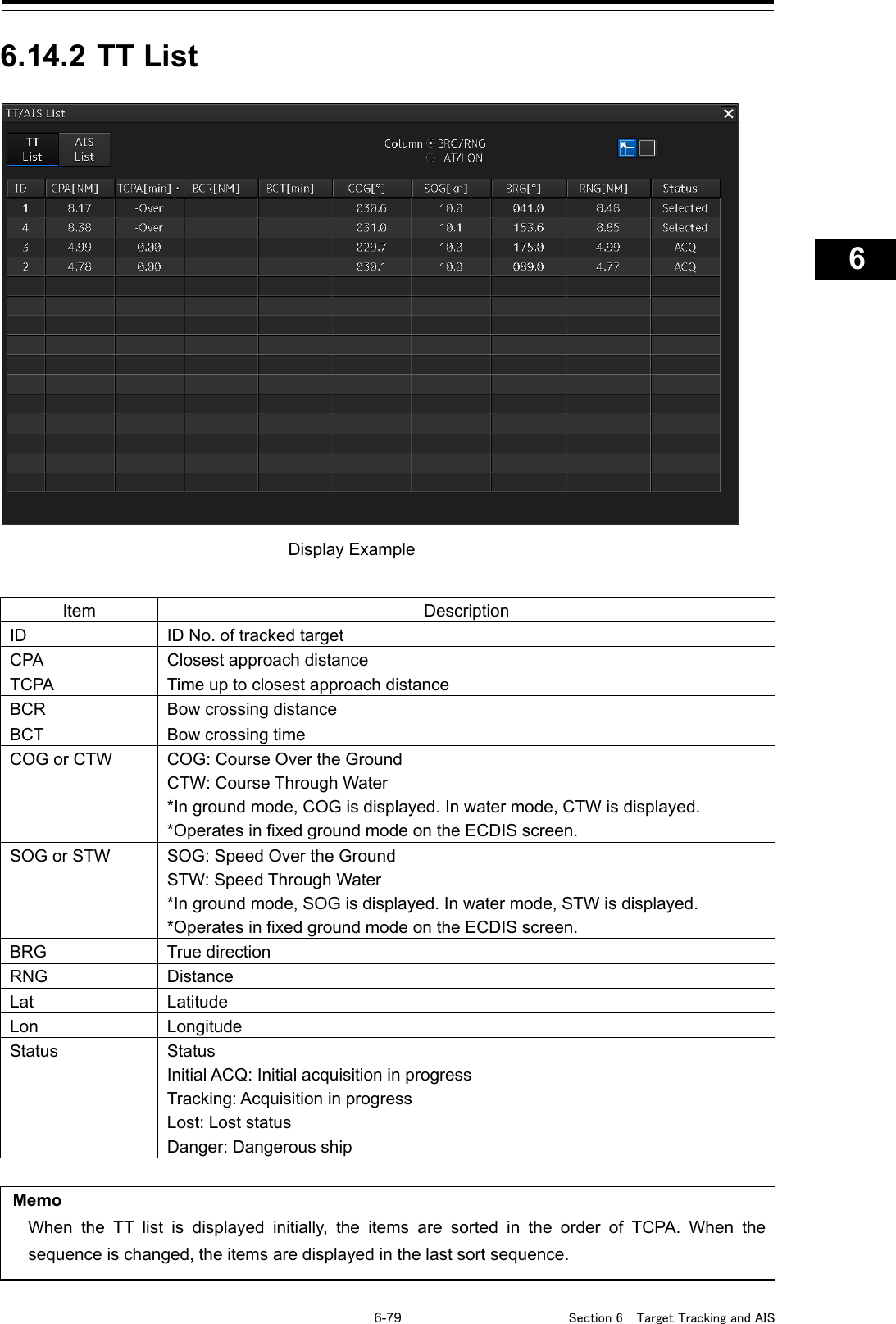
![Section 6 Target Tracking and AIS 6-80 6.14.3 AIS List Item Description ID ID No. of AIS CPA Closest approach distance TCPA Time up to closest approach distance COG or CTW COG: Course Over the Ground CTW: Course Through Water *In ground mode, COG is displayed. In water mode, CTW is displayed. *Operates in fixed ground mode on the ECDIS screen. SOG or STW SOG: Speed Over the Ground STW: Speed Through Water *In ground mode, SOG is displayed. In water mode, STW is displayed. *Operates in fixed ground mode on the ECDIS screen. Name Ship name Call Sign Call sign MMSI Maritime Mobile Service Identity BCR Bow crossing distance BCT Bow crossing time BRG True direction RNG Distance HDG Heading Lat Latitude When [CTW/STW/Name/Call Sign/MMSI] is clicked, CTW, STW, Name, Call Sign, and MMSI are displayed in the rows of list. When [BCR/BCT/BRG/RNG/HDG/POSN/Status] is clicked, BCR, BCT, Bearing, Range, Heading, Lat, Lon, and Status are displayed in the row of list. Display Example](https://usermanual.wiki/Japan-Radio/NKE2632.Instruction-Manual-Funtion-Part-1/User-Guide-2791060-Page-134.png)
![6-81 Section 6 Target Tracking and AIS 1 2 3 4 5 6 7 8 9 10 11 12 13 14 15 16 17 18 19 20 21 22 23 24 25 26 27 Item Description Lon Longitude Status Status Sleeping: Sleeping in progress Activated: Activation in progress Lost: Lost status Danger: Dangerous ship [Show AIS Detail] button When one item is selected from the list and this button is clicked, AIS detail information is displayed in the information monitoring window. For the details, refer to "2.3.1.4 AIS Detail INFO".](https://usermanual.wiki/Japan-Radio/NKE2632.Instruction-Manual-Funtion-Part-1/User-Guide-2791060-Page-135.png)
![Section 6 Target Tracking and AIS 6-82 6.15 Confirming Own Ship's AIS Information Take the following steps to display own ship's AIS information. 1 Click on the [Menu] button on the left toolbar. The menu is displayed. 2 Click on [TT/AIS] - [Own Ship AIS Data] on the menu. The "Information Reference" (information monitoring window) is displayed. 3 Click on the [Own Ship AIS Data] button. Own ship's AIS information is displayed in the information monitoring window. Memo The Information Reference can be switched to standard window display or extended window display. In the above example, the extended window is used. For the details of switching between the standard window and the extended window, refer to "2.3.2.1 Switching between a standard window and an extended window". Ship-specific static information Dynamic information Static information that may change during each navigation](https://usermanual.wiki/Japan-Radio/NKE2632.Instruction-Manual-Funtion-Part-1/User-Guide-2791060-Page-136.png)
![6-83 Section 6 Target Tracking and AIS 1 2 3 4 5 6 7 8 9 10 11 12 13 14 15 16 17 18 19 20 21 22 23 24 25 26 27 6.16 Displaying the Last Lost AIS Target 1 Click on the [Menu] button on the left toolbar. The menu is displayed. 2 Click on [TT/AIS] - [Last Lost AIS Data] on the menu. The "Information Reference" (information monitoring window) is displayed. 3 Click on the [Last Lost AIS Target] button. The last lost information about AIS target is displayed in the information monitoring window. Memo The Information Reference can be switched to standard window display or extended window display. In the above example, the extended window is used. For the details of switching between the standard window and the extended window, refer to "2.3.2.1 Switching between a standard window and an extended window". Last Lost AIS Target (last lost information about AIS target) Ship-specific static information Static information that may change during each navigation Dynamic information](https://usermanual.wiki/Japan-Radio/NKE2632.Instruction-Manual-Funtion-Part-1/User-Guide-2791060-Page-137.png)