Japan Radio NKE2632 Solid State S-Band Marine Radar User Manual Instruction Manual Operation Part 3
Japan Radio Co Ltd. Solid State S-Band Marine Radar Instruction Manual Operation Part 3
Contents
- 1. Installation Manual Part 1
- 2. Installation Manual Part 2
- 3. Installation Manual Part 3
- 4. Installation Manual Part 4
- 5. Installation Manual Part 5
- 6. Installation Manual Part 6
- 7. Installation Manual Part 7
- 8. Installation Manual Part 8
- 9. Installation Manual Part 9
- 10. Installation Manual Part 10
- 11. Installation Manual Part 11
- 12. Instruction Manual Operation Part 1
- 13. Instruction Manual Operation Part 2
- 14. Instruction Manual Operation Part 3
- 15. Instruction Manual Operation Part 4
- 16. Instruction Manual Funtion Part 1
- 17. Instruction Manual Funtion Part 2
- 18. Instruction Manual Funtion Part 3
- 19. Instruction Manual Funtion Part 4
- 20. Instruction Manual Funtion Part 5
- 21. Instruction Manual Funtion Part 6
Instruction Manual Operation Part 3
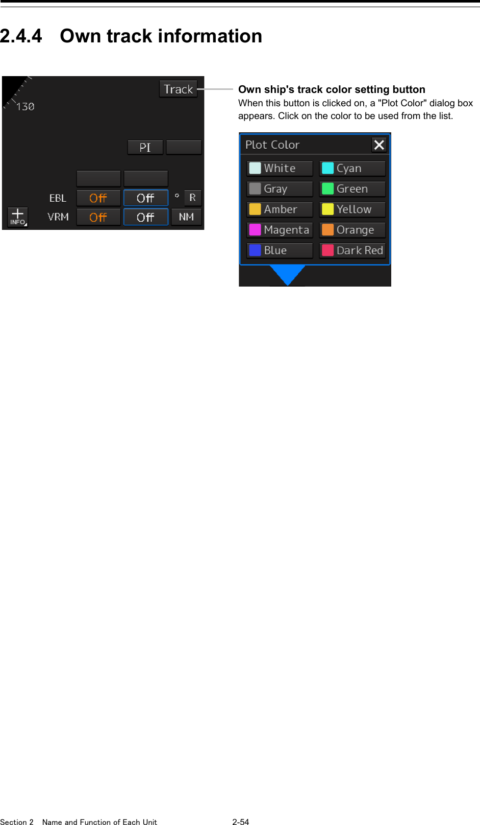
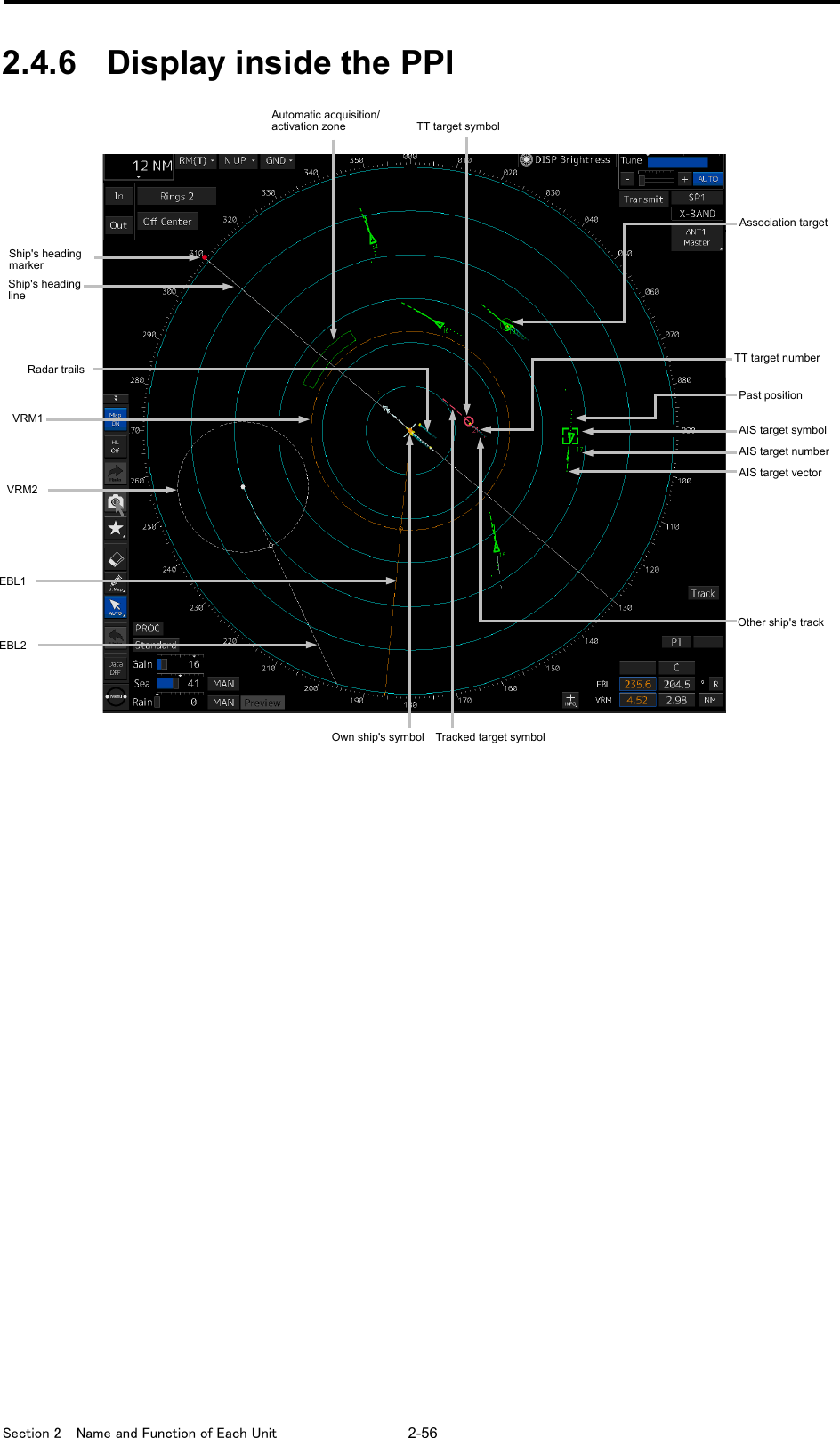
![2-55 Section 2 Name and Function of Each Unit 1 2 3 4 5 6 7 8 9 10 11 12 13 14 15 16 17 18 19 20 21 22 23 24 25 APP A APP B 1 2.4.5 Other ship information [Filter] button When the cursor is placed on this button while AIS is On, the AIS Filter status is displayed. The following status is displayed. Filter type •Filter shape: For Sector, the status is displayed with Start Angle and End Angle, and for Ring, the status is displayed with Distance. •Filtering mode: Priority or Display [AIS] button This button sets the AIS function to On/Off. On: Off: Note When AIS is set to Off, alerts relating to AIS are also no longer displayed. [1] Trail True/Relative switching button This button switches the trail mode to True or Relative. When True is set, "T" is displayed on the button and when Relative is set, "R" is displayed on the button. [2] Trail length switching combo box This button switches the trail length. For the details, refer to "5.4.9 Displaying radar trails (Trails)". [3] [CLR] (Trail Clear) button When this button is clicked on, the trail is cleared. For the details, refer to "5.4.9 Displaying radar trails (Trails)". [1] [2] [1] [2] [3] [1] Vector past position True/Relative switching button This button switches the vector past position to True or Relative. For the details, refer to "6.4.2.4 Setting the vector length". [2] Vector length input box Enter a vector length. For the details, refer to "6.4.2.4 Setting the vector length". [3] Past position interval switching combo box For the details, refer to "6.8.1 Setting the Past position". [1] CPA limit value input box Input a CPA limit value. For the details, refer to "6.4.3 Setting collision decision criteria". [2] TCPA limit value input box Input a TCPA limit value. For the details, refer to "6.4.3 Setting collision decision criteria". [2] [3] [1]](https://usermanual.wiki/Japan-Radio/NKE2632.Instruction-Manual-Operation-Part-3/User-Guide-2791058-Page-2.png)
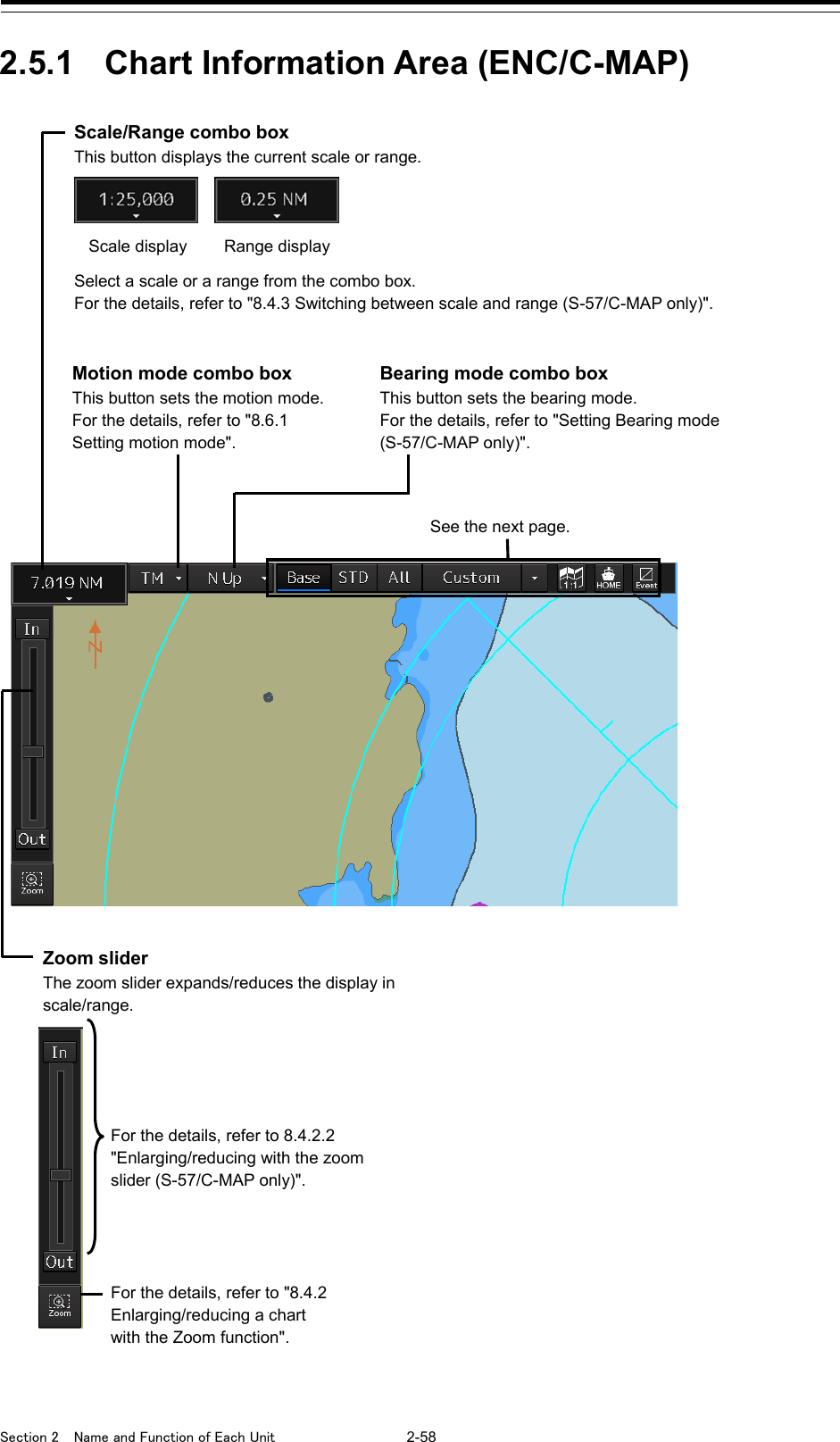
![2-59 Section 2 Name and Function of Each Unit 1 2 3 4 5 6 7 8 9 10 11 12 13 14 15 16 17 18 19 20 21 22 23 24 25 APP A APP B 1 Original scale display button When this button is clicked on, the screen scale is changed according to the original scale of the chart that is displayed at the center of the screen. [Home] button When this button is clicked on, the chart screen moves to the position at which the own ship’s position is to be displayed. For the details, refer to "8.3.1 Moving the chart with the [HOME] button". [Event] button When this button is clicked on, an event mark is assigned at the own ship’s position. For the details, refer to "8.12 Marking the Position of Own Ship with an Event Mark". Display category Set the display category of the chart. For the details, refer to "8.5 Changing the Object Category (S-57/C-MAP Only)".](https://usermanual.wiki/Japan-Radio/NKE2632.Instruction-Manual-Operation-Part-3/User-Guide-2791058-Page-6.png)
![Section 2 Name and Function of Each Unit 2-60 2.5.2 Chart Information Area (RNC) Scale/Range button This button displays the current scale. The scale cannot be changed. Motion mode combo box This button sets the motion mode. For the details, refer to "8.6.1 Setting motion mode". [Large] (Zoom In) / [Small] (Zoom Out) button This button switches the chart scale between Large and Small For the details, refer to "8.4.2.3 Enlarging/reducing with the Large/Small buttons (RNC only)". See the next page. RNC information display This area shows the geodetic datum and the original scale of the chart that is displayed. Original scale Geodetic datum](https://usermanual.wiki/Japan-Radio/NKE2632.Instruction-Manual-Operation-Part-3/User-Guide-2791058-Page-7.png)
![2-61 Section 2 Name and Function of Each Unit 1 2 3 4 5 6 7 8 9 10 11 12 13 14 15 16 17 18 19 20 21 22 23 24 25 APP A APP B 1 2.5.3 Sub Information Area Chart offset amount display When this button is clicked on, the chart offset amount is displayed on the dialog box. Chart selection button Select a chart from the "Select chart" dialog box that is displayed by clicking on this button. For the details, refer to "8.9.1 Selecting charts from all". [Home] button When this button is clicked on, the chart screen is moved to the position at which the own ship’s position is displayed. For the details, refer to "8.3.1 Moving the chart with the [HOME] button". [Event] button When this button is clicked on, an event mark is assigned at the own ship’s position. For the details, refer to "8.12 Marking the Position of Own Ship with an Event Mark". Memo • The display position of Sub Information Area varies according to the display size. 26inch screen (WUXGA) 19inch screen (SVGA) Display position Display position](https://usermanual.wiki/Japan-Radio/NKE2632.Instruction-Manual-Operation-Part-3/User-Guide-2791058-Page-8.png)
![Section 2 Name and Function of Each Unit 2-62 Memo The tab that is displayed varies depending on the setting. To set up, select [View] - [Options] - [Control] on the menu. For the details, refer to "16.2.15 Setting up Display of Own Ship Track Control, Display Format of Own Ship/Cursor Position and Display of Sub-Information Dialog". [1] [Watch] (Monitoring) window Switching tab When this tab is clicked on, the contents of the dialog are switched. [1] [Watch] (Monitoring) dialog [2] [POSN DIFF] (Position/distance difference) dialog [3] [Depth] (Depth) dialog [4] [Current] (Current) dialog [a] TT1 display button This button displays the TT1 On/Off status and switches the status. Whenever this button is clicked on, the display is switched to On/Off. On: Off: [b] TT2 display button This button displays the TT2 On/Off status and switches the status. Whenever this button is clicked on, the display is switched to On/Off. On: Off: [Vector(T)] input box Enter a vector length. Input range: 1 to 120 Radar Overlay display button This button displays the Radar Overlay On/Off status and switches the status. Whenever this button is clicked on, the display is switched to On/Off. On: Off: [When there are multiple radars] Select a Radar Overlay to be used from the combo box. [a] AIS button This button displays the AIS On/Off status and switches the status. Whenever this button is clicked on, the display is switched to On/Off. On: Off: [b] [Filter] status display When AIS is set to On, if placing the cursor on this button, the AIS filter status is displayed. [a] [b] [a] [b] Note When the button is turned OFF, even the alerts related to the radar will not be displayed. Note When the button is turned OFF, even the alerts related to the AIS will not be displayed. Note When the button is turned OFF, even the alerts related to the TT will not be displayed. Note When the button is turned OFF, even the alerts related to the TT will not be displayed.](https://usermanual.wiki/Japan-Radio/NKE2632.Instruction-Manual-Operation-Part-3/User-Guide-2791058-Page-9.png)
![2-63 Section 2 Name and Function of Each Unit 1 2 3 4 5 6 7 8 9 10 11 12 13 14 15 16 17 18 19 20 21 22 23 24 25 APP A APP B 1 Display names of the TT1 display button and the TT2 display button At the end of the display name, REL, GND, or SEA is displayed depending on the motion mode and stabilization mode. (Example: TT1-GND) Display characters Motion mode Stabilization mode REL Relative motion display (RM) – GND True motion display (TM) Ship speed relative to land SEA True motion display (TM) Ship speed relative to water To use a TTM sentence for TT symbol display, the OSD sentence must be received from RADAR. [2] [POSN DIFF] dialog Displays the difference of bearing and distance between POSN(Main) and POSN(Sub). [3] [Depth] dialog Displays the water depth. [POSN(Sub) Source] combo box Displays the source of the sub position. When there are multiple sub position sources, select a source from the combo box. [POSN Difference] Displays the difference of bearing and distance between POSN(Main) and POSN(Sub). [Source] Displays the depth sounder that is used. FWD: Depth sounder installed at the front of the ship MID: Depth sounder installed at the center of the ship AFT: Depth sounder installed at the rear of the ship None: Hides the [Depth] tab. When a depth sounder is not installed, the [Depth] tab is not displayed. [Measured from] Displays the water depth measurement reference position. Transducer: Transducer Surface: Water surface Keel: Keel [Depth] Displays the water depth.](https://usermanual.wiki/Japan-Radio/NKE2632.Instruction-Manual-Operation-Part-3/User-Guide-2791058-Page-10.png)
![Section 2 Name and Function of Each Unit 2-64 [4] [Current] dialog Displays the bearing and speed of the current. 2.5.4 ARCS PIN input dialog box When an ARCS chart is imported, a dialog box for entering an ARCS PIN is displayed at the startup of the ECDIS mode. For the details, refer to "8.2.3 Entering an ARCS PIN Number (ARCS Only)". [Set] Displays the bearing of the current. [Drift] Displays the speed of the current.](https://usermanual.wiki/Japan-Radio/NKE2632.Instruction-Manual-Operation-Part-3/User-Guide-2791058-Page-11.png)
![Section 3 Common Basic Operations 3-10 3.4 Basic Menu Operations Various functions can be executed or set from the menu that is displayed by clicking on the [Menu] button. This section describes the basic menu operations. 3.4.1 Opening the menu 1 Click on the [Menu] button on the left toolbar. The menu is displayed. [For RADAR] The menu screen comprises two pages. Page switching button: Switch the menu screen by clicking on the button. [Menu] button](https://usermanual.wiki/Japan-Radio/NKE2632.Instruction-Manual-Operation-Part-3/User-Guide-2791058-Page-21.png)
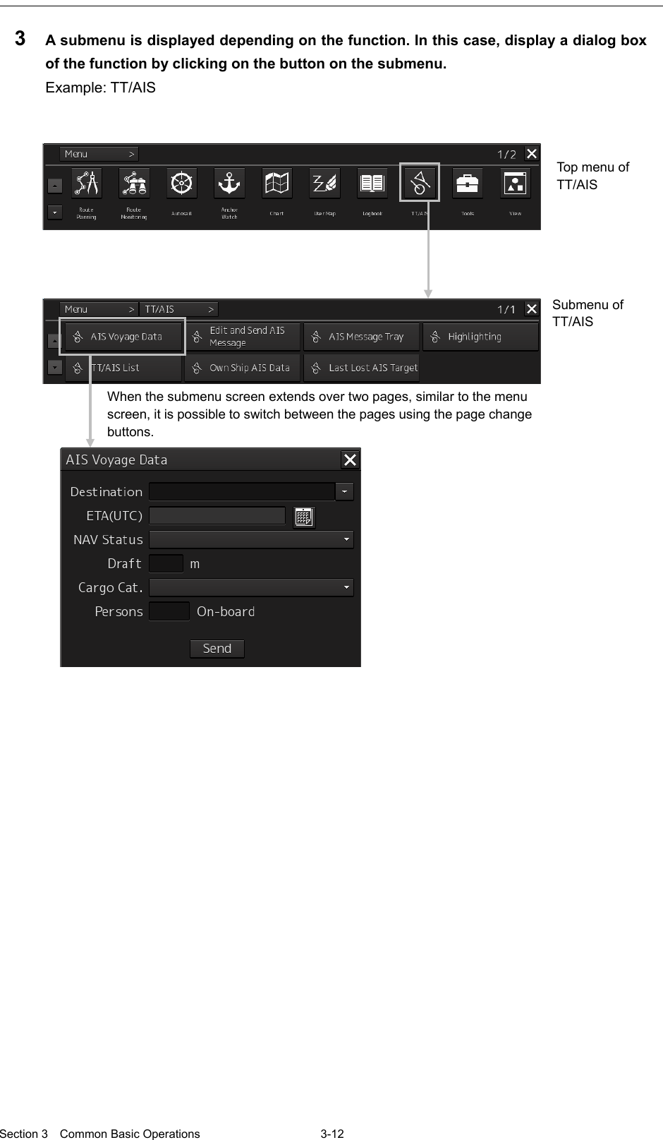
![3-11 Section 3 Common Basic Operations 1 2 3 4 5 6 7 8 9 10 11 12 13 14 15 16 17 18 19 20 21 22 23 24 25 APP A APP B 1 [For ECDIS] The menu screen comprises two pages. Page switching button: Switch the menu screen by clicking on the button. 2 Click on one of the buttons that are displayed on the menu. A dialog box for executing or setting the applicable function appears. Display Example](https://usermanual.wiki/Japan-Radio/NKE2632.Instruction-Manual-Operation-Part-3/User-Guide-2791058-Page-22.png)
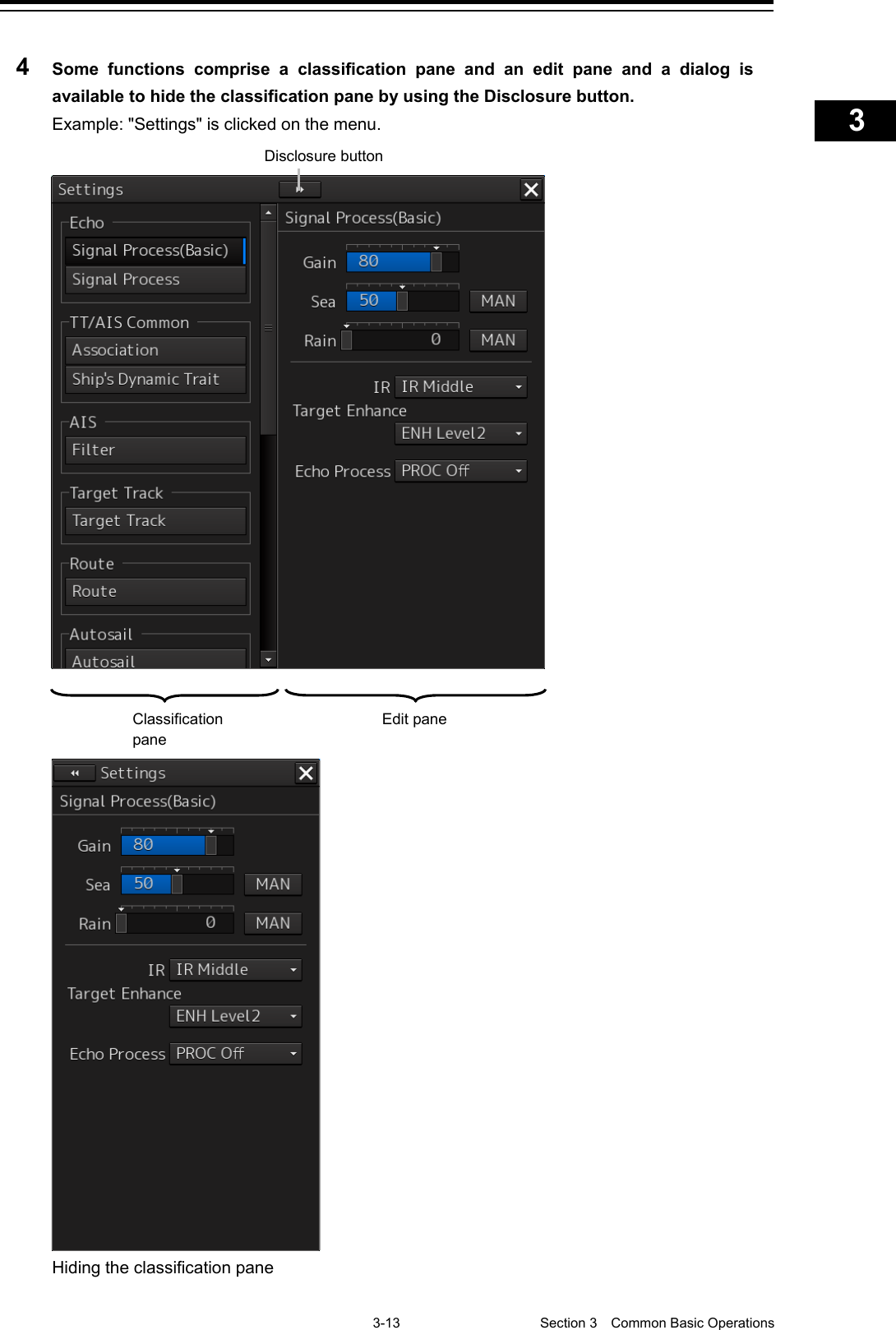
![Section 3 Common Basic Operations 3-14 Memo When the RADAR transmission status is Transmit in RADAR mode and Classification is selected, the classification pane is hidden automatically. 3.4.2 Menu list The menus that are displayed vary according to the task that is currently being executed. Menu Task that is currently executed (: Display -: Hide) Related section ECDIS RADAR Conning Playback Route Planning - - - Section 9 Route Planning Route Monitoring - Section 10 Route Monitoring Anchor Watch - - Section 11 Monitoring a Dragging Anchor Autosail*2 - - - Section 12 Automatic Sailing (option) Chart *1 - Section 13 Operating a Chart User Map - Section 14 Creating a User Map/ Updating a Chart Logbook - - - Section 15 Logbook TT/AIS - Section 6 Target Tracking and AIS Tools - - View Section 16 Setting Up Screen View Alert - Section 17 Setting Up Alerts Settings Section 18 Setting Up the Operation Mode Chart Maintenance *1 - - 13.10 Maintaining a Chart Maintenance 21.1 Maintenance Functions Executed from Menu Help 3.17 Help Code Input 3.18 Password Input Service - Section 19 Adjusting and Setting Up Equipment (for Services) *1: Displayed when the chart display option is attached to RADAR. *2: Displayed when the automatic sailing option is attached. 3.4.3 Closing the menu Click on the [X] button on the menu (submenu).](https://usermanual.wiki/Japan-Radio/NKE2632.Instruction-Manual-Operation-Part-3/User-Guide-2791058-Page-25.png)
![3-15 Section 3 Common Basic Operations 1 2 3 4 5 6 7 8 9 10 11 12 13 14 15 16 17 18 19 20 21 22 23 24 25 APP A APP B 1 3.5 Basic Dialog Box Operations When a dialog box is opened, the dialog box is in the factory setting state or state at termination of the previous operation. The setting can be changed by the following operation. • Enter a character or a value in the input box. • Select a setting from the list. • Select a setting by clicking on the button. • Select a setting by checking or unchecking the check box. 3.5.1 Changing dialog box settings This section describes the basic setting change procedure by using the "Edit and Send AIS Message" (AIS message editing/transmission) dialog box as the example. [Addressed]/ [Broadcast] radio button: Select whether a MMSI message is to be sent or a broadcast message is distributed by clicking on the radio button. Message input area: Enter a message (characters). [MMSI] box: Enter a MMSI code (value). [Message Category] list: Select [Safety Message] or [Routine Message] from the list.](https://usermanual.wiki/Japan-Radio/NKE2632.Instruction-Manual-Operation-Part-3/User-Guide-2791058-Page-26.png)
![Section 3 Common Basic Operations 3-16 A function may also be set by opening another dialog box from the dialog box. 3.5.2 Closing a dialog box Close the dialog box by clicking on the [X] (Close) button on the dialog box. Memo When no operation is performed for one minute after a dialog*1 is displayed, the dialog is closed automatically. When a different dialog is displayed in any of the following cases, the dialog that is currently displayed is closed automatically. • The RADAR transmission status is Transmit in RADAR mode. • Automatic sailing or route monitoring is carried out in ECDIS mode. If setting/editing operation has not been completed when the dialog is closed automatically, the editing contents are discarded. *1 The following dialogs are excluded from the targets. Information monitoring window, information reference window, route monitoring (including Voyage Information, Voyage Calculation, and Pair of data), MOB, and Wave Spectrum [Read only] check box: Specify the file as [Read Only] by checking the box by clicking. File operation dialog box display button: When this button is clicked on, the "File operation" dialog box is opened. [X] button](https://usermanual.wiki/Japan-Radio/NKE2632.Instruction-Manual-Operation-Part-3/User-Guide-2791058-Page-27.png)
![Section 3 Common Basic Operations 3-18 3.6 Operation of the Information Monitor Window This section describes the operation and editing of the information monitor window. For the details of the information monitor window, refer to "2.3 Common Information Window". 3.6.1 Opening the information monitor window 1 Click on the page switching button on the initial display window. In the initial display, a blank window appears. The "Page Selection" dialog box appears by clicking on the page switching button. [For RADAR] Page switching button](https://usermanual.wiki/Japan-Radio/NKE2632.Instruction-Manual-Operation-Part-3/User-Guide-2791058-Page-29.png)
![3-19 Section 3 Common Basic Operations 1 2 3 4 5 6 7 8 9 10 11 12 13 14 15 16 17 18 19 20 21 22 23 24 25 APP A APP B 1 [For ECDIS] 2 Click on the monitor information to be displayed. The applicable window is opened. Page switching button Example: When selecting the TT List in the RADAR Click.](https://usermanual.wiki/Japan-Radio/NKE2632.Instruction-Manual-Operation-Part-3/User-Guide-2791058-Page-30.png)
![Section 3 Common Basic Operations 3-20 Returning to the "Page Selection" dialog box from each window When the page switching button on each window is clicked on, control returns to the "Page Selection" dialog box. Setting another window for the item (ECDIS only) 1 Select the checkbox for the item for which another window is to be set. 2 Click on the [New Window] button. The item is displayed on another window. Memo The window that is already displayed cannot be set to another window. Example: Returning control from Target INFO in the RADAR Click.](https://usermanual.wiki/Japan-Radio/NKE2632.Instruction-Manual-Operation-Part-3/User-Guide-2791058-Page-31.png)
![3-21 Section 3 Common Basic Operations 1 2 3 4 5 6 7 8 9 10 11 12 13 14 15 16 17 18 19 20 21 22 23 24 25 APP A APP B 1 3.6.2 Displaying an information monitor window from other than the "Page Selection" dialog box Use the following procedures to display an information monitor window from a display other than the "Page Selection" dialog box. Information monitor window Display method Target INFO 1) Click on the TT symbol. (Cursor AUTO mode) 2) Click the right button on the TT/AIS symbol and select Readout information from the context menu. 3) Click on the AIS Activated target. (Cursor AUTO mode) TT List (RADAR) TT1 List, TT2 List (ECDIS) 1) Select TT/AIS List from [TT/AIS] on the menu. AIS List 1) Select TT/AIS List from [TT/AIS] on the menu. AIS Detail INFO 1) Select one AIS target from the AIS List and click on the Details button. 2) Click the right button on the AIS symbol, and select Readout detail information from the context menu.](https://usermanual.wiki/Japan-Radio/NKE2632.Instruction-Manual-Operation-Part-3/User-Guide-2791058-Page-32.png)
![3-23 Section 3 Common Basic Operations 1 2 3 4 5 6 7 8 9 10 11 12 13 14 15 16 17 18 19 20 21 22 23 24 25 APP A APP B 1 3.7.1 Stopping a buzzer To stop a buzzer (silencing), click the silence button in the alert notification area or press the [SILENCE] key in the trackball operation unit. 3.7.2 Confirming alert contents Display Example when an Alert is generated Display Example when No Alert is generated When an alert is generated, the alert message is displayed in the "Alert status area". The alert type and the number of alerts are displayed by the button. [SILENCE] key Silence button Warning button Alert status area Caution button Alarm button Warning button Caution button Alarm button](https://usermanual.wiki/Japan-Radio/NKE2632.Instruction-Manual-Operation-Part-3/User-Guide-2791058-Page-34.png)
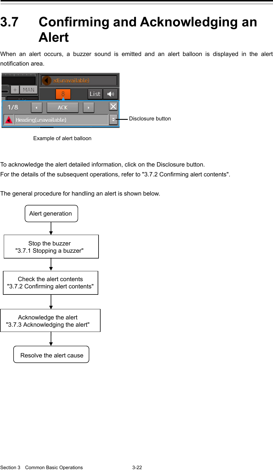
![Section 3 Common Basic Operations 3-24 • Alarm button: Displayed when an alarm is generated. The button is displayed in red. The number of alarms is indicated on the button • Warning button: Displayed when a warning is generated. The button is displayed in orange. The number of warnings is indicated on the button. • Caution button: Displayed when a caution is generated. The button is displayed in yellow. The number of cautions is indicated on the button. 1 Click on the button An alert balloon is displayed. 2 Display the alert detail dialog by clicking on the Disclosure button. [1] [Higher] button When the Higher button is clicked on, details of the alerts of the higher priority than the alert currently displayed appear. [2] [Lower] button When the Lower button is clicked on, details of the alerts of the lower priority than the alert currently displayed appear. [3] Disclosure button When the Disclosure button is clicked on, the original alert balloon is displayed. As a result, the Own Ship Information that was hidden can be re-acknowledged. Disclosure button [1] [2] [3] [4]](https://usermanual.wiki/Japan-Radio/NKE2632.Instruction-Manual-Operation-Part-3/User-Guide-2791058-Page-35.png)
![3-25 Section 3 Common Basic Operations 1 2 3 4 5 6 7 8 9 10 11 12 13 14 15 16 17 18 19 20 21 22 23 24 25 APP A APP B 1 [4] Detail information Cause, Status, Date and time (Raised), Details and action (Advice) to be taken are displayed. Memo About Information: Information is displayed in addition to a warning or a caution in the alert status area. Information is used to report operation errors and so on to the users. Unlike other alerts, no detail display is provided for Information.](https://usermanual.wiki/Japan-Radio/NKE2632.Instruction-Manual-Operation-Part-3/User-Guide-2791058-Page-36.png)
![Section 3 Common Basic Operations 3-26 3.7.3 Acknowledging the alert After the [ACK] (acknowledgement) button of the alert detail display dialog box is clicked on or the [ALERT ACK] (alert acknowledgement) button of the trackball operation section is pressed after verification of the alert contents, the alert that is currently displayed is acknowledged. When there are multiple alerts, perform the same operation by displaying the details dialog box of another alert. When all the alerts are acknowledged, the alert detail display dialog is closed automatically. Memo An alert can also be acknowledged by clicking on the [Active Alert] tab - [ACK] button of the "Alert List" dialog box. For the details, refer to "3.7.4 Displaying Alert List and Alert History". [ACK] button](https://usermanual.wiki/Japan-Radio/NKE2632.Instruction-Manual-Operation-Part-3/User-Guide-2791058-Page-37.png)
![Section 3 Common Basic Operations 3-28 ["Active Alert" tab] [1] Active alert information The number of current alerts is displayed. [2] Active page information Up to 20 alert information items can be displayed in one page. Use this function to switch pages when the number of alert information items exceeds 20, requiring multiple pages. Number of alerts Number of unacknowledged alerts Move to the first page Move to the last page Move to the previous page Move to the next page [1] [4] [2] [3]](https://usermanual.wiki/Japan-Radio/NKE2632.Instruction-Manual-Operation-Part-3/User-Guide-2791058-Page-39.png)
![3-29 Section 3 Common Basic Operations 1 2 3 4 5 6 7 8 9 10 11 12 13 14 15 16 17 18 19 20 21 22 23 24 25 APP A APP B 1 [3] Active alert list • The alert of the highest priority is automatically selected. When an alert in the active alert list is clicked on, the alert is selected. • The details of the selected alert are displayed in "[4] Active alert details". • When a new alert is generated during the screen display, the alert is added at the top of the list. • By clicking on any of the items in the title line, active alerts can be sorted based on the item. • When the [ACK] button is clicked on, the alert is acknowledged. Memo The [ACK] button is not displayed for the [Caution] alert since acknowledgement is not required.](https://usermanual.wiki/Japan-Radio/NKE2632.Instruction-Manual-Operation-Part-3/User-Guide-2791058-Page-40.png)
![Section 3 Common Basic Operations 3-30 [4] Details of active alert Details of the alert that is currently selected are displayed. Alert Detailed information Cause: Displays the cause of the alert. Raised: Displays the alert generation time. Details: Displays the details of the cause of the alert. Advice: Displays advice on the alert (action to be taken by the user). Acknowledged: Displays the time when the alert was acknowledged. Category: Displays the alert category. Priority: Displays the current alert priority (identification of Alarm/Warning/Caution). Original Priority: Displays the priority (identification of Alarm/Warning/Caution) at the generation of the alert. [Higher] button When this button is clicked on, the details of the alert of the higher priority than the alert that is currently displayed appear. [Lower] button When this button is clicked on, the details of the alert of the lower priority than the alert that is currently displayed appear. [ACK] button When this button is clicked on, the alert that is currently selected is acknowledged.](https://usermanual.wiki/Japan-Radio/NKE2632.Instruction-Manual-Operation-Part-3/User-Guide-2791058-Page-41.png)
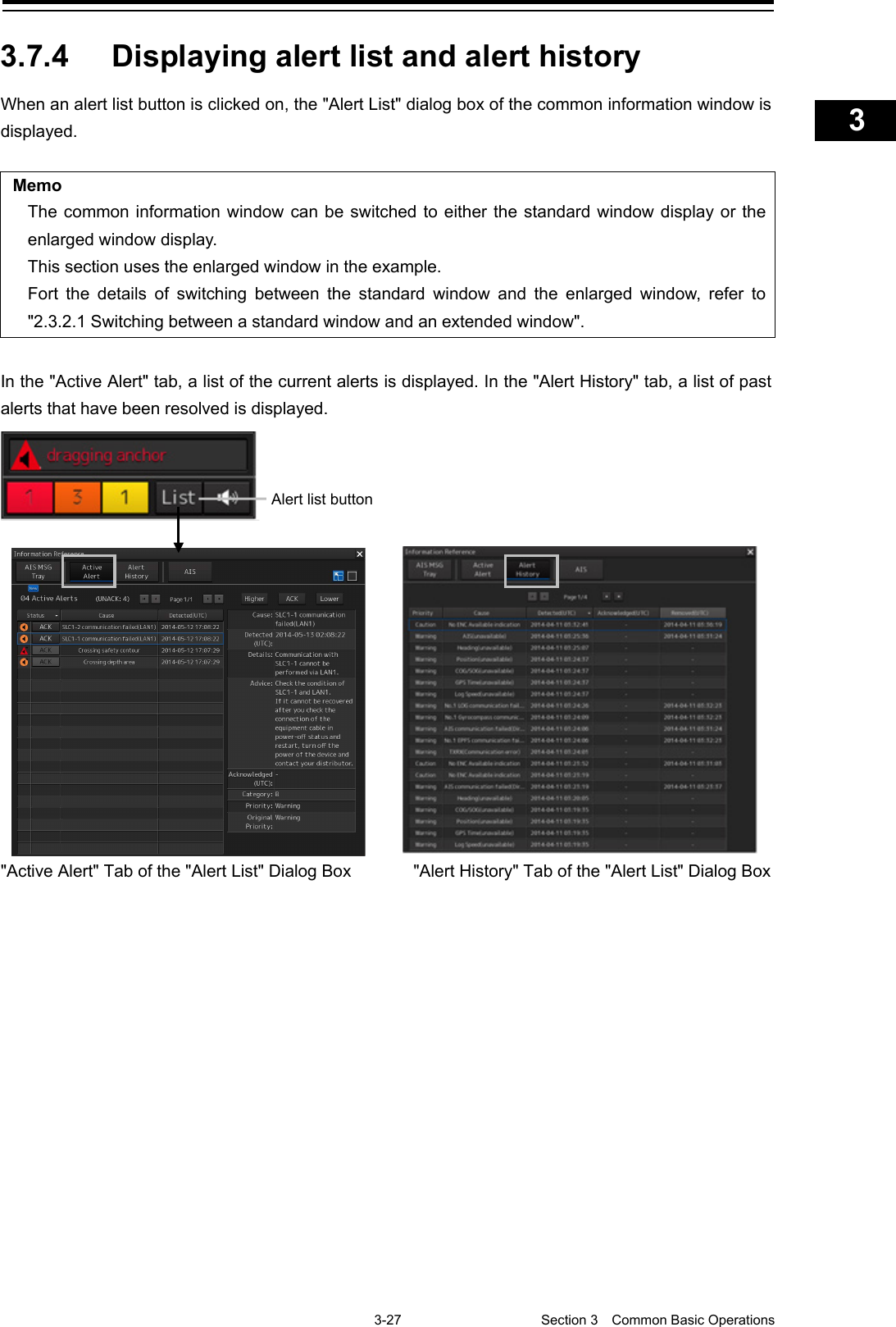
![3-31 Section 3 Common Basic Operations 1 2 3 4 5 6 7 8 9 10 11 12 13 14 15 16 17 18 19 20 21 22 23 24 25 APP A APP B 1 ["Alert History" tab] Alerts that have been generated in the past are displayed. • Up to 20 alerts are displayed per page. • When a newly acknowledged alert is generated during the screen display, the acknowledged alert is added to the top of the list. • By clicking on any of the items in the title line, active alerts can be sorted based on the item. Memo The Alert History screen is displayed under the extended window only. A standard window is not available.](https://usermanual.wiki/Japan-Radio/NKE2632.Instruction-Manual-Operation-Part-3/User-Guide-2791058-Page-42.png)
![Section 3 Common Basic Operations 3-32 3.8 Switching the Day/Night Mode The screen display color can be switched to any of five levels according to the brightness within the bridge. Use the following procedure for switching. 1 Click on the Day/Night button on the right toolbar. Adjustment buttons are displayed based on the brightness that is currently set. 2 Adjust the brightness by using the [Light] button and the [Dark] button. Whenever the [Light] button is clicked on, the brightness increases by one level from the current level. When the [Dark] button is clicked on, the brightness decreases by one level from the current level. : Day 1 : Day 2 : Day 3 : Dusk : Night Example: Day2 is set.](https://usermanual.wiki/Japan-Radio/NKE2632.Instruction-Manual-Operation-Part-3/User-Guide-2791058-Page-43.png)
![3-33 Section 3 Common Basic Operations 1 2 3 4 5 6 7 8 9 10 11 12 13 14 15 16 17 18 19 20 21 22 23 24 25 APP A APP B 1 Change of the color of the Day/Night button, particularly the use of the [Night] color, may interfere with the recognition of display information. Memo The colors and brightness of the buttons can be changed by setting [Settings] - [Color and Brightness] in the menu. For the details, refer to "18.18 Setting Color and Brilliance". Relationship between the day/night mode and the screen/operation section brightness setting value When the day/night mode is changed, the screen/operation section brightness is set to the following values. 26-inch monitor 19-inch monitor Screen brightness Day1, Day2, Day3: 67/100 Dusk: 60/100 Night: 11/100 Day1, Day2, Day3: 42/100 Dusk: 20/100 Night: 4/100 Operation unit brightness Day1: Level4 Day2: Level3 Day3: Level2 Dusk, Night: Level1](https://usermanual.wiki/Japan-Radio/NKE2632.Instruction-Manual-Operation-Part-3/User-Guide-2791058-Page-44.png)
![Section 3 Common Basic Operations 3-34 3.9 Adjusting the Brightness of the Screen and Operation Unit The brightness of the screen and the operation section can be adjusted. The screen brightness can be adjusted within the range from 0 to 100. The brightness of the operation section can be adjusted in 5 levels (0 to 4). Use the following procedure for adjusting the brightness. 1 Click on the Display and Panel Brightness button on the right toolbar. The following brightness buttons are displayed. 2 Adjust the brightness by using the [Light] button and the [Dark] button. Whenever the [Light] button is clicked on, the brightness increases by one level from the current level. Whenever the [Dark] button is clicked on, the brightness decreases by one level from the current level. Screen brightness Brightness of operation unit](https://usermanual.wiki/Japan-Radio/NKE2632.Instruction-Manual-Operation-Part-3/User-Guide-2791058-Page-45.png)
![3-35 Section 3 Common Basic Operations 1 2 3 4 5 6 7 8 9 10 11 12 13 14 15 16 17 18 19 20 21 22 23 24 25 APP A APP B 1 "Display Brightness" dialog If the [MULTI] dial is operated while [Display Brightness] function is selected as the [MULTI] dial assignment function, the "Display Brightness" dialog is displayed. It is possible to adjust the brightness of the display section by rotating the [MULTI] dial. In order to set an offset value so that when set to the same value as the screen brightness of other equipment, the light emitted becomes the same as in other equipment, click the [Advanced] button and adjust the offset using the buttons displayed for setting the [Offset].](https://usermanual.wiki/Japan-Radio/NKE2632.Instruction-Manual-Operation-Part-3/User-Guide-2791058-Page-46.png)
![Section 3 Common Basic Operations 3-36 3.10 MOB (Man Over Board) When a person falls overboard, this monitoring function prevents loss of sight of the position of the person overboard. The MOB use procedure is as follows. 1 Click on the MOB button on the right toolbar. The "Marker" dialog box appears and the MOB marker is displayed on the own ship’s position when the button is clicked on. Memo The "Marker" dialog box appears by clicking [Tools] - [MOB] on the menu 2 Monitor with the screen and the "Marker" dialog box. The position relationship between the own ship that is moving and the MOB marker is displayed as follows. "Marker" Dialog Box MOB marker Position and bearing from own ship Own ship's symbol](https://usermanual.wiki/Japan-Radio/NKE2632.Instruction-Manual-Operation-Part-3/User-Guide-2791058-Page-47.png)
![3-37 Section 3 Common Basic Operations 1 2 3 4 5 6 7 8 9 10 11 12 13 14 15 16 17 18 19 20 21 22 23 24 25 APP A APP B 1 See below for how to reference the "Marker" dialog box. [1] [Position] Displays the coordinate of the MOB marker. [2] [Bearing] Displays the bearing from the own ship to the MOB marker. [3] [Range] Displays the range from the own ship to the MOB marker. [4] NM/Km/sm switching button Whenever this button is clicked on, the unit of [Range] is switched to NM, km or sm. Memo NM denotes nautical mile, sm denotes statute mile, and km denotes kilometer. [5] [TTG] Displays the time to reach the MOB marker from the ship speed. [6] [Time] Displays the time elapsed after clicking on the [MOB] button. [1] [2] [3] [5] [6] [4]](https://usermanual.wiki/Japan-Radio/NKE2632.Instruction-Manual-Operation-Part-3/User-Guide-2791058-Page-48.png)
![Section 3 Common Basic Operations 3-38 To exit from MOB 1 Click the [X] button in the Marker dialog box. A confirmation dialog box appears. 2 Click on the [OK] button. The "Marker" dialog is closed. The MOB marker is cleared](https://usermanual.wiki/Japan-Radio/NKE2632.Instruction-Manual-Operation-Part-3/User-Guide-2791058-Page-49.png)