Jorjin Technologies WG1300E00 Wireless LAN EM board for Module (802.11 bg) User Manual CC3000 WG1300E00 UG R01 20120302
Jorjin Technologies Inc. Wireless LAN EM board for Module (802.11 bg) CC3000 WG1300E00 UG R01 20120302
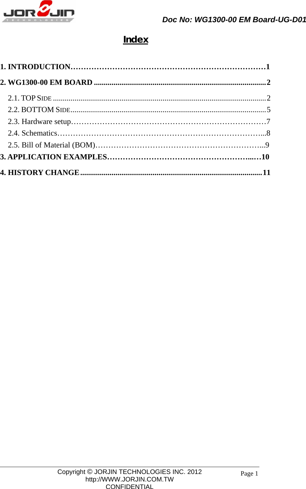
Contents
- 1. User Manual
- 2. User Manual - Statements
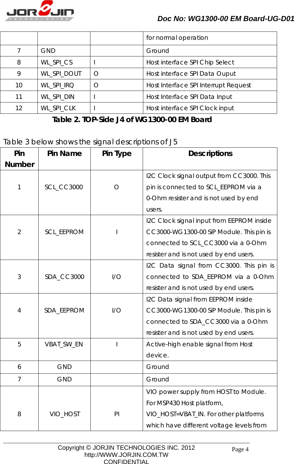
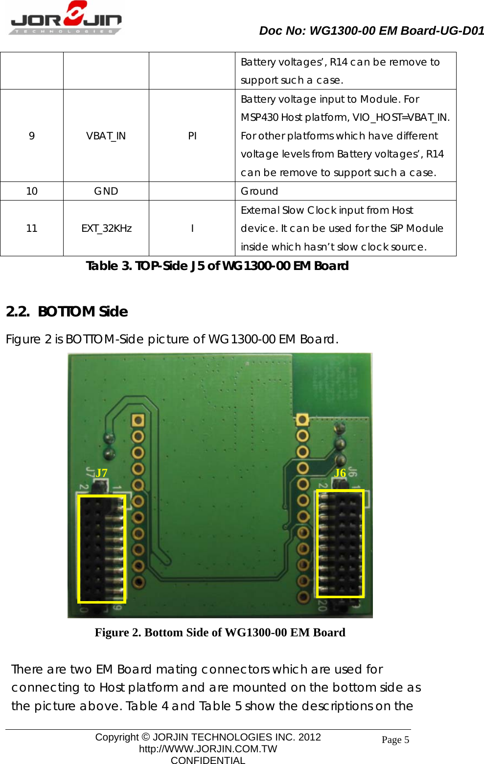
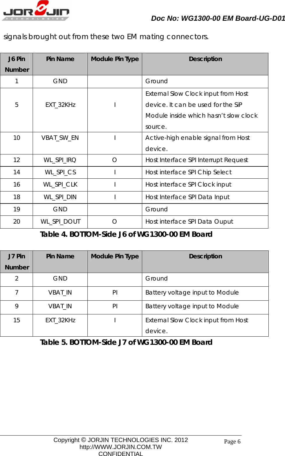
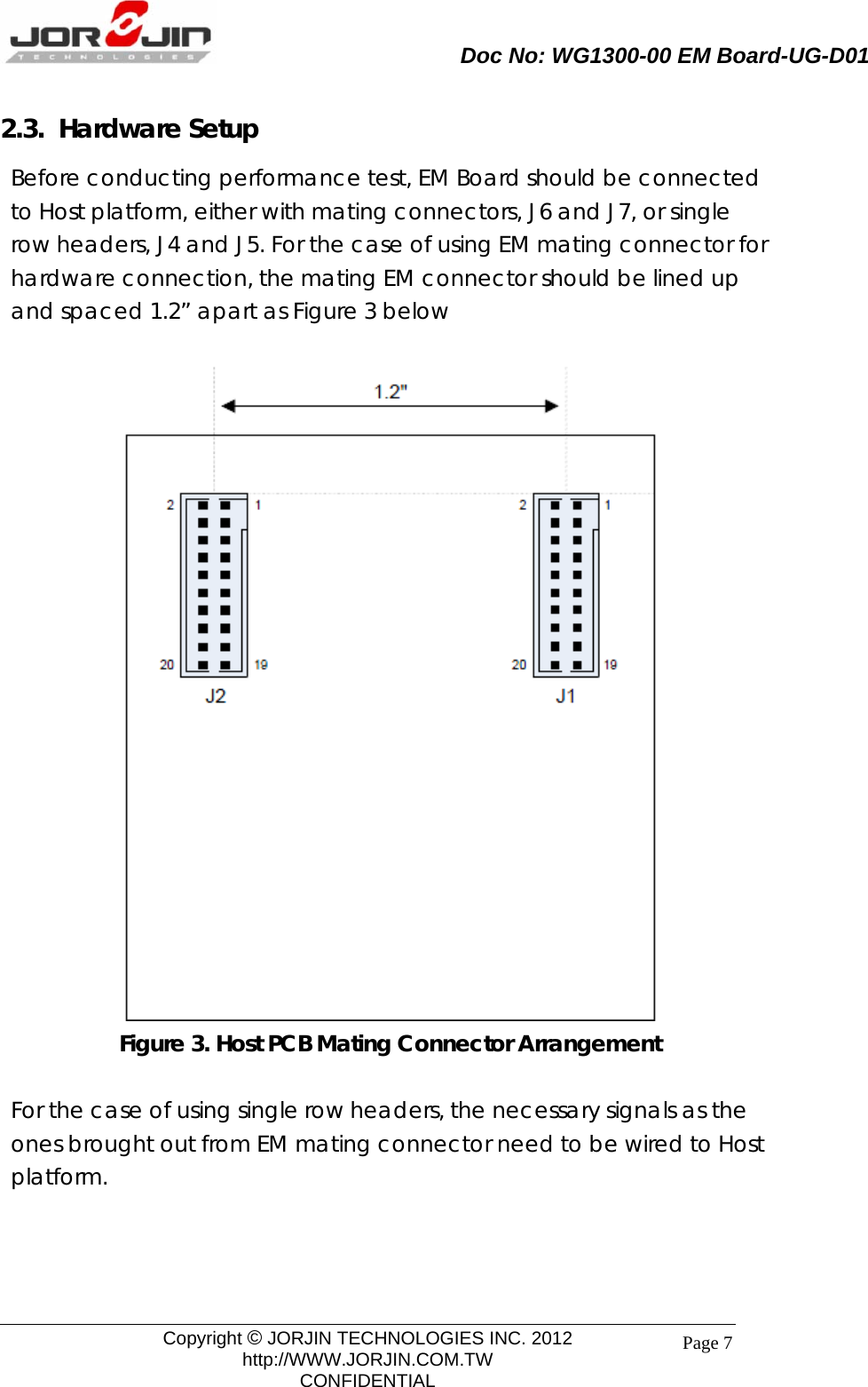
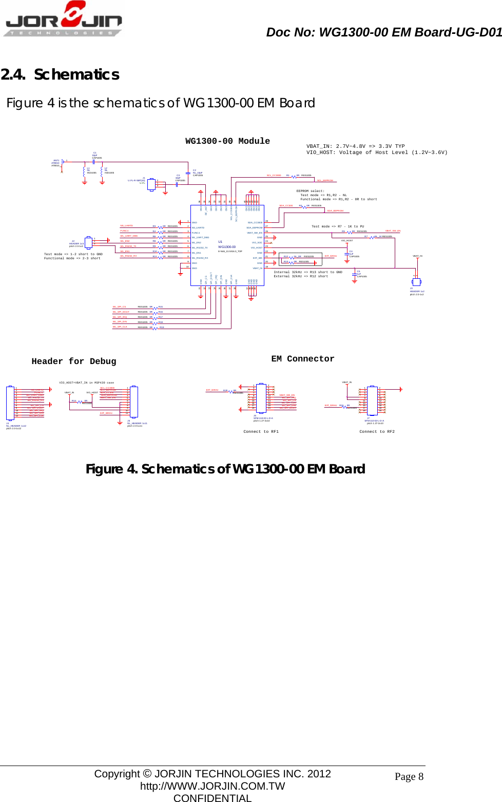
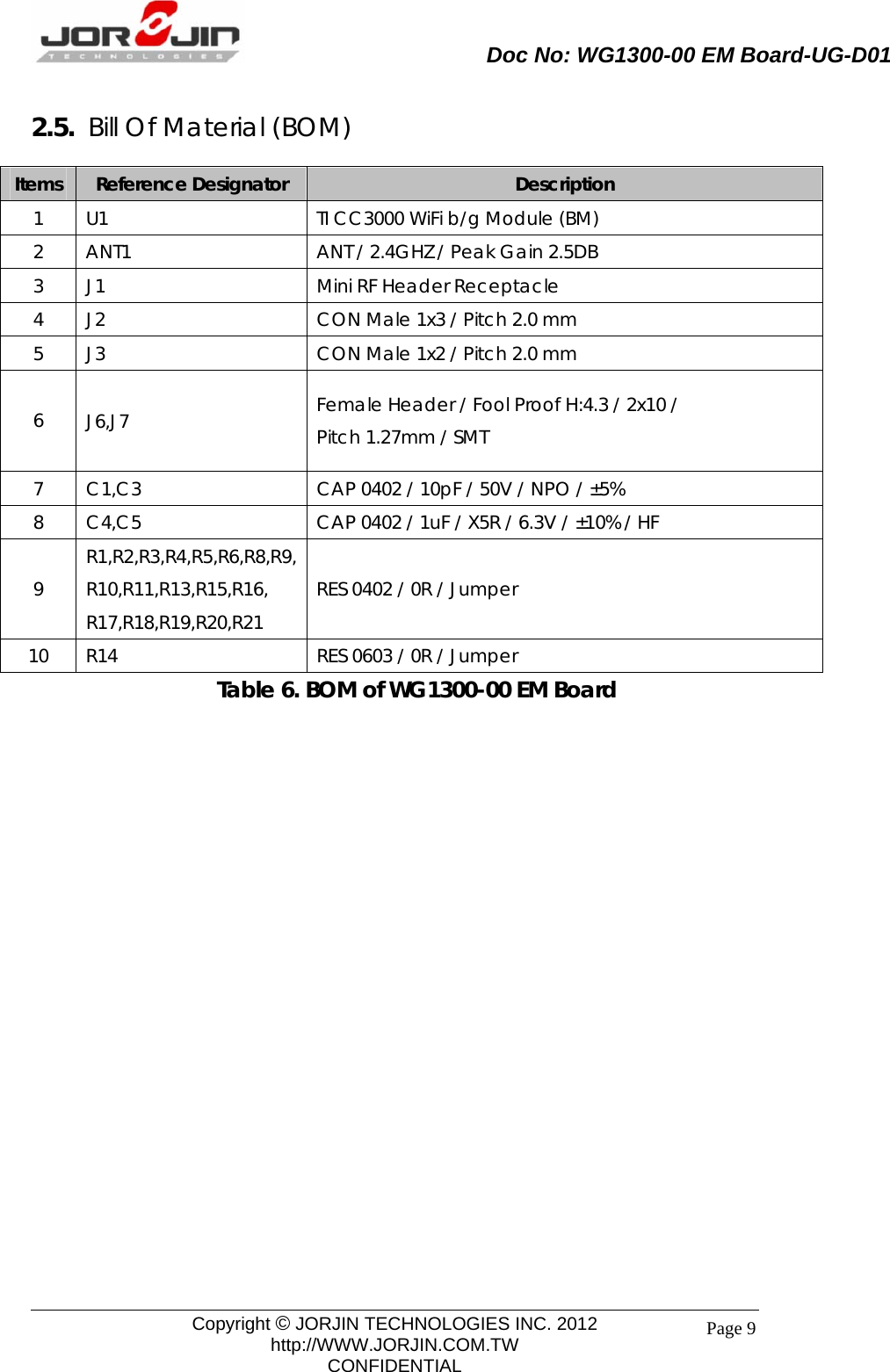
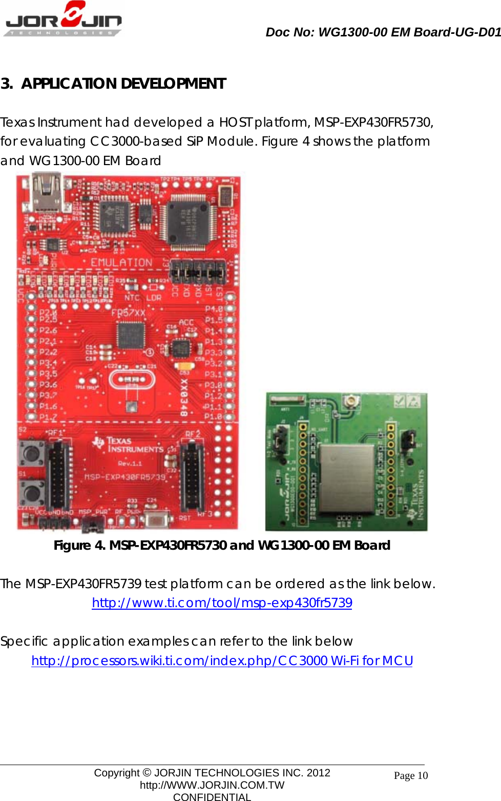
User Manual