Jotron AS TR8000 Tron AIS TR-8000 User Manual Operator and Installation Manual part 1
Jotron AS Tron AIS TR-8000 Operator and Installation Manual part 1
Contents
- 1. Technical Manual
- 2. Operator and Installation Manual part 1
- 3. Operator and Installation Manual part1
- 4. Operator and Installation Manual part 2
- 5. Operator and Installation Manual part 3
Operator and Installation Manual part 1


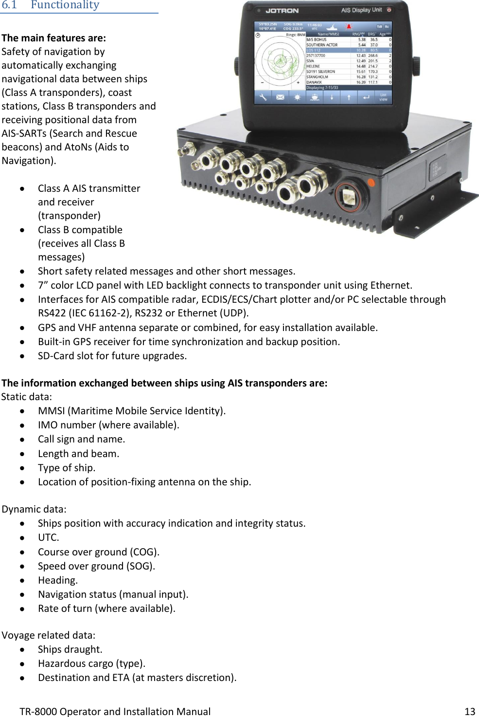


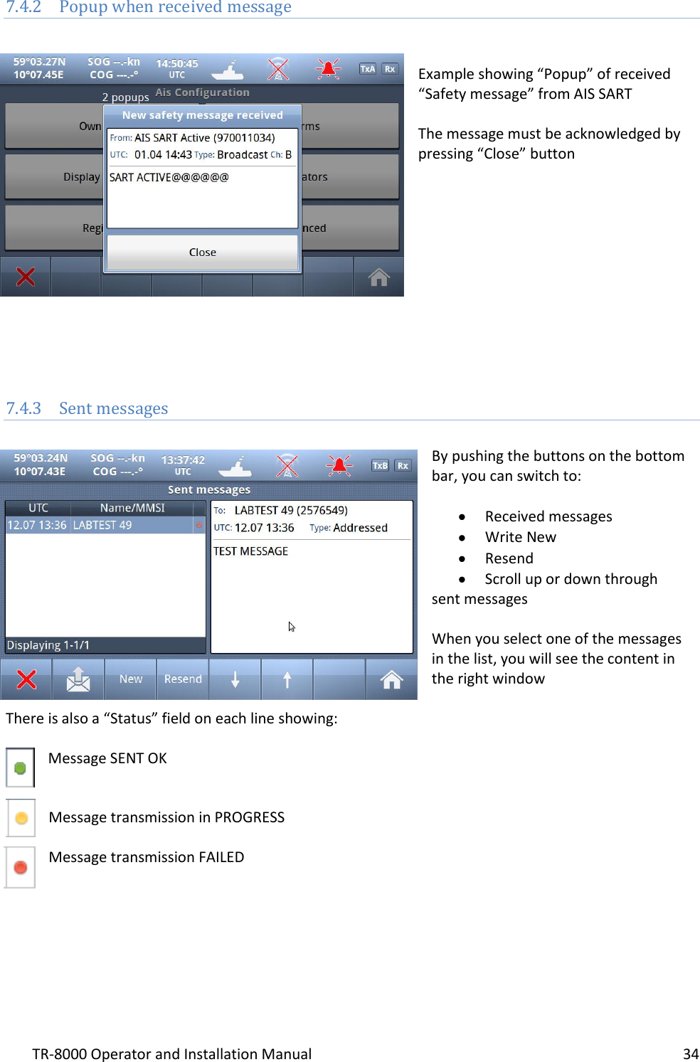
![TR-8000 Operator and Installation Manual 16 6.2.5 External Display (Ethernet) Connector RJ45 type waterproof Ethernet connection For more information see section 8.3.1.5 6.2.6 Multipurpose Cable Glands The Transponder Unit is fitted with up to 9 multipurpose cable glands for waterproof, shielded connection with the unit. There are 3 different sizes in order for the best possible fit for different cable types. All wiring should be drawn in shielded cables connected to the chassis of the Transponder by the cable glands. The multipurpose connection glands are provided as in . Max Quantity Min Cable Outer Ø [mm] Max Cable Outer Ø [mm] Minimum Ø above braiding [mm] Recommended use 3 3.5 7 2 Sensors 4 4.5 9 4 Communication 2 7 12.5 5 Power Table 1: Quantity and specification of multipurpose cable glands.](https://usermanual.wiki/Jotron-AS/TR8000.Operator-and-Installation-Manual-part-1/User-Guide-1790175-Page-16.png)


Operator and Installation Manual part1


![TR-8000 Operator and Installation Manual 16 6.2.5 External Display (Ethernet) Connector RJ45 type waterproof Ethernet connection For more information see section 8.3.1.5 6.2.6 Multipurpose Cable Glands The Transponder Unit is fitted with up to 9 multipurpose cable glands for waterproof, shielded connection with the unit. There are 3 different sizes in order for the best possible fit for different cable types. All wiring should be drawn in shielded cables connected to the chassis of the Transponder by the cable glands. The multipurpose connection glands are provided as in . Max Quantity Min Cable Outer Ø [mm] Max Cable Outer Ø [mm] Minimum Ø above braiding [mm] Recommended use 3 3.5 7 2 Sensors 4 4.5 9 4 Communication 2 7 12.5 5 Power Table 1: Quantity and specification of multipurpose cable glands.](https://usermanual.wiki/Jotron-AS/TR8000.Operator-and-Installation-Manual-part1/User-Guide-1790178-Page-16.png)