Jotron AS TR8000 Tron AIS TR-8000 User Manual Operator and Installation Manual part 3
Jotron AS Tron AIS TR-8000 Operator and Installation Manual part 3
Contents
- 1. Technical Manual
- 2. Operator and Installation Manual part 1
- 3. Operator and Installation Manual part1
- 4. Operator and Installation Manual part 2
- 5. Operator and Installation Manual part 3
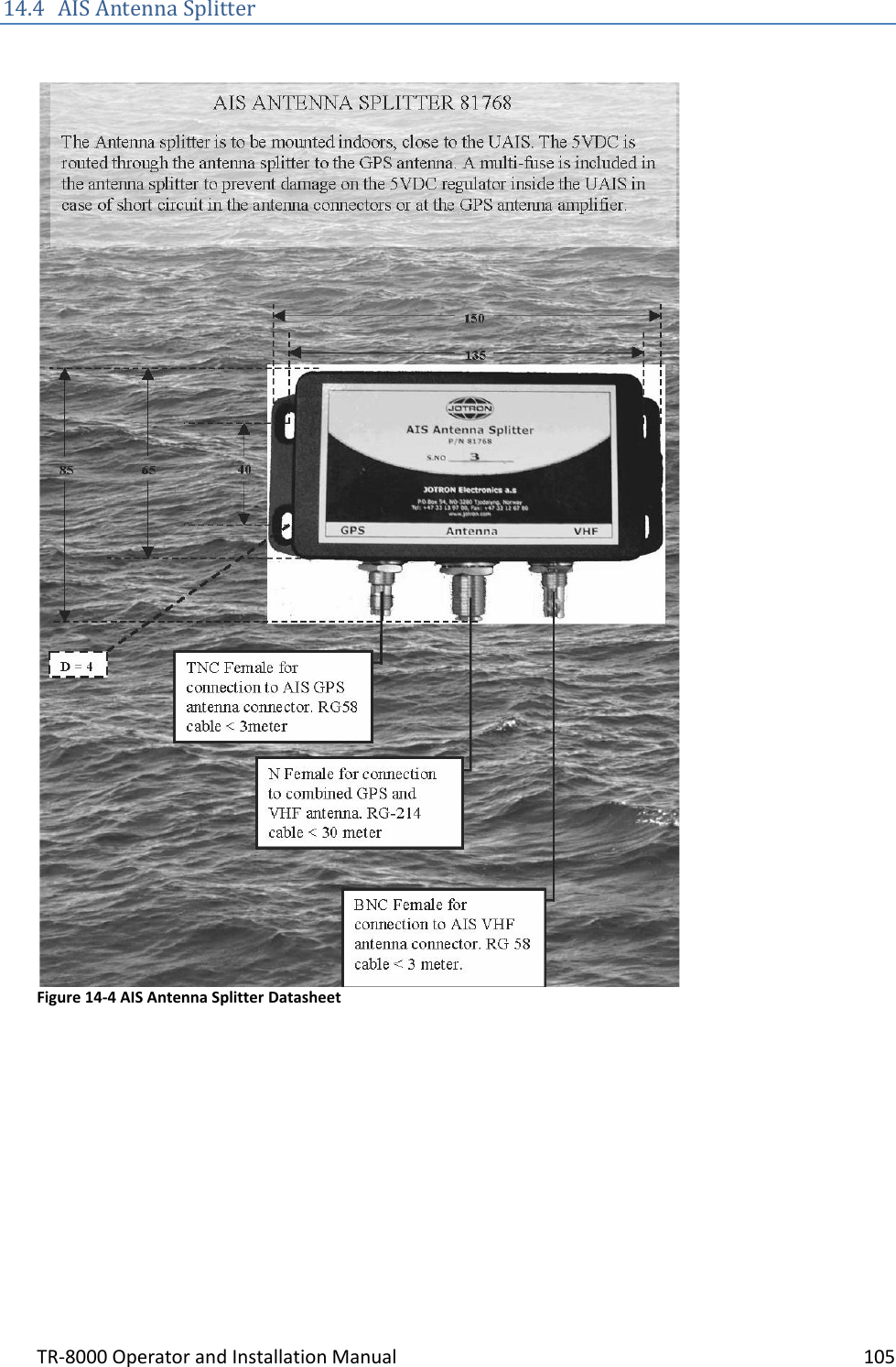
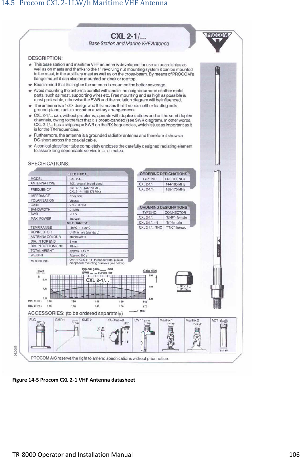
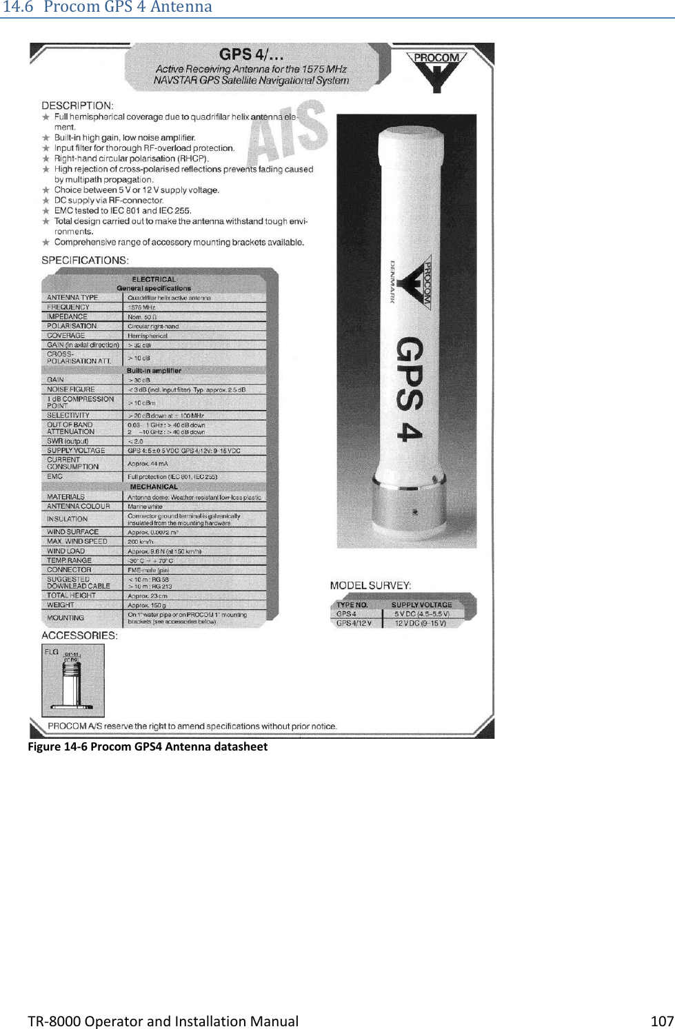
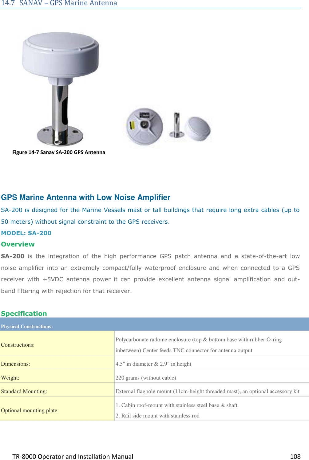
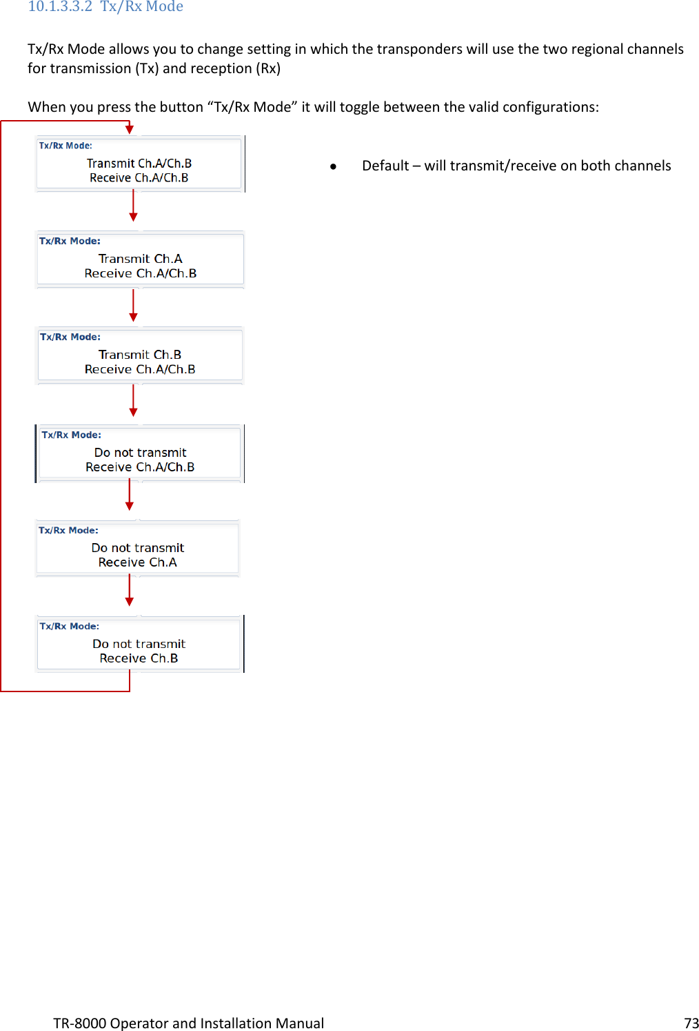
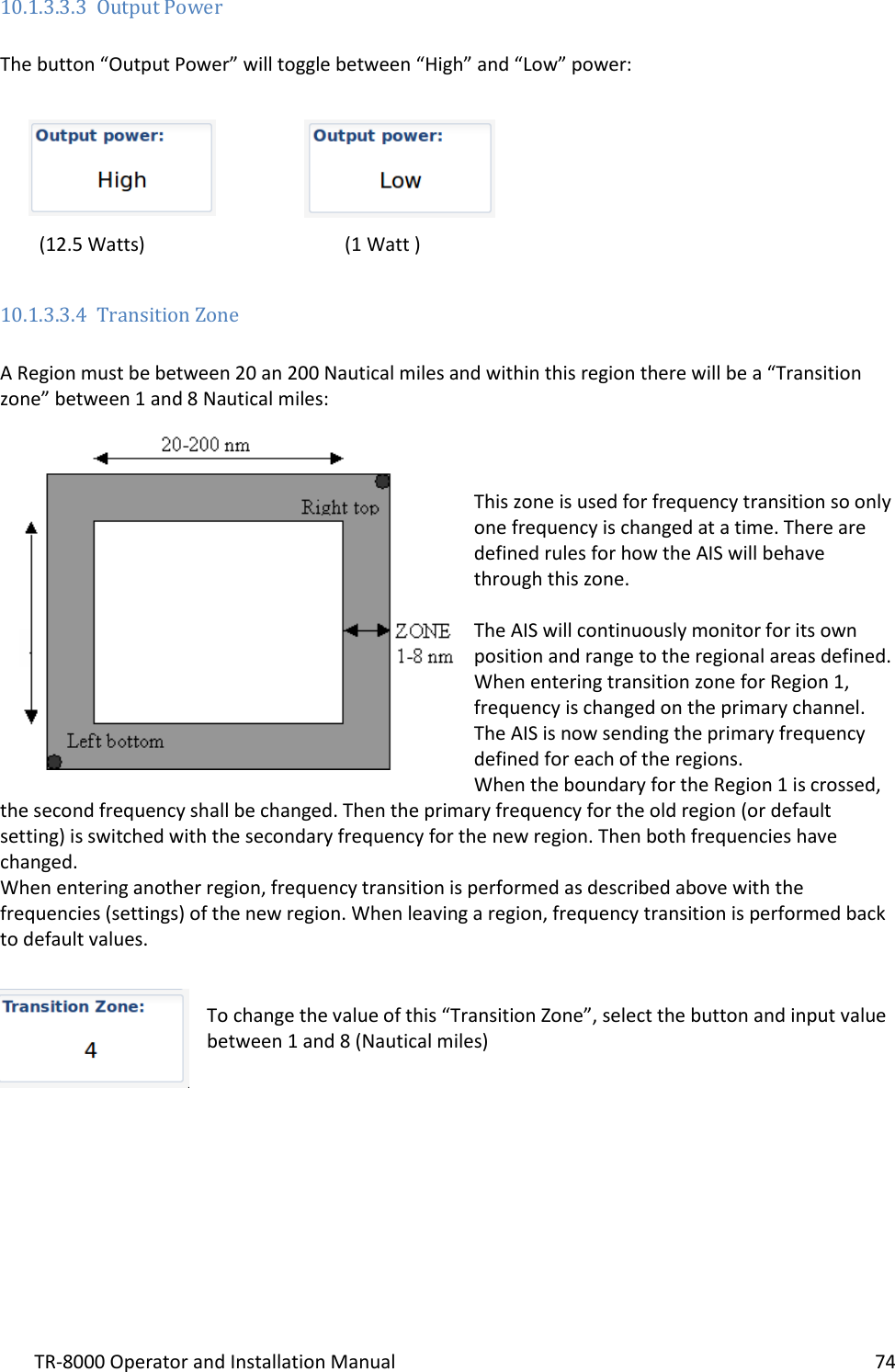
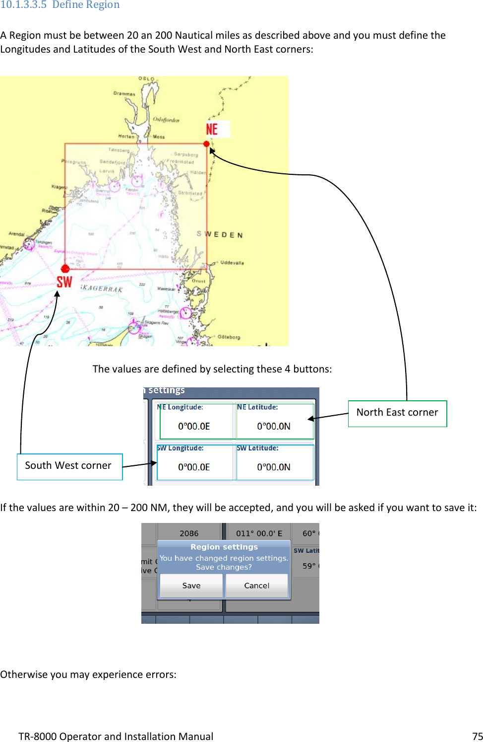
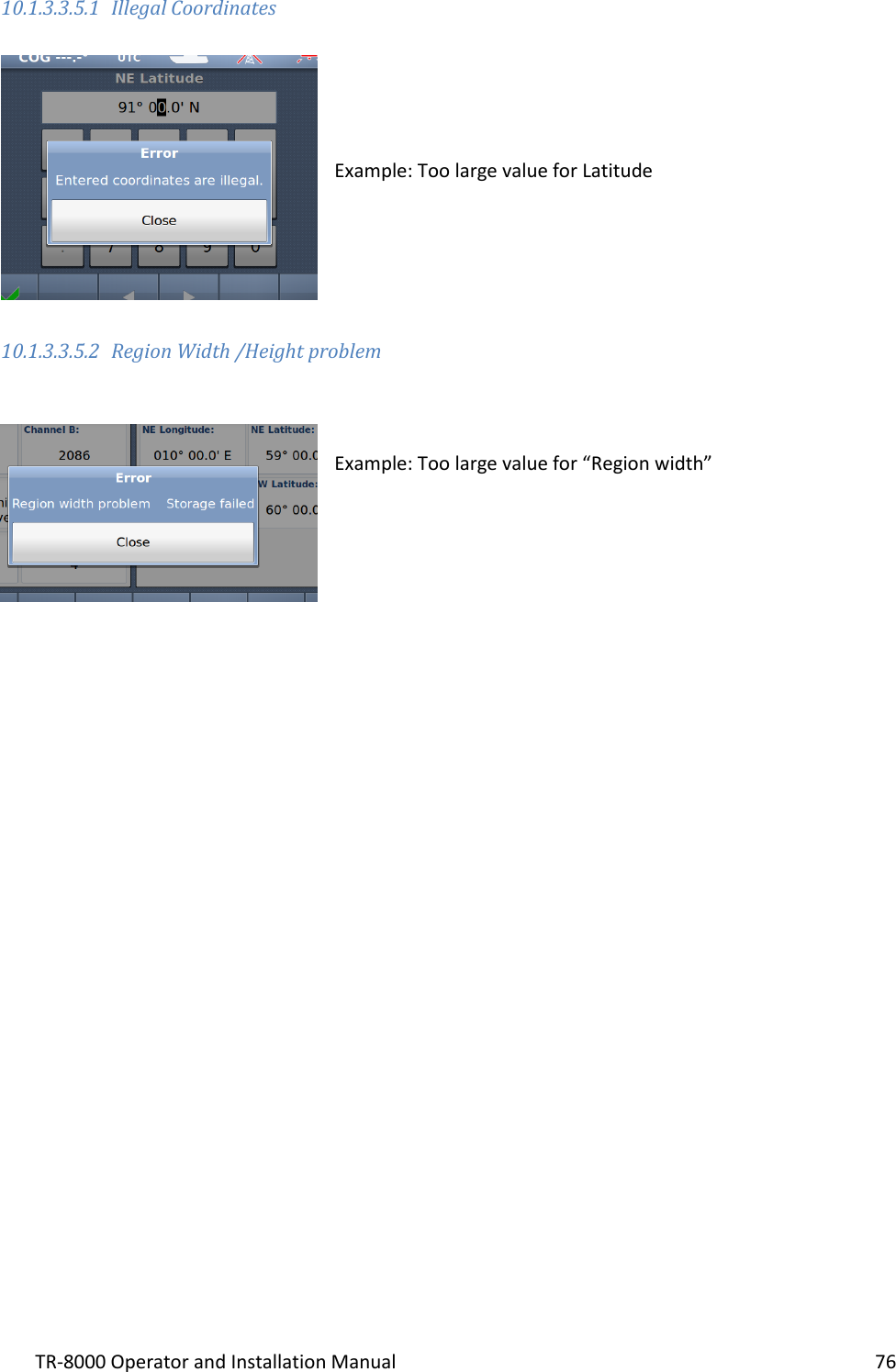
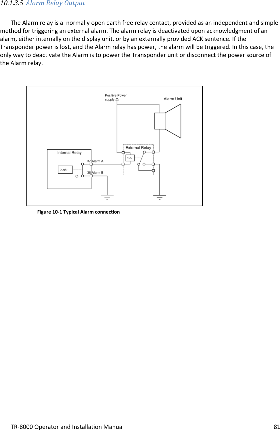
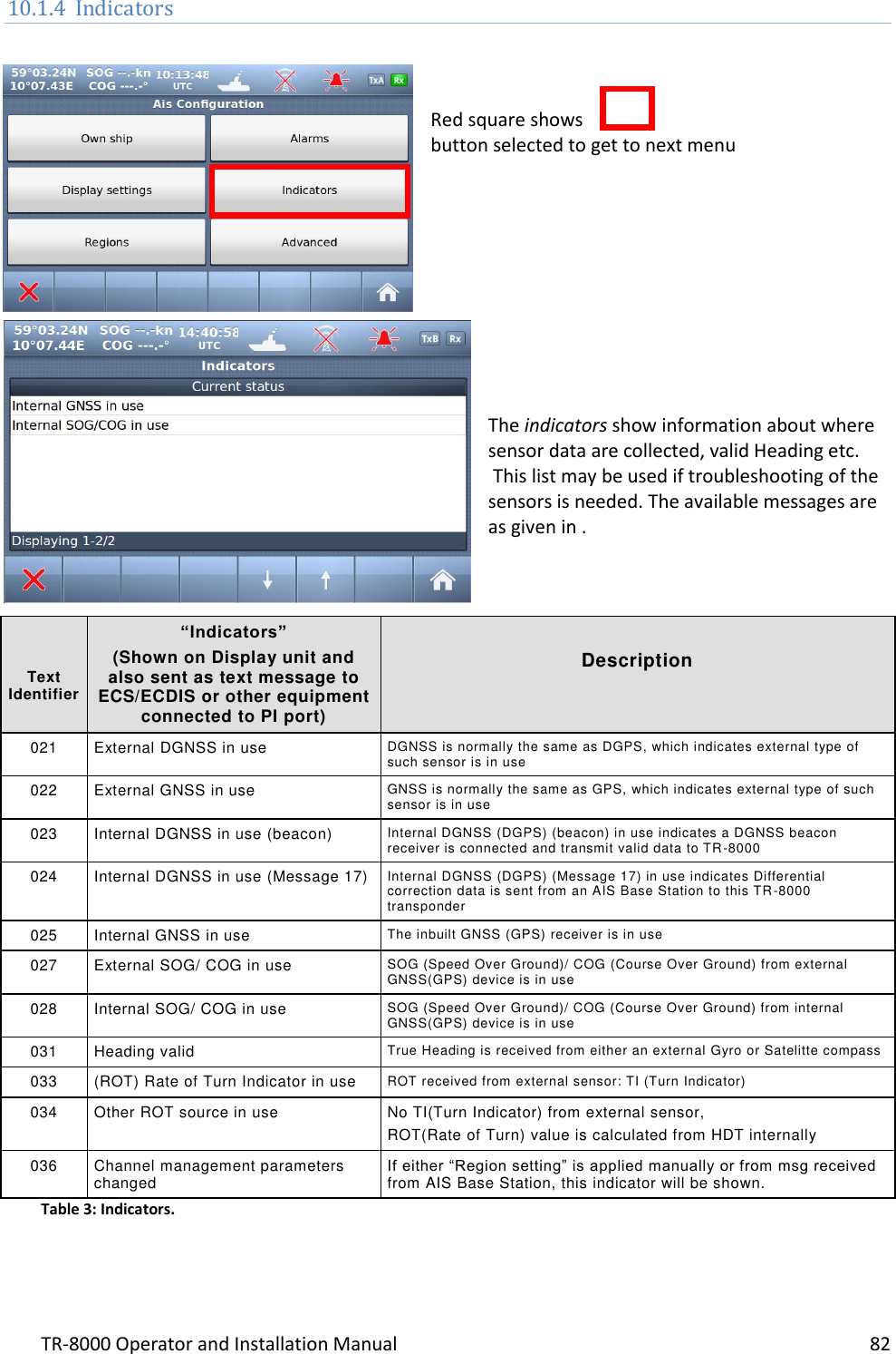
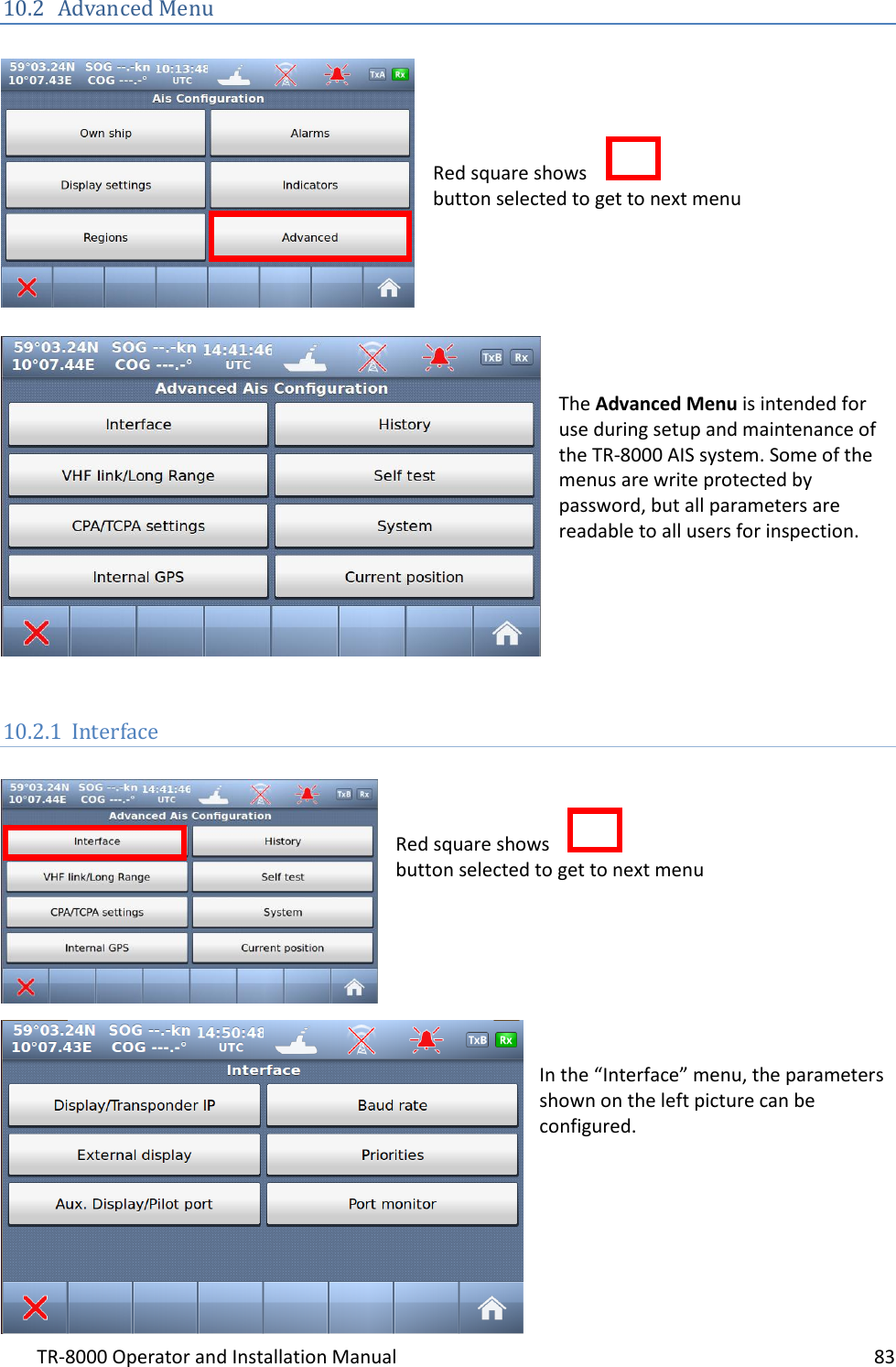
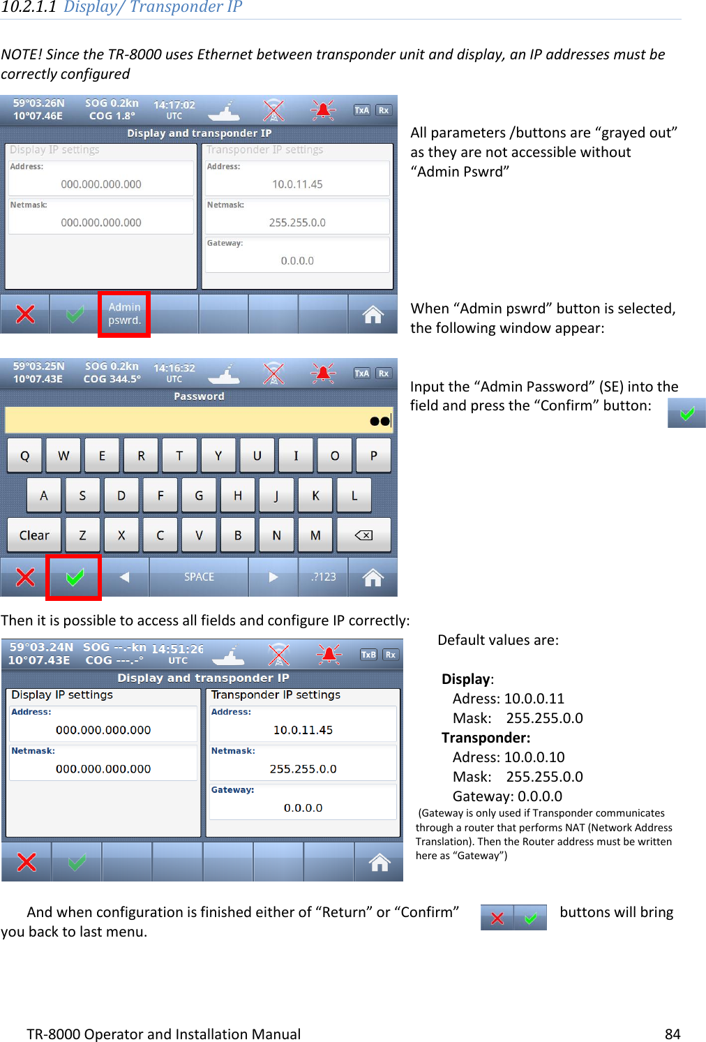
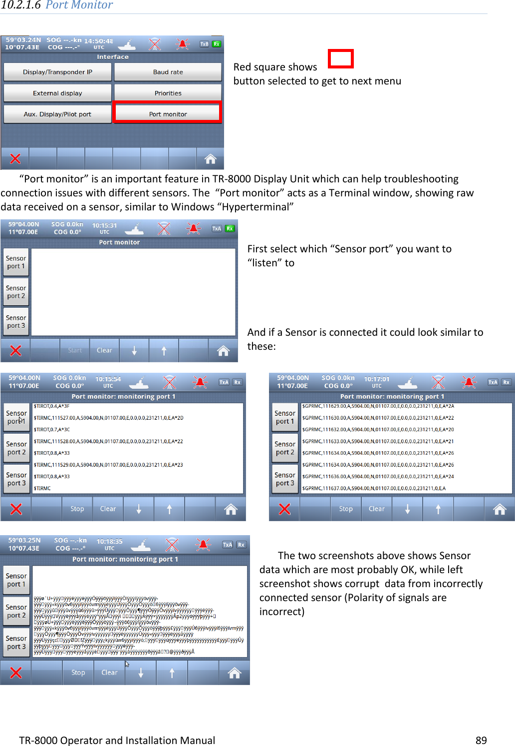
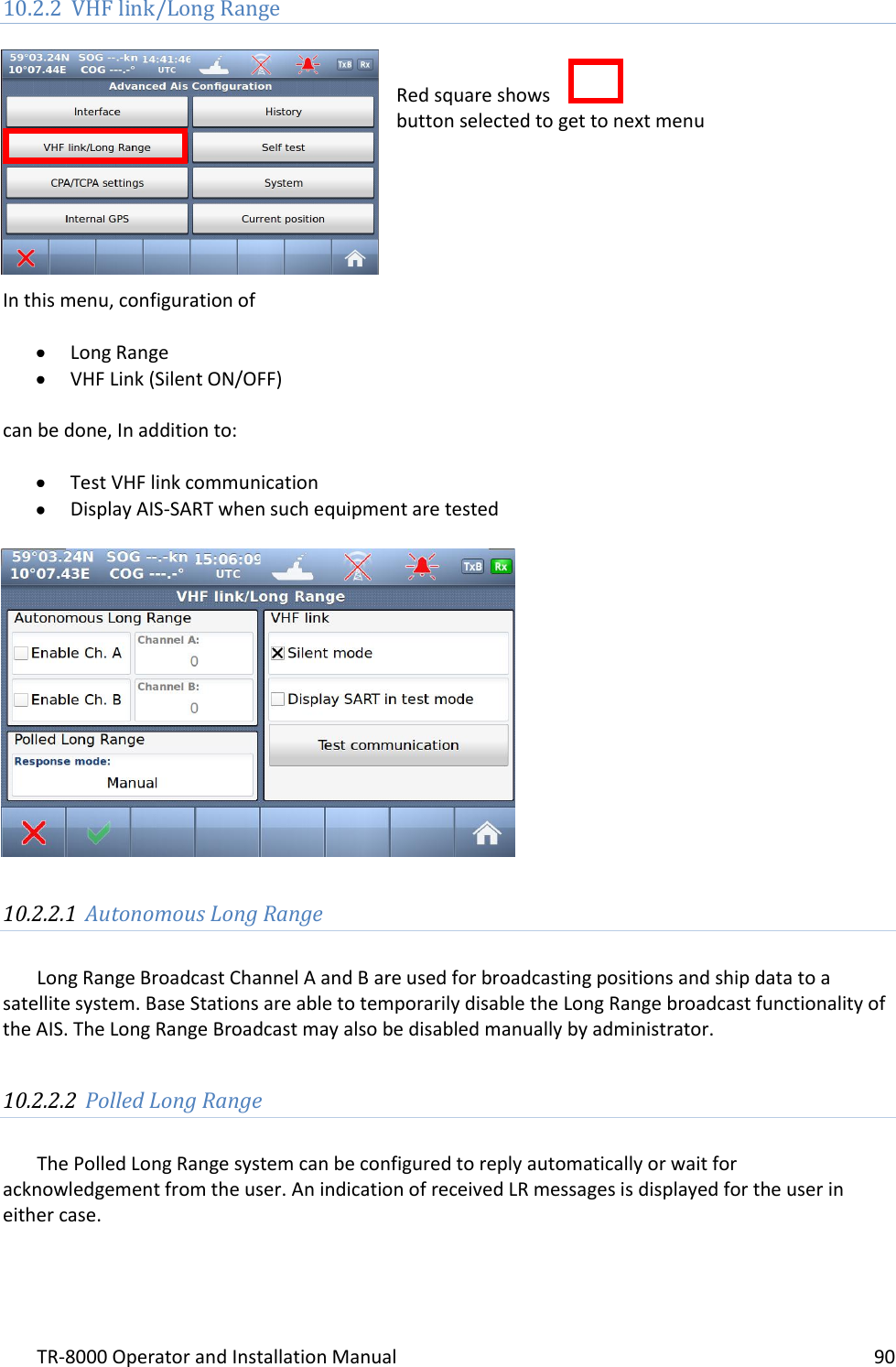
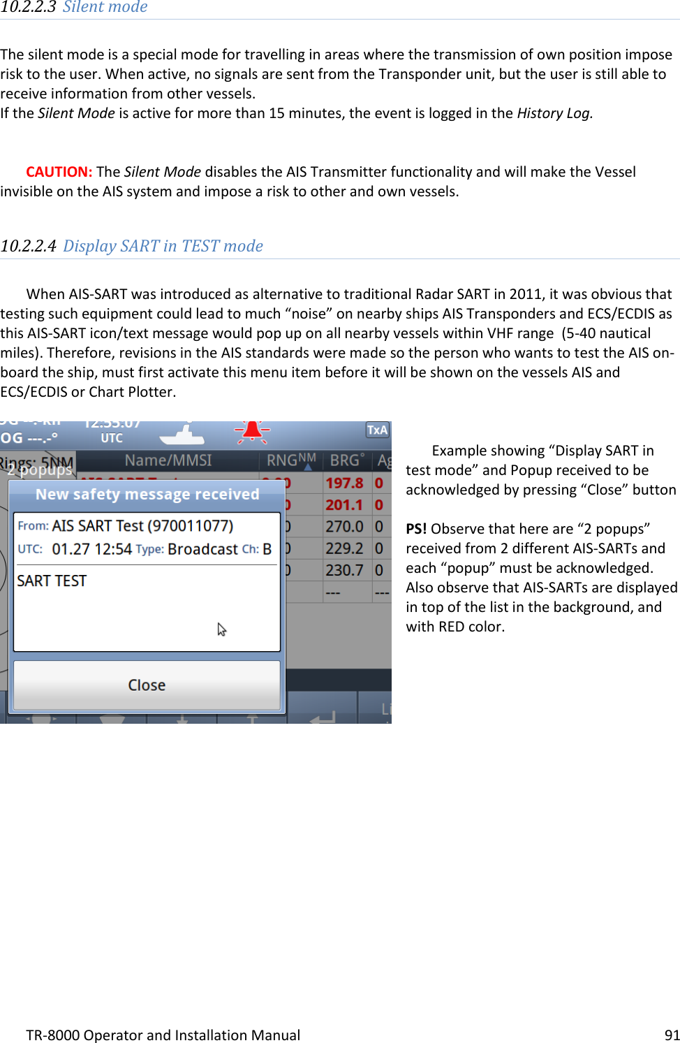
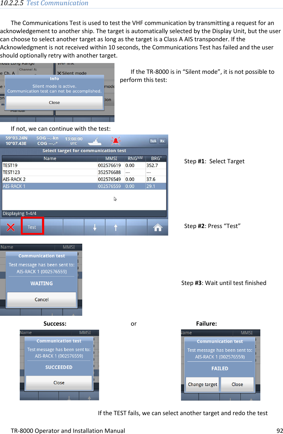
Operator and Installation Manual part 3
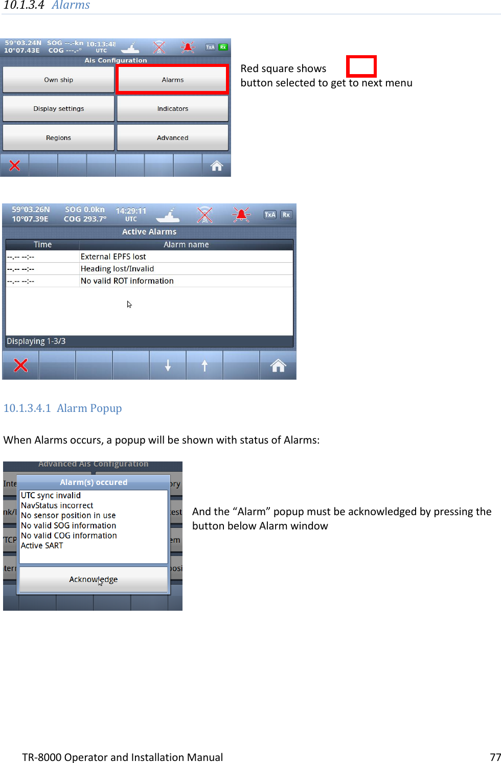
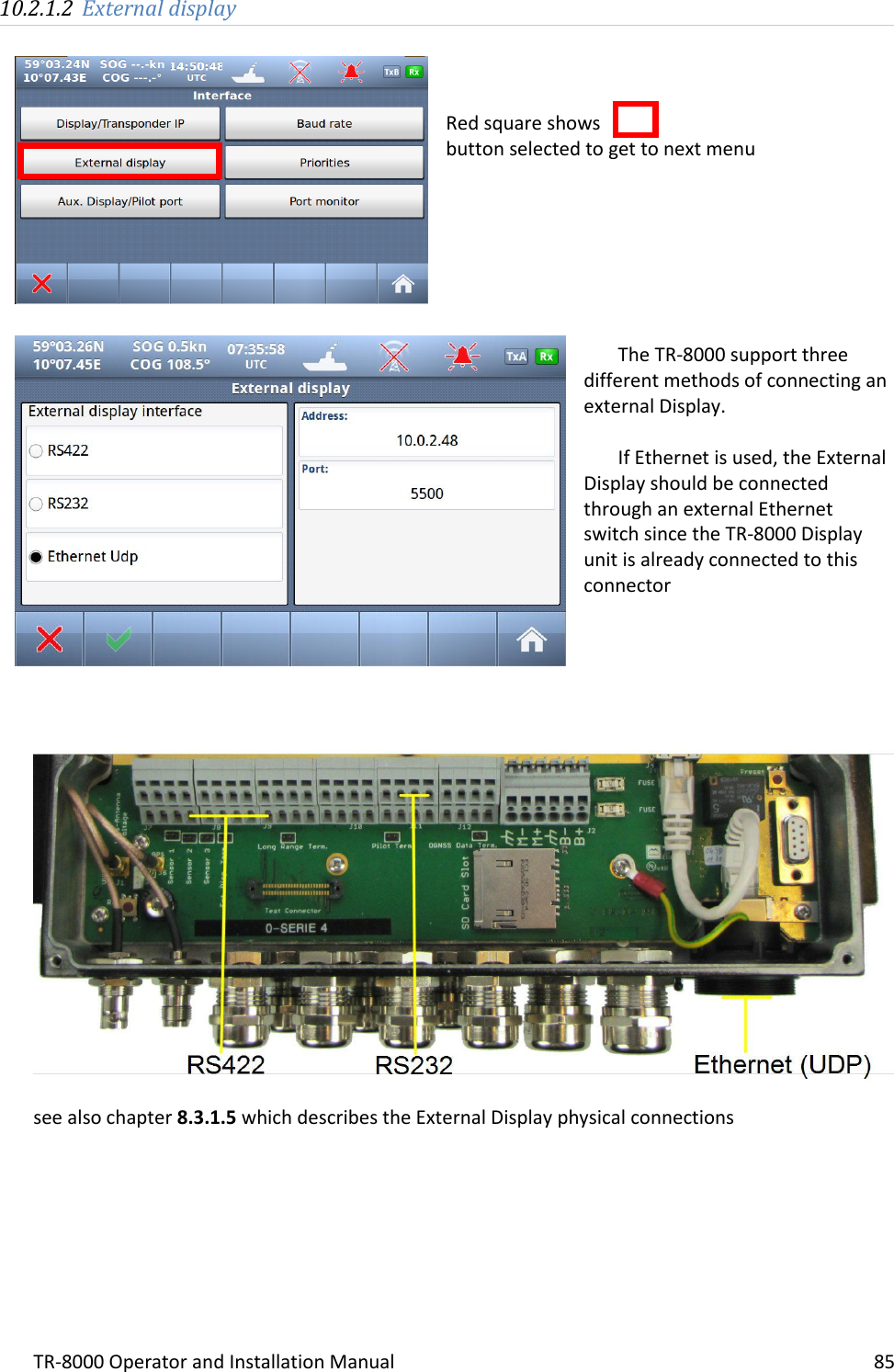
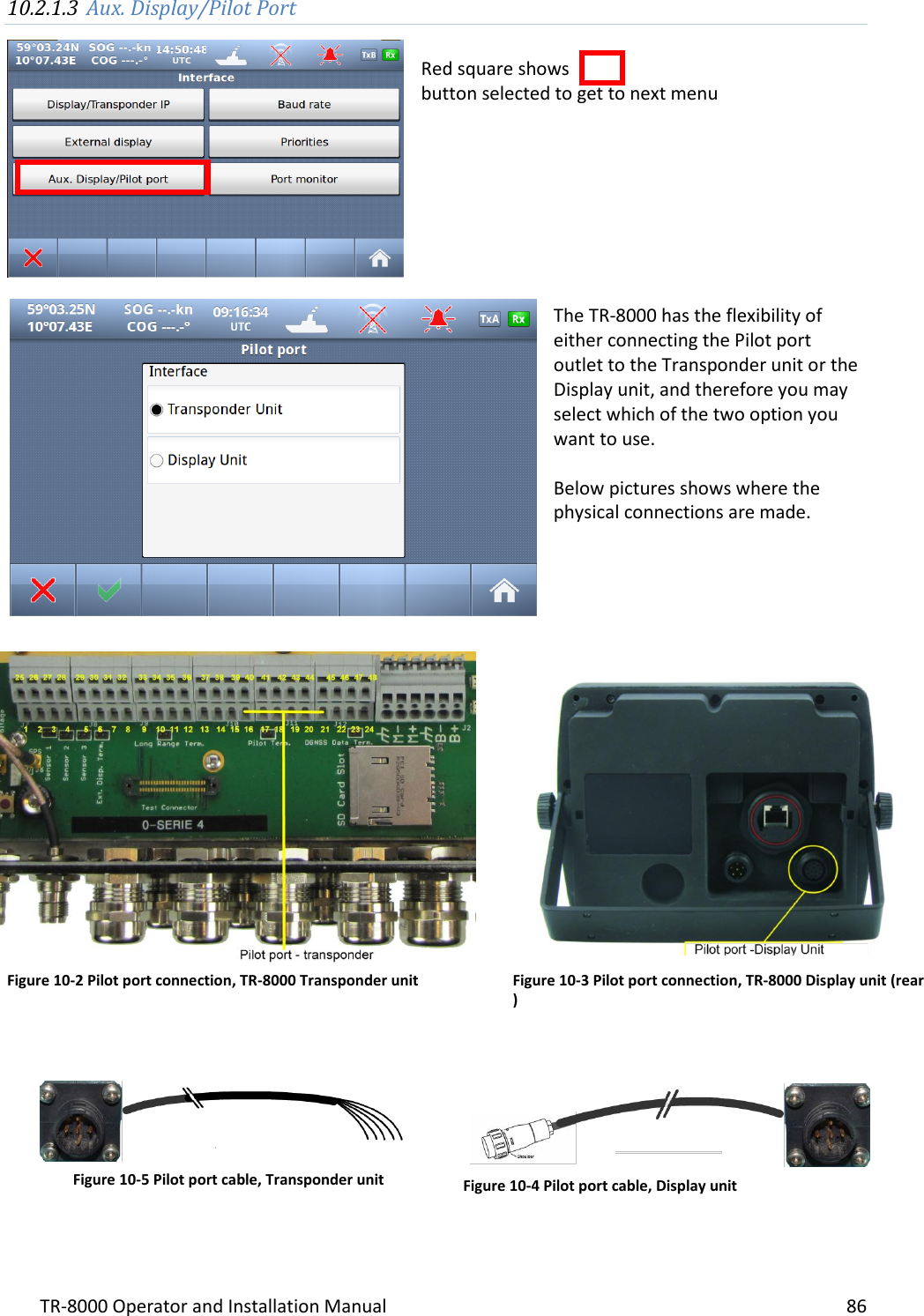
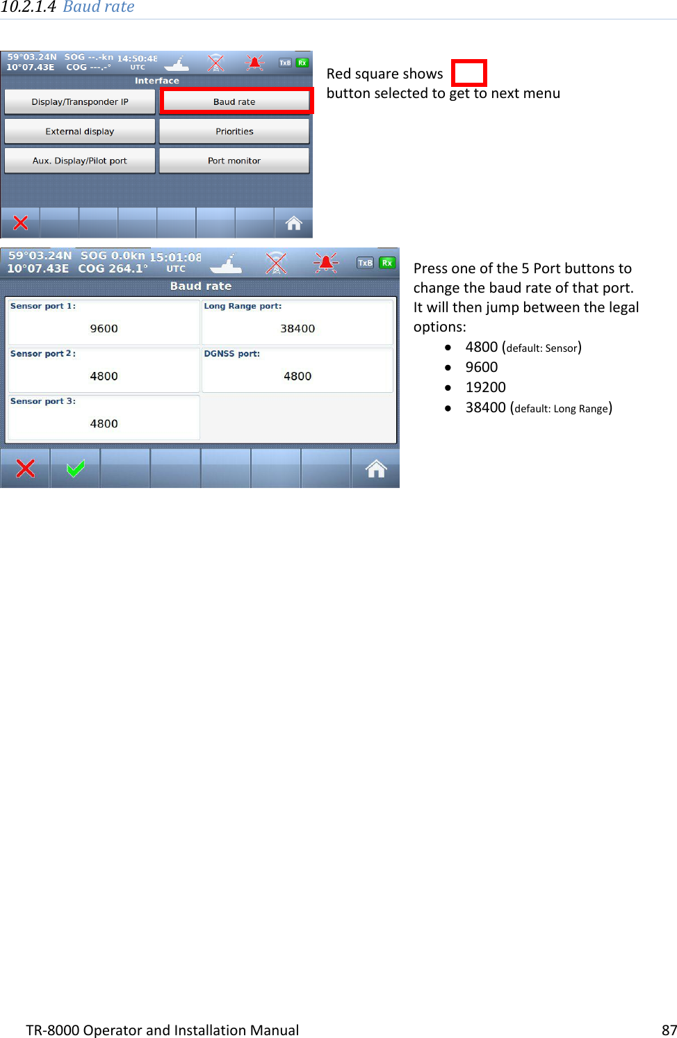
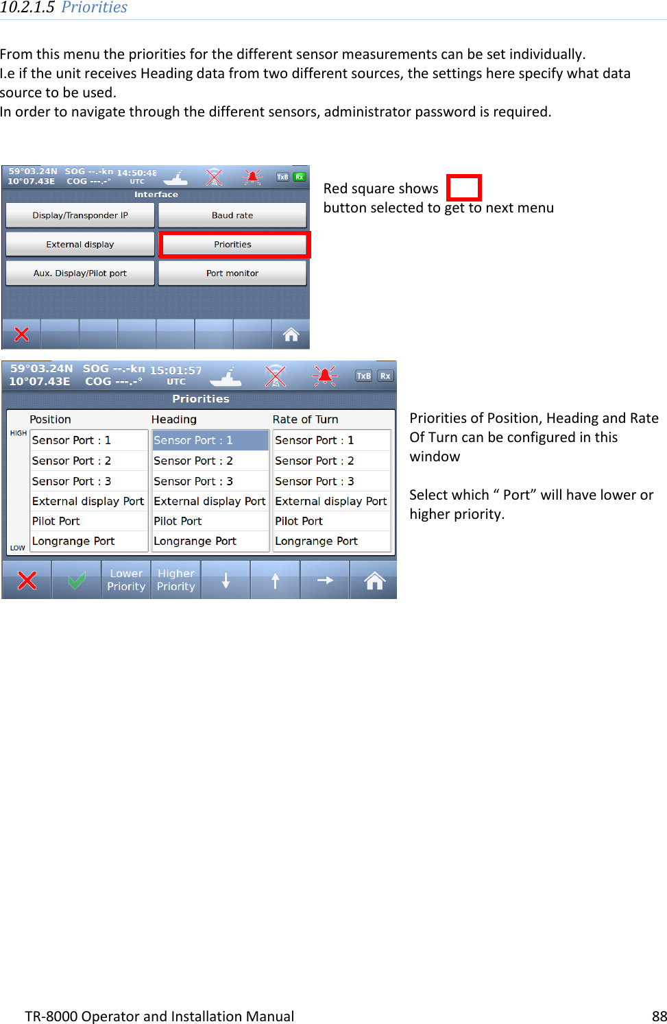
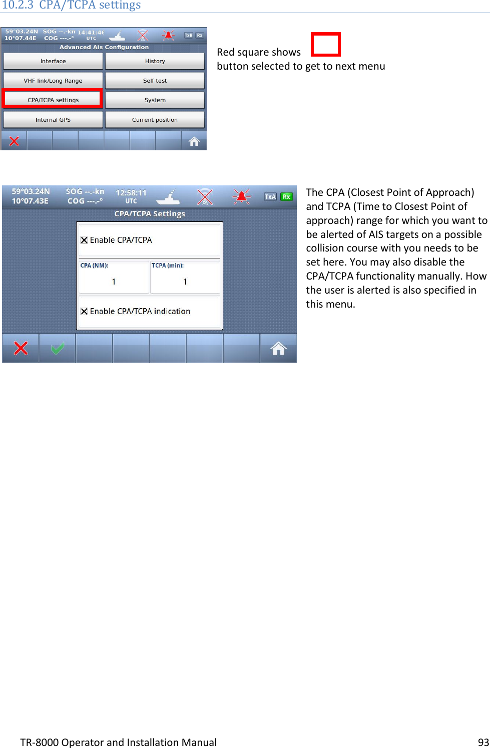
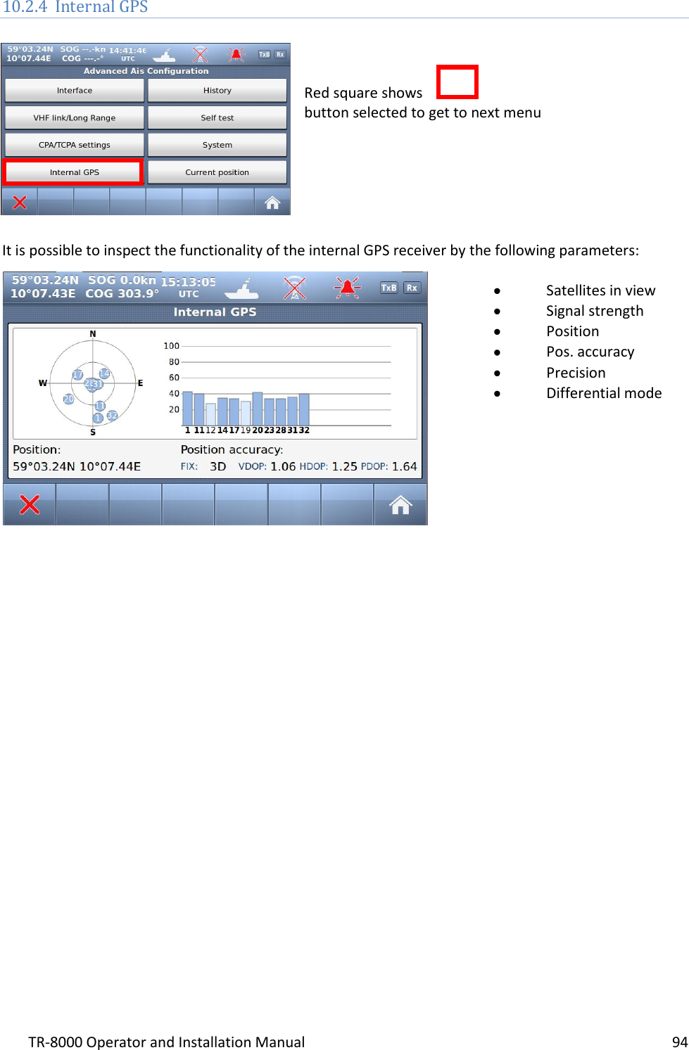
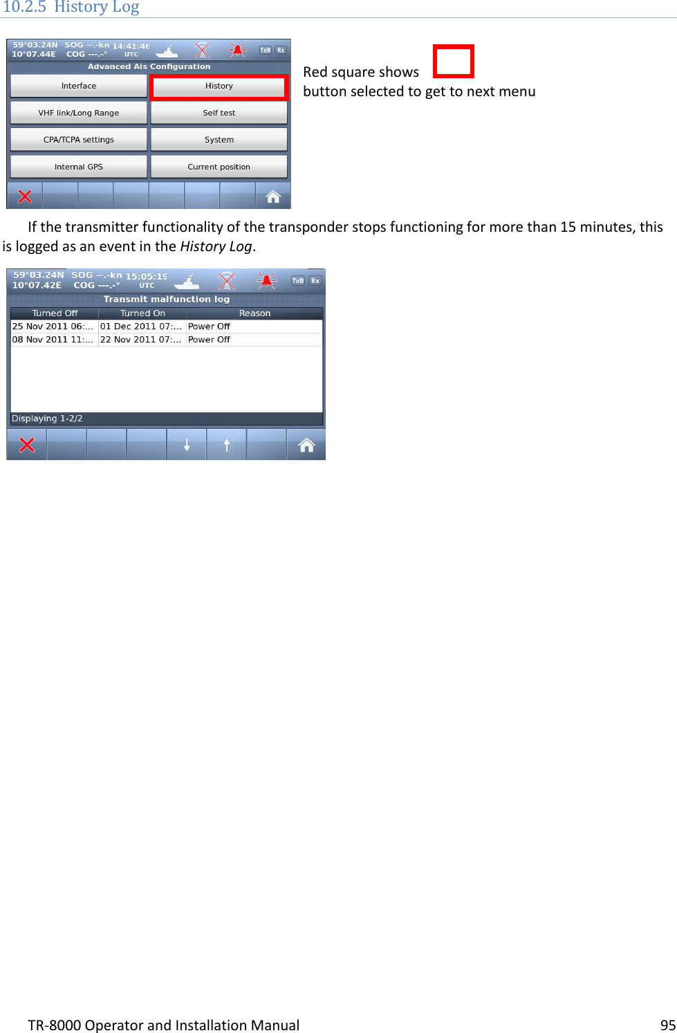
![TR-8000 Operator and Installation Manual 96 10.2.6 Self Test Red square shows button selected to get to next menu The “Self Test” consist of two different tests, a “Transponder self test” and a “Display self test”: “Transponder self test” measures values of: Signal strength (RSSI.. 0-255) RF Power (Forward+ Reflected :0-512) Antenna matching (VSWR) Voltages ( 3, 5, 8 and 14v) Receivers status Transmitter status Power source (Main, Backup) When “Display test” is selected, this window is shown with measurement: Voltages Supply source (Power source) Light sensor reading (If automatic display adjustment are activated [option])](https://usermanual.wiki/Jotron-AS/TR8000.Operator-and-Installation-Manual-part-3/User-Guide-1790183-Page-26.png)