Jotron AS TR8000 Tron AIS TR-8000 User Manual Operator and Installation Manual part 2
Jotron AS Tron AIS TR-8000 Operator and Installation Manual part 2
Contents
- 1. Technical Manual
- 2. Operator and Installation Manual part 1
- 3. Operator and Installation Manual part1
- 4. Operator and Installation Manual part 2
- 5. Operator and Installation Manual part 3
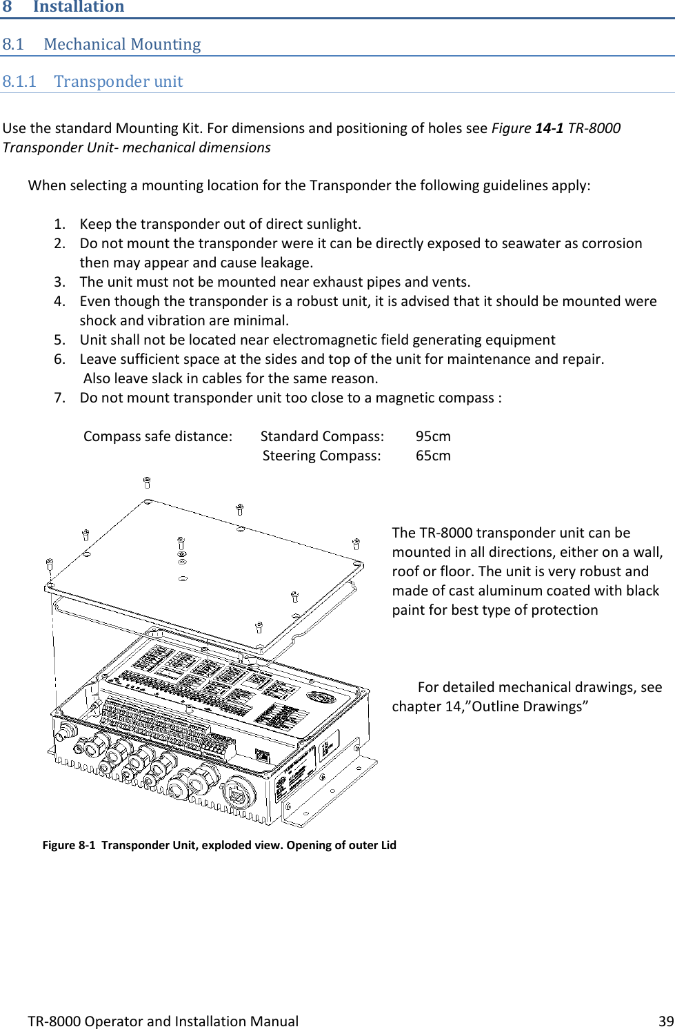
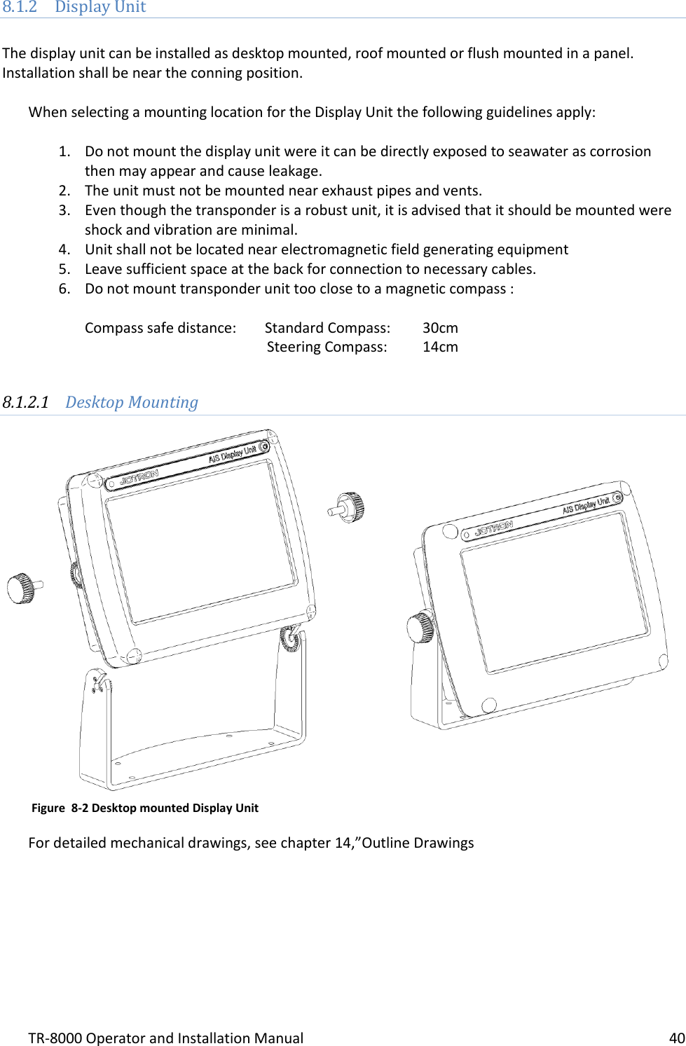
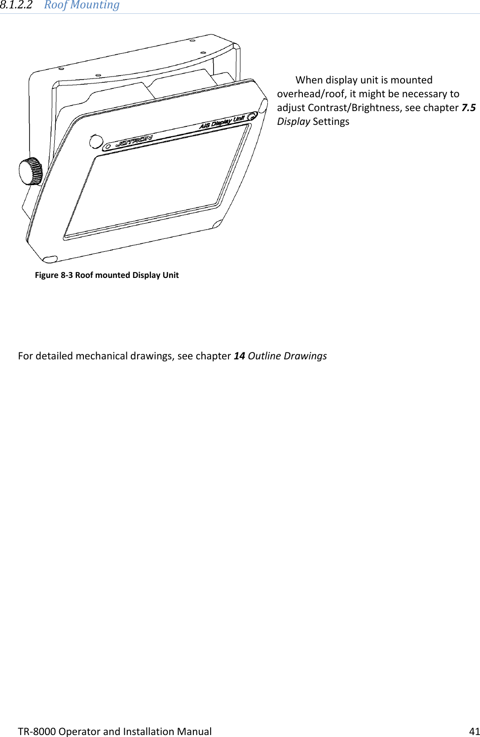
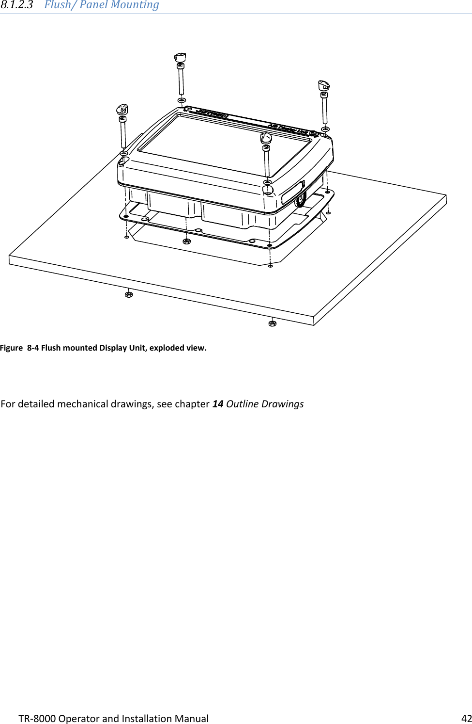
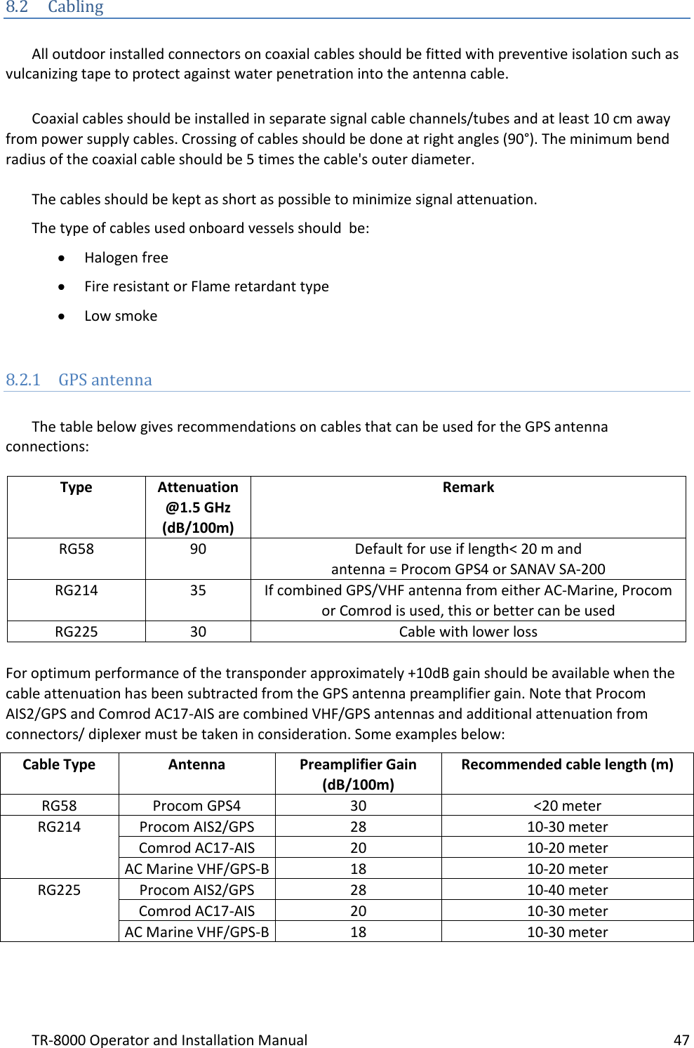
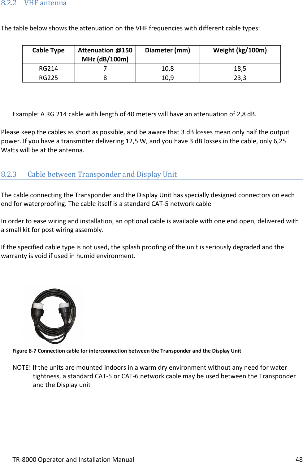
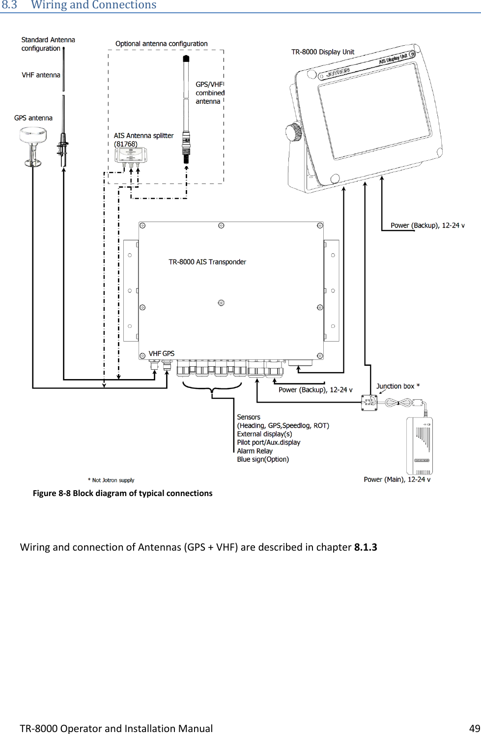
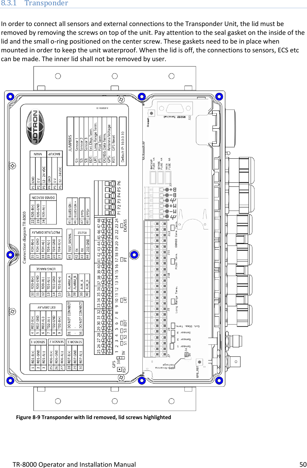
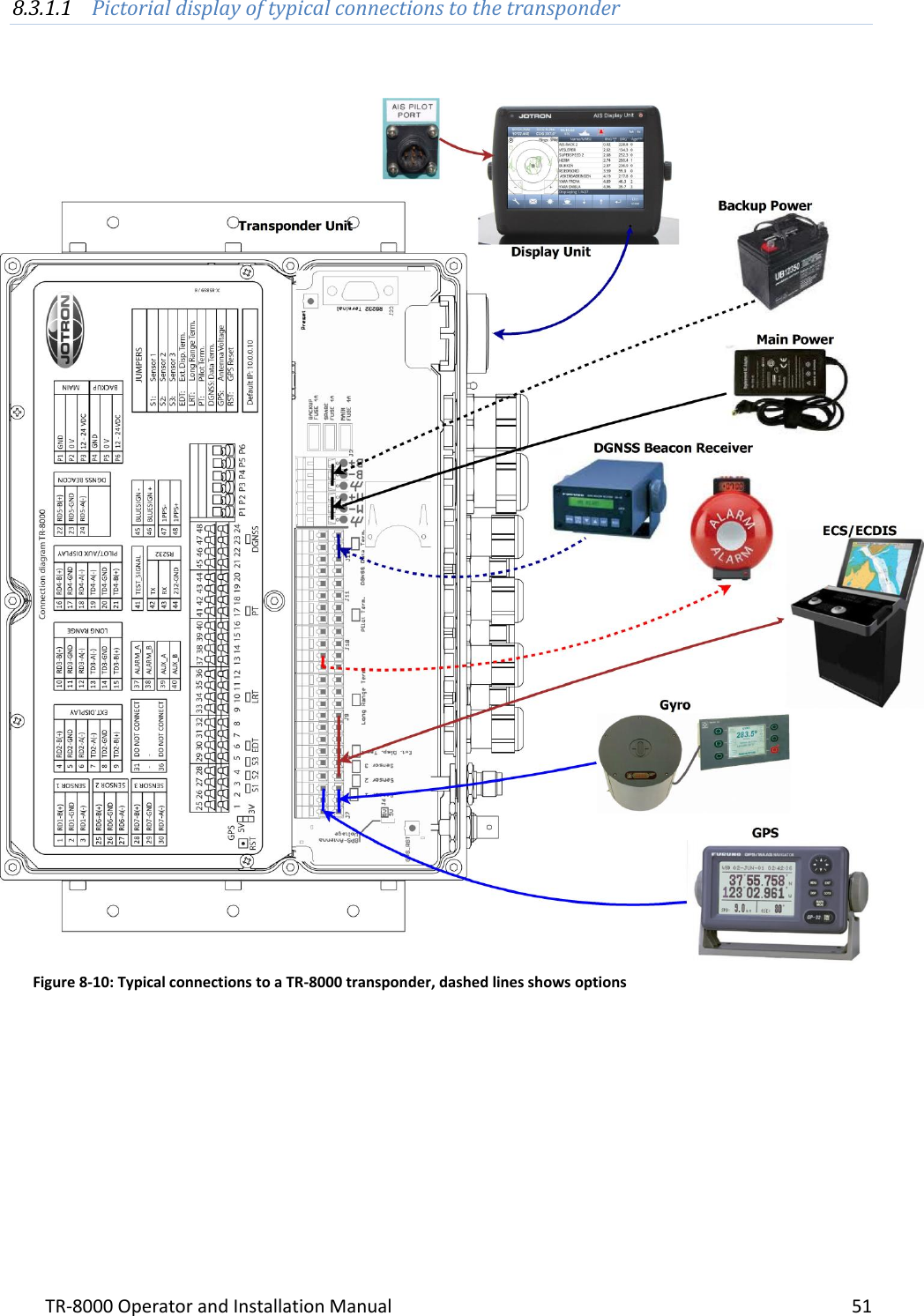
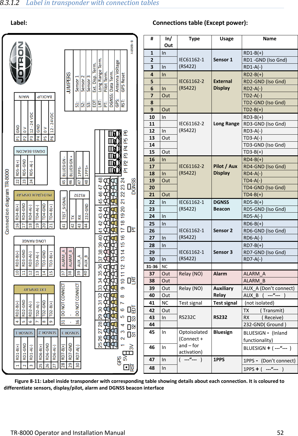
Operator and Installation Manual part 2