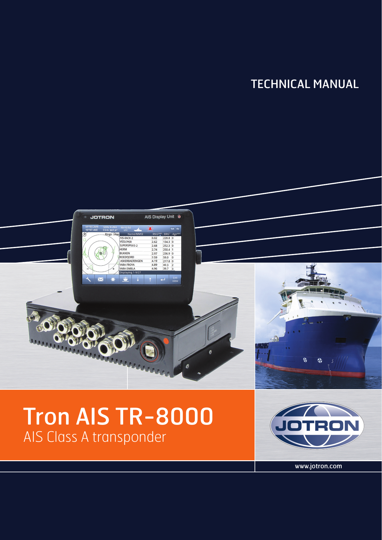
Jotron AS TR8000 Tron AIS TR-8000 User Manual Technical Manual
Jotron AS Tron AIS TR-8000 Technical Manual
UserManual.wiki
>
Jotron AS
>
TR8000 User Manual
>
Technical Manual
Contents
1.
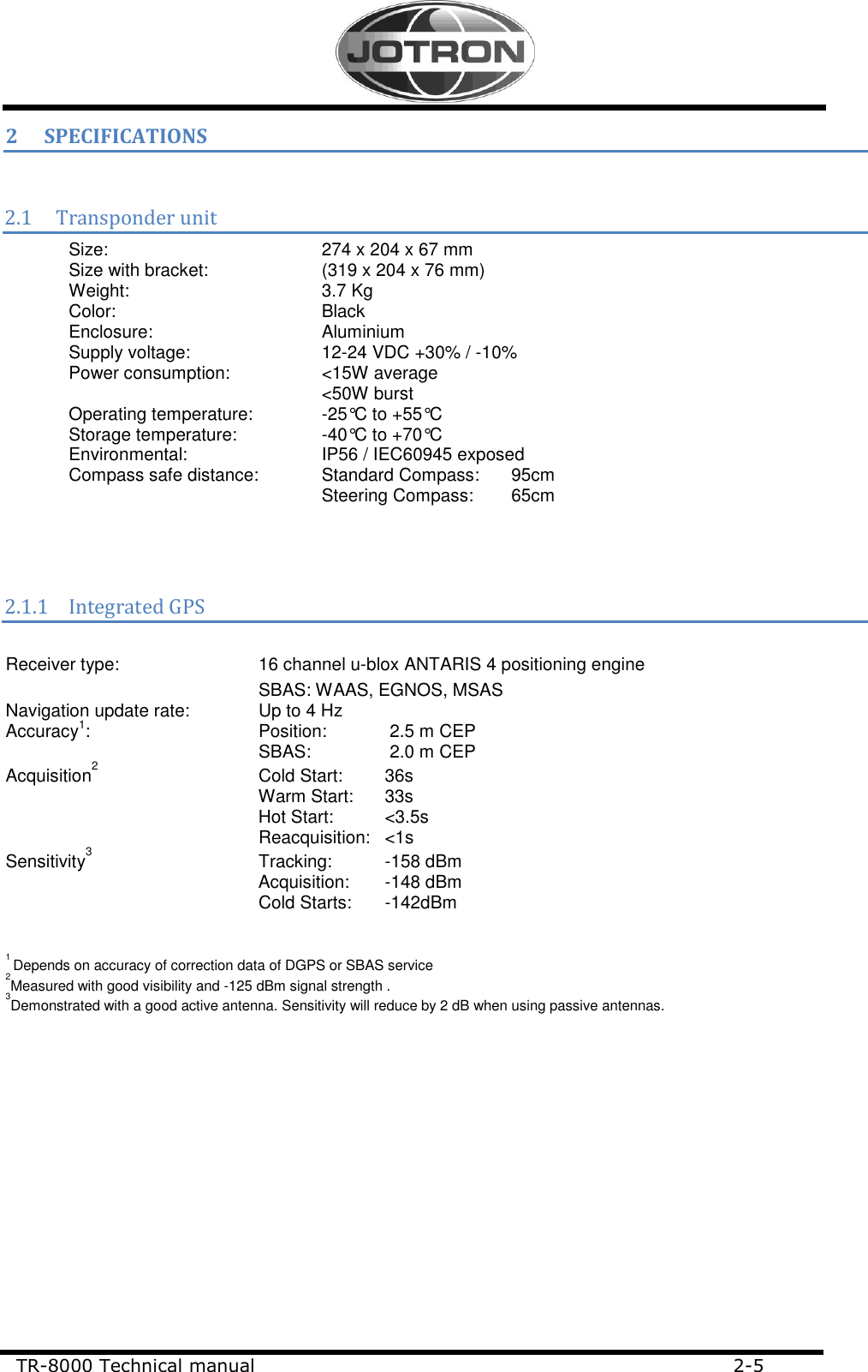
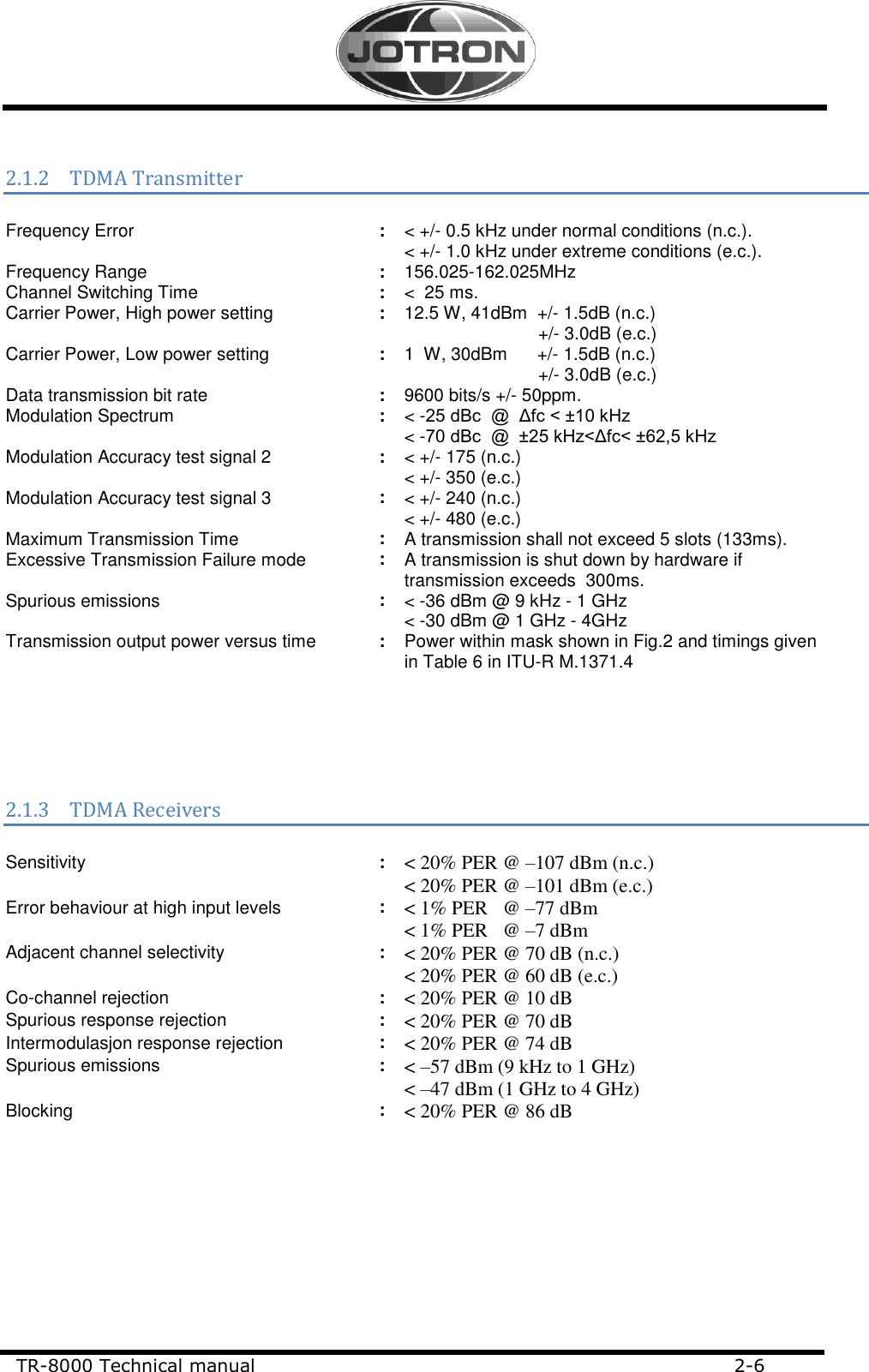
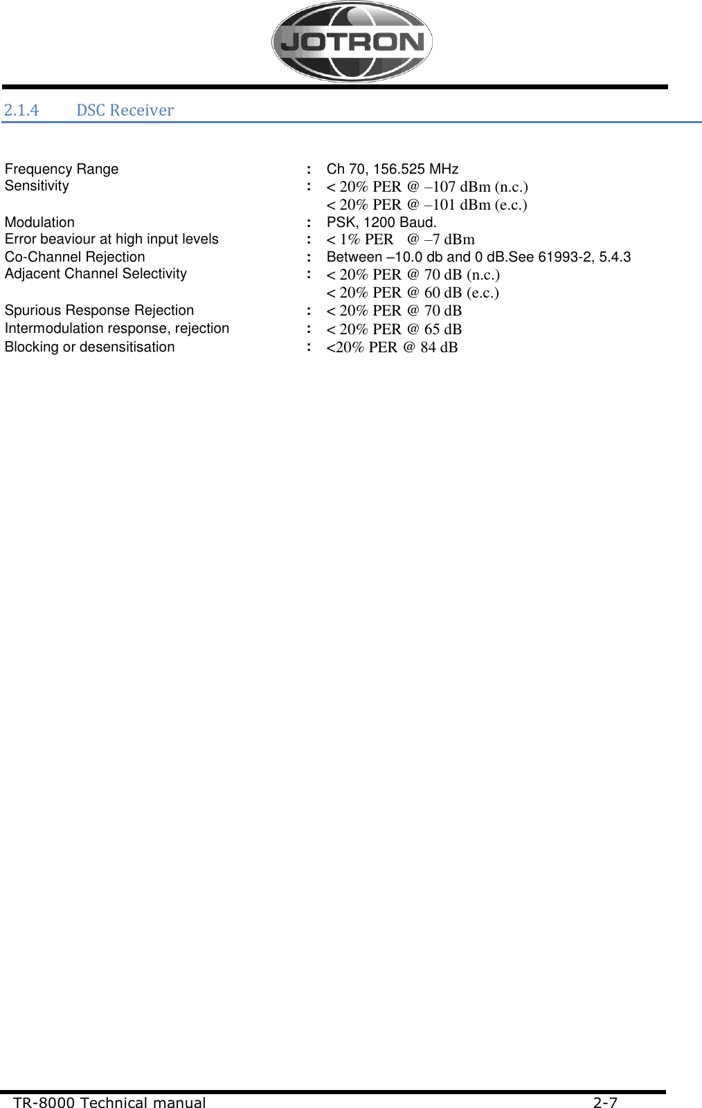
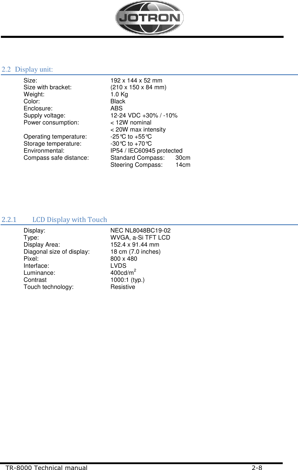
Technical Manual
2.
Operator and Installation Manual part 1
3.
Operator and Installation Manual part1
4.
Operator and Installation Manual part 2
5.
Operator and Installation Manual part 3
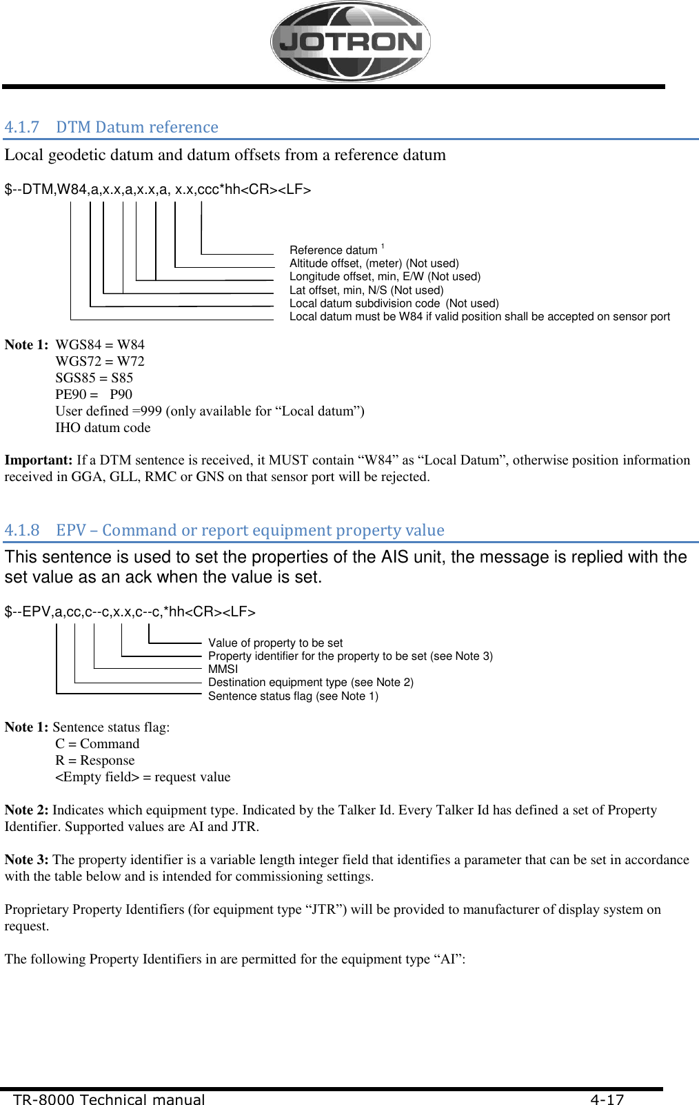
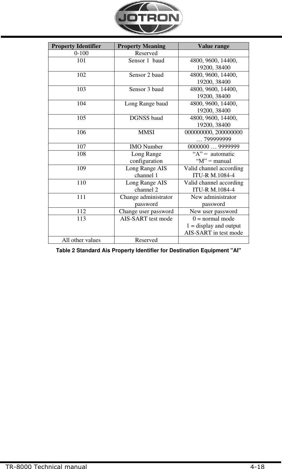
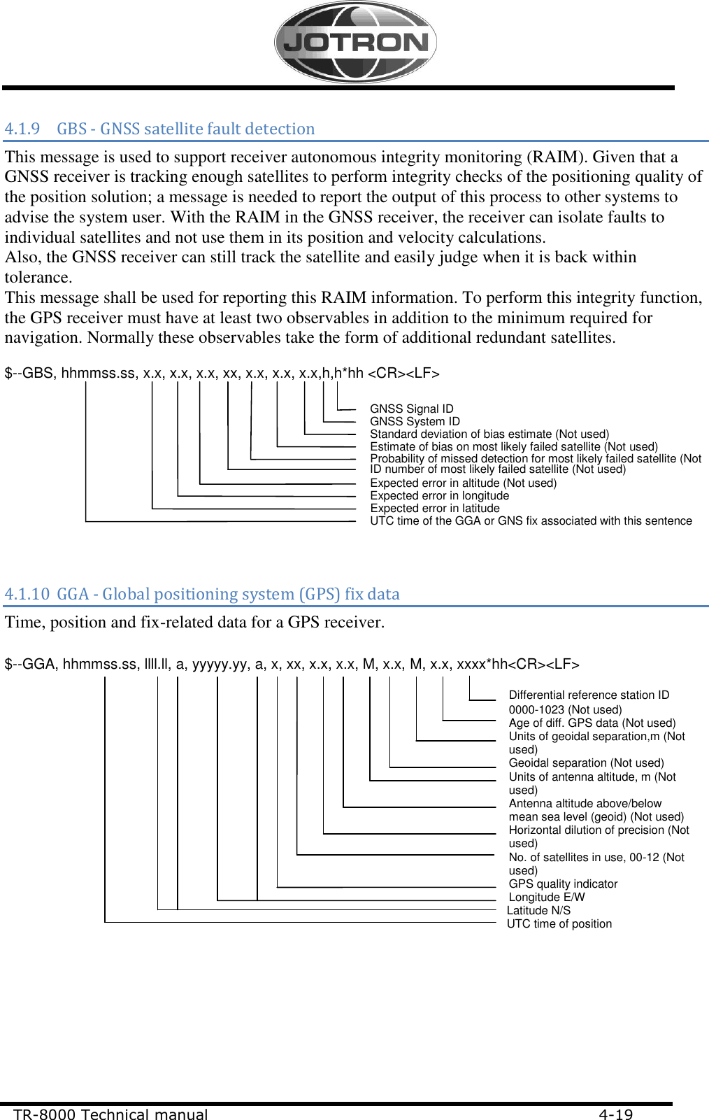
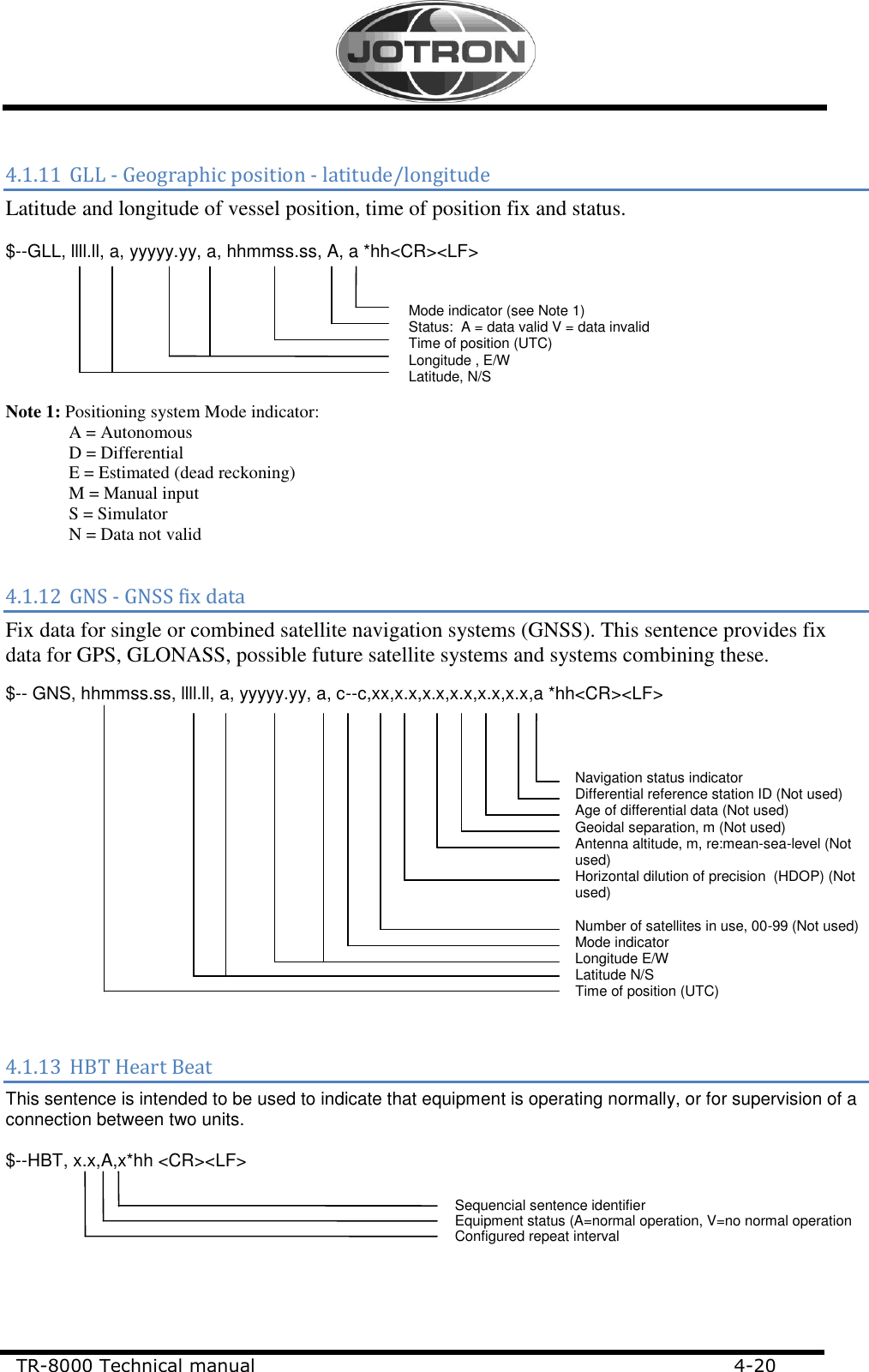
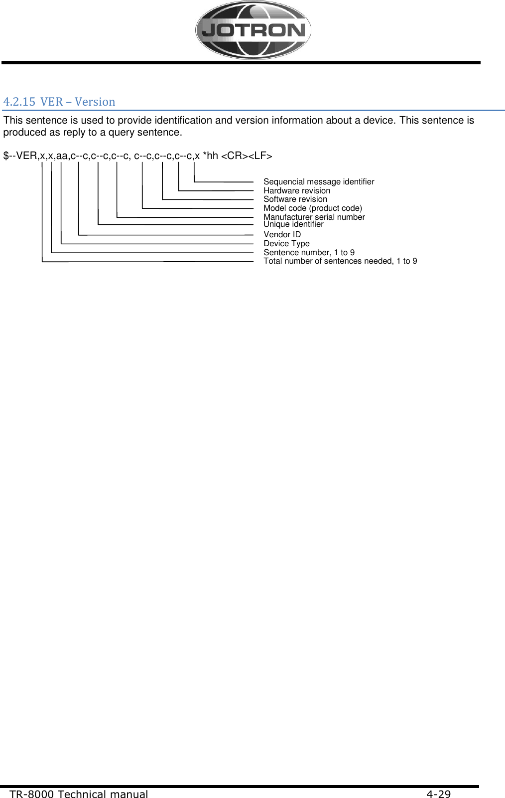
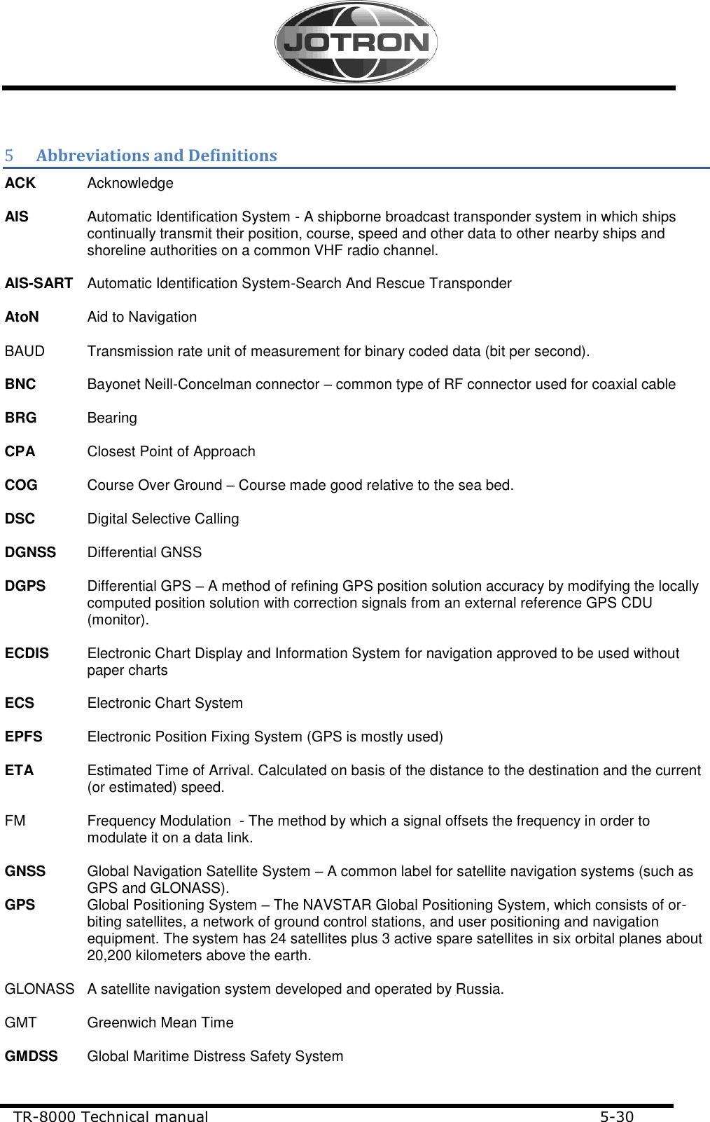
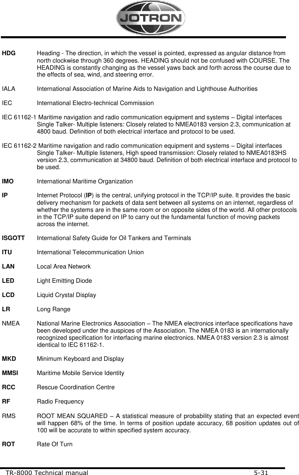
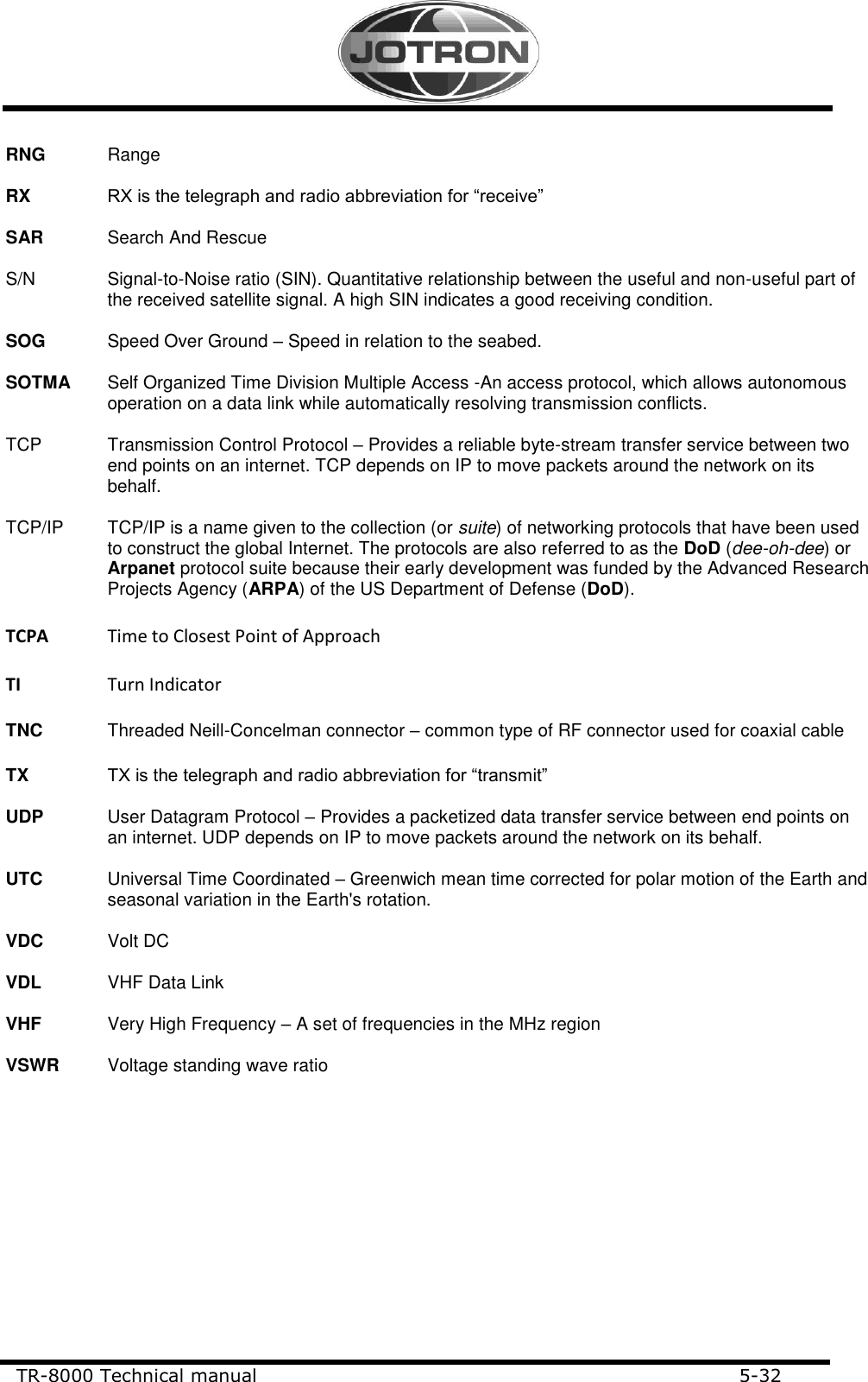
Technical Manual
Navigation menu
Upload a User Manual
Namespaces
Wiki Guide
HTML
PDF
Info
Views
User Manual
Discussion / Help
Navigation