Jotron AS TR8000 Tron AIS TR-8000 User Manual Technical Manual
Jotron AS Tron AIS TR-8000 Technical Manual
Contents
Technical Manual

www.jotron.com
TECHNICAL MANUAL
Tron AIS TR-8000
AIS Class A transponder

TR-8000 Technical manual 1-2
EC Declaration of Conformity, available at www.jotron.com
Table of Contents
1 Revision History.................................................................................................................... 1-4
2 SPECIFICATIONS ................................................................................................................... 2-5
2.1 Transponder unit ......................................................................................................................................... 2-5
2.1.1 Integrated GPS ......................................................................................................................................................... 2-5
2.1.2 TDMA Transmitter ................................................................................................................................................. 2-6
2.1.3 TDMA Receivers ...................................................................................................................................................... 2-6
2.1.4 DSC Receiver ............................................................................................................................................................. 2-7
2.2 Display unit: .................................................................................................................................................... 2-8
2.2.1 LCD Display with Touch ...................................................................................................................................... 2-8
2.3 Transmission intervals ................................................................................................................................. 2-9
2.4 Interfaces ...................................................................................................................................................... 2-10
2.5 Transmission Intervals ........................................................................................................................... 2-10
3 DATA TRANSMISSION .................................................................................................... 3-11
3.1 Data transmission...................................................................................................................................... 3-11
3.1.1 RS422 interface .....................................................................................................................................................3-11
3.1.2 RS232 interface .....................................................................................................................................................3-12
4 DESCRIPTION OF SENTENCE FORMAT ................................................................ 4-14
4.1 Input ................................................................................................................................................................ 4-15
4.1.1 ABM - Addressed Binary and safety related Message ..........................................................................4-15
4.1.2 ACA - AIS Regional Channel Assignment Message .................................................................................4-15
4.1.3 ACK - Acknowledge alarm ................................................................................................................................4-15
4.1.4 AIR - AIS Interrogation Request ....................................................................................................................4-16
4.1.5 AIQ - Query Sentence ..........................................................................................................................................4-16
4.1.6 BBM - Broadcast Binary Message ..................................................................................................................4-16
4.1.7 DTM Datum reference ........................................................................................................................................4-17
4.1.8 EPV – Command or report equipment property value ........................................................................4-17
4.1.9 GBS - GNSS satellite fault detection ..............................................................................................................4-19
4.1.10 GGA - Global positioning system (GPS) fix data ......................................................................................4-19
4.1.11 GLL - Geographic position - latitude/longitude ......................................................................................4-20
4.1.12 GNS - GNSS fix data ..............................................................................................................................................4-20
4.1.13 HBT Heart Beat ......................................................................................................................................................4-20
4.1.14 HDT - Heading true ..............................................................................................................................................4-21
4.1.15 LRF - Long Range Function ..............................................................................................................................4-21
4.1.16 LRI - Long-Range Interrogation .....................................................................................................................4-21
4.1.17 OSD Own ship data ..............................................................................................................................................4-22
4.1.18 RMC Recommended minimum specific GNSS data ...............................................................................4-22
4.1.19 ROT - Rate of turn .................................................................................................................................................4-23
4.1.20 SPW - Security password sentence ..............................................................................................................4-23
4.1.21 SSD - Station static data .....................................................................................................................................4-23
4.1.22 VBW - Dual ground/water speed ..................................................................................................................4-24
4.1.23 VSD - Voyage Static Data ...................................................................................................................................4-24
4.1.24 VTG - Course over ground and ground speed ..........................................................................................4-24
4.1.25 ZDA – Time and date ...........................................................................................................................................4-25

TR-8000 Technical manual 1-3
4.2 Output.............................................................................................................................................................. 4-25
4.2.1 ABK - Addressed and binary broadcast acknowledgement ..............................................................4-25
4.2.2 ACA See “Input “ .................................................................................................................................................4-25
4.2.3 ALR - Set alarm state ...........................................................................................................................................4-25
4.2.4 EPV See “Input “ ..................................................................................................................................................4-26
4.2.5 HBT See “Input “ .................................................................................................................................................4-26
4.2.6 LRF See “Input “ ..................................................................................................................................................4-26
4.2.7 LR1 - Long-range Reply with destination for function request "A" ...............................................4-26
4.2.8 LR2 - Long-range Reply for function requests "B, C, E, and F" .........................................................4-26
4.2.9 LR3 - Long-range Reply for function requests "I, O, P, U and W" ....................................................4-26
4.2.10 NAK – Negative acknowledgement ..............................................................................................................4-27
4.2.11 TRL – AIS transmitter non functioning log ...............................................................................................4-27
4.2.12 TXT - Text transmission ....................................................................................................................................4-28
4.2.13 VDM - VHF Data-link Message ........................................................................................................................4-28
4.2.14 VDO - VHF Data-link Own-vessel message ................................................................................................4-28
4.2.15 VER – Version .........................................................................................................................................................4-29
5 Abbreviations and Definitions ...................................................................................... 5-30

TR-8000 Technical manual 1-4
1 Revision History
AMENDMENT
NO.
INCORP.
BY
DATE
PAGE(S)
VERSION
REASON
FOR CHANGE
1
FIT
12.4.2012
2-8
B
Added “IEC60945 Protected”
to chapter 2.2
2
3
4
5
6
7
8
9
10
11
12
13
14
15
16
17
18
19
20

TR-8000 Technical manual 2-5
2 SPECIFICATIONS
2.1 Transponder unit
Size: 274 x 204 x 67 mm
Size with bracket: (319 x 204 x 76 mm)
Weight: 3.7 Kg
Color: Black
Enclosure: Aluminium
Supply voltage: 12-24 VDC +30% / -10%
Power consumption: <15W average
<50W burst
Operating temperature: -25°C to +55°C
Storage temperature: -40°C to +70°C
Environmental: IP56 / IEC60945 exposed
Compass safe distance: Standard Compass: 95cm
Steering Compass: 65cm
2.1.1 Integrated GPS
Receiver type: 16 channel u-blox ANTARIS 4 positioning engine
SBAS: WAAS, EGNOS, MSAS
Navigation update rate: Up to 4 Hz
Accuracy1: Position: 2.5 m CEP
SBAS: 2.0 m CEP
Acquisition2 Cold Start: 36s
Warm Start: 33s
Hot Start: <3.5s
Reacquisition: <1s
Sensitivity3
Tracking: -158 dBm
Acquisition: -148 dBm
Cold Starts: -142dBm
1 Depends on accuracy of correction data of DGPS or SBAS service
2Measured with good visibility and -125 dBm signal strength .
3Demonstrated with a good active antenna. Sensitivity will reduce by 2 dB when using passive antennas.

TR-8000 Technical manual 2-6
2.1.2 TDMA Transmitter
Frequency Error
:
< +/- 0.5 kHz under normal conditions (n.c.).
< +/- 1.0 kHz under extreme conditions (e.c.).
Frequency Range
:
156.025-162.025MHz
Channel Switching Time
:
< 25 ms.
Carrier Power, High power setting
Carrier Power, Low power setting
:
:
12.5 W, 41dBm +/- 1.5dB (n.c.)
+/- 3.0dB (e.c.)
1 W, 30dBm +/- 1.5dB (n.c.)
+/- 3.0dB (e.c.)
Data transmission bit rate
:
9600 bits/s +/- 50ppm.
Modulation Spectrum
:
< -25 dBc @ Δfc < ±10 kHz
< -70 dBc @ ±25 kHz<Δfc< ±62,5 kHz
Modulation Accuracy test signal 2
Modulation Accuracy test signal 3
:
:
< +/- 175 (n.c.)
< +/- 350 (e.c.)
< +/- 240 (n.c.)
< +/- 480 (e.c.)
Maximum Transmission Time
:
A transmission shall not exceed 5 slots (133ms).
Excessive Transmission Failure mode
:
A transmission is shut down by hardware if
transmission exceeds 300ms.
Spurious emissions
:
< -36 dBm @ 9 kHz - 1 GHz
< -30 dBm @ 1 GHz - 4GHz
Transmission output power versus time
:
Power within mask shown in Fig.2 and timings given
in Table 6 in ITU-R M.1371.4
2.1.3 TDMA Receivers
Sensitivity
:
< 20% PER @ –107 dBm (n.c.)
< 20% PER @ –101 dBm (e.c.)
Error behaviour at high input levels
:
< 1% PER @ –77 dBm
< 1% PER @ –7 dBm
Adjacent channel selectivity
:
< 20% PER @ 70 dB (n.c.)
< 20% PER @ 60 dB (e.c.)
Co-channel rejection
:
< 20% PER @ 10 dB
Spurious response rejection
:
< 20% PER @ 70 dB
Intermodulasjon response rejection
:
< 20% PER @ 74 dB
Spurious emissions
:
< –57 dBm (9 kHz to 1 GHz)
< –47 dBm (1 GHz to 4 GHz)
Blocking
:
< 20% PER @ 86 dB

TR-8000 Technical manual 2-7
2.1.4 DSC Receiver
Frequency Range
:
Ch 70, 156.525 MHz
Sensitivity
:
< 20% PER @ –107 dBm (n.c.)
< 20% PER @ –101 dBm (e.c.)
Modulation
:
PSK, 1200 Baud.
Error beaviour at high input levels
:
< 1% PER @ –7 dBm
Co-Channel Rejection
:
Between –10.0 db and 0 dB.See 61993-2, 5.4.3
Adjacent Channel Selectivity
:
< 20% PER @ 70 dB (n.c.)
< 20% PER @ 60 dB (e.c.)
Spurious Response Rejection
:
< 20% PER @ 70 dB
Intermodulation response, rejection
:
< 20% PER @ 65 dB
Blocking or desensitisation
:
<20% PER @ 84 dB

TR-8000 Technical manual 2-8
2.2 Display unit:
Size: 192 x 144 x 52 mm
Size with bracket: (210 x 150 x 84 mm)
Weight: 1.0 Kg
Color: Black
Enclosure: ABS
Supply voltage: 12-24 VDC +30% / -10%
Power consumption: < 12W nominal
< 20W max intensity
Operating temperature: -25°C to +55°C
Storage temperature: -30°C to +70°C
Environmental: IP54 / IEC60945 protected
Compass safe distance: Standard Compass: 30cm
Steering Compass: 14cm
2.2.1 LCD Display with Touch
Display: NEC NL8048BC19-02
Type: WVGA, a-Si TFT LCD
Display Area: 152.4 x 91.44 mm
Diagonal size of display: 18 cm (7.0 inches)
Pixel: 800 x 480
Interface: LVDS
Luminance: 400cd/m2
Contrast 1000:1 (typ.)
Touch technology: Resistive

TR-8000 Technical manual 2-9
2.3 Transmission intervals
The transmission intervals are normally as described in Table 1: Transmission intervals. Given certain
conditions, as in assigned mode, or when other AIS stations are synchronizing to the unit, the
transmission rate might be higher, but the absolute highest rate is once every 2 seconds.
Ship’s dynamic conditions
Nominal reporting interval
Ship at anchor or moored and not moving faster than 3 knots
3 min
Ship at anchor or moored and moving faster than 3 knots
10 s
Ship 0-14 knots
10 s
Ship 0-14 knots and changing course
3.33 s
Ship 14-23 knots
6 s
Ship 14-23 knots and changing course
2 s
Ship 23 knots
2 s
Ship 23 knots and changing course
2 s
Table 1: Transmission intervals.

TR-8000 Technical manual 2-10
2.4 Interfaces
Input sentences
Output sentences
Sensor 1, 2 and 3:
(External GPS,
Gyro and ROT/LOG)
DTM, GBS, GGA, GLL,
GNS, HDT*, OSD, RMC,
ROT, VBW, VTG, ZDA
External Display,
Aux Display/ Pilot
Port
ABM, ACA, ACK, AIR,
AIQ, BBM, EPV, HBT,
SPW, SSD, VSD,
LRF, LRI
DTM, GBS, GGA, GLL,
GNS, HDT*, OSD, RMC,
ROT, VBW, VTG, ZDA,
ABK, ACA, ALR, EPV,
HBT, NAK, TRL, TXT,
VER, VDM, VDO,
LR1, LR2, LR3, LRF,
Long Range Port
LRF, LRI
LR1, LR2, LR3, LRF
*) $HCHDT will be rejected. $HEHDT will be accepted.
All the above ports comply with IEC 61162-1 (Second edition, 2000-07) at 4800 baud
and IEC 61162-2 (First edition, 1998-09) at 38400 baud
Alarm Output: Isolated digital switch.
2.5 Transmission Intervals
Message output:
Description:
VDM:
At RX of VDL message
VDO:
1 second
ALR:
30 seconds during alarm,
1 minute otherwise (empty message)
ABK, ALR, NAK, TXT:
At each event
LRF, LR1, LR2, LR3:
As response to LRI/LRF requests
ACA,TXT, VSD, SSD, TRL, VER:
At request via query command (AIQ)
TR-8000 Technical manual 3-11
3 DATA TRANSMISSION
3.1 Data transmission
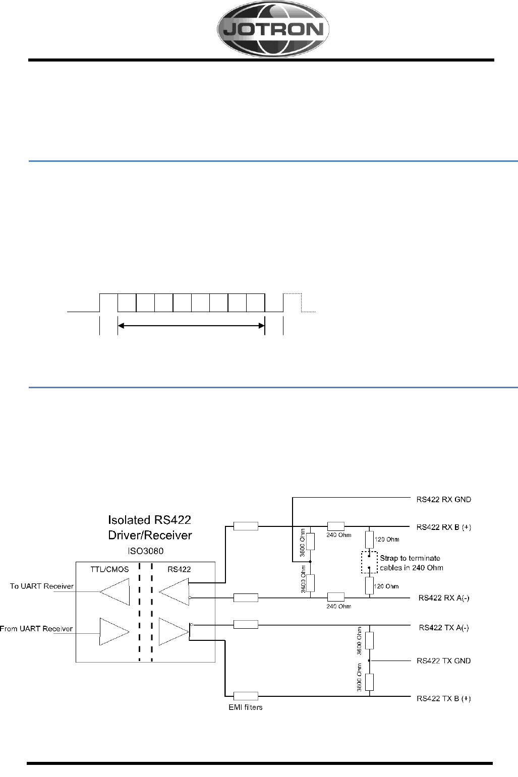
Data is transmitted in serial asynchronous form in accordance with the standards referenced in
2.1 of IEC 61162-1/2. The first bit is a start bit and is followed by data bits, least-significant-
bit first, as illustrated by figure below.
The following parameters are used:
- baud rate: 4 800 to 38 400
- data bits: 8 (D7 = 0),
- parity: none;
- stop bits: 1.
3.1.1 RS422 interface
There are 4 RS422 inputs and 3 RS422 I/O ports on the Transceiver unit.
Sensor 1-3 and DGNSS beacon are inputs.
External Display, Pilot Plug and Long Range are IO ports.
The External Display and the Pilot Plug have a fixed baud rate of 38400 because of the amount of data
transferred. The rest of the RS422 ports have adjustable baud rates (4800/9600/19200/38600).
The Driver circuit ISO3080 is galvanically isolated. The connector on the Transponder is 5mm Double Deck
Terminal Strips from WAGO (736-204). On the Display unit, the connector is a circular 12p female connector
from Bulgin (PX0413/12S/PC).
Figure 1: Simplified diagram of the RS422 interface
D0 D1 D2 D3 D4 D5 D6 D7
Start Stop
bit Data bits bit
TR-8000 Technical manual 3-12
3.1.1.1 Electrical characteristics RS422 interface.
Parameter
Test Condition
MIN
TYP
MAX
UNIT
VO Voltage at either bus I/O terminal
A,B
-15
15
V
VID Differential input voltage
A with respect to B
-15
15
V
RL Differential input resistance
w/jumper
232
Ω
Wo/jumper
7680
Ω
VIT(+) Positive going input threshold voltage
IO = -8mA
-85
-10
mV
VIT(-) Negative going input threshold voltage
IO = 8mA
-200
-115
mV
Isolation
60s
2500
Vrms
IO Output current Receiver
-8
8
mA
Differential output voltage magnitude
IO = 0mA, no load
3
4.3
5
V
RL = 54Ω
1.5
2.3
V
RL = 100Ω
2
2.3
V
IO Output current Driver
-60
60
mA
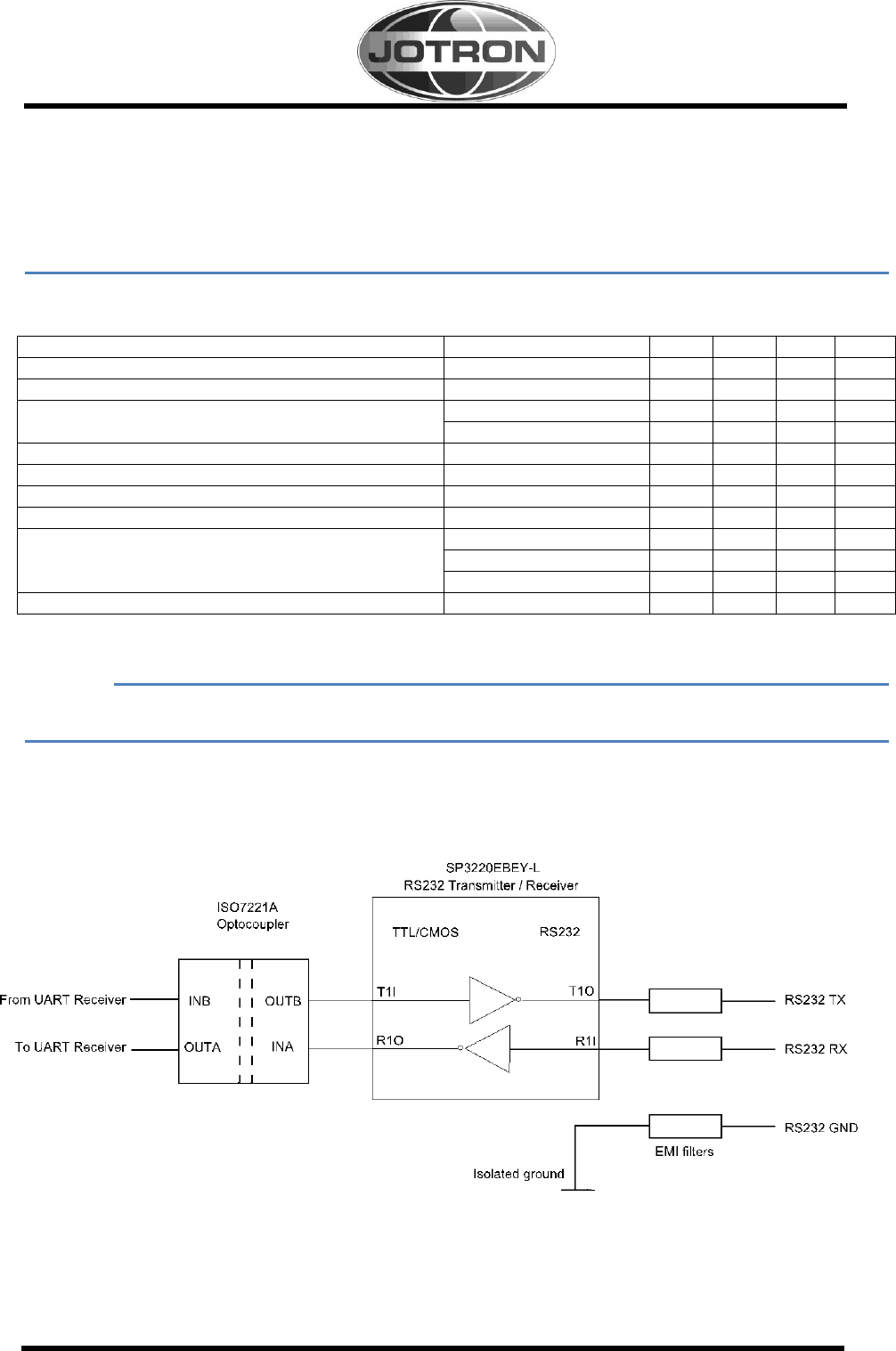
3.1.2 RS232 interface
The functionality if the External Display can be setup by software to use the RS232 port as physical interface
instead of the RS422 port which is default. The baud rate is fixed to 38400. The Interface is galvanically
isolated by an ISO7221A Optocoupler. The connector on the Transponder is 5mm Double Deck Terminal
Strips from WAGO (736-204).
Figure 2: Simplified diagram of the RS232 interface

TR-8000 Technical manual 3-13
3.1.2.1 Electrical characteristics RS232
Min
Typ
Max
Unit
Input Resistance
3
5
7
kΩ
Input Voltage Range
-15
15
V
Input Threshold LOW
0.8
1.5
V
Input Threshold HIGH
1.8
2.4
V
Output Resistance
300
Ω
Output Voltage Swing
±5.0
±5.4
V
Output Short-Circuit Current
±32
±60
mA
3.1.2.2 Display connection
The display is interfaced over Ethernet by LAN8187, enabling data from 10 to 100Mbit/s. The circuit is
galvanically isolated by a transformer and isolated to ground by 2kV capacitors.
The interface is compliant with IEEE 802.3-2005 standards. The connector is a circular RJ45 connector,
Bulgin PX0833/E on the Transponder and PX0839/PC on the Display Unit.
The default IP address of the Transponder is 10.0.0.10 and
the default IP address of the Display Unit is 10.0.0.11.
3.1.2.3 Alarm relay
The Alarm relay is a mandatory normally open earth free relay contact, provided as an independent and
simple method for triggering an external alarm. The alarm relay is active in case of power off and is capable
of driving a 2A current. The relay is implemented as a FET-switch, using FDS3992 Dual N-Channel
PowerTrench® MOSFET. . The connector on the Transponder is 5mm Double Deck Terminal Strips from
WAGO (736-204).
Min
Typ.
Max
Unit
Voltage
48
V
Current
2
A
Resistance
124
mΩ

TR-8000 Technical manual 4-14
4 DESCRIPTION OF SENTENCE FORMAT
The following provides a summary explanation of the approved sentence structure according to IEC 61162:
$aaccc, c---c*hh<CR><LF>
ASCII
HEX
Description
"$"
24
Start of sentence: starting delimiter
aaccc
Address field: alphanumeric characters identifying type of talker,
and sentence formatter. The first two characters identify the
talker. The last three are the sentence formatter mnemonic code
identifying the data type and the string format of the successive
fields. Mnemonics will be used as far as possible to facilitate
read-outs by users.
","
2C
Field delimiter: starts each field except address and checksum
fields. If it is followed by a null field, it is all that remains to
indicate no data in a field.
c---c
Data sentence block: follows address field and is a series of data
fields containing all of the data to be transmitted. Data field
sequence is fixed and identified by the third and subsequent
characters of the address field (the sentence formatter). Data
fields may be of variable length and are preceded by delimiters ",".
"*"
2A
checksum delimiter: follows last data field of the sentence. It
indicates that the following two alpha-numeric characters show
the HEX value of the checksum.
hh
Checksum field: the absolute value calculated by exclusive-
OR'ing the eight data bits (no start bits or stop bits) of each
character in the sentence between, but excluding, "$" and "*".
The hexadecimal value of the most significant and least
significant four bits of the result are converted to two ASCII
characters (0-9, A-F) for transmission. The most significant
character is transmitted first. The checksum field is required in all
cases.
<CR><LF>
0D 0A
End of sentence: sentence terminating delimiter.

TR-8000 Technical manual 4-15
4.1 Input
4.1.1 ABM - Addressed Binary and safety related Message
Support for ITU-R M.1371 messages 6, 12, 25, 26, 70 and 71
Provides an external application with a means to exchange data using the AIS.
!--ABM,x,x,x,xxxxxxxxx,x,x.x,s--s,x*hh<CR><LF>
Number of fill-bits, 0-5
Encapsulated data
ITU-R M.1371 message ID 6, 12, 25, 26, 70, 71
AIS channel for broadcast of the radio message
The MMSI of destination AIS unit for the ITU-R M.1371 message
Sequential Message identifier
Sentence number
Total number of sentences needed to transfer the message
4.1.2 ACA - AIS Regional Channel Assignment Message
This sentence is used to both enter and obtain channel management information.
$--ACA,x,llll.ll,a,yyyyy.yy,a,llll.ll,a,yyyyy.yy,a,x,xxxx,x,xxxx,x,x,x,a,x,hhmmss.ss*hh<CR><LF>
Time of “in-use” change
In-Use Flag
Information source
Power level control
Tx/Rx mode control
Channel B bandwidth
Channel B
Channel A bandwidth
Channel A
Transition Zone Size
Region Southwest corner longitude - E/W
Region Southwest corner latitude - N/S
Region Northeast corner longitude - E/W
Region Northeast corner latitude - N/S
Sequence Number, 0 to 9
4.1.3 ACK - Acknowledge alarm
This sentence is used to acknowledge an alarm condition reported by a device.
$--ACK,xxx,*hh<CR><LF>
Identification number of alarm source

TR-8000 Technical manual 4-16
4.1.4 AIR - AIS Interrogation Request
This sentence supports ITU-R M.1371 message 15. It provides an external application with the
means to initiate a request for specific ITU-R M.1371 messages from distant mobile or base AIS
stations.
$--AIR,xxxxxxxxx,x.x,x,x.x,x,xxxxxxxxx,x.x,x*hh<CR><LF>
Message sub-section (Reserved for future use)
Number of message requested from station-2
MMSI of interrogated station-2
Message sub-section (Reserved for future use)
Number of second message from station-1
Message sub-section (Reserved for future use)
ITU-R M.1371 message requested from station-1
MMSI of interrogated station-1
4.1.5 AIQ - Query Sentence
This sentence is used to query some of the other messages from the AIS. The queries which will be
answered are: ACA, SSD, TRL, TXT, VER and VSD.
$--AIQ,XXX.
Queried Sentence
4.1.6 BBM - Broadcast Binary Message
Support for ITU-R M.1371 messages 8, 14, 25, 26, 70 and 71
It provides an external application with a means to broadcast data, as defined by the application
only - not the AIS.
!--BBM,x,x,x,x,x.x,s--s,x*hh<CR><LF>
Number of fill-bits , 0 to 5
Encapsulated data
ITU-R M.1371 message ID, 8, 14, 25, 26, 70, 71
AIS channel for broadcast of the radio message
Sequential message identifier, 0 to 9
Sentence number, 1 to 9
Total number of sentences needed to transfer the message, 1 to 9

TR-8000 Technical manual 4-17
4.1.7 DTM Datum reference
Local geodetic datum and datum offsets from a reference datum
$--DTM,W84,a,x.x,a,x.x,a, x.x,ccc*hh<CR><LF>
Reference datum 1
Altitude offset, (meter) (Not used)
Longitude offset, min, E/W (Not used)
Lat offset, min, N/S (Not used)
Local datum subdivision code (Not used)
Local datum must be W84 if valid position shall be accepted on sensor port
Note 1: WGS84 = W84
WGS72 = W72
SGS85 = S85
PE90 = P90
User defined =999 (only available for “Local datum”)
IHO datum code
Important: If a DTM sentence is received, it MUST contain “W84” as “Local Datum”, otherwise position information
received in GGA, GLL, RMC or GNS on that sensor port will be rejected.
4.1.8 EPV – Command or report equipment property value
This sentence is used to set the properties of the AIS unit, the message is replied with the
set value as an ack when the value is set.
$--EPV,a,cc,c--c,x.x,c--c,*hh<CR><LF>
Value of property to be set
Property identifier for the property to be set (see Note 3)
MMSI
Destination equipment type (see Note 2)
Sentence status flag (see Note 1)
Note 1: Sentence status flag:
C = Command
R = Response
<Empty field> = request value
Note 2: Indicates which equipment type. Indicated by the Talker Id. Every Talker Id has defined a set of Property
Identifier. Supported values are AI and JTR.
Note 3: The property identifier is a variable length integer field that identifies a parameter that can be set in accordance
with the table below and is intended for commissioning settings.
Proprietary Property Identifiers (for equipment type “JTR”) will be provided to manufacturer of display system on
request.
The following Property Identifiers in are permitted for the equipment type “AI”:

TR-8000 Technical manual 4-18
Property Identifier
Property Meaning
Value range
0-100
Reserved
101
Sensor 1 baud
4800, 9600, 14400,
19200, 38400
102
Sensor 2 baud
4800, 9600, 14400,
19200, 38400
103
Sensor 3 baud
4800, 9600, 14400,
19200, 38400
104
Long Range baud
4800, 9600, 14400,
19200, 38400
105
DGNSS baud
4800, 9600, 14400,
19200, 38400
106
MMSI
000000000, 200000000
… 799999999
107
IMO Number
0000000 … 9999999
108
Long Range
configuration
“A” = automatic
“M” = manual
109
Long Range AIS
channel 1
Valid channel according
ITU-R M.1084-4
110
Long Range AIS
channel 2
Valid channel according
ITU-R M.1084-4
111
Change administrator
password
New administrator
password
112
Change user password
New user password
113
AIS-SART test mode
0 = normal mode
1 = display and output
AIS-SART in test mode
All other values
Reserved
Table 2 Standard Ais Property Identifier for Destination Equipment "AI"

TR-8000 Technical manual 4-19
4.1.9 GBS - GNSS satellite fault detection
This message is used to support receiver autonomous integrity monitoring (RAIM). Given that a
GNSS receiver is tracking enough satellites to perform integrity checks of the positioning quality of
the position solution; a message is needed to report the output of this process to other systems to
advise the system user. With the RAIM in the GNSS receiver, the receiver can isolate faults to
individual satellites and not use them in its position and velocity calculations.
Also, the GNSS receiver can still track the satellite and easily judge when it is back within
tolerance.
This message shall be used for reporting this RAIM information. To perform this integrity function,
the GPS receiver must have at least two observables in addition to the minimum required for
navigation. Normally these observables take the form of additional redundant satellites.
$--GBS, hhmmss.ss, x.x, x.x, x.x, xx, x.x, x.x, x.x,h,h*hh <CR><LF>
4.1.10 GGA - Global positioning system (GPS) fix data
Time, position and fix-related data for a GPS receiver.
$--GGA, hhmmss.ss, llll.ll, a, yyyyy.yy, a, x, xx, x.x, x.x, M, x.x, M, x.x, xxxx*hh<CR><LF>
Differential reference station ID
0000-1023 (Not used)
Age of diff. GPS data (Not used)
Units of geoidal separation,m (Not
used)
Geoidal separation (Not used)
Units of antenna altitude, m (Not
used)
Antenna altitude above/below
mean sea level (geoid) (Not used)
Horizontal dilution of precision (Not
used)
No. of satellites in use, 00-12 (Not
used)
GPS quality indicator
Longitude E/W
Latitude N/S
UTC time of position
GNSS Signal ID
GNSS System ID
Standard deviation of bias estimate (Not used)
ID number of most likely failed satellite (Not used)
Estimate of bias on most likely failed satellite (Not used)
Probability of missed detection for most likely failed satellite (Not
used)
Expected error in altitude (Not used)
Expected error in longitude
Expected error in latitude
UTC time of the GGA or GNS fix associated with this sentence

TR-8000 Technical manual 4-20
4.1.11 GLL - Geographic position - latitude/longitude
Latitude and longitude of vessel position, time of position fix and status.
$--GLL, llll.ll, a, yyyyy.yy, a, hhmmss.ss, A, a *hh<CR><LF>
Mode indicator (see Note 1)
Status: A = data valid V = data invalid
Time of position (UTC)
Longitude , E/W
Latitude, N/S
Note 1: Positioning system Mode indicator:
A = Autonomous
D = Differential
E = Estimated (dead reckoning)
M = Manual input
S = Simulator
N = Data not valid
4.1.12 GNS - GNSS fix data
Fix data for single or combined satellite navigation systems (GNSS). This sentence provides fix
data for GPS, GLONASS, possible future satellite systems and systems combining these.
$-- GNS, hhmmss.ss, llll.ll, a, yyyyy.yy, a, c--c,xx,x.x,x.x,x.x,x.x,x.x,a *hh<CR><LF>
Navigation status indicator
Differential reference station ID (Not used)
Age of differential data (Not used)
Geoidal separation, m (Not used)
Antenna altitude, m, re:mean-sea-level (Not
used)
Horizontal dilution of precision (HDOP) (Not
used)
Number of satellites in use, 00-99 (Not used)
Mode indicator
Longitude E/W
Latitude N/S
Time of position (UTC)
4.1.13 HBT Heart Beat
This sentence is intended to be used to indicate that equipment is operating normally, or for supervision of a
connection between two units.
$--HBT, x.x,A,x*hh <CR><LF>
Sequencial sentence identifier
Equipment status (A=normal operation, V=no normal operation
Configured repeat interval

TR-8000 Technical manual 4-21
4.1.14 HDT - Heading true
IMO Resolutions A.424 and A.821. Actual vessel heading in degrees true produced by any device
or system producing true heading
$--HDT, x.x, T*hh<CR><LF>
Heading, degrees true
4.1.15 LRF - Long Range Function
This sentence is used in both long-range interrogation requests and long-range interrogation replies.
$--LRF,x,xxxxxxxxx,c--c,c--c,c--c*hh<CR><LF>
Function reply status 1
Function request, 1 to 26 characters
Name of requestor, 1 to 20 character string
MMSI of requestor
Sequence number , 0 to 9
Note 1:
The "Function Reply Status" field provides the status characters for the "Function Request" information. When a long-range
interrogation request is originated, the "Function Reply Status" field should be null. The "Function Reply Status" characters are
organised in the same order as the corresponding function identification characters in the "Function Request" field. The following is a list
of the "Function Reply Status" characters with the status they represent:
2 = Information available and provided in the following LR1, LR2, or LR3 sentence,
3 = Information not available from AIS unit,
4 = Information is available but not provided (i.e. restricted access determined by ship's master),
4.1.16 LRI - Long-Range Interrogation
The long-range interrogation of the AIS is accomplished through the use of two sentences.
The pair of interrogation sentences, a LRI-sentence followed by a LRF-sentence, provides the
information needed by the AIS to determine if it must construct and provide the reply sentences (LRF,
LR1, LR2, and LR3)
$--LRI,x,a,xxxxxxxxx,xxxxxxxxx,llll.ll,a,yyyyy.yy,a,llll.ll,a,yyyyy.yy,a*hh<CR><LF>
Longitude - E/W (south-west co-ordinate)
Latitude - N/S ( -“- -“- “ -“- )
Longitude - E/W (north-east co-ordinate)
Latitude - N/S ( -“- -“- “ -“- )
MMSI of "destination"
MMSI of "requestor"
Control Flag
Sequence number, 0-9

TR-8000 Technical manual 4-22
4.1.17 OSD Own ship data
IMO Resolution A.477 and MSC 64(67), Annex 1 and Annex 3. Heading, course, speed, set and
drift summary. Useful for, but not limited to radar/ARPA applications. OSD gives the movement
vector of the ship based on the sensors and parameters in use.
$--OSD, x.x,A,x.x, a,x.x,a,x.x,x.x,a*hh<CR><LF>
Speed units, K = km/h; N = Knots, S = statute miles/h
Vessel drift (speed), (Manually entered) (Not used)
Vessel set, degrees true, (Manually entered) (Not used)
Speed reference,B/M/W/R/P , see note
Vessel speed
Course reference, B/M/W/R/P ,see note
Vessel course, degrees true
Heading status, A= valid data, V= invalid data
Heading, degrees true
4.1.18 RMC Recommended minimum specific GNSS data
Time, date, position, course and speed data provided by a GNSS navigation receiver. This sentence
is transmitted at intervals not exceeding 2 s. All data fields must be provided, null fields used only
when data is temporarily unavailable.
$--RMC, hhmmss.ss, A, llll.ll,a, yyyyy.yy, a, x.x, x.x, xxxxxx, x.x,a, a, a*hh<CR><LF>
Navigation Status
Mode indicator (see Note 1)
Magnetic variation, degrees, E/W (Not
used)
Date: dd/mm/yy (Not used)
Course over ground, degrees true
Speed over ground, knots
Longitude, E/W
Latitude, N/S
Status: A = data valid V = navigation
receiver warning
Time of position fix (UTC)
Note 1: Positioning system Mode indicator:
A = Autonomous mode
D = Differential mode
E = Estimated (dead reckoning) mode
M = Manual input mode
S = Simulator mode
N = No fix
P = Precise
R = Real time kinematic
S = Simulator mode

TR-8000 Technical manual 4-23
4.1.19 ROT - Rate of turn
IMO Resolution A.526. Rate of turn and direction of turn.
$--ROT, x.x, A*hh<CR><LF>
Status: A = data valid, V = data invalid
Rate of turn, °/min, "-" = bow turns to port
4.1.20 SPW - Security password sentence
This sentence can be used for authentication. For this purpose the sentence has to be applied before
the protected sentence (for example EPV, SSD).
Other sentences may not be interleaved between the password sentence and protected sentence and
the time between the SPW and the protected sentence should be limited. The password protected
sentence pair should be sent without unnecessary delay between sentences. The recommendation is
1 s maximum timeout. Note that any of the signals may be lost and timed out.
If the password is not accepted (for example because it is incorrect) the command is refused using
the NAK sentence.
$--SPW,ccc,c--c,x,c--c*hh<CR><LF>
Password as text, up to 32 char
Password level (see Note 1)
MMSI
The following sentence formatter that should be protected (for example EPV)
Note 1: An integer number as defined below:
1 = User level password
2 = Administrator level password
3-9 = Reserved
4.1.21 SSD - Station static data
This sentence is used to enter static parameters into a shipboard AIS. The parameters in this
sentence support a number of the ITU-R M.1371 messages.
$--SSD,c--c,c--c,xxx,xxx,xx,xx,c,aa*hh<CR><LF>
Source identifier
DTE indicator flag
Pos. ref., "D," distance from starboard beam, 0 to 63 metres
Pos. ref., "C," distance from port beam, 0 to 63 metres
Pos. ref., "B," distance from stern, 0 to 511 metres
Pos. ref., "A," distance from bow, 0 to 511 metres
Ship's Name, 1 to 20 characters
Ship's Call Sign, 1 to 7 characters

TR-8000 Technical manual 4-24
4.1.22 VBW - Dual ground/water speed
Water-referenced and ground-referenced speed data
$--VBW, x.x, x.x, A, x.x, x.x, A, x.x, A, x.x, A*hh<CR><LF>
Status: stern ground speed, (A = data valid, V = data invalid) (Not used)
Stern transverse ground speed, knots (Not used)
Status: stern water speed, (A = data valid, V = data invalid) (Not used)
Stern transverse water speed, knots (Not used)
Status, ground speed, (A = data valid, V = data invalid)
Transverse ground speed, knots (see Note 1)
Longitudinal ground speed, knots (see Note 1)
Status: water speed, (A = data valid, V = data invalid) (Not used)
Transverse water speed, knots (Not used)
Longitudinal water speed, knots (Not used)
Note 1: Transverse speed: "-" = port, Longitudinal speed: "-" = astern.
4.1.23 VSD - Voyage Static Data
This sentence is used to enter information about a ship's voyage.
$--VSD,x.x,x.x,x.x,c--c,hhmmss.ss,xx,xx,x.x,x.x*hh<CR><LF>
Regional application flags, 0 to 15
Navigational status, 0 to 15
Estimated month of arrival at destination, 00 to 12 (UTC)
Estimated day of arrival at destination, 00 to 31 (UTC
Estimated time of arrival at destination (UTC)
Destination, 1-20 characters
Persons on-board, 0 to 8191
Maximum present static draught, 0 to 25,5 metre
Type of ship and cargo category, 0 to 255
4.1.24 VTG - Course over ground and ground speed
The actual course and speed relative to the ground.
$--VTG, x.x, T, x.x, M, x.x, N, x.x, K,a*hh<CR><LF>
Mode indicator (see Note 1)
Speed over ground, km/h
Speed over ground, knots
Course over ground, degrees magnetic (Not used)
Course over ground, degrees true
Note 1: Positioning system Mode indicator:
A = Autonomous mode
D = Differential mode
E = Estimated (dead reckoning) mode
M = Manual input mode
P = Precise
S = Simulator mode
N = Data not valid
The positioning system Mode indicator field shall not be a null field.

TR-8000 Technical manual 4-25
4.1.25 ZDA – Time and date
UTC, day, month, year and local time zone.
$--ZDA, hhmmss.ss, xx, xx, xxxx, xx, xx*hh<CR><LF>
Local zone minutes (see Note 1),
00 to +59
Local zone hours (see Note 1), 00 h to ±13 h
Year (UTC)
Month, 01 to 12 (UTC)
Day, 01 to 31 (UTC)
UTC
Note 1: Local time zone is the magnitude of hours plus the magnitude of minutes added, with the sign of local zone
hours, to local time to obtain UTC. Local zone is generally negative for East longitudes with local exceptions near the
international date line.
4.2 Output
All sentences starts with a delimiter that can be “$” or “!” followed by the talker identifier indicated
by “- -“. The talker identifier is AI for AIS.
4.2.1 ABK - Addressed and binary broadcast acknowledgement
The ABK-sentence is generated when a transaction, initiated by reception of an ABM, AIR, or
BBM sentence is completed or terminated.
$--ABK,xxxxxxxxx,a,x.x,x,x*hh<CR><LF>
Type of acknowledgement
Message Sequence Number
ITU-R M.1371 message ID
AIS channel of reception
MMSI of the addressed destination AIS unit
4.2.2 ACA See “Input “
4.2.3 ALR - Set alarm state
Local alarm condition and status. This sentence is used to report an alarm condition on a device and
its current state of acknowledgement.
$--ALR,hhmmss.ss,xxx,A, A,c--c*hh<CR><LF>
Alarm's description text
Alarm's acknowledge state, A = acknowledged
V = unacknowledged
Alarm condition (A = threshold exceeded, V = not exceeded)
Local alarm number (identifier)
Time of alarm condition change, UTC
TR-8000 Technical manual 4-26
4.2.4 EPV See “Input “
4.2.5 HBT See “Input “
4.2.6 LRF See “Input “
4.2.7 LR1 - Long-range Reply with destination for function request "A"
The LR1-sentence identifies the destination for the reply and contains the information requested by
the "A" function identification character.
$--LR1,x,xxxxxxxxx,xxxxxxxxx,c--c,c--c,xxxxxxxxx*hh<CR><LF>
IMO Number, 9-digit number
Call Sign, 1 to 7 characters
Ship's name, 1 to 20 characters
MMSI of requestor (reply destination)
MMSI of responder
Sequence Number, 0 to 9
4.2.8 LR2 - Long-range Reply for function requests "B, C, E, and F"
The LR2-sentence contains the information requested by the "B, C, E, and F" function identification
characters.
$--LR2,x,xxxxxxxxx,xxxxxxxx,hhmmss.ss,llll.ll,a,yyyyy.yy,a,x.x,T,x.x,N*hh<CR><LF>
Speed over ground, knots
Course over ground, degrees True
Longitude, E/W
Latitude, N/S
Time of position, UTC
Date: ddmmyyyy, 8 digits
MMSI of responder
Sequence Number, 0 to 9
4.2.9 LR3 - Long-range Reply for function requests "I, O, P, U and W"
The LR3-sentence contains the information requested by the "I, O, P, U, and W" function
identification characters
$--LR3,x,xxxxxxxxx,c--c,xxxxxx,hhmmss.ss,x.x,cc,x.x,x.x,x.x,x.x*hh<CR><LF>
Persons, 0 to 8191
Ship type
Ship breadth, value to nearest metre
Ship length, value to nearest metre
Ship/cargo (ITU-R M.1371, Table 18)
Draught, value to 0,1 metre
ETA Time, value to nearest second
ETA Date: ddmmyy
Voyage destination, 1 to 20 characters
MMSI of "responder"
Sequence Number, 0 to 9

TR-8000 Technical manual 4-27
4.2.10 NAK – Negative acknowledgement
In general, the NAK sentence is used when a reply to a query sentence cannot be provided,
or when a command sentence is not accepted. The NAK sentence reply should be generated within
1 s.
$--NAK,cc,ccc,c--c,x.x,c--c*hh<CR><LF>
Negative acknowledgement’s descriptive text
Reason code for negative acknowledgement (see Note 1)
Unique identifier
Affected sentence formatter
Talker identifier
Note 1: Reason codes:
0 = query functionality not supported;
1 = sentence formatter not supported;
2 = sentence formatter supported, but not enabled;
3 = sentence formatter supported and enabled, but temporarily unavailable (for instance, data field problem,
unit in initialize state, or in diagnostic state, etc.);
4 = sentence formatter supported, but query for this sentence formatter is not supported;
5 = access denied, for sentence formatter requested;
6 = sentence not accepted due to bad checksum;
7 = sentence not accepted due to listener processing issue;
8 to 9 = reserved for future use;
10 = cannot perform the requested operation;
11 = cannot fulfil request or command because of a problem with a data field in the sentence;
12 to 48 = reserved for future use;
49 = other reason as described in data field 5.
Values greater than 50 may be defined by equipment standards.
4.2.11 TRL – AIS transmitter non functioning log
This sentence is used to output the logged “transmitter non-functioning” times. On a query (AIQ)
for this sentence, up to 10 sentences will be output, one sentence for each logged non-functioning
time.
This sentence is always generated as a response to a query even when no log entries exist.
$--TRL,x.x,x.x,x,xxxxxxxx,hhmmss.ss,xxxxxxxx,hhmmss.ss,x,*hh<CR><LF>
Reason Code (See Note 1)
Switch on UTC time
Switch on date
Switch off UTC time
Switch off date (ddmmyyyy)
Sequential message identifier
Log entry number
Total number of log entries
Note 1: Reason for Tx non-functioning:
1 = power off
2 = silent mode
3 = transmission switched off by channel management command
4 = equipment malfunction
5 = invalid configuration

TR-8000 Technical manual 4-28
4.2.12 TXT - Text transmission
For the transmission of short text messages. Longer text messages may be transmitted by using
multiple sentences.
$--TXT,xx,xx,xx,c--c*hh<CR><LF>
Text message, ASCII, up to 61 characters
Text identifier, 01-99
Message number, 01 to 99
Total number of messages, 01 to 99
4.2.13 VDM - VHF Data-link Message
This sentence is used to transfer the entire contents of a received AIS message packet, as defined in
ITU-R M.1371 and as received on the VHF Data Link (VDL), using the "6-bit" field type.
!--VDM,x,x,x,a,s--s,x*hh<CR><LF>
Number of fill-bits, 0 to 5
Encapsulated ITU-R M.1371 radio message
AIS Channel, "A" or "B"
Sequential message identifier, 0 to 9
Sentence number, 1 to 9
Total number of sentences needed to transfer the message, 1 to 9
4.2.14 VDO - VHF Data-link Own-vessel message
This sentence is used to provide the information assembled for broadcast by the AIS. It uses the six-
bit field type for encapsulation. The sentence uses the same structure as the VDM sentence
formatter.
!--VDO,x,x,x,a,s--s,x*hh<CR><LF>
Number of fill-bits, 0 to 5
Encapsulated ITU-R M.1371 radio message
AIS Channel, "A" or "B"
Sequential message identifier, 0 to 9
Sentence number, 1 to 9
Total number of sentences needed to transfer the message, 1 to 9

TR-8000 Technical manual 4-29
4.2.15 VER – Version
This sentence is used to provide identification and version information about a device. This sentence is
produced as reply to a query sentence.
$--VER,x,x,aa,c--c,c--c,c--c, c--c,c--c,c--c,x *hh <CR><LF>
Sequencial message identifier
Hardware revision
Software revision
Unique identifier
Model code (product code)
Manufacturer serial number
Vendor ID
Device Type
Sentence number, 1 to 9
Total number of sentences needed, 1 to 9

TR-8000 Technical manual 5-30
5 Abbreviations and Definitions
ACK Acknowledge
AIS Automatic Identification System - A shipborne broadcast transponder system in which ships
continually transmit their position, course, speed and other data to other nearby ships and
shoreline authorities on a common VHF radio channel.
AIS-SART Automatic Identification System-Search And Rescue Transponder
AtoN Aid to Navigation
BAUD Transmission rate unit of measurement for binary coded data (bit per second).
BNC Bayonet Neill-Concelman connector – common type of RF connector used for coaxial cable
BRG Bearing
CPA Closest Point of Approach
COG Course Over Ground – Course made good relative to the sea bed.
DSC Digital Selective Calling
DGNSS Differential GNSS
DGPS Differential GPS – A method of refining GPS position solution accuracy by modifying the locally
computed position solution with correction signals from an external reference GPS CDU
(monitor).
ECDIS Electronic Chart Display and Information System for navigation approved to be used without
paper charts
ECS Electronic Chart System
EPFS Electronic Position Fixing System (GPS is mostly used)
ETA Estimated Time of Arrival. Calculated on basis of the distance to the destination and the current
(or estimated) speed.
FM Frequency Modulation - The method by which a signal offsets the frequency in order to
modulate it on a data link.
GNSS Global Navigation Satellite System – A common label for satellite navigation systems (such as
GPS and GLONASS).
GPS Global Positioning System – The NAVSTAR Global Positioning System, which consists of or-
biting satellites, a network of ground control stations, and user positioning and navigation
equipment. The system has 24 satellites plus 3 active spare satellites in six orbital planes about
20,200 kilometers above the earth.
GLONASS A satellite navigation system developed and operated by Russia.
GMT Greenwich Mean Time
GMDSS Global Maritime Distress Safety System

TR-8000 Technical manual 5-31
HDG Heading - The direction, in which the vessel is pointed, expressed as angular distance from
north clockwise through 360 degrees. HEADING should not be confused with COURSE. The
HEADING is constantly changing as the vessel yaws back and forth across the course due to
the effects of sea, wind, and steering error.
IALA International Association of Marine Aids to Navigation and Lighthouse Authorities
IEC International Electro-technical Commission
IEC 61162-1 Maritime navigation and radio communication equipment and systems – Digital interfaces
Single Talker- Multiple listeners: Closely related to NMEA0183 version 2.3, communication at
4800 baud. Definition of both electrical interface and protocol to be used.
IEC 61162-2 Maritime navigation and radio communication equipment and systems – Digital interfaces
Single Talker- Multiple listeners, High speed transmission: Closely related to NMEA0183HS
version 2.3, communication at 34800 baud. Definition of both electrical interface and protocol to
be used.
IMO International Maritime Organization
IP Internet Protocol (IP) is the central, unifying protocol in the TCP/IP suite. It provides the basic
delivery mechanism for packets of data sent between all systems on an internet, regardless of
whether the systems are in the same room or on opposite sides of the world. All other protocols
in the TCP/IP suite depend on IP to carry out the fundamental function of moving packets
across the internet.
ISGOTT International Safety Guide for Oil Tankers and Terminals
ITU International Telecommunication Union
LAN Local Area Network
LED Light Emitting Diode
LCD Liquid Crystal Display
LR Long Range
NMEA National Marine Electronics Association – The NMEA electronics interface specifications have
been developed under the auspices of the Association. The NMEA 0183 is an internationally
recognized specification for interfacing marine electronics. NMEA 0183 version 2.3 is almost
identical to lEC 61162-1.
MKD Minimum Keyboard and Display
MMSI Maritime Mobile Service Identity
RCC Rescue Coordination Centre
RF Radio Frequency
RMS ROOT MEAN SQUARED – A statistical measure of probability stating that an expected event
will happen 68% of the time. In terms of position update accuracy, 68 position updates out of
100 will be accurate to within specified system accuracy.
ROT Rate Of Turn

TR-8000 Technical manual 5-32
RNG Range
RX RX is the telegraph and radio abbreviation for “receive”
SAR Search And Rescue
S/N Signal-to-Noise ratio (SIN). Quantitative relationship between the useful and non-useful part of
the received satellite signal. A high SIN indicates a good receiving condition.
SOG Speed Over Ground – Speed in relation to the seabed.
SOTMA Self Organized Time Division Multiple Access -An access protocol, which allows autonomous
operation on a data link while automatically resolving transmission conflicts.
TCP Transmission Control Protocol – Provides a reliable byte-stream transfer service between two
end points on an internet. TCP depends on IP to move packets around the network on its
behalf.
TCP/IP TCP/IP is a name given to the collection (or suite) of networking protocols that have been used
to construct the global Internet. The protocols are also referred to as the DoD (dee-oh-dee) or
Arpanet protocol suite because their early development was funded by the Advanced Research
Projects Agency (ARPA) of the US Department of Defense (DoD).
TCPA Time to Closest Point of Approach
TI Turn Indicator
TNC Threaded Neill-Concelman connector – common type of RF connector used for coaxial cable
TX TX is the telegraph and radio abbreviation for “transmit”
UDP User Datagram Protocol – Provides a packetized data transfer service between end points on
an internet. UDP depends on IP to move packets around the network on its behalf.
UTC Universal Time Coordinated – Greenwich mean time corrected for polar motion of the Earth and
seasonal variation in the Earth's rotation.
VDC Volt DC
VDL VHF Data Link
VHF Very High Frequency – A set of frequencies in the MHz region
VSWR Voltage standing wave ratio

Jotron AS (HQ)
P.O.Box 54
3281 Tjodalyng
Norway
Tel: +47 33 13 97 00
Fax: +47 33 12 67 80
sales@jotron.com
CONTACT INFORMATION
Jotron AS
P.O.Box 23
3195 Skoppum
Norway
Tel: +47 33 13 97 00
Fax: +47 33 12 67 80
sales@jotron.com
Jotron AS
Dølasletta 7
3408 Tranby
Norway
Tel: +47 32 84 53 87
Fax: +47 32 84 55 30
sales@jotron.com
Jotron UK Ltd.
Crosland Park
Cramlington
NE23 1LA
United Kingdom
Tel: +44 (0) 1670 712000
Fax: +44 (0) 1670 590265
sales@jotron.com
Jotron USA, Inc.
10645 Richmond Avenue
Suite 170
Houston, TX 77042
USA
Tel: +1 713 268 1061
Fax: +1 713 268 1062
sales@jotron.com
Jotron Asia Pte. Ltd.
19 Loyang Way
Changi Logistics Centre
Rear Office Block 04-26
Singapore 508724
Tel: +65 65426350
Fax: +65 65429415
sales@jotron.com