Jotron AS TR8000 Tron AIS TR-8000 User Manual Operator and Installation Manual part 3
Jotron AS Tron AIS TR-8000 Operator and Installation Manual part 3
Contents
- 1. Technical Manual
- 2. Operator and Installation Manual part 1
- 3. Operator and Installation Manual part1
- 4. Operator and Installation Manual part 2
- 5. Operator and Installation Manual part 3
Operator and Installation Manual part 3
TR-8000 Operator and Installation Manual 71
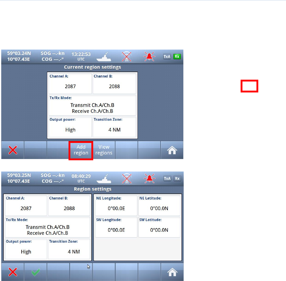
10.1.3.3 Add Region
The user is allowed to Add Regions, but caution is advised (see 10.1.3).
It is not allowed to delete regions, they will be deleted on timeout after 24 hours inactivity, if the ship is
more than 500NM away from the region, or if the region is overwritten. There is a maximum amount of
8 regions in addition to the HIGH SEA region
Red square shows
button selected to get to next
menu
When “Add Region” is selected,
default values for Channels, Tx/Rx
Mode, Power and Transition zone
are configured, but all these
parameters may be altered
together with defining position of
the North East and South West
corners of the Region.
TR-8000 Operator and Installation Manual 72
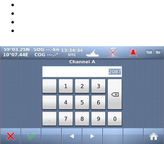
10.1.3.3.1 Change Channel
NOTE! BE AWARE THAT SETTING OF CHANNELS WITHOUT SPECIFIC KNOWLEDGE OF CORRECT SETTING
MAY ALTER YOUR AND OTHER VESSELS SECURITY AS:
YOU MAY TRANSMIT ON ILLEGAL CHANNELS
YOU MAY NOT BE SEEN ON OTHER VESSELS AIS
OTHERS MAY NOT SEE YOU
THIS CAN IN WORST CASE LEAD TO COLLISIONS
When you select either the buttons “Channel
A” or “Channel B” you may input the correct
channel number.
The default channels 2087 and 2088 are the
same as 87B or 88B used previously as Coast
Station frequencies on 161.975 MHz and
162.025 MHz.
See complete list in Chapter 12 and for
updates of this list from ITU RR, Appendix 18
TR-8000 Operator and Installation Manual 73
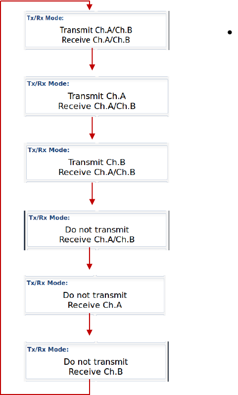
10.1.3.3.2 Tx/Rx Mode
Tx/Rx Mode allows you to change setting in which the transponders will use the two regional channels
for transmission (Tx) and reception (Rx)
When you press the button “Tx/Rx Mode” it will toggle between the valid configurations:
Default – will transmit/receive on both channels
TR-8000 Operator and Installation Manual 74
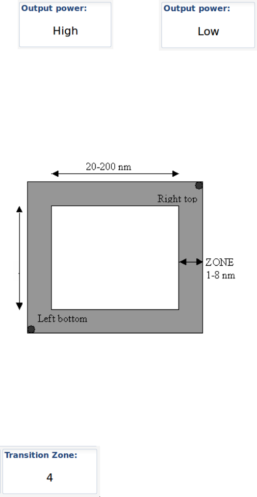
10.1.3.3.3 Output Power
The button “Output Power” will toggle between “High” and “Low” power:
(12.5 Watts) (1 Watt )
10.1.3.3.4 Transition Zone
A Region must be between 20 an 200 Nautical miles and within this region there will be a “Transition
zone” between 1 and 8 Nautical miles:
This zone is used for frequency transition so only
one frequency is changed at a time. There are
defined rules for how the AIS will behave
through this zone.
The AIS will continuously monitor for its own
position and range to the regional areas defined.
When entering transition zone for Region 1,
frequency is changed on the primary channel.
The AIS is now sending the primary frequency
defined for each of the regions.
When the boundary for the Region 1 is crossed,
the second frequency shall be changed. Then the primary frequency for the old region (or default
setting) is switched with the secondary frequency for the new region. Then both frequencies have
changed.
When entering another region, frequency transition is performed as described above with the
frequencies (settings) of the new region. When leaving a region, frequency transition is performed back
to default values.
To change the value of this “Transition Zone”, select the button and input value
between 1 and 8 (Nautical miles)
TR-8000 Operator and Installation Manual 75
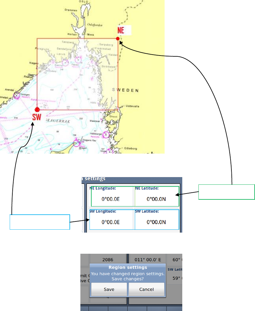
10.1.3.3.5 Define Region
A Region must be between 20 an 200 Nautical miles as described above and you must define the
Longitudes and Latitudes of the South West and North East corners:
The values are defined by selecting these 4 buttons:
If the values are within 20 – 200 NM, they will be accepted, and you will be asked if you want to save it:
Otherwise you may experience errors:
North East corner
South West corner
TR-8000 Operator and Installation Manual 76
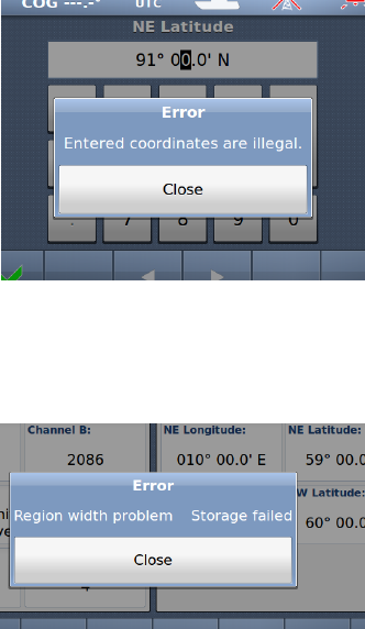
10.1.3.3.5.1 Illegal Coordinates
Example: Too large value for Latitude
10.1.3.3.5.2 Region Width /Height problem
Example: Too large value for “Region width”
TR-8000 Operator and Installation Manual 77
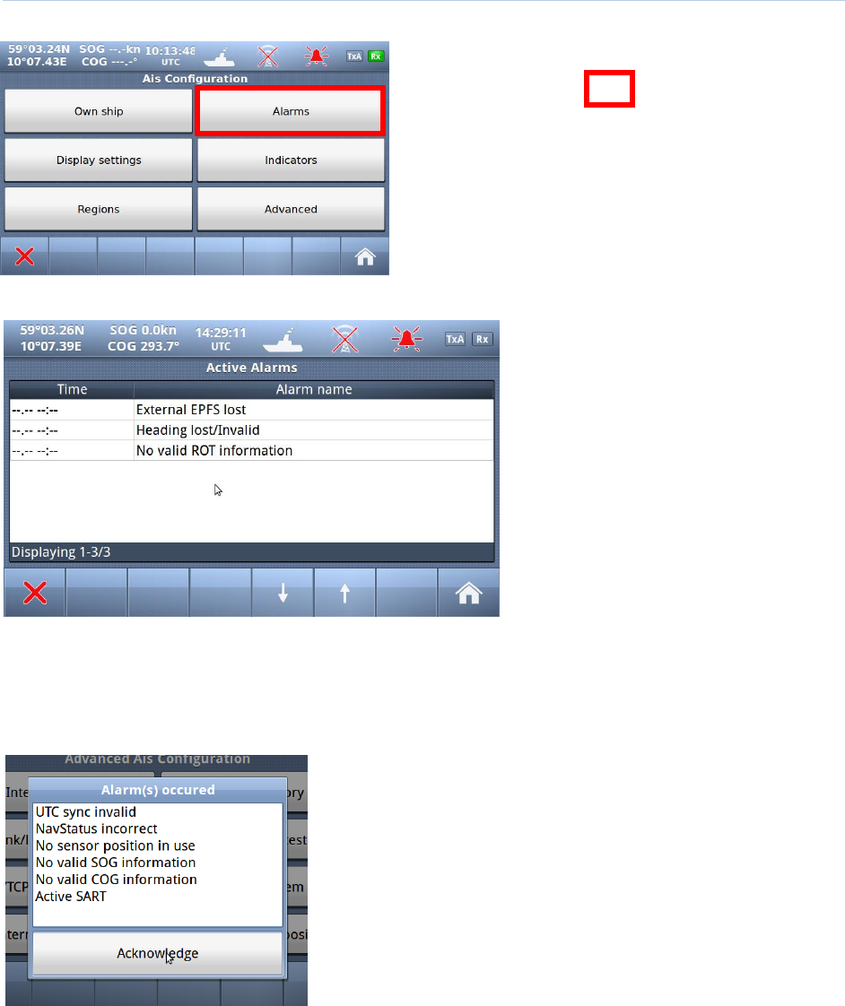
10.1.3.4 Alarms
Red square shows
button selected to get to next menu
10.1.3.4.1 Alarm Popup
When Alarms occurs, a popup will be shown with status of Alarms:
And the “Alarm” popup must be acknowledged by pressing the
button below Alarm window

TR-8000 Operator and Installation Manual 78
The internal Alarm is triggered if a failure is detected in one or more of the AIS functions or data. The
corresponding message is given as in Table 2. The most probable source of error and corresponding
system behavior is described together with some notes on troubleshooting the error.
Alarm
ID
description text
Cause / Source of error
Reaction of the system and
user advise
001
Tx malfunction
VHF Antenna or cabling mismatch.
Alternatively Invalid MMSI
The Transponder stops transmission.
Check the antenna cabling for short or open
circuits. Alternatively check the VHF
antenna. Check that the MMSI number is
correct.
002
Antenna VSWR
(Voltage Standing
Wave Ratio)
exceeds limit
VHF antenna or installation
The Transponder continues transmission.
Check the VHF antenna and the cabling.
Make sure the cables are 50 Ohm
003
Rx channel 1
malfunction
Internal frequency error*
The Transponder stops transmission on the
affected channel.
Try rebooting the system
Alternatively, service is needed
004
Rx channel 2
malfunction
Internal frequency error*
The Transponder stops transmission on the
affected channel.
Try rebooting the system
Alternatively, service is needed.
005
Rx channel 70
malfunction
Internal frequency error*
The Transponder continues normal
transmission but is not able to receive DSC
messages.
Try rebooting the system
Alternatively, service is needed.
006
General failure
Missing MMSI, internal error
The Transponder stops transmission.
Check MMSI and the other parameters.
007
UTC sync invalid
GPS antenna or installation
The Transponder continues operation using
indirect or semaphore synchronisation with
other AIS units.
If the received GPS signal strength is low,
the GPS might use some time to get the
first fix. Consider waiting 15 minutes.
Check the GPS antenna and cabling.
If the antenna is an active type, check that
the phantom DC voltage is correct

TR-8000 Operator and Installation Manual 79
008
MKD connection
lost
Connection between the Display Unit and
the Transponder is corrupted
The Transponder continues operation, and
alerts other AIS systems that no display is
present.
Check that the display is turned on.
Check that the cable is correct connected in
both ends.
Check the IP address and corresponding
communications IP address of both units if
using the Ethernet connection.
Check for firewall error or such if connected
through a local network.
009
Internal / external
GNSS position
mismatch
Internal or External GPS or Antennas
The Transponder continues operation, but
as this might imply that wrong position is
used. Care should be taken as this might
impose a risk both for own and other ships.
Check the positioning of the GPS antennas.
Disconnect the External GPS and check if
the internal GPS provides the correct
position.
010
Navigational
Status incorrect
Setup or speed sensor
(Navigational status does not correspond
with the given speed)
The Transponder continues operation.
Check that navigational status is not at
anchor, moored or aground while SOG >
3knots.
Check that navigational status is not under
way while SOG = 0 knots.
Check that SOG is correct.
011
Heading sensor
offset
COG sensor / HDT sensor
Alarm ID 11 is activated when SOG is
greater than 5 knots and the difference
between COG and HDT is greater than 45
degrees for 5 min.
The Transponder continues operation.
Alarm indicates mismatch between Course
over ground and True heading. Check
sensors. If current speed is <5knots, check
SOG
014
Active AIS SART
AIS Search and rescue beacon activated
The Transponder continues operation.
Contact local RCC (Rescue Coordination
Centre). Be prepared to assist in search
and rescue operation.
Listen on VHF channel 16 for additional
information.
025
External EPFS lost
(External Satellite
Positioning
System)
No valid position data on sensor ports
The Transponder continues operation with
the internal GPS receiver. If no valid
position is present on the internal sensor,
ALR26 is also displayed.
Check antenna and connections for EPFS,
check sensor. Check baud rate settings.
026
No sensor position
in use
Internal and external GPS sensor
The Transponder continues operation.
Check cabling and antenna for the internal
GPS sensor. At start up the GPS might
need some time to receive almanac data.
Up to 15 minutes might be required.
029
No valid SOG
information
Internal and external speed sensor
The Transponder continues operation using
default data.
Check wiring and external sensor.
Check baud rate settings.
030
No valid COG
information
Internal and external course sensor
The Transponder continues operation using
default data.
Check wiring and external sensor.
Check baud rate settings.

TR-8000 Operator and Installation Manual 80
032
Heading
lost/invalid
External heading sensor
The Transponder continues operation using
default data.
Check wiring and external sensor.
Check baud rate settings.
035
No valid ROT
information
External rotation sensor
The Transponder continues operation using
default data.
Check wiring and external sensor.
Check baud rate settings.
Table 2: Integrity alarm conditions signaled using ALR sentence formatter.
*The Rx Alarm is triggered if one of the internal frequency generators is out of lock, making the receiver unable to function
at the correct frequency.
TR-8000 Operator and Installation Manual 81
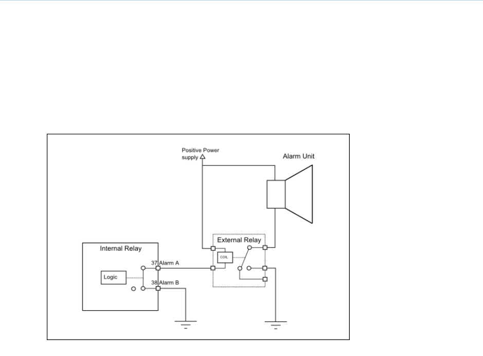
10.1.3.5 Alarm Relay Output
The Alarm relay is a normally open earth free relay contact, provided as an independent and simple
method for triggering an external alarm. The alarm relay is deactivated upon acknowledgment of an
alarm, either internally on the display unit, or by an externally provided ACK sentence. If the
Transponder power is lost, and the Alarm relay has power, the alarm will be triggered. In this case, the
only way to deactivate the Alarm is to power the Transponder unit or disconnect the power source of
the Alarm relay.
Figure 10-1 Typical Alarm connection
TR-8000 Operator and Installation Manual 82
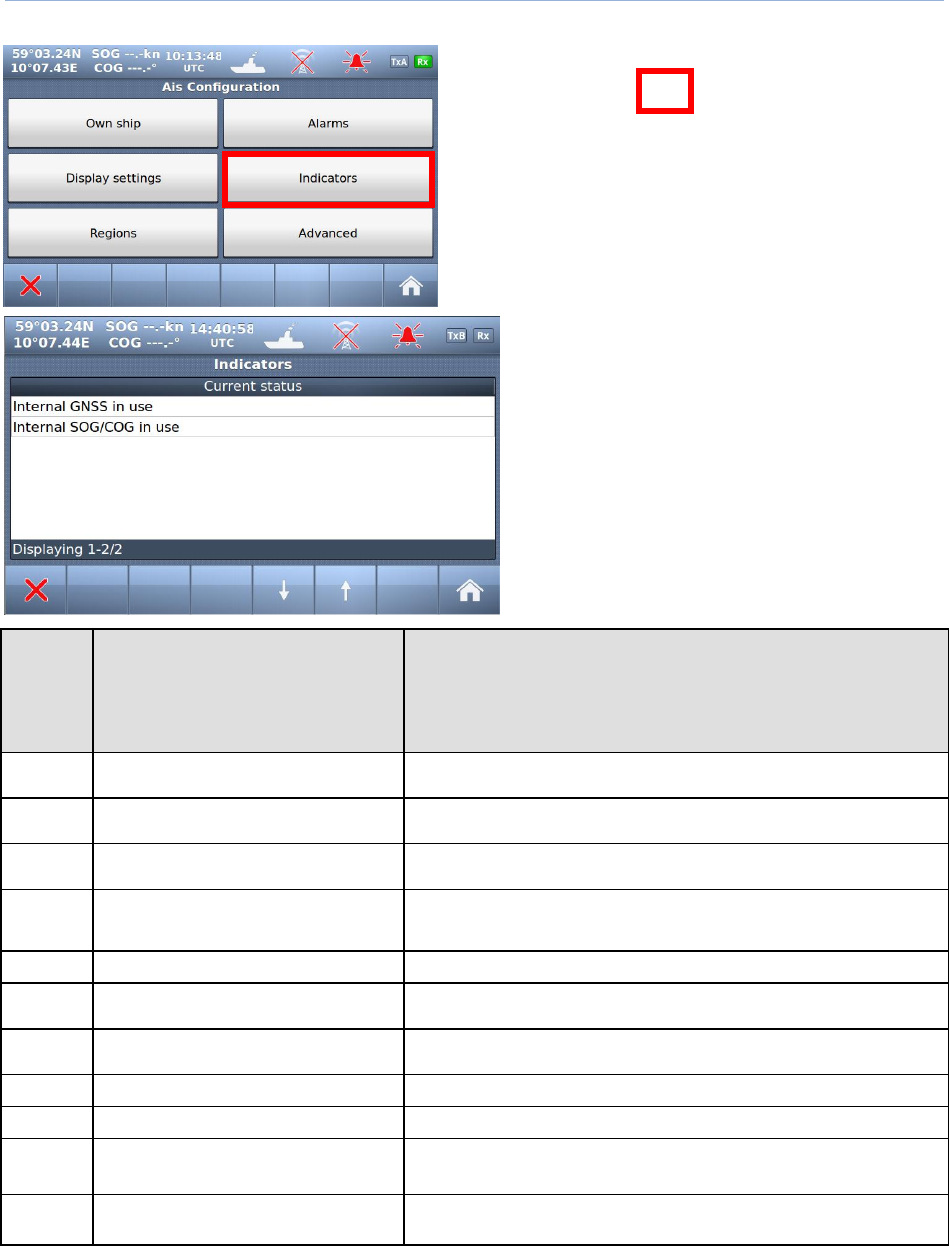
10.1.4 Indicators
Red square shows
button selected to get to next menu
The indicators show information about where
sensor data are collected, valid Heading etc.
This list may be used if troubleshooting of the
sensors is needed. The available messages are
as given in .
Text
Identifier
“Indicators”
(Shown on Display unit and
also sent as text message to
ECS/ECDIS or other equipment
connected to PI port)
Description
021
External DGNSS in use
DGNSS is normally the same as DGPS, which indicates external type of
such sensor is in use
022
External GNSS in use
GNSS is normally the same as GPS, which indicates external type of such
sensor is in use
023
Internal DGNSS in use (beacon)
Internal DGNSS (DGPS) (beacon) in use indicates a DGNSS beacon
receiver is connected and transmit valid data to TR-8000
024
Internal DGNSS in use (Message 17)
Internal DGNSS (DGPS) (Message 17) in use indicates Differential
correction data is sent from an AIS Base Station to this TR -8000
transponder
025
Internal GNSS in use
The inbuilt GNSS (GPS) receiver is in use
027
External SOG/ COG in use
SOG (Speed Over Ground)/ COG (Course Over Ground) from external
GNSS(GPS) device is in use
028
Internal SOG/ COG in use
SOG (Speed Over Ground)/ COG (Course Over Ground) from internal
GNSS(GPS) device is in use
031
Heading valid
True Heading is received from either an external Gyro or Satelitte compass
033
(ROT) Rate of Turn Indicator in use
ROT received from external sensor: TI (Turn Indicator)
034
Other ROT source in use
No TI(Turn Indicator) from external sensor,
ROT(Rate of Turn) value is calculated from HDT internally
036
Channel management parameters
changed
If either “Region setting” is applied manually or from msg received
from AIS Base Station, this indicator will be shown.
Table 3: Indicators.
TR-8000 Operator and Installation Manual 83
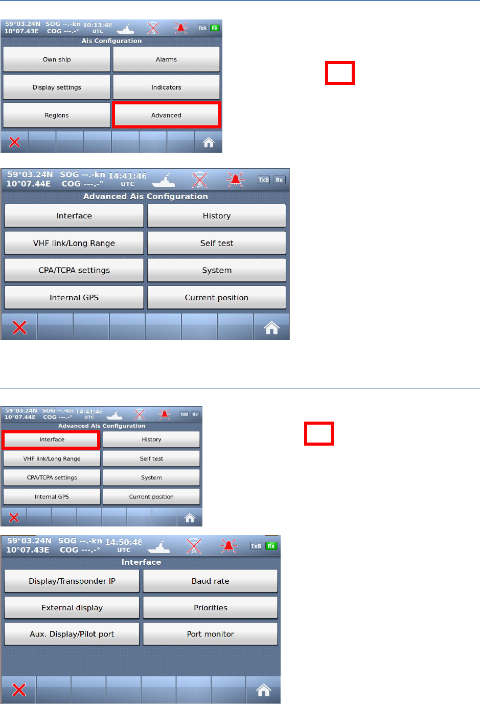
10.2 Advanced Menu
Red square shows
button selected to get to next menu
The Advanced Menu is intended for
use during setup and maintenance of
the TR-8000 AIS system. Some of the
menus are write protected by
password, but all parameters are
readable to all users for inspection.
10.2.1 Interface
Red square shows
button selected to get to next menu
In the “Interface” menu, the parameters
shown on the left picture can be
configured.
TR-8000 Operator and Installation Manual 84
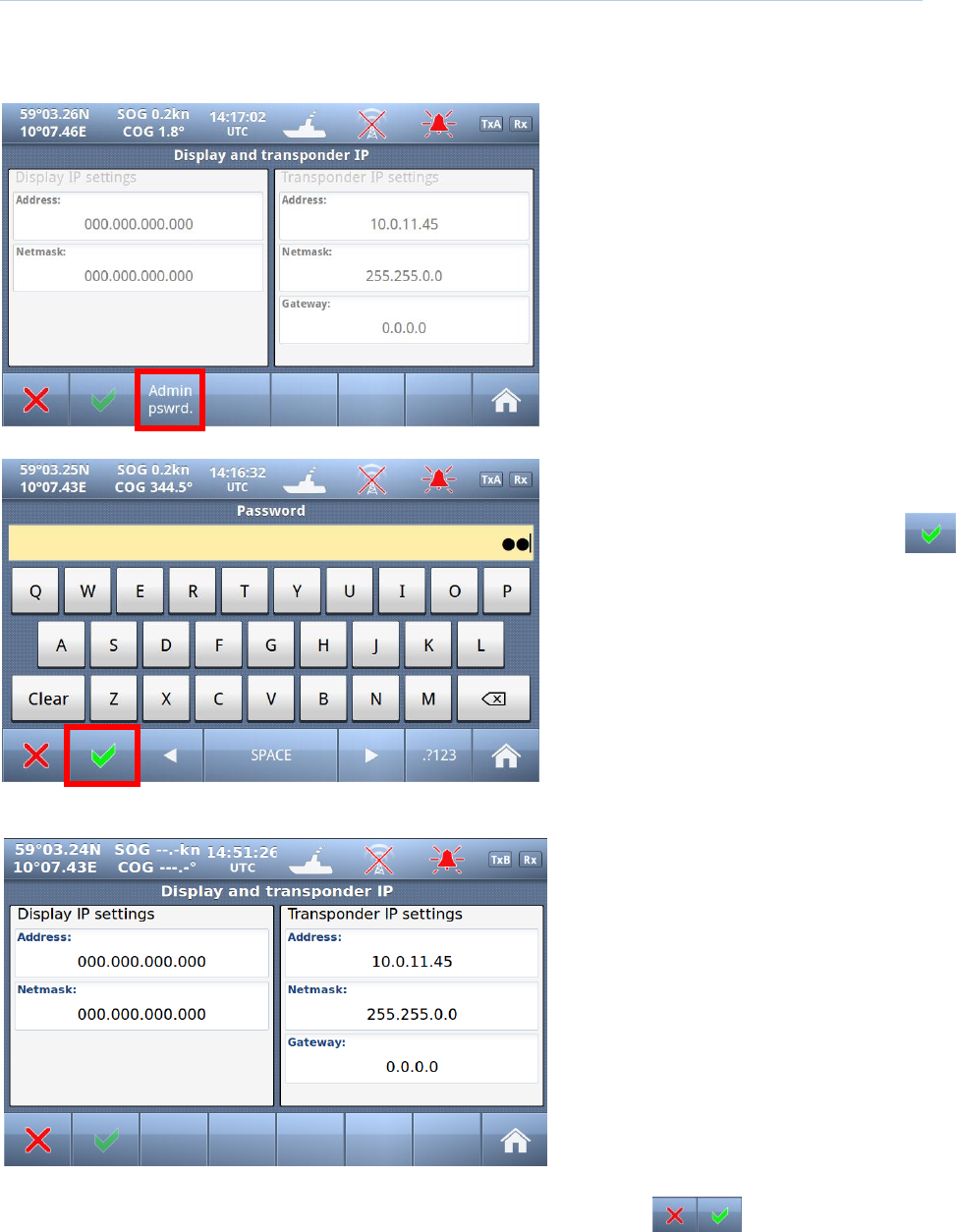
10.2.1.1 Display/ Transponder IP
NOTE! Since the TR-8000 uses Ethernet between transponder unit and display, an IP addresses must be
correctly configured
All parameters /buttons are “grayed out”
as they are not accessible without
“Admin Pswrd”
When “Admin pswrd” button is selected,
the following window appear:
Input the “Admin Password” (SE) into the
field and press the “Confirm” button:
Then it is possible to access all fields and configure IP correctly:
Default values are:
Display:
Adress: 10.0.0.11
Mask: 255.255.0.0
Transponder:
Adress: 10.0.0.10
Mask: 255.255.0.0
Gateway: 0.0.0.0
(Gateway is only used if Transponder communicates
through a router that performs NAT (Network Address
Translation). Then the Router address must be written
here as “Gateway”)
And when configuration is finished either of “Return” or “Confirm” buttons will bring
you back to last menu.
TR-8000 Operator and Installation Manual 85
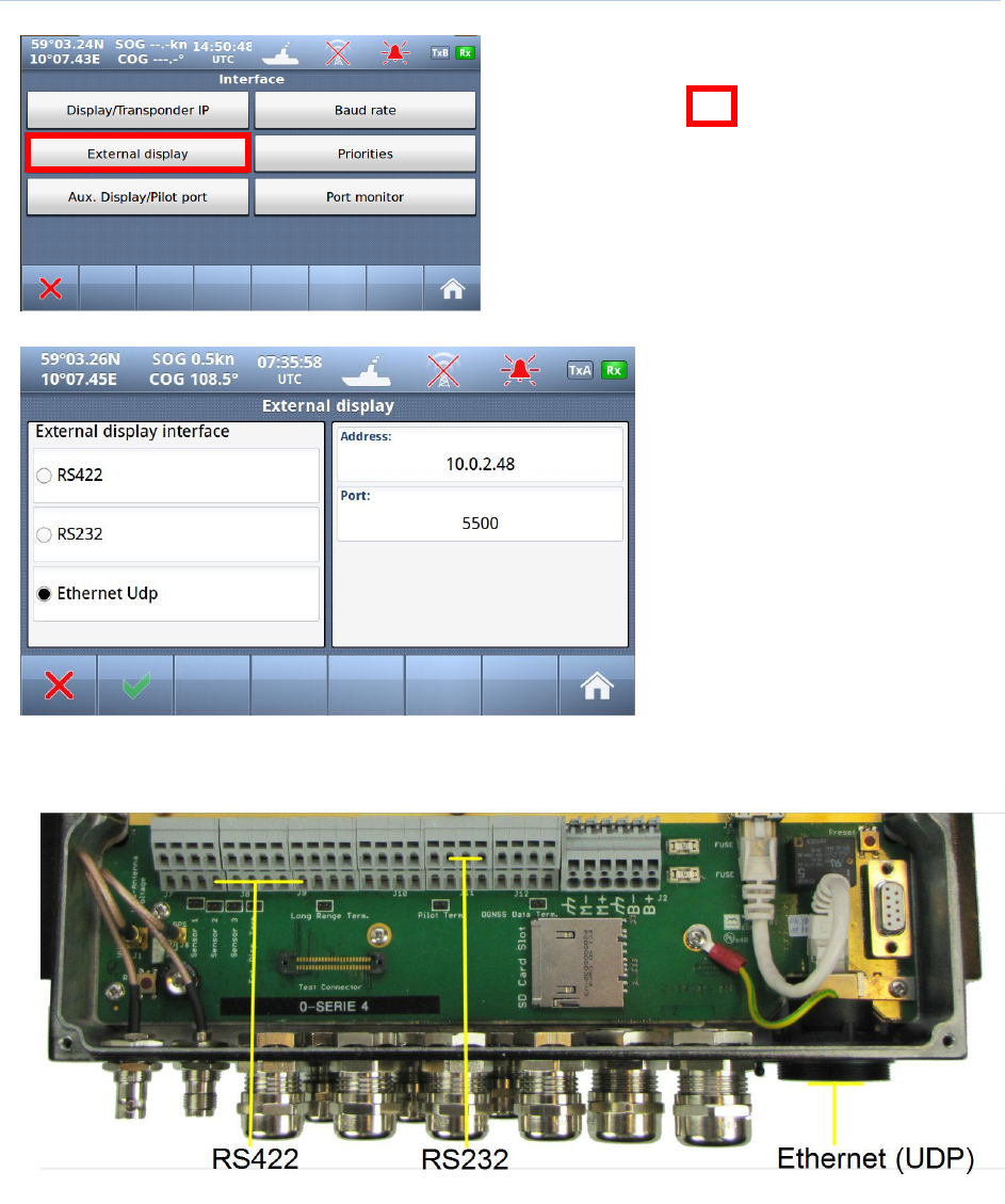
10.2.1.2 External display
Red square shows
button selected to get to next menu
The TR-8000 support three
different methods of connecting an
external Display.
If Ethernet is used, the External
Display should be connected
through an external Ethernet
switch since the TR-8000 Display
unit is already connected to this
connector
see also chapter 8.3.1.5 which describes the External Display physical connections
TR-8000 Operator and Installation Manual 86
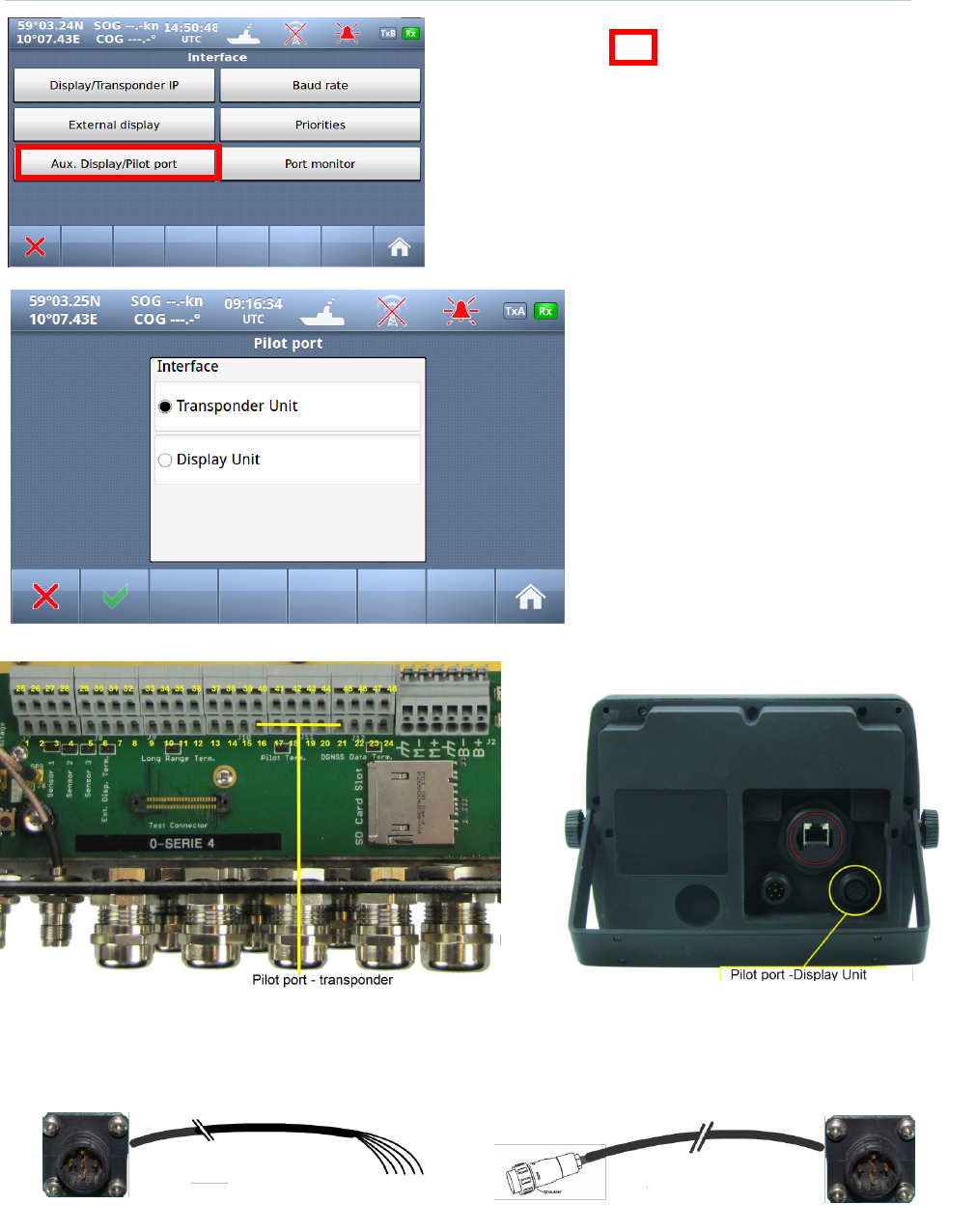
10.2.1.3 Aux. Display/Pilot Port
Red square shows
button selected to get to next menu
The TR-8000 has the flexibility of
either connecting the Pilot port
outlet to the Transponder unit or the
Display unit, and therefore you may
select which of the two option you
want to use.
Below pictures shows where the
physical connections are made.
Figure 10-2 Pilot port connection, TR-8000 Transponder unit
Figure 10-3 Pilot port connection, TR-8000 Display unit (rear
)
Figure 10-4 Pilot port cable, Display unit
Figure 10-5 Pilot port cable, Transponder unit
TR-8000 Operator and Installation Manual 87
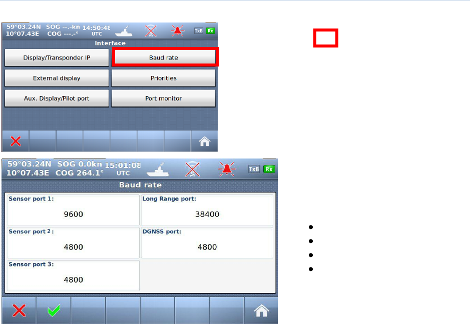
10.2.1.4 Baud rate
Red square shows
button selected to get to next menu
Press one of the 5 Port buttons to
change the baud rate of that port.
It will then jump between the legal
options:
4800 (default: Sensor)
9600
19200
38400 (default: Long Range)
TR-8000 Operator and Installation Manual 88
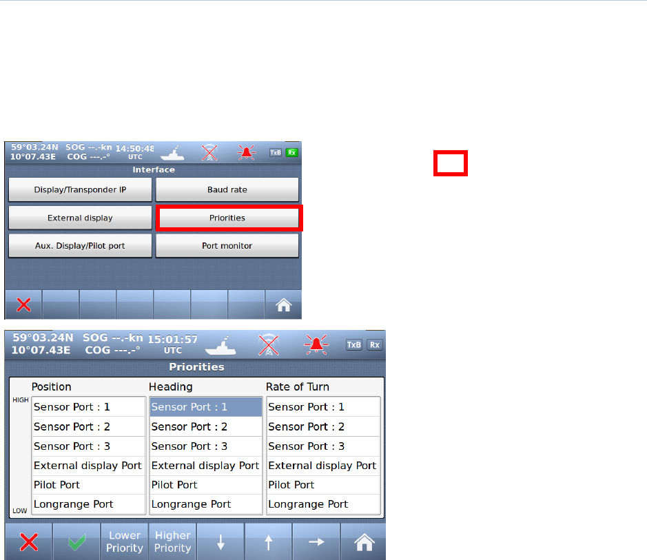
10.2.1.5 Priorities
From this menu the priorities for the different sensor measurements can be set individually.
I.e if the unit receives Heading data from two different sources, the settings here specify what data
source to be used.
In order to navigate through the different sensors, administrator password is required.
Red square shows
button selected to get to next menu
Priorities of Position, Heading and Rate
Of Turn can be configured in this
window
Select which “ Port” will have lower or
higher priority.
TR-8000 Operator and Installation Manual 89
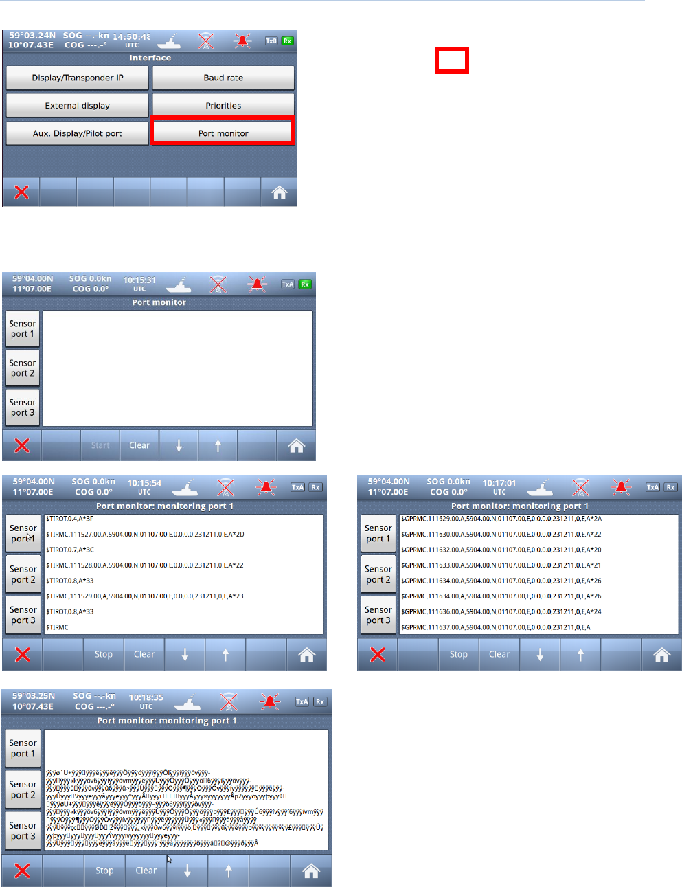
10.2.1.6 Port Monitor
Red square shows
button selected to get to next menu
“Port monitor” is an important feature in TR-8000 Display Unit which can help troubleshooting
connection issues with different sensors. The “Port monitor” acts as a Terminal window, showing raw
data received on a sensor, similar to Windows “Hyperterminal”
First select which “Sensor port” you want to
“listen” to
And if a Sensor is connected it could look similar to
these:
The two screenshots above shows Sensor
data which are most probably OK, while left
screenshot shows corrupt data from incorrectly
connected sensor (Polarity of signals are
incorrect)
TR-8000 Operator and Installation Manual 90
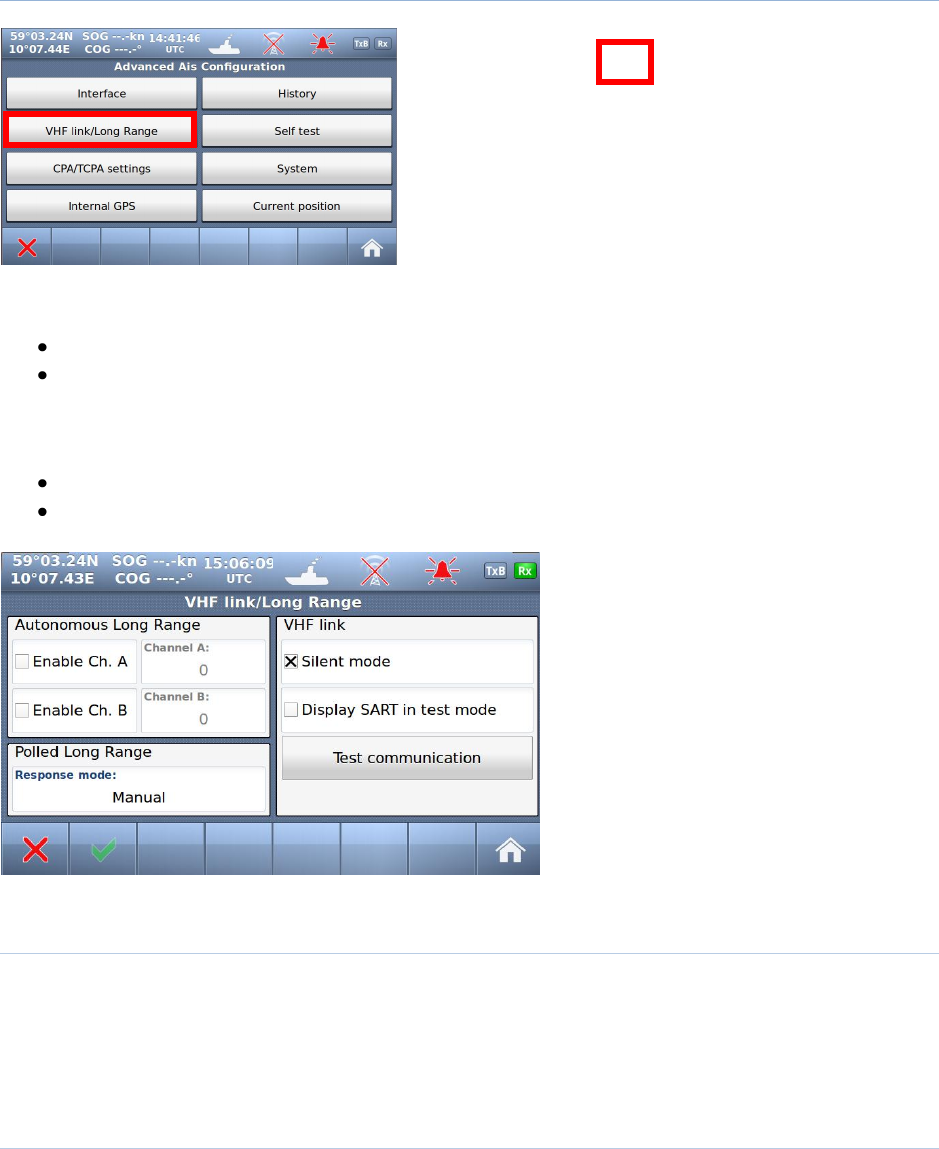
10.2.2 VHF link/Long Range
Red square shows
button selected to get to next menu
In this menu, configuration of
Long Range
VHF Link (Silent ON/OFF)
can be done, In addition to:
Test VHF link communication
Display AIS-SART when such equipment are tested
10.2.2.1 Autonomous Long Range
Long Range Broadcast Channel A and B are used for broadcasting positions and ship data to a
satellite system. Base Stations are able to temporarily disable the Long Range broadcast functionality of
the AIS. The Long Range Broadcast may also be disabled manually by administrator.
10.2.2.2 Polled Long Range
The Polled Long Range system can be configured to reply automatically or wait for
acknowledgement from the user. An indication of received LR messages is displayed for the user in
either case.
TR-8000 Operator and Installation Manual 91
10.2.2.3 Silent mode
The silent mode is a special mode for travelling in areas where the transmission of own position impose
risk to the user. When active, no signals are sent from the Transponder unit, but the user is still able to
receive information from other vessels.
If the Silent Mode is active for more than 15 minutes, the event is logged in the History Log.
CAUTION: The Silent Mode disables the AIS Transmitter functionality and will make the Vessel
invisible on the AIS system and impose a risk to other and own vessels.
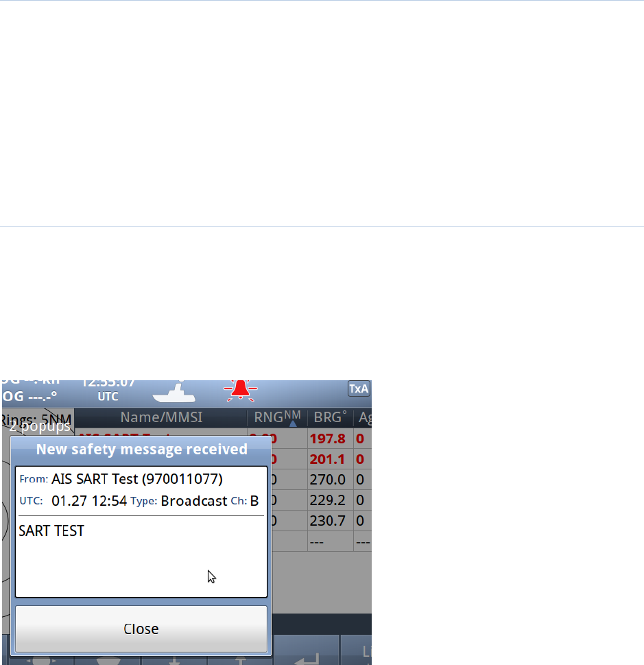
10.2.2.4 Display SART in TEST mode
When AIS-SART was introduced as alternative to traditional Radar SART in 2011, it was obvious that
testing such equipment could lead to much “noise” on nearby ships AIS Transponders and ECS/ECDIS as
this AIS-SART icon/text message would pop up on all nearby vessels within VHF range (5-40 nautical
miles). Therefore, revisions in the AIS standards were made so the person who wants to test the AIS on-
board the ship, must first activate this menu item before it will be shown on the vessels AIS and
ECS/ECDIS or Chart Plotter.
Example showing “Display SART in
test mode” and Popup received to be
acknowledged by pressing “Close” button
PS! Observe that here are “2 popups”
received from 2 different AIS-SARTs and
each “popup” must be acknowledged.
Also observe that AIS-SARTs are displayed
in top of the list in the background, and
with RED color.
TR-8000 Operator and Installation Manual 92
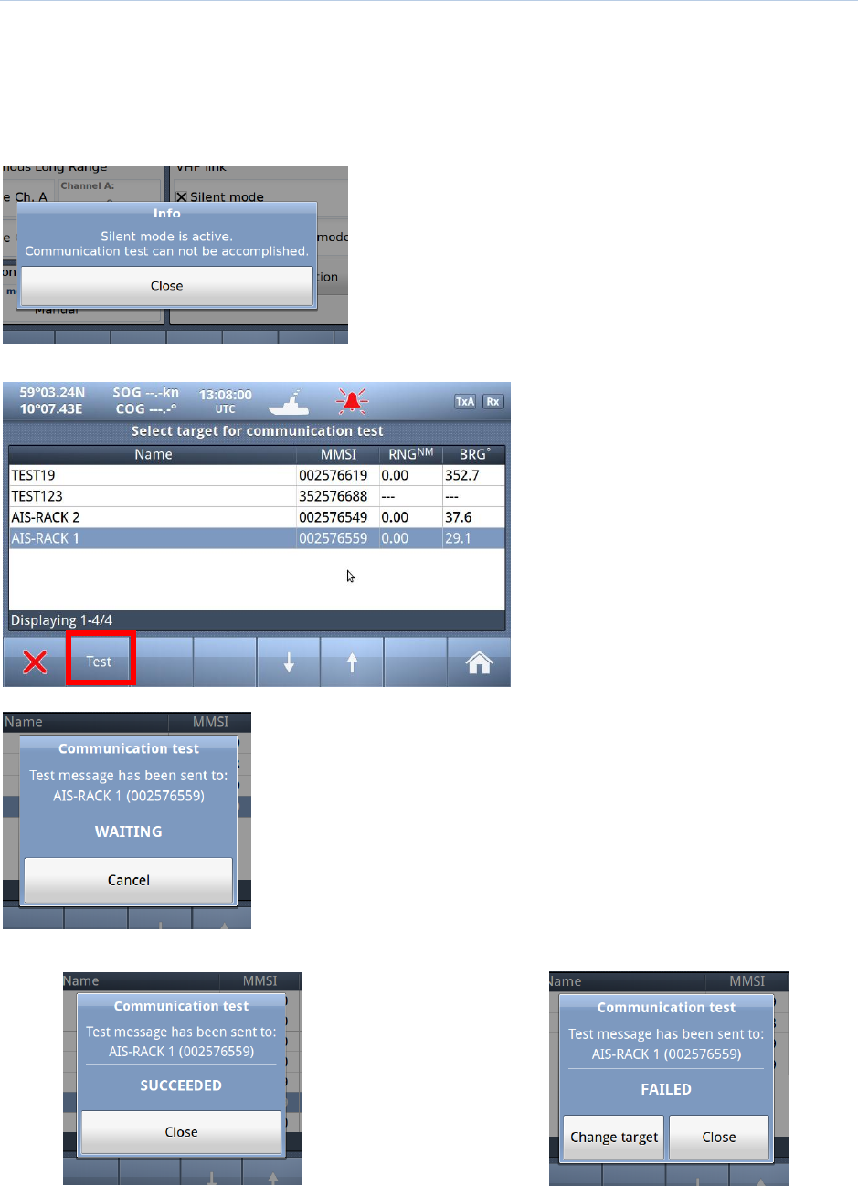
10.2.2.5 Test Communication
The Communications Test is used to test the VHF communication by transmitting a request for an
acknowledgement to another ship. The target is automatically selected by the Display Unit, but the user
can choose to select another target as long as the target is a Class A AIS transponder. If the
Acknowledgment is not received within 10 seconds, the Communications Test has failed and the user
should optionally retry with another target.
If the TR-8000 is in “Silent mode”, it is not possible to
perform this test:
If not, we can continue with the test:
Step #1: Select Target
Step #2: Press “Test”
Step #3: Wait until test finished
Success: or Failure:
If the TEST fails, we can select another target and redo the test
TR-8000 Operator and Installation Manual 93
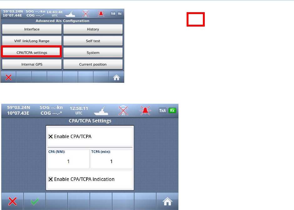
10.2.3 CPA/TCPA settings
Red square shows
button selected to get to next menu
The CPA (Closest Point of Approach)
and TCPA (Time to Closest Point of
approach) range for which you want to
be alerted of AIS targets on a possible
collision course with you needs to be
set here. You may also disable the
CPA/TCPA functionality manually. How
the user is alerted is also specified in
this menu.
TR-8000 Operator and Installation Manual 94
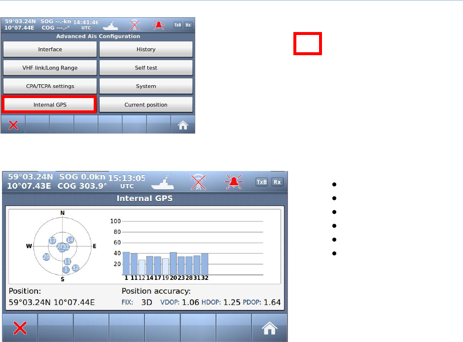
10.2.4 Internal GPS
Red square shows
button selected to get to next menu
It is possible to inspect the functionality of the internal GPS receiver by the following parameters:
Satellites in view
Signal strength
Position
Pos. accuracy
Precision
Differential mode
TR-8000 Operator and Installation Manual 95
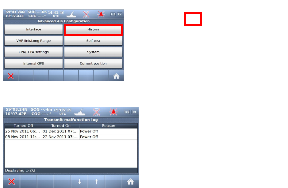
10.2.5 History Log
Red square shows
button selected to get to next menu
If the transmitter functionality of the transponder stops functioning for more than 15 minutes, this
is logged as an event in the History Log.
TR-8000 Operator and Installation Manual 96
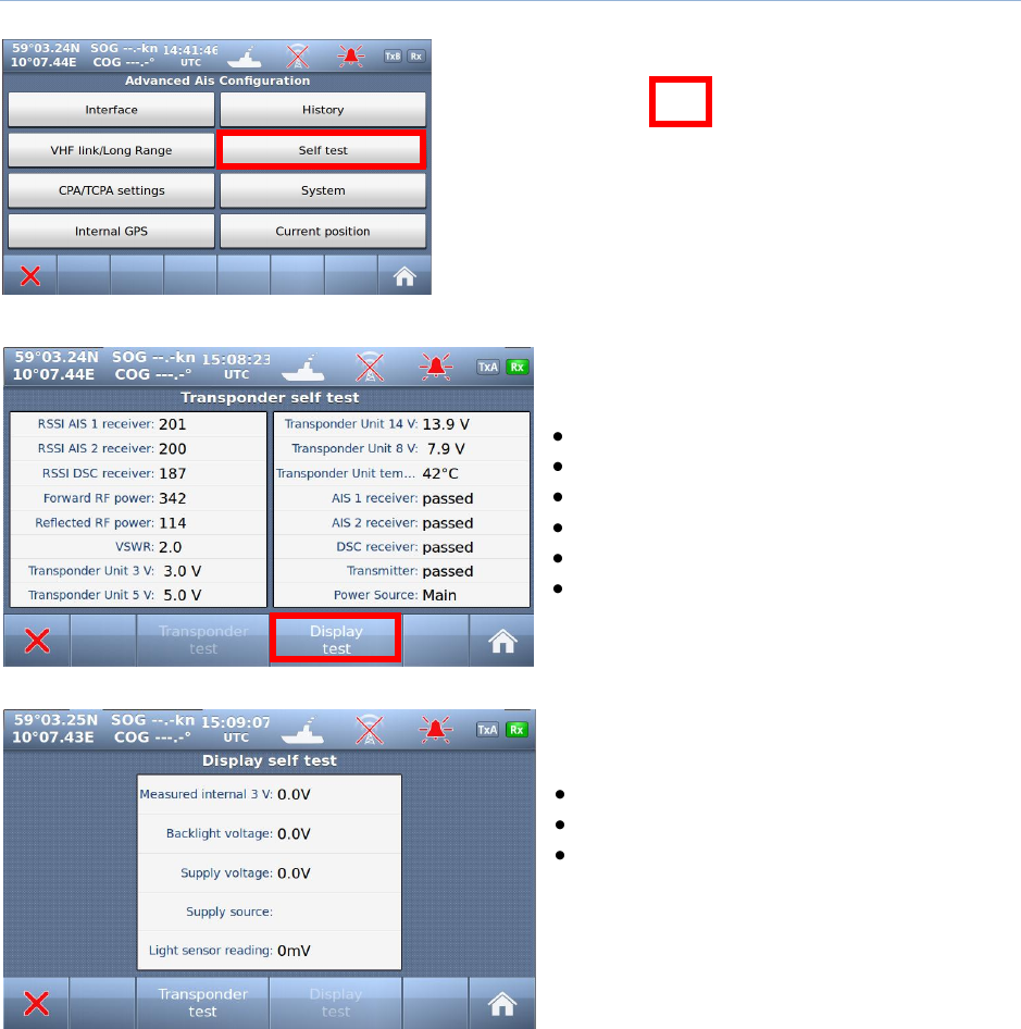
10.2.6 Self Test
Red square shows
button selected to get to next menu
The “Self Test” consist of two different tests, a “Transponder self test” and a “Display self test”:
“Transponder self test” measures values of:
Signal strength (RSSI.. 0-255)
RF Power (Forward+ Reflected :0-512)
Antenna matching (VSWR)
Voltages ( 3, 5, 8 and 14v)
Receivers status
Transmitter status
Power source (Main, Backup)
When “Display test” is selected, this window is
shown with measurement:
Voltages
Supply source (Power source)
Light sensor reading (If automatic
display adjustment are activated [option])
TR-8000 Operator and Installation Manual 97
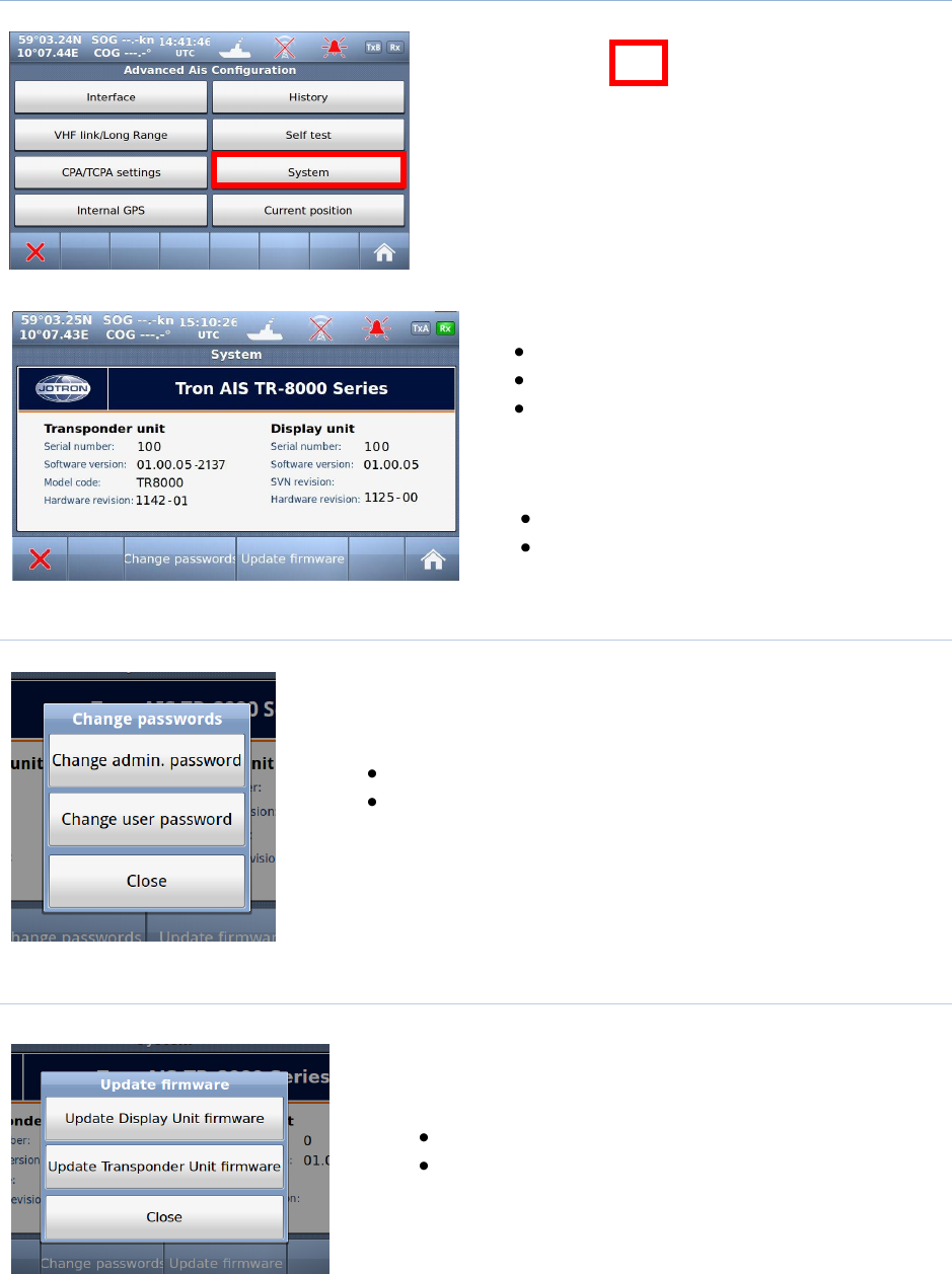
10.2.7 System
Red square shows
button selected to get to next menu
In this window you can read information about :
Serial number
Software
Hardware
of both Display and Transponder unit
In addition you may select the buttons:
Change password
Update firmware
10.2.7.1 Change password
If you select “Change password”, you can select between
Admin password
User password
NOTE: You must have access to “Admin password” to change the “User
password”
10.2.7.2 Update Firmware
If you select “Update firmware”, you can select between
Display unit firmware
Transponder unit firmware
NOTE: Update of Firmware shall only be done by Jotron trained
dealers, distributors & service agents.
TR-8000 Operator and Installation Manual 98
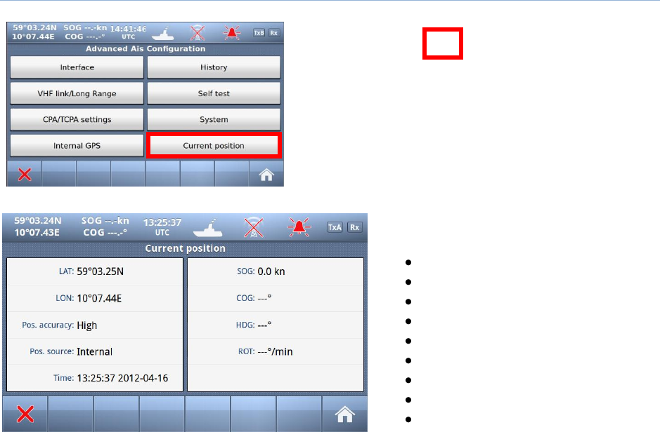
10.2.8 Current position
Red square shows
button selected to get to next menu
The “Current position” will show
information about:
Latitude
Longitude
Pos Accuracy (High/Low)
Pos Source (Internal/External)
Time & Date
SOG (Speed over Ground)
COG (Course Over Ground))
HDG (Heading)
ROT (Rate Of Turn)

TR-8000 Operator and Installation Manual 99
11 Menu tree
Configuration menu
Own Ship data (Name, MMSI, IMO number, Antenna Position, Type of Vessel)
Display Settings (Sleeping targets)
Regions
o Add region
o View regions
Alarms
Indicators
Advanced
o Interface
Display/Transponder IP
External Display
Aux. Display/Pilot Port
Baud rate
Priorities
Port Monitor (monitor sensor connections)
o VHF link / Long Range
o CPA/TCPA settings
o Internal GPS
o History
o Self Test
o System (System information, serial no. and revisions)
Change Passwords
Update firmware
o Current Position
Safety Message Menu
Toggle between sent and received messages
Write New message
Select message in list (up and down arrows)
Resend a selected Sent message (if any) or reply on a selected Received message (if any)
Display options
Day / Night mode
Dimming
Voyage Data
Configuration of Navigation Status, Destination, ETA, Draught, Cargo category and number of
Persons aboard.

TR-8000 Operator and Installation Manual 100
12 List of VHF Channels
Channel
no.
Frequency
Channel
no.
Frequency
Channel
no.
Frequency
Channel
no.
Frequency
6
156.3000
1021
157.0500
1279
156.9775
2219
161.5625
8
156.4000
1022
157.1000
1280
157.0375
2220
161.6125
9
156.4500
1023
157.1500
1281
157.0875
2221
161.6625
10
156.5000
1024
157.2000
1282
157.1375
2222
161.7125
11
156.5500
1025
157.2500
1283
157.1875
2223
161.7625
12
156.6000
1026
157.3000
1284
157.2375
2224
161.8125
13
156.6500
1027
157.3500
1285
157.2875
2225
161.8625
14
156.7000
1028
157.4000
1286
157.3375
2226
161.9125
15
156.7500
1060
156.0250
1287
158.3875
2227
161.9625
16
156.8000
1061
156.0750
2001
160.6500
2228
162.0125
17
156.8500
1062
156.1250
2002
160.7000
2260
160.6375
67
156.3750
1063
156.1750
2003
160.7500
2261
160.6875
68
156.4250
1064
156.2250
2004
160.8000
2262
160.7375
69
156.4750
1065
156.2750
2005
160.8500
2263
160.7875
70
156.5250
1066
156.3250
2007
160.9500
2264
160.8375
71
156.5750
1078
156.9250
2018
161.5000
2265
160.8875
72
156.6250
1079
156.9750
2019
161.5500
2266
160.9375
73
156.6750
1080
157.0250
2020
161.6000
2278
161.5375
74
156.7250
1081
157.0750
2021
161.6500
2279
161.5775
75
156.7750
1082
157.1250
2022
161.7000
2280
161.6375
76
156.8250
1083
157.1750
2023
161.7500
2281
161.6875
77
156.8750
1084
157.2250
2024
161.8000
2282
161.7375
208
156.4125
1085
157.2750
2025
161.8500
2283
161.7875
209
156.4625
1086
157.3250
2026
161.9000
2284
161.8375
210
156.5125
1087
157.3750
2027
161.9500
2285
161.8875
211
156.5625
1088
157.4250
2028
162.0000
2286
161.9375
212
156.6125
1201
156.0625
2060
160.6250
2287
161.9875
213
156.6625
1202
156.1125
2061
160.6750
214
156.7125
1203
156.1625
2062
160.7250
215
156.7625
1204
156.2125
2063
160.7750
216
156.8125
1205
156.2625
2064
160.8250
217
156.8625
1206
156.3125
2065
160.8750
267
156.3875
1207
156.3625
2066
160.9250
268
156.4375
1218
156.9125
2078
161.5250
269
156.4875
1219
156.9625
2079
161.5750
270
156.5375
1220
157.0125
2080
161.6250
271
156.5875
1221
157.0625
2081
161.6750
272
156.6375
1222
157.1125
2082
161.7250
273
156.6875
1223
157.1625
2083
161.7750
274
156.7375
1224
157.2125
2084
161.8250
275
156.7875
1225
157.2625
2085
161.8750
276
156.8375
1226
157.3125
2086
161.9250
277
156.8875
1227
157.3625
2087
161.9750
1001
156.0500
1228
157.4125
2088
162.0250
1002
156.1000
1260
156.0375
2201
160.6625
1003
156.1500
1261
156.0875
2202
160.7125
1004
156.2000
1262
156.1375
2203
160.7625
1005
156.2500
1263
156.1875
2204
160.8125
1007
156.3500
1264
156.2375
2205
160.8625
1018
156.9000
1265
156.2875
2206
160.9125
1019
156.9500
1266
156.3375
2207
160.9625
1020
157.0000
1278
156.9375
2218
161.5125
Channel 2087 = Channel 87B Channel 2088 = Channel 88B

TR-8000 Operator and Installation Manual 101
13 Complied Standards
The TR-8000 AIS system complies with the following standards:
IMO Resolution MSC.694(17) – General Requirements for Shipborne Radio Equipment forming part of
the Global Maritime Distress and Safety System (GMDSS) and for Electronic Navigational Aids
IMO Resolution MSC.74(69) Annex 3 Recommendation on performance standards for AIS
IMO Resolution MSC.191(79) – Performance standards for the presentation of navigation related
information on shipborne navigational displays
ITU-R M.1371-4 (Class A), 2010 – Technical characteristics for an automatic identification system using
time-division multiple access in the VHF maritime mobile band
ITU-R M.825-3, 1998 - Characteristics of a transponder system using digital selective calling techniques
for use with vessel traffic services and ship-to-ship identification
ITU-R M.1084-4 – Interim solutions for improved efficiency in the use of the band 156-174 MHz by
stations in the maritime band
IEC 61993-2,2001 - Maritime navigation and radio communication equipment and systems –
Automatic Identification Systems (AIS), Part 2: Class A ship borne equipment of the universal automatic
identification system (AIS) – Operational and performance requirements, methods of test and required
results
IEC 61108-1 Ed.2, 2003 – Maritime navigation and radio communication equipment and systems –
Global navigation satellite systems (GNSS)
IEC 62288 Ed.1, 2008 – Maritime navigation and radio communication equipment and systems –
Presentation of navigation-related information on shipborne navigational displays – General
requirements, methods of testing and required test results
IEC 61162-1 Ed.4, 2010 - Maritime navigation and radio communication equipment and systems –
Digital interfaces – Part 1: Single talker and multiple listeners
IEC 61162-2 Ed.1, 1998 - Maritime navigation and radio communication equipment and systems –
Digital interfaces – Part 2: Single talker and multiple listeners, high-speed transmission
IEC 60945 Ed.4, 2002 incl. Corr.1, 2008 – Maritime navigation and radio communication equipment
and systems – General requirements – Method of testing and required test results
TR-8000 Operator and Installation Manual 102
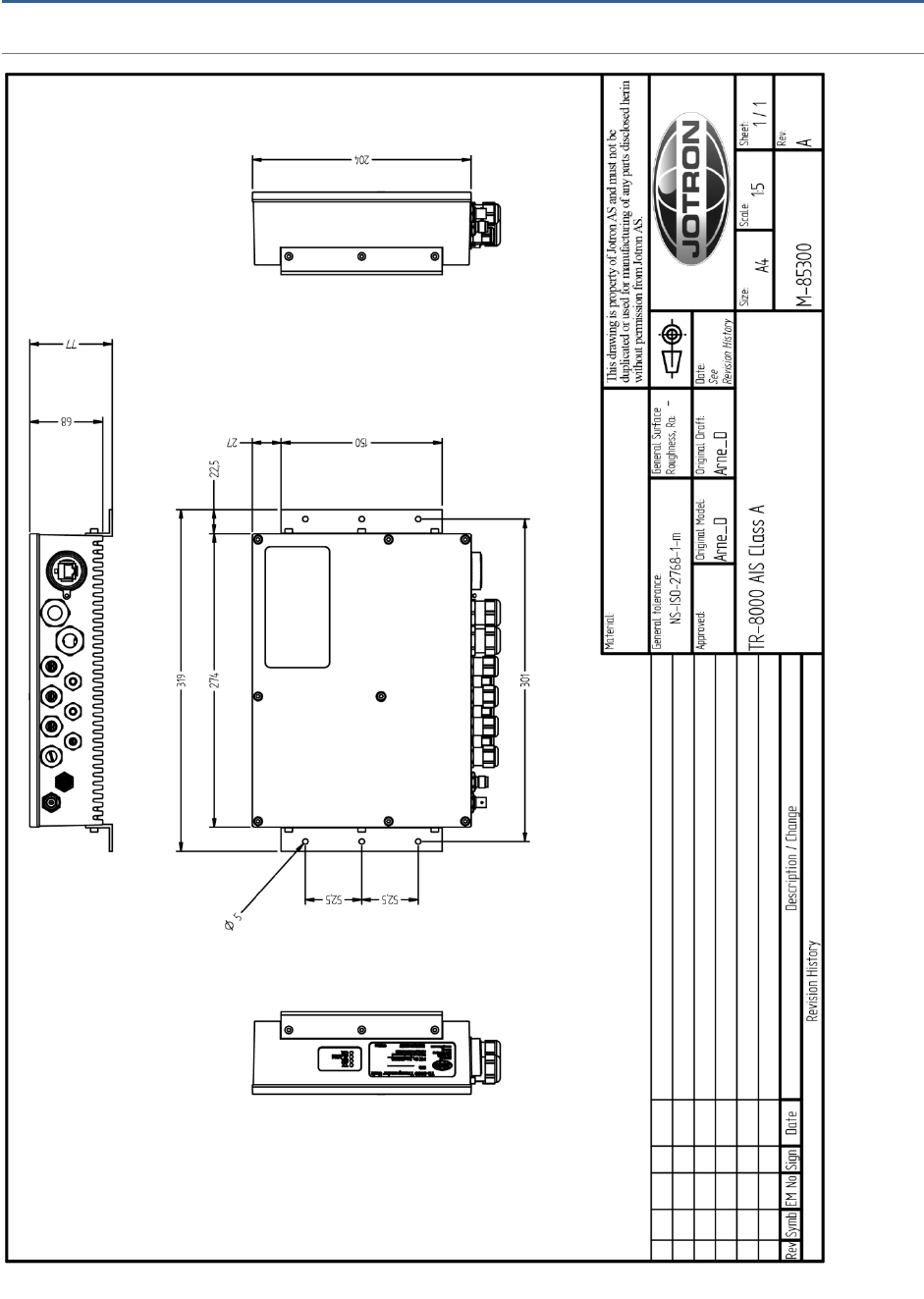
14 Outline Drawings
14.1 TR-8000 Transponder Unit
Figure 14-1 TR-8000 Transponder Unit- mechanical dimensions

TR-8000 Operator and Installation Manual 103
14.2 TR-8000 Display Unit, Desktop or Overhead mount
Figure 14-2 TR-8000 Display Unit- Mechanical Dimensions
TR-8000 Operator and Installation Manual 104
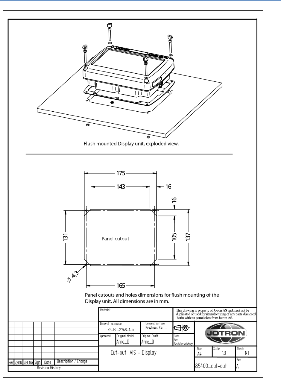
14.3 TR-8000 Display Unit, Flush/Panel mount
Figure 14-3 TR-8000 Display Unit - Flush Mount Cutout dimensions
TR-8000 Operator and Installation Manual 105
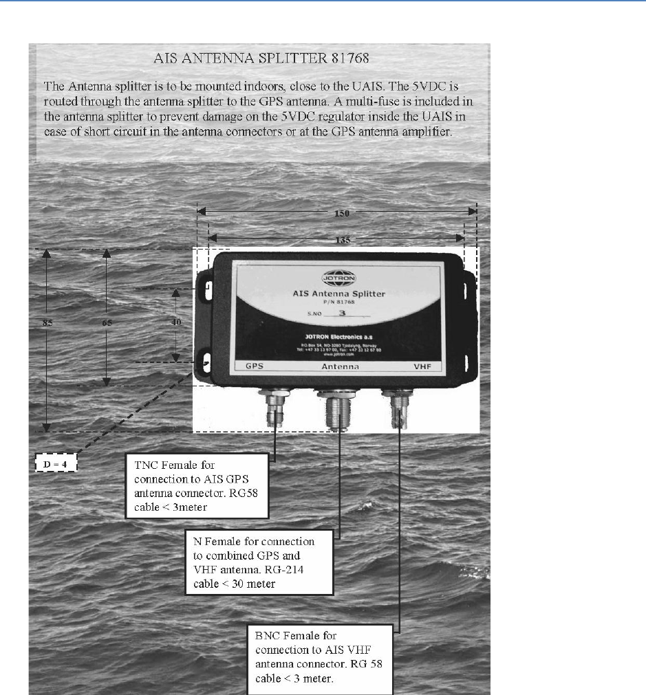
14.4 AIS Antenna Splitter
Figure 14-4 AIS Antenna Splitter Datasheet
TR-8000 Operator and Installation Manual 106
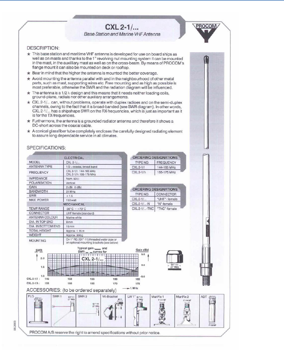
14.5 Procom CXL 2-1LW/h Maritime VHF Antenna
Figure 14-5 Procom CXL 2-1 VHF Antenna datasheet
TR-8000 Operator and Installation Manual 107
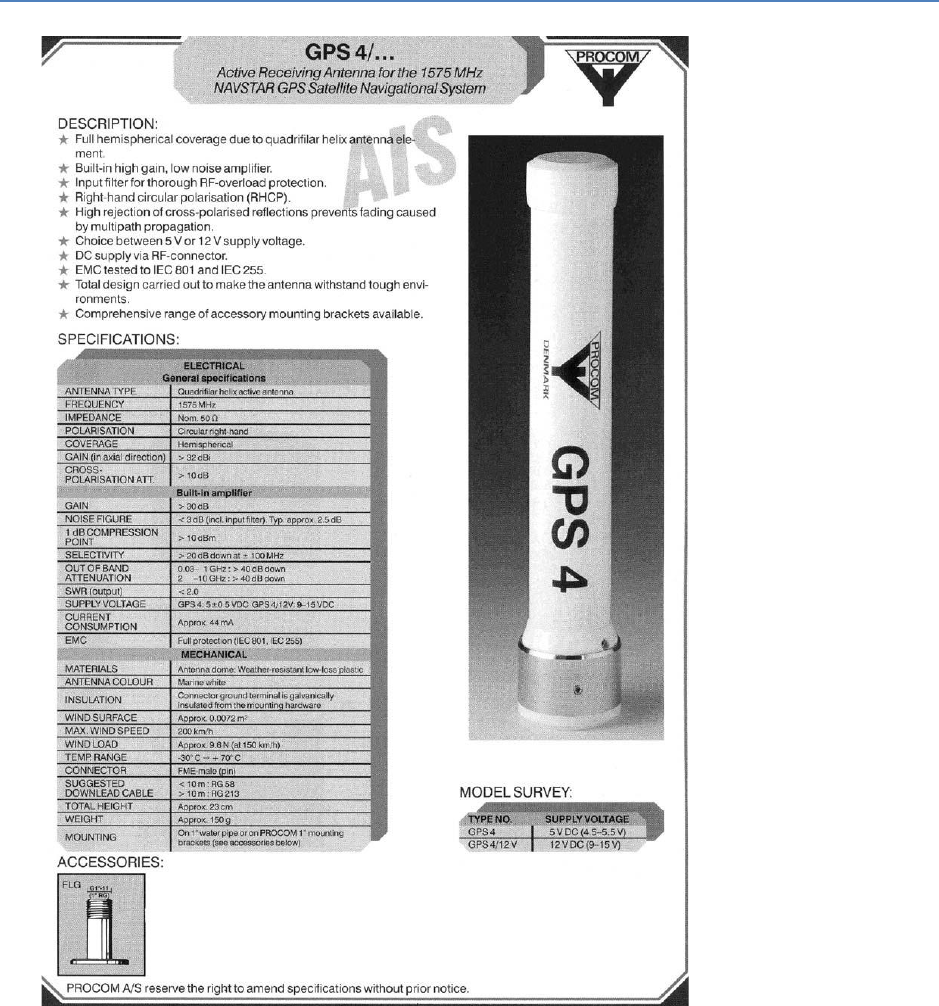
14.6 Procom GPS 4 Antenna
Figure 14-6 Procom GPS4 Antenna datasheet

TR-8000 Operator and Installation Manual 108
14.7 SANAV – GPS Marine Antenna
Figure 14-7 Sanav SA-200 GPS Antenna
GPS Marine Antenna with Low Noise Amplifier
SA-200 is designed for the Marine Vessels mast or tall buildings that require long extra cables (up to
50 meters) without signal constraint to the GPS receivers.
MODEL: SA-200
Overview
SA-200 is the integration of the high performance GPS patch antenna and a state-of-the-art low
noise amplifier into an extremely compact/fully waterproof enclosure and when connected to a GPS
receiver with +5VDC antenna power it can provide excellent antenna signal amplification and out-
band filtering with rejection for that receiver.
Specification
Physical Constructions:
Constructions:
Polycarbonate radome enclosure (top & bottom base with rubber O-ring
inbetween) Center feeds TNC connector for antenna output
Dimensions:
4.5" in diameter & 2.9" in height
Weight:
220 grams (without cable)
Standard Mounting:
External flagpole mount (11cm-height threaded mast), an optional accessory kit
Optional mounting plate:
1. Cabin roof-mount with stainless steel base & shaft
2. Rail side mount with stainless rod
TR-8000 Operator and Installation Manual 109
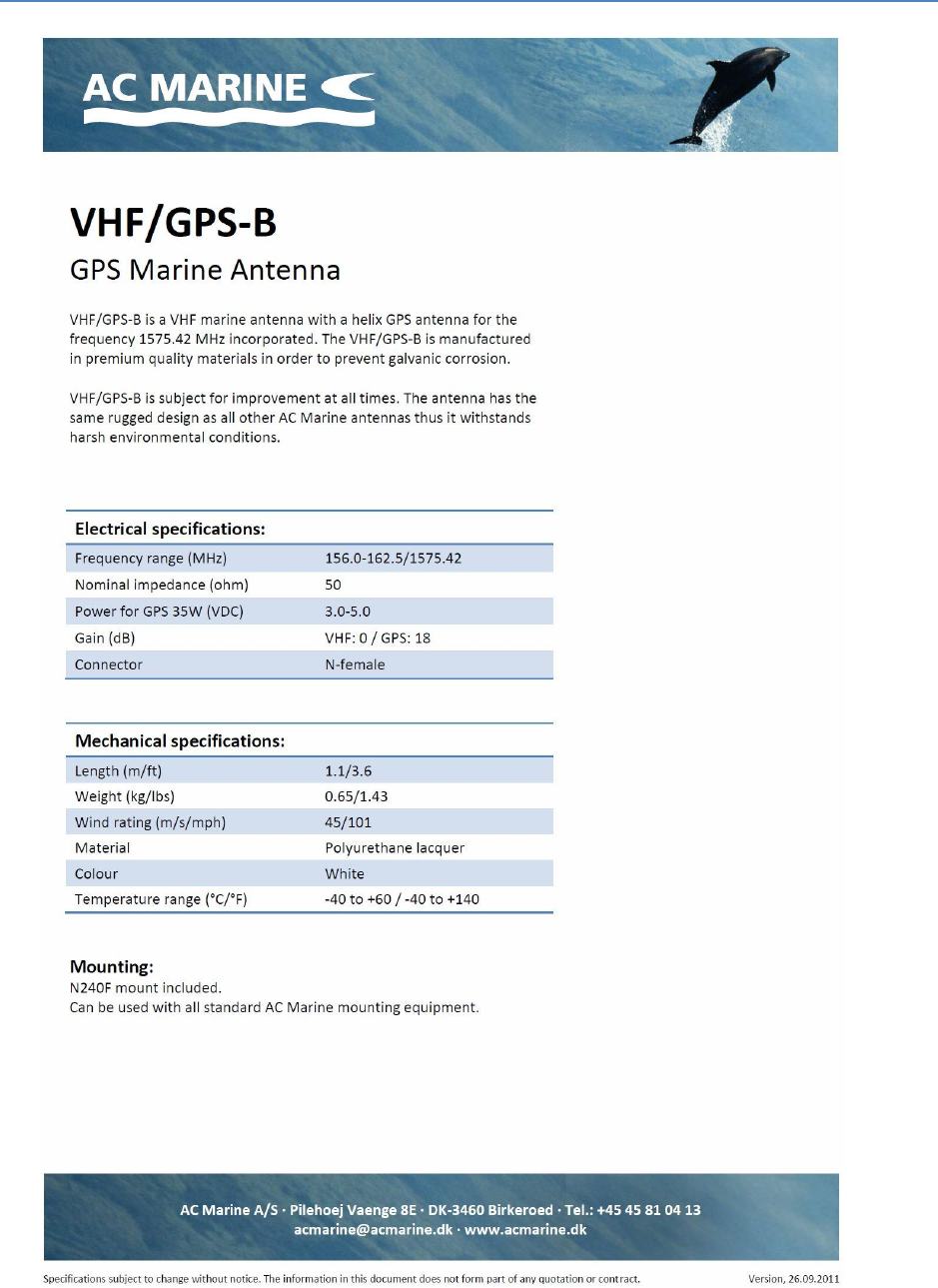
14.8 AC Marine VHF/GPS-B
Figure 14-8 AC Marine VHF/GPS-B Combined Antenna datasheet

TR-8000 Operator and Installation Manual 110
15 Abbreviations and Definitions
ACK Acknowledge
AIS Automatic Identification System - A shipborne broadcast transponder system in which ships
continually transmit their position, course, speed and other data to other nearby ships and
shoreline authorities on a common VHF radio channel.
AIS-SART Automatic Identification System-Search And Rescue Transponder
AtoN Aid to Navigation
BAUD Transmission rate unit of measurement for binary coded data (bit per second).
BNC Bayonet Neill-Concelman connector – common type of RF connector used for coaxial cable
BRG Bearing
CPA Closest Point of Approach
COG Course Over Ground – Course made good relative to the sea bed.
DSC Digital Selective Calling
DGNSS Differential GNSS
DGPS Differential GPS – A method of refining GPS position solution accuracy by modifying the
locally computed position solution with correction signals from an external reference GPS
CDU (monitor).
ECDIS Electronic Chart Display and Information System for navigation approved to be used
without paper charts
ECS Electronic Chart System
EPFS Electronic Position Fixing System (GPS is mostly used)
ETA Estimated Time of Arrival. Calculated on basis of the distance to the destination and the
current (or estimated) speed.
FM Frequency Modulation - The method by which a signal offsets the frequency in order to
modulate it on a data link.
GNSS Global Navigation Satellite System – A common label for satellite navigation systems (such
as GPS and GLONASS).
GPS Global Positioning System – The NAVSTAR Global Positioning System, which consists of or-
biting satellites, a network of ground control stations, and user positioning and navigation
equipment. The system has 24 satellites plus 3 active spare satellites in six orbital planes
about 20,200 kilometers above the earth.
GLONASS A satellite navigation system developed and operated by Russia.
TR-8000 Operator and Installation Manual 111
GMT Greenwich Mean Time
GMDSS Global Maritime Distress Safety System
HDG Heading - The direction, in which the vessel is pointed, expressed as angular distance from
north clockwise through 360 degrees. HEADING should not be confused with COURSE. The
HEADING is constantly changing as the vessel yaws back and forth across the course due to
the effects of sea, wind, and steering error.
IALA International Association of Marine Aids to Navigation and Lighthouse Authorities
IEC International Electro-technical Commission
IEC 61162-1 Maritime navigation and radio communication equipment and systems – Digital interfaces
Single Talker- Multiple listeners: Closely related to NMEA0183 version 2.3, communication
at 4800 baud. Definition of both electrical interface and protocol to be used.
IEC 61162-2 Maritime navigation and radio communication equipment and systems – Digital interfaces
Single Talker- Multiple listeners, High speed transmission: Closely related to NMEA0183HS
version 2.3, communication at 34800 baud. Definition of both electrical interface and
protocol to be used.
IMO International Maritime Organization
IP Internet Protocol (IP) is the central, unifying protocol in the TCP/IP suite. It provides the
basic delivery mechanism for packets of data sent between all systems on an internet,
regardless of whether the systems are in the same room or on opposite sides of the world.
All other protocols in the TCP/IP suite depend on IP to carry out the fundamental function
of moving packets across the internet.
ISGOTT International Safety Guide for Oil Tankers and Terminals
ITU International Telecommunication Union
LAN Local Area Network
LED Light Emitting Diode
LCD Liquid Crystal Display
LR Long Range
NMEA National Marine Electronics Association – The NMEA electronics interface specifications
have been developed under the auspices of the Association. The NMEA 0183 is an
internationally recognized specification for interfacing marine electronics. NMEA 0183
version 2.3 is almost identical to lEC 61162-1.
MKD Minimum Keyboard and Display
MMSI Maritime Mobile Service Identity
TR-8000 Operator and Installation Manual 112
RCC Rescue Coordination Centre
RF Radio Frequency
RMS ROOT MEAN SQUARED – A statistical measure of probability stating that an expected event
will happen 68% of the time. In terms of position update accuracy, 68 position updates out
of 100 will be accurate to within specified system accuracy.
ROT Rate Of Turn
RNG Range
RX RX is the telegraph and radio abbreviation for “receive”
SAR Search And Rescue
S/N Signal-to-Noise ratio (SIN). Quantitative relationship between the useful and non-useful
part of the received satellite signal. A high SIN indicates a good receiving condition.
SOG Speed Over Ground – Speed in relation to the seabed.
SOTMA Self Organized Time Division Multiple Access -An access protocol, which allows
autonomous operation on a data link while automatically resolving transmission conflicts.
TCP Transmission Control Protocol – Provides a reliable byte-stream transfer service between
two end points on an internet. TCP depends on IP to move packets around the network on
its behalf.
TCP/IP TCP/IP is a name given to the collection (or suite) of networking protocols that have been
used to construct the global Internet. The protocols are also referred to as the DoD (dee-
oh-dee) or Arpanet protocol suite because their early development was funded by the
Advanced Research Projects Agency (ARPA) of the US Department of Defense (DoD).
TCPA Time to Closest Point of Approach
TI Turn Indicator
TNC Threaded Neill-Concelman connector – common type of RF connector used for coaxial
cable
TX TX is the telegraph and radio abbreviation for “transmit”
UDP User Datagram Protocol – Provides a packetized data transfer service between end points
on an internet. UDP depends on IP to move packets around the network on its behalf.
UTC Universal Time Coordinated – Greenwich mean time corrected for polar motion of the
Earth and seasonal variation in the Earth's rotation.
VDC Volt DC
VDL VHF Data Link
TR-8000 Operator and Installation Manual 113
VHF Very High Frequency – A set of frequencies in the MHz region
VSWR Voltage standing wave ratio

TR-8000 Operator and Installation Manual 114
16 Service Procedure
WARRANTY CLAIM
Warranty claims are valid until 2 years from delivery from our warehouse. The warranty is valid as long
as service is carried out by authorized Jotron distributors or agents.
All products are warranted against workmanship and factory defect, in material. Any warranty claims
must be sent to Jotron, in writing.
Jotron reserve the right to decide whether a defective unit is within warranty terms and conditions.
If Jotron make a decision of repairing a defective product, a written description of the claim and a Jotron
RMA number, should follow the unit when returning it back to Jotron’s factory.
Please be noted that un-protective electronics board MUST be packed in antistatic bag, before returning
to Jotron’s factory.
Any costs related to transportation and/or workmanship linked up to the return of the product being
repaired shall be covered by the customer.
Jotron’s obligations during warranty replacement;
Replace defective unit, including any programming
Delivery terms: DAP Incoterms 2010 by regular freight to “Place” (Airport)
Service agent’s obligations during warranty claims:
Supply replacement unit from own stock if available
If agreed, return defective unit to Jotron
Electronic units must be shipped in antistatic bags or covered with Jotron’s plastic cover
SERVICE – NOT WARRANTY CLAIM
Service, such as testing, installation, programming, replacement is provided by an authorized Jotron
service agent. Jotron do not meet the cost for services mentioned above. Distributor or service agent
should stock the most commonly needed spare parts.
TR-8000 Operator and Installation Manual 115
16.1 Tron TR-8000 AIS Installation – registration form
Vessel name
IMO Number
Flag State
MMSI Number
Owner / Company
Radio Call Sign
On-Board Contact
Name
Telephone Number(s)
Office:
GSM:
Superintendents
Name
Telephone Number(s)
Office:
GSM:
Type of Vessel
Gross Registered
Tonnage
GWT
L.O.A.
mtrs
Beam
mtrs
Comments:
TR-8000 Transponder unit, serial number:
TR-8000 Display unit, serial number:
Installation completed and successfully commissioned by:
Technician, (type name)
Service provider / company
Place
Date
Signature
Please fill in with capital letters
This form must be sent to Jotron AS, beacon@jotron.com or Fax.: + 47 33 12 67 80
(Att: Service department) in order to have a valid 24 months product warranty
Antenna
Location
GNSS Antenna
connected to External
Position Source
GNSS Antenna
connected directly to
TR-8000
(Internal)
A=Distance to Bow
mtrs
mtrs
B=Distance to Stern
mtrs
mtrs
C=Distance to Port
Side
mtrs
mtrs
D=Distance to
Starboard side
mtrs
mtrs

TR-8000 Operator and Installation Manual 116
16.2 Trouble Description Form
For better to help you if your system fails, please give as much information as possible in the
following tables:
Transponder Unit Information
Information from System Menu
Serial number
Software version
Model code
Hardware revision
Display Unit Information
Information from System Menu
Serial number
Software version
SVN revision
Hardware revision
Transponder Unit Connections:
Equipment:
Sensor 1
Sensor 2
Sensor 3
Ext Display Port (RS-422/RS-232/LAN)?
Pilot Port
Long Range Port
DGNSS Data Port
Display Unit Connections:
Equipment:
Pilot Port
Trouble Description:

TR-8000 Operator and Installation Manual 117
17 SERVICE AGENTS
Please look at www.jotron.com for Marine Service Agents.

TR-8000 Operator and Installation Manual 118
18 List of Figures
Figure 7-1 Transponder Unit, exploded view. Opening of outer Lid .................................................................. 39
Figure 7-2 Desktop mounted Display Unit .......................................................................................................... 40
Figure 7-3 Roof mounted Display Unit ................................................................................................................ 41
Figure 7-4 Flush mounted Display Unit, exploded view. .................................................................................... 42
Figure 7-5 Horizontal separation distance........................................................................................................... 43
Figure 7-6 Vertical separation and distance from mast or other object of metal. For best isolation between
antennas, place directly underneath with no horizontal separation. ........................................................................ 43
Figure 7-7 Connection cable for interconnection between the Transponder and the Display Unit ................... 48
Figure 7-8 Block diagram of typical connections ................................................................................................. 49
Figure 7-9 Transponder with lid removed, lid screws highlighted ...................................................................... 50
Figure 7-10: Typical connections to a TR-8000 transponder, dashed lines shows options ................................. 51
Figure 7-11: Label inside transponder with corresponding table showing details about each connection. It is
coloured to differentiate sensors, display/pilot, alarm and DGNSS beacon interface ............................................... 52
Figure 7-12 External display connections ............................................................................................................ 55
Figure 7-13 Ethernet RJ45 connector .................................................................................................................. 55
Figure 7-14 Pilot plug with cable ......................................................................................................................... 56
Figure 7-15 AMP 206486-1 (Pilot Plug) pinout ................................................................................................... 56
Figure 7-16 Typical Alarm connection ................................................................................................................ 57
Figure 7-17 Partno.: 86870, Pilot plug cable, Display Unit .................................................................................. 61
Figure 7-18 Partno.: 86581, Power cable, Display Unit ....................................................................................... 61
Figure 7-19 AMP 206486-1 Pinout ...................................................................................................................... 61
Figure 7-20 Ethernet RJ45 connector .................................................................................................................. 62
Figure 9-1 Typical Alarm connection ................................................................................................................... 81
Figure 9-2 Pilot port connection, TR-8000 Transponder unit .............................................................................. 86
Figure 9-3 Pilot port connection, TR-8000 Display unit (rear ) ............................................................................ 86
Figure 9-4 Pilot port cable, Display unit .............................................................................................................. 86
Figure 9-5 Pilot port cable, Transponder unit ..................................................................................................... 86
Figure 13-1 TR-8000 Transponder Unit- mechanical dimensions ..................................................................... 102
Figure 13-2 TR-8000 Display Unit- Mechanical Dimensions .............................................................................. 103
Figure 13-3 TR-8000 Display Unit - Flush Mount Cutout dimensions................................................................ 104
Figure 13-5 Procom CXL 2-1 VHF Antenna datasheet ....................................................................................... 106
Figure 13-6 Procom GPS4 Antenna datasheet .................................................................................................. 107
Figure 13-7 Sanav SA-200 GPS Antenna ............................................................................................................ 108

TR-8000 Operator and Installation Manual 119