Jotron AS TR8000 Tron AIS TR-8000 User Manual Operator and Installation Manual part 1
Jotron AS Tron AIS TR-8000 Operator and Installation Manual part 1
Contents
- 1. Technical Manual
- 2. Operator and Installation Manual part 1
- 3. Operator and Installation Manual part1
- 4. Operator and Installation Manual part 2
- 5. Operator and Installation Manual part 3
Operator and Installation Manual part 1


TR-8000 Operator and Installation Manual 2
Table of Contents
1 Revision History ........................................................................................ 6
2 Software revisions..................................................................................... 7
3 Introduction .............................................................................................. 8
3.1 Safety Instructions ................................................................................................. 8
3.2 Compass Safe Distance ......................................................................................... 8
3.3 Copyright Notice.................................................................................................... 8
3.4 Disclaimer Notice .................................................................................................. 8
3.5 Disposal Instructions ............................................................................................. 9
3.6 Software and Hardware revisions ......................................................................... 9
3.7 Ingress protection ................................................................................................. 9
4 Operation general introduction ............................................................... 10
4.1 About AIS in general ............................................................................................ 10
5 Equipment List ........................................................................................ 11
5.1 Standard Supply .................................................................................................. 11
5.2 Optional Supply ................................................................................................... 11
6 TR-8000 Description ................................................................................ 12
6.1 Functionality ........................................................................................................ 13
6.2 Transponder Unit ................................................................................................ 14
6.2.1 LED Indicators: ............................................................................................................... 15
6.2.2 Main functionality: ......................................................................................................... 15
6.2.3 VHF Antenna Connector ................................................................................................ 15
6.2.4 GPS Antenna Connector ................................................................................................. 15
6.2.5 External Display (Ethernet) Connector .......................................................................... 16
6.2.6 Multipurpose Cable Glands ............................................................................................ 16
6.3 Display Unit ......................................................................................................... 17
7 Operational description .......................................................................... 18
7.1 On/Off button ..................................................................................................... 18
7.1.1 Clean Screen ................................................................................................................... 18
7.1.2 Power off Display ........................................................................................................... 19
7.2 Display Unit menu system. .................................................................................. 20
7.2.1 Status Bar ....................................................................................................................... 20
7.2.2 Content Section .............................................................................................................. 21
7.2.3 Button Bar ...................................................................................................................... 21
7.2.4 Important Buttons shown in different Views: ............................................................... 22
TR-8000 Operator and Installation Manual 3
7.2.5 Indicating ICONS............................................................................................................. 23
7.2.6 Ship List .......................................................................................................................... 24
7.2.6.1 Column description ....................................................................................................... 25
7.2.7 Graphical View ............................................................................................................... 26
7.3 Voyage Settings ................................................................................................... 28
7.3.1 Navigational Status ........................................................................................................ 29
7.3.2 Destination ..................................................................................................................... 30
7.3.3 ETA ................................................................................................................................. 31
7.3.4 Persons Aboard (optional) ............................................................................................. 31
7.3.5 Cargo Category ............................................................................................................... 31
7.3.6 Draught .......................................................................................................................... 32
7.4 Messages ............................................................................................................. 33
7.4.1 Received messages ........................................................................................................ 33
7.4.2 Popup when received message ..................................................................................... 34
7.4.3 Sent messages ................................................................................................................ 34
7.4.4 Write New message ....................................................................................................... 35
7.4.4.1 Message recipients “From list” ..................................................................................... 36
7.4.4.2 Message recipients “Enter MMSI” ................................................................................ 37
7.4.4.3 Message recipients “Broadcast” ................................................................................... 37
7.5 Display Settings ................................................................................................... 38
8 Installation .............................................................................................. 39
8.1 Mechanical Mounting ......................................................................................... 39
8.1.1 Transponder unit............................................................................................................ 39
8.1.2 Display Unit .................................................................................................................... 40
8.1.2.1 Desktop Mounting ........................................................................................................ 40
8.1.2.2 Roof Mounting .............................................................................................................. 41
8.1.2.3 Flush/ Panel Mounting ................................................................................................. 42
8.1.3 Antennas ........................................................................................................................ 43
8.1.3.1 GPS Antenna ................................................................................................................. 44
8.1.3.2 VHF Antenna ................................................................................................................. 46
8.2 Cabling ................................................................................................................. 47
8.2.1 GPS antenna ................................................................................................................... 47
8.2.2 VHF antenna ................................................................................................................... 48
8.2.3 Cable between Transponder and Display Unit .............................................................. 48
8.3 Wiring and Connections ...................................................................................... 49
8.3.1 Transponder ................................................................................................................... 50
8.3.1.1 Pictorial display of typical connections to the transponder ......................................... 51
TR-8000 Operator and Installation Manual 4
8.3.1.2 Label in transponder with connection tables ............................................................... 52
8.3.1.3 Power connection ......................................................................................................... 53
8.3.1.4 Sensor connections ....................................................................................................... 54
8.3.1.5 External display – ECDIS/Radar connections ................................................................ 55
8.3.1.6 Pilot / Aux. Display connection ..................................................................................... 56
8.3.1.7 Alarm Connection ......................................................................................................... 57
8.3.1.8 Detailed description of connections, fuses, factory reset etc. ..................................... 58
8.3.2 Display Unit: ................................................................................................................... 60
9 Initial configuration ................................................................................. 63
9.1 Short reference for initial configuration ............................................................. 63
9.2 Not all ships carry AIS .......................................................................................... 63
9.3 Use of AIS in collision avoidance ......................................................................... 63
9.4 Erroneous information ........................................................................................ 64
10 Operation Instructions ............................................................................ 65
10.1 Configuration Menu ............................................................................................ 65
10.1.1 Own Ship ........................................................................................................................ 65
10.1.1.1 Type of Vessel ............................................................................................................. 66
10.1.1.2 Ship Dimension and Antenna Position ....................................................................... 67
10.1.2 Display Settings .............................................................................................................. 68
10.1.2.1 Sleeping Targets.......................................................................................................... 68
10.1.2.2 Views .......................................................................................................................... 68
10.1.3 Regional Settings ............................................................................................................ 69
10.1.3.1 Current Region settings .............................................................................................. 69
10.1.3.2 View Regions .............................................................................................................. 70
10.1.3.3 Add Region .................................................................................................................. 71
10.1.3.4 Alarms ......................................................................................................................... 77
10.1.3.5 Alarm Relay Output .................................................................................................... 81
10.1.4 Indicators ....................................................................................................................... 82
10.2 Advanced Menu .................................................................................................. 83
10.2.1 Interface ......................................................................................................................... 83
10.2.1.1 Display/ Transponder IP ............................................................................................. 84
10.2.1.2 External display ........................................................................................................... 85
10.2.1.3 Aux. Display/Pilot Port ................................................................................................ 86
10.2.1.4 Baud rate .................................................................................................................... 87
10.2.1.5 Priorities...................................................................................................................... 88
10.2.1.6 Port Monitor ............................................................................................................... 89
TR-8000 Operator and Installation Manual 5
10.2.2 VHF link/Long Range ...................................................................................................... 90
10.2.2.1 Autonomous Long Range ............................................................................................ 90
10.2.2.2 Polled Long Range ...................................................................................................... 90
10.2.2.3 Silent mode ................................................................................................................. 91
10.2.2.4 Display SART in TEST mode ......................................................................................... 91
10.2.2.5 Test Communication ................................................................................................... 92
10.2.3 CPA/TCPA settings.......................................................................................................... 93
10.2.4 Internal GPS ................................................................................................................... 94
10.2.5 History Log ..................................................................................................................... 95
10.2.6 Self Test .......................................................................................................................... 96
10.2.7 System ............................................................................................................................ 97
10.2.7.1 Change password ........................................................................................................ 97
10.2.7.2 Update Firmware ........................................................................................................ 97
10.2.8 Current position ............................................................................................................. 98
11 Menu tree ............................................................................................... 99
12 List of VHF Channels .............................................................................. 100
13 Complied Standards .............................................................................. 101
14 Outline Drawings .................................................................................. 102
14.1 TR-8000 Transponder Unit ................................................................................ 102
14.2 TR-8000 Display Unit, Desktop or Overhead mount ......................................... 103
14.3 TR-8000 Display Unit, Flush/Panel mount ........................................................ 104
14.4 AIS Antenna Splitter .......................................................................................... 105
14.5 Procom CXL 2-1LW/h Maritime VHF Antenna .................................................. 106
14.6 Procom GPS 4 Antenna ..................................................................................... 107
14.7 SANAV – GPS Marine Antenna .......................................................................... 108
14.8 AC Marine VHF/GPS-B ....................................................................................... 109
15 Abbreviations and Definitions ............................................................... 110
16 Service Procedure ................................................................................. 114
16.1 Tron TR-8000 AIS Installation – registration form ............................................ 115
16.2 Trouble Description Form ................................................................................. 116
17 SERVICE AGENTS ................................................................................... 117
18 List of Figures ........................................................................................ 118

TR-8000 Operator and Installation Manual 6
1 Revision History
Revision
no.
By
Date
Page(s)
Versions
Reason for
change
Initial
FIT
30.1.2012
All
Transponder Unit:
HW: 1142-01
SW: 01.00.05 - 2141
Display Unit:
HW: 1125-00
SW: 01.00.05 - 2140
Manual: A
Initial release
1
FIT
7.2.2012
6, 8, 53,
86, 96
Manual: B
Typographic
errors, missing
references,
corrected
screenshots
2
FIT
2.3.2012
17,37
Manual: C
“Default
Brightness“
behaviour
change
3
FIT
17.4.2012
all
Manual: D
Changes related
to approval
process
4
FIT
4.6.2012
many
Manual: E
- New
screenshots
-Optional items
added
-Added cable
colour codes
- Changes
related to
simplified zoom
5
FIT
19.6.2012
6,7
Manual: F
-New Firmware
6
FIT
26.6.2012
6,7,53,54
Manual: G
-New Firmware
-Add cable sizes

TR-8000 Operator and Installation Manual 7
2 Software revisions
The TR-8000 is delivered with SW version according to table below which is filled in by either Jotron,
our Distributor, Dealer or Installation company. When SW update is done according to instructions in
Jotron TB 01-2012 (Technical Bulletin), an additional line of information will be filled in to reflect the
latest change. There will be no need for retraining after SW upgrade is performed.
The submeny that shows SW
versions can be found selecting:
(Configuration )
Advanced
System
Transponder
unit
Display
unit
By
Date
Change
01.00.05 - 2141
01.00.05 - 2140
Jotron
30.1.2012
Initial release
01.00.05 - 2240
01.00.05
SVN: 2208
Jotron
4.6.2012
Transponder:
- Improvements
Display:
- Simplified Zoom
01.00.05 - 2244
01.00.05
SVN: 2250
Jotron
19.6.2012
Transponder:
- Memory Init.
Display:
- Added zoom
- Fix:” Head up”
01.00.05 - 2255
Jotron
26.6.2012
Transponder:
- Fix: “Test Comm.”
- Fix: “TX malf.log”
TR-8000 Operator and Installation Manual 8
3 Introduction
3.1 Safety Instructions
This equipment should be installed according to the instructions found in the installation part of
this manual.
The equipment should not be mounted in a way that exposes it for excessive heat from the sun
or other sources.
The equipment should not be mounted in a flammable environment.
The equipment should not be mounted in a way that exposes it to direct rain or water.
CAUTION!
This equipment contains CMOS integrated circuits. Observe handling precautions to avoid static
discharges which may damage these devices.
Do not open equipment. Only qualified personell should service the equipment.
3.2 Compass Safe Distance
Transponder unit:
Standard Compass: 95cm
Steering compass: 65cm
Display unit:
Standard Compass: 30cm
Steering compass : 14cm
3.3 Copyright Notice
This manual, as well as the software described in it, is furnished under license and may be used or
copied only in accordance with the terms of such license. The content of this manual is furnished for
informational use only, is subject to change without notice, and should not be constructed as a
commitment by Jotron AS. Except as permitted by such license, no part of this publication may be
reproduced, stored in a retrieval system, or transmitted, in any form or by any means, electronic,
mechanical, recording, or otherwise, without the prior written permission by Jotron AS.
Please remember that existing artwork or images that you want to include in your project may be
protected under copyright law. The unauthorized incorporation of such material into your new work
could be a violation of the rights of the copyright owner. Please be sure to obtain any permission
required from the copyright owner.
3.4 Disclaimer Notice
The information in this book has been carefully checked and is believed to be accurate.
However, no responsibility is assumed for inaccuracies.
Jotron AS reserves the right to make changes without further notice to any products or modules
described herein to improve reliability, function or design.
Jotron AS does not assume any liability arising out of the application or use of the described product
TR-8000 Operator and Installation Manual 9
3.5 Disposal Instructions
The TR-8000 Transponder and Display shall be disposed according to local regulations regarding
Electronic Waste Recycling in the country the equipment is taken ashore.
At time of writing this manual (2012), there are some common regulations which allies:
Europe:
Directive 2002/96/EC (WEEE) Waste Electrical and Equipment Directive
Equipment is labeled with this symbol:
USA:
Most states have implemented some kind of recycling act, but there is not yet a federal law
about this issue.
Elsewhere:
Follow local regulations regarding disposal of electronic equipment
3.6 Software and Hardware revisions
See chapter 1 & 2
3.7 Ingress protection
Transponder unit:
IP56
IPx6
IEC 60945, Exposed
Display unit:
IP54
IEC 60945, Protected

TR-8000 Operator and Installation Manual 10
4 Operation general introduction
Thank you for purchasing this Jotron AIS Class A transceiver.
The Jotron TR-8000 has been developed to offer you the highest level of performance and durability
and we hope that it will provide many years of reliable service. This product has been designed to meet
the highest possible quality standards and should you encounter any problems with this product, please
contact your local dealer who will be pleased to offer any assistance.
4.1 About AIS in general
The system is based on the IMO regulation for AIS using Self Organized Time Division Multiple Access
(SOTDMA) technology based on a VHF Data Link (VDL).
The system operates in the following modes:
o Autonomous (continuous operation in all areas)
o Assigned (data transmission interval remotely controlled by authority in traffic monitoring
service)
o Polled (in response to interrogation from a ship or authority)
o Silent (listening only, use with caution)
The system is synchronized with GPS time (UTC) to avoid conflict among multiple users. If GPS data
is not available, the system is self synchronized using the VDL.
The VHF channels 2087 and 2088 are the main AIS channels in addition to local AIS frequencies.
AIS transponders onboard ships exchange various data as specified by IMO and ITU on either
frequency set up by :
o The frequency management telecommand (DSC)
o Special AIS messages sent from a AIS Base station.
o Manual input of special region
The normal transmit power is 12.5W, but under certain conditions, as during tanker loading
(according to ISGOTT regulation), or the use of regional settings, a low power option (1W) is
automatically selected.

TR-8000 Operator and Installation Manual 11
5 Equipment List
5.1 Standard Supply
85500 TR-8000 AIS Class A :
Stock No.
Name
Type
Qty.
85300
TR-8000 Transponder Unit
1
85400
TR-8000 Display Unit
1
85041
Mounting bracket, Display unit
1
85042
Locking ring, mounting bracket
2
85720
Curled knob, mounting bracket
2
86853
GPS Antenna, std
SANAV SA-200
1
86854
GPS Antenna stainless stand
1
86145
Cable, 5m Patch RJ45 waterproof
1
86848
Operator and Installation Manual
1
86581
Power cable, TR-8000 Display unit
1
Plug Kit consisting of:
TNC connector for RG214 cable
BNC Connector “ RG214 cable
Power connector
……
5.2 Optional Supply
Stock No.
Name
Type
82484
VHF Antenna
Procom CXL 2-1LW/h
84401
GPS/VHF combined antenna
AC Marine AIS/GPS-B
81768
Jotron Signal Splitter
86870
Pilot cable for TR-8000 display
Jotron
80665
AC/DC Power 100-240 VAC/ 24V DC
Jotron
92375
240V AC cable, Europe (for 80665)
Jotron
97521
AC Power cable, UK. (for 80665)
Jotron
81986
AC Power cable, USA (for 80665)
Jotron
TR-8000 Operator and Installation Manual 12
6 TR-8000 Description
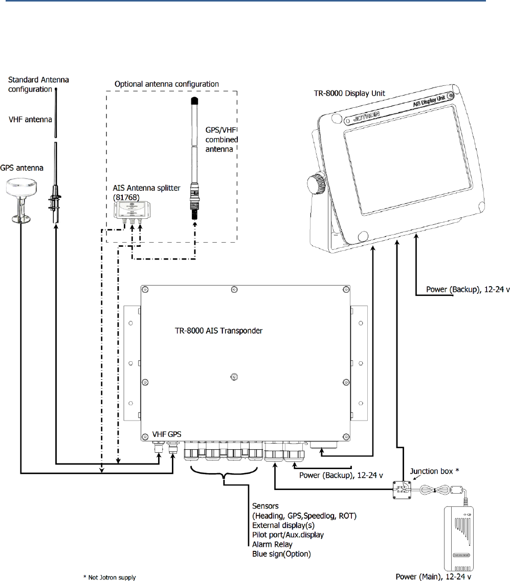
The Tron AIS TR-8000 consists of two separate units interconnected by Ethernet. The Transponder is the
main unit, handling the basic AIS functionality, including sensors and RF functions, while the Display unit
is used for setup and display of the AIS data.

TR-8000 Operator and Installation Manual 13
6.1 Functionality
The main features are:
Safety of navigation by
automatically exchanging
navigational data between ships
(Class A transponders), coast
stations, Class B transponders and
receiving positional data from
AIS-SARTs (Search and Rescue
beacons) and AtoNs (Aids to
Navigation).
Class A AIS transmitter
and receiver
(transponder)
Class B compatible
(receives all Class B
messages)
Short safety related messages and other short messages.
7” color LCD panel with LED backlight connects to transponder unit using Ethernet.
Interfaces for AIS compatible radar, ECDIS/ECS/Chart plotter and/or PC selectable through
RS422 (IEC 61162-2), RS232 or Ethernet (UDP).
GPS and VHF antenna separate or combined, for easy installation available.
Built-in GPS receiver for time synchronization and backup position.
SD-Card slot for future upgrades.
The information exchanged between ships using AIS transponders are:
Static data:
MMSI (Maritime Mobile Service Identity).
IMO number (where available).
Call sign and name.
Length and beam.
Type of ship.
Location of position-fixing antenna on the ship.
Dynamic data:
Ships position with accuracy indication and integrity status.
UTC.
Course over ground (COG).
Speed over ground (SOG).
Heading.
Navigation status (manual input).
Rate of turn (where available).
Voyage related data:
Ships draught.
Hazardous cargo (type).
Destination and ETA (at masters discretion).

TR-8000 Operator and Installation Manual 14
6.2 Transponder Unit
The Transponder Unit
contains all the core
functionality of the
AIS system and can
function as a
separate unit
connected to other
display solutions
confirming with the
AIS message format. It
consists of a splash
proof Alumina casing with the
following connection
possibilities:
VHF antenna and GPS
antenna
Display connector
(Ethernet)
External display
connections (“Ecdis
Port” and “Pilot/Aux
Port”).
Sensor connections
DGNSS/DGPS
Beacon receiver connection
Alarm relay
Complies with the environmental requirements specified in IEC 60945 Ed.4 Exposed, and is certified for
IP56 /IPX6. The operating temperature is from -25°C to +55°C and storage temperature from -30°C to
+70°C
The receiving section of the Transponder consists of three VHF receiver circuits, for continuous
reception on both AIS channels (configurable from 154MHz-164MHz) and the DSC channel (ch70).
The transmitter circuitry is connected to the same antenna terminal and is switched internally.
Functionality for direct reporting with satellites (Long-range AIS broadcast) is implemented and
operates when so configured by the competent authorities.
The internal power supply of the Transponder is galvanically isolated in order to protect the internal
circuitry and operates in a wide voltage input range from 10.8V – 31.2V. A backup power source can be
connected if available. Automatically switching to backup power source will take place if the main
source of power is lost.
Front View
Side View

TR-8000 Operator and Installation Manual 15
6.2.1 LED Indicators:
Transmission
Reception
Alarm
Status
6.2.2 Main functionality:
Transmit and receive AIS data packets over the VHF link
Receive DSC messages
Provide time and position data from internal GPS
Receive and handle data from external sensors.
Provide information about own and other ships positions to the display units, both the TR-8000
Display unit, and to high speed ports like “External Display” and “Pilot/Aux Display”.
6.2.3 VHF Antenna Connector
This is a BNC type antenna connector to be connected directly to an
external VHF antenna or antenna splitter to receive and transmit VHF
frequencies.
For more information see section 8.2.2
6.2.4 GPS Antenna Connector
This is a TNC type antenna connector to be connected directly to an
external GPS antenna or antenna splitter to receive GPS information.
For more information see section 8.2.1
TR-8000 Operator and Installation Manual 16
6.2.5 External Display (Ethernet) Connector
RJ45 type waterproof Ethernet connection
For more information see section 8.3.1.5
6.2.6 Multipurpose Cable Glands
The Transponder Unit
is fitted with up to 9
multipurpose cable
glands for waterproof,
shielded connection
with the unit. There
are 3 different sizes in
order for the best
possible fit for
different cable types.
All wiring should be
drawn in shielded cables connected to the chassis of the Transponder by the cable glands.
The multipurpose connection glands are provided as in .
Max Quantity
Min Cable Outer
Ø [mm]
Max Cable Outer
Ø
[mm]
Minimum Ø above
braiding [mm]
Recommended use
3
3.5
7
2
Sensors
4
4.5
9
4
Communication
2
7
12.5
5
Power
Table 1: Quantity and specification of multipurpose cable glands.

TR-8000 Operator and Installation Manual 17
6.3 Display Unit
Front View
The Display unit is the user interface for the
AIS system on the bridge. It is used to
configure the TR-8000 system and to present
AIS data about own and other ships, both
graphically and in list form. The Display Unit
consists of a splash proof housing with a 7 inch
LCD colour display with touch screen. Splash
proof connections for Main and Backup
power, Pilot plug and Transponder (Ethernet)
are present on the back side of the unit. The
internal power supply is switched in order to
obtain a high efficiency over the whole voltage
input range from 10.8V – 31.2V. A Backup
power source can be connected if available.
This will be automatically switched in if the
main source of power is lost.
The main features of the Tron AIS Display Unit are:
Give the user information about other ships with AIS in the vicinity.
Enable the user to obtain information about other ships and send and receive safety messages
to other ships with AIS Transponders.
CPA/TCPA
Enable the user to configure the AIS System.
Alert the user about alarms from the AIS system.
Pilot Port connection directly to the Display Unit.
Certified to IP54 and IEC 60945 Ed.4 “Protected”.
Operating temperature from -25°C to +55°C and storage temperature from -30°C to +70°C
Rear View

TR-8000 Operator and Installation Manual 18
7 Operational description
The operational description chapter assumes that the TR-8000 Ais Transponder is fully installed using
the instructions found in the Installation chapter.
7.1 On/Off button
ON/OFF button handles 3 different options
When ON/OFF is pushed, a popup menu is displayed with some display Options.
Additionally, if the brightness is low, it will automatically be increased. This feature can be used if the
user by some reason has too low visibility to adjust the brightness the regular way. If the Default
Brightness button is pressed, the brightness will be set to a 50% value. Otherwise the current brightness
level will be restored when the dialog is closed.
7.1.1 Clean Screen
Clean Screen is a function which turns off all touch sensitivity, enabeling the user to clean the screen
without pushing buttons unintentionally.

TR-8000 Operator and Installation Manual 19
7.1.2 Power off Display
If the Power off Display is selected, only the Display Unit is turned OFF and the AIS functionality of the
Transponder will still be active. Note that the ship list will need some time to recover when turning the
Display unit on again. This is dependent on when the messages from the different vessels are received.
The message logs for sent and received messages will also be lost.
Note that the Transponder unit will issue an alarm when the display is shut down, and there may be no
means to acknowledge this alarm if the display is turned off!

TR-8000 Operator and Installation Manual 20
7.2 Display Unit menu system.
The main window contains three main sections.
7.2.1 Status Bar
o
o
The Status bar is visible in all the sub menus.
Status Bar
Content Section
Button Bar
Dynamic navigational data
(Position, Speed, Heading etc.)
Clock
Other informative icons
(Tx,Rx, Nav status, Alarms etc. )

TR-8000 Operator and Installation Manual 21
7.2.2 Content Section
Displays the current selected window and the corresponding data
Example below shows Main View:
Main View is a combination of Graphical and List view:
All menus, menu buttons and settings are displayed in this section.
7.2.3 Button Bar
Contains all the functional buttons for above window:
Config Messages Display Voyage Down Up Enter List
The functionality of the buttons on the Button Bar is dependent on the content of the Content Section.
Graphical
List
Zoom Out
Zoom In
Rings
Base Station
Selected
Target
AIS-SART
AToN
Own Ship
Press column to Sort
SAR Aircraft
North
or
Head
Up
Vessels displayed
Number of vessels received

TR-8000 Operator and Installation Manual 22
7.2.4 Important Buttons shown in different Views:
Return to last menu without saving.
Confirm, save data and return to last menu.
If the Icon is not highlighted, indicates no data has changed
The Home button will take you to Main view without saving.
Enter – Show detailed information (“Page 1”) on selected item
Will be shown when vessel is selected with Enter button and
will show “Page 2” of information about vessel
When “Page 2” of Vessel information is shown, this button can be used to switch back to
“Page 1”
Arrow Down –Select next item on a list
Arrow Up –Select previous item on a list
Arrow Right – Select item to the right
Arrow Left – Select item to the left
Configuration – of Own ship, Display, Regions, Alarms, Indicators and Advanced
Messages – See Received and Sent messages, Reply to received and send New
Display setting – Adjust Brightness or select Day/Night mode
Voyage settings – Nav. Status, Destination, ETA, Draught, Cargo, Persons aboard
Some of the functions cannot be altered without entering a password. There are two levels of
passwords, a user password and an administrator password. The default passwords are “OP” and “SE”.

TR-8000 Operator and Installation Manual 23
7.2.5 Indicating ICONS
Receive data on either of the two AIS channels. If Inactive, shown as
Transmit on either channel A or B shown as TxA or TxB. Icon shown is Inactive.
Active is shown with Green color as the Rx icon above.
Alarm Status:
No alarms
Alarm caused by one or more incidents from Table 3
Navigation Status:
Under way using Engine
At Anchor
Not Under Command
Restricted Manoeuvrability
Constrained by her draught
Moored
Aground
Fishing
Sailing
Transmission Modes :
Silent Mode - Transmission is turned OFF
Normal transmission mode (12.5W)
Low Power (1 W) if
Vessel type = “Tanker” and
speed is below 3 knots and
Navigation Status = “Moored”
TR-8000 Operator and Installation Manual 24
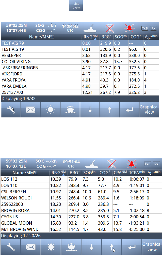
7.2.6 Ship List
The display unit receives data
about all the ships with an
active AIS transmitter in the
area and presents this data in a
list in the main window. The list
displays the name or MMSI,
range to own ship, bearing and
age of presented data. When
the graphical view is off, course
and speed are also displayed.
The list can be sorted on any of
these criteria, but an AIS SART
will always be presented at the
top of the list.
The columns “Name/MMSI”, “RNG”,”BRG” and “Age” are always present, but “SOG” and “COG” may be
replaced by “CPA” and “TCPA” or added in addition (See paragraph 10.2.3 )
Example of all listed:

TR-8000 Operator and Installation Manual 25
7.2.6.1 Column description
Name/MMSI :
Shows the MMSI (Maritime Mobile Service Identity) of the ship until its Name is
received. Name is transmitted more seldom than MMSI numbers
RNGNM:
Is the Range to the Vessel in Nautical Miles (NM)
BRG°:
Bearing to the Vessel in degrees from your position
SOGkn :
Speed Over Ground in Knots
COG°:
Course Over Ground in degrees
CPANM:
Closest Point of Approach : An estimated point in which the distance between you and
the other vessel are at its minimum value
TCPAmin:
Time To Closest Point of Approach : The time (in Minutes) until you reach the CPA
Agemin:
Shows how many minutes since last reception from this vessel
TR-8000 Operator and Installation Manual 26
7.2.7 Graphical View
The graphical
display of the
ship list plots
the positions
of other AIS
targets
relative to
your own
position in a
frame on the
left side.
A vessel with neither a reported heading nor COG will be oriented toward the top of display area.
The user is able to switch between North Up and Head Up, but if no heading or COG is available, or
if the ship is anchored/moored, the North Up configuration will automatically be chosen. If a valid
heading is received from external heading sensor (Gyro, Satellite compass or similar), own ship will be
oriented according to this. If heading is lost, Course Over Ground (COG) will be second choice for own
ships orientation on the display.
The setup is done in the Display Settings menu. In this menu, it is also possible to toggle between
Graphical and List view as default.
In the display menu, the user can choose not to return to the graphical view when exiting menus.

TR-8000 Operator and Installation Manual 27
Different types of targets are displayed with different icons.
Active Vessel
If the CPA/TCPA system is activated, ships on collision course are displayed with a red
color and double thickness of the lines.
Own ship is indicated in the same way as other ships, but is always in center.
Sleeping target
Smaller symbol than “Active Vessel” without a beam line
Sleeping targets are defined based on either:
Range more than X Nautical miles
Class B
Activation can be either of the definitions above and can be visible or not
AIS base station
AtoN
An Aids to navigation buoy indicating that it is off position is indicated with a red
color.
AIS SART. Will be displayed with a red color.
AIS TEST will be displayed with normal color.
SAR Aircraft
TR-8000 Operator and Installation Manual 28
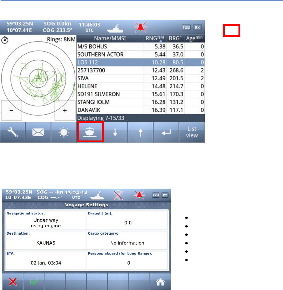
7.3 Voyage Settings
Red square shows
button selected to get to
this menu
The Voyage Settings contains all the ship data to be entered or changed before or on each voyage. In
order for the AIS system to function correctly, it is important to keep these parameters up to date.
You may use one of these buttons:
Navigational Status
Destination
ETA (Estimated Time of Arrival)
Draught
Cargo Category
Persons Aboard
to set correct information for the
Voyage

TR-8000 Operator and Installation Manual 29
7.3.1 Navigational Status
The options available for the
navigational status are as follows.
Under way using engine,
At anchor,
Not under command 1,
Restricted manoeuvrability 2,
Constrained by her draught 3,
Moored,
Aground,
Engaged in fishing 4
Under way sailing 5
Not Defined (Default) 6
1 Vessel not under command means a vessel which through some exceptional circumstance is unable to
maneuver as required by these Rules and is therefore unable to keep out of the way of another vessel.
2 Vessel restricted in her ability to manoeuver means a vessel which from the nature of her work is
restricted in her ability to manouvre as required by these Rules and is therefore unable to keep out of
the way of another vessel. The term “vessels restricted in their ability to manoeuvre” shall include but
not be limited to:
o A vessel engaged in laying, servicing or picking up a navigation mark, submarine cable or
pipeline;
o A vessel engaged in dredging, surveying or underwater operations;
o A vessel engaged in replenishment or transferring persons, provisions or cargo while
underway;
o A vessel engaged in the launching or recovery of aircraft;
o A vessel engaged in mine clearance operations;
o A vessel engaged in a towing operation such as severely restricts the towing vessel and her
tow in their ability to deviate from their course.
3 Vessel constrained by her draught means a power-driven vessel which, because of her draught in
relation to the available depth and width of navigable water, is severely restricted in her ability to
deviate from the course she is following.
4 Engaged in fishing means any vessel fishing with nets, lines, trawls or other fishing apparatus which
restrict manoeuvrability, but does not include a vessel fishing with trolling lines or other fishing
apparatus which do not restrict manoeuvrability.
5Under ways sailing means any vessel under sail provided that propelling machinery, if fitted, is not
being used.
6Not Defined (Default) is used when TR-8000 is delivered from factory. Then none of above selections
are made

TR-8000 Operator and Installation Manual 30
7.3.2 Destination
The destination of the voyage is to be entered here using a maximum of 20 characters.
NOTE!
Many countries require destination
input is according to GUIDANCE ON
THE USE OF THE UN/LOCODE IN THE
DESTINATION FIELD IN AIS
MESSAGES from
IMO SN/Circ.244
Text from the Guidance:
Recommended use of the UN/LOCODE
6. The recommended format is to indicate the port of departure at the first six positions of the data field followed by a
separator and then the code for the next port of call.
7. In order to identify that it is a LOCODE, to separate the locations and to indicate the ‘from’ and ‘to’ ports, a ‘>’. symbol
should be used as a separator. See example below.
A ship is leaving Dubai bound for Rotterdam. Use of the UN/LOCODE would represent this voyage as below:
“AE DXB>NL RTM”
8. If the next port of call is unknown, “?? ???” should be entered instead of the UN/LOCODE in the corresponding place in
the data field. See example below:
”AE DXB>?? ???”
9. If the port of departure does not have a designated UN/LOCODE then “XX XXX” should be entered instead of the
UN/LOCODE in the corresponding place in the data field. See example below:
“XX XXX>US PBI”
10. If the next port of call does not have a designated UN/LOCODE the commonly accepted English name of the
destination port should be entered, preceded by “===” (3 “equals signs”). If no such name is known, the locally used name
should be entered. In this case, there may not be enough space available to indicate the port of departure. See example below:
“===Orrviken”
11. If only the general area of destination is known the name or accepted abbreviation of the area preceded by “===”
(“three equals signs”) should be entered. See example below:
“NL RMT> === US WC”
Indicating a destination on the United States West Coast.
TR-8000 Operator and Installation Manual 31
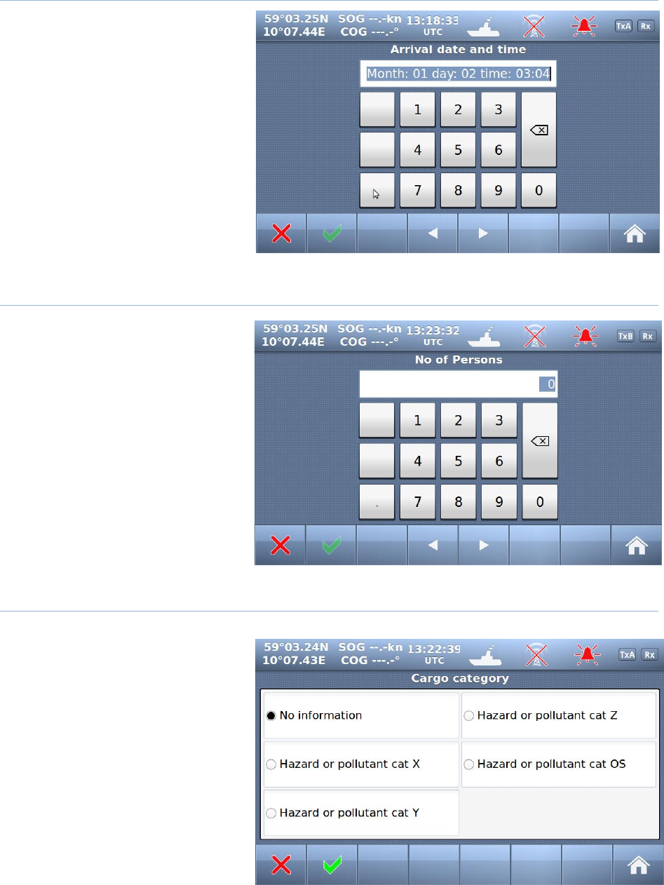
7.3.3 ETA
The Estimated Time of Arrival is
displayed to other AIS units and
should be updated if the expected
arrival time is changed.
7.3.4 Persons Aboard (optional)
This parameter indicates the
number of persons aboard the ship at
the given moment.
This parameter is not sent to other
ships or base stations, only through
the Long Range Port which is
normally not used (in 2011)
7.3.5 Cargo Category
Identifies Hazardous cargo,
depending on the ship class.
See chapter 10.1.1.1 <Type of Vessel>
for reference.

TR-8000 Operator and Installation Manual 32
7.3.6 Draught
The Draught parameter specifies the
maximum depth of the ship in meters and
decimeters.
TR-8000 Operator and Installation Manual 33
7.4 Messages
WARNING!
Use of AIS text messages between ships must not be used to avoid collisions when time is critical.
AIS
systems are not required to have an audible alarm to indicate the arrival of all text messages.
The use of AIS text messaging does not relieve the vessel of other requirements, such as the Vessel
Bridge-to-Bridge Radiotelephone regulations or of the requirements to sound whistle signals and
display lights or shapes in accordance with the International or Inland Navigation Rules.
Usage During Emergencies - With respect to using AIS safety related text messages in emergency
situations, users must be aware that they may not be received, recognized or acted upon as Global
Maritime Distress Safety Systems (GMDSS) messages would be by the Coast Guard, other competent
authorities or maritime first responders. Thus AIS must not be relied upon as the primary means for
broadcasting distress or urgent communications, nor used in lieu of GMDSS such as Digital Selective
Calling radios which are designed to process distress messaging. Nonetheless, AIS remains an effective
means to augment GMDSS and provides the added benefit of being ‘seen’ (on radar or chart displays),
in addition to being ‘heard’ (via text messaging) by other AIS users within VHF radio range (Ref: USCG
Safety Alert 05-10).
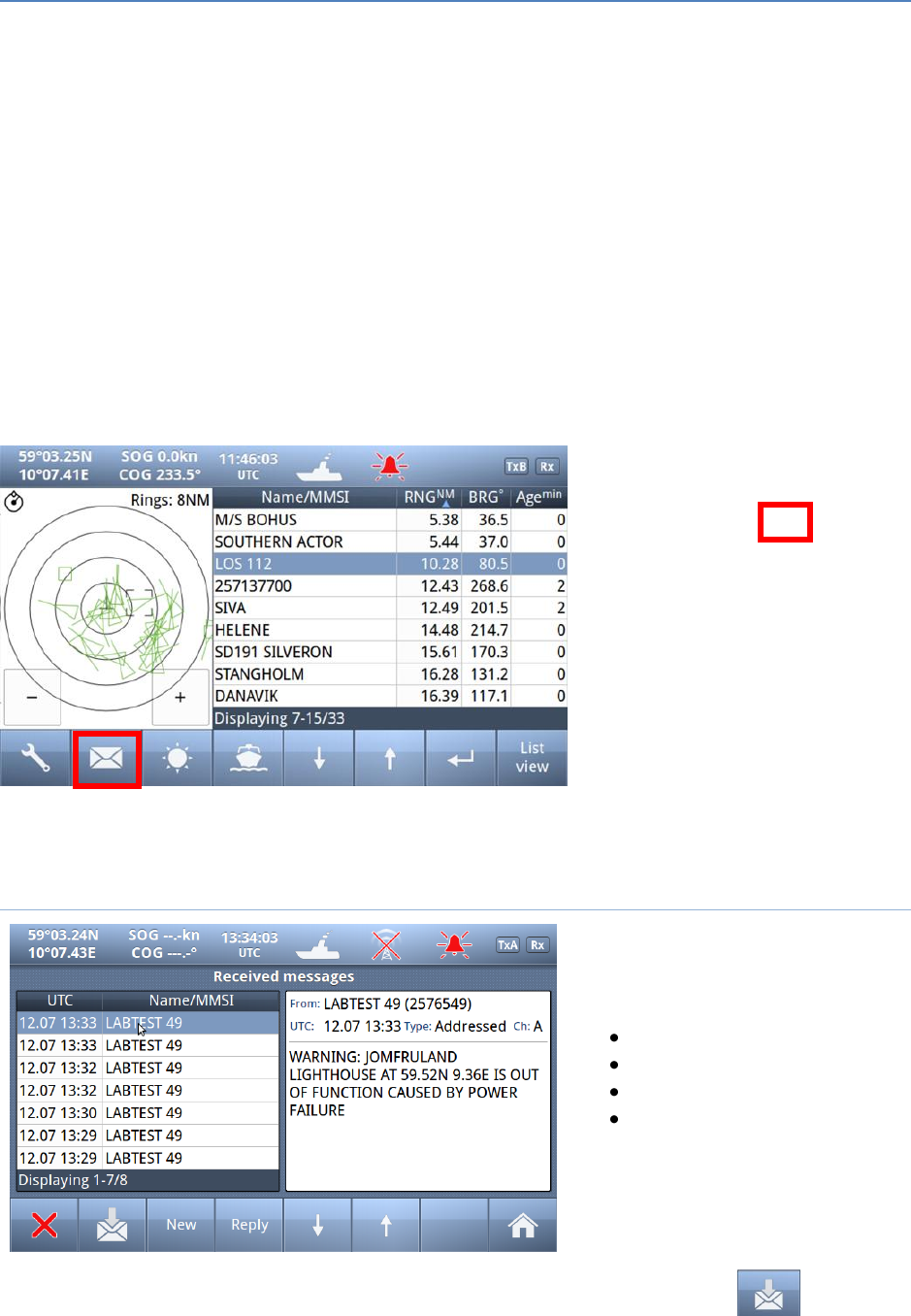
Red square shows
button selected to get to this menu
The messages Icon opens the
7.4.1 Received messages
By pushing the buttons on the bottom
bar, you can switch to:
Sent messages
Write New
Reply
Scroll up or down through
received messages
When you select one of the messages
in the list, you will see the content in
the right window
If you press the button, the display will swap to:

TR-8000 Operator and Installation Manual 34
7.4.2 Popup when received message
Example showing “Popup” of received
“Safety message” from AIS SART
The message must be acknowledged by
pressing “Close” button
7.4.3 Sent messages
By pushing the buttons on the bottom
bar, you can switch to:
Received messages
Write New
Resend
Scroll up or down through
sent messages
When you select one of the messages
in the list, you will see the content in
the right window
There is also a “Status” field on each line showing:
Message SENT OK
Message transmission in PROGRESS
Message transmission FAILED

TR-8000 Operator and Installation Manual 35
7.4.4 Write New message
Be advised, all messages in this context are
SAFETY RELATED and should not be used
for other purposes.
For this reason, this functionality is
protected by a user password.
Default Password = OP
Select here message recipients:
From list (Of received ships)
Enter MMSI (directly)
Broadcast (to all)

TR-8000 Operator and Installation Manual 36
7.4.4.1 Message recipients “From list”
Select
1. Which ship
2. Confirm with
Then a new window opens:
7.4.4.1.1 Write text
When a target is selected, the keyboard
window opens, and allows the user to write
a message. The total allowed length is 156
characters.
Confirm with
Which opens the
7.4.4.1.2 Choose channels and SEND
Select preference
Send :
TR-8000 Operator and Installation Manual 37
7.4.4.2 Message recipients “Enter MMSI”
1. Enter MMSI
2. Confirm with
3. Write Text (as described above)
4. Select Channel and Send (-“”-)
7.4.4.3 Message recipients “Broadcast”
1. Write Text (as described
above)
2. Select Channel and Send
TR-8000 Operator and Installation Manual 38
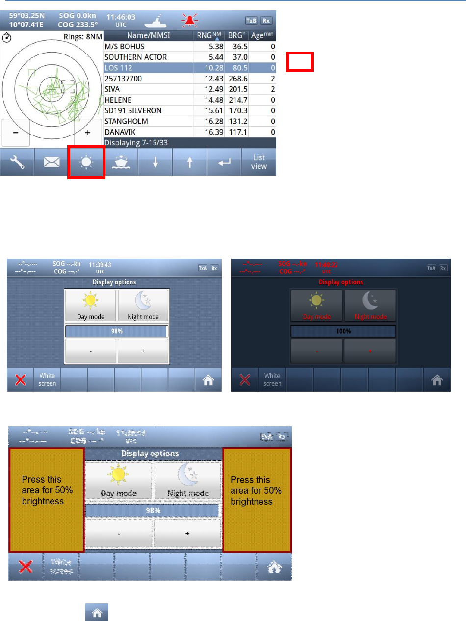
7.5 Display Settings
Red square shows
button selected to obtain to this menu
In the Display settings menu, you can adjust Brightness level and switch between night and day mode.
Each mode has its own brightnesslevel.
In the low brightness end of the scale, the steps are more accurate to adapt to very low intensity levels.
Touching the empty area at the left
or right side of the display restores a
50% brightness level if the display
gets too dark to see the actual
buttons for this purpose.
Restoring of 50% brightness level is
also accessable by pressing the
on/off button (see chapter 7.1)
Press “Home” to return to Main Window again
Operator and Installation Manual part1


TR-8000 Operator and Installation Manual 2
Table of Contents
1 Revision History ........................................................................................ 6
2 Software revisions..................................................................................... 7
3 Introduction .............................................................................................. 8
3.1 Safety Instructions ................................................................................................. 8
3.2 Compass Safe Distance ......................................................................................... 8
3.3 Copyright Notice.................................................................................................... 8
3.4 Disclaimer Notice .................................................................................................. 8
3.5 Disposal Instructions ............................................................................................. 9
3.6 Software and Hardware revisions ......................................................................... 9
3.7 Ingress protection ................................................................................................. 9
4 Operation general introduction ............................................................... 10
4.1 About AIS in general ............................................................................................ 10
5 Equipment List ........................................................................................ 11
5.1 Standard Supply .................................................................................................. 11
5.2 Optional Supply ................................................................................................... 11
6 TR-8000 Description ................................................................................ 12
6.1 Functionality ........................................................................................................ 13
6.2 Transponder Unit ................................................................................................ 14
6.2.1 LED Indicators: ............................................................................................................... 15
6.2.2 Main functionality: ......................................................................................................... 15
6.2.3 VHF Antenna Connector ................................................................................................ 15
6.2.4 GPS Antenna Connector ................................................................................................. 15
6.2.5 External Display (Ethernet) Connector .......................................................................... 16
6.2.6 Multipurpose Cable Glands ............................................................................................ 16
6.3 Display Unit ......................................................................................................... 17
7 Operational description .......................................................................... 18
7.1 On/Off button ..................................................................................................... 18
7.1.1 Clean Screen ................................................................................................................... 18
7.1.2 Power off Display ........................................................................................................... 19
7.2 Display Unit menu system. .................................................................................. 20
7.2.1 Status Bar ....................................................................................................................... 20
7.2.2 Content Section .............................................................................................................. 21
7.2.3 Button Bar ...................................................................................................................... 21
7.2.4 Important Buttons shown in different Views: ............................................................... 22
TR-8000 Operator and Installation Manual 3
7.2.5 Indicating ICONS............................................................................................................. 23
7.2.6 Ship List .......................................................................................................................... 24
7.2.6.1 Column description ....................................................................................................... 25
7.2.7 Graphical View ............................................................................................................... 26
7.3 Voyage Settings ................................................................................................... 28
7.3.1 Navigational Status ........................................................................................................ 29
7.3.2 Destination ..................................................................................................................... 30
7.3.3 ETA ................................................................................................................................. 31
7.3.4 Persons Aboard (optional) ............................................................................................. 31
7.3.5 Cargo Category ............................................................................................................... 31
7.3.6 Draught .......................................................................................................................... 32
7.4 Messages ............................................................................................................. 33
7.4.1 Received messages ........................................................................................................ 33
7.4.2 Popup when received message ..................................................................................... 34
7.4.3 Sent messages ................................................................................................................ 34
7.4.4 Write New message ....................................................................................................... 35
7.4.4.1 Message recipients “From list” ..................................................................................... 36
7.4.4.2 Message recipients “Enter MMSI” ................................................................................ 37
7.4.4.3 Message recipients “Broadcast” ................................................................................... 37
7.5 Display Settings ................................................................................................... 38
8 Installation .............................................................................................. 39
8.1 Mechanical Mounting ......................................................................................... 39
8.1.1 Transponder unit............................................................................................................ 39
8.1.2 Display Unit .................................................................................................................... 40
8.1.2.1 Desktop Mounting ........................................................................................................ 40
8.1.2.2 Roof Mounting .............................................................................................................. 41
8.1.2.3 Flush/ Panel Mounting ................................................................................................. 42
8.1.3 Antennas ........................................................................................................................ 43
8.1.3.1 GPS Antenna ................................................................................................................. 44
8.1.3.2 VHF Antenna ................................................................................................................. 46
8.2 Cabling ................................................................................................................. 47
8.2.1 GPS antenna ................................................................................................................... 47
8.2.2 VHF antenna ................................................................................................................... 48
8.2.3 Cable between Transponder and Display Unit .............................................................. 48
8.3 Wiring and Connections ...................................................................................... 49
8.3.1 Transponder ................................................................................................................... 50
8.3.1.1 Pictorial display of typical connections to the transponder ......................................... 51
TR-8000 Operator and Installation Manual 4
8.3.1.2 Label in transponder with connection tables ............................................................... 52
8.3.1.3 Power connection ......................................................................................................... 53
8.3.1.4 Sensor connections ....................................................................................................... 54
8.3.1.5 External display – ECDIS/Radar connections ................................................................ 55
8.3.1.6 Pilot / Aux. Display connection ..................................................................................... 56
8.3.1.7 Alarm Connection ......................................................................................................... 57
8.3.1.8 Detailed description of connections, fuses, factory reset etc. ..................................... 58
8.3.2 Display Unit: ................................................................................................................... 60
9 Initial configuration ................................................................................. 63
9.1 Short reference for initial configuration ............................................................. 63
9.2 Not all ships carry AIS .......................................................................................... 63
9.3 Use of AIS in collision avoidance ......................................................................... 63
9.4 Erroneous information ........................................................................................ 64
10 Operation Instructions ............................................................................ 65
10.1 Configuration Menu ............................................................................................ 65
10.1.1 Own Ship ........................................................................................................................ 65
10.1.1.1 Type of Vessel ............................................................................................................. 66
10.1.1.2 Ship Dimension and Antenna Position ....................................................................... 67
10.1.2 Display Settings .............................................................................................................. 68
10.1.2.1 Sleeping Targets.......................................................................................................... 68
10.1.2.2 Views .......................................................................................................................... 68
10.1.3 Regional Settings ............................................................................................................ 69
10.1.3.1 Current Region settings .............................................................................................. 69
10.1.3.2 View Regions .............................................................................................................. 70
10.1.3.3 Add Region .................................................................................................................. 71
10.1.3.4 Alarms ......................................................................................................................... 77
10.1.3.5 Alarm Relay Output .................................................................................................... 81
10.1.4 Indicators ....................................................................................................................... 82
10.2 Advanced Menu .................................................................................................. 83
10.2.1 Interface ......................................................................................................................... 83
10.2.1.1 Display/ Transponder IP ............................................................................................. 84
10.2.1.2 External display ........................................................................................................... 85
10.2.1.3 Aux. Display/Pilot Port ................................................................................................ 86
10.2.1.4 Baud rate .................................................................................................................... 87
10.2.1.5 Priorities...................................................................................................................... 88
10.2.1.6 Port Monitor ............................................................................................................... 89
TR-8000 Operator and Installation Manual 5
10.2.2 VHF link/Long Range ...................................................................................................... 90
10.2.2.1 Autonomous Long Range ............................................................................................ 90
10.2.2.2 Polled Long Range ...................................................................................................... 90
10.2.2.3 Silent mode ................................................................................................................. 91
10.2.2.4 Display SART in TEST mode ......................................................................................... 91
10.2.2.5 Test Communication ................................................................................................... 92
10.2.3 CPA/TCPA settings.......................................................................................................... 93
10.2.4 Internal GPS ................................................................................................................... 94
10.2.5 History Log ..................................................................................................................... 95
10.2.6 Self Test .......................................................................................................................... 96
10.2.7 System ............................................................................................................................ 97
10.2.7.1 Change password ........................................................................................................ 97
10.2.7.2 Update Firmware ........................................................................................................ 97
10.2.8 Current position ............................................................................................................. 98
11 Menu tree ............................................................................................... 99
12 List of VHF Channels .............................................................................. 100
13 Complied Standards .............................................................................. 101
14 Outline Drawings .................................................................................. 102
14.1 TR-8000 Transponder Unit ................................................................................ 102
14.2 TR-8000 Display Unit, Desktop or Overhead mount ......................................... 103
14.3 TR-8000 Display Unit, Flush/Panel mount ........................................................ 104
14.4 AIS Antenna Splitter .......................................................................................... 105
14.5 Procom CXL 2-1LW/h Maritime VHF Antenna .................................................. 106
14.6 Procom GPS 4 Antenna ..................................................................................... 107
14.7 SANAV – GPS Marine Antenna .......................................................................... 108
14.8 AC Marine VHF/GPS-B ....................................................................................... 109
15 Abbreviations and Definitions ............................................................... 110
16 Service Procedure ................................................................................. 114
16.1 Tron TR-8000 AIS Installation – registration form ............................................ 115
16.2 Trouble Description Form ................................................................................. 116
17 SERVICE AGENTS ................................................................................... 117
18 List of Figures ........................................................................................ 118

TR-8000 Operator and Installation Manual 6
1 Revision History
Revision
no.
By
Date
Page(s)
Versions
Reason for
change
Initial
FIT
30.1.2012
All
Transponder Unit:
HW: 1142-01
SW: 01.00.05 - 2141
Display Unit:
HW: 1125-00
SW: 01.00.05 - 2140
Manual: A
Initial release
1
FIT
7.2.2012
6, 8, 53,
86, 96
Manual: B
Typographic
errors, missing
references,
corrected
screenshots
2
FIT
2.3.2012
17,37
Manual: C
“Default
Brightness“
behaviour
change
3
FIT
17.4.2012
all
Manual: D
Changes related
to approval
process
4
FIT
4.6.2012
many
Manual: E
- New
screenshots
-Optional items
added
-Added cable
colour codes
- Changes
related to
simplified zoom
5
FIT
19.6.2012
6,7
Manual: F
-New Firmware
6
FIT
26.6.2012
6,7,53,54
Manual: G
-New Firmware
-Add cable sizes
TR-8000 Operator and Installation Manual 7
2 Software revisions
The TR-8000 is delivered with SW version according to table below which is filled in by either Jotron,
our Distributor, Dealer or Installation company. When SW update is done according to instructions in
Jotron TB 01-2012 (Technical Bulletin), an additional line of information will be filled in to reflect the
latest change. There will be no need for retraining after SW upgrade is performed.
The submeny that shows SW
versions can be found selecting:
(Configuration )
Advanced
System
Transponder
unit
Display
unit
By
Date
Change
01.00.05 - 2141
01.00.05 - 2140
Jotron
30.1.2012
Initial release
01.00.05 - 2240
01.00.05
SVN: 2208
Jotron
4.6.2012
Transponder:
- Improvements
Display:
- Simplified Zoom
01.00.05 - 2244
01.00.05
SVN: 2250
Jotron
19.6.2012
Transponder:
- Memory Init.
Display:
- Added zoom
- Fix:” Head up”
01.00.05 - 2255
Jotron
26.6.2012
Transponder:
- Fix: “Test Comm.”
- Fix: “TX malf.log”

TR-8000 Operator and Installation Manual 8
3 Introduction
3.1 Safety Instructions
This equipment should be installed according to the instructions found in the installation part of
this manual.
The equipment should not be mounted in a way that exposes it for excessive heat from the sun
or other sources.
The equipment should not be mounted in a flammable environment.
The equipment should not be mounted in a way that exposes it to direct rain or water.
CAUTION!
This equipment contains CMOS integrated circuits. Observe handling precautions to avoid static
discharges which may damage these devices.
Do not open equipment. Only qualified personell should service the equipment.
3.2 Compass Safe Distance
Transponder unit:
Standard Compass: 95cm
Steering compass: 65cm
Display unit:
Standard Compass: 30cm
Steering compass : 14cm
3.3 Copyright Notice
This manual, as well as the software described in it, is furnished under license and may be used or
copied only in accordance with the terms of such license. The content of this manual is furnished for
informational use only, is subject to change without notice, and should not be constructed as a
commitment by Jotron AS. Except as permitted by such license, no part of this publication may be
reproduced, stored in a retrieval system, or transmitted, in any form or by any means, electronic,
mechanical, recording, or otherwise, without the prior written permission by Jotron AS.
Please remember that existing artwork or images that you want to include in your project may be
protected under copyright law. The unauthorized incorporation of such material into your new work
could be a violation of the rights of the copyright owner. Please be sure to obtain any permission
required from the copyright owner.
3.4 Disclaimer Notice
The information in this book has been carefully checked and is believed to be accurate.
However, no responsibility is assumed for inaccuracies.
Jotron AS reserves the right to make changes without further notice to any products or modules
described herein to improve reliability, function or design.
Jotron AS does not assume any liability arising out of the application or use of the described product

TR-8000 Operator and Installation Manual 9
3.5 Disposal Instructions
The TR-8000 Transponder and Display shall be disposed according to local regulations regarding
Electronic Waste Recycling in the country the equipment is taken ashore.
At time of writing this manual (2012), there are some common regulations which allies:
Europe:
Directive 2002/96/EC (WEEE) Waste Electrical and Equipment Directive
Equipment is labeled with this symbol:
USA:
Most states have implemented some kind of recycling act, but there is not yet a federal law
about this issue.
Elsewhere:
Follow local regulations regarding disposal of electronic equipment
3.6 Software and Hardware revisions
See chapter 1 & 2
3.7 Ingress protection
Transponder unit:
IP56
IPx6
IEC 60945, Exposed
Display unit:
IP54
IEC 60945, Protected

TR-8000 Operator and Installation Manual 10
4 Operation general introduction
Thank you for purchasing this Jotron AIS Class A transceiver.
The Jotron TR-8000 has been developed to offer you the highest level of performance and durability
and we hope that it will provide many years of reliable service. This product has been designed to meet
the highest possible quality standards and should you encounter any problems with this product, please
contact your local dealer who will be pleased to offer any assistance.
4.1 About AIS in general
The system is based on the IMO regulation for AIS using Self Organized Time Division Multiple Access
(SOTDMA) technology based on a VHF Data Link (VDL).
The system operates in the following modes:
o Autonomous (continuous operation in all areas)
o Assigned (data transmission interval remotely controlled by authority in traffic monitoring
service)
o Polled (in response to interrogation from a ship or authority)
o Silent (listening only, use with caution)
The system is synchronized with GPS time (UTC) to avoid conflict among multiple users. If GPS data
is not available, the system is self synchronized using the VDL.
The VHF channels 2087 and 2088 are the main AIS channels in addition to local AIS frequencies.
AIS transponders onboard ships exchange various data as specified by IMO and ITU on either
frequency set up by :
o The frequency management telecommand (DSC)
o Special AIS messages sent from a AIS Base station.
o Manual input of special region
The normal transmit power is 12.5W, but under certain conditions, as during tanker loading
(according to ISGOTT regulation), or the use of regional settings, a low power option (1W) is
automatically selected.

TR-8000 Operator and Installation Manual 11
5 Equipment List
5.1 Standard Supply
85500 TR-8000 AIS Class A :
Stock No.
Name
Type
Qty.
85300
TR-8000 Transponder Unit
1
85400
TR-8000 Display Unit
1
85041
Mounting bracket, Display unit
1
85042
Locking ring, mounting bracket
2
85720
Curled knob, mounting bracket
2
86853
GPS Antenna, std
SANAV SA-200
1
86854
GPS Antenna stainless stand
1
86145
Cable, 5m Patch RJ45 waterproof
1
86848
Operator and Installation Manual
1
86581
Power cable, TR-8000 Display unit
1
Plug Kit consisting of:
TNC connector for RG214 cable
BNC Connector “ RG214 cable
Power connector
……
5.2 Optional Supply
Stock No.
Name
Type
82484
VHF Antenna
Procom CXL 2-1LW/h
84401
GPS/VHF combined antenna
AC Marine AIS/GPS-B
81768
Jotron Signal Splitter
86870
Pilot cable for TR-8000 display
Jotron
80665
AC/DC Power 100-240 VAC/ 24V DC
Jotron
92375
240V AC cable, Europe (for 80665)
Jotron
97521
AC Power cable, UK. (for 80665)
Jotron
81986
AC Power cable, USA (for 80665)
Jotron

TR-8000 Operator and Installation Manual 12
6 TR-8000 Description
The Tron AIS TR-8000 consists of two separate units interconnected by Ethernet. The Transponder is the
main unit, handling the basic AIS functionality, including sensors and RF functions, while the Display unit
is used for setup and display of the AIS data.
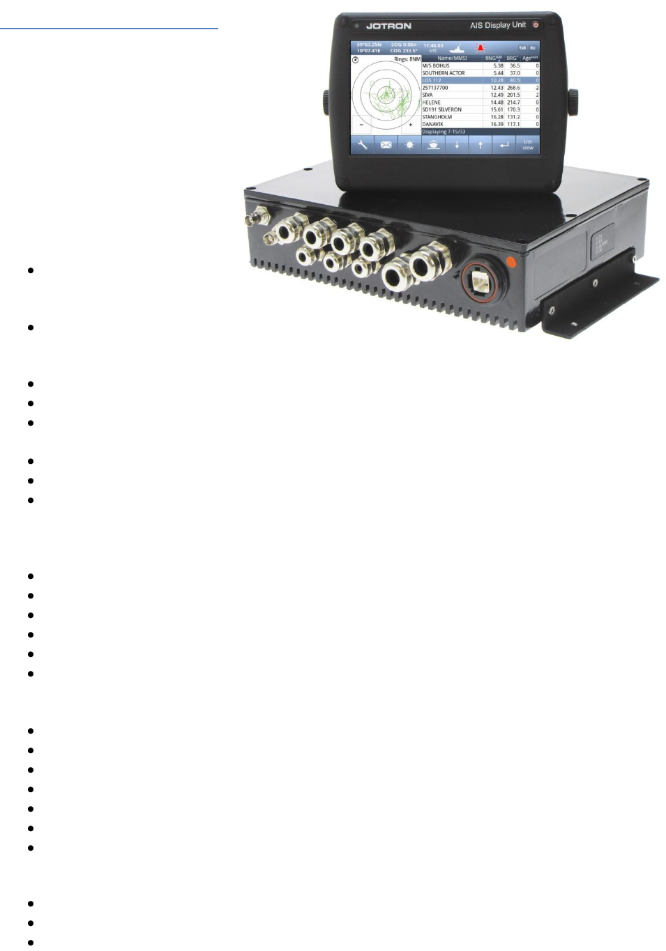
TR-8000 Operator and Installation Manual 13
6.1 Functionality
The main features are:
Safety of navigation by
automatically exchanging
navigational data between ships
(Class A transponders), coast
stations, Class B transponders and
receiving positional data from
AIS-SARTs (Search and Rescue
beacons) and AtoNs (Aids to
Navigation).
Class A AIS transmitter
and receiver
(transponder)
Class B compatible
(receives all Class B
messages)
Short safety related messages and other short messages.
7” color LCD panel with LED backlight connects to transponder unit using Ethernet.
Interfaces for AIS compatible radar, ECDIS/ECS/Chart plotter and/or PC selectable through
RS422 (IEC 61162-2), RS232 or Ethernet (UDP).
GPS and VHF antenna separate or combined, for easy installation available.
Built-in GPS receiver for time synchronization and backup position.
SD-Card slot for future upgrades.
The information exchanged between ships using AIS transponders are:
Static data:
MMSI (Maritime Mobile Service Identity).
IMO number (where available).
Call sign and name.
Length and beam.
Type of ship.
Location of position-fixing antenna on the ship.
Dynamic data:
Ships position with accuracy indication and integrity status.
UTC.
Course over ground (COG).
Speed over ground (SOG).
Heading.
Navigation status (manual input).
Rate of turn (where available).
Voyage related data:
Ships draught.
Hazardous cargo (type).
Destination and ETA (at masters discretion).
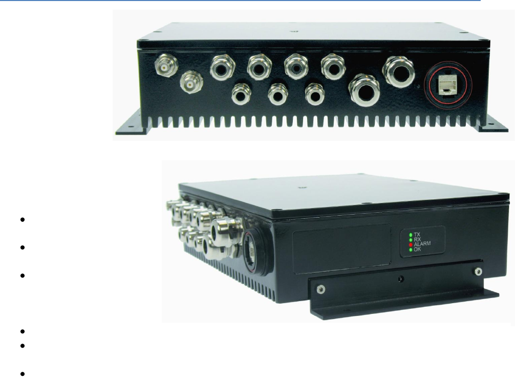
TR-8000 Operator and Installation Manual 14
6.2 Transponder Unit
The Transponder Unit
contains all the core
functionality of the
AIS system and can
function as a
separate unit
connected to other
display solutions
confirming with the
AIS message format. It
consists of a splash
proof Alumina casing with the
following connection
possibilities:
VHF antenna and GPS
antenna
Display connector
(Ethernet)
External display
connections (“Ecdis
Port” and “Pilot/Aux
Port”).
Sensor connections
DGNSS/DGPS
Beacon receiver connection
Alarm relay
Complies with the environmental requirements specified in IEC 60945 Ed.4 Exposed, and is certified for
IP56 /IPX6. The operating temperature is from -25°C to +55°C and storage temperature from -30°C to
+70°C
The receiving section of the Transponder consists of three VHF receiver circuits, for continuous
reception on both AIS channels (configurable from 154MHz-164MHz) and the DSC channel (ch70).
The transmitter circuitry is connected to the same antenna terminal and is switched internally.
Functionality for direct reporting with satellites (Long-range AIS broadcast) is implemented and
operates when so configured by the competent authorities.
The internal power supply of the Transponder is galvanically isolated in order to protect the internal
circuitry and operates in a wide voltage input range from 10.8V – 31.2V. A backup power source can be
connected if available. Automatically switching to backup power source will take place if the main
source of power is lost.
Front View
Side View
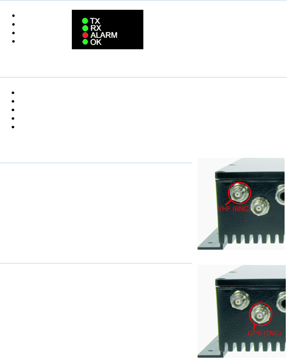
TR-8000 Operator and Installation Manual 15
6.2.1 LED Indicators:
Transmission
Reception
Alarm
Status
6.2.2 Main functionality:
Transmit and receive AIS data packets over the VHF link
Receive DSC messages
Provide time and position data from internal GPS
Receive and handle data from external sensors.
Provide information about own and other ships positions to the display units, both the TR-8000
Display unit, and to high speed ports like “External Display” and “Pilot/Aux Display”.
6.2.3 VHF Antenna Connector
This is a BNC type antenna connector to be connected directly to an
external VHF antenna or antenna splitter to receive and transmit VHF
frequencies.
For more information see section 8.2.2
6.2.4 GPS Antenna Connector
This is a TNC type antenna connector to be connected directly to an
external GPS antenna or antenna splitter to receive GPS information.
For more information see section 8.2.1

TR-8000 Operator and Installation Manual 16
6.2.5 External Display (Ethernet) Connector
RJ45 type waterproof Ethernet connection
For more information see section 8.3.1.5
6.2.6 Multipurpose Cable Glands
The Transponder Unit
is fitted with up to 9
multipurpose cable
glands for waterproof,
shielded connection
with the unit. There
are 3 different sizes in
order for the best
possible fit for
different cable types.
All wiring should be
drawn in shielded cables connected to the chassis of the Transponder by the cable glands.
The multipurpose connection glands are provided as in .
Max Quantity
Min Cable Outer
Ø [mm]
Max Cable Outer
Ø
[mm]
Minimum Ø above
braiding [mm]
Recommended use
3
3.5
7
2
Sensors
4
4.5
9
4
Communication
2
7
12.5
5
Power
Table 1: Quantity and specification of multipurpose cable glands.
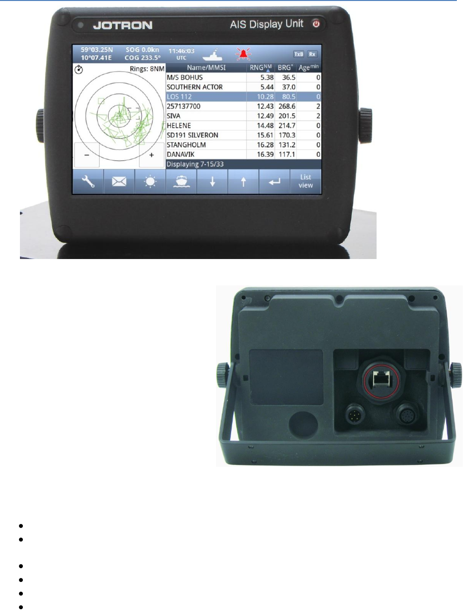
TR-8000 Operator and Installation Manual 17
6.3 Display Unit
Front View
The Display unit is the user interface for the
AIS system on the bridge. It is used to
configure the TR-8000 system and to present
AIS data about own and other ships, both
graphically and in list form. The Display Unit
consists of a splash proof housing with a 7 inch
LCD colour display with touch screen. Splash
proof connections for Main and Backup
power, Pilot plug and Transponder (Ethernet)
are present on the back side of the unit. The
internal power supply is switched in order to
obtain a high efficiency over the whole voltage
input range from 10.8V – 31.2V. A Backup
power source can be connected if available.
This will be automatically switched in if the
main source of power is lost.
The main features of the Tron AIS Display Unit are:
Give the user information about other ships with AIS in the vicinity.
Enable the user to obtain information about other ships and send and receive safety messages
to other ships with AIS Transponders.
CPA/TCPA
Enable the user to configure the AIS System.
Alert the user about alarms from the AIS system.
Pilot Port connection directly to the Display Unit.
Certified to IP54 and IEC 60945 Ed.4 “Protected”.
Operating temperature from -25°C to +55°C and storage temperature from -30°C to +70°C
Rear View
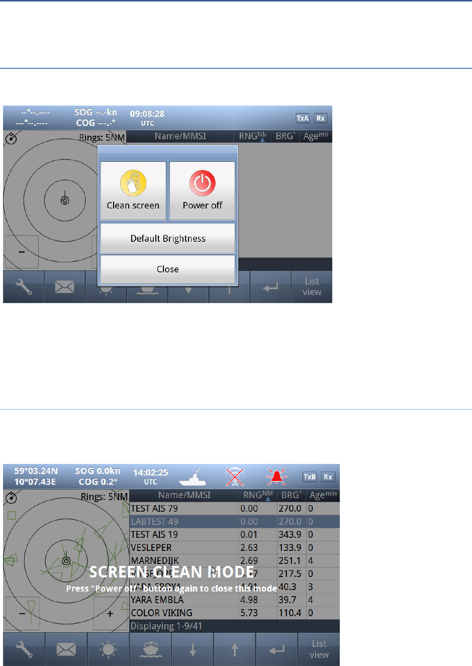
TR-8000 Operator and Installation Manual 18
7 Operational description
The operational description chapter assumes that the TR-8000 Ais Transponder is fully installed using
the instructions found in the Installation chapter.
7.1 On/Off button
ON/OFF button handles 3 different options
When ON/OFF is pushed, a popup menu is displayed with some display Options.
Additionally, if the brightness is low, it will automatically be increased. This feature can be used if the
user by some reason has too low visibility to adjust the brightness the regular way. If the Default
Brightness button is pressed, the brightness will be set to a 50% value. Otherwise the current brightness
level will be restored when the dialog is closed.
7.1.1 Clean Screen
Clean Screen is a function which turns off all touch sensitivity, enabeling the user to clean the screen
without pushing buttons unintentionally.

TR-8000 Operator and Installation Manual 19
7.1.2 Power off Display
If the Power off Display is selected, only the Display Unit is turned OFF and the AIS functionality of the
Transponder will still be active. Note that the ship list will need some time to recover when turning the
Display unit on again. This is dependent on when the messages from the different vessels are received.
The message logs for sent and received messages will also be lost.
Note that the Transponder unit will issue an alarm when the display is shut down, and there may be no
means to acknowledge this alarm if the display is turned off!
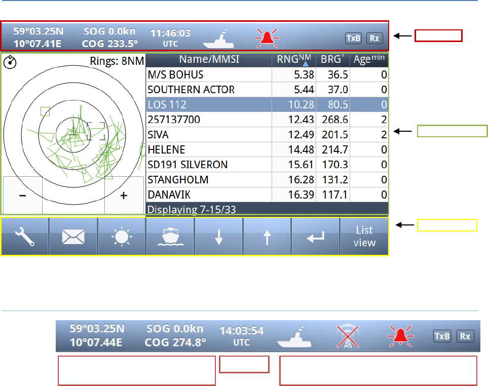
TR-8000 Operator and Installation Manual 20
7.2 Display Unit menu system.
The main window contains three main sections.
7.2.1 Status Bar
o
o
The Status bar is visible in all the sub menus.
Status Bar
Content Section
Button Bar
Dynamic navigational data
(Position, Speed, Heading etc.)
Clock
Other informative icons
(Tx,Rx, Nav status, Alarms etc. )
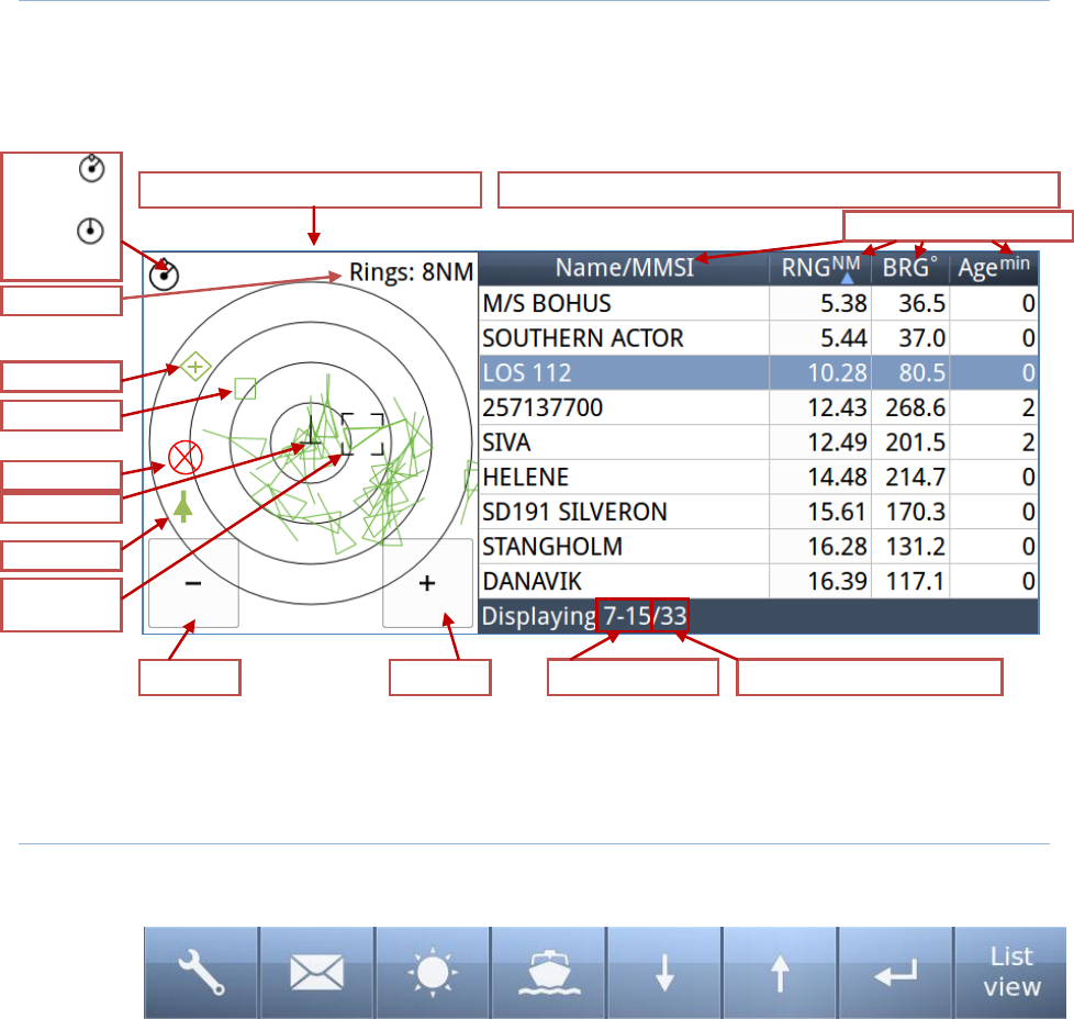
TR-8000 Operator and Installation Manual 21
7.2.2 Content Section
Displays the current selected window and the corresponding data
Example below shows Main View:
Main View is a combination of Graphical and List view:
All menus, menu buttons and settings are displayed in this section.
7.2.3 Button Bar
Contains all the functional buttons for above window:
Config Messages Display Voyage Down Up Enter List
The functionality of the buttons on the Button Bar is dependent on the content of the Content Section.
Graphical
List
Zoom Out
Zoom In
Rings
Base Station
Selected
Target
AIS-SART
AToN
Own Ship
Press column to Sort
SAR Aircraft
North
or
Head
Up
Vessels displayed
Number of vessels received
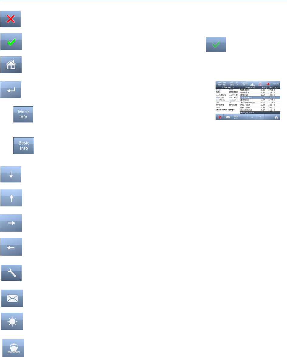
TR-8000 Operator and Installation Manual 22
7.2.4 Important Buttons shown in different Views:
Return to last menu without saving.
Confirm, save data and return to last menu.
If the Icon is not highlighted, indicates no data has changed
The Home button will take you to Main view without saving.
Enter – Show detailed information (“Page 1”) on selected item
Will be shown when vessel is selected with Enter button and
will show “Page 2” of information about vessel
When “Page 2” of Vessel information is shown, this button can be used to switch back to
“Page 1”
Arrow Down –Select next item on a list
Arrow Up –Select previous item on a list
Arrow Right – Select item to the right
Arrow Left – Select item to the left
Configuration – of Own ship, Display, Regions, Alarms, Indicators and Advanced
Messages – See Received and Sent messages, Reply to received and send New
Display setting – Adjust Brightness or select Day/Night mode
Voyage settings – Nav. Status, Destination, ETA, Draught, Cargo, Persons aboard
Some of the functions cannot be altered without entering a password. There are two levels of
passwords, a user password and an administrator password. The default passwords are “OP” and “SE”.

TR-8000 Operator and Installation Manual 23
7.2.5 Indicating ICONS
Receive data on either of the two AIS channels. If Inactive, shown as
Transmit on either channel A or B shown as TxA or TxB. Icon shown is Inactive.
Active is shown with Green color as the Rx icon above.
Alarm Status:
No alarms
Alarm caused by one or more incidents from Table 3
Navigation Status:
Under way using Engine
At Anchor
Not Under Command
Restricted Manoeuvrability
Constrained by her draught
Moored
Aground
Fishing
Sailing
Transmission Modes :
Silent Mode - Transmission is turned OFF
Normal transmission mode (12.5W)
Low Power (1 W) if
Vessel type = “Tanker” and
speed is below 3 knots and
Navigation Status = “Moored”

TR-8000 Operator and Installation Manual 24
7.2.6 Ship List
The display unit receives data
about all the ships with an
active AIS transmitter in the
area and presents this data in a
list in the main window. The list
displays the name or MMSI,
range to own ship, bearing and
age of presented data. When
the graphical view is off, course
and speed are also displayed.
The list can be sorted on any of
these criteria, but an AIS SART
will always be presented at the
top of the list.
The columns “Name/MMSI”, “RNG”,”BRG” and “Age” are always present, but “SOG” and “COG” may be
replaced by “CPA” and “TCPA” or added in addition (See paragraph 10.2.3 )
Example of all listed:

TR-8000 Operator and Installation Manual 25
7.2.6.1 Column description
Name/MMSI :
Shows the MMSI (Maritime Mobile Service Identity) of the ship until its Name is
received. Name is transmitted more seldom than MMSI numbers
RNGNM:
Is the Range to the Vessel in Nautical Miles (NM)
BRG°:
Bearing to the Vessel in degrees from your position
SOGkn :
Speed Over Ground in Knots
COG°:
Course Over Ground in degrees
CPANM:
Closest Point of Approach : An estimated point in which the distance between you and
the other vessel are at its minimum value
TCPAmin:
Time To Closest Point of Approach : The time (in Minutes) until you reach the CPA
Agemin:
Shows how many minutes since last reception from this vessel

TR-8000 Operator and Installation Manual 26
7.2.7 Graphical View
The graphical
display of the
ship list plots
the positions
of other AIS
targets
relative to
your own
position in a
frame on the
left side.
A vessel with neither a reported heading nor COG will be oriented toward the top of display area.
The user is able to switch between North Up and Head Up, but if no heading or COG is available, or
if the ship is anchored/moored, the North Up configuration will automatically be chosen. If a valid
heading is received from external heading sensor (Gyro, Satellite compass or similar), own ship will be
oriented according to this. If heading is lost, Course Over Ground (COG) will be second choice for own
ships orientation on the display.
The setup is done in the Display Settings menu. In this menu, it is also possible to toggle between
Graphical and List view as default.
In the display menu, the user can choose not to return to the graphical view when exiting menus.

TR-8000 Operator and Installation Manual 27
Different types of targets are displayed with different icons.
Active Vessel
If the CPA/TCPA system is activated, ships on collision course are displayed with a red
color and double thickness of the lines.
Own ship is indicated in the same way as other ships, but is always in center.
Sleeping target
Smaller symbol than “Active Vessel” without a beam line
Sleeping targets are defined based on either:
Range more than X Nautical miles
Class B
Activation can be either of the definitions above and can be visible or not
AIS base station
AtoN
An Aids to navigation buoy indicating that it is off position is indicated with a red
color.
AIS SART. Will be displayed with a red color.
AIS TEST will be displayed with normal color.
SAR Aircraft

TR-8000 Operator and Installation Manual 28
7.3 Voyage Settings
Red square shows
button selected to get to
this menu
The Voyage Settings contains all the ship data to be entered or changed before or on each voyage. In
order for the AIS system to function correctly, it is important to keep these parameters up to date.
You may use one of these buttons:
Navigational Status
Destination
ETA (Estimated Time of Arrival)
Draught
Cargo Category
Persons Aboard
to set correct information for the
Voyage
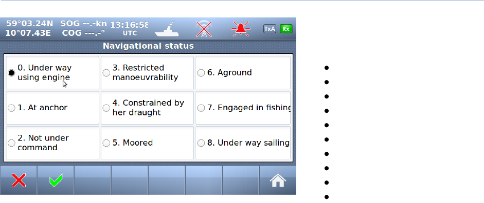
TR-8000 Operator and Installation Manual 29
7.3.1 Navigational Status
The options available for the
navigational status are as follows.
Under way using engine,
At anchor,
Not under command 1,
Restricted manoeuvrability 2,
Constrained by her draught 3,
Moored,
Aground,
Engaged in fishing 4
Under way sailing 5
Not Defined (Default) 6
1 Vessel not under command means a vessel which through some exceptional circumstance is unable to
maneuver as required by these Rules and is therefore unable to keep out of the way of another vessel.
2 Vessel restricted in her ability to manoeuver means a vessel which from the nature of her work is
restricted in her ability to manouvre as required by these Rules and is therefore unable to keep out of
the way of another vessel. The term “vessels restricted in their ability to manoeuvre” shall include but
not be limited to:
o A vessel engaged in laying, servicing or picking up a navigation mark, submarine cable or
pipeline;
o A vessel engaged in dredging, surveying or underwater operations;
o A vessel engaged in replenishment or transferring persons, provisions or cargo while
underway;
o A vessel engaged in the launching or recovery of aircraft;
o A vessel engaged in mine clearance operations;
o A vessel engaged in a towing operation such as severely restricts the towing vessel and her
tow in their ability to deviate from their course.
3 Vessel constrained by her draught means a power-driven vessel which, because of her draught in
relation to the available depth and width of navigable water, is severely restricted in her ability to
deviate from the course she is following.
4 Engaged in fishing means any vessel fishing with nets, lines, trawls or other fishing apparatus which
restrict manoeuvrability, but does not include a vessel fishing with trolling lines or other fishing
apparatus which do not restrict manoeuvrability.
5Under ways sailing means any vessel under sail provided that propelling machinery, if fitted, is not
being used.
6Not Defined (Default) is used when TR-8000 is delivered from factory. Then none of above selections
are made
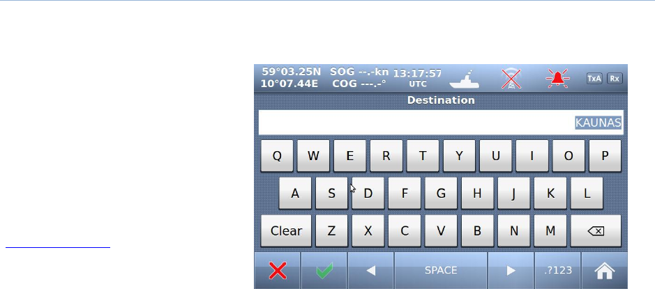
TR-8000 Operator and Installation Manual 30
7.3.2 Destination
The destination of the voyage is to be entered here using a maximum of 20 characters.
NOTE!
Many countries require destination
input is according to GUIDANCE ON
THE USE OF THE UN/LOCODE IN THE
DESTINATION FIELD IN AIS
MESSAGES from
IMO SN/Circ.244
Text from the Guidance:
Recommended use of the UN/LOCODE
6. The recommended format is to indicate the port of departure at the first six positions of the data field followed by a
separator and then the code for the next port of call.
7. In order to identify that it is a LOCODE, to separate the locations and to indicate the ‘from’ and ‘to’ ports, a ‘>’. symbol
should be used as a separator. See example below.
A ship is leaving Dubai bound for Rotterdam. Use of the UN/LOCODE would represent this voyage as below:
“AE DXB>NL RTM”
8. If the next port of call is unknown, “?? ???” should be entered instead of the UN/LOCODE in the corresponding place in
the data field. See example below:
”AE DXB>?? ???”
9. If the port of departure does not have a designated UN/LOCODE then “XX XXX” should be entered instead of the
UN/LOCODE in the corresponding place in the data field. See example below:
“XX XXX>US PBI”
10. If the next port of call does not have a designated UN/LOCODE the commonly accepted English name of the
destination port should be entered, preceded by “===” (3 “equals signs”). If no such name is known, the locally used name
should be entered. In this case, there may not be enough space available to indicate the port of departure. See example below:
“===Orrviken”
11. If only the general area of destination is known the name or accepted abbreviation of the area preceded by “===”
(“three equals signs”) should be entered. See example below:
“NL RMT> === US WC”
Indicating a destination on the United States West Coast.

TR-8000 Operator and Installation Manual 31
7.3.3 ETA
The Estimated Time of Arrival is
displayed to other AIS units and
should be updated if the expected
arrival time is changed.
7.3.4 Persons Aboard (optional)
This parameter indicates the
number of persons aboard the ship at
the given moment.
This parameter is not sent to other
ships or base stations, only through
the Long Range Port which is
normally not used (in 2011)
7.3.5 Cargo Category
Identifies Hazardous cargo,
depending on the ship class.
See chapter 10.1.1.1 <Type of Vessel>
for reference.

TR-8000 Operator and Installation Manual 32
7.3.6 Draught
The Draught parameter specifies the
maximum depth of the ship in meters and
decimeters.

TR-8000 Operator and Installation Manual 33
7.4 Messages
WARNING!
Use of AIS text messages between ships must not be used to avoid collisions when time is critical.
AIS
systems are not required to have an audible alarm to indicate the arrival of all text messages.
The use of AIS text messaging does not relieve the vessel of other requirements, such as the Vessel
Bridge-to-Bridge Radiotelephone regulations or of the requirements to sound whistle signals and
display lights or shapes in accordance with the International or Inland Navigation Rules.
Usage During Emergencies - With respect to using AIS safety related text messages in emergency
situations, users must be aware that they may not be received, recognized or acted upon as Global
Maritime Distress Safety Systems (GMDSS) messages would be by the Coast Guard, other competent
authorities or maritime first responders. Thus AIS must not be relied upon as the primary means for
broadcasting distress or urgent communications, nor used in lieu of GMDSS such as Digital Selective
Calling radios which are designed to process distress messaging. Nonetheless, AIS remains an effective
means to augment GMDSS and provides the added benefit of being ‘seen’ (on radar or chart displays),
in addition to being ‘heard’ (via text messaging) by other AIS users within VHF radio range (Ref: USCG
Safety Alert 05-10).
Red square shows
button selected to get to this menu
The messages Icon opens the
7.4.1 Received messages
By pushing the buttons on the bottom
bar, you can switch to:
Sent messages
Write New
Reply
Scroll up or down through
received messages
When you select one of the messages
in the list, you will see the content in
the right window
If you press the button, the display will swap to:
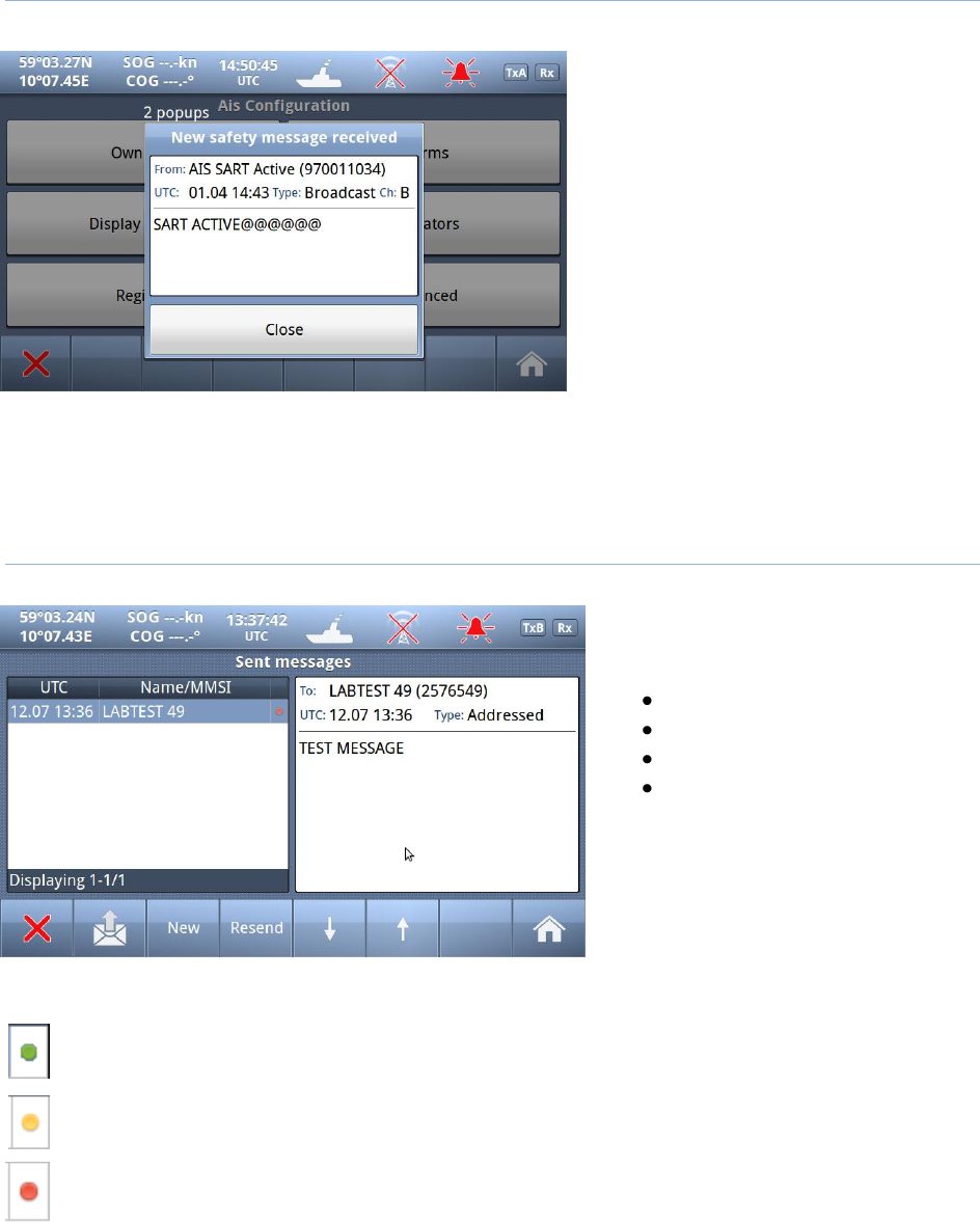
TR-8000 Operator and Installation Manual 34
7.4.2 Popup when received message
Example showing “Popup” of received
“Safety message” from AIS SART
The message must be acknowledged by
pressing “Close” button
7.4.3 Sent messages
By pushing the buttons on the bottom
bar, you can switch to:
Received messages
Write New
Resend
Scroll up or down through
sent messages
When you select one of the messages
in the list, you will see the content in
the right window
There is also a “Status” field on each line showing:
Message SENT OK
Message transmission in PROGRESS
Message transmission FAILED
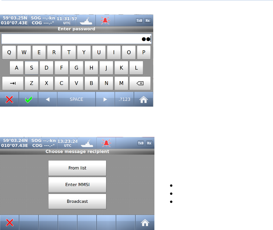
TR-8000 Operator and Installation Manual 35
7.4.4 Write New message
Be advised, all messages in this context are
SAFETY RELATED and should not be used
for other purposes.
For this reason, this functionality is
protected by a user password.
Default Password = OP
Select here message recipients:
From list (Of received ships)
Enter MMSI (directly)
Broadcast (to all)
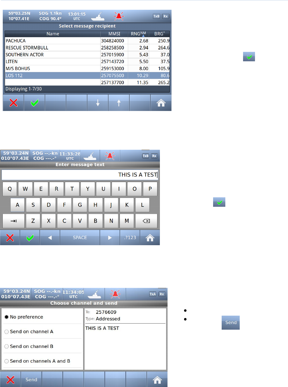
TR-8000 Operator and Installation Manual 36
7.4.4.1 Message recipients “From list”
Select
1. Which ship
2. Confirm with
Then a new window opens:
7.4.4.1.1 Write text
When a target is selected, the keyboard
window opens, and allows the user to write
a message. The total allowed length is 156
characters.
Confirm with
Which opens the
7.4.4.1.2 Choose channels and SEND
Select preference
Send :

TR-8000 Operator and Installation Manual 37
7.4.4.2 Message recipients “Enter MMSI”
1. Enter MMSI
2. Confirm with
3. Write Text (as described above)
4. Select Channel and Send (-“”-)
7.4.4.3 Message recipients “Broadcast”
1. Write Text (as described
above)
2. Select Channel and Send

TR-8000 Operator and Installation Manual 38
7.5 Display Settings
Red square shows
button selected to obtain to this menu
In the Display settings menu, you can adjust Brightness level and switch between night and day mode.
Each mode has its own brightnesslevel.
In the low brightness end of the scale, the steps are more accurate to adapt to very low intensity levels.
Touching the empty area at the left
or right side of the display restores a
50% brightness level if the display
gets too dark to see the actual
buttons for this purpose.
Restoring of 50% brightness level is
also accessable by pressing the
on/off button (see chapter 7.1)
Press “Home” to return to Main Window again