KATHREIN Sachsen ARU4ELCU6 UHF RFID Reader User Manual Installation Manual part 1
KATHREIN Sachsen GmbH UHF RFID Reader Installation Manual part 1
Contents
- 1. Antenna Installation Manual
- 2. Installation Manual part 1
- 3. Installation Manual part 2
- 4. User Manual
- 5. User Manual Antennas
Installation Manual part 1

Installation manual for
Kathrein RFID UHF-Reader
Installation manual Reader English
This document is valid for all Kathrein RFID readers and describes the construction and commissioning
of the readers.
Version 1.03
date of creation: 01.06.2012
document no.: 936B057
RRU4
ARU4
M-ARU
ERU
RDR
Installation manual Reader 2
Modications, misprints and errors excepted.
EnglishInstallation manual Reader
This manual applies to the followings ARU4 types:
Type: Order number:
ARU4-RS4-E6 52010099
ARU4-ETG-E6 52010100
ARU4-ETL-E6 52010101
ARU4-RS4-U6 52010102
ARU4-ETG-U6 52010103
ARU4-ETL-U6 52010104
ARU4-ELK-E6 52010225
ARU4-ELK-U6 52010226
ARU4-ELC-U6 52010171
This manual applies to the followings M-ARU types:
Type: Order number:
M-ARU-RS232 ETSI 52010135
M-ARU-RS232 FCC 52010136
M-ARU-ETH-E6 52010198
M-ARU-ETH-U6 52010199
RFID-UHF-Reader
This manual applies to the followings RRU4 types:
Type: Order number:
RRU4-RS4-E6 52010093
RRU4-ETG-E6 52010094
RRU4-ETL-E6 52010095
RRU4-RS4-U6 52010096
RRU4-ETG-U6 52010097
RRU4-ELC-E6 © KRAI 52010180
RRU4-ELC-U6 © KRAI 52010181
This manual applies to the followings ERU types:
Type: Order number:
ERU-ETG-E4 52010190
ERU4-ETG-U4 52010191
This manual applies to the followings RDR types:
Type: Order number:
RDR-ETH-E4 52010200
RDR-ETH-U4 52010201

Installation manual Reader 3
Modications, misprints and errors excepted
English
Foreword and general information
The reproduction or distribution of this document or extracts from it in whatever form and by whatever means (electronic or mechanical)
for whatever purpose is permitted only with the prior written permission of Kathrein.
Kathrein accepts no liability for omissions or inaccuracies in this document or in relation to the provision or use of the information
contained in this document. Kathrein reserves the right to change the products described in this document and does not accept any
liability in relation to the application or usage of the products described in this manual.
This document and the information contained in it are proprietary information of Kathrein and should be treated as condential.
Kathrein provides this document to its customers in connection with contacts of sale for the products described therein. If the person
in possession of this document, being a legal or natural person, is not a contractual sales partner of Kathrein, or Kathrein has not
intended him by other means as the recipient of the document and the information contained therein, the person in possession is hereby
informed that the use of this document is unlawful and a violation of the rights of Kathrein.
Copyright notice
The information in this manual was correct at the time of editorial deadline.
We reserve the right however to make changes at any time and without prior notice.
This document was prepared for specialist personal who install, congure and place in operation the reader.
Scope
The information contained in this manual is intended for the support of the development process and as development guidance
for the customer. In addition this manual offers supporting information about the standards to be applied at the place of installation
and the relevant safety standards for installation and conguration of the Kathrein reader.
General information
This manual contains information on the installation, conguration, operation and maintenance of the reader. In addition it gives
detailed technical data in order better to familiarise the user with the features of the reader.
In order to ensure a long working life and fault-free operation, this manual should therefore be read carefully and all the instructions
and information contained in it should be complied with.
Warranty
Switching on the AC or DC power supply prior to connecting the LAN cable is considered incorrect installation. Any functional defect
arising as a result is excluded from the warranty/guarantee. Before installing or servicing the reader, the person concerned must
have read the manual and understood its contents. Kathrein accepts no liability if the customer fails to implement the precautions
listed here. In such cases, any claims under the warranty/guarantee are void.
Disposal instruction
Electronic equipment is not classed as household waste and must be disposed of properly in accordance with
Directive 2002/96/EC OF THE EUROPEAN PARLIAMENT AND OF THE COUNCIL of 27 January 2003 on used
electrical and electronic equipment.
At the end of its service life, take this device for disposal at a designated public collection point.
Used batteries are special waste!
Do not put used batteries into your domestic waste; instead take them to a collection point for used batteries!
Further reading on this manual is as ((A)) in section 2.2. further reading or 7th list of references listed.

Installation manual Reader 4
Modications, misprints and errors excepted.
English
List of Contents
Foreword and general information 3
List of Contents 4
1. Safety instructions/information 6
2. Introduction 9
2.1. The reader 9
2.2. RFID system 9
2.3. Kathrein RFID Antenna Interface (© KRAI) 11
2.4. Wide Range © KRAI antenna 12
2.5. SMSH © KRAI planar antenna module 12
2.6. Further reference material 13
2.7. Scope of supply 13
2.8. Accessories 14
3. Installation 15
3.1. Selecting the installation site 15
3.2. Installing the reader RRU / ARU 15
3.3. Installing the reader ERU 16
3.4. Installing the reader RDR 17
3.5. Installing the reader M-ARU 18
4. Connections and displays 19
4.1. Power supply 19
4.2. Ethernet connection 20
4.3. RS422-/485 connection 20
4.4. RS232 connection 20
4.5. ERU connection 21
4.6. RDR connection 21
4.7. M-ARU connection 22
4.8. UART transmission (RS232, RS422, RS485 or similar) 23
4.9. Ethernet transmission 25
4.10. Anschlüsse M-ARU, RS232, 25
4.11. Antenna Connection 29

Installation manual Reader 5
Modications, misprints and errors excepted
English
List of Contents
4.12. LED 29
4.13. Buzzer 29
5. Software 30
5.1. System requirements 30
5.2. Installation 30
5.3. Operation 34
6. Operating the reader 39
6.1. Communication 39
6.2. Application 46
6.3. Basic read functions 48
6.4. Basic writing functions 51
6.5. GPIO functions 53
6.6. Expert settings 58
6.7. Test Gen2 functions 63
6.8. © KRAI Setting 67
6.9. App Manager 70
6.10. Access Manager 70
6.11. Ethernet password 77
6.12. configuration password 79
7. Programming the Reader 80
7.1. Preparation 80
7.2. Using the examples with Windows 80
7.3. Using the examples with Linux 80
7.4. Using the examples with Linux on a PC 80
7.5. Using on an embedded system 80
7.6. Installation Embedded Linux Development Kit (ELDK) 81
7.7. Installation Linux application 82
8. List of references 85
9. Contact address 86
Installation manual Reader 6
Modications, misprints and errors excepted.
English
1. Safety instructions/information
Key
Caution!
Note
Before starting installation work or replacing the unit, the accompanying manual must be read carefully and its
contents understood.
The detailed information in the data sheets and in this manual must be complied with carefully during installation and
operation of the reader!
The installation team must be properly qualied and familiar with the safety regulations applicable in the country
concerned.
Connection, installation and maintenance work, as well as all other work on the unit, may only be carried out by
properly qualied and trained employees.
The unit may only be used for the purpose intended by the manufacturer.
Unauthorized changes to the unit and the use of spare parts and peripheral devices which are not sold or
recommended by the manufacturer can result in res, electric shocks and injuries. Such actions therefore result in
exclusion of liability and make the manufacturer’s warranty/guarantee null and void.
The applicable version of the manufacturer’s warranty is that which was valid at the time of purchase. We accept
no liability for unsuitable manual or automatic adjustments made to the unit's parameters and inappropriate use of
the unit.
Repairs may only be undertaken by personnel authorised to perform them. Opening or attempting to repair the
unit makes all guarantee/warranty claims null and void! Improper work on the unit may jeopardise electrical safety.
The manufacturer is not liable for accidents caused by the user opening the unit!
When carrying out work on the unit, the valid safety regulations must be complied with.
Supply voltage
Make sure that the mains cable (power supply cable) is not damaged. If the mains cable is damaged, the device
must not be used. Instead it must be disconnected from the mains and repaired by a qualied technician. Use only
the power supply unit supplied!
Risk of fatal injury due to electric shock!
The device may be operated only at the stated supply voltage (see the rear of the device or external power supply unit)!
If the supply voltage is too high, there is a risk of re!
General safety notes
Important!
Indicates a potentially dangerous situation which, if disregarded, can lead to injuries ranging
from minor to severe and/or damage to the unit.
Information intended to make a specic topic easier to understand and/or enable optimal use
of the unit functions.
Important!
Installation manual Reader 7
Modications, misprints and errors excepted
English
1. Safety instructions/information
CE marking for the Kathrein RFID reader with type designation "E6"
Appropriate means are provided to dissipate the heat generated within this equipment. The device must however not be
installed in a cabinet or on shelves with insufcient ventilation. The ventilation slots on the device must not be covered.
There is a risk of re!
Ventilation
Protect the device from moisture, dripping water and spraying water. The device must not be placed close to sources of
heat, exposed to direct sunlight or operated in a damp environment. The device may not be operated only is moderate
climatic zones. It is unsuitable for use under tropical conditions! Do not place anything which has a naked ame on the
device! 1)
There is a risk of re!
Moisture, direct sunlight, heat, naked ames
This reader is designed “E6” for operation as per EN 302208. When the unit is operated with antennas connected,
the human exposure regulations in accordance with EN 50364 must be complied with. Ensure a minimum clearance
of 20 cm between the antenna and the human body, and comply with the operating instructions for RFID antennas. In
some circumstances, heart pacemakers may suffer interference if wearers are close to the antenna when the unit is
in operation (reader and antenna). In case of doubt, the people affected are requested to contact the manufacturer of
their pacemaker or their doctor.
The reader output power must be reduced as a function of the antenna cable length and the antenna gain.
Radiated electromagnetic elds
Marking for the Kathrein RFID reader with type designation "U6"
The reader with the identier „U6“ are designed to operate under FCC Part 15 and can be found at the FCC homepage
under grantee code „WJ9“.
This device complies with part 15 of the FCC Rules. Operation is subject to the following two conditions: (1) This device
may not cause harmful interference, and, (2) This device must accept any interference received including interference
that may cause undesired operation.
Industry Canada
Le présent appareil est conforme aux CNR d‘Industrie Canada applicables aux appareils radio exempts de licence.
L‘exploitation est autorisée aux deux conditions suivantes : (1) l‘appareil ne doit pas produire de brouillage, et (2)
l‘utilisateur de l‘appareil doit accepter tout brouillage radioélectrique subi, même si le brouillage est susceptible d‘en
compromettre le fonctionnement.
Under Industry Canada regulations, this radio transmitter may only operate using an antenna of a type and maximum
(or lesser) gain approved for the transmitter by Industry Canada. To reduce potential radio interference to other users,
the antenna type and its gain should be so chosen that the equivalent isotropically radiated power (e.i.r.p.) is not more
than that necessary for successful communication.
This radio transmitter has been approved by Industry Canada to operate with the antenna types listed at page 8 with
the maximum permissible gain and required antenna impedance for each antenna type indicated. Antenna types not
included in this list, having a gain greater than the maximum gain indicated for that type, are strictly prohibited for use
with this device.
Modications or conversions which are carried out on this unit without the express permission of Kathrein may
invalidate the FCC permit for the operation of this unit.
Important!
Important!
Important!
Installation manual Reader 8
Modications, misprints and errors excepted.
English
1. Safety instructions/information
Note
Following corresponding tests, it has been ascertained that this unit adheres to the limit values for class B digital
units in accordance with part 15 of the FCC regulations. These limit values are intended to provide private user's
systems with appropriate protection against harmful radio interference. This unit generates and uses energy
in the radio frequency range and is also able to radiate this; if it is not installed and used in accordance with the
regulations, the unit may cause harmful radio communication interference. However, there is no guarantee that
interference will not occur in a specic system. If this unit causes harmful radio or television reception interference,
which can be ascertained by switching the unit on and off, we recommend that the user attempts to rectify this
interference via one or more of the following measures:
- Realign the receive antenna or change its position.
- Increase the distance between the unit and the receiver.
- Plug the unit into a socket in a current circuit other than that to which the receiver is connected.
- Seek advice from the retailer or an experienced radio/television technician.
Warning regarding exposure to RF radiation
Note
To meet part 15 of the FCC regulations in the United States, the system must be properly installed to guarantee
adherence to the certication regulations according to part 15. The operator and the specialist company which carries
out installation are responsible for ensuring that only certied systems are used in the United States. Use of this
system in any other combination (e.g. several antennas which transmit the same information in the same location)
is expressly prohibited.
Note regarding proper installation:
Important!
FCC RF Radiation Exposure Statement
This transmitter must not be co-location or operating in conjunction with any other antenna or transmitter.
This equipment complies with FCC RF radiation exposure limits set forth for an uncontrolled environment.
This equipment should be installed and operated with a minimum distance of 20 centimeters between the radiator and
your body.
This equipment complies with IC RSS-102 radiation exposure limits set forth for an uncontrolled environment.
This equipment should be installed and operated with minimum distance 20cm between the radiator & your body.
Type Order-No. Shortened designation Gain
WiRa 30° FCC 52010087 Wide Range-Antenna FCC, 902-928 MHz, 30° circular 11dBiC/ 8DBi
WiRa 70° FCC 52010079 Wide Range-Antenna FCC, 902-928 MHz, 70° circular typ. 11dBi
MiRa FCC 52010083 Mid Range-Antenna FCC, 902-928 MHz, 1000° circular 2.5dBi
S-MiRa ETSI/FCC 52010172 Short-Range-Antenna FCC, 865-928 MHz, 100° circular typ -10dBi
U-LoRa ETSI/FCC 52010092 Ultra Low Range-Antenna FCC, 865-928 MHz -30dBi
LoRa FCC 52010085 Low Range-Antenna FCC, 902-928 MHz -15dBi
WiRa-30-linear-FCC 52010249 Wide Range-Antenna 30° linear FCC, 902-828 MHz, 30° linear typ. 11dBi
WiRa-40-linear-FCC 52010252 Wide Range-Antenna 40° linear FCC, 902-828 MHz, 40° linear typ. 13dBi
SMSH-30-30ETSI-
FCC-Antennenmodul 52010219 Smart Shelft-Antenna, 865-928 MHz, non cascadable -7dBi
Installation manual Reader 9
Modications, misprints and errors excepted
English
2. Introduction
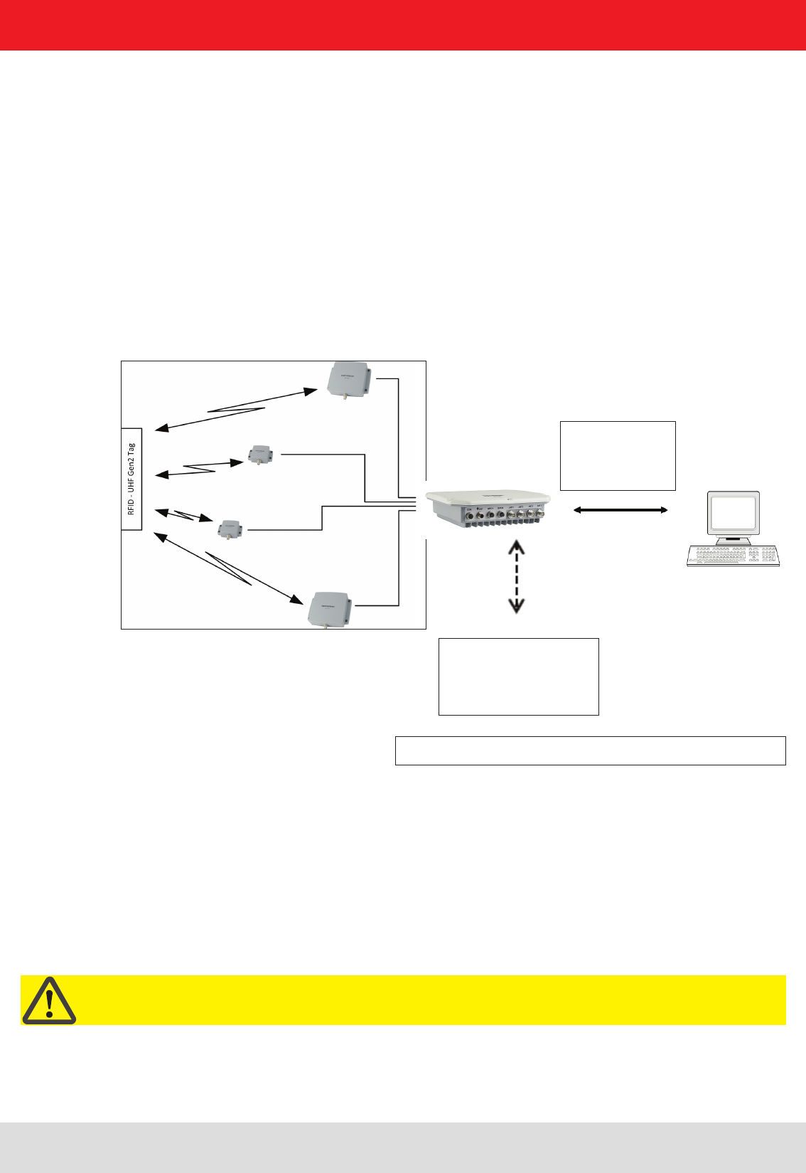
2.2. RFID system
An RFID system consists of the control computer of the actual reader, antennas, antenna connection cables and the
tags. The gure below shows the schematic structure of the system:
The tags consist of an antenna and a small chip. The chip is the true carriers of the information,
the EPC number. This number can be identied products or product groups. Alternatively, the EPC can be overwritten
with new information.
To read the tag information, the reader sends an RF carrier by an active antenna and thus supplies the tags in the RF
eld with energy.
If the information in one tag should be read, this tag should be rst selected (inventoried) from the population of tags.
Upon successful completion of the inventory, the EPC number of each tag can be read and sent to the PC. Additional
information can be attached to the EPC, for example the antenna which read it the time point at which it was read.
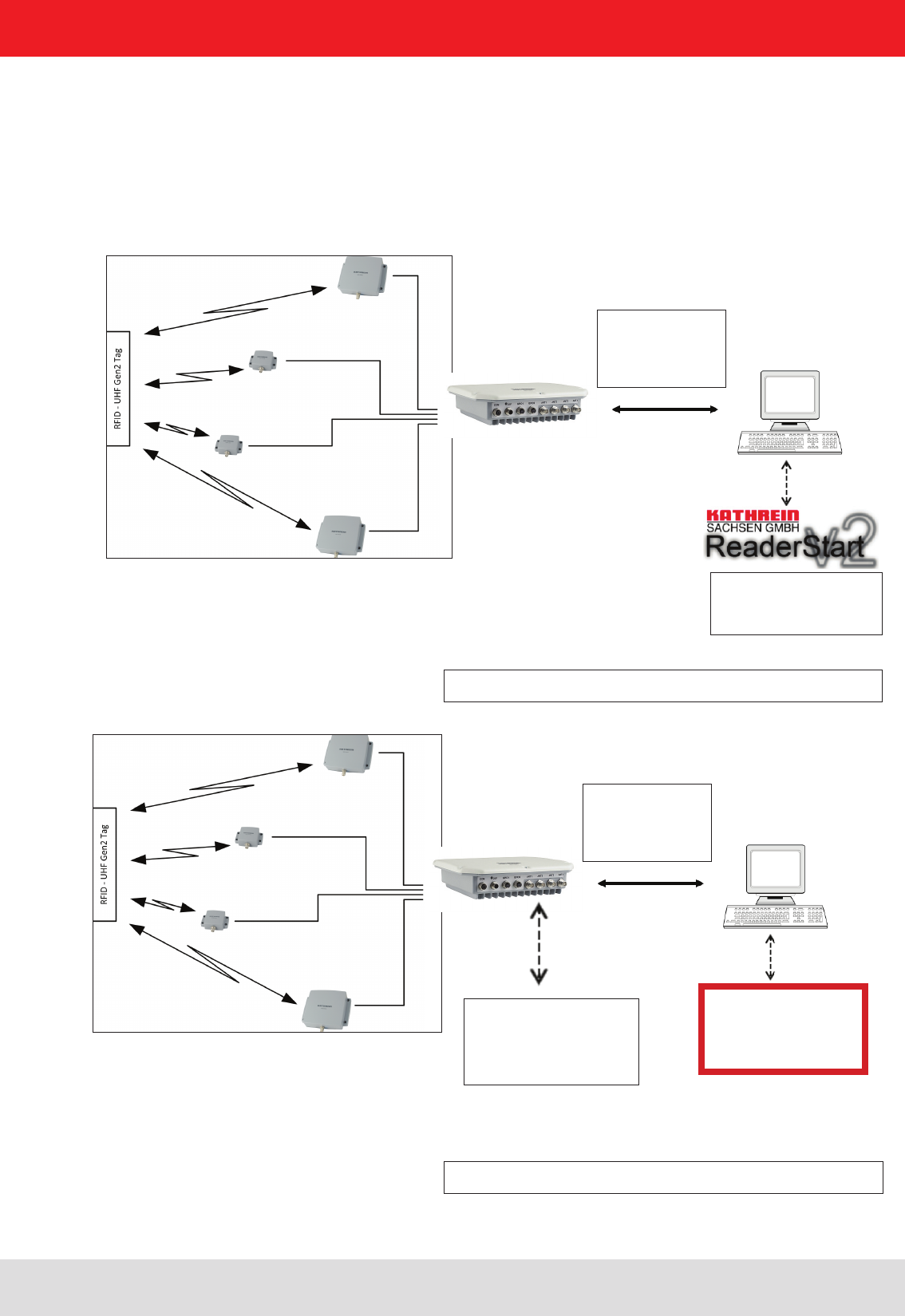
Figure: continuous operation ETL and ELC RFID system
By the ETL and ELC
Reader is an industrial
PC with Linux operating
system is integrated.
RS232
RS422/485
Ethernet
2.1. The reader
The Kathrein RFID (Radio Frequency Identication) reader RRU4 is a multi-protocol-capable device for reading active
and passive RFID tags in the frequency range from 865 to 868 MHz for Europe type “E6” and 902 to 928 MHz for the
American market type “U6”. As supplied the unit can read and write tags in accordance with the EPC-Gen2 standard.
Additional protocols can be loaded using software updates.
The device has a maximum of four external antenna ports for connection of the transmission/reception antennas for
communication with RFID tags.
For integration into a variety of infrastructures, the device has different communication interfaces depending on the
variant. The power supply is provided by a 4-pin M12 panel connector in A coding.
Important!
The reader operates using the frequency hopping process, so as to avoid faults and interference between readers.
Within the FCC area this procedure is mandatory. The readers changes its transmission frequency randomly,
with equal distribution across the 52 available channels. Each channel is used for max. 400ms in an interval of 20s.
Installation manual Reader 10
Modications, misprints and errors excepted.
English
For testing and parameterizing the reader the Demo Software“Reader Start v2”can be used.
The communication between the“Reader Start v2” and the reader is based on the DLL, which includes the commu-
nication protocol ((A)). For specic applications the user can build its own control software based on the reader DLL.
The DLL includes all the relevant commands and functions, which are needed to control the reader
Figure: Testing and conguration of the RFID system
RS232
RS422/485
Ethernet
By the ETL and ELC
Reader an industrial PC
with Linux Operating
System is integrated.
RS232
RS422/485
Ethernet
Figure: Continuous operation of the ETL and ELC RFID system
The control software
must be created by
the user.
The user-specic control software can run on ETL reader directly. Thus, a stand-alone operation without permanent
network connection is possible.
The demo software
Reader Start is included.
2. Introduction
Installation manual Reader 11
Modications, misprints and errors excepted
English2. Introduction
2.3. Kathrein RFID Antenna Interface © KRAI
By using Kathrein © KRAI antennas, reading rates can be increased by 33% compared to simple circular
antennas.
The Kathrein-RFID Antenna Interface © KRAI consists of a digital control bus, which enables connection
between the RFID reader and the RFID antennas in order to allow control and regulation tasks in remote
antennas.
The phase control elements integrated in the © KRAI antennas enable static or dynamic adjustment of
antenna characteristics.
Due to this, four different polarizations can be selected for the new 70° Wide Range antenna (type 52010193
WIRA-70-KRAI-ETSI): RHCP / LHCP/ horizontal linear / vertical linear
One can choose between static polarization and automatic switch-over. As the Kathrein-RFID Antenna In-
terface © KRAI is transmitted over the standard antenna cable, no additional lead or connection is required
to control the new antenna types.
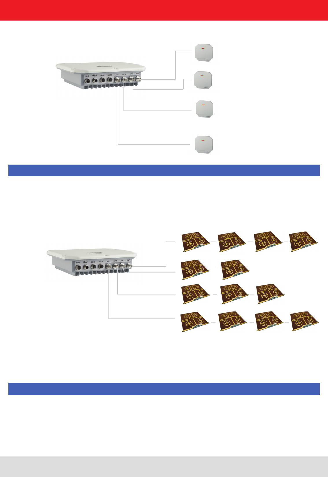
The Kathrein RFID © KRAI system permits the cascading of up to 8 SMSH antennas at a single antenna
port. This allows selective access to up to 32 individual antennas. This allows the reading result to be linked
to the antenna recognition (e.g. antenna 3 (5)) and be output.
With the new © KRAI product series Kathrein has introduced a revolutionary system.
Installation manual Reader 12
Modications, misprints and errors excepted.
English
2.4. Wide Range © KRAI antenna
Please ensure that the rmware of your KRAI-capable reader and the reader start conguration software
are release 2.40 or higher.
Note
Note
WiRa-70-KRAI antennas cannot be cascaded.
A maximum of 8 SMSH antennas can be cascaded per rea-
der port.
2.5. SMSH © KRAI planar antenna module:
Installation manual Reader 13
Modications, misprints and errors excepted
English
2.6. Further reference material
In order to congure the reader correctly and adapt it to the respective application, detailed knowledge of the
EPCGlobal standards of GS1 is necessary ((E)). This standard describes the principle of operation of the interface
between the tag and reader.
The parameters available for the conguration of the reader is available as described in the “conguration manual
Reader” ((B))
The reader is controlled via the Kathrein-Reader protocoll (KBRP). The document “communication protocol” ((A)) in the
current version contains a detailed description of the protocol
Note
The versions of the documents must match the software version of the reader. The CD supplied contains the current
documents for the reader rmware supplied.
2.7. Scope of supply
The package includes a CD next to each reader with a parameter, and test software (Reader Start), programming
examples, DLL and operating
((E)) EPCTM Radio-Frequency Identity Protocols Class-1 Generation-2 UHF RFID in version V1.2.0 :
www.epcglobalinc.org
„communication protocol“ ((A)) for software developers
„congurational manual reader“ ((B)) for commissioning
„installation manual reader“ ((C)) Setup and installation
"installation manual antenna“ ((D)) Setup and installation
„EPCGlobal standard“ ((E)) for software developers
„Putty is SSH and Telnet-Client“ ((F)) for software developers
Installation manual Reader 14
Modications, misprints and errors excepted.
English
2. Introduction
- Cable sets (without antenna cable)
Order number Type for Series Product type
52010125 CK-RRU RS4 RRU4/ARU4 Power supply cable, RS 422/485, GPIO, length 1.5 m
52010126 CK-RRU ETG RRU4/ARU4 Power supply cable, Ethernet interface cable, GPIO-cable,
length 1.5 m
52010189 CK-M-ARU RS M-ARU Combination cable for power supply GPIOs, RS232 interface
length 1.5 m
52010209 CK-M-ARU PoE M-ARU Combination cable for power supply and PoE interface,
length 1.5 m
52010238 R-CC 10 ETH RRU4/ARU4/
M-ARU
Ethernet Connecting Cable, length 10 m
52010239 R-CC 10 GPIO RRU4/ARU4 GPIO Connecting Cable, length 10 m
52010240 R-CC 10 DC RRU4/ARU4 DC power supply Connecting Cable, length 10 m
52010241 R-CC 10 RS M-ARU Connecting Cable M-ARU, length 10 m
2.8. Accessories
The following accessories are available for the reader (if you have questions about the accessories, please contact
our Sales Ofce):
- Antennas: For use with UHF-RFID antennas; we recommend the Kathrein antenna types ULoRa, LoRa,
MiRa, WiRa. These antenna types are available for all frequency ranges.The mentioned types of antennas are
available for all frequency ranges and in screwed condition tight IP 65.
Order number Type Connector 1 Connector 2 Lenght (cm)
52010174 R-AC 3 TNC-TNCR
TNC TNC Reverse
LL240 ex, 300
52010175 R-AC 6 TNC-TNCR LL240 ex, 600
52010176 R-AC 10 TNC-TNCR LL240 ex,1000
52010177 R-AC 15 TNC-TNCR LL240 ex,1500
52010250 R-AA N-TNC N-Socket TNC (socket) LL440 ex,1500
52010090 R-AC 3 SMA-TNCR SMA (socket) TNC (socket) RG 58, 300
52010208 R-AC 05 SMA-SMA SMA (socket) SMA (socket) RG 58, 50
- Antenna cable
Order number Type Product type
52010178 R-AA TNC-N(f-m) Adapter TNC-N (f-m)
52010243 R-AA TNC-SMA (f-m) Adapter SMA (f-m)
- Antenna adapter
Installation manual Reader 15
Modications, misprints and errors excepted
English
- Mounting Accessories
- Protective Covers
Order number Type Product type
52010179 R-RPA 115-230V/24V RRU / ARU 230V power supply with safty plug (Lörar);
24V DC power supply with M12 socket 4-pin, A-coded
52010192 R-ERPA 115-230V/24V ERU 230V power supply
24V DC cable plug connector 2.5 mm
Order number Type Product type
52010127 Protective covers set for the
RRU and ARU reader series
Accessories for RRU4/ARU4 reader with screw caps for
3x antenna input (R-TNC) and 2x digital (M12)
- Readers power supply
- Montageset und Wand-/Masthalterung
Bestellnummer Typ Bestehend aus
52010005 MK-AMB-100-Outdoor Poll Mount Kit for 30° WiRa antennas
52010128 MK-WPM-100-100-Outdoor Wall/Pole Mount Kit for WiRa 70 ° an-
ennes and RRU4/ARU4-Readern
52010261 MK-WM-100-100-Indoor Wall Mount Kit for WiRa 70°antennas and
RRU-, ARU- Reader; Indoor
52010262 MK-WPM-100-100-Outdoor Wall/Pole Mount Kit for WiRa 40°antennas; Outdoor
2. Introduction
Installation manual Reader 16
Modications, misprints and errors excepted.
English
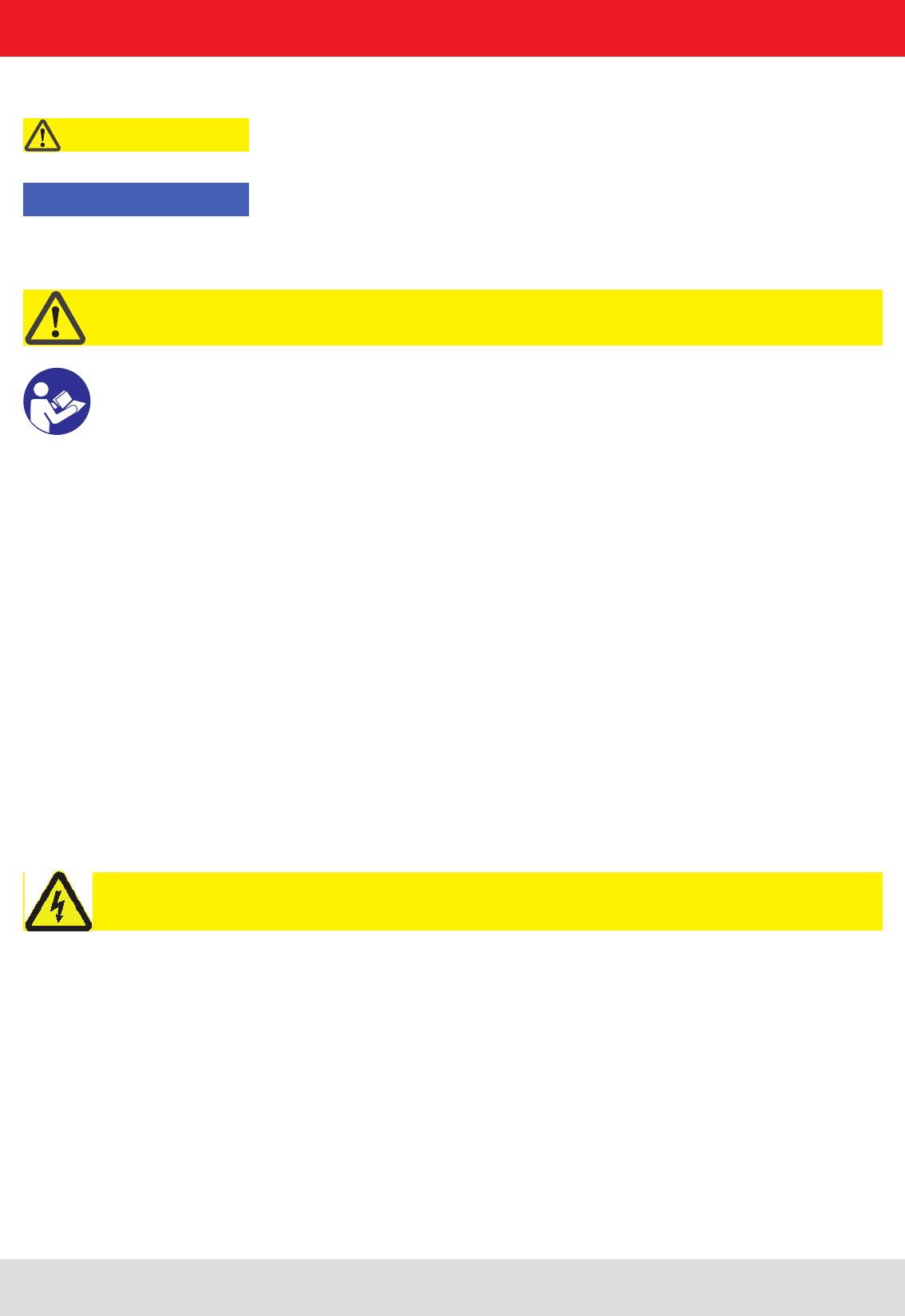
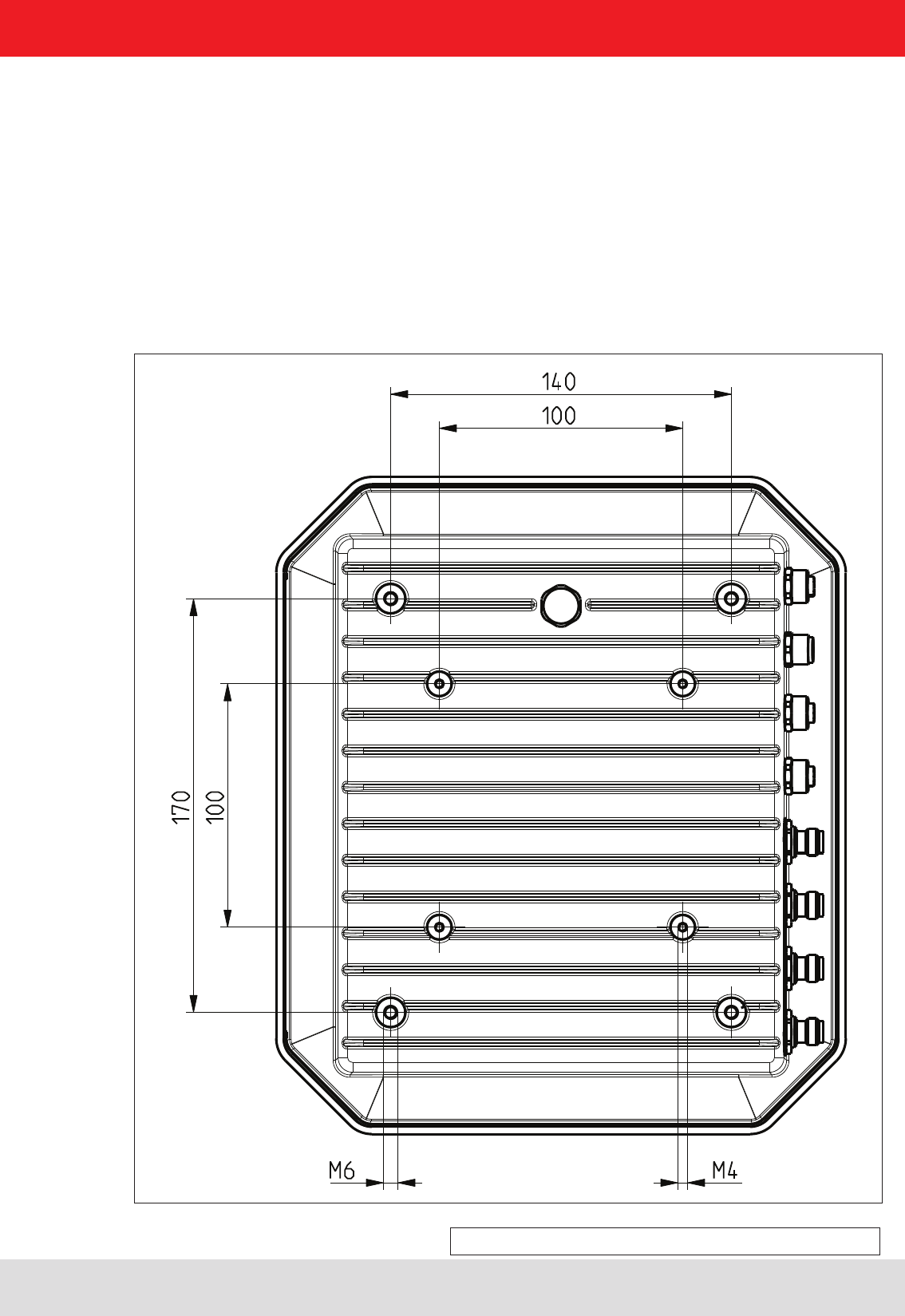
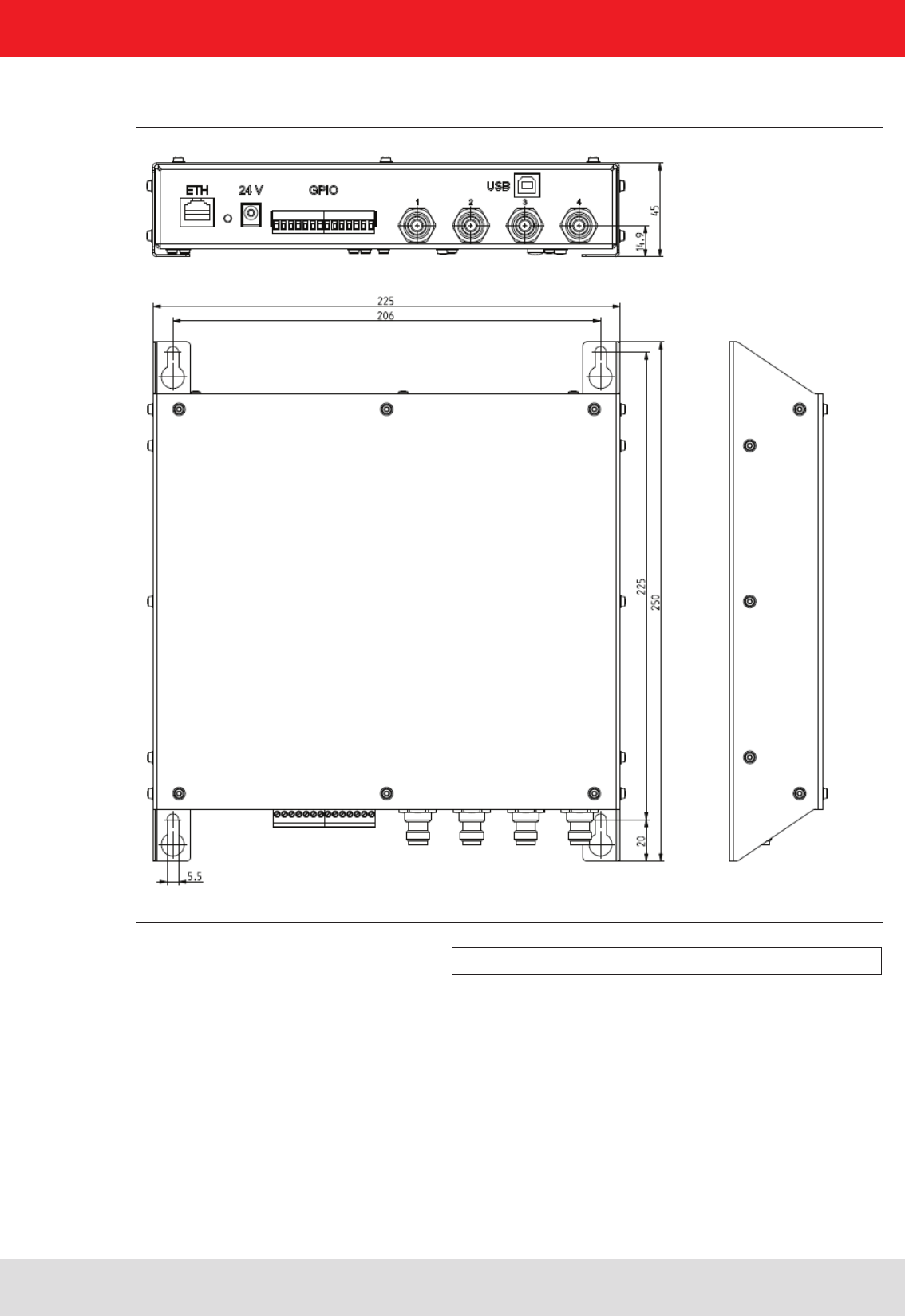
Figure: Far side RRU4 with dimensions
(M6 x 10 screw)
3.1. Selecting the installation site
When the connections are plugged in, the device satises the protection class IP65 (RRU and ARU) and class IP40
(ERU and RDR).
When selecting the installation location, make sure there is sufcient space around it for appropriate dissipation of the heat
generated by the device. Do not install it close to external sources of heat. The maximum operating temperature listed in the
data sheet must not be exceeded. The support surface must have a sufcient lead-bearing capacity/strength.
3.2. Installing the reader
The device has threaded holes at the rear for attaching the reader. The dimensions of the holes pattern can be
found in the drawing below. For ease of installation a bracket is available as an accessory, which offers the option of
mounting on a mast or wall.
3. Installation
Installation manual Reader 17
Modications, misprints and errors excepted
English
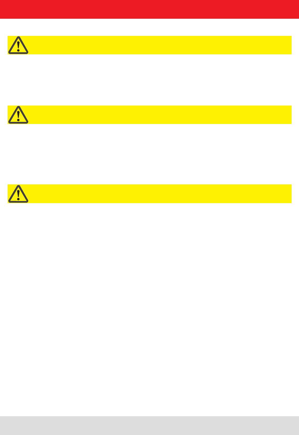
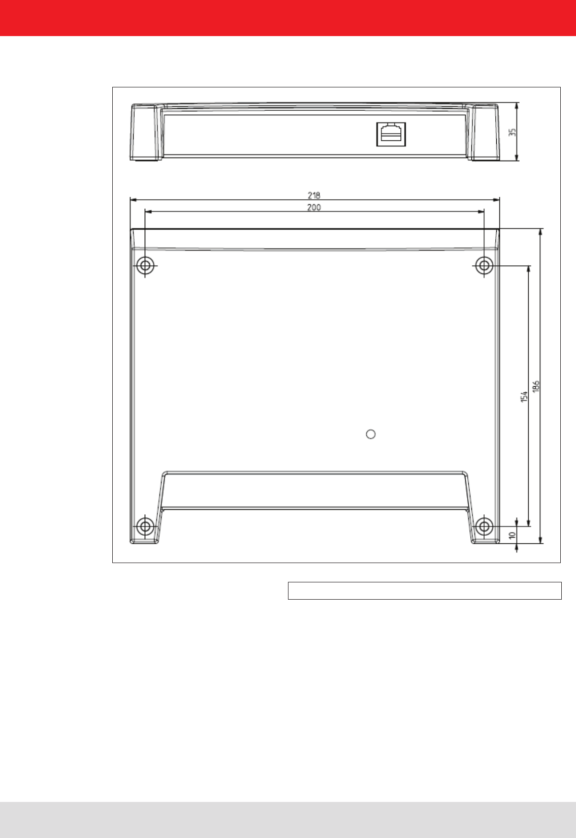
Figure: ERU with dimensions
3.3. Installing the reader ERU
3. Installation
Installation manual Reader 18
Modications, misprints and errors excepted.
English
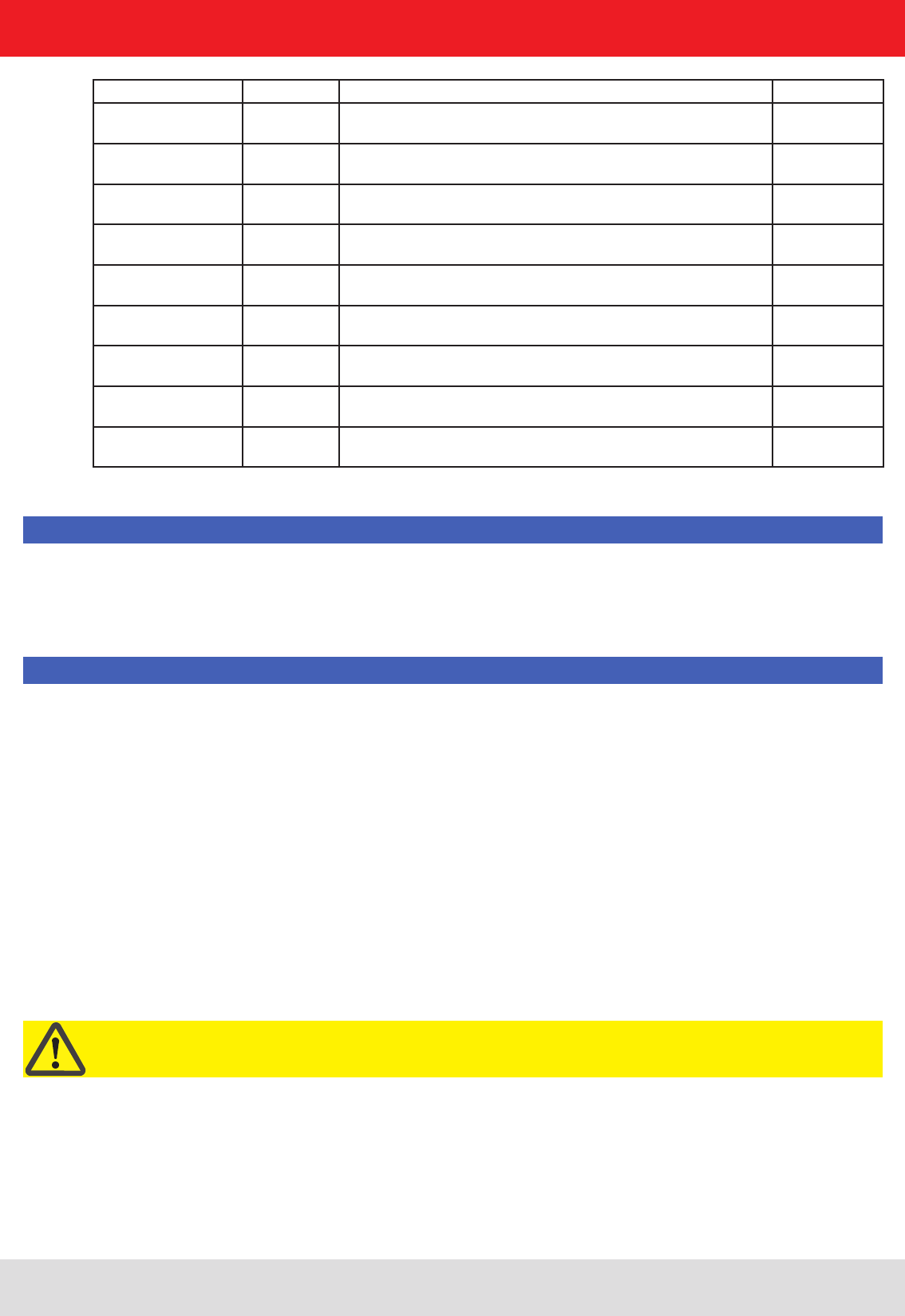
Figure: RDR with dimensions
3.4. Installing the reader RDR
3. Installation
Installation manual Reader 19
Modications, misprints and errors excepted
English
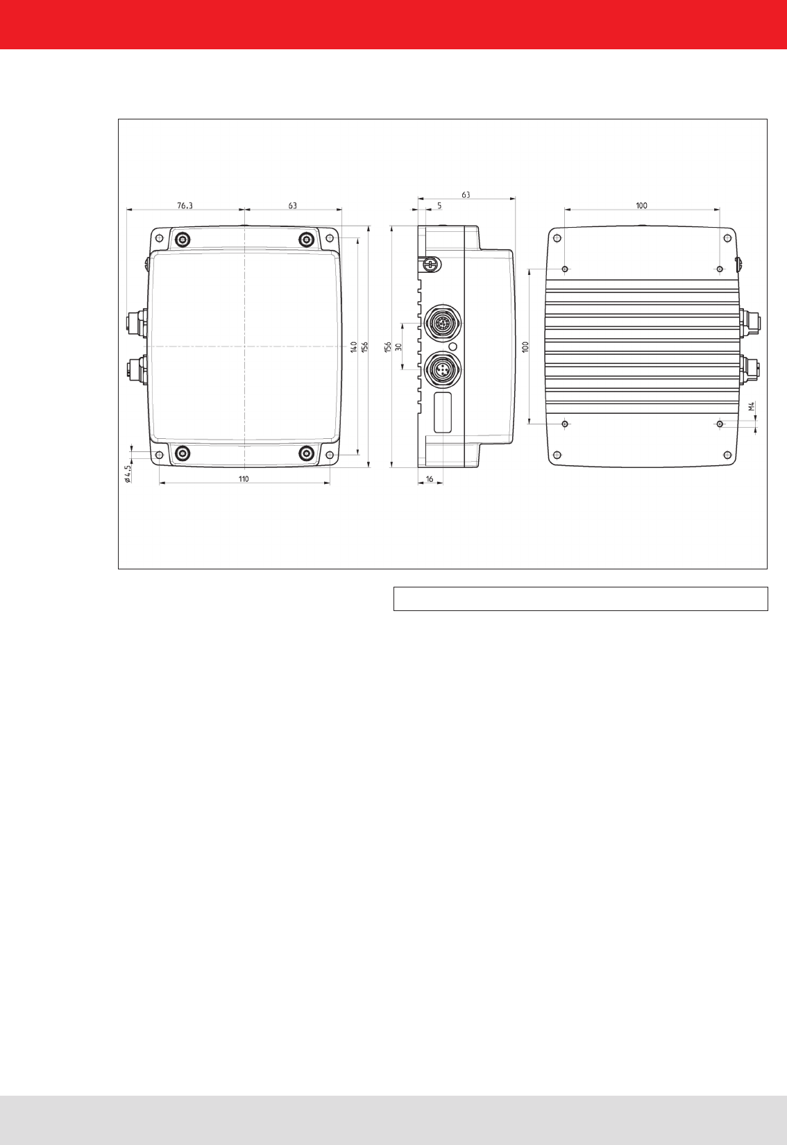
Figure: M-ARU with dimensions
3. Installation
3.5. Installing the reader M-ARU
Installation manual Reader 20
Modications, misprints and errors excepted.
English
4. Connections and displays
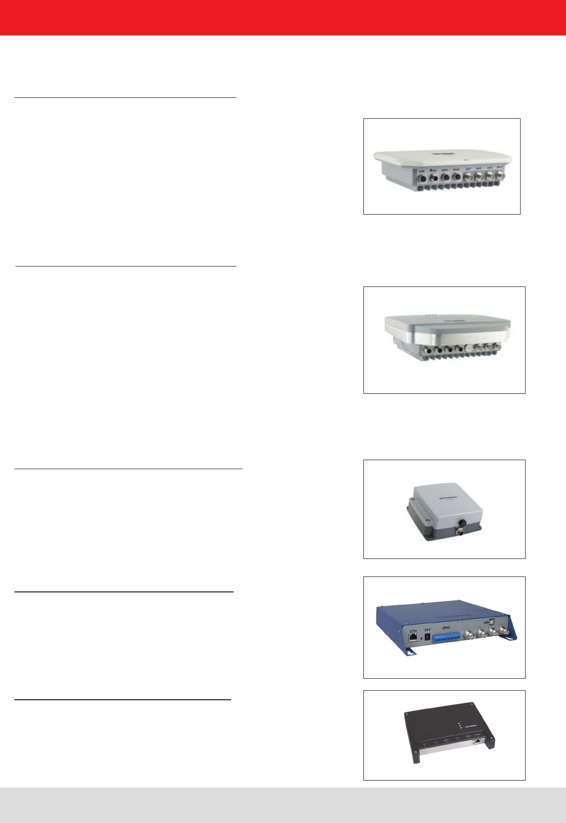
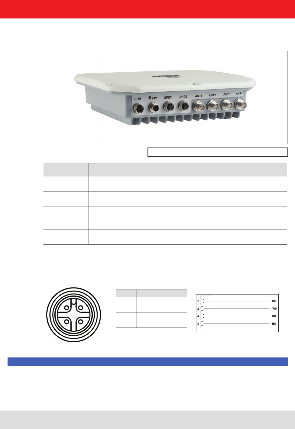
Figure: General view of the RRU4
2 1
3 4
PIN Allocation
1 +24 V DC
2
3 GND
4
Allocation of the power cable (Order-No.. 52010125 und 52010126)
Depending of the device variant, the reader has various connection options. The illustration below shows an RRU
and ARU standard reader with all its connection options. Details of the connections and the pin assignments of plugs
and sockets are provided in the following pages.
Sockets, from
left to right Description
1 Communication connection: M12 (depending on the device variant)
2 Power supply connection: M12 male, 4-pin, A-coded
3 GPIO connection 1: M12 female, 8-pin, A-coded
4 GPIO connection 2: M12 female, 8-pin, A-coded
5 Antenna connection 1: R-TNC 50 Ohm
6 Antenna connection 2: R-TNC 50 Ohm
7 Antenna connection 3: R-TNC 50 Ohm
8 Antenna connection 4: R-TNC 50 Ohm
Status indicators: 3 coloured LEDs (red, green, orange)
4.1. Power supply
The power supply is arranged as a four-pin round-pin plug with and M12 connection thread in A-coding.
Only power supply units with power limitation are approved for operation with the device. This means that the
secondary side of the power supply unit is limited to a power of maximum 100 W.
Note
Installation manual Reader 21
Modications, misprints and errors excepted
English
PIN Allocation
1 TD+
2 RD+
3 TD-
4 RD-
1 2
4 3
PIN Allocation RS422 Allocation RS485
1 RxD+ RxD/TxD+
2 RxD- RxD/TxD-
3 TxD+
4 TxD-
5 GND GND
1 2
4 3
5 Zentral-Pin
PIN Allocation
1 CTS
2 RxD
3RTS
4 TxD
5 GND
1 2
4 3
5 Zentral-Pin
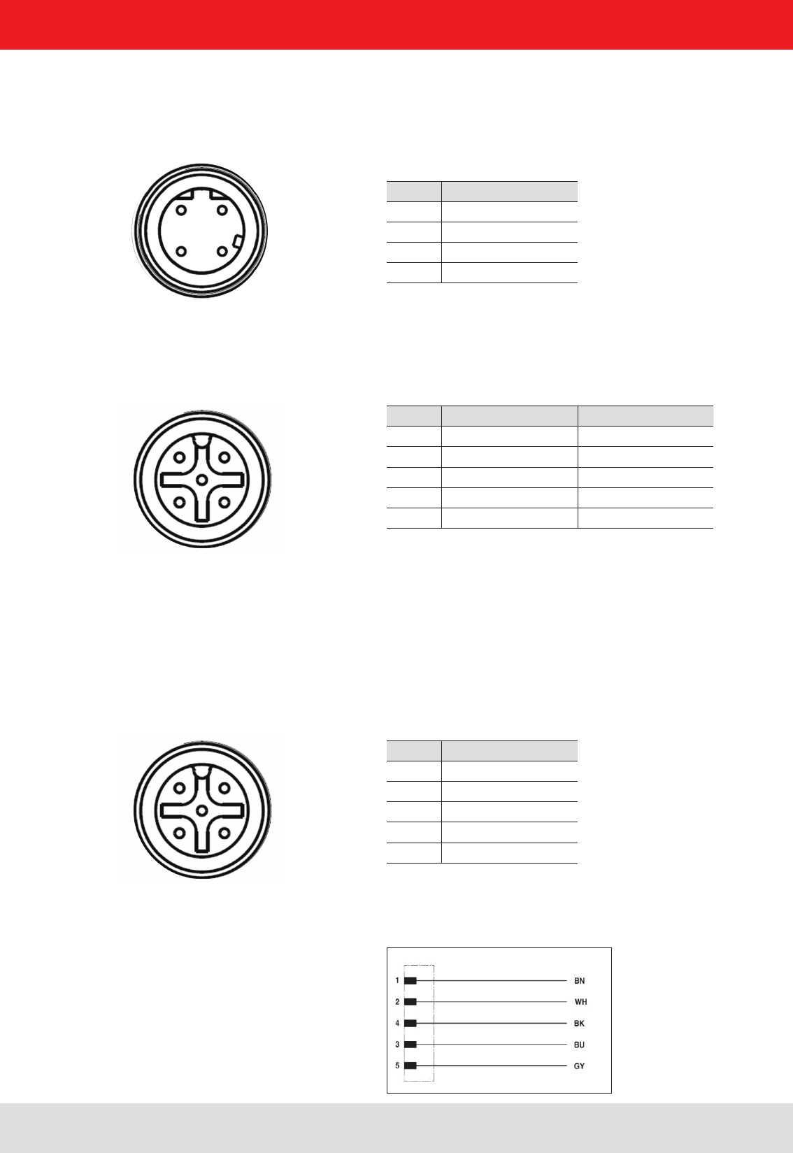
Allocation of the serial interface cable (Order-No. 52010125) valid for RS232, RS422/485
4. Connections and displays
4.2. Ethernet connection
This data interface is arranged as a 4-pin M12 socket with D-coding. Only shielded cables may be used.
4.3. RS422/485 connection
This interface is arranged as a 5-pin M12 socket with A-coding. Only shielded cables may be used.
The interface card of the reader is equipped with a combined RS485/RS422 interface. The changeover between
RS485 and RS422 is performed using the conguration tool. For operation as RS422, the RS485 cables
are connected to RX.
4.4. RS232 connection
This interface is also arranged as a 5-pin M12 socket with A-coding. Only shielded cables may be used.
Installation manual Reader 22
Modications, misprints and errors excepted.
English
4. Connections and displays
4.5. ERU connection
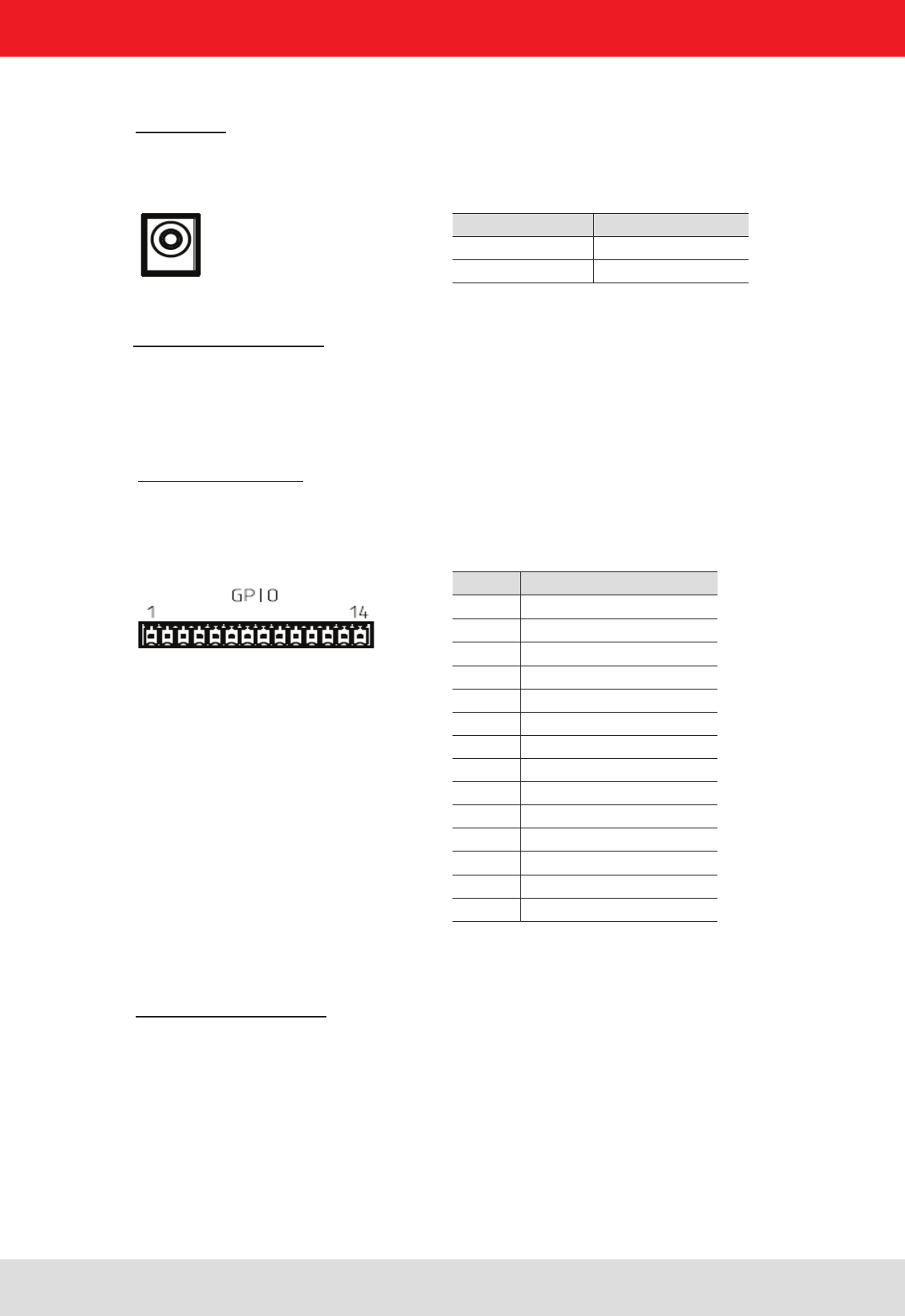
PIN Allocation
1 power supply +
2 Masse
3 INPUT_0
4 INPUT_1
5 INP_COMMON
6 INPUT_2
7 INPUT_3
8 power supply +
9 Masse
10 OUTPUT_0
11 OUTPUT_1
12 OUTPUT_COMMON
13 OUTPUT_2
14 OUTPUT_3
Power supply:
The power supply is designed as a hollow connector 2.5 mm.
Digital inputs and outputs:
The digital inputs and outputs are provided via a fourteen-pin terminal block. The control and evaluation are
provided by the internal software.
Port communication interface:
To communicate with the reader, the ERU Ethernet connection via a standard RJ45 connector can be used.
Alternatively, the reader can ERUs through a standard USB type. B port can be controlled.
4.6. RDR connection
Port communication interface:
To communicate with the RDR reader a Power over Ethernet (PoE) connection via a standard RJ45 connector is used.
PIN Allocation
inner conductor +24 V
outer conductor Masse
Installation manual Reader 23
Modications, misprints and errors excepted
English
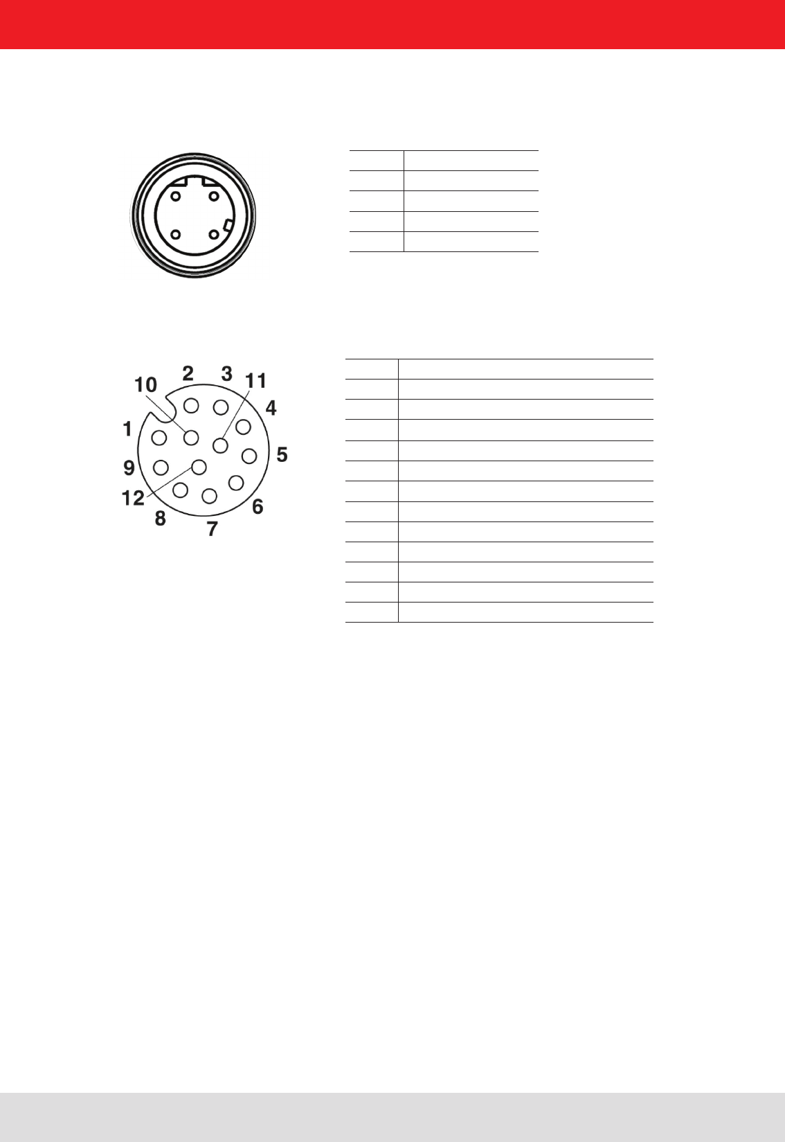
4.7. M-ARU connection
4. Connections and displays
Supply voltage PoE:
PIN Allocation
1 GPIO – OUT3
2 GPIO – GND
3 GND
4 RS 232 – GND
5 RS 232 – RxD (mit TxD vom PC verbinden)
6 RS 232 – TxD (mit TxD vom PC verbinden)
7 + 24 V DC
8 GPIO – OUT2
9 GPIO – IN3
10 GPIO – OUT1
11 GPIO – IN2
12 GPIO – IN1
Supply voltage local GPIO/RS232/Ub
PIN Belegung
1 TD+
2 RD+
3 TD-
4 RD-
1 2
4 3

Installation manual Reader 24
Modications, misprints and errors excepted.
English4. Connections and displays
4.8. UART transmission (RS232, RS422, RS485 or similar)
4.8.1. Bit transmission layer (physical layer)
A full or half-duplex connection such as RS232, RS422 or RS485 is used for the physical layer.
4.8.2. Data link layer
Transmission is in frames and blocks. A block comprises a maximum of 256 frames. A frame comprises a
maximum of 256 bytes, of which a maximum of 250 bytes can be user data. The result is a maximum block size of
64000 bytes of user data.
The data link layer is used to safeguard the data between sender and recipient. The sender receives a response
from the recipient for each frame received. If the sender does not receive a response from the recipient within a
time window of 350 milliseconds after sending a frame, the frame sent is repeated until the error counter signals
the cancellation of the transmission.
4.8.2.1. Structure of a frame
5A LL SS FF DD ... DD P1 P2
5A: Start code for synchronisation
LL: Number of bytes in the frame not including the start code
SS: Status byte
FF: Frame number
DD: User data
P1: 16-bit checksum low byte
P2: 16-bit checksum high byte
4.8.2.2. Start code and synchronisation
The start code is used to synchronise the recipient to the sender. It further allows the receiver to synchronise to the
start of a frame when no data have been received for 15 milliseconds.
4.8.2.3. Status byte
The status byte has the following signicance:
50: Data packet
A0: Response: “OK”
A1: Response: “Memory error” (the receiver was unable to allocate any memory for the data block received)
A response is only 3 bytes long and is not CRC checked.
“OK” response: 5A 02 A0
“Memory error” response: 5A 02 A1
4. Connections and displays

Installation manual Reader 25
Modications, misprints and errors excepted
English
4. Connections and displays
4.8.2.4. Frame number
The frame number denes how many more frames there are in this data block. Only the rst frame in a data block
can be shorter than 256 bytes. Each additional frame must have a length of 256 bytes (length byte LL is FF).
It is therefore possible to calculate the block size from the rst frame number.
For example:
A block with 700 bytes of user data is to be transmitted. For this purpose the block is divided into three frames.
1. frame: 5A CD 50 02 – there now follow 200 bytes of user data – P1 P2
2. frame: 5A FF 50 01 – there now follow 250 bytes of user data – P1 P2
3. frame: 5A FF 50 00 – there now follow 250 bytes of user data – P1 P2
The receiver can use the frame number of the rst frame (here 02) and its length byte to calculate the block size
(block size = frame number * 250 bytes + length byte -5) (here in the example: 2 * 250 bytes + 205 bytes - 5 bytes =
700 bytes), and reserve an appropriate amount of memory for the data.
4.8.2.5. User data
User data are the bytes in a frame that ow into the block transmitted.
4.8.2.6. Checksum
The checksum is calculated using the polynomial x^16 + x^12 + x^5 + 1 with a pre-initialisation of 0x0000 from the
start code to the last user data byte.
4.8.3. Network layer
As the KBRP is a point-to-point protocol, there is no network layer.
4.8.4. Transport layer, session layer, presentation layer
Do not exist.
4.8.5. Application layer
The application layer transmits data blocks from 1 to a maximum of 64000 bytes.
4. Connections and displays

Installation manual Reader 26
Modications, misprints and errors excepted.
English4. Connections and displays
4.9. LLRP-Protocol
Note
Based on the communication protocol TCP, the Kathrein RFID reader with the Linux
operating system can handle the so called Low Level Reader Protocol (LLRP).
This is a by EPCglobal (http://www.epcglobalinc.org/standards/llrp) standardized com-
munication interface between RFID reader and a LLRP-enabled application software.
The default port for LLRP is 5084.
This LLRP protocol is roughly divided into the following parts:
• Automatic query of the reader functions by the application software
• Conguration of the reader functions by the application software
• Triggering of read and write operations on the air interface by the application
software
• Transfer of the found tag data to the application software
To start the LLRP application, please use the AppManager of the ReaderStart Sw.
There you can load the LLRP protocol engine with „Install App“ then start with „Start
App“.
To test the Kathrein reader with the LLRP protocol you can use the open-source pro-
gramming tool „Eclipse (IDE)“. With the so called LLRP Commander the Reader can
be controlled and operated.
Eclipse (IDE) and LLRP Commander are not part of the Kathrein RFID SW
Installation manual Reader 27
Modications, misprints and errors excepted
English
4.9. LLRP-Protocol
4. Connections and displays
4.11. Digital inputs and outputs
4.10.1. Frame structure
A frame is structured as follows:
Start + Data block + End
The start consists of 0xAA 0xBB 0x01 0x01, where the rst 1 is the data transmit byte and the second 1 a stuff byte.
The end consists of 0xAA 0xCC. If the byte 0xAA occurs in the KBRP frame, it must be doubled (0xAA → 0xAA 0xAA)
4.10.2. Port
The TCP communication port is the Port 4007.
4.10.3. Example
As an example the frame for “ASyncGetEPCs” is shown. The ID for this command is the “0x0111” which then causes
the frame to appear as follows:
0xAA 0xBB 0x01 0x01 0x11 0x01 0xAA 0xCC
4.10. Ethernet transmission
When communication to our reader is via Ethernet, a data transmission layer is also used, as for serial communication.
The transmission layer via Ethernet looks much simpler here, because the TCP/IP protocol already provides a
data security layer. All we need to add are the packet start and packet end, since TCP/IP is a streaming protocol.
The activation and evaluation can be performed using the software ReaderStart v2, with the DLL supplied, or by
access to the reader protocol.
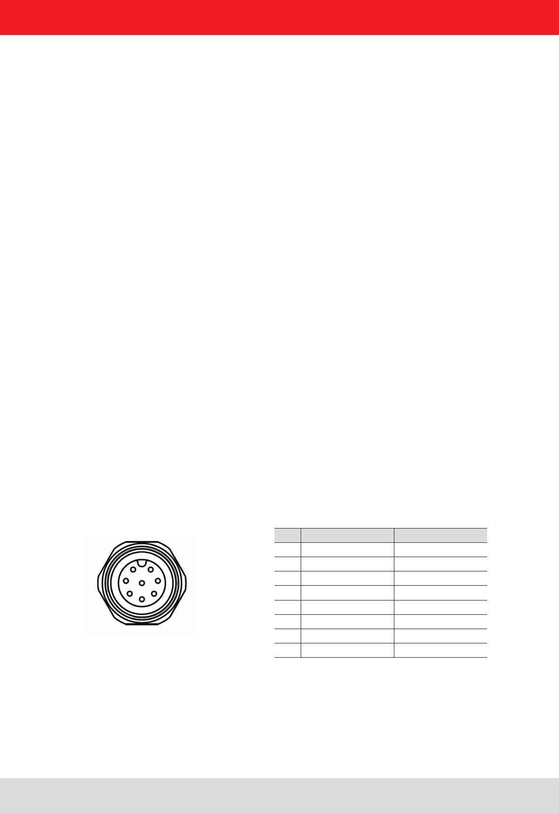
Pin GPIO 1 GPIO 2
1 OUT_CMN OUT_CMN
2 INPUT 4 INPUT 1
3 INP_CMN INP_CMN
4 GND GND
5 UB UB
6 OUTPUT 4 OUTPUT 2
7 OUTPUT 3 OUTPUT 1
8 INPUT 3 INPUT 2
1 2
7 3
6 4
5
8 central pin
Installation manual Reader 28
Modications, misprints and errors excepted.
English
4. Connections and displays
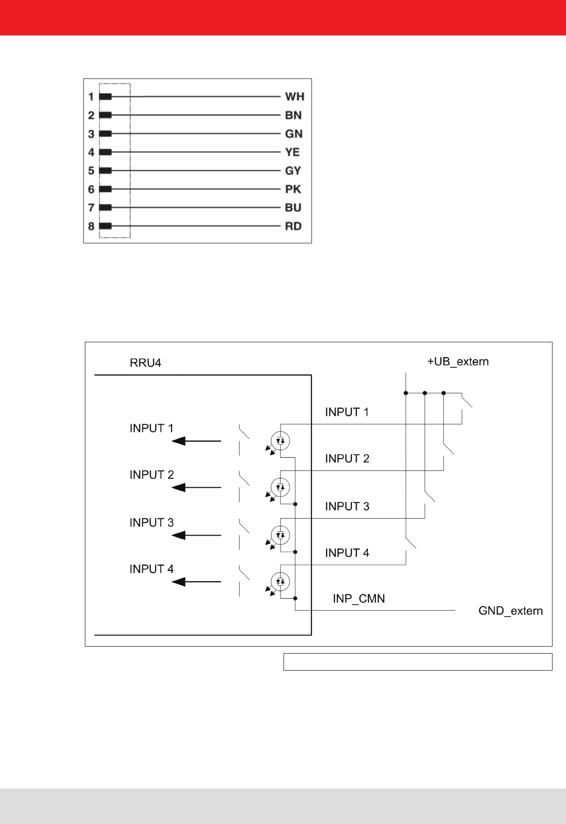
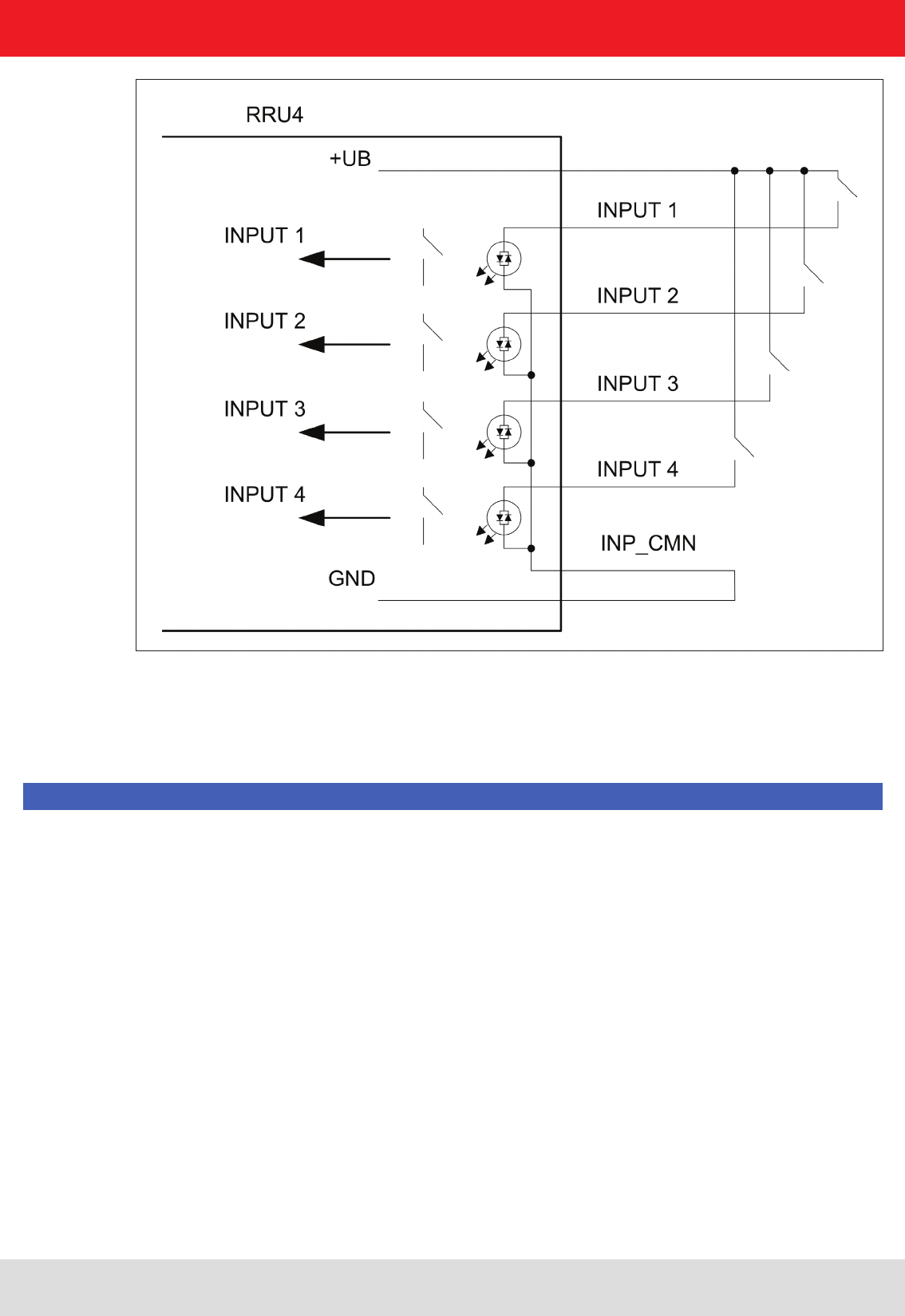
Allocation of the GPIO interface cable (Order-No. 52010125, 52010126)
The digital inputs and outputs are communicated via two eight-pin sockets in A-coding with M12 connection
threads. The inputs are double isolated from the power supply of the reader and can be operated irrespective of
the polarity of the input signal. For this reason there is a common pin for the inputs (INP_CMN). The connection
variants for the inputs are shown below. Depending on the application, the power to the inputs can be double insulated
from the external power supply to the reader, or not double insulated from it.
Figure: Inputs double insulated
Installation manual Reader 29
Modications, misprints and errors excepted
English
4. Connections and displays
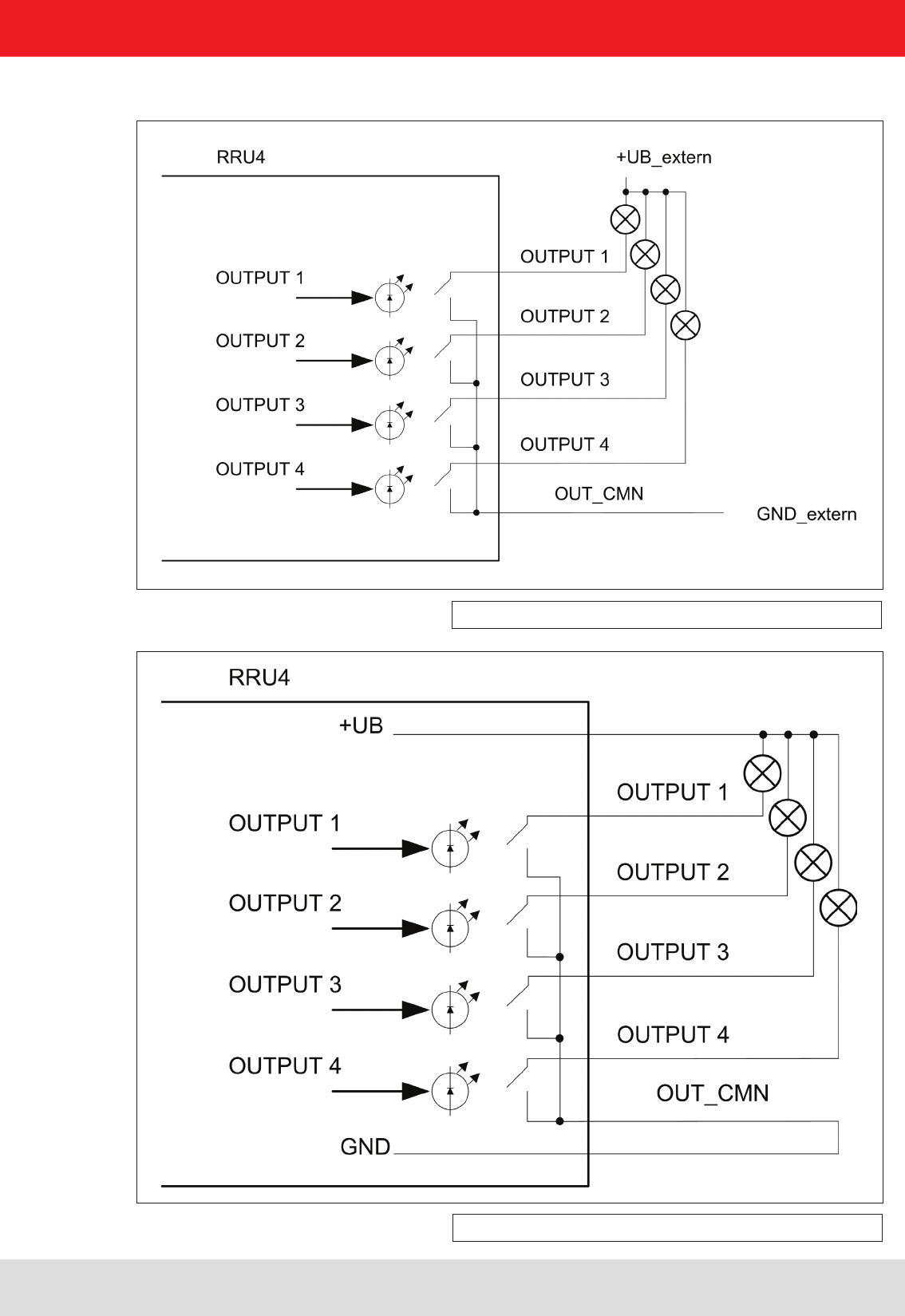
The outputs are also double insulated from the power supply to the reader and have a common pin (OUT_CMN).
If the double insulation is not required, the power supply can also be taken directly from the reader.
Please note that the load per channel is limited to a maximum of 0.5 A, and the total load across all the channels
must not exceed 1.5 A. The inputs and outputs are designed for a maximum voltage of 30 V DC. Further information
can be found in the data sheet for the reader.
Note
Installation manual Reader 30
Modications, misprints and errors excepted.
English
4. Connections and displays
The connection examples for the outputs are shown in the next illustrations.
Figure: Outputs double insulated
Figure: Outputs not double insulated

Installation manual Reader 31
Modications, misprints and errors excepted
English
4. Connections and displays
4.12. Antenna Connection
4.13. LED
4.14. Buzzer
For the connection to the RFID antennas, the reader has four antenna connections that are of reverse
TNC design. Please only use the cable from the accessories or equivalent cable for this connection.
Note
Please only use cable suitable for the impedance (50 Ohm), as otherwise the performance of the reader will be
severely limited by the mismatch. If the mismatch is large, the reader may indicate a fault.
The reader has a 2-colour LED for the indication of the operating state. The table below shows the colours used
and the related operating state.
Red Green Operating state
Xashes approx. every 8 seconds Error during initialisation
X X Unit is booting
Flashes approx. every 8 seconds X Normal operation with heartbeat
The reader has also ARU4 the antenna dome 4 LEDs. (Red / green / red / green) that can be controlled via software
Table: Indication of the operating states by the LED
Furthermore the reader is also tted with a buzzer which, in addition to the LED, indicates successful booting
(1 x short) or an error (2 x long).
Installation manual Reader 32
Modications, misprints and errors excepted.
English
5. Software
Figure: Installation Language
The splash screen is now appearing again information
about the exact state of the versionReader Start software.
This information can later be retrieved via the drop-down
menu in the menu bar info.
Figure: Welcome screen with software version
The presentation of the setup window depends on the operating system.
The following pictures show the state to install with software version 2.20. All subsequent versions are also installed.
Please follow the instructions on the screen.
For test purposes the reader can be operated using the demo software supplied. This software provides all the
necessary functionality of the reader for a test in a real environment. As an aid to conguration, various basic
settings for application scenarios are provided.
The current version of the Reader Start can be found on our website under „Software & Downloads“.
As well as this documentation, the following documents and programs can be found on the CD supplied:
- data sheet for the reader
- specication of the protocol for communication by the reader with a receiver
- catalogue of the RFID products currently available
- API DLLs for the simplied activation of the reader with Borland and Visual Studio together with some simple
programming examples
- set-up program for the Kathrein reader start demo
- .Net Framework 4
- C++ 2008 redistributable
5.1. System requirements
To ensure correct operation using the software on your PC/laptop, your PC/laptop should meet the following
minimum requirements:
Processor: X86 compatible
Memory: 512 MB RAM
Operating system: Windows XP (SP3), Vista (SP1), Windows 7 or higher
free hard disk memory for:
32-bit operating system 850 MB (including Microsoft .Net Framework 4)
64-bit operating system 2 GB (including Microsoft .Net Framework 4)
5.2. Installation
The demo software is installed by running KathreinRFIDDemoSetup.exe from the CD-ROM supplied. During
the installation a check is made whether the necessary preconditions for the installation are satised. This
means that a check is made whether all the dependencies such as the necessary Windows Service Packs, the
.NET Framework in the respective version together with the C++ redistributables are installed. If this is the case,
during this process the demo software and the DLL for controlling the reader are installed.
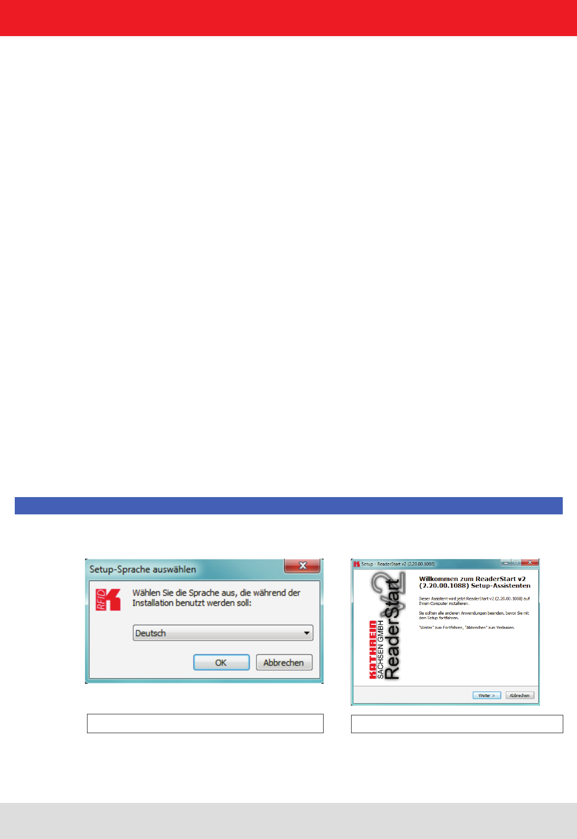
After the start of the set-up, you can change the language used during the installation in the window that now opens.
Conrm your selection by clicking on the OK button.
Note
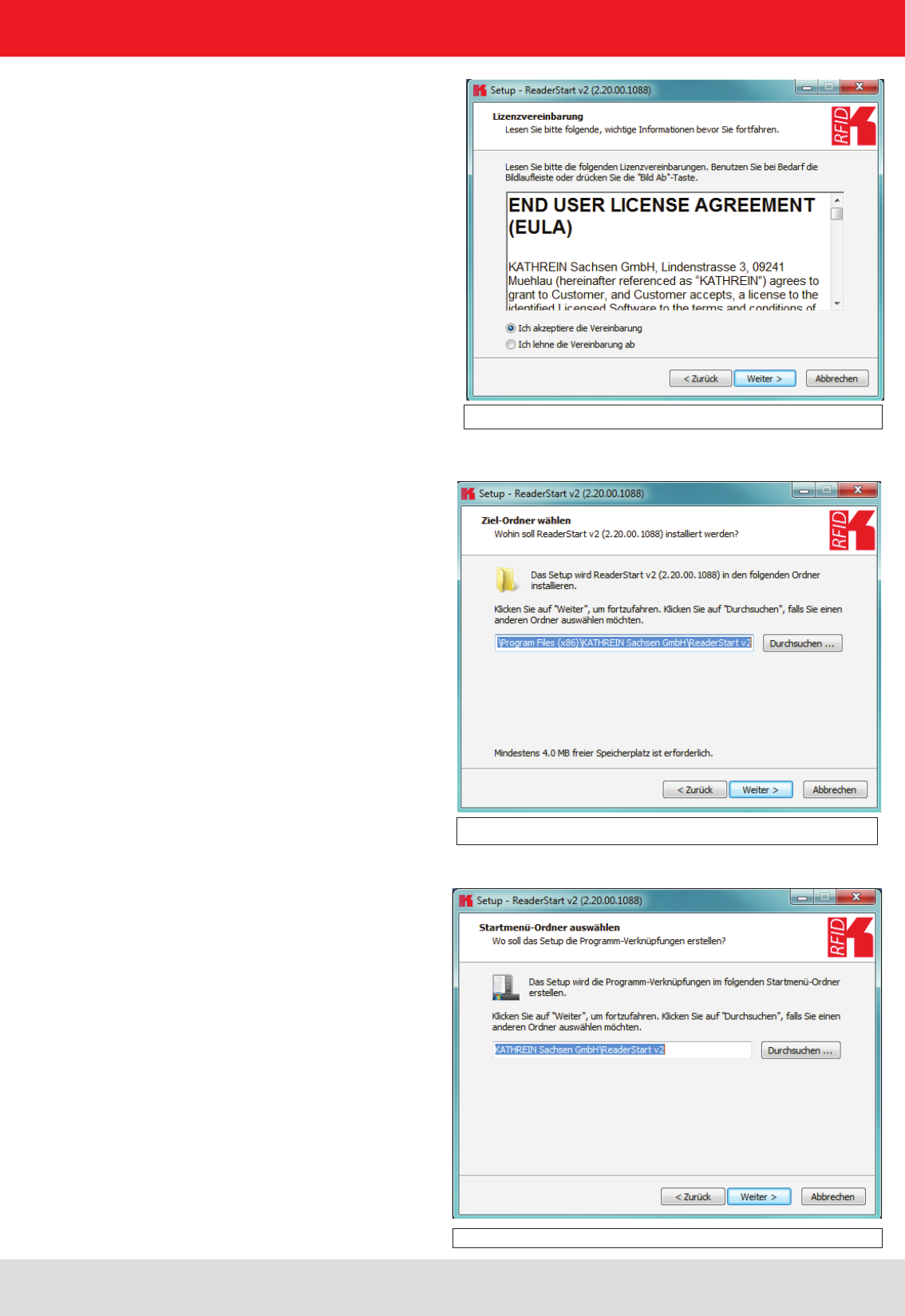
Clicking on the Next button takes you to the license
agreement. Please read this through carefully; if you do
not accept the terms of the agreement you must
decline to accept it. The installation is then terminated
at this point.
Installation manual Reader 33
Modications, misprints and errors excepted
English
Figure: Conrmation of the license agreement
5. Software
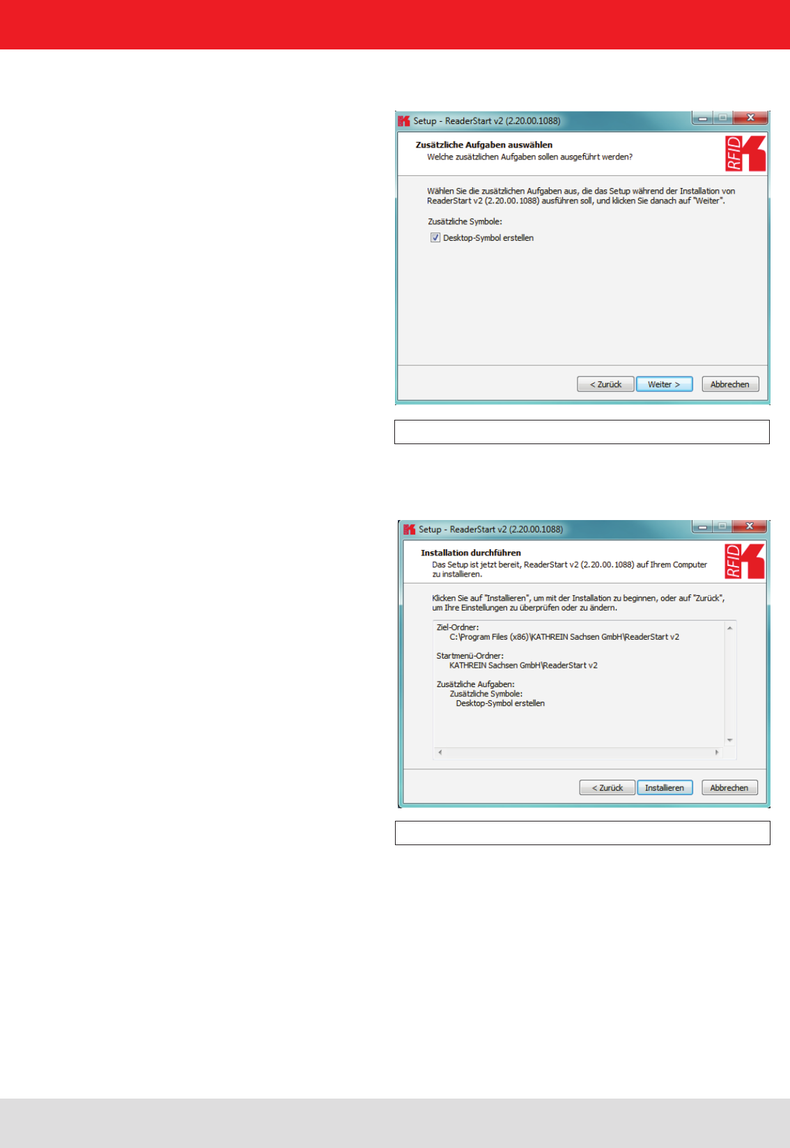
Figure: Selection of the installation folder
Figure: Selection of the folder in the start menu
In the next screen you can customise the folder in the Windows start menu. Here, as in the previous windows,
you are offered the standard settings.
If you have accepted the license agreement, press the Next button, following which you can select the target folder in
which to install the software. Don't forget to select the target drive also.
Installation manual Reader 34
Modications, misprints and errors excepted.
English
5. Software
Figure: Selecting installation tasks
Figure: Summary of the installation tasks
In the following window you can specify whether you wish an icon to be included in the Windows Quick Launch
and/or on the Desktop. The default is to generate no icons.
Finally a summary of all the installation tasks is shown. Click on the Install button to start the
installation. If during the installation procedure a request is made to restart the computer, please do so.
Installation manual Reader 35
Modications, misprints and errors excepted
English
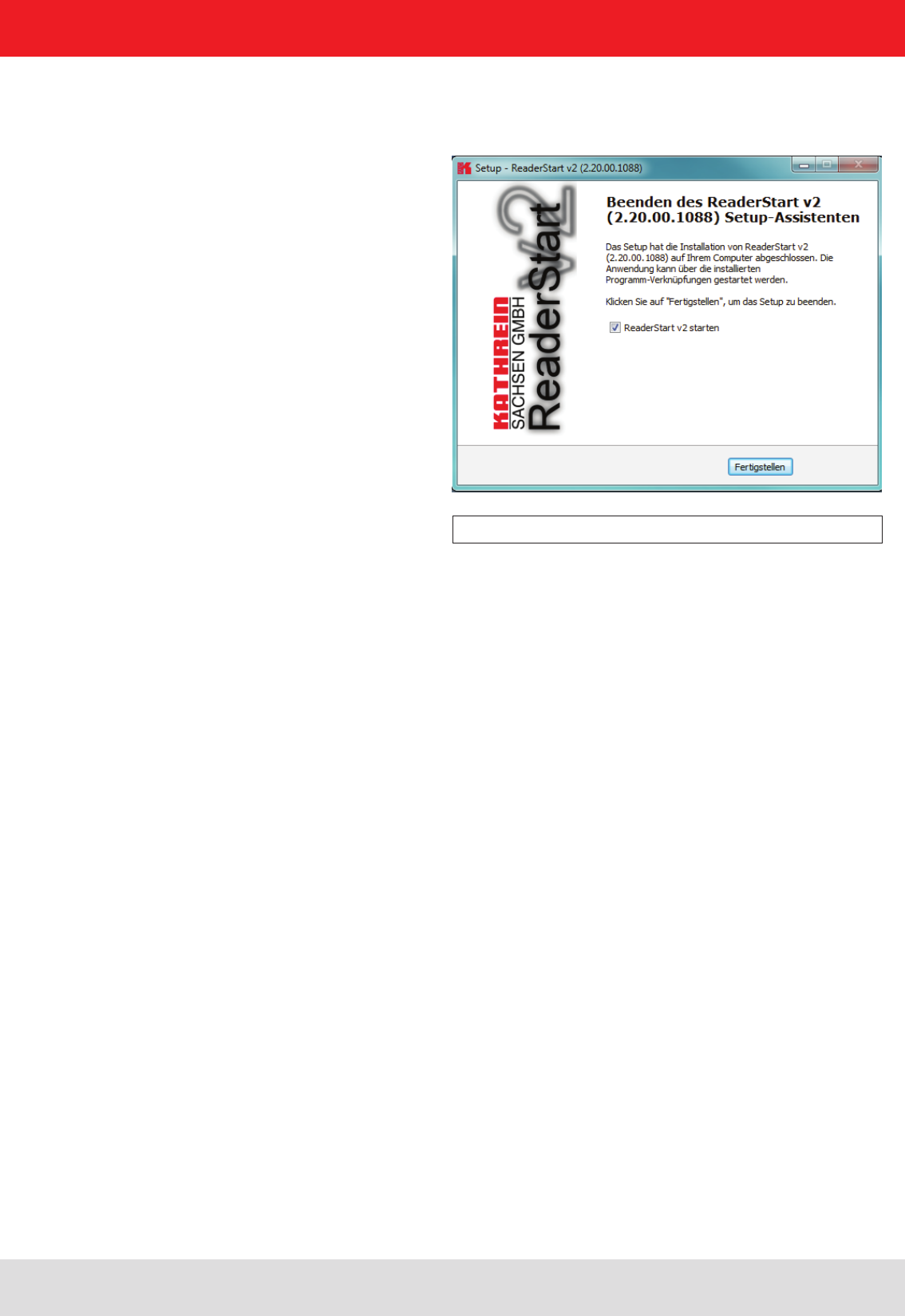
Successful completion of the installation is shown in the following window. If you do not wish to start using the
software straight away, please uncheck the Launch ReaderStart v2, box, otherwise the program will start immediately
once you click on Finish
5. Software
Figure: Completing the installation
Installation manual Reader 36
Modications, misprints and errors excepted.
English
5. Software
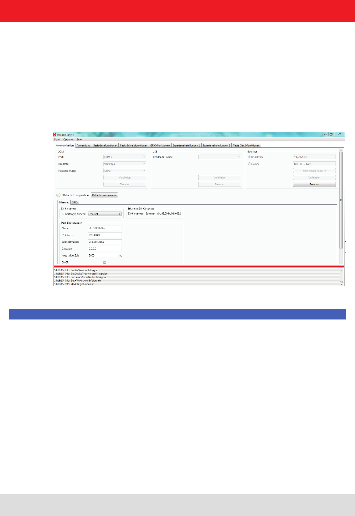
5.3.1. User interface for ReaderStart v2
Bild: Oberäche ReaderStart v2
5.3. Operation
In the following section, the Reader‘s launch software for the Kathrein RFID reader is described.
The program is started by ReaderStart v2.exe. The splash screen is displayed until all the necessary DLLs have
been loaded in the background. After this the user interface shown below appears. This consists essentially
of the menu bar, the tabs together with the status eld.
The insertion of of the tab („App Manager“) is then only when the reader hardware supports it.
Note
Functions that are unavailable are greyed out in the program.
The settings and controls for the reader are divided into individual functional groups under different tabs.
The individual sheets can be selected using the tabs. The sequence of the tabs can be changed as required by
“drag and drop”.
All status messages from the reader and the program are shown in the status eld, and if desired logged. 3 message
types are dened:
• Info – shows which action was just performed
• Warning – indicates possible problems in the structure and conguration
• Error – indicates that the desired action could not be executed
Every message is provided with a time stamp which is placed in the status eld which always lies above the
information itself.
Installation manual Reader 37
Modications, misprints and errors excepted
English
5. Software
Figure: Saving the conguration in a le
5.3.3. Menu bar
The menu bar allows the program to be customised to your own requirements. These include for example:
language settings, layout, status messages and calling up the program information. It consists of the items: le,
options and info.
5.3.3.1. File
There are a wide variety of parameters available for conguring the RF front end. A complete setting can be saved
as a parameter set in the menu item le as an XML le, and later reloaded.
Under the item Save Reader Conguration to File, a dialogue opens which displays all the available parameter sets
(0 - 7). The selection can be changed by setting the check. Furthermore each parameter set can be described briey.
Selecting Save opens a further dialogue in which a respective save location and a le name must be selected or input,
in order to successfully save the le. The progress of the save operation is shown by a progress bar.
The status eld has a context menu which allows deactivation of warnings, information and errors in the status eld. Messages that
have expired can be deleted in this menu.
Reloading the settings starts with the selection of the parameter le. In the dialogue which opens, all available parameter
sets are displayed. The assignment of them to the individual save locations can be reassigned here. For this purpose
the desired parameter set on the reader can be selected in the drop-down menu. Selection of the item None means
this parameter set is not loaded into the reader. In the default setting a 1:1 assignment applies. Pressing the Assign
parameter sets 1:1 button resets all the changes in the assignment to the default. Pressing the Delete assignment
button deletes all assignments of the saved parameter sets to those in the reader. In the drop-down menu this is
indicated by None.
Installation manual Reader 38
Modications, misprints and errors excepted.
English
5. Software
Figure: Loading a conguration from the le
5.3.2.2. Options
Figure: Changing the language
The Options are divided into two groups. One part offers the facility to change or reset some properties
of the program. The second part permits the reader to be provided with new rmware and to change its system time.
The rst group includes changing the language, selection of the warnings that are displayed, resetting the layout
and deletion of the status messages in the status eld. The language used in the program set to the desired
language by clicking on Language Selection in the menu item. The currently selected language is shown
by a check; if a computer restart is necessary in order to load the change, the program will indicate this.
Installation manual Reader 39
Modications, misprints and errors excepted
English
5. Software
Figure: Setting the warnings
Figure: Updating the rmware
Figure: Setting the date and time
Under the item Warnungen (Warnings), the conrmation queries for the actions Describe, Block or Deactivate the
tags in the eld are activated or deactivated.
Note
Changing the memory content of the tags can render them unusable.
If it is desired to recreate the original layout of the program in respect of window size and sequence
of tabs, this can be achieved by means of the Reset layout menu item.
The Firmware Update item permits the update of the reader rmware. The window that opens shows the version
currently mounted in the reader. After selection of a rmware le, this version is shown in the next line. Pressing the
Update button starts the procedure. The progress is shown in the Update progress line in a bar. After a successful
update the reader must be restarted, either by pressing the Restart button or by switching the power supply off and on
again.
The reader has an integral clock, which can deliver the time stamp for a tag operation. This clock is set using the Date and
time settings in the menu. When this menu item is opened, it automatically reads the current date and time from the reader
and compares this with the date and time from the host computer. The date and time of the host computer can now be
loaded to the reader by pressing the Set system date and time on Reader button. There is also the facility to set the reader
date and time manually and load it to the reader. This is done by entering the desired date and time on the reader side and
pressing the Set adjusted system date and time on Reader button. The status line indicates which action was just executed
and whether the action was successful.
Installation manual Reader 40
Modications, misprints and errors excepted.
English
5. Software
5.3.2.3. Info
Figure: About reader start v2
Figure: Displaying the license key
Figure: Interrogating information about the reader
This item on the menu bar allows information about the reader start software and the reader to be interrogated.
The version issue of the PC software can be interrogated under the rst item.
The second item automatically reads the license key. The key plays back various factory-set parameters of the reader.
In certain cases it may be necessary to send this key to Kathrein (rd@kathrein.de). The window that opens allows the
key to be copied to the clipboard.
The third item supplies detailed information about the software and hardware versions of the reader. The rmware is
specied with version number and build number. The hardware issue is divided into CPU module, PA module and the
various I/O modules. The information about the I/O modules are stated in the format Insert position : module type .
The Error status item reads the error status of the reader and shows all errors that are still outstanding in the status eld.