KATHREIN Sachsen ARU4ELCU6 UHF RFID Reader User Manual Antennas
KATHREIN Sachsen GmbH UHF RFID Reader Antennas
Contents
User Manual Antennas

English
Installation manual for
Kathrein RFID UHF-Antennas
Installation manual antennas
Version 2.52
This document is valid for all Kathrein RFID antennas and describes the construction and the
installation of the antennas.
Low Range Antennas
Mid Range Antennas
SMSH Antennas / -modul
SMSH © KRAI Antennas / -modul
Wide Range Antennas
Wide Range © KRAI Antennas
date of creation: 01.06.2012
Document No. 936B059
Installation manual antennas 2
Modications, misprints and errors excepted
EnglishInstallation manual antennas
RFID-UHF-Antennas
Type: Order number:
U-LoRa ETSI/FCC; Ultra Low Range antenna ETSI/FCC, 865-928 MHz 52010092
LoRa ETSI; Low Range-antenna ETSI, 865-870 MHz 52010084
LoRa FCC; Low Range-antenna FCC, 902-928 MHz 52010085
Type: Order number:
MiRa ETSI; Mid Range antenna ETSI, 865-870 MHz, 100° circular 52010082
MiRa FCC; Mid Range antenna FCC, 902-928 MHz, 100° circular 52010083
S-MiRa ETSI/FCC; Short-Mid Range antenna ETSI/FCC, 865-928 MHz, 100°
circular
52010172
Type: Order number:
SMSH-30-30-antenna modul without protective cover 52010219
SMSH-30-30-KRAI-antenna with protective cover 52010258
SMSH-HighGain-30-30-KRAI-EU-antenna with protective cover 52010259
SMSH-HighGain-30-30-EU-antenna modul without protective cover 52010260
Type: Order number:
WiRa 70° ETSI; Wide Range antenna ETSI, 865-870 MHz, 70° circular 52010078
WiRa 70° FCC; Wide Range antenna FCC, 902-928 MHz, 70° circular 52010079
WiRa-70-KRAI-ETSI; Wide Range © KRAI antenna ETSI, 865-868 MHz 52010193
WiRa-70-KRAI-FCC; Wide Range © KRAI antenna FCC, 902-928 MHz 52010194
Type: Order number:
WiRa-40-linear-ETSI; Wide Range antenna 40°/40°, linear, ETSI 52010251
WiRa-40-linear-FCC; Wide Range antenna 40°/40°, linear, FCC 52010252
Type: Order number:
WiRa 30° ETSI; Wide Range-antenna ETSI, 865-870 MHz, 30° circular 52010086
WiRa 30° FCC; Wide Range-antenna FCC, 902-928 MHz, 30° circular 52010087
WiRa-30-CSB-KRAI-ETSI; Wide Range Switch Beam © KRAI antenna ETSI,
865-868 MHz, 30° circular
52010227
WiRa-30-CSB-KRAI-FCC Wide Range Switch Beam © KRAI antenna FCC,
902-928 MHz, 30° circular
52010228
WiRa-30-linear-ETSI; Wide Range antenna 30°/70°, linear, ETS 52010248
WiRa-30-linear-FCC; Wide Range antenna 30°/70°, linear, FCC 52010249
This manual applies to the following RFID UHF types:

Installation manual antennas 3
Modications, misprints and errors excepted
English
Foreword and general information
The reproduction or distribution of this document or extracts from it in whatever form and by whatever means (electronic or
mechanical) for whatever purpose is permitted only with the prior written permission of Kathrein.
Kathrein accepts no liability for omissions or inaccuracies in this document or in relation to the provision or use of the information
contained in this document. Kathrein reserves the right to change the products described in this document and does not accept
any liability in relation to the application or usage of the products described in this manual.
This document and the information contained in it are proprietary information of Kathrein and should be treated as condential.
Kathrein provides this document to its customers in connection with contacts of sale for the products described therein. If the person in
possession of this document, being a legal or natural person, is not a contractual sales partner of Kathrein, or Kathrein has not intended
him by other means as the recipient of the document and the information contained therein, the person in possession is hereby
informed that the use of this document is unlawful and a violation of the rights of Kathrein.
Copyright notice
The information in this manual was correct at the time of editorial deadline.
We reserve the right however to make changes at any time and without prior notice.
This document was prepared for specialist personal who install, congure and place in operation the reader.
Scope
The information contained in this manual is intended for the support of the development process and as development guidance
for the customer. In addition this manual offers supporting information about the standards to be applied at the place of installation
and the relevant safety standards for installation and conguration of the Kathrein reader.
General information
This manual contains information on the installation, conguration, operation and maintenance of the reader. In addition it gives
detailed technical data in order better to familiarise the user with the features of the reader.
In order to ensure a long working life and fault-free operation, this manual should therefore be read carefully and all the instructions
and information contained in it should be complied with.
Warranty
Switching on the AC or DC power supply prior to connecting the LAN cable is considered incorrect installation. Any functional defect
arising as a result is excluded from the warranty/guarantee. Before installing or servicing the reader, the person concerned must
have read the manual and understood its contents. Kathrein accepts no liability if the customer fails to implement the precautions
listed here. In such cases, any claims under the warranty/guarantee are void.
Disposal instruction
Electronic equipment is not classed as household waste and must be disposed of properly in accordance with
Directive 2002/96/EC OF THE EUROPEAN PARLIAMENT AND OF THE COUNCIL of 27 January 2003 on used
electrical and electronic equipment.
At the end of its service life, take this device for disposal at a designated public collection point.
Used batteries are special waste!
Do not put used batteries into your domestic waste; instead take them to a collection point for used batteries!

Installation manual antennas 4
Modications, misprints and errors excepted
English
List of contents
Abbreviatiions used in Application note:
CK Connecting Kit
CSB Circular Switsch Beam
DIN Deutsches Institut für Normung (German Institut for Standardisation)
EIFF Effective Isotropic Field Factor EIFF shows the eld isoltaion from far-
eld to near-eld in realation to the isotropic monopole
EIRP Equivalent Isotropically Radiated Power
EN Europäische Norm (European standard)
ERP Effective Radiated Power
LoRa Low Range
MiRa Mid Range
PoE Power over Ethernet
RFID Radio Frequency Identication
PLS Polarisation Switching
SAR Spezic absorption rate
SMSH SMSH © KRAI planar antenna module
S-MiRa Short Mid Range
UHF Ultra High Frequency
U-LoRa Ultra Low Range
WiRa Wide Range

Installation manual antennas 5
Modications, misprints and errors excepted
English
RFID-UHF antennas 2
Foreword and gernaral information 3
List of contents 4
1. Saefty instruction /-informationen 7
2. Introduction 8
2.1. RFID UHF antennas 8
2.2. Scope of supply 8
2.3. Accessories 9
3. Product description 10
3.1. Low range Antennas 10
3.2. Mid range Antennas 10
3.3. SMSH antennas / -module 10
3.4. Wide range Antennas 11
3.5. © KRAI Antennas 13
3.6. Antenna type according to read range and transponder shape 12
3.7. Maximum reading range 13
4. Technische daten 14
4.1. Ultra-Low range and Low range antenna 14
4.2. Short-Mid range antenna 16
4.3. Mid range antennas 18
4.4. SMSH © KRAI planar antenna module 20
4.5. Wide range 70° antennas 21
4.6. Wide range © KRAI 70° antennas 23
4.7. Wide range 30° antennas 25
5. Installation 27
5.1. Connecting Kit for Reader 27
5.2. Cable laying 27
5.3. Wall/mast clamp 28
List of contents

Installation manual antennas 6
Modications, misprints and errors excepted
English
List of contents
5.4. Assignment Wall/mast clamp to antennas and readerse 29
5.5. Installation drawings 30
6. Contact address 33
Installation manual antennas 7
Modications, misprints and errors excepted
English
1. Safety instructions/information
Key
Caution
Note
Important!
Before starting installation work or replacing the unit, the accompanying manual must be read carefully and its
contents understood.
The detailed information in the data sheets and in this manual must be complied with carefully during installation
and operation of the reader!
The installation team must be properly qualied and familiar with the safety regulations applicable in the country
concerned.
Connection, installation and maintenance work, as well as all other work on the unit, may only be carried out by
properly qualied and trained employees.
The unit may only be used for the purpose intended by the manufacturer.
Unauthorized changes to the unit and the use of spare parts and peripheral devices which are not sold or
recommended by the manufacturer can result in res, electric shocks and injuries. Such actions therefore result in
exclusion of liability and make the manufacturer’s warranty/guarantee null and void.
The applicable version of the manufacturer’s warranty is that which was valid at the time of purchase. We accept
no liability for unsuitable manual or automatic adjustments made to the unit's parameters and inappropriate use of
the unit.
Repairs may only be undertaken by personnel authorised to perform them. Opening or attempting to repair the
unit makes all guarantee/warranty claims null and void! Improper work on the unit may jeopardise electrical safety.
The manufacturer is not liable for accidents caused by the user opening the unit!
When carrying out work on the unit, the valid safety regulations must be complied with.
Supply voltage
Make sure that the mains cable (power supply cable) is not damaged. If the mains cable is damaged, the device
must not be used. Instead it must be disconnected from the mains and repaired by a qualied technician. Use only
the power supply unit supplied!
Risk of fatal injury due to electric shock!
The device may be operated only at the stated supply voltage (see the rear of the device or external power supply
unit)!
If the supply voltage is too high, there is a risk of re!
General safety notes
Important!
Indicates a potentially dangerous situation which, if disregarded, can lead to injuries
ranging from minor to severe and/or damage to the unit.
Information intended to make a specic topic easier to understand and/or enable optimal
use of the unit functions.
Installation manual antennas 8
Modications, misprints and errors excepted
English
2. Introduction
2.1. RFID UHF antenna
The new Kathrein antenna family consists of various UHF reader antennas, which can meet the needs of virtually
any RFID application.
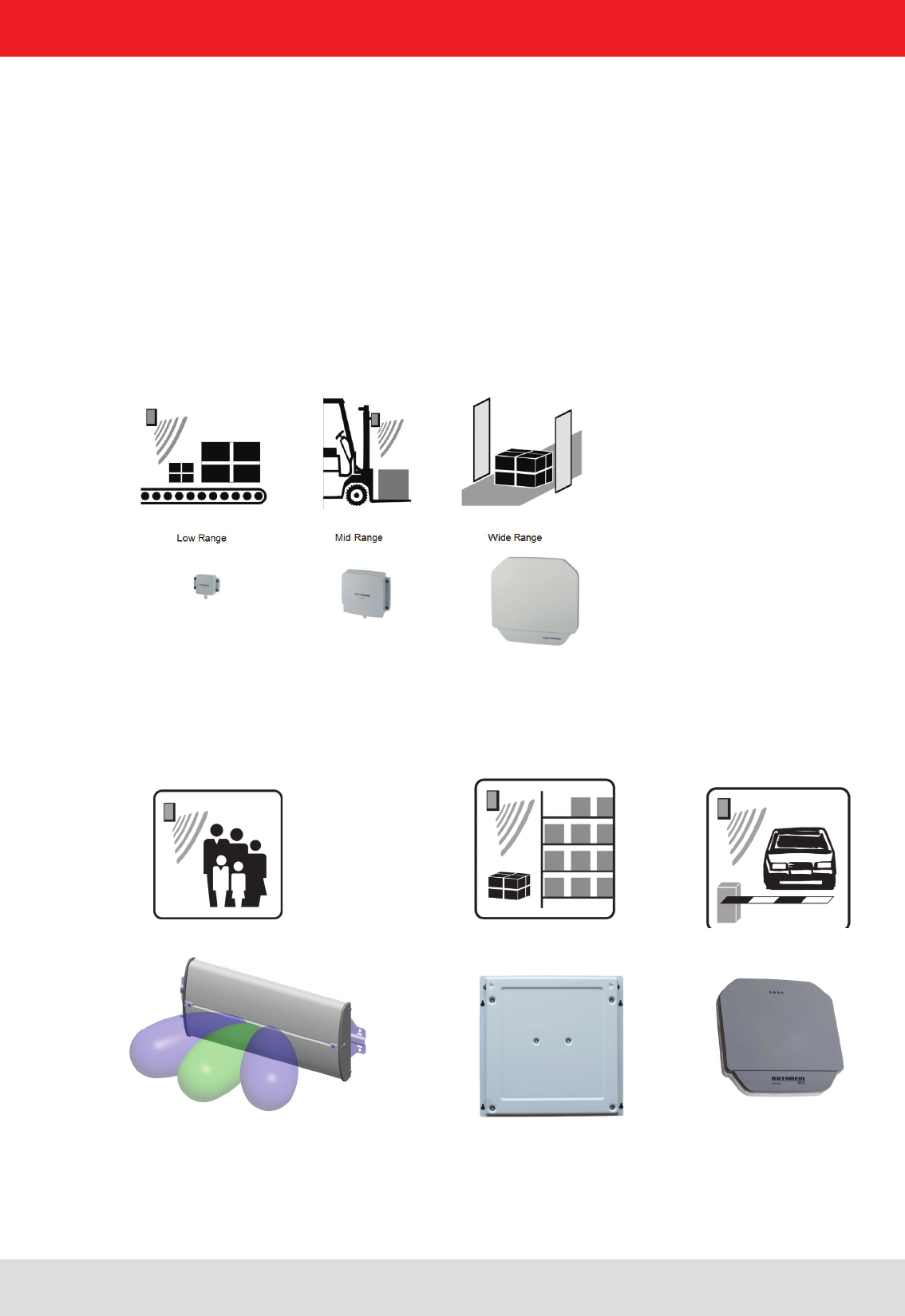
The antennas are divided into three product lines with respect to the reading range: low range, mid range and wide
range antennas.
This allows to up 4 antennas are used simultaneously in any combination with Kathrein RFID reader. This modularity
is only possible with Kathrein RFID readers and antennas.
0 to 10 cm - with Low Range antenna
20 cm to 2 m - with Mid Range antenna
1 m to 10 m - with Wide Range antenna
2.1.1. © KRAI Antennen
Die © KRAI-Antennen werden über © KRAI Reader angesteuert. Dabei können die keweiligen Funktionen
- Kaskadierung
- Beam Switching
- Polarisierung
dynamisch ausgewählt werden.
2.1.1. Standard antennas
Die abgebildeteten Antennen stellen je Beispiele aus der jeweiligen Antennenserie da.
Weitere Informationen nden Sie unter 3. Produktbeschreibung.
CSB antennas SMSH antennas Wide Range antennas
Installation manual antennas 9
Modications, misprints and errors excepted
English
The package content includes the following:
- 1 antenna
- associated technical data sheets
2.2. Scope of supply
In the delivery of antennas is included no cable. These must be ordered separately.
2. Introduction
- Cable sets (without antenna cable)
Order number Type Product type
For use only RRU and ARU Reader:
52010125 CK-RRU RS4
Power supply cable M12/open, length 1.5 m,
RS 422/485 interface cable M12/open, length 1.5 m,
2 x GPIO cable M12/open, length 1.5 m
52010126 CK-RRU ETG
Power supply cable M12/open, length 1.5 m,
Ethernet interface cable M12/RJ 45 socket, length 1.5 m,
2 x GPIO-Kabel M12/offen, length 1.5 m
52010189 CK-M-ARU RS Connecting cable M-ARU RS232, length 1.5 m
52010239 R-CC 10 GPIO GPIO Connecting cable RRU4/ARU4, length 10 m
52010240 R-CC 10 DC Power Connecting cable RRU4/ARU4, length 10 m
For use only M-ARU Reader:
52010189 CK-M-ARU RS Combination cable for power supply
GPIOs and RS232 interface, M12/open, length 1.5 m
52010209 CK-M-ARU PoE Combination cable for power supply and PoE
interface, M12/RJ 45, length 1.5 m
52010238 R-CC 10 ETH Ethernet Connecting cable RRU4/ARU4/M-ARU, length 10 m
52010241 R-CC 10 RS M-ARU Connecting cable RS, length 10 m
2.3. Accessories
The following accessories are available for the reader (if you have questions about the accessories, please contact
our Sales Ofce):
- Antennas: For use with UHF-RFID antennas; we recommend the Kathrein RFID antenna types ULoRa, LoRa,
MiRa, WiRa. These antenna types are available for all frequency ranges.The mentioned types of antennas
are available for all frequency ranges and in protection class IP 65
Order number Type Connector 1 Connector 2 Lenght (cm)
52010174 R-AC 3 TNC-TNCR
TNC TNC Reverse
LL240 ex, 300
52010175 R-AC 6 TNC-TNCR LL240 ex, 600
52010176 R-AC 10 TNC-TNCR LL240 ex,1000
52010177 R-AC 15 TNC-TNCR LL240 ex,1500
52010178 R-AA TNC-N(f-m) TNC (socket) N-(Socket)
52010250 R-AC-15-N-TNCR N (Socket) TNC (Socket) LL400 ex, 1500
52010090 R-AC 3 SMA-TNCR SMA (socket) TNC (socket) RG 58, 300
52010208 R-AC 05 SMA-SMA SMA (socket) SMA (socket) RG 58, 50
- Antenna cable
Installation manual antennas 10
Modications, misprints and errors excepted
English
2. Introduction
Order number Type Product type
52010005 MK-WiRa30 Wall mount/mast mounting set for 30° WiRa antennas
52010128 MK-ARU WiRa70 Wall mount/mast mounting set for RFID antennas and RRU4/
ARU4-readers (to 6.0 kg total weight).
52010261 MK-WM-100-100-
Indoor
Wal mounting set for WiRa 70° antennas and RRU-, ARU-
Reader; Indoor
52010262 MK-WM-100-100-
Indoor
Wall mount/mast mounting set for WiRa 70° antennas and
RRU-, ARU- Reader; Indoor
- Mounting Accessories
- Protective Covers
Order number Type Product type
52010179 R-RPA
115-230V/24V
RRU / ARU 230V power supply with safty plug (Lörar);
24V DC power supply with M12 socket 4-pin, A-coded
52010192 R-ERPA 115-
230V/24V
ERU 230V power supply
24V DC cable plug connector 2.5 mm
Order number Type Product type
52010127
Protective covers
set for the RRU and
ARU reader series
Accessories for RRU4/ARU4 reader with screw caps for
3x antenna input (R-TNC) and 2x digital (M12)
- Readers power supply
Installation manual antennas 11
Modications, misprints and errors excepted
English
3. Product description
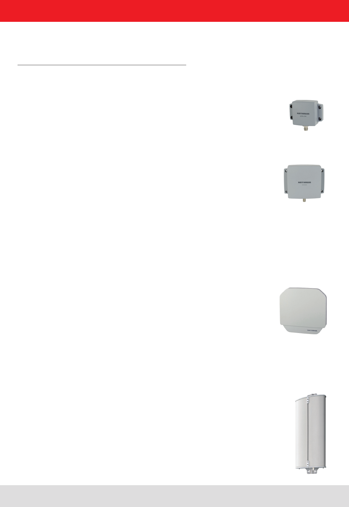
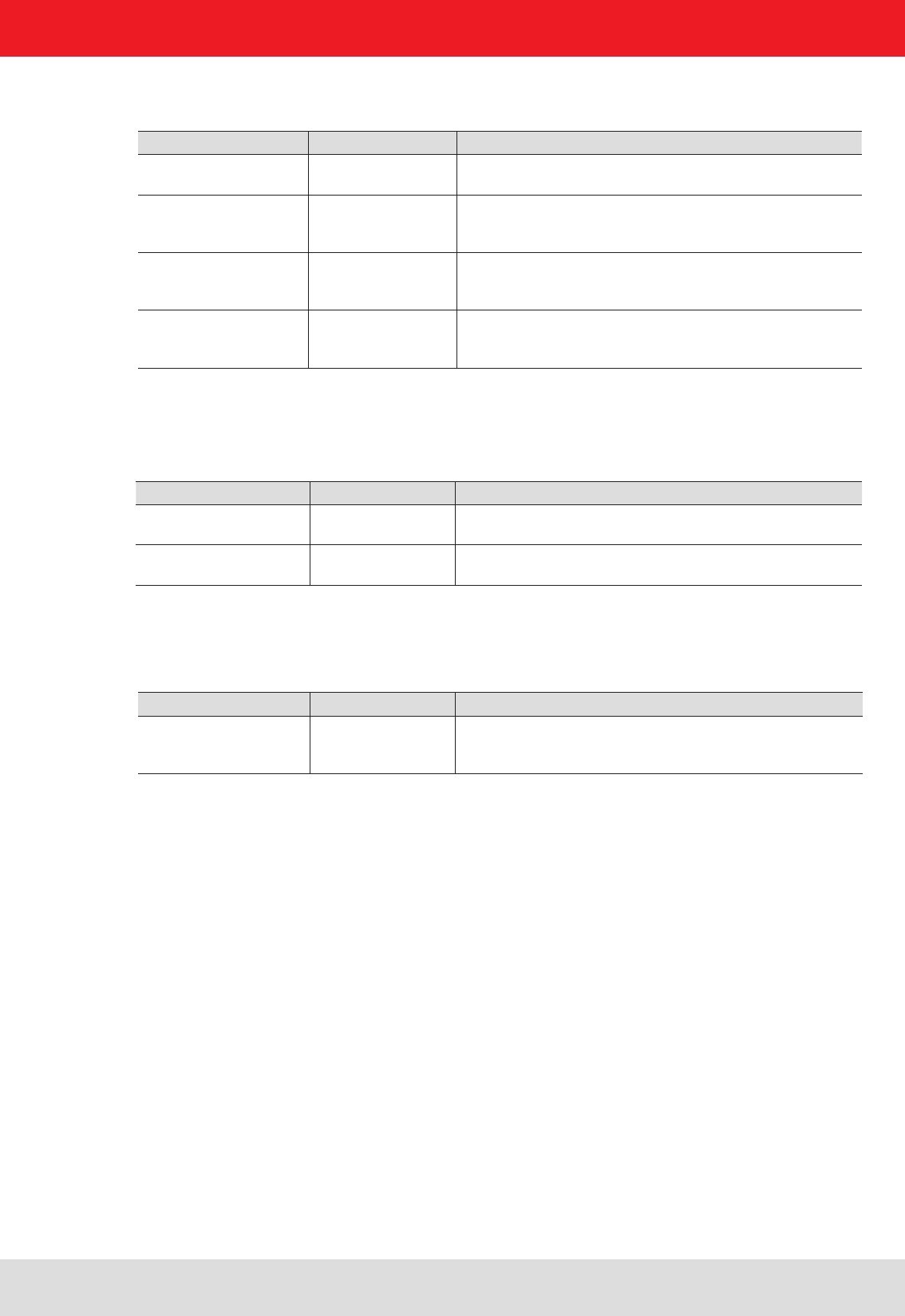
3.1. Low range antennas
The low range antennas are a highlight of the new antenna series. With dimensions of 90 x 63 mm, these antennas
have a high eld concentration in the near-eld, with signicantly reduced antenna gain in the far-eld. With these
properties, the antennas achieve outstanding writing/reading performence at ranges of up to 10 cm with a typical
selectivity of 5 cm. Low range antennas are available in LoRa (Low Range) and ULoRa (Ultra Low Range). The
ULoRa was designed to read dipole-shaped tags (“far-eld tags” at an extremely limited distance.
These antennas can also read loopshaped tags (“near-eld tags”) up to 3 cm. The LoRa was developed for
larger ranges and is particularly suited to near- eld tags.
3.2. Mid range antennas
The MiRa 100° was developed for applications in the area between near eld and far- eld. Particular importance
was placed on creating a compact construction to enable integration into environments with limited space. Read
ranges of over 2 m are still possible even with dimensions of 156 x 126 mm. MiRa also offers increased selectivity at
lower reading distances compared with conventional antennas. This antenna design is therefore also suitable for
use in the so-called transition area with a variety of transponder types
For short range to offer the S-MiRa antenna that is optimized with the same basic Paramenter for angle and trans-
mission level as our standard mid range antenna, small reading range to 1.0 m.
Figure 1: Low range antenna Figure 2: Ultra-Low range antenna
Figure 4: Mid range antenna
Figure 3: Short-Mid range antenna
The SMSH 30-30-KRAI slave antenna was developed for applications in the eld of point of sale, smart shelf ap-
plications and Kanban solutions. The antenna is characterized by an extremely homogeneous read zone, which is
emitted by the high front to back ratio. Therefore it is suitable for static detection of multiple transponders. Due to
their extremely thin design, the antenna module can be integrated into different applications universal.
The antenna is equipped with an intelligent bypass circuit that allows for cascading up to 8 SMSH modules per
reader port. The control is done by a suitable © KRAI Kathrein RFID reader, the © KRAI control signals are trans-
mitted via the standard antenna cable
3.3. Smart Shelf antennas
Figure 5: SMSH with protectiv cover / SMSH wi-
thout protectiv cover
Installation manual antennas 12
Modications, misprints and errors excepted
English
3. Product description
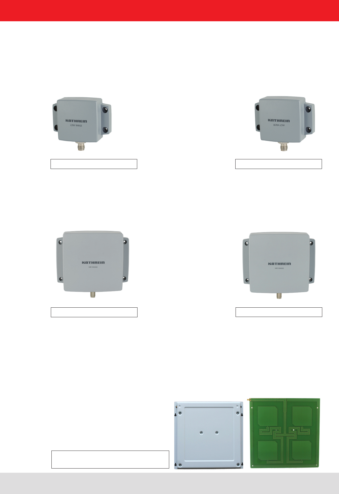
3.4. Wide Range antennas
For the standard wide range applications with read ranges up above 10 m Kathrein offers wide range antenna
types, which are characterized by a beam width of 70° (WiRa 70), 40° (WiRa 40) and 30° (WiRa 30) and a cir-
cular or linear polarization
antenna typ Order number Öffnungswinkel Polarisation Frequenzbereich
WiRa 30 ETSI 52010086 30° circular 865 – 868 MHz
WiRa 30 FCC 52010087 30° circular 902 - 928 MHz
WiRa 30 - linear ETSI 52010248 30° linear 865 – 868 MHz
WiRa 30 - linear FCC 52010249 30° linear 902 - 928 MHz
WiRa 40 - linear ETSI 52010251 40° linear 865 – 868 MHz
WiRa 40 - linear FCC 52010252 40° linear 902 - 928 MHz
WiRa 70 ETSI 52010078 70° circular 865 – 868 MHz
WiRa 70 FCC 52010079 70° circular 902 - 928 MHz
For standard UHF applications a circular polarization is used, when the orientation of the transponders is not
known, or may occur a randomly. This circular polarization was signicantly improved in comparison to the an-
tennas available on the market. For the so-called axial ratio, which is used as a characteristic value for circular
polarization, the two new models achieve typical values of 1 dB. If speci ed at all, the usual value on the market
lies at around 3 dB. The improved circularity of the Kathrein wide range antennas leads to a signicantly reduced
inuence of the read results caused by the position or orientation of the transponder.
Linearly polarized antennas are used for UHF applications, if the orientation of the transponder is xed and well
dened. In this case, the lower polarization loss of linear antennas will lead to bigger read range.
Great importance was also placed on the front-to-back ratio of the antennas to reduce
the inuence of the adjacent (installation) environment on the antenna properties.
All antennas have an extremely high protection class which guarantees problem-free use in any environment.
The use of high-quality materials for a long service life and high levels of reliability contribute to the optimal perfor-
mance provided by the antennas under even the most challenging of conditions.
Figure 6: Wide Range 70° antenna Figure 8:
Wide Range 30° antenna
Figure 7: Wide Range 40° antenna
Installation manual antennas 13
Modications, misprints and errors excepted
English
3. Product description
3.5. © KRAI Antennen
With © KRAI (Kathrein RFID Antenna Interface) the electrical feature of a © KRAI RFID Antenna can be controlled
by a © KRAI Reader via the existing standard Coaxial cable. The conguration of the reader will be installed with
the Kathrein ReaderStart SW V2.xx.
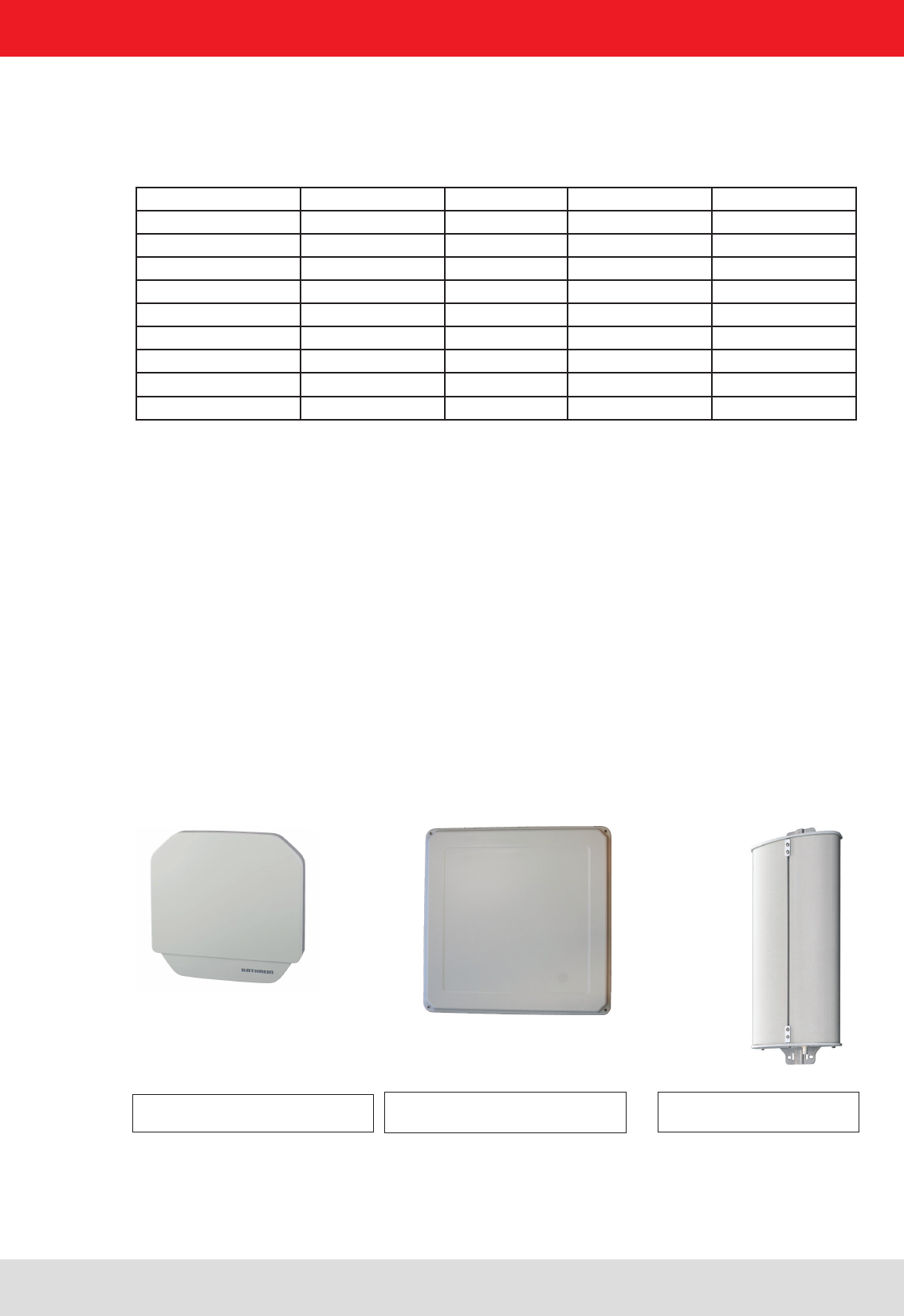
3.5.1. © KRAI SMSH (Smart Shelf-) antenna
The SMSH 30-30-KRAI slave antenna was developed for applications in the eld of point of sale, smart shelf ap-
plications and Kanban solutions. The antenna is characterized by an extremely homogeneous read zone, which is
emitted by the high front to back ratio. Therefore it is suitable for static detection of multiple transponders. Due to
their extremely thin design, the antenna module can be integrated into different applications universal. The antenna
is equipped with an intelligent bypass circuit that allows for cascading up to 8 SMSH modules per reader port.
The control is done by a suitable © KRAI Kathrein RFID reader, the © KRAI control signals are transmitted via the
standard antenna cable.
Figure 9: SMSH antenna
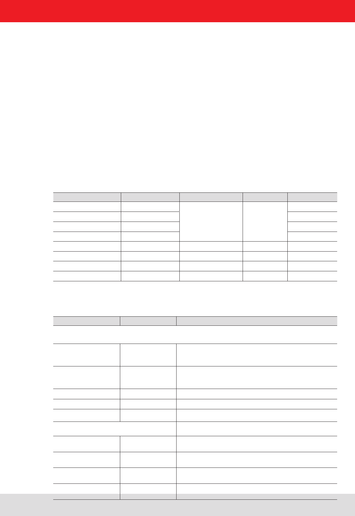
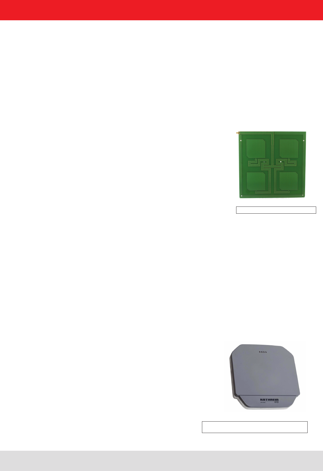
3.5.2. © KRAI PLS (Polarisation Switching-) antenna
With the © KRAI PLS-Antenna, build as a WiRa 70° Antenna, the polarization can be switched static or dynamically.
The following settings are possible in any combination:
- Circular LHCP
- Circular RHCP
- Linear horizontal
- Linear vertical
For Wide Range application the best polarization can be selected. A exible adjustment of the antenna on site is
possible.
In addition the read rate can be increased via the switching circular LHCP / RHCP by up to 30%.
For direct access programming 4 LEDs are free for visualization.
Figure 10: Wide Range © KRAI 70° antenna
Installation manual antennas 14
Modications, misprints and errors excepted
English
3. Product description
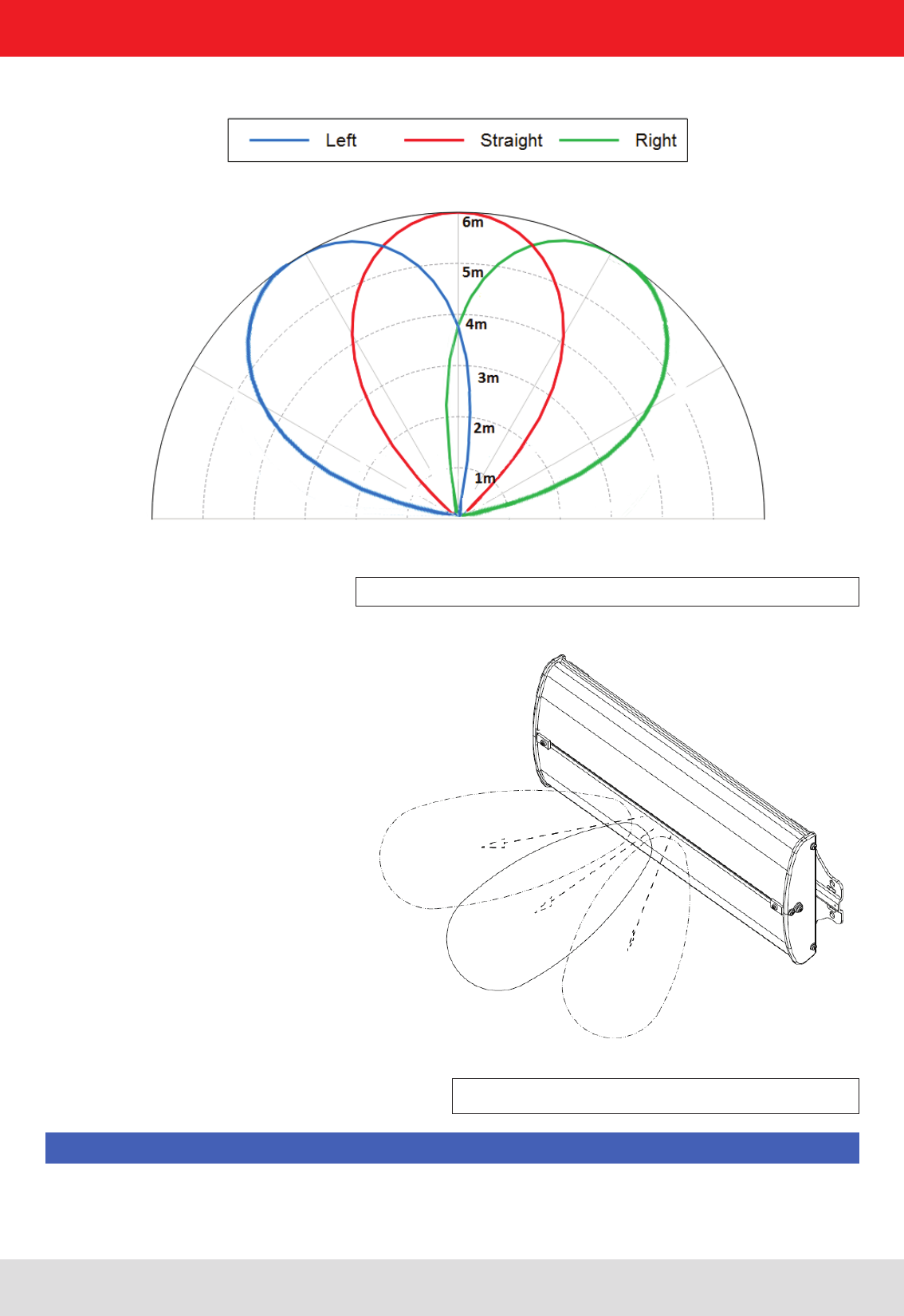
3.5.3. © KRAI CSB (Circular Switch Beam-) antenna
With the ©KRAI CSB-Antenna, build as a WiRa 30° antenna, the antenna beam can be switched static or dynami-
cally. The following settings are possible in any combination:
- Antenna beam initial position (radiation 90°of the Antenna)
- Antenna beam switched 35° to the left
- Antenna beam switched 35° to the right
The orientation of switching is in the longitudinal direction of the antenna. On the connector side of the antenna the
position “RIGHT” is dened.
These CSB antennas are used to detect the movement of the transponder. This information will be transferred in
combination with the collected transponder is. With 5 antenna sweeps per second, two or more reads are used to
determine the direction of movement.
Figure 11: Wide Range © KRAI CSB 30° antenna
Please note that the Beam „R“ is assigned (right) getting the connection side.
Note
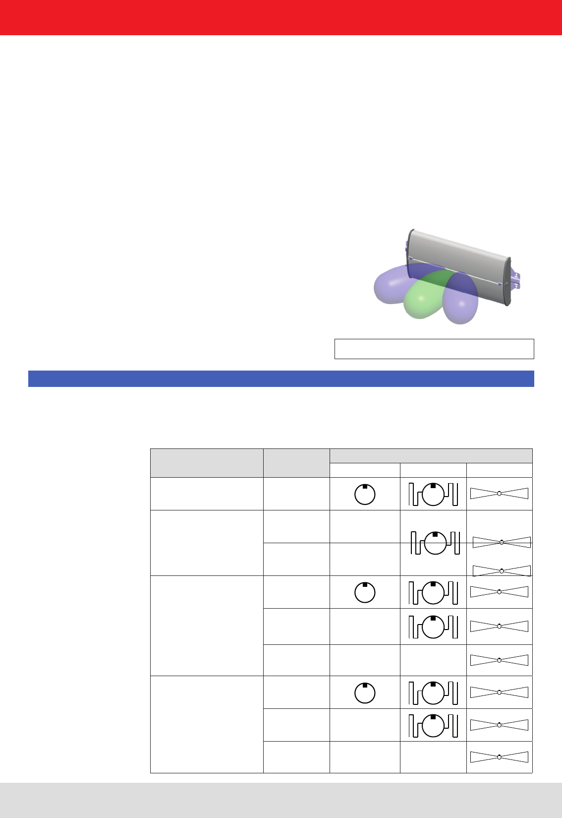
Antenna type Read range Tag type
Loop-shaped Hybrid Dipole-form
LoRa
ULoRa 0-10 cm
SMiRa,
SMSH
0-10 cm
10-100cm
MiRa
0-30 cm
30-100 cm
> 100 cm
WiRa 70°,
WiRa 40,
WiRa 30° linear,
WiRa-30-CSB-KRAI
0-30 cm
30-200 cm
> 200 cm
3.6. Antenna type according to read range and transponder shape
Installation manual antennas 15
Modications, misprints and errors excepted
English
3. Product description
The correct combination of reader antenna and transponder is essential for every RFID application. The correct
selection ensures a high read rate and reliable operation of the system.
The LoRa and ULoRa antennas can read loop-shaped, hybrid-form and dipole-form transponders up to 10 cm and
offer a very well de ned read range.
The Smart shelf and SMIRA read the hybrid transponders at distances up to 10cm and the dipole type transponders
at distances up to 100cm.
MiRa can read loop-shaped transponders up to 30 cm, hybrid-form transponders up to 100 cm and dipole-form
transponders up to several metres.
The WiRa antennas ans WiRa-30-CSB-KRAI antennas are designed for typical dipole-form transponders with read
ranges of up to 10 m, but they can also read loop-shaped and hybrid-form transponders at a short distance.
The typical read ranges of the antennas described can be seen in the following gure. If WiRa 30°
and WiRa 70° are operated with the same ERP, the maximum ranges of the two antennas are equal,
although the WiRa 30° has a higher selectivity.
Installation manual antennas 16
Modications, misprints and errors excepted
English
Note
To achieve the best reading and writing results, we recommend operating the Kathrein UHF RFID reader an-
tennas exclusively with UHF readers from Kathrein.
As a further option, it is possible to integrate the modular Kathrein RFID UHF reader latform in the WIRA antennas
to also provide a powerful single read point for certain applications. As a result of the consistent continuation of the
platform strategy for antenna and reader, all product and interface variants already introduced are available in nu-
merous combinations. Cost-ef cient adaptation to varying customer requirements is therefore possible as a result.
For all variants protection class IP 67 and an operating temperature range from -20 to +55 °C apply. A TNC socket
is used as the antenna interface on all types.
3. Product description
For maximum range there must not be any interfering objects between the antenna and the tag to be read.
Note
3.7. Maximum range

Installation manual antennas 17
Modications, misprints and errors excepted
English
4.1. Ultra-Low range and Low range antennas
Type U-LoRa (ETSI/FCC) LoRa (ETSI) LoRa (FCC)
Order number 52010092 52010084 52010085
Frequency range MHz 865-928 865-868 902-928
Antenna gain dBi -30 -15 -15
EIFF*)dB 15 20 20
VSWR <1.2:1 <1.3:1 <1.8:1
Impedance Ω50 50 50
Range of near eld tags **)cm 3 7 7
Selectity of near eld tags **)cm 3 5 5
Range of far eld tags **)cm 8 - -
Selectity of far eld tags **)cm 10 - -
Max. input power ***)W 1 0.5 0.5
Connection TNC socket TNC socket TNC socket
Protection class IP 67 IP 67 IP 67
Weight g 110 110 110
Dimensions (W x H x D) mm 79,5 x 90 x 31 79,5 x 90 x 31 79,5 x 90 x 31
Packing dimensions (approx.) mm 165 x 250 x 50 165 x 250 x 50 165 x 250 x 50
Material Tough, weather-resistant polymer blend; Colour: RAL7045
Installation Four through-holes Ø 4.2 mm for M4 screws
Operating temperature range
°C -20 to +55
Storage temperature range °C -40 to +85
*) The Effective Isotropic Field Factor (EIFF) shows the eld isolation from far eld to near eld standardised to an isotropic
radiator. The values were determined with 3 cm spacing
**) dependant upon transmission power and tag type
***) compliant to FCC
4. Technical data
Installation manual antennas 18
Modications, misprints and errors excepted
English
4. Technical data
Loop-shaped
(near eld tags)
Hybrid
Dipole-form
(far eld tags)
Tag types Ultra Low range antenna Low range antenna
LoRa antennas are only suitable for loop-shaped tags.
There is no dened reading zone with hybrid tags and dipole-form tags.
Figure 12: Read ranges of LoRa and U-LoRa by tag antenna

Installation manual antennas 19
Modications, misprints and errors excepted
English
4.2. Short-Mid range antenna
Type S-MiRa (ETSI/FCC)
Order number 52010172
Frequency range MHz 865-928
Polarization circular
Antenna gain dBic -12 @ 866 MHz
-10 @ 915 MHz
Axial ratio dB typ. 2
VSWR < 1.4:1
Impedance Ω50
Front-to-back ratio dB > 8
(depending upon installation situation)
Max. input power
(FCC15.247 / ETSI EN 302 208)
W 1.0
Far eld half power beam width ° 100° half power beam width
Connection TNC socket
Protection class IP 67
Weight g 320
Dimensions (W x H x D) mm 154 x 126 x 36
Packing dimensions (approx.) mm 230 x 160 x 81
Material Tough, weather-resistant polymer blend; colour: RAL7045
Installation Four through-holes Ø 4.2 mm for M4 screws
Operating temperature range
° C -20 to +55
Storage temperature range °C -40 to +85
4. Technical data
Installation manual antennas 20
Modications, misprints and errors excepted
English
4. Technical data
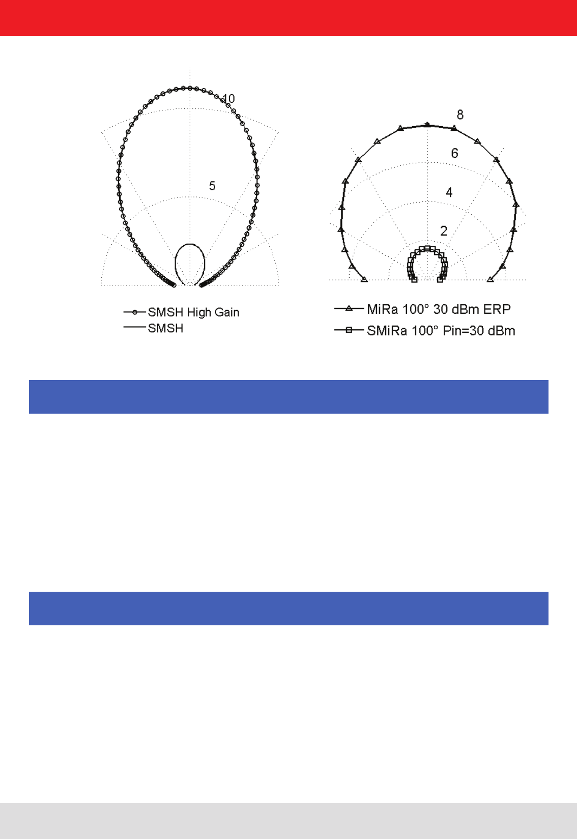
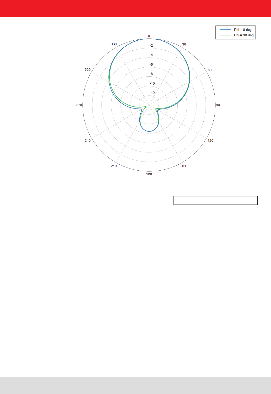
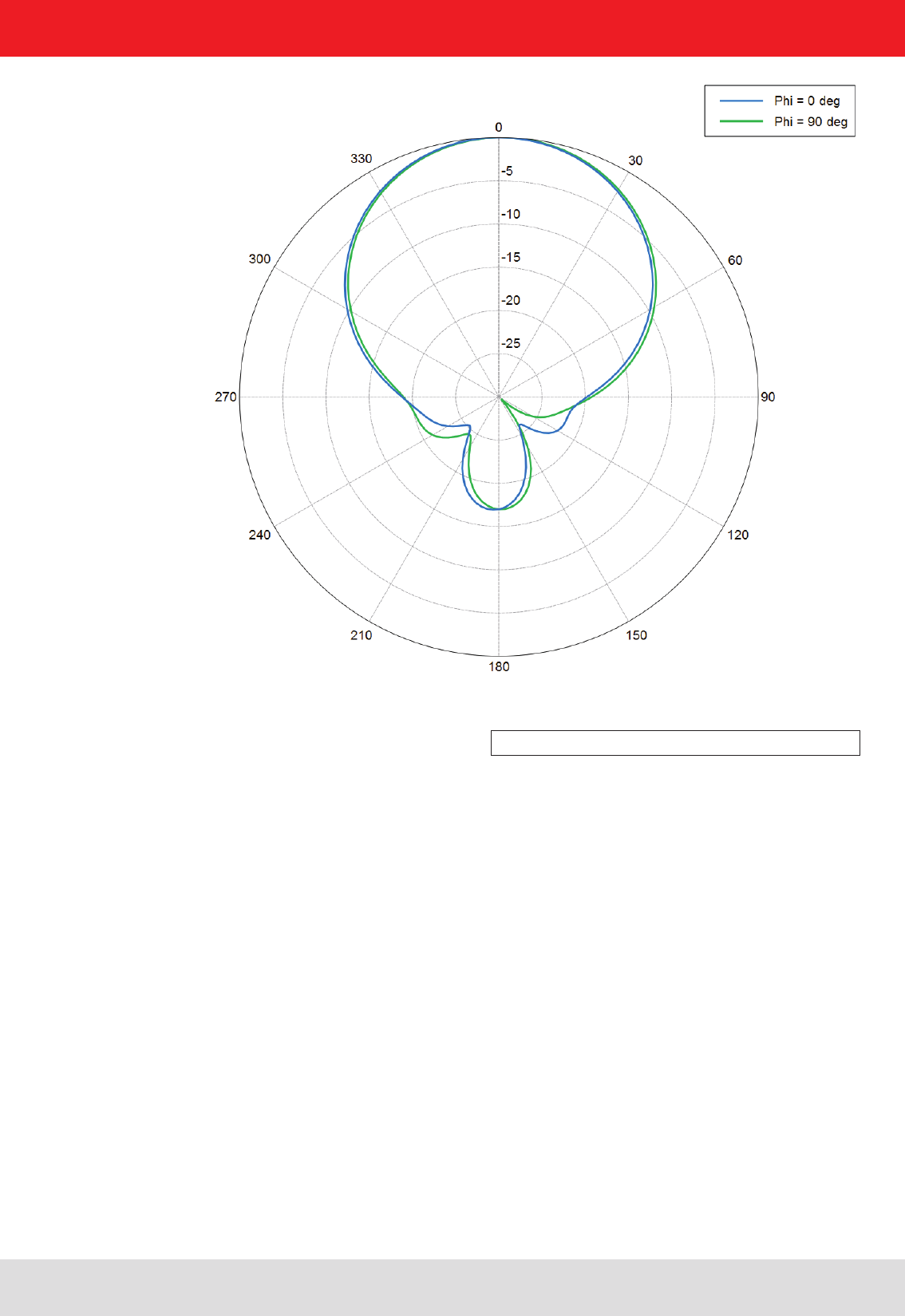
The antenna directivity shows the propagation characteristics of the EM eld of the antenna.
The half power beam width and the front to your ratio can be read from it.
Figure 13: Antenna directivity S-MiRa

Installation manual antennas 21
Modications, misprints and errors excepted
English
4. Technical data
Type
MiRa (ETSI) MiRa (FCC)
Order number 52010082 52010083
Frequency range MHz 865-868 902-928 MHz
Polarization circular circular
Antenna gain dBic 2.5 2.5
Axial ratio dB typ. 1.5 typ. 2.5
VSWR < 1.3:1 < 1.5:1
Impedance Ω50
Front-to-back ratio - circular dB > 10
(depending upon installation
situation)
> 10
(depending upon installation
situation)
Max. radiated power
(ETSI EN 302 208)
W 1.0 ERP -
Max. input power
(FCC 15.247)
W - 1.0
Far eld half power beam width ° 100° half power beam width 100° half power beam width
Connection TNC socket
Protection class IP 67
Weight g 320
Dimensions (W x H x D) mm 156 x 143.8 x 36
Packing dimensions (approx.) mm 230 x 160 x 81
Material Tough, weather-resistant polymer blend; colour: RAL7045
Installation Four through-holes Ø 4.2 mm for M4 screws
Operating temperature rang
e °C -20 to +55
Storage temperature range °C -40 to +85
4.3. Mid range antennas
Installation manual antennas 22
Modications, misprints and errors excepted
English
4. Technical data
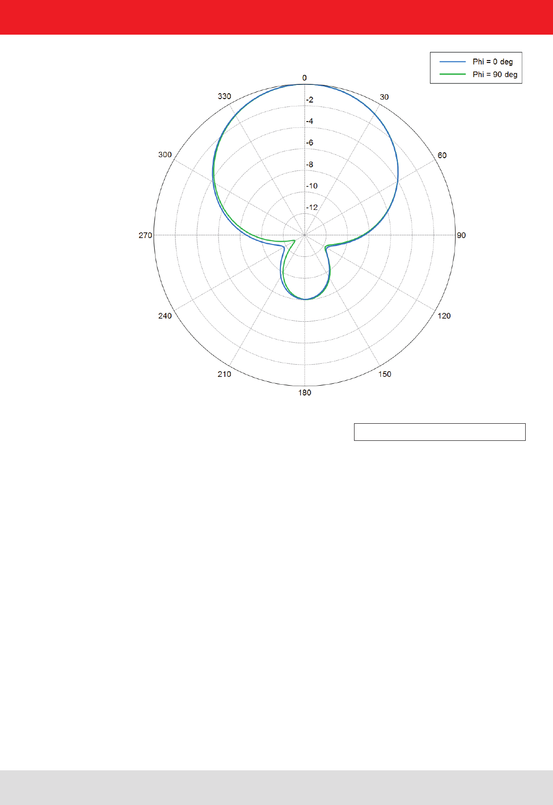
The antenna directivity shows the propagation characteristics of the EM eld of the antenna.
The half power beam width and the front to your ratio can be read from it.
Figure 14: Antenna diagram MiRa
Installation manual antennas 23
Modications, misprints and errors excepted
English
Type
SMSH-30-30-antenna
modul
SMSH-HighGain-
30-30-EU-antenna modul
Order number 52010219
52010260
Frequency range MHz 865-928 865-870
Polarization circular circular
Antenna gain dBic typ. -7 typ. 5
Axial ratio dB typ. 1.5 typ. 2
VSWR typ. 1.25:1
Impedance Ω50
Front-to-back ratio - circular dB >20
Max. radiated power
(ETSI EN 302 208)
W +33 +33
Max. input power
(FCC 15.247)
W +30
(at Antenna port)
Far eld half power beam width ° 60/60
Connection input: SMA-socket
output: SMA-socket
Protection class IP 65
Weight g 0.5
Dimensions (W x H x D) mm 310 x 300 x 8.6
Packing dimensions (approx.) mm 330 x 310 x 25
Material berglass-epoxy resin; copper, gold
Installation 10 through-holes Ø 4,5 mm for M4 screws
Operating temperature range
°C -20 to +55
Storage temperature range °C -40 to +85
4.4. SMSH antennas
4. Technical data

Installation manual antennas 24
Modications, misprints and errors excepted
English
Type
SMSH-30-30-KRAI an-
tenna
SMSH-HighGain-
30-30-KRAI-EU-antenna
modul
Order number 52010258
52010259
Frequency range MHz 865-928 865-870
Polarization circular circular
Antenna gain dBic typ. -7 typ. 5
Axial ratio dB typ. 1.5 typ. 2
VSWR typ. 1.25:1 typ. 1.25:1
Impedance Ω50 50
Front-to-back ratio - circular dB >20 >20
Max. radiated power
(ETSI EN 302 208)
W +33
(ETSI EN 302 208)
+33
(ETSI EN 302 208)
Max. input power
(FCC 15.247)
W +30
(an Antennen-Buchse)
Far eld half power beam width ° 60/60
Connection input: SMA socket
output: SMA socket
Protection class Indoor
Weight g ~0.5
Dimensions (W x H x D) mm 330 x 340 x 20
Packing dimensions (approx.) mm 345 x 350 x 35
Material berglass-epoxy resin; copper, gold
Installation 10 through-holes Ø 4,5 mm for M4 screws
Operating temperature range
°C -20 to +55
Storage temperature range °C -40 to +85
4.5. SMSH © KRAI antennas
4. Technical data
The antenna can be operated only in conjunction with a © KRAI Reader. When commissioning the antenna is circularl RHC
polarized.
Note
Installation manual antennas 25
Modications, misprints and errors excepted
English
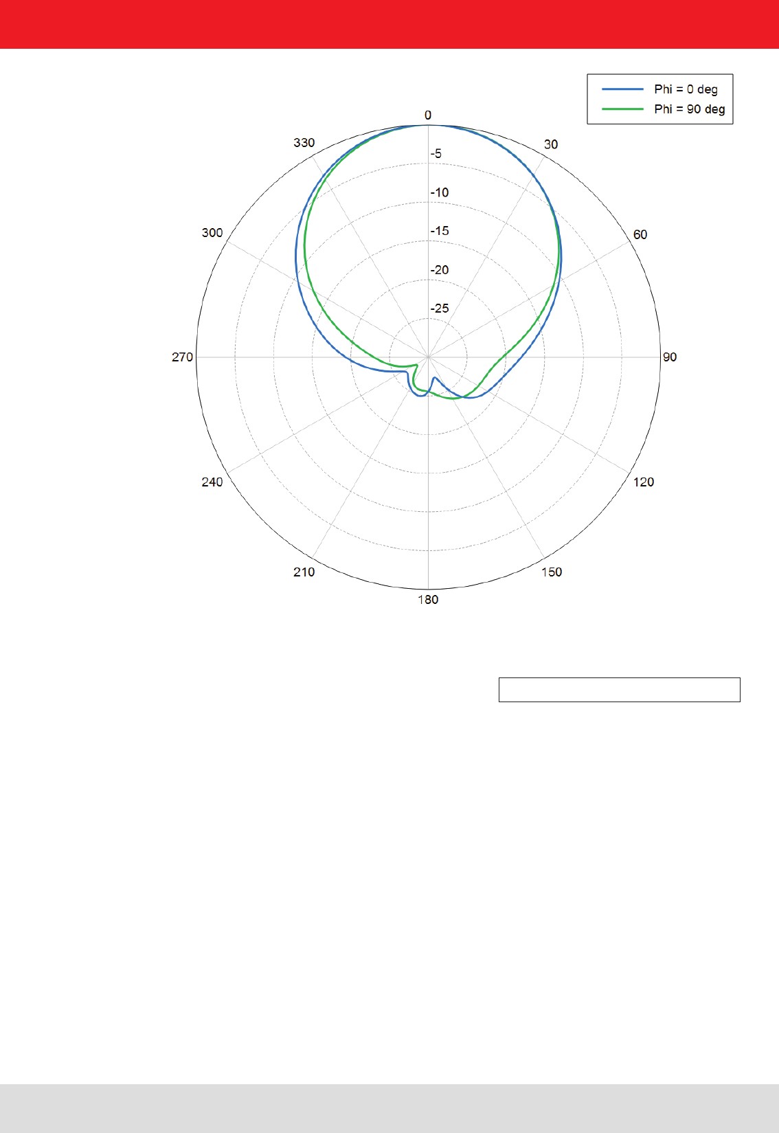
4. Technical data
Figure 15: Antenna diagram SMSH

Installation manual antennas 26
Modications, misprints and errors excepted
English
4. Technical data
Type WiRa 70° (ETSI) WiRa 70° (FCC)
Order number 52010078 52010079
Frequency range MHz 865-868 902-928
Polarization right-Hand circular (RHC)
Antenna gain dBic 8.5 @ 866 MHz 8.3 @ 915 MHz
Axial ratio dB typ. 1
VSWR < 1.2:1
Impedance Ω50
Front-to-back ratio dB > 18
Max. radiated power W 2.0 ERP
(ETSI EN 302 208)
4.0 EIRP
(FCC 15.247)
Far eld half-power beam width ° 69°/69°
Connection TNC-socket
Protection class IP 65
Weight kg ~1.7
Dimensions (W x H x D) mm 271 x 271 x 45
Packing dimensions (approx.) mm
300 x 300 x 150
Material Tough, weather-resistant polymer blend
Installation Four M5 drill holes 100 x 100 mm
Operating temperature range °C
-20 to +55
Storage temperature range
°C
-40 to +85
4.6. Wide range 70° antennas

Installation manual antennas 27
Modications, misprints and errors excepted
English
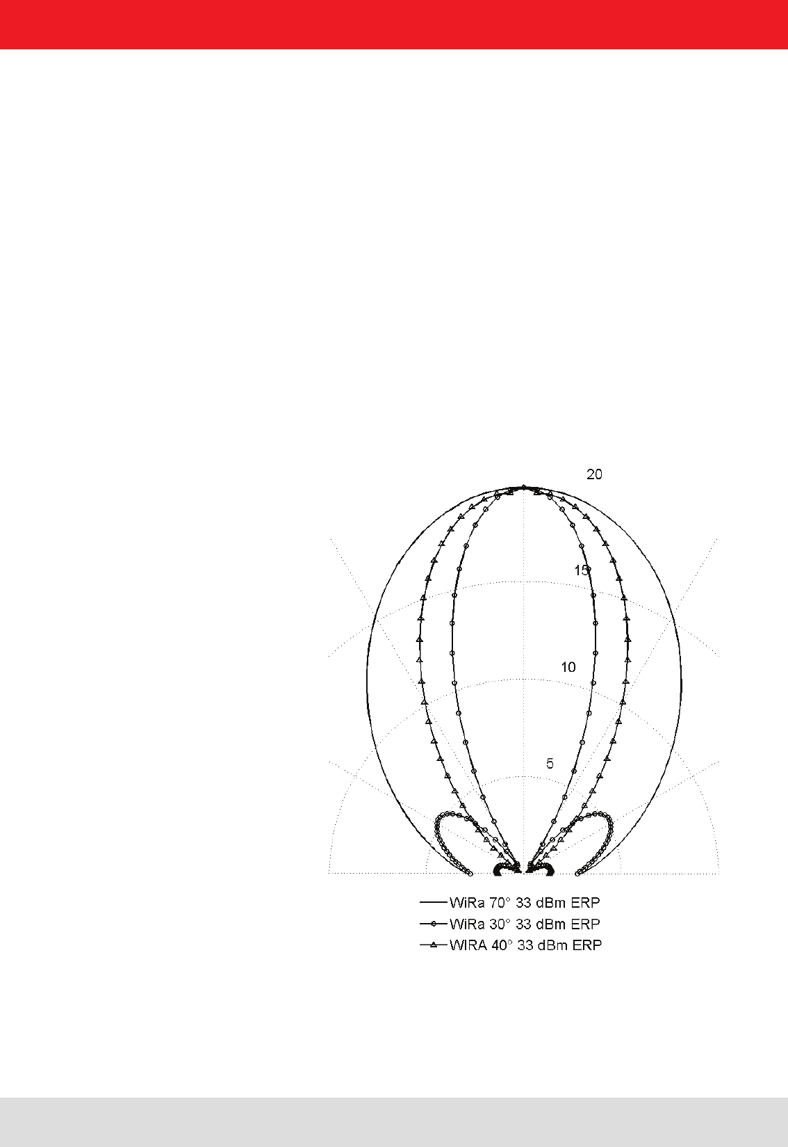
The antenna points to the propagation characteristics of the EM eld of the antenna.
It would therefore appear the opening angle and the front-back ratio.
4. Technical data
Figure 16: Antenna diagram WiRa 70° ETSI/FCC

Installation manual antennas 28
Modications, misprints and errors excepted
English
4. Technical data
Type WiRa-70°-KRAI (ETSI) WiRa-70°-KRAI (FCC)
Order number 52010193 52010194
Frequency range MHz 865-868 902-928
Polarization circular LHCP / RHPC *
- Antenna gain
dBiC typ. 6,5
- Axial ratio
dB typ. 2
Polarization linear Horizintal / Vertical
- gain dBic typ. 7.5
- VSWR < 1.2:1
Impedance Ω50
Front-to-back ratio dB > 18
Max. radiated power 2.0 ERP
(ETSI EN 302 208)
4.0 EIRP
(FCC 15.247)
Far eld half-power beam width ° 69°/69°
Connection TNC-socket
Protection class IP 65
Weight kg ~1.7
Dimensions (W x H x D) mm 271 x 271 x 45
Packing dimensions (approx.) mm
300 x 300 x 150
Material
Antenna cover Tough, weather-resistant polymer blend
Colour: RAL7045
Chassis Aluminium
Seals Thermoplastic elastomer
Installation Four M5 drill holes 100 x 100 mm
Operating temperature range °C
-20 to +55
Storage temperature range
°C -40 to +55
4.7. Wide range © KRAI 70° antennas
* (Circular LHCP / Circular RHCP / Linear horizontal / Linear vertical)
Note
The antenna can be operated only in conjunction with a © KRAI Reader. When commissioning the antenna is circularl RHC
polarized.
Installation manual antennas 29
Modications, misprints and errors excepted
English
4. Technical data
Figure 17: Antenna diagram WiRa-70°-KRAI ETSI/FCC

Installation manual antennas 30
Modications, misprints and errors excepted
English
4. Technical data
4.7. Wide Range 40° Antenne
Type WiRa 40° linear
(ETSI)
WiRa 40° linear
(FCC)
Order number 52010251 52010252
Frequency range MHz 865-870 902-928
Polarization linear
Antenna gain dBic typ. 12 typ. 13
VSWR < 1.3:1 < 1.5:1
Impedance Ω50
Front-to-back ratio dB >18 >25
Max. radiated power W +33 ERP
(ETSI EN 302 208)
+36 EIRP
(FCC 15.247)
max. input power W +30 (at antenna port)
Far eld half-power beam width ° 42/42 40/40
Connection N female
Protection class IP 65
Weight kg ~ 3
Dimensions (W x H x D) mm
456 x 456 x 25 (45.5)
Packing dimensions (approx.) mm
470 x 495 x 65
Material
Antenna cover
Thermoplastic radome, UV resistance,
gray
Chassis
Stainless steel
Installation
The mounting kit (Order-No. 52010005) is available
as accessory
Operating temperature range °C -20 to +55
Storage temperature range
°C
-40 to +85
Installation manual antennas 31
Modications, misprints and errors excepted
English
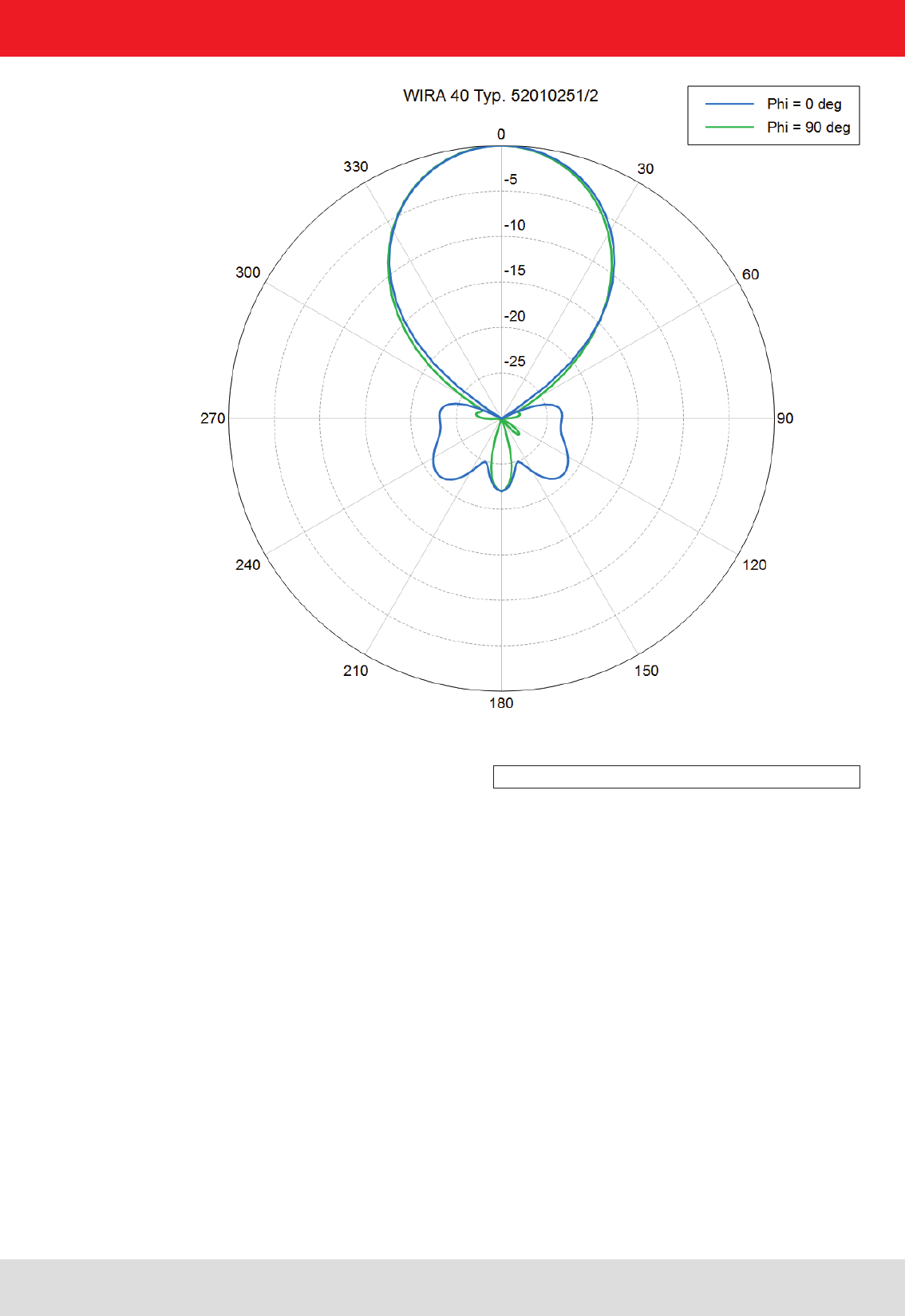
4. Technical data
Figure 18: Antenna diagram WiRa-40-linear ETSI/FCC

Installation manual antennas 32
Modications, misprints and errors excepted
English
4. Technical data
4.7. Wide Range 30° linear Antenne
Type WiRa 30° linear (ETSI) WiRa 30° linear (FCC)
Order number 52010248 52010249
Frequency range MHz 860-870 902-928
Polarisation
linear
Antenna gain dBic typ. 11 typ. 11.5
Impedance Ω50
VSWR < 1.3:1 < 1.5:1
Front-to-back ratio dB > 18 > 20
Max. radiated power
(ETSI EN 302 208)
W +33 ERP
(ETSI EN 302 208)
+30 (at antenna port)
(FCC 15.247)
Far eld half-power beam width ° 30 vertical
70 horizontal
Connection N female
Protection class IP 65
Weight kg 3.7
Dimensions (W x H x D) mm 557 x 262 x 59
Packing dimensions (approx.) mm
762 x 356 x 203
Material
Antenna cover
Fibreglass radome, UV resistance, gray
Chassis
Stainless steel
Patch plate
Brass tin-plated
Antenna support
Aluminum
Seals
Thermoplastic elastomer
Installation
The mounting kit (Order-No. 52010005) is available
as accessory
Operating temperature range °C -20 to +55
Storage temperature range
°C -40 to +85

Installation manual antennas 33
Modications, misprints and errors excepted
English
4. Technical data
Figure 19: antenna diagram WiRa-40-linear ETSI/FCC

Installation manual antennas 34
Modications, misprints and errors excepted
English
Type WiRa 30° (ETSI) WiRa 30° (FCC)
Order number 52010086 52010087
Frequency range MHz 865-868 902-928
Antenna gain dBic typ. 11 typ. 10,5
Impedance Ω50
VSWR < 1,2:1
Axial ratio dB < 2
Polarization right-handed circular (RHC)
Front-to-back ratio dB > 20
Max. radiated power
(ETSI EN 302 208)
W 2,0 ERP
(ETSI EN 302 208)
-
Max. radiated power
(FCC 15.247)
W - 1 W (30 dBm)
conducted
Far eld half-power beam width ° 30°/69°
Connection N socket
Protection class IP 65
Weight kg ~3,7
Dimensions (W x H x D) mm 557 x 262 x 59
Packing dimensions (approx.) mm
762 x 356 x 203
Material Polymer Blend, Aluminium
Antenna cover
Fibreglass radome, UV resistance, gray
Chassis
Thermoplastic elastomer
Patch plate
Brass tin-plated
Antenna support
Aluminum
Seals
Thermoplastic elastomer
Installation The mounting kit 52010005 is available
Operating temperature range °C -20 to +55
Storage temperature range
°C
-40 to +85
4.9. Wide Range 30° antennas
4. Technical data
Installation manual antennas 35
Modications, misprints and errors excepted
English
4. Technical data
The antenna points to the propagation characteristics of the EM eld of the antenna.
It would therefore appear the opening angle and the front-back ratio.
Figure 20: Antenna diagram WiRa 30° ETSI/FCC

Installation manual antennas 36
Modications, misprints and errors excepted
English
Type WiRa-30-CSB-KRAI (ETSI)
Order number 52010227
Frequency range MHz 865-870
Polarization circular
Antenna gain dBic 6
Impedance Ω50
VSWR <1.3:1
Axial ratio dB typ. 2
Front-to-back ratio dB >17
Max. radiated power
(ETSI EN 302 208)
W 2 ERP
Max. radiated power
(FCC 15.247)
W +30
Far eld half-power beam width ° 35 vertical
80 horizontal
Connection N socket
Protection class IP 65
Weight kg ~ 3,7
Dimensions (W x H x D) mm 557 x 262 x 59
Packing dimensions (approx.) mm
762 x 356 x 203
Material
Antenna cover
Fibreglass radome, UV resistance, gray
Chassis
Stainless steel
Patch plate
Brass tin-plated
Antenna support
Aluminum
Seals
Thermoplastic elastomer
Installation The mounting kit is available
Operating temperature range °C -20 to +55
Storage temperature range
°C -40 to +85
4. Technical data
4.10. Wide Range © KRAI CSB 30° antennas
Installation manual antennas 37
Modications, misprints and errors excepted
English
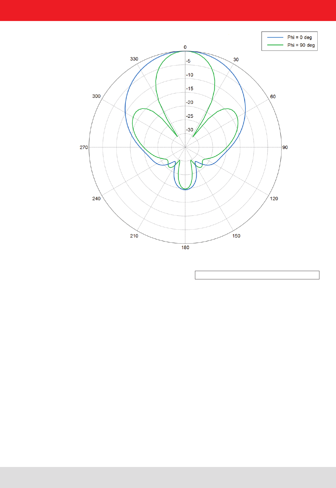
4. Technical data
Figure 21: Read range vertical cut WiRa-30-KRAI- ETSI antenna
Figure 22: Directions of the WiRa-30-CSB-KRAI-ETSI antenna
Please note that the Beam „R“ is assigned (right) getting the connection side.
Hinweis
Installation manual antennas 38
Modications, misprints and errors excepted
English
5. Installation
The MiRa and WiRa antennas are relatively insensitive to the type of attachment and the materials surrounding
the antennas. Nevertheless few conductive objects in the vicinity of the antenna should be presented. In addition,
other objects, such as containers with liquids in the vicinity of the antenna affect their functionality. In such cases,
a reassessment of the antenna in the particular installation conditions is necessary. The LoRa antennas are very
robust and suitable for installation in metallic environment.
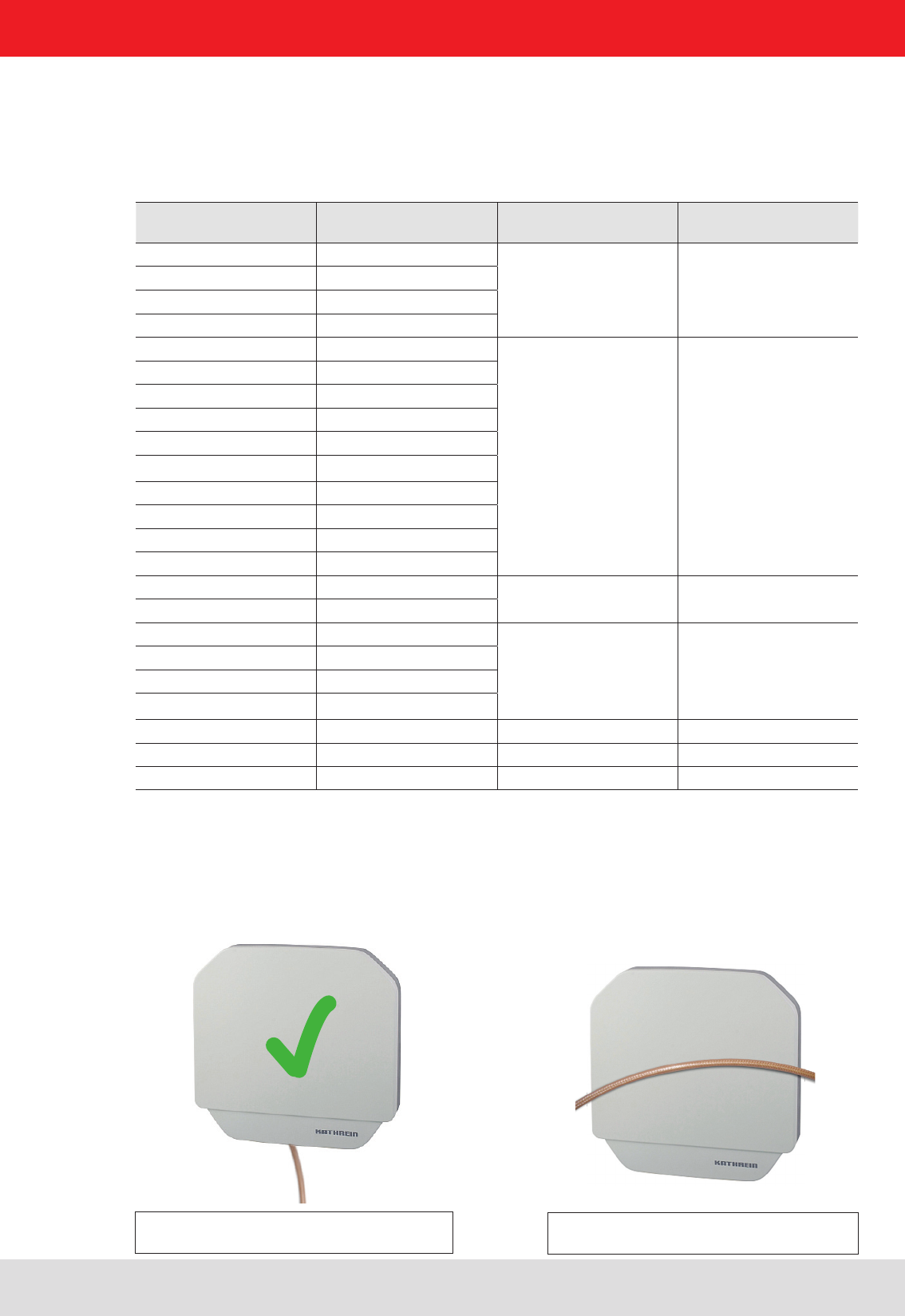
• The cable should be laid vertical (see Figure 13) away from the antenna and should be laid direct. The cable
length is to be selected as short as possible to minimise cable losses.
• Cable loops around the antenna, as shown in Figure 12, or laying the cable in front of the antenna are to be
avoided.
X
5.2. Cable laying
5.1. Connecting kit for antennas and readers
Order number Type reader Order number
Connecting Kit
Type Conneting Kit
52010093 RRU4-RS4-E6
52010125 CK-RRU RS4
52010096 RRU4-RS4-U6
52010099 ARU4-RS4-E6
52010102 ARU4-RS4-U6
52010094 RRU4-ETG-E6
52010126 CK-RRU ETG
52010095 RRU4-ETL-E6
52010097 RRU4-ETG-U6
52010098 RRU4-ETL-U6
52010100 ARU4-ETG-E6
52010101 ARU4-ETL-E6
52010103 ARU4-ETG-U6
52010104 ARU4-ETL-U6
52010225 ARU4-ELK-E6
52010226 ARU4-ELK-U6
52010135 M-ARU RS232 52010189 CK-M-ARU RS
52010136 M-ARU RS232 FCC
52010180 M-ARU-ELC-E6
52010209 CK-M-ARU PoE
52010181 M-ARU-ELC-U6
52010198 M-ARU-ETH-E4
52010199 M-ARU-ETH-U4
52010190 ERU4-ETG-E4 kein kein
52010191 ERU4-ETG-U4 kein kein
52010200 RDR-ETH-E4 kein kein
Figure 24: Do not lay cable around the
antenna!
Figure 23: Do not lay cable in front of the
antenna
5. Installation
Installation manual antennas 39
Modications, misprints and errors excepted
English
5. Installation
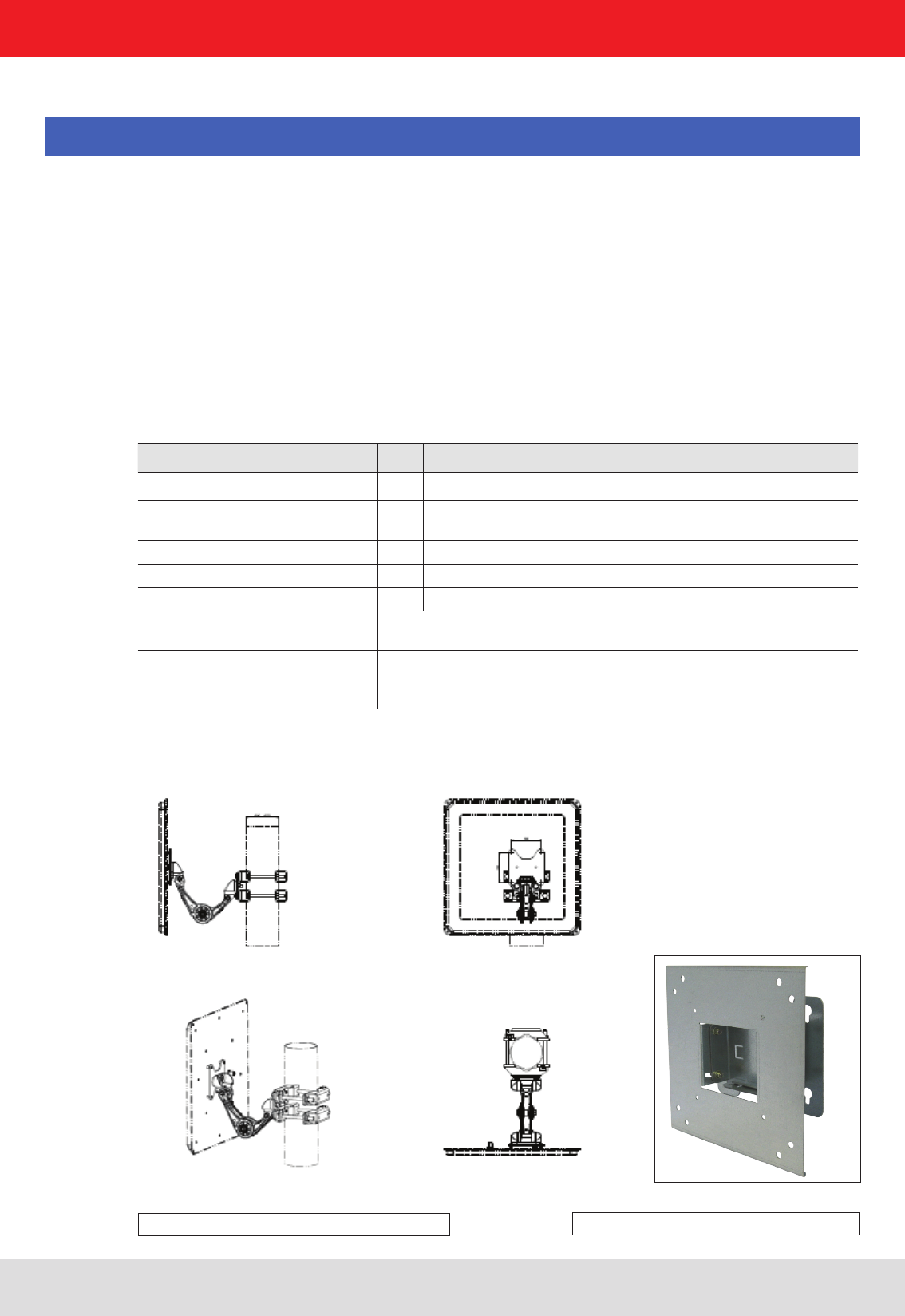
Wall/mast clamp for install RFID antennas and RRU4/ARU4 readers (up to 6.0 kg total weight).
Mounting plate with variours pre-drilled holes suitable for Wide range antennas ect.
Order number: 52010128
Max. load-bearing capacity kg 6,0
Adjustment range °± 30
± 30
Weight (unpacked) kg ca. 0,9
Dimensions of the clamp mm 200 x 200 x 125
Dimension of the packing mm 265 x 235 x 105
Material Clamp: galvanised sheet stell
Screw/hose clip: stainless steel
Items supplied Wall plate, mounting plate, mast clamp, hose clip, 8 screws M5x10,
8 shims, 4 screws M6*10
5.3. Wall/mast clamp
Selecting the installation location:
Before drilling the holes, make sure there are no electrial cables in the wall.
Risk if fatal injury due to electric shock !
Make sure that the wall / the mast has a sufcient capacity. Use the appropriate mounting hardware (not included).
You may need to strengthen the wall of your desired mounting location or use a different masts.
Note
5.3.1. Wall/mast clamp for RRU4/ARU4 Reader und RFID antennas
5. Installation
Figures 25: Wand-/Mastmontage 52010262 Figures 26: Wand-/Mastmontage 52010128
Installation manual antennas 40
Modications, misprints and errors excepted
English
5. Installation
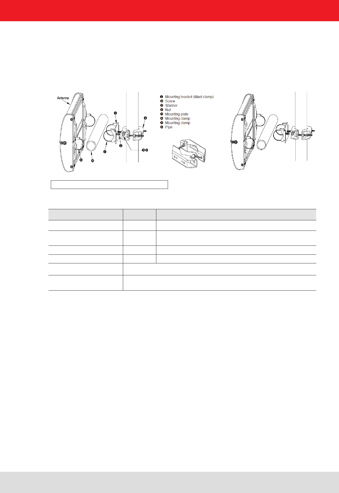
5.3.2. Mast clamp for Wide range 30° antennas
Mast clamp for install Wide range 30° antennas to 2 - 4.5 inch (50 - 115 mm) mounting structures.
Mounting plate with variours pre-drilled holes suitable for Wide range antennas ect.
Order number: 52010005
Max. load-bearing capacity kg
Adjustment range ° ± 90
Weight (unpacked) kg 1.5
Dimension of the packing mm 200 x 150 x 75
Material Stainless steel and galvanized steel; fasteners are stainless steel
Items supplied mounting bracket, 2x Sechsantkopfschrauben M8x20, 2x Unterlegscheiben
8mm, 2x Senkkantmutter M8, mounting plate, 2-Clamp Kit
Figures 27: Wand-/Mastmontage 52010005
Installation manual antennas 41
Modications, misprints and errors excepted
English
5. Installation
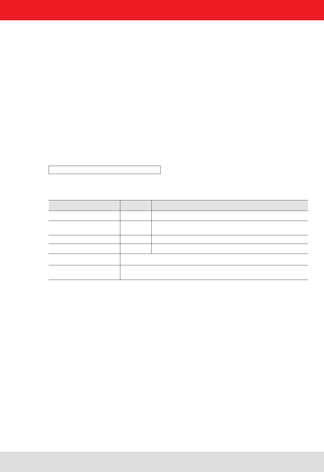
5.3.3. Mast mounting Ste for Wide Range 70° antennas and for RRU4/ARU4-Reader
Order number: 52010261
Max. load-bearing capacity kg 6,0
Adjustment range °± 30 Azimuth
± 45 Elevation
Weight (unpacked) kg ca. 0,6
Dimension of the packing mm 150 x 120 x 80
Material Stainless steel and galvanized steel; fasteners are stainless steel
Items supplied mounting bracket, 2x Sechsantkopfschrauben M8x20, 2x Unterlegscheiben
8mm, 2x Senkkantmutter M8, mounting plate, 2-Clamp Kit
Figures 28: Wand-/Mastmontage 52010261

Installation manual antennas 42
Modications, misprints and errors excepted
English
5.4. Assignment Wall/mast clamp to antennas and readers
5. Installation
Order No. Wall/Poll monting set
Order-No, antenna Typ antenna 52010005 52010128 52010261 52010262
52010086 WiRa 30° ETSI X
52010087 WiRa 30° FCC X
52010251 WiRa 40 linear ETSI X
52010252 WiRa 40 linear FCC X
52010078 WiRa 70° ETSI X X X
52010079 WiRa 70° FCC X X X
52010082 MiRa ETSI X
52010083 MiRa FCC X
52010172 S-MiRa ETSI/FCC X
52010193 WiRa-70-KRAI-ETSI X X X
52010194 WiRa-70-KRAI FCC X X X
52010227 WiRa-30-CSB-KRAI ETSI X
52010228 WiRa-30-CSB-KRAI FCC X
52010248 WiRa 30 linear ETIS X
52010249 WiRa 30 linear FCC X
Order No. Wall/Poll monting set
Order-No. Reader Typ-Reader 52010005 52010128 52010261 52010262
52010094 RRU4-ETG-E6 X X
52010095 RRU4-ETL-E6 X X
52010097 RRU4-ETG-U6 X X
52010099 ARU4-RS4-E6 X X
52010100 ARU4-ETG-E6 X X
52010101 ARU4-ETL-E6 X X
52010102 ARU4-RS4-U6 X X
52010103 ARU4-ETG-U6 X X
52010104 ARU4-ETL-U6 X X
52010180 RRU4-ELC-E6 X X
52010181 RRU4-ELC-U6 X X
52010225 ARU-ELK-E6 X X
52010226 ARU-ELK-U6 X X
Installation manual antennas 43
Modications, misprints and errors excepted
English
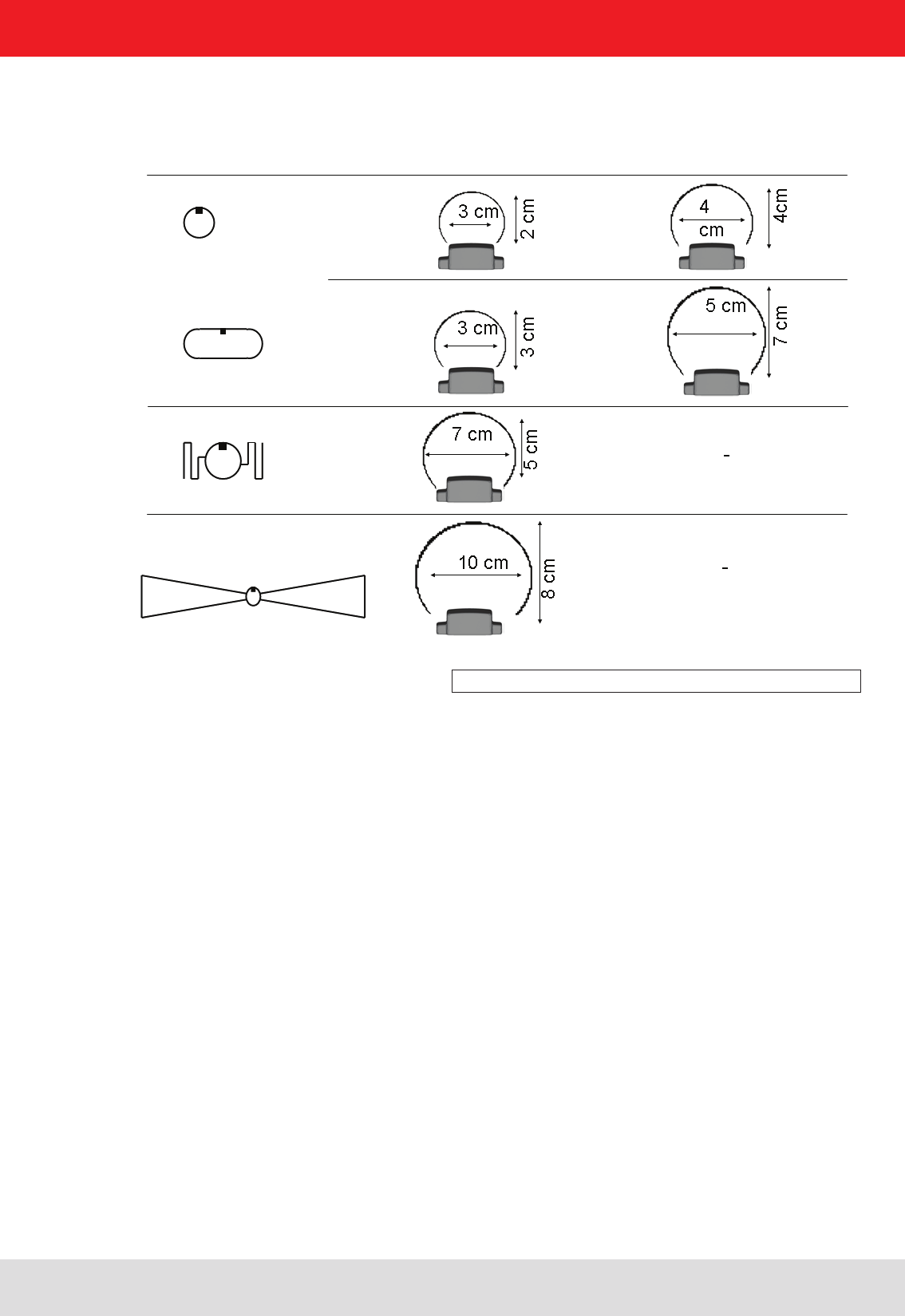
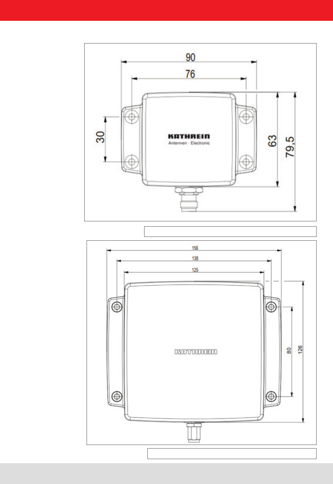
5.5. Installation drawings
Figure 29: Dimensios for U-LoRa/LoRa antenna (52010092, -84, -85)
Figure 30: dimensios for MiRa/S-Mira antenna (52010172, -82, -83)
5. Installation
Installation manual antennas 44
Modications, misprints and errors excepted
English
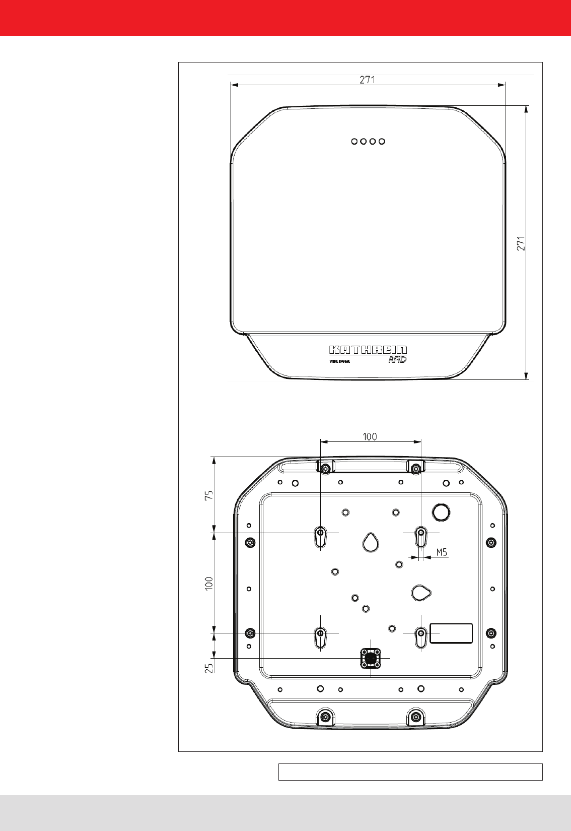
Figure 31: Dimensions for WiRa 70° antenna (52010078, -79)
5. Installation
Installation manual antennas 45
Modications, misprints and errors excepted
English
5. Installation
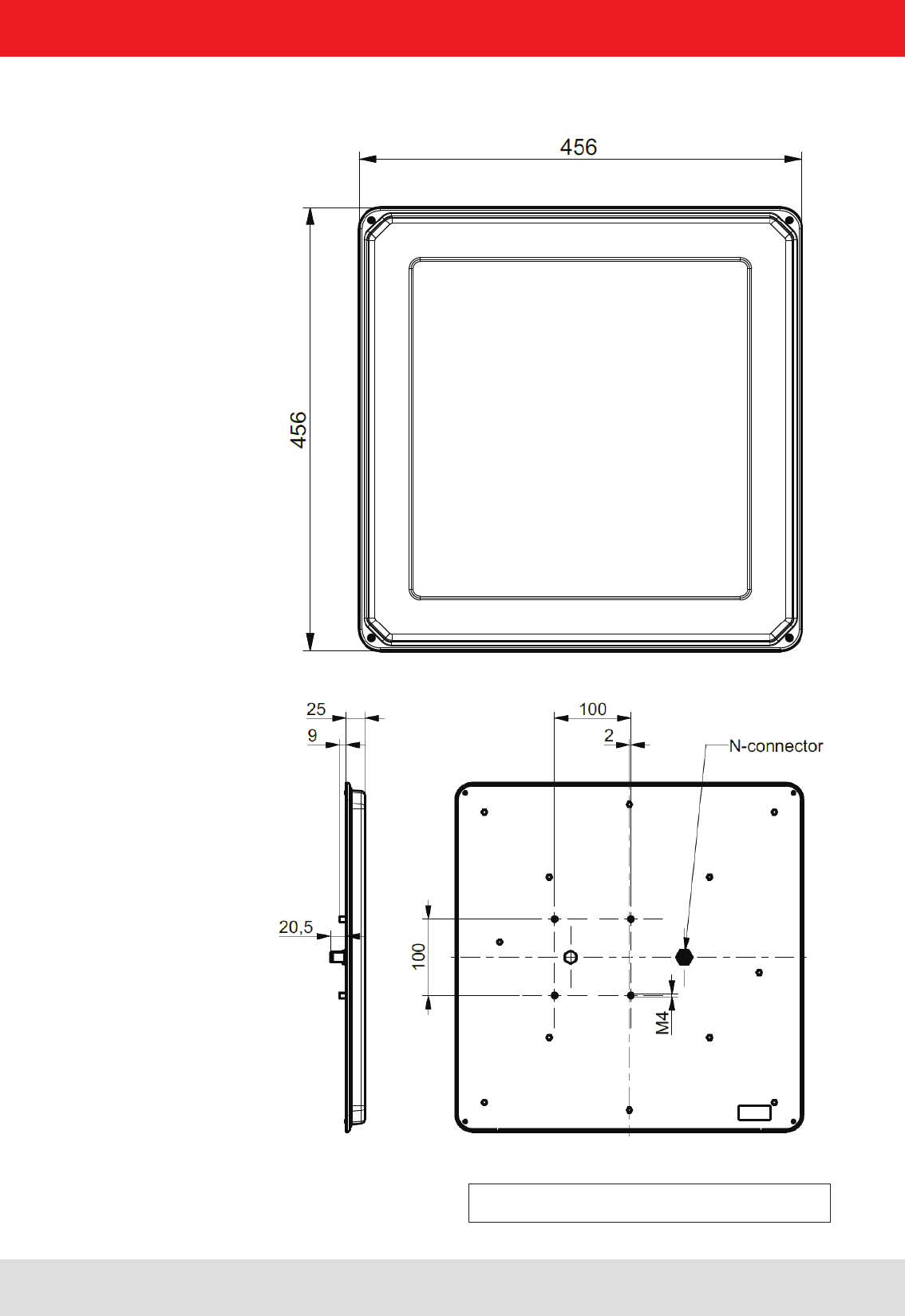
Bild 32: Abmessungen für WiRa 40° (52010251, -252)
Installation manual antennas 46
Modications, misprints and errors excepted
English
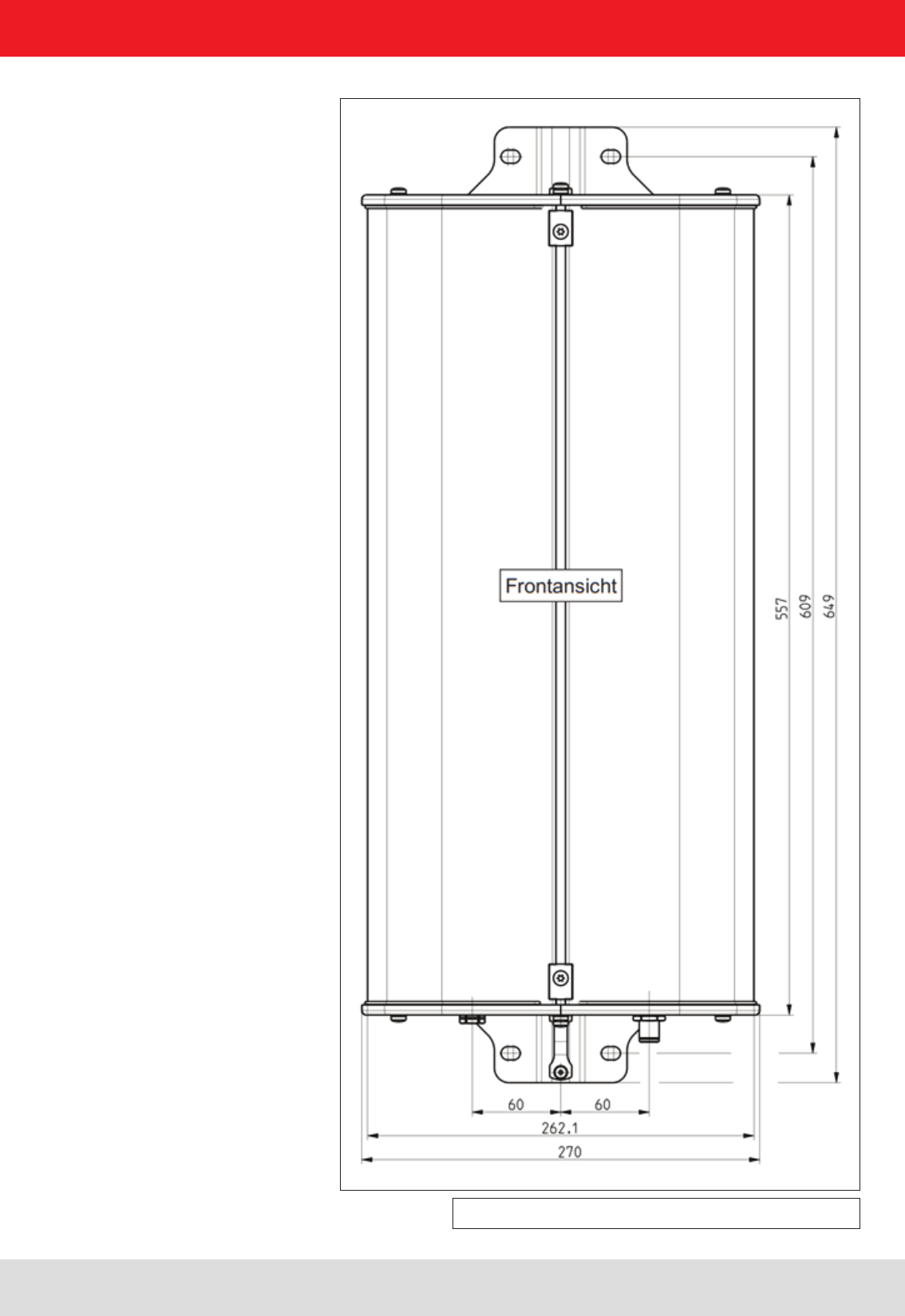
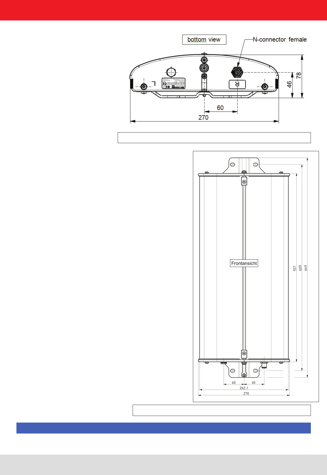
Figure 33: Dimensions for WiRa 30° antenna (52010086, -87
5. Installation
Installation manual antennas 47
Modications, misprints and errors excepted
English
Figure 35: Dimensions for WiRa-30-CSB-KRAI antenna (52010227, -228)
Figure 34: Note left / right installation WiRa-30-CSB-KRAI antenna (52010227,
-228)
5. Installation
Please note that the Beam „R“ is assigned (right) getting the connection side.
Note

Installation manual antennas 48
Modications, misprints and errors excepted
English
Address Contact
Kathrein RFID E-Mail: rd-sales@kathrein-rd.de
Kronstaudener Weg 1 Internet: www.kathrein-rd.de
D-83071 Stephanskirchen
8. Contact address