KATHREIN Sachsen ARU4ELCU6 UHF RFID Reader User Manual installation manual reader v1 04 en
KATHREIN Sachsen GmbH UHF RFID Reader installation manual reader v1 04 en
Contents
User Manual

Installation manual for
Kathrein RFID UHF-Reader
Installation manual Reader English
This document is valid for all Kathrein RFID readers and describes the construction and commissioning
of the readers.
Version 1.04 - Stand: 30.04.2015
date of creation: 01.06.2012
document no.: 936B057
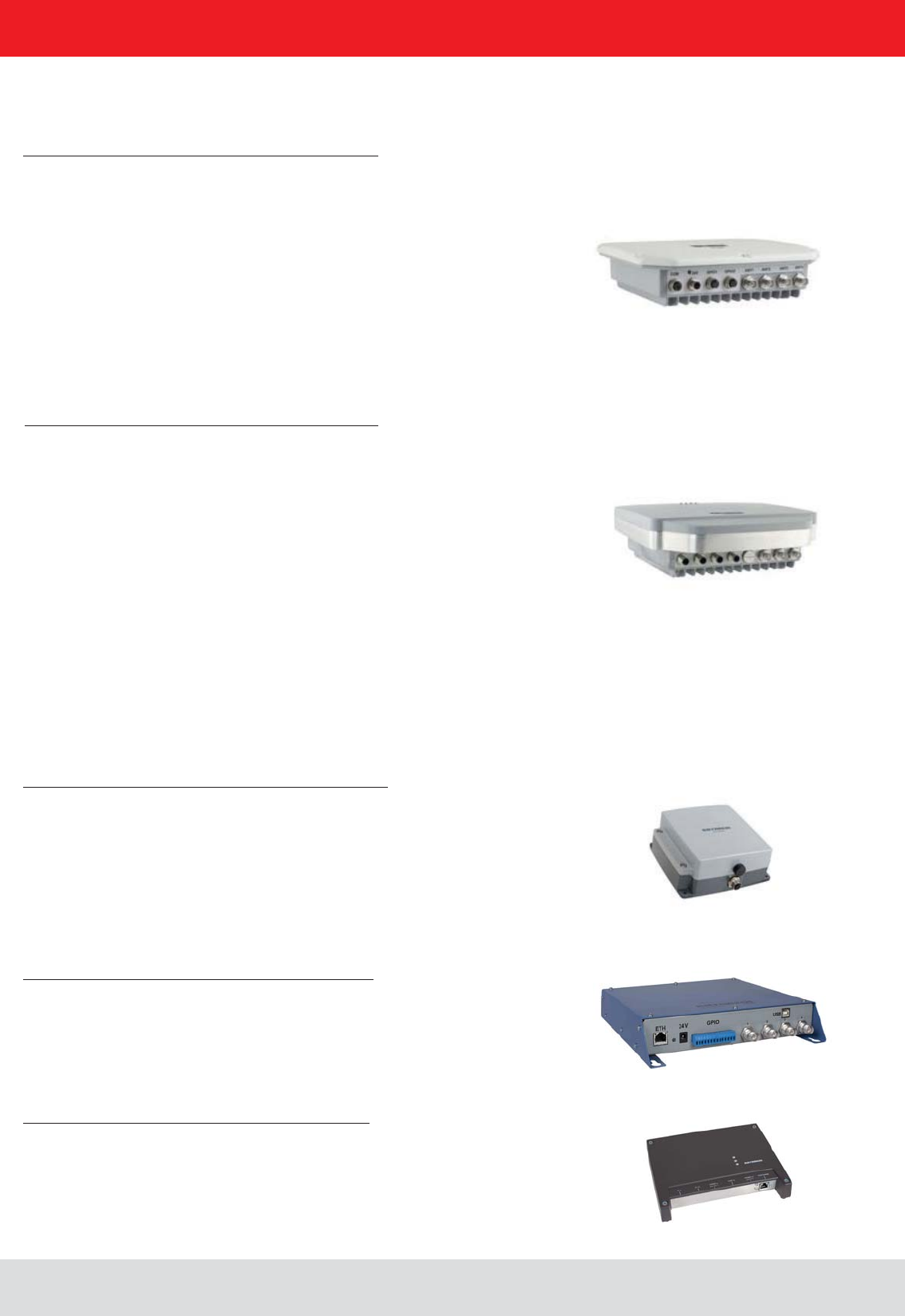
RRU4
ARU4
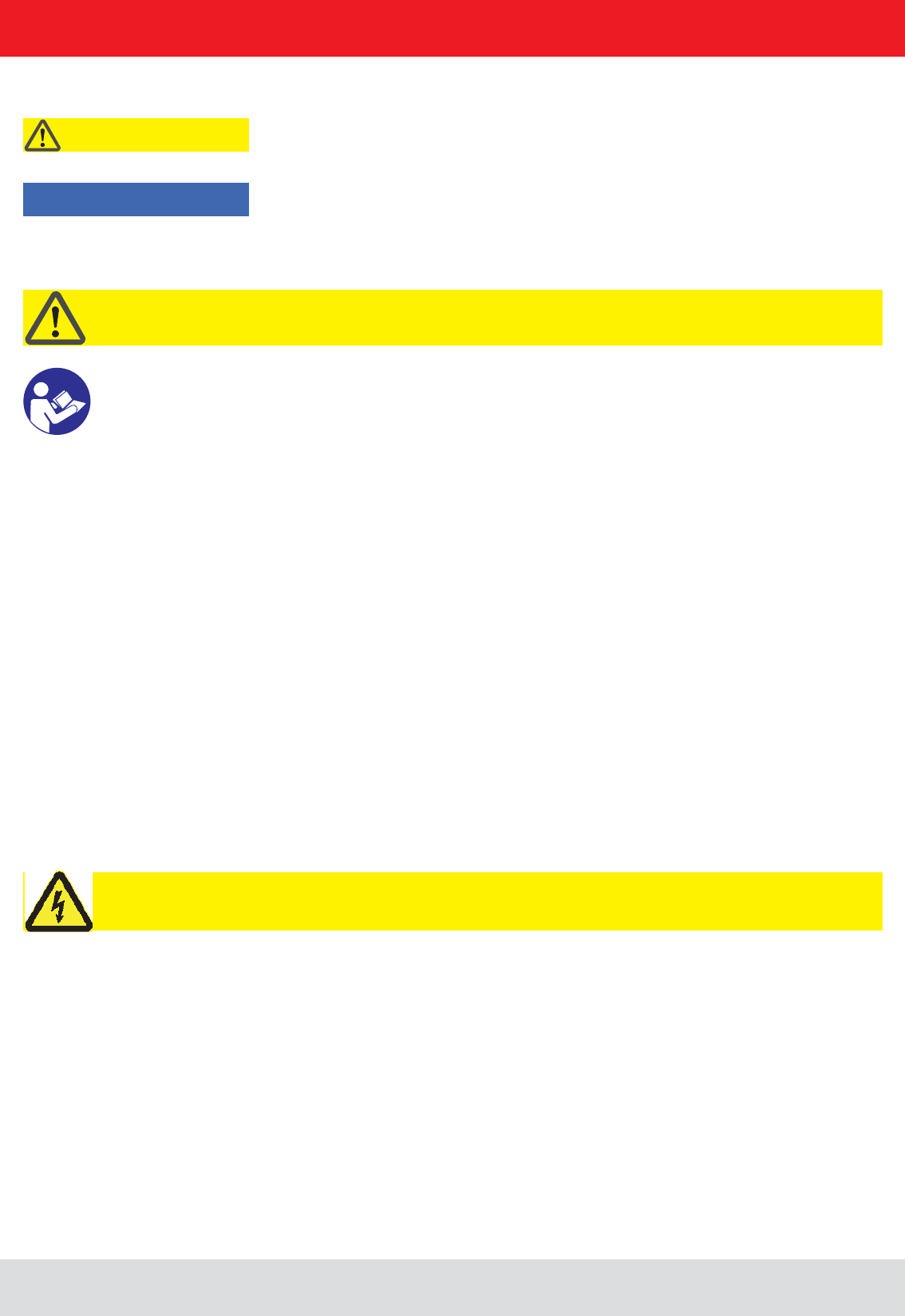
M-ARU
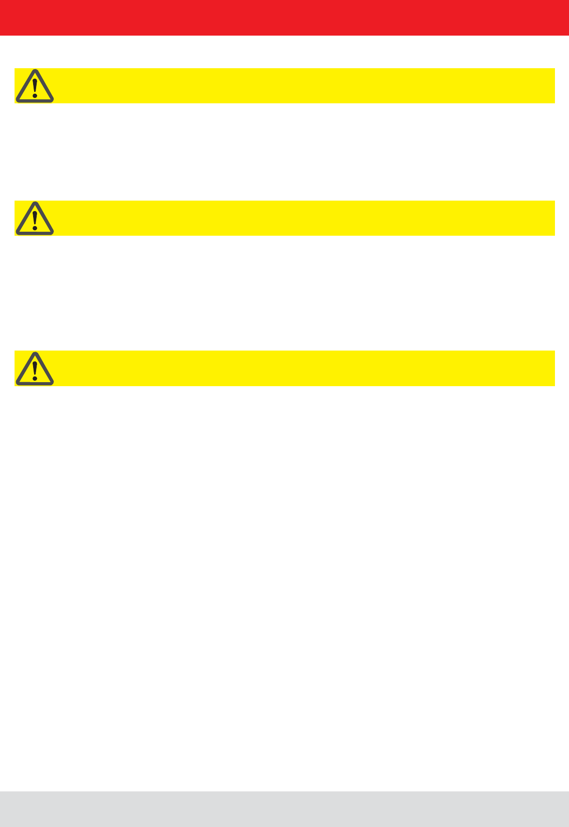
ERU
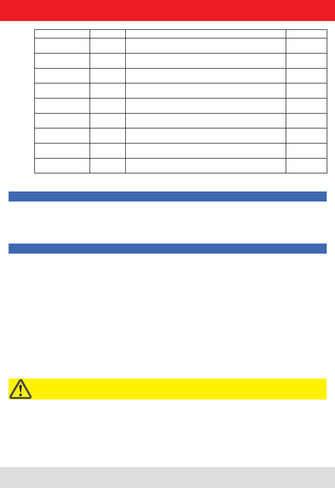
RDR
Installation manual Reader 2
EnglishInstallation manual Reader
This manual applies to the followings ARU4 types:
Type: Order number:
ARU4-RS4-E6 52010099
ARU4-ETG-E6 52010100
ARU4-ETL-E6 52010101
ARU4-RS4-U6 52010102
ARU4-ETG-U6 52010103
ARU4-ETL-U6 52010104
ARU4-RS2-E6 52010120
ARU4-RS2-U6 52010122
ARU4-ELK-E6 52010225
ARU4-ELK-U6 52010226
ARU4-ELC-U6 52010171
This manual applies to the followings M-ARU types:
Type: Order number:
M-ARU-RS232 ETSI 52010135
M-ARU-RS232 FCC 52010136
M-ARU-ETH-E6 52010198
M-ARU-ETH-U6 52010199
RFID-UHF-Reader
This manual applies to the followings RRU4 types:
Type: Order number:
RRU4-RS4-E6 52010093
RRU4-ETG-E6 52010094
RRU4-ETL-E6 52010095
RRU4-RS4-U6 52010096
RRU4-ETG-U6 52010097
RRU4-ELC-E6 © KRAI 52010180
RRU4-ELC-U6 © KRAI 52010181
This manual applies to the followings ERU types:
Type: Order number:
ERU-ETG-E4 52010190
ERU4-ETG-U4 52010191
This manual applies to the followings RDR types:
Type: Order number:
RDR-ETH-E4 52010200
RDR-ETH-U4 52010201

Installation manual Reader 3
English
Foreword and general information
The reproduction or distribution of this document or extracts from it in whatever form and by whatever means (electronic or mechanical)
for whatever purpose is permitted only with the prior written permission of Kathrein.
Kathrein accepts no liability for omissions or inaccuracies in this document or in relation to the provision or use of the information
contained in this document. Kathrein reserves the right to change the products described in this document and does not accept any
liability in relation to the application or usage of the products described in this manual.
Kathrein provides this document to its customers in connection with contacts of sale for the products described therein. If the person
in possession of this document, being a legal or natural person, is not a contractual sales partner of Kathrein, or Kathrein has not
intended him by other means as the recipient of the document and the information contained therein, the person in possession is hereby
informed that the use of this document is unlawful and a violation of the rights of Kathrein.
Copyright notice
The information in this manual was correct at the time of editorial deadline.
We reserve the right however to make changes at any time and without prior notice.
Scope
The information contained in this manual is intended for the support of the development process and as development guidance
for the customer. In addition this manual offers supporting information about the standards to be applied at the place of installation
General information
detailed technical data in order better to familiarise the user with the features of the reader.
In order to ensure a long working life and fault-free operation, this manual should therefore be read carefully and all the instructions
and information contained in it should be complied with.
Warranty
Switching on the AC or DC power supply prior to connecting the LAN cable is considered incorrect installation. Any functional defect
arising as a result is excluded from the warranty/guarantee. Before installing or servicing the reader, the person concerned must
have read the manual and understood its contents. Kathrein accepts no liability if the customer fails to implement the precautions
listed here. In such cases, any claims under the warranty/guarantee are void.
Disposal instruction
Electronic equipment is not classed as household waste and must be disposed of properly in accordance with
Directive 2002/96/EC OF THE EUROPEAN PARLIAMENT AND OF THE COUNCIL of 27 January 2003 on used
electrical and electronic equipment.
At the end of its service life, take this device for disposal at a designated public collection point.
Used batteries are special waste!
Do not put used batteries into your domestic waste; instead take them to a collection point for used batteries!
Further reading on this manual is as ((A)) in section 2.2. further reading or 7th list of references listed.

Installation manual Reader 4
English
List of Contents
Foreword and general information 3
List of Contents 4
1. Safety instructions/information 6
2. Introduction 9
2.1. The reader 9
2.2. RFID system 9
2.3. Kathrein RFID Antenna Interface (© KRAI) 11
2.4. Wide Range © KRAI antenna 12
2.5. SMSH © KRAI planar antenna module 12
2.6. Further reference material 13
2.7. Scope of supply 13
2.8. Accessories 14
3. Installation 15
3.1. Selecting the installation site 15
3.2. Installing the reader RRU / ARU 15
3.3. Installing the reader ERU 16
3.4. Installing the reader RDR 17
3.5. Installing the reader M-ARU 18
4. Connections and displays 19
4.1. Power supply 19
4.2. Ethernet connection 20
4.3. RS422-/485 connection 20
4.4. RS232 connection 20
4.5. ERU connection 21
4.6. RDR connection 21
4.7. M-ARU connection 22
4.8. UART transmission (RS232, RS422, RS485 or similar) 23
4.9. Ethernet transmission 25
4.10. Anschlüsse M-ARU, RS232, 25
4.11. Antenna Connection 29

Installation manual Reader 5
English
List of Contents
4.12. LED 29
4.13. Buzzer 29
5. Software 30
5.1. System requirements 30
5.2. Installation 30
5.3. Operation 34
6. Operating the reader 39
6.1. Communication 39
6.2. Application 46
6.3. Basic read functions 48
6.4. Basic writing functions 51
6.5. GPIO functions 53
6.6. Expert settings 58
6.7. Test Gen2 functions 63
6.8. © KRAI Setting 67
6.9. App Manager 70
6.10. Access Manager 70
6.11. Ethernet password 77
6.12. configuration password 79
7. Programming the Reader 80
7.1. Preparation 80
7.2. Using the examples with Windows 80
7.3. Using the examples with Linux 80
7.4. Using the examples with Linux on a PC 80
7.5. Using on an embedded system 80
7.6. Installation Embedded Linux Development Kit (ELDK) 81
7.7. Installation Linux application 82
8. List of references 85
9. Contact address 86
Installation manual Reader 6
English
1. Safety instructions/information
Key
Caution!
Note
Before starting installation work or replacing the unit, the accompanying manual must be read carefully and its
contents understood.
The detailed information in the data sheets and in this manual must be complied with carefully during installation and
operation of the reader!
concerned.
Connection, installation and maintenance work, as well as all other work on the unit, may only be carried out by
The unit may only be used for the purpose intended by the manufacturer.
Unauthorized changes to the unit and the use of spare parts and peripheral devices which are not sold or
exclusion of liability and make the manufacturer’s warranty/guarantee null and void.
The applicable version of the manufacturer’s warranty is that which was valid at the time of purchase. We accept
the unit.
Repairs may only be undertaken by personnel authorised to perform them. Opening or attempting to repair the
The manufacturer is not liable for accidents caused by the user opening the unit!
When carrying out work on the unit, the valid safety regulations must be complied with.
Supply voltage
Make sure that the mains cable (power supply cable) is not damaged. If the mains cable is damaged, the device
the power supply unit supplied!
Risk of fatal injury due to electric shock!
The device may be operated only at the stated supply voltage (see the rear of the device or external power supply unit)!
General safety notes
Important!
from minor to severe and/or damage to the unit.
of the unit functions.
Important!
Installation manual Reader 7
English
1. Safety instructions/information
CE marking for the Kathrein RFID reader with type designation "E6"
Appropriate means are provided to dissipate the heat generated within this equipment. The device must however not be
Ventilation
Protect the device from moisture, dripping water and spraying water. The device must not be placed close to sources of
heat, exposed to direct sunlight or operated in a damp environment. The device may not be operated only is moderate
device! 1)
This reader is designed “E6” for operation as per EN 302208. When the unit is operated with antennas connected,
the human exposure regulations in accordance with EN 50364 must be complied with. Ensure a minimum clearance
of 20 cm between the antenna and the human body, and comply with the operating instructions for RFID antennas. In
some circumstances, heart pacemakers may suffer interference if wearers are close to the antenna when the unit is
in operation (reader and antenna). In case of doubt, the people affected are requested to contact the manufacturer of
their pacemaker or their doctor.
The reader output power must be reduced as a function of the antenna cable length and the antenna gain.
Marking for the Kathrein RFID reader with type designation "U6"
This device complies with part 15 of the FCC Rules and with Industry Canada license-exempt RSS standard(s). Opera-
must accept any interference received including interference that may cause undesired operation.
Industry Canada
Le présent appareil est conforme aux CNR d‘Industrie Canada applicables aux appareils radio exempts de licence.
L‘exploitation est autorisée aux deux conditions suivantes : (1) l‘appareil ne doit pas produire de brouillage, et (2)
l‘utilisateur de l‘appareil doit accepter tout brouillage radioélectrique subi, même si le brouillage est susceptible d‘en
compromettre le fonctionnement.
Under Industry Canada regulations, this radio transmitter may only operate using an antenna of a type and maximum
(or lesser) gain approved for the transmitter by Industry Canada. To reduce potential radio interference to other users,
the antenna type and its gain should be so chosen that the equivalent isotropically radiated power (e.i.r.p.) is not more
than that necessary for successful communication.
This radio transmitter has been approved by Industry Canada to operate with the antenna types listed at page 8 with
the maximum permissible gain and required antenna impedance for each antenna type indicated. Antenna types not
included in this list, having a gain greater than the maximum gain indicated for that type, are strictly prohibited for use
with this device.
invalidate the FCC permit for the operation of this unit.
Important!
Important!
Important!
Installation manual Reader 8
English
1. Safety instructions/information
Note
Following corresponding tests, it has been ascertained that this unit adheres to the limit values for class B digital
units in accordance with part 15 of the FCC regulations. These limit values are intended to provide private user's
systems with appropriate protection against harmful radio interference. This unit generates and uses energy
in the radio frequency range and is also able to radiate this; if it is not installed and used in accordance with the
regulations, the unit may cause harmful radio communication interference. However, there is no guarantee that
which can be ascertained by switching the unit on and off, we recommend that the user attempts to rectify this
interference via one or more of the following measures:
- Realign the receive antenna or change its position.
- Plug the unit into a socket in a current circuit other than that to which the receiver is connected.
- Seek advice from the retailer or an experienced radio/television technician.
Note
To meet part 15 of the FCC regulations in the United States, the system must be properly installed to guarantee
system in any other combination (e.g. several antennas which transmit the same information in the same location)
is expressly prohibited.
Note regarding proper installation:
Important!
FCC RF Radiation Exposure Statement
This equipment complies with FCC RF radiation exposure limits set forth for an uncontrolled environment.
This equipment should be installed and operated with a minimum distance of 20 centimeters between the radiator and
your body.
This equipment complies with IC RSS-102 radiation exposure limits set forth for an uncontrolled environment.
This equipment should be installed and operated with minimum distance 20cm between the radiator & your body.
Type Order-No. Shortened designation Gain
WiRa 30° FCC 52010087 Wide Range-Antenna FCC, 902-928 MHz, 30° circular 11dBiC/ 8DBi
WiRa 70° FCC 52010079 Wide Range-Antenna FCC, 902-928 MHz, 70° circular typ. 11dBi
MiRa FCC 52010083 Mid Range-Antenna FCC, 902-928 MHz, 1000° circular 2.5dBi
S-MiRa ETSI/FCC 52010172 Short-Range-Antenna FCC, 865-928 MHz, 100° circular typ -10dBi
U-LoRa ETSI/FCC 52010092 Ultra Low Range-Antenna FCC, 865-928 MHz -30dBi
LoRa FCC 52010085 Low Range-Antenna FCC, 902-928 MHz -15dBi
WiRa-30-linear-FCC 52010249 Wide Range-Antenna 30° linear FCC, 902-828 MHz, 30° linear typ. 11dBi
WiRa-40-linear-FCC 52010252 Wide Range-Antenna 40° linear FCC, 902-828 MHz, 40° linear typ. 13dBi
SMSH-30-30ETSI-
FCC-Antennenmodul 52010219 Smart Shelft-Antenna, 865-928 MHz, non cascadable -7dBi
Installation manual Reader 9
English
2. Introduction
2.2. RFID system
An RFID system consists of the control computer of the actual reader, antennas, antenna connection cables and the
The tags consist of an antenna and a small chip. The chip is the true carriers of the information,
with new information.
To read the tag information, the reader sends an RF carrier by an active antenna and thus supplies the tags in the RF
Upon successful completion of the inventory, the EPC number of each tag can be read and sent to the PC. Additional
information can be attached to the EPC, for example the antenna which read it the time point at which it was read.
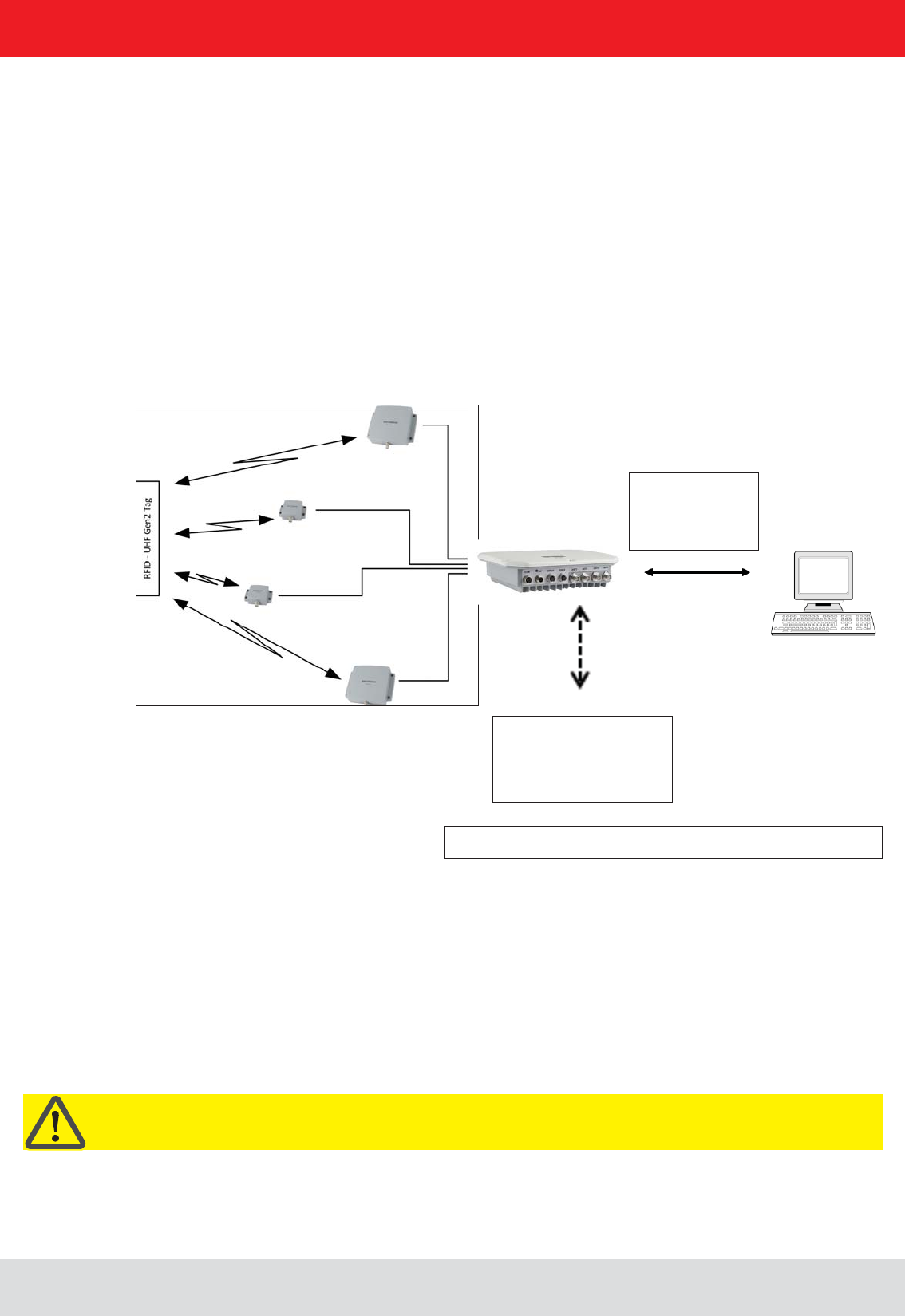
Figure: continuous operation ETL and ELC RFID system
By the ETL and ELC
Reader is an industrial
PC with Linux operating
system is integrated.
RS232
RS422/485
Ethernet
2.1. The reader
and passive RFID tags in the frequency range from 865 to 868 MHz for Europe type “E6” and 902 to 928 MHz for the
American market type “U6”. As supplied the unit can read and write tags in accordance with the EPC-Gen2 standard.
Additional protocols can be loaded using software updates.
The device has a maximum of four external antenna ports for connection of the transmission/reception antennas for
communication with RFID tags.
For integration into a variety of infrastructures, the device has different communication interfaces depending on the
variant. The power supply is provided by a 4-pin M12 panel connector in A coding.
Important!
The reader operates using the frequency hopping process, so as to avoid faults and interference between readers.
Within the FCC area this procedure is mandatory. The readers changes its transmission frequency randomly,
with equal distribution across the 52 available channels. Each channel is used for max. 400ms in an interval of 20s.
Installation manual Reader 10
English
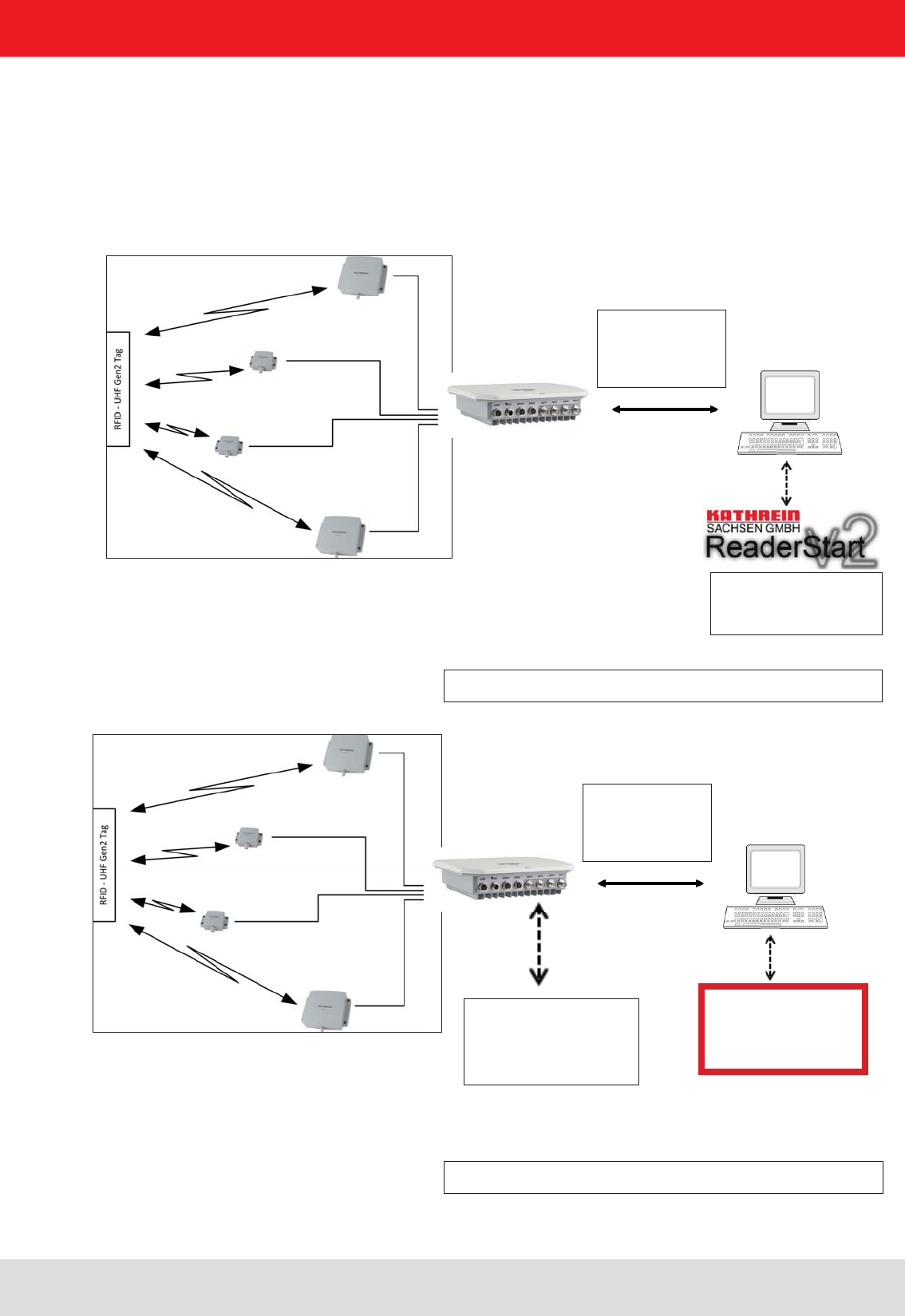
For testing and parameterizing the reader the Demo Software“Reader Start v2”can be used.
The communication between the“Reader Start v2” and the reader is based on the DLL, which includes the commu-
The DLL includes all the relevant commands and functions, which are needed to control the reader
RS232
RS422/485
Ethernet
By the ETL and ELC
Reader an industrial PC
with Linux Operating
System is integrated.
RS232
RS422/485
Ethernet
Figure: Continuous operation of the ETL and ELC RFID system
The control software
must be created by
the user.
network connection is possible.
The demo software
Reader Start is included.
2. Introduction
Installation manual Reader 11
English2. Introduction
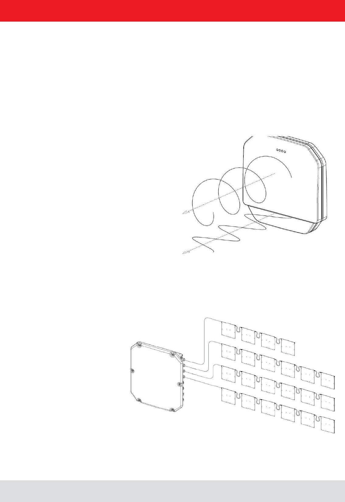
2.3. Kathrein RFID Antenna Interface © KRAI
By using Kathrein © KRAI antennas, reading rates can be increased by 33% compared to simple circular
antennas.
The Kathrein-RFID Antenna Interface © KRAI consists of a digital control bus, which enables connection
between the RFID reader and the RFID antennas in order to allow control and regulation tasks in remote
antennas.
antenna characteristics.
Due to this, four different polarizations can be selected for the new 70° Wide Range antenna (type 52010193
WIRA-70-KRAI-ETSI): RHCP / LHCP/ horizontal linear / vertical linear
One can choose between static polarization and automatic switch-over. As the Kathrein-RFID Antenna In-
terface © KRAI is transmitted over the standard antenna cable, no additional lead or connection is required
to control the new antenna types.
The Kathrein RFID © KRAI system permits the cascading of up to 8 SMSH antennas at a single antenna
port. This allows selective access to up to 32 individual antennas. This allows the reading result to be linked
to the antenna recognition (e.g. antenna 3 (5)) and be output.
With the new © KRAI product series Kathrein has introduced a revolutionary system.
Installation manual Reader 12
English
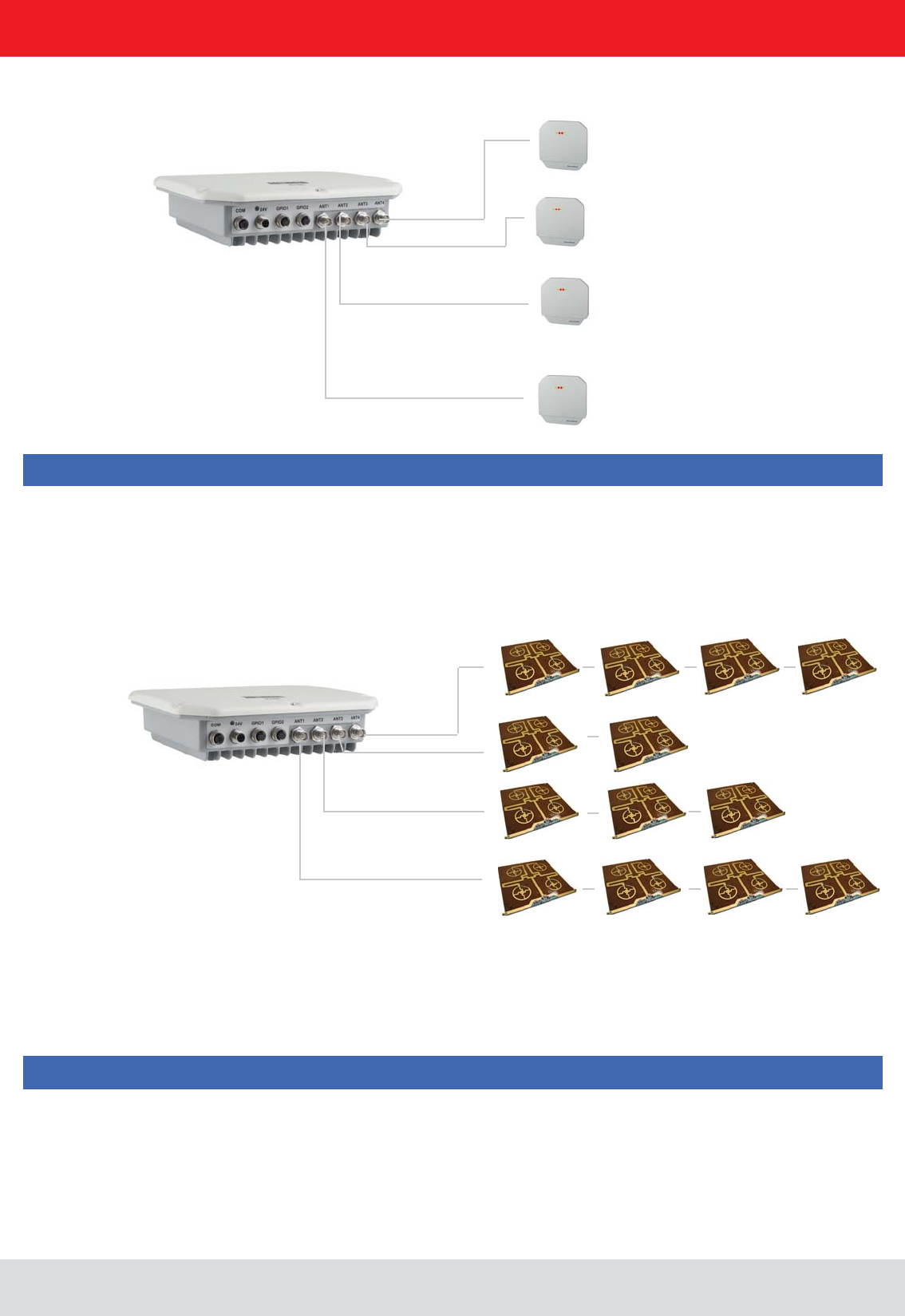
2.4. Wide Range © KRAI antenna
are release 2.40 or higher.
Note
Note
WiRa-70-KRAI antennas cannot be cascaded.
A maximum of 8 SMSH antennas can be cascaded per rea-
der port.
2.5. SMSH © KRAI planar antenna module:

Installation manual Reader 13
English
2.6. Further reference material
EPCGlobal standards of GS1 is necessary ((E)). This standard describes the principle of operation of the interface
between the tag and reader.
Reader” ((B))
The reader is controlled via the Kathrein-Reader protocoll (KBRP). The document “communication protocol” ((A)) in the
current version contains a detailed description of the protocol
Note
The versions of the documents must match the software version of the reader. The CD supplied contains the current
2.7. Scope of supply
The package includes a CD next to each reader with a parameter, and test software (Reader Start), programming
examples, DLL and operating
((E)) EPCTM Radio-Frequency Identity Protocols Class-1 Generation-2 UHF RFID in version V1.2.0 :
www.epcglobalinc.org
((A)) for software developers
((B)) for commissioning
((C)) Setup and installation
"installation manual antenna“ ((D)) Setup and installation
((E)) for software developers
((F)) for software developers
Installation manual Reader 14
English
2. Introduction
- Cable sets (without antenna cable)
Order number Type for Series Product type
52010125 CK-RRU RS4 RRU4/ARU4 Power supply cable, RS 422/485, GPIO, length 1.5 m
52010126 CK-RRU ETG RRU4/ARU4 Power supply cable, Ethernet interface cable, GPIO-cable,
length 1.5 m
52010189 CK-M-ARU RS M-ARU Combination cable for power supply GPIOs, RS232 interface
length 1.5 m
52010209 CK-M-ARU PoE M-ARU Combination cable for power supply and PoE interface,
length 1.5 m
52010238 R-CC 10 ETH RRU4/ARU4/
M-ARU
Ethernet Connecting Cable, length 10 m
52010239 R-CC 10 GPIO RRU4/ARU4 GPIO Connecting Cable, length 10 m
52010240 R-CC 10 DC RRU4/ARU4 DC power supply Connecting Cable, length 10 m
52010241 R-CC 10 RS M-ARU Connecting Cable M-ARU, length 10 m
2.8. Accessories
The following accessories are available for the reader (if you have questions about the accessories, please contact
- Antennas: For use with UHF-RFID antennas; we recommend the Kathrein antenna types ULoRa, LoRa,
MiRa, WiRa. These antenna types are available for all frequency ranges.The mentioned types of antennas are
available for all frequency ranges and in screwed condition tight IP 65.
Order number Type Connector 1 Connector 2 Lenght (cm)
52010174 R-AC 3 TNC-TNCR
TNC TNC Reverse
52010175 R-AC 6 TNC-TNCR
52010176 R-AC 10 TNC-TNCR
52010177 R-AC 15 TNC-TNCR
52010250 R-AA N-TNC N-Socket TNC (socket)
52010090 R-AC 3 SMA-TNCR SMA (socket) TNC (socket) RG 58, 300
52010208 R-AC 05 SMA-SMA SMA (socket) SMA (socket) RG 58, 50
- Antenna cable
Order number Type Product type
52010178 R-AA TNC-N(f-m) Adapter TNC-N (f-m)
52010243 R-AA TNC-SMA (f-m) Adapter SMA (f-m)
- Antenna adapter

Installation manual Reader 15
English
- Mounting Accessories
- Protective Covers
Order number Type Product type
52010179 R-RPA 115-230V/24V RRU / ARU 230V power supply with safty plug (Lörar);
24V DC power supply with M12 socket 4-pin, A-coded
52010192 R-ERPA 115-230V/24V ERU 230V power supply
24V DC cable plug connector 2.5 mm
Order number Type Product type
52010127 Protective covers set for the
RRU and ARU reader series
Accessories for RRU4/ARU4 reader with screw caps for
3x antenna input (R-TNC) and 2x digital (M12)
- Readers power supply
- Montageset und Wand-/Masthalterung
Bestellnummer Typ Bestehend aus
52010005 MK-AMB-100-Outdoor Poll Mount Kit for 30° WiRa antennas
52010128 MK-WPM-100-100-Outdoor Wall/Pole Mount Kit for WiRa 70 ° an-
ennes and RRU4/ARU4-Readern
52010261 MK-WM-100-100-Indoor Wall Mount Kit for WiRa 70°antennas and
RRU-, ARU- Reader; Indoor
52010262 MK-WPM-100-100-Outdoor Wall/Pole Mount Kit for WiRa 40°antennas; Outdoor
2. Introduction
Installation manual Reader 16
English
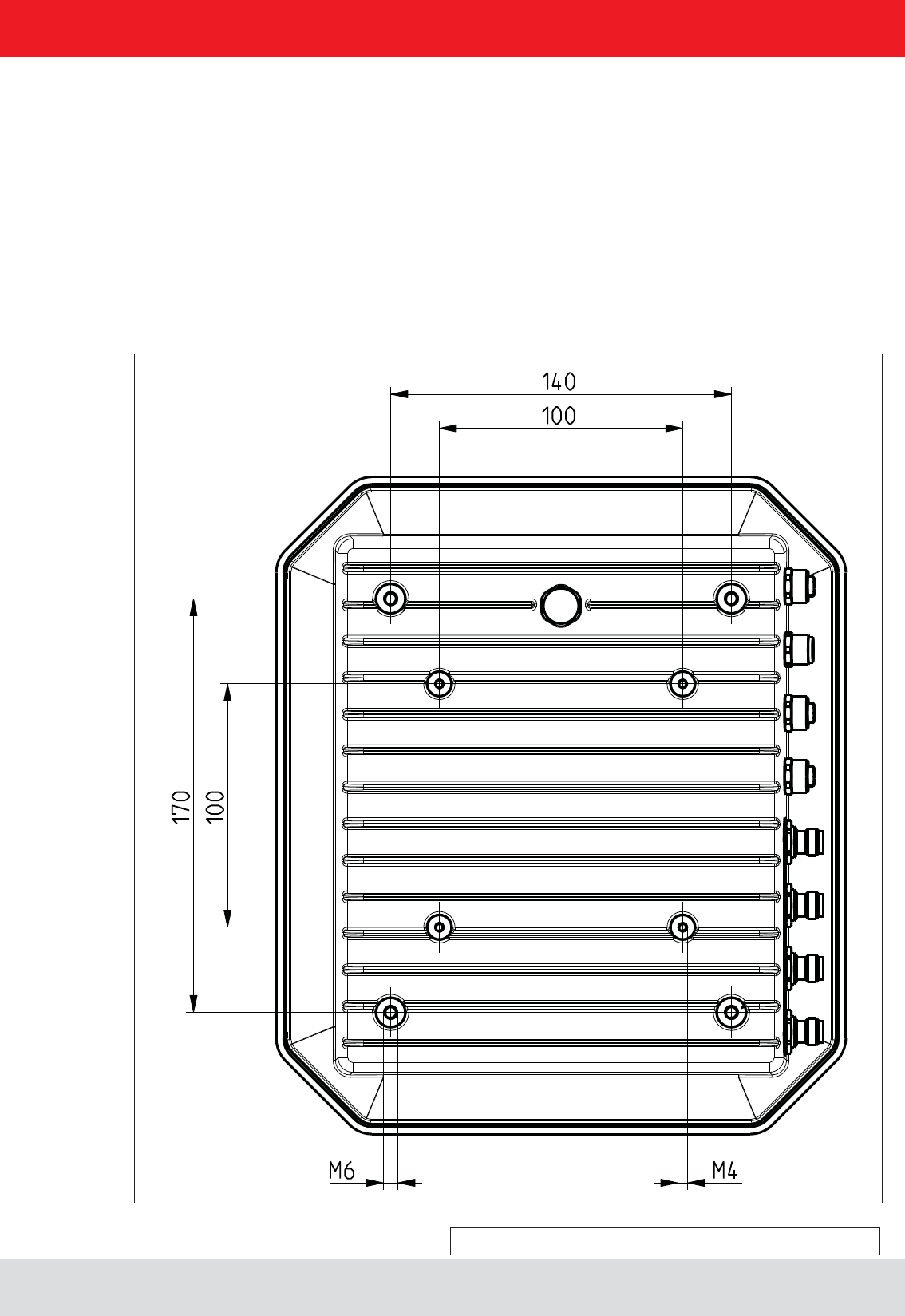
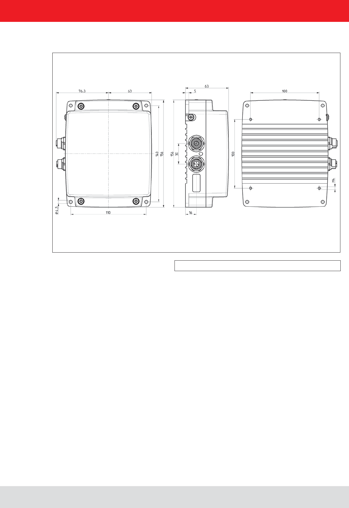
Figure: Far side RRU4 with dimensions
(M6 x 10 screw)
3.1. Selecting the installation site
(ERU and RDR).
generated by the device. Do not install it close to external sources of heat. The maximum operating temperature listed in the
3.2. Installing the reader
The device has threaded holes at the rear for attaching the reader. The dimensions of the holes pattern can be
found in the drawing below. For ease of installation a bracket is available as an accessory, which offers the option of
mounting on a mast or wall.
3. Installation
Installation manual Reader 17
English
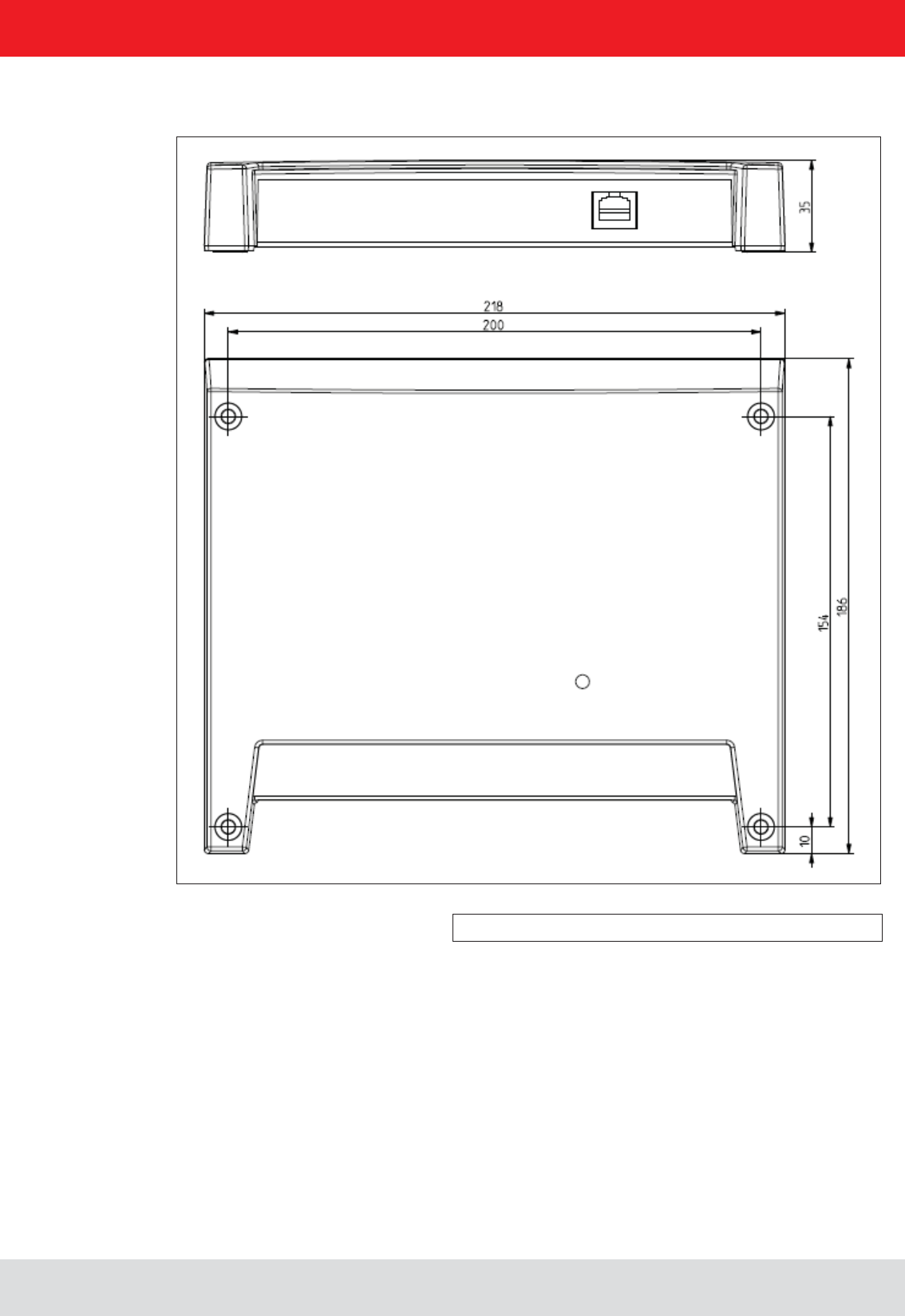
Figure: ERU with dimensions
3.3. Installing the reader ERU
3. Installation
Installation manual Reader 18
English
Figure: RDR with dimensions
3.4. Installing the reader RDR
3. Installation
Installation manual Reader 19
English
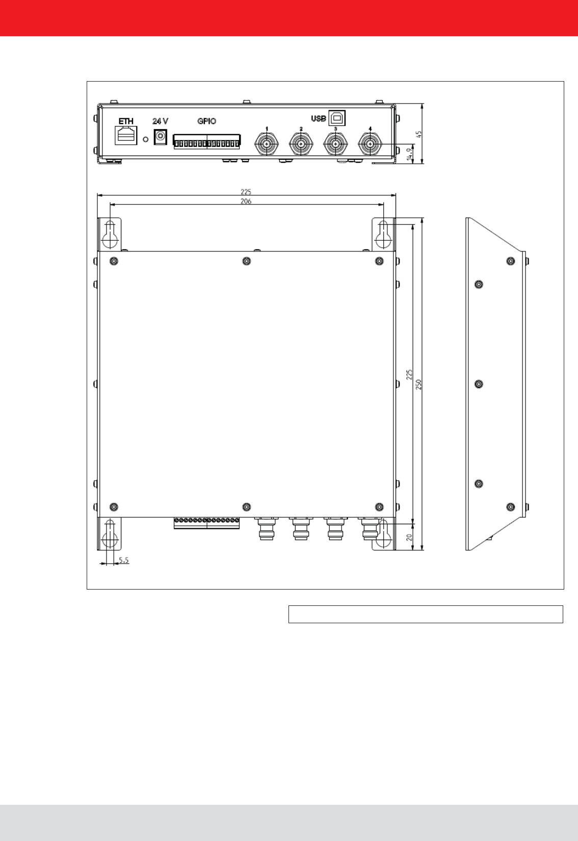
Figure: M-ARU with dimensions
3. Installation
3.5. Installing the reader M-ARU
Installation manual Reader 20
English
4. Connections and displays
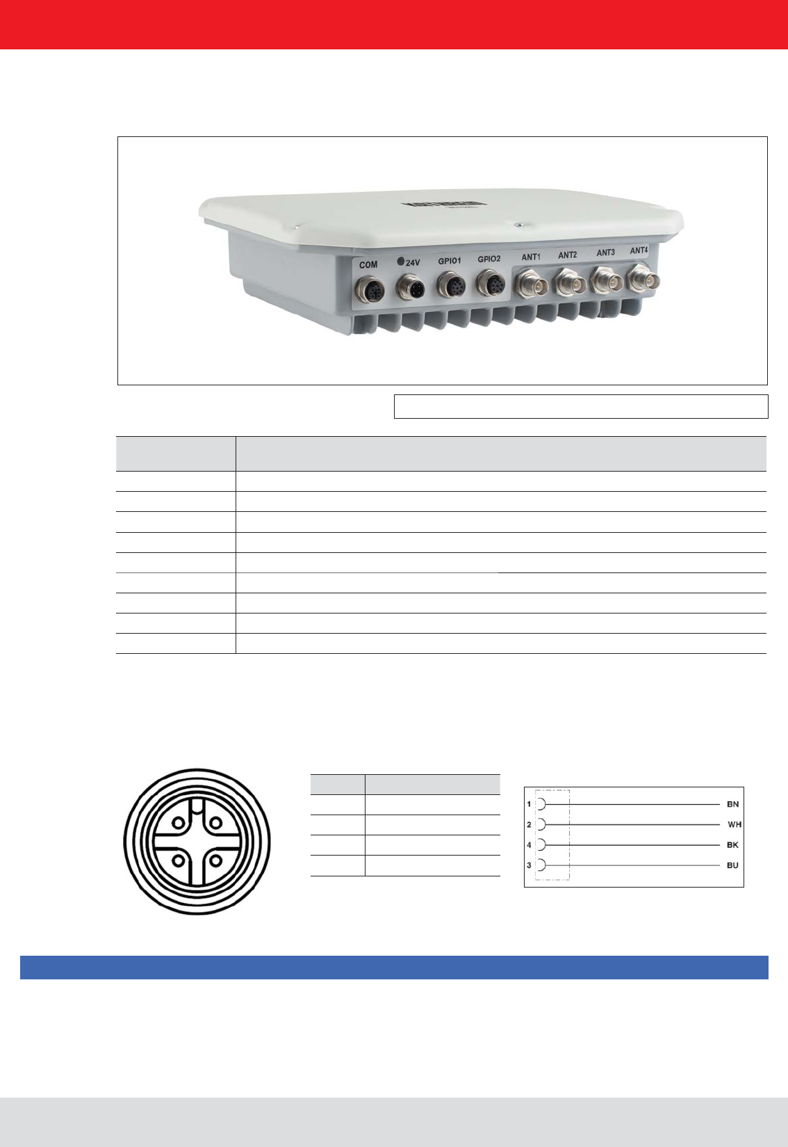
Figure: General view of the RRU4
2 1
3 4
PIN Allocation
1 +24 V DC
2
3 GND
4
Allocation of the power cable (Order-No.. 52010125 und 52010126)
Depending of the device variant, the reader has various connection options. The illustration below shows an RRU
and ARU standard reader with all its connection options. Details of the connections and the pin assignments of plugs
and sockets are provided in the following pages.
Sockets, from
left to right Description
1 Communication connection: M12 (depending on the device variant)
2 Power supply connection: M12 male, 4-pin, A-coded
3 GPIO connection 1: M12 female, 8-pin, A-coded
4 GPIO connection 2: M12 female, 8-pin, A-coded
5 Antenna connection 1: R-TNC 50 Ohm
6 Antenna connection 2: R-TNC 50 Ohm
7 Antenna connection 3: R-TNC 50 Ohm
8 Antenna connection 4: R-TNC 50 Ohm
Status indicators: 3 coloured LEDs (red, green, orange)
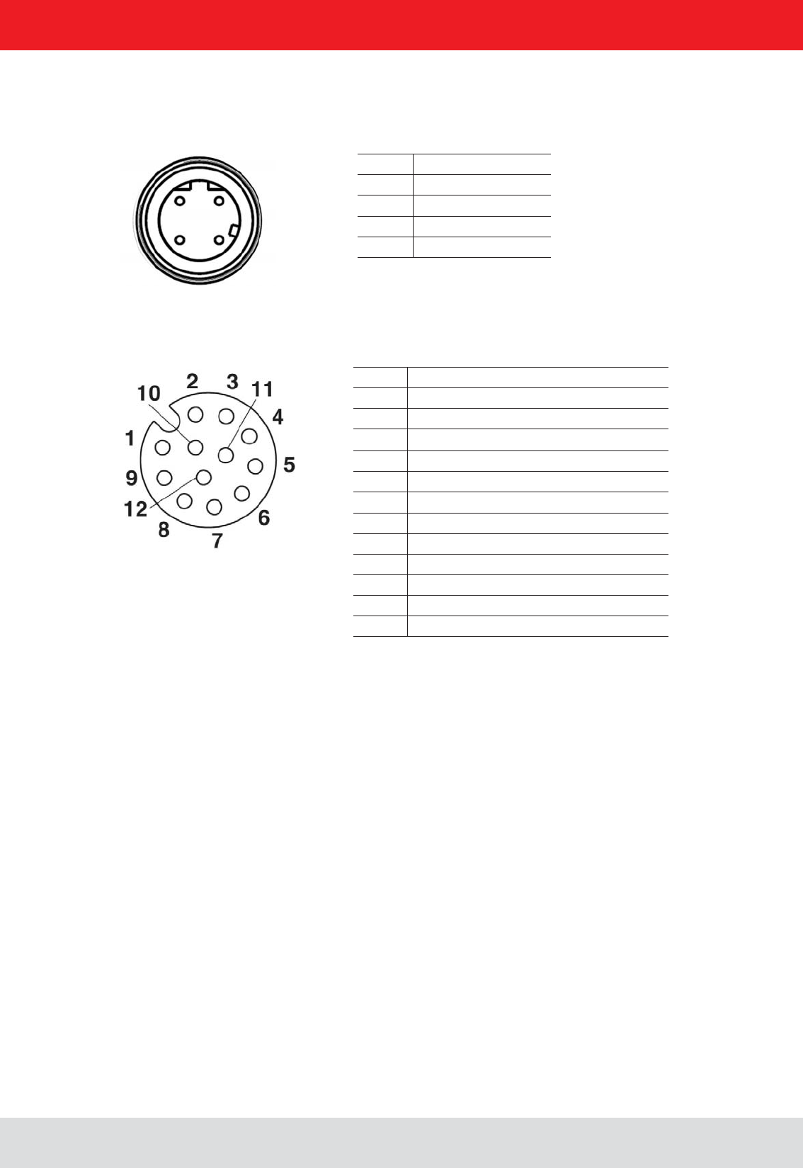
4.1. Power supply
The power supply is arranged as a four-pin round-pin plug with and M12 connection thread in A-coding.
Only power supply units with power limitation are approved for operation with the device. This means that the
secondary side of the power supply unit is limited to a power of maximum 100 W.
Note
Installation manual Reader 21
English
PIN Allocation
1 TD+
2 RD+
3 TD-
4 RD-
1 2
4 3
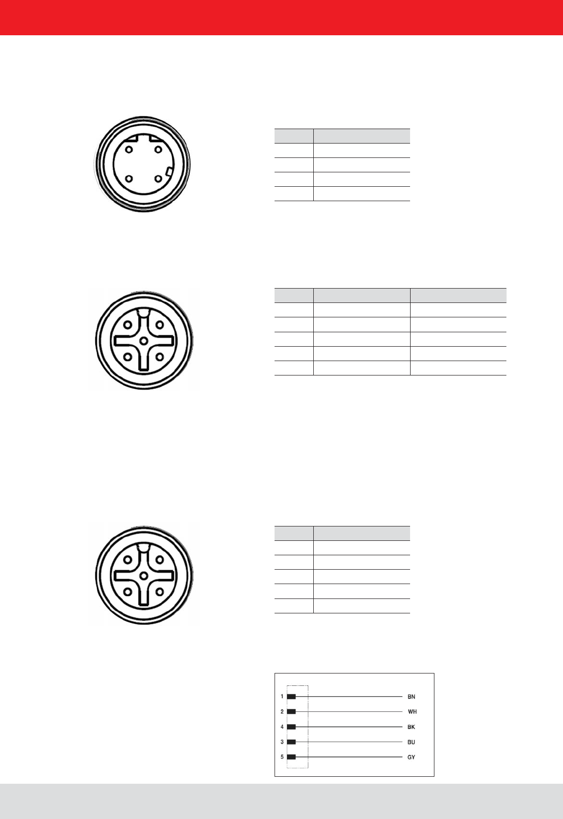
PIN Allocation RS422 Allocation RS485
1 RxD+ RxD/TxD+
2 RxD- RxD/TxD-
3 TxD+
4 TxD-
5 GND GND
1 2
4 3
5 Zentral-Pin
PIN Allocation
1 CTS
2 RxD
3RTS
4 TxD
5 GND
1 2
4 3
5 Zentral-Pin
Allocation of the serial interface cable (Order-No. 52010125) valid for RS232, RS422/485
4. Connections and displays
4.2. Ethernet connection
This data interface is arranged as a 4-pin M12 socket with D-coding. Only shielded cables may be used.
4.3. RS422/485 connection
This interface is arranged as a 5-pin M12 socket with A-coding. Only shielded cables may be used.
The interface card of the reader is equipped with a combined RS485/RS422 interface. The changeover between
are connected to RX.
4.4. RS232 connection
This interface is also arranged as a 5-pin M12 socket with A-coding. Only shielded cables may be used.
Installation manual Reader 22
English
4. Connections and displays
4.5. ERU connection
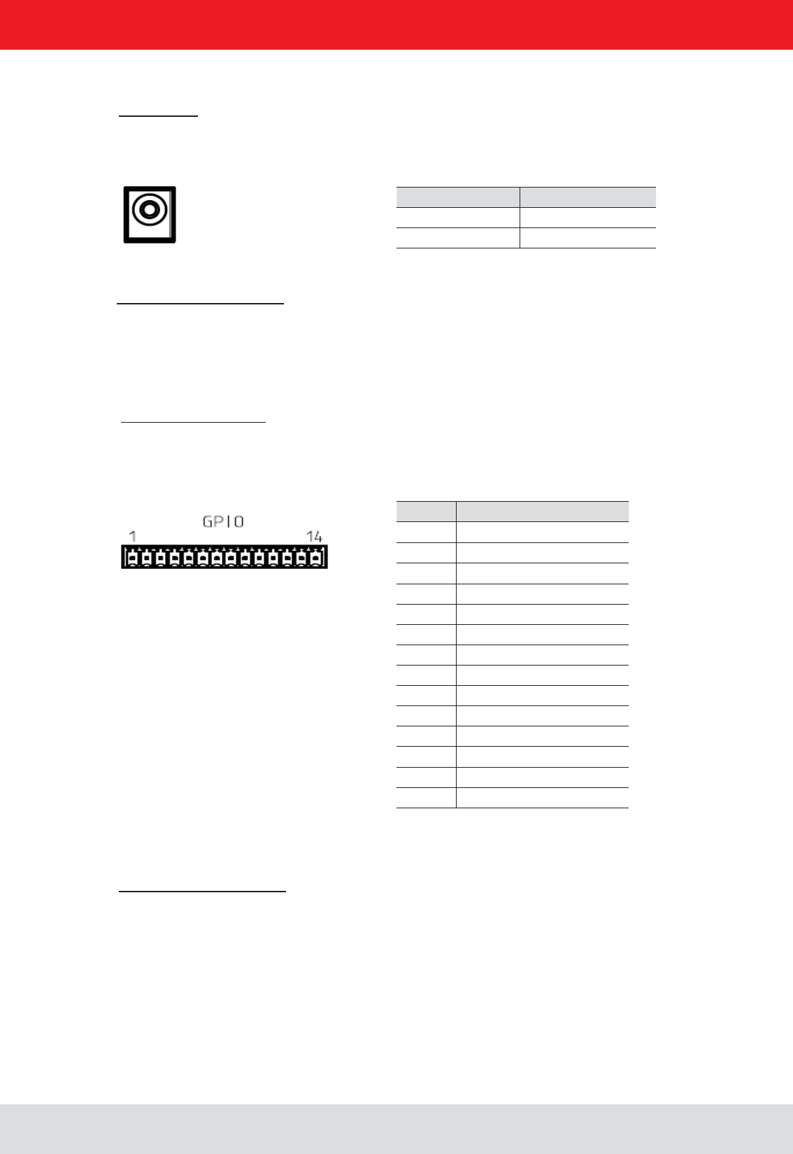
PIN Allocation
1 power supply +
2 Masse
3 INPUT_0
4 INPUT_1
5 INP_COMMON
6 INPUT_2
7 INPUT_3
8 power supply +
9 Masse
10 OUTPUT_0
11 OUTPUT_1
12 OUTPUT_COMMON
13 OUTPUT_2
14 OUTPUT_3
Power supply:
The power supply is designed as a hollow connector 2.5 mm.
Digital inputs and outputs:
The digital inputs and outputs are provided via a fourteen-pin terminal block. The control and evaluation are
provided by the internal software.
Port communication interface:
To communicate with the reader, the ERU Ethernet connection via a standard RJ45 connector can be used.
Alternatively, the reader can ERUs through a standard USB type. B port can be controlled.
4.6. RDR connection
Port communication interface:
To communicate with the RDR reader a Power over Ethernet (PoE) connection via a standard RJ45 connector is used.
PIN Allocation
inner conductor +24 V
outer conductor Masse
Installation manual Reader 23
English
4.7. M-ARU connection
4. Connections and displays
Supply voltage PoE:
PIN Allocation
1 GPIO – OUT3
2 GPIO – GND
3 GND
4 RS 232 – GND
5 RS 232 – RxD (mit TxD vom PC verbinden)
6 RS 232 – TxD (mit TxD vom PC verbinden)
7 + 24 V DC
8 GPIO – OUT2
9 GPIO – IN3
10 GPIO – OUT1
11 GPIO – IN2
12 GPIO – IN1
Supply voltage local GPIO/RS232/Ub
PIN Belegung
1 TD+
2 RD+
3 TD-
4 RD-
1 2
4 3

Installation manual Reader 24
English4. Connections and displays
4.8. UART transmission (RS232, RS422, RS485 or similar)
4.8.1. Bit transmission layer (physical layer)
A full or half-duplex connection such as RS232, RS422 or RS485 is used for the physical layer.
4.8.2. Data link layer
Transmission is in frames and blocks. A block comprises a maximum of 256 frames. A frame comprises a
maximum of 256 bytes, of which a maximum of 250 bytes can be user data. The result is a maximum block size of
64000 bytes of user data.
The data link layer is used to safeguard the data between sender and recipient. The sender receives a response
from the recipient for each frame received. If the sender does not receive a response from the recipient within a
time window of 350 milliseconds after sending a frame, the frame sent is repeated until the error counter signals
the cancellation of the transmission.
4.8.2.1. Structure of a frame
5A LL SS FF DD ... DD P1 P2
5A: Start code for synchronisation
LL: Number of bytes in the frame not including the start code
SS: Status byte
FF: Frame number
DD: User data
P1: 16-bit checksum low byte
P2: 16-bit checksum high byte
4.8.2.2. Start code and synchronisation
The start code is used to synchronise the recipient to the sender. It further allows the receiver to synchronise to the
start of a frame when no data have been received for 15 milliseconds.
4.8.2.3. Status byte
50: Data packet
A0: Response: “OK”
A1: Response: “Memory error” (the receiver was unable to allocate any memory for the data block received)
A response is only 3 bytes long and is not CRC checked.
“OK” response: 5A 02 A0
“Memory error” response: 5A 02 A1
4. Connections and displays

Installation manual Reader 25
English
4. Connections and displays
4.8.2.4. Frame number
can be shorter than 256 bytes. Each additional frame must have a length of 256 bytes (length byte LL is FF).
For example:
A block with 700 bytes of user data is to be transmitted. For this purpose the block is divided into three frames.
1. frame: 5A CD 50 02 – there now follow 200 bytes of user data – P1 P2
2. frame: 5A FF 50 01 – there now follow 250 bytes of user data – P1 P2
3. frame: 5A FF 50 00 – there now follow 250 bytes of user data – P1 P2
(block size = frame number * 250 bytes + length byte -5) (here in the example: 2 * 250 bytes + 205 bytes - 5 bytes =
700 bytes), and reserve an appropriate amount of memory for the data.
4.8.2.5. User data
4.8.2.6. Checksum
The checksum is calculated using the polynomial x^16 + x^12 + x^5 + 1 with a pre-initialisation of 0x0000 from the
start code to the last user data byte.
4.8.3. Network layer
As the KBRP is a point-to-point protocol, there is no network layer.
4.8.4. Transport layer, session layer, presentation layer
Do not exist.
4.8.5. Application layer
The application layer transmits data blocks from 1 to a maximum of 64000 bytes.
4. Connections and displays

Installation manual Reader 26
English4. Connections and displays
4.9. LLRP-Protocol
Note
Based on the communication protocol TCP, the Kathrein RFID reader with the Linux
operating system can handle the so called Low Level Reader Protocol (LLRP).
This is a by EPCglobal (http://www.epcglobalinc.org/standards/llrp) standardized com-
munication interface between RFID reader and a LLRP-enabled application software.
The default port for LLRP is 5084.
This LLRP protocol is roughly divided into the following parts:
software
To start the LLRP application, please use the AppManager of the ReaderStart Sw.
App“.
To test the Kathrein reader with the LLRP protocol you can use the open-source pro-
be controlled and operated.
Installation manual Reader 27
English
4. Connections and displays
4.11. Digital inputs and outputs
4.10.1. Frame structure
A frame is structured as follows:
Start + Data block + End
4.10.2. Port
The TCP communication port is the Port 4007.
4.10.3. Example
As an example the frame for “ASyncGetEPCs” is shown. The ID for this command is the “0x0111” which then causes
the frame to appear as follows:
0xAA 0xBB 0x01 0x01 0x11 0x01 0xAA 0xCC
4.10. Ethernet transmission
When communication to our reader is via Ethernet, a data transmission layer is also used, as for serial communication.
The transmission layer via Ethernet looks much simpler here, because the TCP/IP protocol already provides a
data security layer. All we need to add are the packet start and packet end, since TCP/IP is a streaming protocol.
The activation and evaluation can be performed using the software ReaderStart v2, with the DLL supplied, or by
access to the reader protocol.
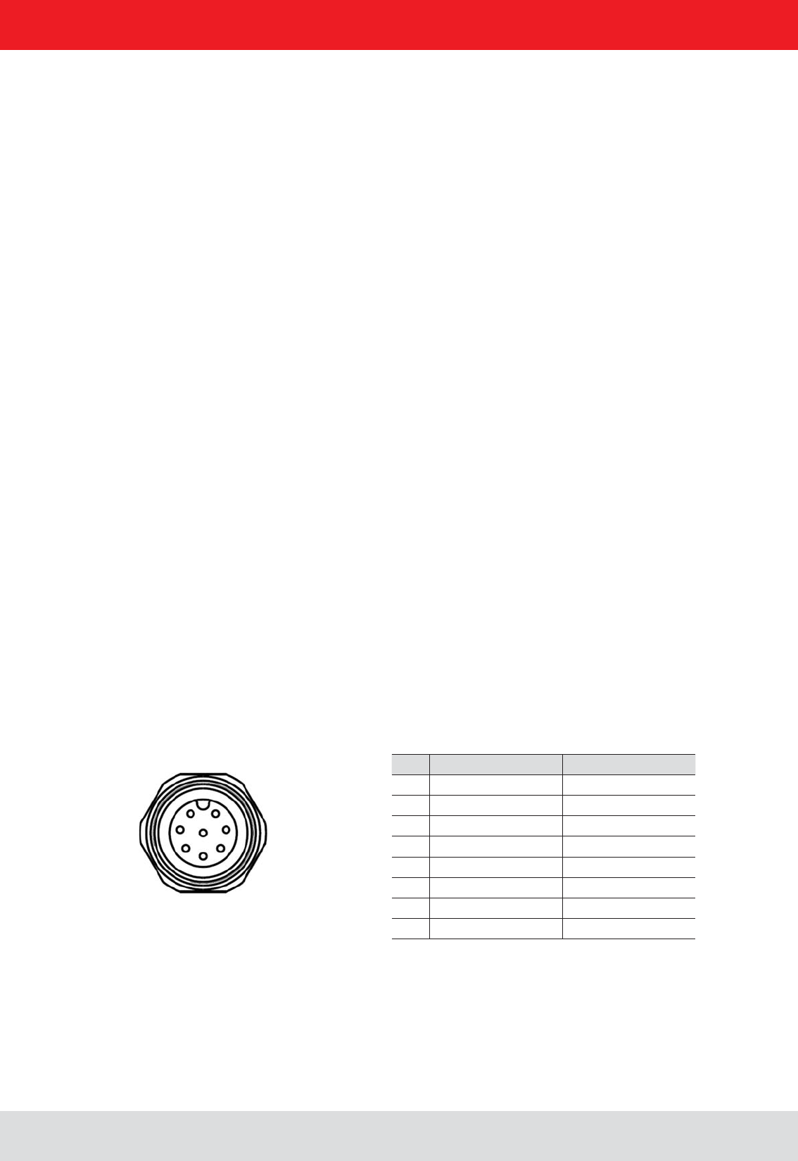
Pin GPIO 1 GPIO 2
1 OUT_CMN OUT_CMN
2 INPUT 4 INPUT 1
3 INP_CMN INP_CMN
4 GND GND
5UB UB
6 OUTPUT 4 OUTPUT 2
7 OUTPUT 3 OUTPUT 1
8 INPUT 3 INPUT 2
1 2
7 3
6 4
5
8 central pin
Installation manual Reader 28
English
4. Connections and displays
Allocation of the GPIO interface cable (Order-No. 52010125, 52010126)
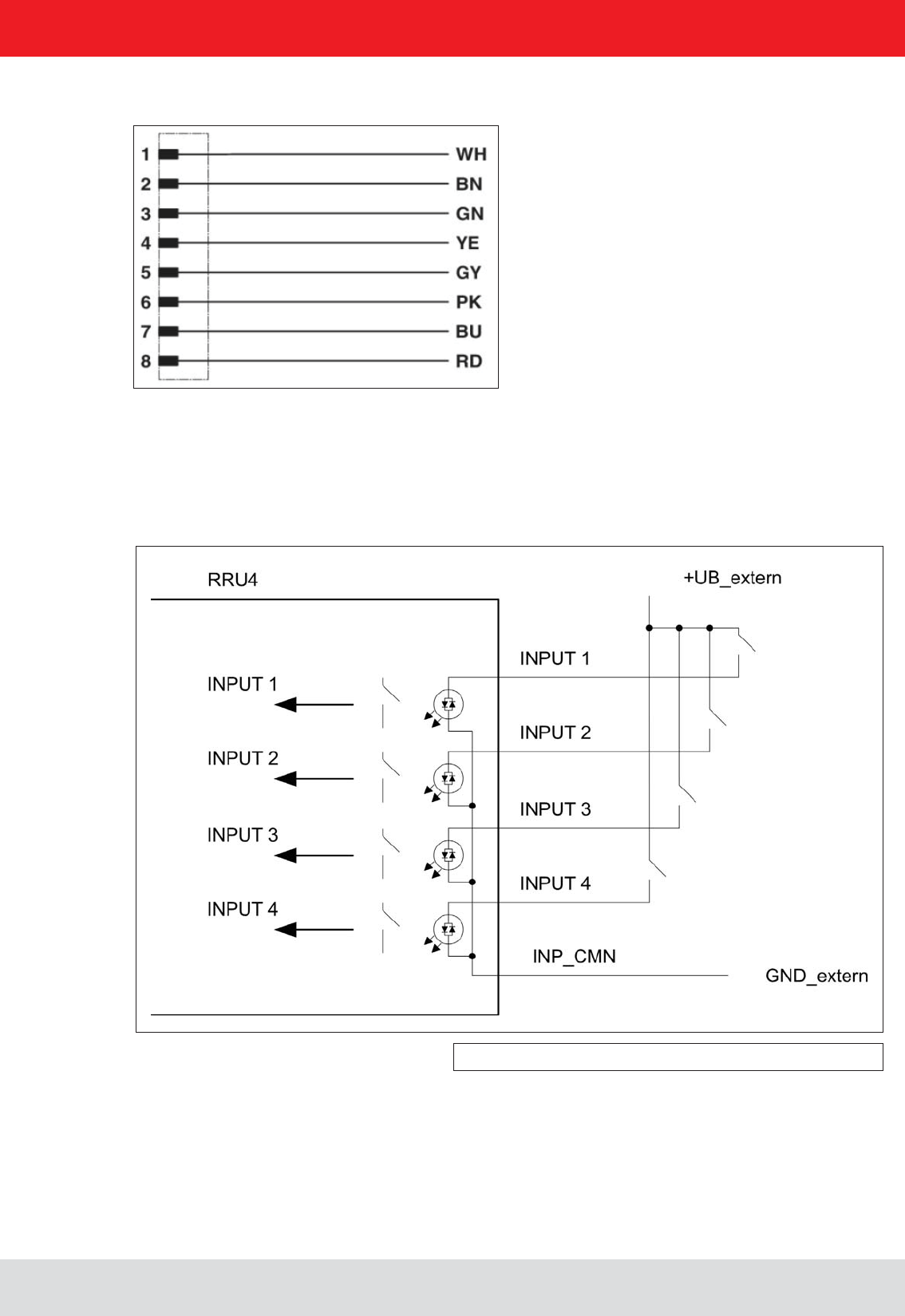
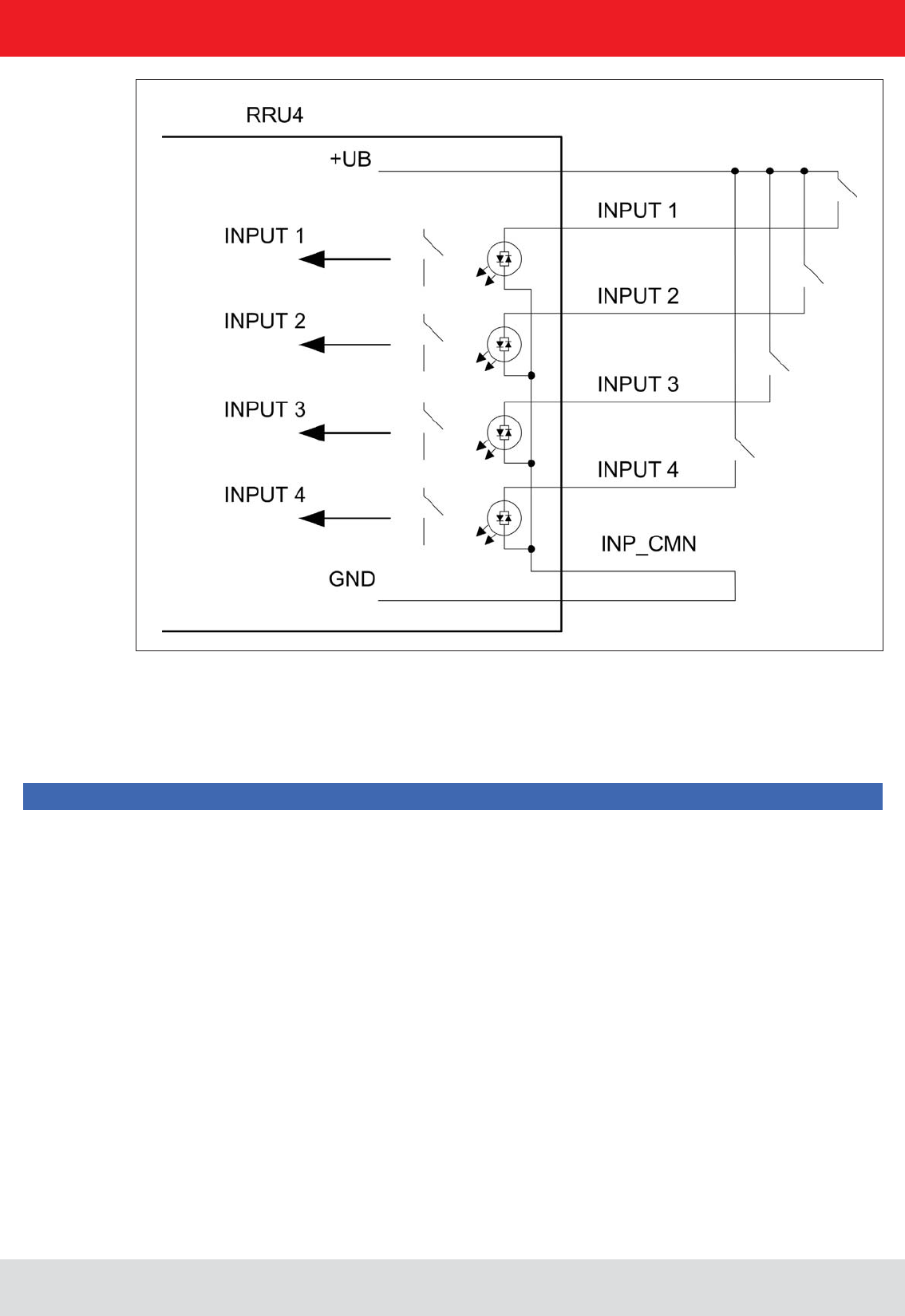
The digital inputs and outputs are communicated via two eight-pin sockets in A-coding with M12 connection
threads. The inputs are double isolated from the power supply of the reader and can be operated irrespective of
the polarity of the input signal. For this reason there is a common pin for the inputs (INP_CMN). The connection
variants for the inputs are shown below. Depending on the application, the power to the inputs can be double insulated
from the external power supply to the reader, or not double insulated from it.
Figure: Inputs double insulated
Installation manual Reader 29
English
4. Connections and displays
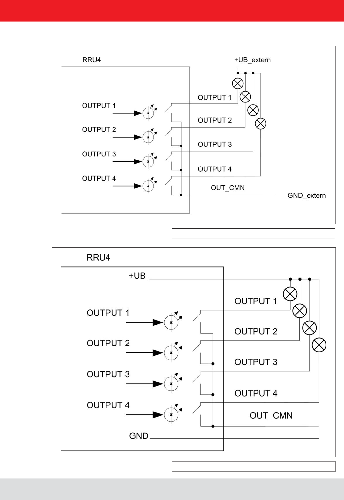
The outputs are also double insulated from the power supply to the reader and have a common pin (OUT_CMN).
If the double insulation is not required, the power supply can also be taken directly from the reader.
Please note that the load per channel is limited to a maximum of 0.5 A, and the total load across all the channels
must not exceed 1.5 A. The inputs and outputs are designed for a maximum voltage of 30 V DC. Further information
can be found in the data sheet for the reader.
Note
Installation manual Reader 30
English
4. Connections and displays
The connection examples for the outputs are shown in the next illustrations.
Figure: Outputs double insulated
Figure: Outputs not double insulated

Installation manual Reader 31
English
4. Connections and displays
4.12. Antenna Connection
4.13. LED
4.14. Buzzer
For the connection to the RFID antennas, the reader has four antenna connections that are of reverse
TNC design. Please only use the cable from the accessories or equivalent cable for this connection.
Note
Please only use cable suitable for the impedance (50 Ohm), as otherwise the performance of the reader will be
The reader has a 2-colour LED for the indication of the operating state. The table below shows the colours used
and the related operating state.
Red Green Operating state
X Error during initialisation
X X Unit is booting
Flashes approx. every 8 seconds X Normal operation with heartbeat
The reader has also ARU4 the antenna dome 4 LEDs. (Red / green / red / green) that can be controlled via software
Table: Indication of the operating states by the LED
(1 x short) or an error (2 x long).
Installation manual Reader 32
English
5. Software
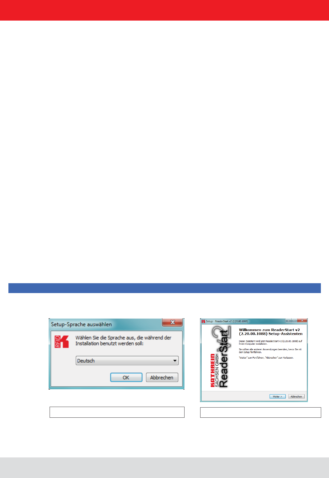
Figure: Installation Language
The splash screen is now appearing again information
about the exact state of the versionReader Start software.
This information can later be retrieved via the drop-down
menu in the menu bar info.
Figure: Welcome screen with software version
The presentation of the setup window depends on the operating system.
The following pictures show the state to install with software version 2.20. All subsequent versions are also installed.
Please follow the instructions on the screen.
For test purposes the reader can be operated using the demo software supplied. This software provides all the
settings for application scenarios are provided.
As well as this documentation, the following documents and programs can be found on the CD supplied:
- data sheet for the reader
- catalogue of the RFID products currently available
programming examples
- set-up program for the Kathrein reader start demo
- .Net Framework 4
- C++ 2008 redistributable
5.1. System requirements
To ensure correct operation using the software on your PC/laptop, your PC/laptop should meet the following
minimum requirements:
Processor: X86 compatible
Memory: 512 MB RAM
Operating system: Windows XP (SP3), Vista (SP1), Windows 7 or higher
free hard disk memory for:
32-bit operating system 850 MB (including Microsoft .Net Framework 4)
64-bit operating system 2 GB (including Microsoft .Net Framework 4)
5.2. Installation
The demo software is installed by running from the CD-ROM supplied. During
means that a check is made whether all the dependencies such as the necessary Windows Service Packs, the
.NET Framework in the respective version together with the C++ redistributables are installed. If this is the case,
during this process the demo software and the DLL for controlling the reader are installed.
After the start of the set-up, you can change the language used during the installation in the window that now opens.
button.
Note
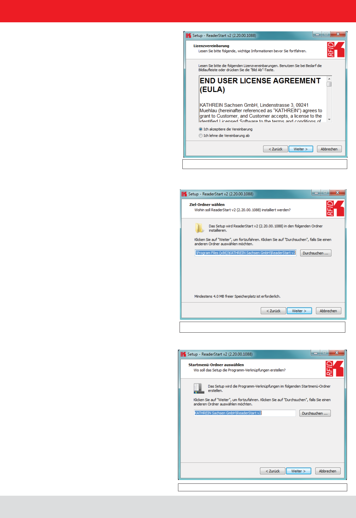
Clicking on the Next button takes you to the license
agreement. Please read this through carefully; if you do
not accept the terms of the agreement you must
decline to accept it. The installation is then terminated
at this point.
Installation manual Reader 33
English
5. Software
Figure: Selection of the installation folder
Figure: Selection of the folder in the start menu
In the next screen you can customise the folder in the Windows start menu. Here, as in the previous windows,
you are offered the standard settings.
If you have accepted the license agreement, press the Next button, following which you can select the target folder in
Installation manual Reader 34
English
5. Software
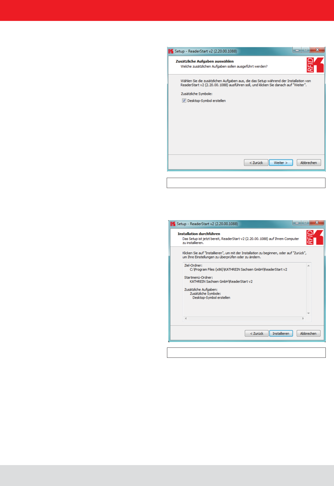
Figure: Selecting installation tasks
Figure: Summary of the installation tasks
In the following window you can specify whether you wish an icon to be included in the Windows Quick Launch
and/or on the Desktop. The default is to generate no icons.
Finally a summary of all the installation tasks is shown. Click on the button to start the
installation. If during the installation procedure a request is made to restart the computer, please do so.
Installation manual Reader 35
English
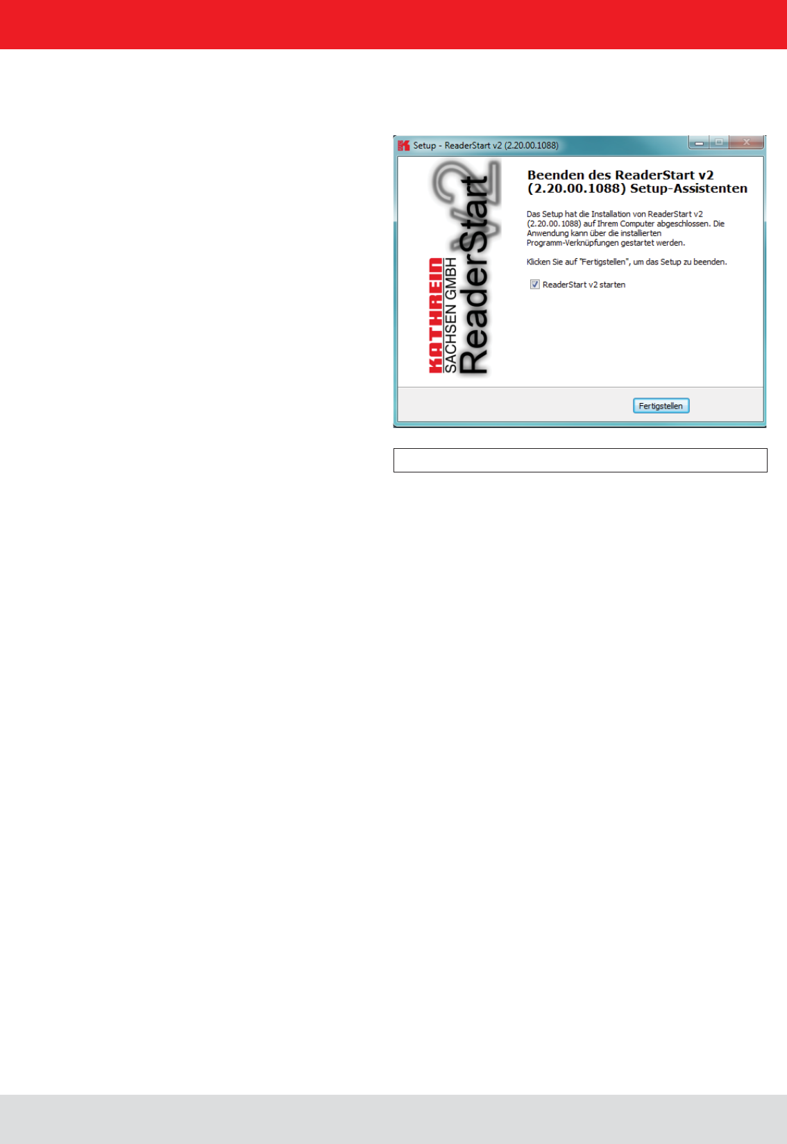
Successful completion of the installation is shown in the following window. If you do not wish to start using the
software straight away, please uncheck the , box, otherwise the program will start immediately
once you click on Finish
5. Software
Figure: Completing the installation
Installation manual Reader 36
English
5. Software
5.3.1. User interface for ReaderStart v2
5.3. Operation
In the following section, the Reader‘s launch software for the Kathrein RFID reader is described.
The program is started by ReaderStart v2.exe. The splash screen is displayed until all the necessary DLLs have
been loaded in the background. After this the user interface shown below appears. This consists essentially
Note
Functions that are unavailable are greyed out in the program.
The settings and controls for the reader are divided into individual functional groups under different tabs.
The individual sheets can be selected using the tabs. The sequence of the tabs can be changed as required by
“drag and drop”.
information itself.
Installation manual Reader 37
English
5. Software
5.3.3. Menu bar
The menu bar allows the program to be customised to your own requirements. These include for example:
options and info.
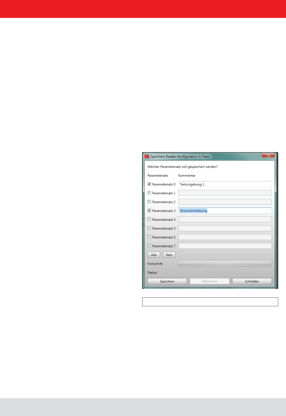
5.3.3.1. File
Under the item , a dialogue opens which displays all the available parameter sets
Selecting Save
have expired can be deleted in this menu.
sets are displayed. The assignment of them to the individual save locations can be reassigned here. For this purpose
the desired parameter set on the reader can be selected in the drop-down menu. Selection of the item None means
this parameter set is not loaded into the reader. In the default setting a 1:1 assignment applies. Pressing the Assign
parameter sets 1:1 button resets all the changes in the assignment to the default. Pressing the Delete assignment
button deletes all assignments of the saved parameter sets to those in the reader. In the drop-down menu this is
indicated by None.
Installation manual Reader 38
English
5. Software
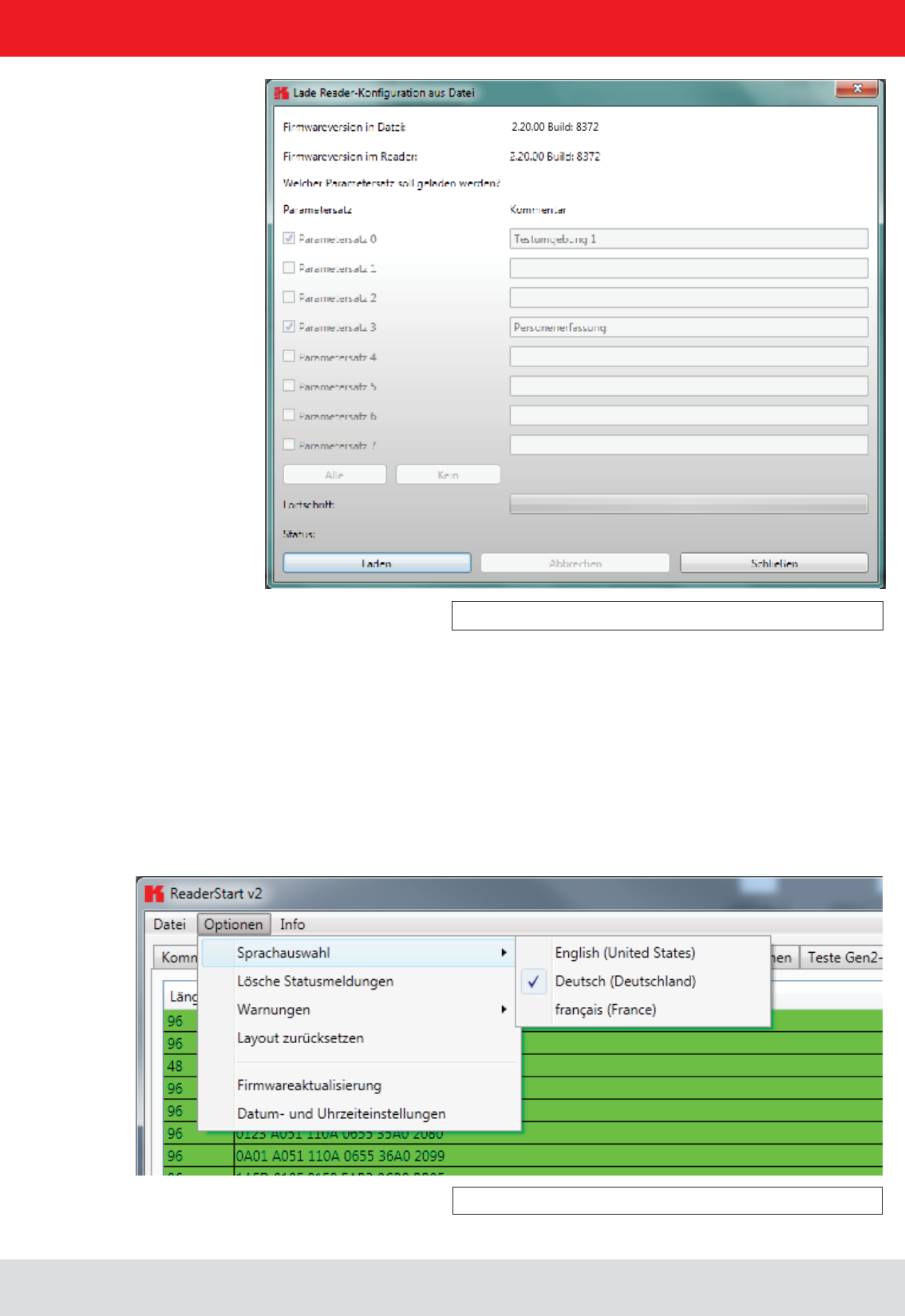
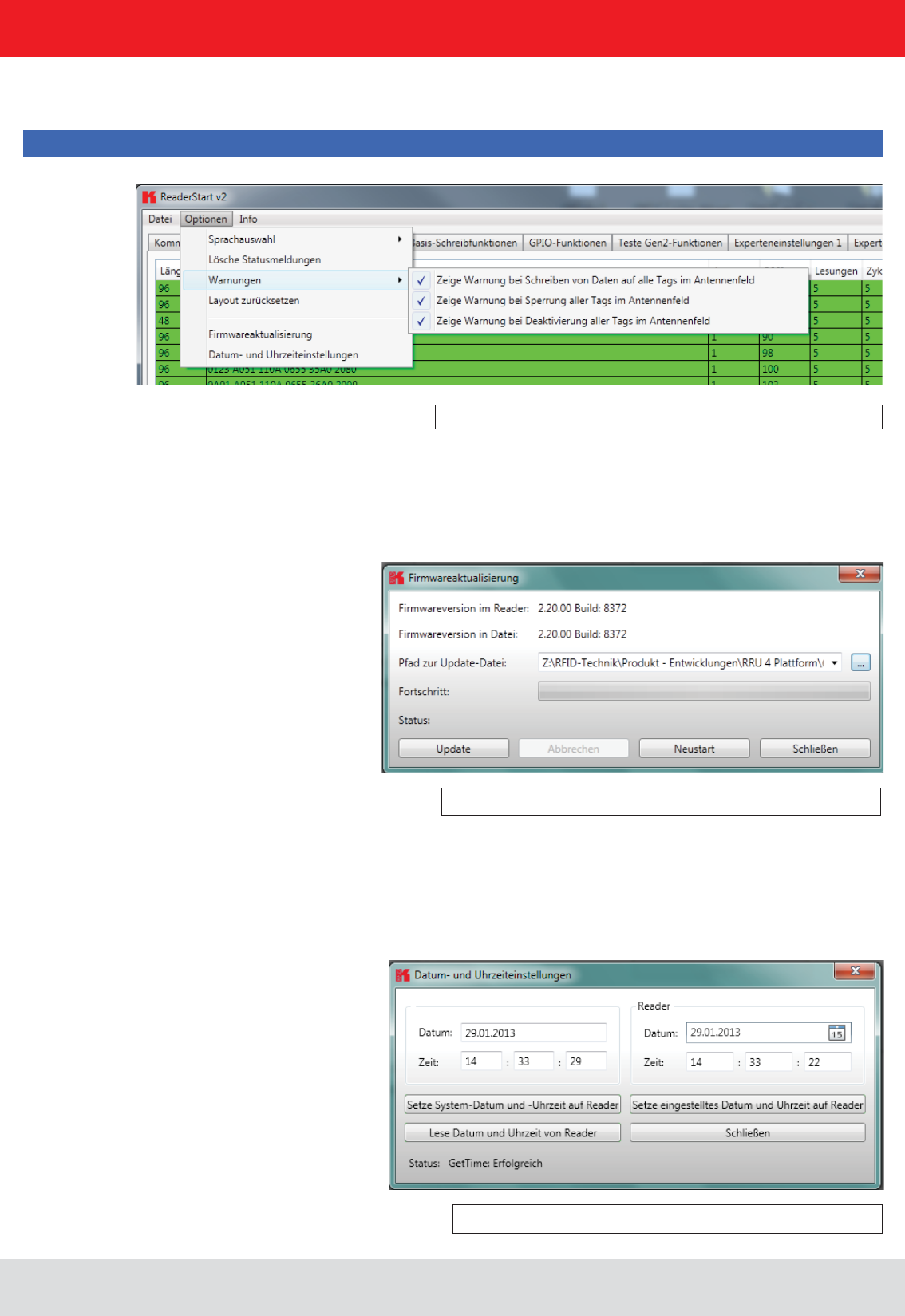
5.3.2.2. Options
Figure: Changing the language
The Options are divided into two groups. One part offers the facility to change or reset some properties
language by clicking on Language Selection in the menu item. The currently selected language is shown
by a check; if a computer restart is necessary in order to load the change, the program will indicate this.
Installation manual Reader 39
English
5. Software
Figure: Setting the warnings
Figure: Setting the date and time
Under the item Warnungen
Note
Changing the memory content of the tags can render them unusable.
If it is desired to recreate the original layout of the program in respect of window size and sequence
of tabs, this can be achieved by means of the Reset layout menu item.
Update button starts the procedure. The progress is shown in the Update progress line in a bar. After a successful
update the reader must be restarted, either by pressing the Restart button or by switching the power supply off and on
again.
The reader has an integral clock, which can deliver the time stamp for a tag operation. This clock is set using the Date and
time settings in the menu. When this menu item is opened, it automatically reads the current date and time from the reader
and compares this with the date and time from the host computer. The date and time of the host computer can now be
loaded to the reader by pressing the Set system date and time on Reader button. There is also the facility to set the reader
date and time manually and load it to the reader. This is done by entering the desired date and time on the reader side and
pressing the Set adjusted system date and time on Reader
and whether the action was successful.
Installation manual Reader 40
English
5. Software
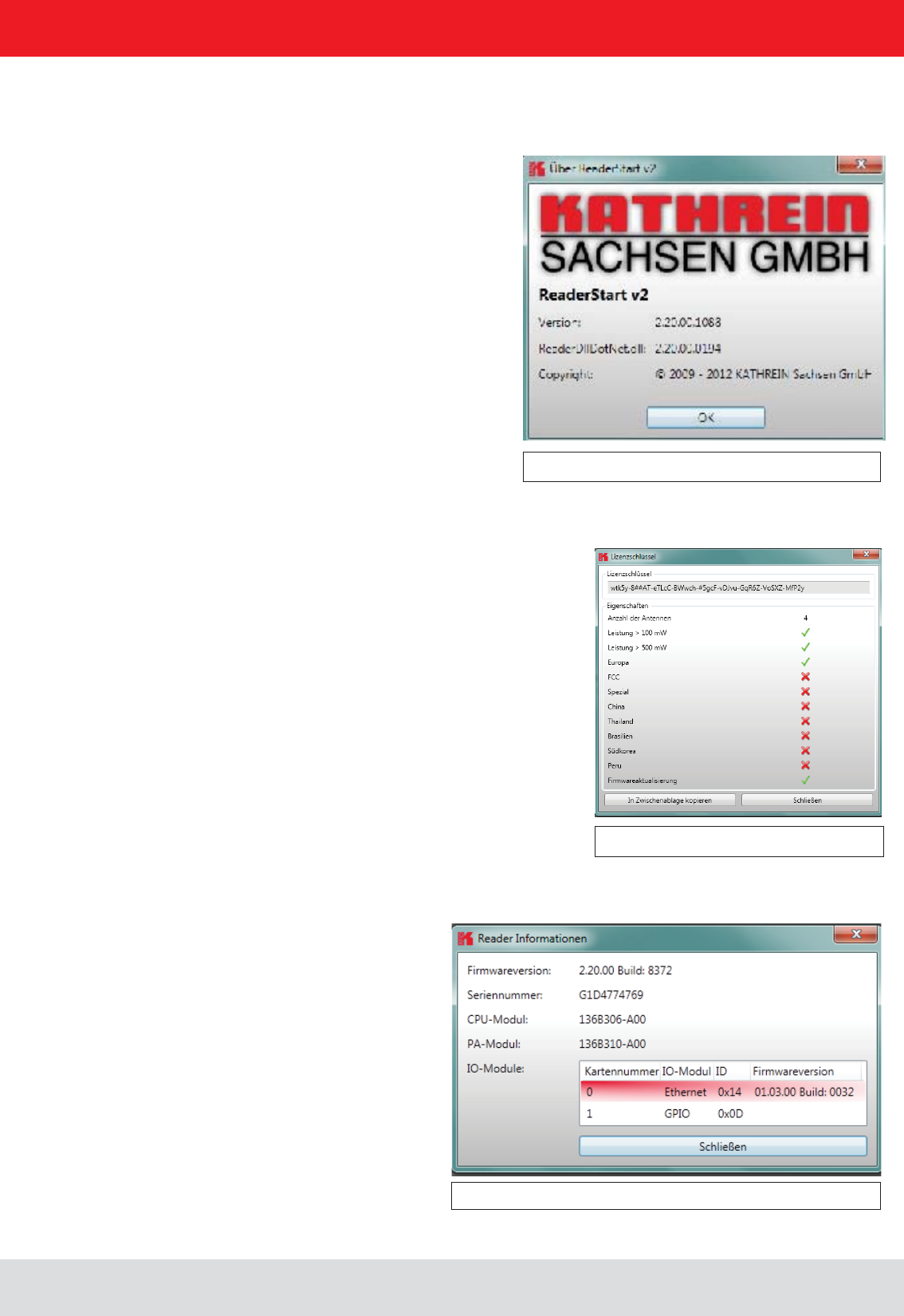
5.3.2.3. Info
Figure: About reader start v2
Figure: Displaying the license key
Figure: Interrogating information about the reader
This item on the menu bar allows information about the reader start software and the reader to be interrogated.
The second item automatically reads the license key. The key plays back various factory-set parameters of the reader.
key to be copied to the clipboard.
various I/O modules. The information about the I/O modules are stated in the format .
Installation manual Reader 41
English
6. Operating the reader
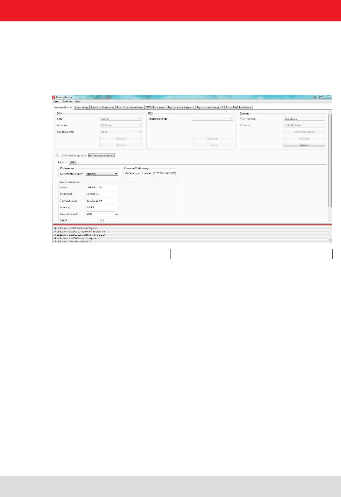
6.1. Communication
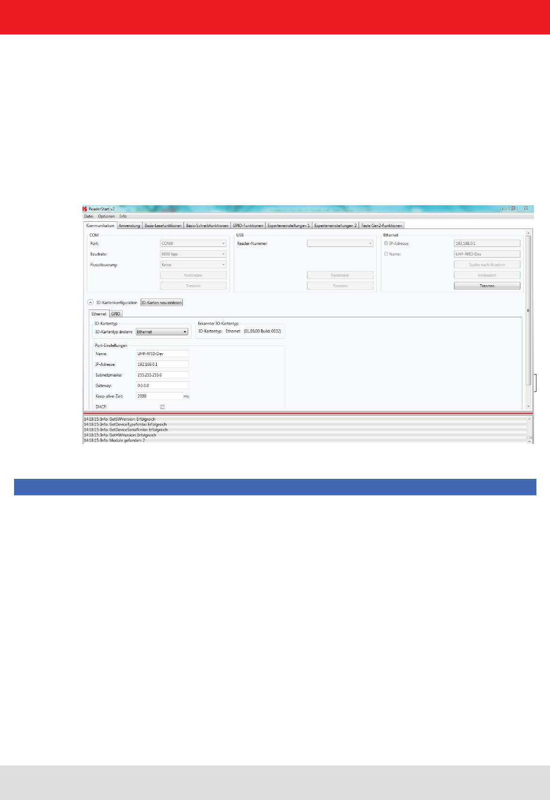
6.1.1. COM header
Figure: Tab for the Communication by Ethernet I/O card
interface cards. The various communication connections are grouped under 3 headers, COM for serial
connections via the COM port (RS232/485/422), USB for connections up to version USB 2.0 and Ethernet for
connections via TCP/IP.
When the connection is established, the program interrogates the information about the installed I/O cards. The
The serial interface is used for communication with the reader via RS232, RS485 and RS422.
The RS485/RS422 interface card supports the standard data rates of the serial interface on a PC. A level converter is
also required for communication to convert the RS232-compliant signal from the PC into a differential RS485/RS422
signal.
A serial COM port on the PC can be opened in this group box. For this purpose the correct serial interface must
be selected in the Port drop-down list box. Only the ports available on the PC are displayed in this list box.
It is not checked whether this port is already in use by other applications.
opened by clicking on the Connect button, which blocks it for other applications. If this port is already being
used by another application, a corresponding error message is output. If the port is free, the reader can be
operated using this port.
Pressing the Disconnect button breaks the connection and releases the interface again.
Installation manual Reader 42
English6. Operating the reader
6.1.3. Ethernet header
6.1.2. USB header
If a RRU4 is connected to the PC via USB, the unit is installed in the system as a USB HID-compliant device.
Correct logging in can be seen in the program if a reader number appears in the drop-down menu. This number is
unique for each reader. If several readers are connected to the PC, the related reader can be selected on this menu.
Clicking on Open now establishes the connection between the reader and PC.
The Ethernet connection can be achieved by linking the reader into an existing network, or by a direct connection
between the reader and a control computer. For direct connection of the reader to the PC, a cross-link cable
is required, unless the LAN interface on the PC supports “auto-mdi-x”. Alternatively two standard patch cables
and a switch can be used.
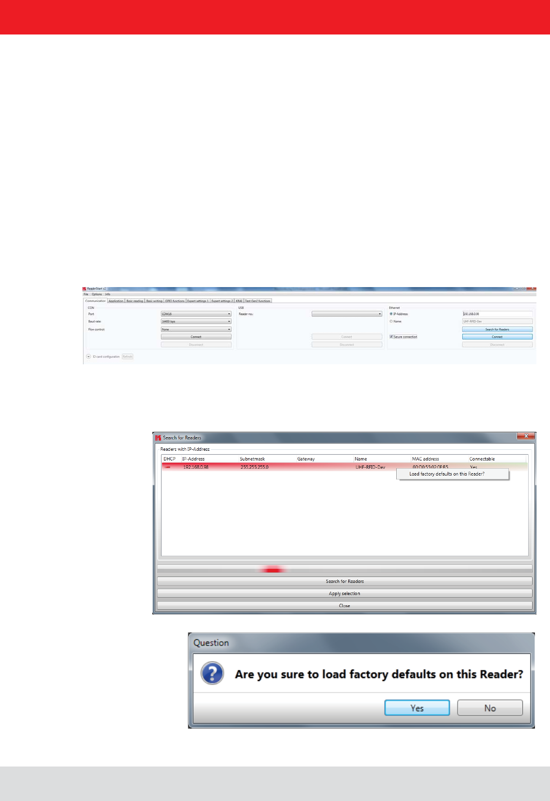
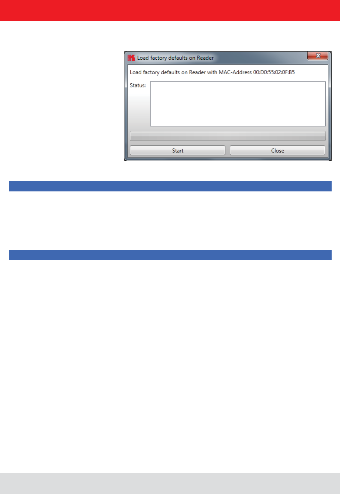
6.1.4. Reader to factory default via TCP/IP- broadcast cmd
To reset the reader to factory default, the ReaderStart SW will send out a TCP/IP- broadcast cmd. This is only possible
20 seconds after power rebooting. For this select at the folder “Communication”, press “Search for Reader”.
All reader in the network will be listed. Select the correct reader and press right mouse button.
Installation manual Reader 43
English
6. Operating the reader
Note
Note
The network mask on the other hand must be identical.
To integrate the reader into a corporate network, please contact your administrator who will be able to allocate
obtain an IP address automatically. For this service, referred to as DHCP, an appropriate DHCP server must be
In order to establish the connection to the reader, the program offers two options. On the one hand, it is possible
to communicate directly with the reader by entering the IP address, on the other hand it is also possible to
in the network. After power up, the reader makes a DHCP request and logs on to the DHCP server. This assigns
the reader an IP address and reports the network name and IP address to the DNS server. If now the connection
has been established, the IP address of the reader is determined by an enquiry on the DNS server.
The establishment of the connection is achieved if the establishment of the connection is selected under the
Ethernet header, meaning the selection of the IP address or name. For this, the correct IP address or the host
Connect button then opens the
data channel to the reader.
If you wish to establish a connection via an IP address, the
this address entered in it. The connection is established by clicking on the Connect button.
Installation manual Reader 44
English
6. Operating the reader
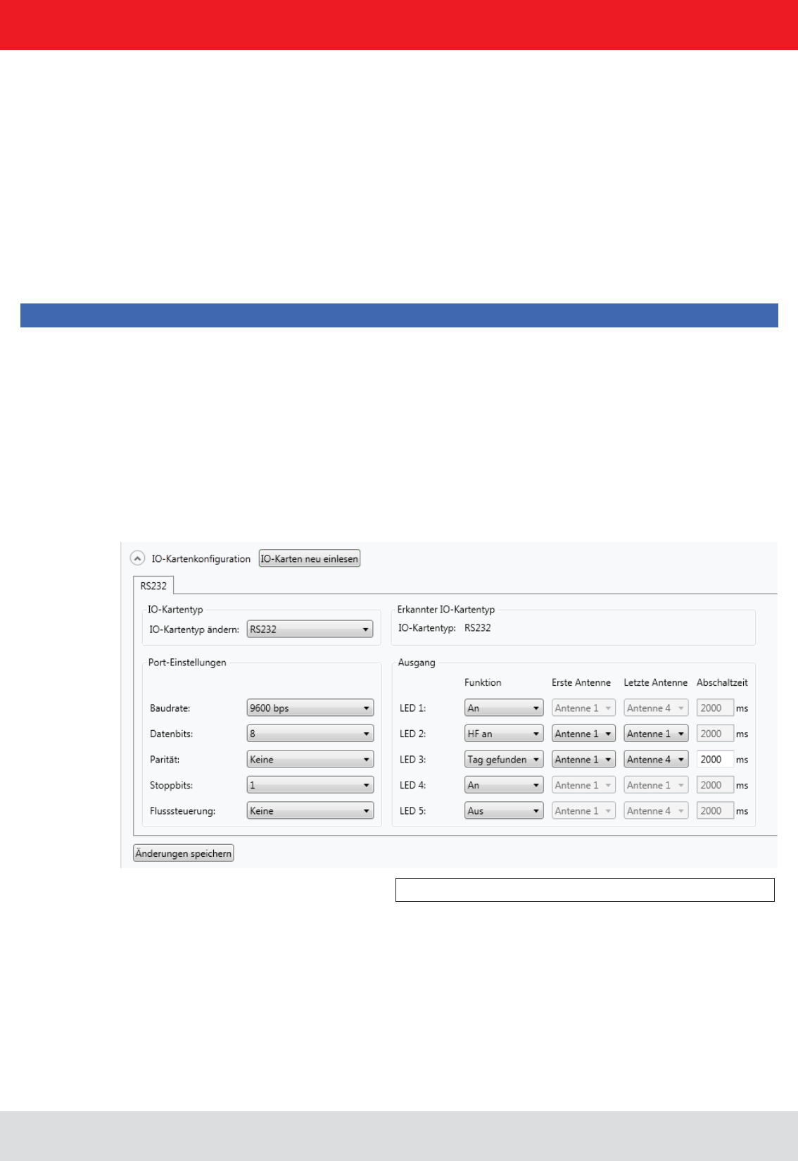
6.1.5.1. RS232
The communication interface settings can be changed using the . All available I/O cards are
displayed here in the form of tabs. Clicking on the respective tab opens the associated card and displays all respective
Under the header there is a drop-down menu, in which the card type can be set to Auto detect, Card not
used or to the actual card type. Automatic detection restores the interface to the default settings. What these settings
are is described in the following sections in relation to the interfaces. If the card type is set to not used, this interface
can no longer to used.
These parameters are described in the following sections for the respective card. The settings are saved to the
reader by pressing the Save changes button.
Note
Port settings and Output headers.

Installation manual Reader 45
English
6. Operating the reader
The communication parameters are grouped as follows:
1 Baud rate – the speed of the connection. All popular serial data rates up to 230,400 bps are supported
2 Data bits – the number of data bits transmitted per byte. The card supports 5 – 8 data bits.
3 Parity – a bit for security of the data transmission
If None is selected, this bit is not transmitted. For all other settings this bit is transmitted. The even or odd parity
checks whether the number of bits including the parity bit is even or odd. Based on this information the recipient
can determine whether a bit has been switched. Mark and space specify whether the parity bit should be
between the PC and reader should be by software None or by hardware wires (Hardware).
Note
Note that for a point-to-point connection, the setting of this parameter must be the same for both participants,
otherwise no connection can be established. RS232 readers, whose serial interface is performed
for these outputs can be found under the Output header.
Note
Not all reader hardware issues support this functionality. Please check the reader data sheet for information.

Installation manual Reader 46
English
6. Operating the reader
6.1.5.2. GPIO
If the LEDs are present (only for ARU), the LED channels can be assigned various functionalities under this heading.
Further parameters can be activated, depending on the function selected. The following functions are available:
1 Off – the selected LED is deactivated
2 On – the selected LED is always on
7 RF on – the LED lights up for Turn-off time milliseconds as soon as the radio frequency is
present at the antenna First antenna to .
8 Antenna error – the LED lights up for Turn-off time milliseconds as soon as an antenna error occurs at antenna
First antenna to .
9 Tag found – the LED lights up for Turn-off time milliseconds as soon as a tag is found at the antenna First antenna
to .
10 RF on – the LED lights up for Turn-off time milliseconds as soon as an operation on a tag was successful at the
antenna First antenna to .
11 Protocol access – the LED can be switched on and off directly via the protocol.
Baud rate: 9600
Data bits: 8
Parity: None
Stop bits: 1
Flow control: None
LEDs: Off
The GPIO card allows the reader to interact with its environment. In this tab, the inputs and outputs can be
and Output.
Note
Refer to the electrical characteristics of the inputs and outputs in the data sheet; if these characteristics are
exceeded the card and the reader may be damaged.

Installation manual Reader 47
English
6. Operating the reader
option negates the electrical
input signal and uses this status for processing in the reader. If the check is not set, the signal is used unchanged.
Depending on the sensor being used (mechanical or electrical switch), a debounce time in milliseconds can be assigned
to each channel.
The outputs from the card can be assigned various functions. Further parameters can be activated, depending on the
function selected. The following functions are available:
1 Off – the selected output is deactivated
2 On – the selected output is always on
7 RF on – the output is active for Turn-off time milliseconds as soon as the radio frequency is present at the antenna
First antenna to .
8 Antenna error – the output is active for Turn-off time milliseconds as soon as an antenna error occurs at antenna
First antenna to .
9 Tag found – the output is active for Turn-off time milliseconds as soon as a tag is found at the antenna
First antenna to .
10 RF on – the output is active for Turn-off time milliseconds as soon as an operation on a tag was successful at the
antenna First antenna to .
11 Protocol access – the output is released and can be activated with all KBRP commands for GPIO.
Note
GPIO functions section for more details on action lists.
Once all the settings have been performed, the changes are loaded to the reader by pressing the Save changes
button, and take effect immediately.
Note
Auto detect or to GPIO, the reader must be restarted so that the
card is correctly initialised.
Installation manual Reader 48
English
6. Operating the reader
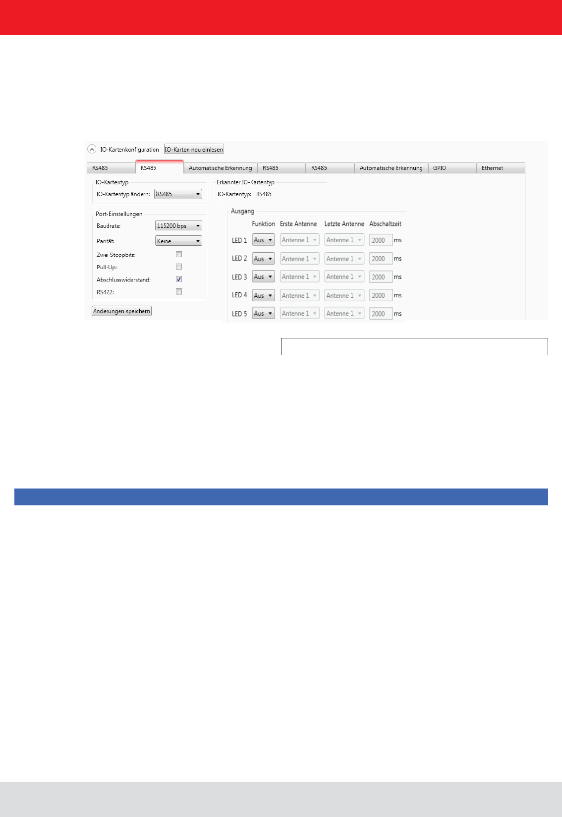
6.1.5.3. RS485
The LED control is only possible with ARU reader.
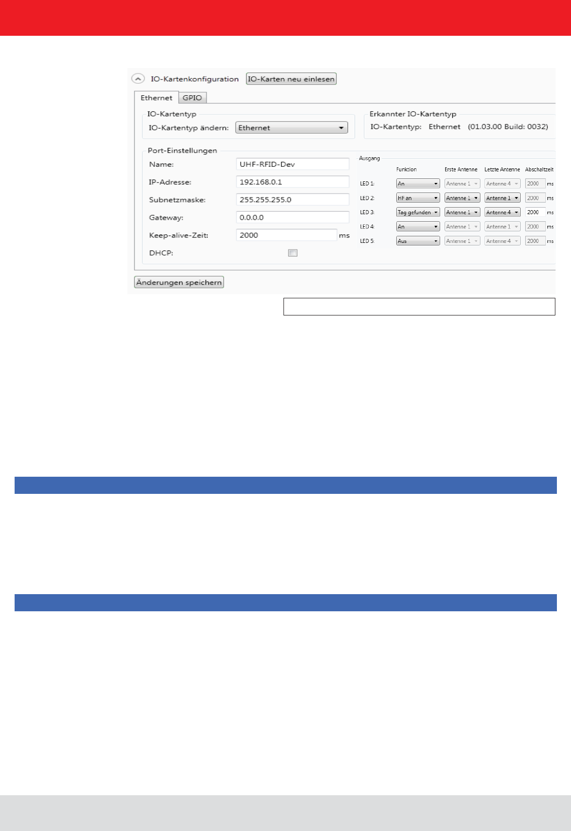
6.1.5.4. Ethernet
In order to establish a serial symmetrical connection to the EIA-485 standard, a RS485/RS422 card is required for
the reader. In addition to the parameters Baud rate, parity and stop bits, which are identical to RS232, the tab for
Port settings header.
The parameters have the following meaning:
potential (+5 V and GND). This procedure is recommended when the signal ratios between the communications
participants are critical.
2 Load resistor – terminates the differential wires against each other with 120 Ohm. This variant is required
when the reader forms the end point of the network.
3 RS422 – activates the RS422 mode of the interface card. This changes over the connection from 2-wire for
RS485 to 4-wire for RS422. This achieves a full duplex connection with differential RX and TX wires.
Note
Note that for a point-to-point connection or for connection of the participants in a network, the setting of this
parameter must be the same for both participants, otherwise no connection can be established.
Baud rate: 115200
Data bits: 8
Parity: None
Stop bits: 1
Load resistor: activated
RS422: deactivated
The parameters Name, , Subnetmask, and DHCP can be set for the Ethernet card on the
reader.
Installation manual Reader 49
English
6. Operating the reader
The settings for the LED display are visible only if ARU reader.
The parameters have the following functions:
1 Name – Here the host name of the reader which is logged on to the DNS server is stated. The reader can be
addressed by this name as an alternative to the IP address.
DNS server, the host name of the reader can also be used.
3 IP address – for manual issuing of the address. This parameter can be used only if the DHCP is deactivated
4 Subnet mask – for manual issuing of a network mask. This parameter can be used only if the DHCP is deactivated.
whether the receiver is still available. If the connection to the reader is broken, the reader shuts down the
connection. If this parameter is deactivated (0 ms), the socket is shut down only when the reader is restarted.
Note
reader and PC.
Note
data settings.
Host name: UHF-RFID-Dev
IP address: 192.168.0.1
Subnet mask: 255.255.255.0
Keep-alive time: 2000ms
DHCP: deactivated
The data are saved in the reader by pressing the Save changes button. The data are however not loaded to the working
Installation manual Reader 50
English
6. Operating the reader
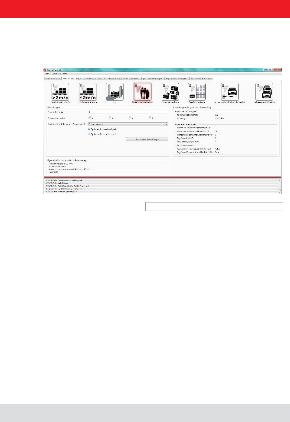
6.2. Application
Figure: Application tab
The Application
available applications are represented visually in the upper area of the tab by labelled pictograms. Under the Settings
saved and the values for max. read frequency and max. read reliability options are stated.
When the button for the desired application is clicked, it glows green continuously. In addition the designation,
The following applications are available for selection in version 2.00 of the ReaderStart v2:
o the distance between the tags and the antenna is only a few centimetres
at less than or equal to 2 m/s
o the distance between the tags and the antenna is only a few centimetres
o the distance between the tags and the antenna should be less than 1 m
than 14 m/s
o the distance between the tags and the antenna should be less than a few metres

Installation manual Reader 51
English
6. Operating the reader
Frequency of reading speed or reliability of reading.
several times, because all tags will be reset in the inventory, so that they will respond again. Because of reading the
be read.
The frequency of detection of the same tag is increased.
When this setting is chosen, tags already detected are not read again in the next inventory as long as the tag is
powered.
o the distance between the tags and the antenna should be less than a few metres
o the distance between the tags and the antenna should be less than 1 m
o the distance between the tags and the antenna should be less than 1 m
scrolling.
When the max. read frequency is set, for every detection (inventory) all tags are reset in order to read
so that some transponders are not detected. The frequency for detecting the tags should then be increased.
When the max. read reliability is set, tags that have already been read are not reset at every detection
(inventory), provided they are still being supplied with power. This means that only those tags which
Clicking on the Apply settings button saves the settings that were made, as well as the settings for the selected application,
Apply settings
and by display of a warning description or error description in the status window.
If the settings have been loaded successfully, a switch can now be made to the Basic reading tab and the read process
can be started.
Note
Installation manual Reader 52
English
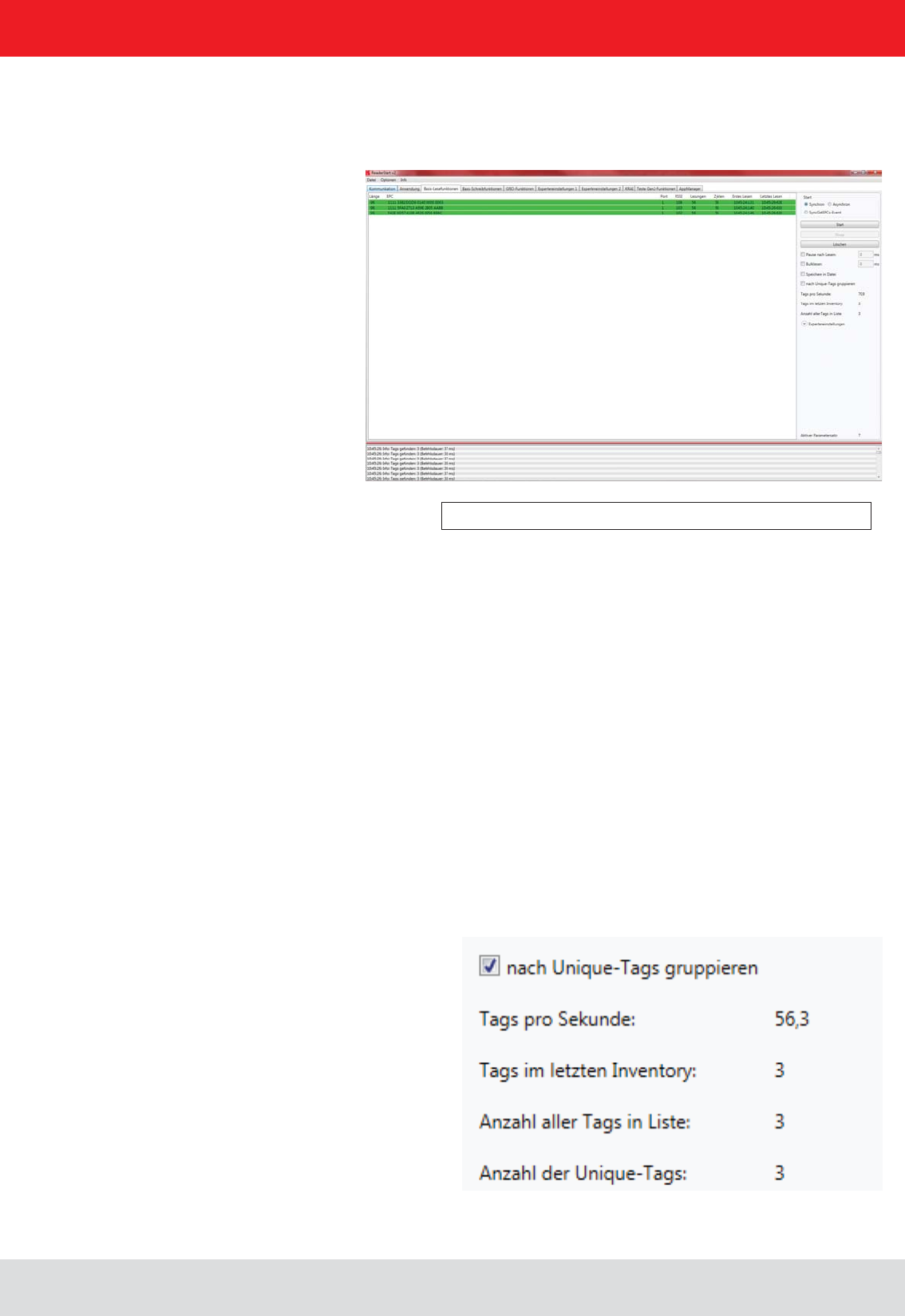
Figure: Basic read functions tab
6.3. Basic read functions
1 Length - indicates the length in bits of the EPC, valid lengths 0-496 bit
2 EPC - EPC of the tag in hexadecimal representation
3 Antenna - tag was read over this antenna post, valid values 1-4
4 RSSI - is the unitless (shown as having no units) signal strength of the tag response, valid values 0-255
5 Readings - shows how many times this tag has been read successfully
6 Cycles - indicates how often an inventory was started
7 Last reading - is the timestamp of the last reading of the Tag
The control of the reading process takes place in the second column of the index card. A distinction is made between
two modes is done on the following pages.
The second column can be sorted by the read result (unique) tags. This is especially useful in multi-antenna applica-
tions. For example, with a gate application with 4 antennas read per pallet with 100 tags, then the maximum number
of reading results will be 400. Since not all tags are read by all antennas, the reading results in general, will level off at
6. Operating the reader
Installation manual Reader 53
English
6. Operating the reader
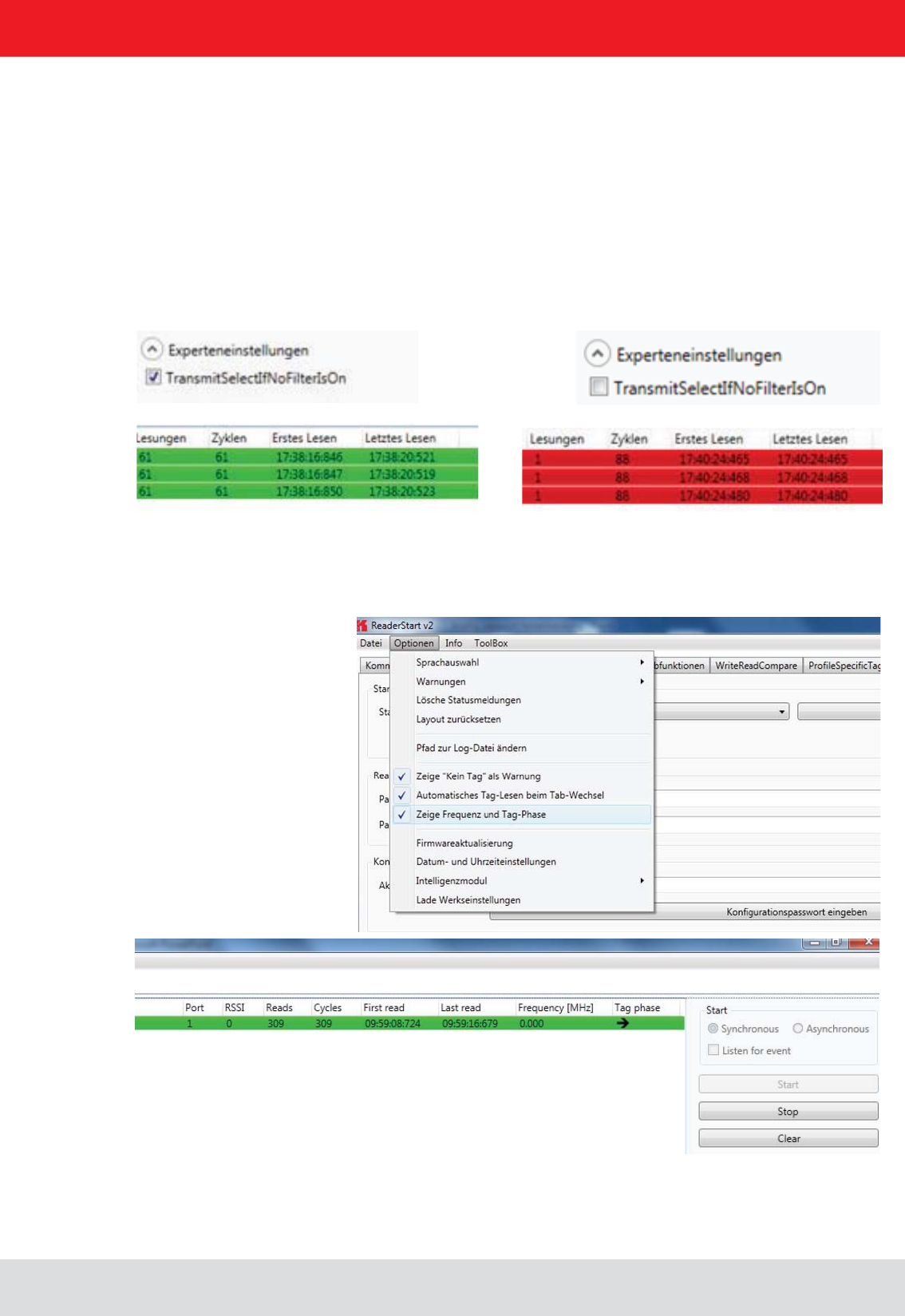
change to new "select command" (see EPC global standard (E)).
This can be tested by selecting "Expert Parameters" directly in read mode. If the read operation box is ticked with
again. In order to capture only new tags, a renewed "Select" can be prevented. This tick box is cleared on "Transmit
re-read. Please note, however, that tags in which the read operation was interrupted, they cannot be retrieved! Thus,
it may be that not 100% of the tags are read. Therefore, this parameter should be used with care in order to achieve
top results.
To display Tag phase and frequency during basic reading, the option “Show frequency and tag phase”
Should be selected in options menu.
6.3.1. Display Tag phase and frequency
With the change of the tag phase, a movement of the transponder can be detected.
-
lected

Installation manual Reader 54
English
6.3.2. Synchronous mode
6.3.3. Asynchronous mode
This mode is intended for applications when the requirements for timing are not so demanding. This mode allows
the facility to switch the carrier off during the idle times, thus saving power.
automatically retriggered by the PC.
The Pause after reading
about switching off the carrier.
In order to keep the time between inventories as short as possible in synchronous mode, data transmission between
the Bulk read parameter.
The current reading performance is displayed under the item Tags per second.
Note
option. The
the tag was read are saved.
for this item.
This mode is intended for applications for which maximum performance is required.
The reader starts the inventory as quickly as possible, and at the end of an inventory it does not deliver every tag
required for communication with the higher level to be minimised.
ObservedThresholdCnt and ObservedTimeoutCnt
Note
in the context menu for this item.
Once the mode and the parameters have been selected, the read process can be started. Both modes are stopped
by pressing the Stop button. The Delete button removes all tag entries from the table.
6. Operating the reader
Installation manual Reader 55
English
6. Operating the reader
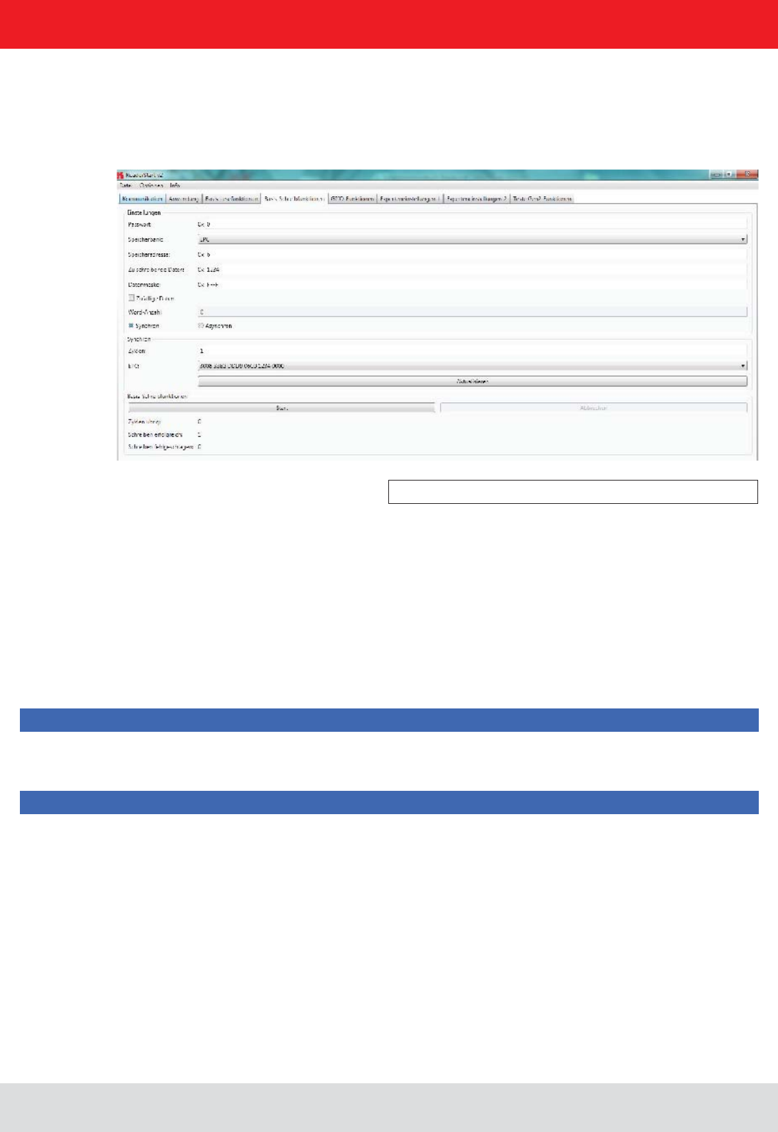
6.4. Basic writing function
Figure: Basic write function tab
6.4.1. Synchronous writing
The Basic writing tab allows input of basic descriptions of tags. A fundamental distinction is maintained between
synchronous writing - write on command - and asynchronous writing - write on arrival.
In this type of writing the data can only ever be written selectively to one EPC. This is selected in the EPC ComboBox.
Clicking on the Refresh
When all necessary data such as password, memory bank and memory address have been input a decision can
in words (16-bit).
Note
Right-clicking on the
Note
Right-clicking on the Data mask0 or F according to the number of the data
entered to be written.
Clicking on Start
completion of all write attempts is once again indicated by the button glowing green and by a message in the status
somewhat longer. The associated error message appears in the status window.
The Writing successful and Writing failed
mouse over the number of failed write attempts (provided indeed any failures did occur), calls up a window with detailed
information.

Installation manual Reader 56
English
6. Operating the reader
6.4.2. Asynchronous writing
(password, memory bank, memory address, data to be described - the input of the data mask is optional) have
been input, clicking on Start starts the asynchronous write process. Successful and failed write attempts are
any failures did occur), calls up a window with detailed information.
Note
Right-clicking on the Data mask0 or F according to the number of the data
entered to be written.
Installation manual Reader 57
English
6. Operating the reader
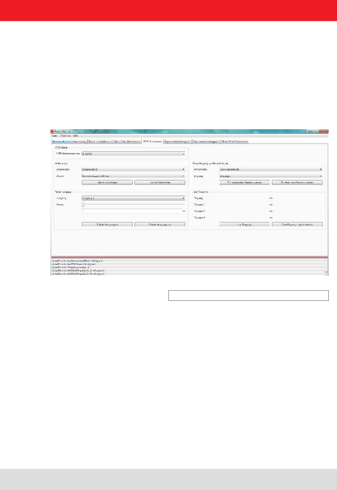
6.5. GPIO functions
Figure: GPIO functions tab
Readers with GPIO functionality offer the facility to set up small controls which trigger the reader for instance by a
The tab allows the user of the program the facility to load or switch inputs and outputs manually. For
more complex procedures, action lists can be created here, which execute a sequence of commands on the reader.
This list can then be linked to various inputs.
number must be selected in the GPIO card drop-down menu. This shows only cards of this type.
The Test output header can be used in order to selectively connect an output manually. In order to enable
this access, the respective output of this card must previously have been connected to protocol access (see
using the Duration parameter, until the output automatically returns to its idle mode. The connections can
now be made using the Set output on and Set output off buttons.
The inputs to the reader can be interrogated under the Read inputs header. Whether an input is set or
Read inputs
button. If this interrogation should be performed automatically, this process can be started by pressing
the Read inputs cyclic start button.
To automate the processes, command sequences in the form of action lists can be stored on the reader. These are
the context menu of the Action item under the Action list
a text editor. The syntax can be seen from the example. The individual actions can be selected from the
The action list must be selected from the drop-down list. The desired actions are now selected individually
from the action list and added to the action list in the sequence in which they are to be executed. Pressing the
Clear action list button clears down the selected list.

Installation manual Reader 58
English6. Operating the reader
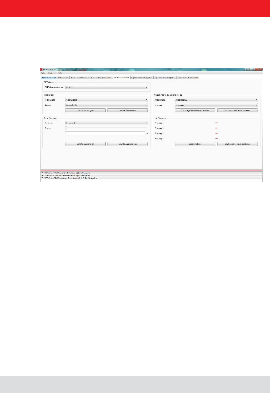
When the action list has been created, it is assigned under the Assign input to action list header to an input and a
The assignment can be cancelled again by a restart/reset of the reader or by assignment of the No action list
item.
deleted again.
For continuous operation of the reader, the commands for the digital inputs and outputs can be integrated into a soft-
ware application. This application software can be run on an external PC or on the industrial PC ETL and ELC reader.
Note

Installation manual Reader 59
English
In the same menu, the basic functions of the GPIO card can be set.
Here the global settings for the GPIOs are set.
Invertieren: when logically high level and high-level physica must be inverted
Debounce time depending on the switching element at the entrance
a directory where the system variables are stored. Here are inter alia the antenna list and the Action List for the inputs.
The approximately 150 reader commands with corresponding variance of the parameters do not allow for uniform list.
A selection of all options is extensive. Therefore it is recommended to only list required in the application instructions.
To the Action List (ActionlistAction.xml) can use an XML editor to edit.
The CommandIds can be found in the Reader Protocol ((A)).
After editing, the action list it in the reader startup directory under
6.5.1.3. Setting up a separate list ACTION
6.5.1. Example of GPIO function
6. Operating the reader
Installation manual Reader 60
English
6.5.1.4. Selecting commands from the ACTION list
available commands are listed.
the system banner with the message
6. Operating the reader
Installation manual Reader 61
English
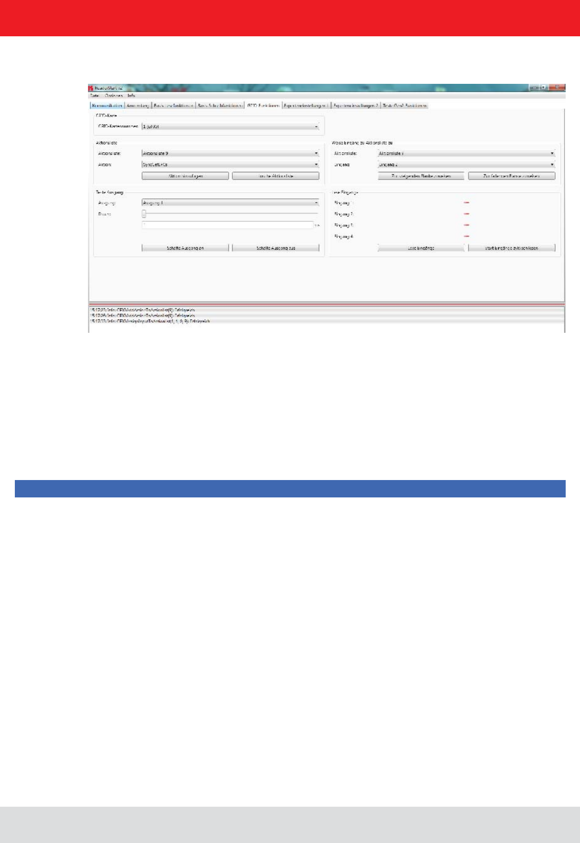
6.5.1.5. Assigning the ACTION list to the respective inputs
link to the inputs.
The action list (in this case 9) and the input (in this case 1) can be selected. Similarly, to determine whether to respond
to the rising or falling edge is.
Note
6. Operating the reader
Installation manual Reader 62
English
6. Operating the reader
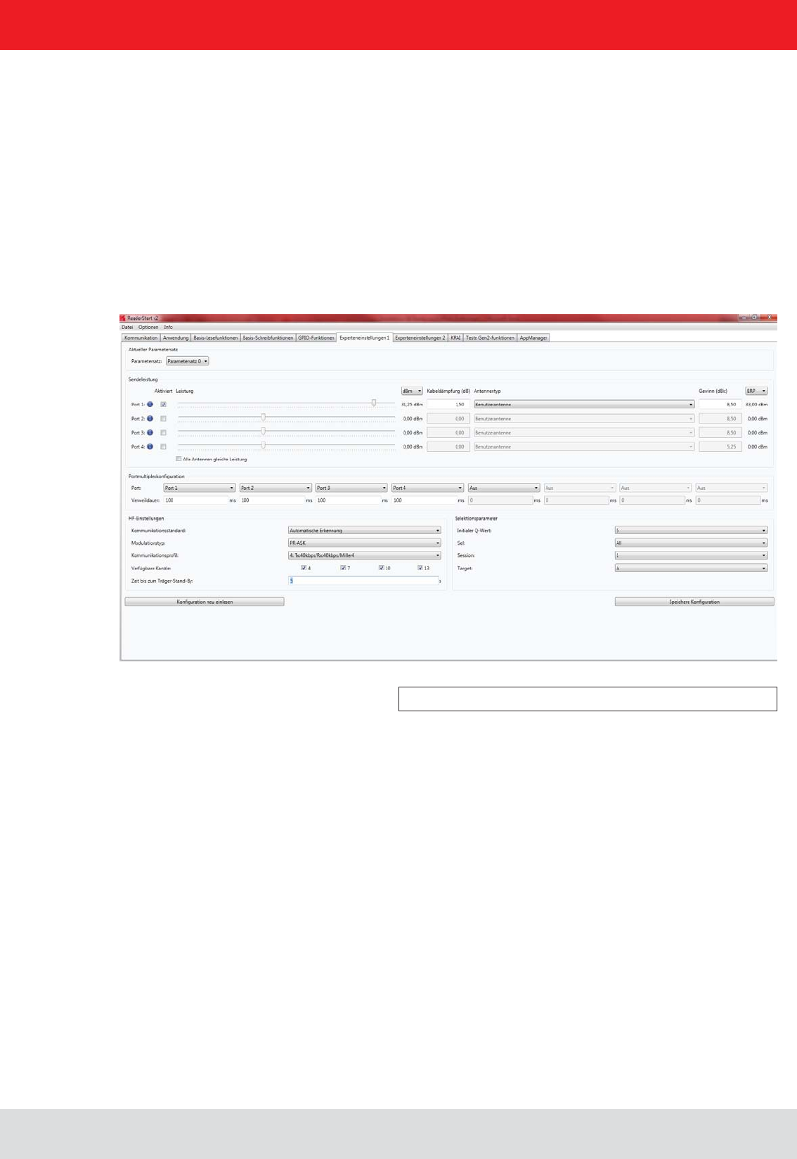
6.6.1. Expert settings 1
Figure: Expert settings 1 tab
The ReaderStart v2
be optimised to the tag so that the reader is optimally customised to the application.
memory slots. Other parameters can be changed in Expert settings 2
for more information about the individual parameters.

Installation manual Reader 63
English
6. Operating the reader
6.6.1.1. Transmission power
The cable attenuation is the length-dependent attenuation of the cable at the related frequency:
Pre-setting can be selected under the Current parameter set header. This is done by selecting a parameter set in
the drop-down menu. This parameter is now active and loaded, and the headers are updated. When all the desired
changes have been made, they can be saved. The changes to the settings can be discarded by pressing the Reload
button. The parameter set can be reloaded by pressing the .
Under the Transmission power header, the parameters of the transmission path can be entered; these include the
transmission power, transmission channel (only ETSI) and spectrum. The applicable standards in the related approval
region are to be observed when setting the transmission power.
Note
To operate the reader in accordance with the related national standards, the antenna gain and the cable
exceed the permitted transmission power. Failure to observe this instruction can result in non-compliant operation
of the reader rendering void the unit's type approval.
The radiated power is limited in Europe in accordance with ETSI 302208 to 2 W ERP. In the FCC / IC region, max. 1
W connected RF power applies with an antenna gain of 6 dBi. If the antenna gain is greater than 6 dBi, the RF power
must be reduced accordingly. While the European standard refers to a half-wave dipole, FCC part 15 / RSS 210 refers
to an isotropic radiator.
To set the transmission power, the length-dependent cable attenuation and the antenna gain must be included in
the calculation of the transmission power. An example for the calculation of the transmission power for Europe and
FCC / IC is given in the following.
The following applies to the European approval region:
PReader = PERP + DKabel – GHW
PReader...Transmission power of the reader in dBm
PERP
......Transmission power based on a half-wave dipole in dBm
DKabel.....Cable attenuation in dB
GHW......Antenna gain based on a half-wave dipole
The antenna gain is stated in various different units. These units include dBi and dBic. The units dBi and dBic refer
to an isotropic (spherical) radiator, where dBic refers to a circularly polarised isotropic radiator and dBi to a linearly
polarised isotropic radiator.
The relationship shown below exists between an isotropic radiator (dBi) and a half-wave dipole.
DKabel = l*DdB/m
DKabel....Cable attenuation in dB
l...........Length in m
DdB/m.....Attenuation in db/m at frequency

Installation manual Reader 64
English
6. Operating the reader
If the gain of the antenna is referred to the polarisation of a circular isotropic antenna (dBic), the linear gain of the
antenna is 3 dB lower. As a result the transmission power can be increased by 3 dB.
In the FCC / IC approval region, the RF power connected at the antenna input must not exceed 1 W. If the gain of the
power is then:
The transmission power for the European variant can be set in 0.25-dB steps from 20 dBm to 33 dBm.
Note
The antenna gain must be stated in dBic.
check box is set, the sliders for the other antennas are
not selected, the power at the antennas can be set separately for each output.
Antenna type selection drop-down menu. This selection sets
the antenna gain in the program, and limits the transmission power to the maximum value permitted for this
Custom antenna is selected, the gain and power can be freely set.
GHW = Gisot – 2.14dB
GHW....Gain based on a half-wave dipole
Gisot....Gain based on an isotropic radiator in dBi
GHW = Gisot – 2.14dB – 3dB
GHW....Gain based on a half-wave dipole
Gisot....Gain based on an isotropic radiator in dBic
PReader = Pcond + DKabel with PcondisotdB
PReader...Transmission power of the reader in dBm
Pcond......Power on antenna output in dBm
DKabel.....Cable attenuation in dBm
GHW......Antenna gain in dBi

Installation manual Reader 65
English
6. Operating the reader
6.6.1.3. RF settings
6.6.1.4. Selektionsparameter
The sequence in which the antennas are used to read the tag can be set under this header. If this antenna is not
activated, the system proceeds to the next entry on the multiplex list. For asynchronous operation of the reader,
sections and for more details.
Depending on the approval region, the reader transmits in the frequency range 865 MHz to 868 MHz for Europe or
902 MHz to 928 MHz for USA / Canada.
In Europe the number of channels to be used can be limited. For this purpose the related check box
for each channel the reader is to use must be selected on the Available channels list. In this manner
communications standard. The reader then starts to search through the channels in ascending order.
In the Communication standard drop-down menu, when necessary and when permitted by the reader, the reader can
standards that are permitted.
The modulation type can be switched between double sideband and PR-ASK modulation in this drop-down menu.
orientation on the transmission and reception data rates.
Note
further details.
interface after the last action. Once this time has elapsed the carrier is switched off.
can be selected in the drop-down menu, and have the following meanings:
)
capital 2.4.10. “)
capital 2.4.3. “Sessions”)
“)
Installation manual Reader 66
English
6. Operating the reader
6.6.2. Expert settings 2
Figure: Expert settings 2 tab
The Expert settings 2
parameter set can be changed, one parameter set copied into another,reader parameters read to determine their ID
The Default parameter set
RAM when the Kathrein RRU4 reader is started.
The Copy parameter set header allows one parameter set to be copied into another. On successful completion of the
copy operation, the Copy
otherwise the Copy button glows red.
The Change reader parameter header allows all the Kathrein RRU4 reader settings to be changed using their
of the Kathrein RRU4 reader is read by clicking on Get parameter value
optionally as a decimal (dec) or hexadecimal (hex) value. A value that has already been read can be converted to dec
or hex by pressing the radio button. The Set parameter value button writes the value stated in the Parameter value
the respective colour to indicate success and failure, and a message appears in the status window accordingly.
In the Select settings Select command. This
Installation manual Reader 67
English
6. Operating the reader
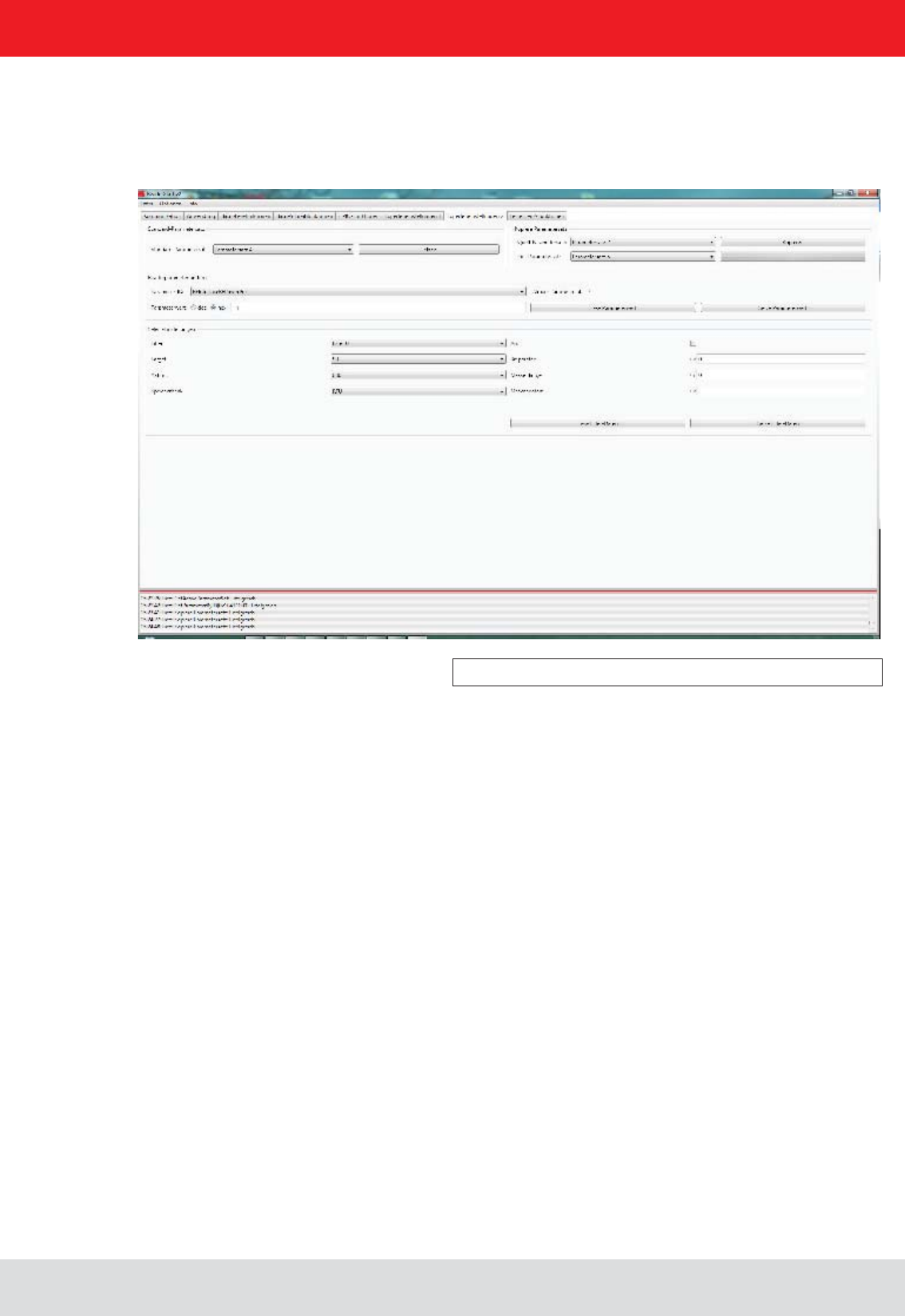
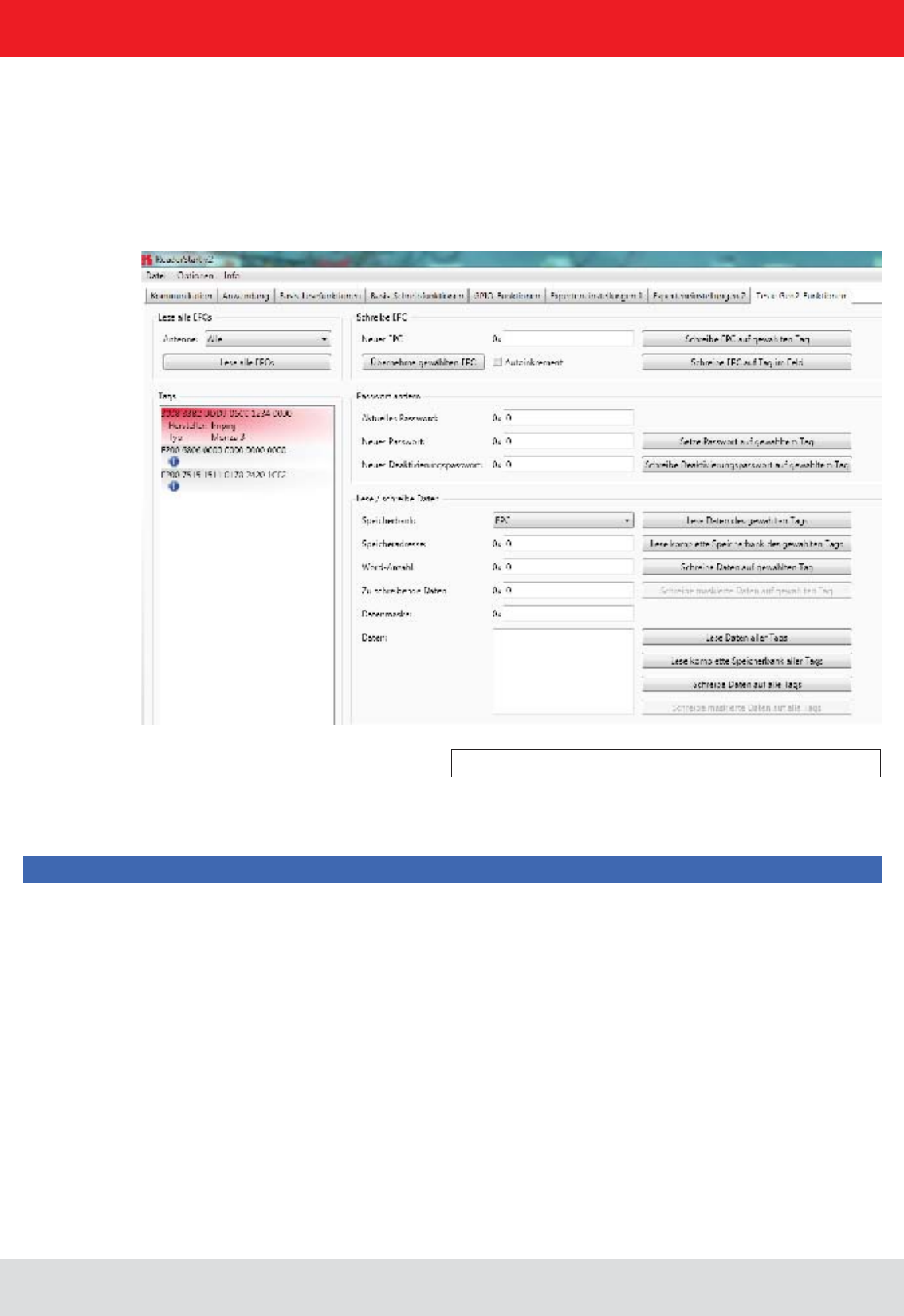
6.7. Test Gen2 functions
Figure: The Test Gen2 functions menu tab
this information can be retrieved.
This tab makes it possible to access individual functions of the reader. This includes, along with the functionality
in accordance with the EPC-Gen2 standard, e. g.: read individual tags, describe tags, set and change passwords,
and also select the antenna for the operation.
The user interface consists of the headers Get all EPCs, Write EPC, Change password, Read/write data, ,
and the display window for EPCs that have been read. The sections that follow explain this functionality in more detail.
Note

Installation manual Reader 68
English
6. Operating the reader
6.7.1. Get all EPCs
6.7.2. Write EPC
6.7.3. Change password
To read a tag in this menu, the Get all EPCs button must be clicked once the reader has been correctly
If in the Antenna selection drop-down menu the number of antennas has been restricted, reading will
now be performed using the currently selected antenna, or using the antenna selected with All in the
Expert settings 1.
selected from this list by clicking on it.
The EPC of the tag can be altered as desired under this header. For this purpose an EPC in hexadecimal format
must be entered in the New EPC
Note
Comply with the maximum EPC length supported by the tag - if this is exceeded the tag will return an error.
Apply selected
EPC button. Now the EPC can be changed manually, or by using the option can be increased by one
at each write event.
The write event itself can optionally be executed on this tag by pressing the button. At this
open and the secured state.
In the open state, operations can be performed on the tag if the associated memory areas are not secured with
a password greater than 0. If a password has been set and the header has been used to set the memory
areas to password protected, the desired operation will not be executed, and the tag will report an access error.
Normal access remains available in areas that are not blocked.
If when the tag is accessed the valid password is given, the tag switches into the secured state and access is available
even in blocked areas. Setting the password and setting how individual areas are blocked is performed under the
Change password and headers.
tag are set. The access password can be used to restrict access to the tag in the open state. Depending on the
header, parts of the tag can be provided with completely or partially restricted access
rights.
The deactivation password is required to deactivate the tag permanently by means of a Kill command.
Note
After a Kill tag command, the tag will be unusable.
Clicking on the button replaces the old password with the new password.
to the new password the access password must be entered in the

Installation manual Reader 69
English
6.7.4. Read/write data
6. Operating the reader
6.7.5. Lock
This header supplies detailed access to all the data areas of the tag. Access is obtained by entering the selected
memory bank, the address within the memory bank and the number of words, expressed as 16-bit words.
If data are to be written, they must be entered in the Data to write
individual bits on the tag to be changed. To do this, the mask must be entered in the Data mask
reader uses this mask to change the data read from the tag at the points where 1 bits are written in the
mask, and writes the result back into the tag. The desired data can optionally be written to a single tag
The next section deals in more detail with the saving of the individual memory areas.
The EPC Gen 2 standard provides security mechanisms for the tag data areas. This allows individual memory areas
and functionalities of the tags to be provided with a password to protect it against access and/or changes.
Under the
customised to suit the application. If no changes are required for an area, No change must be selected in the respective
drop-down menu. The areas are grouped as follows:
details can be found in ((E)).
the TAG can be addressed in the open state condition. Further details can be found in ((E)).
4 TID – this area contains general information about the tag. This area can also be protected against user access
by setting the access password.
5 USER – if the tag has a memory area provided for user data, these can be protected by setting the access
password.
The respective items in the drop-down menu are divided into access blocks, which prevent reading and writing, and
write blocks.
Note
found in ((A)) .
Clicking on the Lock selected tag button loads the mask that was created to the list of the selected
same password.
Note
Lock header can render the tag unusable.

Installation manual Reader 70
English
6. Operating the reader
6.7.6. Kill
Pressing the button, with the stated password, executes a Kill command on this tag. The
Note
For the deactivation of a tag, a deactivation password that is not 0 must have been set.
Note
After a Kill tag command, the tag will be unusable.
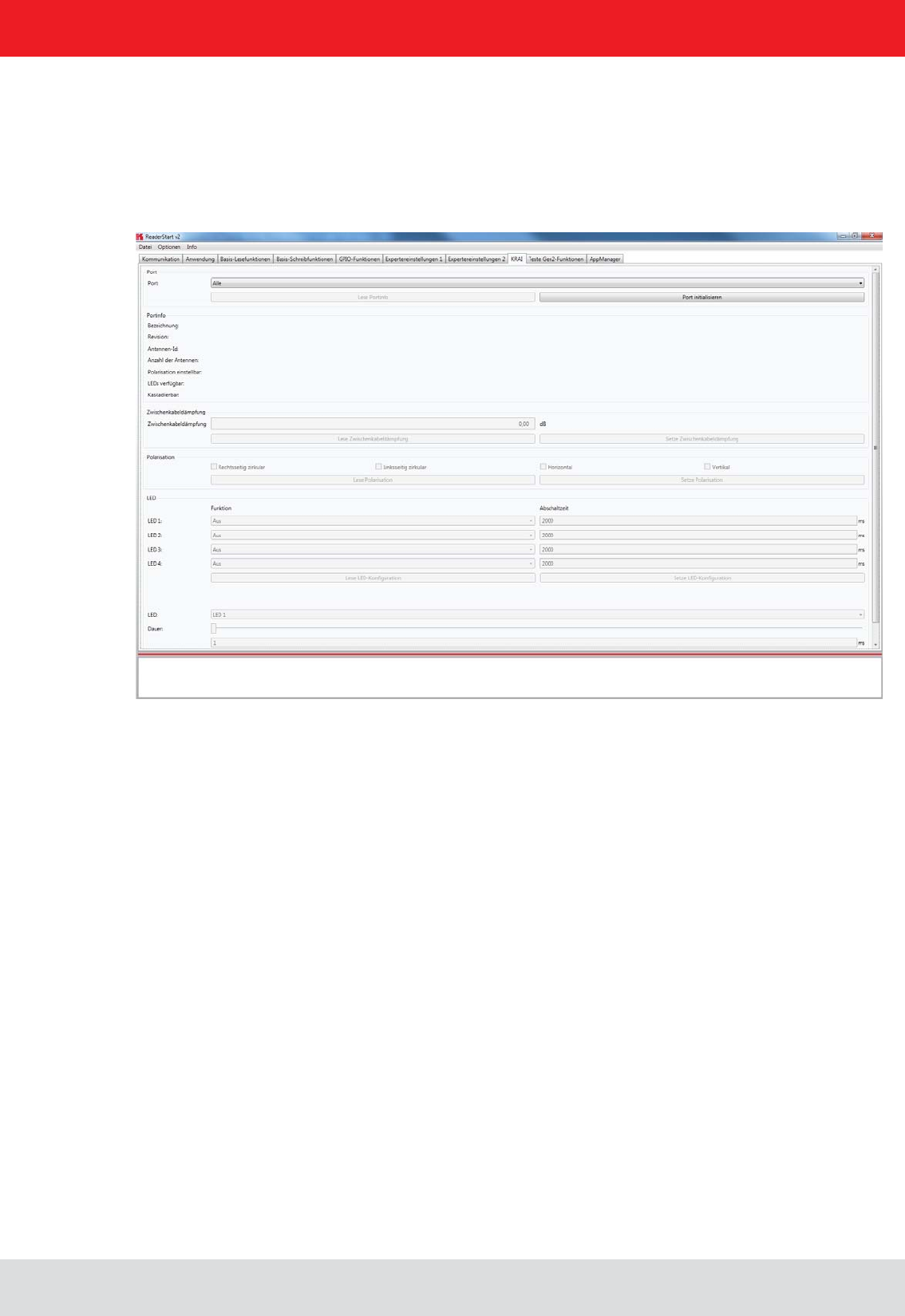
Installation manual Reader 71
English
6. Operating the reader
6.8. © KRAI-Settings
The basic settings of the reader parameters appear in this Installation Manual Reader from Chapter 6 “Descriptions and
section, under the tab "KRAI".
Figure: Overview of index card KRAI
The Reader recognises the connected antennas at boot up, but this can also be done manually by selecting a single
port or through the “All” option from the dropdown menu section port. Initialize the button port then runs the query
through the antennas in this / these ports.
characteristics depending on the antenna type and features.
Port information which had been collected through initialisation can be called up by pressing the “Read port info” button.
This action list is executed automatically by default for every port initialisation and port selection in the drop down menu.
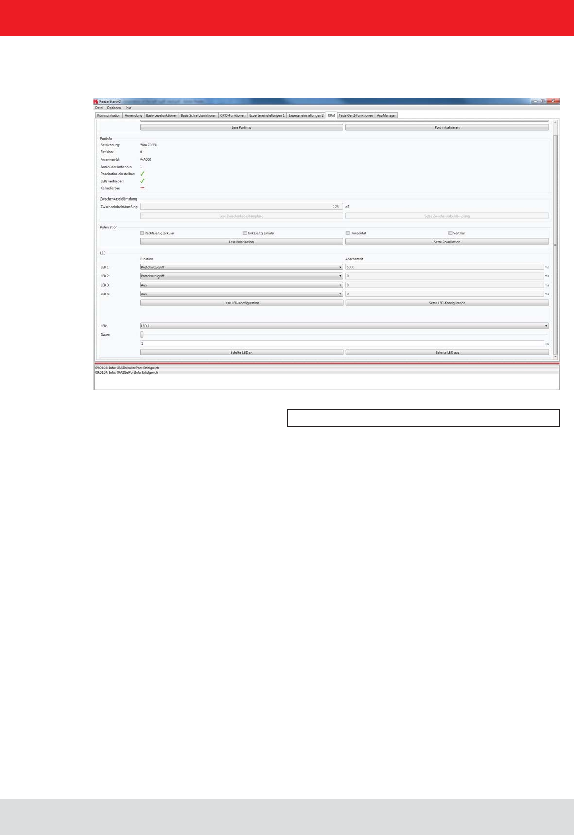
Installation manual Reader 72
English
6. Operating the reader
polarisation is for
antennas with polarisation switching, and the cable attenuation category is available for use by SmartShelf antennas.
LED.
Figure: Example WIRA with KRAI function and LEDs
In the polarisation section, the polarisation modes RHCP, LHCP, and theof the panels
can be set. If there are several types of polarisation selected at the same time in the check boxes, then the antenna
Using the button the stored information from the Reader can be called up and using the -
risation”
tab The features are as follows:
1 - Off - the selected LED is off
2 - On - the selected LED is always on
3 - RF on - the LED is active when the high frequency is fed to First to the Last antenna.
and Last antenna
6 - Operation successful tag - the output is active for milliseconds at switch off time as soon as an operation on the tag
was successful on the First to the Last antenna.
7 - Protocol - the LED can be directly switched on and off via the protocol.
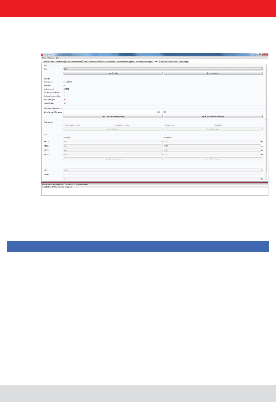
Installation manual Reader 73
English
6. Operating the reader
and
change is done immediately.
set. With buttons the LED is switched on for ms duration. The button switches off the chosen LED.
Figure: Example SmartShelf antenna with KRAI function without
LEDs
For cascadable SmartShelf antennas an absolute attenuation value is to be entered under the heading “interim cable
loss” (in 0.25 dB steps) for the lines between the antennas. The given value is set with “interim cable loss” to the reader.
Conversely, this can be called up from the reader using the button “Read interim cable loss”.
For cascading smart shelf antennas, it is necessary to use cables with the same attenuation (cable length). Otherwise
the TX-power of the antennas that is derived from the intermediate cable attenuation is not calculated correctly.
Furthermore, the value of the intermediate cable loss should be correct, so that the output power can be correctly cal-
culated and fed accordingly.
on the use of library functions. This examples are console applications. They show how to establish an connection to
how action lists are constructed.
Note

Installation manual Reader 74
English
6.9. App Manager
The AppManager manages Linux application on the Linux part of the ELC and ETL Reader. To make this possible,
each application must have the following structure:
To transfer the application data to the reader, an FTP server can be started. Select "Start FTP Server" - this enables
readers to start SW, in the menu "Options / Intelligence Module."
have set a different IP address on your system.
Alternatively, the app can be imported in the Linux system using the "install app" function.
For this purpose the app structure has to be packed in *.tar format.
Using the Reader Start software the applications can then be managed using the tab "AppManager"
6.10. Access Manager
Kathrein RFID solutions are characterised by ease of use and intuitive operation. They have extensive capabilities for
fast and secure ID applications of all kinds.
The devices of the ARU4 and RRU4 series have an optional integrated industrial PC platform based on Linux OS on
which the complete application control can be run directly on the device. A permanent data connection is not necessary!
to be collected. Programming skills are not required! Digital inputs are thereby connected/linked to digital outputs and
that can be used to control features. This allows starting points of the application to be set, in which a photoelectric or
inductive ground loop is requested to enable the reading process. When registered in the system transponder these
-
risations. Depending on these decisions up to 4 digital outputs can be connected, e.g. to allow access by opening a
barrier or a gate.
As an example, on the Kathrein RFID homepage a demo version of ACCESS Manager can be downloaded. This demo
version is limited to 5 TAGs, and can be enabled if required for up to 500 transponders.
6. Operating the reader
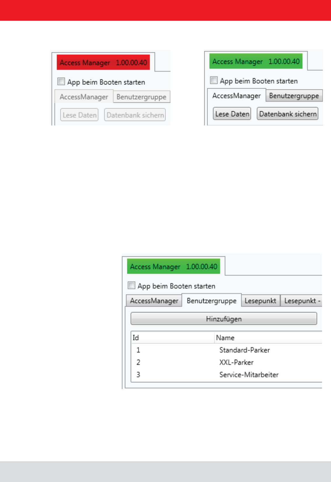
Installation manual Reader 75
English
The ACCESS Manager is activated using the button "Start app". The signal bar in the indicator changes from red to
green.
A tick in the "start app at boot" target application box will resume the app set after a power failure.
The example was set up based on the following scenario:
Vehicle detection for entry and exit in a parking garage
6.10.1. User Groups
Using "User Group / Add", the respective roles can be created and managed via delete / edit.
6. Operating the reader
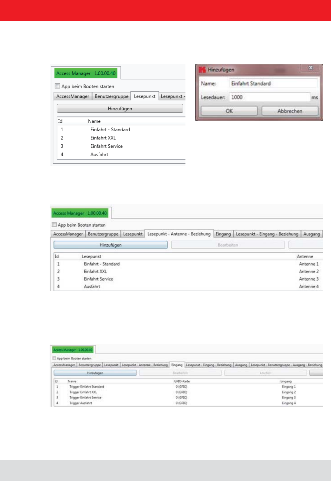
Installation manual Reader 76
English
6.10.2. Reading point
in msec.
6.10.3. Reading point - Antenna relationship
The corresponding reading points are linked to the physical antennas with the "read point antenna" relationship.
6.10.4. Entrance
loop, the impetus for RFID reading is carried out via the associated digital input.
6. Operating the reader
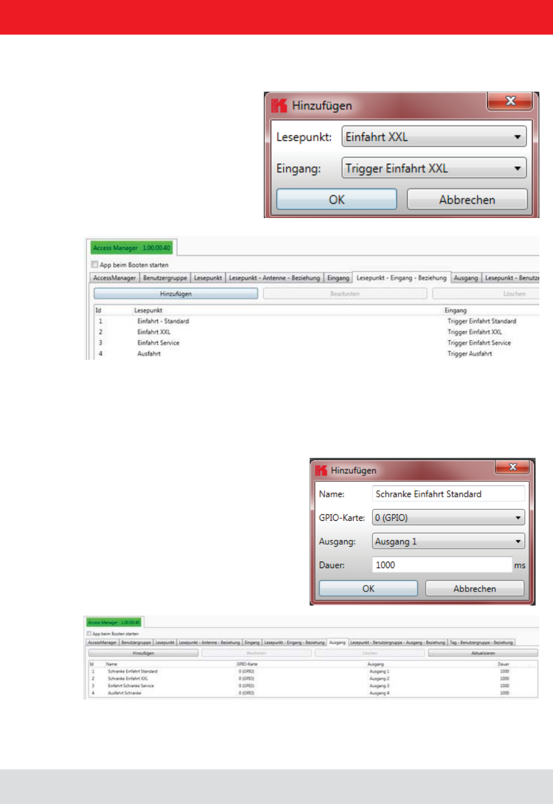
Installation manual Reader 77
English
6.10.5. Reading point – entrance relationship
With the "read point – entrance relationship" the trigger is linked to the read point.
6.10.6. Output
Then, the digital outputs are allocated. This will then set which action should take place (here enable barrier = entrance
open), and also which digital output is activated (output 1) and how long the switching pulse will be.
6. Operating the reader
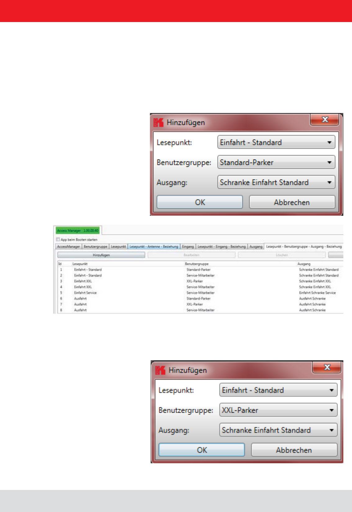
Installation manual Reader 78
English
6. Operating the reader
6.10.7. User Groups
The permissions are distributed through the relationship between reading points, user groups and the outputs. Here, of
course, a user group (in this case service employees) can have access to multiple reading points.
6.10.8. Read point - User Group - Output - relationship
The next tab shows the allocation of read points, user groups and outputs.
Please note that all authorised users groups are also listed for each read point. Thus, in the example at the "entrance
- standard" only "standard - Parker" can drive in "service employees". Should "XXL Parker" also be issued an access
permit to this area of the car park, it must also be linked in.
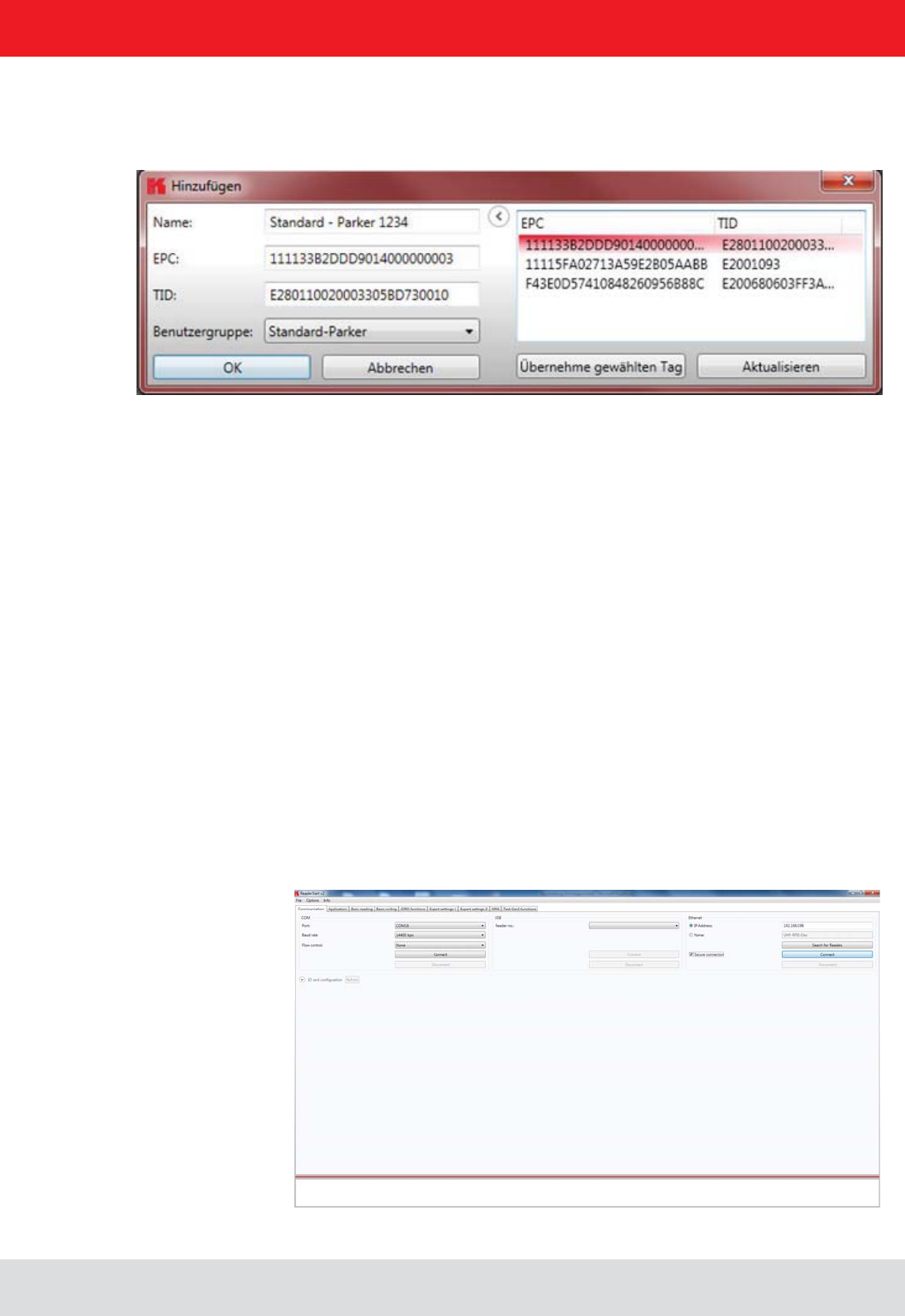
Installation manual Reader 79
English
6. Operating the reader
6.10.9. Tag – User Group relationship
Finally, the unique transponders are assigned to the respective representatives of the user group, so as to achieve an
This can be either a “Name”, “Username” or “ID”.
via the menu item “Update”.
With “Accept the selected tag” the EPC and TID of the selected transponder is transferred to the mask.
At the end the tab “Tag-user Group relationship” is used to assign the user to his user group.
Since the processing of the Access Manager runs immediately into a SQL database on the Linux part of the reader,
the transponder is also connected immediately. It is recorded in the corresponding driveways, after the triggering of the
trigger and depending on its corresponding privileges, the barrier is opened or access is denied. Upon completion of
processing, the Ethernet cable can be removed. The application runs autonomously on the Linux part of the Kathrein
UHF RFID ETL / ELC Reader
6.11. Ethernet password
Secure Shell (SSH):
has to be selected.
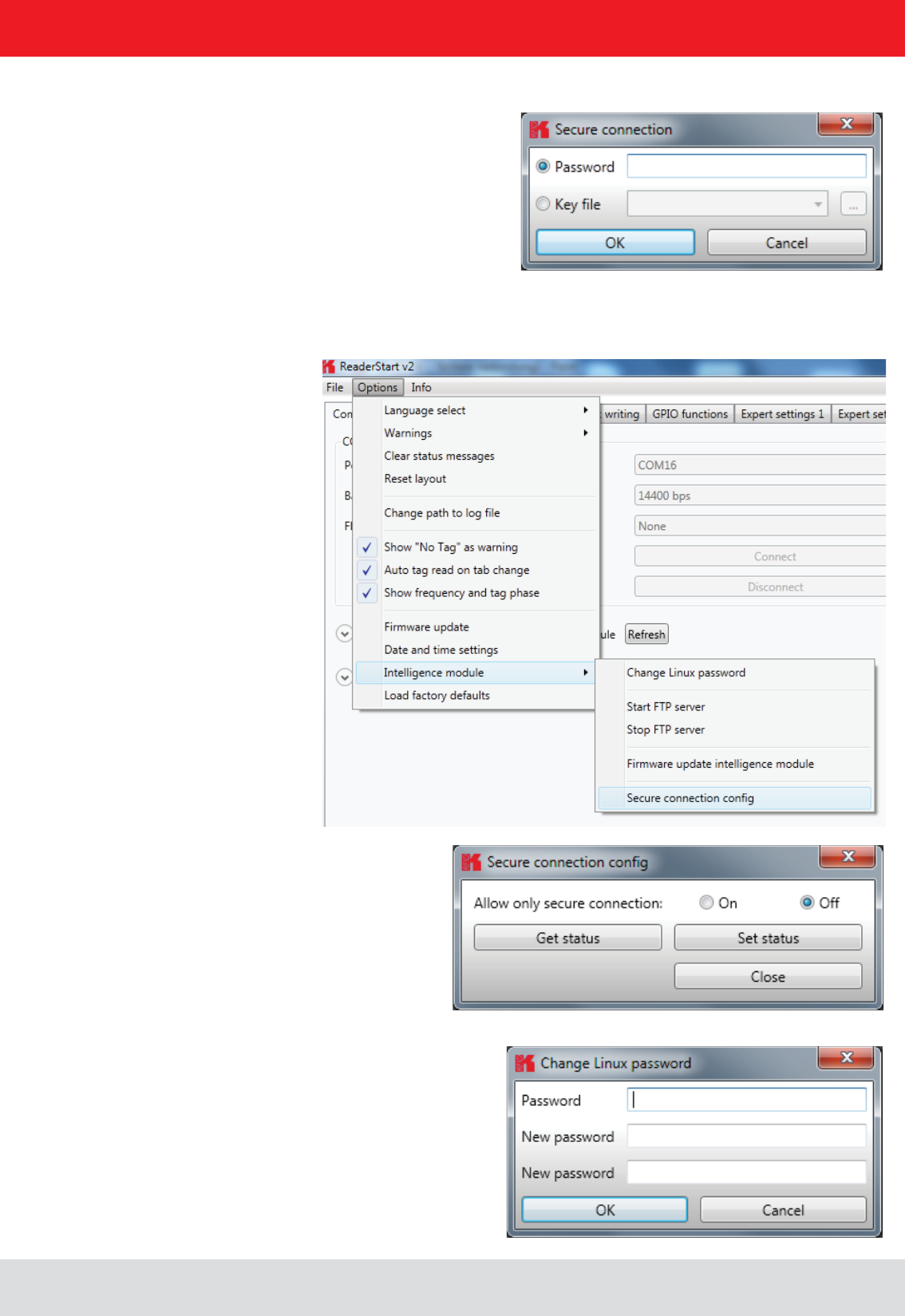
Installation manual Reader 80
English
6. Operating the reader
The password can be changed with “Change Linux password”
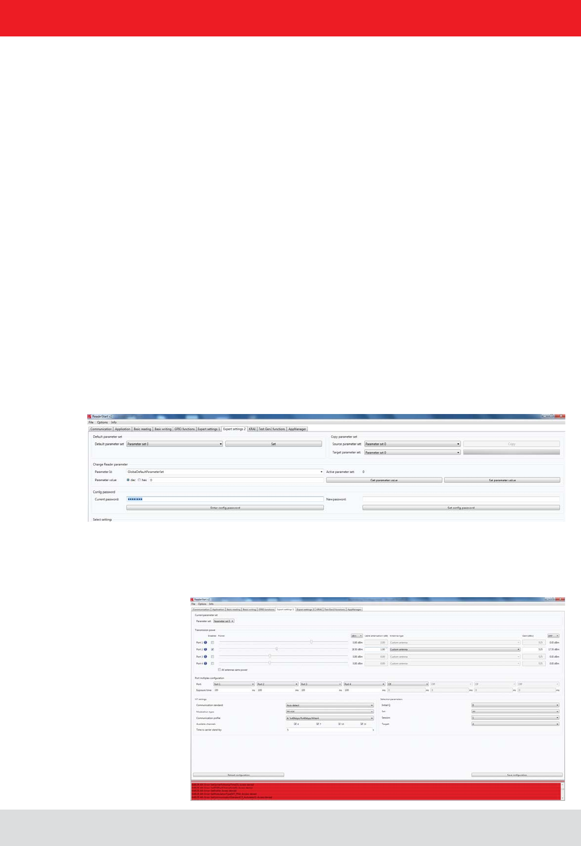
Installation manual Reader 81
English
6. Operating the reader
* SetCommunicationStandard
* SetPortPower
* SetCarrierFollowUpTime
* SetPortMultiplexSequenceAndExposureTime
* SetCableLossAndAntennaGain
* SetETSIPortChannelList
* SetETSIPortChannelSwitchingMode
* SetModulationType
* SetExtendedResultFlag
* SetDefaultParameterSet
* SetActiveParameterSet
* SetTime
* SetAntennaMapping
* LoadFactoryDefaults
* FirmwareUpdatePrepare
* SetSelSessionAndTarget
* SetInitialQ
* SetMaxAirCommErrors
* SetASyncObservedListParameters
After entering the password you have 30 seconds to perform changes. Each time you save the changes, the expire
time is extended by another 30 seconds. If you want to save changes after the 30 seconds, you get the system mes-

Installation manual Reader 82
English
7. Programming the Reader
7.1. Preparation
For the integration of the reader into an existing application on Windows, Linux for operation as a standalone device
The user has the choice to use the appropriate target system library for Windows or Linux, or to implement KBRP
programming in C #, C + + and VB.Net. These examples are based on the use of the library functions. This is a console
application that shows how the connection is established to the reader and how tags are read, GPIOs used and action
lists are built.
The examples have been tested on Windows 7 and Debian 6.0. Before the programs are compiled, the environment
must be adapted. Copy the folder / AP and / RFIDDemoApp in your user directory. For the preparation of programs for
an Embedded Linux, an Embedded Linux Development Kit must be installed. For more information on the installation,
please see Chapter 7.6.
Note
to be adapted to your building in the reader and in the source code of the program.
The necessary libraries for the programs can either be stored in the respective program folder or the default library
folder of the operating system.
Now, the programs can be created using the following procedure.
The same source code can be used in Linux. A distinction is made as follows:
the program Console Linux demo is created in the same folder.
can be copied to the / urs / lib (libReaderLib.so cp / usr / lib ) or will be stored in the folder with the source code. Then
the program with. / Console Linux demo can be started.
7.5. Using on an embedded system
If the example is to be complied for the embedded system of an ETL or ELC reader, the ELDK must be installed for the
corresponding target System on Linux. The process for this is described in Chapter 7.7. The cross compiler creates the
program for the target system.
Note
The program created will only run on the target system.

Installation manual Reader 83
English
7. Programming the Reader
Note
One way to transfer the data is described in Section 7.7.
The ELDK is a development tool, which includes cross-compiler tools and furthermore useful programs, included al-
ready compiled for the target (eg libraries or user programs) provides.
creation of the CD / DVD. Newer versions can be downloaded at the following address
ftp://ftp.denx.de/pub/eldk/
(at the time of this writing, eg "version number" = 5.3). The directory structure is then given by
with mkdir / mnt / tmp)
mount -o loop /tmp/eldk-X.X.X-armvXX.iso /mnt/tmp
Next change to the mount directory
cd /mnt/tmp
and run the following command
./install.sh -s qte -r - armvXX
The ELDK is then installed by default in the / opt directory. There, the tools can be found. In the following directory
/opt/eldk-X.X.X/armvXX/sysroots/i686-eldk-linux
/opt/eldk-X.X.X/armvXX/sysroots/armvXX-vfp-neon-linux-gnueabi
compiled tools can be found within the directory.
This can be completed using the following command
umount /mnt/tmp
rm -f /tmp/eldk-X.X.X-armvXX.iso

Installation manual Reader 84
English
7. Programming the Reader
CROSS_COMPILE := arm-linux-gnueabi-
ARCHITECTURE_CFLAGS := -march=armv7-a -mthumb-interwork
TARGET_ARCHITECTURE := arm
ifndef NO_CROSS_COMPILE
endif
target (the ARM controller). Adaptations for the EDLK version (here eldk-5.1 or ARMv7A) or the directory structure may
be necessary.
Note
The created program will run only on the target system.
Note
When the build process was successful, the program can be transferred to the reader. A possible way to transmit the
data is described in ().

Installation manual Reader 85
English
7. Programming the Reader
The reader is equipped with a separate module, running a linux on it. That gives the user the opportunity to install an
do this it is necessary to copy the application and the script, which starts the application, to the target and make both
executable.
Requirements:
- RRU4-ETL-xx/ ARU-ETL-xx
- Ethernet connection to the reader
- For connecting to the Reader a client like putty ((F))
- ftp client e.g. ftp (for Windows you can use the Explorer)
- the user application
For writing and compiling an application please use the manual for the Reader.
First make a connection to the reader by opening a command shell:
where ip_address is the address of your reader. Per default this address is 192.168.0.1. The default login data is “root”
with the password “UHF-RFID-Dev”.
To copy a program to the reader ftp is used. Therefore the ftp server on the reader needs to be started. This can be
done via telnet by calling
from the command line.
Now it is possible to establish a connection to the reader via ftp. To do so, open another command-shell, go to the
directory of the application to copy and start the ftp client e.g.:
ftp ip_address
where ip_address is the address of you reader. Login name is “root”, no password is required. If there is a problem
To copy the application use
# put
the server can be stopped. The FTP service is also stopped after a reboot.
use
# chmod permission_owner permission_group permission_other application
granted otherwise it is not. At least the application should be executable. Application is the name of the application on
the target. To give the permission to read and execute to all 3 groups it should look like this:
# chmod 555 application

Installation manual Reader 86
English
So now we have an application in the non volatile memory on the target that is allowed to be executed. The next and
last step is to make it bootable by default after power up. During boot process the script inittab is called. This script
looks for a script named
startup
in the directory
The linux will execute its content on every boot. Therefore we need to add the programcall in that script. Below is an
example shown, how this can be done from the commandline on the reader:
When you need to modify the script, take use an editor that can handle Unix line breaks at the end of each line (0x0A),
the normal windows carriage return and linefeed in the script won’t work.
7. Programming the Reader

Installation manual Reader 87
English
8. List of references
((E)) EPCTM Radio-Frequency Identity Protocols Class-1 Generation-2 UHF RFID in version V1.2.0 :
www.epcglobalinc.org
((A)) for software developers
((B)) for commissioning
((C)) Setup and installation
"installation manual antenna“ ((D)) Setup and installation
((E)) for software developers
((F)) for software developers

address contact
Kathrein RFID
Kronstaudener Weg 1
D-83071 Stephanskirchen
9. contact address
Installation manual Reader 88
English