KYOCERA Document Solutions B5J0451 RFID Reader/Writer for printer User Manual 2 of 2
KYOCERA Document Solutions Inc. RFID Reader/Writer for printer 2 of 2
Contents
- 1. User Manual 1 of 2
- 2. User Manual 2 of 2
User Manual 2 of 2
Loading Paper
OPERATION GUIDE 2-19
NOTE: If the paper is considerably curled in one direction, for example, if
the paper is already printed on one side, try to roll the paper in the
opposite direction to counteract the curl. Printed sheets will then come out
flat.
6Set the MP tray paper size using KM-NET for Clients or COMMAND
CENTER. Refer to the utility manuals for further information.
Loading Thick Paper and Envelopes into the MP (Multi-Purpose) Tray
To print on thick paper and envelopes, follow the instructions below.
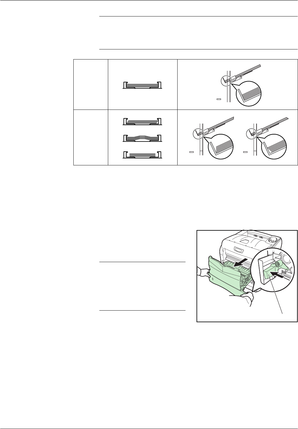
1While pulling the green release
lever, pull out the paper transfer
unit.
NOTE: When you pull out the
transfer unit together with the
paper casette, a bottom plate
of the paper casette may lift.
Push the bottom plate down
until it locks.
Correct
Incorrect
Release Lever
Loading Paper
2-20 OPERATION GUIDE
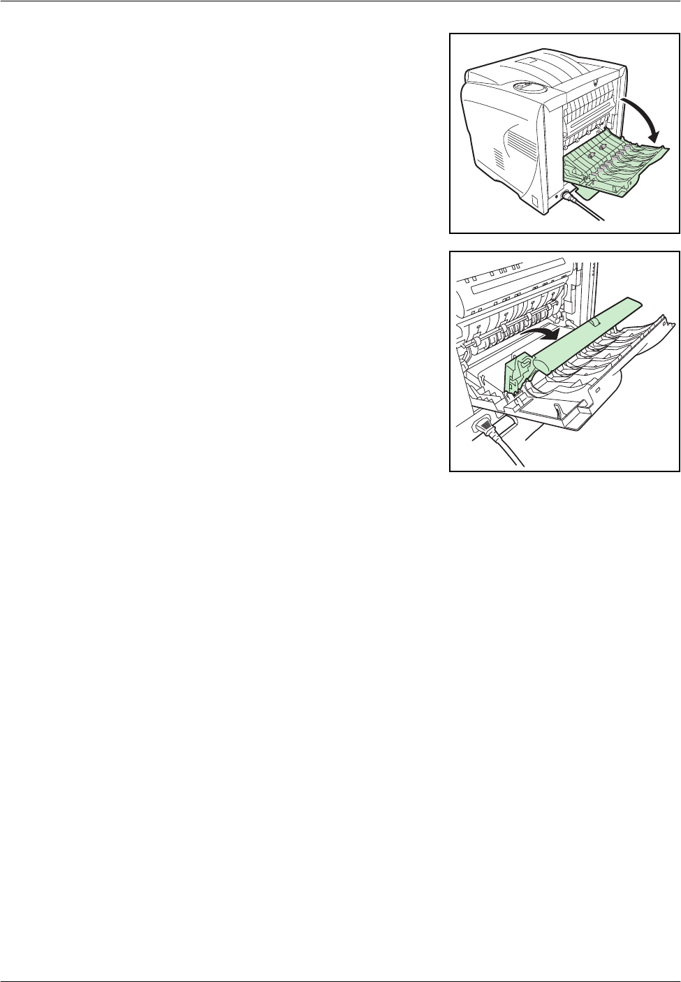
2Open the rear cover.
3Pull the rear paper path and open
it.
Loading Paper
OPERATION GUIDE 2-21
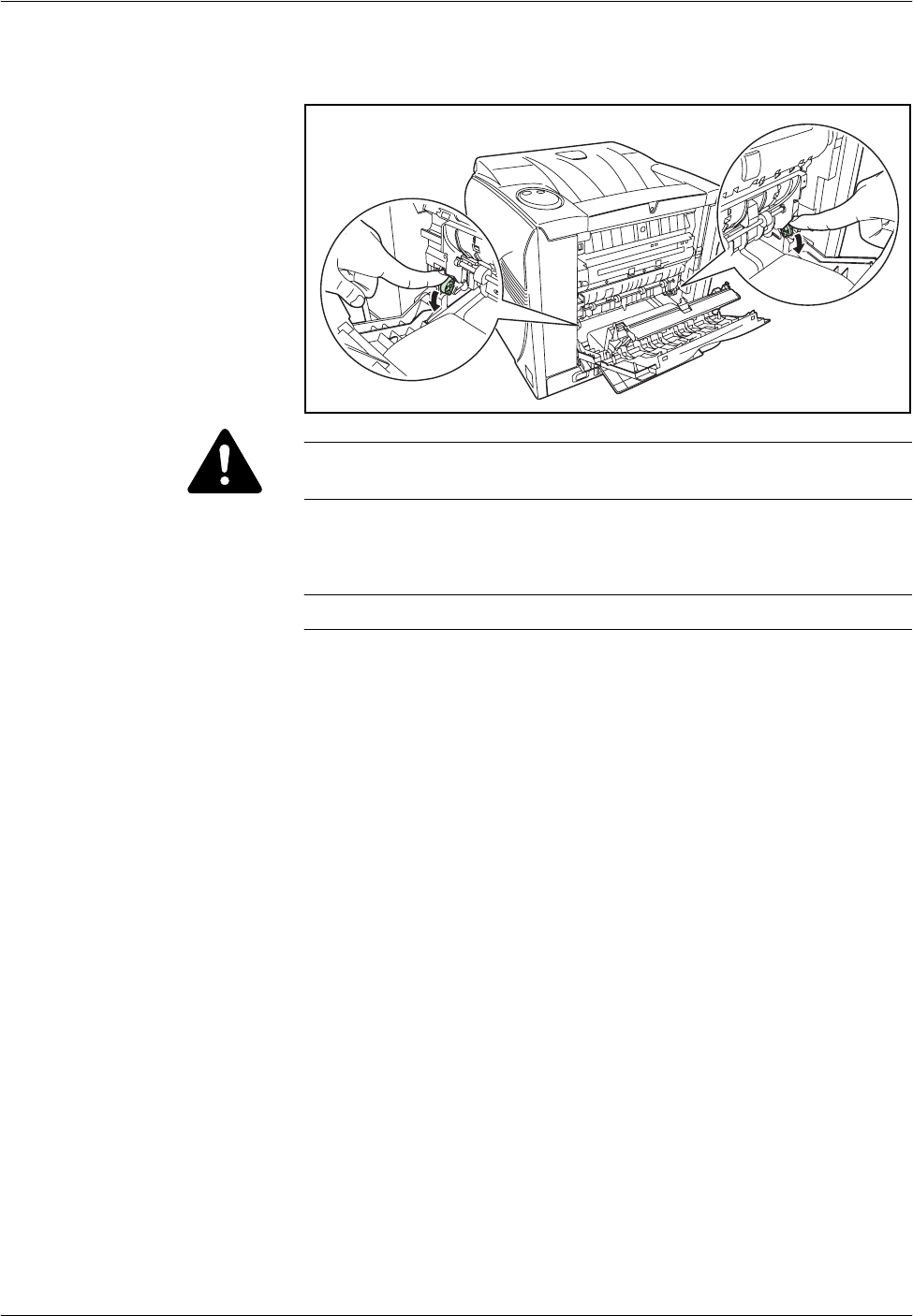
4Press the green levers to change the thickness of paper.
CAUTION: The fuser unit inside the printer is hot. Do not touch it, as it
may result in burn injury.
5Close the rear paper path and rear subcover, then push the paper transfer
unit back in completely.
NOTE: Leave the rear cover open to print on the envelope.
6Fan the media (thick paper/envelopes), then tap it on a level surface to
avoid media jams or skewed printing.
7Pull the MP tray towards you until it stops.
8Pull out the subtray.
9Adjust the position of the paper guides on the MP tray. Standard paper
sizes are marked on the MP tray. For standard paper sizes, slide the paper
guides to the corresponding mark.
10 Align the paper with the paper guides and insert as far as it will go.
11 Set the MP tray paper size using KM-NET for Clients or COMMAND
CENTER. Refer to the utility manuals for further information.

Loading Paper
2-22 OPERATION GUIDE

OPERATION GUIDE 3-1
3Printing
This chapter contains explanations on the following topics:
•Connections ................................................................. 3-2
•Resolving IP address ................................................... 3-4
•Loading Software ......................................................... 3-6
•Configuring Printer Settings ......................................... 3-7
•Printing from Application Software ............................... 3-8
Printing
3-2 OPERATION GUIDE
Connections
Connecting the USB Cable
1Connect the USB cable (not included) to the USB Interface Connector.
NOTE: Use a USB cable with a rectangular Type A plug and a square
Type B plug. The USB cable should be shielded and no longer than 5
meters (16 feet) long.
2Connect the other end of the USB cable to the computer’s USB interface
connector.
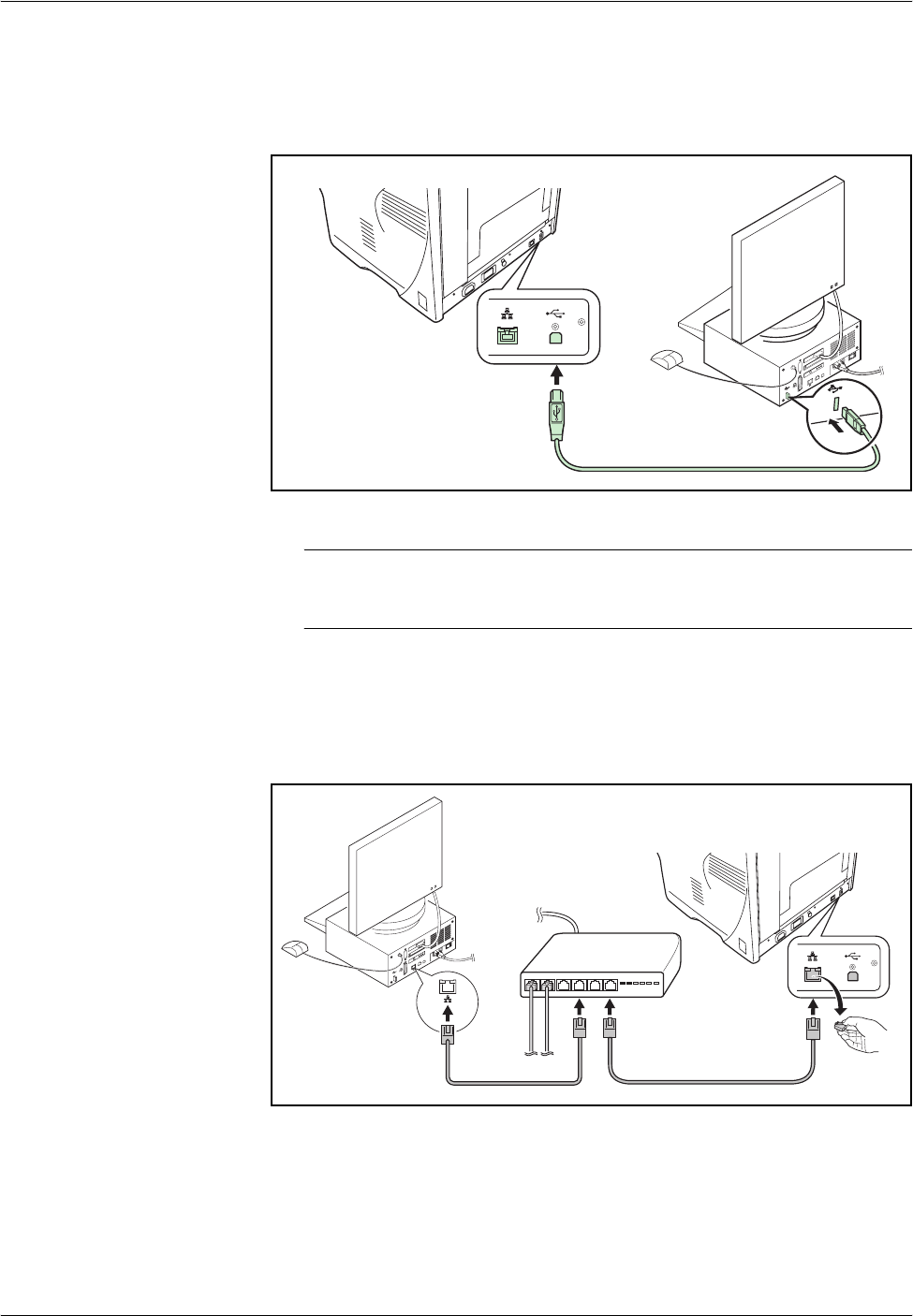
Connecting the Network Cable
1Remove the cap and connect the shielded network cable (not included) to
the computer and the hub (concentrator).
2Connect the other side of the network cable to the Network Interface
Connector at the rear of this machine and the hub.
Printing
OPERATION GUIDE 3-3
Connecting to Power
Install the printer close to an AC wall outlet. If an extension cord is used,
the total length of the power cord plus extension should be 5 meters (16
feet) or less.
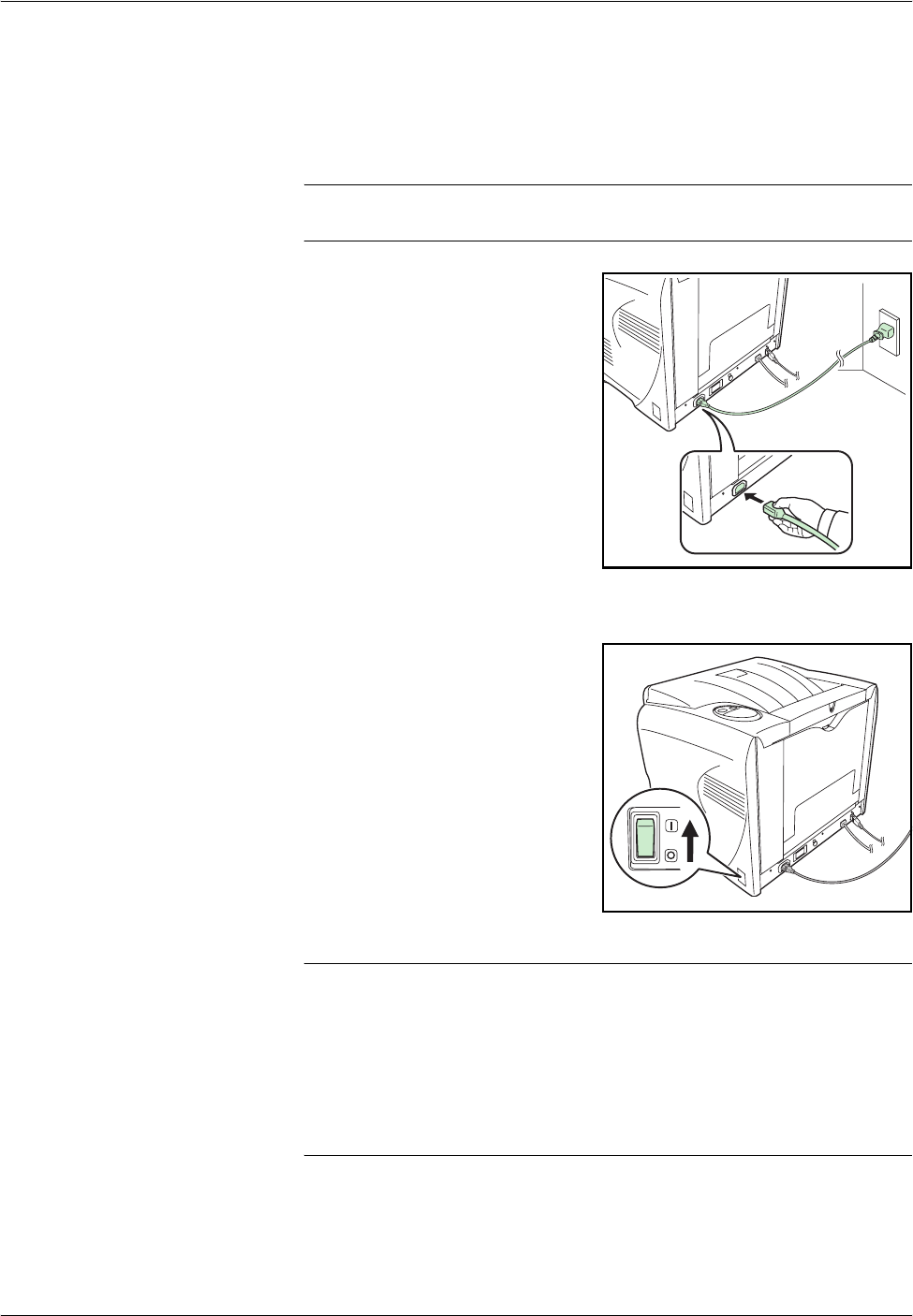
NOTE: Ensure the printer’s power switch is off. Only use the power cord
supplied with the printer.
1Connect the power cord to the
Power Cord Connector at the rear
of this printer.
2Connect the other end of the power cord to a power outlet.
3Press the Power Switch to On ( | ).
The printer will begin to warm up.
IMPORTANT: If you install the Toner Container and switch on the power,
four indicators will start rapidly flashing. When the printer is first switched
on after toner installation, there will be a delay of approximately 20 minutes
before the printer is ready to print. Once the Ready indicator lights up,
printer installation is complete.
If you turn the power off, you have to wait for an interval of five or more
seconds before turning it back on.
Printing
3-4 OPERATION GUIDE
Resolving IP address
After you connected the machine with a network cable, you can change or
verify the network settings such as IP address and default gateway using
KYOCERA COMMAND CENTER (hereinafter referred to as COMMAND
CENTER). COMMAND CENTER refers to the home page embedded in
this printer.
Requirements
If the printer is used on a TCP/IP network and has a valid IP address, it may
be managed from any web browser. The web browser allows full
configuration of all printer settings.
When accessing COMMAND CENTER, make sure that:
• The TCP/IP protocol is installed on the PC to access COMMAND
CENTER.
• DHCP server is configured to assign the IP address.
• The IP address is configured for the printer.
Required operating systems (OS) for using COMMAND CENTER:
• Microsoft Windows 98SE/Me/2000/XP, Microsoft Windows NT 4.0
• Apple Macintosh OS X 10.x
COMMAND CENTER has been tested with the following web browsers.
Changing or verifying the network settings
Follow these steps to access to COMMAND CENTER with a web browser
and change or verify the network settings.
1Press [Go] for 3 to 10 seconds to print a status page. For more details,
refer to Keys on page 1-6.
2Run the web browser.
OS Web Browser
Microsoft Windows Microsoft Internet Explorer 5.5 and 6.0
Netscape 7.1 or later
Opera 7 or later
Mozilla 1.5 or later
Apple Macintosh Netscape 7.1 or later
Safari 1 (OS X 10.2 and later)
Printing
OPERATION GUIDE 3-5
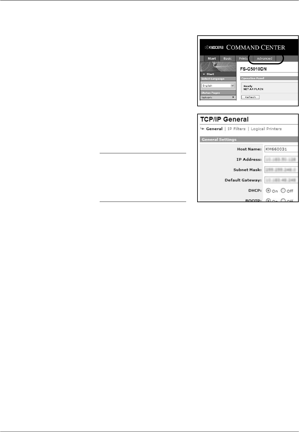
3In Address, enter the printer’s IP address printed on a status page as the
URL. The home page displays basic information about the printer.
4Click Advanced to open the
Advanced page which includes
advanced settings apply to the
printer and is comprised primarily
of advanced network settings.
5In General Settings, change the
network settings such as IP
Address, Subnet Mask, and
Default Gateway if necessary.
NOTE: You can also change
the other settings using
COMMAND CENTER. For
details, refer to KYOCERA
COMMAND CENTER
Operation Guide.

Printing
3-6 OPERATION GUIDE
Loading Software
Ensure the printer is plugged in and connected to the PC before installing
the printer driver and the other utilities from the CD-ROM.
1Switch on the PC and start Windows.
NOTE: When the printer is conncted to the PC with a USB cable, if the
Welcome to the Found New Hardware Wizard dialog box displays,
select Cancel.
2Insert the CD-ROM supplied with the printer into the optical drive of the
computer.
3The installation program starts.
NOTE: If the installation program fails to start, use Windows Explorer to
access the CD-ROM and double-click Setup.exe.
4Perform the procedures displayed on the installation program to install the
KX Driver and the other utilities.
Printing
OPERATION GUIDE 3-7
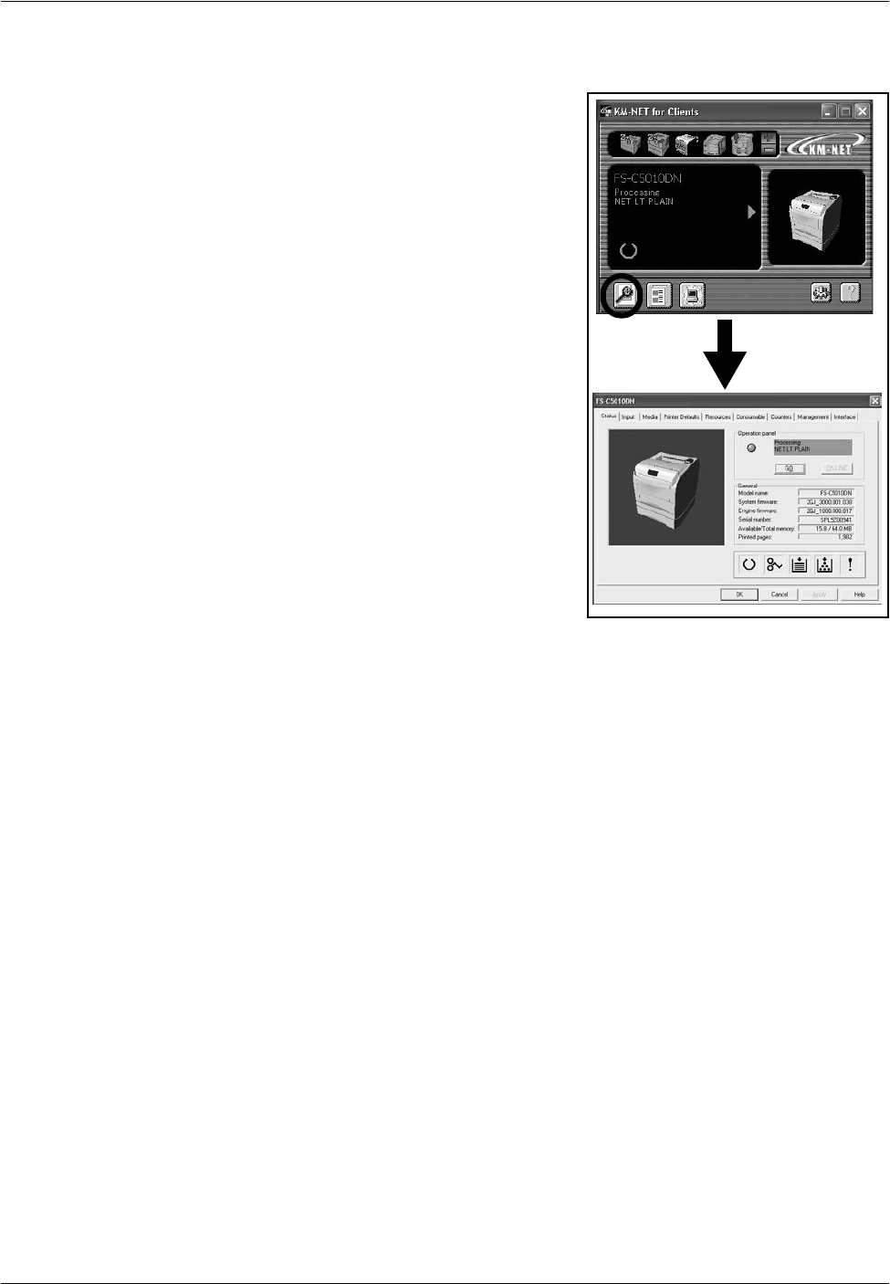
Configuring Printer Settings
You can also rely on other printer
utilities such as KM-NET for
Clients if you need to change
settings that are not available on
the printer driver. It will allow
remote access to printer settings.
Printer utilities are supplied in the
CD-ROM supplied with the printer.
Printing
3-8 OPERATION GUIDE
Printing from Application Software
The steps required to print a document created with an application are
explained below. You can select the printing paper size.
NOTE: You can also select the various settings by clicking Properties to
open the Properties dialog box.
1Load the paper required into the paper cassette.
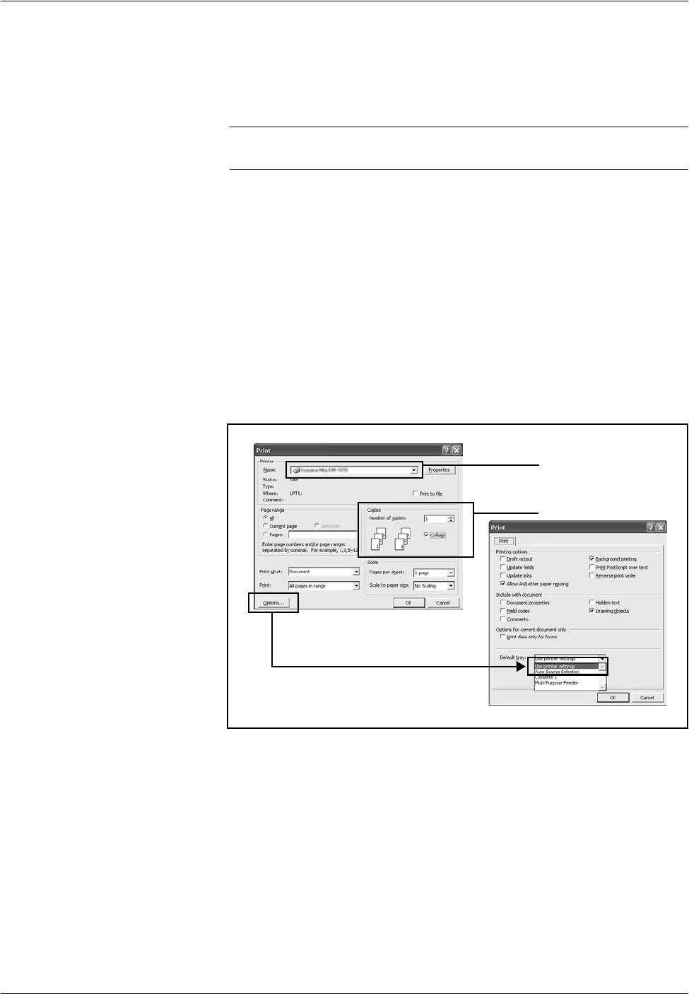
2From the application’s File menu, select Print. The Print dialog box
appears.
3Click the drop-down list of printer names. All the installed printers are
listed. Click the name of the printer.
4Use Number of copies to enter the number of copies required. Up to 999
copies can be printed.
For Microsoft Word, we recommend that you click Options and specify
Use printer settings for the Default tray.
5To start printing, click OK.
3
4

OPERATION GUIDE 4-1
4 Maintenance
This chapter contains explanations on the following topics:
•General Information...................................................... 4-2
•Toner Container Replacement...................................... 4-3
•Cleaning the Neighboring Part of the Toner Container.4-9
•Cleaning the Paper Transfer Unit............................... 4-10
•Prolonged Non-Use and Moving the Printer............... 4-12

Maintenance
4-2 OPERATION GUIDE
General Information
This chapter describes basic maintenance tasks you can perform for the
printer. You can replace the following components according to the
printer’s status:
• Toner Containers
• Waste Toner Box
Also, the internal parts need periodic cleaning.
NOTE: Information Collection on Memory Chips — The memory chip
attached to the toner container is designed to improve convenience for
the end user; to support the recycling operation of empty toner containers;
and to gather information to support new product planning and
development. The information gathered is anonymous — it cannot be
associated to any specific individual and the data is intended to be used
anonymously.

Maintenance
OPERATION GUIDE 4-3
Toner Container Replacement
Frequency of toner container replacement
The life of the toner containers depends on the amount of toner required to
accomplish your printing jobs. When 5% coverage (a typical business
document) of individual toner colors is assumed for A4 or letter size paper:
• Black toner containers last an average of 5,000 monochrome pages.
• The cyan, magenta, and yellow toner containers last an average of
4,000 or 2,000 color images.
You can print a status page to check how much toner remains in the toner
container. The Toner Gauge in the consumables status section on the
status page shows a progress bar, which roughly represents how much
toner is left in the toner container.
Starter Toner Container
The toner containers packed with new printer are starter toner containers.
The black starter toner container lasts an average of 2,000 monochrome
pages. The cyan, magenta, and yellow starter toner containers last an
average of 2,000 color images for each.
Toner Kits
It is strongly recommended that you use the new toner kit supplied from the
manufacturer to prevent printer problems and ensure a long printer life.
The toner kits are supplied in 4 different colors: cyan, magenta, yellow and
black.
A new toner kit contains the following items:
• Toner Container
• Cleaning cloth
• Three plastic waste bags for old toner container and old waste toner
box
• Waste toner box
• Installation Guide
NOTE: Do not remove the toner container from the carton until you are
ready to install it in the printer.
Understanding Indicators Requesting Toner Container Replacement
The toner indicator identifies the toner status at two stages of toner usage.
• When the printer becomes low on toner, the toner indicator flashes.
Note the replacement is not always necessary at this stage.
Maintenance
4-4 OPERATION GUIDE
• If you ignore the above status and continue printing, the indicator lights
up — just before the toner is used up. The toner container must then
be replaced immediately.
In either case, replace the toner container, refer to Toner Container
Replacement on page 4-3.
Replacing the Toner Container
NOTE: During toner container replacement, temporarily move storage
media and computer supplies (such as floppy disks) away from the toner
container. This is to avoid damaging media by the magnetism of toner.
This section explains how to replace the toner container. When replacing
the toner container, always replace the waste toner box at the same time.
If this box is full, the printer may be damaged or contaminated by the waste
toner that may spill out of the box.
NOTE: You do not have to turn printer power off before starting the
replacement. Any data that may be processing in the printer will be
deleted if you turn printer the power off.
To replace the toner container, first verify the color of the toner container
requiring replacement. The following example is for replacing a black toner
container.
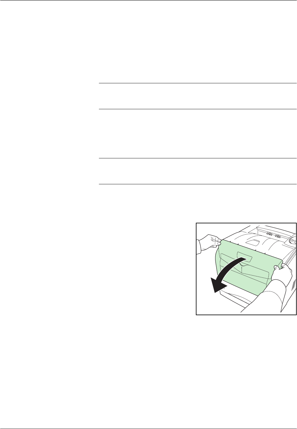
1Open the front cover.
Maintenance
OPERATION GUIDE 4-5
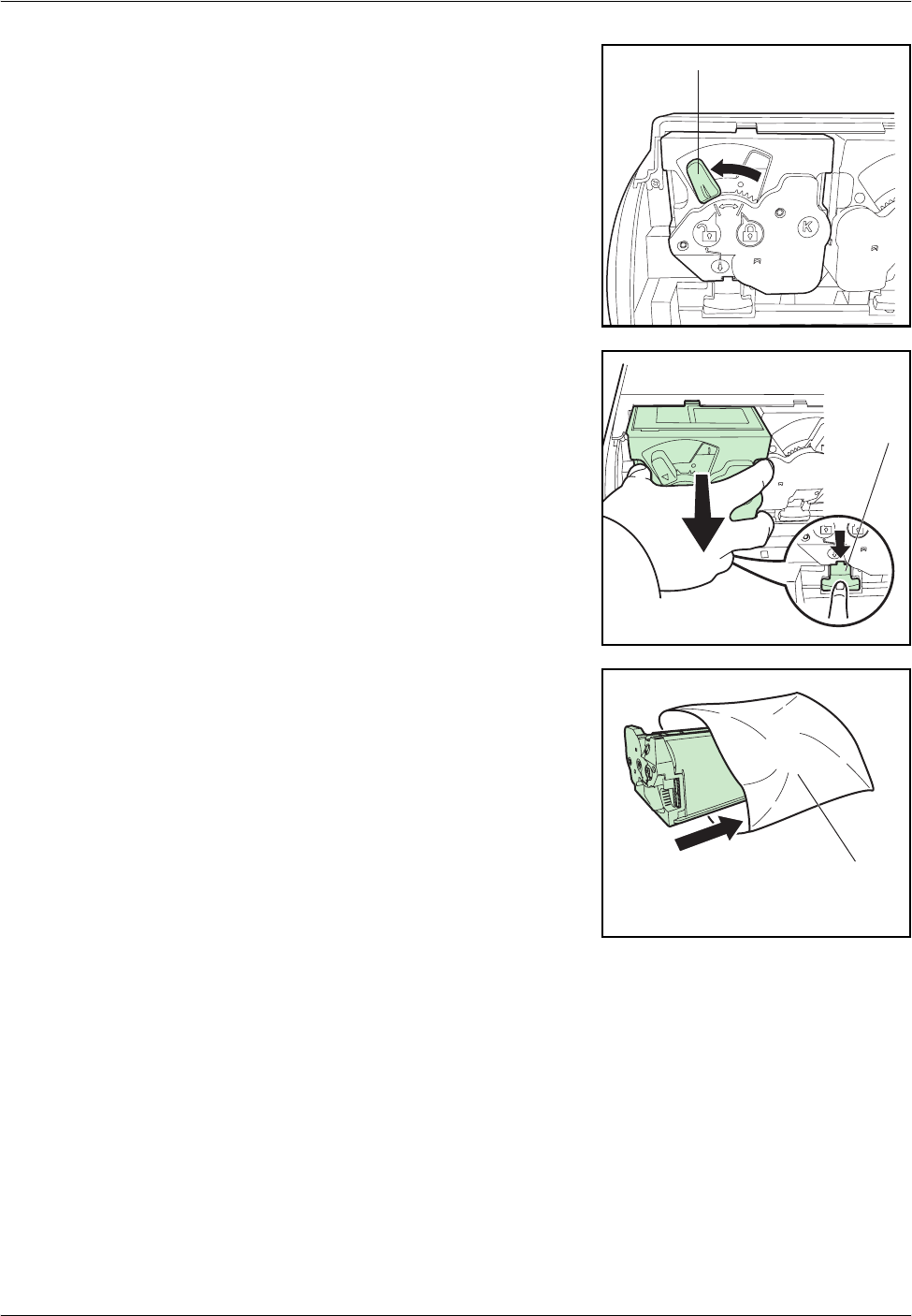
2Turn the blue lock lever on the
toner container towards the
unlocked symbol.
3Push the release lever and pull out
the toner container.
4Put the old toner container in the
plastic bag (supplied with the new
toner kit) and discard it later
according to the local code or
regulations for waste disposal.
5Take the new toner container out of the toner kit.
Lock Lever
Release
lever
Plastic Bag
Maintenance
4-6 OPERATION GUIDE
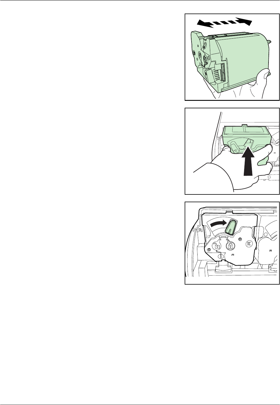
6Shake the new toner container at
least 10 times as shown in the
figure in order to distribute the
toner evenly inside the container.
7Insert the new toner container into
the printer. You will hear the
container lock into place with a
click when it is seated properly.
8Turn the blue lock lever on the
toner container towards the locked
symbol.
9Close the front cover.
Proceed to the next section.
Maintenance
OPERATION GUIDE 4-7
Replacing the Waste Toner Box
When replacing the toner container, the used waste toner box in the printer
should also be replaced with the new one from the new toner kit. The two
waste toner boxes are included with the black toner kit. The printer will not
operate without replacing the waste toner box.
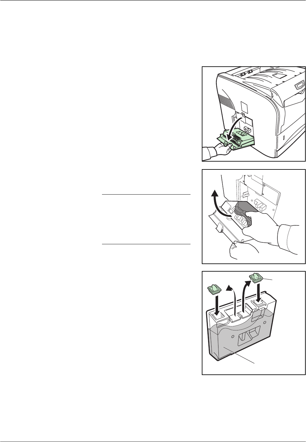
1Open the left cover.
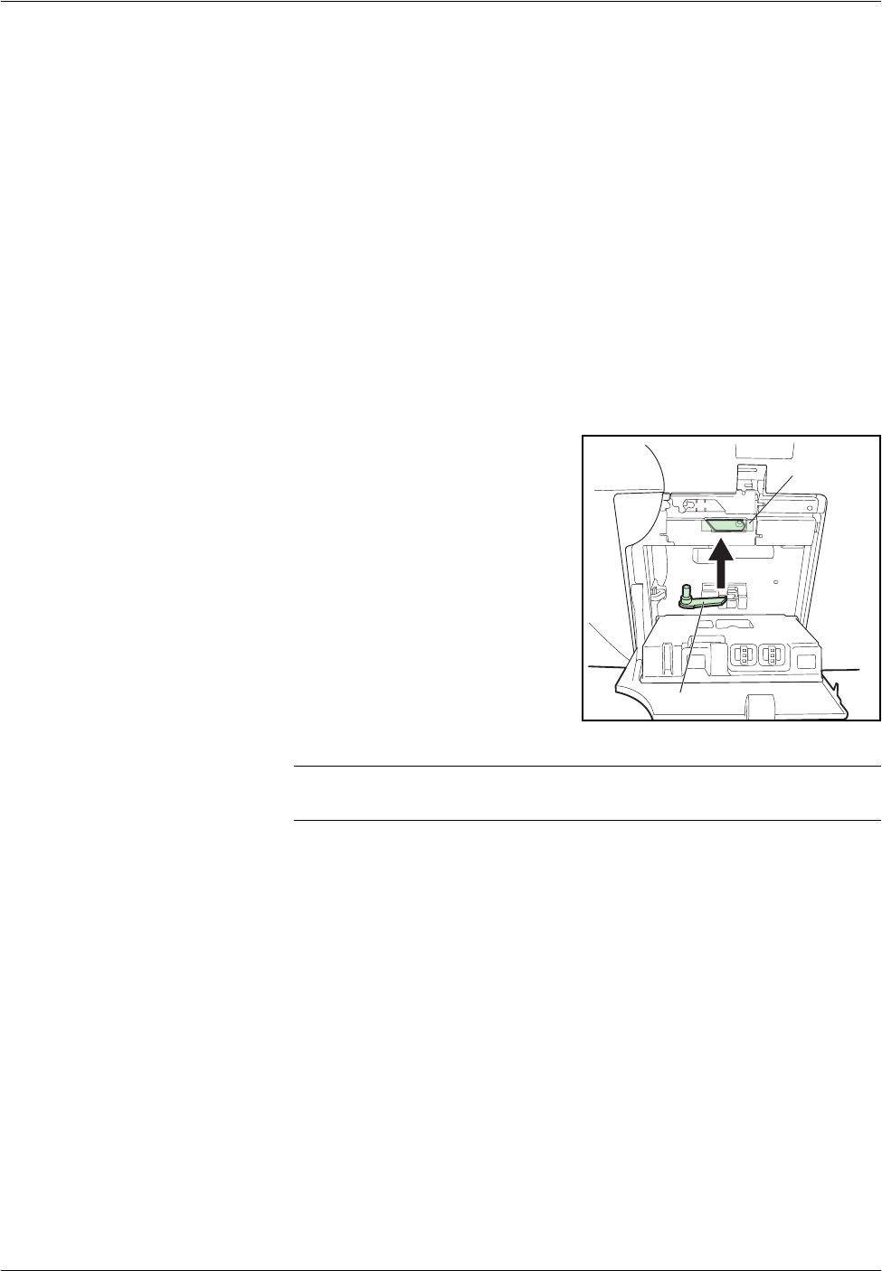
2Gently remove the waste toner
box.
NOTE: Remove the waste
toner box as gently as possible
so as not to scatter the toner
inside. Do not let the opening
of the waste toner box face
downward.
3Close the cap to the old waste
toner box after removing the box
from the printer.
Cap
Old Waste Toner Box

Maintenance
4-8 OPERATION GUIDE
4To prevent toner from spilling, put
the old waste toner box in the
plastic bag (contained in the toner
kit) and discard it later according to
the local code or regulations for
waste disposal.
5Insert the new waste toner box and close the left cover.
After replacing the toner containers and the waste toner box, clean the
internal parts. For instructions, refer to Cleaning the Neighboring Part of
the Toner Container on page 4-9 and Cleaning the Paper Transfer Unit on
page 4-10.
Plastic Bag
Maintenance
OPERATION GUIDE 4-9
Cleaning the Neighboring Part of the Toner Container
To keep the interior of the printer clean, clean the neighboring part of the
toner container.
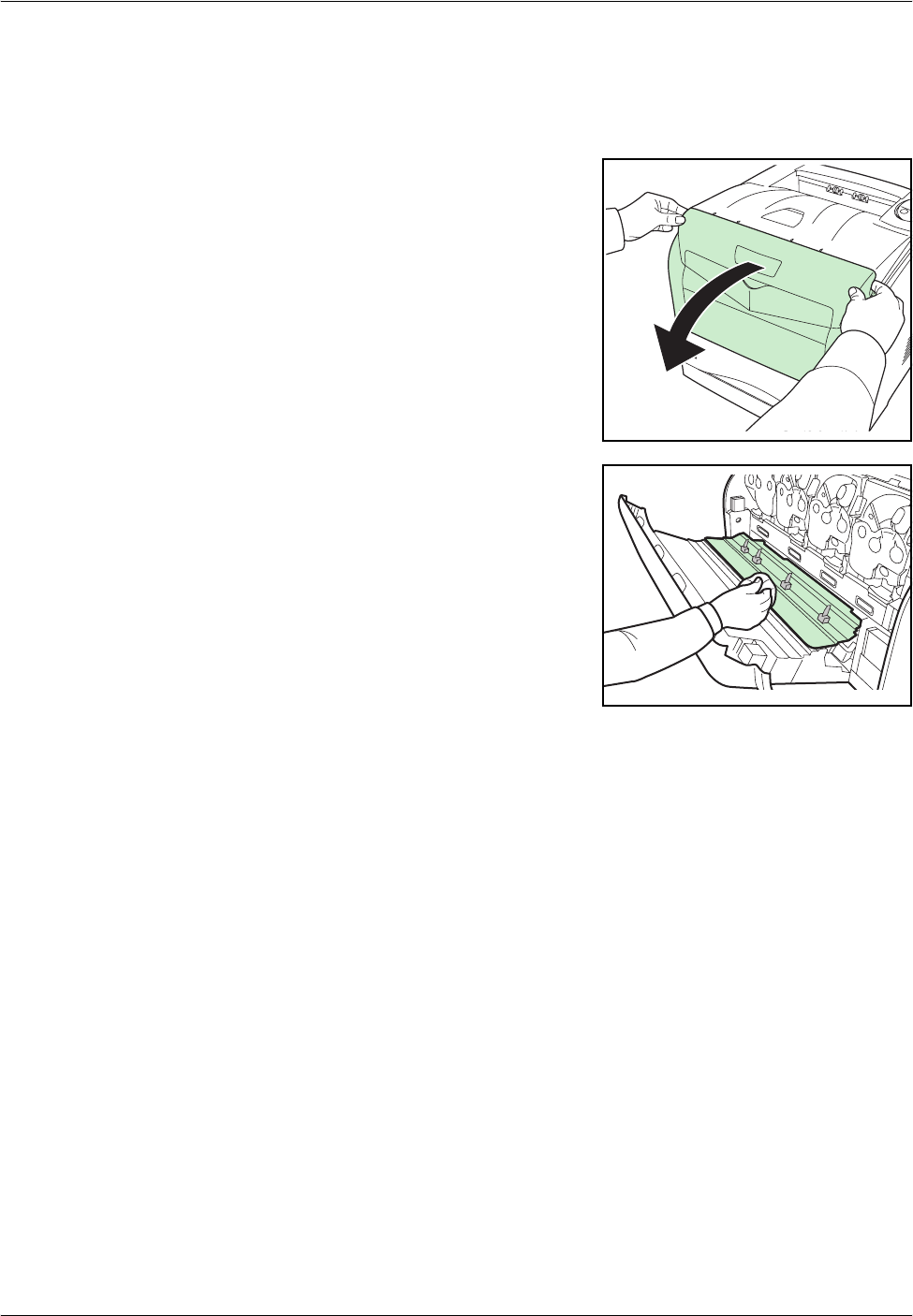
1Open the front cover.
2Use a lint free cloth to wipe away
the neighboring part of the toner
container.
3Close the front cover.
Maintenance
4-10 OPERATION GUIDE
Cleaning the Paper Transfer Unit
Print problems such as soiling of the reverse side of printed pages may
occur if the paper transfer unit becomes dirty. To clean the paper transfer
unit, you must use the cleaning cloth included in the toner kit.
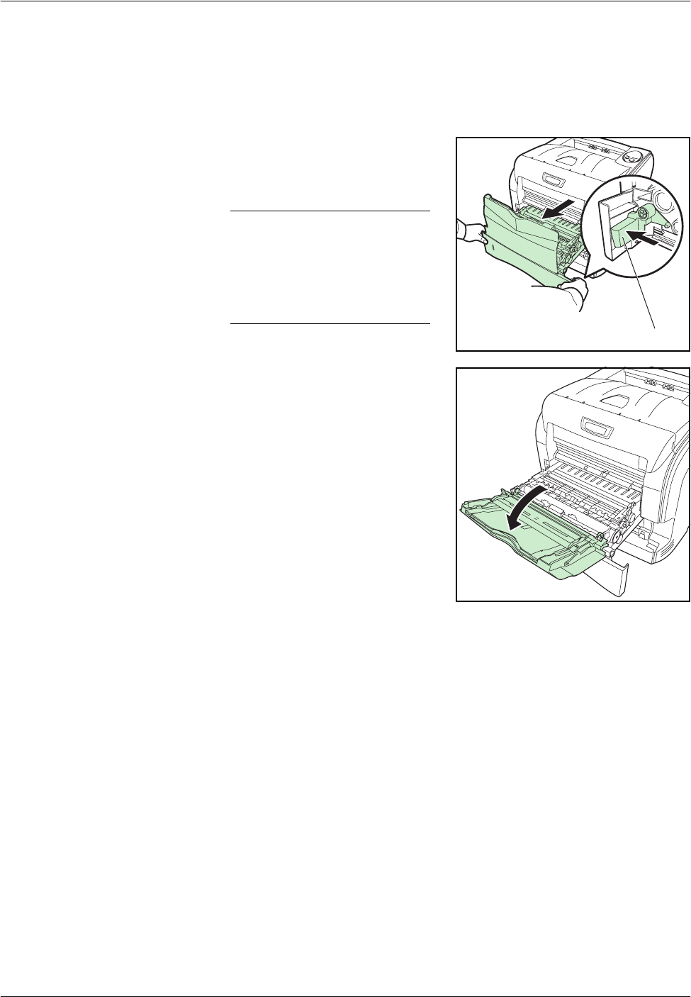
1While pulling the green release
lever, pull out the paper transfer
unit.
NOTE: When you pull out the
transfer unit altogether with the
paper casette, a bottom plate
of the paper casette may lift.
Push the bottom plate down
until it locks.
2Fold forward the cover of the
transfer unit.
Release Lever
Maintenance
OPERATION GUIDE 4-11
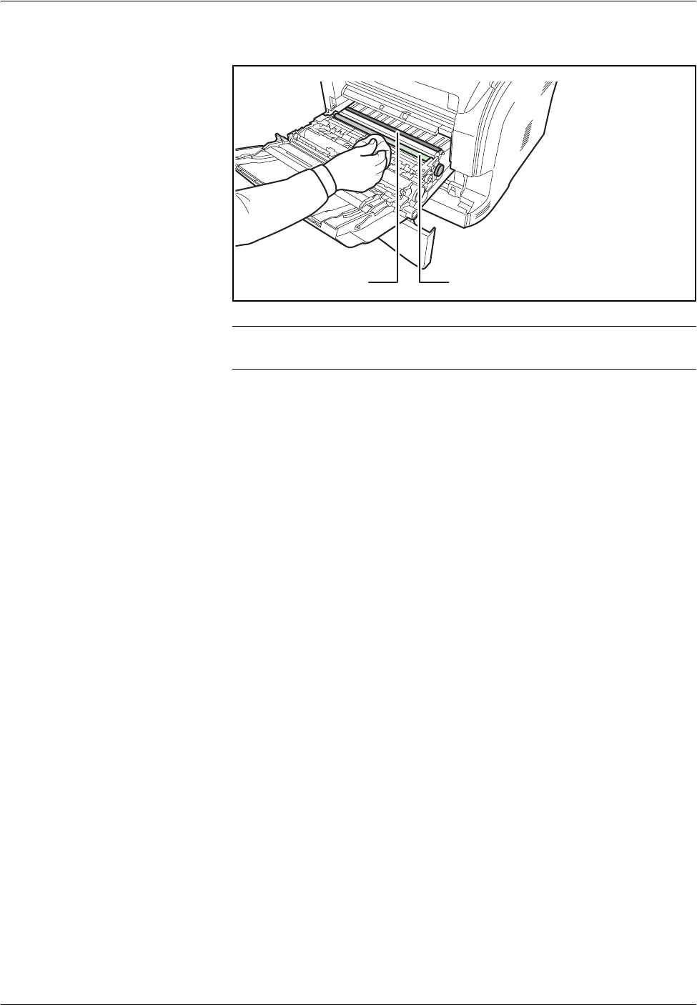
3Wipe away the paper dust on the registration roller (metal) using the lint
free cloth.
IMPORTANT: Be careful not to touch the black transfer roller as this may
adversely affect print quality.
4Push the paper transfer unit back in completely.
Black Transfer Roller Registration Roller
Maintenance
4-12 OPERATION GUIDE
Prolonged Non-Use and Moving the Printer
Prolonged Non-use
If you ever leave the printer unused for a long period of time, remove the
power cord from the wall outlet.
We recommend you consult with your dealer about the additional actions
you should take to avoid possible damage that may occur when the printer
is used next time.
Moving the Printer
When you move the printer:
• Move it gently.
• Keep it as level as possible to avoid spilling toner inside the printer.
• Attach a stopper to the left side
of the printer with fixing tape as
shown on the right. The
stopper is attached near the
waste toner box after
unpacking the printer.
IMPORTANT: Be sure to consult a service technician before attempting
long-distance transportation of the printer.
Fixing Tape
Stopper

OPERATION GUIDE 5-1
5 Troubleshooting
This chapter contains explanations on the following topics:
•General Guidelines....................................................... 5-2
•Print Quality Problems.................................................. 5-4
•Clearing Paper Jams.................................................... 5-7
If a problem cannot be corrected, contact the nearest service
technician.
Troubleshooting
5-2 OPERATION GUIDE
General Guidelines
The table below provides basic solutions for problems you may encounter
with the printer. We suggest you consult this table to troubleshoot the
problems before calling for service repairs.
Tips
Printer problems may be solved easily by following the tips below. When
you have encountered a problem that cannot be solved following the
guidelines above, try the following:
• Turn the printer power off and wait for several seconds. Then, turn on
the printer.
• Restart the computer you are using to send print jobs to the printer.
Symptom Check Items Corrective Action
The printer will not print
from the computer Check the Ready indicator. Using the information on page 1-5,
check if an error has occurred and
clear the error.
Check if a status page can be
printed. If the status page was printed
successfully, there may be a
problem with the connection to the
computer. Refer to the Installation
Guide and check the connection.
Check that the indicators
display in a recognized
combination. Refer to page 1-5
for further information.
Turn the power switch Off (O) and
then On ( | ) again. Print the job
again.
Print quality is poor Refer to page 5-4 for information.
Paper is jammed Refer to page 5-7 for information
on clearing paper jams.
The indicators are off and
the fan is not working Check the power cord. Connect both ends of the power
cord securely. Try replacing the
power cord. Refer to Installation
Guide for information.
Check the power switch is in
the On ( I ) position. Refer to the Installation Guide for
more information.
The printer prints a status
page but data from the
computer is not being
printed
Check program files and
application software. Try printing another file or using
another print command. If the
problem occurs with a specific file
or application, check the printer
settings for that application.
Check the interface cable. Connect both ends of the interface
cable securely. Try replacing the
printer cable. Refer to the
Installation Guide for more
information.

Troubleshooting
OPERATION GUIDE 5-3
• Obtain and use the latest version of the printer driver. The latest
versions of printer drivers and utilities are available at:
http://www.kyoceramita.com/download/.
• Make sure that the procedures for printing are correctly followed in the
application software. Consult the documentation supplied with the
application software.
Troubleshooting
5-4 OPERATION GUIDE
Print Quality Problems
The tables and diagrams in the following sections define print quality
problems and the corrective action you can conduct to solve the problems.
Some solutions may require cleaning or replacing parts of the printer.
If the suggested corrective action will not solve the problem, call for
service.
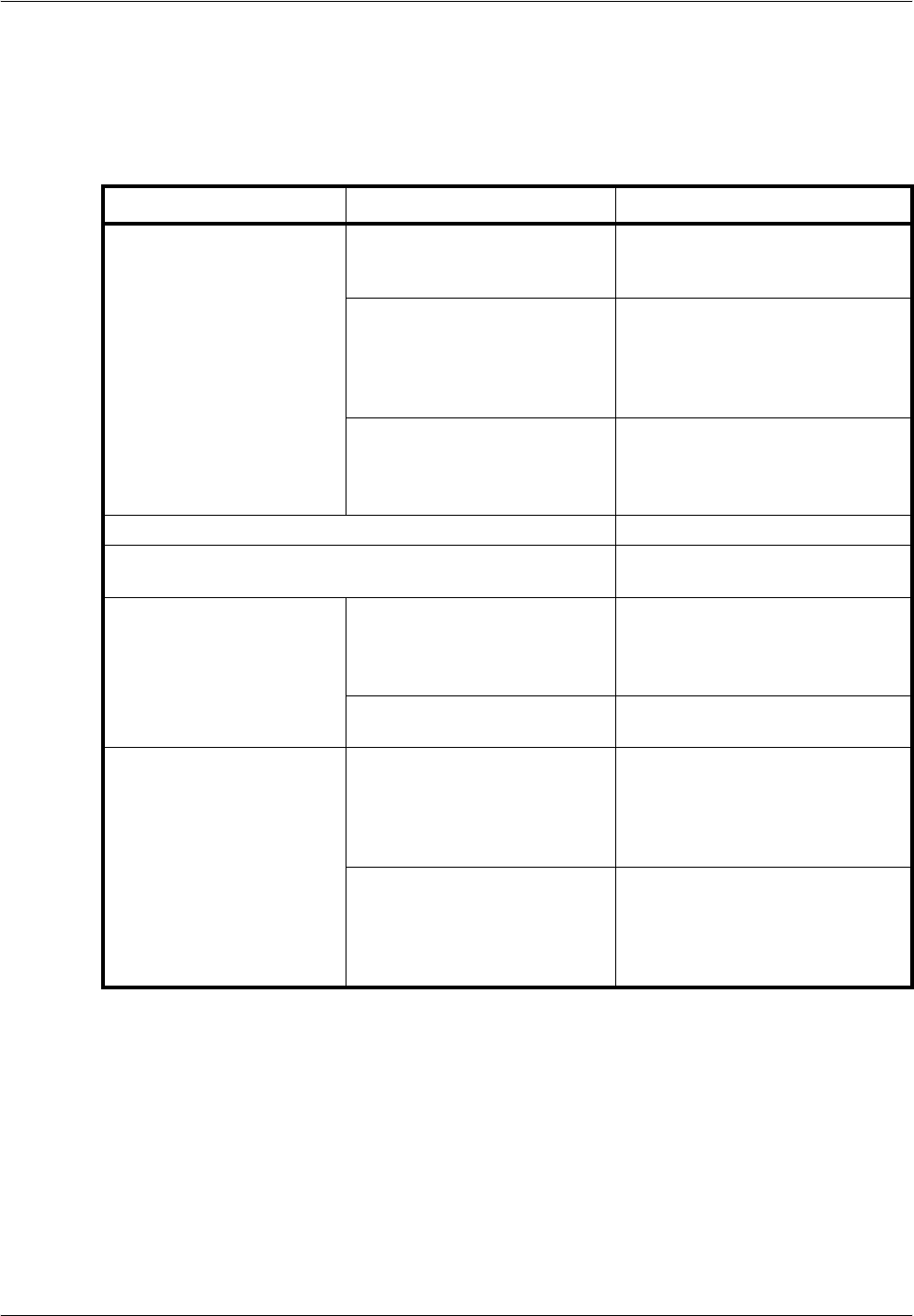
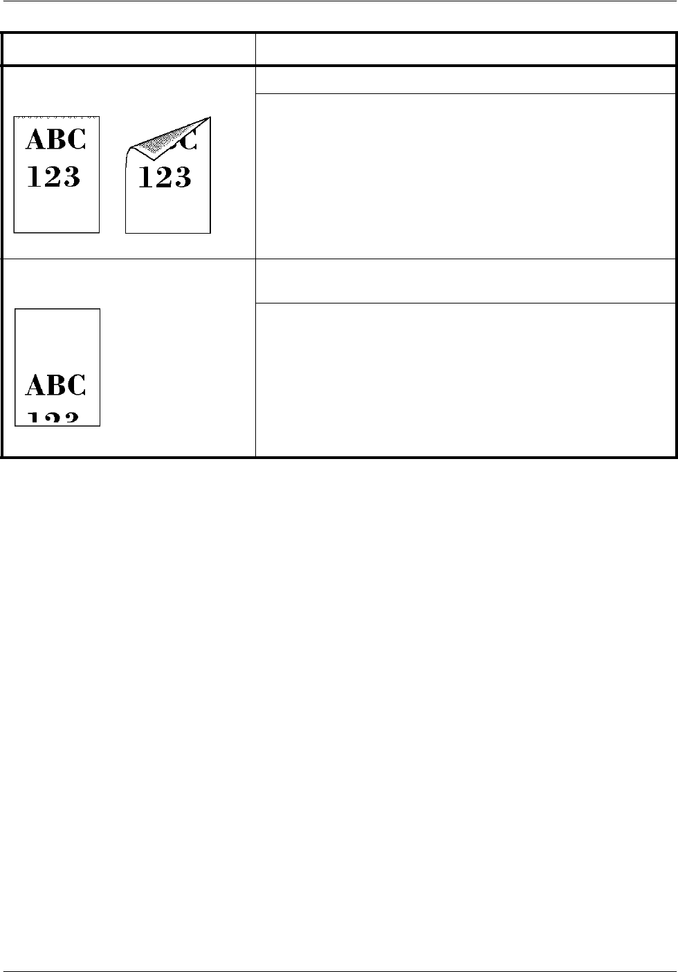
Printed Results Corrective Action
Completely blank printout Verify that the application software is being used correctly. Even if
the problem is not solved, contact your service technician.
Full single-color printout Contact your service technician.
Single-color printout with unwanted
additional colort Contact your service technician.
Troubleshooting
OPERATION GUIDE 5-5
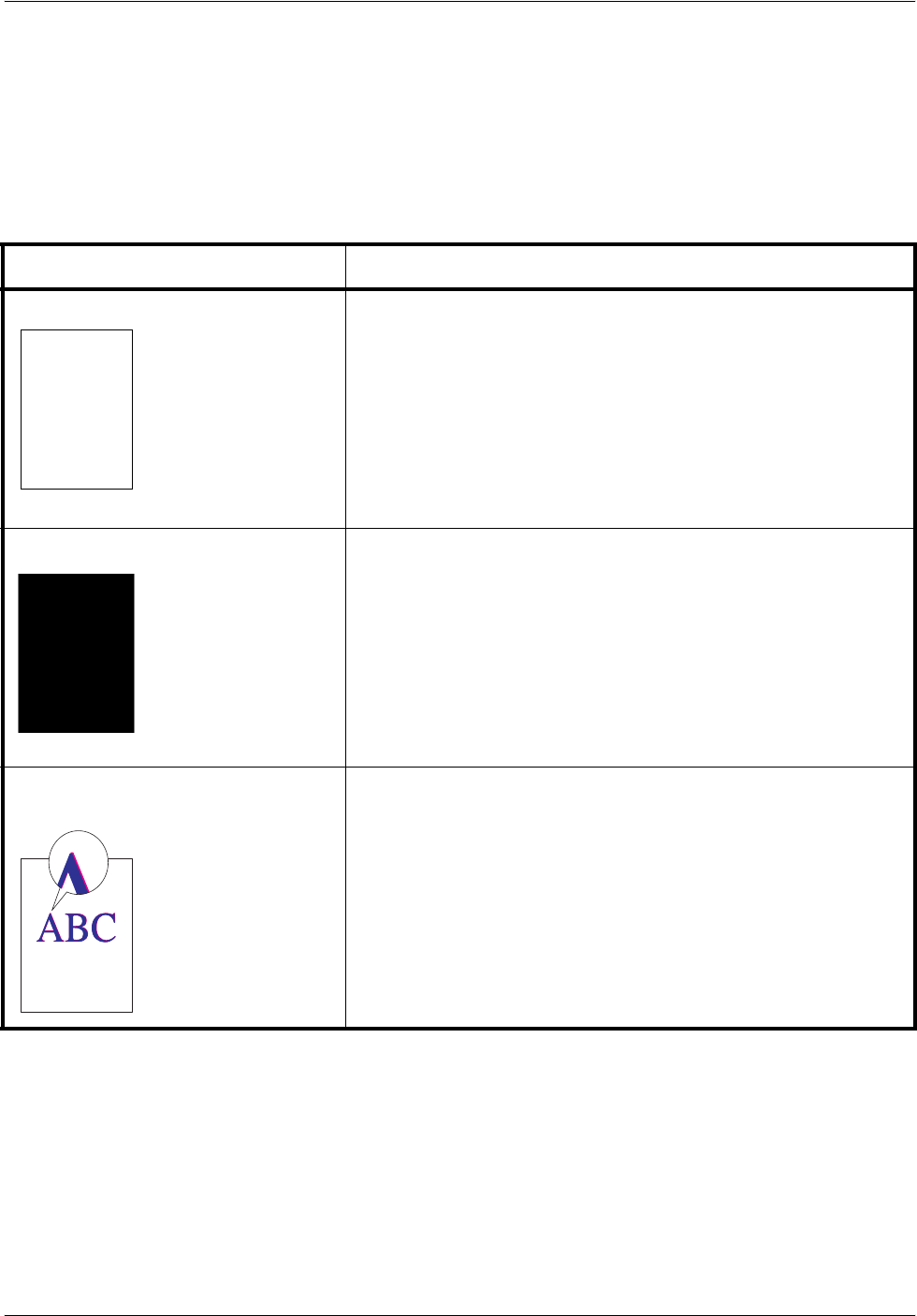
Vertical streaks Refresh drum.
Perform the following procedures on the operation panel and try
cleaning the drum surface using the printer's built-in cleaning
system.
1Press and hold [GO] and [Cancel] for at least 3 seconds
when the Ready indicator lights up. All indicators flash slowly.
2Press [Cancel]. The Attention, Data, and Ready indicators
flash slowly, and toner indicator (K) lights up.
3Press [GO]. Drum refreshing starts. The toner indicators light
and flash in order of K, C, M, and Y.
Drum refleshing stops after approx.4 minutes, and the Ready
indicator lights up.
If the corrective action above will not solve the problem, contact
your service technician.
Faint or blurred printing Make sure the paper type setting is for the correct the paper being
used.
Try adjusting the color control settings using the printer driver.
Check the EcoPrint setting.
When the PDL setting is KPDL and the EcoPrint setting is 75% or
50% in the printer driver, turn EcoPrint Off.
Refresh drum.
Perform the following procedures on the operation panel and try
cleaning the drum surface using the printer's built-in cleaning
system.
1Press and hold [GO] and [Cancel] for at least 3 seconds
when the Ready indicator lights up. All indicators flash slowly.
2Press [Cancel]. The Attention, Data, and Ready indicators
flash slowly, and toner indicator (K) lights up.
3Press [GO]. Drum refreshing starts. The toner indicators light
and flash in order of K, C, M, and Y.
Drum refleshing stops after approx.4 minutes, and the Ready
indicator lights up.
If color difference occurs in the printouts, contact a service
technician.
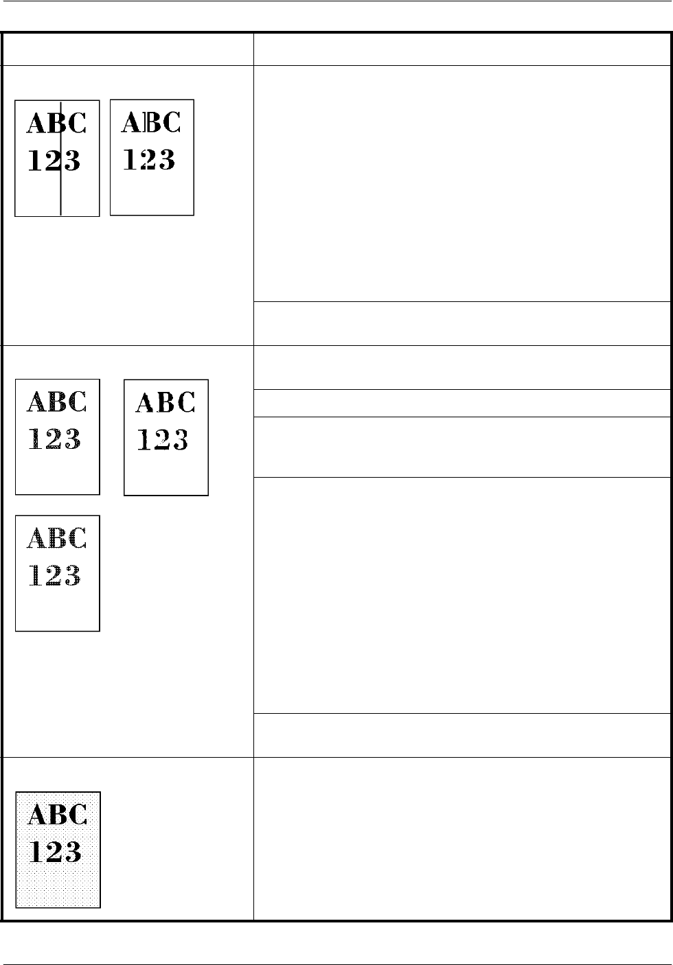
Gray background If the toner indicator (K/C/M/Y) flashes, install a new toner kit. To
replace the toner container, refer to Toner Container
Replacement on page 4-3. If color difference occurs in the
printouts, contact a service technician.
Printed Results Corrective Action
Troubleshooting
5-6 OPERATION GUIDE
Dirt on the top edge or back of the
paper Clean the registration roller.
Check the transfer roller.
If the transfer roller is dirty with toner, try printing several pages.
Printing incomplete or out of
position Check that the printing settings are correct in the application
software and the printer driver.
Refer to Tips on page 5-2.
Printed Results Corrective Action
Troubleshooting
OPERATION GUIDE 5-7
Clearing Paper Jams
If paper jams in the paper transport system, or no paper sheets are fed at
all, the printer automatically goes offline, and the attention indicator will
flash rapidly. KM-NET for Clients or COMMAND CENTER can indicate the
location of the paper jam (the component where the paper jam has
occurred). Remove the paper jam. After removing the paper jam, the
printer will resume printing.
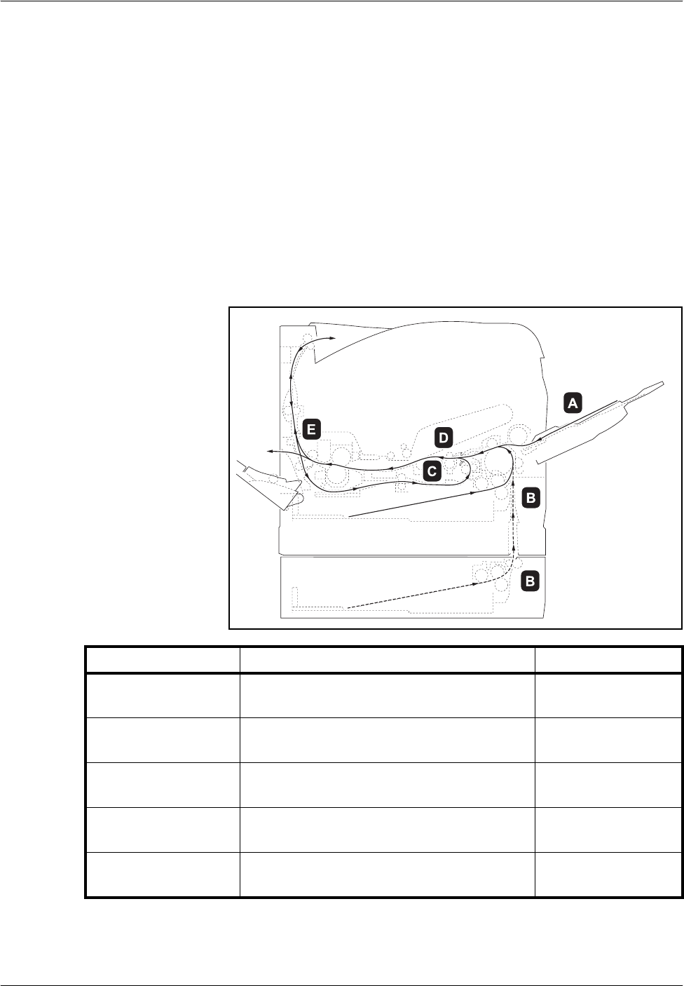
Possible Paper Jam Locations
The figure below shows the printer’s paper paths including the optional
devices. The locations where paper jams might occur are also shown here,
with each location explained in the table below. Paper jams can occur in
more than one component on the paper paths.
Paper Feeder
PF-330
MP Tray
Paper Cassette
Paper jam location Description Reference page
APaper jam at the MP tray. page 5-9
BPaper jam at the paper cassette. The
cassette number can be 1. page 5-9
CPaper jam inside the duplex section. page 5-10
DPaper jam inside the paper transfer unit. page 5-11
EPaper jam inside the fuser unit. page 5-12

Troubleshooting
5-8 OPERATION GUIDE
General considerations for clearing jams
Bear in mind the following considerations when attempting paper jam
removal:
CAUTION: When pulling the paper, pull it gently so as not to tear it. Torn
pieces of paper are difficult to remove and may be easily overlooked,
deterring the paper jam recovery.
• If paper jams occur frequently, try using a different type of paper,
replace the paper with paper from another ream, or flip the paper stack
over. The printer may have problems if paper jams recur after the
paper is replaced.
• Whether or not the jammed pages are reproduced normally after
printing is resumed, depends on the location of the paper jam.
Troubleshooting
OPERATION GUIDE 5-9
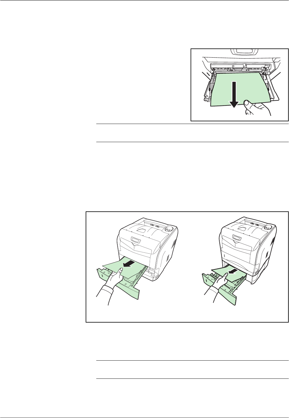
MP Tray
Paper is jammed at the MP tray. Remove the jammed paper using the
procedure given below.
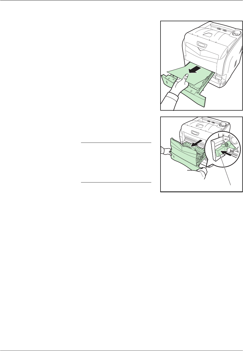
1Remove the paper jammed at the
MP tray.
IMPORTANT: Do not try to remove paper that has already been partially
fed. Proceed to Paper Transfer Unit on page 5-11.
2Open and close the front cover to clear the error and the attention indicator
will stop flashing.
Paper Cassette/Paper Feeder
1Pull out the paper cassette or optional paper feeder.
2Remove any partially fed paper.
Check to see if paper is loaded correctly. If not, reload the paper.
3Push the paper cassette back in securely. The printer resumes printing.
IMPORTANT: If the jammed paper appears inside of the printer, proceed
to Paper Transfer Unit on page 5-11.
Paper Cassette Paper Feeder
Troubleshooting
5-10 OPERATION GUIDE
Duplexer
Paper is jammed in the duplex section. Remove the jammed paper using
the procedure given below.
1Pull the paper cassette all the way out of the printer.
2Open the duplexer’s cover and
remove any jammed paper.
3Insert the paper cassette into the slot in the printer. The printer resumes
printing.
Troubleshooting
OPERATION GUIDE 5-11
Paper Transfer Unit
1Pull out the paper cassette and
remove the jammed paper.
2While pulling the green release
lever, pull out the paper transfer
unit.
NOTE: When you pull out the
transfer unit together with the
paper casette, a bottom plate
of the paper casette may lift.
Push the bottom plate down
until it locks.
Release Lever
Troubleshooting
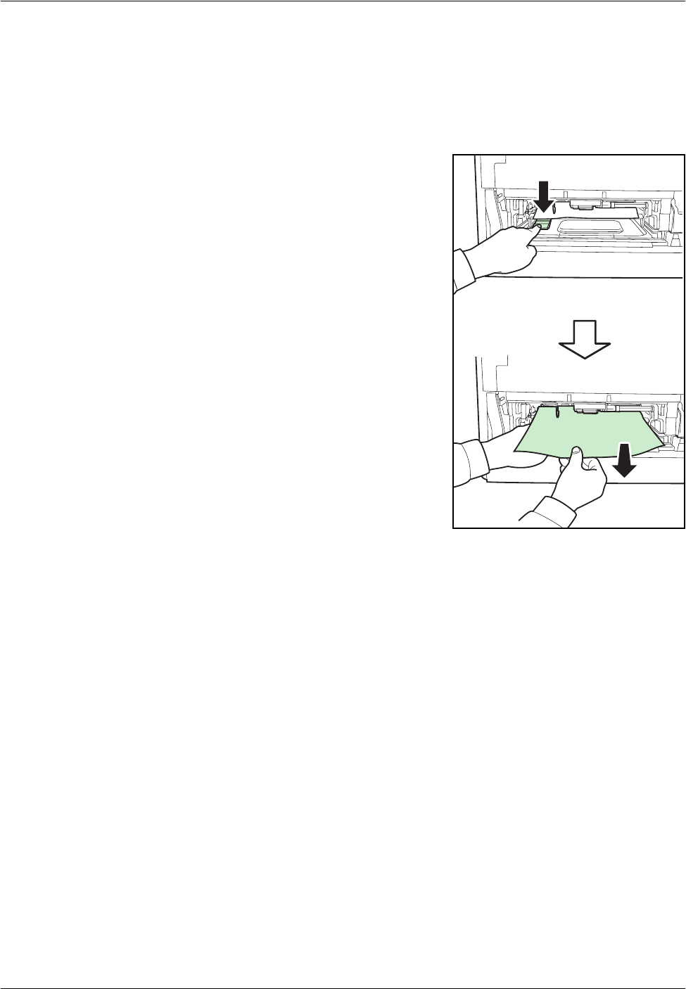
5-12 OPERATION GUIDE
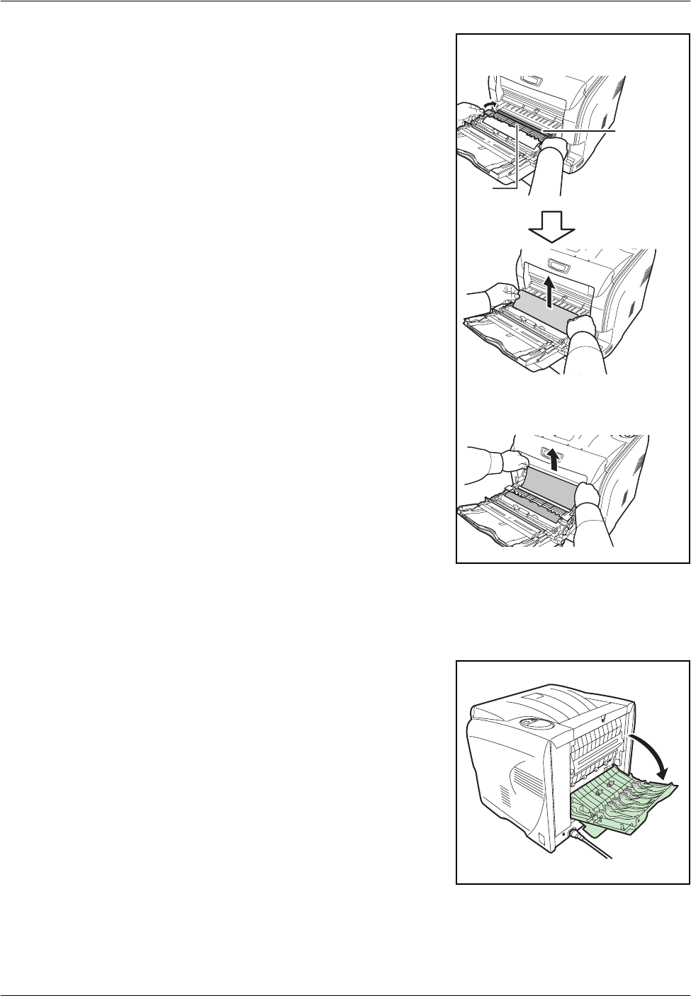
3If paper is jammed as shown in A,
remove the paper by lifting the
feed cover and pulling the paper
from the center of it. If paper is
jammed as shown in B, remove the
paper by pulling the edge of it.
4Push the paper transfer unit back in completely. The printer warms up and
resumes printing.
Fuser Unit
1If paper is not completely ejected
into the output tray, open the rear
cover.
(A)
(B)
Registration
roller
Feed
cover
Troubleshooting
OPERATION GUIDE 5-13
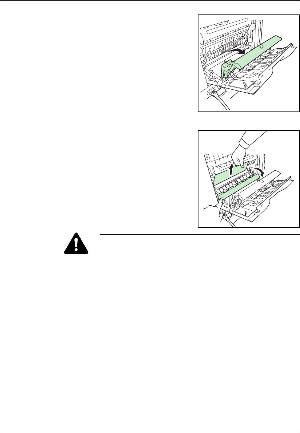
2Pull the rear paper path and open
it.
3Open the fuser cover and remove
the jammed paper by pulling it out.
CAUTION: The fuser unit inside the printer is hot. Do not touch it, as it
may result in burn injury.
4Close the fuser cover, rear paper path, rear cover, and rear subcover. The
printer warms up and resumes printing.

Troubleshooting
5-14 OPERATION GUIDE

OPERATION GUIDE 6-1
6 Options
This chapter contains explanations on the following topics:
• General Information...................................................... 6-2
• Expansion Memory Modules........................................ 6-3
• PF-330 Paper Feeder................................................... 6-6
For availability of the options, consult a service technician.
Options
6-2 OPERATION GUIDE
General Information
The printers have the following options available to satisfy your printing
requirements. For instructions on installing individual options, refer to the
documentation included with the option. Some options are explained in the
following sections..
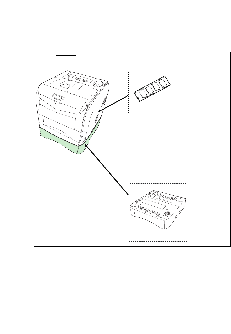
Printer
Expansion Memory
(DIMM 64/128/256/512MB)
Paper Feeder PF-330
Options
OPERATION GUIDE 6-3
Expansion Memory Modules
To expand the printer memory for more complex print jobs and faster print
speed, you can plug in optional memory module (dual in line memory
module) in the memory slot provided on the printer main controller board.
You can select additional memory module from 64, 128, 256 or 512MB.
The maximum memory size is 576MB.
NOTE: The expansion memory should only be installed by your service
technician. We shall not be liable for any damages caused by improper
installation of expansion memory.
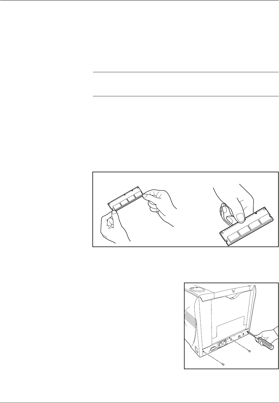
Precautions for handling the printer's main controller board and memory
module.
To protect electronic parts, discharge static electricity from your body by
touching a water pipe (faucet) or other large metal object before handling
the memory module. Or, wear an antistatic wrist strap, if possible, when
you install the memory module.
Always hold the main controller board or a memory module by its edges as
shown below to avoid damaging electronic parts.
Installing the Memory Module
1Turn off the printer and disconnect the power cord and printer cable.
2Remove three screws from the
rear of the printer.
YES NO
Options
6-4 OPERATION GUIDE
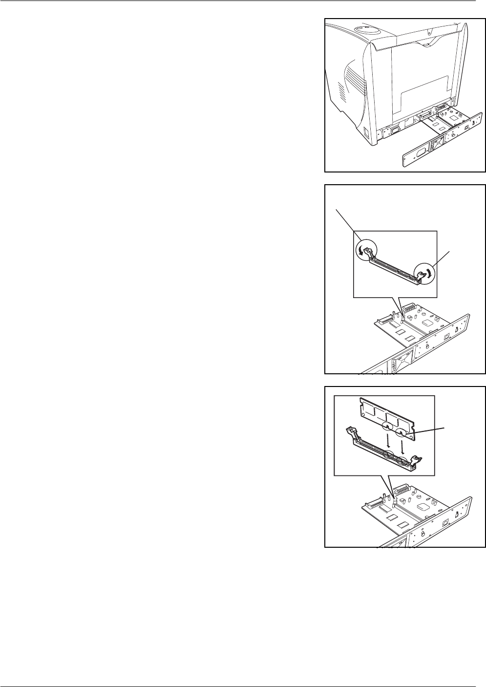
3Pull out the main controller board
gently.
4Push out the clamps on both ends
of the memory socket on the main
controller board.
5Remove the memory module from
its package. Aligning the cutouts of
the memory module with the
matching keys of the socket,
carefully plug the memory module
into the memory socket until it
clicks in place.
6Push the two socket clamps to secure the memory module.
7After you finish installing the memory module, reinstall the main controller
board and fasten it with screws.
Clamp
Clamp
Cutouts

Options
OPERATION GUIDE 6-5
Removing a Memory Module
To remove a memory module, remove three screws from the rear of the
printer, pull out the main controller board gently, then carefully push out the
two socket clamps. Ease the memory module out of the socket to remove.
Testing the expanded memory
To verify that the memory module is working properly, test it by printing a
status page.
Options
6-6 OPERATION GUIDE
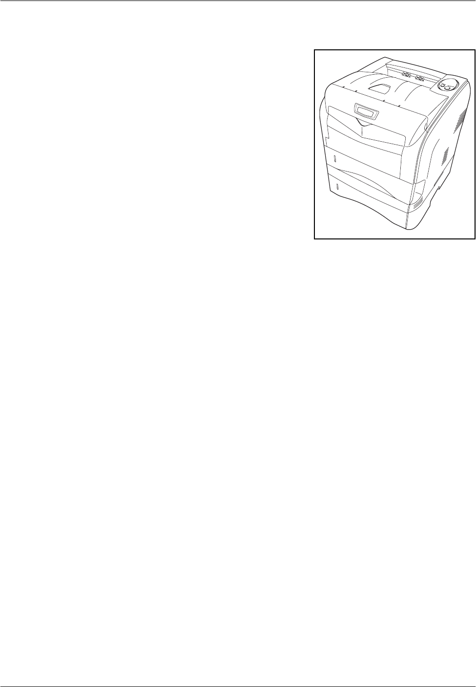
PF-330 Paper Feeder
Holds approximately 250 sheets of
A5 to A4/Letter and Legal size
paper. Up to one paper feeder can
be attached to the bottom of the
printer.
The PF-330 paper feeder allows
you to add one more paper
cassette to the bottom of the printer
for continuous feeding of a large
volume of paper. Each paper
cassette can hold up to
approximately 250 sheets of ISO
A4, ISO A5, JIS B5, Letter, or Legal
size (80g/m²) paper. This feeder is
attached at the bottom of the
printer as shown on the right.

OPERATION GUIDE 7-1
7 Specifications
NOTE: Specifications are subject to change without notice.
Item Description
Type Desktop
Printing Method Electrostatic four color (CMYK) printing using Advanced
Beam Array
Paper Weight
- Cassette
- MP Tray
60 to 105 g/m2 (Duplex: 60 to 90 g/m2)
80 to 220 g/m2
Paper Type
- Cassette
- MP Tray
Plain, Preprinted, Bond, Recycled, Rough, Letterhead,
Color, Prepunched, High quality, and Custom
Plain, Transparency, Preprinted, Labels, Bond, Recycled,
Vellum, Rough, Letterhead, Color, Prepunched, Envelope,
Cardstock, Coated, Thick, High quality, and Custom
Paper Size
- Cassette
- MP Tray
Legal, Oficio II, Letter-R, Folio, ISO A4-R, JIS B5-R, ISO
A5, 16K
Executive, Statement, Envelope #10, Envelope #9,
Envelope Monarch, Envelope #6, Envelope C5, Envelope
DL, Legal, Oficio II, Letter-R, Folio, ISO A4-R, JIS B5-R,
ISO B5-R, ISO A5, JIS B6, ISO A6, Hagaki, Ofuku-Hagaki,
Youkei 2, Youkei 4, 16K, Custom (70 × 148 to 216 ×
356mm (2-13/16 × 5-13/16 to 8-1/2 × 14 inches))
Printing Speed
- Simplex
- Duplex
Monochrome Color
A4/Letter : 24 ppm 6 ppm
A5 : 12 ppm 6 ppm
A4/Letter: 4.8 ppm 3 ppm
A5: 4 ppm 3 ppm
First Print Out (At polygon motor steady-state) 10 seconds or less (monochrome)
20 seconds or less (color)
Warm-up Time (22°C, 60%RH)
- Power on
- Sleep
45 seconds or less
45 seconds or less
Resolution 600dpi

Specifications
7-2 OPERATION GUIDE
Paper Capacity
- Cassette
- MP Tray
250 sheets (80g/m2)
50 sheets (80g/m2)
Output Tray Capacity
- Top Tray 100 sheets (80g/m2)
Monthly Duty
- Average
- Maximum
1,000 pages
30,000 pages
Operation Environment Temperature: 10 to 32.5 °C (50 to 90.5°F)
Relative Humidity: 15 to 80%
Altitude: 2,500m (8202 feet) maximum
Brightness: 1,500lux maximum
Dimensions (W × D × H) 415 × 415 × 360mm
16 11/32 × 16 11/32 × 14 11/64"
Weight (without toner container and waste
toner box) 26kg/57.3 lb
Controller PowerPC 440 400MHz
Supported OS Microsoft Windows 95/98/Me/2000/XP
Microsoft Windows NT4.0
Microsoft Windows Server 2003
Apple Macintosh OS 8
Apple Macintosh OS 9
Apple Macintosh OS X
Interface
- Standard Hi-Speed USB for printer connections: 1
Network: 1, 10BASE-T/100BASE-TX
Memory
- Standard
- Maximum 64MB
576MB
Option Paper feeder (PF-330)
Power Source 120 V AC, 60 Hz, 8.0A/220 to 240 V AC, 50 HZ, 4.5 A
Power Consumption Maximum: 1000 W
During printing: 311 W or less (313 W or less, with PF-330)
During standby: 71 W or less
During sleep mode: 6 W or less (7 W or less, with PF-330)
Operating noise (in accordance with EN
ISO7779 [Bystander Position, sound pressure
level at the front])
During printing: LpA = 55dB (A)
During standby: LpA = 40dB (A)
During sleep mode: immeasurably low
Item Description

OPERATION GUIDE Index-1
Index
A
Adhesive label 2-8
Attention indicator 1-5
operation panel 1-4
C
Cancel key 1-6
operation panel 1-4
Casette
paper size 2-4
Cassette
basis weight 2-5
paper size 7-1
paper type 7-1
paper weight 7-1
Caution labels Legal and Safety-xvi
CF card 6-6
Changing or verifying the network settings
3-4
Cleaning
neighboring part of the toner container
4-9
paper transfer unit 4-10
Clearing paper jams
Duplexer 5-10
fuser unit 5-12
MP tray 5-9
paper cassette 5-9
paper feeder 5-9
paper transfer unit 5-11
Colored paper 2-10
COMMAND CENTER 3-4
Components
at the front of the printer 1-2
at the left of the printer 1-2
at the rear of the printer 1-3
internal 1-2
Configuring printer settings 3-7
KM-NET for Clients 3-7
Conventions Legal and Safety-xxiii
D
Data indicator 1-5
operation panel 1-4
Duplexer
clearing paper jams 5-10
E
Envelope 2-10
Expanded memory
verifying 6-5
F
Face up tray
components 1-3
Fuser unit
change the thickness of paper 2-21
clearing paper jams 5-12
G
GO key 1-6
operation panel 1-4
H
Handling
Main controller board 6-3
Memory module 6-3
I
Indicator
At error 1-5
Indicators
Ready, Data, Attention, Toner 1-5
K
Key
At error 1-6

Index-2 OPERATION GUIDE
Cancel 1-6
GO 1-6
Keys
GO, Cancel 1-6
KM-NET for Clients
configuring printer settings 3-7
L
Label 2-8
Left cover
components 1-2
Loading Paper
Cassette 2-13
MP (Multi-Purpose) tray 2-17
Loading software 3-6
Loading thick paper and envelopes
MP (Multi-purpose) tray 2-19
Lock lever 4-5
M
Machine parts 1-1
Main controller board
expanding memory 6-3
Maintenance
Toner container replacement, cleaning
4-1
Memory
expanding memory 6-3
installing memory modules 6-3
Memory module
Removing 6-5
Message display
for replacing toner containers 4-3
Moving the printer 4-12
MP Tray
paper type 7-1
MP tray
basis weight 2-5
clearing paper jams 5-9
components 1-2
loading paper 2-17
loading thick paper and envelopes 2-19
minimum and maximum paper sizes 2-3
paper size 7-1
paper sizes 2-4
paper specifications 2-2
paper type 2-12
paper weight 7-1
N
Network indicators
components 1-3
Network interface connector
components 1-3
non-use of printer for long period of time 4-12
Number of copies
entering the number of prints required 3-8
O
Offline 1-5
Online 1-5
Operation panel
components 1-2
indicators, keys, overview 1-4
refreshing drum 5-5
Options 6-2
P
Paper
general guidelines 2-2
loading 2-13
minimum and maximum sizes 2-3
Paper cassette
clearing paper jam 5-11
clearing paper jams 5-9
components 1-2
loading paper 2-13
minimum and maximum page sizes 2-3
Paper feeder
clearing paper jams 5-9
diagrammed 6-6
PF-330 6-6
Paper gauge
loading paper into the cassette 2-16
Paper Input
Specifications 2-2
Paper jam 1-5
general considerations 5-8
messages and corrective actions,
diagrammed 5-11
possible locations, diagrammed 5-7

OPERATION GUIDE Index-3
Paper jams
clearing 5-7
Paper length guide
loading paper 2-14
Paper sizes
MP tray, Casette 2-4
Paper Specifications 2-2
Paper stopper
components 1-2
Paper transfer unit
changing the thickness of paper 2-19,
4-10, 5-11
cleaning 4-10
Paper type 2-12
Paper weight 2-5
Parallel interface
connector, location 1-3
PF 6-6
PF-330
paper feeder(option) 6-6
Postcard 2-9
Power cord connector
components 1-3
Power switch
components 1-3
Precautions for use Legal and Safety-xix
Preprinted paper 2-11
Printer driver
configuring the printer settings 3-7
EcoPrint setting 5-5
loading software 3-6
Printing
from application software 3-8
status page 1-6
Printing problems
print quality problems, blank printing, etc.
5-4
table of general guidelines 5-2
Printing service status page 1-6
Prolonged non-use 4-12
R
Ready indicator 1-5
operation panel 1-4
Rear cover
components 1-3
Rear subcover
components 1-3
Recycled paper 2-11
Removing a memory module 6-5
Resolution
specifications 7-1
Resolving IP address
COMMAND CENTER 3-4
S
Selecting the right paper 2-4
Service status page
how to print 1-6
Sleep mode 1-5
Special paper 2-7
Specifications
Paper 2-2
Starter container
toner container 4-3
Status page 5-2
how to print 1-6
T
Testing the expanded memory 6-5
Thick paper 2-10
Toner container
components 1-2
how to replace 4-4
Toner containers
replacement 4-3
replacement, indicators 4-3
service life 4-3
Toner indicator 1-5
operation panel 1-4
Toner kit
toner container 4-3
Top cover
components 1-2
Top tray
components 1-2
Transfer roller 4-11
Transparency 2-7
Troubleshooting 5-1

Index-4 OPERATION GUIDE
U
USB interface connector
components 1-3
W
Waste toner box
components 1-2
how to replace 4-7
Width guides
loading paper 2-14
Wiper cloth
cleaning registration roller 4-11

A1
is a trademark of Kyocera Corporation

Rev. 1.0 2006.9
Printed in China 302GJ56010