Koden Electronics RB718A Marine Radar RA54 User Manual OME RA5354 1of4
Koden Electronics Co., Ltd Marine Radar RA54 OME RA5354 1of4
UserManual.wiki
>
Koden Electronics
>
RB718A User Manual
>
Manual1of4
Contents
1.
Manual1of4
2.
Manual2of4
3.
Manual3of4
4.
Manual4of4
Manual1of4
Navigation menu
Upload a User Manual
Namespaces
Wiki Guide
HTML
PDF
Info
Views
User Manual
Discussion / Help
Navigation
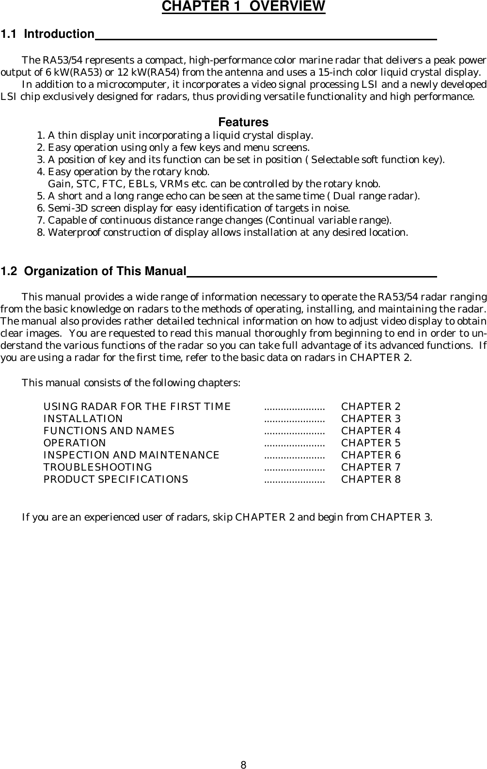
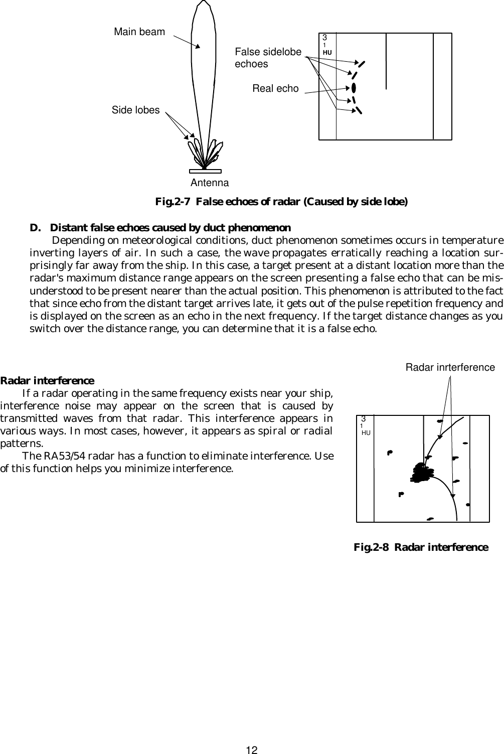
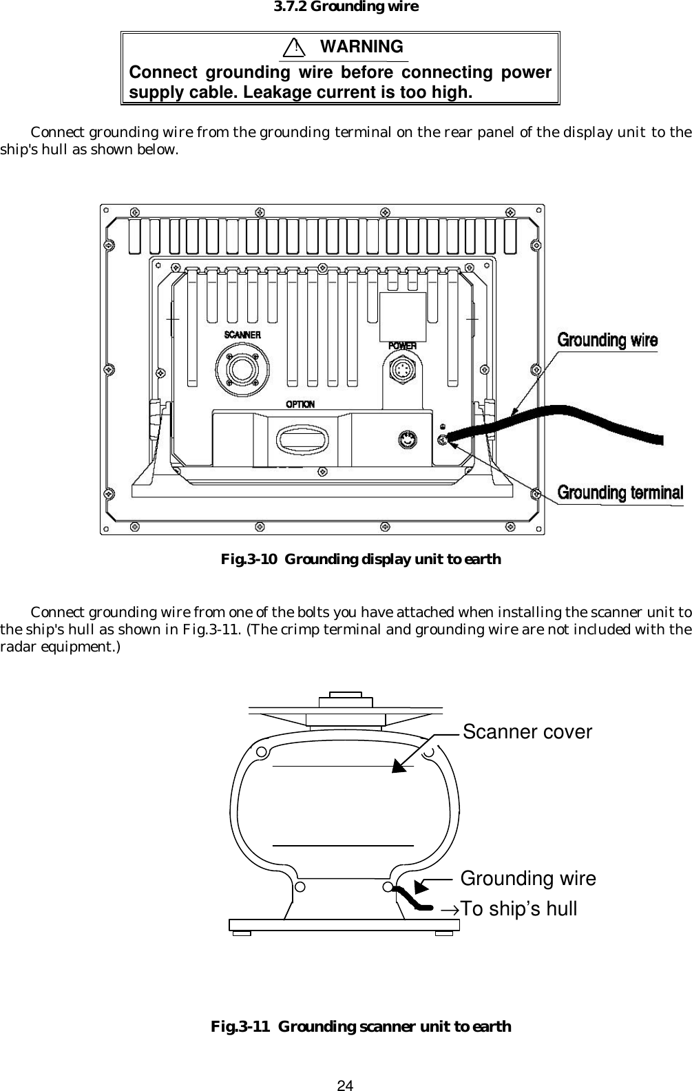
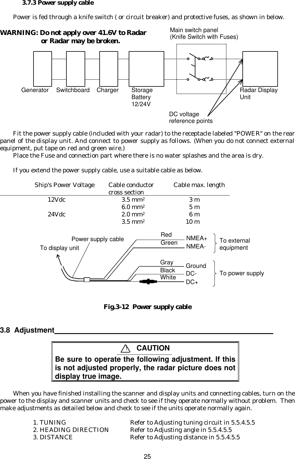
![193.3.3 Shifting away from obstacles 1. Shifting from keel line By shifting the scanner position from the keel line to the starboard side of the ship, it is possible to move shadow zones to the port side which makes it possible to keep vision clear in the bow direction. The distance to be shifted can be obtained by calculation depending on the distance from the scanner to obstacles using the following equation: Ls=0.4R+D/2 [m] (when R<15m) Ls=0.025R+D/2 [m] (when R>=15m) where Ls = distance to be shifted from keel line D = diameter of obstacle on keel line R = distance from scanner to obstacle Fig.3-1 Shifting from keel line 2. Obtaining sufficient dip angle Raise the scanner position so that there is a sufficient dip angle θ available between the line of sight from the scanner to the obstacle and the horizontal line. By raising the dip angle above 5°, it is possible to prevent mid- and long-distance shadow zones. The radar cannot detect objects below the line of sight. Fig.3-2 Obtaining sufficient dip angle Ls R D Scanner Unit Obstacle Keel line Horizontal line Line of sight θ](https://usermanual.wiki/Koden-Electronics/RB718A.Manual1of4/User-Guide-166979-Page-19.png)