Koden Electronics RB718A Marine Radar RA54 User Manual OME RA5354 1of4
Koden Electronics Co., Ltd Marine Radar RA54 OME RA5354 1of4
Contents
- 1. Manual1of4
- 2. Manual2of4
- 3. Manual3of4
- 4. Manual4of4
Manual1of4
1
To prevent the risk of personal injury or damage to the equipment, the following safety symbols are
used to indicate safety-related information. Insure that you clearly understand the meanings of the
symbols BEFORE using the equipment.
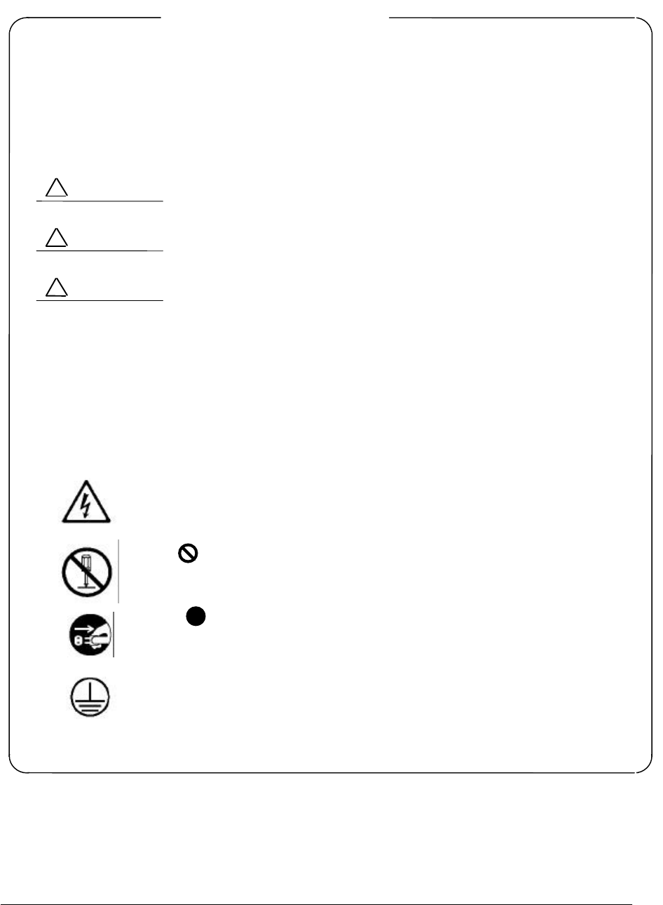
Symbols Used in Manual
This indicates a very dangerous procedure that could result in serious
injury or death if not performed properly.
This indicates a hazardous procedure that could result in serious injury
or death if not performed properly.
This indicates a hazardous procedure or danger that could result in
light-to-severe injury, or that might damage the equipment, if proper
precautions are not taken.
Safety Symbols Used on Equipment
The following safety symbols are used inside or on the equipment near operation locations to
provide information about safety items and operation precautions. Insure that you clearly under-
stand the meanings of the symbols and take the necessary precautions BEFORE using the
equipment.
This indicates high voltages with a risk of serious electric shock if the part is
touched. NEVER touch the part with bare hands, etc.
The symbol prohibits the operation shown inside the symbol. (The example
in the left prohibits disassembly.)
The symbol indicates that the operation inside the symbol is potentially
hazardous. (The example on the left indicates that the plug should be held when
disconnecting it from the AC outlet.)
This indicates the ground (earth) terminal. If the equipment cannot be grounded
via the power cord, connect this terminal to ground. There is a risk of serious
electric shock if the equipment is not grounded.
RA53/RA54
Marine Radar
Instruction Manual
1st Jun. 2001 (1st Edition)
Document: E-A53/54-1
Safety Symbols
DANGER
!
WARNING
!
CAUTION
!
2
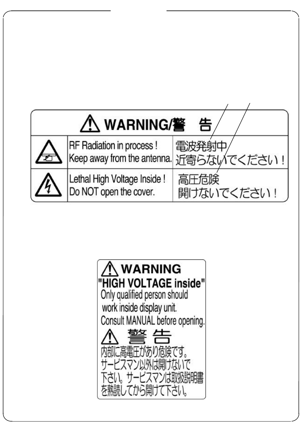
WARNING and CAUTION for Scanner Unit and Antenna ;
1. Do not approach the antenna while it is transmitting.
In addition, at inspection never look into the wave guide during transmission.
Distance at which RF power density level to become 100 W/m2: 2 m
Distance at which RF power density level to become 10 W/m2: 6 m
2. There is a risk of receiving electric shock if these parts are touched by accident. Only
qualified personnel should remove covers on these parts.
WARNING for Display Unit ;
There is a risk of receiving electric shock if these parts are touched by accident.
Only qualified personnel should remove covers on these parts.
For Safety
1.
2.
3
Installation
Only qualified personnel should install the radar system in order to make sure proper radar performance
and operation.
To Customers
* To always use this equipment at its best condition, we recommend observing the operation and main-
tenance procedures in this manual from time to time. Further, try to operate the radar in good visibility
condition to make comparison between visual impression and the radar picture presentation of the
situation you are in. By doing this, you will be able to gain practical knowledge in interpreting the radar
picture as well as the false echoes and blind sectors caused by the masts or funnel of the ship. Note that
this equipment should only be used as a navigational aid and ship’s crew must make final decision on
ship’s maneuvering.
* In case of functional failure, immediately turn off the radar and switch off the ship’s main power supply at
the distribution switchboard. Inform your local service agent of the faulty situation to detail, where pos-
sible.
* This instrument uses crystal oscillators and a LCD backlight lamp, which are vulnerable to mechanical
shock. Take utmost care when handling these items
* The mercury (Hg) is used in the LCD backlight lamp. When you attempt to discard your radar, observe
the local code of practice for deposit.
4
Contents
For safety
CHAPTER 1 OVERVIEW.........................................................................8
1.1 Introduction............................................................................................................8
1.2 Organization of This Manual................................................................................8
CHAPTER 2 USING RADAR FOR THE FIRST TIME..........................9
2.1 What is a radar ?....................................................................................................9
2.2 Characteristics of Radar Wave .............................................................................10
2.3 Terms Specific to Radars.......................................................................................13
CHAPTER 3 INSTALLATION.................................................................16
3.1 Checking Contents of Your Package.....................................................................16
3.2 Checking Power Supply Voltage...........................................................................17
3.2.1 Power Supply Requirement .............................................................................17
3.2.2 Fuse Replacement.............................................................................................17
3.3 Determining Place of Installation.........................................................................18
3.3.1 Scanner unit......................................................................................................18
3.3.2 Display unit.......................................................................................................18
3.3.3 Shifting away from obstacles ...........................................................................19
3.4 Installing Scanner Unit.........................................................................................20
3.5 Installing Antenna Unit........................................................................................21
3.6 Installing Display Unit..........................................................................................22
3.7 Connecting Cables .................................................................................................22
3.7.1 Interconnecting cable........................................................................................22
3.7.2 Grounding wire.................................................................................................24
3.7.3 Power supply cable ...........................................................................................25
3.8 Adjustment.............................................................................................................25
3.9 Connecting External Equipment to Display Unit ...............................................26
3.10 Countermeasure for Electromagnetic Interference...........................................26
3.11 When Discarding Your Radar.............................................................................27
CHAPTER 4 FUNCTIONS AND NAMES...............................................28
4.1 Key layout ..............................................................................................................28
4.2 Rear panel..............................................................................................................29
4.3 Radar screen (Single screen).................................................................................29
4.4 Radar screen (Dual screen)...................................................................................30
4.5 Radar screen (All PPI screen)...............................................................................30
4.6 Radar screen (All PPI/PPI screen)........................................................................31
4.7 Navigation screen ..................................................................................................31
CHAPTER 5 OPERATION.......................................................................32
Basic operation of Radar .............................................................................................32
5.1 Turning ON and OFF the radar ...........................................................................32
5.2 Adjusting brilliance of screen and key-backlight.................................................32
5.3 Basic Operations....................................................................................................33
5.3.1 Powering On and Off........................................................................................33
5.3.2 Transmitting .....................................................................................................33
5.3.3 Adjusting the brilliance of the screen and key-backlight...............................34
5.3.4 Changing the range scale (RANGE UP, RANGE DOWN).............................34
5.3.5 Automatic adjustment (AUTO)........................................................................34
5.3.6 Sensitivity adjustment (GAIN) ........................................................................ 35
5.3.7 Removing the sea clutter (STC) ....................................................................... 35
5.3.8 Removing the rain and snow clutter (FTC)..................................................... 36
5.3.9 Man Over Board (MOB).................................................................................... 36
5.3.10 Acquisition of a target (ACQ)............................................................................... 36
5.3.11 Select target number (TGT NUM)...................................................................... . 36
5
5.4 Functions of Soft Keys...........................................................................................37
5.4.1 Bearing measurement (EBL1).........................................................................37
5.4.2 Bearing measurement (EBL2).........................................................................37
5.4.3 Distance measurement (VRM1).......................................................................37
5.4.4 Distance measurement (VRM2).......................................................................38
5.4.5 Measuring the angle between two points (FL EBL2).....................................38
5.4.6 Measuring the distance between two points (FL VRM2)...............................38
5.4.7 Changing the group of Soft Keys(NEXT)........................................................38
5.4.8 Erasing the heading marker temporarily (HDG OFF)...................................39
5.4.9 Using the parallel cursor (///CSR)....................................................................39
5.4.10 Establishment of the indication of the RANGE RINGS (RINGS)...............39
5.4.11 ON/OFF of variable range function (VAR RNG) ..........................................39
5.4.12 Changing the display modes (MODE)...........................................................39
5.4.13 Guard Zone (GZ).............................................................................................40
5.4.14 Off Center (OFF-C).........................................................................................40
5.4.15 Setting up the SLEEP function(SLEEP).......................................................41
5.4.16 Tuning adjustment (TUNE)...........................................................................41
5.4.17 Echo expansion (ST) .......................................................................................41
5.4.18 Displaying the target track (TRACK)............................................................41
5.4.19 Enlarging the selected areas (ZOOM)...........................................................42
5.4.20 Increasing the sensitivity (S/L)......................................................................42
5.4.21 Switching the screen (SEL WIN)...................................................................42
5.4.22 Changing the screen color (PICTURE)..........................................................43
5.4.23 Change to PPI screen (PPI)............................................................................43
5.4.24 Change to SEMI3D/PPI screen (SEMI3D)....................................................43
5.4.25 Change to PPI/PPI screen (PPI/PPI) .............................................................43
5.4.26 Change to PPI/NAV screen (PPI/NAV) .........................................................44
5.4.27 Change to ALL PPI screen (ALL PPI)...........................................................44
5.4.28 Change to ALL PPI/PPI screen (ALL PPI2)..................................................44
5.4.29 Canceling target tracking (DEL)...................................................................44
5.4.30 Canceling all target tracking (ALL DEL).....................................................44
5.4.31 Data display (DATA)......................................................................................44
5.5 MENU Operation ..................................................................................................46
- List of MENU .........................................................................................................46
5.5.1 Mark Menu........................................................................................................47
5.5.1.1 Bearing measurement (EBL1).....................................................................47
5.5.1.2 Determining the distance (VRM1)...............................................................48
5.5.1.3 Bearing measurement (EBL2).....................................................................48
5.5.1.4 Determining the distance (VRM2)...............................................................48
5.5.1.5 Measuring the distance or angle between two points ( FL EBL2, FL VRM2 )
......................................48
5.5.1.6 Measuring the angle between two points (FL EBL2).................................49
5.5.1.7 Erasing the heading marker temporarily (HDG OFF) ..............................50
5.5.1.8 Using the parallel cursors (///CSR)..............................................................50
5.5.1.9 Displaying the RANGE RINGS (RINGS) ...................................................51
5.5.1.10 Variable range function ( VAR RNG ).......................................................51
5.5.1.11 To output the Cursor (TARGET) position data to external equipment ..52
5.5.1.12 Setting the Distance and Bearing marker to follow the cross cursor
(+MK LINE)........................................52
5.5.2 Nav (Navigation) Menu.....................................................................................52
5.5.2.1 Changing the display mode (MODE) .........................................................53
5.5.2.2 Setting the Guard Zone (GZ) .......................................................................53
5.5.2.3 Shifting the display to a specific direction (OFF-C)...................................54
5.5.2.4 Setting up the SLEEP function(SLEEP).....................................................55
5.5.3 Echo Menu ..........................................................................................................56
5.5.3.1 Sensitivity adjustment (GAIN)....................................................................56
5.5.3.2 Removing the sea clutter (STC)...................................................................57
5.5.3.3 Removing the rain and snow clutter (FTC) ................................................57
5.5.3.4 Adjusting the receiver tuning (TUNE)........................................................57
5.5.3.5 Echo expansion (ST).....................................................................................58
6
5.5.3.6 Displaying the target track (TRACK)..........................................................58
5.5.3.7 Enlarging the selected areas (ZOOM).........................................................59
5.5.3.8 Increasing the sensitivity (S/L)....................................................................59
5.5.4 SETUP Menu....................................................................................................60
5.5.4.1 Selecting and setting up the screen mode (WINDOW) ..............................60
- Available funtions on each screen mode...............................................................61
- Screen modes and Operations................................................................................62
(a) PPI Screen..................................................................................................62
(b) PPI/SEMI3D Screen ..................................................................................62
(c) PPI/PPI Screen...........................................................................................62
- Operation.......................................................................................................63
(d) PPI/NAV Screen.........................................................................................64
(e) ALL PPI Screen..........................................................................................64
(f) ALL PPI/PPI Screen...................................................................................64
(g) MOB Screen ...............................................................................................64
5.5.4.2 Switching screens on PPI/PPI screen (SEL WIN) ......................................65
5.5.4.3 Changing the screen color (PICTURE)........................................................65
5.5.4.4 Fault Diagnosis by Self Check (SYSTEM CHECK)....................................66
5.5.4.5 Changing the content of the setting (CUSTOM) ........................................68
5.5.4.5.1 Changing the settings of the soft keys (KEY ASSIGN)..........................69
5.5.4.5.2 Changing the content of settings 1(PRESET1).......................................71
5.5.4.5.3 Changing the content of settings 2 (PRESET2)......................................73
5.5.4.5.4 Changing the content of priority for NMEA input(NMEA PRESET) ...75
5.5.4.5.5 Changing the content of settings (ADJUSTMENT) ............................... 75
(1) Adjusting the distance (TIMING ADJ).................................................. 75
(2) Adjusting the angle (HEAD ADJ).......................................................... 76
(3) Adjusting the receiver tuning (TUNING CAL)..................................... 76
(4) Adjusting the antenna height (ANTENNA).......................................... 77
(5) Setting the receiver GAIN (GAIN)......................................................... 77
(6) Setting the STC level (STC) ................................................................... 78
5.5.4.5.6 ATA preset (ATA PRESET)...................................................................... 78
5.6 ATA Operation....................................................................................................... 79
5.6.1 ATA Board Specifications.................................................................................. 79
5.6.2 Operating Instructions...................................................................................... 79
5.6.2.1 Outline........................................................................................................ 79
5.6.2.2 Setting ........................................................................................................ 79
5.6.2.3 Operation.................................................................................................... 80
(1) Acquisition of a target..................................................................................... 80
(2) Tracking the target......................................................................................... 80
(3) Canceling target tracking............................................................................... 80
(4) Data display .................................................................................................... 80
(5) ATA indications..................................................................................................... 81
5.6.2.4 Interface ..................................................................................................... 81
(1) Data output..................................................................................................... 81
(2) Log signal input .............................................................................................. 81
CHAPTER 6 MAINTENANCE AND INSPECTION ..............................82
CHAPTER 7 TROUBLESHOOTING.......................................................84
7.1 Fault Diagnosis by Self-check...............................................................................84
7.2 Inspecting Each Part.............................................................................................85
CHAPTER 8 PRODUCT SPECIFICATIONS..........................................86
8.1 General ................................................................................................................... 86
8.2 Scanner Unit .......................................................................................................... 87
8.3 Display Unit ........................................................................................................... 87
8.4 ATA Unit ................................................................................................................ 88
8.5 External Interface.................................................................................................. 89
8.6 Standard set........................................................................................................... 89
8.7 Options.................................................................................................................... 89
7
8.8 External dimensions and weight...........................................................................89
8.9 External connection and function..........................................................................90
APPENDIX
1. RA53 GENERAL SYSTEM DIAGRAM
2. RA54 GENERAL SYSTEM DIAGRAM
3. INTERCONNECTION DIAGRAM 24W159631
4. OUTLINE DRAWING DISPLAY UNIT E43BG11000
5. RA53/54 OUTLINE DRAWING SCANNER UNIT E38BG62000
6. FLUSH MOUNT PROCEDURE E43BG11020
7. INDEX

8
CHAPTER 1 OVERVIEW
1.1 Introduction
The RA53/54 represents a compact, high-performance color marine radar that delivers a peak power
output of 6 kW(RA53) or 12 kW(RA54) from the antenna and uses a 15-inch color liquid crystal display.
In addition to a microcomputer, it incorporates a video signal processing LSI and a newly developed
LSI chip exclusively designed for radars, thus providing versatile functionality and high performance.
Features
1. A thin display unit incorporating a liquid crystal display.
2. Easy operation using only a few keys and menu screens.
3. A position of key and its function can be set in position ( Selectable soft function key).
4. Easy operation by the rotary knob.
Gain, STC, FTC, EBLs, VRMs etc. can be controlled by the rotary knob.
5. A short and a long range echo can be seen at the same time ( Dual range radar).
6. Semi-3D screen display for easy identification of targets in noise.
7. Capable of continuous distance range changes (Continual variable range).
8. Waterproof construction of display allows installation at any desired location.
1.2 Organization of This Manual
This manual provides a wide range of information necessary to operate the RA53/54 radar ranging
from the basic knowledge on radars to the methods of operating, installing, and maintaining the radar.
The manual also provides rather detailed technical information on how to adjust video display to obtain
clear images. You are requested to read this manual thoroughly from beginning to end in order to un-
derstand the various functions of the radar so you can take full advantage of its advanced functions. If
you are using a radar for the first time, refer to the basic data on radars in CHAPTER 2.
This manual consists of the following chapters:
USING RADAR FOR THE FIRST TIME ...................... CHAPTER 2
INSTALLATION ...................... CHAPTER 3
FUNCTIONS AND NAMES ...................... CHAPTER 4
OPERATION ...................... CHAPTER 5
INSPECTION AND MAINTENANCE ...................... CHAPTER 6
TROUBLESHOOTING ...................... CHAPTER 7
PRODUCT SPECIFICATIONS ...................... CHAPTER 8
If you are an experienced user of radars, skip CHAPTER 2 and begin from CHAPTER 3.
9
CHAPTER 2. USING RADAR FOR
THE FIRST TIME
This chapter describes basic information on radars and explains technical terms used in radar op-
eration for those who are using a radar for the first time.
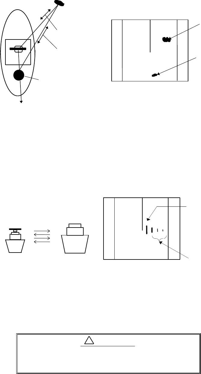
2.1 What is a radar ?
A marine radar is one of the navigation equipment installed on a ship. It emits a radio wave in very
high frequency called a microwave from its antenna and receives the reflected radio wave from objects on
the sea (e.g., other ships, buoys, and lands). The received radio wave is converted into an electric signal
which is displayed on a display screen to indicate the presence of such objects. Although it is very dif-
ficult to find other ships or the destination coast with human eyes at night or in thick fog, a radar can
detect objects on the sea helping you avoid danger when sailing. The antenna turns 360 degrees as it
radiates waves, allowing you to grasp ambient conditions around your ship at a glance.
The radio wave radiated from the antenna is called a pulse wave and the radar performs transmis-
sion and reception alternately. Several hundred to several thousand pulse waves generally are trans-
mitted while the antenna rotates one turn.
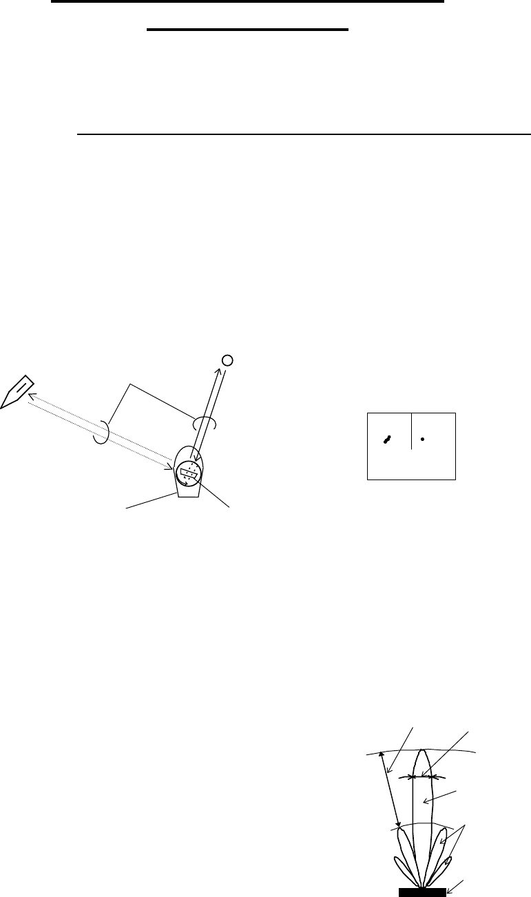
Fig.2-1 What is a radar?
Antenna
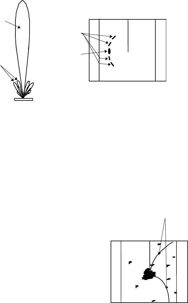
There are many types of antennas generally used for a radar. For example, these include a
parabolic antenna and a slotted-array antenna. The performance of the antenna determines that of
the radar. The dominant factors are the antenna's beam width and side lobe level. The narrower the
beam width, the higher the resolution of the angle direction. The lower the side lobe level, the fewer
the effect of a false echo.
Side lobe
A beam in one direction in which the strongest radio
wave is radiated from the antenna is called the main lobe
and beams in other directions are called "side lobes". The
side lobe level refers to the difference in level between
the largest side lobe and the main lobe.
Beam width
A beam width is defined as the width of the main
lobe at an angle where the radiated power is halved as
measured from the position from which the strongest
radio wave is radiated.
Fig.2-2 Antenna pattern
Buoy
Other ship Radar wave
Your ship
Antenna (Rotating)
Radar display
Beam width
Side lobe
level
Main beam
Side lobe
Antenna
10
2.2 Characteristics of Radar Wave
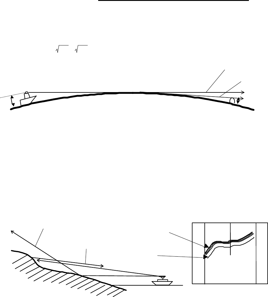
Radio waves from the radar propagate while bending slightly along the terrestrial surface. This
characteristic varies dependent on the density of the atmospheric air. The sight distance D of a radar
generally is said to be approximately 6% longer than the optical sight distance and is calculated using the
equation below :
D (NM) = 2.22 ( h1 + h2 ) where, h1= antenna height in meters
h2= target height in meters
Fig.2-3 Radar wave
Targets difficult to display on screen
The intensity of the reflected wave from a target depends on the distance, height, and size of
the target, as well as its material and shape. Targets constructed with FRP, wood, or other
low-reflectance materials or those that have a small incident angle are difficult to display on a
screen. Therefore, FRP and wooden ships, sandy beaches, and sandy or muddy shallows all are
difficult to catch and require attention when monitoring on the screen. Especially, coast lines on
the radar image appear to be present further from the ship than they are actually located. There-
fore, it is important not to misinterpret the available data.
Fig.2-4 Targets difficult to display on screen
Shadow zones of radar
Radar waves are characteristic in that they propagate straight ahead. Therefore, if the ship's
smokestack or mast is located near the antenna or there is a tall ship or mountain at the side of the
ship, such an object generates a shadow behind it. In this case, some objects produce a complete
shadow and some produce a partial shadow. In an extreme case, the shadow of an object may ex-
tend to a position far away and cannot be displayed on the screen at all. Since these shadows can be
discovered when installing an antenna, the problem can be avoided by changing the place of an-
tenna installation to minimize the shadow. Targets in shadow zones are difficult to display on the
screen.
False echoes
A false echo of an actually nonexistent object may sometimes appear on the screen when
sailing. The following explains the cause of each such phenomena.
h1
h2
Line of sight
Radar Radio
Wave
Earth
Apparent coastline
Actual(invisible)
coastline
Invisible
Visible
3
1
HU
11
A. Ghost echoes
It sometimes happens that one large object near the ship appears at two different bearings.
One is the actual echo and other is a ghost echo generated as the wave is re-reflected from the
ship's own smokestack or mast. The former appears at the correct distance and bearing on the
screen and the latter appears behind the smokestack or mast. This type of false echo is also gen-
erated by re-reflection of waves from bridges and quay walls other than the ship itself.
Fig.2-5 False echoes of radar (Ghost echoes)
B. Multiple echoes
If there is a large vertical reflecting plane near the ship as in the case when your ship passes
alongside a large ship, the wave is repeatedly reflected back and forth between your ship and the
other object. For this reason, two to four images appear on the screen at equal intervals in the same
bearing. A false echo that is generated by such multiple reflections is called multiple echoes. In this
case, an image appearing at the nearest position is the real echo. Multiple echoes disappear as the
ship moves away from the reflecting object or its bearing changes. Therefore, it is not difficult to
determine the correct image.
Fig.2-6 False echoes of radar (Multiple echoes)
C. False echoes caused by side lobe
The radiant beam emitted from an antenna contains side lobes in directions other than that of
the main beam. Since the side lobe level is low, it in no way affects distant targets. However, if
there is a strong reflecting target near the ship, it sometimes appears as a circular-arc false echo on
the screen.
When located near large targets such as land, the
ship's mast, etc. sometimes appears as a false echo
of circular-arc shape.
CAUTION
!
Target
Direct reflection
path
Secondary
reflection path
Mast etc.
Real echo
Ghost echo
Direction of ghost echo
3
1
HU
3
1
HU Real echo
Multiple
echoes
12
Fig.2-7 False echoes of radar (Caused by side lobe)
D. Distant false echoes caused by duct phenomenon
Depending on meteorological conditions, duct phenomenon sometimes occurs in temperature
inverting layers of air. In such a case, the wave propagates erratically reaching a location sur-
prisingly far away from the ship. In this case, a target present at a distant location more than the
radar's maximum distance range appears on the screen presenting a false echo that can be mis-
understood to be present nearer than the actual position. This phenomenon is attributed to the fact
that since echo from the distant target arrives late, it gets out of the pulse repetition frequency and
is displayed on the screen as an echo in the next frequency. If the target distance changes as you
switch over the distance range, you can determine that it is a false echo.
Radar interference
If a radar operating in the same frequency exists near your ship,
interference noise may appear on the screen that is caused by
transmitted waves from that radar. This interference appears in
various ways. In most cases, however, it appears as spiral or radial
patterns.
The RA53/54 radar has a function to eliminate interference. Use
of this function helps you minimize interference.
Fig.2-8 Radar interference
3
1
HU
Antenna
Main beam
Side lobes
Real echo
False sidelobe
echoes
3
1
HU
Radar inrterference
13
2.3 Terms Specific to Radar
HM (Heading Marker)
This is a line-shaped marker used to indicate
the advancing direction of your ship.
North Mark
This marker indicates the north direction. It is
a short line approximately 1/6 of the screen size.
Fig.2-9 Heading Marker and
North Mark
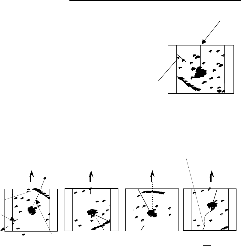
Display modes
This refers to a radar's display modes. There are four display modes depending on the direction in
which the top of the screen faces with respect to the ship.
Fig.2-10 Display modes
Head Up (HU)
In this mode, the ship's heading always indicates the upward direction of the screen. This
mode lets you know the relative positions of your ship and other ships or land.
North Up (NU)
In this mode, the north direction always indicates the upward direction of the screen, allowing
you to compare your ship’s position with a marine chart as you navigate.
Course Up (CU)
The ship's heading in a course-up mode always indicates the upward direction of the screen as
the bearing toward the destination. In this mode, the ship can be maneuvered to sail the shortest
distance to the destination by steering it in such a way that its heading marker always directs to
the upward direction of the screen. If the ship drifts due to tidal current, care must be taken be-
cause the fixed targets move to other positions.
True Motion (TM)
In this mode, the ship is displayed as if it is moving on a marine chart while the fixed targets
such as islands and seashores are fixed in position. When the ship reaches a certain position on the
screen (approx. 2/3 of screen size), the ship is placed back to the opposite side on the screen. (The
top of the screen faces north.)
0.75
0.25
HU
HM(Heading Marker)
North Mark
Ship's
Heading
North
Scheduled
course
HM
EBL
North
mark
HU
NU
CU
TM
Ship's locus
(not displayed on screen)
North North Scheduled
course
0.75 0.75 0.75
0.25
TM
0.25
CU
0.25
NU
0.25
HU
0.75
14
Note: Navigation equipment such as a gyrocompass or magnet compass must be connected to your
radar system before it can be operated in NU, CU, and TM modes. (Refer to Section 3.9 for details
on how to connect your radar to navigation equipment.)
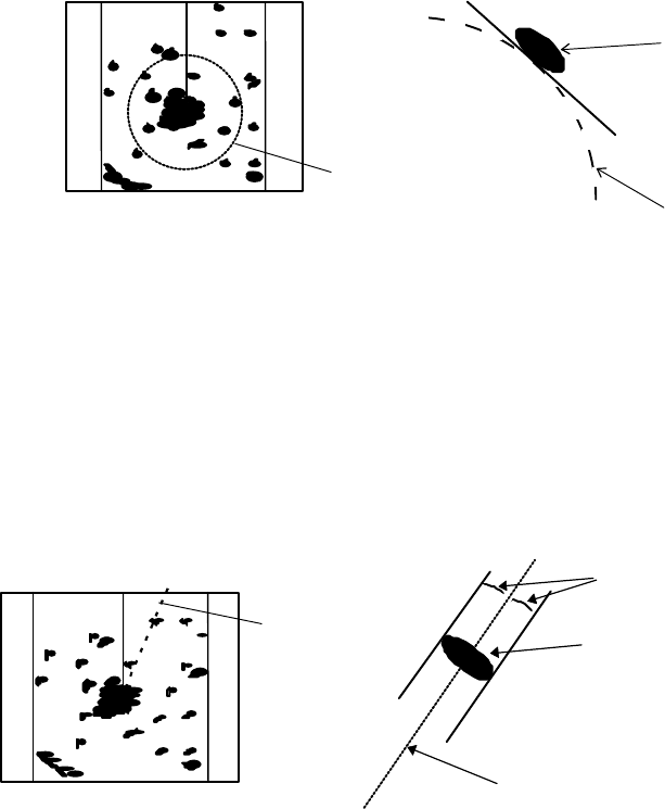
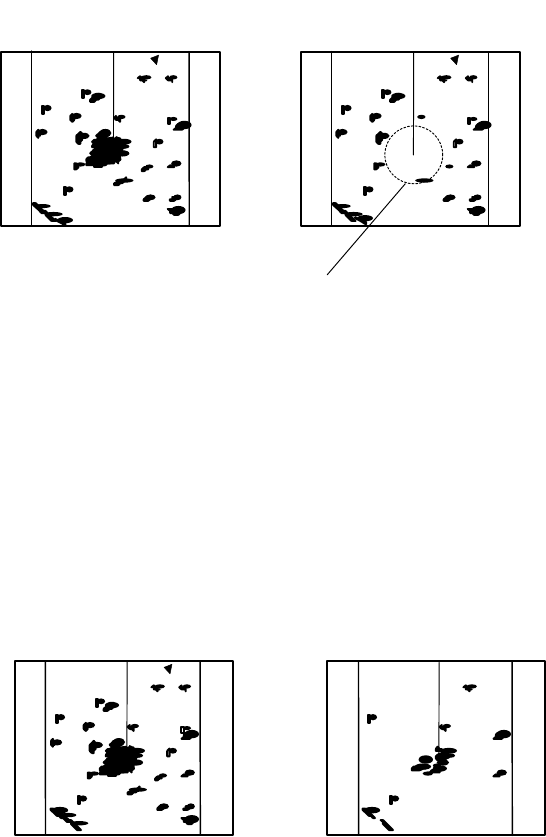
VRM (Variable Range Marker)
This is a circular-shaped marker whose size can be changed as desired. You can use this marker
when you want to examine the distance of an echo from your ship.
When measuring the distance of an echo from your ship, be sure to measure at a point close to the
center of the echo image on the screen.
Fig.2-11 VRM
EBL (Electronic Bearing Line)
This is a marker shaped like a straight line segment that can be changed to any direction centering
around the ship’s position. Use this marker to examine the advancing direction of your ship and its
relative angle with an echo. When measuring the angle of an echo, position the marker at the center of
the echo.
Fig.2-12 EBL
VRM
Echo
0.75
0.25
HU
EBL
VRM
0.75
0.25
HU EBL
Echo
EBL
VRM
15
STC (Sensitivity Time Control)
Since echo signals received by the radar are strong when they are coming from a short distance, it is
difficult to compare signal strength between each reflected signal. To overcome this difficulty, signal
strength is adjusted in such a way that the received signal levels coming from a short distance are low-
ered and those from a long distance are raised. This function should prove useful when there are large
reflected waves from sea surfaces during rough weather.
Fig.2-13 STC
FTC (Fast Time Constant)
When it rains or snows, fine noise may appear over the entire screen, making it difficult to identify
echoes. In such a case, echo images on the screen can be made easily distinguishable by adjusting FTC.
Fig.2-14 FTC
0.75
0.25
HU
STC OFF
STC ON
0.75
0.25
HU
Echo is suppressed
around center
0.75
0.25
HU
FTC OFF
FTC ON
0.75
0.25
HU
Small noises
are reduced.
16
CHAPTER 3. INSTALLATION
This chapter describes procedures for installing the RA53/54 radar in your ship and precautions to
be observed during installation. Follow the procedure below to install the radar.
3.1 Checking Contents of Your Package
First, unpack your package and see if all of the following items are included.
RA53 RA54
Item Q'TY Q'TY
Display unit 1 (RF720A) 1 (RF720A)
Scanner unit 1 (RB717A) 1 (RB718A)
Display cover 1 1
Fuse 2 2
Interconnecting cable 1 (10 m) 1 (10 m)
Power supply cable 1 (2 m) 1 (2 m)
M12 hexagonal bolt 4 sets 4 sets
Carbon brush 2 2
The package contains a 10m interconnecting cable as an accessory. Longer cable is also available as
an option as listed in Tab.3-1.
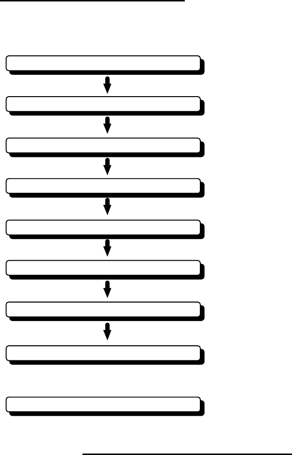
Checking contents of your package
Checking power supply voltage
Determining place of installation
Installing scanner unit
Installing display unit
Connecting cables
Adjustment
Connecting external equipment
When discarding Your radar
17
Tab.3-1 Optional Interconnecting Cable
In addition to the above components included with your package, the following items are also re-
quired. Please prepare them separately.
Item QTY Remarks
Tapping screw or M5 bolt and nut 6 sets To install display unit
Grounding wire 1 Earth line for display unit
Grounding wire and crimp terminal 1 set Earth line for scanner unit
3.2 Checking Power Supply Voltage
3.2.1 Power Supply Requirements
For the RA53/54 radar to be operated normally, the power supply (battery) detailed in Tab.3-2 is
required. Note also that if the battery is discharged, its voltage may fluctuate greatly, causing the radar
to malfunction. When to starting up the radar system or starting transmitting, an additional rush cur-
rent is required on the power supply line. Carefully check the power supply system including wiring by
using a circuit tester.
Tab.3-2 Power Supply Requirements
*A.C. power cannot be used
3.2.2 Fuse Replacement
For the RA53/54 radar to be operated safely, proper rated fuses must always be used. Tab.3.3 is
fuse rating table. All these fuses are provided as spares.
Tab.3-3 Supply Voltage vs Fuse Ratings
RA53/RA54
Cable length Product No.
15m 242J159098B
20m 242J159098C
30m 242J159098D
Supply voltage used
Maximum current
Allowable range of voltage
DC12V 14A 10.2-41.6V
DC24V 6A 10.2-41.6V
Main Fuse Motor Fuse
15A/250V or 125V *
(6.3 dia. x 32mm) T3.15A/250V or 125V
(5 dia. x 20mm)

18
3.3 Determining Place of Installation
3.3.1 Scanner unit
A radar's target detection capacity varies greatly depending on the position of the scanner. An ideal
position is a location high above the ship's keel line where there is no obstacle all around the scanner. In
an actual ship, such an ideal location is limited by various factors. To comply with FCC RF exposure
requirements, the radar antenna for this scanner must be installed to provide a separation distance of
80 cm or more from all persons. Therefore, consider the following suggestions when you determine the
place to install the scanner:
(a) Install scanner at a position as high as possible.
The higher the installation position, the longer the radio ranging distance. Install the
scanner at a position as high as possible after considering the ship's hull structure and radar
maintainability.
(b) Install scanner away from smoke-stack and mast
If the scanner is installed at the same height as the smoke-stack or mast, radar waves may
be blocked, creating shadow zones or generating false echoes. Therefore, do not install the
scanner at such a position.
(c) Install scanner forward away from obstacle.
To avoid creating shadow zones or generating false echoes, install the scanner at a position
nearer to the ship's bow away from obstacles. When installing the scanner on a mast, posi-
tion it in front of the mast. (If obstacles cannot be avoided for the ship's structural reasons,
refer to "Shifting away from obstacles" described Page 13.)
(d) Do not install the scanner near hot or heat-generating items.
Do not install the scanner at a position where it may be subjected to smoke or hot air from
smokestacks or heat from lamps.
(e) Install the scanner away from antennas of other equipment.
Install the scanner as much away from the antennas of a direction finder, radio transceiver,
etc. as possible.
To eliminate the interference, install the scanner
away from the antenna of radio transceivers.
(f) Make the cable length as short as possible.
Keep the distance from the scanner to the display unit within the standard cable length
of 10 m. If you use longer cable for unavoidable reasons, limit the cable length to a maximum
of 100 m for RA53/54.
3.3.2 Display unit
The display unit can be installed on desktop, wall surface, or ceiling. Determine the place to install
the display unit that is convenient for navigation and radar operation after considering the following
suggestions:
(a) A place where you can see the ship's bow when you raise your face from the radar screen.
(b) A place where there is no direct sun-light to avoid display temperature up.
(c) A place where there is good ventilation and minimum vibration.
(d) A place where the display unit is further away than the minimum safe distance from a
magnet compass as listed in Tab.3-4 below.
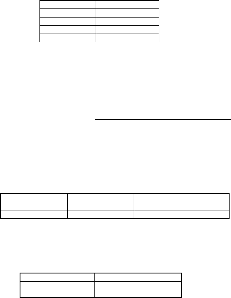
Tab.3-4 Minimum Safe Distance from Magnetic Compass
Master compass
Steering compass
Scanner unit
2.0m 1.4m
Display unit
2.0m 1.4m
!
CAUTION
19
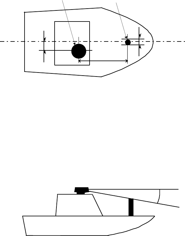
3.3.3 Shifting away from obstacles
1. Shifting from keel line
By shifting the scanner position from the keel line to the starboard side of the ship, it is
possible to move shadow zones to the port side which makes it possible to keep vision clear in
the bow direction. The distance to be shifted can be obtained by calculation depending on the
distance from the scanner to obstacles using the following equation:
Ls=0.4R+D/2 [m] (when R<15m)
Ls=0.025R+D/2 [m] (when R>=15m)
where Ls = distance to be shifted from keel line
D = diameter of obstacle on keel line
R = distance from scanner to obstacle
Fig.3-1 Shifting from keel line
2. Obtaining sufficient dip angle
Raise the scanner position so that there is a sufficient dip angle θ available between the
line of sight from the scanner to the obstacle and the horizontal line. By raising the dip angle
above 5°, it is possible to prevent mid- and long-distance shadow zones. The radar cannot
detect objects below the line of sight.
Fig.3-2 Obtaining sufficient dip angle
Ls
R
D
Scanner Unit Obstacle
Keel line
Horizontal line
Line of sight
θ
20
3.4 Installing Scanner Unit
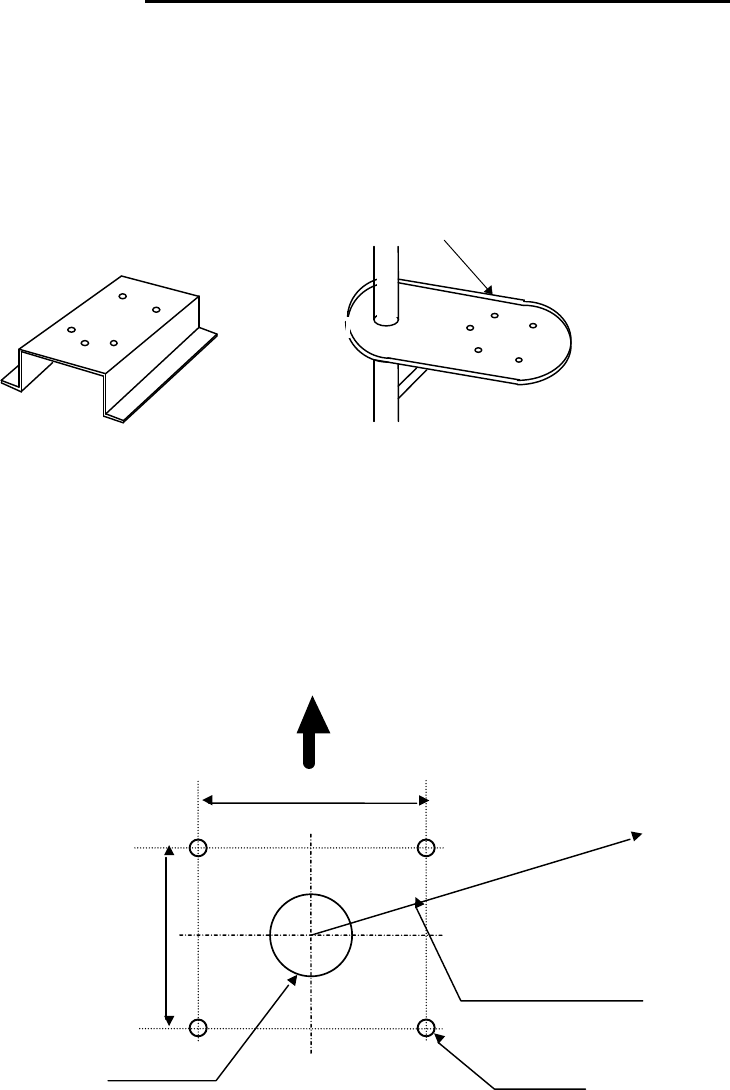
When you have decided the place of installation, install the scanner unit. If a mount base like the
one shown below is available, it may be easier to install the scanner. If such a mount base is not available
in your ship, you may install the scanner directly to the roof, etc. In such a case, pay attention to the
water drain tube located at the bottom of the scanner unit during installation.
Note : When the radar mast or mounting bracket has a curvature of more than 2mm, repair it or use
spacers.
Fig.3-3 Mount base
Referring to Fig.3-4, open holes in diameter of 12 mm (0.47 in.) at five locations in the mount base
and use these holes to fix the scanner unit to the mount base with hexagonal bolts. (Use the template
included with this manual.) The bolts included with your radar equipment will suffice for mount base
thickness of 9 to 14 mm (0.35 to 0.55 in.). If the mount base is thicker or thinner than this, prepare bolts
listed in Tab.3-6.
Fig.3-4 Hole positions for mounting scanner
Do not use an edge that might trap water.
Unit:mm
199
(7.83 in.)
Forward
185
(7.28 in.)
Rotation Radius
R550 (3 ft antenna)
R700 (4 ft antenna)
R1000 (6 ft antenna)
14 dia.
×
4
(0.55 in.)
Cable inlet
100 dia.(3.97 in.)
RA53/54 Scanner
21
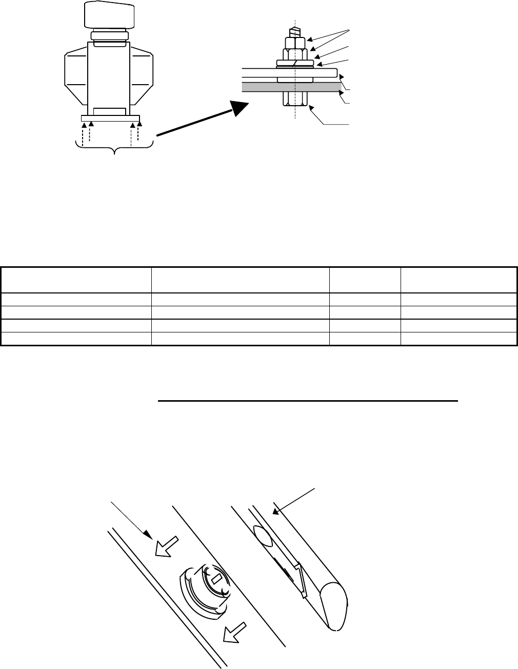
Fig.3-5 Fixing Scanner Unit
Tab.3-5 Bolts for Mounting Scanner Unit
3.5 Installing Antenna Unit
Remove the protective cap covering the rotary coupler on the top of the scanner. Match the antenna
radiation direction to direction of the arrow markings on the rotation base and fix the antenna in position
using the four M8 accessory bolts.
Thickness of
mount base Bolts necessary to
fix scanner Material Remarks
1-4mm(0.04-0.16 in.) M12 x 45 (1.5mm pitch) Stainless
4-9mm(0.16-0.35 in.) M12 x 50 (1.5mm pitch) Stainless
9-14mm(0.35-0.55 in.) M12 x 55 (1.5mm pitch) Stainless Included with radar
14-19mm(0.55-0.75 in.) M12 x 60 (1.5mm pitch) Stainless
Arrow
Fix four screws
Double nuts
Spring washer
Washer
M12 Hexagonal bolt
Mount base
Scanner base
Antenna radiation surface
22
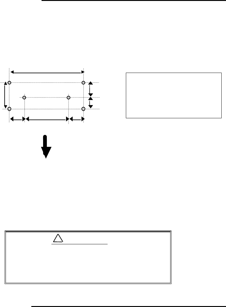
3.6 Installing Display Unit
After you have finished installing the scanner unit, install the display unit in the same way. Choose
the proper bolt length according to the thickness of the surface on which you are going to install the
display unit. Hole diameter is different using bolts from using tapping screw. When using tapping screw,
open holes in adequate holes. When using bolts and nuts, open holes in diameter of 6 mm (0.24 in.). When
you have opened holes, install the pedestal part first and then the display unit.
Fig.3-6 Hole positions for display unit
Note : When you install the display by flush mount, refer to appendix "OUTLINE DRAWING".
Slide off four triangle corner covers, and fix the display unit to the panel with screws. After fixing the
display unit, put on corner covers to the corner of the display unit. See APPENDIX.
3.7 Connecting Cables
Lay cables firmly in place by following the instructions below.
Note1: Do not bind the cable for the radar collectively with cables of other equipment (espe-
cially power supply cable).
Note2: Leave clearance near the inlet of the display so you can remove the display unit eas-
ily. This facilitates installation and maintenance of the display unit. (Refer to Ap-
pendix.)
Note3: Because the cable has a connector fitted on the display and scanner side, if it is nec-
essary to pass cable through a narrow path, fix the scanner-side connector vertically
using vinyl tape before passing cable through the path.
Note4: Lay cable along the ship's hull or wall surface and attach it in place at intervals of
about 40 cm.
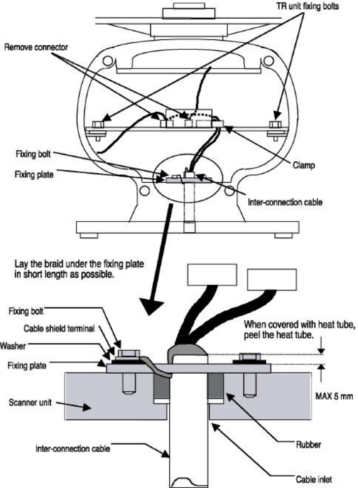
3.7.1 Interconnecting cable (See Fig.3-9)
• Ensure that the radar is off. Connect the cable to the socket labeled "SCANNER" on the rear panel
of the display unit.
‚ Use a T-wrench to remove the back covers of scanner unit.
Avoid operating display in direct sunlight.
The temperature inside becomes high and
display may be broken.
!
WARNING
360
84
Fitting hole
(14.17 in.)
(3.31 in.)
Hole diameter
6mm : Bolts and Nuts
Adequate : Tapping screws
Recommended screw
M5 or equivalent
Unit : mm
47 (1.85 in.)
37 (1.46 in.)
60
(2.36 in.)
240
(9.45 in.)
60
(2.36 in.)
Forward
23
ƒ Remove the two bolts securing the transceiver; pull out the transceiver after removing two con-
nectors.(to Motor(J5), to Heading switch (J3) )
„ Remove the four bolts securing the fixing plate at the cable entrance.
… Remove the metal fixing plate, rubber seal and washer that secure the cable. Pass the cable
through as shown in the diagram below; replace the above items and tighten the bolts.
† Return the transceiver to its original position and secure it with the removed bolts.
‡ Connect 7-pin connector to J2 and 9-pin connector to J1 of PCB. And connect two connectors that
were removed at ƒ.
ˆ Refit the scanner covers.
Take care not to pinch the cable when refitting the cover.
Fig.3-9 Interconnecting cable
24
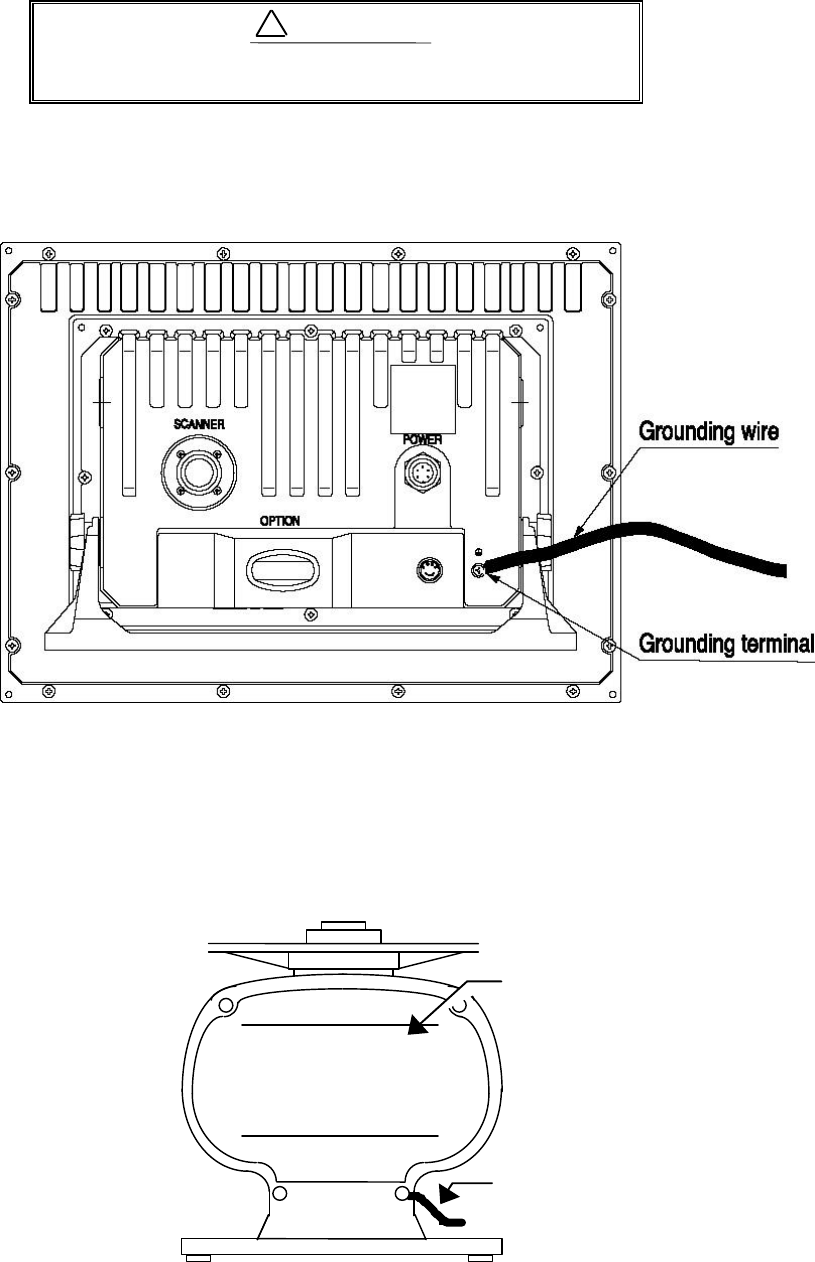
3.7.2 Grounding wire
Connect grounding wire before connecting power
supply cable. Leakage current is too high.
Connect grounding wire from the grounding terminal on the rear panel of the display unit to the
ship's hull as shown below.
Fig.3-10 Grounding display unit to earth
Connect grounding wire from one of the bolts you have attached when installing the scanner unit to
the ship's hull as shown in Fig.3-11. (The crimp terminal and grounding wire are not included with the
radar equipment.)
Fig.3-11 Grounding scanner unit to earth
!
WARNING
Grounding wire
→
To ship’s hull
Scanner cover
25
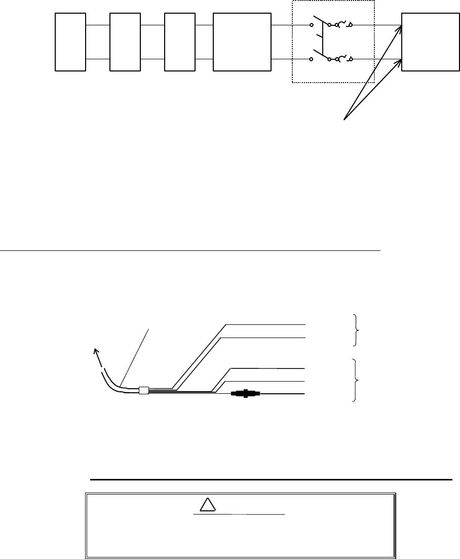
3.7.3 Power supply cable
Power is fed through a knife switch ( or circuit breaker) and protective fuses, as shown in below.
WARNING: Do not apply over 41.6V to Radar
or Radar may be broken.
Fit the power supply cable (included with your radar) to the receptacle labeled "POWER" on the rear
panel of the display unit. And connect to power supply as follows. (When you do not connect external
equipment, put tape on red and green wire.)
Place the Fuse and connection part where there is no water splashes and the area is dry.
If you extend the power supply cable, use a suitable cable as below.
Ship's Power Voltage Cable conductor Cable max. length
cross section
12Vdc 3.5 mm2 3 m
6.0 mm2 5 m
24Vdc 2.0 mm2 6 m
3.5 mm2 10 m
Fig.3-12 Power supply cable
3.8 Adjustment
Be sure to operate the following adjustment. If this
is not adjusted properly, the radar picture does not
display true image.
When you have finished installing the scanner and display units and connecting cables, turn on the
power to the display and scanner units and check to see if they operate normally without problem. Then
make adjustments as detailed below and check to see if the units operate normally again.
1. TUNING Refer to Adjusting tuning circuit in 5.5.4.5.5
2. HEADING DIRECTION Refer to Adjusting angle in 5.5.4.5.5
3. DISTANCE Refer to Adjusting distance in 5.5.4.5.5
!
CAUTION
Generator
Switchboard
Charger
Storage
Battery
12/24V
Main switch panel
(Knife Switch with Fuses)
Radar Display
Unit
DC voltage
reference points
White
Black
Gray
Green
Red
Power supply cable
To display unit
DC+
DC-
Ground
NMEA-
NMEA+
To external
equipment
To power supply
26
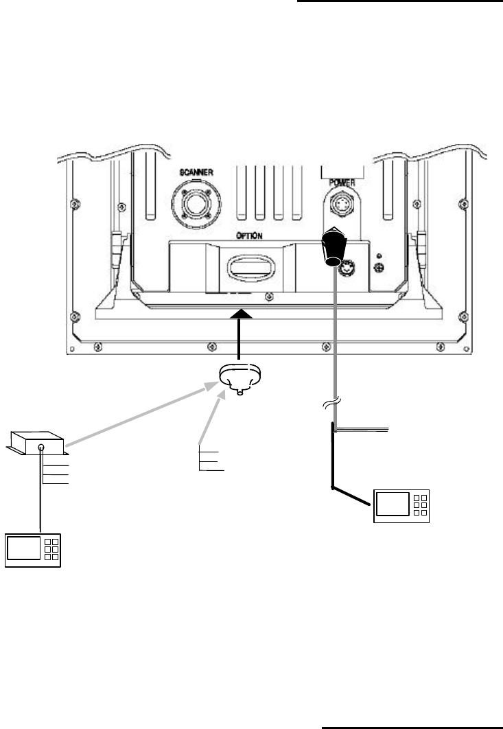
3.9 Connecting External Equipment to Display Unit
The display unit has two channels of NMEA input. One is standard in power cable. The other is
necessary to connect optional parts (Junction box with OPTION cable).
OPTION connector is located at display’s rear panel for connecting external equipment such as a
GPS, LORAN, or gyro compass. You must have a Junction box with OPTION cable. (Refer to CHAPTER
8 (4) External interface.)
Note: SIN/COS and MOB signals cannot be used on Junction Box.
* Junction box with OPTION cable (Order No. RZ704A)
Fig.3-13 Connecting external equipment to display unit
3.10 Countermeasure for Electromagnetic Interference
RA53/54 radar provides shields in the units and the inter-unit connection cable. When the radar,
however, is closely installed to radio equipment such as VHF transceiver, UHF transceiver, etc., or the
radar and/or radio equipment are not sufficiently grounded to the hull or ship's earth, the radar may
happen to cause EMI trouble.
Followings are general procedures for reducing EMI due to radars. When installing radars, refer to
them, and also check the radio equipment EMI trouble with operating the radar and radio equipment.
OPTION cable
Junction box*
note
(RZ704A)
POWER cable
External NMEA equipment
(GPS,LORAN,etc.)
External NMEA equipment
(GPS,LORAN,etc.)
Green :NMEA-
Red :NMEA+
To power supply
Other radar,
slave monitor,
External buzzer,
Gyro I/F
Other radar,
slave monitor,
External buzzer,
Gyro I/F,
SIN/COS.
MOB(NMEA out)
27
(1) Installation Place of Radar
The display unit, scanner unit and inter-unit connection cable should be located apart from the
main unit, feeder, antenna coupler and antenna of radio equipment as far as possible.
Especially, proper installation of the feeder, antenna coupler and antenna of radio equipment is
very important to improve EMI trouble.
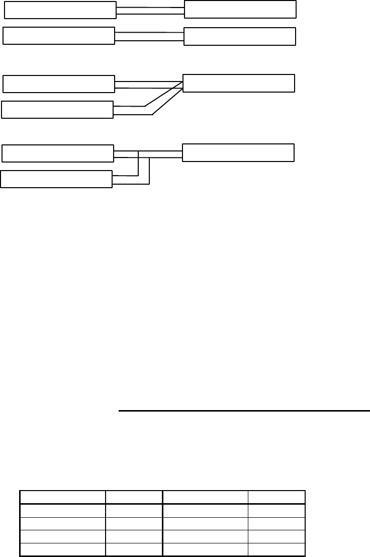
(2) Laying Power Supply Cables
Following connections A and B are recommended to reduce conduction noise generated from ra-
dar. Connection C should not be used.
Connection A
(Very Good)
Connection B
(Good)
Connection C
(Bad)
(3) Grounding
All equipment should be firmly grounded at the earth nearest hull with copper plates or braided
wires.
Improvement Procedure for EMI
(1) Confirm grounding on the radar and radio equipment. However, some equipment, on which
grounding is not always necessary, have a possibility of EMI improving when taking off their
grounding. Try to take off grounding.
(2) Confirm power supply cable connections and modify to the connection A or B above.
(3) Try to shift the display unit and inter-unit connection cable of radar to be apart from radio
equipment.
(4) Try to shift the feeder of radio equipment to be apart from each units and the inter-unit connec-
tion cable of radar.
(5) Try to shift the antenna coupler and antenna of radio equipment to be apart from the scanner
unit and inter-unit connection cable of radar.
3.11 When Discarding Your Radar
When discarding your RA53/54 radar, consult the distributor to get information on precautions to be
followed. Tab.3-6 below lists the primary component materials of the RA53/54 radar for your reference.
Tab.3-6 Component Materials
Scanner unit Material
Display unit Material
Radome AES Front panel ABS
Chassis A5052P Rear panel ADC12
Base ADC12 Pedestal ABS+PC
Antenna A5052P
RADAR
RADIO EQUIPMENT
SHIP'S SUPPLY
SHIP'S SUPPLY
RADAR
RADIO EQUIPMENT
SHIP'S SUPPLY
RADAR
RADIO EQUIPMENT
SHIP'S SUPPLY