Koden Electronics RB718A Marine Radar RA54 User Manual OME RA5354 2of4
Koden Electronics Co., Ltd Marine Radar RA54 OME RA5354 2of4
Contents
- 1. Manual1of4
- 2. Manual2of4
- 3. Manual3of4
- 4. Manual4of4
Manual2of4
28
CHAPTER 4. FUNCTIONS AND NAMES
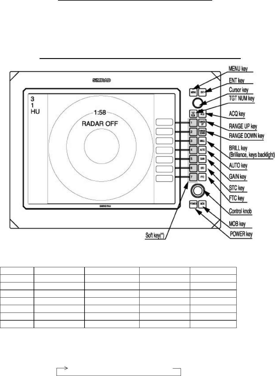
Function and name of each part
The RA53/54 radar consists of a display unit to display video images on a screen and a scanner unit configured with
an antenna to radiate radio waves and other components. The display unit has on its front panel eighteen(18) push-switch
keys and one cursor key that lets you move a cursor in any desired direction. A combination of these keys allows you to
utilize all functions of your radar, providing a comfortable, easy way to operate.
4.1 Key layout
Key No.
SET1 SET2 SET3 SET4
1 EBL1 EBL2 DATA PPI
2 VRM1 VRM2 DEL PPI/3D
3 VAR RNG FL EBL2 ALL DEL PPI/PPI
4 TRACK FL VRM2 TRACK PPI/NAV
5 TARGET GZ ZOOM ALL PPI
6 SEL WIN OFF-C PICTURE ALL PPI2
7 NEXT NEXT NEXT NEXT
Tab. 5 Function of soft key (Factory setting)
*Every time Next key is pressed, soft key group switches as follows.
SET1
→
SET2
→
SET3
→
SET4
29
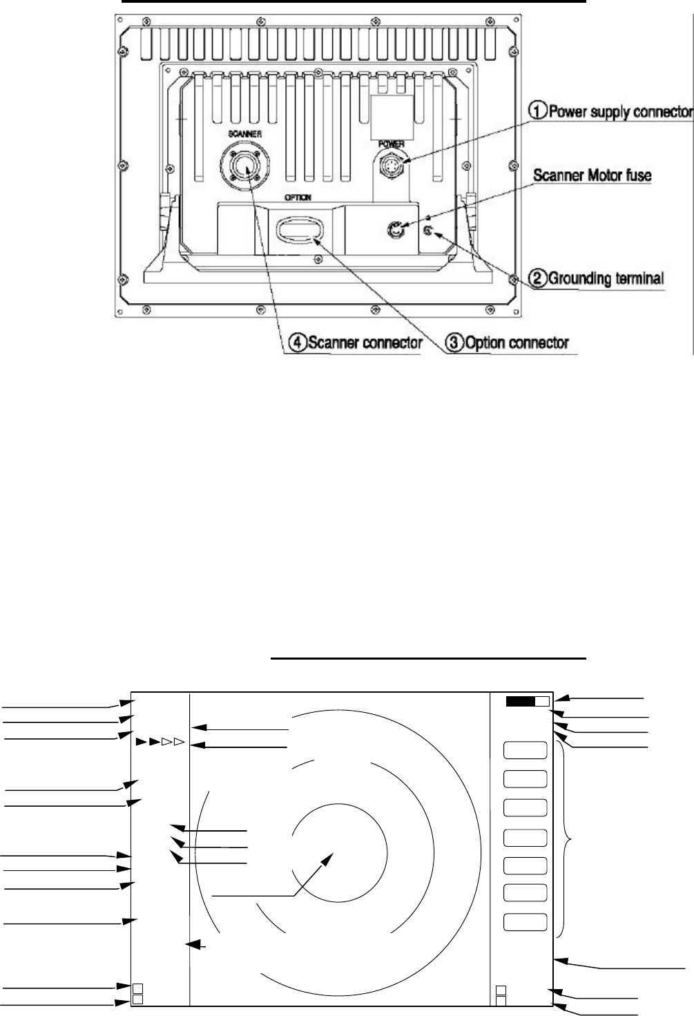
4.2 Rear panel
1. Power supply connector
Use this connector to plug in the power supply cable. Standard NMEA interface terminal is included in this
connector. Refer to Section 3.7 “ Connecting Cables “ and Section 3.9 “Connecting External Equipment to Display
Unit “.
2. Grounding terminal
Use this terminal to connect grounding wire. Refer to Section 3.7 (3) “Grounding wire”.
3. Option connector
Use this connector to connect NMEA, an external monitor, external buzzer and GYRO I/F. A dedicated cable or
dedicated module box is required to connect these pieces of equipment. Refer to Section 3.9 “Connecting Ex-
ternal Equipment to Display Unit”.
4. Scanner connector
Use this connector to plug in the inter-connecting cable to connect the scanner unit.
Refer to 3.7 “Connecting cable “.
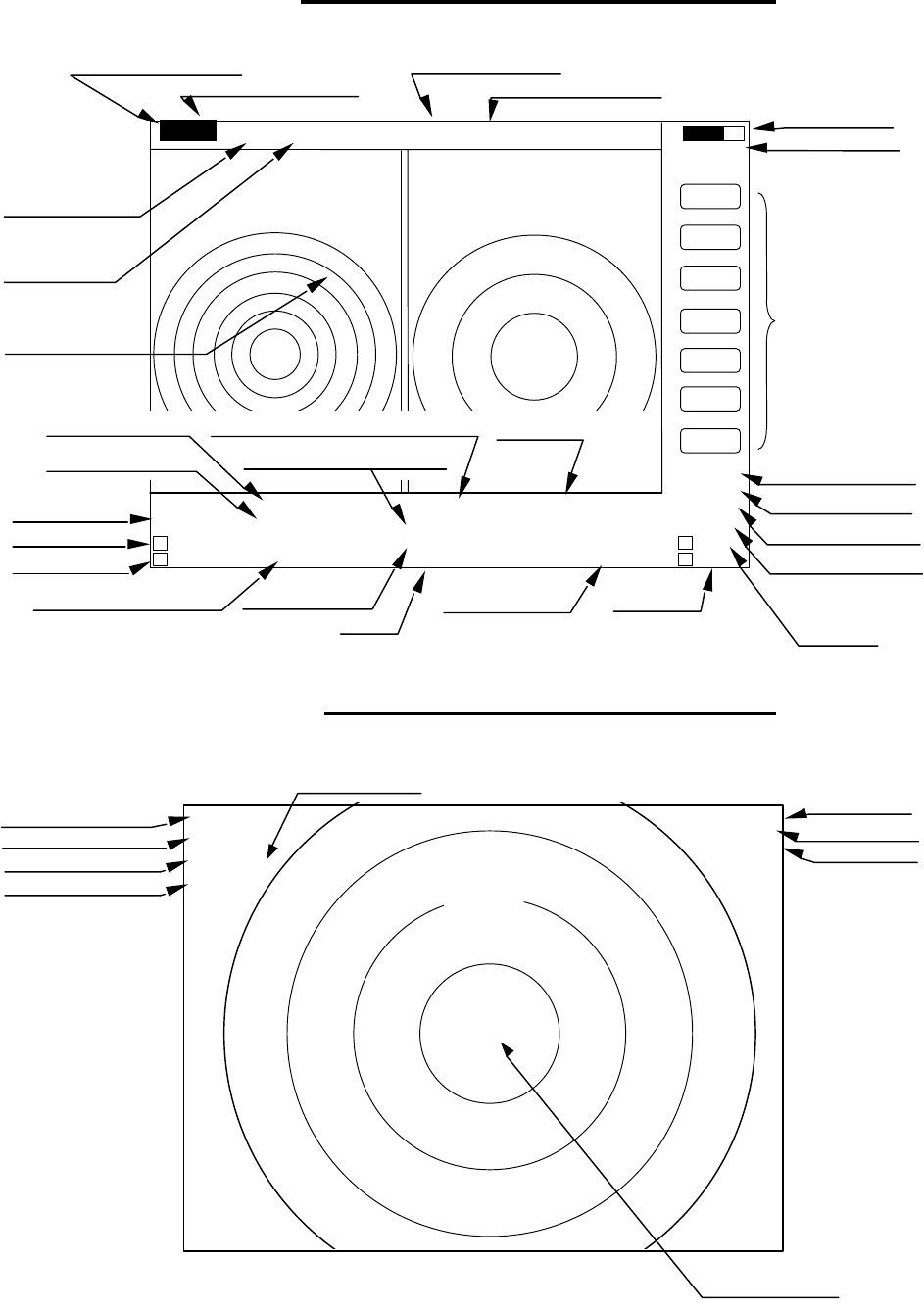
4.3 Radar screen( Single screen )
Ship’s position
EBL2
VRM2
Indicate soft key
3
1
HU L
1:58
+
RADAR OFF
EBL1
VRM1
EBL2
VRM2
FL EBL2
FL VRM2
NEXT
A
HOLD
ZOOM
OFF-C
LAT/LON
35°08. 42N
139°02. 53E
2 129. 8°
2 12. 34NM
0.23NM
HDG
129.0 °T
SPD
12.0 KT
G 59
S AT
F AT
ST1
GZ IN
TK 15 S
WP
134.4 °
12.5NM
+LAT/LON
35°08.42N
139°02.53E
1 129. 8°
1 12. 3NM
Tune meter
Picture hold
Zoom
Off-center
Range
Range ring interval
Display mode
Heading angle
Cruising speed
Enlarging echo
Guard zone
Track
Way point
EBL1
VRM1
Pulse width
Course error
Gain
STC
FTC
Cross cursor
Cross cursor position
(LAT/LON or Distance/Bearing)
30
4.4 Radar screen (Dual screen)
ex) PPI/PPI screen
4.5 Radar screen (All PPI screen)
Tune meter
Picture hold
Indicate soft key
SPD 12.8KT GZ R IN WAY P 134.4°
HDG 129.2° GZ L IN 12.5NM
+MK 38.4° ST1 LAT 35°08.42N 2 129.8°
5.28 TK 15S LON 139°02.53E 2 3.62NM
6
1.0_ HU L
.75
.25
EBL1
VRM1
EBL2
VRM2
FL EBL2
FL VRM2
NEXT
A
HOLD
0.23
XTE >>>
1 129.8°
1 12.34NM
AT1
G 59 / AT
S AT / AT
F AT / AT
Range(Left screen) Range(Right screen)
Range ring interval Range ring interval
(Left screen) (Right screen)
Display mode
Pulse width
Cross cursor
Course error
EBL1
VRM1
+
Cruising speed Guard zone(Right screen) Way point
Heading angle Guard zone(Left screen)
Cross coursor position Enlarging echo Ship’s position VRM2
(LAT/LON or Distance/Bearing) Track EBL2
AUTO (Left/Right)
Gain (Left/Right)
STC (Left/Right)
FTC (Left/Right)
3
1
HU L
GZ IN 1:58
+
RADAR OFF
OFF-C
HOLD
ZOOM
Off-center
Picture hold
Zoom
Range
Range ring interval
Display mode
Guard Zone
Pulse width
Cross cursor
31
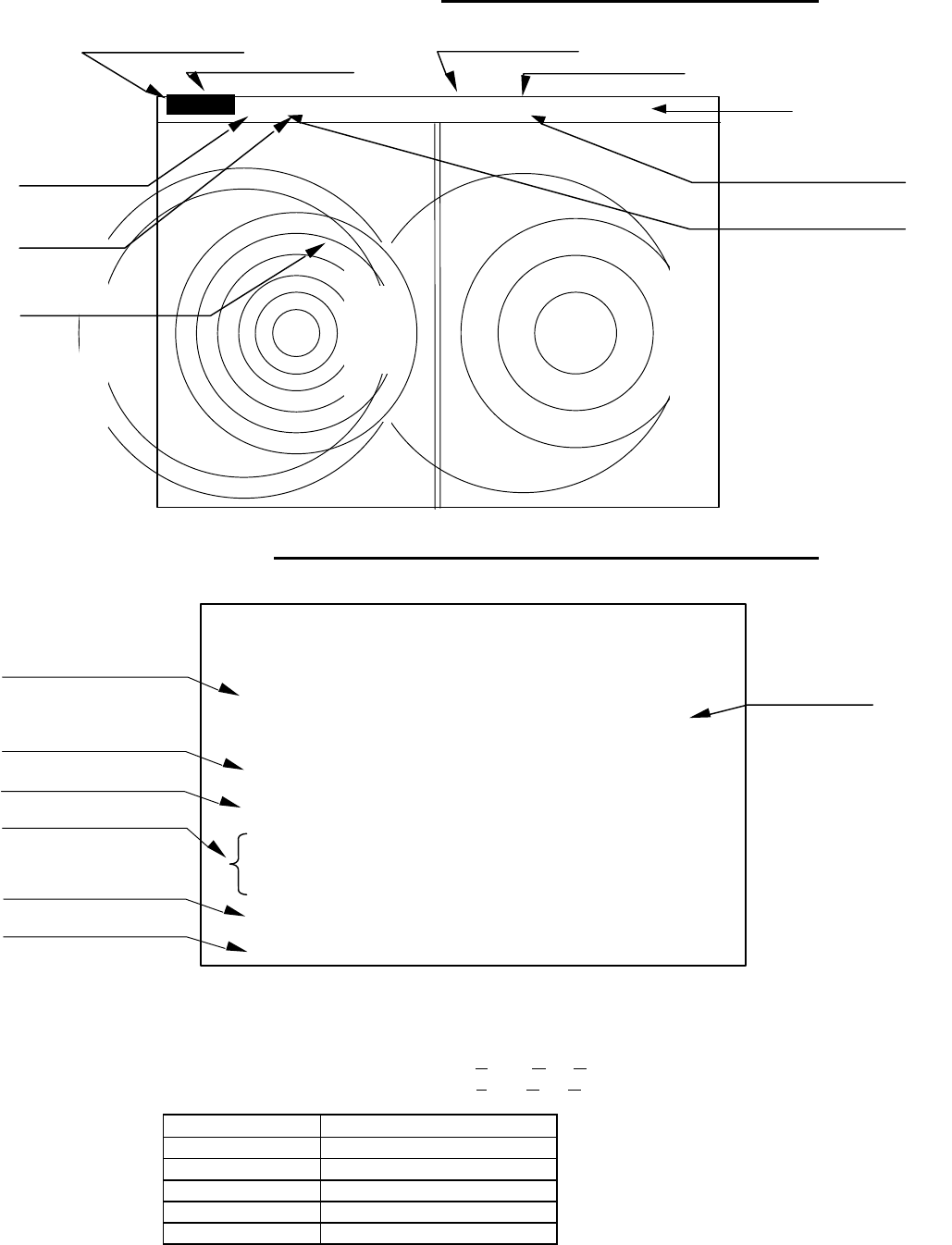
4.6 Radar screen (All PPI /PPI screen)
4.7 Navigation screen
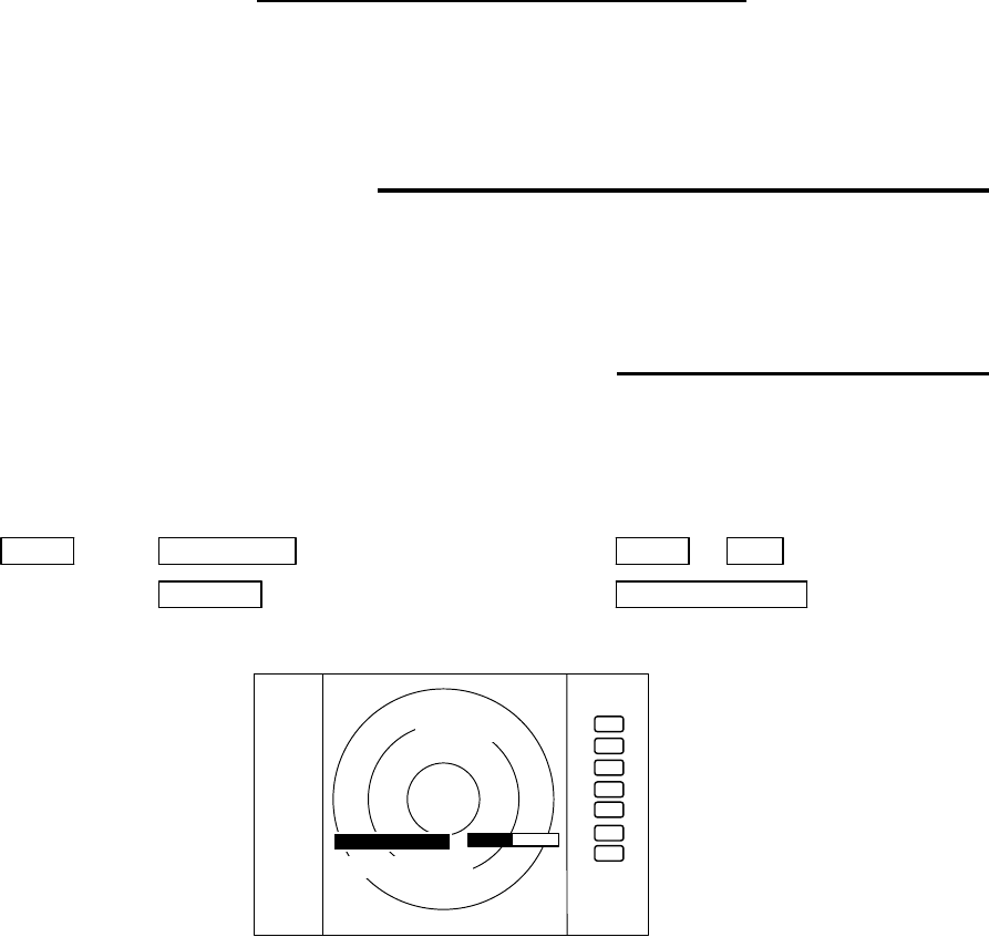
To show the NAV display, you need to connect a GPS receiver to your radar. The NAV display shows the
position and cruising speed of your ship, seawater temperature, and other navigation information.
Note: Heading angle will be displayed "COG" when Course Over Ground data is used.
Note: Cruising speed will be displayed "SOG" when Speed Over Ground data is used.
Deviation from
Indication mark
0.00
--
><
0.02
--
>
or
<
0.04
--
>>
or
<<
0.08
--
>>>
or
<<<
0.16
--
>>>>
or
<<<<
Tab.6 Indication of deviation from course
Picture hold
Guard zone(Right screen)
Guard zone(Left screen)
6
1.0_ HU L GZ IN
.75
.25 GZ IN HOLD
Range(Left screen) Range(Right screen)
Range ring interval Range ring interval
(Left screen) (Right screen)
+
Display mode
Pulse width
Cross cursor
NAV DISPLAY
WP 134.4° COURSE
12.5NM >>>
HDG 129.0° 0.23NM
SPD 12.8KT
LAT 35°08.42N
LON 139°02.53E
TEMP 20.5°C
DEPTH 93.2M ST’BY
Way point
Heading angle
Cruising speed
Current position
Sea water temperature
Depth of water
Course error
(XTE)
> Indicates starboarding the helm
< Indicates porting the helm (left)
32
CHAPTER 5. OPERATION
Basic operation of radar
The RA53/54 radar has several fixed-function keys on the front panel. Press the relevant key to control these func-
tions. Also, you can customize particular functions to the soft-keys. The following paragraphs explain the operation
of each key.
5.1 Turning On and Off the radar
(1) Turning On
Press the "POWER" key. Buzzer sounds a short beep and then the radar system will be powered.
Screen brilliance will be set to the level at which the radar system was turned off.
(2) Turning off
Keep pressing the "POWER" key more than 3 seconds, and then the radar system will be turned off.
5.2 Adjusting brilliance of screen and key-backlight
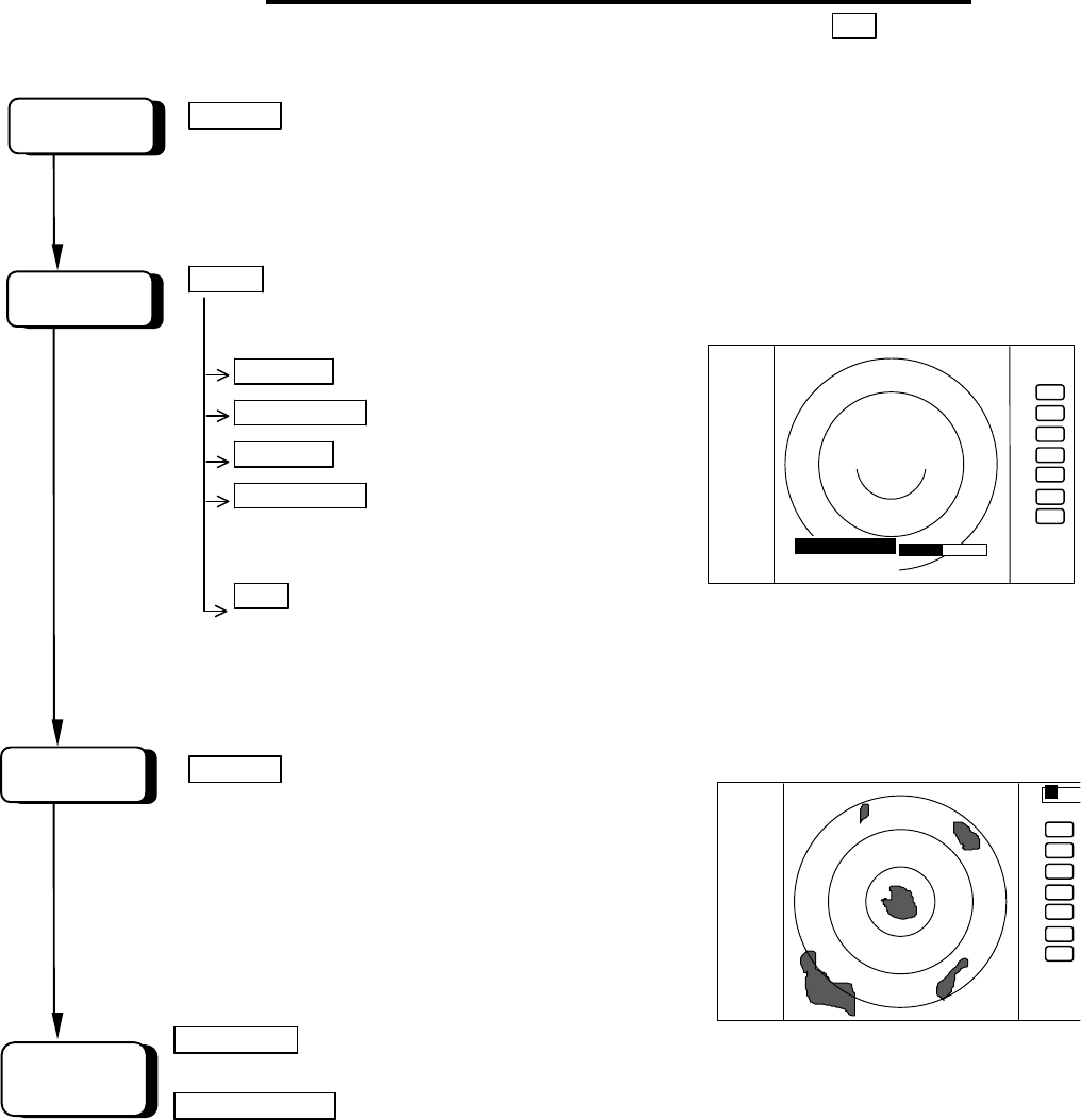
(1) Press the "BRILL" key. A bar graph and figures appear in the lower left corner of the screen, indicating the screen
brilliance. Under the screen brilliance figure, a figure indicating key-backlight brilliance will appear.
(2) Adjust each item with the control knob. Items can be selected by the UP/DOWN cursor.
(3) When the adjustment is finished, press either the "BRILL" key or the "ENT" key to exit from the adjustment
screen. (Pressing some other key after adjustment will lead to the function of the pressed key.)
BRILL → Control knob (Adjustment of brilliance) → BRILL or ENT
→ Up/Down (Selection of brilliance, key-backlight) → Other function key Move to other
functions
.75
.25
HU
BRILLIANCE 50
ST’BY
+
KEY BACKLIGHT 4
33
5.3 Basic Operations
xxx = Keys to press
5.3.1 Turning On and Off
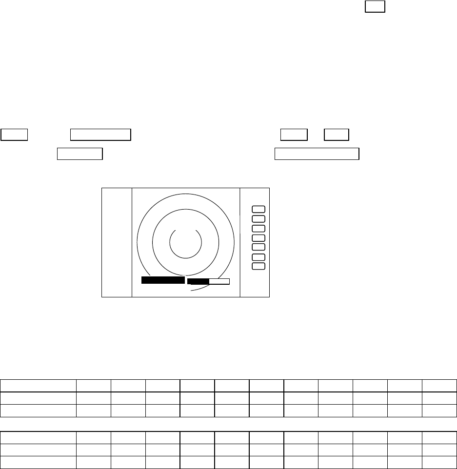
POWER Press POWER key to turn the radar on.
The 2 minute countdown timer starts and the RADAR OFF
sign will be displayed.
Press the "BRIL" key.
BRILL Control bar is indicated on the screen.
Brilliance Up/Down Select brilliance.
Control knob Adjust brilliance with knob.
Key backlight Up/Down Select key backlight.
Control knob Adjust key backlight with
knob.
ENT Press "ENT" key to return.
Radar turns into ST'BY mode after 2 minutes and the ST'BY sign will be displayed.
5.3.2 Transmitting
POWER Press the POWER key to transmit, and
the radar picture appears on the screen.
Further press of the POWER key
brings the radar to STANDBY mode.
To turn off the radar, press and hold the
POWER key more than 3 seconds.
RANGE UP or Pressing the RANGE UP key increases the
range scale.
RANGE DOWN Pressing the RANGE DOWN key decreases the range scale
SCREEN
POWER ON
START
CHANGE
RANGE
.75
.25
HU
BRILLIANCE 50
1:58
RADAR OFF
+
KEY BACK LIGHT 4
AT
.75
.25
HU
+
34
5.3.3 Adjusting the brilliance of screen and key-backlight
xxx = Keys to press
(1) Press the "BRILL" key. (Bar and figure indicating brightness, and figure indicating backlight appears on the
screen.)
(2) Select brilliance or key-backlight with the up-down cursor.
(3) Adjust each item with the control knob.
(4) When the adjustment is finished, press either the "BRILL" key or the "ENT" key to exit from the adjustment screen.
(Pressing some other key after adjustment will lead to the function of the pressed key.)
BRIL → Control knob (Adjustment of brilliance) → BRIL or ENT
→ Up/Down (Adjustment of brightness, panel) →Other function key Shift to other functions
5.3.4 Changing the range scale (RANGE UP, RANGE DOWN)
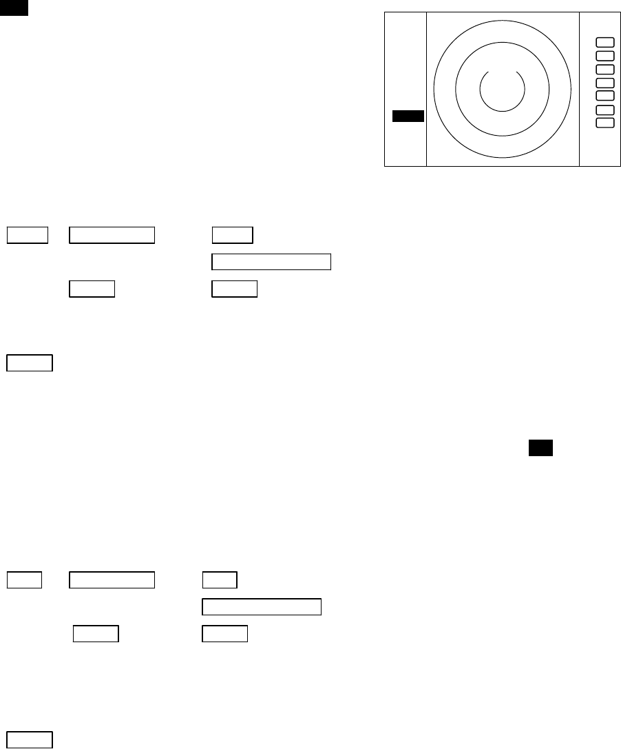
Pressing the RANGE UP key increases the range scale and the RANGE DOWN key decreases the scale.
RA53
RANGE 0.125
0.25 0.5 0.75 1.5 3 6 12 24 48 64
Number of rings 2 2 2 3 6 6 6 6 6 6 4
Range ring interval
0.0625
0.125
0.25 0.25 0.25 0.5 1 2 4 8 16
RA54
RANGE 0.125
0.25 0.5 0.75 1.5 3 6 12 24 48 72
Number of rings 2 2 2 3 6 6 6 6 6 6 6
Range ring interval
0.0625
0.125
0.25 0.25 0.25 0.5 1 2 4 8 12
5.3.5 Automatic adjustment (AUTO)
Pressing the AUTO key sets the up GAIN, STC and FTC to optimized level automatically.
If you press the AUTO key while GAIN, STC, or FTC are set in manual mode, they will all be switched to AUTO or
HBR (Harbor) mode.
Continual pressing of the AUTO key brings in the AT1, AT2 and HBR signs in circulating sequence. These
signs mean the degree of automatic processing, selected according to the navigational situation. To cancel the
AUTO mode, press the STC key. The GAIN, STC and FTC controls will be brought to manual mode. Note that
pressing either the GAIN or FTC key sets only the pressed function to the manual mode.
AT1: Used in navigating congested waters such as harbors, narrow channels, etc. The controlled condition is
that the weather and sea clutter components are expertly suppressed, while the receiver gain is slightly
reduced.
AT2: Used in the open sea navigation. The controlled condition is similar to that of AT1 while the receiver gain
is increased adequately.
HBR: Used in bay areas, inlets, or harbors. In this mode the STC will be set to semi-manual mode and FTC in
manual mode. To set up the degree of STC, enter the HARBOR of ADJUST menu.
Note) Refer to "Setting STC circuit (STC)" in section 5.5.4.5.4(6).
. 75
. 25
HU
BRILLIAMCE 50
ST’BY
+
KEY BACKLIGNT 4
35
REMINDER:
* What happens if GAIN, STC, and FTC keys are pressed during AUTO operation?
1) If GAIN key is pressed, Only GAIN enters a manual state.
2) If FTC key is pressed, Only FTC enters manual state.
3) If STC key is pressed, STC, GAIN, and FTC enter manual state.
5.3.6 Sensitivity adjustment (GAIN)
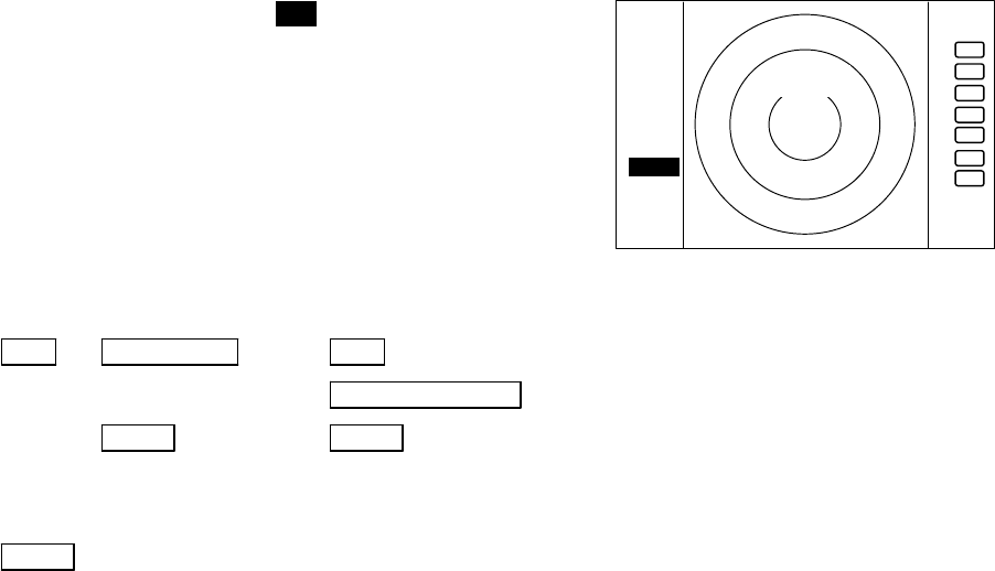
(1) When you press the "GAIN" key, the GAIN display on the left
side of the screen will be reversed as
G 35 , allowing the manual gain adjustment to be effective.
(2) When you turn the control knob either CW or CCW, the figure
will change within a range of 0 through to 99, causing the sen-
sitivity to be manually adjusted. When you press the AUTO
key, GAIN, STC and FTC will be automatically set up to opti-
mized level.
(3) After the adjustment is finished, press the "GAIN" key to exit
from the adjustment mode. If some other function key is
pressed, that function will become effective.
(a) To make adjustments by MANUAL (When the GAIN key is pressed under AUTO operation, shifting to a manual
operation will take place.)
GAIN →Control knob → GAIN --------------------- The adjustment state is ended.
→ Other function key --- Shift to other functions
→AUTO → AUTO -------------------- GAIN, STC, and FTC are set at AUTO and the
adjustment state is ended.
(b) To switch from the MANUAL state
AUTO ---------------------------------------------------------------- Set GAIN, STC and FTC at AUTO
5.3.7 Reducing the sea clutter (STC)
(1) When you press the "STC" key, the STC display on the left side of the screen will be reversed as S 35 , allowing the
STC manual control to be effective.
(2) When you turn the control knob, the figure will change within a range of 0 through to 99, allowing the manual
control STC to be effective. When you press the "AUTO" key, GAIN, STC and FTC will be set to AUTO mode.
(3) After the adjustment is finished, press the "STC" key to exit from the adjustment state. If some other function key
is pressed, that function will become effective.
(a) To make adjustments by MANUAL (When the STC key is pressed under AUTO operation, shift to a manual operation
will take place.)
STC →Control knob → STC ----------------------- The adjustment state is ended.
→ Other function key ----- Shift to other functions
→AUTO → AUTO ---------------------- STC, GAIN, and FTC are set at AUTO and the
adjustment state is ended.
NOTE) When you select MANU (Manual) mode, GAIN and FTC will be switched to MANU (Manual) mode, too.
(b) To switch from the MANUAL state
AUTO ---------------------------------------------------------------- Set STC, GAIN and FTC at AUTO
. 75
.25
HU
G 50
ST’BY
+
36
5.3.8 Removing rain and snow clutter (FTC)
(1) When you press the FTC key, the FTC display on the left side of
the screen will be reversed as F 50 , allowing the manual control
of FTC to be effective.
(2) When you turn the control knob either CW or CCW, the figure
will change within a range of 0 through to 99, changing the
receiver gain. When you press the AUTO key, GAIN, STC and
FTC will be set to AUTO mode.
(3) After the adjustment is finished, press the "FTC" key to exit from
the adjustment mode. If you press some other function key,
shifting to that function will take place.
(a) To make adjustments by MANUAL control (When the FTC key is pressed under AUTO operation, shifting to a
manual operation will take place.)
FTC →Control knob → FTC ---------------------- The adjustment becomes ineffective.
→ Other function key --- Shift to other functions
→AUTO → AUTO -------------------- GAIN, STC, and FTC are set at AUTO and these
functions will become ineffective.
(b) To switch from the MANUAL mode to the AUTO mode
AUTO ---------------------------------------------------------------- Set GAIN, STC and FTC at AUTO
5.3.9 Man Over Board (MOB)
Pressing the MOB key will send the ship's own position data (WPL field in NMEA sentence) to external equipment
through the NMEA port. There is no change on the screen.
To check the MOB position data, select "MOB" from the "WINDOW" menu in the "SETUP". The position of MOB
and current position will be displayed on the screen. If you press the MOB key while watching the MOB screen, the MOB
data will be cleared and the display returns to previous screen. If you press other key, MOB data will remain and the
display returns to previous screen.
5.3.10 Acquisition of a target (ACQ)
Firstly, select the target to track. Place the cursor on the target image and acquire it by pressing the ACQ (acquisi-
tion) key.
Select the target when it is displayed clearly and no other targets are displayed around it. If other targets are displayed
around it, the ATA may track a different one.
All targets acquired by ATA are identified by the numbers, from 0 to 9. These figures will be shown in the upper right
window on the screen. A vacant column shown like "-" indicates no target being acquired.
Before starting selection, use the TGT NUM (target number) key so that "-" is highlighted.
5.3.11 Select target number (TGT NUM)
The TGT NUM key is used to change the target numbers. The target number will not change automatically unless
this function is used.
When ATA starts acquisition, a symbol appears at the cursor position on the screen, and the target number is shown on the
lower right side of the symbol.
. 75
.25
HU
F 50
ST’BY
+

37
5.4 Functions of Soft Keys
xxx = keys to press
< Outline of soft keys >
Any function can be optionally allocated to the key upon which numbers 1-7 are indicated. A maximum of 4 groups of
functions can be allocated to each soft key, and switching between those functions is conducted by the "NEXT" key.
5.4.1 Bearing measurement (EBL1)
(a) Bearing measurement by EBL1
(1) When you press the EBL1 key, the electric bearing line (EBL1) appears and the angle from the direction of the
ship’s head, which is set at 0 o , will appear in a reverse display at the lower left side of the screen (See Note).
(2) Use the control knob to place the direction cursor on the target, and read the angle.
(3) After the setting
i) If you press the EBL1 key, the setting will be completed.
ii) If you press other function key, the function will be shifted to that of the pressed key with the setting condition
still in effect.
note: 1 xxx.x o indicates EBL1.
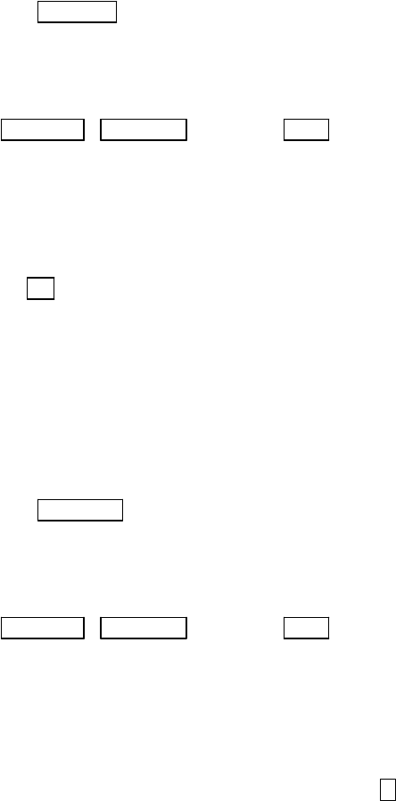
EBL1 → Control knob → EBL1 EBL1 is displayed and the process is finished.
→ Other function key EBL1 is displayed and the function is shifted.
→ EBL1 EBL1 is turned off.(b)
(b) To turn off the EBL1
When you press the EBL1 key, EBL1 will disappear. (EBL1 OFF)
Note: Refer to "5.5.1.1 Bearing measurement (EBL1)".
5.4.2 Bearing measurement (EBL2)
The operation is the same as EBL1. Refer to the EBL1 operation. The EBL2 will appear in a reverse display at
the lower right side of the screen.
5.4.3 Distance measurement (VRM1)
(a) Distance measurement by VRM1
(1) If you press the VRM1 key, a Variable Range Marker 1 (VRM1) will appear and the distance of VRM1 will
appear in a reverse display at the lower left side of the screen.
(2) Place the marker on the front edge of the target with the control knob and read the distance.
(3) After the setting
i) If you press the VRM1 key, the setting will be completed.
ii) If you press other function key, the function will be shifted to that of the pressed key with the setting condition still
kept in effect.
note: 1 xxx.x NM indicates VRM1.
VRM1 → Control knob → VRM1 The VRM1 distance is displayed and the
VRM operation is ineffective.
→ Other function key VRM1 is displayed and the effective function shifts
to other function.
→ VRM1 VRM1 is turned off.(b)
(b) To turn off the VRM1
If you press the VRM1 key, VRM1 disappears. (VRM1 OFF)
Note: Refer to "5.5.1.2 Determining the distance (VRM1)".
38
5.4.4 Distance measurement (VRM2)
The operation is the same as VRM1, refer to VRM1 operation. The "VRM2" will appear in a reverse display at
the lower right side of the screen.
5.4.5 Measuring the angle between two points (FL EBL2)
Note: VRM2 and EBL2 do not follow the OFF-C function while floating.
Note: Refer to "5.5.1.5 Measuring the distance or angle between two points ( FL EBL2, FL VRM2 )".
(a) Setting a reference point for measurement of the angle.
(1) Press "FL EBL2" key. “SET START POINT” is displayed and a small cross mark appears.
FL EBL2 → FL EBL2 is turned ON and
(Select FL EBL2) the small cross mark appears.
(2) Use the left-right and up-down cursor keys to place the small cross mark on one of the two echoes whose angle
will be measured, and press the "ENT" key.
Up/Down &Left/Right → --------- ENT Criterion of the reference point is set.
(Place the cross cursor on an echo)
(b). Measuring
Perform the operations in the above mentioned and "measuring the angle (EBL2)", and place the EBL2 on other
echo.
EBL2 is displayed on the screen referenced by the fixed cross cursor, which is positioned.
The " 2 xxx.x°" will be displayed at the lower right side that shows the angle between the two points.
5.4.6 Measuring the distance between two points (FL VRM2)
Note: Refer to "5.5.1.5 Measuring the distance or angle between two points ( FL EBL2, FL VRM2 )".
(a) Setting a reference point for measurement of the angle.
(1) Press the FL VRM2 key. The “SET START POINT” sign will be displayed and a small cross mark appears.
FL VRM2 → FL VRM2 is turned ON and the small cross mark appears.
(Select FL VRM2)
(2) Use the left-right and up-down cursor keys to place the small cross mark on one of the two echoes whose angle
will be measured, and press the "ENT" key.
Up/Down &Left/Right → --------- ENT Criterion of the reference point is set.
(Place the cross cursor on an echo)
(b) Measuring
Perform the operations mentioned above and "measuring the distance(VRM2)", and put the VRM2 on other echo.
VRM2 is displayed on the screen referenced by the fixed cross cursor, which is positioned.
The distance between two points will be shown like " x. xNM", which is displayed at the lower right side
of the screen.
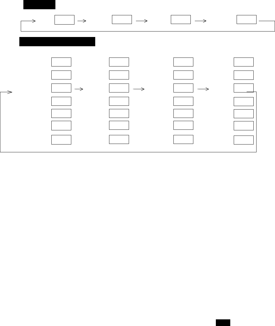
5.4.7 Changing the group of Soft Keys (NEXT)
Any function can be optionally allocated to the key upon which numbers 1-7 are indicated. You can allocate 4
groups of functions at maximum to each soft key, and switch between those functions by the "NEXT" key.
The "NEXT" key switches between allocated function groups on the soft key with numbers 1-7 indicated.
Every time you press the "NEXT" key, function group changes one another. You can also change the function group
using the left-right cursor key, at the "KEY ASSIGNMENT" function in the "CUSTOM" menu of the "SETUP".
2
39
Operation_
_Soft Key Setting Example_
SET1 SET2 SET3 SET4
The function can be changed at the "KEY ASSIGNMENT" function in the "CUSTOM" menu of the "SETUP".
5.4.8 Erasing the Heading Marker temporarily (HDG OFF)
Press the “HDG OFF” key. The heading marker is turned off as long as you press and hold the key.
5.4.9 Using parallel cursors (///CSR)
Press the “///CSR” key. Parallel cursors will appear on the screen. As you rotate EBL, the parallel cursors also rotates
in synchronism with EBL.
To cancel the "///CSR" function, press "///CSR" key once more.
Note: Refer to "5.5.1.8 Using parallel cursors (///CSR)".
5.4.10 Establishment of the indication of the RANGE RINGS (RINGS)
Press the “RINGS” key. Range Rings will appear on the screen. To cancel the "RINGS" function, press "RINGS"
key once more.
Note: Refer to "5.5.1.9 Establishment of the indication of the RANGE RINGS (RINGS)".
5.4.11 ON/OFF of variable range function (VAR RNG)
The range scales are allocated as standard in steps of 0.5--0.75--1.5--3.0--.....(STEP mode), but using this function
you can set up the scaling to be more closely separated, such as 0.5--0.6--0.7--0.8--..... (CONTINUOUS mode).
Press the “VAR RNG” key. The VAR RNG function becomes valid and the sign VAR appears at the upper left side
of the screen (beside MODE). To cancel the "VAR RNG" function, press the VAR RNG key again.
To change the range scale in the CONTINUOUS mode, use the up-down cursor while the VAR RNG function is on.
To change the range scale in the STEP mode, press the "RANGE UP" or "RANGE DOWN" key.
If you press other keys, the relevant key function becomes effective with current VAR RNG function being acti-
vated.
5.4.12 Changing display modes (MODE)
(1) Select MODE from the pull-down display items using the up-down cursor keys, and press the "ENT" key.
(2) When the HU/HS/NU/CU/TM sign is displayed beside the MODE item, select display mode with the up-down cursor
keys and press the "ENT" key.
(3) The setting completes when you press the ENT key after the selection. (NOTE1,2)
Press the "MODE" key, the display mode will change on every press of the key to HU (Head Up), HS , NU, CU, TM
in order. The words MODE SELECT appear at the upper part of the screen. However, a setting will be needed for the
ship’s speed if TM is selected. Also, a heading or a course information is necessary for NU, CU and TM.
1
3
4
5
2
1
3
4
5
2
1
3
4
5
2
6 6
6
EBL1
VAR RNG
TRACK
TARGET
VRM1
EBL2
FL EBL2
FL VRM2
GZ
VRM2
DATA
ALL-DEL
TRACK
ZOOM
DEL
SEL WIN
OFF-C
PICTURE
7
7
7
NEXT
NEXT NEXT
1
3
4
5
2
6
PPI
PPI/PPI
PPI/NAV
ALL PPI
PPI/3D
ALL PPI2
7
NEXT
7
7
7
NEXT
NEXT
NEXT
7
NEXT

40
note: TM is valid on PPI screen only. The mode will change to NU on the other screen automatically.
Note: Refer to "5.5.2.1 Changing display mode (MODE)".
5.4.13 Guard Zone (GZ)
A function that sets a guard zone of any distance and any angle range, creating an alarm tone when either echoes
above a certain level exist (IN MODE) or no echoes exist(OUT MODE).
When you activate the GZ function with soft keys, the guard zone and ON/OFF settings can be made, however, the
guard zone mode (IN or OUT) must be set in the menu.
Note: Refer to "5.5.2.2 Guard Zone (GZ)".
(1) When you press the "GZ" key, the present mode setting will be displayed on the left side of the screen shown as GZ
IN. A small cross cursor for setting the guard zone will be displayed on the screen center while "SET CENTER
POINT" is displayed at the bottom, activating a guard zone setting state.
(2) Use the up-down/left-right cursor keys to move the cross cursor to the center of the warning zone to be set, and press
the "ENT" key.
(3) From the cross cursor position set in (2) above as the center, expand the guard zone towards further out of the range
with the up cursor key, and towards azimuth, use the right cursor key, thus forming a fan-shaped guard zone. To make
the warning zone smaller, press the down cursor key to reduce the range and press the left cursor key to reduce the
azimuth angle.
(4) Press the "ENT" key to fix the settings.
Press the GZ key twice to cancel the guard zone function.
GZ → Up/Down &Left/Right → ENT → Up/Down &Left/Right → ENT Setting completed
(Setting the center of GZ) (Setting the scope of GZ)
→ GZ -------------------------------------------------------------------------------------------Canceling GZ
<Silencing the audio alarm>
Press the "MENU" key or "ENT" key to silence the beep.
NOTE: Set the mode (IN or OUT) at the "GZ MODE" of the "PRESET2" function in the "CUSTOM" menu of the
"SETUP"
Set the alarm level (IN or OUT) at the "GZ LVL" of the "PRESET2" function in the "CUSTOM" menu of the
"SETUP"
5.4.14 Off Center (OFF-C)
Own ship position can be offset to any desired point designated by the cross cursor within the screen.
Note: Refer to "5.5.2.3 Shifting display in specific direction (OFF-C)".
(1) When you press the "OFF-C" key, the sign OFF-C will be displayed in the upper right corner of the screen and "SET
OFF CENTER POINT" at the bottom of the screen, and setting is ready to be entered.
(2) Move the cross cursor with the cursor keys to move own ship’s position to an intended location, and press the "ENT"
key. Own ship’s position will be offset to the point as designated by the cursor. OFF-C is displayed in the upper
right corner of the screen, indicating the "OFF-C" state is entered.
(3) To cancel "OFF-C" function, press the "OFF-C" key.
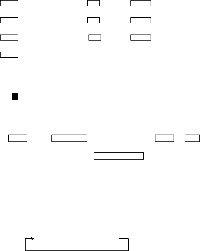
(a) To set off-centering point, press relevant keys as follows:
OFF-C → Up/Down & Left/Right → ENT --------------- Fixes the off-centering point and exit the
off-centering state.
Note: VRM2 and EBL2 do not follow the off-centered picture
while they are floated. The function operates on PPI
screen only.
(b) To cancel the OFF-C function, press the OFF-C key again.
OFF-C The "OFF-C" display at the upper right disappears and function
returns to the ordinary state from the Off Center state.
41
5.4.15 Setting of the SLEEP function (SLEEP)
This function allows the transmitter to transmit 30-seconds during pre-fixed hours. After a transmission, a
power-saving mode is entered with the screen put into the ST'BY mode (the scanner is kept OFF state) and the LCD
backlight lamp is turned off. This action is repeatedly executed.
For example, set a guard zone and set the warning signal automatically confirmed every prefixed period.
Press the "SLEEP" key to set up the sleep period. Every press of the key sets up the "SLEEP" time every 5 minutes
like, 5-minutes, 10-minutes, 15-minutes, and off.
When a transmission takes place after setting a SLEEP mode, a ST'BY state is entered and the backlight turns off
after a 30-second-transmission. (Power-saving mode). Two minutes before the fixed time the backlight turns on and the
2-minute timer starts. Then, at the fixed time another 30-second-transmission begins. This series of actions repeats. If
any one key is pressed during the course of this action, the SLEEP function will be canceled.
Note: Refer to "5.5.2.4 Setting of the SLEEP function(SLEEP)".
(1) Setting procedure
SLEEP → (Select 5min.) → ENT → POWER -------------------→ 30-second-transmission every 5 min.
→ transmission ON
SLEEP → (Select 10min.) → ENT → POWER ------------------→30-second-transmission every 10 min.
→ transmission ON
SLEEP → (Select 15min.) → ENT → POWER ------------------→30-second-transmission every 15 min.
→ transmission ON
SLEEP → (Select OFF) ---------------------------- SLEEP function is turned OFF
Setting completed
5.4.16 Tuning adjustment (TUNE)
(1) When you press the "TUNE" key, the TUNE display on the upper-right side of the screen will be reversed as
35 and the adjustable state will be entered.
(2) When you rotate the rotary control, the figure changes within a range of 0 through to 99, allowing the re-
ceiver tuning be manually adjusted.
(3) After the adjustment is finished, press the "ENT" key to exit from the adjustment state. If some other
function key is pressed, shift to that function will take place.
TUNE → Control knob → --------------------- TUNE or ENT The adjustment state is
ended.
(tuning adjustment) → Other function key --- Shift to other functions
Note: Use the "MENU" to return auto-tuning state.
Note: Refer to "5.5.3.4 Adjusting receiver tuning (TUNE)".
5.4.17 Echo expansion (ST)
Expanding the echo to the direction of the distance.
When you press the "ST" key, the sign "ST1" will be displayed on the left side of the screen, causing the echoes to be
stretched towards range. Two types of echo expansion are available,
Note: Refer to "5.5.3.5 Echo expansion (ST)".
ST1 → ST2 → OFF
(Expansion rate ST1 < ST2 )
Note: The "OFF" state is not displayed on the screen and the "ST2" display disappears.
5.4.18 Displaying ship’s track (TRACK)
When you press the "TRACK" key, "TK 15SEC" will be shown on the left side of the screen, causing the track mode
to be available. The sign “15S” indicates the length of the track, and displays a maximum of 15-second-long sailing track.
Note: Refer to "5.5.3.6 Displaying track of target (TRACK)".
Every press of the “TRACK” key changes the plotting time of ship’s track as follows.

42
15 sec → 30 sec → 1 min → 3 min → 6 min → CONT → OFF
Note: The "OFF" state will not be displayed on the screen and the "TK xx " display will disappear.
5.4.19 Enlarging selected areas (ZOOM)
The video image shown around the cross cursor can be zoomed twice as large as normal one on the screen.
Press the "ZOOM" key to "ZOOM" ON. A small cross cursor and the sign "SET ZOOM POINT" will be displayed on the
screen center and at the bottom respectively, and the magnification point is to be set. Use cursor keys to move the cross
cursor to the point to be magnified and press the "ENT" key to complete the settings. The area around the cross cursor is
displayed in 2x magnification, with blinking "ZOOM" displayed at the screen upper right, indicating that a ZOOM dis-
play is being conducted.
To cancel the ZOOM function, press the "ZOOM" key again or change the range scale.
Note: Refer to "5.5.3.7 Enlarging selected areas (ZOOM)".
ZOOM → Up/Down &Left/Right →ENT --------------- ZOOM setting
(Move cross cursor)
→ (Select OFF) →ZOOM ZOOM canceled
Note1: VRM2 and EBL2 do not follow the ZOOM function during a floating state.
Note2: Normal screen returns when you change the range scale.
Note3: ZOOM function is unusable in 3D/PPI screen.
Note4: ZOOM function is unusable in OFF-C.
Note5: Center of ZOOM can be set to any desired position within the set range.
5.4.20 Increasing sensitivity (S/L)
The transmitting pulse length is automatically set as you change the range scale. However, on certain range scales, you
have an option to select the pulse length to shorter or longer pulse length. Select the pulse length according to the navi-
gational situation you are facing, shorter pulse lengths for better picture definition and longer pulse lengths for better
range performance. As an adverse effect, the shorter pulse lengths may sacrifice the range performance and in turn, the
longer pulse lengths lose the picture clarity compared with those selected as standard.
Press the "S/L" key to select the Pulse length (LONG or SHORT). The pulse length changes L (Long) and S (Short)
alternately.
Note: Refer to "5.5.3.8 Increasing the sensitivity (S/L)".
S/L → (Select SHORT) → Set to short pulse
→ or (Select LONG) → Set to long pulse
5.4.21 Switching the screen (SEL WIN)
On the PPI+PPI mode display, you need to select an activated screen first for subsequent key operations like range scale,
GAIN, STC, FTC, VRM and EBL.
For example, you want to change the range scale on the PPI+PPI screen. Press the “SEL WIN” key to select an active
screen. The range scale display will be reversed as a result, showing the screen is active. Press the UP or DOWN key to
change the range.
Note: Refer to "5.5.4.2 Switching screens on PPI/PPI screen ( SEL WIN )".
SEL WIN → (Select right screen) → Right screen activated
→ or (Select left screen) → Left screen activated
43
5.4.22 Changing the color of screen (PICTURE)
The display color can be changed according to daytime or nighttime operations. Press the "PICTURE " key to change the
color.
Note: Refer to "5.5.4.3 Changing the color of screen (PICTURE)".
5.4.23 Change to PPI screen ( PPI )
Press the "PPI" key to change the screen to the standard single PPI screen.
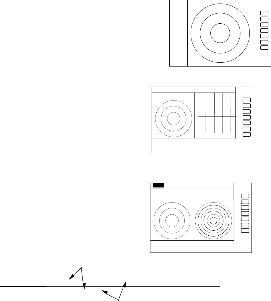
5.4.24 Change to SEMI3D/PPI screen ( SEMI3D )
Press the "SEMI3D" key to change the screen from other modes to the
SEMI3D/PPI screen.
Note: All controls, such as EBLs, VRMs are operative on both screens.
The ZOOM, OFF-C, FL EBL2, and FL VRM2 could not
be used on this mode. On the "SEMI3D" screen, the vertical center
index line marked “000” indicates ship's heading direction.
5.4.25 Change to PPI/PPI screen ( PPI/PPI )
Press the "PPI/PPI" key to change the current screen to the PPI/PPI
screen.
Note:
(1) Each radar picture is refreshed alternately. Right screen picture is
held frozen while the left screen is updated, left screen held during the
right screen refreshing. Therefore, each screen is updated every 2
antenna revolutions.
LEFT screen /---------/********/---------/********/---------/******** time→
RIGHT screen ********/---------/********/---------/********/---------/
(2) The ZOOM, OFF-C, FL EBL2, and FL VRM2 are inoperative in this mode.
(3) The range, GAIN, STC, FTC, GZ can be used independently in active display as selected by the "SEL WIN" key.
(4) The cross cursor can be controlled in an active display.
refreshing radar picture
holding previous picture
. 75
.25
HU
+
PPI screen
.75
.25 HU S
+
280 320 000 040 080
SEMI3D/PPI screen
.75
.25 HU S
24
6
+
G 55/35
S 35/AT
F 35/AT
PPI/PPI screen
44
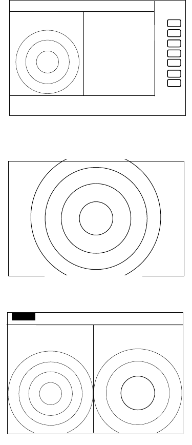
5.4.26 Change to PPI/NAV screen ( PPI/NAV )
Press the "PPI/NAV" key to change current screen mode to PPI/NAV
screen mode.
Note: The ZOOM, OFF-C, FL EBL2, and FL VRM2 can not be used in
this mode.
5.4.27 Change to ALL PPI screen ( ALL PPI )
Press the "ALL PPI" key to change the current screen mode to ALL PPI
screen mode.
Note:
(1) The range scale, rings interval and the display mode are shown in
the upper left corner of the screen.
(2) Return to PPI screen mode pressing a key except MENU, range UP
or DOWN, or POWER key.
5.4.28 Change to ALL PPI/PPI screen ( ALL PPI2 )
Press the "ALL PPI2" key, the screen will change to ALL
PPI/PPI screen.
Use to change the screen from other modes to ALL PPI/PPI.
Note:
(1) The range, rings interval, display mode are displayed on the upper
left of each screen.
(2) Return to PPI/PPI screen mode pressing a key except MENU,
range UP or DOWN, or POWER key.
(3) Each radar picture is refreshed alternately. Right screen
picture is held frozen while the left screen is updated, and vice
versa. The picture update is therefore taking place every 2 antenna revolutions. When your ship navigates at
high speed, use the PPI screen mode to allow fast refreshing pictures.
5.4.29 Canceling target tracking (DEL)
To cancel tracking, use the DEL (delete) function. The number highlighted on the upper right of the screen will
disappear. If ALL DEL (delete all) is selected, the ATA will cancel tracking of all targets.
Press the soft key if the DEL function has been set.
When operating from the MENU, place the cursor on NAVI/DEL and press the ENT key. When the radar is set to the
SY'BY mode, the ATA will cancel tracking of all targets.
5.4.30 Canceling all target tracking (ALL DEL)
To cancel tracking all target, use the ALL DEL (All delete) function. The number highlighted on the upper right of
the screen will disappear.
Press the soft key if the ALL DEL function has been set.
When operating from the MENU, place the cursor on NAVI/ALL DEL and press the ENT key. When the radar is set to
the SY'BY mode, the ATA will cancel tracking of all targets.
5.4.31 Data display (DATA)
When necessary, numerical data of the current tracking target can be displayed in the data display window. Use
the DATA function to display the numerical data of the number highlighted on the upper right corner of the screen.
Press the soft key if the DATA function has been set.
.75
.25 HU s
+
NAV DISPLAY
WAY P 123.4°
6.8NM
COURSE 2.38NM
XTE <<<<
HDG 267.3°T
SPD 12.8KT
TEMP 20.8°C
DEPTH 58.3M
LAT/LON
34° 08. 22N
138° 02 .53E
PPI/NAV screen
.75
.25
HU
+
ALL PPI
screen
.75
.25 HU S
.25 .
125
+
ALL PPI/PPI
screen
45
When operating from the MENU, place the cursor on NAVI/DATA and press the ENT key.
Items to be displayed are as follows.
Target number: TGT NO.x The number of the target currently displayed.
Vector time: TIME xx MIN. Setting time to display vector length. (Speed x Time=vector length)
Vector mode: TRUE or REL Display mode of vector and data. TRUE and REL represent true and relative speeds,
respectively.
Target data:
BRG (bearing), DIST (distance), CRS (course), SPD (speed), CPA (closest point of approach) and TCPA (time required
for the ship to reach the CPA)
State: A collision or lost alarm will appear according to the state of the target.
Example:
-------------------------------------------------------------------------------------------------------------
| TGT No.x ALM LOST TIME xxMIN TRUE |
-------------------------------------------------------------------------------------------------------------
| BRG 123.4DEG CRS 234.5DEG CPA 12.3NM |
| DIST 12.3NM SPD 10.0KT TCPA 12.3MIN |
-------------------------------------------------------------------------------------------------------------