Koden Electronics RB718A Marine Radar RA54 User Manual OME RA5354 3of4
Koden Electronics Co., Ltd Marine Radar RA54 OME RA5354 3of4
Contents
- 1. Manual1of4
- 2. Manual2of4
- 3. Manual3of4
- 4. Manual4of4
Manual3of4
46
5.5 MENU Operation
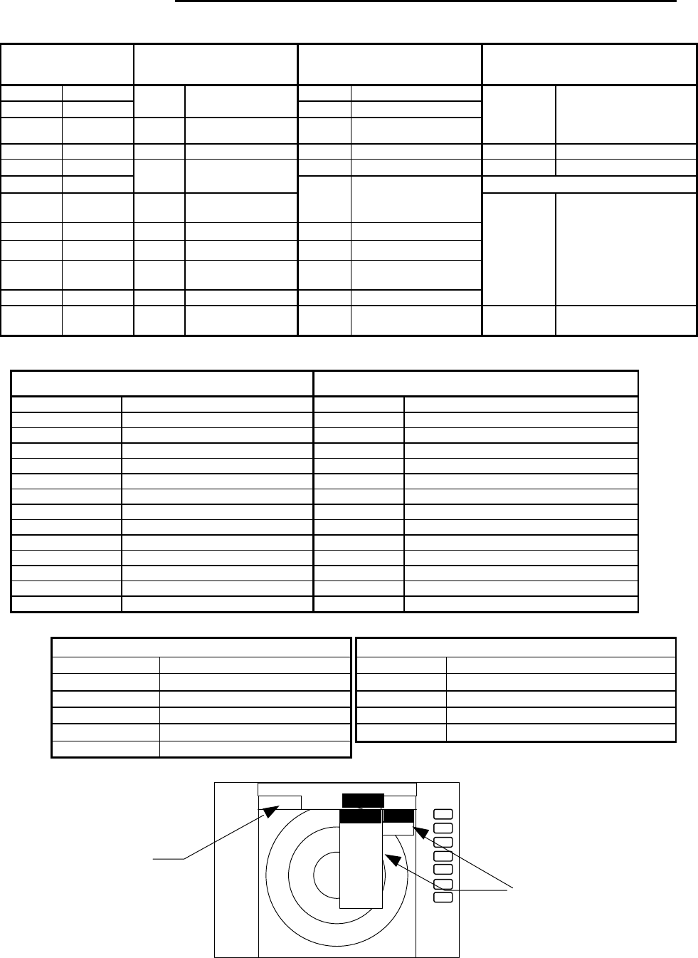
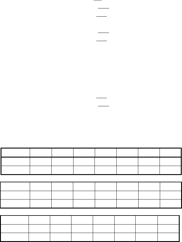
List of MENU
List of Main Menu
MARK
(MAIN-MENU)
NAV
(MAIN-MENU) ECHO
(MAIN-MENU) SETUP
(MAIN-MENU)
EBL1 ON/OFF GAIN AUTO/MAN
VRM1 ON/OFF
MODE
HU/HS/NU/CU/TM
(MANU/NMEA) STC AUTO/MAN/HARBOR
EBL2 ON/OFF GZ ON/OFF FTC AUTO/MAN
WINDOW PPI / SEMI3D+PPI /
PPI+PPI / PPI+NAV /
ALL PPI /
ALL PPI+PPI / MOB
VRM2 ON/OFF OFF-C
ON/OFF TUNE AUTO/MAN SEL WIN
FL EBL2
ON/OFF ST OFF/ST1/ST2 PICTURE DAY/NIGHT
FL VRM2
ON/OFF
SLEEP
OFF/5min/10min/
15min SYSTEM CHECK
HDG
OFF
OFF
TRACK
OFF/15SEC/30SEC/
1MIN/3MIN/6MIN/
CONT
///CSR ON/OFF ZOOM
ON/OFF
RINGS ON/OFF SL SHORT/LONG
VAR
RNG
ON/OFF
TARGET
CUSTOM KEY ASSIGNMENT
PRESET1 (SUB-MENU)
PRESET2 (SUB-MENU)
NMEA PRESET
ADJUST (SUB-MENU)
+MK
LINE
ON/OFF
List of Custom Menu
PRESET1 (SUB-MENU) PRESET2 (SUB-MENU)
HM FLSH ON/OFF GZ LEVEL 1-7
STERN M ON/OFF GZ MODE IN/OUT
NORTH M ON/OFF HOLD ON/OFF
ST’BY NAVI/NOR DISPLAY RDR/MONI/NAV
BUZ VOL OFF/LOW/HIGH EXT BUZ OFF / CONT / INT
RM UNIT NM / KM / SM IN P/R 1080/1024/2048/4096/360
DEPTH M / FT / FM OUT P/R 1080/1024/2048/4096/360
TEMP °C / F DEMO ON / OFF
EBL BRG REL / TRUE / MAG IR OFF / IR1 / IR2
WP BRG TRUE / MAG SPD SET NMEA / MANU 0.0 KT / LOG 200P
HEAD INPUT NMEA / SIN, COS /12BIT / 10BIT
LANGUAGE 15 countries
HEAD TRUE / MAG SCAN SPEED
STD / HIGH
+MK MODE DIST/BRG / LAT/LON
P TABLE 0 - 2
ADJUST (SUB-MENU)
TIMING ADJ
HEAD ADJ
TUNING CAL.
ANTENNA 1-9
GAIN 1-30
STC 1-16
ATA PRESET
CPA SET 0.0 NM
TCPA SET 0 MIN
VECT SET. 6 MIN
VECT MODE
REL/TRUE
ATA ON/OFF
+
ST’BY
.75
. 25
HU
STC >
FTC >
TUNE >
ST >
TRACK
ZOOM
S/L
MARK
NAV
ECHO SETUP
ECHO
GAIN >
MANU
AUTO
MAIN-MENU
SUB-MENU
47
5.5.1 Mark Menu xxx = keys to press
Setting for markers and cursors
<Common operations for the MARK menu>
(Up to the point when "MARK" menu is selected from the main menu)
Press the "MENU" key and select "MARK" from the displayed 4 main menus using the left-right cursor.
(The contents of the selected MENU will appear on a pull-down display in accordance with the movement of
the left-right cursor.)
MENU → Left/Right
(Select MARK)
Further explanations on the MARK menu are made assuming that "common operation for the MARK
menu" has already been completed.
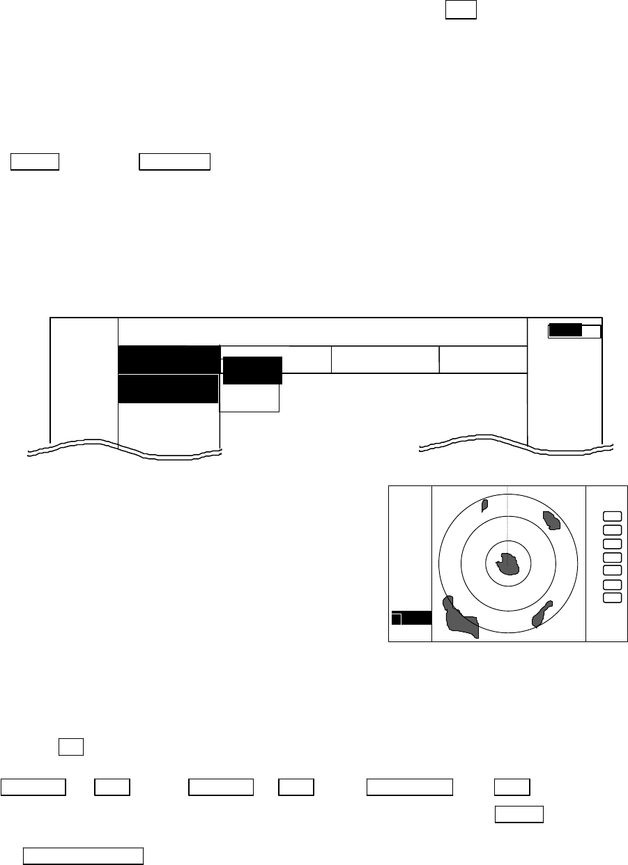
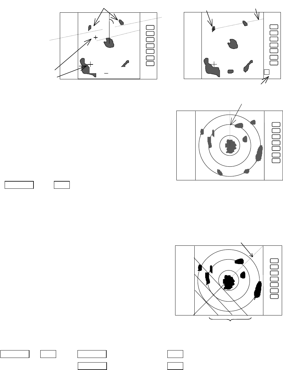
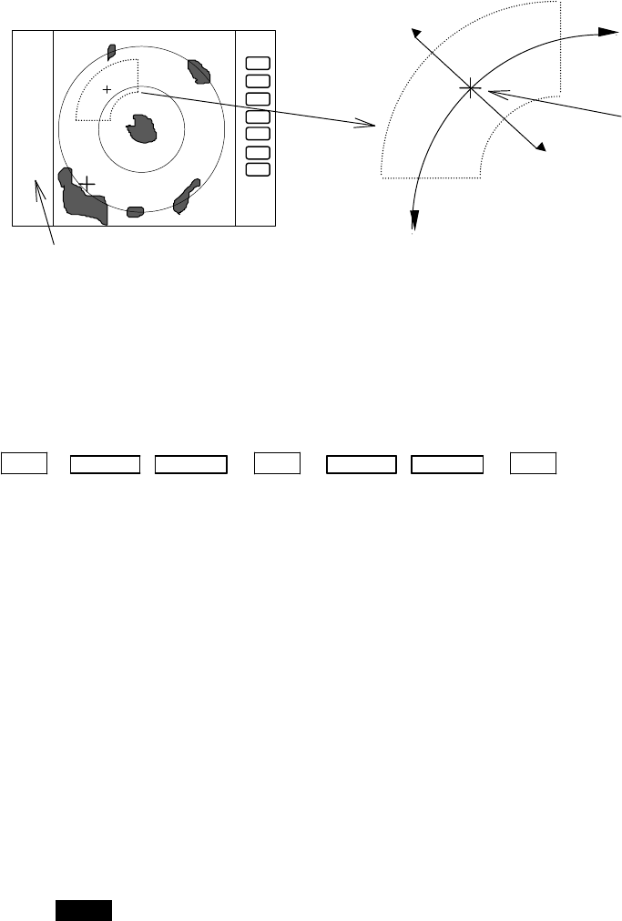
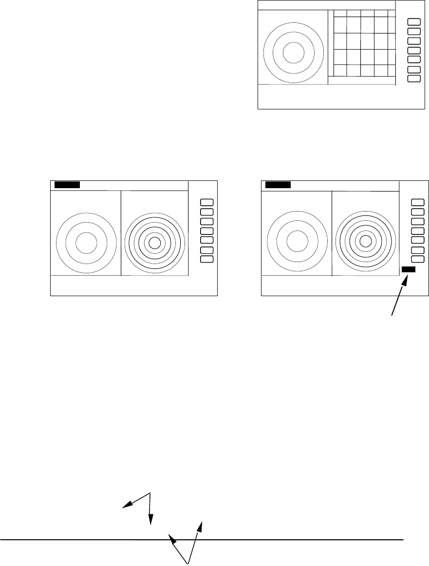
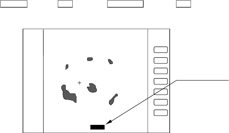
5.5.1.1 Bearing measurement (EBL1)
(1) Select EBL1 from the pull-down display items using the up-down cursor key, and press the "ENT" key.
(2) When the ON/OFF sign is displayed beside the letters EBL1, select ON with the up-down cursor keys and
press the "ENT" key.
(3) When you press the "ENT" key, an electric bearing
line (EBL1) appears and the angle from the direc-
tion of the ship’s head which is set at 0 degree will
appear in a reverse display in the lower left corner
of the screen.
(4) Place the EBL on the center of the target with the
rotary control and read out the bearing. You can use
the EBL functions in the following modes.
(a) Press the "ENT" key to show the EBL1 display still
on the screen.
(b) Press the "MENU" key without the EBL1 display.
(c) Pressing another function key will lead to the function of that key with the EBL1 display still on the
screen.
Note: 1 xxx.x indicates the relative bearing measured by BL1.
Up/Down → ENT → Up/Down → ENT → Control knob →ENT (a)
(Select EBL1) (Select ON) (EBL1 operation) →MENU (b)
→Other function key (c)
Note: The displayed EBL angle is the relative bearing to ship’s heading or true bearing against true
north, depending on the setting of "EBL BRG" in the "SETUP" menu.
MARK
EBL1 >
VRM1 >
EBL2 >
.75
.25
HU NAV ECHO SETUP
MARK
>>>
0.23NM
AT
. 75
.25
HU
+
1 0.0
°
OFF
ON
48
5.5.1.2 Determining the distance (VRM1)
(1) Select VRM1 from the pull-down display items using the
up-down cursor key, and press the "ENT" key.
(2) When the ON/OFF sign is displayed beside the letters VRM1,
select ON with the up-down cursor keys and press the "ENT"
key.
(3) If you press the "ENT" key, the variable range marker1 (VRM1)
and its distance in a reverse display appear in the lower left
corner of the screen (See Note).
(4) To measure the distance to a target, place the VRM1 on the front edge of the target with the rotary
control and read the distance.
(5) You can use the VRM1 functions in the following modes.
(a) Press the "ENT" key to show the VRM1 display still on the screen
(b) Press the "MENU" key without the VRM1 display.
(c) Pressing another function key will lead to the function of that key with the VRM1 display still on
the screen.
Up/Down →ENT →Up/Down → ENT →Control knob → ENT (a)
(Select VRM1) (Select ON) (VRM1 operation) → MENU (b)
→ Other function key (c)
Note: 1 xx.xx NM indicates VRM1.
5.5.1.3 Bearing measurement (EBL2)
Refer to the section “Bearing measurement (EBL1)”.
The "EBL2" will appear in a reverse display in the lower right corner of the screen.
Note: 2 xxx.x indicates the bearing measured by EBL2.
5.5.1.4 Determining the distance (VRM2)
Refer to the section “Determining the distance (VRM1)”.
The "VRM2" will appear in a reverse display at the lower right corner of the screen.
Note: 2 xx.xx NM indicates the distance measured by VRM2.
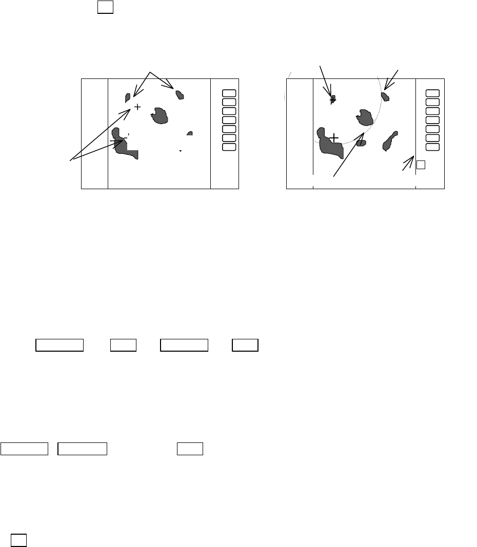
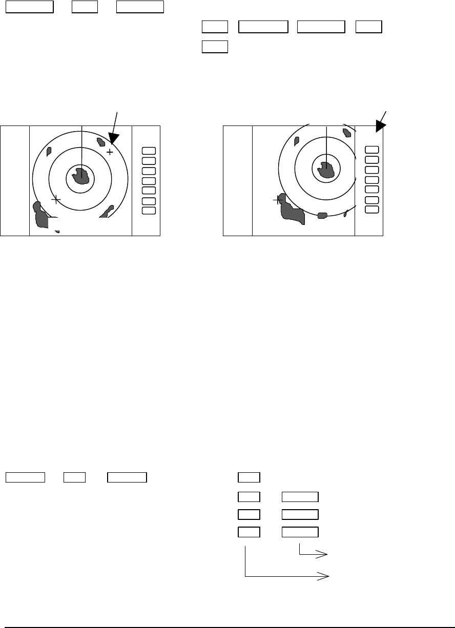
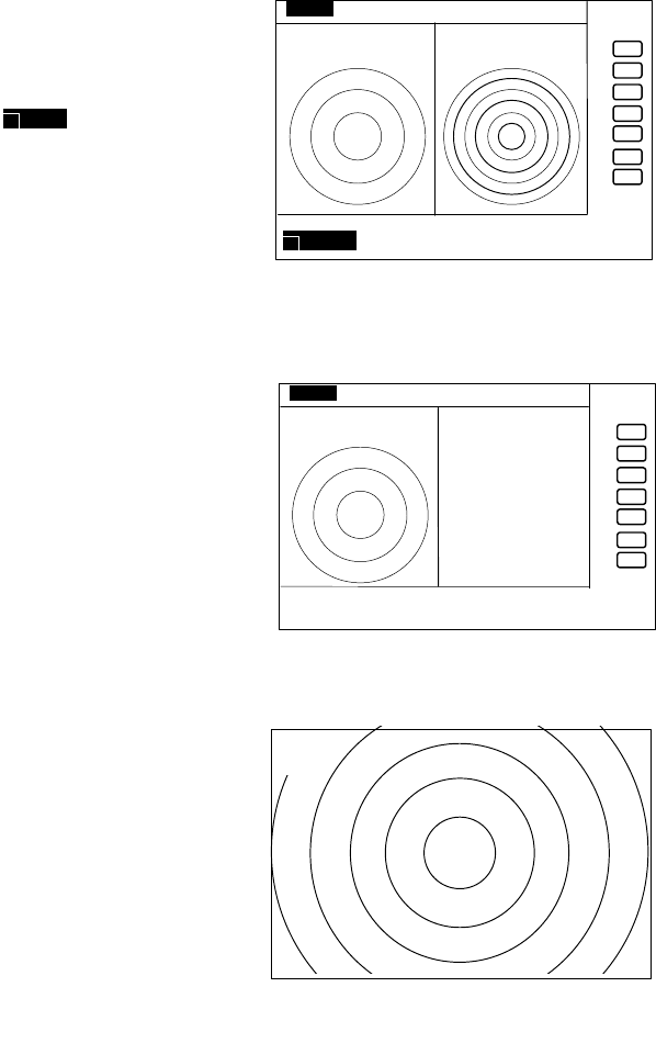
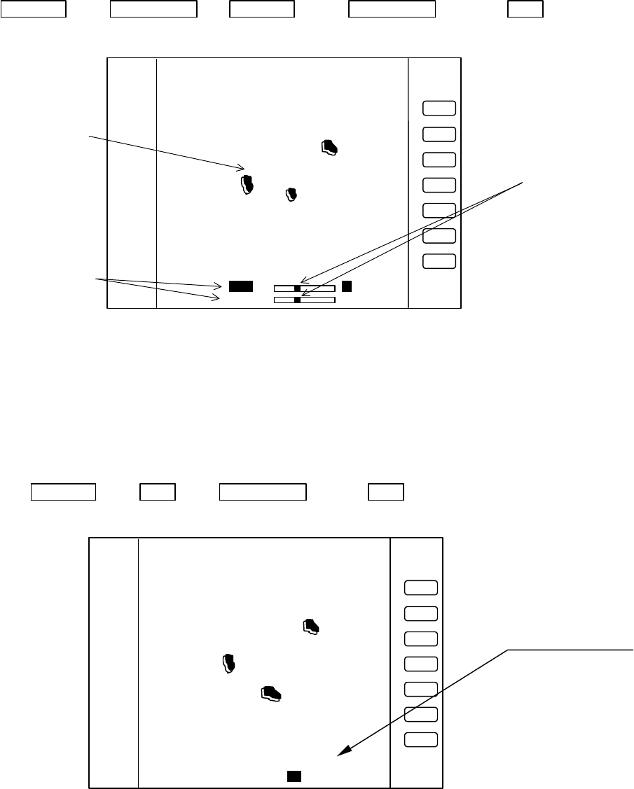
5.5.1.5 Measuring the distance or angle between two points ( FL EBL2, FL VRM2 )
Determining the distance (VRM2)
(a) Preparation for the measurement
(1) Use the up-down cursor keys to select FL VRM2 from the pull-down display items, and press the
"ENT" key.
(2) Use the up-down cursor keys to select ON from the ON/OFF display beside the FL VRM2 items,
and press the "ENT" key. The “SET START POINT” item will be shown and a small cross mark
appears. (Once this is set, the "ON" state continues unless any other change is made.)
Up/Down → ENT → Up/Down → ENT ----------------------- FL VRM2 is turned
ON and the small cross
(Select FL VRM2) (Select ON) mark appears.
(b) Setting a reference point for the distance measurement
Use the left-right and up-down cursor keys to place the small cross mark on one of the two echoes
whose distance is to be measured, and press the "ENT" key.
Up/Down &Left/Right →----------------------- ENT Criterion of the reference point
is set.
(Place the cross cursor on an echo)
.75
.25
HU
+
1 0.00NM
49
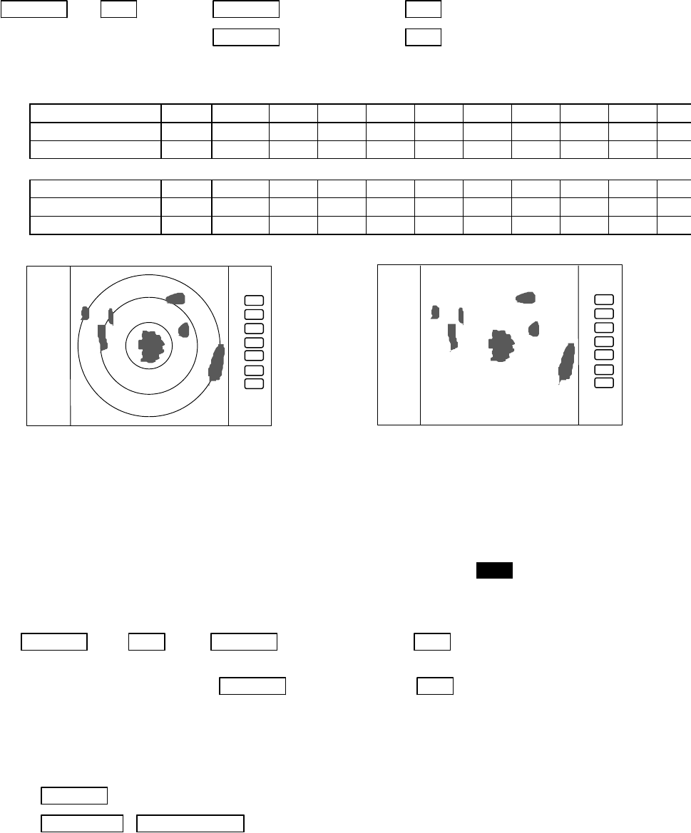
(c) Measuring
Perform the operations in the above mentioned "Common operation for the MARK menu" and
"measuring the distance(VRM2)", and place the VRM2 on other target.
VRM2 will be shown on the screen around the fixed cross cursor.
The distance display " 2 xx. NM" will be shown in the lower right corner of the screen, showing the
distance between the two targets.
Note: EBL2 and VRM2 does not follow to "ZOOM" and "OFF-C" function.
5.5.1.6 Measuring the angle between two points (FL EBL2)
(a) Preparation for the measurement
(1) Use the up-down cursor keys to select FL EBL2 from the pull-down display items, and press the
"ENT" key.
(2) Use the up-down cursor keys to select ON from the ON/OFF display beside the FL EBL2 items, and
press the "ENT" key. “SET START POINT” is displayed and a small cross mark appears. (Once
this is set, the "ON" state continues unless changes are made.)
Up/Down → ENT → Up/Down → ENT ---------------------- FL EBL2 is turned
ON and
(Select FL EBL2) (Select ON) the small cross
mark appears.
(b) Setting a reference point for measurement of the angle.
Use the left-right and up-down cursor keys to place the small cross mark on one of the two echoes
whose angle will be measured, and press the "ENT" key.
Up/Down &Left/Right → -------- ENT Criterion of the reference point is set.
(Place the cross cursor on an echo)
(c) Measuring
Perform the operations in the above mentioned "Common operation for the MARK menu" and
"measuring the distance(EBL2)", and place the EBL2 on other echo.
EBL2 is displayed on the screen based on the placed fixed cross cursor.
" 2 xx. xx" which is displayed at the lower right will be the angle between the two points.
Note: The displayed EBL angle is relative to heading or true to north, depends on the setting of "EBL
BRG" in the "SETUP" menu.
.75
.25
HU
2 0.72NM
Place the VRM2 on other target
SET START POINT
.75
.25
HU
To measure the distance
between two targets
Small cross
mark
FL VRM2 Indication of VRM2
Center of VRM2
50
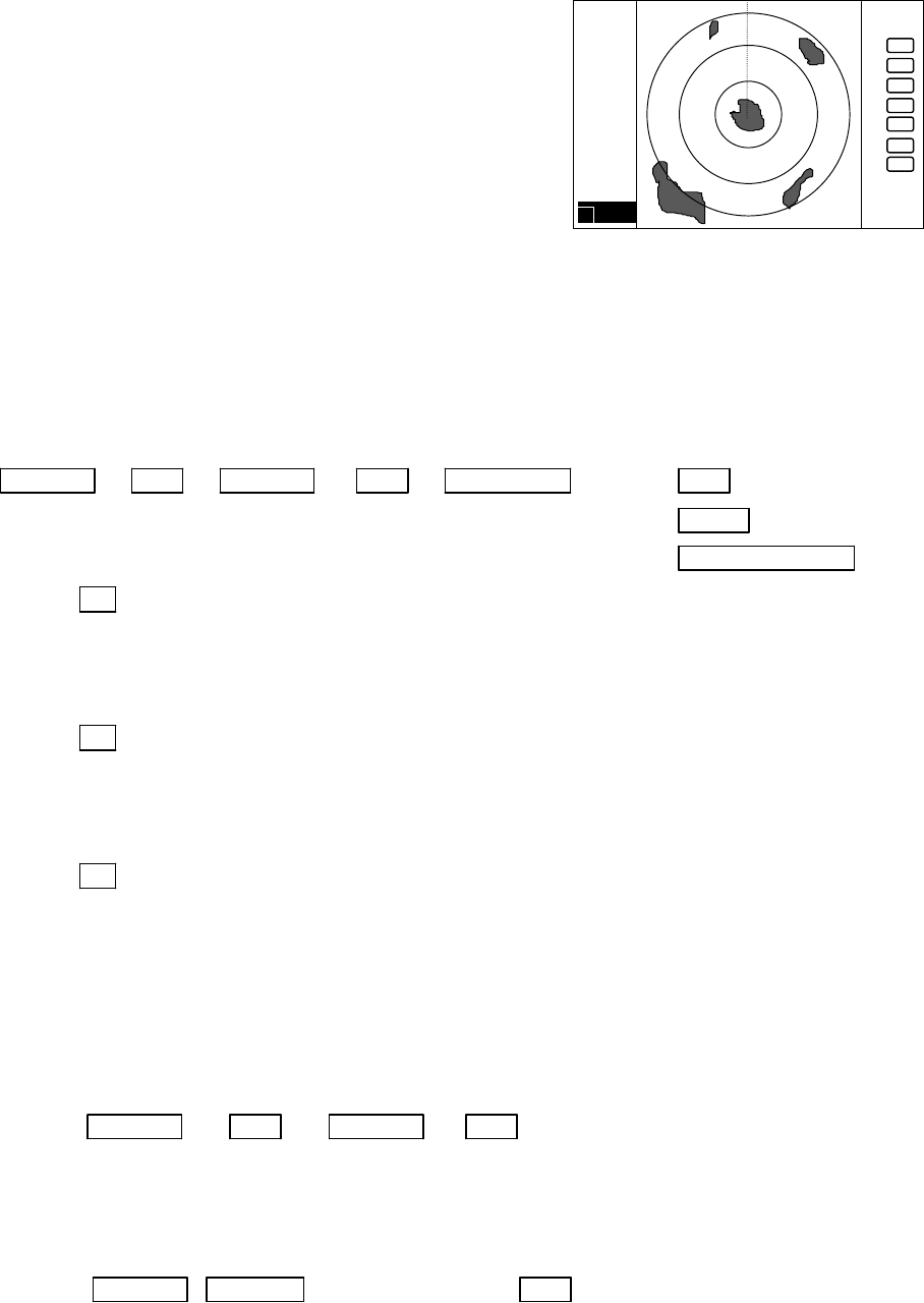
5.5.1.7 Erasing heading marker temporarily (HDG OFF)
(1) Use the up-down cursor key to select HDG OFF
from the pulled down menu.
(2) Press the “ENT” key to turn off the heading marker,
it stays off as long as you press and hold the key.
Up/Down → ENT The heading marker is off as long as you press and hold the “ENT” key down.
(Select HDG OFF)
5.5.1.8 Using parallel cursor (///CSR)
Using the parallel cursor, you can monitor the behavior of other targets whether they are navigating
along with the course or, changing their course to someway.
(1) Use the up-down cursor key to select ///CSR from the
pull-down menu, and press the “ENT” key (ON/OFF
display beside the ///CSR item).
(2) Use the up-down cursor key to select ON.
(3) Press the “ENT” key. Parallel cursor will appear on the
screen. As you move EBL, the parallel cursor also
moves.
To cancel the ///CSR function, select OFF in (2).
Up/Down → ENT → Up/Down (Select ON) → ENT ----------------Parallel cursor appears.
(Select ///CSR) → Up/Down (Select OFF) → ENT ------------ Parallel cursor disappears.
Note: Interval of ///CSR same as fixed range marker.
///CSR moves with EBL1.
.75
.25
HU
Not displayed while the ENT key
is held down.
.75
.25
HU
2 20.3°
FL EBL2
SET START POINT
.75
.25
HU
Origin of EBL2
To measure the angle between two
points
indication of
EBL2
small cross mark
cross mark
.75
.25
HU
EBL1
Parallel cursor
51
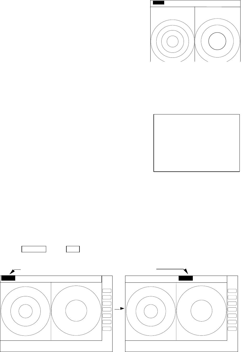
5.5.1.9 Establishment of the indication of the RANGE RINGS (RINGS)
(1) Press the up-down cursor key to select RINGS from the pull-down menu, and then press the “ENT” key.
(The ON/OFF sign will appear beside the letters RINGS)
(2) Use the up-down key to select ON or OFF and press the “ENT” key
Select ON Range Rings ON
Select OFF Range rings OFF
Up/Down → ENT → Up/Down (Select ON) → ENT -------------Range rings appear.
(Select RINGS) → Up/Down (Select OFF) → ENT ---------Range rings disappear.
<Number of range rings and range interval>
RA53
Range 0.125
0.25 0.5 0.75
1.5 3 6 12 24 48 64
Number of Rings 2 2 2 3 6 6 6 6 6 6 4
Interval 0.0625
0.125 0.25
0.25
0.25
0.5 1 2 4 8 16
RA54
Range 0.125
0.25 0.5 0.75
1.5 3 6 12 24 48 72
Number of Rings 2 2 2 3 6 6 6 6 6 6 6
Interval 0.0625
0.125 0.25
0.25
0.25
0.5 1 2 4 8 12
5.5.1.10 Variable range function ( VAR RNG )
The range scales are allocated as 0.5--0.75--1.5--3.0--.....as standard. However, using this function, a
consecutive range scaling is also available such as 0.5--0.6--0.7--0.8--..... .
(1) Use the up-down cursor keys to select VAR RNG from the pull down menu and press the "ENT" key.
(2) When you select ON with the up-down cursor key from the ON/OFF display beside the VAR RNG item,
and then you press the "ENT" key, the VAR RNG function becomes valid and VAR will be displayed
in the upper left corner of the screen (beside MODE).
Setting procedure
Up/Down → ENT → Up/Down (Select ON) → ENT VAR RNG function is
turned ON.
(Select VAR RNG) → Up/Down (Select OFF) → ENT VAR RNG function is
turned OFF.
(3) The range changes continuously by pressing the up or down cursor key while the VAR RNG function is
on, and it changes in step with the "RANGE UP" or "RANGE DOWN" key.
Method of use
Up/Down -------------------------------------Range changes continuously
RANGE UP &RANGE DOWN ---------Range changes in step
(4) To cancel the vari-range function, press any key except the "RANGE UP" and "RANGE DOWN" keys.
.75
.25
HU
.75
.25
HU
Range rings ON Range rings OFF
52
5.5.1.11 To output the Cursor ( TARGET ) position data to external equipment
Move the cross cursor with the up-down and left-right keys to the position which position data to be
output.
Use the up-down cursor keys to select TARGET from the pull-down menu, and press the "ENT" key.
The latitude and longitude data of that position will be output to NMEA port with TLL format.
Up/Down → ENT output the L/L position of the cursor
(Select TARGET)
Note: When you activate this function, nothing happens on the screen.
5.5.1.12 Having the Distance and Bearing markers follow the cross cursor (+MK LINE)
(1) Use the up-down cursor keys to select +MK LINE from pull down menu and press the "ENT" key.
(2) Select ON with the up-down cursor key from the ON/OFF display beside the +MK LINE item.
(3) Press the "ENT" key to make the +MK LINE function valid, and the distance/bearing marker will be
placed on the cross cursor.
Setting procedure
Up/Down → ENT → Up/Down (Select ON) → ENT +MK LINE function is
turned ON.
(Select +MK LINE) → Up/Down (Select OFF) → ENT +MK LINE function is
turned OFF.
(4) The distance/bearing markers will follow the cross cursor until +MK LINE function is turned OFF.
5.5.2 Nav (Navigation) Menu xxx = keys to press
Radar functions for navigation aid are in this menu.
< Common operations for the NAV menu >
(Up to the point when "NAV" menu is selected from the main menu)
Press the "MENU" key and select "NAV" from the displayed 4 main menus using the left-right cursor. (The
contents of the selected MENU will appear on a pull-down display in accordance with the movement of the
left-right cursor.)
MENU → Left/Right
(Select NAV)
Further explanation about the NAV menu will be conducted on the assumption that this "common operation
for the NAV menu" has already been completed.
5.5.2.1 Changing display mode (MODE)
(1) Select MODE from the pull-down display items using the up-down cursor key, and press either the
"ENT" key.
.75
.25
HU
.75
.25
HU
+MK POS
230.0°
0.47
+MK POS
230.0°
0.47
+MK LINE OFF +MK LINE ON
The distance/bearing marker follows to cross
cursor. EBLs and VRMs can be used separately.
53
(2) When the MODE sign is displayed beside the MODE item, select a mode with the up-down cursor keys
and press the "ENT" key.
(3) The display mode indicates upper-left on the screen.
UP/DOWN → ENT → UP/DOWN
(Select MODE)→ (Select HU) → ENT HU(Head up)
|→ (Select HS)→ ENT HS(Head set)
|→ (Select NU)→ ENT NU(North up)
|→ (Select CU)→ ENT CU(Course up)
→ (Select TM)→ ENT TM(True motion)
Note1: Navigation equipment (gyrocompass, magnet compass, or GPS) must be connected to your radar in
NU, CU and TM modes.
Note2: In TM modes it is necessary to set as follow (1) or (2).
(1) Input of speed information from NMEA. (2) Set your ship’s speed manually.
Note3: TM mode is only available on single PPI screens (PPI and All PPI modes). If the screen type in TM
mode switches to dual PPI modes, such as PPI/PPI and Semi 3D/PPI, the TM screen mode will be
automatically changed to NU mode.
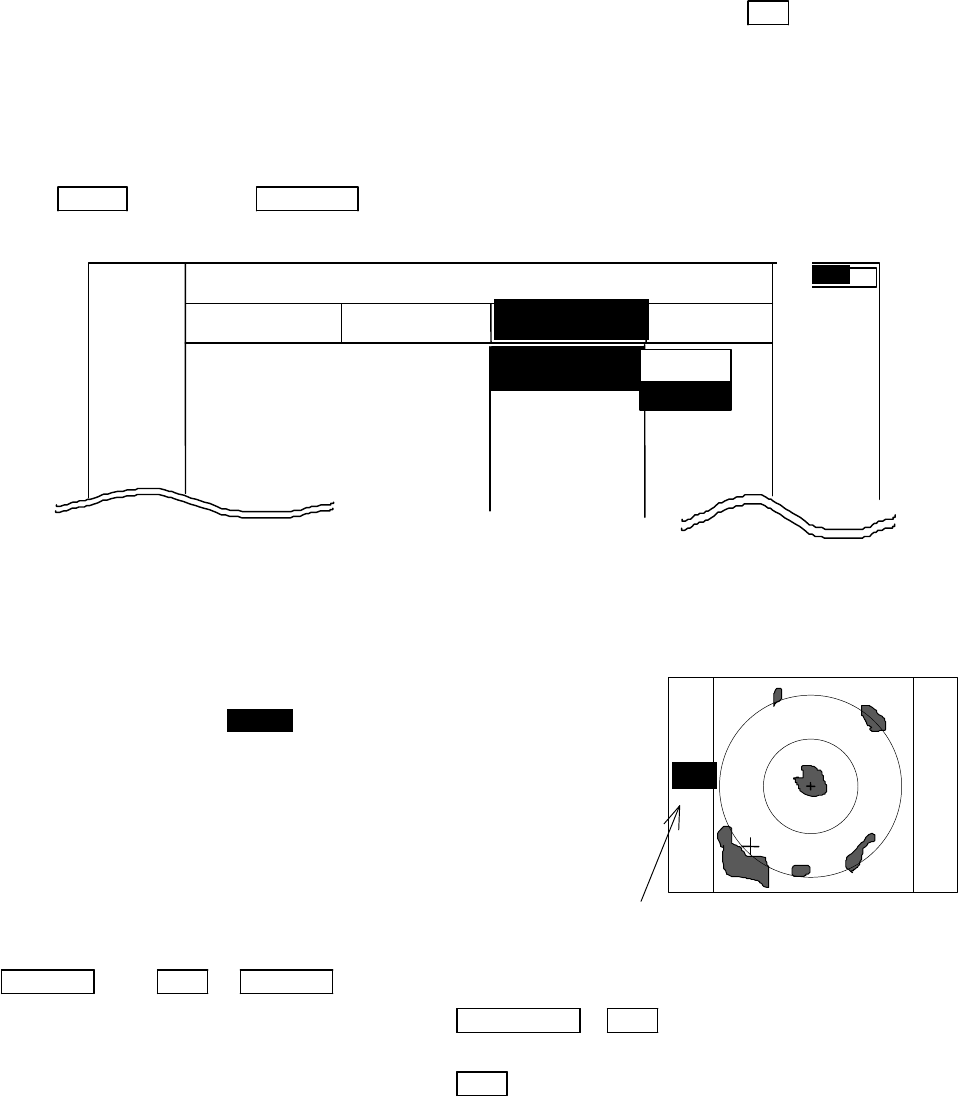
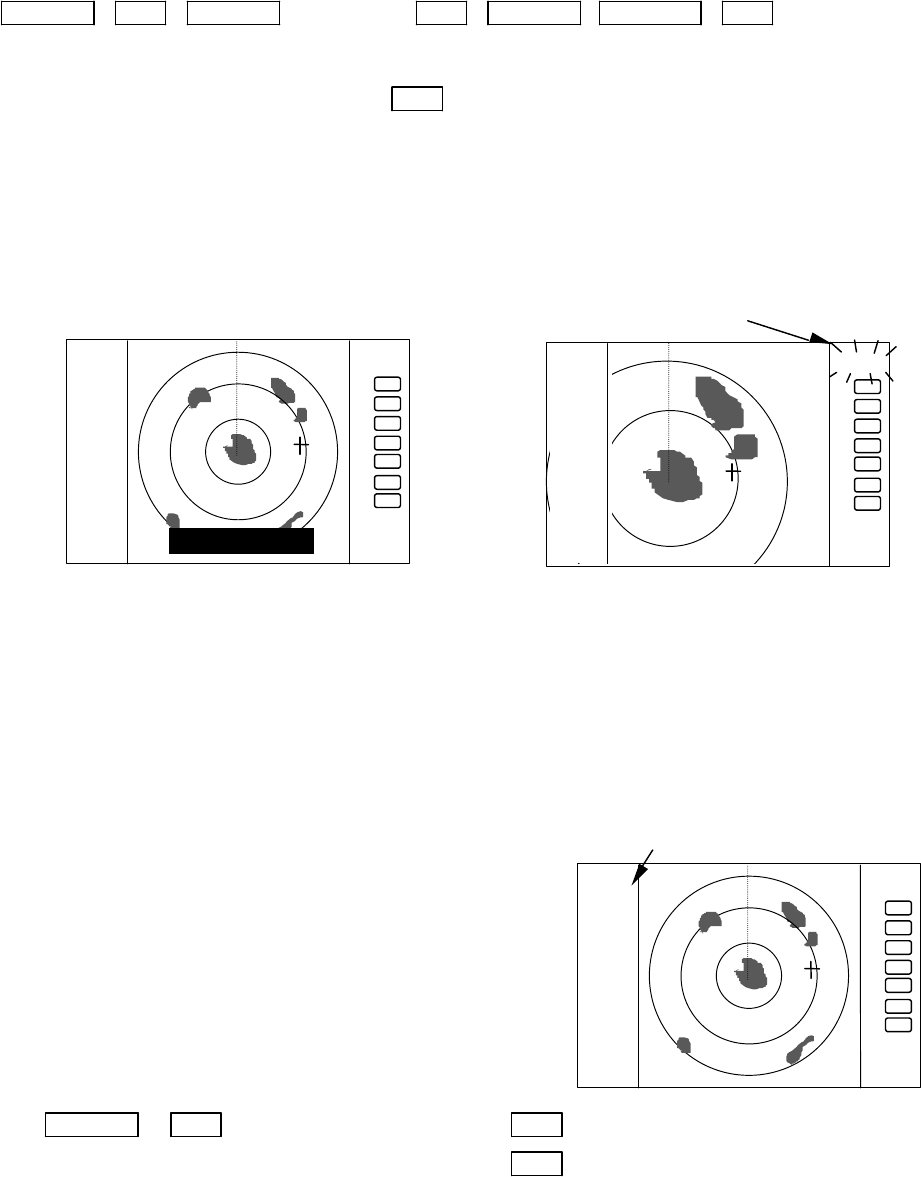
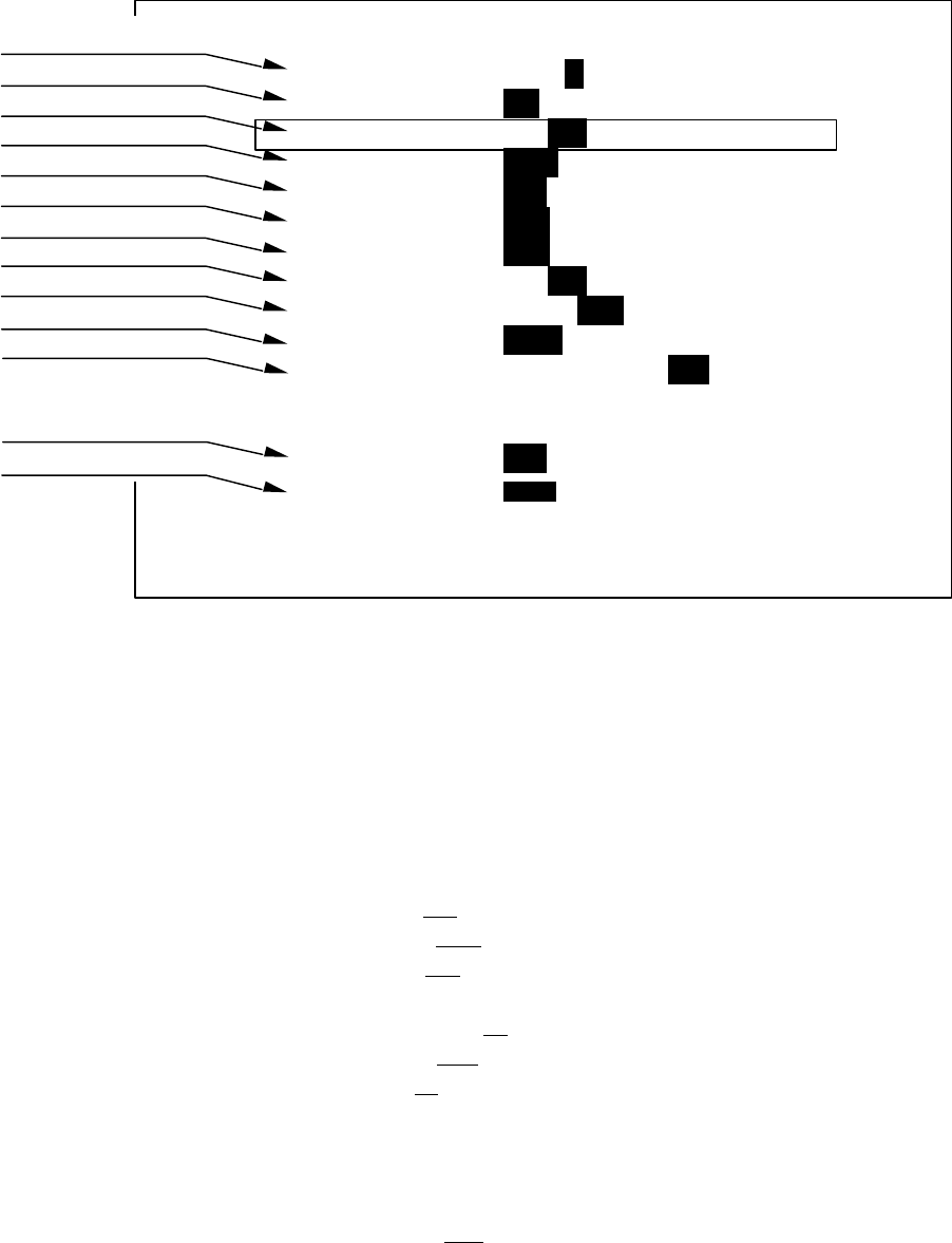
5.5.2.2 Setting the Guard Zone (GZ)
The following procedure sets up the distance, depth and the width of the guard zone. Once set, the guard
zone detects the existence of echoes exceeding a prefixed level and then generates an audio alarm (IN
MODE) or, it detects non-existence of echoes that has left the guard zone (OUT MODE).
(1) Select GZ from the pull-down menu using the up-down cursor keys, and press the “ENT” key.
The ON/OFF sign is displayed beside the letters GZ.
Up/Down → ENT ON/OFF sign is displayed.
(2) Select “ON” by “common operation for the GZ menu”,
and press the “ENT” key. GZ IN
SET CENTER POINT
MARK
MODE >
GZ >
OFF-C >
SLEEP >
.75
.25
HU L NAV ECHO SETUP
NAVIGATION
>>>
0.23 NM
AT
HU
HS
NU
CU
TM
54
(3) The GZ IN sign appears in the left side of the screen,
showing the present mode setting. A small cross cursor
appears on the screen center for setting up the guard
zone. A prompt "SET CENTER POINT appears at the
bottom, requesting to define the center of the guard zone.
(4) Move the cross cursor to the center of the warning zone to be set, using the up-down and left-right
cursor keys, and then press the "ENT" key. The guard zone appears now.
(5) From the cross cursor position as set in step (4), expand the guard zone as follows.
(6) After setting the guard zone, fix it by pressing the "ENT" key.
To cancel the guard zone function, select “OFF” by
“common operation for the GZ menu”, and press the
“ENT” key.
ENT
→Up/Down &Left/Right →ENT → Up/Down &Left/Right →ENT -------------------------------- Setting completed
(Setting the center of GZ) (Setting the scope of GZ)
Stop the alarm tone
To momentarily silence the audio alarm, press any key on the control panel. In this state, the guard
zone function is still operative. To permanently turn off the guard zone function, select "OFF" from
the GZ menu.
Note1: To switch the IN or OUT mode, refer to “Guard Zone Mode” in section 5.5.4.5.3 “Changing the
content of settings 2 (PRESET2)”
Note2: To set the guard zone level, refer to “Guard Zone LeveL” in section 5.5.4.5.3 “Changing the content
of settings 2 (PRESET2)”
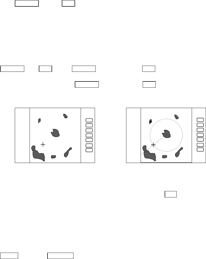
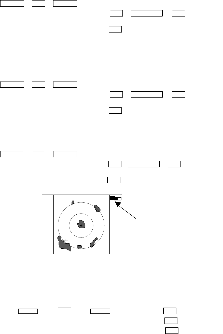
5.5.2.3 Shifting display in specific direction (OFF-C)
Displaying the location specified by the cross cursor as the vessel's location.
(1) Select OFF-C from the pull-down display items using up-down cursor key, and press the "ENT" key.
(2) When the ON/OFF sign is displayed beside the OFF-C item, select ON with the up-down cursor keys
and press the "ENT" key.
(3) OFF-C is displayed in the upper right corner of the screen and "SET OFF CENTER POINT" at the
bottom of the screen, and setting is ready to be entered. Move the cross cursor with the cursor keys
to move own ship’s position to an intended location, and press the "ENT" key. Own ship’s position
will be moved to cursor's location. The reversed OFF-C sign will be put back to normal display,
indicating the off-centered screen is now set up.
(4) To cancel “OFF-C” function, either select OFF in (2)
Use the right cursor key to enlarge the guard
zone width and left cursor key to contract the
width using the left cursor. The guard zone
expands and contracts with respect to the cross
cursor position.
The mode (IN or OUT) is displayed when the state is ON. Nothing
is displayed when it is OFF.
GZ IN
55
Up/Down → ENT → Up/Down
(Select OFF-C) |→(Select ON) ENT →Left/Right &Up/Down →ENT------- Set OFF-C
→(Select OFF) ENT ------------------------------------- Cancel OFF-C
Note: The VRM2 and EBL2 do not follow the OFF-C function while they are floated.
The function operates only on PPI screen.
5.5.2.4 Setting of the SLEEP function(SLEEP)
This function allows a 30-second-transmission during pre-fixed times. Following the transmission cy-
cle, a power-saving mode will be activated with the screen display put into ST'BY state (the scanner-OFF
state) and the LCD backlighting turns off, accordingly. This action is repeatedly executed.
For practicing purpose, set a guard zone and have the warning signal automatically activated every prefixed
period.
(1) Use the up-down cursor keys to select SLEEP from the pull-down menu, and press the "ENT" key.
(2) When the OFF/5min/10min/15min display appears beside the SLEEP item, select a time to be set with
the up-down cursor keys.
(3) Press the "ENT" key to complete the setting. To cancel the SLEEP function, select OFF in step (2).
After setting a SLEEP mode, a transmission takes place and 30 seconds later the ST'BY state is estab-
lished, turning the backlight off. (Power-saving mode). Two minutes before the prefixed time the backlight
turns on again and the 2-minute timer starts. Then, at the fixed time another 30-second-transmission starts.
This series of actions are repeated. If you press any key during the course of this action, the SLEEP function
will be canceled.
(a) Setting procedure
Up/Down → ENT → Up/Down →(Select OFF) → ENT ------------------------------ SLEEP function is turned OFF
(Select SLEEP) →(Select 5min.) → ENT → POWER ------- 30-second-transmission every 5 min.
→(Select 10min.) → ENT → POWER ------30-second-transmission every 10 min.
→(Select 15min.) → ENT → POWER ----- 30-second-transmission every 15 min.
Transmission
Setting completed
(b) Action after setting
SLEEP setting ( 5min. ) (Operation)
|
^ (Under Tx) ^ (Under power-saving mode) ^ (2min. timer in use) ^ (Under Tx) ^ (Under power-saving mode)
0 sec. 30 sec. 3 min. 5min. 5and a half min. (Time used)
TX Start TX OFF Backlight ON Tx Start TxOFF (Action)
Countdown start
.
75
.25
HU
.
75
.25
HU
SET OFF-C POINT
OFF-C
Move the cross cursor indicates "OFF-C" state is entered
56
-- What happens if a key is pressed after a SLEEP mode setting?
If a transmission has started and you press a key after setting a SLEEP mode, power-saving mode will
be activated 30 seconds after a key is pressed.
-- What happens if a key is pressed during the SLEEP mode?
a) If you press a key during the power-saving mode, the SLEEP function will be canceled and
the 2-minute timer starts.
b) If you press a key while the 2-minute timer is in active, or during transmission, the SLEEP
function will be canceled.
5.5.3 Echo Menu xxx = Keys to press
This pull-down menu provides various pre-settings for the radar PPI video shown on the screen.
<Common operations for the ECHO menu >
Press the "MENU" key and select "ECHO" from the displayed 4 main menus using the left-right cursor.
All items of the ECHO menu will be shown in a pull-down form as shown below.
MENU → Left/Right
(Select ECHO)
5.5.3.1 Sensibility adjustment (GAIN)
(1) Use the up-down cursor keys to select GAIN from the pull-down display items, and press either the
"ENT" key or the right cursor key.
(2) Select MENU from the MANU/AUTO display beside the GAIN item using the up-down cursor keys,
and press the "ENT" key.
(3) The present state of GAIN is displayed in reverse form on the
left side of the screen as G 35 , showing the gain setting is
ready for entry.
(4) Turn the rotary control, observing the screen. The figure shown
on the screen changes within a range of 0 and 99.
(5) The GAIN adjustment completes by pressing the "ENT" key
after the setting.
When you wish to enter the AUTO function, select AUTO
in step (2) and press the "ENT”.
Up/Down → ENT → Up/Down
(Select GAIN) |→(Select MANU) →Control knob → ENT ------------Set to MANU mode
| (GAIN adjustment)
|→(Select AUTO) →ENT ----------------------------------- Set to AUTO mode
The setting value is displayed during MANUAL op-
eration. AT is displayed during AUTO operation.
(The same applies to STC, FTC and TUNE.)
G 35
56
MARK
.7 5
.2 5
HU L NAV ECHO SETUP
ECHO
>>>
0.23 NM
GAIN >
STC >
FTC >
TUNE >
ST >
MANU
AUTO
AT
57
5.5.3.2 Removing sea clutter (STC)
Refer to the section, “Sensibility adjustment (GAIN)”.
Up/Down → ENT → Up/Down
(Select STC) |->(Select MANU) → ENT → Control knob → ENT -Set to MANU mode
| (STC adjustment)
|->(Select AUTO) → ENT ------------------------------------Set to AUTO mode
Note: When you select the MANU mode, the GAIN and FTC functions will be switched to MANU mode,
too.
Note: When you select the HARBOR mode, FTC will be switched to MANU mode.
5.5.3.3 Removing rain and snow clutter (FTC)
Refer to the section, “Sensibility adjustment (GAIN)”.
Up/Down → ENT → Up/Down
(Select FTC) |->(Select MANU) → ENT → Control knob → ENT -- Set to MANU mode
| (FTC adjustment)
|->(Select AUTO) → ENT ------------------------------------Set to AUTO mode
5.5.3.4 Adjusting the receiver tuning (TUNE)
Refer to the section, “Sensibility adjustment (GAIN)”.
Use the following key operations to set up the tuning.
Up/Down → ENT → Up/Down
(Select TUNE) |->(Select MANU) → ENT → Control knob → ENT ---- Set to MANU mode
| (TUNE adjustment)
|->(Select AUTO) → ENT ------------------------------------Set to AUTO mode
5.5.3.5 Echo expansion (ST)
This function stretches the echo towards range, for easy recognition of the target on the screen.
Two types of the echo expansion is available. Select ST1 or ST2 from the menu.
(1) Use the up-down cursor keys to select ST from the pull-down display items, and press the "ENT" key.
(2) Select ST1 or ST2 from the display beside the ST item using the up-down cursor keys, and press the
"ENT" key.
Up/Down → ENT → Up/Down → (select ST1) → ENT set ST1
|→ (select ST2) → ENT set ST2
|→ (select OFF) → ENT ST OFF
35
Indicated setting value on manual
mode,
AT on auto mode
58
( expansion rate ST1<ST2 )
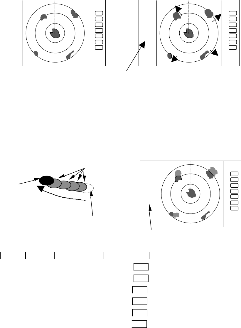
5.5.3.6 Displaying the target track (TRACK)
(1) Use the up-down cursor keys to select TRACK from the pull-down display items, and press the "ENT"
key.
(2) Select 15SEC, 30SEC, 1MIN, 3MIN, 6MIN, or CONT from the display beside the TRACK item using
the up-down cursor keys, and press the "ENT" key.
(3) If you select 15SEC, the sign "TRK 15S" appears on the left side of the screen, entering the assigned
track interval. The “TRK 15S” indicates the length of the track, displaying a 15-second-long sailing
track at maximum.
Note: When PPI+PPI or ALL PPI+PPI screen mode is used, TRACK function can be used
only on CONT mode.
The key sequence for setting up the ship’s track
up/down → ENT → up/down →(select OFF)→ENT TRACK OFF
|→(select 15SEC)→ENT set 15sec. track
|→(select 30SEC)→ENT set 30sec. track
|→(select 1MIN) →ENT set 1 min. track
|→(select 3MIN) →ENT set 3 min. track
|→(select 6MIN) →ENT set 6 min. track
|→(select CONT)→ENT set continue track
5.5.3.7 Enlarging the selected areas (ZOOM)
Using this function, you can enlarge the selected zone around the cross cursor twice as large as the one
displayed on the screen.
(1) Use the up-down cursor keys to select ZOOM from among the pull-down display items, and press the
"ENT" key.
(2) Select the ON using up-down cursor keys from the ON/OFF display beside the ZOOM item, and press
the "ENT" key.
.75
.25
HU
+
ST1
.75
.25
HU
+
The picture to display echoes
expanded in the direction of
the distance
ST1, or ST2 display,
no display on OFF state
ST function is OFF
disappears after selected time
Present
echo
Tracks of target
moving direction
the length of the track
.75
.25
HU
+
TK 15SEC
59
(3) A small cross cursor and the prompt "SET ZOOM POINT" will be displayed on the screen center and at
the bottom respectively.
(4) Use the cursor keys to move the cross cursor to the point to be magnified, and press the "ENT" key to
complete the setting. The area around the cross cursor is displayed in 2x magnification, with blinking
"ZOOM" displayed in the upper right corner of the screen, indicating that a ZOOM display is shown.
(5) To cancel the ZOOM function, select OFF in step (1) or begin operation of range.
Up/Down →ENT →Up/Down (Select ON) →ENT →Up/Down &Left/Right →ENT ZOOM
Setting
(Select ZOOM) | (Move cross cursor)
|→ (Select OFF) →ENT ---------------------------------------ZOOM canceled
Note 1) VRM2 and EBL2 do not follow the ZOOM function during they are floated.
Note 2) Normal screen returns when you change the range scale.
Note 3) ZOOM function is usable only in PPI screen mode.
Note 4) ZOOM function is unusable in OFF-C.
Note 5) The ZOOM center can be set any desired position within the set range.
5.5.3.8 Increasing the sensitivity (S/L)
The pulse length is automatically changed as you change the range scale. However, if you wish to in-
crease the sensitivity or to improve the picture definition, change the pulse length according to your need. If
you select the short pulse (SHORT), the picture will become more definite, giving higher range discrimina-
tion. If you select the long pulse (LONG), the picture will be stretched towards range, providing better rec-
ognition of the targets shown, in contrast, the range discrimination will be sacrificed.
(1) Use the up-down cursor keys to select S/L from among the pull-down display items, and press the "ENT"
key.
(2) Select Pulse length (SHORT or LONG) using the up-down
cursor keys from the SHORT/LONG display beside the
S/L item.
(3) The setting will be completed when the “ENT” key is
pressed after the selection.
Up/Down → ENT →(Select SHORT) → ENT ------------------------- Set to short pulse
|→(Select LONG) → ENT -------------------------- Set to long pulse
.75
.25
HU S
+
S or L display
.75
.25
HU
SET ZOOM POINT
.75
.25
HU ZOOM
blinking "ZOOM"
60
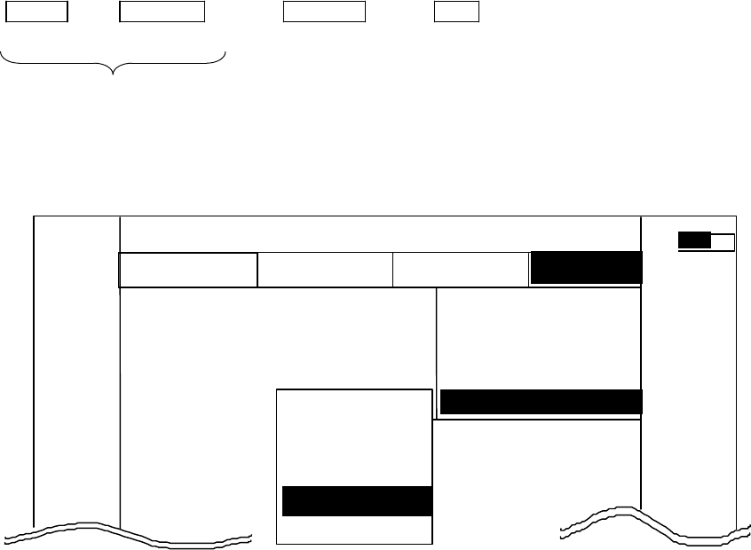
5.5.4 SETUP Menu
Using this menu, you can select and set up the following picture presentation modes:
(1) PPI: A basic presentation mode composed of a complete PPI screen, with
status displays on the left side, and an array of the soft keys on the right
side of the screen.
(2) SEMI3D/PPI: A small complete PPI on the left side and a semi-3D screen on the right
side.
(3) PPI/PPI: Two small complete PPI screens on both sides, with the status display
and the soft keys at the bottom and in the right side, respectively.
(4) PPI/NAV: A small PPI screen on the left side and the NAV information on the right
side. The status display and an array of the soft keys are positioned at
the bottom and in the right side of the screen, respectively.
(5) ALL PPI: A single, largest PPI screen is shown. The top and the bottom parts of
the PPI screen are truncated, while the right and left sides of PPI are
fully displayed.
(6) ALL PPI/PPI: Two larger PPI screens with truncated bottom.
(7) MOB: A Nav display, showing the position of MOB (Man Over Board) and
present ship’s position in latitude and longitude coordinate.
<Common operations for the SETUP menu>
(Up to the point when "SETUP" menu is selected from the main menu)
Press the "MENU" key and select "SETUP" from the displayed 4 main menus using the left-right
cursor. (The contents of the selected MENU will appear on a pull-down display in accordance with the
movement of the left-right cursor.)
MENU → Left/Right
(Select SETUP)
Further explanation about the SETUP menu will be conducted on the assumption that this "common
operation for the SETUP menu" has already been completed.
5.5.4.1 Selecting and setting up the screen mode (WINDOW)
(1) Use the up-down cursor keys to select WINDOW from among the pull-down display items, and press the
"ENT" key.
(2) Select a screen to be displayed with the up-down cursor keys from among the above 7 items shown beside
the WINDOW item.
(3) The setting will be completed when you press the "ENT" key after the selection.
MARK
WINDOW >
SEL WIN >
PICTURE >
SYSTEM CHECK
CUSTOM >
. 75
.25
HU NAV ECHO SETUP
SEMI3D / PPI
PPI / PPI
PPI / NAV
ALL PPI
ALL PPI/PPI
MOB
PPI
SETUP
>>>
0.23NM
AT
61
Up/Down → ENT → Up/Down → (Select PPI) → ENT (a)
(select WINDOW) → (Select PPI+SEMI3D) → ENT (b)
→ (Select PPI+PPI) → ENT (c)
→ (Select PPI+NAV) → ENT (d)
→ (Select ALL PPI) → ENT (e)
→ (Select ALL PPI+PPI) → ENT (f)
→ (Select MOB) → ENT (g)
-Available functions on each screen mode
SCREEN
ITEM
PPI PPI/SEMI3D
PPI/NAV
PPI+PPI ALL PPI ALL PPI PPI
MOB
RANGE ¡ ¡ ¥ ¡ ¥ X
VRM1, EBL1 ¡ ¡ o X X X
VRM2, EBL2 ¡ ¡ o X X X
FL VRM2/EBL2 ¡ X X X X X
RINGS ON/OFF ¡ ¡ ¡ ¡ ¡ X
ZOOM, OFF CENT
¡ X X X X X
///CSR ¡ ¡ o ¡ ¡ X
HDG OFF ¡ ¡ ¡ X ¡ X
STERN M ¡ ¡ ¡ ¡ ¡ X
NORTH M ¡ ¡ ¡ ¡ ¡ X
GAIN, STC, FTC ¡ ¡ ¥ X X X
TUNE ¡ ¡ ¡ X X X
ST ¡ ¡ ¡ X X X
GZ ¡ ¡ ¥ X X X
SEL WIN X X ¡ X ¡ X
TXON/OFF ¡ ¡ ¡ ¡ ¡ X
¥ : The control available on active screen only. To use the function on another
screen, switch the active screen using the SEL WIN function.
¡ : Simultaneous control is possible for dual screen.
o : The function is available only on PPI screen.
X : The function not available.
- Screen modes and Operations
(a) PPI Screen
All functions can be used on this screen.
(b) PPI/SEMI3D Screen
.75
.25
HU
+
PPI Screen
62
All controls, such as EBLs, VRMs are active on both screen.
The functions such as ZOOM, OFF-C, FL EBL2, and FL VRM2 are not
availabel in this mode. In the "SEMI3D" screen, ship's heading
direction always stays on the center vertical line denoted 000.
(c) PPI/PPI Screen
Each radar screen is updated one then the another on every two antenna scans, as shown in the
following illustration. The unupdated picture remains frozen while another screen is in process.
Note: When your ship navigates at high speed, use a single PPI screen mode to obtain faster picture
update.
Note: Functions including ZOOM, OFF-C, FL-EBL2, and FL-VRM2 are not available in this screen mode.
Note: The functions including RANGE, GAIN, STC, FTC, and GZ can be used independently for each
screen. The screen with reversed range display, as selected in "SEL WIN", is an active display, in
which you can operate available functions.
Note: The cross cursor will be displayed only on a selected screen.
-Operation
a) Changing the RANGE scale in LEFT screen
1) When the RIGHT range scale indicator is reversed, use the "SEL WIN" function to make the
LEFT screen to be active.
2) Press the ”RANGE UP” or ”RANGE DOWN” key to change the RANGE scale.
.75 .25 HU
+
280 320 000 040 080
PPI/SEMI3D Screen
.75
.
25
HU S
24
6
+
G 55/35
S 35/AT
F 35/AT
LEFT screen selected
.75
.
25
HU S
24
6
+
G 55/35
S 35/AT
F
35/AT
LEFT GAIN is ac
tive
Left GAIN in reverse
LEFT screen /--------/*******/--------/******/--------/****** t→
RIGHT screen *******/--------/******/--------/******/--------/
picture drawing(refreshed)
displayed previous picture ( held)
63
b) Adjusting GAIN of LEFT screen.
1) When the RIGHT range indicator is displayed reverse, use the "SEL WIN" function to make the
LEFT screen to be active.
2) Press the "GAIN" key and the letters "G50" will be displayed in reverse, indicating the GAIN
adjustment is available.
3) Adjust GAIN with the rotary control.
Adjust STC and FTC in the same manner as GAIN.
Note: While the adjustment of GAIN, STC, or FTC is in process, the radar picture update will be
frozen. In approximately 5 seconds after the adjustment, the radar picture update will be
resumed.
c) Using VRM1 on LEFT screen.
1) When the RIGHT range indicator is displayed in reverse,
change the active screen to LEFT screen with "SEL
WIN" function.
2) Press the "VRM1" key and " " will be displayed in
reverse, indicating the VRM1 is available.
3) Rotate the rotary control to measure the distance.
4) The same procedure applies to VRM2, EBL1, or EBL2.
NOTE: To use the VRM1 on the RIGHT side screen, first
switch the active display to RIGHT side, then press the
VRM1 key.
(d) PPI/NAV Screen
Note: The ZOOM, OFF-C, FL EBL2, and FL VRM2 are
not available in this screen mode.
(e) ALL PPI Screen
Note1: The status display such as RANGE, RINGS interval, and
Display mode are displayed in the upper-left corner of
the screen.
Note2: When you press any key except "MENU", "RANGE
UP/DOWN", "BRILL", and "POWER", the screen will
return to the PPI mode.
1 0.00NM
G 55/35
S 35/AT
F 35/AT
1 0.00NM
Determining the distance with VRM1
on LEFT screen
.75
.25 HU S
6
1
+
+
NAV DISPLAY
WAY P 123.4°
6.8NM
COURSE 2.38NM
XTE <<<
HDG 267.3°T
SPD 12.8KT
TEMP 20.8°C
DEPTH 58.3M
LAT/LON
34°08. 22N
138°02. 53E
PPI/NAV screen
.75
.25 HU S
+
. 75
. 25
HU S
ALL PPI screen
64
(f) ALL PPI/PPI Screen
Note1: The RANGE, RINGS interval, and Display mode are shown on
top of the screen.
Note2: When you press any key except "MENU", "RANGE
UP/DOWN", "BRILL", and "POWER", the screen will return
to PPI/PPI mode.
Note3: Each radar picture is updated every two antenna scans. The
right screen picture is frozen while the left screen is updated, and
vice versa. When your ship navigates at high speed, use a single
PPI screen to obtain faster picture update.
(g) MOB Screen
The MOB key has been pressed, the MOB position and ship's
position are displayed. If not, MOB position will be displayed with
bars( --.- )
Press MOB key to clear the MOB position and return to previous
screen. Press ENT key to return previous screen with keeping the MOB
position data.
5.5.4.2 Switching screens on PPI/PPI screen ( SEL WIN )
Switching to the desired screen for activation on a PPI/PPI screen display.
The "SEL WIN" function switches the activated screen to effect the operation such as, RANGE, GAIN,
STC, FTC, VRM1/2, EBL1/2, and guard zone. The range indicator of activated screen is displayed in reverse.
When "SEL WIN" is selected with the up-down cursor keys from among the pull- down display items
and the "ENT" key is pressed, activated screen will be changed to the opposite screen.
Up/Down → ENT the opposite screen activated
(select SEL WIN)
+
ALL PPI PPI screen
.75
.25 HU S
6
1
MAN OVERBOARD
MOB POS
37°08. 42N
142°03. 33E
SHIP’S POS
37°12. 42N
142°04. 33E
PRESS MOB KEY TO DATA CLEAR
PRESS ENTER KEY TO RETURN
Range display on the active screen become a reverse display
.75 .25 S .5 .25 .75 .25 HU S .5 .25 .
65
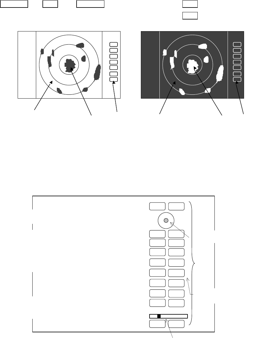
5.5.4.3 Changing the color of screen (PICTURE)
Changing the color of screen depending on weather and day / night environment conditions will be
effective for easy viewing .
When "PICTURE" is selected with the up-down cursor keys from among the pull- down display items,
select "DAY" and press "ENT" key to set to day display. Night display appears if "NIGHT"
is selected
Up/Down → ENT → Up/Down → (select DAY) → ENT → day display
(select PICTURE) → (select NIGHT)→ ENT → night display
Blue Yellow White Black Green Red
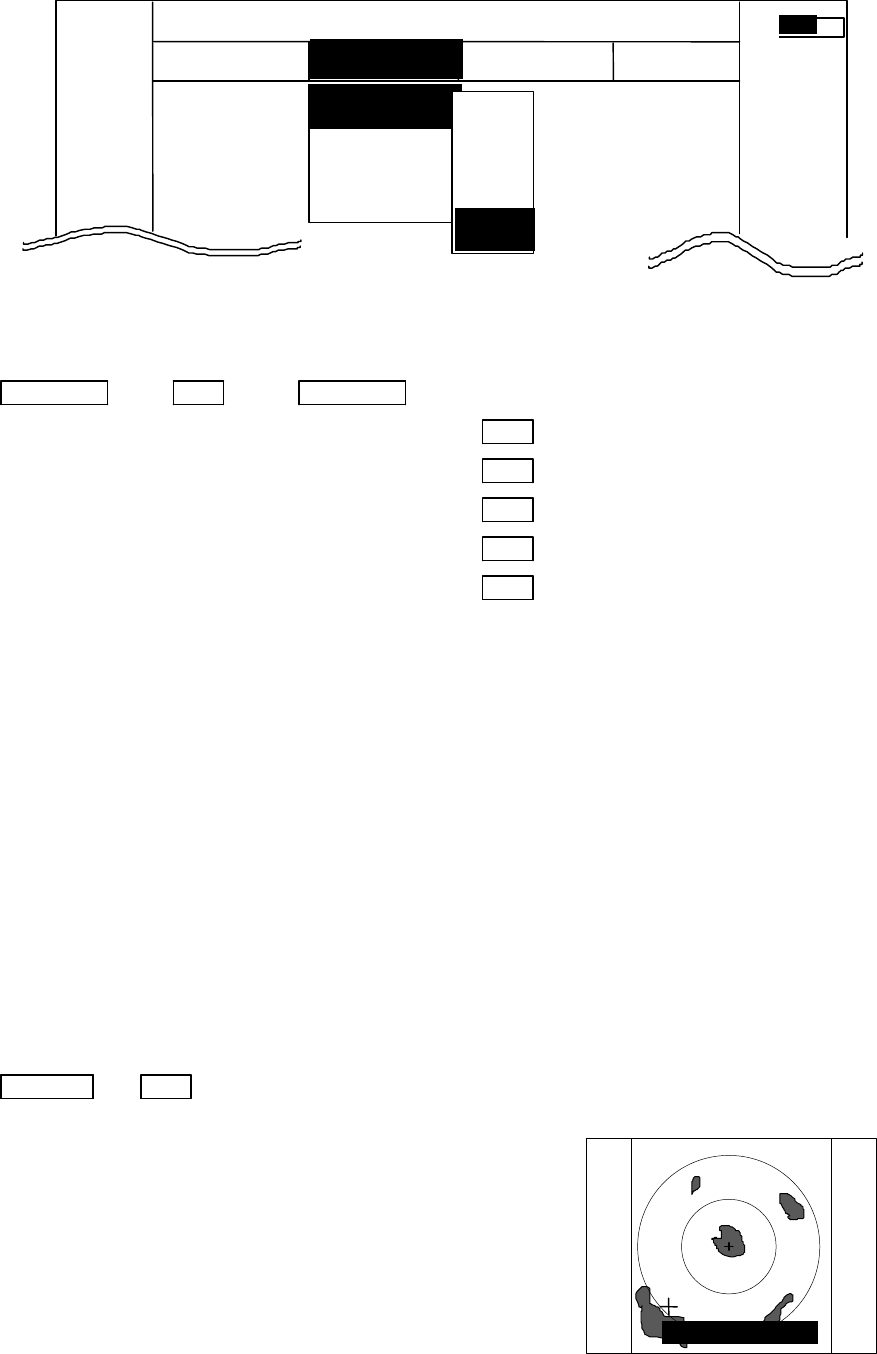
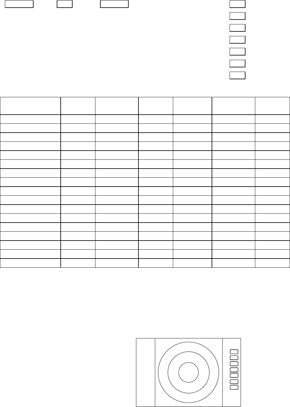
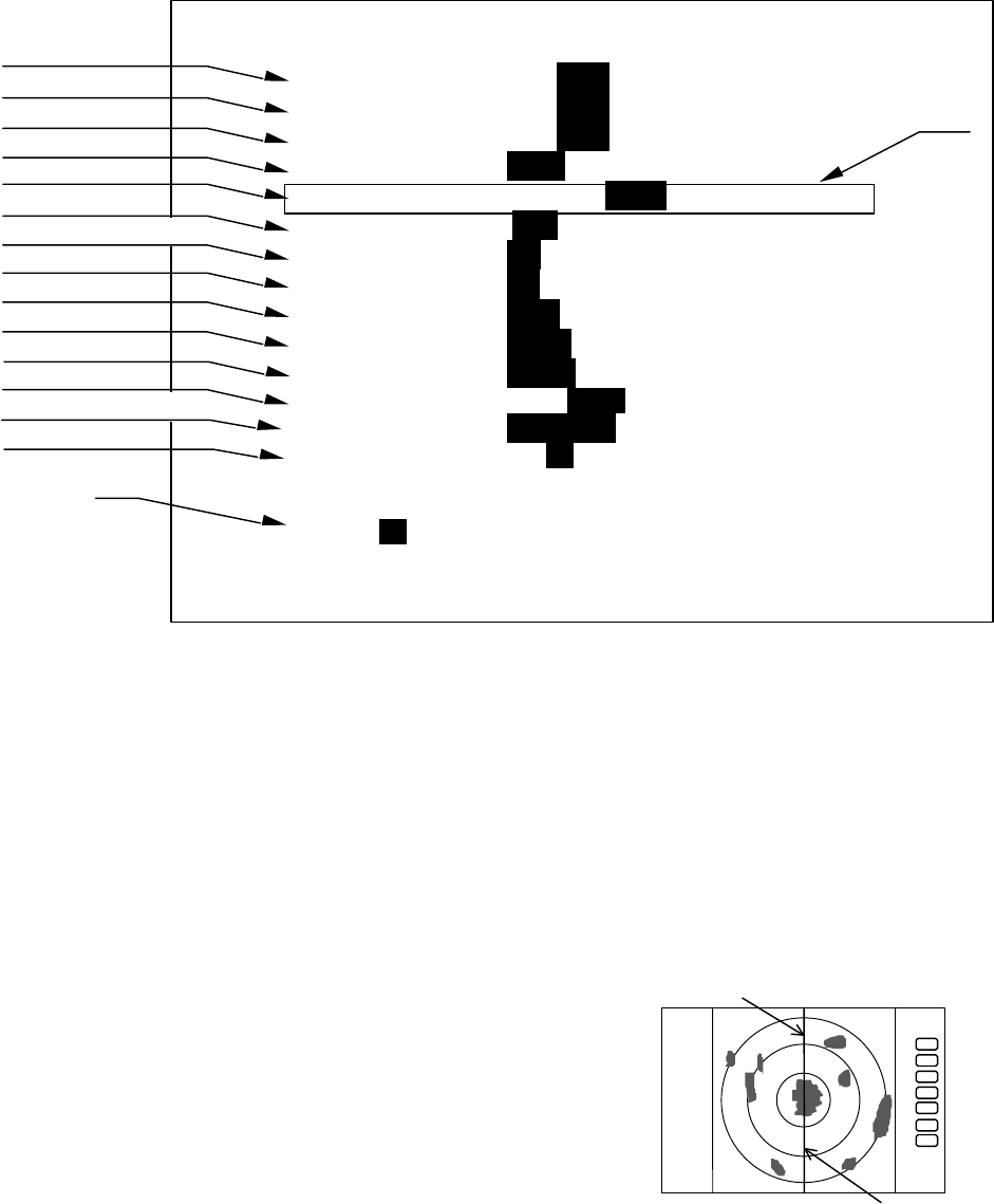
5.5.4.4 Fault Diagnosis by Self Check (SYSTEM CHECK)
Verifying the problem point by SYSTEM CHECK when, for example, some abnormality has occurred.
(1) Select SYSTEM CHECK from the pull-down display items using up-down cursor key, and press the
“ENT” key.
(2) The system check screen will appear.
DAY display NIGHT display
75
. 25
HU
. 75
. 25
HU
RNG U
RNG D
BRILL
AUTO
GAIN
STC
F
TC
1
2
3
4
5
6
7
MOB
POWER
SYSTEM CHECK screen
ENT
MENU
Indicates the control knob status.
Indicates the cursor status.
CONTROL KNOB
SYSTEM CHECK
MEMORY CHECK
a) ROM --------------------------------------- > ROM OK
b) RAM---------------------------------------- > RAM OK
c) Backup memory----------------------- > BACKUP OK
SIGNAL CHECK
d) Transmit trigger ----------------------- > (1) TRIGGER OK
e) Bearing pulse -------------------------- > (2) AZIMUTH OK
f) Heading pulse -------------------------- > (3) HM OK
g) +5Vvoltage(at video circuit) ----- > (4) +5V OK 5.2V
h) High voltage(at scanner) ---------- > (5) H.T. AT SU OK 253.2V
i) High voltage(at display)------------- > (6) H.T. AT DU OK 253.2V
j) Magnetron current
--------------------- > (7) MAG. CUR. OK 2.1
k) Tuning voltage------------------------- > (8) TUNE OK
l) Motor power (6 kW/12 kW only)----- > (9) MOTOR OK 40.0 V
m) Cumulative usage time --------> HOURMETER
Operation time --------------------- > OPERATE 12.0H
Transmit time ---------------------- > TRANSMIT 10.3H
n) ROM version ------------------------> ROM VERSION V1.00
o) Scanner type ------------------------> 4 KW OPEN
PRESS POWER KEY TO RETURN
p) Indicates the operation
status of front-panel keys.
ACQ
TGT N
66
While watching the screen , check the following:
i) Whether all items are marked “OK”. (If any item is marked “NG”, the indicated location may be
faulty.)
ii) Press a front-panel key and see if the corresponding display on the screen is highlighted.
iii) Turn the control knob and see if the lower-right indicator move to right or left.
(3) Press the POWER key to return to the previous screen
a) ROM Indicates the ROM status.
b) RAM Indicates the RAM status.
c) Backup memory Indicates the backup memory status.
d) Transmit trigger Indicates the signal line status for the trigger signal sent from the scanner
unit.
e) Bearing pulse Indicates the signal line status for the bearing signal sent fron the scanner
unit.
f) Heading pulse Indicates the signal line status for the bow signal sent from the scanner unit.
g) +5V voltage Indicates the reference voltage status of the video circuit and its voltage
value.
(at video circuit) (normally about 5 V)
h) High voltage(at SU) Indicates the status of the high voltage supplied from the display unit to the
scanner unit and its voltage value (normally about 250 V) at scanner unit.
i) High voltage(at DU) Indicates the status of the high voltage supplied from the display unit to the
scanner unit and its voltag value (normally about 250 V) at display unit.
j) Magnetron current Indicates the status of the anode current flowing in the magnetron and its
current value.
k) Tuning voltage Indicates the status of the voltage used for tunning and its voltage value.
l) Motor Indicates the status of the scanner motor power (normally about 40 V)
m) Cumulative usage time Indicates the cumulative time your radar is used.
OPERATE : Duration of time during which the power supply is turned on.
TRANSMIT : Duration of time transmitting.
n) ROM version Indicates the ROM software version.
o) Scanner type Indicates the Scanner type ex. 4 KW OPEN
p) Front-panel keys As you press any front-panel key when the SYSTEM CHECK screen is on,
the corresponding key is highlighted on the screen by displaying it in reverse
video.
67
5.5.4.5 Changing the content of the setting (CUSTOM)
Note) The items included in the CUSTOM menu are the settings and adjustments to be carried out during
installation. These items are not required during normal operations.
-Common operations for CUSTOM
Use the up-down cursor keys to select CUSTOM after ”the common operations for the SETUP” menu,
and press the "ENT" key.
MENU → Left/Right → Up/Down → ENT
(Select SETUP) (Select CUSTOM)
Common operation for SETUP
When the above operations are completed, the following 4 items will be displayed beside the CUSTOM
item, namely "KEY ASSIGN", "PRESET1", "PRESET2" and "ADJUST".
Further explanation concerning the CUSTOM menu items will be made assuming that the above "common
operations for CUSTOM" have already been conducted.
CUSTOM
>
MARK
WINDOW >
SEL WIN >
PICTURE >
SYSTEM CHECK
CUSTOM >
.75
.25
HU S NAV ECHO SETUP
SETUP
>>>
0.23NM
AT
KEY ASSIGN
PRESET1
PRESET2
NMEA PRESET
ATA PRESET
ADJUST >
ADJUST >
68
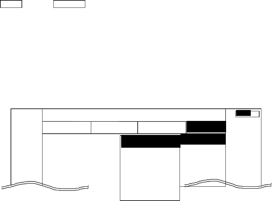
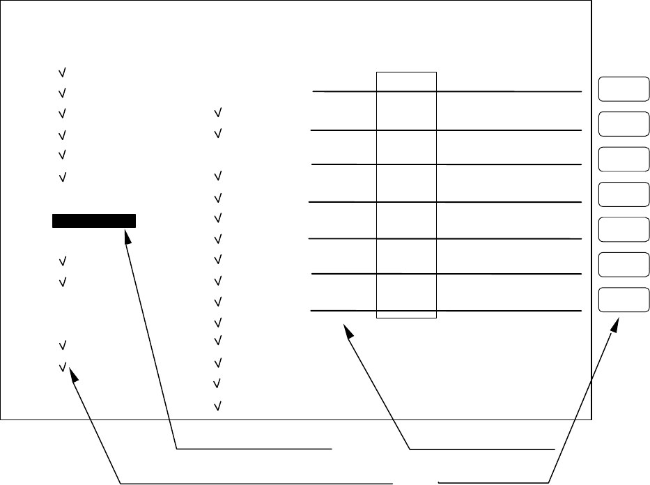
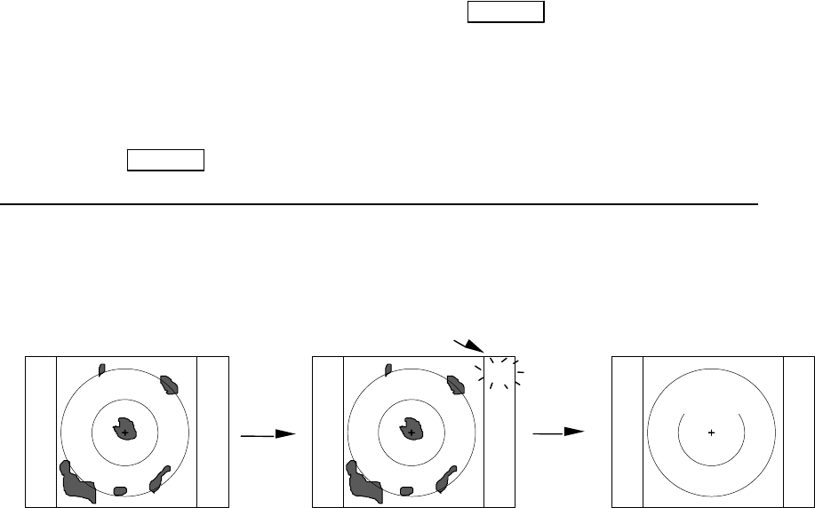
5.5.4.5.1 Changing the settings of the soft keys (KEY ASSIGN)
To change the function settings that have been assigned to soft keys, numbered 1 to 7, use the fol-
lowing procedures.
(1) Screen display for the setting
Select KEY ASSIGN from the CUSTOM items and press the "ENT" key. The following screen will be
shown. (See chart below)
(2) Selecting functions
Reverse the items to be set using the up-down cursor keys. (The items become reverse in accordance with
the moving cursor.)
(3) Key settings
(3)-1 Allocating a new function to a soft key (Example 1)
Upon reversing the item with up or down key, press the key to be allocated. The selected item will
be displayed beside the key, which indicates that the setting has been completed.
(3)-2 Changing the function of a key with an preset function (Example 2)
When the allocated key is pressed, its function will be altered to the one selected in (1) above and the
previous function will be canceled.
The current setting item numbers as SET1-4 are always displayed below the letters NEXT. In order
to switch the settings SET1-4, use the right-left cursor keys.
NOTE: Double settings, setting 1 item for more than 1 key, are possible.
When you wish to assign the functions for more than 1 key, repeat the operations (3)-1 to (3)-2.
(Example 3)
1
5
6
7
4
3
2
KEY ASSIGNMENT
EBL1 EBL2 DATA PPI
VRM1 VRM2 DEL PPI/3D
VAR RNG FL EBL2 ALL DEL PPI/PPI
TRACK FL VRM2 TRACK PPI/NAV
TARGET GZ ZOOM ALL PPI
SEL WIN OFF-C PICTURE ALL PPI2
NEXT NEXT NEXT NEXT
SET1 SET2 SET3 SET4
Key Groups
Move with up-down cursor Move with right-left cursor
Mark is displayed when the function is set to a key. Operation panel Keys 1 - 7
Soft Key Setting Screen
ECHO o TUNE
o ST
o TRACK
o ZOOM
o S / L
SETUP o SEL WIN
o PICTURE
o PPI
o PPI/3D
o PPI/PPI
o PPI/NAV
o ALL PPI
o ALL PPI2
o NEXT
ATA o DATA
o DEL
o ALL DEL
MARK o EBL1
o VRM1
o EBL2
o VRM2
o FL EBL2
o FL VRM2
o HDG OFF
o ///CSR
o RINGS
o VAR RNG
o TARGET
o +MK LINE
NAV o MODE
o GZ
o OFF-C
o SLEEP
69
(4) To complete the settings
After you have finished the settings, press the ENT key to exit from KEY ASSIGNMENT.
Example of an operation
(The process up to the selection of KEY ASSIGNMENT from the SETUP menu is omitted. Only the
process after the above chart will be described.)
Example 1) Changing the OFF-C function, allocated to key 6 in setting 2, to the HDG OFF function.
Up/Down → 6 → ENT ---------------Key 6 altered from
Select HDG OFF The display beside key 6 Exit from OFF-C to HDG OFF
changes to HDG OFF KEY ASSIGNMENT
Example 2) Re-allocate SEL WIN to key 1 in setting 2.
Left/Right → Up/Down → 1 → ENT Key 1 in setting 2
From SET1 Select SEL WIN SEL WIN is displayed is altered to SEL WIN.
to SET2 beside key 1. Exit from
KEY ASSIGNMENT
Example 3) Changing the ST function, allocated to key 1 in setting 1, to HDG OFF and then reset the
key 1 in setting 2 as SEL WIN.
Up/Down → 6 Key 6 altered from
Select HDG OFF The display beside key 6 ST to HDG OFF
changes to HDG OFF
Left/Right → Up/Down → 1 → ENT Key
Select SEL WIN SEL WIN is displayed Exit fromis altered to SEL WIN
From SET1 beside key 1. KEY ASSIGNMENT
to SET2
70
5.5.4.5.2 Changing the content of settings 1(PRESET1)
(1) Select PRESET1 from CUSTOM items and then press the "ENT" key to show the PRESET1 screen
(See chart below).
(2) Select the item with up or down key and then contents with left or right key.
The selected item will be enclosed by a rectangular and the contents will appear in reversed display.
(a)
Repeat the above procedures for the rest of settings.
(3) After the setting is completed, exit from the PRESET1 screen with the "ENT" key.
Note) The contents will be displayed in (b) together with the numbers selected in P TABLE.
a) HM Flash ON/OFF To Set up HM presentation mode, either FLASH or
CONTINUOS.
ON: Heading Mark flashes every time the antenna is directed
to ship’s bow.
OFF: Heading Marker is continuously shown.
b) Stern Mark ON/OFF To turn ON or OFF the Stern Mark.
c) North Mark ON/OFF To turn ON or OFF the North
Mark.
d) ST'BY screen To set up the stand-by screen
mode as follows:
NAVI: Navigation Data
screen
NOR: Normal screen
e) Buzzer Volume To set up audio sound level of
electronic buzzer
f) VRM Unit To select VRM distance unit
NM: Nautical mile
PRESET1
HM FLASH ON _OFF_
STERN M ON _OFF_
NORTH M ON _OFF_
ST’BY _NAVI_ NOR
BUZ VOL OFF LOW _HIGH_
RM UNIT _NM_ KM SM
TEMP °C_ °F
DEPTH _M_ FT FM
EBL BRG _REL_ TRUE MAG
WP BRG _TRUE_ MAG
HEAD INPUT _NMEA_ SIN/COS 12BIT 10BIT
HEAD TRUE _MAG_
+MK MODE _DIST / BRG_ LAT / LON
P TABLE 0 _1_ 2
.5 .75 1.5 3 6
P TABLE _1_ SHORT 0 0 0 1 1
LONG 0 1 1 2 2
PRESS ENTER KEY TO RETURN
a) Heading Flash
b) Stern Mark
c) North Mark
d) ST'BY screen
e) Buzzer Volume
f) VRM Unit
g) Water temperature
h) Depth Unit
i) EBL Mode
j) WayPoint Mode
k) Heading Input
l) Heading Type
m) Cursor position
n) TX Pulse
(a)
(b)
Heading Marker
Stern Marker
.75
.25
HU
71
KM: Kilometer
SM: Statute mile
g) Water temperature To select water temperature unit
C: Celsius
F: Fahrenheit
h) Depth Unit To select Depth unit
M: Meter
FT: Feet
FM: Fathom
i) EBL Mode To select Mode of EBL
REL: Relative bearing from HM
TRUE: True bearing
MAG: Magnetic bearing
j) WayPoint Mode To select WayPoint bearing mode
TRUE: True bearing
MAG: Magnetic bearing
k) Heading Source To select the source of bearing information.
NMEA
SIN/COS: Compass Data with SIN/COS signal
12BIT: Compass Data with 12bits serial signal
10BIT: Compass Data with 10bits serial signal
l) Heading Type Heading Information Type setting
MAG: Magnetic bearing
TRUE: True bearing
m) Cross cursor position display Mode
DIST/BRG: Range and Bearing indication
LAT/LON: Latitude and Longitude indication
n) Transmitting pulse width Pulse length setting for Range Scale (Note: )
Note: P TABLE
PULSE TYPE
<=
0.25 NM
0.5 NM
0.75 NM
1.5NM
3 NM
6 NM
>=12 NM
P TABLE 0
SHORT
0 0 0 0 0 1 3
LONG
0 0 0 1 1 2 3
PULSE TYPE
<=0.25 NM
0.5 NM
0.75 NM
1.5NM
3 NM
6 NM
>=12 NM
P TABLE 1 SHORT 0 0 0 0 1 1 3
LONG 0 0 1 1 2 2 3
PULSE TYPE
<=0.25 NM
0.5 NM
0.75 NM
1.5NM
3 NM
6 NM
>=12 NM
P TABLE 2 SHORT
0 0 0 1 1 2 3
LONG 0 1 1 2 2 3 3
Note: Pulse width 0 : 0.08 uS, 1 : 0.3 uS, 2 : 0.6 uS, 3 : 1.0 uS
72
5.5.4.5.3 Changing the content of settings 2 (PRESET2)
Refer to the section, “Changing the content of setting 1(PRESET1)”.
a) Guard Zone Level Guard Zone Detection Level setting
1: High Sensitivity, .. 7: Large Target Only
b) Guard Zone Mode Guard Zone Detection Mode setting
IN: To detect entry of a target
OUT: To detect leaving of a target
c) Hold To hold the radar picture presentation for 30 seconds after
switching to ST'BY
The EBL and VRM can be used in HOLD state.(Note1: )
d) Display Unit Mode Display Unit Operation Mode setting
RDR: Radar mode (normal)
MONI: Monitor mode (for slave display use)
NAV: Navigation mode (for DATA indicator use)
e) External Buzzer External Buzzer control setting
OFF: Buzzer off
CONT: Continuous tone
INT: Intermittent tone
f) Bearing pulse/rot.(IN) Change the setting when connected to the other type of radar
g) Bearing pulse/rot.(OUT) Change the setting when connected to the other type of radar
h) Built-in simulator To display stored radar picture for presentaion purposes.
i) Interference Rejection Reject the interference from other radar transmissions
OFF: IR OFF
IR1: ON level 1
IR2: ON level 2
a) Guard Zone Level
b) Guard Zone Mode
c) Hold
d) Display Unit Mode
e) External Buzzer
f) Bearing pulse/rot(IN)
g) Bearing pulse/rot(OUT)
h) Built-in Simulator
i) Interference Rejection
j) Ship's Speed
k) Indication Language
l) Scan speed
m) Color
PRESET2
GZ LVL 1 2 3 4 5 6 7
GZ MODE I N OUT
HOLD ON OFF
DISPLAY RDR MONI NAVI
EXT BUZ OFF CONT INT
IN P /R 1080 1024 2048 4096 360
OUT P/R 1080 1024 2048 4096 360
DEMO ON OFF
IR OFF IR1 IR2
SPD SET NMEA MANU 0.0KT LOG 200P
LANGUAGE CHI DAN ENG FRE GER
GRE ITA JPN KOR NOR
POR RUS SPA SWE TUR
SCAN SPEED STD HIGH
COLOR MONO MULTI
PRESS ENTER KEY TO RETURN
73
j) Ship's Speed Own ship's speed setting
NMEA: The speed data fed from an external speed sencor
in NMEA sentence form.
MANU: MANUAL speed input set by an operator using
the rotary control.
LOG: The speed is calculated by log pulse. Set the pulse
rate with the rotary control.
k) On-screen Language To select the language used for MENU and SOFT KEY ( Note2: )
l) Scan Speed Scanning speed setting
STD: Standard
HIGH: High speed
( The setting can be changed in stand-by mode only. )
m) Color Video presentation switch
MONO: Yellow or Green monochrome
MULTI: Red to Green multi-color
Note 1: HOLD function POWER = POWER key to press
The HOLD function is only available in standby mode that momentarily freezes the radar picture. In this
mode, you can use VRMs and EBLs and, as far as the operation continues the picture stays frozen. If you
leave these controls, the timer starts to count and after 30 seconds the screen will be put back automatically to
normal transmitting mode.
Setting HOLD POWER (Operation)
| | |
(Under Tx)^<-------Under HOLD mode--->^<-----------ST’BY DISPLAY--------------------------------
Turn to transmission off
EBL,VRM operation:X seconds X + 30seconds (Time used)
NOTE) EBL and VRM function is usable in HOLD state.
Note 2: 15 languages
CHI : Chinese KOR : Korean
DAN : Danish NOR : Norwegian
ENG : English POR : Portuguese
FRE : French RUS : Russian
GER : German SPA : Spanish
GRE : Greek SWE : Swedish
ITA : Italian TUR : Turkish
JPN : Japanese
ST’BY
HOLD
“HOLD” is displayed and blinks.
Tx OFF X + 30sec.
Setting
HOLD
EBLs and VRMs can be used
to locate a target.
74
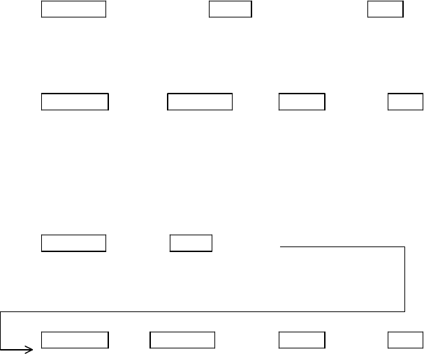
5.5.4.5.4 Changing the content of priority for NMEA input(NMEA PRESET)
(1) (1) When NMEA PRESET is selected from CUSTOM items and the "ENT" key is pressed, the NMEA
PRESET screen (See chart below) appears.
(2) (2) Select items with up-down cursor keys and contents of NMEA formatter with left-right cursor keys.
(3) (3) Change the priority of NMEA formatter with encoder knob.
(4) (4) The formatter in the left position has a higher priority than that of the right position.
Repeat this operation when multiple settings are necessary.
(5) After the setting is completed, exit from the NMEA PRESET screen with the "ENT" key. To suspend
the changes press the ENT key. All newly set items will be cancelled.
5.5.4.5.5 Changing the content of settings (ADJUST)
The items in the ADJUST menu are used for setting up the equipment at installation, retrofitting, etc.
where various functional parameters need to be set up or reset. Once set up, resetting may be not necessary.
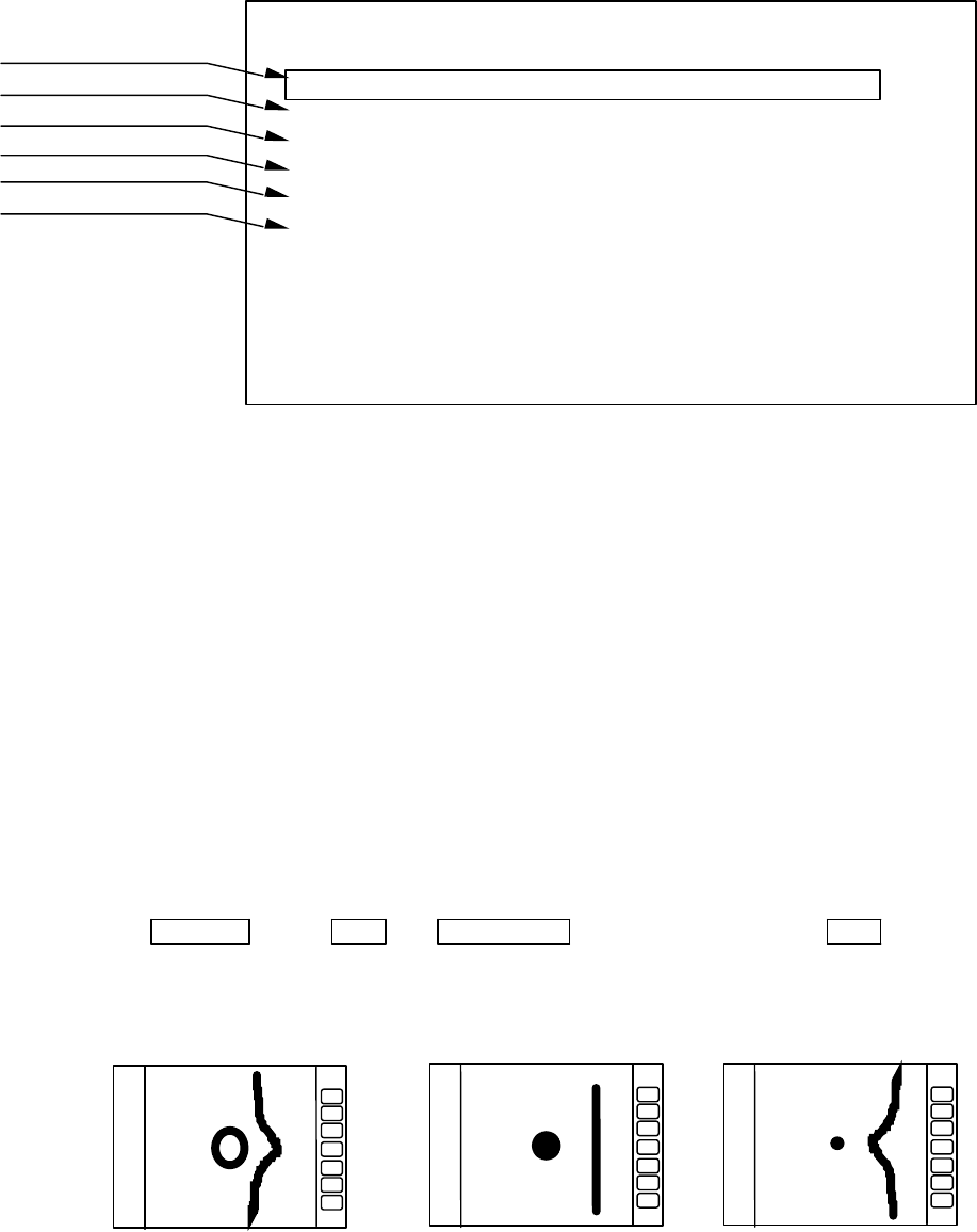
(1) Adjusting distance (TX TIME DELAY ADJ)
This adjustment is necessary to set up the distance to targets to within the specified accuracy. Before
proceeding to adjustment, set respective controls as follows:
(5) First, set the range scale to 0.25 NM, FTC to minimum, and GAIN to optimum level. Then adjust STC to
minimize the center spot ( a split of transmission energy shown like a sun) to a single dot.
(2) Adjusting the distance.
(2)-1 Select ADJUST by "common operations for CUSTOM". Use the up or down cursor key to select
TIMING ADJ from the pull-down menu and press the "ENT" key.
(2)-2 Find a straight linear target such as a jetty, bridge, etc.
(2)-3 Turn the rotary control either CW or CCW to obtain a linear echo shown like the one in Figure
b).
(2)-4 Press the "ENT" key to exit from this menu.
Up/Down → ENT → Control knob → ENT
To select TIMIG ADJ Do Timing adjustment Fix TX Timing
Delay
a) Pushing echo
(TX delay too much) b) Properly set c) Pulling echo
(TX delay too short)
a)Lat/Lon
b) Heading
c) Ship's speed
d) Way point
e)Depth of water
f) Cross track error
NMEA PRESET
L/L GGA>GLL>RMA>RMC
HEAD HDT>HDG>HDM>HSC>VHW>VTG
SPEED VHW>VTG>RMA>RMC
WAY POINT BEC>BWC>BWR>BER>BPI>RMB
DEPTH DBT>DPT
XTE RMB>XTE
SET WITH CONTROL KNOB
PRESS ENTER KEY TO RETURN
75
(2) Adjusting angle (HEAD ADJ)
The purpose of this adjustment is to exactly orient the Heading Mark on the screen with the ship’s bow
direction.
Note: Heading offset value for open antenna is different from that of a radome antenna.
(1) In preparation for adjusting the angle, the following adjustments are to be conducted.
(1)-1 Find one small target within a 0.5 to 1.5 NM range which, lying in the bow direction, can be visually
observed and is clearly recognized on the radar screen.
(1)-2 Measure the bearing of this target from the bow direction using a compass. Let it be θc.
(1)-3 Measure the bearing of the above target in head up (HU) mode using EBL. Let it be θr.
(1)-4 Calculate the following:
θc - θr : if θc is greater than θr
360 - ( θr - θc ) : if θr is greater than θc
The obtained value is the azimuth error of your radar at installation. If θc and θr are equal, the ad-
justment described below is unnecessary.
(2) Adjustment procedure
(2)-1 Select ADJUST by "common operations for CUSTOM" and select HEAD ADJ from among the
pull-down menu using the up or down cursor key. Press the "ENT" key to fix the HEAD ADJ
item.
(2)-2 Rotate the rotary control to set the value calculated.
(2)-3 When the adjustment is finished, press the "ENT" key to exit from this menu.
Up/Down → ENT → Control knob → ENT
Select HEAD ADJ. Set a value to .
(3) Adjusting receiver tuning (TUNING CAL)
Normally you do not need to make this adjustment. This adjustment may be necessary to ensure normal
automatic tuning operation. However, if the echo sensitivity is poor or there is any symptom suggesting
improper tuning, you may need to re-adjust the tuning by the following procedures.
(1) Choose several stable video images in the 3 NM range or more.
(2) Select ADJUST by "common operations for CUSTOM", and select TUNING CAL using the up or
down cursor key from the pull-down menu. Press the "ENT" key to fix the selection.
(3) The tuning adjustment screen (TUNING CALIBRATION) will appear, and then select AUTO with
up-down cursor key.
HEAD DIRECTION ADJUSTMENT
ADJUST WITH CONTROL KNOB
PRESS ENTER KEY TO RETURN
_358.8°_
HEADING Adjustment
3
1
HU
Adjust with Control knob
76
(4) Rotate the rotary control either CW or CCW to obtain the largest echo presentation on the screen.
(5) Select MANUAL with the down cursor key.
(6) Rotate the rotary control again to obtain the largest echo presentation.
(7) When the adjustment is finished, press the "ENT" key to exit from the TUNING CALIBRATION
screen.
Operate of (3) to (7)
Up/Down → Control knob → Up/Down → Control knob → ENT
Select AUTO Adjust tuning Select MANU Adjust tuning
(4) Adjusting the antenna height (ANTENNA)
Depending on the position at which the antenna is installed, the STC level may need to changed. Use the
following procedures to set up. To obtain the best result, we suggest consulting your local SIMRAD dealer
for proper setting.
(1) Select ADJUST by "common operations for CUSTOM", and then select ANTENNA from the pull-down
menu using up or down cursor key. Press the "ENT" key to fix the selection.
(2) The adjustment screen will be shown. Set an appropriate value using the rotary control to choose the
value from 1 to 9.
(3) Press the "ENT" key to exit from this menu.
Up/Down → ENT → Control knob → ENT
Select ANTENNA Choose value Complete
Adjust with control
knob
Select with up-down
cursor key
Echo remain.
TUNING CALIBRATION
READ OPERATION MANUAL
SELECT ITEM WITH ↑ ↓ KEY
TUNE WITH CONTROL KNOB
PRESS ENTER KEY TO MEMORY
AUTO 31
MANUAL 36
3
1
HU
Adjust with Control knob
STC CURVE ADJUSTMENT
ADJUST WITH CONTROL KNOB
PRESS ENTER KEY TO MEMORY
STC CURVE _5_
3
1
HU
ANTENNA Adjustment
77
(5) Setting the receiver GAIN (GAIN)
Using this function, you can set up the automatic and manual gain level. As widely accepted conven-
tion, the receiver gain should be set to the level that the noise speckles is slightly shown on the screen.
There are two modes of setting for AUTO and MANUAL, to each mode you can independently set the
GAIN level. Use the following procedure to set up.
In MANUAL mode, you can preset the MANUAL GAIN to current MANUAL gain level as standard.
When you enter "G60" as gain level, for instance, "G60" will be preset as standard MANUAL level.
(1) Select ADJUST by "common operations for CUSTOM" and select GAIN from the pull-down menu
items. Press the "ENT" key to fix the selection.
(6) Turn the rotary control to set the desired level from 1 to 30.
(7) Press the "ENT" key to fix the setting.
Up/Down → ENT → Control knob → ENT
Select GAIN Choose value Complete
(6) Setting the STC level (STC)
Using this function, you can set up the STC level to your needs. Proper STC setting should be such that
small targets such as buoy and small craft are clearly shown while slight sea clutter appears on the screen. In
AUTO mode, you can preset the AUTO STC level and AUTO FTC level as well. When entered at HARBOR
(HBR) mode, you can preset the HARBOR STC level.
In MANUAL mode, you can preset the best suited STC level as standard MANUAL STC level.
(1) Select ADJUST by "common operations for CUSTOM", and select STC from the pull-down menu. Press
the "ENT" key to fix the selection.
(2) The set up screen will be displayed. Rotate the rotary control to obtain an appropriate STC level on the
screen. The STC digital value will change from 1 to 16.
(3) Press the "ENT" key to exit from the adjustment screen.
Up/Down → ENT → Control knob → ENT
Select STC Choose value Complete
5.5.4.5.6 ATA preset (ATA PRESET)
Before using the ATA function, the settings described below are necessary.
Note: Use the ATA function in either the PPI or ALL PPI mode. Even if other modes are used, the ATA
still continues tracking though the symbols and data are not displayed on the radar.
Select the ATA PRESET items from the SET UP/CUSTOM menu. The menu contents are as follows.
(1) When ATA PRESET is selected from CUSTOM items and the "ENT" key is pressed, the ATA PRESET
screen (See chart below) appears.
(2) Select items with up-down cursor keys and change the value of each item with encoder knob.
(3) Change the item of VECT(vector) MODE with right-left cursor keys.
(4) Change the item of ATA with right-left cursor keys.
--------------------------------------------------------
CPA SET 0.0 NM
TCPA SET 0 MIN
VECT SET 6 MIN
VECT MODE REL TRUE
ATA ON OFF
--------------------------------------------------------
Check that ON in the ATA items is highlighted. If OFF is highlighted (selected), the ATA does not function.
* Unless the ATA board is installed properly, the ATA PRESET items are not displayed on the above SET
UP/CUSTOM menu.

78
5.6 ATA Operation
5.6.1 ATA Board Specifications
(1) Acquisition Manual
A target is acquired manually by a cross cursor driven
by the Pointing Device.
(2) Tracking Automatic
(3) Number of tracked targets 10 targets maximum
(4) ATA data output Target Number, distance, bearing, speed, course,
CPA and TCPA
(5) Alarm Collision alarm, activated when a target enters
the preset CPA and TCPA ranges.
Lost alarm, activated when a target can no longer
be tracked.
(6) Display Symbols: Predicted point and target number
Vector : Predicted motion of a target as a result of
own ship's direction and speed input.
Display modes: Relative (REL)/True (TRUE)
(7) Tracking range 0.5 to 40 NM
(8) PRF 2,000 Hz maximum
(9) Bearing signal 1,080 or 2,048 pulses / rev (Switched automatically)
See Note.
Note: The ATA board does not accept bearing signals other than specified above. In case the ATA board is
used in the monitor mode display, make sure an incoming bearing pulse rate agrees with that specified in this
specification.
5.6.2 Operating Instructions
5.6.2.1 Outline
The ATA detects a target from radar image signals and measures the distance from the target and its bearing
automatically. By calculating changes in the measurement results to predict the target movement, the ATA
tracks the target automatically.
The ATA calculates the CPA (closest point of approach) and the TCPA (time required for the ship to reach
the CPA) from the movement of the target toward the ship. Then comparing them to those preset, it generates
a collision alarm if both values are smaller than the preset ones.
The target bearings are calculated by (1) bearing of the target toward the ship and (2) bearing of the ship's
heading marker. Therefore, the accuracy of the data on the heading marker's bearing affects tracking per-
formance. Tracking may become impossible if the compass is inaccurate and especially when the ship is
yawing or changing the course. These cases, however, are not caused by a malfunction of ATA.
5.6.2.2 Setting
Before using the ATA function, the settings described below are necessary.
Note: Use the ATA function in either the PPI or ALL PPI mode. Even if other modes are used, the ATA
still continues tracking though the symbols and data are not displayed on the radar.
(1) Switching the ATA function ON/OFF
Select the ATA PRESET items from the SET UP/CUSTOM menu.
The menu contents are as follows.
-------------------------------------------------------
CPA SET 0.0 NM
TCPA SET 0 MIN
VECT SET 6 MIN
VECT MODE REL TRUE
ATA ON OFF
-------------------------------------------------------
Check that ON in the ATA items is highlighted. If OFF is highlighted (selected), the ATA does not function.
* Unless the ATA board is installed properly, the ATA PRESET items are not displayed on the above SET
UP/CUSTOM menu.

79
5.6.2.3 Operation
(1) Acquisition of a target
Firstly, select the target to track. Place the cursor on the target image and acquire it by using the ACQ (ac-
quisition) function.
Press the ACQ key. When operating from the MENU, place the cursor on NAVI/ACQ and press the ENT
key.
Select the target when it is displayed clearly and no other targets are displayed around it. If other targets are
displayed around it, the ATA may track a different one.
All targets acquired by ATA are identified by the numbers, from 0 to 9. These figures will be shown in the
upper right window on the screen. A vacant column shown like "-" indicates no target being acquired.
Before starting selection, use the TGT NUM (target number) function so that "-" is highlighted.
The TGT NUM function is used to change the target numbers. The target number will not change auto-
matically unless this function is used.
Press the TGT NUM key. When operating from the MENU, place the cursor on NAV/TGT NUM and press
the ENT key.
When ATA starts acquisition, a symbol appears at the cursor position on the screen, and the target number is
shown on the lower right side of the symbol.
(2) Tracking the target
When the operator acquired the target by the procedure (1), ATA automatically detects the target to start
automatic tracking. As soon as stable tracking is established, a vector will be developed on the screen.
The target tracking is not relevant to the range scale in use, i.e. the tracking continues even if the range scale
is changed beyond the viewable ranges for the target.
Note: A tracked small target may be lost when the range scale is changed to shorter pulse ranges, causing
the target signal level to be decreased. This may lead to a tracking failure on the target that will become a lost
target.
(3) Canceling target tracking
To cancel tracking, use the DEL (delete) function. The number highlighted on the upper right of the screen
will disappear. If ALL DEL (delete all) is selected, the ATA will cancel tracking of all targets.
Press the soft key if the DEL function has been set.
When operating from the MENU, place the cursor on NAVI/DEL or NAVI/ALL DEL and press the ENT
key. When the radar is set to the SY'BY mode, the ATA will cancel tracking of all targets.
(4) Data display
When necessary, numerical data of the current tracking target can be displayed in the data display window.
Use the DATA function to display the numerical data of the number highlighted on the upper right corner of
the screen. Press the soft key if the DATA function has been set.
When operating from the MENU, place the cursor on NAVI/DATA and press the ENT key.
Items to be displayed are as follows.
Target number: TGT NO.x The number of the target currently displayed.
Vector time: TIME xx MIN. Setting time to display vector length. (Speed x Time=vector length)
Vector mode: TRUE or REL Display mode of vector and data. TRUE and REL represent true and
relative speeds, respectively.
Target data: BRG (bearing), DIST (distance), CRS (course), SPD (speed),
CPA (closest point of approach) and
TCPA (time required for the ship to reach the CPA)
State: A collision or lost alarm will appear according to
the state of the target.
Example:
------------------------------------------------------------------------------------------------------------
| TGT No.x ALM LOST TIME xxMIN TRUE |
------------------------------------------------------------------------------------------------------------
| BRG 123.4DEG CRS 234.5DEG CPA 12.3NM |
| DIST 12.3NM SPD 10.0KT TCPA 12.3MIN |
-------------------------------------------------------------------------------------------------------------

80
(5) ATA indications
In the PPI and ALL PPI modes, symbols and data are displayed. In other modes, target tracking is still
continued though the ATA display and operation are disabled. The symbols are as follows:
Acquired
target Tracked target Target with data
display Lost target Dangerous target under
automatic tracking
(6) Ship's speed setting
The ship's speed can be set in the SPD SET item in the SET UP/CUSTOM/PRESET2 menu. Other than the
standard NMEA interface, manual setting and log pulse input can also be selected. In the case of manual
setting, input the ship's actual speed. Menu indication is as follows:
----------------------------------------------------------------------------------------
SPD SET NMEA MANU 0.0 KT LOG 200P
----------------------------------------------------------------------------------------
5.6.2.4 Interface
(1) Data output
The ATA data output is ready at the optional connector terminal on the rear of the display unit. Pin No.32 is
the NMEA_OUT signal terminal which outputs signals conforming to the NMEA0183. This output terminal
is used for the TARGET function (to output L/L of the cursor position), the MOB function (to output L/L of
the ship's position) and the ATA data output function.
The data format is as follows:
$RATTM,01,0.42,292.1,T,4.99,0.0,T,0.4,0.0,N,,T,,,M*2A
Description
$RA Unit identification code (radar)
TTM Formatter
01 Target number
0.42 Distance to the target
292.1 Bearing of the target (°)
T Indicates the true bearing.
4.99 Speed (knots)
0.0 Course (°)
T Indicates the true speed and course, while R indicates relative movement.
0.4 Indicates the CPA (closest point of approach)
0.0 Time required for the ship to reach the CPA (min.)
N Indicates the unit of distance used: NM
T Indicates tracking condition: Q: unstable, T: tracking, L: lost
M Indicates that acquisition is carried out manually.
*2A Sum checking
(2) Log signal input
The log signal can be used for ship speed input by inputting it to the optional connector terminal on the rear of
the display unit. Pin No.32 is the log signal terminal and it is driven between itself and pin No.14 (GND)
using contact signals such as a relay.
400, 200, 150 or 100 pulses/NM signal can be selected.